

Page 1
Electric Chain Hoist
Series CPE
Mod. CPE/F
Capacity 1600 kg - 5000 kg
Yale
electric
Operating and Maintenance Manual
Spare Parts Catalog
Yale Industrial Products GmbH
P. O. Box 10 13 24 • D-42513 Velbert, Germany
Am Lindenkamp 31 • D-42549 Velbert, Germany
Tel. 2051-600-0 • Fax 2051-600-127
Ident.-No. 09900069 / 10.02
Page 2
Yale
electric
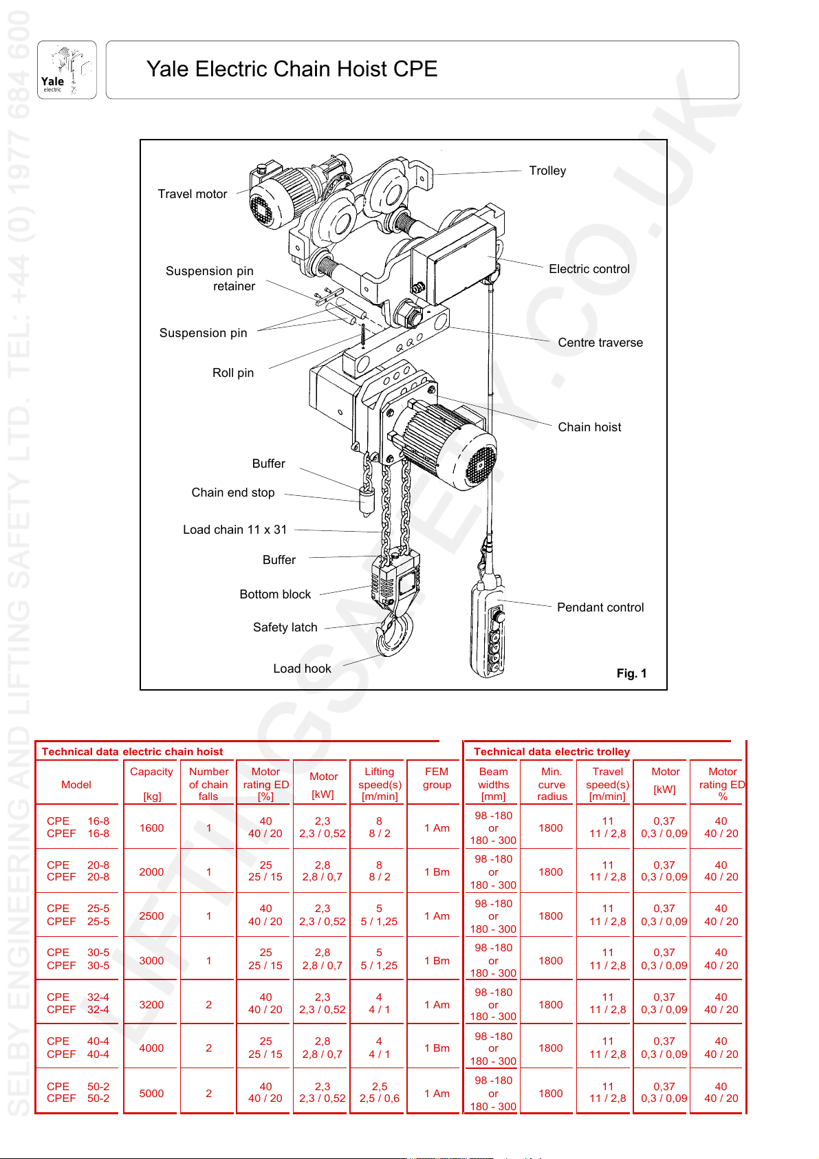
Yale Electric Chain Hoist CPE
Trolley
Travel motor
Suspension pin
retainer
Suspension pin
Roll pin
Chain end stop
Load chain 11 x 31
Electric control
Centre traverse
Chain hoist
Buffer
Buffer
Bottom block
Pendant control
Safety latch
Load hook
Technical data electric chain hoist Technical data electric trolley
Model
CPE 16-8
CPEF 16-8
CPE 20-8
CPEF 20-8
CPE 25-5
CPEF 25-5
CPE 30-5
CPEF 30-5
CPE 32-4
CPEF 32-4
CPE 40-4
CPEF 40-4
CPE 50-2
CPEF 50-2
Capacity
[kg]
1600 1
2000 1
2500 1
3000 1
3200 2
4000 2
5000 2
Number
of chain
falls
Motor
rating ED
[%]
40
40 / 20
25
25 / 15
40
40 / 20
25
25 / 15
40
40 / 20
25
25 / 15
40
40 / 20
Motor
[kW]
2,3
2,3 / 0,5288 / 2
2,8
2,8 / 0,7
2,3
2,3 / 0,5255 / 1,25
2,8
2,8 / 0,755 / 1,25
2,3
2,3 / 0,5244 / 1
2,8
2,8 / 0,7
2,3
2,3 / 0,52
Lifting
speed(s)
[m/min]
8
8 / 2
4
4 / 1
2,5
2,5 / 0,6
FEM
group
1 Am
1 Bm
1 Am
1 Bm
1 Am
1 Bm
1 Am
Beam
widths
[mm]
98 -180
or
180 - 300
98 -180
or
180 - 300
98 -180
or
180 - 300
98 -180
or
180 - 300
98 -180
or
180 - 300
98 -180
or
180 - 300
98 -180
or
180 - 300
Min.
curve
radius
1800
1800
1800
1800
1800
1800
1800
Travel
speed(s)
[m/min]
11
11 / 2,8
11
11 / 2,8
11
11 / 2,8
11
11 / 2,8
11
11 / 2,8
11
11 / 2,8
11
11 / 2,8
Fig. 1
Motor
[kW]
0,37
0,3 / 0,094040 / 20
0,37
0,3 / 0,094040 / 20
0,37
0,3 / 0,094040 / 20
0,37
0,3 / 0,094040 / 20
0,37
0,3 / 0,094040 / 20
0,37
0,3 / 0,094040 / 20
0,37
0,3 / 0,094040 / 20
Motor
rating ED
%
2
Page 3
Yale Electric Chain Hoist CPE
Yale
electric
TABLE OF CONTENTS PAGE
1. GENERAL INFORMATION 3
2. OPERATING INSTRUCTIONS 3
2.1 Correct operation 3
Maximum capacity 3
Danger zones 3
Attaching the hoist / trolley 3
Temperature range 4
Regulations 4
Maintenance / repair 4
2.2 Incorrect operation 4
2.3 Initial operation 4
Inspection before initial operation 4
Inspection before starting work 4
Inspection of load chain 4
Inspection of chain end stop 4
Inspection of chain reeving 4
Inspection of suspension and load hooks 5
Attaching the load 5
Inspect the traverse (for trolleys) 5
Check adjustment of trolley width 5
3. ASSEMBLY 5
3.1 Inspection before assembly 5
3.2 Electric chain hoist with hook suspension
(Standard version) 5
3.3 Electric chain hoist with trolley 5
Assembly of the trolley 6
2.4 Electrical connection 6
Preparation 6
Mains supply connection 6
1. GENERAL INFORMATION
Attention: All users must read these operating instructions
carefully prior to the initial operation. These instructions
are intended to acquaint the user with the hoist / trolley and
enable hime to use it to the full extent of its intended
capabilities.
The operating instructions contain important information
on how to handle the hoist / trolley in a safe, correct and
economic way. Acting in accordance with these instructions
helps to avoid dangers, reduce repair costs and downtime
and to increase the reliability and lifetime of the hoist / trolley.
Anyone involved in doing any of the following work with the
hoist / trolley must read the operating instructions and act
accordingly:
• operation, including preparation, trouble shooting and
cleaning
• maintenance, inspection, repair
• transport
Apart from the operating instructions and the accident
prevention act valid for the respective country and area where
the hoist / trolley is used, also the commonly accepted
regulations for safe and professional work must be adhered
to.
Every unit leaving the factory is furnished with a test certificate
that shows the serial number of the hoist / trolley . This
certificate has to be filed together with the inspection
manual (see page 30).
The continuous sound level at the place of work is equal to
73 dB. The measurements were taken at a distance of 1 m
from the hoist at 9 positions in accordance with DIN 45635,
precision class 2.
4. FUNTIONAL TEST AFTER ASSEMBLY 6
5. OPERATION 7
Installation, service, operation 7
Traversing the trolley 7
Attaching the load 7
Lifting / lowering the load 7
Emergency stop 7
6. SERVICE 8
6.1 Daily checks 8
6.2 Regular inspections, service and testing 8
6.3 Load chain 9
Lubricating the load chain 9
Inspecting the load chain for wear 9
Replace the load chain 9
1-strand design 9
2-strand design 9
6.4 Load and suspension hooks 10
6.5 Trolleys 10
6.6 Electric chain hoist in general 10
6.7 Overload protection device 10
6.8 Gearbox 10
Check oil level 10
Oil change 10
Disassembly and reassambly 11
6.9 Maintenance of the motor 11
Motor 11
Disc brake 11
2. OPERATING INSTRUCTIONS
2.1 Correct operation
Maximum capacity
• The Yale electric chain hoist model CPE is designed to lift
and lower loads up to the rated capacity. The lifting capacity
indicated on the hoist / trolley is the maximum safe working
load which must not be exceeded.
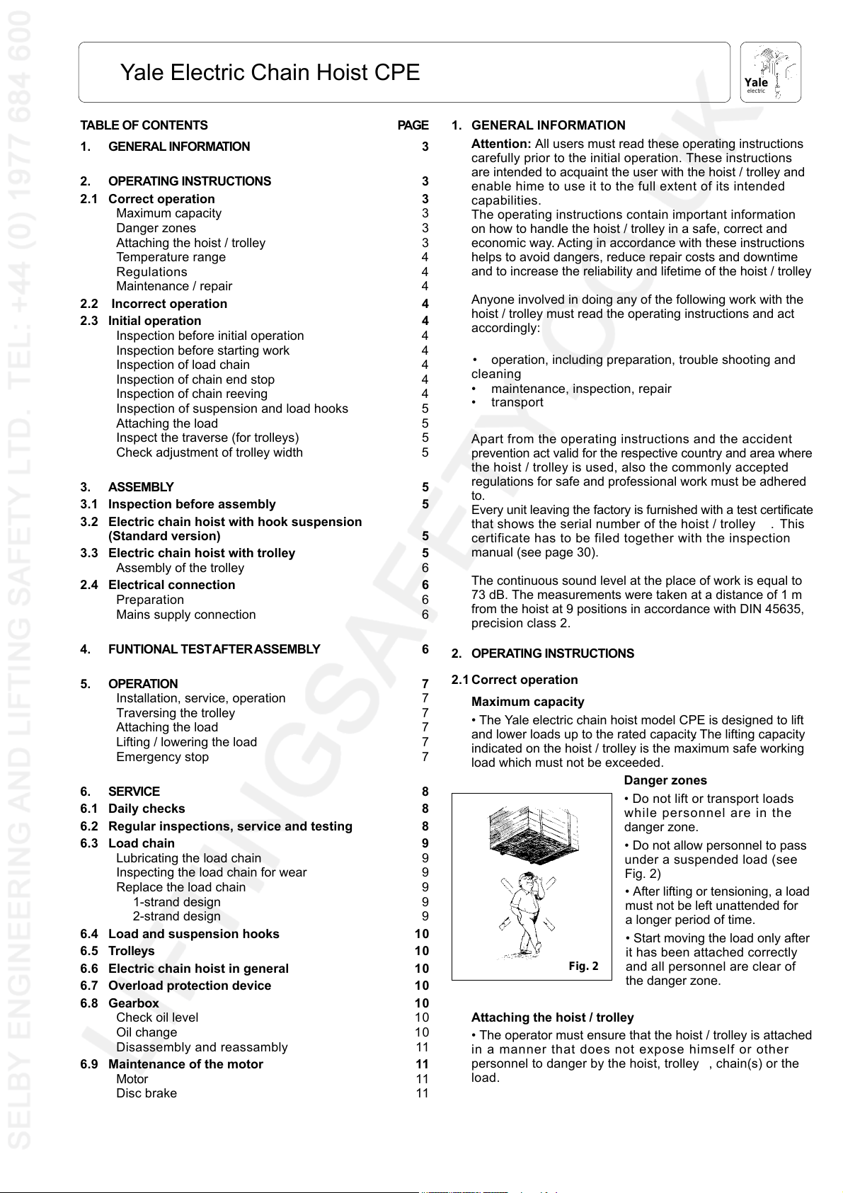
Danger zones
• Do not lift or transport loads
while personnel are in the
danger zone.
• Do not allow personnel to pass
under a suspended load (see
Fig. 2)
• After lifting or tensioning, a load
must not be left unattended for
a longer period of time.
• Start moving the load only after
Fig. 2
Attaching the hoist / trolley
• The operator must ensure that the hoist / trolley is attached
in a manner that does not expose himself or other
personnel to danger by the hoist, trolley , chain(s) or the
load.
it has been attached correctly
and all personnel are clear of
the danger zone.
3
Page 4
Yale
electric
Yale Electric Chain Hoist CPE
Temperature range
• The hoist / trolley can be operated in ambient temperatures
between -10
O
C und +50O C. Consult the manufacturer in
case of extreme working conditions.
Note: At ambient temperatures below 0
O
C check the brake
is not frozen.
Regulations
• The accident prevention act and/or safety regulations of
the respective country for using manual and electric hoists
must be strictly adhered to. In Germany these are VBG 8,
VBG 9, VBG 9a, ZH 1/25, ZH 1/27, and VDE 0100 resp.
VDE 0130.
Maintenance / Repair
• In order to ensure correct operation, not only the operating
instructions, but also the conditions for inspection and
maintenance must be complied with. If defects are found
stop using the hoist / trolley immediately.
Attention: Before starting work on electrical components
switch OFF the main current switch and secure it against
unintentionally being switched back on.
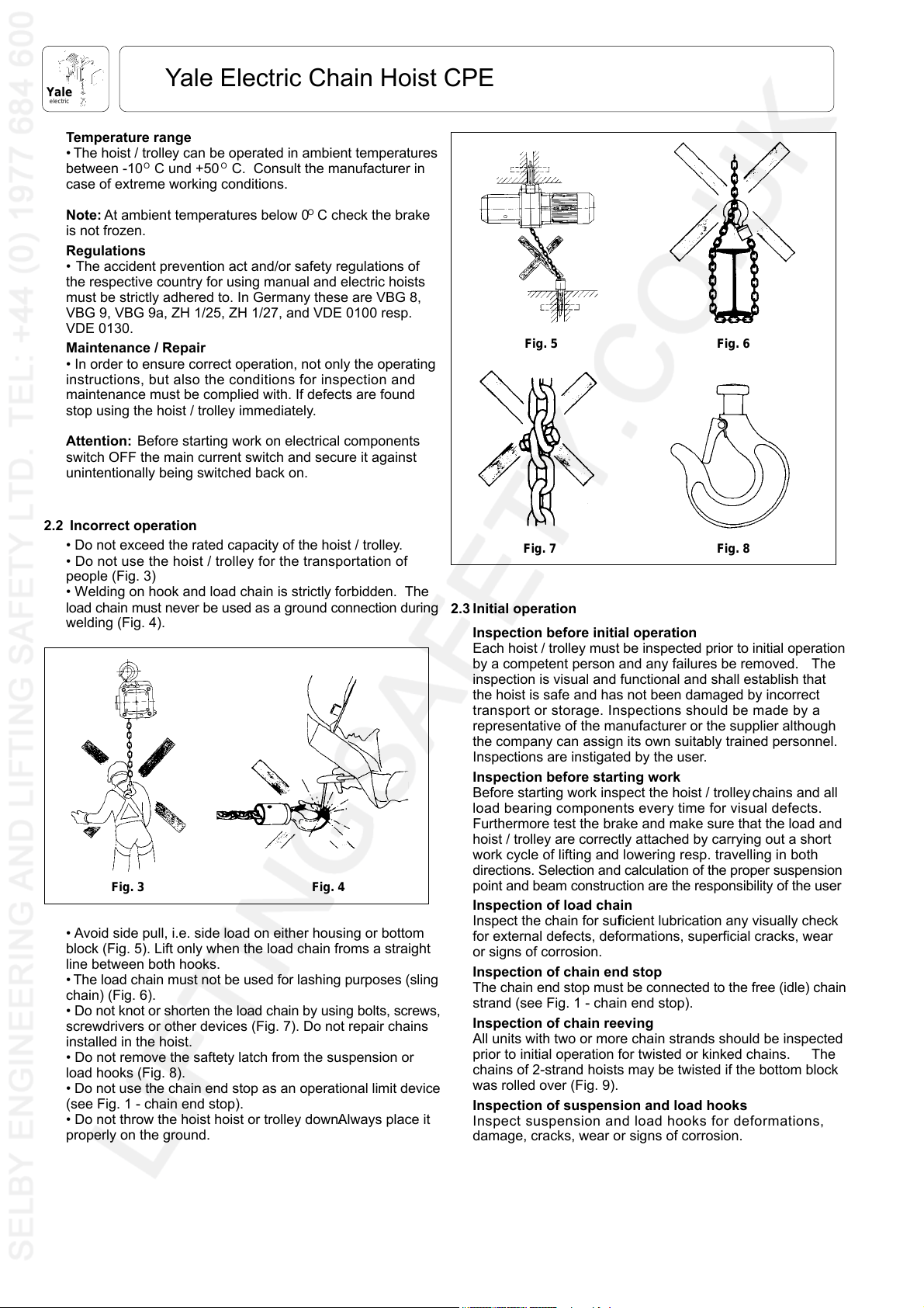
2.2 Incorrect operation
• Do not exceed the rated capacity of the hoist / trolley.
• Do not use the hoist / trolley for the transportation of
people (Fig. 3)
• Welding on hook and load chain is strictly forbidden. The
load chain must never be used as a ground connection during
welding (Fig. 4).
Fig. 3
Fig. 4
• Avoid side pull, i.e. side load on either housing or bottom
block (Fig. 5). Lift only when the load chain froms a straight
line between both hooks.
• The load chain must not be used for lashing purposes (sling
chain) (Fig. 6).
• Do not knot or shorten the load chain by using bolts, screws,
screwdrivers or other devices (Fig. 7). Do not repair chains
installed in the hoist.
• Do not remove the saftety latch from the suspension or
load hooks (Fig. 8).
• Do not use the chain end stop as an operational limit device
(see Fig. 1 - chain end stop).
• Do not throw the hoist hoist or trolley down. Always place it
properly on the ground.
Fig. 5
Fig. 6
Fig. 8Fig. 7
2.3 Initial operation
Inspection before initial operation
Each hoist / trolley must be inspected prior to initial operation
by a competent person and any failures be removed. The
inspection is visual and functional and shall establish that
the hoist is safe and has not been damaged by incorrect
transport or storage. Inspections should be made by a
representative of the manufacturer or the supplier although
the company can assign its own suitably trained personnel.
Inspections are instigated by the user.
Inspection before starting work
Before starting work inspect the hoist / trolley, chains and all
load bearing components every time for visual defects.
Furthermore test the brake and make sure that the load and
hoist / trolley are correctly attached by carrying out a short
work cycle of lifting and lowering resp. travelling in both
directions. Selection and calculation of the proper suspension
point and beam construction are the responsibility of the user.
Inspection of load chain
Inspect the chain for sufficient lubrication any visually check
for external defects, deformations, superficial cracks, wear
or signs of corrosion.
Inspection of chain end stop
The chain end stop must be connected to the free (idle) chain
strand (see Fig. 1 - chain end stop).
Inspection of chain reeving
All units with two or more chain strands should be inspected
prior to initial operation for twisted or kinked chains. The
chains of 2-strand hoists may be twisted if the bottom block
was rolled over (Fig. 9).
Inspection of suspension and load hooks
Inspect suspension and load hooks for deformations,
damage, cracks, wear or signs of corrosion.
4
Page 5
Yale Electric Chain Hoist CPE
Yale
electric
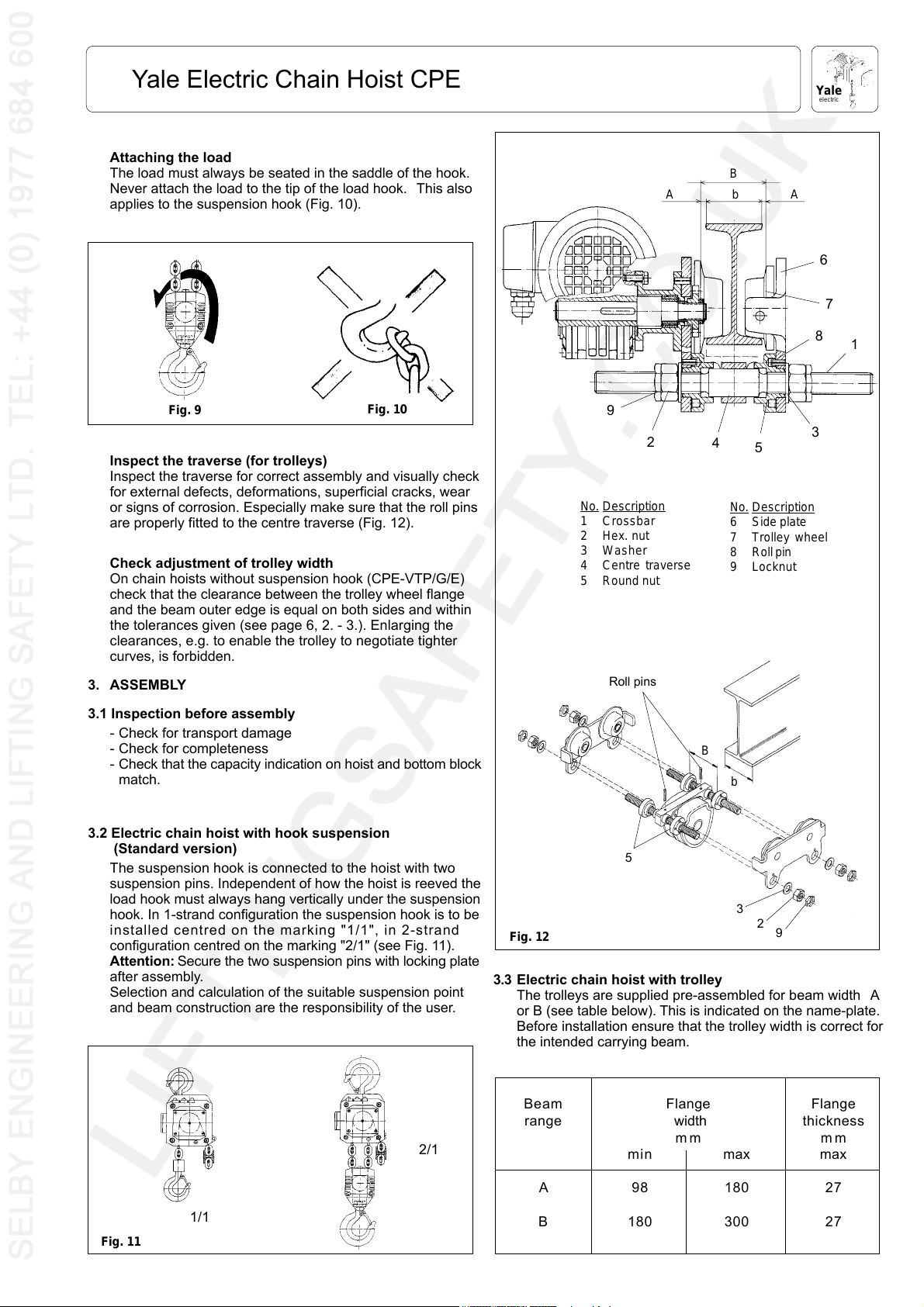
Attaching the load
The load must always be seated in the saddle of the hook.
Never attach the load to the tip of the load hook. This also
applies to the suspension hook (Fig. 10).
Fig. 9
Fig. 10
Inspect the traverse (for trolleys)
Inspect the traverse for correct assembly and visually check
for external defects, deformations, superficial cracks, wear
or signs of corrosion. Especially make sure that the roll pins
are properly fitted to the centre traverse (Fig. 12).
Check adjustment of trolley width
On chain hoists without suspension hook (CPE-VTP/G/E)
check that the clearance between the trolley wheel flange
and the beam outer edge is equal on both sides and within
the tolerances given (see page 6, 2. - 3.). Enlarging the
clearances, e.g. to enable the trolley to negotiate tighter
curves, is forbidden.
3. ASSEMBLY
A
9
2
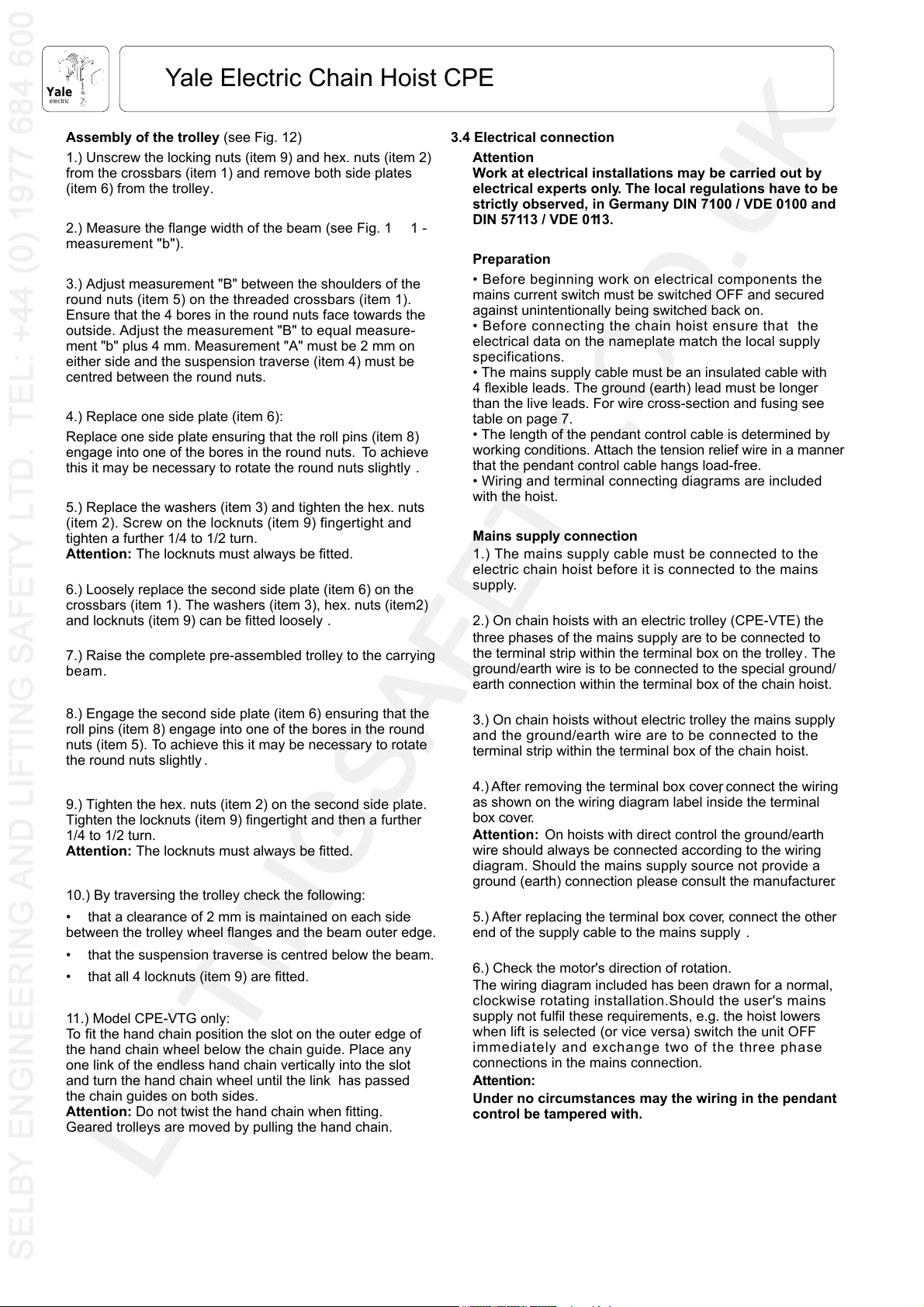
No. Description
1Crossbar
2 Hex. nut
3 Washer
4Centre traverse
5 Round nut
Roll pins
B
bA
4
5
No. Description
6Side plate
7Trolley wheel
8Roll pin
9 Locknut
6
7
8
1
3
3.1 Inspection before assembly
- Check for transport damage
- Check for completeness
- Check that the capacity indication on hoist and bottom block
match.
3.2 Electric chain hoist with hook suspension
(Standard version)
The suspension hook is connected to the hoist with two
suspension pins. Independent of how the hoist is reeved the
load hook must always hang vertically under the suspension
hook. In 1-strand configuration the suspension hook is to be
installed centred on the marking "1/1", in 2-strand
configuration centred on the marking "2/1" (see Fig. 11).
Attention: Secure the two suspension pins with locking plate
after assembly.
Selection and calculation of the suitable suspension point
and beam construction are the responsibility of the user.
2/1
B
b
5
3
2
Fig. 12
3.3
Electric chain hoist with trolley
9
The trolleys are supplied pre-assembled for beam width A
or B (see table below). This is indicated on the name-plate.
Before installation ensure that the trolley width is correct for
the intended carrying beam.
Beam Flange Flange
range width thickness
mm mm
min max max
Fig. 11
1/1
A98180 27
B 180 300 27
5
Page 6
Yale
electric
Yale Electric Chain Hoist CPE
Assembly of the trolley (see Fig. 12)
1.) Unscrew the locking nuts (item 9) and hex. nuts (item 2)
from the crossbars (item 1) and remove both side plates
(item 6) from the trolley.
2.) Measure the flange width of the beam (see Fig. 1 1 -
measurement "b").
3.) Adjust measurement "B" between the shoulders of the
round nuts (item 5) on the threaded crossbars (item 1).
Ensure that the 4 bores in the round nuts face towards the
outside. Adjust the measurement "B" to equal measure-
ment "b" plus 4 mm. Measurement "A" must be 2 mm on
either side and the suspension traverse (item 4) must be
centred between the round nuts.
4.) Replace one side plate (item 6):
Replace one side plate ensuring that the roll pins (item 8)
engage into one of the bores in the round nuts. To achieve
this it may be necessary to rotate the round nuts slightly .
5.) Replace the washers (item 3) and tighten the hex. nuts
(item 2). Screw on the locknuts (item 9) fingertight and
tighten a further 1/4 to 1/2 turn.
Attention: The locknuts must always be fitted.
6.) Loosely replace the second side plate (item 6) on the
crossbars (item 1). The washers (item 3), hex. nuts (item2)
and locknuts (item 9) can be fitted loosely .
7.) Raise the complete pre-assembled trolley to the carrying
beam.
3.4 Electrical connection
Attention
Work at electrical installations may be carried out by
electrical experts only. The local regulations have to be
strictly observed, in Germany DIN 7100 / VDE 0100 and
DIN 57113 / VDE 0113.
Preparation
• Before beginning work on electrical components the
mains current switch must be switched OFF and secured
against unintentionally being switched back on.
• Before connecting the chain hoist ensure that the
electrical data on the nameplate match the local supply
specifications.
• The mains supply cable must be an insulated cable with
4 flexible leads. The ground (earth) lead must be longer
than the live leads. For wire cross-section and fusing see
table on page 7.
• The length of the pendant control cable is determined by
working conditions. Attach the tension relief wire in a manner
that the pendant control cable hangs load-free.
• Wiring and terminal connecting diagrams are included
with the hoist.
Mains supply connection
1.) The mains supply cable must be connected to the
electric chain hoist before it is connected to the mains
supply.
2.) On chain hoists with an electric trolley (CPE-VTE) the
three phases of the mains supply are to be connected to
the terminal strip within the terminal box on the trolley. The
ground/earth wire is to be connected to the special ground/
earth connection within the terminal box of the chain hoist.
8.) Engage the second side plate (item 6) ensuring that the
roll pins (item 8) engage into one of the bores in the round
nuts (item 5). To achieve this it may be necessary to rotate
the round nuts slightly .
9.) Tighten the hex. nuts (item 2) on the second side plate.
Tighten the locknuts (item 9) fingertight and then a further
1/4 to 1/2 turn.
Attention: The locknuts must always be fitted.
10.) By traversing the trolley check the following:
• that a clearance of 2 mm is maintained on each side
between the trolley wheel flanges and the beam outer edge.
• that the suspension traverse is centred below the beam.
• that all 4 locknuts (item 9) are fitted.
11.) Model CPE-VTG only:
To fit the hand chain position the slot on the outer edge of
the hand chain wheel below the chain guide. Place any
one link of the endless hand chain vertically into the slot
and turn the hand chain wheel until the link has passed
the chain guides on both sides.
Attention: Do not twist the hand chain when fitting.
Geared trolleys are moved by pulling the hand chain.
3.) On chain hoists without electric trolley the mains supply
and the ground/earth wire are to be connected to the
terminal strip within the terminal box of the chain hoist.
4.) After removing the terminal box cover, connect the wiring
as shown on the wiring diagram label inside the terminal
box cover.
Attention: On hoists with direct control the ground/earth
wire should always be connected according to the wiring
diagram. Should the mains supply source not provide a
ground (earth) connection please consult the manufacturer.
5.) After replacing the terminal box cover, connect the other
end of the supply cable to the mains supply .
6.) Check the motor's direction of rotation.
The wiring diagram included has been drawn for a normal,
clockwise rotating installation.Should the user's mains
supply not fulfil these requirements, e.g. the hoist lowers
when lift is selected (or vice versa) switch the unit OFF
immediately and exchange two of the three phase
connections in the mains connection.
Attention:
Under no circumstances may the wiring in the pendant
control be tampered with.
6
Page 7
Yale Electric Chain Hoist CPE
Yale
electric
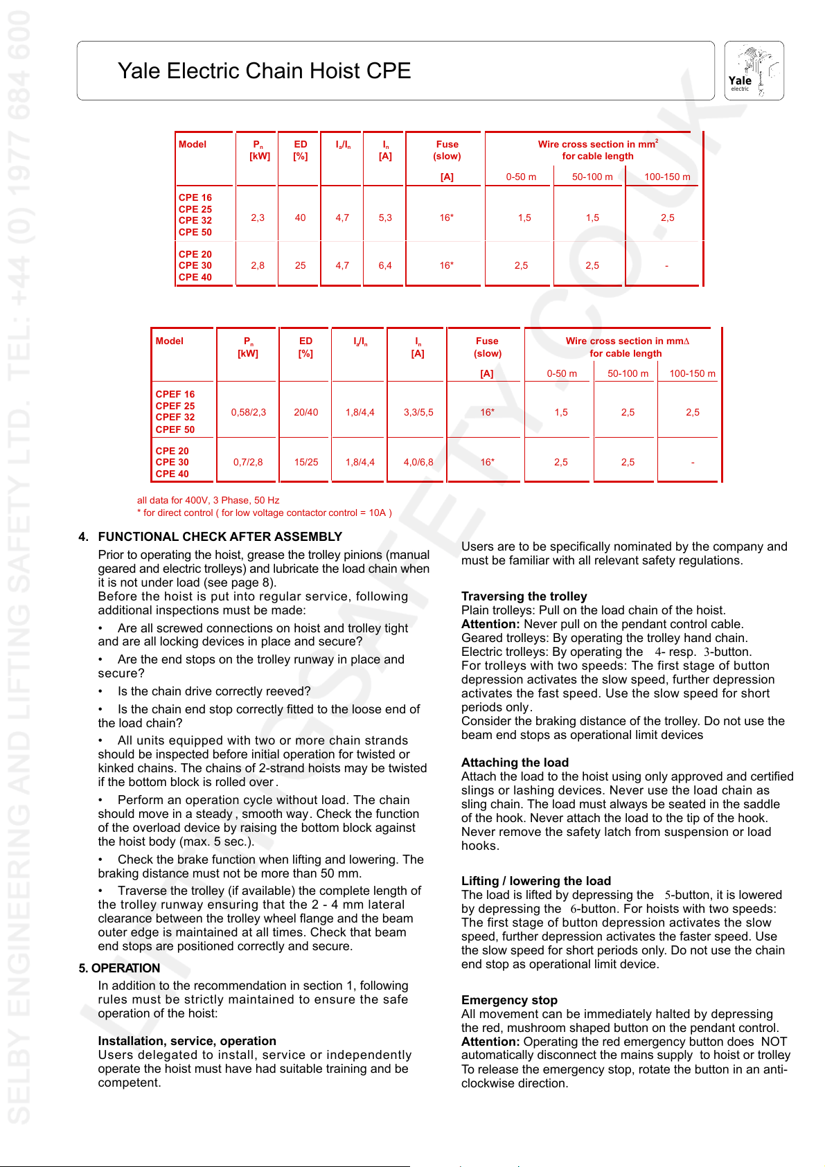
Model P
CPE 16
CPE 25
CPE 32
CPE 50
CPE 20
CPE 30
CPE 40
Model P
CPEF 16
CPEF 25
CPEF 32
CPEF 50
CPE 20
CPE 30
CPE 40
all data for 400V, 3 Phase, 50 Hz
* for direct control ( for low voltage contactor control = 10A )
n
[kW]ED[%]
2,3 40 4,7 5,3 16* 1,5 1,5 2,5
2,8 25 4,7 6,4 16* 2,5 2,5 -
n
[kW]
0,58/2,3 20/40 1,8/4,4 3,3/5,5 16* 1,5 2,5 2,5
0,7/2,8 15/25 1,8/4,4 4,0/6,8 16* 2,5 2,5 -
ED
[%]
I
a/In
[A]
I
a/In
4. FUNCTIONAL CHECK AFTER ASSEMBLY
Prior to operating the hoist, grease the trolley pinions (manual
geared and electric trolleys) and lubricate the load chain when
it is not under load (see page 8).
Before the hoist is put into regular service, following
additional inspections must be made:
• Are all screwed connections on hoist and trolley tight
and are all locking devices in place and secure?
• Are the end stops on the trolley runway in place and
secure?
• Is the chain drive correctly reeved?
• Is the chain end stop correctly fitted to the loose end of
the load chain?
• All units equipped with two or more chain strands
should be inspected before initial operation for twisted or
kinked chains. The chains of 2-strand hoists may be twisted
if the bottom block is rolled over.
• Perform an operation cycle without load. The chain
should move in a steady , smooth way. Check the function
of the overload device by raising the bottom block against
the hoist body (max. 5 sec.).
• Check the brake function when lifting and lowering. The
braking distance must not be more than 50 mm.
• Traverse the trolley (if available) the complete length of
the trolley runway ensuring that the 2 - 4 mm lateral
clearance between the trolley wheel flange and the beam
outer edge is maintained at all times. Check that beam
end stops are positioned correctly and secure.
5. OPERATION
In addition to the recommendation in section 1, following
rules must be strictly maintained to ensure the safe
operation of the hoist:
Installation, service, operation
Users delegated to install, service or independently
operate the hoist must have had suitable training and be
competent.
I
n
Fuse
(slow)
[A] 0-50 m 50-100 m 100-150 m
[A]
I
n
Fuse
(slow)
[A] 0-50 m 50-100 m 100-150 m
Wire cross section in mm
for cable length
Wire cross section in mm∆
for cable length
2
Users are to be specifically nominated by the company and
must be familiar with all relevant safety regulations.
Traversing the trolley
Plain trolleys: Pull on the load chain of the hoist.
Attention: Never pull on the pendant control cable.
Geared trolleys: By operating the trolley hand chain.
Electric trolleys: By operating the 4- resp. 3-button.
For trolleys with two speeds: The first stage of button
depression activates the slow speed, further depression
activates the fast speed. Use the slow speed for short
periods only.
Consider the braking distance of the trolley. Do not use the
beam end stops as operational limit devices
Attaching the load
Attach the load to the hoist using only approved and certified
slings or lashing devices. Never use the load chain as
sling chain. The load must always be seated in the saddle
of the hook. Never attach the load to the tip of the hook.
Never remove the safety latch from suspension or load
hooks.
Lifting / lowering the load
The load is lifted by depressing the 5-button, it is lowered
by depressing the 6-button. For hoists with two speeds:
The first stage of button depression activates the slow
speed, further depression activates the faster speed. Use
the slow speed for short periods only. Do not use the chain
end stop as operational limit device.
Emergency stop
All movement can be immediately halted by depressing
the red, mushroom shaped button on the pendant control.
Attention: Operating the red emergency button does NOT
automatically disconnect the mains supply to hoist or trolley.
To release the emergency stop, rotate the button in an anti-
clockwise direction.
7
Page 8
Yale
electric
Yale Electric Chain Hoist CPE
6. SERVICE
• Service and inspections may only be carried out by a
competent person.
• The inspection must determine that all safety devices
are present and fully operational and covers the condition
of the hoist, lifting gear , accessories and supporting con-
structions.
• The service intervals and inspections noted are for
normal working conditions. Adverse working conditions,
e.g. heat or chemical environments, can dictate shorter
periods.
•The Yale electric chain hoists conform to FEM group 1Am
resp. 1Bm in accordance with FEM 9.511. This results in a
theoretical service lifetime of 800 resp. 400 operating
hours under full load. This is equivalent to 10 years under
normal operating conditions. After this period the hoist
requires a general overhaul. Further information is con-
tained in VBG 9 resp. FEM 9.755.
6.1 Daily checks
1.) Visually check the pendant control switch and cable for
damage.
2.) Check that the brake funtions correctly.
3.) Check that the overload safety device functions correctly.
4.) Electric chain hoists with trolley:
- Check that the trolley runway is free from obstructions
- Check that the end stops on the trolley runway are
fitted and secure.
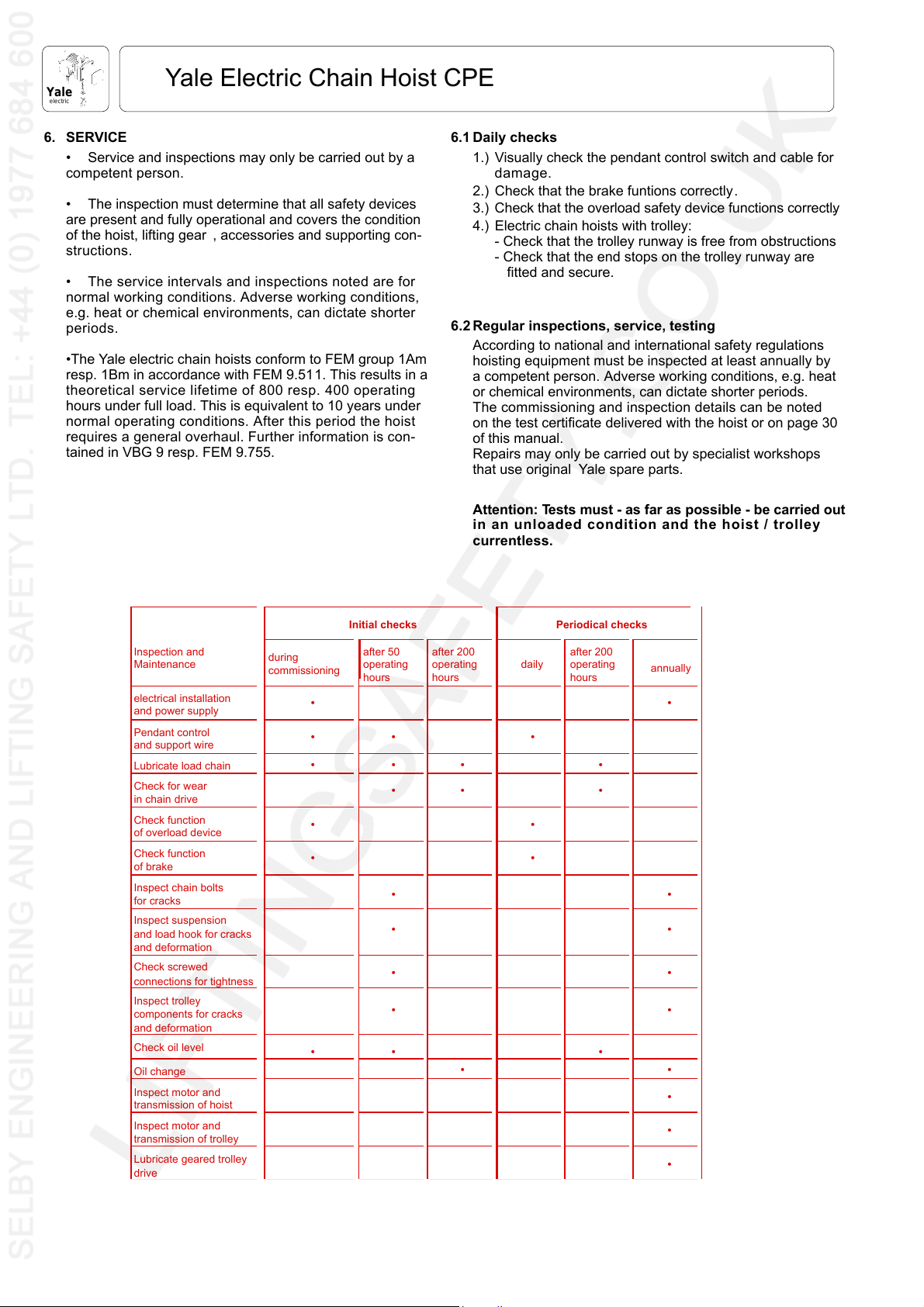
6.2 Regular inspections, service, testing
According to national and international safety regulations
hoisting equipment must be inspected at least annually by
a competent person. Adverse working conditions, e.g. heat
or chemical environments, can dictate shorter periods.
The commissioning and inspection details can be noted
on the test certificate delivered with the hoist or on page 30
of this manual.
Repairs may only be carried out by specialist workshops
that use original Yale spare parts.
Attention: Tests must - as far as possible - be carried out
in an unloaded condition and the hoist / trolley
currentless.
Inspection and
Maintenance
electrical installation
and power supply
Pendant control
and support wire
Lubricate load chain
Check for wear
in chain drive
Check function
of overload device
Check function
of brake
Inspect chain bolts
for cracks
Inspect suspension
and load hook for cracks
and deformation
Check screwed
connections for tightness
Inspect trolley
components for cracks
and deformation
Check oil level
Oil change
Inspect motor and
transmission of hoist
Inspect motor and
transmission of trolley
Lubricate geared trolley
drive
Initial checks Periodical checks
during
commissioning
• •
•• •
••• •
••
••
•• •
after 50
operating
hours
after 200
operating
hours
•• •
••
••
••
••
••
daily
after 200
operating
hours
annually
•
•
•
8
Page 9
Yale Electric Chain Hoist CPE
Yale
electric
6.3 LOAD CHAIN
The Yale load chain is grade 80 chain with the dimensions
11 x 31 mm. The CPE electric hoists are specially designed
to use this type of chain. For this reason only chains that
have been approved by the manufacturer may be used in
these hoists.
Lubricating the load chain
The load chain is to be lubricated before initial operation
and every 3 months but the latest after 200 operating hours.
Adverse working conditions, e.g. excessive dust or con-
tinued heavy duty can dictate shorter periods between
lubrication.
• Before the chain is lubricated it must be cleaned. Flame
cleaning is forbidden. Use only cleansing methods and
agents that do not corrode the chain material. Avoid
cleansing methods that can lead to hydrogen brittleness,
e.g. spraying or dipping chain in caustic solvents. Also avoid
surface treatments that can hide cracks and flaws or other
surface damage.
• The chain must be lubricated in a no-load condition so
that lubricant can enter between the links, e.g. by dipping in
oil.
• Motor oil of the voscosity 100, e.g. Shell Tonna T68 can
be used to lubricate the chain. For very dusty applications
use a dry lubricant.
Inspecting the load chain for wear
Load chains must be inspected every 3 months or the latest
after 200 operating hours (see VBG 8 § 27 or local regu-
lations).
Visually inspect the chain over its full length for defor-
mation, cracks, flaws, elongation, wear or corrosive pitting.
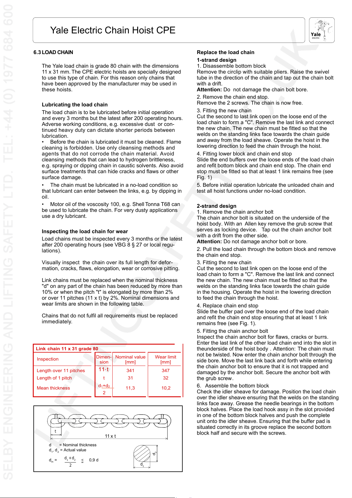
Link chains must be replaced when the nominal thickness
"d" on any part of the chain has been reduced by more than
10% or when the pitch "t" is elongated by more than 2%
or over 11 pitches (11 x t) by 2%. Nominal dimensions and
wear limits are shown in the following table.
Chains that do not fulfil all requirements must be replaced
immediately.
Link chain 11 x 31 grade 80
Inspection
Length over 11 pitches
Length of 1 pitch t 31 32
Mean thickness
t
d = Nominal thickness
d1, d2 = Actual value
d1 + d
dm = 0,9 d
2
2
Dimen-
<
=
sion
11⋅t
d
1+d2
2
11 x t
Nominal value
[mm]
341 347
11,3 10,2
d
1
Wear limit
[mm]
2
d
Replace the load chain
1-strand design
1. Disassemble bottom block
Remove the circlip with suitable pliers. Raise the swivel
tube in the direction of the chain and tap out the chain bolt
with a drift.
Attention: Do not damage the chain bolt bore.
2. Remove the chain end stop.
Remove the 2 screws. The chain is now free.
3. Fitting the new chain
Cut the second to last link open on the loose end of the
load chain to form a "C". Remove the last link and connect
the new chain. The new chain must be fitted so that the
welds on the standing links face towards the chain guide
and away from the load sheave. Operate the hoist in the
lowering direction to feed the chain through the hoist.
4. Fitting lower block and chain end stop
Slide the end buffers over the loose ends of the load chain
and refit bottom block and chain end stop. The chain end
stop must be fitted so that at least 1 link remains free (see
Fig. 1)
5. Before initial operation lubricate the unloaded chain and
test all hoist functions under no-load condition.
2-strand design
1. Remove the chain anchor bolt
The chain anchor bolt is situated on the underside of the
hoist body. With an Allen key remove the grub screw that
serves as locking device. Tap out the chain anchor bolt
with a drift from the other side.
Attention: Do not damage anchor bolt or bore.
2. Pull the load chain through the bottom block and remove
the chain end stop.
3. Fitting the new chain
Cut the second to last link open on the loose end of the
load chain to form a "C". Remove the last link and connect
the new chain. The new chain must be fitted so that the
welds on the standing links face towards the chain guide
in the housing. Operate the hoist in the lowering direction
to feed the chain through the hoist.
4. Replace chain end stop
Slide the buffer pad over the loose end of the load chain
and refit the chain end stop ensuring that at least 1 link
remains free (see Fig. 1).
5. Fitting the chain anchor bolt
Inspect the chain anchor bolt for flaws, cracks or burrs.
Enter the last link of the other load chain end into the slot in
theunderside of the hoist body . Attention: The chain must
not be twisted. Now enter the chain anchor bolt through the
side bore. Move the last link back and forth while entering
the chain anchor bolt to ensure that it is not trapped and
damaged by the anchor bolt. Secure the anchor bolt with
the grub screw.
6. Assemble the bottom block
Check the idler sheave for damage. Position the load chain
over the idler sheave ensuring that the welds on the standing
links face away. Grease the needle bearings in the bottom
block halves. Place the load hook assy in the slot provided
in one of the bottom block halves and push the complete
unit onto the idler sheave. Ensuring that the buffer pad is
situated correctly in its groove replace the second bottom
block half and secure with the screws.
9
Page 10
Yale
electric
Yale Electric Chain Hoist CPE
7. Functional test
All units with two or more chain strands must be inspected
before every operation for twisted or kinked chains. Chains
on 2-strand units may become twisted if the bottom block
is rolled over. If a strand is twisted disconnect it from the
hoist and re-thread it correctly . In some cases it may be
necessary to remove the last link.
8. Before initial operation lubricate the unloaded chain and
test all hoist functions under a no-load condition.
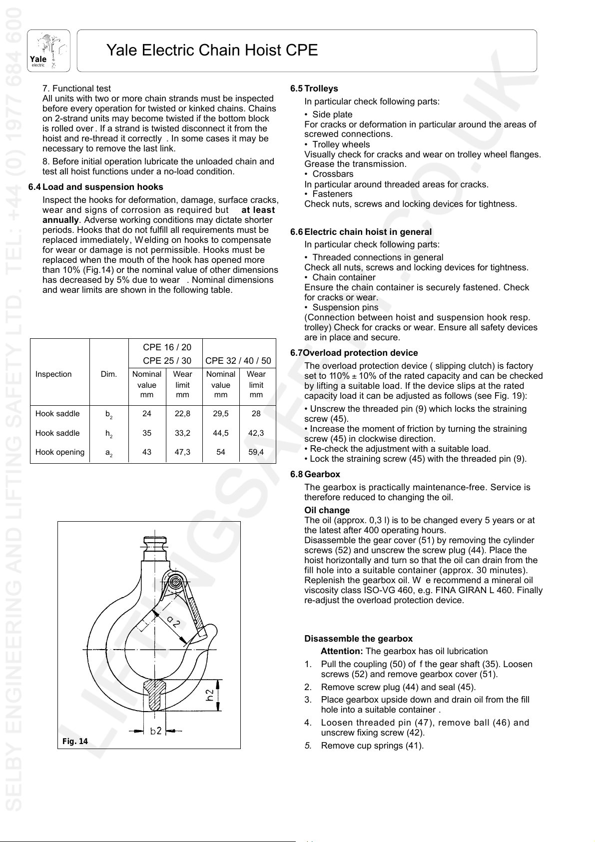
6.4 Load and suspension hooks
Inspect the hooks for deformation, damage, surface cracks,
wear and signs of corrosion as required but at least
annually. Adverse working conditions may dictate shorter
periods. Hooks that do not fulfill all requirements must be
replaced immediately, W elding on hooks to compensate
for wear or damage is not permissible. Hooks must be
replaced when the mouth of the hook has opened more
than 10% (Fig.14) or the nominal value of other dimensions
has decreased by 5% due to wear . Nominal dimensions
and wear limits are shown in the following table.
CPE 16 / 20
CPE 25 / 30 CPE 32 / 40 / 50
Inspection Dim. Nominal Wear Nominal Wear
value limit value limit
mm mm mm mm
Hook saddle b
Hook saddle h
Hook opening a
2
2
2
24 22,8 29,5 28
35 33,2 44,5 42,3
43 47,3 54 59,4
6.5 Trolleys
In particular check following parts:
• Side plate
For cracks or deformation in particular around the areas of
screwed connections.
• Trolley wheels
Visually check for cracks and wear on trolley wheel flanges.
Grease the transmission.
• Crossbars
In particular around threaded areas for cracks.
• Fasteners
Check nuts, screws and locking devices for tightness.
6.6 Electric chain hoist in general
In particular check following parts:
• Threaded connections in general
Check all nuts, screws and locking devices for tightness.
• Chain container
Ensure the chain container is securely fastened. Check
for cracks or wear.
• Suspension pins
(Connection between hoist and suspension hook resp.
trolley) Check for cracks or wear. Ensure all safety devices
are in place and secure.
6.7Overload protection device
The overload protection device ( slipping clutch) is factory
set to 110% ± 10% of the rated capacity and can be checked
by lifting a suitable load. If the device slips at the rated
capacity load it can be adjusted as follows (see Fig. 19):
• Unscrew the threaded pin (9) which locks the straining
screw (45).
• Increase the moment of friction by turning the straining
screw (45) in clockwise direction.
• Re-check the adjustment with a suitable load.
• Lock the straining screw (45) with the threaded pin (9).
6.8 Gearbox
The gearbox is practically maintenance-free. Service is
therefore reduced to changing the oil.
Oil change
The oil (approx. 0,3 l) is to be changed every 5 years or at
the latest after 400 operating hours.
Disassemble the gear cover (51) by removing the cylinder
screws (52) and unscrew the screw plug (44). Place the
hoist horizontally and turn so that the oil can drain from the
fill hole into a suitable container (approx. 30 minutes).
Replenish the gearbox oil. W e recommend a mineral oil
viscosity class ISO-VG 460, e.g. FINA GIRAN L 460. Finally
re-adjust the overload protection device.
Fig. 14
Disassemble the gearbox
Attention: The gearbox has oil lubrication
1. Pull the coupling (50) of f the gear shaft (35). Loosen
screws (52) and remove gearbox cover (51).
2. Remove screw plug (44) and seal (45).
3. Place gearbox upside down and drain oil from the fill
hole into a suitable container .
4. Loosen threaded pin (47), remove ball (46) and
unscrew fixing screw (42).
5. Remove cup springs (41).
10
Page 11

Yale Electric Chain Hoist CPE
Yale
electric
6. Loosen locking screw (38) and remove locking bolt (39).
7. Loosen snap ring (37), remove bearing plate (33) and
ball bearing (36). Remove snap ring (34) and press
ball bearing (36) out of bearing plate (33). Remoove
snap ring (37) from gear shaft (35).
8. Remove friction discs (28) and ring gear (29).
9. Remove planet gears (32), needle bearings (31), stop
washers (30) as well as planet gear carrier assy (27)
and pinion (26). Pull out gear shaft (35).
10. Remove threaded pin (17).
11. Press out remaining gears in the housing (1) in
direction of the flange. Light blows with a rubber
hammer in axial direction onto the rim of the housing
(flange side) may be helpful to loosen the bearing race
(15).
12. Remove planet gears (25), needle bearings (24) and
stop washers (23) from planet gear carrier (22).
13. Pull planet gear carrier (22) and pinion (21) out of planet
gear carrier (3).
14. Remove ball bearing (20) and bearing race (15) from
planet gear carrier (3).
15. Remove snap ring (11) from planet gear carrier (3) and
press out planet gear shaft (10).
16. Remove planet gears (7), needle bearings (8), stop
washers (6) and spacer rings (9).
15. Remove bearing (5) and packing rings (4).
After cleaning, inspection and replacement of all worn parts
re-assembly can be started.
Parts subject to wear are: stop washers (6, 23, 30), needle
bearings (8, 24, 31), O-rings and packing rings (4, 16, 18,
43) as well as the seal (45).
Reassemble the gearbox
Reassemble the gearbox in the reverse order strictly in
accordance with the sectional drawing.
Special care should be taken for clean and correct instal-
lation of planet gears (7) with needle bearings (8) in equal
sorting and stop washers (6) as well as spacer rings (9) in
the planet gear carrier (3).
The friction discs (28) on either side of the ring gear (29)
must be installed oil-soaked (leave in oil for 1 hour before
installation).
The exact adjustment of the overload device is only
possible when the hoist is completely reassembled. Pre-
adjustment of the cup spring (41) is made with the fixing
screw (42).
After the exact adjustment has been made, the fixing screw
(42) is secured by means of the ball (46) and the threaded
pin (47).
6.9 MOTOR
Motor
Under normal conditions the motor is practically main-
tenance-free. Every 2.1/2 years the bearings are to be
inspected, cleaned and repacked half-full with grease. We
recommend K 3 N / KL 3 N DIN 51825 / DIN 51502.
Disc brake
Service to the disc brake is reduced to checking and adjust-
ing the brake air gap. The disc brake air gap should be
between 0,2 and 0,6 mm (this guarantees a short reaction
time and low noise emission). When the wear and tear of
the brake lining comes down to the point where the max.
possible air gap has finally been reached, it is indispen-
sible to carry out a re-adjustment of the brake (the max.
permissible air gaps are shown in the table below).
3.1 Remove fan guard M14.
3.2 Loosen binding screws B14.
3.3 Remove O-ring B62 , insert spacer blocks B40 between
armature disc B42 und adhesive plate B16 (thickness
of the spacer blocks is to be found in the table below).
3.4 Tighten screws B31, or - in case of two shaft extensions
- nut B35 to an extent as to permit the removal of the
spacer blocks B40.
3.5 Evenly tighten the binding screws B14. Please tighten
first screw placed opposite of the fitting key (for the
permissible torque consult the table below).
3.6 Tighten screw B31 once more.
3.7 Remove spacer blocks B40.
3.8 Put on fan guard M14.
3.9 Make a test run for checking the brake funtion.
Attention: Do not allow the brake friction pads to come
into contact with lubricant or similar.
Fig. 15
1234567 891011
Type Nominal Fan B43 Spacer Air gap Pressure Tightening Tightening Adhesive Threaded Quantity
brake with brake block max. spring B9 torque torque plate pin of fitting
torque lining B40 (mm) (mm) colour for B14 for B6 B16 B71 plate B11
EBF 20,2 Nm WS 5907 - 0,6 no colour 7 - 9 Nm 7 + 0,5 Nm no M 5x80 0
11
Page 12

Yale
electric
Yale Electric Chain Hoist CPE
12
14
23
15
9
11
14
1
10
3
7
8
7
6
5
4
11
19
26
22
2
13
16
17
29
14
18
20
25
14
Fig. 16: Hoist body
12
Page 13

Yale Electric Chain Hoist CPE
Yale
electric
Yale Part No.
No. 16 20 25 30 32 40 50
Item Description Qty. CPE / F CPE / F CPE / F CPE / F CPE / F CPE / F CPE / F
1 Housing half - motor side 1 0608972 0608972 0608972 0608972 0608972 0608972 0608972
2 - gearbox side 1 0608974 0608974 0608974 0608974 0608974 0608974 0608974
1-11 Main frame assy.10609449 0609449 0609449 0609449 0609449 0609449 0609449
3 Chain guide 1 0608976 0608976 0608976 0608976 0608976 0608976 0608976
4 Chain stripper 1 0608978 0608978 0608978 0608978 0608978 0608978 0608978
5 Load sheave 1 0609374 0609374 0609374 0609374 0609374 0609374 0609374
6 Roll pin 2 9134001 9134001 9134001 9134001 9134001 9134001 9134001
7 Straight pin 2 9124169 9124169 9124169 9124169 9124169 9124169 9124169
- 2 speeds 1 0600117 0600117 0600117 0600117 0600117 0600117 0600117
8 Straight pin 2 9124111 9124111 9124111 9124111 9124111 9124111 9124111
9 Ball bearing 1 9151106 9151106 9151106 9151106 9151106 9151106 9151106
11 Cyl. screw 2 9102254 9102254 9102254 9102254 9102254 9102254 9102254
12 Brake motor - 1 speed 1 0600116 0600116 0600116 0600116 0600116 0600116 0600116
10 Cyl. screw 1 9102253 9102253 9102253 9102253 9102253 9102253 9102253
13
13 Planetary gear 1 0609678 0609678 0608814 0608814 0609678 0609678 0608814
14 Hex. screw 8 9101660 9101660 9101660 9101660 9101660 9101660 9101660
15 Suspension bolt 2 0609388 0609388 0609388 0609388 0609388 0609388 0609388
16 Bolt locking device 1 0609448 0609448 0609448 0609448 0609448 0609448 0609448
17 Cyl. screw 2 9102150 9102150 9102150 9102150 9102150 9102150 9102150
18 Screw plug 2 9110007 9110007 9110007 9110007 9110007 9110007 9110007
19 Screw plug 1 9192000 9192000 9192000 9192000 9192000 9192000 9192000
20 Screw plug 1 9192003 9192003 9192003 9192003 9192003 9192003 9192003
21 Screw plug 1 9192002 9192002 9192002 9192002 9192002 9192002 9192002
23 Safety latch kit 1 0408671 0408671 0408671 0408671 0408672 0408672 0408672
22-23 Suspension hook assy .10609393 0609393 0609393 0609393 0609517 0609517 0609517
- 2 speeds 1 0609615 0609998 0609457 0609745 0609615 0609999 0609457
25 Identity plate - 1 speed 1 0609614 0609996 0609456 0609744 0609614 0609997 0609456
26 Grooved nail 2 9128004 9128004 9128004 9128004 9128004 9128004 9128004
- Capacity decal 1 0609694 0600002 0609695 0609696 0609682 06000001 0609511
- Nameplate 2 0609692 0609692 0609692 0609692 0609692 0609692 0609692
29 Chain anchor bolt 1 ----0608855 0608855 0608855
Page 14

Yale
electric
Yale Electric Chain Hoist CPE
11
29
14
10
15
21
22
23
16
23
12
13
9
20
7
4
26
22
17
15
20
8
3
2
6
25
27
28
5
21
1
24
18
19
1- strand
Fig. 17: Bottom blocks
CPE / F 16
CPE / F 20
Item D escription Qty. CPE / F 25
No. CPE / F 30
1-8 Bottom block assy. 1600 kg 1 0609684
Bottom block assy. 2000 kg 1 0609993
Bottom block assy. 2500 kg 1 0609677
Bottom block assy. 3000 kg 1 0609909
1-2 Load hook assy.10408430
2 Safety latch kit10408671
3 Load hook coupling 1 0608851
4 Swivel tube 1600 kg 1 0609683
Swivel tube 2000 kg 1 0600003
Swivel tube 2500 kg 1 0609399
Swivel tube 3000 kg 1 0609908
5 Ball set (15 pcs. Ø 5) 1 0404767
6 Threaded pin 1 9114030
7 Snap ring 1 9139020
8 Chain bolt 1 0608855
9 Buffer 1 0609734
10-14 Chain end st op assy.10609995
10 Chain end stop half20608867
11 Cyl. screw 1 9102019
12 Lockwasher 1 9122032
13 Hex. nut 1 9115014
14 Buffer 1 0609734
2- strand
CPE / F 32
Item D escription Qty. CPE / F 40
No. CPE / F 50
15-23 Bottom block assy. 3200 kg 1 0609681
Bottom block assy. 4000 kg 1 0609994
Bottom block assy. 5000 kg 1 0609510
15 Swivel half 2 0609495
16 Idler sheave 1 0609505
17 Buffer 1 0601704
18 Capacity plate 3200 kg 2 0609682
Capacity plate 4000 kg 2 0600001
Capacity plate 5000 kg 2 0609511
19 Grooved nail Ø 3 x 4 8 9128004
20 Cyl. screw 2 9102053
21 Hex. nut 2 9115118
22 Needle bearing 2 9153083
23 Spacer 2 9121218
24-28 Load hook assy.10408434
25 Safety latch kit10408672
26-28 Crosshead assy. 1 0404850
27 Ball set (16 pcs. Ø 6) 1 0404799
28 Threaded pin 1 9114184
29 Load chain (specify length) 6109488
14
Page 15

Yale Electric Chain Hoist CPE
2
Yale
electric
3
1
Fig. 18: Chain Container
Item Description Qty. Yale Part No.
No. all models
1 Chain container assy
1 Chain container assy
2 Cyl. screw 1 9102255
3 Hex. nut 1 9115098
for 13 m linear chain length 1 6109467
for 21 m linear chain length 1 6109468
15
Page 16

Yale
electric
Fitted with Loctite 243
Yale Electric Chain Hoist CPE
Prior to assembly soak in oil for 1 hour
5900-6000 N
Pre-tension
of cup spring
Secure with Loctite 243
(after completion of clutch adjustment)
Transmission oil
0,3 kg
Fina Geran L460
16
Fig. 19: Gearbox
Page 17

Yale Electric Chain Hoist CPE
Yale
electric
Item Description Qty. Model
No. CPE 30-5
- Planet gearbox assy. 1 0600230
1 Gearbox housing 1 0600237
2 Ring 1 0600238
3 Planet gear carrier 1 0600239
4 Packing ring 1 9172110
5 Bearing 1 9150043
6 Stop washer 6 9153043
7 Planet gear 3 0600240
8 Needle bearing 6 9153090
9 Spacer ring 3 0600241
10 Planet gear shaft 3 0600242
11 Snap ring 1 9129070
13 Ring 1 0600243
14 Snap ring 1 9129071
15 Bearing race 1 0600244
16 O-ring 1 9171352
17 Threaded pin 1 9114134
18 Packing ring 1 9172112
19 Washer 1 9121234
20 Ball bearing 1 9151101
Item Description Qty. Model
No. CPE 30-5
27.2 Planet gear shaft 3 0600253
28 Friction disc 2 0600254
29 Ring gear 1 0600255
30 Stop washer 3 9153043
31 Needle bearing 3 9153090
32 Planet gear 3 0600171
33 Bearing plate 1 0600256
34 Snap ring 2 9130034
35 Gear shaft 1 0600257
36 Ball bearing 1 9150043
37 Snap ring 2 9129029
38 Locking screw 1 0600258
39 Locking bolt 1 0600259
40 O-ring 1 9171169
41 Cup spring 4 9120041
42 Fixing screw 1 0600260
43 O-ring 1 9171170
44 Screw plug 1 9110052
45 Seal 1 9179004
46 Ball 1 9159011
21 Pinion 1 0600245
22 Planet gear carrier assy. 1 0600246
22.1 Carrier disc 1 0600247
22.2 Planet gear shaft 3 0600248
23 Stop washer 3 9153043
24 Needle bearing 3 9153090
25 Planet gear 3 0600249
26 Pinion 1 0600250
27 Planet gear carrier assy. 1 0600251
27.1 Carrier disc 1 0600252
Attention: When ordering spare parts always indicate serial number and mfg. year of hoist
47 Threaded pin 1 9114136
48 Fitting plate 1 9121056
50 Coupling 1 0608879
51 Gear box cover 1 0600262
52 Screw 4 9102019
17
Page 18

Yale
electric
Yale Electric Chain Hoist CPE
Fig. 20: Motor
Item Description Qty.
No. 1-speed 2-speed
- Motor assy. 1 0600116 0600117
1 .. Stator 1 0600185 0600196
2 .. Rotor 1 0600186 0600197
3 .. Bearing plate, A-side 1 0600187 0600187
4 .. Bearing plate, B-side 1 0600188 0600188
7 .. Fan cover 1 0600189 0600189
8 .. Terminal box assy. 1 0600190 0600190
(board, box, box cover
box seal)
9 .. Rectifier 1 0600110 0600110
16 .. Armature disc 1 0600113 0600113
17 .. Brake fan 1 0600112 0600112
18 .. Fitting parts set for mounting1 0600194 0600194
the brake ( brake spring, O-ring,
cap screw , washers, fitting key)
CPE CPEF
19 .. Manual brake release system
(optional) 1 0600195 0600195
Attention: When ordering spare parts always indicate serial number and mfg. year of hoist
18
Page 19

Yale Electric Chain Hoist CPE
30
32
24
15 + 18
29
17
29
22
24
21
16
19
18
1
15
Yale
electric
2
9
10
11
12
12
3
5
28
1
7
4
6
8
Fig. 22: Contactor control
Item Description Qty. Yale Part No.
No. all models
1 Housing 1 0609810
2 Mounting plate 1 0609792
3 Screw 4 9108018
4Reversing starter 1 0609558
5 Screw 4/8* 9107005
6 Transformer 1 0719737
7 Fine-wire fuse 1 9190126
8 Screw 4 9107032
9 Fuse carrier 2 0609808
10 Fine-wire fuse 2 9190128
11 Terminal 6/7* 0609811
12 PE conductor terminal 2 0609812
Name tag 110609813
Name tag 210609814
Name tag 310609815
27
Item Description Qty. Yale Part No.
No. all models
15 Screw fitting 3 9184082
16 Screw fitting 1 9184081
17 Counter-nut 1 9184085
18 Counter-nut 3 9184086
19 Plate 1 0609788
20 Screw 2 9103013
21 Washer29121001
22 Cyl. screw 4 9107023
23 Connecting cable (CPE only) 1* 0609828
Connecting cable (CPEF only) 1* 0609829
24 Rope clamp20605355
25 Tension relief wire 1 0609561
26 Control cable (CPE only) 1 0606562
Control cable (CPEF only) 1* 0609563
27 Control switch (CPE only) 1 0609566
Name tag 410609816
Name tag L1 1 0609817
Name tag L2 1 0609818
Name tag L3 1 0609819
Name tag PE 1 0609820
Name tag 3 0609821
Name tag F5 1 0609822
Name tag F6 1 0609823
Control switch (CPEF only) 1 0609567
28 Wiring diagram (CPE only) 1 0609571
Wiring diagram (CPEF only) 1 0609572
29 Tape 5 9181113
30 Fastener 1 0608882
31 Hex. Screw 1 9101661
32 Washer19121006
33 Contactor 1* 0609574
19
Page 20

Yale
electric
Yale Electric Chain Hoist CPE
5
6
8
7
Fig. 23: Direct control
4
9
10
2
1
Item Description Qty.
No. 1-speed 2-speed
1 Pendant control assy
with emergency stop 1 0609454 0609455
2 Control cable (specify length) - 9062407 9062407
3Wiring diagram 1 0609631 0609632
4 Clamp 2 0605355 0605355
5Screw fitting 1 9184082 9184082
6Screw fitting 1 9184084 9184084
7Fastener 1 0608882 0608882
8 Hex. screw 1 9101661 9101661
9 Washer19121006 9121006
10 Strain relief (specify length) - 9093001 9093001
CPE CPEF
20
Page 21

Yale Electric Chain Hoist CPE
Yale
electric
7
6
5
3
10
9
Fig. 24: Pendant switch for direct control
8
2
4
11
1
tem Description Qty.
I
No. 1-speed 2-speed
- Pendant control assy .
with emergency stop 1 0609454 0609455
1 Contact element 1 0609686 0609687
2 Carrier for contact element 1 0609965 0609965
3 Lowering button DN 1 0609966 0609967
Lifting button UP 1 0609968 0609969
4 Contact element emerg. stop 1 0609978 0609978
5 Emergency stop button 1 0609977 0609977
6 Rubber bushing 1 0609970 0609970
7 Loop for tension re lief device 1 0609971 0609971
8 Clamping piece 1 0609972 0609972
9Interlocking lever 1 0609973 0609973
10 Front housing 1 0609974 0609974
11 Rear housing 1 0609975 0609975
CPE CPEF
21
Page 22

Yale
electric
Yale Electric Chain Hoist CPE
2
4
1
3
Fig. 25: Pendant switch for contactor control
I
tem Description Qty.
No. 1-speed 2-speed
- Pendant control assy .
with emergency stop 1 0609566 0609567
1 Contact element 1 0609980 0609981
2 Emergency stop button 1 0609984 0609984
3 Lowering button DN 1 0609985 0609986
Lifting button UP 1 0609987 0609988
4 Contact element emerg. stop 1 0609982 0609983
CPE CPEF
22
Page 23

Yale Electric Chain Hoist CPE
Yale
electric
13
12
8
7
6
2
10
9
8
5
6
7
10
11
9
5
15
15
4
5
9
11
10
1
4
14
5
7
6
8
9
11
3
Fig. 26: Plain Trolley
I
tem Description Qty. Yale Part No.
No. all models
1Side plate10559163
2Side plate10559167
3Roll pin 4 9134120
4Crossbar - beam range A 2 0559169
Crossbar - beam range B 2 0559170
5 Round nut 4 0559168
6Washer 4 9121213
7 Hex. nut 4 9115156
6
10
7
8
Item Description Qty. Yale Part No.
No. all models
8 Locking nut 4 9115155
9Trolley wheel 4 0508210
10 Ball bearing 8 9151079
11 Snap ring 4 9129003
12 Identity plate 1 0559869
13 Grooved nail49128004
14 Centre traverse 1 0559353
15 Roll pin 2 9134002
23
Page 24

Yale
electric
Yale Electric Chain Hoist CPE
1
3
2
18
14
6
13
4
5
Fig. 27: Geared trolley drive (for other parts see Fig. 26)
12
6
7
8
9
15
10
11
17
16
tem Description Qty. Yale Part No.
I
No. all models
1 Geared trolley wheel 2 0508214
2 Ball bearing 8 9151079
3 Snap ring 4 9129003
4 Support 1 0508229
5 Spacer tube 1 0719111
6 Lockwasher 4 9122016
7 Hex. screw 2 9101050
8 Bushing 1 0102503
9 Spacer 4 9121205
Item Description Qty. Yale Part No.
No. all models
10 Hand chain guide 1 0558062
11 Hex. screw 2 9101014
12 Hex. nut 2 9115148
13 Drive shaft 1 0719671
14 Roll pin 1 9134052
15 Hand chain wheel 1 0558061
16 Hand chain (specify length) 4307654
17 Connecting link 1 0404733
18 Side plate 1 0559165
24
Page 25

Yale Electric Chain Hoist CPE
22
20
Yale
electric
1
2
21
15
3
17
16
23
14
10
13
Fig. 28: Electric trolley drive (for other parts see Fig. 26)
11
4
5
18
12
19
8
7
6
9
I
tem Description Qty. Yale Part No.
No. all models
1 Geared trolley wheel 2 0508214
2 Ball bearing 8 9151079
3 Snap ring 4 9129003
4 Worm gear 1 0719764
5 Flange 1 0719371
6Drive shaft 1 0719372
7Fitting key 1 9131072
8 Needle bearing 1 9153077
9 Snap ring 1 9129016
10 Hex screw 4 9101170
11 Lockwasher 4 9122003
12 Roll pin 1 9134080
Item Description Qty. Yale Part No.
No. all models
13 Hex. nut 2 9101014
14 Lockwasher 2 9122004
15 Spacer 7 9121215
16 Pinion 1 0719373
17 Snap ring 1 9123038
18 Screw fitting 1 9184082
19 Brake motor - 1 speed 1 0609586
- 2 speeds 1 0609587
20 Reducing sleeve 1 0719868
21 Bushing 1 0719870
22 Hex. screw 4 9101439
23 Side plate 1 0559165
25
Page 26

Yale
electric
Yale Electric Chain Hoist CPE
11
12
15
7
16
1
13
14
2
4
3
6
10
9
5
8
Fig. 29: Pendant switch for electric hoist with electric trolley (direct and contactor control)
Pendant switch for direct control Pendant switch for contactor control
Item Description Qty. Hoist 1G Hoist 2G Hoist 2G Hoist 1G Hoist 1G Hoist 2G Hoist 2G Hoist 1G
No. Trolley 1G Trolley 2G Trolley 1G Trolley 2G Trolley 1G Trolley 2G Trolley 1G Trolley 2G
1-18 Control switch assy . 1 0609610 0609611 0609832 0609833 0609612 0609613 0609806 0609807
1 Contact element hoist 1 0609686 0609687 0609687 0609686 0600032 0600034 0600034 0600032
Contact element hoist 1 - - - - 0600033 - - 0600033
2 Contact element trolley 1 0600022 0600029 0600022 0600029 0600032 0600034 0600032 0600034
Contact element trolley1 ----0600033 - 0600033 -
3 -button DN, hoist 1 0600023 0600030 0600030 0600023 0600023 0600030 0600030 0600023
4 -button UP, hoist 1 0600024 0600031 0600031 0600024 0600024 0600031 0600031 0600024
5 -button LEFT, trolley 1 0600023 0600030 0600023 0600030 0600023 0600030 0600023 0600030
6 -button RIGHT, trolley 1 0600024 0600031 0600024 0600031 0600024 0600031 0600024 0600031
7 Contact element em. stop 1/2* 0609978 0600032
8-10 Housing assy. without
contacts and buttons 1 0600028 0600035
8 Front housing 1 on request
9 Housing centre part 1 on request
10 Rear housing 1 on request
11 Rubber bushing 1 0600025
12 Clamping piece 1 0609972
13 Interlocking lever 2 0609973
14 Dust cap 1 0600026
15 Rubber bushing support 1 0600027
16 Emergency stop bu tton 1 0609977
* for contactor control only 1G = 1 speed; 2G = 2 speeds
26
Page 27

Yale Electric Chain Hoist CPE
1
Yale
electric
33
Zuleitung
31
12
11
6
10
13
17
26
28
27
3
7
14
23
2
6
6
8
32
18
24
22
16
24
29
30
trolley
Cable conductor
Cable conductor
15
hoist
9
16
32
23
20
19
Fig. 30: Contactor control CPE/F with VTE/F
Item Description Qty. Yale Part No.
No. all models
1Plate 1 0719732
2 Screw 2 9103005
3 Housing 1 0719722
4 Mounting plate 1 0719721
5 Screw 4 9108018
6Screw fitting 4 9184082
7 Counter-nut 4 9184086
8Contactor 2 0609558
9 Screw 8 9107005
10 Transformer 1 0719760
11 Screw 4 9107011
12 Fine-wire fuse 1 9190129
13 Fuse terminal 2 0609808
14 Fine-wire fuse 2 9190130
15 Terminal 8 0609811
16 Ground terminal 2 0609812
17 Name tag 110609813
Name tag 210609814
Name tag 310609815
Name tag 510609848
Item Description Qty. Yale Part No.
No. all models
Name tag 3 0609821
Name tag F5 1 0609822
Name tag F6 1 0609823
18 Wiring diagram CPE+VTE 1 0609854
Wiring diagram CPEF+VTE 1 0609856
Wiring diagram CPE+VTEF 1 0609855
Wiring diagram CPEF+VTEF 1 0609853
19 Identity plate 1 0719680
20 Control switch CPE+VTE 1 0609612
Control switch CPEF+VTE 1 0609806
Control switch CPE+VTEF 1 0609807
Control switch CPEF+VTEF10609613
21 Control cable (for 3 m lift) 1 0609899
22 Strain relief cord (2,4 m) 1 9093001
23 Rope clamp20605355
24 Tape (specify length) 9181113
25 S-hook 1 0717029
26 Support 1 0719742
27 Cyl. screw 1 9102026
28 Lockwasher 1 9122031
Name tag 610609849
Name tag L1 1 0609817
Name tag L2 1 0609818
Name tag L3 1 0609819
Name tag PE 1 0609820
* only CPEF + VTEF
29 Cable conductor trolley10609898
30 Cable conductor hoist 1 0609897
31 Screw 4 9107023
32 Contactor (2nd speed only) 1/2* 0609574
33 Power supply cable 1 -
27
Page 28

Yale
electric
Yale Electric Chain Hoist CPE
1
3
4
23
28
Zuleitung
5
6
2
12
25
24
22
20
7
21
12
26
9
11
27
13
16
19
18
21
20
15
17
Cable conductor trolley
Cable conductor hoist
Fig. 31: Direct control CPE/F with VTE/F
Item D escription Qty. Yale Part No.
No. all models
1Plate 1 0719741
2 Screw 2 9103005
3 Housing 1 0609878
4 Screw 4 9107023
5Carrier 1 0609877
6 Screw 2 9108018
7Screwed fitting 3 9184082
8 Counter-nut 3 9184086
9Screwed fitting 1 9184088
10 Counter-nut 1 9184087
11 Terminal 11 0609811
12 Ground terminal 2 0609812
13 Name tag 110609813
Name tag 210609814
Name tag 310609815
Name tag 410609816
Name tag 510609848
Name tag 910609872
Name tag 10 1 0609873
Name tag 11 1 0609874
Item D escription Qty. Yale Part No.
No. all models
15 Wiring diagram CPE + VTE 1 0609882
Wiring diagram CPEF + VTE 1 0609883
Wiring diagram CPE + VTEF 1 0609884
Wiring diagram CPEF + VTEF 1 0609885
15 Name plate 1 0719680
17 Control switch CPE + VTE 1 0609610
Control switch CPEF + VTE 1 0609832
Control switch CPE + VTEF 1 0609833
Control switch CPEF + VTEF 1 0609611
18 Control cable for 3 m lift 1 0609890
19 Strain relief cord (2,4 m) 1 9093001
20 Clamp 2 0605355
21 Tape (specify length) 9181113
22 S-hook 1 0717029
23 Support 1 0719742
24 Cyl. screw 1 9102026
25 Lockwasher 1 9122031
26 Cable conductor trolley 1 0609879
27 Cable conductor hoist 1 0609888
28 Power supply cable 1 ---
Name tag L1 1 0609817
Name tag L2 1 0609818
Name tag PE 1 0609819
Name tag 3 0609821
Control cable (m) CPE+VTE 1 9062403
Control cable (m) CPEF+VTEF 1 9062403
Strain relief cord (specify length) 9093001
28
Page 29

Yale Electric Chain Hoist CPE
Yale
electric
29
Page 30

Yale
electric
Yale Electric Chain Hoist CPE
Inspection Chart
Inspection before initial operation:
by:
Date of initial operation:
Regular Inspections
Date Findings Repair Test
Date by *
* competent person
30
Page 31

Yale Electric Chain Hoist CPE
EC DECLARATION OF CONFORMITY
Yale
electric
in accordance with Machinery Directive 98/37/EEC (Appendix II A)
We,
Yale Industrial Products GmbH
D-42549 Velbert, Am Lindenkamp 31
hereby declare, that the design, construction and commercialized execution of the below mentioned machine complies
with the essential health and safety requirements of the EC Machinery Directive. The validity of this declaration will
cease in case of any modification or supplement not being agreed with us previously.
Furthermore, validity of this declaration will cease in case that the machine will not be operated correctly and in
accordance with the operating instructions and/or not be inspected regularly.
Machine description: Electric chain hoist CPE/ F
Mod. CPE/F 16-8, Mod. CPE/F 20-8, Mod. CPE/F 25-5,
Mod. CPE/F 30-5, Mod. CPE/F 32-4, Mod. CPE/F 40-4,
Mod. CPE/F 50-2
Capacity 1600 - 5000 kg
Machine type: Electric chain hoist
Serial number: from manufacturing year 1/95
(Serial numbers for the individual capacities/models are registered
in the production book with the remark CE-sign)
Relevant
EC Directives: EC Machinery Directive 98/ 37/EEC
Transposed harmonised
standards in particular: EN 292, part 1 (safety of machines)
EN 292, part 2 (safety of machines)
EN 349 (safety of machines)
EN 818, part 1 (round link chain)
EN 818, part 4 (round link chain)
Transposed (either complete FEM 9.671; DIN 5684 (Lastketten)
or in extracts) national FEM 9.681 (Fahrmotoren)
standards and technical FEM 9.682 (Hubmotoren)
specifications in particular: FEM 9.755 (Betriebsdauer)
FEM 9.511 (Triebwerkseinstufung)
DIN 15018 (Krane)
DIN 15400 (Lasthaken für Hebezeuge)
DIN 15404 (Lasthaken für Hebezeuge)
VDE 0100 / Teil 726; VDE 0113 / EN 60204
BGV D6 (Krane)
BGV D8 (Winden, Hub- und Zuggeräte)
VBG 9.a (Lastaufnahmemittel)
ZH 1/27 (Prüfung von Kranen)
ZH1/25 (Prüfung von Hubgeräten)
Quality assurance: DIN EN ISO 9001 (Certificate Registration No.: 151)
Date / Manufacturer’s
authorized signature: 20.09.2002 ________________________
Identification of the signee: Dipl.-Ing. Andreas Oelmann
Manager Quality Assurance
31
Page 32

Yale
electric
Yale Electric Chain Hoist CPE
Quality engineered
and performance tested -
recognisably
32
 Loading...