

Page 1

PCC-2000 REFERENCE BOOK
PCC-2000
R
EFERENCE
The PCC-2000 allows you to quickly and easily operate the Yaesu
FT-2000/D HF/50 MHz Transceiver from your personal computer.
IMPORTANT NOTE
By using this software, you acknowledge that the Software is not intended for use in connection with any
high risk of personal injury or strict liability activity (including, without limitation to, air travel, space
travel, fire fighting, police operations, power plant operation, military operations, rescue operations, hospital and medical operations) and that Vertex Standard makes no warranty and shall have no liability in connection with any use of the Software in such situations.
All title and copyrights in and to the Software (including but not limited to any data, images, text, and other
components), and the accompanying printed materials, are owned by Vertex Standard. The Software is
protected by copyright laws and international treaty provisions, including U.S. federal criminal law. Vertex
Standard and YAESU are trademarks of Vertex Standard.
B
OOK
Vertex Standard expressly disclaims any warranty for the Software and Services. The Software and Services and any related documentation are provided “AS IS” without warranty of any kind, either express or
implied, including, without limitation, the implied warranties or merchantability, fitness for a particular
purpose, security, or noninfringement. The entire risk arising out of use or performance of the Software and
the Services remains with you.
- 1 -
Page 2

PCC-2000 REFERENCE BOOK
TABLE OF CONTENTS
PCC-2000 System Components .................................... 3
FT-2000 and Computer Interconnections ...................... 3
“PCC-2000” Personal Computer Controller Window ... 3
Opening/Closing the PCC-2000 Controller Program ... 4
Data Connection ............................................................ 4
Switching Power On/Off of the FT-2000 ...................... 4
AF Gain Control ............................................................ 4
SQL Level Control ........................................................ 4
Frequency Navigation on the Main Band (VFO-A) ..... 5
Frequency Navigation on the Sub Band (VFO-B) ........6
MODE Switch ............................................................... 7
Clarifier Operation ........................................................ 7
Audio Playback Feature ................................................ 7
Voice Memory Feature .................................................. 8
Antenna Selection .......................................................... 8
IPO (Intercept Point Optimization) ............................... 8
ATT (Attenuator) ........................................................... 8
RF Gain Control ............................................................ 9
VRF (Variable RF Front-end Filter) Operation ............. 9
Roofing Filter Selection ................................................ 9
CONTOUR Filter /
APF (Audio Peak Filter) Operation ................... 9
IF SHIFT Operation .................................................... 10
WIDTH Operation ....................................................... 10
NOTCH Operation ...................................................... 10
AUTO NOTCH Operation .......................................... 10
Noise Reduction Operation ......................................... 10
NAR (One-Touch Narrow IF Filter Selection) ........... 11
Noise Blanker Operation ............................................. 11
AGC ............................................................................. 12
LOCK Feature ............................................................. 12
VOX Operation ........................................................... 12
Using the Speech Processor ........................................ 13
Using the Monitor ....................................................... 13
Antenna Tuner Operation ............................................ 13
Repeater Operation ...................................................... 14
Parametric Microphone Equalizer Adjustment ........... 15
Keyer Operation .......................................................... 16
Contest Memory Keyer ............................................... 17
Rotator Control ............................................................ 17
QMB Memory ............................................................. 17
Operation of Miscellaneous Knobs and Buttons ......... 18
[
METER] Knob ..................................................... 18
[
MIC] Knob ........................................................... 18
[
RF PWR] Knob ................................................... 18
[
DIM] Button..........................................................18
[
MOX] Button ........................................................ 18
[
SPOT] Button ...................................................... 18
[A]
Button .............................................................. 18
[B]
Button .............................................................. 18
[
SPLIT] Button ...................................................... 19
[
TXW] Button ........................................................ 19
Main [RX] Button .................................................. 19
Main [TX] Button .................................................. 19
Sub [RX] Button .................................................... 19
Sub [TX] Button .................................................... 19
[
FAST] Button ....................................................... 20
[
AXB] Button ....................................................... 20
X
[
A
B] Button ........................................................ 20
W
[
V/M] Button .......................................................... 20
[
MXA] Button ....................................................... 20
[
AXM] Button ....................................................... 20
Main (VFO-A) [BAND] Button ............................20
Main (VFO-A) [MHz] Button ............................... 20
[
GRP] Button ........................................................ 20
[
MCH] Button ........................................................ 20
Sub (VFO-B) [BAND] Button .............................. 21
Sub (VFO-B) [MHz] Button .................................. 21
[
FAST] Button ....................................................... 21
[
A/B] Button .......................................................... 21
[
DISPLAY] Button ................................................21
Menu Operation ........................................................... 22
Command Send ........................................................... 23
Function Key Operation .............................................. 24
- 2 -
Page 3
PCC-2000 REFERENCE BOOK
PCC-2000 SYSTEM COMPONENTS
IBM® PC / compatible Computer with Microsoft® Windows® 2000, XP, or Vista
30 MB of available Hard Disk space
256 MB or more RAM
RS-232C port
1024 x 768 color display with 256-bit color support on the video card
RS-232C “Straight” Cable, DB9-pin Female to DB9-pin Female (Or, USB to RS-232C Adapter CableÚ).
: SomeUSB to RS-232C Adapter Cable does not function normally.
Ú
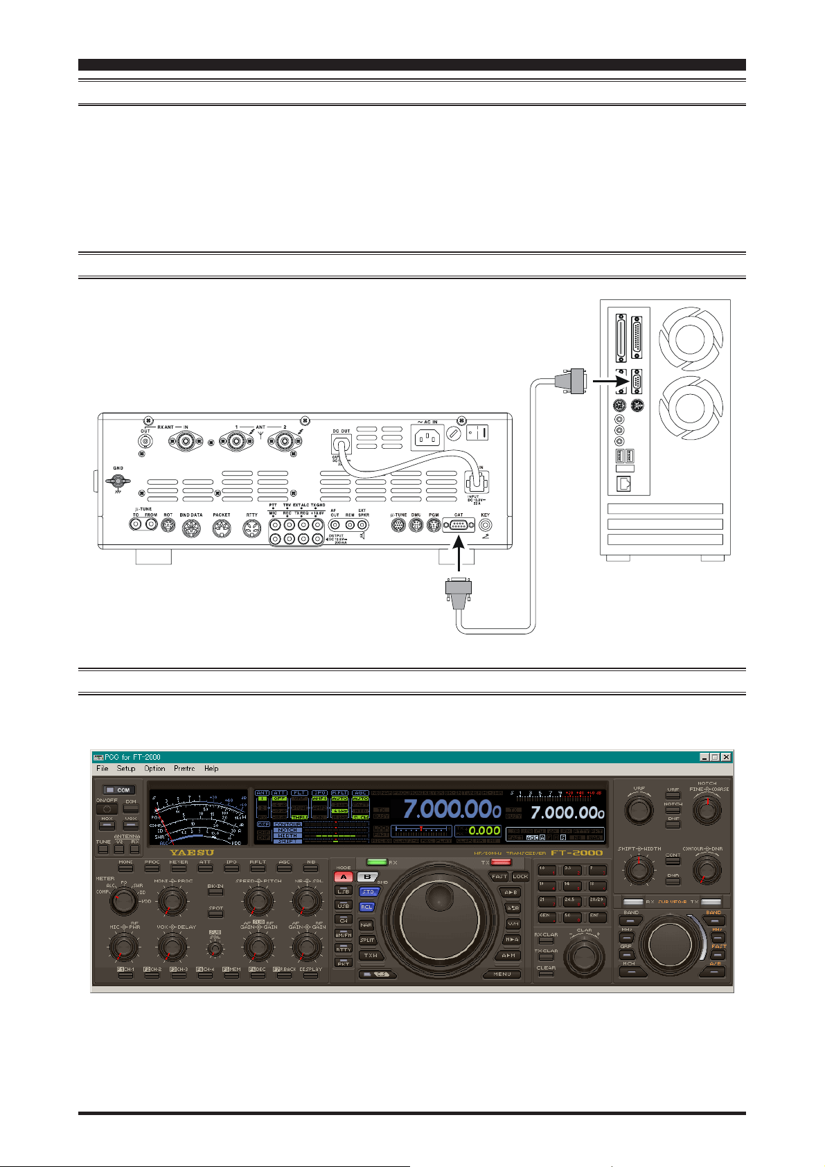
FT-2000 AND COMPUTER INTERCONNECTIONS
COM
T
A
C
RS-232C “Straight” Cable
“PCC-2000” PERSONAL COMPUTER CONTROLLER WINDOW
If you double-click the left mouse button on each knob or switch of the following illustration, jump to the detailed page of
the selected knob or switch.
- 3 -
Page 4
PCC-2000 REFERENCE BOOK
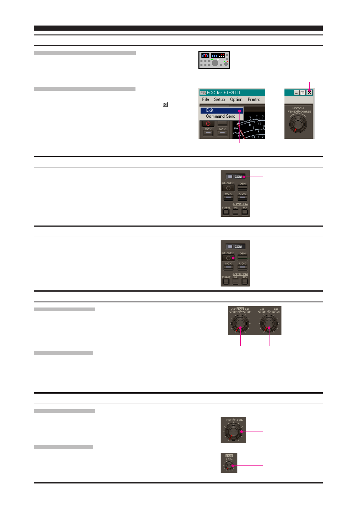
OPENING/CLOSING THE PCC-2000 CONTROLLER PROGRAM
OPENING THE PCC-2000 PROGRAM
Double click the left mouse button on the “PCC-2000” icon. The
“Vertex Standard” logo will appear for three seconds; afterwards
the “PCC-2000” Personal Computer Controller will be opened.
CLOSING THE PCC-2000 PROGRAM
To close the “PCC-2000” Personal Computer Controller:
Click the left mouse button on the Close Button “ ” on the
“PCC-2000” Personal Computer Controller.
Click the left mouse button on the “Exit” parameter in the
“File” menu on the “PCC-2000” Personal Computer Controller.
Press the [ESC] button on the keyboard.
DATA CONNECTION
“PCC-2000” icon
“EXIT” parameter
Close button
Click the left mouse button on the [COM] button of the “PCC-
2000” Personal Computer Controller to enable computer control. The yellow indicator will glow.
Click the left mouse button on the [COM] button of the “PCC-
2000” Personal Computer Controller again to disable computer control. The yellow indicator will go out.
SWITCHING POWER ON/OFF OF THE FT-2000
Click the left mouse button on the [ON/OFF] button of the “PCC2000” Personal Computer Controller to turn the transceiver “On”
and “Off.”
Note: the transceiver’s rear panel Power switch must already have
been turned on manually.
AF GAIN CONTROL
MAIN BAND (VFO-A
Click the left mouse button on the main [AF GAIN] knob (this
turns the color of the “AF GAIN” image yellow), then turn the
mouse scroll or press the left/right buttons to adjust the audio for
a comfortable listening level.
)
[
COM] button
[
ON/OFF] button
SUB BAND (VFO-B
Click the left mouse button on the sub [AF GAIN] knob (this
turns the color of the sub “AF GAIN” image yellow), then turn
the mouse scroll or press the left/right buttons to adjust the audio
for a comfortable listening level.
)
SQL LEVEL CONTROL
MAIN BAND (VFO-A
Click the left mouse button on the [SQL] knob (this turns the
color of the “SQL” image yellow), then turn the mouse scroll, or
press the left/right buttons, to adjust the squelch threshold level.
SUB BAND (VFO-B
Click the left mouse button on the sub [SQL] knob (this turns the
color of the sub “SQL” image yellow), then turn the mouse scroll,
or press the left/right buttons, to adjust the squelch threshold level.
)
)
- 4 -
Main [AF GAIN] knobSub [AF GAIN] knob
Main [SQL] knob
Sub [SQL] knob
Page 5
PCC-2000 REFERENCE BOOK
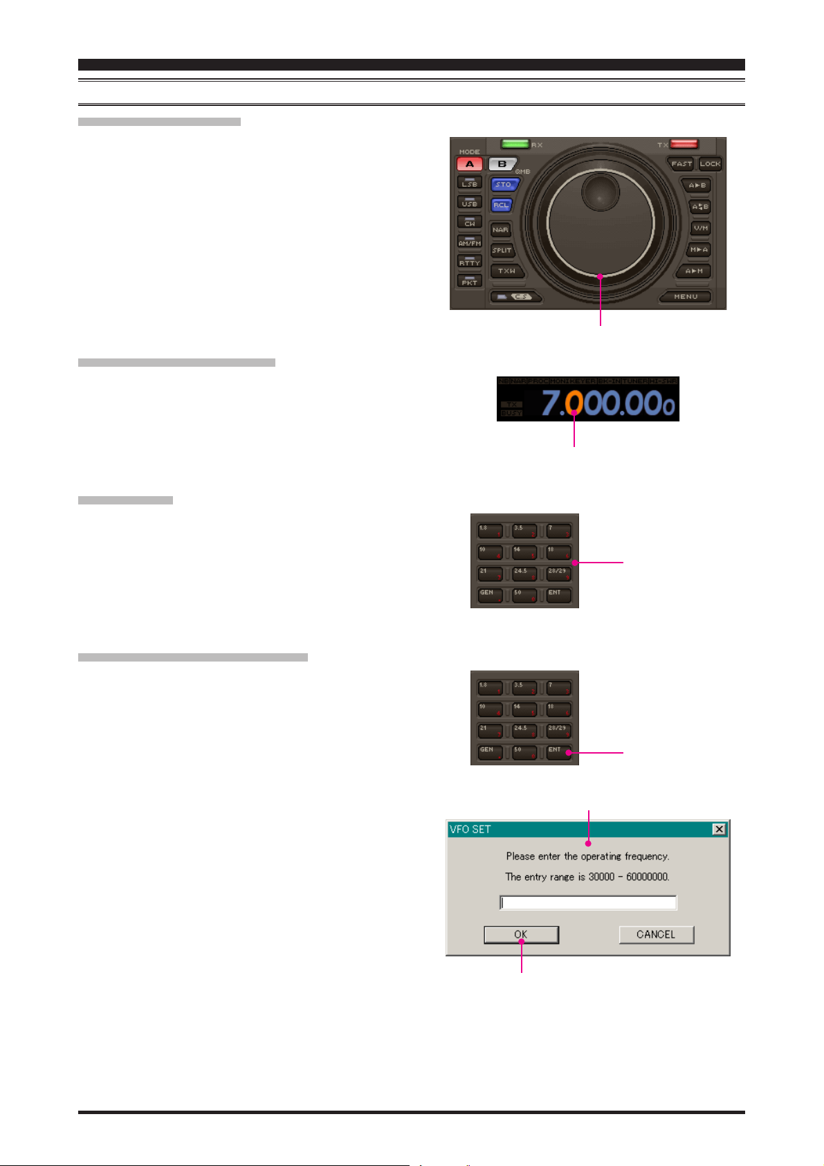
FREQUENCY NAVIGATION ON THE MAIN BAND (VFO-A
MAIN TUNING DIAL KNOB
Bring the mouse cursor to the Main Tuning Dial knob, then
turn the mouse scroll to tune the Main Band (VFO-A) frequency.
Press and hold in the left mouse button on the edge of the
Main Tuning Dial knob, then rotate the mouse, to tune the
Main Band (VFO-A) frequency while holding in the left
mouse button.
DIRECT FREQUENCY DIGIT SET
1. Click the left mouse button on the frequency digit which you
wish to change on the Main Band (VFO-A) frequency. The
frequency digit will change to Orange.
2. Turn the mouse scroll to tune the frequency digit of the Main
Band (VFO-A) frequency.
)
Main Tuning Dial knob
Frequency Digit
BAND CHANGE
Click the left mouse button on the [BAND] button corresponding to the Amateur on which you wish to operate.
DIRECT KEYPAD FREQUENCY ENTRY
1. Click the left mouse button on the [ENT] button of the BAND
keys. The “VFO SET” window will open.
2. Enter a frequency directly from the BAND keys or computer’s
keyboard. Available entry values are 30000 - 60000000 (300
Hz - 60 MHz).
3. Click the left mouse button on the [OK] button of the “VFO
SET” window or press the computer’s [ENTER] key to terminate the frequency entry.
BAND keys
[
ENT] button
“VFO SET” window
- 5 -
[OK]
button
Page 6
PCC-2000 REFERENCE BOOK
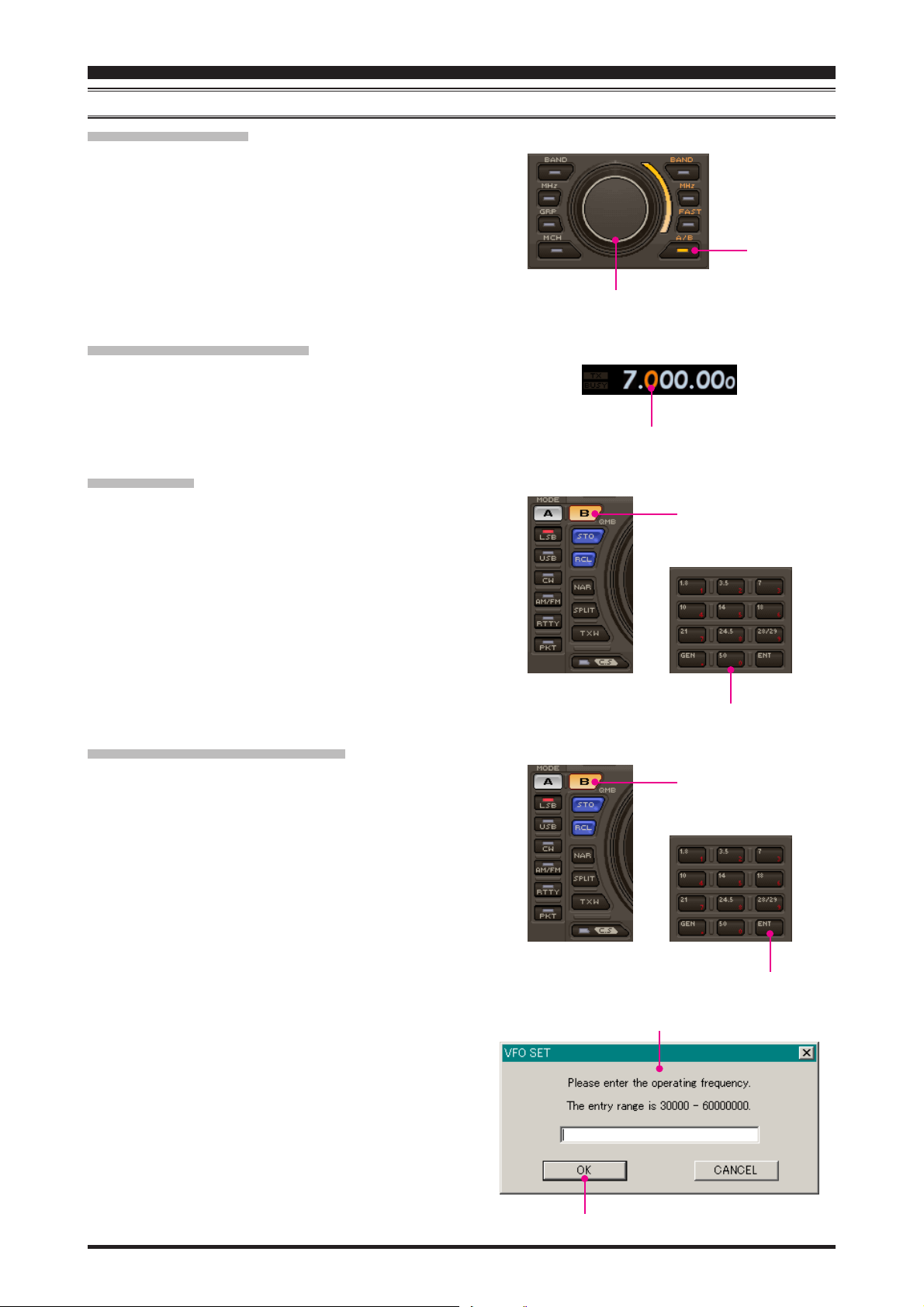
FREQUENCY NAVIGATION ON THE SUB BAND (VFO-B
[
SUB VFO-B] KNOB
Click the left mouse button on the [A/B] button to enable the
[
SUB VFO-B] knob. Bring the mouse cursor to the [SUB
VFO-B] knob, then turn the mouse scroll to tune the Sub
Band (VFO-B) frequency.
Click the left mouse button on the [A/B] button to enabling
the [SUB VFO-B] knob. Press and hold in the left mouse
button on the edge of the [SUB VFO-B] knob, then rotate
the mouse, to tune the Sub Band (VFO-B) frequency while
holding in the left mouse button.
DIRECT FREQUENCY DIGIT SET
1. Click the left mouse button on the frequency digit which you
wish to change on the Sub Band (VFO-B) frequency. The
frequency digit will change to Orange.
2. Turn the mouse scroll to tune the frequency digit of the Sub
Band (VFO-B) frequency.
BAND CHANGE
Click the left mouse button on the [B] button, then click the left
mouse button on the [BAND] button corresponding to the Amateur band on which you wish to operate.
[
SUB VFO-B] knob
Frequency Digit
[B]
)
button
[
A/B] button
DIRECT KEYPAD FREQUENCY ENTRY
1. Click the left mouse button on the [B] button, then click the
left mouse button on the [ENT] button of the BAND keys.
The “VFO SET” window will open.
2. Enter a frequency directly by the BAND keys or computer’s
keyboard. Available entry values are 30000 - 60000000 (300
Hz - 60 MHz).
3. Click the left mouse button on the [OK] button of the “VFO
SET” window or press the computer’s [ENTER] key to terminate the frequency entry.
BAND keys
[B]
button
“VFO SET” window
[
ENT] button
- 6 -
[OK]
button
Page 7
PCC-2000 REFERENCE BOOK
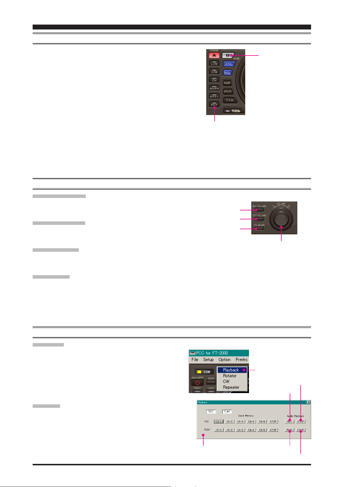
MODE SWITCH
Click the left mouse button on the [MODE] button to select
the desired operating mode for the Main band (VFO-A).
Click the left mouse button on the [B] button, then click the
left mouse button on the [MODE] button to select the desired
operating mode for the Sub band (VFO-B).
Note:
Click the [B] button repeatedly to toggle the operating mode
between the “CW-U” and “CW-L” selections (CW with Upper Sideband or Lower Sideband BFO injection).
Click the [AM/FM] button to toggle the operating mode be-
tween “AM” (inside of the button glows red) and “FM” (inside of the button glows orange).
Click the [RTTY] button to toggle the operating mode be-
tween “RTTY-U” and “RTTY-L.”
Click the [PKT] button to toggle the operating mode between
“PKT-U,” “PKT-L,” and “PKT-FM.”
CLARIFIER OPERATION
RX CLAR SWITCH
Click the left mouse button on the [RX CLAR] button to turn the
RX Clarifier on and off.
TX CLAR SWITCH
Click the left mouse button on the [TX CLAR] button to turn the
TX Clarifier on and off.
CLEAR SWITCH
Click the left mouse button on the [CLEAR] button to clear the
Clarifier offset frequency (thereby setting the offset to “Zero”).
MODE key’s
[
RX CLAR] button
[
TX CLAR] button
[
CLEAR] button
[B]
button
[
CLAR] knob
CLAR KNOB
Click the left mouse button on the [CLAR] knob, then turn
the mouse scroll to tune the Clarifier offset frequency.
Press and hold in the left mouse button on the edge of the
[
CLAR] knob, then rotate the mouse to tune the Clarifier off-
set frequency while holding in the left mouse button.
AUDIO PLAYBACK FEATURE
RECORDING
1. Click the left mouse button on the “Playback” parameter in
the “Option” menu on the “PCC-2000” Personal Computer
Controller to open the “Playback” pop-up window.
2. Click the left mouse button on the [REC] button of the Audio
Playback feature to initiate recording.
3. Click the left mouse button on the [STOP] button of the Au-
dio Playback feature to stop recording.
PLAYBACK
1. Click the left mouse button on the “Playback” parameter in
the “Option” menu on the “PCC-2000” Personal Computer
Controller to open the “Playback” pop-up window.
2. Click the left mouse button on the [PLAY] button of the Audio
Playback feature to begin playback of the recorded audio.
3. Click the left mouse button on the [STOP] button of the Au-
dio Playback feature to stop the playback.
“Playback” window
“Playback” parameter
[
STOP] button
[
REC] button
[
PLAY] button
[
STOP] button
- 7 -
Page 8
PCC-2000 REFERENCE BOOK
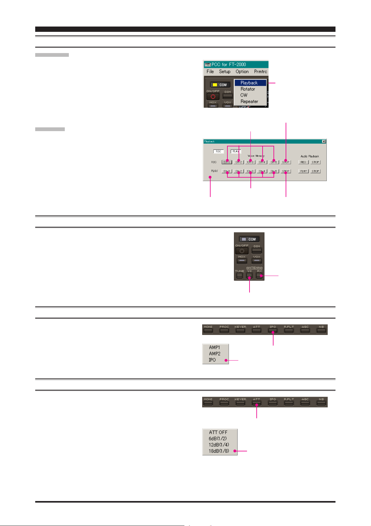
VOICE MEMORY FEATURE
RECORDING
1. Click the left mouse button on the “Playback” parameter in
the “Option” menu on the “PCC-2000” Personal Computer
Controller to open the “Playback” pop-up window.
2. Click the left mouse button on the desired Memory Channel
button (REC [Ch-1] ~ REC [Ch-5]) for the Voice Memory
feature to initiate recording.
3. Click the left mouse button on the [STOP] button for the
Voice Memory feature to stop recording.
PLAYBACK
1. Click the left mouse button on the “Playback” parameter in
the “Option” menu on the “PCC-2000” Personal Computer
Controller to open the “Playback” pop-up window.
2. Click the left mouse button on the desired Memory Channel
button (PLAY [Ch-1] ~ PLAY [Ch-5]) for the Voice Memory
feature to begin playback of the recorded audio.
3. Click the left mouse button on the [STOP] button for the
Voice Memory feature to stop the playback.
REC [Ch-x] button
PLAY [Ch-x] button
“Playback” window
“Playback” parameter
[
STOP] button
[
PLAY] button
ANTENNA SELECTION
Click the left mouse button on the [ANTENNA 1/2] button to
open the “ANT” pop-up window, then select the antenna on which
you wish to operate.
To use the RX ANT, repeatedly click the left mouse button on the
[
ANTENNA RX] button to turn the RX antenna on and off. When
the RX antenna is selected, the “RX” icon will appear in the display.
IPO (INTERCEPT POINT OPTIMIZATION
Click the left mouse button on the [IPO] button to open the “IPO”
pop-up window, then select the front-end system you wish to
use.
AMP1: low-distortion amplifier.
AMP2: 2-stage low-distortion amplifier.
IPO: bypasses the front end RF amplifier.
ATT (ATTENUATOR
Click the left mouse button on the [ATT] button to open the “ATT”
pop-up window, then select the attenuation level which you wish
to utilize.
[
ANTENNA 1/2] button
)
[
IPO] button
“IPO” window
)
[
ATT] button
[RX]
button
- 8 -
“ATT” window
Page 9

PCC-2000 REFERENCE BOOK
RF GAIN CONTROL
MAIN BAND (VFO-A
Click the left mouse button on the main [RF GAIN] knob (the
indication color of “RF GAIN” will turn yellow), then turn the
mouse scroll or press the left/right buttons to adjust the RF gain.
SUB BAND (VFO-B
Click the left mouse button on the sub [RF GAIN] knob (the
indication color of “RF GAIN” will turn yellow), then turn the
mouse scroll or press the left/right buttons to adjust the RF gain.
)
)
VRF (VARIABLE RF FRONT-END FILTER) OPERATION
1. Click the left mouse button on the [VRF] button to open the
“VRF” pop-up window, then select the configuration you wish
to use.
VRF OFF: Turns the VRF filter off.
VRF ON: Turns the VRF filter on.
DEFAULT: Moves the passband of the VRF filter to the cen-
ter of the current amateur band.
2. When you have set the [VRF] button to “VRF ON:”
Bring the mouse cursor to the [VRF] knob, then turn the
mouse scroll to move the passband of the VRF filter.
Press and hold in the left mouse button on the edge of the
[
VRF] knob, then rotate the mouse to move the passband
of the VRF filter while holding the left mouse button.
[
VRF] knob
Main [RF GAIN] knobSub [RF GAIN] knob
[
VRF] button
“VRF” window
ROOFING FILTER SELECTION
Click the left mouse button on the [R.FLT] button to open the
“Roofing Filter” pop-up window, then select the bandwidth you
wish to utilize.
CONTOUR FILTER / APF (AUDIO PEAK FILTER
1. Click the left mouse button on the [CONT] button to open
the “Contour/APF” pop-up window, then select the configuration you wish to use.
OFF: Turns the Contour filter/APF both off.
CONTOUR: Turns the Contour filter on. The Contour filter
characteristic will appear in the display
APF: Turns the APF (Audio Peak Filter) filter on.
The APF is activated only with a CW mode.
The “CONTOUR” indication on the display
will change to “APF”.
2. When the Contour filter is set to on, click the left mouse but-
ton on the edge of the [CONTOUR] knob (the indication
color of “CONTOUR” will turn yellow), then turn the mouse
scroll or press the left/right buttons to adjust the center frequency of the Contour filter (There is no adjustmet knob as-
sociated with the APF).
“R.FLT” window
[
CONT] button
[
R.FLT] button
)
PERATION
O
[
CONTOUR] knob
“Contour/APF” window
- 9 -
Page 10

PCC-2000 REFERENCE BOOK
IF SHIFT OPERATION
Click the left mouse button on the edge of the [SHIFT] knob (the
indication color of “SHIFT” will turn yellow), then turn the mouse
scroll or press the left/right buttons to move the filter passband.
WIDTH OPERATION
Click the left mouse button on the edge of the [WIDTH] knob
(the indication color of “WIDTH” will turn yellow), then turn
the mouse scroll or press the left/right buttons to adjust the filter
bandwidth.
NOTCH OPERATION
[
SHIFT] knob
[
WIDTH] knob
1. Click the left mouse button on the [NOTCH] button to turn
the Notch filter on and off. When the Notch filter is set to on,
the Notch characteristic will appear in the display.
2. Click the left mouse button on the edge of the [COARSE
knob (the indication color of “COARSE” will turn yellow),
then turn the mouse scroll or press the left/right buttons to
perform coarse adjustment of the center frequency of the IF
Notch filter.
3. Click the left mouse button on the edge of the [FINE] knob
(the indication color of “FINE” will turn yellow), then turn
the mouse scroll or press the left/right buttons to make fine
adjustments to the center frequency of the IF Notch filter.
AUTO NOTCH OPERATION
Click the left mouse button on the [DNF] button to turn the Auto
Notch filter on and off. When the Auto Notch filter is set to on,
the “DNF” icon will appear in the display.
NOISE REDUCTION OPERATION
]
[
NOTCH] button
NOTCH [FINE] knob
NOTCH [COARSE] knob
[
DNF] button
1. Click the left mouse button on the [DNR] button to turn the
Digital Noise Reduction system on and off. When the Digital
Noise Reduction system is set to on, the “DNR” icon will
appear in the display.
2. Click the left mouse button on the edge of the [DNR] knob
(the font color of “DNR” will change to yellow), then turn
the mouse scroll or press the left/right buttons to select the
setting that most effectively reduces the noise level.
- 10 -
[
DNR] button
Page 11

PCC-2000 REFERENCE BOOK
NAR (ONE-TOUCH NARROW IF FILTER SELECTION
MAIN BAND (VFO-A
1. Click the left mouse button on the [NAR] button to engage
the preset “Narrow” IF filter selection. When the narrow bandwidth is engaged, the “NAR” indication will appear in the
display.
2. Click the left mouse button on the [NAR] button again; the
bandwidth will revert to that set by the [WIDTH] knob.
SUB BAND (VFO-B
1. Click the left mouse button on the [B] button.
2. Within five seconds of clicking the [B] button (while the im-
bedded orange indicator is illuminated), click the left mouse
button on the [NAR] button to toggle the bandwidth between
“Wide” and “Narrow.” When the “Narrow” option is selected,
the “NAR” icon will appear in the display.
)
)
NOISE BLANKER OPERATION
MAIN BAND (VFO-A
1. Click the left mouse button on the [NB] button to open the
“NB” pop-up window, then select the configuration you wish
to use.
NB OFF: Turns the Noise Blanker off.
NB ON: Turns the Noise Blanker on (for short-duration
pulses).
NB-W ON: Turns the Noise Blanker on (for longer-duration
pulses).
2. When you have set the [NB] button to “NB ON” or “NB-W
ON,” click the left mouse button on the [NB] knob (the indication color of “NB” will turn yellow), then turn the mouse
scroll or press the left/right buttons to select the noise blanking level.
)
[NB]
[NB]
)
[B]
button
[
NAR] button
button
knob
[B]
button
SUB BAND (VFO-B
1. Click the left mouse button on the [B] button, then click the
left mouse button on the [NB] button to open the “NB” popup window; now select the configuration you wish to use.
NB OFF: Turns the Noise Blanker off.
NB ON: Turns the Noise Blanker on (for short-duration
NB-W ON: Turns the Noise Blanker on (for longer-duration
2. When you have set the [NB] button to “NB ON” or “NB-W
ON,” left-click on the [B] button followed by the [NB] knob
(the indication color of “NB” will turn yellow), then turn the
mouse scroll or press the left/right buttons to select the desired noise blanking level.
)
pulses).
pulses).
“NB” window
- 11 -
Page 12

PCC-2000 REFERENCE BOOK
AGC
SUB BAND (VFO-B
Click the left mouse button on the [AGC] button to open the
“AGC” pop-up window, then select the desired receiver-recovery time.
SUB BAND (VFO-B
Click the left mouse button on the [B] button, and then click the
left mouse button on the [AGC] button to open the “AGC” popup window; now select the desired receiver-recovery time.
)
)
LOCK FEATURE
[
[B]
button
“AGC” window
AGC] button
Click the left mouse button on the [LOCK] button to turn the
Main Tuning Dial knob Lock “on” and “off.” When the Main
Tuning Dial knob is set to be locked, the “LOCK” icon will appear in the display.
VOX OPERATION
1. Click the left mouse button on the [VOX] button to turn the
VOX circuit on and off. When the VOX circuit is set to on,
the inside of the button glows red.
2. Click the left mouse button on the [VOX] knob (the indica-
tion color of “VOX” will turn yellow), then turn the mouse
scroll or press the left/right buttons to adjust the VOX gain.
3. Click the left mouse button on the [DELAY] knob (the indi-
cation color of “DELAY” will turn yellow), then turn the
mouse scroll or press the left/right buttons to adjust the hang
time of the VOX circuit.
[
VOX] knob
[
LOCK] button
[
VOX] button
[
DELAY] knob
- 12 -
Page 13

PCC-2000 REFERENCE BOOK
USING THE SPEECH PROCESSOR
1. Click the left mouse button on the [PROC] button to open
the “PROCESSOR” pop-up window, then select the configuration you wish to use.
OFF: Turns the Speech Processor off.
MIC-EQ: Turns the Speech Processor on, with the Paramet-
ric Microphone Equalizer. You may adjust the characteristic of the Parametric Microphone Equalizer
by the “Prmtrc” menu. See page 15 for details.
Note: This configuration is only selected on the
FT-2000D (200 W version).
PROC: Turns the Speech Processor on.
2. Click the left mouse button on the [PROC] knob (the indica-
tion color of “PROC” will turn yellow), then turn the mouse
scroll or press the left/right buttons to select the Compression
level.
USING THE MONITOR
1. Click the left mouse button on the [MONI] button to turn the
Monitor circuit on and off. When the Monitor is set to on, the
“MONI” icon will appear in the display.
2. Click the left mouse button on the [MONI] knob (the indica-
tion color of “MONI” will turn yellow), then turn the mouse
scroll or press the left/right buttons to adjust the Monitor level.
[
PROC] button
[
MONI] button
[
PROC] knob
“PROCESSOR” window
[
MONI] knob
ANTENNA TUNER OPERATION
Click the left mouse button on the [TUNE] button to open the
“TUNER” pop-up window, then select the configuration you wish
to use.
TUNER OFF: Turns the Automatic Antenna Tuner off.
TUNER ON: Turns the Automatic Antenna Tuner on.
TUNING: Turns the Automatic Antenna Tuner on, and
begins the automatic tuning process.
[
TUNE] button
“TUNER” window
- 13 -
Page 14

PCC-2000 REFERENCE BOOK
REPEATER OPERATION
1. Click the left mouse button on the “Repeater” parameter in
the “Option” menu on the “PCC-2000” Personal Computer
Controller to open the “Repeater” pop-up window.
2. Click the left mouse button on the [ENC], [SQL], or [OFF
button to select the desired CTCSS mode.
3. Click the left mouse button on the “Freq” button to open the
“CTCSS Tone Frequency” pop-up window, and then select
the desired tone frequency.
4. Click the [OK] button to close the “CTCSS Tone Frequency”
pop-up window.
5. Click the left mouse button on the [S],
select the desired Repeater Shift Direction.
6. Click the left mouse button on the Close Button “ ” on the
“Repeater” pop-up window to save the new setting and close
the “Repeater” pop-up window.
[–]
, or [+] button to
]
“Repeater” window
[
ENC] button
[
OFF] button
[
Freq] button
[
SQL] button
“Repeater” parameter
Close button
[+]
button
[–]
button
[S]
button
“CTCSS Tone Frequency” window
[OK]
button
- 14 -
Page 15

PCC-2000 REFERENCE BOOK
PARAMETRIC MICROPHONE EQUALIZER ADJUSTMENT
1. Click the left mouse button on the “Prmtrc” menu on the
“PCC-2000” Personal Computer Controller to open the “Parametric” pop-up window, then select the configuration you wish
to use.
Prmtric: Adjust the characteristic of the Parametric Mi-
crophone Equalizer when the Speach Processor
is disabled.
P-Prmtric: Adjust the characteristic of the Parametric Mi-
crophone Equalizer when the Speach Processor
is enabled.
2. When click the left mouse button on the “Prmtrc” or “P-Prmtrc” menu, open the “Parametric Microphone Equalizer
Graph” window on the monitor.
3. Adjust the characteristic of the Parametric Microphone Equalizer using the each arrow switch. You may observe the
setting of the characteristic of the Parametric Microphone Equalizer on the monitor.
Red Curve: Appears the characteristic of the lower range for the parametric microphone equalizer.
Blue Curve: Appears the characteristic of the middle range for the parametric microphone equalizer.
Green Curve: Appears the characteristic of the high range for the parametric microphone equalizer.
Black Curve: Appears the characteristic of the overall range for the parametric microphone equalizer.
4. Click the left mouse button on the [APPLI] button on the “Parametric Microphone Equalizer Graph” window to save
the new setting and click the left mouse button on the [EXIT] button on the “Parametric Microphone Equalizer Graph”
window to close the “Parametric Microphone Equalizer Graph” window.
“Parametric” window
c
d
e
f
g
h
“Parametric Microphone Equalizer Graph” window
i
j
k
PRMTRC EQ1 (P-PRMTRC EQ1) FREQ
c
Click the left mouse button on the [Å]/[Æ] button to
selects the center frequency of the lower range for the
parametric microphone equalizer.
Available selections are 100 ~ 700 Hz (100 Hz/step)
or OFF.
- 15 -
PRMTRC EQ1 (P-PRMTRC EQ1) LEVEL
d
Click the left mouse button on the [Ç]/[È] button to
adjusts the equalizer gain of the low range of the parametric microphone equalizer.
Available selections are –20 dB ~ +10 dB.
PRMTRC EQ1 (P-PRMTRC EQ1) BWTH
e
Click the left mouse button on the [ÆÅ]/[ÅÆ] button to adjusts the Q-factor of the low range of the parametric microphone equalizer.
Available selections are 1 ~ 10.
Page 16

PCC-2000 REFERENCE BOOK
PARAMETRIC MICROPHONE EQUALIZER ADJUSTMENT
PRMTRC EQ2 (P-PRMTRC EQ2) FREQ
f
Click the left mouse button on the [Å]/[Æ] button to
selects the center frequency of the middle range for
the parametric microphone equalizer.
Available selections are 700 ~ 1500 Hz (100 Hz/step)
or OFF.
PRMTRC EQ2 (P-PRMTRC EQ2) LEVEL
g
Click the left mouse button on the [Ç]/[È] button to
adjusts the equalizer gain of the middle range of the
parametric microphone equalizer.
Available selections are –20 dB ~ +10 dB.
PRMTRC EQ2 (P-PRMTRC EQ2) BWTH
h
Click the left mouse button on the [ÆÅ]/[ÅÆ] button to adjusts the Q-factor of the middle range of the
parametric microphone equalizer.
Available selections are 1 ~ 10.
PRMTRC EQ3 (P-PRMTRC EQ3) FREQ
i
Click the left mouse button on the [Å]/[Æ] button to
selects the center frequency of the high range for the
parametric microphone equalizer.
Available selections are 1500 ~ 3200 Hz (100 Hz/step)
or OFF.
[
EXIT] Button
Click the left mouse button on this button to close the
“Repeater” pop-up window.
[
CANCEL] Button
Click the left mouse button on this button to save the
new setting.
[
APPLI] Button
Click the left mouse button on this button to save the
new setting.
[
FILE SAVE] Button
Click the left mouse button on this button to open the
“File Save” pop-up window and save the new setting
to your computer (pef file).
[
FILE LOAD] Button
Click the left mouse button this button to open the
“File Load” pop-up window and load the previously
stored setting.
PRMTRC EQ3 (P-PRMTRC EQ3) LEVEL
j
Click the left mouse button on the [Ç]/[È] button to
adjusts the equalizer gain of the high range of the parametric microphone equalizer.
Available selections are –20 dB ~ +10 dB.
PRMTRC EQ3 (P-PRMTRC EQ3) BWTH
k
Click the left mouse button on the [ÆÅ]/[ÅÆ] button to adjusts the Q-factor of the high range of the
parametric microphone equalizer.
Available selections are 1 ~ 10.
KEYER OPERATION
1. Click the left mouse button on the [KEYER] button to turn
the CW Keyer on and off. When the CW Keyer is set to on,
the “KEYER” icon will appear in the display.
2. Click the left mouse button on the [SPEED] knob (the indi-
cation color of “SPEED” will turn yellow), then turn the mouse
scroll or press the left/right buttons to set the desired keying
speed.
3. Click the left mouse button on the [PITCH] knob (the indica-
tion color of “PITCH” will turn yellow), then turn the mouse
scroll or press the left/right buttons to set the desired CW
tone pitch.
4. Click the left mouse button on the [BK-IN] button to turn the
CW Break-in circuit on and off. When the CW Break-in circuit is set to on, the “BK-IN” icon will appear in the display.
5. Click the left mouse button on the [DELAY] knob (the indi-
cation color of “DELAY” will turn yellow), then turn the
mouse scroll or press the left/right buttons to adjust the CW
delay time.
[
KEYER] button
[
BK-IN] button
[
SPEED] knob
[
PITCH] knob
[
DELAY] knob
- 16 -
Page 17

PCC-2000 REFERENCE BOOK
CONTEST MEMORY KEYER
TEXT MEMORY STORAGE
1. Click the left mouse button on the “CW” parameter in the
“Option” menu on the “PCC-2000” Personal Computer Controller to open the “CW” pop-up window.
2. Click the left mouse button on the desired Text Memory Chan-
nel (“Text Ch-1” ~ “Text Ch-5”), then enter the message from
the computer’s keyboard. Remember to add the “}” character
at the end to signify the termination of the message.
3. Click the left mouse button on the [CH-x WR] button to save
the message.
PLAYBACK
1. Click the left mouse button on the “Playback” parameter in
the “Option” menu on the “PCC-2000” Personal Computer
Controller to open the “Playback” pop-up window.
2. Click the left mouse button on the desired Memory Channel
button (Message Play [Ch-1] ~ Message Play [Ch-5] or Text
Play [Ch-1] ~ Text Play [Ch-5]) to begin playback of the
recorded audio.
“CW” parameter
“Message Play” button’s “Text Play” button’s
[
CH-x WR] buttonText Memory Channel
“CW” window
ROTATOR CONTROL
1. Click the left mouse button on the “Rotator” parameter in the
“Option” menu on the “PCC-2000” Personal Computer Controller to open the “Rotator” pop-up window.
2. Click the left mouse button on the [CCW] or [CW] button to
rotate the antenna.
3. Click the left mouse button on the [SLOW] or [FAST] but-
ton to adjust the rotation speed.
QMB MEMORY
“Rotator” window
[CW]
[
CCW] button
button
[
SLOW] button
“Rotator” parameter
[
FAST] button
Click the left mouse button on the [STO] button to write the
current main band (VFO-A) data to the QMB memory.
Click the left mouse button on the [RCL] button to recall the
QMB memory.
- 17 -
[
STO] button
[
RCL] button
Page 18

PCC-2000 REFERENCE BOOK
OPERATION OF MISCELLANEOUS KNOBS AND BUTTONS
[
METER] KNOB
Click the left mouse button on the [METER] knob, then turn the
mouse scroll or press the left/right buttons to select the function
of the meter during transmission.
[
MIC] K
Click the left mouse button on the [MIC] knob (the indication
color of “MIC” will turn yellow), then turn the mouse scroll or
press the left/right buttons to select the Microphone gain level.
[
RF PWR] KNOB
Click the left mouse button on the [RF PWR] knob (the indication color of “RF PWR” will turn yellow), then turn the mouse
scroll or press the left/right buttons to set the desired output power.
[
DIM] BUTTON
Click the left mouse button on the [DIM] button to toggle the
illumination level of the Meter/Display between “Hi” and “Low.”
[
MOX] BUTTON
Click the left mouse button on the [MOX] button to engage transmission. When the MOX circuit is set to on, the inside of the
button glows red.
NOB
[
MIC] knob
[
METER] knob
[
RF PWR] knob
[
DIM] button
[
MOX] button
[
SPOT] BUTTON
Click the left mouse button on the [SPOT] button to turn on the
CW receiver spotting tone.
[A]
BUTTON
When this button glows red, the following buttons are active on
the Main Band (VFO-A).
[MODE] Button
[BAND] Button
[NAR] Button
[AGC] Button
[NB] Button
[NB] Knob
[B]
BUTTON
Click the left mouse button on the [B] button to turn the button
orange for five seconds. When this button glows orange, the following buttons are active on the Sub Band (VFO-B).
[MODE] Button
[BAND] Button
[NAR] Button
[AGC] Button
[NB] Button
[NB] Knob
[
SPOT] button
[A]
button
[B]
button
- 18 -
Page 19

PCC-2000 REFERENCE BOOK
OPERATION OF MISCELLANEOUS KNOBS AND BUTTONS
[
SPLIT] BUTTON
Click the left mouse button on the [SPLIT] button to open the
“SPLIT” pop-up window, then select the configuration you wish
to use.
SPLIT: Toggle the Split Frequency operation on and
off. The VFO-A will be used for reception,
and VFO-B will be used for transmssion.
QUICK SPLIT: Activates the Quick Split feature.
(Sub (VFO-B) register will automatically
be set to a frequency 5 kHz higher than the
Main (VFO-A) register with same operating mode.)
[
TXW] BUTTON
Click the left mouse button on the [TXW] button to monitor the
transmit frequency when split frequency operation is engaged.
Release the mouse button to return to normal operation.
[
SPLIT] button
[
TXW] button
MAIN [RX] BUTTON
Click the left mouse button on the Main [RX] button to toggle
the Main Band (VFO-A) receiver on and off. When the Main
Band (VFO-A) receiver is set to on, the button glows green.
MAIN [TX] BUTTON
Click the left mouse button on the Main [TX] button to toggle
transmitter control between the “Main Band (VFO-A)” and “Sub
Band (VFO-B).” When the transmitter control is set to “Main
Band (VFO-A),” this button glows red.
SUB [RX] BUTTON
Click the left mouse button on the Sub [RX] button to toggle the
Sub Band (VFO-B) receiver on and off. When the Sub Band
(VFO-B) receiver is set to on, this button glows green.
SUB [TX] BUTTON
Click the left mouse button on the Sub [TX] button to toggle
transmitter control between the “Main Band (VFO-A)” and “Sub
Band (VFO-B).” When the transmitter control is set to “Sub Band
(VFO-B),” this button glows red.
Main [RX] button Main [TX] button
Sub [RX] button Sub [TX] button
- 19 -
Page 20

PCC-2000 REFERENCE BOOK
OPERATION OF MISCELLANEOUS KNOBS AND BUTTONS
[
FAST] BUTTON
Click the left mouse button on the [FAST] button to toggle the
tuning rate of the Main Tuning Dial knob between “Fast” and
“Slow.” When the tuning rate is set to “Fast,” the “FAST” icon
will appear in the display.
[
AXB] BUTTON
Click the left mouse button on the [AXB] button to transfer data
from the Main band (VFO-A) frequency (or a recalled memory
channel) to the Sub band (VFO-B).
X
[
A
B] BUTTON
W
Click the left mouse button on the [A
contents of the Main band (VFO-A) (or a recalled memory channel) and the Sub band (VFO-B).
[
V/M] BUTTON
Click the left mouse button on the [V/M] button to toggle the
Main band (VFO-A) receiver operation between the memory system and the VFO.
X
B] button to exchange the
W
[
FAST] button
[
X
A
B] button
X
[
A
B] button
W
[
V/M] button
[
MXA] button
[
AXM] button
[
MXA] BUTTON
Click the left mouse button on the [MXA] button to copy the
data from the currently-selected memory to the Main VFO (VFOA).
[
AXM] BUTTON
Click the left mouse button on the [AXM] button to copy the
current operating data from the Main band (VFO-A) into the
currently selected memory channel, overwriting any previous data
stored there.
MAIN (VFO-A) [BAND] BUTTON
Clicking the left mouse button on the Main (VFO-A) [BAND
button (the inside of the button will glow red) allows you to select the Main (VFO-A) operating band (Amateur bands) using
the [SUB VFO-B] knob.
MAIN (VFO-A) [MHZ] BUTTON
Clicking the left mouse button on the Main (VFO-A) [MHz] button (the inside of the button will glow red) allows you to turn the
Main (VFO-A) frequency down or up in 1 MHz increments, using the [SUB VFO-B] knob.
[
GRP] BUTTON
Clicking the left mouse button on the [GRP] button (the inside
of the button will glow red) allows you to select the memory
group using the [SUB VFO-B] knob.
]
Main [BAND] button
Main [MHz] button
[
GRP] button
[
MCH] button
[
MCH] BUTTON
Clicking the left mouse button on the [MCH] button (the inside
of the button will glow red) allows you to select the memory
channel using the [SUB VFO-B] knob.
- 20 -
Page 21

PCC-2000 REFERENCE BOOK
OPERATION OF MISCELLANEOUS KNOBS AND BUTTONS
SUB (VFO-B) [BAND] BUTTON
Clicking the left mouse button on the Sub (VFO-B) [BAND
button (the inside of the button will glow orange) allows you to
select the Sub (VFO-B) operating band (Amateur bands) using
the [SUB VFO-B] knob.
SUB (VFO-B) [MHZ] BUTTON
Clicking the left mouse button on the Sub (VFO-B) [MHz] button (the inside of the button will glow orange) allows you to turn
the Sub (VFO-B) frequency down or up in 1 MHz increments,
using the [SUB VFO-B] knob.
[
FAST] BUTTON
Clicking the left mouse button on the [FAST] button (the inside
of the button will glow orange) increases the tuning rate of the
[
SUB VFO-B] knob by a factor of 10.
[
A/B] BUTTON
Click the left mouse button on the [A/B] button to toggle the
actions of the [SUB VFO-B] button between the “Main band
(VFO-A)” and “Sub band (VFO-B).
]
Sub [BAND] button
Sub [MHz] button
[
FAST] button
[
A/B] button
[
DISPLAY] BUTTON
Click the left mouse button on the [DISPLAY] button to open
the “Display Page” pop-up window, and then select the display
page which you wish to engage for operation. This requires that
the optional DMU-2000 Data Management Unit be installed in
the transceiver.
WORLD CLOCK DISPLAY:
SPECTRUM SCOPE DISPLAY:
AF SCOPE/OSCILLOSCOPE DISPLAY:
LOG BOOK DISPLAY:
TEMPERATURE/SWR DISPLAY:
ROTATOR DISPLAY:
MEMORY CHANNEL DISPLAY:
[
DISPLAY] button
“Display Page” window
- 21 -
Page 22

PCC-2000 REFERENCE BOOK
MENU OPERATION
1. Click the left mouse button on the [MENU] button to open
the “MENU” window.
2. Turn the mouse scroll to select the Menu item you wish to
work on, then double click the left mouse button on the Menu
item to open the pop-up window.
3. Change the current setting of the selected Menu item, then
click the [OK] button to close the pop-up window.
4. Click the [OK] button to save the new setting and close the
“MENU” window.
[
MENU] button
“MENU LIST” window
“MENU LIST SETTING” window
[OK]
button
- 22 -
Page 23

PCC-2000 REFERENCE BOOK
COMMAND SEND
1. Click the left mouse button on the “Command Send” pa-
rameter in the “File” menu on the “PCC-2000” Personal
Computer Controller to open the “Command Send” pop-up
window.
2. Enter the CAT command you wish send to the FT-2000 with
the PC keyboard.
For example: Set the VFO-A frequency to 14.250000 MHz.
FA14250000;
Refer to a “FT-2000 CAT Operation Reference Book” for
the CAT command.
3. Click the [OK] button to send the CAT command to the trans-
ceiver and close the pop-up window.
“COMMAND SEND” parameter
“Command Send” window
[OK]
button
- 23 -
Page 24

PCC-2000 REFERENCE BOOK
FUNCTION KEY OPERATION
You can program and assign the CAT commands into your computer’s Function keys using the Vertex Standard KSE4PCC
Keyboard Shortcut Editor, then you may control the transceiver by pressing your computer’s Function keys while activating the “PCC-2000” Personal Computer Controller.
Each of the following 46 Function keys may be programmed with a CAT command sequence. There are a total of 52
commands to chose from:
[F2]
key ~ [F9
[
Shift] + [F1] key ~ [Shift] + [F9
[
Cntl] + [F1] key ~ [Cntl] + [F9
[
Alt] + [F1] key ~ [Alt] + [F3
[
Page Up
Following is an example of programming a CAT command shortcut into one of the Function keys:
1. Copy the “KSE4PCC.exe” file into the folder where you in-
stalled the “PCC-2000.exe” file.
2. Double click the left mouse button on “KSE4PCC.exe” to
open the “Keyboard Shortcut Editor” pop-up window.
3. Enter the CAT command you wish to assin to a specific Func-
tion key.
Example 1: Set the VFO-A frequency to 14.250000 MHz.
FA14250000;
Example 2: Set the VFO-A Operating Mode to “USB”.
MD02;
Example 3: Set the VFO-A frequecy to 14.250000 MHz,
FA14250000; MD02;
(Notice in Example 3 that you may assign more than one CAT
command to a single function key. Simply add a semi-colon
after each command, and end the command line with a semicolon).
Refer to the “FT-2000 CAT Operation Reference Book” for
the CAT command.
Note: You can not enter CAT commands into the following
function keys.
[F1]
key, [F10] key, [Shift] + [F10] key,
[
Cntl] + [F10] key, [Alt] + [F4] key, and [Alt] + [F6] key
4. You may append an Alpha-numeric “Tag” to a CAT Com-
mand for your reference (This is for reference only. The Alpha-numeric “Tag” is not displayed on the “PCC-2000” Personal Computer Controller).
To append a “Tag” to your CAT shortcut key, click the left
mouse button on the “Tag” or the “Both” parameter in the
“View” menu on the “Keyboard Shortcut Editor”. Your new
reference “Tag” appears in the “Tag” column on the “Keyboard Short-cut Editor”.
5. To close the “Keyboard Shortcut Editor” and save the CAT
commands, click “File” in the menu bar, and then click “Save”
in the drop-down list. In the Confirmation pop-up window,
click the [Yes] button to save the new setting.
] key, [
] key, [
Page Down
USB mode.
F11
] key, [
] key, [
] key, [
] key,
F12
] key, [
] key, [
Alt] + [F5
Shift] + [F11
Cntl] + [F11
] key, and [
Home
] key, [
] key, [
] key, [
Cntl] + [F12
Alt] + [F7
] key
End
Shift] + [F12
] key,
] key ~ [
Alt] + [F12
] key,
] key,
“View” menu
- 24 -
“Tag” column
“Tag” column
Page 25

PCC-2000 REFERENCE BOOK
NOTE
- 25 -
Page 26

PCC-2000 REFERENCE BOOK
Copyright 2009
VERTEX STANDARD CO., LTD.
All rights reserved
No portion of this manual
may be reproduced without
the permission of
VERTEX STANDARD CO., LTD.
 Loading...