

Page 1
DESKTOP DYNAMIC MICROPHONE
MD-200
A8X
Technical Supplement
©2001 VERTEX STANDARD CO., LTD. Printed in Japan.
Introduction
The Desktop Microphone is designed for base station op-
eration with the latest generation of Yaesu HF transceivers, includ-
ing those with VHF/UHF capability. Designed especially for ultra-
low distortion and the highest fidelity, the
technology “Variable Side Pressure Control” (VSPC), which allows
precise adjustment of the microphone’s audio response without re-
sorting to “active” equalization circuits that can introduce distortion
and/or degrade signal-to-noise ratio.
includes a new-
VERTEX STANDARD CO., LTD.
4-8-8 Nakameguro, Meguro-Ku, Tokyo 153-8644, Japan
VERTEX STANDARD
US Headquarters
10900 Walker Street, Cypress, CA 90630, U.S.A.
YAESU EUROPE B.V.
P.O. Box 75525, 1118 ZN Schiphol, The Netherlands
YAESU UK LTD.
Unit 12, Sun Valley Business Park, Winnall Close
Winchester, Hampshire, SO23 0LB, U.K.
VERTEX STANDARD HK LTD.
Unit 5, 20/F., Seaview Centre, 139-141 Hoi Bun Road,
Kwun Tong, Kowloon, Hong Kong
DYNAMIC MICROPHONE
MD-200
Servicing this equipment requires expertise in handling surface mount
chip components. Attempts by unqualified persons to service this
equipment may result in permanent damage not covered by war-
ranty.
While we believe the technical information in this manual is correct,
VERTEX STANDARD assumes no liability for damage that may oc-
cur as a result of typographical or other errors that may be present.
Your cooperation in pointing out any inconsistencies in the technical
information would be appreciated.
VERTEX STANDARD reserves the right to make changes in this trans-
ceiver and the alignment procedures, in the interest of technological
improvement, without notification of owners.
Specifications
Microphone Element Type: Dynamic
Frequency Range: 30 - 17000 Hz
Sensitivity: –62 dB (1 kHz, 0 dB = 1 V/1 pa)
Impedance: 600 Ohms
Dimensions (WHD): 4.7” x 11.4” x 4.9”
(120 x 290.5 x 124.5 mm)
Weight: Approx. 2.2 lb. (1 kg.)
Specifications are subject to change without notice or obligation.
1
EAA98X900
Page 2
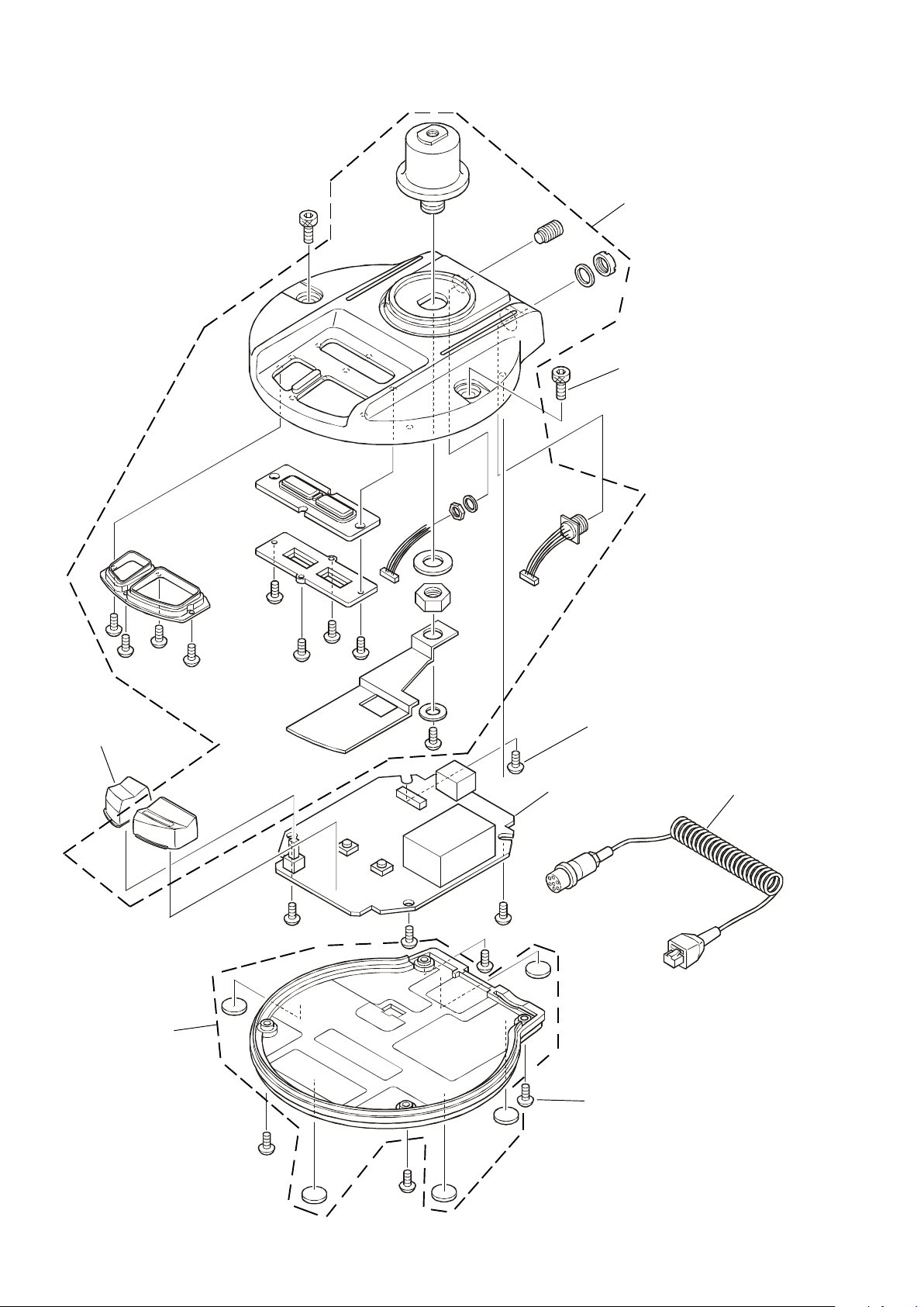
Exploded Views & Mechanical Parts Circuit Diagram
S8001978
STAND ASSY
S8001981 (X2 pcs)
HEX SOCKET HEAD BOLT
M6X8
S8001979
LOCK KNOB
S8001980
STAND COVER ASSY
U41306201 (X4 pcs)
TAPPING SCREW M3X6
S8101120
MAIN PCB
ASSY
S8001982 (X5 pcs)
TAPPING SCREW
M3X14
S8101121
CORD ASSY
Non-designated parts are available
only as part of a designated assembly.
2
Page 3
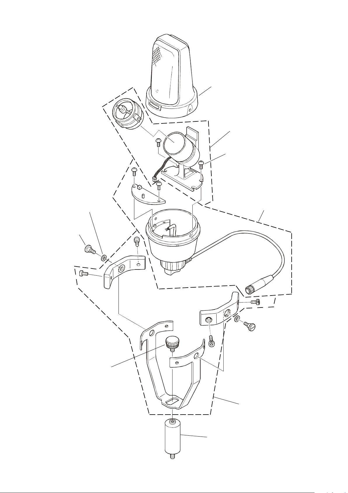
Exploded Views & Mechanical PartsParts Layout
S8001970
MIC HEAD
ASSY
S8001971
UNIT ASSY (w/o TAPPING SCREW)
U40308201 (X2 pcs)
TAPPING SCREW
3X8
S8001975 (X2 pcs)
RUBBER RING
S8001974 (X2 pcs)
SPECIAL SCREW
S8001976
KNOB SCREW
S8001972
BOTTOM CASE W/CABLE
ASSY
Non-designated parts are available
only as part of a designated assembly.
S8001973 (w/o KNOB SCREW)
ARM ASSY
S8001977
EXTENSION ADAPTER
3
Page 4

Circuit Diagram
BASE Unit Circuit Diagram
from JP2001
4
Page 5

Parts Layout
BASE Unit Parts Layout
a
MIC
GND
Side A
GND
MIC
a
JP1001
5
Page 6

BASE Unit Parts Layout
Side B
6
Page 7

LED Unit Circuit Diagram
from MIC
to J1001
LED Unit Parts Layout
Side A
Side B
7
Page 8

Parts List
REF. DESCRIPTION VALUE V/W TOL. MFR'S DESIG VXSTD P/N LOT. SIDE.
8
 Loading...