

Page 1
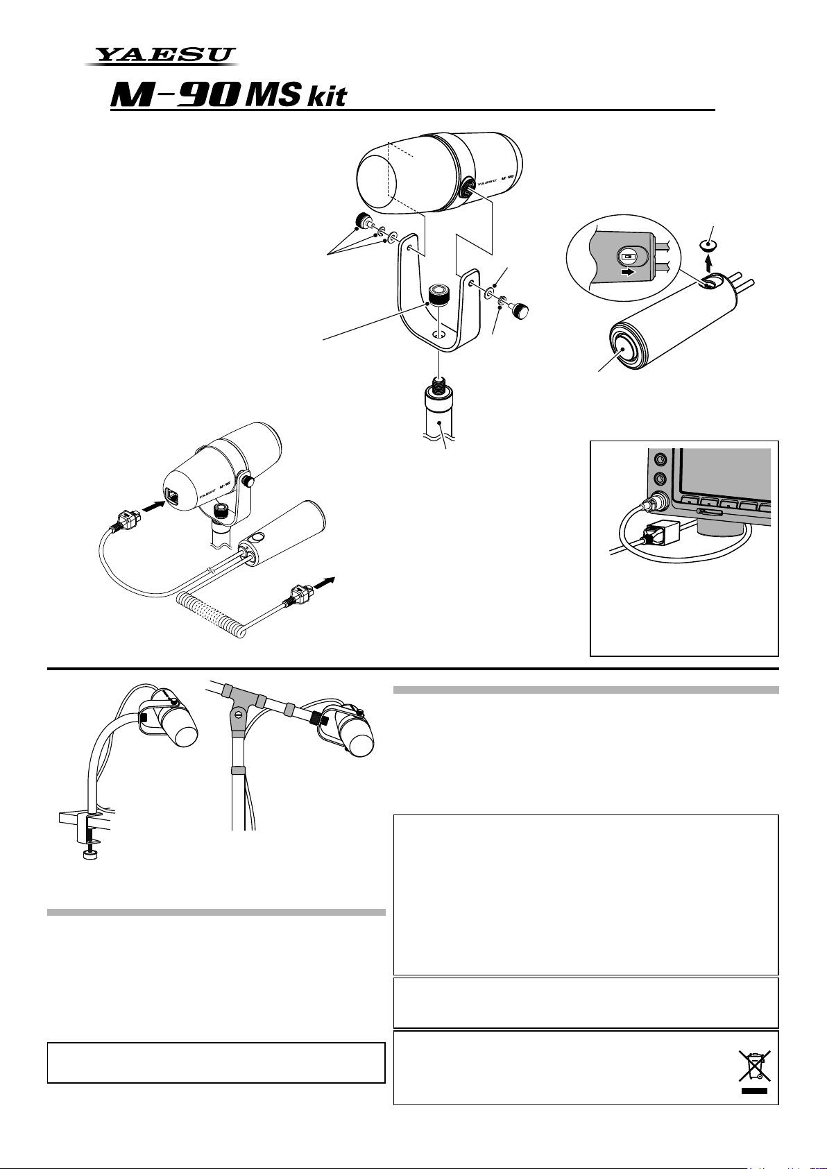
MICROPHONE STAND KIT
furnished with a round 8-pin microphone connector.
Connect the straight
cable connector.
Remove the cap.
W3/8 Nut
Use the supplied nut (W3/8 Nut) to attach the
yoke to a commercially available desk arm type,
or floor type microphone stand*.
Low-Cut switch
Turns the low-cut filter (cut-off frequency
Angle adjustment Screws
Attach the microphone body at the left and right
pivots with the supplied washers, lock washers,
and screws.
The angle of the microphone may be adjusted by
loosening the screws (turn them counterclockwise)
on the left and right side of the microphone yoke.
Place the microphone in the desired position and
then tighten the screws (turn them clockwise) to
secure the microphone.
*Microphone stand is not included.
This kit requires a commercially available microphone stand*.
*Microphone stand is not included.
340Hz, -6dB/octave) ON or OFF.
Move the switch in the direction of the
arrow to activate the low-cut filter.
washer
lock washer
PTT switch
When this switch is pressed, the transmit mode is
set and held.
When the switch is pressed again the transceiver
returns to receive mode.
This kit requires a Commercially available
microphone stand*.
Installation examples using
typical microphone stands*.
Using the M-90MS with Yaesu Transceivers
The M-90D operates with the below Transceivers.
FT-817/ND FT-818ND FT-857/D FT-891 FT-897/D
FT-450/D FT-900 FT-991/A FT-847 FT-920
FT-950 FT-1000MP FT-1000MP MARK-V FT-2000/D
FTDX1200 FTDX3000D FTDX5000 FTDX9000
FTDX101D FTDX101MP FTDX10
FT-747* FT-840* FT-850* FT-990* FT-1000*
* Requires Optional “Microphone Power Supply Kit”. as of June, 2021
Be sure to read the safety precautions printed in the Operating Manual of
the compatible transceiver to use this product safely.
YAESU MUSEN CO., LTD.
Tennozu Parkside Building
2-5-8 Higashi-Shinagawa, Shinagawa-ku, Tokyo 140-0002 Japan
Safety Precautions (Be Sure to Read)
Connect to the transceiver with the
8-pin modular microphone connector.
*An optional SCU-53 cable is required when
connecting the M-90MS to an HF transceiver
Specications
Supply Voltage: DC 5.0 V ±10 %
Current Consumption: 15 mA (TYP)
Microphone Type: Dynamic
Frequency Response: 30 - 17000 Hz
Sensitivity: -60 dB (1 kHz 0 dB=1V/Pa)
Microphone Impedance: 600 Ohms
Dimensions: Diameter: 2.45” (62mm), Length: 6.38” (162mm)
*Microphone head size only
Weight (approx):
This equipment has been tested and found to comply with the limits for a Class
B digital device, pursuant to Part 15 of the FCC Rules. These limits are designed
to provide reasonable protection against harmful interference in a residential
installation. This equipment generates, uses and can radiate radio frequency
energy and, if not installed and used in accordance with the instructions, may cause
harmful interference to radio communications. However, there is no guarantee that
interference will not occur in a particular installation.
If this equipment does cause harmful interference to radio or television reception,
which can be determined by turning the equipment o and on, the user is encouraged
to try to correct the interference by one or more of the following measures:
Reorient or relocate the receiving antenna.
Increase the separation between the equipment and receiver.
Connect the equipment into an outlet on a circuit dierent from that to which the
receiver is connected.
Consult the dealer or an experienced radio/TV technician for help.
This device complies with part 15 of the FCC Rules. Operation is subject to the
following two conditions: (1) This device may not cause harmful interference, and (2)
this device must accept any interference received, including interference that may
cause undesired operation.
Products with the symbol (crossed-out wheeled bin) cannot be disposed of
as household waste. Electronic and Electrical Equipment should be recycled
at a facility capable of handling these items and their waste by products.
Please contact a local equipment supplier representative or service center
for information about the waste collection system in your country.
Disposal of Electrical and Electronic Equipment
7.05 oz (200 g) w/ Bracket, w/o Handheld PTT Controller
Example using the
SCU-53 (optional)
As shown in the gure, route the
optional SCU-53 cable behind
the transceiver leg to avoid inter
fering with transceiver operation.
EBC63X750 (2106N-AS)
-
 Loading...