

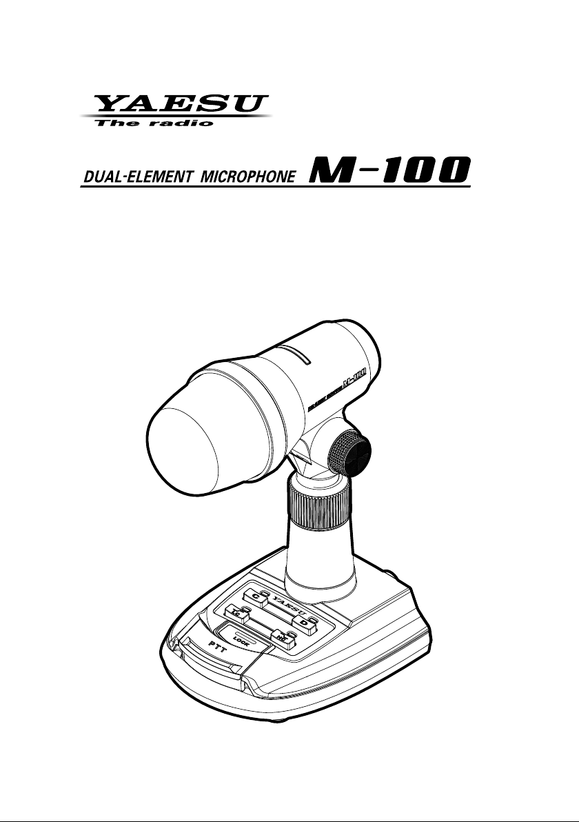
Page 1
Page 2

Contents
General Description ........................1
Safety Precautions ..........................2
Controls & Connections .................4
C key (Condenser Mic Element key
D key (Dynamic Mic Element key
LC (Low-Cut) key ..................................5
HC (High-Cut) key .................................5
LOCK key ..............................................5
PTT key .................................................5
).....4
) ........4
On Air Indicator .....................................5
MIC ........................................................6
Angle adjustment knobs ........................6
Height adjustment ring ..........................6
MIC Jack (8-pin) ....................................7
MIC Jack (modular) ...............................7
Fequency characteristics
of the microphone ...........................8
Specications ..................................8
Supplied Accessories
Treble boost cowling ........................................................................................... 1
Microphone Cable .............................................................................................. 1
Instruction Manual (this manual) ........................................................................ 1
About this manual
This manual contains symbols and conventions to call attention to important information.
Symbols Description
This icon indicates cautions and alerts the user should be aware of.
This icon indicates helpful notes, tips and information.
Using the M-100 with Yaesu Transceivers
The M-100 operates with the below Transceivers.
FT-450/D FT-900 FTDX1200
FT-817/ND FT-920 FT-2000/D
FT-847 FT-950 FTDX3000D
FT-857/D FT-991/A FTDX5000
FT-897/D FT-1000MP FTDX9000
FT-891 FT-1000MP MARK-V FTDX101D
FTDX101MP
FT-840* FT-990*
FT-850* FT-1000*
FT-747*
* Requires Optional "Power Supply Kit for M-100".
as of Oct, 2019
Page 3

General Description
Dual microphone conguration features
The M-100 features two built-in microphone elements, one dynamic and one condenser.
The unique output signals may be individually crafted and then blended to produce a single rich voice signal. The condenser microphone responds to a broad frequency range
including the distinctive crisp highs, while the dynamic microphone adds depth and
warmth, providing the emotional subtext desirable for a genial “ragchew”. By combining
the two different microphone elements in this manner, a favorable sound quality can be
created for any operating style.
Treble boost cowling produces a unique tonal texture
The simple clip-on cowling enhances the high-frequency response of both microphone
elements, and can minimize the aural interference from either side. The cowling serves
to concentrate the voice input with a peak at around 1 - 1.5 kHz, producing a unique tonal texture.
Air cylinder magnetic contactless PTT key
The PTT key with contactless triple air cylinder magnetic construction delivers smooth
ngertip-sensitive operation over an extended stroke distance.
The key has been designed with optimal balance between key weight and stroke to provide the perfect tactile response. Meanwhile, the contactless switch provides years of
fault-free operation with minimal mechanical degradation.
The PTT key features a built-in one click lock function.
Convenient High-Cut lter and Low-Cut lter key buttons are at your ngertips.
M-100 Operating Manual
1
Page 4
Safety Precautions
Note beforehand that the company shall not be liable for any damages suffered by the
customer or third parties in using this product, or for any failures and faults that occur
during the use or misuse of this product, unless otherwise provided for under the law.
Type and meaning of the symbols
This symbol indicates the possibility of death or serious injury
DANGER
WARNING
CAUTION
being inflicted on the user and the surrounding people when
these instructions are ignored and the product is mishandled.
This symbol indicates the possibility of death or serious injury
being inflicted on the user and the surrounding people when
these instructions are ignored and the product is mishandled.
This symbol indicates the possibility of physical impediments
occurring or impediments being inflicted on the user and the
surrounding people when these instructions are ignored and the
product is mishandled.
Type and meaning of symbols
Prohibited actions that must not be attempted, in order to use this radio safely.
For example, signies that disassembly is prohibited.
Precautions that must be adhered to in order to use this radio safely.
For example, signies that the power supply is to be disconnected.
DANGER
Do not use this product while driving or riding a motorbike. This may result in accidents.
Make sure to stop the car in a safe location rst before use if the device is going to be used by the driver.
WARNING
Do not dismantle or modify the device.
This may result in injury, electric shock and
equipment failure.
When smoke or strange odors are emitted from the radio, turn off the power and
dis-connect the power cord from the socket.
This may result in re, liquid leak, overheating, damage, ignition and equipment failure.
Please contact our company amateur customer support or the retail store where you
purchased the device.
Do not handle the power plug and connector etc. with wet hands. Also do not
plug and unplug the power plug with wet
hands.
This may result in injury, liquid leak, electric
shock and equipment failure.
2
Keep the power plug pins and the surrounding areas clean at all times.
This may result in re, liquid leak, overheating, breakage, ignition etc.
Do not install in places where the unit
risks getting wet (such as near a humidier).
Doing so may result in re, electric shock or
damage.
Do not place heavy objects on the power
supply cable or connection cable, forcibly
bend, twist or pull on the cables, or heat
or modify them.
Doing so may scratch or damage the cables,
resulting in re, electric shock or damage to
the equipment.
M-100 Operating Manual
Page 5

Safety Precautions
Do not pull on the cable section when
disconnecting the power supply cable or
connection cable.
Doing so could cause fire, electric shock or
damage to the equipment. Hold the plug or
the connector when disconnecting the cable.
CAUTION
Do not place the unit on an unstable place
or a place subject to much vibration.
The unit may fall or tip over, resulting in re,
injury or malfunction.
Do not place heavy objects on top of the
unit.
The unit may fall or tip over, resulting in injury.
Do not place objects containing water,
such as vases, cosmetics or cups, on top
of the unit.
The water may spill and get inside the unit,
resulting in re or malfunction.
Do not place the unit in humid or dusty
places.
Doing so could cause re or malfunction.
Do not wipe the case with thinner or benzene.
Use a soft, dry cloth to wipe dirt off the case.
Do not use the power supply cable or connection cable if it is damaged or if the connection of the power connector is loose.
Doing so could cause fire, electric shock or
damage to the equipment. Contact your dealer or our customer support.
Do not drop the unit or subject it to strong
shocks.
Doing so could cause injury or malfunction.
Disconnect the power supply cable and
all cables connecting the unit to the radio
before moving the microphone.
Do not place the unit in places exposed to
direct sunlight or near heating appliances.
Doing so could cause deformation, discoloration, etc.
Store in a place out of the reach of small
children.
Failure to do so could result in injury, etc.
Do not use products other than those
specied by Yaesu.
Doing so may result in malfunction.
Special Precautions in using the M-100
To reduce extraneous noise, place the microphone as far away as possible from
r
power supply equipment and power supply cables.
To avoid adverse effects of transmitted RF radio waves, install the microphone as far
r
away as possible from the transmitter antenna and antenna cable.
M-100 Operating Manual
3
Page 6

Controls & Connections
⑦
⑧
⑨
⑩
①
③
⑤
⑥
②
④
C key (Condenser Mic Element key
Switches to the condenser microphone ([C] LED lights up orange).
When the [C] and [D] keys are pressed, the audio output signals of the condenser and dynamic microphone elements are combined.
D key (Dynamic Mic Element key
Switches to the dynamic microphone ([D] LED lights up orange)
When the [C] and [D] keys are pressed, the audio output signals of the condenser and dynamic microphone elements are combined.
)
)
.
If neither the [C] key nor the [D] key is pressed, the microphone output is turned
off. The [C] and [D] LED’s blink simultaneously.
4
M-100 Operating Manual
Page 7

Controls & Connections
LC (Low-Cut) key
When this key is pressed, a low-cut lter (cut-off frequency 340 Hz, -6 dB/
octave) is activated ([LC] LED lights up blue).
HC (High-Cut) key
When this key is pressed, a high-cut lter (cut-off frequency 2 kHz, -6 dB/
octave) is activated ([HC] LED lights up blue).
When the [LC] and [HC] keys are pressed, both lters operate simultaneously.
While listening to the transmitted audio using the transceiver monitor function, adjust the microphone gain and the monitor level of the radio.
LOCK key
This is a one touch PTT key with a lock function.
When the LOCK key is pressed, the transmit mode is set and held, When
the key is pressed again the transceiver returns to receive mode again.
Operation of the PTT key is disabled when the LOCK key is operated.
r
The LOCK key indicator lights up red when the LOCK key is in operated.
r
PTT key
Press and hold down this key to transmit, and release it to receive.
The PTT key has a built in the magnetic sensor. Strong magnetic items, such
as a speaker or a magnet, may affect this PTT key, resulting in malfunctions.
On Air Indicator
This illuminates in red when in TX mode.
The indicator is off when in RX mode.
M-100 Operating Manual
5
Page 8

Controls & Connections
MIC
The unit includes a built-in dynamic microphone and a condenser microphone that are developed for communications equipment. The condenser
microphone provides crisp sound with transparent frequency characteristics
up to high frequencies. The dynamic microphone produces a thick, deep,
warm sound quality that is suited for informal chatting. It is also possible to
combine the audio output signals from the two microphone elements.
The included treble boost cowling may be
installed to block sounds from the sides
of the microphone, resulting in unique frequency characteristics as if the sound were
condensed with a peak response in the vicinity of 1 to 1.5 kHz. To install the cowling,
press it straight on from the front to cover
the microphone. To remove, slide it straight
off.
Angle adjustment knobs
The angle of the microphone may be adjusted by loosening (turn counterclockwise) the
knobs on the left and right side of the pivot
top. Place the microphone in the desired position and then tighten the knobs (turn them
clockwise) to secure the microphone.
Treble boost
cowling
Height adjustment ring
The height of the microphone can be precisely
adjusted. Turn the compression ring counterclockwise to loosen the top tube, and then raise
or lower the top section to the desired position.
Turn the compression ring clockwise to tighten it
and hold the microphone in place.
The stand can be extended a maximum of 6 cm.
6
M-100 Operating Manual
Page 9

Controls & Connections
NC
MIC
MIC
MIC GND
⑪ ⑫
MIC Jack (8-pin)
Use the supplied microphone cable to connect
the microphone to a transceiver that has a
“modular terminal”.
+5V
NC
MIC GND
PTT
MIC Jack (modular)
Use the supplied microphone cable to connect
the microphone to a transceiver that has an “8pin terminal”.
M-100 Operating Manual
NC
(
as viewed from rear side
NC
GND
PTT
(
as viewed from rear side
GND
NC
NC
+5V
)
)
7
Page 10

Frequency characteristics of the microphone
20.00
RELATIVE LEVEL [dB]
0
0
0
FREQUENCY [Hz]
RELATIVE LEVEL [dB]
RELATIVE LEVEL [dB]
15.00
Condenser Microphone
10.00
5.00
0.00
-5.00
-10.00
-15.00
-20.00
-25.00
-30.00
10 100 1000 10000 10000
20.00
15.00
Dynamic Microphone
10.00
5.00
0.00
-5.00
-10.00
-15.00
-20.00
-25.00
-30.00
10 100 1000 10000 10000
20.00
15.00
DUAL (Synthesis of condenser and dynamic microphones)
10.00
5.00
0.00
-5.00
-10.00
-15.00
-20.00
-25.00
-30.00
10 100 1000 10000 10000
Low-Cut Filter
FREQUENCY [Hz]
Low-Cut Filter
FREQUENCY [Hz]
Low-Cut Filter
Hi-Cut Filter
Hi-Cut Filter
Hi-Cut Filter
ø
These frequency characteristics may vary depending on the measurement environment.
Specifications
Supply Voltage: DC 5.0 V ±10 %
Current Consumption: 35 mA (TYP
Microphone Type: Dynamic microphone / Condenser microphone
Frequency Response: 30 - 17000 Hz
Sensitivity: -60 dB (1 kHz 0 dB=1V/1Pa
Microphone Impedance: 600 Ohms
Dimensions (WxHxD): 5.0” x 11.0” x 5.4” (126 x 280 x 137 mm)
*H: Maximum with microphone at
Weight (approx): 2.00 lbs (910 g) w/o cable
8
)
)
M-100 Operating Manual
Page 11

This equipment has been tested and found to comply with the limits for a Class B digital
device, pursuant to Part 15 of the FCC Rules. These limits are designed to provide reasonable
protection against harmful interference in a residential installation. This equipment generates,
uses and can radiate radio frequency energy and, if not installed and used in accordance with
the instructions, may cause harmful interference to radio communications. However, there is
no guarantee that interference will not occur in a particular installation.
If this equipment does cause harmful interference to radio or television reception, which can
be determined by turning the equipment off and on, the user is encouraged to try to correct
the interference by one or more of the following measures:
Reorient or relocate the receiving antenna.
Increase the separation between the equipment and receiver.
Connect the equipment into an outlet on a circuit different from that to which the receiver is
connected.
Consult the dealer or an experienced radio/TV technician for help.
This device complies with part 15 of the FCC Rules. Operation is subject to the following
two conditions: (1) This device may not cause harmful interference, and (2) this device must
accept any interference received, including interference that may cause undesired operation.
Disposal of Electrical and Electronic Equipment
Products with the symbol (crossed-out wheeled bin) cannot be disposed of as
household waste.
Electronic and Electrical Equipment should be recycled at a facility capable of handling these items and their waste by products.
Please contact a local equipment supplier representative or service center for information about the waste collection system in your country.
Page 12

Copyright 2017
YAESU MUSEN CO., LTD.
All rights reserved.
No portion of this manual may be
reproduced without the permission of
YAESU MUSEN CO., LTD.
YAESU MUSEN CO., LTD.
Tennozu Parkside Building
2-5-8 Higashi-Shinagawa, Shinagawa-ku, Tokyo 140-0002 Japan
YAESU USA
6125 Phyllis Drive, Cypress, CA 90630, U.S.A.
YAESU UK
Unit 12, Sun Valley Business Park, Winnall Close
Winchester, Hampshire, SO23 0LB, U.K.
1705G-DS-1
Printed in Japan
 Loading...