

Page 1
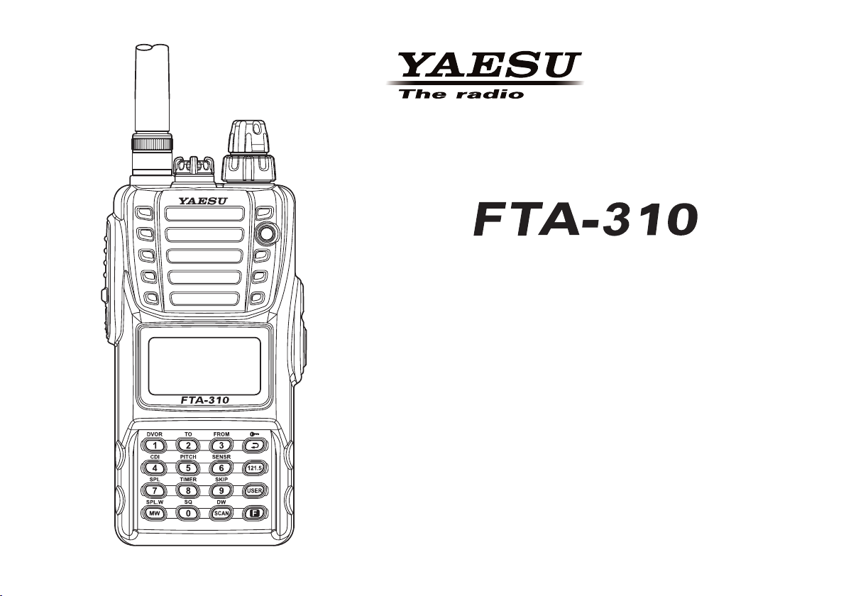
AIR BAND TRANSCEIVER
Operating Manual
Page 2

Contents
Important Notice! .......................................................... 1
Introduction ................................................................... 2
Accessories & Options ................................................ 3
Control & Connectors .................................................. 5
Top Panel ........................................................................... 5
Front Panel ......................................................................... 6
Side Panel .......................................................................... 7
Keypad ............................................................................... 8
LCD Display ...................................................................... 9
Before You Begin ........................................................ 10
Precautions ....................................................................... 10
Belt Clip Installation ........................................................ 10
Battery Installation and Removal .................................... 11
Battery Charging .............................................................. 12
Low Battery Indication .................................................... 13
Installing the FBA-25A Alkaline Battery Case ............... 13
Basic Operation .......................................................... 14
Preliminary Steps ............................................................. 14
Operation Quick Start ...................................................... 14
Squelch Adjustment ......................................................... 15
Accessing the 121.5 MHz Emergency Frequency ........... 16
Transmission .................................................................... 16
NOTICE
There are no user-serviceable points inside this
transceiver. All service jobs must be referred to
your Authorized Service Center.
Advanced Operation .................................................. 17
Tuning Methods ............................................................... 17
Reception of Weather Channel Broadcasts ...................... 18
Monitor Switch ................................................................ 19
ANL (Automatic Noise Limiter) Feature ........................ 19
Temperature/battery Voltage Display .............................. 20
LOCK Function ............................................................... 21
Beep On/Off ..................................................................... 21
Receive Battery Saver Setup ........................................... 22
Changing the Channel Steps ............................................ 23
Pitch Control .................................................................... 24
VOX Operation ................................................................ 25
PA Operation .................................................................... 26
Timer Operation ............................................................... 28
Memory Operation ...................................................... 30
Memory System Operation .............................................. 30
Memory Storage .............................................................. 30
Recalling the Memories ................................................... 31
Scanning Operation ................................................... 32
Dual Watch Operation ................................................ 34
Priority Dual Watch Operation .................................. 35
VOR Navigation .......................................................... 36
To Select the DVOR Mode .............................................. 37
Flying to a VOR Station .................................................. 38
Entering a Desired Course ............................................... 40
Position Cross-checking .................................................. 41
Split Operation ................................................................. 42
Programming the USER Key Assignment ................ 43
Field Programming Mode .......................................... 44
CPU Resetting ............................................................. 45
Menu (“Set”) Mode ..................................................... 46
Specications ............................................................. 54
Troubleshooting ......................................................... 56
Book Memory Channel List ....................................... 57
Page 3

Important notIce!
FCC RF Exposure Compliance Requirements for Occupational Use Only:
The
FTA-310
its for Occupational Use/Controlled Exposure Environment. In addition, it complies with the following Standards and
Guidelines:
FCC 96-326, Guidelines for Evaluating the Environmental Effects of Radio-Frequency Radiation.
FCC OET Bulletin 65 Edition 97-01 (1997) Supplement C, Evaluating Compliance with FCC Guidelines for Hu-
man Exposure to Radio Frequency Electromagnetic Fields.
ANSI/IEEE C95.1-1992, IEEE Standard for Safety Levels with Respect to Human Exposure to Radio Frequency
Electromagnetic Fields, 3 kHz to 300 GHz.
ANSI/IEEE C95.3-1992, IEEE Recommended Practice for the Measurement of Potentially Hazardous Electromag-
netic Fields - RF and Microwave.
This radio is NOT approved for use by the general population in an uncontrolled environment. This radio is
restricted to occupational use, work related operations only where the radio operator must have the knowledge to control its RF exposure conditions.
When transmitting, hold the radio in a vertical position with its microphone 1 to 2 inches (2.5 to 5 cm) away
from your mouth and keep the antenna at least 1 inch (2.5 cm) away from your head and body.
The radio must be used with a maximum operating duty cycle not exceeding 50%, in typical Push-to-Talk
congurations. DO NOT transmit for more than 50% of total radio use time (50% duty cycle). Transmitting
more than 50% of the time can cause FCC RF exposure compliance requirements to be exceeded.
The radio is transmitting when the red LED on the upper right corner of the front panel of the radio is illu-
minated. You can cause the radio to transmit by pressing the P-T-T button.
Always use Yaesu authorized accessories.
has been tested and complies with the Federal Communications Commission (FCC) RF exposure lim-
FTA-310 OperATing MAnuAl
1
Page 4
FTA-310 OperATing MAnuAl
IntroductIon
The YAESU
ceive) capability on the International Aircraft Communication Band (“COM” band: 118 ~ 136.975 MHz), and it additionally provides VOR and CDI navigation features on the “NAV” band (108 ~ 117.975 MHz).
The
FTA-310
8.33 kHz synthesizer steps for the receiving of the new narrow-band channel plan. The
perature and Supply Voltage displays with our exclusive Omni-GlowTM display back-lighting for minimal degradation
of your night vision, NOAA weather band monitoring, 8-character Alpha/Numeric Display, 150 Memory Channels, and
up to 100 “Book Memory” Channels. The channel congurations are can be easily reprogrammed in minutes using the
optional PC Programming Kit and your PC.
We recommend that you read this manual in its entirety, so as to understand the many features of the
pletely. Keep this manual handy, so you may use it for reference.
NOTE: The
FTA-310
boasts 0.8 Watt of clean audio output from its 1.4” (36-mm) diameter loudspeaker, and it also provides
FTA-310
tended to be a substitute for accurate (primary) VOR/CDI or landing service equipment.
is a compact, stylish, solid hand-held transceiver providing communication (transmit and re-
FTA-310
’s VOR and CDI Navigation features are supplemental aids to navigation only, and are not in-
includes both Tem-
FTA-310
com-
Congratulations!
You now have at your ngertips a valuable communications tool, a YAESU two-way radio! Rugged, reliable and
easy to use, your YAESU radio will keep you in constant touch with your friends and colleagues for years to come,
with negligible maintenance or down-time.
Please take a few minutes to read this manual carefully. The information presented here will allow you to derive
maximum performance from your radio, in case questions arise later on.
We’re glad you joined the YAESU team. YAESU products cover the entire spectrum of radio communications applications, and our worldwide support network is here to serve you. Let us help you get your message across.
2
Page 5

FTA-310 OperATing MAnuAl
accessorIes & optIons
Supplied Accessories
Ni-MH Battery Pack (7.2V)
Overnight Charger
Charger Cradle
12 V DC Charging Cradle
Helical Antenna
Quick Draw Belt Clip
Headset Cable
Alkaline Battery Case
Operating Manual
Warranty Card
“B” suffix is for use with 100-240 VAC, Type-A
plug or “C” suffix is for use with 100-240 VAC,
Type-C plug.
FNB-83
PA-48B/C
CD-28
CD-59
YHA-73
CLIP-14
CT-96
FBA-25A
Available Options
B4B
MH-44
E-DC-5B
E-DC-6
VAC-370
PC Programming Kit
Availability of accessories may vary. Some accessories
are supplied as standard per local requirements, while
others may be unavailable in some regions. Consult
your YAESU Dealer for details regarding these and any
newly-available options.
Connection of any non-YAESU-approved accessory,
should it cause damage, may void the Limited Warranty
on this apparatus.
Speaker Microphone
DC Cable w/Noise Filter
DC Cable; plug and wire only
Desktop Rapid Charger
3
Page 6
FTA-310 OperATing MAnuAl
accessorIes & optIons
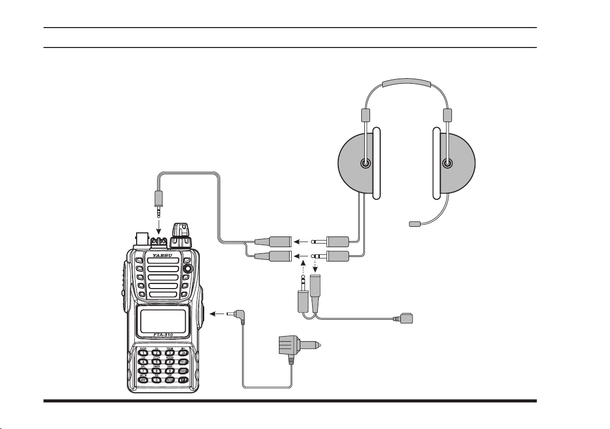
CT-96
Headset Cable
Headset
(not supplied)
PTT Switch
An e x t e r n a l PT T sw i t ch is
required for use with an aviation headset.
E-DC-5B
DC Cable w/Noise Filter (Option)
(not supplied)
4
Page 7
FTA-310 OperATing MAnuAl
controls & connectors (top panel
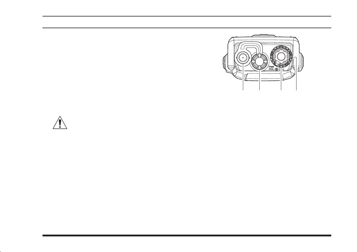
Antenna Jack
This BNC connector accepts the supplied flexible
antenna, or another antenna designed to provide 50
impedance on the Aircraft Communication Band.
)
MIC/EAR
You may connect the supplied
or the (optional)
to this jack. To use this jack, you must rst remove
the plastic cap by rotating it counter-clockwise, then
lifting it away from the transceiver body.
over the MIC/EAR jack is removed.
Jack
Headset Cable
CT-96
Speaker/Microphone
MH-44
Do not allow the
merged in water while the plastic cover
B4B
FTA-310
to become sub-
POWER/VOLUME
Turn this (inner) control clockwise to turn the radio
on and to increase the volume. Counterclockwise
rotation into the click-stop will turn the radio off.
Pressing this knob downward momentarily selects
the tuning methods among the VFO (Variable Frequency Oscillator), MR (Memory Recall), BOOK
(Pre-Programmed Memories), and WX (Weather
Channel Memories) modes.
Note: The WX mode is available in the USA ver-
sion only.
DIAL
This (outer) 20-position detented rotary switch tunes
the operating frequency or selects the memory channels.
Selector (Outer) Knob
(Inner) Knob
5
Page 8
FTA-310 OperATing MAnuAl
controls & connectors (Front panel
)
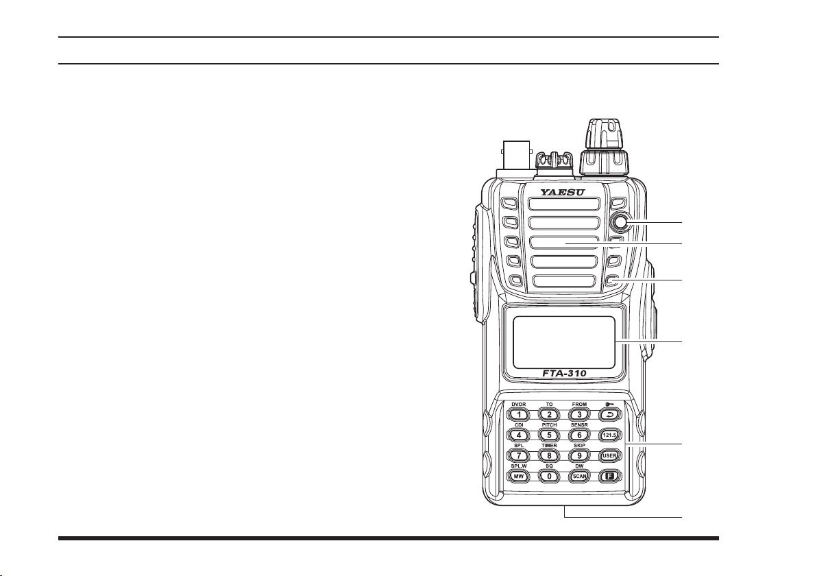
BUSY/TX
This lamp glows green when a signal is being re-
ceived, and red when transmitting.
Loudspeaker
The internal speaker is located in this position.
Microphone
Speak across this opening in a normal voice level,
while pressing the
LCD (Liquid Crystal Display)
The display shows selected operating conditions, as
indicated on the next page.
Keypad
The keypad is used for most radio command opera-
tions. Several keys have triple functions.
The primary functio ns are activated by si mply
pressing the key momentarily.
The secondary functions are activated by pressing
the key followed by
The third functions are activated by pressing and
holding in the key for 2 seconds.
These functions are described in detail on page 8.
Indicator Lamp
switch, to transmit.
PTT
[F]
key.
Battery Pack Latch
Open this latch for battery removal.
6
Page 9
FTA-310 OperATing MAnuAl
controls & connectors (sIde panel
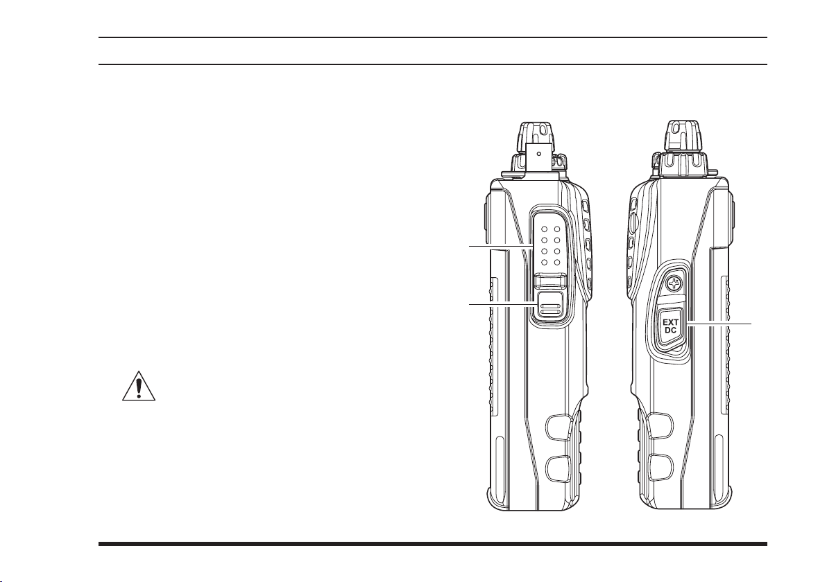
(Push To Talk) Switch
PTT
Press this button to transmit when you are operating
in the COM band. Release this button to return to
the “Receive” mode. See page 16 for details.
)
MONITOR
This button may be pressed to “open” the squelch
manually, allowing you to listen for very weak
signals. Press and hold this button for 2 seconds
to “open” the squelch continuously. Press this button again to resume normal (quiet) monitoring. See
page 15 for details.
EXT DC
When an external 12-Volt DC power source is avail-
able, you may connect the (optional)
ternal DC Cable here.
1) Do not allow the
submerged in water while the rubber cover
is removed.
2) Do not connect any wire to this jack if that wire
is connected directly to a 28-Volt DC source. Connecting the
exceeds 15.0 Volts DC will result in damage to the
unit, and this type of damage is not covered by the
Limited warranty on this product.
Switch
Jack
FTA-310
E-DC-5B
FTA-310
directly to a source which
to become
Ex-
7
Page 10
FTA-310 OperATing MAnuAl
controls & connectors (Keypad
)
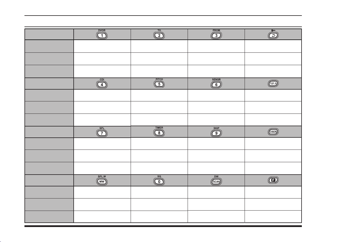
Primary Function
(
Press Key
Secondary Function
(
Press [F] + key
Third Function
(
Press and Hold key
Primary Function
(
Press Key
Secondary Function
(
Press [F] + key
Third Function
(
Press and Hold key
Primary Function
(
Press Key
Secondary Function
(
Press [F] + key
Third Function
(
Press and Hold key
Primary Function
(
Press Key
Secondary Function
(
Press [F] + key
Third Function
(
Press and Hold key
)
)
)
)
8
Frequency Entry Digit 1
)
)
)
)
Activates DVOR mode.
)
Frequency Entry Digit 4
Activates Deviation
Indicator mode.
)
Frequency Entry Digit 7
Activates Split (Duplex)
)
Split-Memory
“Write” Command.
Memory “Write”
)
None
None
mode.
None
None
Command.
Frequency Entry Digit 2
Activates “TO” VOR
mode.
None
Frequency Entry Digit 5
Activates Pitch Control
feature.
None
Frequency Entry Digit 8
Activates the Stop Watch
Timer.
None
Frequency Entry Digit 0
Adjusts the Squelch
threshold level.
None
Frequency Entry Digit 3
Activates “FROM” VOR
mode.
None
Frequency Entry Digit 6
Displays the Battery Voltage and Current
Temperature inside the transceiver’s case.
None
Frequency Entry Digit 9
Allows Skipping of
Channel during Scan.
None
Swiches the VFO mode
“A” and “B.”
Activates the Dual Watch
feature.
Activates Scanning.
Select Memory Display
Activates the Key Lockout
Selects DVOR Display
Selects Emergency
Channel (121.5 MHz).
Activates the Automatic Noise
Limiter during AM reception.
Activates the Public
Address feature.
Activates “Secondary” key
Cancel the “Secondary”
key mode of the [F] key.
Type.
feature.
Type
None
None
None
mode.
None
Page 11
FTA-310 OperATing MAnuAl
controls & connectors (lcd dIsplay
)
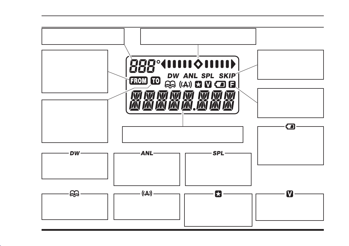
This f iel d displays the cour se
heading in degrees. See page 37.
This icon is used during
V O R n a v i g a t i o n , t o
indicate that the displayed
information is based on
a course from the VOR
station. See page 37.
This icon is used during
V O R n a v i g a t i o n , t o
indicate that the displayed
information is based on
a co u rs e to th e VO R
station. See page 37.
Th is indic ator c onfi rms
t h a t “D u a l Wa t c h ” i s
active. See page 34.
This icon indicates that
the “Book” Memory Bank
is in use. See page 17.
These digits provide frequency or alpha-numeric
information about the channel you are using.
Th is indic ator c onfi rms
that “Au t o ma ti c No is e
Limiter” is active. See
page 19.
This icon indicates that
the “Weather Alert” feature
is active. See page 52.
This is the Course Deviation Indicator, used
during VOR Navigation. See page 38.
This indicator conrms that
the “Split” (Duplex) mode
is activeted during VOR
operation. See page 42.
This icon indicates that the
channel step is selected to
“8.33 kHz” in the NAV and
COM band. See page 23.
Th is indic ator c onfi rms
that this channel will be
skipped during scan. See
page 33.
Th is indic ator c onfi rms
t h a t S e c o n d a ry Ke y
Funct ion is active. See
page 8.
Th i s ic on is th e “L ow
Battery” indicator, which
blinks when the battery
voltage becomes too low
for proper operation.
Thi s i n d i c a t o r confirms
t h a t “V OX ” sy st em is
active. See page 25.
9
Page 12

FTA-310 OperATing MAnuAl
BeFore you BegIn
Precautions
The
FTA-310
tion on channels used for critical aviation safety
communications. Therefore, it is important that this
radio be kept away from children or other unauthorized users at all times.
When making DC connections via the the optional
E-DC-5B/E-DC-6
to observe the proper voltage level and polarity
guidelines. Do not connect this radio directly to any
24 ~ 28 Volt DC source, nor to AC power of any
kind. Connecting the
which exceeds 15.0 Volts DC will result in damage
to the unit. The Limited Warranty for this product
does not cover damage caused by the application of
improper voltage.
Do not dispose of the Ni-MH Battery Pack in a re.
Do not carry a Ni-MH Battery Pack in your pocket,
where keys or coins could short the terminals. This
could create a serious re/burn danger, and possibly
cause damage to the Ni-MH pack.
Although the
ible (3 ft., 30 min.), its enclosure is not designed to
guarantee protection from ingress of water under
extreme pressure. Do not allow the radio to become
submerged in deep water, and do not subject it to
water spray under pressure.
is capable of two-way communica-
DC cable, be absolutely certain
directly to a source
FTA-310
FTA-310
is designed to be Submers-
Belt Clip Installation
Connect the hanger to the rear of the
the notch pointing directly up, using the supplied
screw (Fig 1). Use only the screw included with the
clip to mount the clip to the back of the
Clip the Quick-Draw Belt Clip onto your belt (Fig 2).
To install the
Clip, align the hanger with the Quick-Draw Belt
Clip, and slide the
is heard (Fig 3).
To remove the
Clip, rotate the
FTA-310
FTA-310
FTA-310
FTA-310
out from the Quick-Draw Belt Clip (Fig 4).
into the Quick-Draw Belt
FTA-310
into its slot until a click
from the Quick-Draw Belt
180 degrees, then slide the
FTA-310
FTA-310
, with
.
10
Page 13

FTA-310 OperATing MAnuAl
Fig 1
BeFore you BegIn
Battery Installation and Removal
To install the battery, insert the battery pack into the
Fig 2
To remove the battery, turn the radio off and remove
the Ni-MH pack could occur if a cell or cells become
accidentally short-circuited.
battery compartment on the back of the radio, then
close the Battery Pack Latch until it locks in place
with a “Click.”
any protective cases. Open the Battery Pack Latch
on the bottom of the radio, then lift the battery upward and out from the radio.
Do not attempt to open any of the rechargeable
Ni-MH packs, as personal injury or damage to
Fig 4Fig 3
11
Page 14
FTA-310 OperATing MAnuAl
BeFore you BegIn
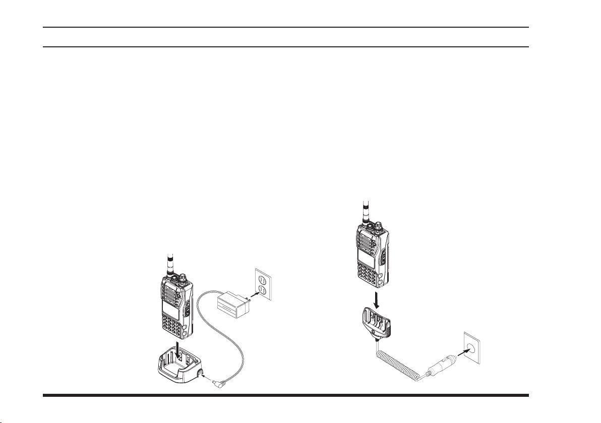
Battery Charging
It is necessary to charge the Ni-MH battery fully before
its rst use. Follow these procedures:
Install the supplied
onto the transceiver. Ensure that the transceiver is
switched off.
Use for PA-48/CD-28
1. Insert the cable plug into the jack located on the
right side of the
the
PA-48
2. Insert the transceiver and battery pack into the
; the antenna jack should be at the left side when
28
viewing the charger from the front.
3. If the transceiver and battery pack are inserted
co r re c tl y, the RE D
indicator on the
will glow. A fully-
28
discharged pack will
be charged completely
in 12 hours.
Battery Charger into the AC line outlet.
FNB-83
CD-28
CD-
Ni-MH battery pack
Charging Cradle then plug
CD-
PA-48
Use for CD-59
1. Insert the cigarette lighter plug into the cigarette
lighter socket (DC 11 V ~ 16 V).
2. Insert the transceiver and battery pack into the
; the antenna jack should be at the left side when
59
viewing the charger from the front.
3. If the transceiver and battery pack are inserted correctly, the RED indicator on the
fully-discharged pack will be charged completely in
15 hours.
CD-59
CD-59
will glow. A
CD-
12
CD-28
DC 11 V ~ 16 V
Page 15
FTA-310 OperATing MAnuAl
BeFore you BegIn
Important Notes:
The
for operation (reception or transmission).
Do not leave the charger connected to the trans-
ceiver for continuous periods in excess of 24 hours.
Long term overcharging can degrade the Ni-MH
battery pack and signicantly shorten its useful life.
If using a charger other than the
CD-59
FNB-83
vided with the charger/battery. Contact your Dealer
if you have any doubts about the appropriateness of
the particular charger or battery pack you intend to
use.
is not designed to power the transceiver
PA-48
PA-48/CD-28
, or if using a battery pack other than the
, follow the appropriate instructions pro-
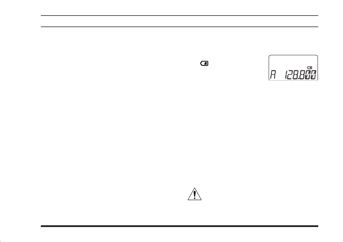
Low Battery Indication
As your battery discharges during use, the voltage
will gradually become lower. When the battery voltag e r e a c h es 6.0 Vol t s , the
” icon will blink on the
“
LCD display, indicating that
the battery pack must be re-
,
charged before further use.
Avoid recharging Ni-MH batteries before the “Low
Battery” indicator is observed, as this can degrade
the charge capacity of your Ni-MH battery pack.
YAESU recommends that you carry an extra, fullycharged pack with you so you will not lose communications capability due to a depleted Ni-MH battery.
Installing the FBA-25A Alkaline Battery Case
The
supplied
of the
When installing batteries, insert the (–) end first, then
press in the (+) end so the battery snaps into place. Always replace all six batteries at the same time, paying
attention to the polarity indicated inside the case.
thermal and over-current protection circuits (provided
in the “FNB” series of Ni-MH Battery Packs) required
when utilizing Ni-Cd and Ni-MH cells.
FBA-25A
FTA-310
The FBA-25A must not be used with rechargeable cells. The FBA-25A does not contain the
using six “AA” size Alkaline batteries.
Battery Case allows operation
13
Page 16
FTA-310 OperATing MAnuAl
BasIc operatIon
Preliminary Steps
Install a charged battery pack onto the transceiver,
as described previously.
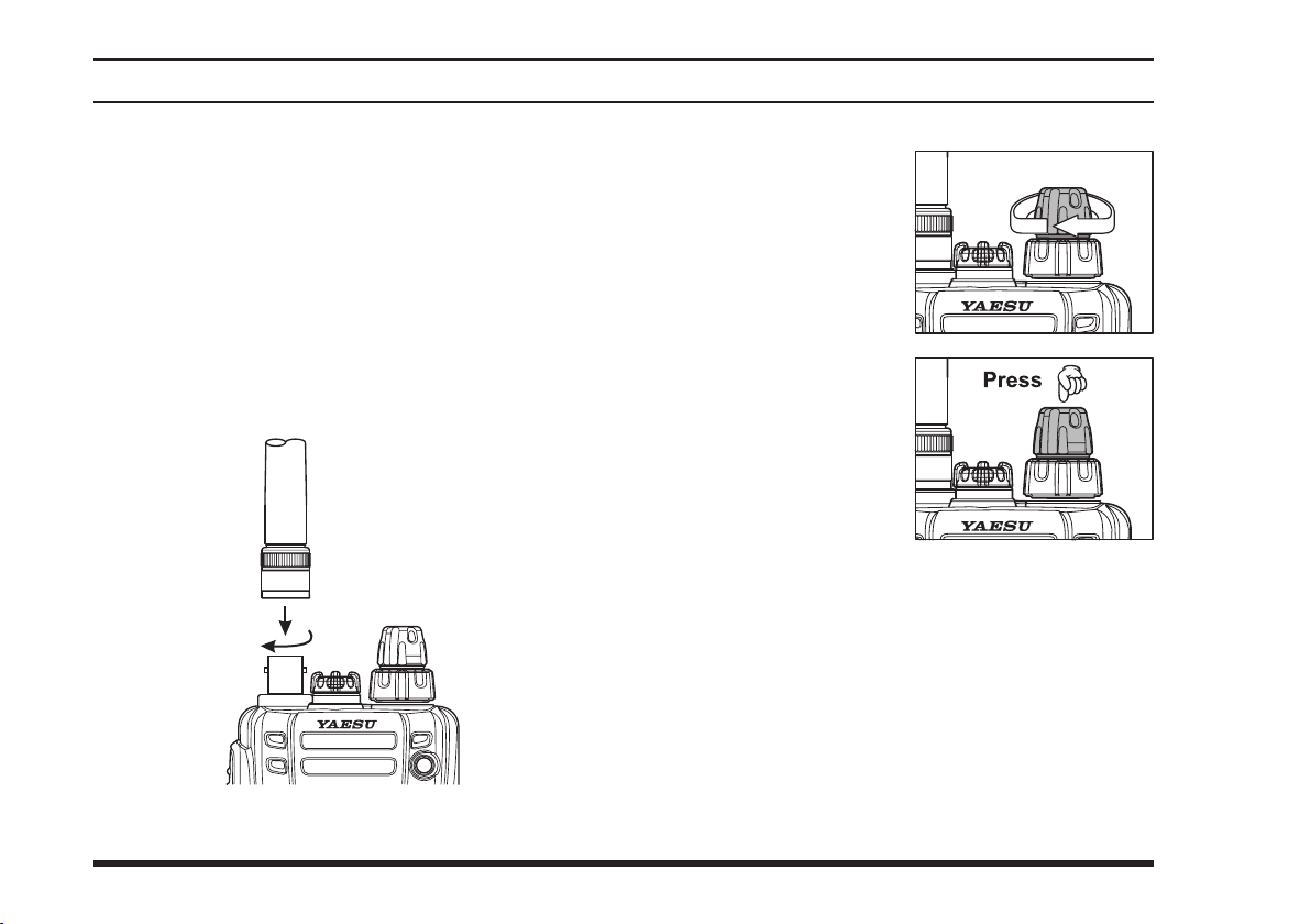
To attach the supplied antenna to the
grasp the base of the antenna firmly, and exert a
moderate “pinching” pressure on the base as you
press the antenna onto the radio’s antenna connector. While exerting this pressure, rotate the antenna
clockwise 1/4 turnto lock the antenna in place.
FTA-310
Operation Quick Start
To turn the radio on,
rotate the (inner)
,
A channel frequency
Directly entering frequencies from the keypad is the
For example, to set 134.35 MHz,
press
To set 118.275 MHz, you do not need to press the
knob out of the
UME
click-stop.
should appear on the display. If not, press downward (momentarily) on
th e
VO LU ME
(repeatedly, if necessary)
so that “
on the display, followed by a channel frequency.
easiest method if you know the frequency on which
you wish to operate. Just enter the ve digits of the
frequency to move to that frequency.
nal “5” in the frequency:
[1]
[1]
[1]
-
VFO
VOL-
kn ob
” appears
-
[3]
[8]
[4]
[2]
[3]
[7]
.
[5]
.
14
Page 17
FTA-310 OperATing MAnuAl
BasIc operatIon
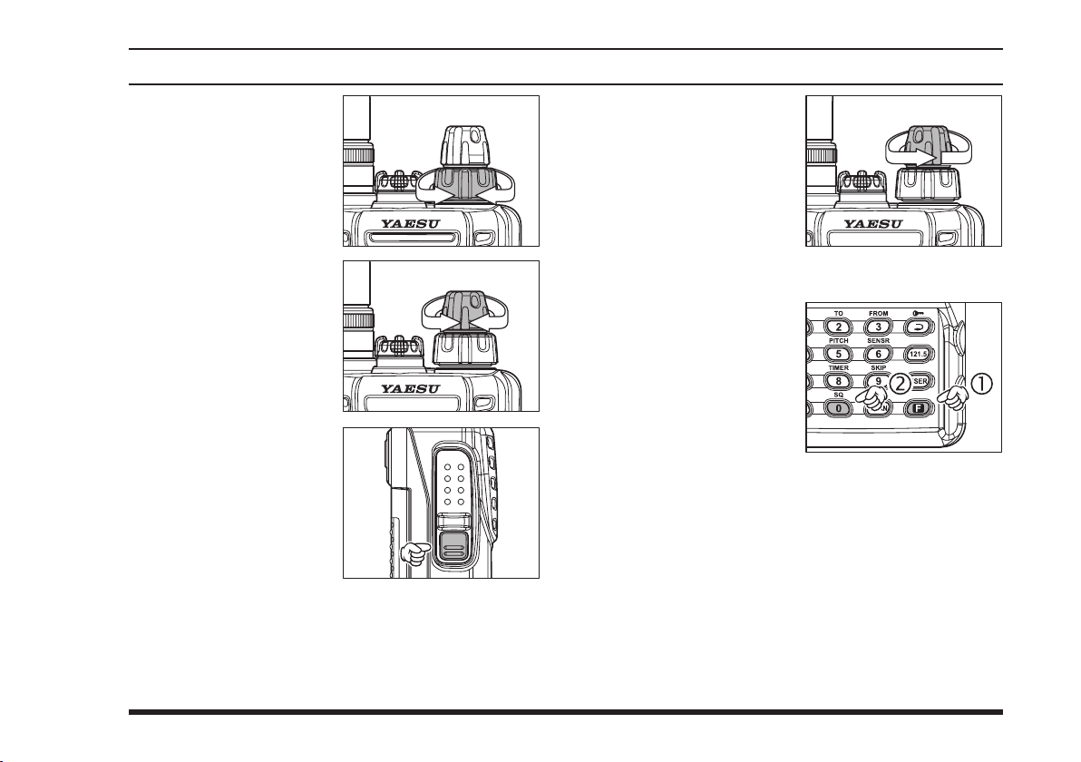
You may also turn the
t o p p an el ’s (o u t e r )
selector knob to
DIAL
choose the desired operating frequency. The
channel frequency will
appear on the LCD.
Rotate the
knob to set the volume
level. If no signal is
present, press and hold
the
MONITOR
for 2 se c on d s ; b a ck ground noise will now
be heard, and you may
use this noise to set the
VO LU ME
the desired audio level.
Press the
switch momentarily to
si lence t he no ise and
resume normal (quiet) monitoring.
VOLUME
switch
k n ob f o r
MO NITOR
To turn the radio off,
t u rn th e
kn o b fu ll y co unt erclockwise into the click
stop position.
V OL U M E
Squelch Adjustment
P r e s s t h e
m o m e n t a r i l y ,
t h e n p r e s s t h e
[0(
S Q
instantly recalls Menu
Item 01 “
is adjusts the threshold
level of the squelch circuit.
Rotate the
threshold (0 to 8) so that the receiver is just silenced.
A higher number indicates that a higher signal level
is required in order to open the squelch.
Press downward on the
your new setting.
Press the
mode.
[F]
k e y
) ]
ke y . Th i s
” which
SQL
selector knob to set the squelch
DIAL
VOLUME
switch to exit the Menu (“SET”)
PTT
knob to save
15
Page 18
FTA-310 OperATing MAnuAl
BasIc operatIon
Accessing the 121.5 MHz Emergency Frequency
The
FTA-310
Emergency Frequency. This function can be activated
even when the keypad lock function (described on page
21) is in use.
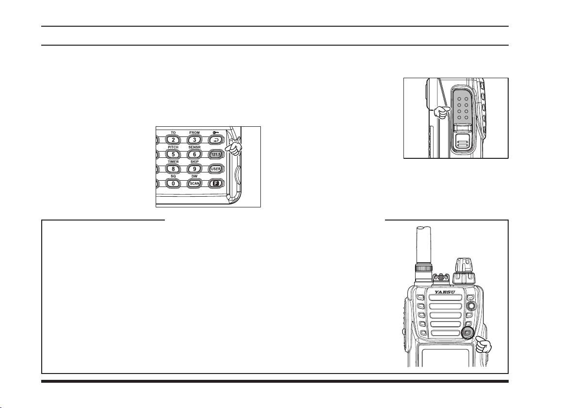
To acce s s th e Emer-
gency Frequency, press
the
mentarily.
To exit the Emergency Fre-
quency, press downward
on the
Your
eration even if it has become submerged. This unique construction includes waterproofing seals around the microphone and speaker enclosure, requiring that care be exercised
when speaking into the internal microphone.
Please refer to the illustration, and observe the location of the internal microphone. It is
important that you focus your speech in the direction of the microphone's location, so as
to ensure sufcient voice input to the radio.
If you find it difficult to utilize the
directly into the microphone, we recommend the use of the
phone (option), or an after-market aviation headset/boom microphone.
can quickly access the 121.500 MHz
[
FTA-310
]
121.5
VOLUME
k ey mo-
knob.
Operating Advice: Use of Internal Microphone
is extensively sealed against water ingress, so as to ensure reliable op-
FTA-310
conveniently and safe while speaking
Transmission
To transmit, press and hold the
into the mic r o ph on e
area of the front panel
grille in a normal voice
level.
To return to the receive
mode, release the
switch.
Speaker/Micro-
MH-44
B4B
PTT
switch. Speak
PTT
16
Page 19
FTA-310 OperATing MAnuAl
advanced operatIon
Tuning Methods
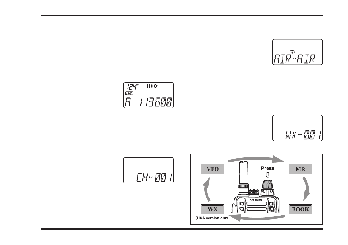
Throughout this manual, you will see references to several different frequency setting methods. Each will be
particularly useful in a particular operating situation,
and they are described below:
VFO (Variable Frequency Oscillator)
The VFO is a “ tuning di al”
sy s te m wh ich al low s y o u
to tune through the NAV or
COM bands using the
selector, the Keypad, or the scanner. The
two VFOs which are called VFO-A and VFO-B. Press
[
the
SCAN(DW
VFO-A and VFO-B. You may set VFO-A to the NAV
band, and VFO-B to the COM band, if you like.
MR (Memory Recall)
Th e MR ( Memory R ecall)
mode of the
vides the user with the ability
to store and recall as many
as 150 channels in the radio’s main memory bank.
These memory channels may also be labeled by you
with an alpha/numeric name of up to 8 characters in
length, to aid in quick identication of the channel. See
page 30 for details on creating alpha/numeric labels.
)]
key momentarily to switch between
FTA-310
DIAL
pro-
FTA-310
has
BOOK (Pre-Programmed) Memories
The Book memories are pre-
pr ogrammed , eit h er at the
fac t o r y o r by yo u r Dealer
(depending on your country’s
requirements), typically including the major COM
and NAV band station frequencies used in your area.
The Book memories can be changed by the user.
See page 44 for details.
WX (Weather Channel) Memories
Ten Weather Channels are pre-programmed at the
factory. The
automatically scan this special bank when it is selected
by the user.
FTA-310
will
(USA version only)
17
Page 20
FTA-310 OperATing MAnuAl
advanced operatIon
Reception of Weather Channel Broadcasts
(USA version only)
The
FTA-310
casts, which may assist your ight planning. The
includes a ten-channel auto-search feature, which
310
simplies access to Weather Channels when you are in
an unfamiliar location.
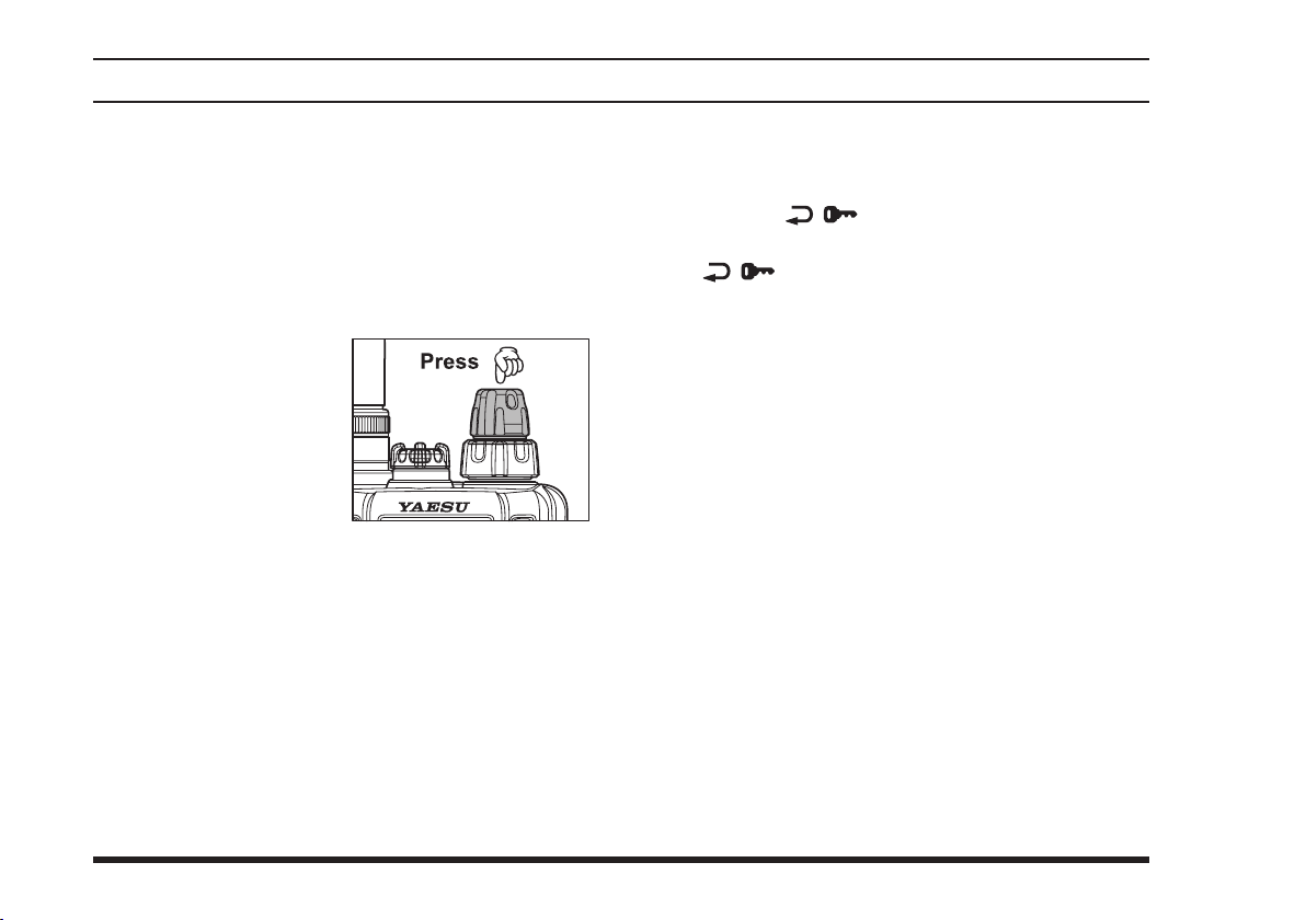
To re cei ve We a the r
Channels, press downward on the
kno b (r e peat e dly, if
necessary) to select the
Weather Channel mode.
In the Weather Channel
mode, “
The
ten standard Weather Channels, and will stop on the
rst active station found.
If there are two or more weather channels audible in
your area, you may select the alternate channel(s) by
pressing the
re-initiates the scanning process.
If there are no Weather Channels in your area, the
scanner will not stop. Press the
to stop the scanner.
can receive VHF Weather Channel broad-
switch. Pressing the
MONITOR
-
WX
FTA-310
VOLUME
” will appear on the display.
-
will now scan quickly through the
PTT
PTT
18
FTA-
switch
switch
You can also select Weather Channels manually by
rotating the
To conrm the current Weather Channel frequency,
press the
ch a ng es to fr eq u en c y in di c at i on . Pr es s th e
[ ( )]
To exit the Weather Channel mode, press downward
on the
VFO mode.
Note 1:
In the event of extreme weather disturbances, such as
storms and hurricanes, the NOAA (National Oceanic
and Atmospheric Administration) sends a weather alert
accompanied by a 1050 Hz tone and subsequent weather
report on one of the NOAA weather channels. You may
setup the Alert function when receiving the Weather
Alert signal via Menu Item 20 “
page 52 for details.
Note 2:
The Weather Channel mode memorizes the last Weather
Channel you have used, and will retain this information
until the radio is turned off.
[ ( )]
VOLUME
selector knob.
DIAL
key momentarily. The display
key again to return to normal display.
knob momentarily to return to the
,” if desired. See
WXAF
Page 21
FTA-310 OperATing MAnuAl
advanced operatIon
Monitor Switch
When listening to a very weak signal from an aircraft or
ground station, you may observe the signal disappearing
periodically as the incoming signal strength becomes too
weak to override the squelch threshold setting.
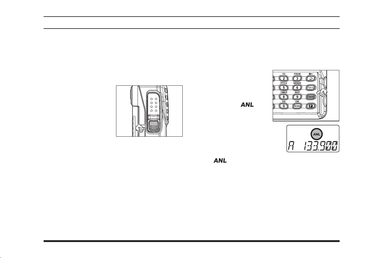
To disable the squelch temporarily, press and hold the
MONI TO R
seconds on the left side of
th e radio , jus t below the
switch. The squelch
PTT
will remain open and you
should have a better chance
of hearing weak signals.
To return to normal operation, press the
switch momentarily.
sw i t ch for 2
MONITOR
ANL (Automatic Noise Limiter) Feature
For reduction of impulse noise, such as that produced by
an engine’s ignition system, the ANL feature may prove
helpful. The ANL feature is only activated in the AM
mode.
To activ a t e t he ANL
f e a t u r e , p r e s s t h e
[
tarily. The “ ” icon
will appear on the displ a y, and you shou l d
observe a reduction in the ignition noise.
To turn the ANL feature off,
re p e a t the above st e p ; the
“ ” icon will disappear from the display.
USER
]
key momen-
19
Page 22
FTA-310 OperATing MAnuAl
advanced operatIon
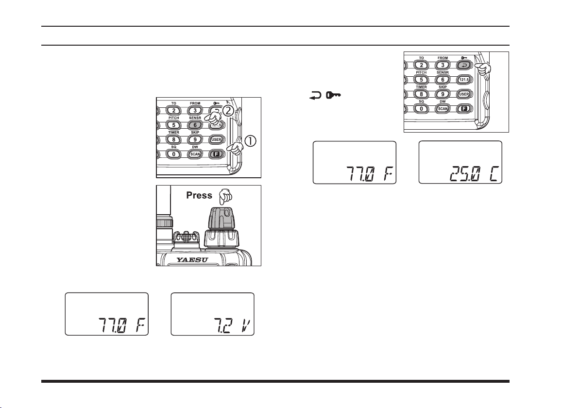
Temperature/Battery Voltage Display
The
FTA-310
side the transceiver’s case and current battery voltage.
To display these items,
press the
me ntarily, then pres s
the
The display will now
in d ica t e th e cu r re n t
temperature inside the
tra n s c e i v e r ’s ca se or
current battery voltage.
p r es s dow nw a rd on
th e
to swi t ch the dis p lay
between “current tem-
perature” and “current
battery voltage.”
can measure the current temperature in-
[F]
key mo-
[
(
6
SENSR
VO LU M E
)]
key.
kn ob
Wh en th e
display “current temperature,” pressing the
( )]
[
the tempera t u r e u ni t
between “Celsius: °C”
and “Fahrenheit: °F.”
FTA -3 1 0
key to switch
To return to the normal operation, press
[
(
6
SENSR
If the temperature display is incorrect, it can be recalibrated via Menu Item 14 “
details.
)]
again.
.” See page 51 for
TEMP
[F]
20
Page 23
FTA-310 OperATing MAnuAl
advanced operatIon
LOCK Function
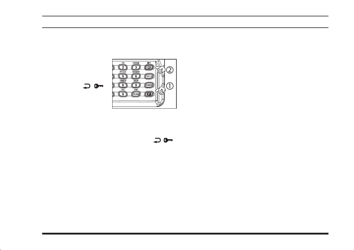
The lock function prevents accidental changes to the
frequency setting and the keypad controls.
To act i vate th e lock
feature, press the
key momentarily, then
pr e ss th e
key.
In th e LO C K mo de,
the display will show
“
-
LOCK
knob, press downward on the
touch a key on the keypad.
To turn the lock feature off, press
again.
You ca n st il l a cc e ss th e 12 1. 50 0 MH z E me r -
gency Frequency when the LOCK function is on.
Simply press the
never locks). Pressing this key also unlocks the radio.
You may choose the lockout conguration according to
your operating preferences. See page 51 for details.
[ ( )]
” when you rotate the
-
[F]
[
121.5
selector
DIAL
[ ( )]
knob, or
VOLUME
[F]
]
key momentarily (this key
Beep On/Off
The
FTA-310
audible feedback whenever a button is pressed. Each
key and button has a different beep pitch, and each function has a unique beep combination.
When you are scanning, the beeper will be heard each
time the scanner halts on a busy channel. This may be
distracting in some environments; if you want to turn the
beeper off (or back on again):
Pr ess the
VOLUME
Rotate the
05 “
Press downward on the
adjustment of this Menu item.
Rotate the
“beeper.” The selections available are on,
: Sounds a beep corresponding to a musical note.
on
DTM
oFF
When you have made your selection, press down-
ward on the
ting, and then press the
operation.
’s key/button beeper provides convenient
[F]
k ey, then press downwa rd on t h e
knob to activate the Menu (“SET”) mode.
selector knob to select Menu Item
DIAL
.”
BEEP
VOLUME
selector knob to select the desired
DIAL
: Sounds a beep corresponding to a DTMF tone.
: Disables the key beeper.
VOLUME
knob to save the new set-
PTT
knob to enable
key to exit to normal
DTM
, and
oFF
.
21
Page 24
FTA-310 OperATing MAnuAl
advanced operatIon
Receive Battery Saver Setup
An important feature of the
tery Saver, which “puts the radio to sleep” for a time
interval, periodically “waking it up” to check for activity. If somebody is talking on the channel, the
will remain in the “active” mode, then resume its “sleep”
cycles. This feature signicantly reduces quiescent battery drain, and you may change the amount of “sleep”
time between activity checks using the Menu System:
FTA-310
is its Receive Bat-
FTA-310
ABS: Automatic Battery Saver, based on activity on
the receiver.
The setting of
tion of battery capacity, but the receiver’s response time
to incoming calls will be slowed somewhat.
Note: This feature does not operate during Scan or Dual
Watch.
will promote the greatest conserva-
1:5
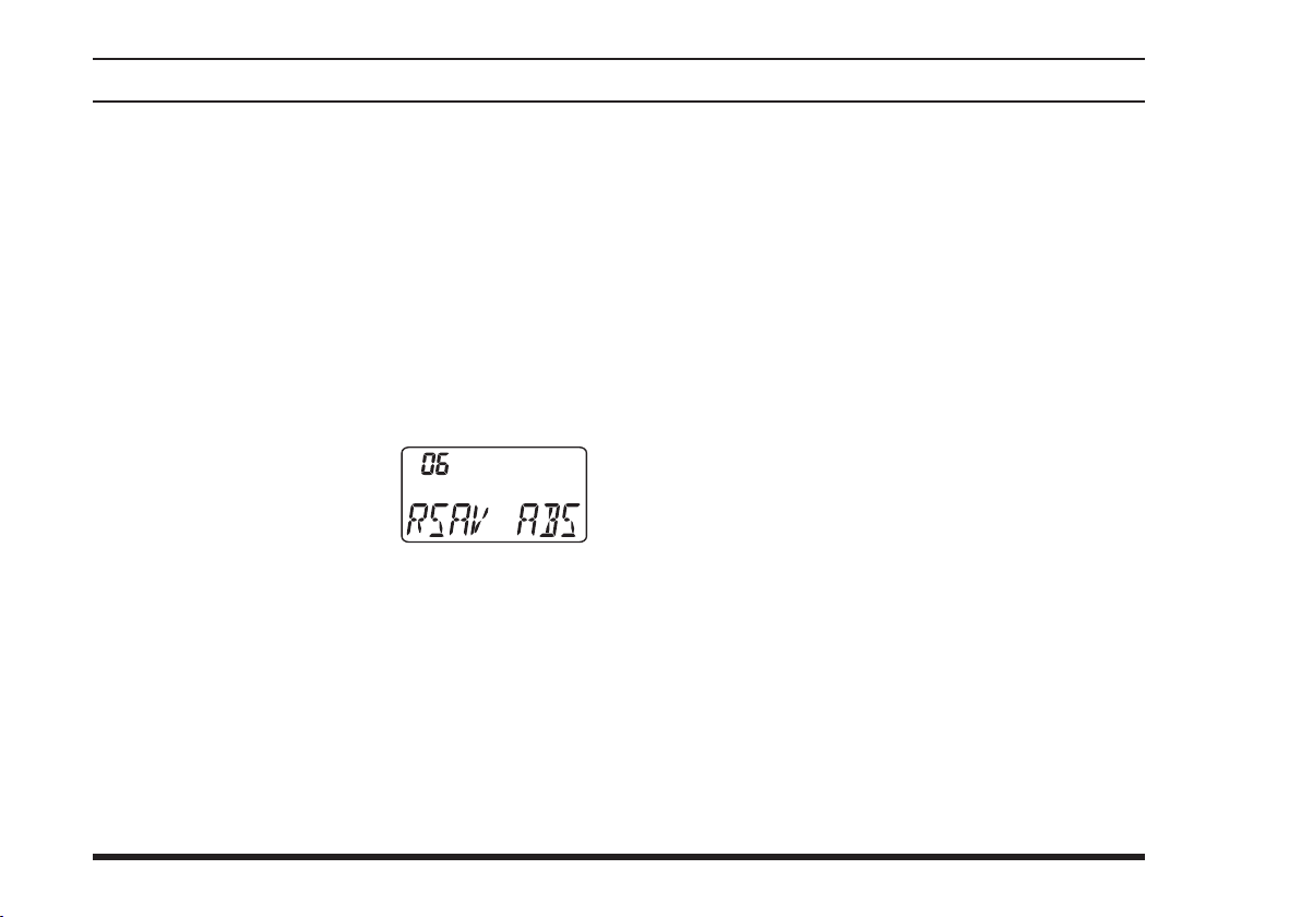
Press the
UME
Rotate the
knob to select Menu Item 06
“
RSAV
P r e s s do w n w a r d on th e
VOLUME
item.
Rotate the
“duty cycle” (receive:sleep). The selections available are
The default value is 1:1.
When you have made your selection, press down-
ward on the
ting, and then press the
operation.
[F]
key, then press downward on the
knob to activate the Menu (“SET”) mode.
se l e ct o r
DIAL
.”
knob to enable adjustment of this Menu
selector knob to select the desired
DIAL
1:1, 1:2, 1:3, 1:4, 1:5
VOLUME
knob to save the new set-
PTT
, and
key to exit to normal
22
ABS
or
VOL-
oFF
.
Page 25
FTA-310 OperATing MAnuAl
advanced operatIon
Changing the Channel Steps
The
FTA-310
lizing channel steps of 8.33/25 kHz per step.
The
FTA-310
kHz” (NAV and COM bands). If you need to change the
channel step increments, the procedure to do so is very
easy.
First set the
or VFO B and NAV or COM) on which you wish to
change the channel steps.
Press the
VOLU M E
mode.
Rotate the
knob to select Menu Item 30
“
STEP
P r e s s do w n w a r d on th e
VOLUME
item.
Rotate the
channel step size.
When you have made your selection, press down-
ward on the
ting, and then press the
operation.
’s synthesizer provides the option of uti-
is set up with default channel steps of “25
FTA-310
[F]
key, t hen press downw ard on th e
to the operating band (VFO A
k nob to act ivate the Me nu (“S E T”)
se l e ct o r
DIAL
.”
knob to enable adjustment of this Menu
selector knob to select the new
DIAL
VOLUME
knob to save the new set-
key to exit to normal
PTT
Important Note
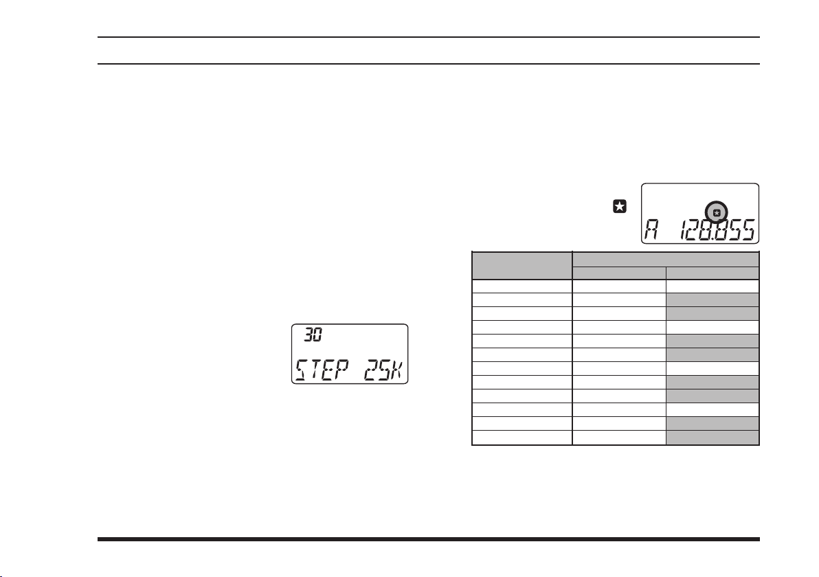
1) When you set the channel step to 8.33 kHz, the
channel display differs from actual operating frequency; see the chart below. However, the operator
(pilot, tower, control, etc) will call out the frequency
according to what the display indicates.
When y o u s e t t h e c h a n n e l
steps to 8.33 kHz, the “ ”
icon will appear in the display.
Operating
Frequency
1xx.0000 MHz
1xx.0083 MHz
1xx.0166 MHz
1xx.0250 MHz
1xx.0333 MHz
1xx.0416 MHz
1xx.0500 MHz
1xx.0583 MHz
1xx.0666 MHz
1xx.0750 MHz
1xx.0833 MHz
1xx.0916 MHz
8.33 kHz Step
1xx.005 MHz
1xx.010 MHz
1xx.015 MHz
1xx.030 MHz
1xx.035 MHz
1xx.040 MHz
1xx.055 MHz
1xx.060 MHz
1xx.065 MHz
1xx.080 MHz
1xx.085 MHz
1xx.090 MHz
Display
25 kHz Step
1xx.000 MHz
1xx.025 MHz
1xx.050 MHz
1xx.075 MHz
2) The 8.33 kHz step allows the radio to receive only,
and the transmit function is disabled.
3) The adjacent channel selectivity will be slightly degraded while receiving using 8.33 kHz channel steps.
23
Page 26
FTA-310 OperATing MAnuAl
advanced operatIon
Pitch Control
The
FTA-310
four special receiver audio responses to allow the most
comfortable and/or effective reception in noisy environments. The effect is similar to that provided by an
“Equalizer” in a stereo.
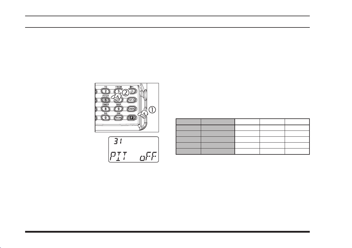
Press the
me ntarily, then pres s
the
This insta ntly recal ls
Menu It em 31 “
wh i c h selects t h e receiver audio responses.
Rotate the
knob to select desired receiver audio response. Available
selections are:
oFF
MD1
MD2
MD3
includes a feature that lets you choose
[F]
key mo-
[
(
5
PITCH
)]
DIAL
key.
”
P I T
se l e ct o r
: The re ceived a udio signal does no t pass
through the equalizer circuit.
: The received audio is passed without roll-off
on the high or low ends.
: The received audio is enhanced in the low-
and mid-range frequencies.
: The received audio is enhanced in the mid-
and high-range frequencies.
24
: The received audio is shaped per a user-
USR
configured audio response programmed via
Menu Items 26 “
“
.” The default setting enhances the
UP_H
UP_L
,” 27 “
UP_M
,” and 28
audio in the lower frequency range, and reduces the level of the higher-frequency components.
When you have made your selection, press down-
ward on the
VOLUME
ting, and then press the
knob to save the new set-
key exit to normal
PTT
operation.
selectIon
oFF
MD1
MD2
MD3
USER
response
Normal
Full Boost
Low Boost
High Boost
Default
low-range
0
+
+
–
+
mId-range
0
+
+
+
0
HIgH-range
0
+
–
+
–
Page 27
FTA-310 OperATing MAnuAl
advanced operatIon
VOX Operation
If you want to have both hands free, use the (usersupplied) Headset and activate the VOX (voice-actuated
transmit/receive switching) system.
Note: The VOX system does not function when using
just the internal microphone; an external headset must
be used.
To activate the VOX system using the Menu System:
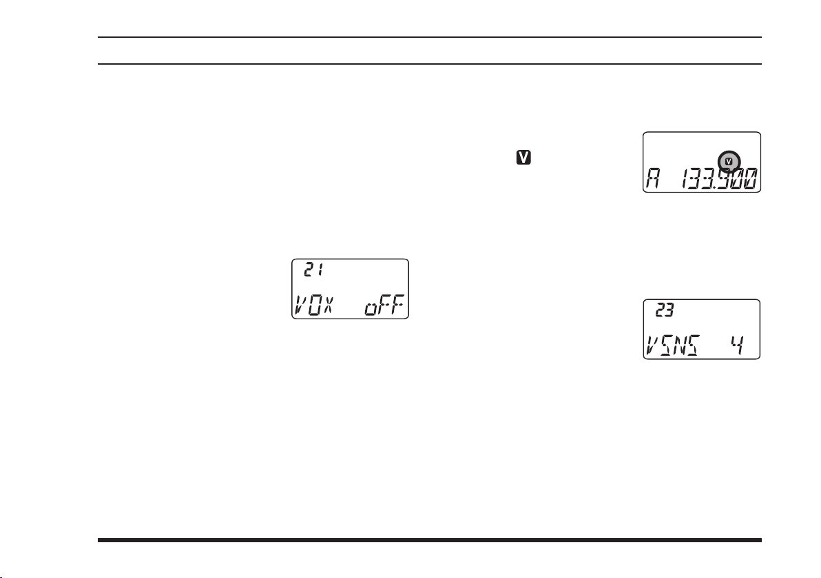
Pr ess the
VOLUME
Rotate the
knob to select Menu Item 21
“
VOX
Press downward on the
UME
Rotate the
able the VOX system).
When you have made your selection, press down-
ward on the
ting, and then press the
mal operation.
Without pressing the
microphone in a normal voice level. When you start
speaking, the transmitter should be activated automatically. When you nish speaking, the transceiver
should return to the receive mode (after a short delay).
[F]
k ey, then press downwa rd on t h e
knob to activate the Menu (“SET”) mode.
se l e ct o r
DIAL
.”
VOL-
knob to enable adjustment of this Menu item.
selector knob to select “on” (to en-
DIAL
VOLUME
knob to save the new set-
switch to exit to nor-
PTT
switch, speak into the
PTT
To cancel VOX and return to
repeat the above procedures, selecting “
4 above.
When the VOX system is activated, the “
on the display.
The
FTA-310
via the Menu, to prevent accidental transmitter activation in a noisy environment. To set the VOX Gain:
Press the
UME
Rotate the
knob to select Menu Item 23
“
VSNS
Press downward on the
UME
While speaking into the microphone, rotate the
DIAL
ter is quickly activated by your voice, without causing background noise to activate the transmitter.
When you have selected the optimum setting,
downward on the
setting, and then press the
normal operation.
” icon will appear
provides for adjustment of the VOX Gain
[F]
key, then press downward on the
knob to activate the Menu (“SET”) mode.
s el e c t o r
DIAL
.”
VOL-
knob to enable adjustment of this Menu item.
selector knob to the point where the transmit-
VOLUME
operation, just
PTT
oFF
knob
to save the new
switch to exit to
PTT
” in step
VOL-
press
25
Page 28
FTA-310 OperATing MAnuAl
advanced operatIon
Th e
FTA- 3 1 0
“Hang-Time” of the VOX system (the transmit-receive
delay after the cessation of speech) via the Menu. The
default delay is 1.0 second. To set a different delay time:
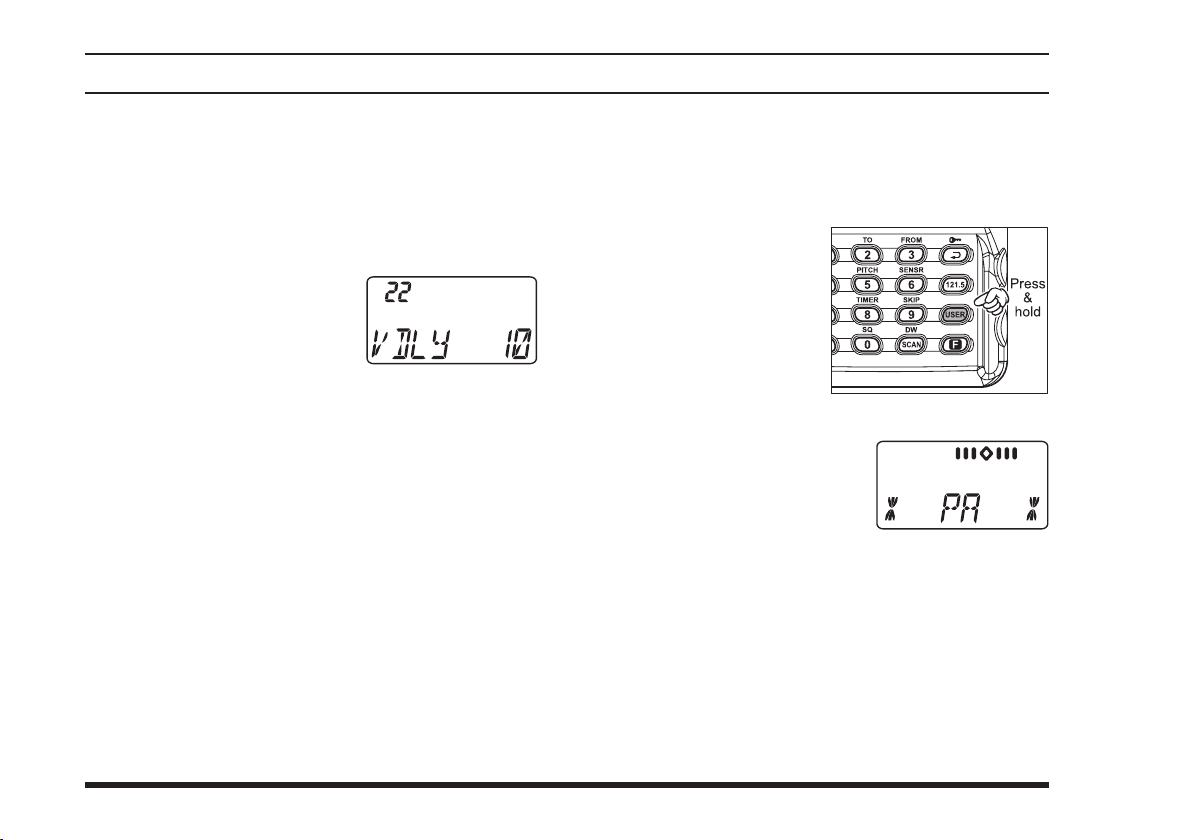
Press the
UME
Rotate the
knob to select Menu Item 22
“
VDLY
P r es s d o wn wa rd o n t he
VOLUME
item.
Rotate the
time among “05,” “10,” “15,” and “20” (representing 0.5, 1.0, 1.5, and 2.0 sec).
When you have made your selection,
ward on the
and then press the
eration.
a lso pr ovides f or ad j ustment of t he
[F]
key, then
knob
to activate the Menu (“SET”) mode.
DIAL
.”
knob
DIAL
VOLUME
press downward on the
se l e ct o r
to enable adjustment of this Menu
selector knob to select the delay
knob
to save the new setting,
switch to exit to normal op-
PTT
VOL-
press down-
PA Operation
The PA mode allows the
lic Address System when an optional
phone or other Headset/Microphone is connected.
Press and hold in the
[
onds to activate the PA
mode.
Speak through the mi-
crophone while pressing and hold in the
switch on the microphone or headset/microphone.
The “
dle
with the voice level. Rotate
the
trol the audio output level.
To exit the PA mode, press and hold in the
key again.
The
monitor feature via the Menu while using a Headset. To
select the monitor conguration:
]
USER
FTA-310
key for 2 sec-
Course Deviation Nee-
” will defect in accordance
VOLUME
provides for customization of the voice
FTA-310
PTT
knob to con-
to be used as a Pub-
MH-44
B4B
Micro-
[
USER
]
26
Press the
UME
[F]
key, then
knob
to activate the Menu (“SET”) mode.
press downward on the
VOL-
Page 29
FTA-310 OperATing MAnuAl
advanced operatIon
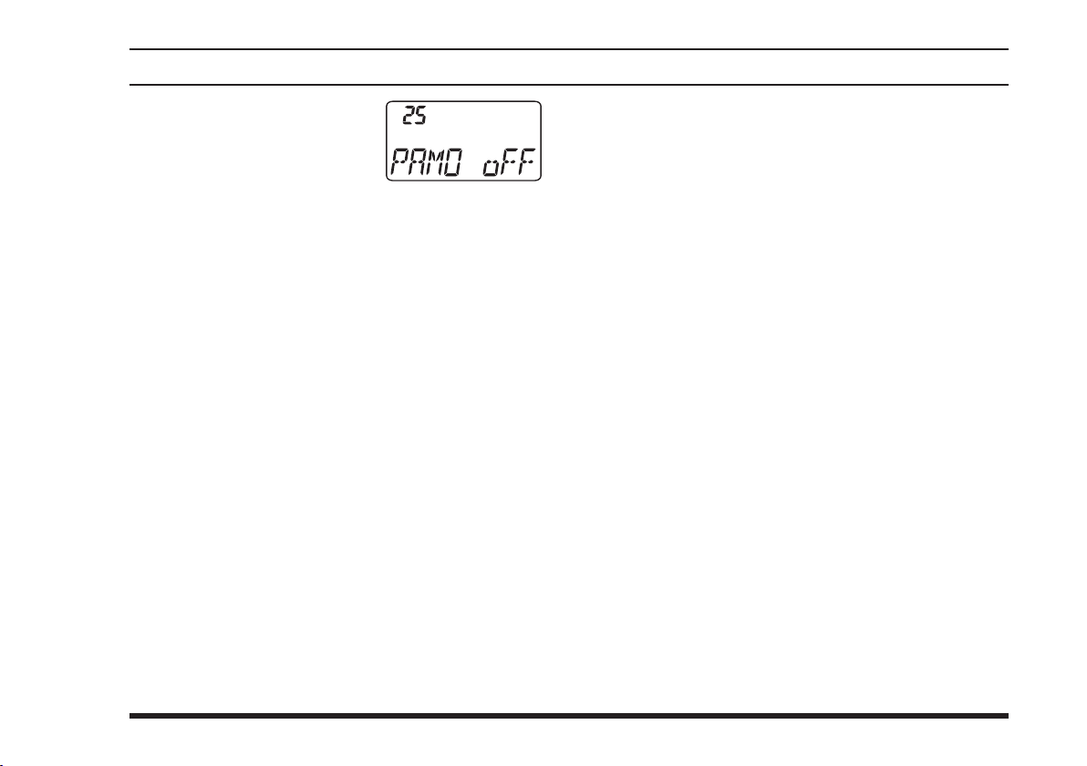
Rotate the
knob to select Menu Item 25
“
P r es s d o wn wa rd o n t he
VOLUME
item.
Rotate the
monitor mode.
oFF
PA
ALL
When you have made your selection,
ward on the
and then press the
eration.
Note: Do not activate the voice monitor feature while
using with the optional
voice monitor feature will tend to produce “howling”
due to feedback.
.”
PAMO
knob
DIAL
: Disables the monitor function at all times.
: Feeds back your voice to the headset while
you’re pressing the
: Feeds back your voice to the headset while
you’re pressing the
switch is off, you may monitor the sound
PTT
around the transceiver (the monitor will pick
up the background sound using the
internal microphone).
se l e ct o r
DIAL
to enable adjustment of this Menu
selector knob to select the desired
switch.
PTT
switch. When the
PTT
FTA-310
press down-
knob
VOLUME
PTT
to save the new setting,
switch to exit to normal op-
Microphone. The
MH-44
B4B
’s
27
Page 30
FTA-310 OperATing MAnuAl
advanced operatIon
Timer Operation
The
FTA-310
“Count Down” timer. These can be used for a variety of
time-keeping purposes.
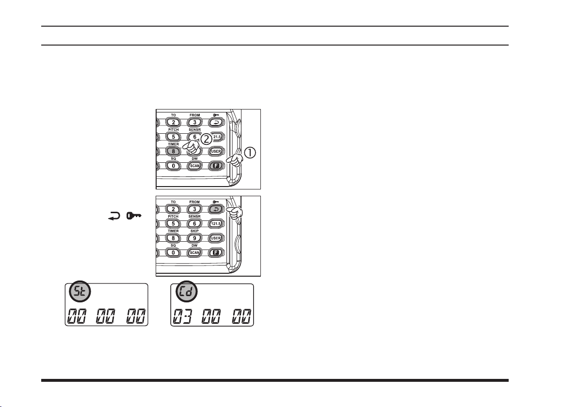
P r e s s t h e
k e y m o m e n tarily, th e n press th e
[
8
tivate the Timer Mode.
Pre s s th e
ke y toggl e the Tim e r
b e tw e e n th e “S t o p
Wa t ch ” an d “C ou nt
Down” timer modes.
is provided a “Stop Watch” timer and a
[F]
(
TIMER
)]
key to ac-
( ) ]
[
If you select the “Count Down” timer, rotate the
knob to set the values for the timer (1 minutes
DIAL
- 60 minutes).
The Timer is designed to start/stop/reset repeatedly
whenever you
knob
.
In the “Count Down” timer mode, an alert will
sound and the timer will stop when the “Count
Down” timer reaches “
To disable the Timer Mode, press
again.
press downward on the
00 00 00
.”
[F]
VOLUME
[
(
8
TIMER
)]
28
“Count Down” timer mode“Stop Watch” mode
Page 31

FTA-310 OperATing MAnuAl
Notes
advanced operatIon
29
Page 32
FTA-310 OperATing MAnuAl
memory operatIon
The
FTA-310
memories, labeled “
up t o 1 0 0 pre-progra m m e d memories, d e s i g n a t e d
“Book” Memories. The “ ” icon appears when the
“Book” Memory Mode is activated.
The Main memories and “Book” Memories can be assigned alpha-numeric names of up to eight characters.
provides 150 user-programmable “Main”
CH-001
” through “
CH-150
,” and
Memory System Operation
The
FTA-310
to store, label, and recall channel frequencies which
you may want to use frequently. You may store VFO
frequencies, Book Memory frequencies, and/or Weather
Channel frequencies (USA version only) into the Main
Memory system.
’s Main Memory system allows the user
Memory Storage
Select the desired frequency in the VFO mode, or
recall the Book Memory channel or Weather channel to be stored in the Main Memory.
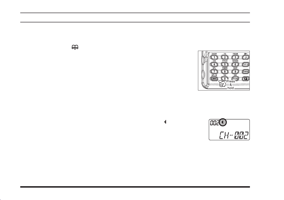
Press and hold in the
[
(
MW
SPL - W
for 2 seconds. The display will indicate “
” an d a ch a nne l
XX X
number will blink o n
the LCD.
Within ve seconds of pressing the
key, rotate the
sired memory channel number for storage.
In order to prevent writing over memory channels, a
small “
the right side of the channel
number to indicate a vacant
memory channel.
Now press and hold in the
2 seconds; you will now see blinking “A” on the
LCD. To attach an alpha/numeric name (label) to
the memory, proceed to the next step; otherwise
press and hold in the
to save the entry and exit.
” icon will appear at
)]
ke y
CH-
[
MW
selector knob to select the de-
DIAL
[
(
MW
SPL-W
[
MW
(
SPL-W
)]
for 2 seconds
(
SPL-W
)]
key for
)]
30
Page 33
FTA-310 OperATing MAnuAl
memory operatIon
To label a memory with an alpha/numeric name,
the next step is to use the
select any of the 48 available characters (including
letters, numbers, and special symbols). When the
desired rst character appears,
the
VOLUME
next character.
Select succeeding characters in the same manner,
press downward on the
tarily after each selection.
After entering the entire name (eight characters
maximum), press the
onds to save all data for the channel and exit.
Note: If you have transferred a Weather Channel directly to me mory, the “WX-001 ~ WX-010” labels
utilize the alphanumeric memory, and other labels may
not be stored. But if you go to the VFO mode, and dial
up or key in the weather station’s frequency manually,
you may then store the frequency and a custom alphanumeric label yourself.
knob
momentarily to move on to the
VOLUME
[
MW
selector knob to
DIAL
press downward on
knob
(
SPL-W
)]
key for 2 sec-
momen-
Recalling the Memories
press downward on the
if necessary, until “
pears on the display. In the MR mode, you will see
“
” and the previously selected channel number
CH-
appearing on the LCD.
Rotate the
memory channel.
You may change the title structure of the Memory
display type among:
1. Channel Indication (sequential Channel Num-
2. Frequency Indication (e.g.
3. Alphanumeric Label (e.g.
To change the Me mory display title, p r ess th e
[ ( )]
get the desired display title structure.
To exit the Memory mode, press the
knob three times to return to the VFO mode.
Note: In either the “MR” or the “Book” Memory mode,
an easy way to recall memories is to key in the memory
channel number, then press the
example, to recall memory channel #14, press
[
SCAN
DIAL
ber, e.g.
CH-001, CH-002
key repeatedly, if necessary, until you
(DW)]
.
VOLUME
-
MR
selector knob to select the desired
knob
, repeatedly
” (Memory Recall) ap-
-
, etc.);
).
DIAL
(DW)]
); or
selector
key. For
[1]
122.500
LAX FSS
[
SCAN
[4]
31
Page 34
FTA-310 OperATing MAnuAl
scannIng operatIon
The
FTA-310
1
VFO
Channel
you can talk to the station(s) on that frequency, if you like.
1: In the VFO mode, the automatic scanner is only
available in the COM band (118.000 ~ 136.975
MHz); when the scanner reaches the uppermost
frequency in the COM band, it will revert to the bottom end of the COM band and repeat the scanning
process until you cancel the scanning process.
2: USA version only.
If you wish to scan in the NAV band (108.000 ~ 117.975
MHz), you can do so manually, as described at the right.
Scanning operation is basically the same in each of the
above modes.
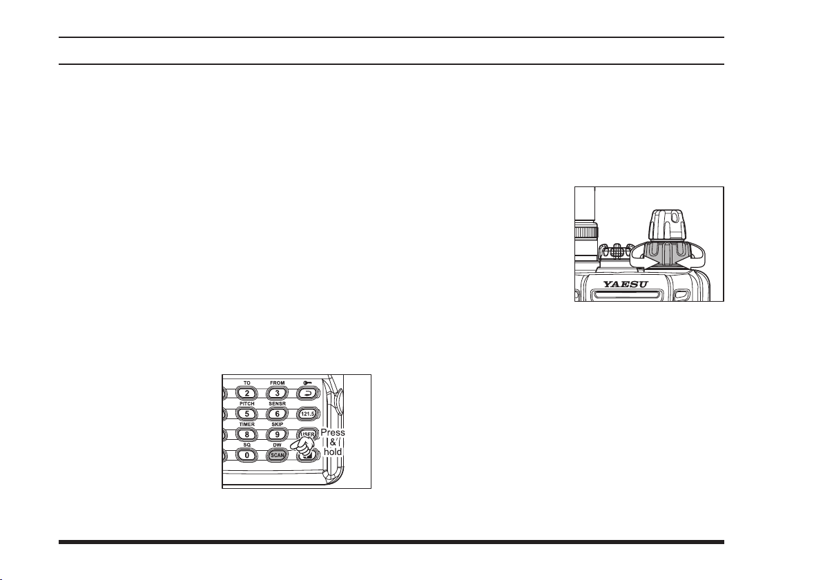
Press and hold in the
[
SCAN
2 seconds to start the
automatic scanner upward (toward a higher
frequency or a higher
channel number).
When the scanner encounters a signal, scanning
pauses and the radio remains on that channel until
allows you to scan automatically in the
, Main Memory, “Book” Memory, or Weather
2
modes.
It pauses on signals encountered, so
(DW)]
key for
32
one second after the signal disappears, after which
scanning will resume.
While the scanner remains paused on a frequency,
the decimal point of the frequency display blinks.
The display will be illuminated unless the Scan
Lamp Feature is turned off.
To change the scan di-
rection, turn the
selector knob one click
in the opposite direction.
To stop the automatic
scanner, press the
switch or
ward on the
also just press the
The
FTA-310
NAV band (108.000 ~ 117.975 MHz), because the NAV
stations (ILS, etc.) transmit constantly (thereby causing
the scanner to stop repeatedly). However, you can scan
manually in the NAV band, per the following procedure:
Press and hold the
manual scanner. Scanning will continue as long as
the key is depressed.
Release the
scanner immediately.
press down-
VOLUME
’s automatic scanner is not operational in the
[
SCAN
DIAL
PTT
[
SCAN
[
SCAN
(DW)]
knob
momentarily. You may
(DW)]
key.
(DW)]
key to stop the manual
key to start the
Page 35
FTA-310 OperATing MAnuAl
scannIng operatIon
Note: When scanning upward in frequency, when the
frequency reaches the COM Band (118.000 ~ 136.975
MHz) via manual scanning, the
the automatic scanner mode.
FTA-310
will switch to
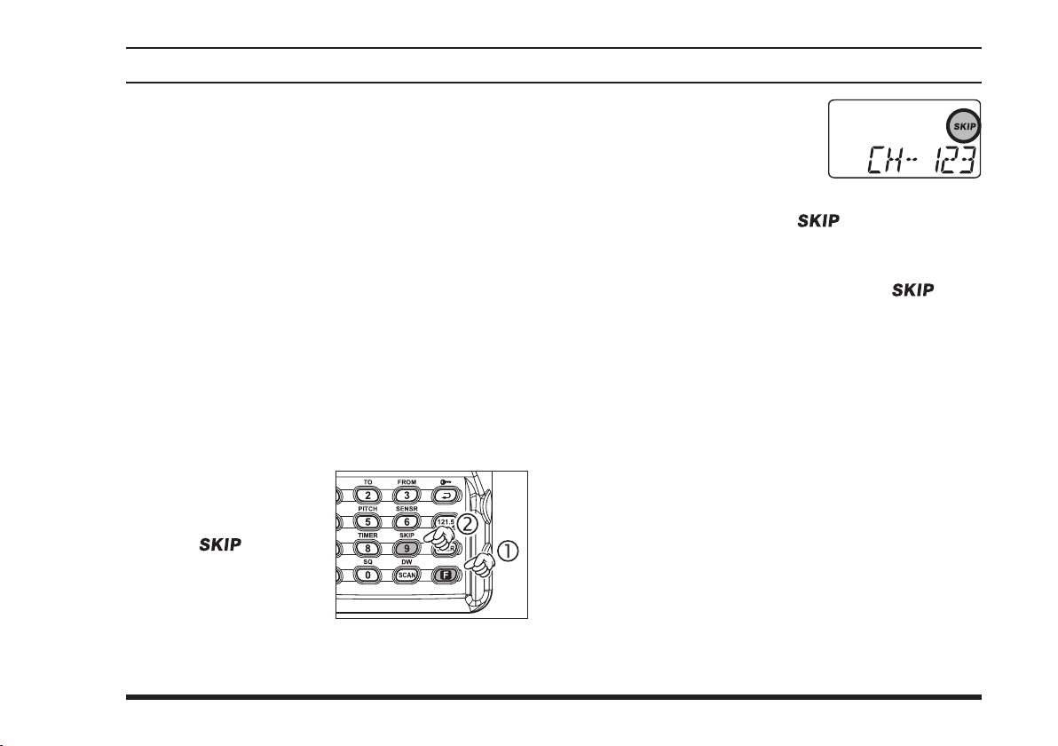
Channel-Skip Scanning
Continuous-carrier stations like ATIS (Automatic Terminal Information Service) or Weather Broadcast stations inhibit scanner operation. Since these stations are
always active, the scanner will be halted repeatedly on
their channels. Such channels can be set to be “skipped”
during Memory scanning (MR, Book or WX modes), if
you like, so as not to interfere with automatic channel
scanning:
Recall the Memory Channel to be skipped during
scanning.
[
9
(
SKIP
[
] key mo-
F
)]
.
Press the
me ntarily, then pres s
the
The “ ” icon will
ap pea r at th e up pe r
rig h t of th e ch a nnel
number, indicating that
the channel is to be ignored during scanning.
You can al s o desi g na te a
channel to be skipped while
scanning. When the receiver
is halted on a channel that
you wish to skip, press and hold the
key for 2 seconds (the “
next to the channel to be skipped).
Later, to re-enable the memory channel for scan-
ning, repeat the first two steps. The “ ” icon
will disappear by the channel you have just re-enabled.
Note: A memory set to be “skipped” is still accessible
for manual memory selection using the
knob.
[
SCAN
” icon will appear
DIAL
(DW)]
selector
33
Page 36
FTA-310 OperATing MAnuAl
dual watcH operatIon
The Dual Watch feature automatically checks for activity on a “priority” channel while you are operating on
another channel. During Dual Watch operation, the current channel and the Priority channel will each be polled
for a 500 ms interval, as the
on each channel.
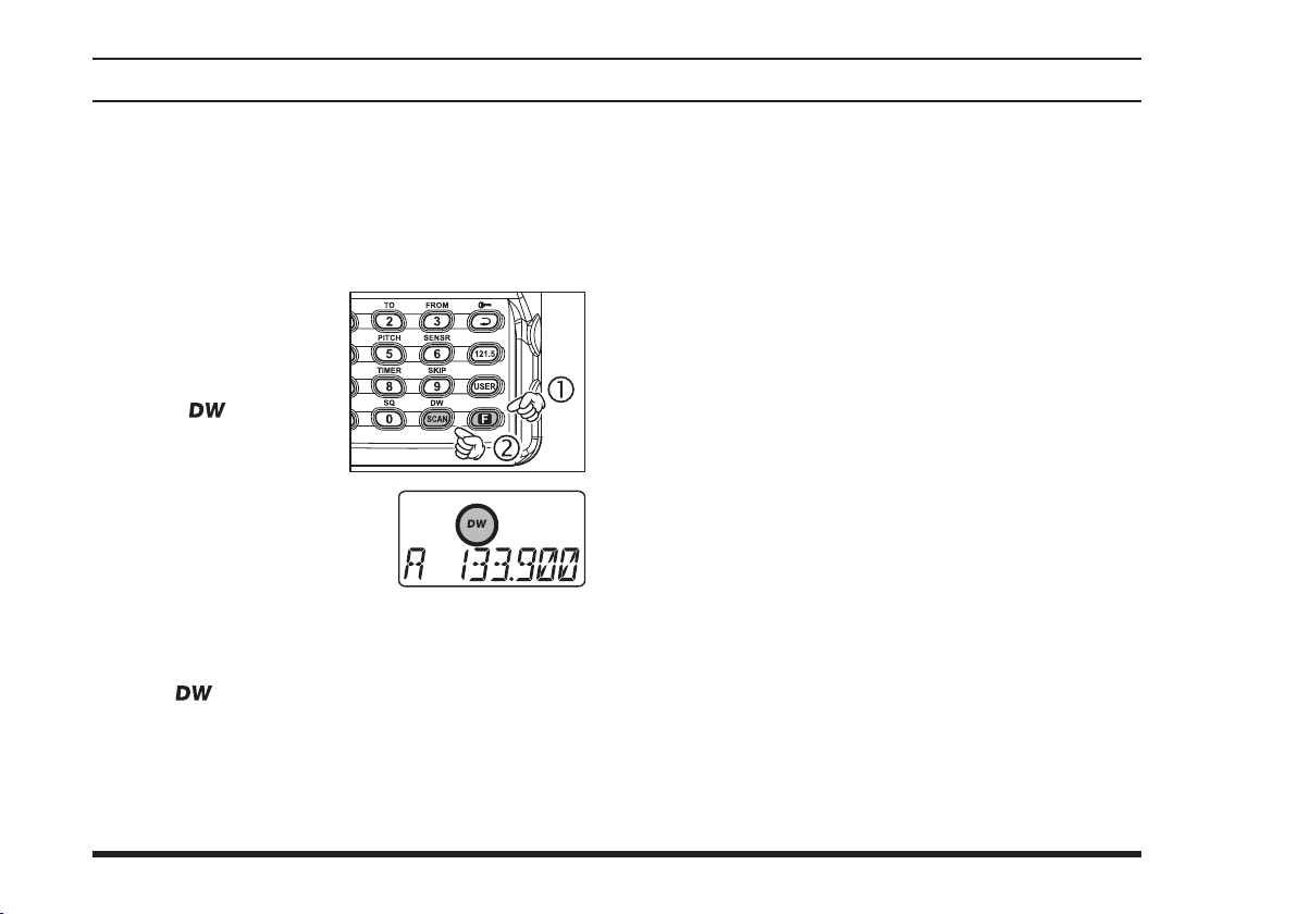
To s t a r t Dual Watch,
[
SCAN
[
] key mo-
F
(DW)]
” ic o n w i ll
switch at any
PTT
press the
me ntarily, then pres s
the
The “
appear on the display.
While receiving on the
“current” c hannel (not the
Priority channel), you may
push the
time to transmit on that channel.
When a signal is received on the Priority channel,
operation immediately shifts to the Priority channel,
the “ ” icon will blink, and the display will become illuminated.
While receiving on the priority channel, if you mo-
mentarily press the
be disabled. You may then transmit on the Priority
Channel.
FTA-310
.
switch, Dual Watch will
PTT
looks for activity
34
[F]
To stop Dual Watch, press
If you wish, you may use both the Dual Watch and
Scan features simultaneously. To do this, start the
Dual Watch rst, then start the Scanner.
: The “priority” Channel is defined as the last-used
Memory Channel (when using the VFO mode) or Memory Channel 1 (when using the Main Memory or Book
Memory modes).
[
SCAN
(DW)]
.
Page 37
FTA-310 OperATing MAnuAl
prIorIty dual watcH operatIon
Similar to Dual Watch operation (described on previous
page), Priority Dual Watch is an enhanced version which
includes the following additional features:
The receiving time interval (ratio) between the cur-
rent channel and the Priority channel may be customized via Menu Item 09 “
for details.
Irrespective of which channel is currently being re-
ceived, when the
will always occur on the Priority channel.
Before initiating Priority Dual Watch, Menu Item 10
“
DWMD
stead of “DW: Dual Watch”). See page 50 for details.
” must be set to the “
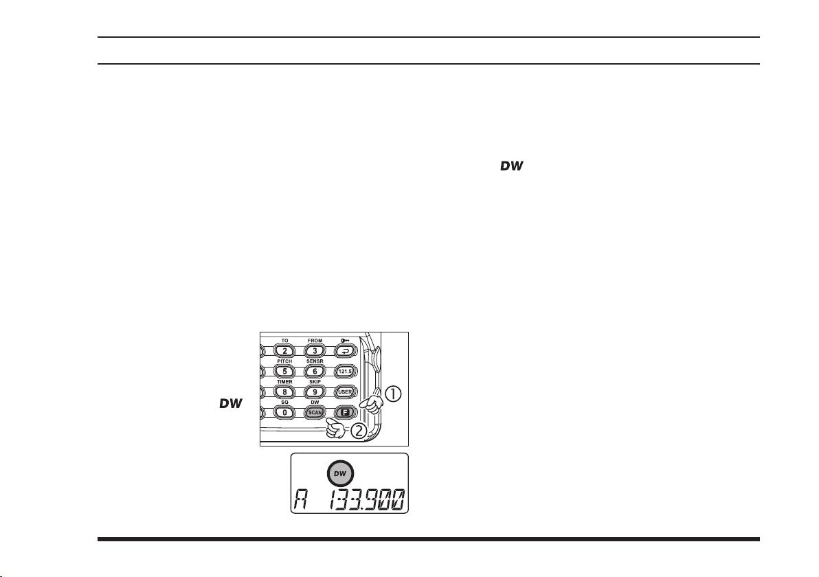
To start Priority Dual
Watch, press the
key momentarily, then
p r e s s t h e
(
) ]
D W
icon will appear on the
display.
While receiving on the “cur-
rent” (non-Priority) channel,
pressing the
causes the radio to switch to
[
. Th e “ ”
PTT
button is pushed transmission
PTT
PRI
[
]
F
S C A N
button once
.” See page 49
PRTM
: Priority” mode (in-
the Priority channel and cancels Dual Watch. Press
the
channel.
When a signal is received on the Priority channel,
reception immediately shifts to the Priority channel,
the “ ” icon will blink, and the display will become illuminated unless the Scan Lamp Feature is
turned off.
While receiving on the priority channel, if you
momentarily press the
Watch will be disabled. You may then transmit on
the Priority Channel.
To stop Priority Dual Watch, press
(DW)]
button again to transmit on the Priority
PTT
button, Priority Dual
PTT
[F]
.
[
SCAN
35
Page 38
FTA-310 OperATing MAnuAl
vor navIgatIon
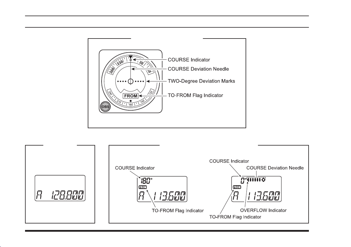
General VOR Equipment
COM Band
(118.000 - 136.975 MHz)
36
NAV Band (108.000 - 117.975 MHz
DVOR MODE CDI MODE
)
Page 39
FTA-310 OperATing MAnuAl
vor navIgatIon
To Select the DVOR Mode
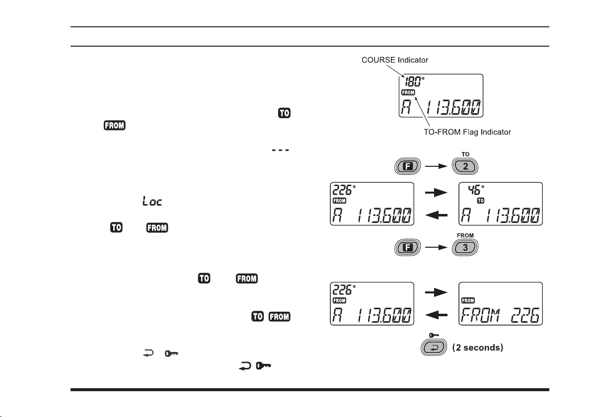
When entering the NAV band (108.000 - 117.975
MHz), the
matically. The “
at the upper left corner on the display, and the “
or “
Indicator” eld on the display.
Note: The “Co urse Ind ICator” indicates “ ”
when either your aircraft is too far away from the VOR
station or the frequency is not correctly set to that of
the VOR station. Conversely, the “Course Indicator”
will indicate “
nel. The
The “
er the VOR navigation information is based on a
course leading to the VOR station or leading away
from the VOR station.
To change the flag from “ ” to “ ” or vice
versa, press the
[
(
3
FROM
The small “Cou rs e Ind IC ator ” and “ / ”
flag indicators may be toggled to the larger “Frequency” portion of the display. To do this, press and
hold in the
to the larger display area. Press the
momentarily again to return to the smaller displays.
FTA-310
” indicator will appear below the “Course
FTA-310
” or “ ” ag indicators tell you wheth-
)]
or
[
selects the DVOR mode auto-
Course IndICator” eld will appear
” when receiving a localizer chan-
cannot decode a localizer signal.
[F]
key momentarily, then press the
[
(TO)]
2
( )]
key, respectively.
key for 2 seconds to toggle
[ ( )]
”
key
37
Page 40
FTA-310 OperATing MAnuAl
Flying to a VOR Station
The
FTA-310
course to a VOR station.
Select a VOR station on your aeronautical chart and
turn the
directly with the keypad) to the frequency of the
VOR station.
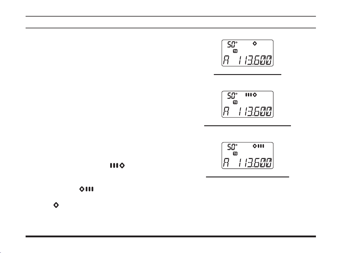
To indicate the deviation between your current ight
path and the desired course, press the
mentarily, then press the
to the CDI (Course Deviation Indicator) mode. The
“Course devIatIon arrow” will appear above the
frequency eld on the display when your aircraft is
off the direct course to the VOR station.
When your aircraft is off course to the right, the
Course Deviation Arrow display will show bars to
the left side of the diamond (“
aircraft is off course to the left, the Course Deviation Arrow display will show bars to the right side
of the diamond (“
no bars appear on either side of the CDI “Diamond”
(only “
rect).
To return to the DVOR mode, press the
mentarily, then press the
can indicate the deviation from the direct
selector knob (or enter the frequency
DIAL
[
(
)]
4
”). Correct your course until
”) will be visible when the heading is cor-
[
(
1
DVOR
key to change
CDI
”). When your
)]
38
vor navIgatIon
[F]
key mo-
[F]
key mo-
key.
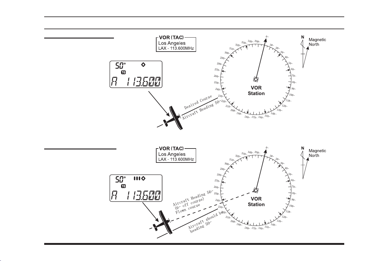
The Aircraft is “ON COURSE”
OFF COURSE to the “right” 6 degrees
OFF COURSE to the “left” 6 degrees
Page 41
FTA-310 OperATing MAnuAl
The Aircraft is “ON COURSE”
The Aircraft is “OFF COURSE”
vor navIgatIon
39
Page 42
FTA-310 OperATing MAnuAl
vor navIgatIon
Entering a Desired Course
The
FTA-310
viation from the desired course, not only the deviation
from the path to the VOR station.
Set the frequency to the desired VOR station.
Change the “
not in that mode already.
Press
mode.
Set the desired course to the VOR station using the
DIAL
quired; e.g. for 47°, press
Note 1:
The (“
on the display when your aircraft is off the desired
course.
Note 2:
When your heading is correct, the ABCS function
may be more useful than the course input option
The Course Deviation Arrow points to the right
when your aircraft is off course to the left, and it
points to the left when your aircraft is off course to
the right.
can also be congured to indicate the de-
” or “ ” ag to “ ”, if it is
[F]
selector knob or keypad (three digits are re-
[
(
)]
key to change to the CDI
CDI
[0]
[4]
[7]
).
4
”) or (“ ”) indication will appear
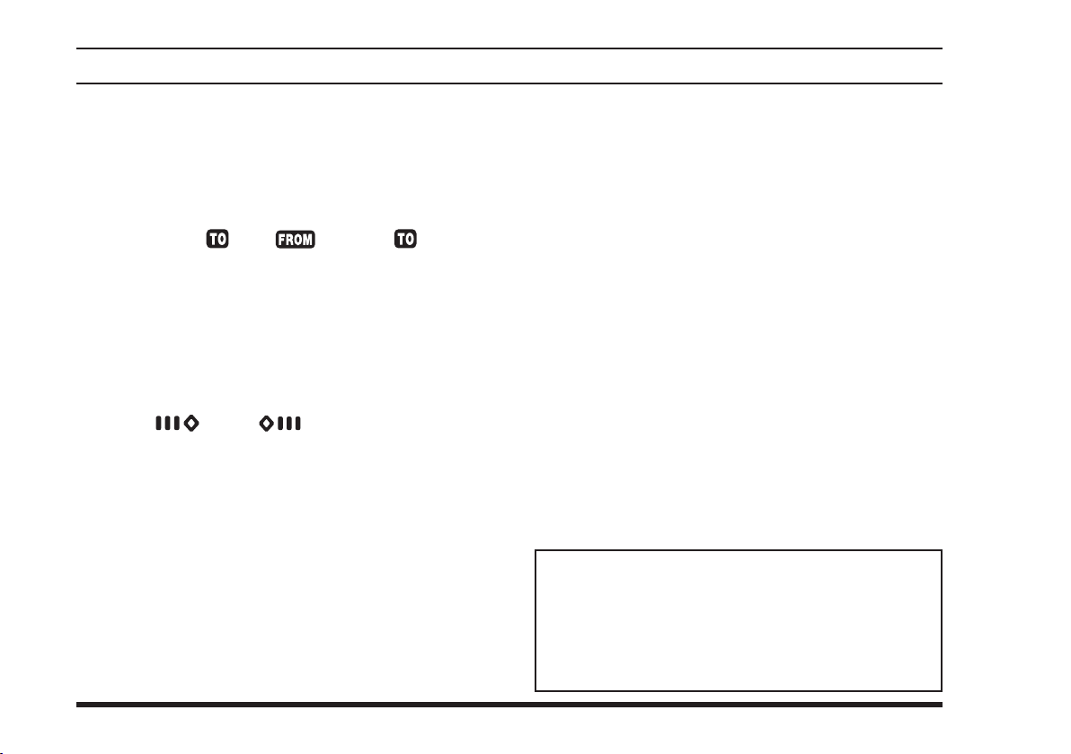
Note 1:
To get back on course, y right more than the number of
degrees indicated by the Course Deviation Arrow.
Note 2:
If the overow indicator “” appears on the right side,
select a heading plus 10 degrees to the desired course;
if the overflow indicator “” appears on the left side,
select a heading minus 10 degrees.
ABCS Mode
In the CDI mode, the Auto Bearing Center System
(ABCS) adds or subtracts the number of degrees indicated by the CDI from the Omni Bearing Selector
(OBS).
40
Page 43
FTA-310 OperATing MAnuAl
vor navIgatIon
Position Cross-checking
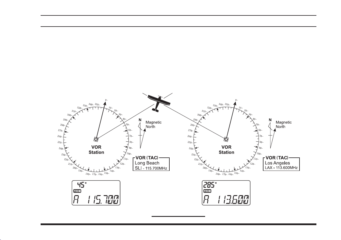
Select two VOR stations on your aeronautical chart.
Set the frequency of one of the VOR stations in the
DVOR mode. The course indicator will show the
course deviation from the VOR radial. Note the radial you currently are on.
Now set the frequency of the other VOR station in
the DVOR mode. Note the radial from the station
you are on.
Extend the radials from each VOR station on the
chart. Your aircraft is located at the point where the
lines intersect.
Cross-checking Position
41
Page 44
FTA-310 OperATing MAnuAl
vor navIgatIon
Split Operation
The split operation feature allows you to transmit a call
to a Flight Service Station using the COM band frequencies, while receiving a VOR station (in the NAV band).
VOR stations equipped with this capability typically are
shown, on navigation charts, with the voice calling frequency in parenthesis above the navigation frequency.
Programming a Transmit Frequency
Press downward on the
if necessary, to select the VFO mode.
Set a NAV band (108.000 - 117.975 MHz) frequen-
cy using the
Press the
(
SPL-W
transmit frequency will appear on the display.
Now set your radio’s transmit frequency, where the
Flight Service Station will be listening for calls, us-
ing the
Press and hold in the
onds to save the transmit frequency and return to the
NAV band frequency.
Note: You have now stored the separate transmit frequency, but you have not yet activated the split-frequency function; go on to the next section.
DIAL
[F]
key momentarily, then press the
)]
key. The “ ” icon will blink, and the
selector knob or keypad.
DIAL
VOLUME
selector knob or keypad.
[
(
MW
SPL-W
knob
, repeatedly
)]
key for 2 sec-
[
MW
Operating in the Split Mode
It is assumed that you have already set the desired
VOR station’s frequencies (in the NAV band) per
the above instructions.
(
SPL
[F]
key momentari-
switch to return to the receive
PTT
)]
again.
[
(
)]
7
SPL
switch to transmit on the
PTT
Press the
ly, then press the
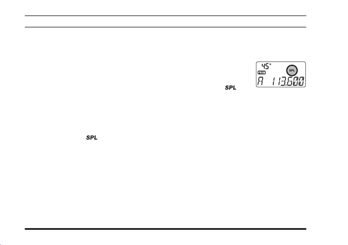
key to turn on t h e “Split”
fu n c t i on. Th e “ ” i c o n
will appear on the display.
Press and hold in the
split transmit frequency.
Release the
mode.
To dis a b le the “Sp l i t” funct i o n, press
[
7
Note: A split frequency can be programmed into each
memory channel independently. Set a transmit frequency before programming the memory channel, if desired.
The split function on/off setting can also be programmed
into a memory channel.
[F]
42
Page 45

FTA-310 OperATing MAnuAl
programmIng tHe user Key assIgnments
Default
mary” (press) and “Third” (press and hold in) function
of the front panel’s
may be changed by the user, if you wish to utilize another function on this key.
To program the function assigned to the
FTA-310
Press the
knob
UME
Rotate the
congured #18 “
function, or #19 “
function.
functions have been assigned to “Pri-
[
[F]
key, then
to activate the Menu (“SET”) mode.
knob to select the Menu Item to be
DIAL
KEY1
]
USER
key at the factory. These
[
USER
press downward on the
” which is tied to the primary
” which is tied to the third
KEY2
]
key:
VOL-
Press downward on the
ly, then rotate the
you wish to assign to the
When you have made your selection,
ward on the
then press the PTT switch to exit the Menu (“SET”)
mode.
The available selections include:
: Receiver Automatic Noise Limiter (on)
ANL
: Public Address Mode (see page 26)
PA
: Pitch Control (see page 24)
PIT
: Disables the key
no
VOLUME
VOLUME
knob to select the function
DIAL
[
USER
knob
knob
momentari-
]
key.
press down-
to save the new setting,
no/ANL/PA/EQ
43
Page 46
FTA-310 OperATing MAnuAl
FIeld programmIng mode
The
FTA-310
store, label, and recall channel frequencies which you
may want to use frequently while the
Field Programming mode.
Memory Storage into the Book Memory
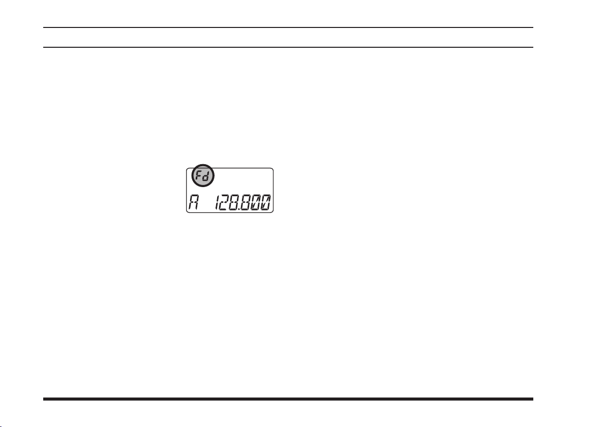
Press and hold the
while turning the radio on, to activate the Field Pro-
gramming Mode. The “Fd” icon will appear in the
upper left-hand corner of the
LCD to conrm that you are
in the F i e l d Progr a m ming
mode.
Select the desired frequency to be stored in the
Book Memory.
Press and hold in the
onds. The display will indicate “
channel number will blink on the LCD.
Within ve seconds of pressing the
key, rotate the
sired memory channel number for storage.
’s Book Memories also allow the user to
FTA-310
switch and
PTT
[
(
MW
SPL-W
-
BOOK
[
selector knob to select the de-
DIAL
is in the
VOLUME
)]
key for 2 sec-
” and a
-
(
MW
SPL-W
knob
)]
[
Now press and hold in the
2 seconds; you will now see a blinking “A” on the
LCD. To attach an alpha/numeric name (label) to
the memory, proceed to the next step; otherwise
press and hold in the
onds to save the entry and exit.
To label a memory with an alpha/numeric name, the
next step is to use the
any of the 48 available characters (including letters,
numbers, and special symbols). When the desired
rst character appears, press down on the
knob momentarily to move on to the next character.
Select succeeding characters in the same manner,
pressing down on the
after each selection.
After entering the entire name (eight characters
maximum), press the
onds to save all data for the channel.
Repeat this procedure to store additional frequencies
into the Book Memory section, as desired.
Turn the radio off, then turn the radio back on again
to begin normal operation.
[
MW
DIAL
VOLUME
[
MW
(
MW
SPL-W
(
SPL-W
selector knob to select
knob momentarily
(
SPL-W
)]
key for
)]
key for 2 sec-
VOLUME
)]
key for 2 sec-
44
Page 47

FTA-310 OperATing MAnuAl
cpu resettIng
In some instances of erratic or unpredictable operation,
the cause may be corruption of data in the microprocessor (due to static electricity, etc.). If this happens, resetting of the microprocessor may restore normal operation. Note that all memories will be erased if you do a
complete microprocessor reset, as described below.
To clear all memories and other settings to factory defaults:
Turn the radio off.
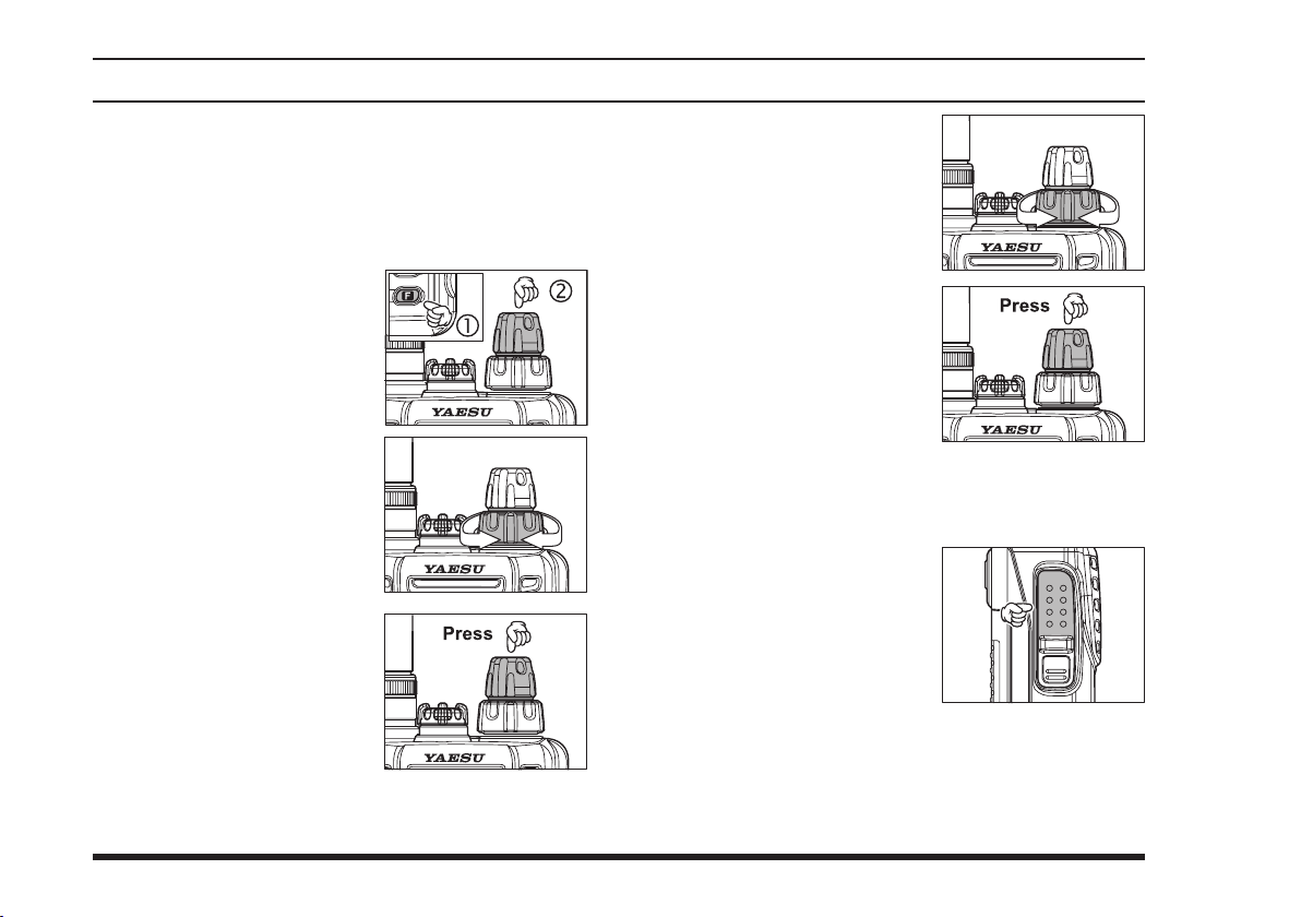
Press down and hold in the
MONITOR
button, while turning the radio on.
VOLUME
knob, and the
45
Page 48
FTA-310 OperATing MAnuAl
menu
(
“
set”) mode
The Menu system allows certain aspects of your radio’s
conguration to be customized for your personal operating convenience. We do not recommend that any of the
default settings be changed, however, until you are thoroughly familiar with the operation of the
1. Pre s s th e
press down on the
UME
Menu (“SET”) mode.
2. Rotate the
kn o b to s e l e c t the Menu
item (feature) you wish to
view and/or modify.
3. Once you have selected the
desired Menu Item, press
dow n on th e
knob once to enable adjust-
me n t of this Menu item .
The current setting value
will be blinking.
[F]
ke y, th en
VOL-
knob to activate the
selector
DIAL
VO L UM E
FTA-310
.
4. Rotate the
knob to change the setting
of the item (“on” to “
etc.).
5. Press down on the
k no b to sa ve your
UME
new setting.
6. If you need to change more than one Menu item,
repeat steps 2 - 5.
7. Press the
ex i t th e Me n u (“ S ET ” )
mode.
DIAL
PTT
selector
,”
oFF
VOL-
s w i tch to
MENU Listing
A listing of the Menu items available via the SET mode
may be found on the next page.
46
Page 49
FTA-310 OperATing MAnuAl
Menu Item
Menu No.
SQL
01
MCLR
02
RESM
03
SCNL
04
BEEP
05
RSAV
06
LAMP
07
SFT
08
PRTM
09
DWMD
10
POBP
11
IMIC
12
EMRG
13
TEMP
14
UNIT
15
TOT
16
DIMM
17
KEY1
18
KEY2
19
WXAF
20
VOX
21
VDLY
22
VSNS
23
HPLV
24
PAMO
25
UP_L
26
UP_M
27
UP_H
28
LOCK
29
STEP
30
PIT
31
(
menu
“
set”) mode
Function
Squelch Level Setting.
Memory Channel Clear (“MR” memory only).
Scan-Resume Mode Setting.
Scan Lamp On/Off (while paused).
Keypad Beeper On/Off.
Selects the Receive-mode Battery Saver “sleep” ratio.
Display and Keypad Illumination Mode.
CPU Clock Shift.
Selects the Priority Checking Time.
Selects the Dual Watch/Priority Function.
Select the Power on Beep.
Internal Microphone On/Off.
Emergency channel On/Off.
Correcting the thermometer setting.
Selects the measurement units for the temperature sensor.
Setting of the Time-Out Timer countdown time.
Setting of the display brightness level.
Programming the primary (momentary press mode) [USER] key assignment.
Programming the third (press and hold mode) [USER] key assignment.
Selects the Alert functions when receiving the Weather Alert Signal on the WX channel.
Enables/disables VOX operation.
Selects the VOX delay (“hang”) time.
Sets the VOX sensitivity.
Sets the Headphone audio level.
Enables/disables the External Speaker while utilizing the PA function.
Sets the low-frequency audio response for the user-customized receiver audio tone pitch control.
Sets the mid-range audio response for the user-customized receiver audio tone pitch control.
Sets the high-frequency audio response for the user-customized receiver audio tone pitch control.
Selects the control locking lockout combination.
Selects the synthesizer steps on the Air band.
Selects the Tone Pitch (equalizer) circuit of the audio amplier in the receiver.
Available Values
0 ~ 8
–
5S / CAR
on / oFF
on / DTM / oFF
1:1 ~ 1:5 / oFF / ABS
KEY / oFF / CNT
on / oFF
05 / 10 / 15 / 20 / 25 / 30
DW / PRI
MD1 / MD2 / MD3 / oFF
on / oFF
on / oFF
–127 ~ +127
°F / °C
1 / 3 / 5 / oFF
LV1 ~ LV4
no / ANL / PA / PIT
no / ANL / PA / PIT
BP / LED / B+L / oFF
on / oFF
05 / 10 / 15 / 20
1 ~ 8
0 ~ 7
oFF / PA / ALL
+ / – / oFF
+ / – / oFF
K / KD / P / PD / PK / PKD / D
oFF / MD1 / MD2 / MD3 / USR
+ / – / oFF
25 kHz / 8 kHz (8.33 kHz
)
Default
6
–
5S
on
on
1:1
KEY
oFF
20
DW
MD1
oFF
on
000
°F
oFF
LV3
ANL
PA
oFF
oFF
10
4
6
oFF
+
oFF
–
K
25 kHz
MD1
47
Page 50

FTA-310 OperATing MAnuAl
menu
(
“
set”) mode
01 [SQL
Function: Squelch Level Setting.
Available Values: 0 ~ 8
Default Setting: 6
Select a setting for this Menu item which just silences
the receiver when no signal is present. Use the lowest
setting which will keep the receiver quiet between incoming transmissions.
02 [MCLR
Function: Memory Chann el Clear (“MR” memory
only).
To clear a Memory channel:
Select the Menu Item
Press down on the
Press down on the
Important Notice: An “erased” channel cannot be restored, and “
“Priority Channel” operation.
]
]
.
MCLR
VOLUME
selector knob to recall the memory channel to
DIAL
be erased.
VOLUME
Memory channel (the Memory channel number will
return to “
”).
001
CH-001
” cannot be erased, as it is used for
knob, then rotate the
knob to clear the
03 [RESM
Function: Scan-Resume Mode Setting.
Available Values: 5S/CAR
Default Setting: 5S
“5S” (5-Second Pause) mode: the scanner will halt
for ve seconds only, after which scanning will resume
(whether or not the other station is still transmitting).
“CAR” (Carrier Drop) mode: the scanner will remain
halted for as long as there is a carrier present on the
channel; after the carrier drops at the end of the other
station’s transmission, the scanning will resume.
04 [SCNL
Function: Scan Lamp On/Off (while paused).
Available Values: on/oFF
Default Setting: on
If you set this function to “on,” the lamp will be illuminated whenever the scanner pauses. The lamp will go off
automatically when scanning resumes.
]
]
48
Page 51

FTA-310 OperATing MAnuAl
menu
(
“
set”) mode
05 [BEEP
Function: Keypad Beeper On/Off.
Available Values: on/DTM/oFF
Default Setting: on
on: Sounds a beep corresponding to a musical note.
DTM: Sounds a beep corresponding to a DTMF tone.
off: Disables the key beeper.
If you do a lot of scanning, you may wish to set this
Menu item to “oFF,” as the Beeper will be heard each
time the scanner pauses.
06 [RSAV
Function: Selects the Receive-mode Battery Saver
“sleep” ratio.
Available Values: 1:1 ~ 1:5/oFF/ABS
Default Setting: 1:1
The setting of 1:5 will promote the greatest conservation
of battery capacity, but the receiver’s response time to
incoming calls will be slowed somewhat.
ABS: Automatic Battery Saver, based on activity on
Note: This feature does not operate during Scan or Dual
Watch.
]
]
the receiver.
07 [LAMP
Function: Display and Keypad Illumination Mode.
Available Values: KEY/oFF/CNT
Default Setting: KEY
“KEY” mode: The illumination lamp will be activated
“oFF” mode: Disables the illumination lamp.
“CNT” mode: Illuminates the Display/Keypad continu-
08 [SFT
Function: CPU Clock Shift.
Available Values: on/oFF
Default Setting: oFF
This function is only used to move a spurious response
“birdie” should it fall on a desired frequency. Consult
your YAESU dealer for details regarding this function.
09 [PRTM
Function: Selects the Priority Checking Time.
Available Values:
Default Setting: 20 (2 seconds)
This Menu item allows you to dene how often the Priority Channel will be checked for activity.
Note: The Dual Watch Polling time is 500 mS (xed).
]
for 5 seconds when any front panel key
or the
the
DIAL
ously.
VOLUME
knob is rotated.
knob is pressed, or if
]
]
05/10/15/20/25/30 (0.5/1/1.5/2/2.5/3 sec.)
49
Page 52

FTA-310 OperATing MAnuAl
menu
(
“
set”) mode
10 [DWMD
Function: Selects the Dual Watch/Priority Function.
Available Values: DW/PRI
Default Setting: DW
“DW” mode: The
“PRI” mode: The
11 [POBP
Function: Select the Power on Beep.
Available Values: MD1/MD2/MD3/oFF
Default Setting: MD1
Note: You will hear the different selections as you rotate
the
DIAL
]
FTA-310
feature when you press
(DW)]
.
FTA-310
feature when you press
(DW)]
.
will activate the Dual Watch
will activate the Priority
]
selector knob.
[F]
[F]
[
SCAN
[
SCAN
12 [IMIC
Function: Internal Microphone On/Off.
Available Values: on/oFF
Default Setting: oFF
This controls the status of the radio’s internal microphone when an external microphone (such as the
B4B
44
nected via the
applications, set 12
(this disables the internal microphone). The internal microphone will still function normally when the external
microphone is disconnected.
13 [EMRG
Function: Emergency channel On/Off.
Available Values: on/oFF
Default Setting: on
This controls the operation of the Emergency
key. When set to “oFF,” this key will not function. You
can still use the frequency 121.5 MHz either by entering
it on the keypad in the VFO mode, or by recalling it on a
previously-stored memory channel.
]
Speaker Microphone or an aviation headset con-
Headset Cable) is in use. In most
CT-96
[
]
to “oFF” for proper operation
IMIC
]
[
121.5
MH-
]
50
Page 53

FTA-310 OperATing MAnuAl
menu
(
“
set”) mode
14 [TEMP
Function: Correcting the thermometer setting.
Available Values: –127 ~ +127 (x0.1 °C)
Default Setting: 000 (ºC)
This allows you to calibrate the internal thermometer
with a known-to be-accurate source.
15 [UNIT
Function: Selects the measurement units for the temperature sensor.
Available Values: °F/°C
Default Setting: °F
16 [TOT
Function: Setting of the Time-Out Timer countdown
time.
Available Values: 1/3/5/oFF (minutes)
Default Setting: oFF
The Time-Out Timer shuts off the transceiver after continuous transmission exceeds the programmed time.
17 [DIMM
Function: Setting of the display brightness level.
Available Values: LV1 ~ LV4
Default Setting:LV3
]
]
]
]
[
USER
[
USER
]
]
key assignment.
]
]
key assignment.
18 [KEY1
Function: Programming the primary (momentary press
mode)
Available Values: no/ANL/PA/PIT
Default Setting: ANL (Automatic Noise Limiter)
See page 43 for details.
19 [KEY2
Function: Progra mming the third (press and ho ld
mode)
Available Values: no/ANL/PA/PIT
Default Setting: PA (Public Address)
See page 43 for details.
51
Page 54
FTA-310 OperATing MAnuAl
menu
(
“
set”) mode
20 [WXAF
Function: Selects the Alert functions when receiving the
Weather Alert Signal on the WX channel.
Available Values: BP/LED/B+L/oFF
Default Setting: oFF
BP: Sounds a loud beep when receiving the Weather
LED: Flashes the
B+L: Sounds a loud beep and ashes the
oFF: Disables the Alert function.
When the Weather Alert function is activated, the “ ”
icon will appear on the display.
21 [VOX
Function: Enables/disables VOX operation.
Available Values: on/oFF
Default Setting: oFF
22 [VDLY
Function: Selects the VOX delay (“hang”) time.
Available Values: 05/10/15/20 (x0.1 sec)
Default Setting: 10 (x0.1 sec)
]
Alert Signal.
BUSY/TX
the Weather Alert Signal.
dicator when receiving the Weather Alert Signal.
indicator when receiving
BUSY/TX
]
]
in-
23 [VSNS
Function: Sets the VOX sensitivity.
Available Values: 1 ~ 8
Default Setting: 4
24 [HPLV
Function: Sets the Headphone audio level.
Available Values: 0 ~ 7
Default Setting: 6
25 [PAMO
Function: Enables/disables the External Speaker while
utilizing the PA function.
Available Values: oFF/PA/ALL
Default Setting: oFF
oFF: Disables the monitor function at all times.
PA: Feeds back your voice to the headset while you’re
ALL: Feeds back your voice to the headset while you’re
]
]
]
pressing the
pressing the
off, you may monitor the sound around the transceiver (the monitor will pick up the background
sound using the
switch.
PTT
switch. When the
PTT
FTA-310
switch is
PTT
’s internal microphone).
52
Page 55

FTA-310 OperATing MAnuAl
menu
(
“
set”) mode
26 [UP_L
Function: Sets the low-frequency audio response for the
user-customized receiver audio tone pitch control.
Available Values: +/–/oFF
Default Setting: +
27 [UP_M
Function: Sets the mid-range audio response for the
user-customized receiver audio tone pitch control.
Available Values: +/–/oFF
Default Setting: oFF
28 [UP_H
Function: Sets the high-frequency audio response for
the user-customized receiver audio tone pitch control.
Available Values: +/–/oFF
Default Setting: –
29 [LOCK
Function:
Available Values: K/KD/P/PD/PK/PKD/D
Default Setting: K
K:
Keypad (includes pressing the
D:
DIAL
P:
PTT
(Other selections are combinations of these lock-out
choices)
]
]
]
]
Selects the control locking lockout combination.
VOLUME
selector knob
switch
knob function)
30 [STEP
Function: Selects the synthesizer steps on the Air band.
Available Values: 25 kHz/8 kHz (8.33 kHz)
Default Values: 25 kHz
31 [PIT
Function: Selects the tone pitch circuit of the audio amplier in the receiver.
Available Values: oFF/MD1/MD2/MD3/USR
Default Values: MD1
oFF: The received audio signal does not pass through
MD1: The received audio is passed without roll-off on
MD2: The received audio is enhanced in the low- and
MD3: The received audio is enhanced in the mid- and
USR: The received audio is shaped per a user-cong-
]
]
the tone pitch circuit.
the high or low ends.
mid-range frequencies.
high-range frequencies.
ured audio response programmed via Menu Items
26 “UP_L,” 27 “UP_M,” and 28 “UP_H.” The
default setting enhances the audio in the lower
frequency range, and reduces the level of the
higher-frequency components.
53
Page 56

FTA-310 OperATing MAnuAl
specIFIcatIons
General
Frequency Range: TX: 118.000 - 136.975 MHz
RX: 108.000 - 136.975 MHz,
Weather Channels (WX-01 - WX-10: USA version only)
Channel Spacing: 25 kHz/8.33 kHz (8.33 kHz: RX only)
Emission Type: TX: AM
RX: AM & FM (FM: for receiving the Weather Channels, USA version only)
Supply Voltage: 6.0 - 15.0 VDC
Current Consumption (approx.): 20 µA (power off),
20 mA (battery saver on, saver ratio 1:5)
60 mA (squelch on),
270 mA (receive),
0.9 A (transmit 1.5 W Carrier)
Temperature Range: +14 ºF to + 140 ºF (–10 ºC to +60 ºC)
Case Size (WxHxD): 2.4 x 4.7 x 1.2 inches (60 x 120 x 32 mm) with FNB-83
Weight (approx.): 13.7 oz (390 grams) with FNB-83 and antenna
Receiver
Circuit Type: Double-conversion superheterodyne
IFs: 35.4 MHz & 450 kHz
Sensitivity: Better than 0.8 µV (for 6 dB S/N with 1 kHz, 30 % modulation)
Selectivity: >8 kHz/–6 dB
Adjacent CH. Selectivity: <25 kHz/–60 dB
AF Output (@7.2 V): 0.8 W @ 16 Ohms, 10 % THD
54
Page 57

FTA-310 OperATing MAnuAl
specIFIcatIons
Transmitter
Power Output (@ 7.2 V): 5.0 W (PEP), 1.5 W (Carrier Power)
Frequency Stability: Better than ±10 ppm (+14 ºF to + 140 ºF [–10 ºC to +60 ºC])
Modulation System: Low Level Amplitude Modulation
Spurious Emission: >60 dB below carrier
Int. Microphone Type: Condenser
Ext. Mic. Impedance: 150 Ohms
Specications are subject to change without notice or obligation.
55
Page 58
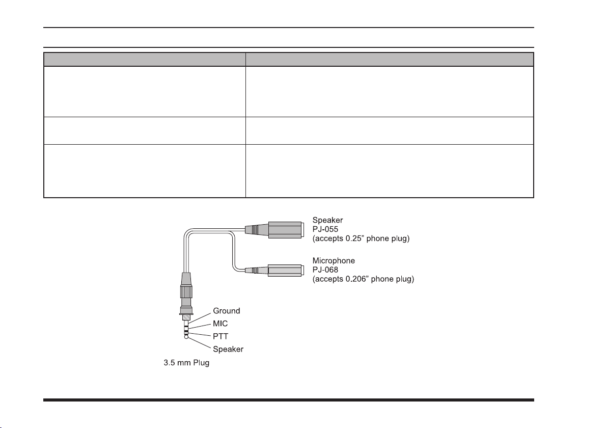
FTA-310 OperATing MAnuAl
trouBlesHootIng
QuestIon
When connecting the
tween the radio and a headset, the red transmit
LED on the radio turns on and the radio cannot be
operated.
Can I purchase the optional PTT Switch from
Yaesu?
Will my headset work with this radio?
headset cable be-
CT-96
answer
This happens when the connector on the
pushed into the
The jack must be screwed into the
tacts within the radio.
Contact your Aviation dealer for details on purchasing an aftermarket
Push-To-Talk switch.
The
CT-96
to be concretely sure check with the headset manufacturer providing the
wiring shown below. Please conrm the connections and connector sizes
are correct.
Headset Note:
Earphone (speaker) Impedance: 8 or above
MIC Impedance: 150 ±20%
PTT pressed: Ground
PTT not pressed: Open
MIC/EAR
headset cable is made to operate with most headsets; however
jack.
MIC/EAR
headset cable is simply
CT-96
jack to make proper con-
56
Page 59
FTA-310 OperATing MAnuAl
cH no.
1
2
3
4
5
6
7
8
9
10
11
12
13
14
15
16
17
18
19
20
21
22
23
24
25
26
27
28
29
30
BooK memory cHannel lIst
alpHa tag
AIR-AIR
AIR-AIR
ARINC 01
ARINC 02
ARINC 03
ARINC 04
ARINC 05
ARINC 06
ARINC 07
ARINC 08
ARINC 09
ARINC 10
ARINC 11
ARINC 12
ARINC 13
ARINC 14
ARINC 15
ARINC 16
ARINC 17
ARINC 18
ARINC 19
ARINC 20
ARINC 21
ARINC 22
ARTCC 01
ARTCC 02
ARTCC 03
ARTCC 04
ARTCC 05
ARTCC 06
Frequency (mHz
123.450
131.800
136.500
136.525
136.550
136.575
136.600
136.625
136.650
136.675
136.700
136.725
136.750
136.775
136.800
136.825
136.850
136.875
136.900
136.925
136.950
136.925
136.950
136.975
136.000
136.025
136.050
136.075
136.125
136.150
)
Unofcial Air-Air
Air to Air
Aeronautical Enroute Channel
Aeronautical Enroute Channel
Aeronautical Enroute Channel
Aeronautical Enroute Channel
Aeronautical Enroute Channel
Aeronautical Enroute Channel
Aeronautical Enroute Channel
Aeronautical Enroute Channel
Aeronautical Enroute Channel
Aeronautical Enroute Channel
Aeronautical Enroute Channel
Aeronautical Enroute Channel
Aeronautical Enroute Channel
Aeronautical Enroute Channel
Aeronautical Enroute Channel
Aeronautical Enroute Channel
Aeronautical Enroute Channel
Aeronautical Enroute Channel
Aeronautical Enroute Channel
Aeronautical Enroute Channel
Aeronautical Enroute Channel
Aeronautical Enroute Channel
Air Trafc Control General Use
Air Trafc Control General Use
Air Trafc Control General Use
Air Trafc Control General Use
Air Trafc Control General Use
Air Trafc Control General Use
note
(
usa versIon: Factory deFault
cH no.
31
32
33
34
35
36
37
38
39
40
41
42
43
44
45
46
47
48
49
50
51
52
53
54
55
56
57
58
59
-
alpHa tag
ARTCC 07
ARTCC 08
ARTCC 09
ARTCC 10
ARTCC 11
ARTCC 12
ARTCC 13
ARTCC 14
ARTCC 15
FAS
FOREST
FSS
HLC AIR
INTL G/C
INTL NY
INTL SF
MIL TWR
RESCUE
RESCUE T
SCHOOL 1
SCHOOL 2
UNICOM 1
UNICOM 2
UNICOM 3
UNICOM 4
UNICOM 5
UNICOM 6
UNICOM 7
UNICOM 8
---
Frequency (mHz
136.175
136.225
136.250
136.300
136.325
136.350
136.400
136.425
136.450
122.000
122.925
123.600
123.025
130.700
129.900
131.950
126.200
123.100
122.900
123.300
123.500
122.700
122.725
122.750
122.800
122.950
123.000
123.050
123.075
---
)
)
Air Trafc Control General Use
Air Trafc Control General Use
Air Trafc Control General Use
Air Trafc Control General Use
Air Trafc Control General Use
Air Trafc Control General Use
Air Trafc Control General Use
Air Trafc Control General Use
Air Trafc Control General Use
Enroute Flight Advisory Service
Forest Management
Flight Service Station
Helicopter Air to Air
International Gulf/Caribbean
International New York
International San Francisco
Military Tower
Search and Rescue
Training Search and Rescue
Flight Schools
Flight Schools
Unicom-Airports without towers
Unicom-Private Airports
Unicom-Air to Air
Unicom-Airports without towers
Unicom-Airports with towers
Unicom-Airports without towers
Unicom-Heliports
Unicom-Heliports
note
- - -
57
Page 60
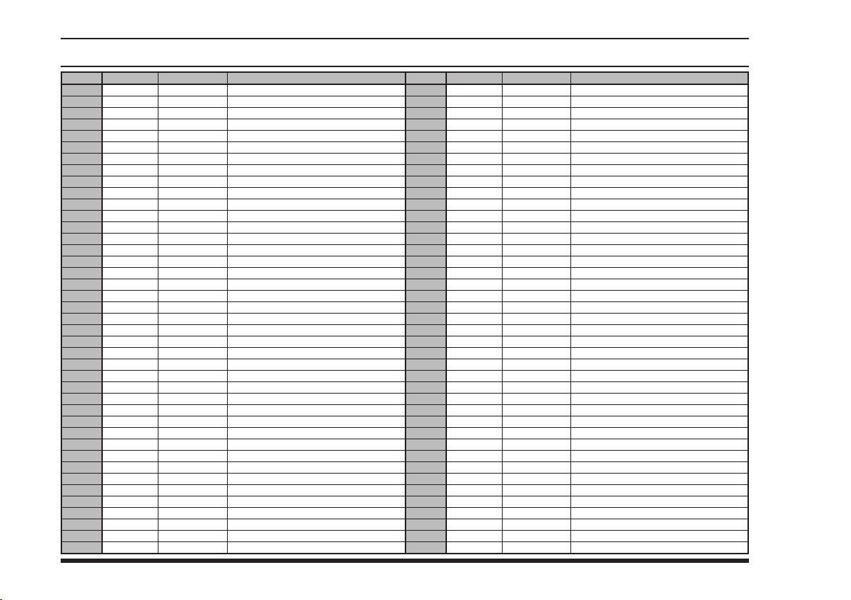
FTA-310 OperATing MAnuAl
58
cH no.
1
2
3
4
5
6
7
8
9
10
11
12
13
14
15
16
17
18
19
20
21
22
23
24
25
26
27
28
29
30
31
32
33
34
35
36
37
38
39
40
41
alpHa tag
AMS VMT
ANK VMT
ATH VMT
BCN VMT
BEG VMT
BER VMT
BOO VMT
BOD1 VMT
BOD2 VMT
BRU VMT
BUH VMT
BUD VMT
CPH VMT
DUB VMT
FRA1 VMT
FRA2 VMT
GVA VMT
HEL VMT
INN VMT
IST VMT
LPA VMT
LIS VMT
LON1 VMT
LON2 VMT
LON3 VMT
MAD VMT
MRS1 VMT
MRS2 VMT
MIL VMT
MOW VMT
OSL VMT
PAR1 VMT
PAR2 VMT
PRG VMT
ROM VMT
LED VMT
SOF VMT
STO VMT
SDL VMT
TLV VMT
VIE VMT
BooK memory cHannel lIst
Frequency (mHz
126.200
127.000
127.800
127.600
126.400
128.400
124.250
126.400
127.000
127.800
126.800
127.400
127.000
127.000
127.600
135.775
126.800
128.400
130.475
127.400
126.200
126.400
135.375
128.600
126.600
126.200
127.400
128.600
126.600
127.875
128.600
126.000
125.150
128.600
126.000
125.875
126.600
127.600
127.800
126.800
126.000
)
AMSTERDAM MET BROADCAST
ANKARA (ESENBOGA MET BROADCAST)
ATHENS(ATHINAI VOLMET)
BARCELONA
BELGRADE VOLMET
BERLIN VOLMET
BODO VOLMET
BORDEAUX RADIO
BORDEAUX RADIO
BRUSSELS
BUCHAREST VOLMET
BUDAPEST VOLMET
COPENHAGEN VOLMET
DUBLIN VOLMET
FRANKFURT 1 VOLMET
FRANKFURT 2 VOLMET
GENEVA MET BROADCAST
HELSINKI VOLMET
INNSBRUCK (NATIONAL VOLMET INNSBRUCK AUSTRIA)
ISTANBUL(ATATURK MET BROADCAST)
LAS PALMAS VOLMET
LISBON(LISBOA VOLMET)
LONDON VOLMET(MAIN)
LONDON VOLMET(SOUTH)
LONDON VOLMET(NORTH)
MADRID VOLMET
MARSEILLE RADIO
MARSEILLE RADIO
MILAN(MILANO VOLMET)
MOSCOW VOLMET
OSLO VOLMET
PARIS RADIO
PARIS RADIO
PRAGUE VOLMET
ROME VOLMET
ST. PETERSBURG VOLMET
SOFIA VOLMET
STOCKHOLM VOLMET
SUNDSVALL VOLMET
TEL AVIV(BEN GURION RADIO)
VIENNA(VOLMET WIEN AUSTRIA)
note
cH no.
(
eXp versIon: Factory deFault
42
43
50
51
52
53
54
55
56
57
58
59
60
61
62
63
64
65
66
67
68
69
70
71
72
73
74
75
76
77
78
79
80
81
82
83
84
85
86
87
88
alpHa tag
WAW VMT
ZRH VMT
AMS ATIS
AMS ATIS
ESB ATIS
ATH ATIS
BCN ATIS
BEG ATIS
TXL ATIS
BOO ATIS
BOD ATIS
BRU ATIS
OTP ATIS
BUD ATIS
FRA ATIS
GVA ATIS
CPH ATIS
CPH ATIS
DUB ATIS
LGW ATIS
LHR ATIS
HEL ATIS
INN ATIS
IST ATIS
FBU ATIS
CDG ATIS
ORY ATIS
PRG ATIS
FCO ATIS
MAD ATIS
MRS ATIS
SVO ATIS
VKO ATIS
LED ATIS
SOF ATIS
ARN ATIS
ARN ATIS
TLV ATIS
VIE ATIS
WAW ATIS
ZRH ATIS
Frequency (mHz
127.600
127.200
132.975
122.200
123.600
123.400
118.650
119.500
125.900
123.900
131.150
132.475
118.500
124.650
118.025
135.575
122.750
122.850
124.525
136.525
123.900
135.075
126.025
128.200
126.125
128.000
126.500
122.150
121.700
118.250
125.350
126.375
125.875
127.400
124.050
119.000
121.625
132.500
122.950
120.450
128.525
)
WARSAW VOLMET
ZURICH MET
AMSTERDAM(Schiphol)
AMSTERDAM(Schiphol)
ANKARA(Esenboga)
ATHENS
BARCELONA
BELGRADE
BERLIN(Tegel)
BODO
BORDEAUX(Merignac)
BRUSSELS(National)
BUCHAREST(Otopeni)
BUDAPEST(Ferihegy)
FRANKFURT(Main)
GENEVA(Cointrin)
COPENHAGEN(Kastrup)
COPENHAGEN(Kastrup)
DUBLIN
LONDON(Gatwick)
LONDON(Heathrow)
HELSINKI(Vantaa)
INNSBRUCK
ISTANBUL(Ataturk)
OSLO(Fornebu)
PARIS(Charles de Gaulle)
PARIS(Orly)
PRAGUE(Ruzyne)
ROME(Fiumicino)
MADRID(Barajas)
MARSEILLE(Provence)
MOSCOW(Sheremetievo)
MOSCOW(Vnukovo)
ST. PETERBURG(Pulkovo)
SOFIA
STOCKHOLM(Arlanda)
STOCKHOLM(Arlanda)
TEL AVIV(Ben Gurion Intl)
VIENNA(Schwechat)
WARSAW(Okecie)
ZURICH
)
note
Page 61
FTA-310 OperATing MAnuAl
]
or
key
[ ( )]
key, then press
4/CDI
[
knob several times to select -MR-
Tag Channels (Memory Display)
1. Press downward on the VOLUME
(Cut Here)
Quick Reference
( )]
[
the key to change Memory
mode.
2. Press the
display.
Mode Selection
Press downward on the VOLUME
knob to switch the operating mode
YAESU MUSEN CO., LTD.
Quick Reference Card
Memory Programming
Select the desired frequency in the
VFO mode, or recall the “Book ”
key, Then press the
]
F
[
key.
( )]
between the VFO mode, Memory
mode, Book mode and WX mode.
Lock Function
Memory channel or Weather channel
to be stored in the Main Memory.
Press the
[
key.
)]
SPL-W
(
MW
[
1. P r e s s a n d h o l d i n t h e
M W
[
to select the de s i r e d memor y
channel number for storage.
2. Rotate the DIAL selector knob
3. P re ss a n d ho l d in th e
VOR Navigation
key.
)]
SPL-W
(
select any of the character.
4. Rotate the DIAL selector knob to
5. When the desired first character
1. Select the VOR station frequency.
appears, Press downward on the
key, then press
]
F
[
key to change ag.
for 2 seconds, course indicator
di splay to toggle betw een the
sma ll d ispl ay a nd t he l arge r
display area.
3. Press and hold in the
2. Press
key for
)]
SPL-W
(
MW
[
VOLUME knob momentarily to
move on to the next character.
(eig h t ch a racte r s ma x im um),
press the
2 seconds to save all data for the
channel and exit.
6. After entering the entire name
key, then press
]
F
[
key to select CDI mode.
4. Press
59
Page 62

seconds to save all data for the
press the
8. After entering the entire name
(eig h t ch a racte r s ma x im um),
9. Turn the radio off, then turn the
channel.
radio back on again to begin
normal operation.
on to the next character.
momentarily to select it and move
7. P r e s s t h e V O L U M E k n o b
to select any of the 48 available
characters.
to use the DIAL selector knob
size.
6. To label a memory with an alpha/
numeric name, the next step is
4. Press and hold in the
for 2 sec o nd s to ch a nge t h e
“COURSE INDICATOR” display
[
( )]
key
and hold in the
for 2 seconds to save the entry
and exit.
The couse indicator shows “OFF”
3. Press
key to select CDI mode.
wh e n the VOR signal ca n not
received.
To attach an alpha/numeric name
(label) to the memory, proceed
to the next step; otherwise press
MW
“FROM” flag when flying away
from the VOR station.
[
F
]
key, then press
[
4/CDI
]
5. P r e s s a n d h o l d i n t h e
to select the de s i r e d memor y
channel number for storage.
[
2. Select the “TO” flag when flying
VOR station.
to the VOR station or select the
3. P r e s s a n d h o l d i n t h e
4. Rotate the DIAL selector knob
[
MW
Fly to a VOR station
1. Sel ect a VOR st ation on yo u r
aeronautical chart and turn the
DIAL se l e ct or knob (or ente r
the frequency directly with the
keypad) to the frequency of the
Field Programming Mode
2. Select the desired frequency to
be stored in the Book Memory.
1. Press and hold in both the PTT
switch and VOLUME knob, while
turning the radio on.
60
[
MW
(
SPL-W
)]
key for 2
[
MW
(
SPL-W
)]
key
(
SPL-W
)]
key for 2 seconds.
(
SPL-W
)]
key for 2 seconds.
FTA-310 OperATing MAnuAl
Page 63

Part 15.21: Changes or modications to this device
not expressly approved by YAESU MUSEN could
void the user’s authorization to operate this device.
Page 64

YAESU MUSEN CO., LTD.
Tennozu Parkside Building
2-5-8 Higashi-Shinagawa, Shinagawa-ku, Tokyo 140-0002 Japan
YAESU USA
6125 Phyllis Drive, Cypress, CA 90630, U.S.A.
YAESU UK
Unit 12, Sun Valley Business Park, Winnall Close
Winchester, Hampshire, SO23 0LB, U.K.
YAESU HK
Unit 2002, 20/F, 9 Chong Yip Street,
Kwun Tong, Kowloon, Hong Kong
1211M-AY
Copyright 2012
YAESU MUSEN CO., LTD.
All rights reserved.
No portion of this manual may be
reproduced without the permission of
YAESU MUSEN CO., LTD.
Printed in Japan
EC057N151
 Loading...