

Page 1
OPERATING
Y
MANUAL
FT-712RH
AESU MUSEN CO.,
LTD. C.P.O. BOX 1500
TOKYO, JAPAN
Page 2

CONTENTS
y
p
SUPPLIED ACCESSORIES . .
2Memor
Storage21
Memory Recall 22
OPTIONS . . . . . . . . . .
2 Hiding/Erasing Memories 22
Call Channel Memory 23
SPECIFICATIONS . . . . . .
3Scanning 23
Memory Skip Scanning 24
CONTROLS & CONNECTORS
4 Programmable Memory
FRONT PANEL 4 Scanning (PMS) 24
REAR PANEL 7 Priority Monitoring 25
Tone Squelch Operation 26
INSTALLATION . . . . . . .
Antenna Considerations 8
Mobile Installation 8
8
DVS-1 DIGITAL VOICE
SYSTEM . . . . . . . .
Mobile Power Connections 10 Voice System Display 28
External Accessories 11 Segmentation Codes 30
Base Station Installation 12 Recording 30
Packet TNC Interconnections 12 On-The-Air Recording &
DVS-1 Digital Voice System Playback 32
Installation 13 Remote Station Recording
FTS-12 Tone Squelch Unit & Playback 32
Installation 15 Locking Segments 34
Memory Cloning 16
Modification for Packet Radio
17
Private Station ID Code 35
CAT System External Compu-
ter Control . . . . . . .
OPERATION . . . . . . . .
18
Preliminary Operating Infor
mation 18
In Case of Problems . . . . .
Squelch Setup 18
Frequency/Step Selection 19
Transmitting 20
eater Splits 20
Re
27
37
40
Page 3

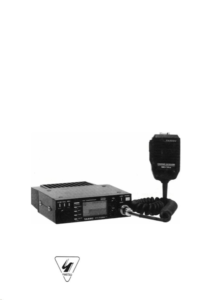
YAESU FT-712RH COMPACT 70cm FM MOBILE
TRANSCEIVER
The FT-712RH is a compact, full-featured frequency synthesized FM mobile/base
transceiver providing selectable power output of either 3 or 35 watts on the 70cm
amateur band. Unique features include the optional DVS-1 Digital Voice System,
which provides local and remote digital voice recording and playback when
installed in the FT-712RH.
Inside the FT-712RH, surface-mount components provide high reliability and
performance, while modular circuit construction makes servicing easy. An allnew compartmentalized die-cast chassis provides superb rf isolation and
incredible overall ruggedness. A large liquid crystal display includes a bargraph
PO/S-meter. Ambient light is sensed to automatically control the brightness of
the display back-lighting and pilot lamps, dimming the display in dark
environments.
Operating features include memory selection and tuning in 5, 10, 12.5, 15, 20 and
25 kHz selectable steps; The channel memory system includes 19 general purpose
memories, a one-touch recall CALL channel memory and two subband limit
memories (for programmable subband scanning); one-touch repeater reverse;
band and selected memory scanning with auto-resume after carrier-drop or 5second pause, and priority channel monitoring. Memory hiding and scan-skip are
easily settable.
Twenty of the memories store either programmable repeater shift or independent
transmit and receive frequencies. When the optional FTS-12 Tone Squelch unit is
installed, any of 37 standard CTCSS (subaudible) tone frequencies can be
displayed, selected and programmed into any memory channel for either silent
monitoring or encode-only operation.
The microphone jack includes signals for CAT System control from an external
personal computer, and memory cloning to/from other FT-712RHs. A 1750 Hz
burst tone generator is built-in and can be activated from the MH-14A8
Speaker/Mic. DTMF keypad microphone options include the MH-15C8 and the
MH-15D8 with its own auto-dial DTMF memories. If the burst tone is not
needed, an internal jumper can be set to allow packet radio tnc interfacing via the
microphone jack.
- 1 -
Page 4

Along with one microphone, the MMB-37 Reversible Mobile Bracket is supplied
)
)
with the transceiver. For base station installations, the FP-700 AC Power
Supply/External Speaker is optionally available.
Please read this manual before installing or operating the FT-712RH.
SUPPLIED ACCESSORIES
MMB-37 Mobile Mounting Bracket 136000056
Power Supply Cable T9015615 with two 15A fuses, 2.8m One of the
microphones listed below.
OPTIONS
Model
DVS-1 Digital Voice Memory Unit 133000567
FTS-12 Tone Squelch Unit 133000488
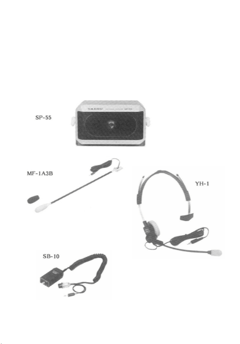
SP-55 External Speaker
MH-14A8 Hand Speaker/Mic w/Burst Button 131000051
MH-14B8 Hand Speaker/Mic 131000052
MH-14138 Standard Hand Mic 131000067
MH-15C8 Hand Speaker/Mic w/DTMF keypad 131000060
MH-15138 Hand Mic w/DTMF Autodialler Memory 131000061
MF-1A3B Boom Microphone with flexible arm
YH-1 Headset (w/microphone)
SB-10 PTT Switch Unit for MF-1A3B or YH-l
Order Code
MODEL CHART
Version Freq. range (MHz
A 430 - 450 ±5
B 430 - 440 ±7.6**
C 430 - 440 ±1.6**
X 430 - 440 ±5
* Default - freely programmable by operator
** Burst tone activated by MH-14A8 Microphone.
R tr. Shifter* (MHz
-2-
Page 5

SPECIFICATINS
GENERAL RECEIVER
Frequency range: Circuit type:
see Model Chart Double-conversion superhet
Channel steps Intermediate frequencies:
5/10/12.5/20/25 kHz 45 MHz & 455 kHz
Standard repeater shift: Sensitivity (for 12dB SINAD):
see Model Chart better than 0.18uV
Mode of emission: Image ratio:
G3E better than 65dB
Antenna impedance: Selectivity (-6/-60dB)
50 ohms, unbalanced 12/30 kHz
Supply voltage: Audio Output (for 5% THD):
13.8 VDC ±10%, neg. Ground at least 1.5W into 8 ohms
Supply current:
Transmit 35W: 10A TRANSMITTER
Receive: 500mA
Standby: 300mA RF output power (50 ohms):
3 watts and 35 watts
Operating temp. range:
-20 to +60 °C Modulation method:
Variable reactance
Frequency accuracy:
±5ppm (-5° to +50°C) Maximum deviation:
±5 kHz
Case size (WHD):
140 x 40 x 160mm Spurious emissions:
Weight:
Approx. 1.25 kg Microphone impedance:
Specification subject to change without notice.
at least 60 dB below carrier
2 kilohms
-3-
Page 6
CONTROLS & CONNECTORS
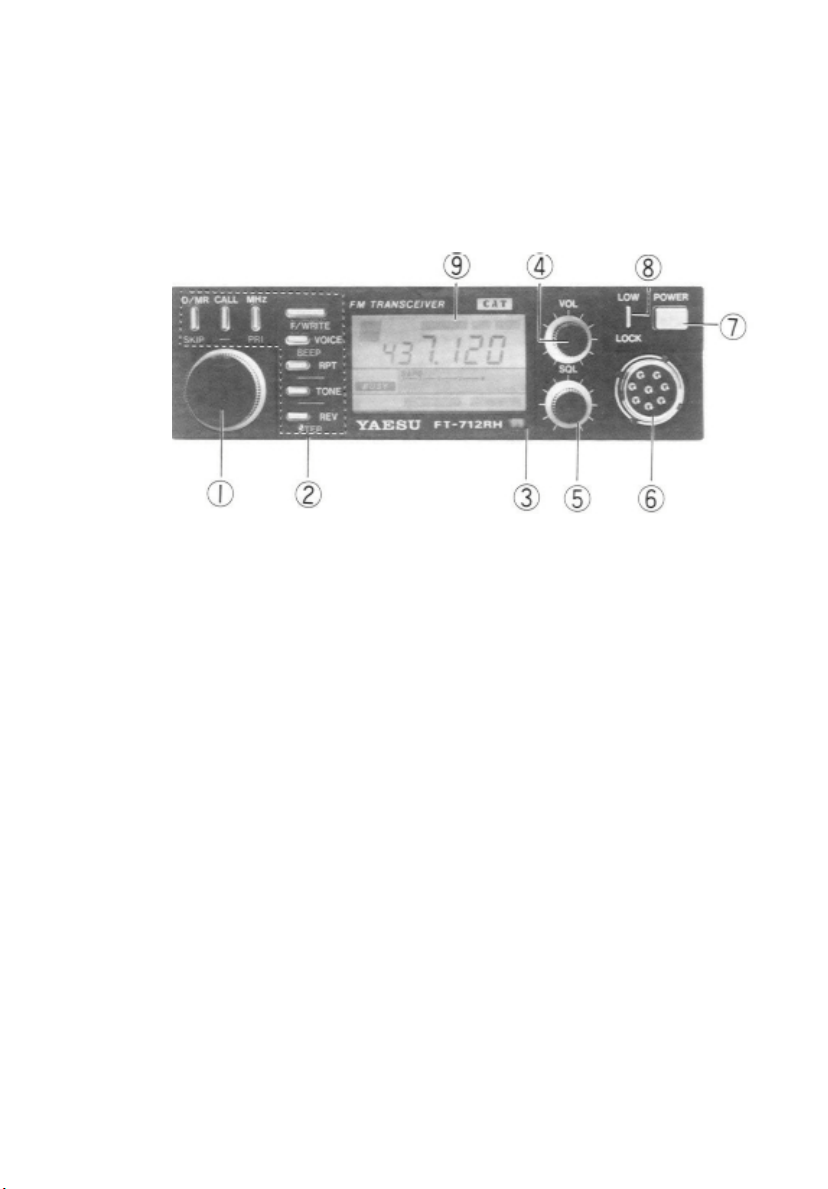
FRONT PANEL
(1) Selector Knob
This 24-position detented rotary switch is used for tuning as well as a wide variety
of function selections. The DWN and UP keys on the microphone duplicate the
functions of this knob.
(2) Push Button Switches
These push buttons select the various operating features. One or more beeps will
sound if the resulting command is accepted (beep notes are shown on page 33). The
white labels above or to the right of the buttons indicate their primary functions,
while the blue labels below the buttons indicate alternate functions, activated by
pressing the F/WRITE button momentarily first, and then the other button within
five seconds.
For descriptive purposes in this manual, alternate button functions are referenced
by the blue label, with "[F]+" in front of it to remind you to press F/WRITE first.
For example, "[F)+BEEP" indicates that you should press the F/WRITE button
followed by the VOICE/BEEP button (within five seconds). All button functions
are described in detail in the "Operation" section, and summarized in the
Operator's Quick Reference Charts.
- 4 -
Page 7

(3) Auto Dimmer Sensor
Behind the glass is a photosensor which detects the level of ambient light,
causing the display lamps to be automatically dimmed in the dark.
(4) VOL Control
This control adjust the volume of the receiver audio.
(5) SQL Control
This control sets the threshold level at which received signals (or noise) open the
squelch. For maximum squelch sensitivity set this control from counterclockwise
just to the point where noise is silenced (and the BUSY indicator on the display
is off) when the channel is clear.
(6) MIC Jack
This 8-pin jack accepts microphone input and scanning control from the
microphone and/or control signals from an external computer. Memory cloning
can be performed with another transceiver through this jack, and an internal
modification also allows packet radio tnc connection here. Pinout is shown on
the next page.
(7) POWER Switch
This two-position push button turns the transceiver on and off.
(8) LOW/LOCK Button
Normally, this button toggles between high and low transmitter power output.
When low power is selected, two low-pitched beeps sound, and "LOW" appears
at the lower right corner of the display. Two highpitched beeps sound when high
power is selected.
If the F/WRITE button is pressed just before pressing the LOW/LOCK button,
transmitter power is not changed, but rather low/high beeps sound, and "LOCK"
appears in reverse letters at the lower left corner of the display, indicating that
the selector knob and all other
- 5 -
Page 8
buttons are now disabled. Pressing [F]+LOCK again sounds high/low beeps as
the lock condition is released.
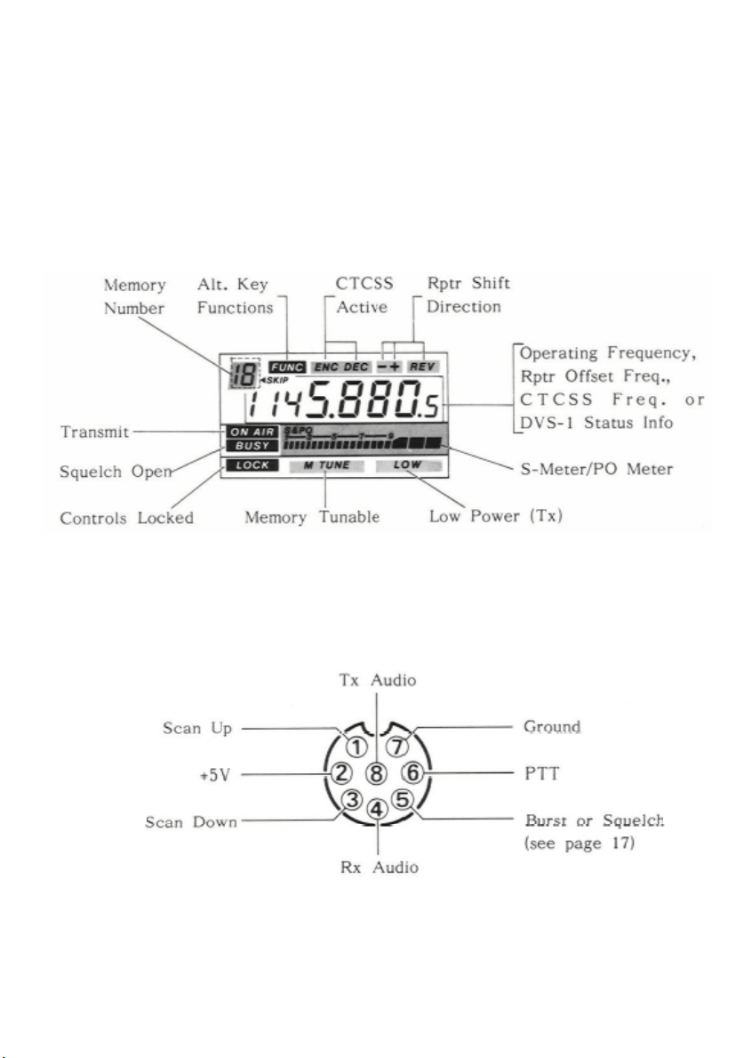
(9) Display
The display segments are follows. The meaning of each is described elsewhere in
this manual
MIC Jack Pinout
- 6 -
Page 9
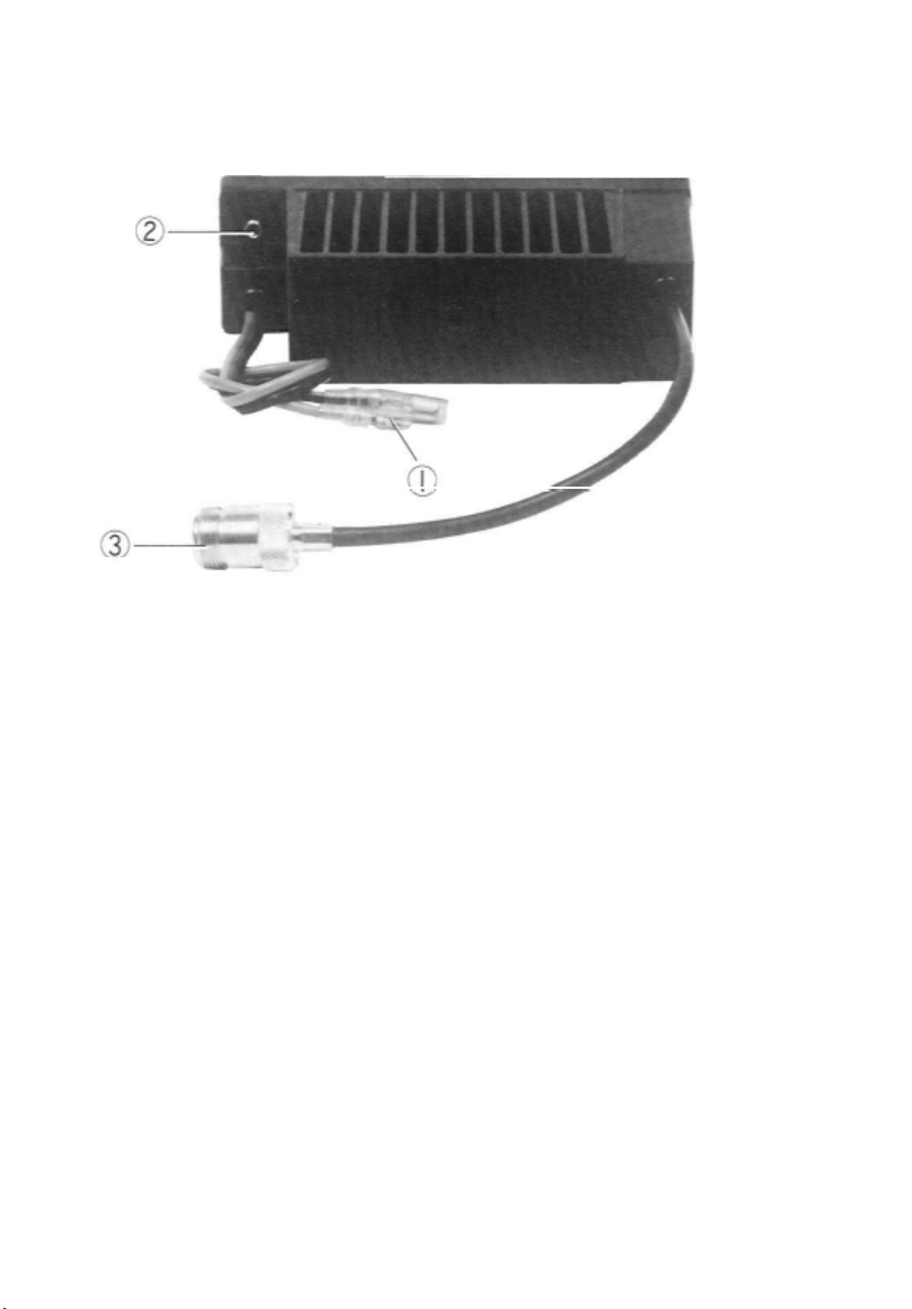
REAR PANEL
(1) 13.8VDC Cable Pigtail
This is the power supply connection for the transceiver. Use the fused DC Cable
supplied with the transceiver to make connection between this pigtail and the car
battery or other DC power supply capable of at least 10 Amperes (continuous). Make
certain that the red lead connects to the positive side of the supply.
(2) EXT SP (External Speaker) Jack
This 2-contact mini phone jack accepts a 4- to 16-ohm external speaker such as the
Yaesu SP-3, SP-4 or SP-55. When a plug is inserted into this jack the internal
speaker is disabled.
(3) ANT (Antenna) Jack
Connect a 70cm antenna to this type-N socket using 50-ohm coaxial cable and a
type-N plug. Make sure the antenna is designed specifically for use at the operating
frequency.
-7-
Page 10

INSTALLATION
Antenna Considerations
The FT-712RH is designed for use with an antenna having an impedance near 50
ohms at the operating frequency. For optimum performance use a high-quality,
carefully designed antenna. The antenna should be connected at all times when
power is on, to avoid damage that can otherwise result if transmission occurs
accidentally when no antenna is connected.
Another important consideration is the feedline. For optimum performance use
the shortest possible length of the best quality coaxial cable available, and be
sure to use a properly matching plug (type-N) for the jack on the transceiver.
Mobile Installation
The FT-712RH must only be installed in cars having a negative ground electrical
system. The transceiver should be located where the display, controls and
microphone are easily accessible, and should be securely affixed using the
supplied MMB-37 mobile mounting bracket. The transceiver may be installed in
any position without adversely affecting its performance, but it should not be
mounted near a heater vent or where it could interfere with safe operation of the
vehicle. Make sure that plenty of space is provided at the rear of the transceiver
so that air can flow freely around the heatsink. Refer to the diagrams on the
facing page for installation of the MMB-37.
(1) Using the mounting bracket as a template, locate the mounting holes after
determining the mounting location with sufficient clearance for the
transceiver. Use a 4.8mm (3/16") bit to drill the holes. Secure the bracket
with the supplied screws, washers and nuts (Figure 1).
(2) Screw the two mounting clips to the sides of the transceiver using the small
hex bolts and washers supplied (Figure 2).
-8-
Page 11
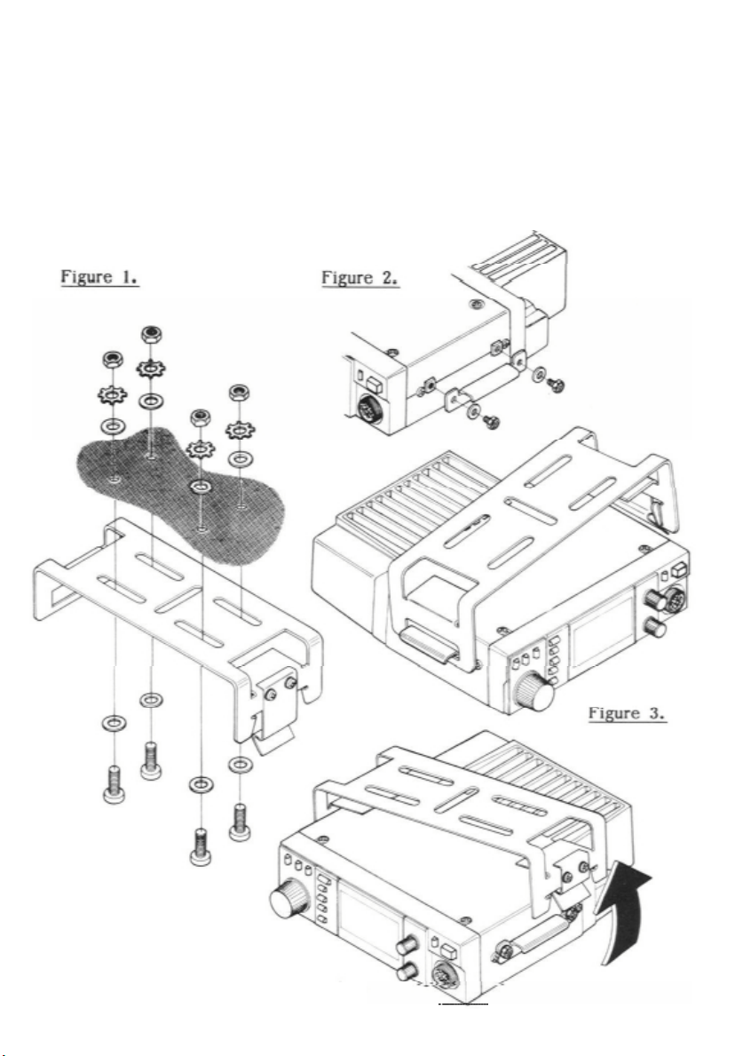
To install the transceiver, position the transceiver in the bracket so that the clip
on the left side fits into the slot in the left side of the bracket e 31, then push
the right side of the transceiver upwards until it latches.
To remove the transceiver place your hand underneath it and pull the latch on
the right side of the bracket outward until the right side of the transceiver drops
free.
-9-
Page 12

Mobile Power Connections
p
Before connecting the power cable the maximum battery charging voltage should be
checked to ensure that it remains below 15V when the engine is run fast. If more
than 15V, the voltage regulator of the car should be adjusted before connecting the
transceiver.
Power connections should be made directly to the automobile battery using the
supplied cable with 15A in-line fuses. Connection to the cigarette lighter or other
accessory circuit may cause the fuse to blow in that circuit. Connecting the supplied
DC power cable to the battery independently of the rest of the automobile electrical
system will minimize possible ignition noise pickup and excessive supply voltage
during transmission, while allowing operation with the ignition off.
dro
Do not connect any power to the transceiver except via the supplied fused cable, and
do not attempt to defeat or bypass the fuses - they are their to protect you and the
equipment.
Connect the RED lead of the power cable to the POSITIVE (+) battery
terminal, and the BLACK lead to the NEGATIVE (-) terminal. If it is necessary to
extend the power cable, use #14 AWG or larger insulated, stranded copper wire, and
in all cases use the minimum power cable length practicable to keep voltage drop
minimal.
WARNING
NEVER APPLY AC POWER TO THE REAR PANEL POWER JACK
OF THE TRANSCEIVER. NEVER CONNECT DC VOLTAGE OF
MORE THAN 15 VOLTS TO THE POWER JACK. ALWAYS REPLACE FUSES WITH 15A RATING. FAILURE TO OBSERVE THESE
PRECAUTIONS WILL VOID THE WARRANTY.
- 10 -
Page 13
External Accessories
The SP-3, SP-4 and SP-55 External Speakers are optional accessories which allow
the source of audio from the transceiver to be repositioned for optimum hearing.
Especially practical for the noisy mobile environment, each includes its own
swivel-type mounting bracket, and is available from your Yaesu dealer. Also
available to enhance safety and mobile operating convenience are the YH-I Headset
with miniature boom microphone, and the full size MF-1A3B boom microphone
with flexible arm (both of which use the SB-10 PTT switch).
- 11 -
Page 14

Base Station Installation
A power supply capable of providing at least 10A continuously at 13.8VDC is
required for operation from the AC line, and an external speaker is recommended.
The FP-700 AC power supply is available from your Yaesu dealer for this purpose.
Use the fused DC power cable supplied with the transceiver for making power
connections, and connect the external speaker to the EXT SP jack on the rear panel.
Packet Radio TNC Interconnections
Most popular packet radio tncs can be connected to the MIC jack of the FT-712RH
as follows:
TNC Jack to Radio FT-712RH MIC Jack
Receiver Audio in pin 4 (8 ohms, de-emphasized)
Squelch Status in pin 5* (open=8V, closed=0V 1 mA)
PTT (gnd=tx) out pin 6
Transmit Audio out pin 8 (400 ohms, pre-emphasized)
Use shielded cable for the audio lines, and keep the interconnecting cable as short
as possible to avoid RF pickup.
* Requires modification as described on page 17.
- 12 -
Page 15

DVS-I Digital Voice System Installation
The DVS-I is a digital voice recording and playback system which allows you to
record either through the microphone or the receiver, and to play back selected
recorded messages through the speaker or transmitter. Remote-controlled recording
and playback is also provided by a built-in DTMF decoder. See the special section at
the end of this manual for complete details.
(1) Disconnect the power cable at the rear of the transceiver, place the transceiver
upside-down on the workbench, and remove the four screws on the bottom
cover. Loosen the two screws on each side, and then remove the bottom cover
(Figure 1).
(2) Lift the loudspeaker out of its holder, and then remove the three screws in the
arms of the holder, and lift it out of the chassis (Figure 2).
-13-
Page 16

(3) Connect the 8-pin plug from the DVS-I to 8-pin jack J2003 on the inside
of the front panel (the gray wire should be nearest the center). See Figure
3.
(4) Connect the 7-pin plug from the DVS-I to 7-pin jack J2004 on the inside
of the front panel (the brown wire should be nearest the center).
(5) Connect the 3-pin plug from the DVS-1 to jack J1003 in the right front
corner of the speaker compartment.
(6) Making sure that no wires are pinched, set the DVS-I in place, routing
the speaker wires out under the back of the DVS-I. Install the two
supplied screws through the tabs in the DVS-I: one in the left front
corner of the chassis, and one in the rear.
(7) Set the Voice Memory Backup switch in the left rear corner of the DVS-I
(Figure 4) to the ON position (toward the rear).
(8) If also installing the FTS-12, proceed to step 2 of the FTS-12 Installation.
-
- 14 -
Page 17

FTS-12 Tone Squelch Unit Installation
The FTS-12 provides either encode-only or encode/decode operation with 37
front panel selectable subaudible CTCSS tones, and is available for all versions
FT-712RH, from your local Yaesu dealer. See the "Operation" section for
functional details.
(1) Perform steps 1 and 2 of the DVS-I Installation Procedure.
(2) Remove the jumper plug from jack J1004 in the front left corner of the
speaker compartment (Fig. 5).
(3) Locate the unconnected brown 10-pin connector at the front of the speaker
compartment. Align the small tab on one side of this connector with the hole
in one side of the jack on the FTS-12, and mate these connectors (Fig. 6).
(4) Press the FTS-12 into the clip on the speaker holder (Fig. 7). The output tone
level (VRI on the FTS-12) is adjusted at the factory for the proper deviation,
so no adjustment is needed.
(5) Replace the speaker holder and its three screws, and replace the speaker in
the holder. Then replace the bottom cover and its four screws, and retighten
the two screws on each side.
- 175 -
Page 18

Figure 6. Figure 7.
Memory Cloning
All memory data stored in one transceiver can be moved to another by connecting
the MIC jacks together as indicated in the diagram below (cloning cable is NOT
available from Yaesu).
(1) Turn both transceivers off, and then press and hold the F/WRITE buttons
while turning the power switches on. The displays will be blinking.
(2) Press the REV button on the destination transceiver (the display will stop
blinking).
(3) Press the RPT button on the source transceiver. When the data transfer is
complete, the displays should return to normal. If "Err" is displayed, turn
both transceivers off and try again.
(4) Turn both transceivers off and remove the cloning cable.
-16-
Page 19

Modification for Packet Radio
As supplied from the factory, pin 5 of the MIC jack is wired through solder bridge
jumper no. 16 on the Control Unit to allow tone burst activation via the BURST
button on the MH-14A8 microphone. For packet radio operation jumper 16 must be
removed, disabling BURST control, and jumper 15 installed to provide output of
the squelch BUSY line for packet radio tries.
(1) Remove the eight screws affixing the top and bottom covers, and the two
screws on each side. Remove the covers.
(2) Remove the ring nut and lockwasher around the MIC jack, and pull the
three knobs from the front panel.
(3) Without unclipping the plastic cover, grasp the front panel on the top and
bottom edges, and carefully slide it forward just enough to expose the
corner of the Control Unit pcb nearest the MIC jack.
(4) Using a fine-tipped soldering iron and solder wick or a solder sucker,
remove the solder bridge from BURST jumper pad 16, and then add
solder to bridge BUSY pad 15.
(5) Press the front panel assembly gently back into place (so that the holes in
each side are aligned with those in the chassis). Replace the ring nut and
washer over the MIC jack, and the knobs. Replace the top and bottom
covers and their eight screws, and the four screws in the sides.
17
Page 20

OPERATION
This chapter describes the various transceiver functions in detail. After studying
these descriptions, keep the FT-712RH Operator's Quick Reference Charts handy
in case you need to refresh your memory.
Preliminary Operating Information
Before operating the transceiver, recheck power supply and antenna connections.
Never operate the transceiver without an antenna. Also, please read the chapter on
Controls & Connectors, if you have not already, to familiarize yourself with the
functions of the controls. Note especially the description on page 4 of the
terminology used in this chapter when referring to the buttons.
When the buttons are pressed during reception, one or more beeps will sound if the
command is accepted. Except for certain special cases mentioned later, the buttons
are disabled during transmission.
If you have trouble getting the transceiver to work as described, see 'In Case of
Problems' on page 40.
Squelch Setup
Before turning on the transceiver for the first time, set the VOL and SQL controls
fully counterclockwise. Now press the POWER button and adjust the VOL control
for a_ comfortable volume on the noise or received signal. "BUSY" should be
displayed in reverse letters to the left of the S&PO meter scale. If a signal is
present, rotate the selector knob until a frequency is found where only noise is
heard.
Turn the SQL knob clockwise just to the point where the noise is silenced and
"BUSY" disappears (if the SQL is set further clockwise, sensitivity to weak signals
is reduced). Whenever a signal reaches the receiver that is strong enough to open
the squelch, "BUSY" will be displayed.
Bargraph segments appear in the S&PO box below the frequency on the display
while receiving, indicating received signal strength. This indication
- 18 -
Page 21

is not affected by the squelch setting, so even squelched signals will have some
indication. If you notice more than one or two bargraph segments appearing while
the squelch is still closed, try reducing the squelch control setting (if you want to
hear weak signals).
Frequency & Step Selection
To select the MHz range in which you wish to operate, press the MHz button (if
nothing happens, see the LOCK description on page 5). Digits to the right of the 1MHz digit are cleared from the display for five seconds, during which you can use
the selector knob or the microphone UP/DWN keys to change the MHz range. Try
this, and note the beeps when using the microphone keys: when moving up, and
when moving down. When done, press MHz again, or wait five seconds.
To tune your operating frequency, the transceiver must be in what we call the Dial
mode (as opposed to the Memory mode, described later). If no Memory number is
present in the shaded box in the upper left-hand corner of the display, the Dial
mode is selected. Otherwise, press the D/MR button to change to the Dial mode.
You can use the selector knob or the microphone UP and DWN keys to select your
operating frequency. However, if you press and hold the UP or DWN key for more
than 2-second scanning will start. This is described later, so for now, just press the
microphone key again to stop (if you have to).
Tuning steps are factory preset to 12.5 or 25 kHz in all versions. To change to
another step size (5, 10, 12.5, 20 or 25 kHz) press [F]+REV, and use the selector
knob or microphone keys to select a different step (the step size is displayed at the
right). The small "S" or "P" at the left is the scan mode indicator, described later.
DISABLING THE BEEPER
You can toggle the musical beeper on and off by pressing [F]+BEEP.
While learning the features, we recommend you keep it on, as the
musical beeps aid the learning process.
- 19 -
Page 22

Transmitting
Press the LOW button to select low power output. When you wish to transmit, wait
until the channel is clear ("BUSY" not displayed), and squeeze the PTT switch on
the microphone. During transmission "ON AIR" is displayed in reverse letters to the
left of the S&PO box, and the bargraph shows relative transmitter power output.
Release the PTT switch to receive.
If more power is required, press the LOW button again. However, whenever
communication is possible with low power, keep the LOW button depressed to
minimize possible interference to other stations.
If using a version B or C (in Europe), press the BURST button on the MH-14A8
microphone, to transmit a 1750 Hz Burst Tone to access repeaters that require it.
Repeater Splits
The RPT button activates offset of the transmitting frequency from the receiving
frequency for plus or minus shift, as required for repeater operation.
To activate plus or minus split just press RPT: once for minus shift, or twice for plus
shift ("-" or "+" displayed above the 10 kHz frequency digit). When you press the
PTT switch to transmit (or the REV button to reverse transmit and receive
frequencies), the display will shift down or up by the programmed offset, if in band
(or else 'Err' is displayed). Pressing RPT again returns you to simplex operation.
The amount of repeater offset is programmed in the transceiver, and can be easily
reprogrammed as desired (default offsets are shown in the Model Chart on page 2).
If you have one or two repeaters in your area with non-standard splits, you can
program separate transmit and receive frequencies in memory as described later.
However, if most or all of the repeaters you want to work have a different split
offset from that programmed in the transceiver, you can reprogram the standard
offset (as controlled by the RPT button) instead.
- 220 -
Page 23

Press [F]+RPT to display the currently stored repeater offset. You can use the
same methods to change this offset as you use for general tuning (including MHz
steps), as described above under Frequency and Step Selection. When you have
the desired offset displayed, press RPT (only) to return to the operating
frequency display.
Memory Storage
The FT-712RH offers eighteen general purpose memories, numbered 1 through
18, and three special memories, labelled C, L and U. The general purpose
memories and the "C" (Call Channel memory) can each store separate receive and
transmit frequencies or repeater shift, and tone squelch data (if the optional FTS12 is installed). The L and U memories can store everything except separate
transmit frequencies, and are used for PMS operation, described later.
To store a frequency in memory:
(1) Select the desired frequency (and repeater split, if desired) in the Dial mode
as described above.
(2) Press and hold the F/WRITE key for 2-second (until the second beep sounds).
A Memory number appears blinking in the shaded box at the upper left corner
of the display.
(3) Within five seconds of step (2), use the selector knob or microphone
UP/DWN keys to select the desired Memory for storage. If you select one
that was already being used, it will be overwritten with new data in the next
step.
(4) Press F/WRITE again to store the displayed data into the selected Memory:
the Memory number will stop blinking for a second, and then disappear as
operation continues in the Dial mode.
When storing split-frequency memories you have the choice of either the
Repeater Split method, described previously, or of storing separate transmit and
receive frequencies. To store a separate transmit frequency, just store the receive
frequency as described above, and then tune to the desired transmit frequency,
press F/WRITE again for 2-second, and
- 21 -
Page 24

then hold the PTT switch while pressing F/WRITE once more (the transmitter is
not activated in this case). By either method the results will be the same in
operation, except that storing a separate transmit frequency applies only to one
memory, while the offset method applies to all (when the RPT button is pressed).
Memory Recall
To recall stored memories press D/MR to select the Memory mode (Memory
number is displayed), and then rotate the selector knob or press the up/down keys
to select the desired memory. Only prestored memories are displayed: empty
memories are skipped.
If you stored a memory for split-frequency operation by the offset method, "-" or
"+" will be displayed to remind you of the shift. If you stored a memory with a
separate transmit frequency, "-+" are displayed together to remind you of this. In
either case, you can press the REV button to check the transmit frequency without
actually transmitting (and press it again to return).
You can also retune a memory once it is recalled, by pressing the MHz button: "M
TUNE" appears at the bottom center of the display, and you can tune the
displayed memory frequency in the same ways as described before (including the
"MHz" tuning). If you retune and want to store the new memory settings (in the
current, or another memory), just follow steps (2) - (4) of the memory storage
procedure above: operation will be left on the memory.
If you don't want to save your changes to the memory, just press D/MR: once to
return to the original memory data, and again to leave the memories and return to
the Dial mode.
Hiding and Erasing Memories
As already mentioned, storing data in a memory automatically overwrites data that
was previously stored there. However, if you regularly move from one area to
another, you may not want to use the same number of memories all the time, or you
may wish to change your operating memories without having to rewrite them from
scratch. This can be done by
-22-
Page 25

masking certain memories so that they are completely hidden from operation, and
recalling them only when desired for operation.
To completely mask a memory, recall it and press F/WRITE for 2-second (until the
memory number blinks). Then press the REV/STEP button. This causes the display
to change to memory 1, and the previously-selected memory is no longer selectable
manually, or by scanning (as described later).
To unmask a hidden memory for operation, recall any memory and press F/WRITE
for 2-second. Then select the memory number to be restored, and press REV/STEP.
When you have hidden memories, be careful not to accidentally overwrite them.
Call Channel Memory
The call channel memory can be instantly recalled by pressing the CALL button.
"C" appears in the memory window at the upper left corner of the display.
As mentioned earlier, you can store the same kinds of data in the CALL channel as
-
the general purpose memories: just follow steps (1) through (3) of the memory
in
storage procedure, and then press the CALL button instead of F/WRITE in step (4),
while the "C" is blinking. Also, if storing a separate transmit frequency, press the
CALL button instead of F/WRITE while holding the PTT switch (in the final step).
Scanning
Before starting the scanner, make sure the SQL control is set to squelch off the
noise on a clear channel. Scanning is activated and deactivated by the UP or DWN
keys on the microphone. Just press and hold the key for more than 2-second to start
the scanner. If the transceiver is in the Dial mode, band scanning will result. If a
memory number is displayed, the transceiver is in the Memory mode, and only the
memories will be scanned.
-23-
Page 26

The scanner pauses whenever a signal is detected which is strong enough to open the
squelch, and the decimal point on the display blinks. You have a choice of two scanresume modes: either _Pause mode, in which the scanner pauses for as long as the
carrier keeps the squelch open, or the _Set duration mode, in which the scanner pauses
for five seconds and then resumes scanning whether or not the signal is still present.
To set the scan-resume mode, press [F]+REV/STEP. A small "P" or "S" at the left
indicates the current mode. Press the F/WRITE key to change it, or just press the
REV/STEP button alone to return to the frequency display.
You can stop the scanner manually by pressing the PTT, UP or DWN key on the
microphone, or the D/MR button.
Memory Skip Scanning
When you have some busy channels stored in memories you may wish to skip them
when scanning other memories, but still have them available for manual selection. You
can mark a memory to be skipped by pressing [F]+SKIP while the memory is recalled.
",< SKIP" will be displayed just to the right of the memory number box, and this
memory will be skipped during scanning (although you can still recall it manually).
To unmask a scan-skip memory, just repeat the same steps you took to mask it: select
the memory manually, and press [F]+SKIP.
Programmable Memory Scanning (PMS)
In addition to band and memory scanning, the FT-712RH can scan between two
frequencies of your choice stored in the special memories labelled "L" and "U":
(1) Store the lower edge of the desired scanning range in memory L, and the upper
edge in memory U.
(2) With either memory U or L recalled, press the MHz button. "M TUNE" will appear
at the bottom center of the display.
- 24 -
Page 27

You can now tune or scan as described previously, between the nearest multiples
ps)
of 100 kHz (xxx.000, xxx.100, xxx.200, etc.) below memory L and above memory
U.
To cancel PMS operation, stop scanning, if necessary (with the microphone keys
or D/MR), and press D/MR: once to return to regular memory operation, or twice
to return to Dial mode.
Priority Channel Monitoring
The Priority function allows automatic checking for activity on a memory every
five seconds while operating on the Dial or other memories. When a signal
appears on the priority memory while receiving, operation will automatically shift
to that memory, for as long as a carrier is received. If you transmit while paused
on the priority memory, priority monitoring is cancelled and operation stays on
the priority memory.
The squelch must first be preset, and the frequency to be monitored must be
stored in a memory (this MUST be memory 1 if you will be operating on other
memories during priority monitoring).
Press D/MR to operate on the Dial, or else select the memory you want to operate
on, and then press [F]+PRI. A 'P' will appear in the memory window at the upper
left corner of the display, and about every five seconds the displayed frequency
will shift to the priority memory briefly while the receiver checks for a signal.
As long as no signal appears on the priority memory to open the squelch, you can
tune, transmit and receive on the Dial, or select and operate on other memories. If
a station you wish to talk with appears on the priority memory, press the PTT
switch momentarily while receiving his signal, to stop priority checking.
Otherwise, when a signal appears on the priority memory the scanner will pause
and the decimal on the display will blink; then priority monitoring will resume
(according to how you set the scan resume mode - either after a 5-second pause,
or after the carrier dro
.
To cancel priority monitoring manually, press D/MR.
- 25-
Page 28

Note that you can use any other memory as a priority channel in place of memory 1
in the above procedure when operation is to be on the Dial.
Tone Squelch Operation
The FT-212RH includes a CTCSS encoder (for transmitting), and can also be used
to silently monitor for calls on busy channels when the optional FTS-12 Tone
Squelch Unit is installed. The encode function superimposes a subaudible tone (at a
frequency too low to be heard) on the transmitted carrier, while the decode
function (of the FTS-12) monitors receiver audio through a narrow filter at the
same subaudible frequency, keeping the squelch closed until a matching tone is
received. Installation instructions for the FTS-12 are in the 'Installation' chapter.
To check or set the CTCSS tone frequency, press [F]+TONE. The tone frequency
will be displayed (in Hz), with a leading zero if that tone selection is a high-Q
type. To change the tone frequency, rotate the selector knob or press the
microphone DWN/UP keys until the display shows the tone frequency you require
(the display will step through the standard EIA tones, plus 97.4 Hz). Press TONE
to return to the operating frequency display when the tone frequency is selected.
To activate tone squelch press TONE. 'ENC' (encode) will be displayed and the
tone generator will be activated for transmission. Press TONE again and both
'ENC' and 'DEC' (decode) will be displayed together as tone squelch is activated
for both transmission and reception (only if the FTS-12 is installed: a matching
tone frequency will open the squelch). Pressing TONE once more disables tone
squelch features.
Once you have the tone squelch set up the way you want it, you can store it in any
memory. Afterwards, to change a memory, just recall it, reset the tone frequency or
function, and store the memory again (press and hold F/WRITE 0,5 second, and
then press it again momentarily.
- 286 -
Page 29

DVS-1 DIGITAL VOICE SYSTEM
The DVS-1 is a combination of the latest microprocessor-controlled PCM (pulsecode modulation) digital voice recording and memory circuitry and digital DTMF
decoder, allowing recording either from the microphone or of received signals,
and playback through the loudspeaker or on the air.
A one-megabit RAM (random access memory) on the DVS-1 can be used as a
single block for up to 128 seconds of recording, or divided into four or eight
segments for selective recording and playback. Without the operator being
present, incoming messages can be recorded by stations having access to the
private station ID number and D'I'MF-equipped transceiver, and these messages
can then be read back by the station operator, either locally or by remote access
through DTMF control codes.
The sampling bit rate of the A-D (analog-to-digital) converter is front panel
selectable between 8, 11, 16 and 32 kilobits/second, allowing the operator to
select the optimum trade-off between recording time and fidelity. Different bit
rates may be selected for different segments.
The programmable private station ID number (0001 to 9999) can be activated to
restrict recording and playback, or recording only, of selected messages to only
those stations previously notified of the ID number. The station owner can read
received messages from a remote location using any DTMF-equipped transceiver.
The S-meter serves as an "elapsed time" indicator for recording and playback,
and the microphone DWN and UP scanning keys serve to activate and deactivate
recording and playback.
-27-
Page 30

Voice System Display
When the DVS-1 is installed in the transceiver, it is toggled on and off by pressing
the VOICE button. When the DVS-I is on, the display shows the following
format:
(1) Rec. (Recording) Mode ("S" or "M")
This is either "S" for Speaker) or "M" for Microphone: the _Speaker Recording
Mode indicates that the source of audio for recording in this Segmentation Code is
the loudspeaker - that is, received signals. The _Microphone Recording Mode
indicates that the source of audio for recording is the microphone - that is,
messages from the local operator. The TONE button is used to toggle between
these recording modes while the DVS-1 is activated.
(2) Bit Rate (1 - 4)
The number displayed in this location signifies the selected sampling bit rate for
recording or playback in this Segmentation Code, as follows:
Bit Rate Bit Rate One Segment Total Recording Time
Code No. (kbit/sec) Record Time (all segs combined)
1 32 4 sec. 32 sec.
2 16 8 sec. 64 sec.
3 11 12 sec. 92 sec.
4 8 16 sec. 128 sec.
Note that the lower bit rates (larger Code Nos.) provide more recording time,
but at reduced fidelity. While the DVS-1 is activated, pressing the REV
button and rotating the tuning knob (while the
-28-
Page 31

displayed fait Rate is blinking) allows selection of the different rates.
(3) Segmentation Code (0 - 9 or A - F)
The character displayed here indicates both the segmentation method and segment
selection of the 8-segment digital memory for recording and playback, as follows:
0 Segments 2 through 8 combined
1 Segment 1 (Callsign) only
2-8 Individual Segment access
9 Segments 1 and 2 combined
A Segments 3 and 4 combined
b Segments 5 and 6 combined
C Segments 7 and 8 combined
d Segments 2 and 4 combined
E Segments 5 and 8 combined
F Segments 2 - 8 accessed sequentially (one at a time)
While the DVS-1 is activated, rotating the tuning knob selects the Segmentation
Code.
(4) Play Lock (" L"or blank)
"L" is displayed here when the Segmentation Code has been Locked to prohibit
remote playback. These codes may still be played back locally, but cannot be
recorded over or played back remotely. While the DVS-l is activated, press the
Mllz button to toggle among Record Lock, no Lock, and both Playback and Record
Lock (there is no Playback Lock only).
(5) Starting Segment (1 - 8)
The number here is the starting Segment number of this Segmentation Code for
recording or playback. This is, of course, identical to the Segmentation Code for
Codes 1 - 8, and is automatically selected when the Segmentation Code is chosen
by the tuning knob.
29
Page 32

(6) Rec. Lock ("L" or blank)
"L" is displayed here when the displayed Segmentation Code has been Locked
to prohibit recording (BOTH local and remote). The description of Play Lock
above describes how to select the Lock status. The record lock status can be
changed remotely.
Segmentation Code Selection Notes
While the DVS-1 is activated, the tuning knob selects from among the sixteen
possible Segmentation Codes. As indicated above, each Segmentation Code has its
own set of associated parameters, displayed when each Code is selected.
Segmentation Code 1 is a special-purpose segment which should be recorded with
your callsign. It is played back automatically in front of any of the other Codes
when the DVS-1 is called remotely, for station id.
Note that Segmentation Codes 0, 9 and A - F select the same memory segments as
Codes 1 - 8, merely with different partitioning. Therefore, if you record in Code 2,
for example, the recording will be played back in Codes 0, 2, 9, d and F, since all
of these access the same segment (2).
Recording
Most operators will probably want to partition the memory for two different
purposes: storing your own replies to incoming calls, and recording incoming
messages. You will have to determine how much of the memory to dedicate to each
purpose yourself, which will, in turn, determine which memory segments to use for
each purpose. However, regardless of that consideration, you should record your
callsign in Segment 1, since this will be played back automatically in front of other
DVS-1 responses to incoming calls.
Recording is turned on (and can be manually turned off) by the UP button on the
microphone. While recording, the S-meter indicates the relative recording time
elapsed: when the S-meter reaches full scale, the memory being recorded is full.
- 30 -
Page 33

To record your callsign:
du
ecording).
(1) Turn on the radio, and press VOICE to activate the DVS-I.
(2) Press the TONE button, if necessary, so that "M" is displayed at the left (to
select Microphone recording).
(3) Note the number (1 - 4) displayed just to the right of the "M", signifying the bit
rate. You will want to experiment with all four possible bit rates (as detailed
below), but for now, let's start with the fastest rate, number 1. If another number
is displayed, press the REV button, turn to tuning knob until 1 is displayed next
to the "M", and press REV again.
(4) Rotate the tuning knob to select Segmentation Code 1 in the center of the
display. Notice that a "I" also appears in the Starting Phrase display position
(Code 1 always starts with Segment 1).
(5) There should not be any "L"s on the display, since you don't want to lock out
your callsign. If you see an "L" at the right, press the MHz button, repeatedly if
necessary, to clear all "L"s.
(6) Put your finger near the UP button on the microphone, and hold it near your
mouth. Now watch the elapsed recording time indication on the S-meter, press
the UP button and speak your callsign, then either press UP again to stop
recording, or just wait until the Smeter reaches full scale (and recording stops
automatically).
Unless you have a very short callsign, or spoke quickly, you probably didn't have
time to fit it all in between the two beeps that signalled the start of recording and the
beep at the end. Anyway, to check your results, just press the DWN button on the
microphone (and adjust the volume, if necessary).
If you were very close, you might want to just press the UP button main and rerecord, speaking a little faster. Otherwise (or just for fun), change the bit rate to 2
(press REV, turn the tuning knob one click clockwise, and press REV again) and try
again. Notice you have twice the recording time (the S-meter advances more slowly
ring r
- 33 -
Page 34

Dress the DWN button again to play back this recording. You will notice t sounds
a little 'scratchy'. Bit rates 3 and 4 provide even longer recording times, but sound
even more scratchy (go ahead and try them). If you find you have a lot of left-over
time (as indicated on the S-meter), press any microphone button to stop recording.
Pick the fastest bit rate :hat gives you just the necessary recording time.
You can record any other memory segments in the same way you did your
callsign. You may even record while transmitting (if the DVS-1 is activated), in
which case Microphone recording is automatically selected. On-The-Air
Recording & Playback
When the DVS-1 is on, you can play back over the air anything that you have
previously recorded: select the Code to play back and then press :he DWN button
while holding the PTT switch.
You can also record incoming signals heard in the loudspeaker:
(1) Press VOICE (if displaying frequency) to activate the DVS-I.
(2) Press TONE, if necessary, to select the Speaker recording mode.
(3) Select the desired Segmentation Code using the tuning knob, and then select a
Bit Rate using the REV button and tuning knob.
(4) Press the UP button on the microphone to start recording.
(5) Press the DWN button to play back the recording (and hold the PTT if you
want to play it back over the air).
Remote Recording & Playback
If you have a second transceiver (any type, but with a DTMF keypad), you can
operate the DVS-1 remotely using 3-key DTMF commands. To do his, the DVS1 must first be activated and then set to the Remote control Mode, as follows:
- 32 -
Page 35

(1) Press VOICE (if displaying frequency) to activate the DVS-1.
(2) Note the indicated Bit Rate, and change it, if desired, by pressing the REV
button, turning the tuning knob to select the desired Bit Rate, and pressing
REV again.
(3) Press the RPT button (the display will show simply "R" followed by the Bit
Rate number (1 - 4).
The transceiver is now set for remote control. The Command Chart on the next
page shows the various commands and their results. To send a command, hold
the PTT switch on the remote transceiver while entering the indicated DTMF
Code keys, one at a time. Then, if you are recording, speak into the microphone.
Otherwise, release the PTT switch and listen for the response from the DVS-I.
Note that Segment 1 (which should be your callsign) is read back before any
other data is transmitted.
-33-
Page 36

REMOTE
g
(2)
y)
(4)
Func. Name DTMF Code
Reset ### Cancel input or stop recording
Check Empty #00 Check for unused segment(s) (1)
Record All *00 Record segments 2 through 8 (2)
Record One *01 Record in any (unlocked) segment (3)
Bit Rate
Confirm #01 Playback last recording to confirm (4)
Lock Last *02 Lock last recording (1)
Play All #10 Playback all unlocked segments (4)
Play One #lx Playback segment x (1 - 8 onl
Unlock All #20 Unlock all locked segments (1)
Unlock One #2x Unlock segment x (1 - 8 only) (1)
Notes:
(1) High/low tone response indicates success (memory available or lock/unlock
executed), else low/high tone response indicates failure (memory full or
lock/unlock not executed).
(2) Calisign played back followed by a single beep if record successful, else
low/high tones returned after callsign playback (to indicate record attempt
failed).
(3) Same as Note (2) if command accepted, else no response.
* it
Description
Set Bit Rate r (l - 4) for recordin
Note
(4) Callsign played back followed by a single beep and then the selected
segment(s), if successful. Low/high tones if playback command rejected. In
the case of multiple segments, each is separated by (suppressed) high/low
beeps.
Whenever a remote command is received, the transceiver display shows the
Segmentation Code accessed (0, or 2 - 8). Up to four Codes will be displayed,
scrolling in from the right on a first-in/first-out basis (older Codes disappear).
This allows you to tell at a glance if someone has called, and where their
messages may be located.
- 34 -
Page 37

Locking Segments
You may record some segments that you don't want played back over the air during
remote access. These can be Locked out locally by pressing the MHz button when
the DVS-1 is in its normal (non-remote) mode. Pressing MHz once locks out both
recording and playback, indicated by an "L" near the center of the display and
another "L" at the right side of the display. Press MHz a second time to allow
playback, but not recording (only the rightmost "L" displayed). Press MHz a third
time to cancel Lockout.
Note that segments that are locked out for playback cannot be accessed by remote
operators. However, segments locked out for recording only (only rightmost "L"
displayed when the Segmentation Code is displayed), can be unlocked by remote
operators, and then recorded over and locked again, if desired. The usefulness of
this design is that if you are away from the transceiver and have set it for remote
operation, your friends can call in and leave messages. You can then access these
messages while you are away, using another transceiver, and either leave your
replies or just clear the available memories (those you haven't locked out for
playback locally) to accept new messages.
-35-
Page 38

Private Station ID Code
Obviously, the remote recording system just described could be a prankster's delight,
so a special private station ID code is also programmable in the DVS-1 to prevent
anyone from accessing the memories who does not know your ID code. Your ID
code may be any number from 0001 to 9999. Once you have selected your ID, be
careful who you divulge it to.
To set your ID code:
(1) From the frequency display, press VOICE to activate the DVS-1, and then press
F/WRITE followed by the RPT button. The display now shows the current ID
code (or "0000" if none is stored), with the rightmost digit blinking.
(2) Rotate the tuning knob to change the blinking digit.
(3) Press the DWN button on the microphone to shift the blinking digit one place
to the left.
(4) Repeat steps 2 and 3 until the display shows the desired ID code number. Then
press the RPT button again to return to the siginal DVS-1 display.
Once you have programmed your ID code, any station calling in with a remote
command (when the DVS-I is set for remote operation) must precede his DTMF
command with the ID code you just stored. Leading zeros are not required, so, for
example, if your ID code is 0001, remote commands need only be prefixed by a
DTMF 1.
Any remote commands received without the ID code prefix will be ignored (unless
you set the ID code to 0000).
Note: if the remote transceiver is very close to the DVS-1 it may be overloaded by
the rf field, which may cause the DVS-1 to shut down (and return the display to the
operating frequency) after responding to a remote command.
-36-
Page 39

CAT System External Computer Control
p
p
The CAT (Computer Aided Transceiver) System in the FT-712RH allows external
control of the operating frequency, transmit/receive switching and high/low
transmit power selection from an external personal computer. Also, if the
optional FTS-12 CTCSS Unit is installed, the CTCSS tone frequency and
encode/decode status of the tone squelch system can be selected.
Serial data is passed from pin 2 or pin 3 (TxD) of the computer RS-232C serial
ort to pins 1 and 3 of the MIC jack on the front panel of the
transceiver, wired as shown here:
Data is sent at 4800 bits/sec., and each data byte sent consists of one start bit, 8
data bits, two sto
bits and no parity bit:
Data Format for 1 Character
All CAT System data transfers consist of blocks of five bytes as just described,
sent with 50 to 200ms between each byte. The last byte to be sent in each block is
the instruction opcode, while the first four bytes of each block are arguments:
either parameters for that instruction, or dummy values (required to pad the block
out to five bytes when fewer are needed by the instruction):
-37-
Page 40

Data Format for 1 Block (5 Characters)
There are five types of instruction opcodes for the FT-712RH listed in the Instruction Code
Chart on the next page. Notice that three of the instructions require no arguments.
However, every Command Block sent to the transceiver must always consist of five bytes.
The unused par-ameter bytes will be ignored when such Instructions are executed, so their
value is irrelevant (they need not be zeroed).
EXAMPLE: To set 445.50000 MHz as the current operating frequency;
(1) Build the four argument byte values from the desired parameter (frequency, in this
case):
(2) Convert the decimal frequency argument values into packed BCD (Binary-Coded-
Decimal, with two decimal digits encoded into each byte), and add the appropriate
instruction byte on the end. The small "W's below indicate hexadecimal (base 16)
values, which in packed BCD use the same digits as their decimal equivalents.
(3) Send the five bytes to the transceiver, MSD first.
- 38 -
Page 41

CTCSS TONE CODES
Freq.
(Hz)
Value
(Hex)
Freq.
(Hz)
Value
(Hex)
Freq.
(Hz)
Value
(Hex)
136.5 2 Fh 241.8 1 Fh
67.0 3 Eh 141.3 2 Eh 250.3 1 Eh
71.9 3Dh 146.2 2Dh C67.0* 1 Dh
77.0 3Ch 151.4 2Ch C71.9 l Ch
82.5 3Bh 156.7 2Bh C74.4 1 Bh
88.5 3Ah 162.2 2Ah C77.0 1 Ah
94.8 39h 167.9 29h C79.7 19h
100.0 38h 173.8 28h C82.5 18h
103.5 37h 179.9 27h C85.4 17h
107.2 36h 186.2 26h C88.5 16h
110.9 35h 192.8 25h C91.5 15h
114.8 34h 203.5 24h
118.8 33h 210.7 23h * 'C' tones are
123.0 32h 218.1 22h High Q (80)
127.3 31h 225.7 21h
131.8 30h 233.6 20h
INSTRUCTION CODE CHART
("xx"
indicates padding:
Instruction Parameters
Name MSD (BCD) Code
CAT On/Off xx xx xx xx yy yy: 00h=ON, 80h=OFF. Must be ON before
Frequency Set p 1 p2 p3 p4 01h p l -p4: eight packed BCD digits*
Tx/Rx xx xx xx xx yy yy: 08h=Transmit, 88h=Receive
CTCSS Status xx xx xx xx yy yy: 0Ah=Enc/Dec, 4Ah=Enc, 8Ah=Off
CTCSS Tone Code l xx xx xx FAh l: see CTCSS Tone Chart above
* explained in text
any value is acceptable)
Instr. Rem arks
any other commands sent.
- 39 -
Page 42

In Case of Problems
FT-712RH operation is not complicated, but it is still possible to get lost, at least
until you have had the chance to learn the various functions of the keypad and
display. If the display shows nothing at all, check the power switch, and the
power supply connections.
Fortunately, the display includes enough symbols and function indicators to let
you know what is going on as long as power is applied, so it is well worthwhile
to study the display diagram on page 6 carefully. For example, if the frequency
display changes unexpectedly when you transmit (or if 'Err' appears), check for a
small '+' or '-' near the upper right. Also, if only a few seemingly non-sensical
digits appear, press TONE to disable the tone squelch setting feature. If nothing
happens, press VOICE to disable the DVS-1 Digital Voice System (if it is
installed).
If pressing a key appears to do nothing, first check for "LOCK" at the lower left,
which indicates if the buttons are locked. If so, press [F]+LOCK to unlock the
keys. Otherwise, if "LOCK" is not displayed, press D/MR, which will terminate
any partially entered commands. If you still cannot enter data, check to see if
"ON AIR" is displayed, indicating that the transceiver is transmitting. Releasing
the PTT switch should return the set to receive. If still nothing happens, switch
the transceiver off, and then back on.
To avoid confusion resulting from inadvertent key presses, set the keypad lock
on (press [F]+LOCK) if you leave the transceiver unattended while it is on, and
then remember to set the lock back off when you wish to enter data.
-40-
 Loading...