

C4FM/FM 144/430MHz
DUAL BAND DIGITAL TRANSCEIVER
FT5DR
FT5DE
Advance Manual

Contents
Digital Personal ID (DP-ID) feature ................................................. 6
About the Digital Personal ID (DP-ID) feature ............................................. 6
Registering the DP-ID of the other station .................................................... 6
Deleting the registered DP-ID ...................................................................... 7
Communicating with specified other station in the Analog FM mode
Selecting the Squelch Type in the Analog FM Mode .................................. 9
Tone squelch feature ................................................................................... 10
Setting CTCSS Tone frequency .................................................................10
Searching for the CTCSS Tone transmitted by the other Station ............... 10
Digital Code Squelch (DCS) feature .......................................................... 11
Setting the DCS CODE .............................................................................. 11
Searching for the DCS Code Used by the Other Station ........................... 12
Two-Tone CTCSS Pager Function .............................................................. 12
Using the Pager Function ........................................................................... 12
Setting the Code for Your Station ............................................................... 12
Calling a Specific Station ............................................................................ 13
Receiving “pager code” calls from a Remote Station (Standby Operation) 14
Using the Pager Answer Back .................................................................... 14
Notification of a Call from a Other Station by the Bell Function ............ 14
User Programmed Reverse CTCSS Decoder ............................................ 15
... 9
Memory Function ........................................................................... 16
Memory Channel List .................................................................................. 16
The Memory Channel Only Mode ............................................................... 16
Using Memory Banks .................................................................................. 17
Registering to Memory Banks .................................................................... 17
Open the Memory Bank display ................................................................. 18
Open Memory Bank Channels ................................................................... 18
Canceling a Memory Channel Registered in Memory a Bank .................... 18
Assigning a Name to a Memory Bank ........................................................ 19
Split Memory ................................................................................................ 20
Setting Skip Memory Channel and Specified Memory Channel ............. 21
Skipping Unwanted Scan Frequencies (Skip Search Memory) .............. 22
Programmable Memory Channel Scan (PMS) .......................................... 22
Registering to the Programmable Memory Channels ................................ 22
Performing Programmable Memory Channel Scan .................................... 22
Memory Bank Scanning .............................................................................. 23
Memory Bank Link Scanning ..................................................................... 23
Setting Bank Link ....................................................................................... 23
Performing Bank Link Scan ........................................................................ 23
Dual Receive (D.RCV) Function ................................................................. 24
Registering the priority channel .................................................................. 24
Activating the Dual Receive (D.RCV) feature ............................................. 25
Setting the Dual Receive (D.RCV) Resume Conditions ............................. 25

Contents
Using the GPS Function ................................................................ 26
The GPS Function ....................................................................................... 26
Activating the GPS Function ...................................................................... 26
Displaying Position Information of Remote Stations in Digital Mode .... 26
Saving GPS Information (GPS Log Function) .......................................... 28
Checking Tracks on Your PC ......................................................................28
GPS Screen Information and Operation .................................................... 29
Smart Navigation Function ......................................................................... 30
Real-Time Navigation Function ..................................................................30
Backtrack Function ..................................................................................... 30
Functions to Use as Necessary .................................................... 32
AF-DUAL Receive Function ........................................................................ 32
DTMF Operation .......................................................................................... 33
Setting the DTMF Memory ......................................................................... 33
Transmitting the Registered DTMF Code ................................................... 33
Transmitting DTMF code automatically using DTMF memory ...................33
Manually Transmitting the DTMF Code ...................................................... 33
Using the Transceiver for Packet Communication ..................................34
Clone Operation .......................................................................................... 35
Connecting to a PC ..................................................................................... 36
Updating the FT5DR/DE firmware .............................................................. 36
All Reset ....................................................................................................... 37
Setup Menu Reset ....................................................................................... 37
Using Setup Menu .......................................................................... 38
Setup Menu Operation ................................................................................ 38
Tables of Setup Menu Operations ................................................ 39
Setup Menu Operations ................................................................. 45
DISPLAY Menu ............................................................................................. 45
1 TARGET LOCATION ............................................................................... 45
2 COMPASS ............................................................................................... 45
3 BAND SCOPE ......................................................................................... 45
4 LAMP .......................................................................................................45
5 LANGUAGE ............................................................................................ 46
6 LCD BRIGHTNESS ................................................................................. 46
7 DISPLAY COLOR .................................................................................... 46
8 OPENING MESSAGE ............................................................................. 47
9 SENSOR INFO ........................................................................................ 47
10 SOFTWARE VERSION ......................................................................... 47

TX/RX Menu ................................................................................................. 48
1 MODE ......................................................................................................... 48
1 ANTENNA ATT ........................................................................................ 48
2 FM DEVIATION ....................................................................................... 48
3 RX MODE ................................................................................................ 48
2 DIGITAL .....................................................................................................48
1 DIGITAL POPUP .....................................................................................48
2 LOCATION SERVICE ..............................................................................49
3 STANDBY BEEP .....................................................................................49
4 DIGITAL VW ............................................................................................ 49
5 AUDIO PITCH ......................................................................................... 49
3 AUDIO ........................................................................................................ 50
1 MIC GAIN ................................................................................................ 50
2 MUTE ...................................................................................................... 50
3 RX AF DUAL ............................................................................................50
4 SP SELECT ............................................................................................. 50
5 VOX ......................................................................................................... 51
6 RECORDING .......................................................................................... 51
MEMORY Menu ............................................................................................51
1 BANK LINK .............................................................................................. 51
2 BANK NAME ........................................................................................... 51
3 MEMORY NAME ..................................................................................... 51
4 MEMORY PROTECT ..............................................................................51
5 MEMORY SKIP .......................................................................................52
6 MEMORY WRITE .................................................................................... 52
SIGNALING Menu ........................................................................................ 52
1 BELL ........................................................................................................ 52
2 DCS CODE ............................................................................................. 52
3 DCS INVERSION .................................................................................... 52
4 DTMF MODE ........................................................................................... 52
5 DTMF MEMORY .....................................................................................53
6 PAGER .................................................................................................... 53
7 PR FREQUENCY .................................................................................... 53
8 SQL LEVEL ............................................................................................. 53
9 SQL S-METER ........................................................................................53
10 SQL EXPANTION .................................................................................. 54
11 SQL TYPE .............................................................................................54
12 TONE SQL FREQ ................................................................................. 54
13 TONE SEARCH ..................................................................................... 54
14 WX ALEAT ............................................................................................. 55
SCAN Menu .................................................................................................. 55
1 DW TIME ................................................................................................. 55
2 SCAN LAMP ............................................................................................55
3 SCAN RE-START .................................................................................... 55
4 SCAN RESUME ...................................................................................... 55
5 SCAN WIDTH .......................................................................................... 56
6 PRIORITY REVERT ................................................................................ 57

GM Menu ...................................................................................................... 57
WIRES-X Menu ............................................................................................. 57
CONFIG Menu .............................................................................................. 57
1 APO ......................................................................................................... 57
2 BCLO ....................................................................................................... 58
3 BEEP ....................................................................................................... 58
4 BEEP LEVEL ........................................................................................... 58
5 BUSY LED ...............................................................................................59
6 CLOCK TYPE .......................................................................................... 59
7 GPS LOG ................................................................................................ 59
8 HOME VFO ............................................................................................. 59
9 LOCK ....................................................................................................... 59
10 MONI/T-CALL ........................................................................................ 60
11 TIMER .................................................................................................... 60
12 PASSWORD .......................................................................................... 61
13 PTT DELAY ...........................................................................................61
14 RPT ARS ............................................................................................... 62
15 RPT SHIFT ............................................................................................ 62
16 RPT SHIFT FREQ ................................................................................. 62
17 SAVE RX ............................................................................................... 62
18 STEP ..................................................................................................... 63
19 DATE & TIME ADJ ................................................................................. 63
20 TOT .......................................................................................................63
21 VFO MODE ........................................................................................... 63
22 BAND SELECT .....................................................................................64
23 DIAL KNOB CHANGE ........................................................................... 64
APRS Menu Operations .............................................................................. 64
Setup Menu: SD CARD Menu Operations ................................................. 65
1 BACKUP ..................................................................................................65
2 MEMORY CH ..........................................................................................65
3 MEMORY INFO ....................................................................................... 66
4 FORMAT ..................................................................................................66
OPTION Menu .............................................................................................. 66
1 USB CAMERA ......................................................................................... 66
2 Bluetooth ................................................................................................. 66
3 DEVICE LIST ..........................................................................................67
4 Bluetooth Audio ....................................................................................... 67
CALLSIGN Menu .......................................................................................... 67
Appendix ......................................................................................... 68
The folder configuration of the micro-SD card ......................................... 68
Preset receiver channel lists ...................................................................... 69
Recall a preset receiver .............................................................................. 69
Weather Broadcast Stations (10 channels) ................................................ 69
International VHF Marine Radio (57 channels) .......................................... 70
International World Wide Broadcast (89 channels) .................................... 71
In case of a malfunction ................................................................ 72

Digital Personal ID (DP-ID) feature
About the Digital Personal ID (DP-ID) feature
When operating in digital C4FM communications, each transceiver is programmed with,
and sends its own individual ID information (Radio ID) in each transmission. The DP-ID
function and the individual identification information, makes possible group communications of stations that are within communications range.
Digital Personal ID (DP-ID) feature opens the speaker audio only when a signal set to
the same DP-ID in the Digital Mode is received, even if each transceiver is set a different
Digital Group ID (DG-ID) number.
The digital C4FM repeater equipped with the DP-ID function allows preferentially contact
in an emergency, regardless of the repeater setting or if the repeater is being used without
the DG-ID setting.
• Digital C4FM mode transceivers compatible with the DG-ID function are required in order
to utilize this function.
• If the firmware is not compatible with the DG-ID function, update to the latest firmware to
use the DG-ID function. The latest firmware is available on the YAESU website.
Registering the DP-ID of the other station
• Once registered, DP-ID is stored until deleted.
• Register with each other's transceivers nearby.
• When setting the DG-ID code to “00”, the transceiver will receive signals from all digital
C4FM stations. To utilize the DP-ID function, it is necessary to set the receive DG-ID code
to a number other than “00”.
1. Press and hold the [F MENU] key touch [GM] touch [1 DP-ID LIST].
• The DP-ID list is displayed.
• If a number of DP-IDs are registered, rotate the DIAL
knob to display the desired DP-ID.
2. A transmission in the digital C4FM mode from the other
transceiver will register the DP-ID.
When a signal from the other station is received, the
callsign and “REGISTRATION?” are displayed on the
LCD.
• When a signal from another registered transceiver is
received, nothing is display on the LCD.
• When registering a transceiver already registered
with a different call sign, the call sign registered in
the DP-ID list is changed to the new registered call
sign.
6
W6DXC
REGISTRATION?

3. Touch [OK] to save the setting.
DG-ID: TX01 RX01
A station and C station do not register
the DP-ID of each other
on both transceivers, but each
transceivers may communicate
because the same DG-ID is set to
both transceivers.
The transceivers may communicate
B Station may not receive the C
station's signal because B station does
C station may receive the B station's
signal because C station register the B
• When registering in the DP-ID list is finished, “COMPLETED” is displayed for three
seconds, then the display returns to the DP-ID list screen.
• If not registering the DP-ID, press the [CANCEL].
• If registering several DP-IDs, repeat step 2 and 3.
• A maximum of 24 stations may be registered.
4. Press the PTT switch to save the setting and return to normal operation.
• Similarly, register all of the communicating transceivers’ DP-IDs to the DP-ID lists
of the other stations.
• The DP-ID setting is complete.
For communicating using the DP-ID function, register the DP-ID of each other’s transceiver
on both transceivers. By registering the DP-ID, users may communicate even if the Digital
group ID (DG-ID) is a different setting
even if the Digital Group ID (DG-ID) is
a different setting because A Station
and B station register the DP-ID of
each other's transceiver on both
transceivers.
DP-ID list
B station's DP-ID “bbbbb”
A B
DP-ID: aaaaa
DG-ID: TX01 RX01
DP-ID: bbbbb
DG-ID: TX02 RX02
DP-ID list
A station's DP-ID “aaaaa”
Deleting the registered DP-ID
1. Press and hold the [F MENU] key touch [GM] touch [1 DP-ID LIST].
The DP-ID list is displayed.
's transceiver
DP-ID: ccccc
C
B station's DP-ID “bbbbb”
not register the C station's DP-ID.
station's DP-ID.
DP-ID list
1 JA1ZRL
2 W6DXC
3 JQ1YBF
7

2. Rotate the DIAL knob to select the call sign of the other
transceiver, then touch [DEL].
Confirmation screen “DELETE?” is displayed.
3. Touch [OK] to delete.
• When finished registering in the DP-ID list, “COMPLETED” is displayed for three
seconds.
• If not registering another DP-ID, touch [CANCEL].
• If deleting several DP-IDs, repeat step 2 and 3.
4. Press the PTT switch to save the setting and return to normal operation.
W6DXC
DELETE?
8
Communicating with specified other station in the Analog FM mode
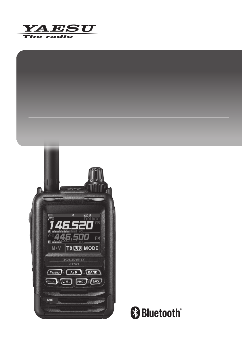
Selecting the Squelch Type in the Analog FM Mode
1. Press the [F MENU] key [SQTYP].
If [SQTYP] is not displayed, touch [FWD →] to display
[SQTYP] and then touch it.
2. Turn the DIAL knob and select the type of squelch, refer to the table below.
Tone squelch (CTCSS), DCS and the New PAGER (EPCS) functions do not operate in
the C4FM digital mode. Touch [MODE] to change to the Analog FM mode, or turn the
AMS function ON.
Squelch type
OFF
TONE
TONE SQL
DCS
REV TONE
PR FREQ
PAGER
D CD*
TONE-DCS*
D CD-TONE SQL*
Icon
indication
-
Description
Deactivates the tone squelch function and DCS function
OFF, then returns to the normal squelch operation in the
Analog FM mode.
Analog FM Transmissions contain the CTCSS tone.
Receives as a normal squelch operation.
Activates the CTCSS tone squelch function on Analog
FM receive.
Activates the Digital Code Squelch (DCS) function.
The DCS code may be selected from 104 codes (from
023 to 754).
Activates the reverse tone function.
Used to monitor communications based on the squelch
control system. When a signal contains the designated
tone, the squelch is not opened, and when the tone signal
disappears, the squelch opens, and communication starts.
Activates the no-communication squelch function for
radios.
The no-communication signal tone frequencies may
be specified within the range from 300 Hz to 3000 Hz
in steps of 100 Hz.
Activates a new two-tone CTCSS pager function.
When communicating with FT5DR/DE transceivers
among friends, specify personal codes (each code is
composed of two tones) so that only specific stations
are called.
Transmits the signal containing the DCS CODE.
Receives as a normal squelch operation.
Sends a tone signal when transmitting, and receives
the only signal matches the DCS code when receiving.
Sends the DCS CODE when transmitting and receives
only signals that contain a matching tone signal when
receiving.
9
*: Press and hold the [F MENU] key [SIGNALING] [10 SQL EXPANTION] set to
“ON”, “D CD”, “TONE-DCS” and “D CD-TONE SQL” setting values are activated.
3. Press the PTT switch to save the settings and return to normal operation.
• The squelch type may be set for each frequency band (BAND).
• The CTCSS and DCS squelch settings are also active during scanning. If scanning is
performed with the CTCSS and DCS squelch function activated, scanning stops only
when a signal containing the specified CTCSS tone or DCS code is received.
• Pressing the MONI/T-CALL switch allows signals that do not contain a tone or DCS code,
and signals with different tones, DCS codes, digital mode signals to all be heard.
• Press and hold the [F
the DCS code of the inverted phase.
] key [SIGNALING] [3 DCS INVERSION] allows to receive
MENU
Tone squelch feature
The tone squelch opens the speaker audio only when a signal containing the specified
CTCSS tone is received. The receiver will be quiet while waiting for a call from a specific
station.
The tone squelch function does not function in digital mode. Touch [MODE] to change the
communication mode to Analog FM mode or turn the AMS function ON.
Setting CTCSS Tone frequency
The tone frequency may be selected from 50 frequencies (from 67.0 Hz to 254.1 Hz).
1. Press the [F
If [SQTYP] is not displayed, touch [FWD →] to display [SQTYP] and then touch it.
2. Rotate the DIAL knob to select “TONE SQL”.
3. Press the PTT switch to save the settings and return to normal operation.
4. Press the [F
5. Rotate the DIAL knob to select the tone frequency.
6. Press the [BACK] key to save the setting and return to
normal operation.
MENU] key [SQTYP].
MENU] key] [CODE].
12 TONE SQL FREQ
TONE : 100.0 Hz
• The tone frequency setting is common with the squelch types as follows:
TONE, TONE SQL, REV TONE, TONE-DCS, D CD-TONE SQL
• The default setting is “100.0 Hz”
Searching for the CTCSS Tone transmitted by the other Station
The tone search function does not function in digital mode. Touch [MODE] to change the
communication mode to Analog FM mode or turn the AMS function ON.
Search and display the tone squelch CTCSS tone transmitted by the other station.
1. Press the [F
MENU] key [SQTYP].
If [SQTYP] is not displayed, touch [FWD →] to display [SQTYP] and then touch it.
2. Rotate the DIAL knob to select the “TONE SQL”.
3. Press the PTT switch to save the setting and return to normal operation.
10
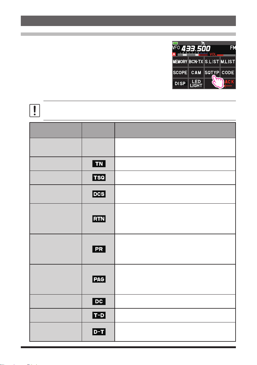
4. Press the [F MENU] key [CODE].
The setting screen of the tone frequency is displayed.
5. Touch [SEARCH].
• The transceiver begins searching for a matching
tone frequency.
12 TONE SQL FREQ
TONE : 123.0 Hz
• When a corresponding tone frequency is detected,
a beep sound is emitted, and the detected tone
frequency blinks. The searching stops for 5 seconds
and the audio is heard.
6. Touch [STOP] to stop searching.
7. Press the [BACK] key to save the detected tone frequency and return to normal
operation.
To set the transceiver operation when scanning stops, press and hold the [F
[SCAN] [4 SCAN RESUME]. This setting is common with the scan setting, tone search
function and DCS search function.
MENU
] key
Digital Code Squelch (DCS) feature
The Digital Code Squelch opens the speaker audio only when a signal containing the
specified DCS code is received.
The DCS code may be selected from 104 types (from 023 to 754).
The tone search function does not function in digital mode. Touch [MODE] to change the
communication mode to Analog FM mode or turn the AMS function ON.
Setting the DCS CODE
1. Press the [F MENU] key [SQTYP].
If [SQTYP] is not displayed, touch [FWD →] to display [SQTYP] and then touch it.
2. Rotate the DIAL knob to select “DCS”.
3. Press the PTT switch to save the setting and return to normal operation.
4. Press the [F
5. Rotate the DIAL knob to select the DCS code.
6. Press the [BACK] key to save the detected tone
frequency and return to normal operation.
MENU] key [CODE].
2 DCS CODE
DCS : 023
• The DCS code set by the above operation is the common setting for all transmissions
with a DCS Code (DCS, D CODE, T DCS, D TONE).
• The default DCS code is “023”.
11

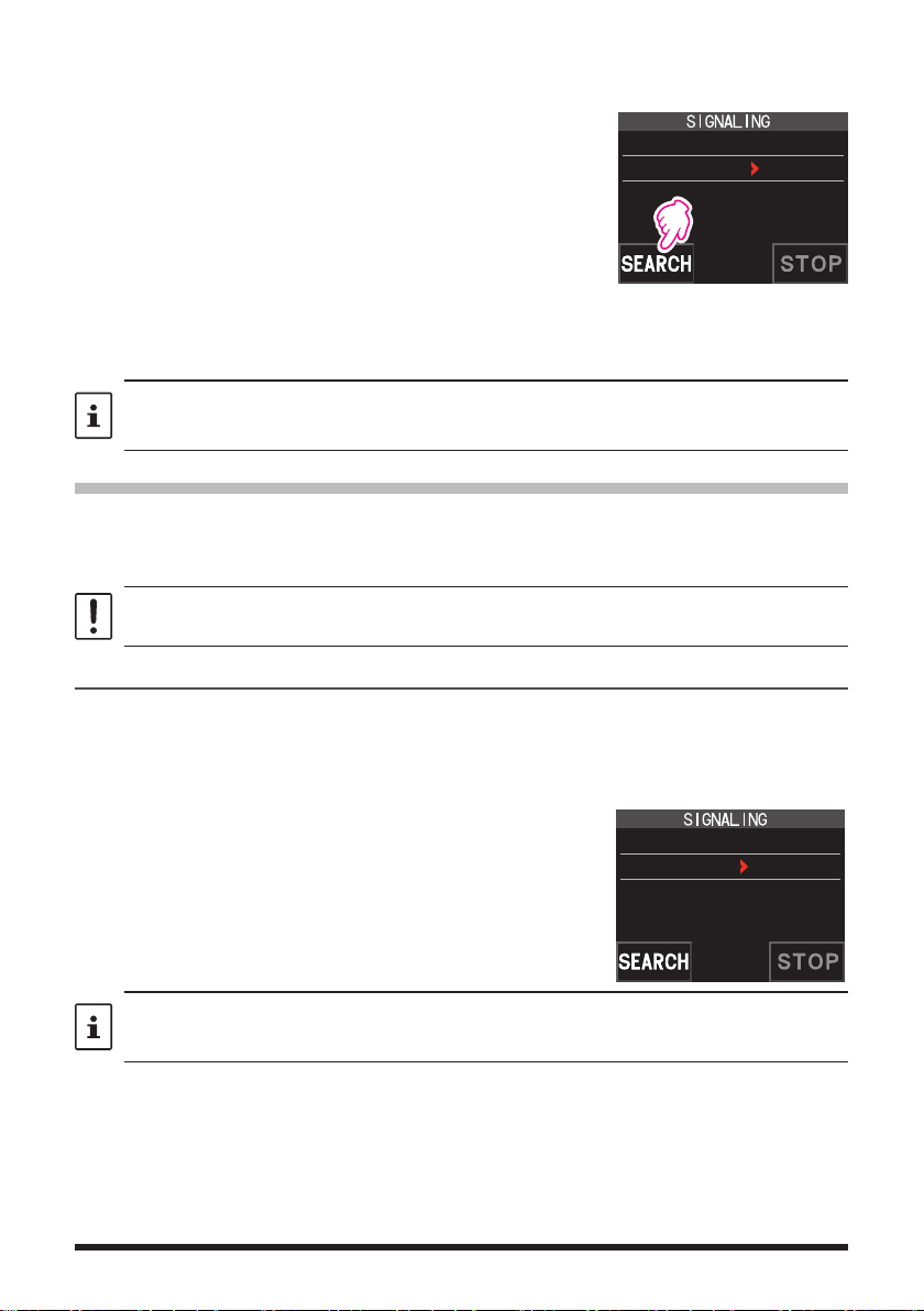
Searching for the DCS Code Used by the Other Station
Search for the DCS code used by the other station.
1. Press the [F
MENU] key [SQTYP].
If [SQTYP] is not displayed, touch [FWD →] to display [SQTYP] and then touch it.
2. Rotate the DIAL knob to select “DCS”.
3. Press the PTT switch to save the setting and return to normal operation.
4. Press the [F
MENU] key [CODE].
The DCS code setting screen is displayed.
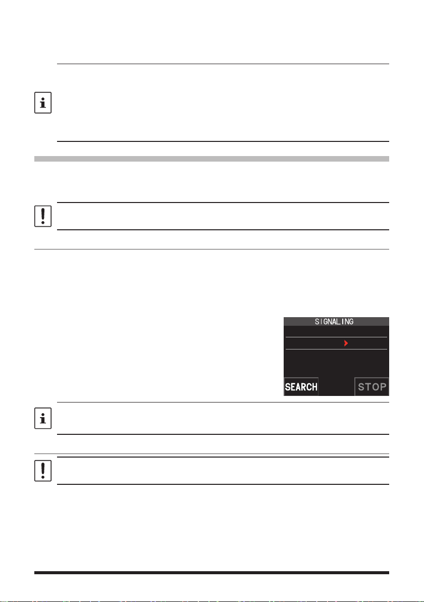
5. Touch [SEARCH].
• The transceiver starts to search for the DCS code.
• When a corresponding DCS code is detected, a
2 DCS CODE
DCS : 023
beep sound is emitted. The detected DCS code
blinks. The searching stops for 5 seconds and the
audio is heard.
6. Touch [STOP] to stop searching.
7. Press the [BACK] key to save the detected DCS code and return to normal operation.
To set the transceiver operation when scanning stops, press and hold the [F
[SCAN] [4 SCAN RESUME]. This setting is common for all scan settings, the tone search
function and DCS search function.
MENU
] key
Two-Tone CTCSS Pager Function
When using FT5DR/DE transceivers with a group of friends, setting the Two-Tone CTCSS
personal codes allows calling just the specific stations. Even when the person who is
called is not near the transceiver, the information on the LCD indicates that a call was
received.
The new two-tone CTCSS pager feature does not operate in digital mode. Touch [MODE] to
change the communication mode to Analog FM mode or turn the AMS function ON.
Using the Pager Function
1. Press the [F MENU] key [SQTYP].
If [SQTYP] is not displayed, touch [FWD →] to display [SQTYP] and then touch it.
2. Rotate the DIAL knob to select the “PAGER”.
3. Press the PTT switch to save the setting and return to normal operation.
Setting the Code for Your Station
Set the “pager code” to be called by other stations.
1. Activate the pager function by referring to “Using the pager function” above.
2. Press the [F
MENU] key [CODE].
If [CODE] is not displayed, touch [FWD →] to display [CODE] and then touch it.
12
3. Rotate the DIAL knob to select “CODE-RX”.
6 PAGER
ANS-BACK: OFF
CODE-RX : 05 47
CODE-TX : 05 47
4. Press the [F MENU] key to move the “u” icon to the first
element of the code.
Rotate the DIAL knob to select the first element of the
code from 01 to 50.
6 PAGER
ANS-BACK: OFF
CODE-RX : 05 47
CODE-TX : 05 47
5. Press the [F MENU] key to move the “u” icon to the
second element of the code.
Rotate the DIAL knob to select the second element of
the code from 01 to 50.
The same code cannot be use for both elements.
6 PAGER
ANS-BACK: OFF
CODE-RX : 05 47
CODE-TX : 05 47
6. Press the PTT switch to save the setting and return to
normal operation.
• The reverse combination works as the same code, that is “05 47” is the same as “47 05”.
• If the same code is specified for all individuals, all the individuals can be called at the
same time.
• The default code is “05 47”.
• When receiving the signals, the intermittent sound of the tone signal may be heard slightly.
Calling a Specific Station
The “pager code” may be set to call specific stations.
1. Activate the pager function by referring to “Using the Pager Function” (page 12).
2. Press the [F
MENU] key [CODE].
If [CODE] is not displayed, touch [FWD →] to display [CODE] and then touch it.
3. Rotate the DIAL knob to select “CODE-TX”.
4. Press the [F
MENU] key to move the “u” icon to the first element of the code.
Rotate the DIAL knob to select the first element of the code from 1 to 50.
5. Press the [F
MENU] key to move the “u” icon to the second element of the code.
Rotate the DIAL knob to select the second element of the code from 1 to 50.
The same code cannot be use for both elements.
6. Press the PTT switch to save the setting and return to normal operation.
7. Press the PTT switch to transmit a call to the specific station.
13
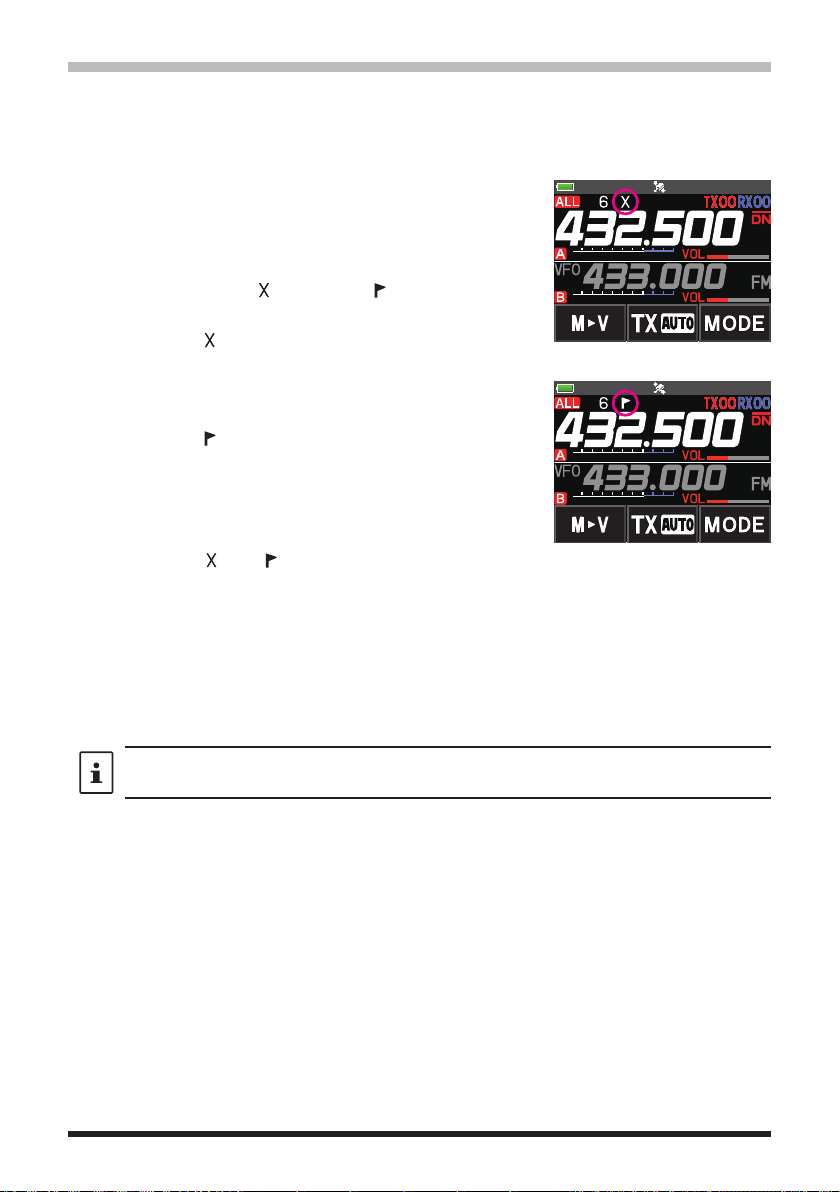
Receiving “pager code” calls from a Remote Station (Standby Operation)
When the Pager function is activated, and a call is received with a corresponding Code,
the audio is heard. When the PTT switch is pressed, the “
” icon blinks and the other
station's audio is heard regardless of whether the code matches or not. About 10 seconds
after the signal disappears, the “
” icon will light, and the sound of the unmatched
signal will not be heard.
Furthermore, when the Bell function (see below) is activated, the bell rings and the “
” icon
blinks when receiving calls from the other station.
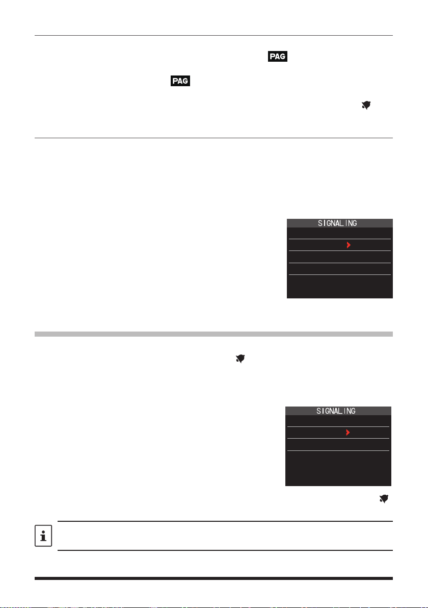
Using the Pager Answer Back
when called by another station with a corresponding pager code, the transceiver is automatically placed in the transmit mode (for about 2.5 seconds) to notify the other station
that you are ready to communicate.
1. Activate the pager function by referring to “Using the Pager Function” (page 12).
2. Press the [F
MENU] key [CODE].
If [CODE] is not displayed, touch [FWD →] to display [CODE] and then touch it.
3. Press the [F
to select “ON”.
MENU] key, and then rotate the DIAL knob
6 PAGER
ANS-BACK: ON
CODE-RX : 05 47
CODE-TX : 05 47
4. Press the PTT switch to transmit a call to the specific station.
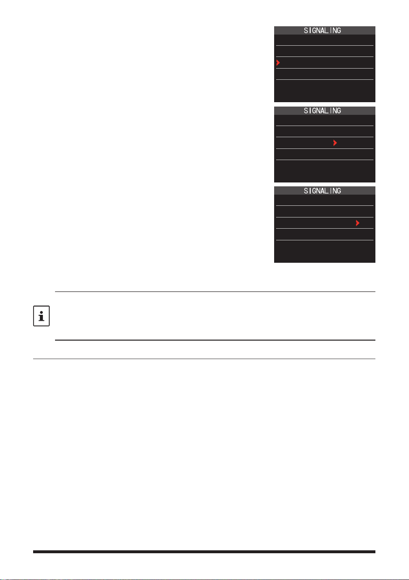
Notification of a Call from a Other Station by the Bell Function
The Bell may be set to sound an Alert when a call from another station containing a corresponding tone, DCS or pager code is received. “
” icon on the display blinks to provide
a later notice of the call from the other station.
1. Press and hold the [F
2. Press the [F
MENU] key.
MENU] key touch [SIGNALING] [1 BELL].
3. Rotate the DIAL knob to select “BELL”.
4. Press the [BACK] key, and then rotate the DIAL knob to
select “RINGER”, and then press the [F
MENU] key.
5. Rotate the DIAL knob to select the desired number of
1 BELL
SELECT : BELL
RINGER : 1time
times (1-20 times or continuous) the Bell rings.
• • • 1time ↔ 2times ↔ • • • ↔ 20times ↔ CONTI • • •
6. Press the PTT switch to save the setting and return to normal operation, and the “ ”
icon appears on the display.
If the setting is “CONTI” (continuous), the bell keeps sounding until an operation is made.
14

User Programmed Reverse CTCSS Decoder
The tone signal frequency can be set at 100 Hz intervals between 300 Hz and 3000 Hz
to mute the audio when receiving a signal containing a CTCSS tone matching the programmed tone.
1. Press the [F
2. Rotate the DIAL knob to select “PR FREQ”.
3. Press the PTT switch to save the setting and return to
normal operation.
4. Press the [F
The setting screen containing the CTCSS tone
frequencies is displayed.
5. Rotate the DIAL knob to select the desired CTCSS
tone frequency.
300Hz to 3000Hz (100Hz steps)
6. Press the PTT switch to save the setting and return to
normal operation.
MENU] key [SQTYP].
MENU] key [CODE].
7 PR FREQUENCY
1600Hz
15
Memory Function
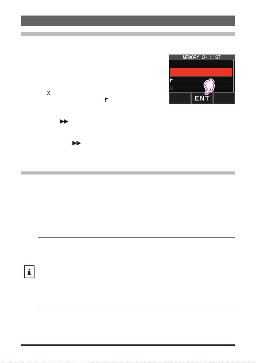
Memory Channel List
Since memory channels are displayed in a list, you can easily recall the memory by
checking the frequency and memory tag display.
1. Press the [F
• If [MEMORY] is not displayed, touch [FWD →] to
display [MEMORY] and then touch it.
• You can switch between memory tag display and
frequency display by press and hold the [V/M •] key.
• The “ ” icon is displayed at the left of memory channels
set as skip memory, and the “
left of memory channels set as specified memory.
• Deleted memory channels are displayed in gray text.
• Touching [
channel to blink. Then turning the DIAL knob will fast
forward memories in 10 channel steps. To cancel fast
forward, touch [
2. Rotate the DIAL knob to select the desired memory channel.
3. Touch [ENT] to recall the selected memory channel and enter memory mode.
The Memory Channel Only Mode
The FT5DR/DE may be set to operated only in the registered memory channels.
1. While pressing the [V/M •] key, press and hold the POWER switch to turn the
transceiver ON.
• The memory channel only mode is ON, the previously selected memory channel is
recalled.
• Rotate the DIAL knob to select the memory channels.
• Touch and hold the frequency display to display the numeric keypad, enter a 3-digit
memory channel number, and then touch [ENT] to recall the memory channel.
• In the memory only mode, only the following functions will operate:
• Pressing the [V/M •] key, will sound the beep, “M-ONLY” will be displayed, and the
zCanceling Memory Only Mode
1. Turn the transceiver OFF; and then while pressing the [V/M •] key, press and hold the
POWER switch to turn the transceiver ON.
MENU] key [MEMORY].
1 145.030.00
2 439.700.00
3 145.620.00
4 432.500.00
” icon is displayed at the
], will cause the 10 digits of the memory
] again.
• Changing the communication mode (touch [MODE])
• The transmission mode setting of the AMS function (touch [TX AUTO], [TX FM] or [TX DN])
• Switching MAG groups (press the [BAND] key)
• Audio level adjustment
• Key lock function (press the POWER switch)
• Function menu MEMORY, DISP, LED LIGHT, SCAN, and D.RCV functions
• SQL level adjustment (press the [SQL] key)
• Group monitor (GM) function (press the [GM] key)
• WIRES-X function (press the [X] key)
function will not operate.
16
Using Memory Banks
The transceiver allows using up to 24 memory banks to be recalled with the sorted memory channels. One memory channel may also be registered in two or more memory banks
according to the intended use.
Example of registering memory channels to the memory banks:
Memory channels Memory banks
1 145.000 MHz
2 145.500 MHz
3 120.400 MHz
4 5 439.700 MHz
6 432.800 MHz
7 108.700 MHz
8 9 10 -
~
900 -
Registering to Memory Banks
1. Press the [V/M •] key to enter the memory mode.
2. Rotate the DIAL knob to recall the memory channel to
register in the memory bank.
BANK1 (1 - 100) 144 MHz Amateur Band Channels
BANK2 (1 - 100) 430 MHz Amateur Band Channels
BANK3 (1 - 100)
BANK4 (1 - 100) All Amateur Band Channels
BANK5 (1 - 100)
BANK6 (1 - 100) Air Band Channels
BANK7 (1 - 100)
BANK8 (1 - 100)
BANK9 (1 - 100)
BANK10 (1 - 100)
~
BANK24 (1 - 100)
3. Press and hold the [V/M •] key.
Memory channel will blink.
BANK 1
4. Rotate the DIAL knob to select the memory bank (BANK1
to BANK24) to register the memory channel.
The memory bank channels are displayed between the memory channel 1 (1CH), and
PMS memory channel U50.
5. Press the [V/M •] key.
The memory channel is registered in the selected memory bank and the transceiver
operation returns to the memory mode.
17
Open the Memory Bank display
1. Press the [V/M •] key to enter the memory mode.
2. Press the [F
MENU] key [BANK].
If [BANK] is not displayed, touch [BACK ←] to
Memory Bank Number
Memory Channel Number
display [BANK] and then touch it.
B1 to B24: The memory bank display
: The memory channel display
If no memory channel is registered, setting the following operation sounds the beep and “NO
BANK” will be displayed.
zDisable the memory bank display
1. Press the [F
MENU] key [MR].
If [MR] is not displayed, touch [BACK ←] to display [MR] and then touch it.
Open Memory Bank Channels
1. While the memory bank is displayed, press the [BAND] key.
2. Rotate the DIAL knob to select the memory bank (BANK1 to BANK24) to be recalled.
If no memory channel is registered, the memory bank may not be selected.
3. Press the [BAND] key or PTT switch.
The selected memory bank is activated.
Canceling a Memory Channel Registered in Memory a Bank
1. Recall the memory bank to cancel registering.
2. Press and hold the [V/M •] key.
3. Rotate the DIAL knob to select the memory channel to cancel registering to the
memory channel.
4. Touch [
], and then touch [M.DEL].
18

Assigning a Name to a Memory Bank
A name can be assigned to a memory bank using up to 16 characters.
The following types of characters can be entered:
• Alphabetic characters (1 byte and 2 byte letters, uppercase and lowercase
characters)
• Numbers (1 byte and 2 byte numbers)
• Symbols
1. Press and hold the [F
MENU] key touch [MEMORY]
[2 BANK NAME].
2. Touch the bank where you want to edit the tag.
• The character input screen is displayed.
• Use the numeric keys or DIAL knob, to input the
name characters.
• Touch 【
】: to move the cursor to the right
• For additional details on inputting a memory tag,
refer to “Text input screen” in the Operating Manual.
The default memory bank names are set from “BANK 1” to
“BANK24. Each name may be changed.
3. When input is complete, press the PTT switch to save
the characters and return to normal operation.
19
Split Memory
Two different frequencies, one for receive and another for transmit, may be registered to
a memory channel.
1. Register the receive frequency to a memory channel first.
• For additional details on registering to a memory channel,
refer to the “Registering to Memory Channels” in the
Operating Manual.
2. Set the transceiver to the desired transmit frequency.
3. Press and hold the [V/M •] key .
4. Rotate the DIAL knob to select the channel number that
the receive frequency was registered to on step1.
5. While pressing and holding the PTT switch, press the
[V/M •] key.
• The beep sounds and the split memory is saved.
• While recalling the split memory, “
” is displayed on
the LCD.
Registering the receive
frequency.
Registering the transmit
frequency.
Recalling the split memory
While operating the split memory, Press the [F
and receive frequencies temporarily. When reversing the frequencies,“
key [REV], to reverse the transmit
]
MENU
20
” will blink.
Setting Skip Memory Channel and Specified Memory Channel
For efficient memory channel scanning, two types of memory channels may be designated, “skip memory channels” and “specified memory channels”. Set “Skip Memory Channels” will be skipped during the memory scanning; and only “Specified Memory Channels”
will be scanned during specified memory channel scanning.
1. Recall the memory channel to skip or specify.
2. Press and hold the [F
[5 MEMORY SKIP].
3. Rotate the DIAL knob to change as follows:
• • • OFF SKIP
• SKIP: Skip Memory Channel
” at the right of the memory channel
The “
number lights up, and then the channel is
skipped during scanning of memory channels.
• SELECT: Specified Memory Channel
The “
” at the right of the memory channel
number lights up, and then only designated
memory channels are scanned during memory
scanning.
• OFF: Normal Memory Channel
The “
” or “ ” at the right of the memory
channel number turns OFF.
zScanning Only the Specified Memory Channels
1. Recall the memory channel registered as a specified memory channel.
2. Press the [F
MENU] key [SCAN].
• If [SCAN] is not displayed, touch [BACK ←] to display [SCAN] and then touch it.
• Only the memory channels registered as the specified memory channels are
scanned.
MENU] key touch [MEMORY]
SELECT • • •
Skip Memory
Specified Memory
Unless two or more specified memory channels are registered, the specified memory
channel scanning does not function.
21
Skipping Unwanted Scan Frequencies (Skip Search Memory)
During the VFO scan, an unwanted frequency may be skipped by registering it to the “skip
search memory channels” in advance.
zSet the temporary scan stop to the skip search memory
1. Press and hold the [V/M •] key to temporarily stop the VFO scan.
2. Rotate the DIAL knob to select a skip search memory channel from 901-999.
Only skip search memory channels 901-999 may be selected.
3. Press the [V/M •] key.
The beep sounds, and the search skip channel is saved to memory, then the scan
resumes.
zSpecifying Unwanted VFO Scan Frequencies
1. In the VFO mode, set the frequency that you do not want to receive.
2. Register the skip search memory (901-999) with the same steps as “Registering to
Memory Channels” (see the Operating Manual).
The skip search memory may be deleted with the same steps as “Clearing Memories” (see
the Operating Manual). The deleted frequency is scanned again.
Programmable Memory Channel Scan (PMS)
Registering to the Programmable Memory Channels
50 sets of PMS memory channels (L1/U1 to L50/U50) are available.
• Register the lower and upper frequencies of the frequency range in a pair of
Programmable Memory Channels.
L££: Lower limit memory channel
U££: Upper limit memory channel
• For more details on registering frequencies to the memory channel, refer to the
“Registering to Memory Channels” in the Operating Manual.
• Make sure to use the corresponding numbers for the lower and upper limit memory
channels.
• Set the PMS memory channel for performing the Programmable Memory scanning (PMS)
as follows:
• The scan width of the upper and lower limit frequencies must be 100 kHz or more.
• The lower and upper limit memory channels must be within the same frequency band.
• The lower and upper limit memory channels must not be registered in reverse.
• The PMS memory channel must not be registered as a skip memory channel.
Performing Programmable Memory Channel Scan
The programmable memory channel scan allows scanning a specified frequency range
within the same frequency band.
1. Recall the PMS memory channel to which the lower limit (L££) or upper limit (U££)
of the frequency band is registered.
2. Press the [F
MENU] key [SCAN].
• If [SCAN] is not displayed, touch [BACK ←] to display [SCAN] and then touch it.
• Programmable memory channel scanning starts.
• During scanning, “PMSP££” appears on the upper left side of the display.
• If the DIAL knob is rotated while scanning is in progress, the scanning will continue
up or down in frequency according to the direction of the DIAL Knob rotation.
22

• If the scanner halts on an incoming signal, the back light will turn ON and the
decimal point between the “MHz” and “kHz” digits of the frequency display will blink.
• Scanning will resume in about five seconds.
3. Touch [STOP] or press the PTT switch to cancel the scanning.
In this state (displayed as “PMSP££” at the upper left of the display), the frequency
can be changed by turning the DIAL knob only in the upper/lower limit frequency
range stored by PMS memory.
zDisable the PMS function
1. Press the [V/M •] key.
Return to the normal memory mode.
Memory Bank Scanning
Scan only the memory channels stored in the recalled memory bank.
1. Recall the memory bank you want to scan by referring to “Open the Memory Bank
display” (page 18) and “Open Memory Bank Channels” (page 18).
2. Press [F
MENU] [SCAN].
If [SCAN] is not displayed, touch [BACK ←] to display [SCAN] and then touch it.
Memory bank scan starts.
Memory Bank Link Scanning
During regular memory bank scanning, only the memory channels assigned to the
recalled memory bank are scanned. During memory bank link scanning, you can scan
memory channels registered in two or more banks you specified in advance.
Setting Bank Link
1. Press and hold the [F MENU] key touch [MEMORY] [1 BANK LINK].
2. Rotate the DIAL knob to select the memory bank for which you want to perform bank
link scanning.
3. Press the [F
4. Repeat steps 3 and 4 to select other memory banks.
5. Press the PTT switch to save the setting and return to normal operation.
Performing Bank Link Scan
1. Recall the memory bank set as bank link by referring to “Open the Memory Bank
display” (page 18) and “Open Memory Bank Channels” (page 18).
The memory bank number is changed from [B] to [b] and the bank link scanning is
activated.
2. Press the [F
If [SCAN] is not displayed, touch [BACK ←] to display [SCAN] and then touch it.
Bank Link Scanning is performed toward the higher memory channel numbers.
Press and hold the [DISP] key touch [SCAN] [5 SCAN WIDTH] [BANK LINK] is set
to “OFF”, to temporarily disable banklink and perform normal memory-bank scanning while
banklink is set.
MENU] key, a check mark will appear and it will be set to Bank Link.
MENU] key [SCAN].
23

Dual Receive (D.RCV) Function
The transceiver is equipped with the following 3 types of Dual Receive Functions:
• VFO Dual Receive
• Memory Channel Dual Receive
• Home Channel Dual Receive
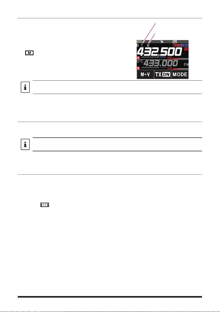
The transceiver checks for signals on the frequency registered to the selected memory
channel (Priority Memory Channel) once approximately every 5 seconds. When receiving
a signal on the frequency registered to a priority memory channel, the Dual Receive function automatically pauses, and allows reception of the signals.
Example: Checking the priority memory channel “6” (432.500 MHz), while receiving
“145.240 MHz”.
The transceiver monitors signals
VFO
on the frequency registered to the
Priority Memory Channel, once
approximately every 5 seconds.
Priority
Memory Channel
The transceiver returns to
the previous frequency
quickly and continues to
receive mode when there
is no signal.
When the transceiver receives
a signal on the frequency registered
to the priority memory channel, dual
reception stops and signal receiver
switches to priority memory channel.
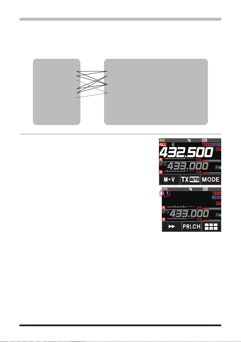
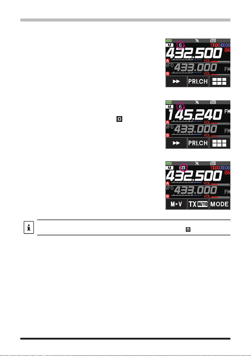
Registering the priority channel
1. Register the preferred receive frequency and communication mode to the priority
memory channel (see the operating manual).
2. Press the [V/M •] key to recall the memory channel.
3. Touch and hold the [F
MENU] key, and then rotate the
DIAL knob to select the memory channel registered in
step 1.
4. Touch [PRI.CH].
• The priority memory channel setting is saved and
operation returns to the prior recalled memory
channel.
• When recalling the priority memory channel, the “
”
icon appears on the upper right side of the memory
channel number.
24

Activating the Dual Receive (D.RCV) feature
1. Set the frequency and communication mode to monitor continually.
The monitor frequency may be set on the VFO mode, the memory channel mode or
the HOME channel mode.
VFO Dual Receive
VFO Priority Memory Channel
Memory Channel Dual Receive Memory Channel Priority Memory Channel
HOME Channel Dual Receive HOME channel
Priority Memory Channel
2. Press the [F MENU] key [D.RCV].
• If [D.RCV] is not displayed, touch [BACK ←] to display
[D.RCV] and then touch it.
• The dual receive function is activated and the following
icon is displayed on the top left of the display.
VFO Dual Receive: VDR
Memory Channel Dual Receive: MDR (/DXX/dXX)*
HOME Channel Dual Receive: HDR
*
In the memory bank, DXX is displayed, and in the
memory bank where the bank link is set, dXX (XX is
a bank number) is displayed.
When a signal is received on the priority channel, the beep sounds, and the Dual
Receive function stops temporarily.
The combination of the frequency bands and modes for the Priority Memory Channel and
the receiver monitor frequency can be easily changed. Dual Receive may be operated with
the AMS function ON.
Setting the Dual Receive (D.RCV) Resume Conditions
1. Press and hold the [F MENU] key touch [SCAN] [4 SCAN RESUME].
2. Rotate the DIAL knob to select
3. Press the [F
MENU] key, and then rotate the DIAL knob to select the resume condition
“DW”.
after halting in the Dual Receive function (default setting is “HOLD”).
2.0 sec~10.0 sec The signal is received for the specified period of time, and then
the Dual Receive resumes.
The Dual Receive resume time may be set from 2 to 10 seconds
at 0.5 second intervals.
BUSY
The signal is received until the signal fades out. Two seconds
after the signal fades out, the Dual Receive resumes.
HOLD The Dual Receive stops and tuning remains on the current
receive frequency. (The Dual Receive does not resume.)
4. Press the PTT switch to save the new setting and return to normal operation.
Press and hold the [F
“ON”, press the
channel. After transmitting, the transceiver receives the priority channel and Dual Receive
resumes after 5 seconds.
PTT
switch to transmit, without waiting for activity to appear on the priority
] key touch [
MENU
SCAN
6 PRIORITY REVERT
] [
] is set to
25

Using the GPS Function
The GPS Function
GPS (Global Positioning System) is a space-based satellite navigation system that
provides location and time information anywhere on the earth. It was developed by the
U.S. Department of Defense as a military system. When the GPS receiver acquires 3
or more signals (of about 30) GPS satellites orbiting at an altitude of about 20,000 km,
it can calculate and display its current position (latitude, longitude, and altitude) within a
tolerance of several meters. In addition, GPS can receive the exact time from the satellite
onboard atomic clock.
Activating the GPS Function
Activating the GPS function enables the transceiver to automatically obtain the internal
clock setting, and your location information setting from the GPS data.
The default setting is ON.
1. Press and hold the [F MENU] key touch [APRS] [20 GPS POWER].
2. Rotate the DIAL knob to select “GPS ON”.
3. Press the PTT switch to save the setting and return to normal operation.
When the GPS function is active, the power consumption increases by about 15 mA. As a
result, the battery life is reduced, as compared to when the GPS function is deactivated.
Displaying Position Information of Remote Stations in Digital Mode
With V/D mode of the C4FM digital, the GPS position information is transmitted simultaneously
with voice signals; therefore, the direction and position of the remote station can be displayed
in real-time even while communicating.
For details, see “Real-Time Navigation Function” (page 30)
• Even if the GPS function of your station is set to OFF, the position information of the
remote station can be displayed in V/D mode.
• When the GPS function is not active, the remote station cannot display the position
information for your station.
26

About Positioning by GPS
“Positioning” refers to calculation of your current position from the satellite orbit
information and radio propagation time. At least 3 satellites need to be acquired for
successful positioning. If positioning fails, move away from buildings as far as possible
and stand in an area with open sky.
• About errors
The measurement environment may result in positioning errors of several hundred
meters. Under favorable conditions, positioning can be performed successfully using
only three satellites. However, under the following poor conditions, the positioning
accuracy can decrease or positioning can fail.
• Between tall buildings
• Narrow paths between buildings
• Indoors or near large buildings
• Under elevated roads or high voltage power lines
• Between trees such as in forests or woods
• Inside a tunnel or underground
• Through heat reflective glass
• Areas with strong magnetic fields
• When not in use for a long time
When using the GPS functions for the first time after purchase, or when it has been
unused in a while, a few minutes may be required to acquire the satellites. Also, if the
GPS function has been turned OFF for several hours, a few minutes may be required
to search for satellites.
27

Saving GPS Information (GPS Log Function)
The GPS position information can automatically be saved periodically onto a microSD
memory card. Using the saved data, tracks can be displayed on commercially available
map software*.
* Technical support for the map software is not provided by YAESU.
1. See “Activating the GPS Function” on page 26, and activate the GPS function.
2. Press and hold the [F
3. Rotate the DIAL knob to select the GPS data logging interval.
OFF / 1 sec / 2 sec / 5 sec / 10 sec / 30 sec / 60 sec
4. Press the PTT switch to save the setting and return to normal operation.
The GPS log function is activated, and GPS log
• The position information is saved periodically unless “OFF” is selected in step 3 (shown
above) or the power of the transceiver is turned off.
• Reselecting the GPS data logging interval in step 3 or turning on the transceiver again,
begins saving the GPS data under a different file name.
Checking Tracks on Your PC
1. Turn off the transceiver.
2. Remove the microSD memory card from the transceiver.
3. Connect the microSD memory card to your PC using a commercially available memory
card reader.
4. Open the “FT5D” folder in the microSD memory card.
5. Open the “GPSLOG” folder.
• The data is saved as “GPSyymmddhhmmss.log”.
• The [yymmddhhmmss] part of the name consists of year (yy), month (mm), day
(dd), hour (hh), minute (mm), and second (ss).
• Tracks can be displayed on the map by importing the data to commercially available
map software.
• For information on importing, please refer to the operation manual for the map software
you use.
MENU] key touch [CONFIG] [7 GPS LOG].
“
icon will be displayed.
”
28

GPS Screen Information and Operation
Activating the GPS function displays the following information on the LCD.
1. In the normal operation screen, press the [F
• If [D.RCV] is not displayed, touch [BACK ←] to display [D.RCV] and then touch it.
• If the navigation screen is displayed, touch the compass display to switch to the
GPS information screen.
MENU] key touch [DISP].
①
②
③
④
⑤
⑥
① Displays the satellite azimuth and elevation angles. Displays in North-up mode.
② Displays the date and time.
③ Displays the current speed.
④ Displays the satellite number and reception level.
⑤ Displays the latitude on the upper side of the screen whereas displays the longitude
on the lower side of the screen.
The current position appears using north (N) or south (S) latitude.
Display format: X DD° MM. MMM
X: X=N: North latitude, X=S: South latitude, DD: Degree, MM:MMM Minute
Example: N 35° 37.250 (35 degrees, 37 minutes, 15 seconds north latitude)
The current position appears using east (E) or west (S) longitude.
Display format: X DDD° MM. DMMM
X: X=E: East longitude, X=W: West longitude, DDD: Degree, MM:MMM Minute
Example: E 139° 44.500 (139 degrees, 44 minutes, 30 seconds east latitude)
⑥ Displays the altitude of the current position “ALTI xxxxm”.
Example: ALTI 36m
• The GPS data units for position, speed and altitude may be changed by pressing and
holding the [F
• When the GPS function is used, the accurate time and date are obtained from GPS and
shown on the LCD in 24-hour format. This time data is displayed on the GPS and APRS
screens.
• The geodetic system datum (WGS-84 / Tokyo) of the built-in GPS unit may be selected
by
pressing and holding the [F
Menu. However, since APRS uses the geodetic system of WGS-84, it is recommended not
to change it.
• The time zone may be set at 30-minute increments by press and hold the
touch [APRS] [
• The position information obtained from an external GPS device may be used by pressing
and holding
setting “INPUT” to “GPS”. In this case, the data from the internal GPS will be ignored.
• When using an external GPS device, move it away from the transceiver to reduce
interference.
] key touch [APRS] [22 GPS UNIT].
MENU
] key touch [APRS] [
MENU
28 TIME ZONE
the [F
MENU
]
(the default setting: UTC 0:00).
] key touch [APRS] [
19 GPS SETUP] in Setup
[F
MENU
17 COM PORT SETTING
] key
]
and then
29
Smart Navigation Function
There are 2 methods of navigation with the Smart Navigation function.
• Real-time navigation function
• Backtrack function
Before using the smart navigation function, press and hold the [F
[1 TARGET LOCATION], select “COMPASS”.
] key touch [APRS]
MENU
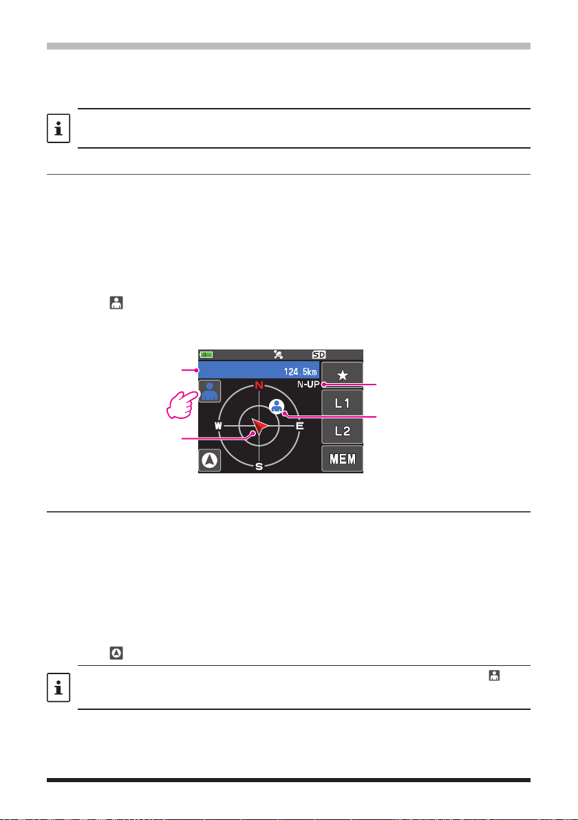
Real-Time Navigation Function
GPS position information and voice signals are simultaneously transmitted in the V/D
mode of C4FM digital. For this reason, the position and direction of the remote station can
be displayed in real time even during communication.
1. In the normal operation screen, press the [F
MENU] key touch [DISP].
• If [DISP] is not displayed, touch [FWD →] to display [DISP] and then touch it.
• If the GPS information screen is displayed, touch the compass display to switch to
the navigation display screen.
2. Touch [ ] to switch to the remote station location information display.
3. The distance and direction to the remote station operating on the same frequency in
the V/D mode are displayed.
Callsign and distance to
partner station
Progress direction of
own station
JA1YOE-123
H-UP: Heading Up
N-UP: North Up
Direction of remote station
4. Press the [F MENU] key to return to the normal operation display.
Backtrack Function
By registering a point such as the departure point in advance, the distance and direction
to the registered point from your current position can be displayed in real time.
zRegistering Your Current Position (Departure Point)
(up to 3 Positions can Be Registered)
1. In the normal operation screen, press the [F
MENU] key touch [DISP].
• If [DISP] is not displayed, touch [FWD →] to display [DISP] and then touch it.
• If the GPS information screen is displayed, touch the compass display to switch to
the navigation display screen.
2. Touch [ ] to switch to your own station location information display.
You can register the other partner's callsign and current location by touching [ ] and
performing the registration operation while the remote station's location information is
displayed.
30

3. Touch [MEM].
Distance to the registered
“★”, L1” and “L2” blink.
H-UP
4. Touch one of the blinking indicators to which you want
to register the position information.
• The location information is registered with the
H-UP
selected indicator.
5. Press the [F
MENU] key return to normal operation
display.
zUsing the Back Track Function
1. In the normal operation screen, press the [F
MENU] key touch [DISP].
• If [DISP] is not displayed, touch [FWD →] to display [DISP] and then touch it.
• If the GPS information screen is displayed, touch the compass display to switch to
the navigation display screen.
2. Touch the indicator ([★], [L1] or [L2]) to which you want to register the location
information for back tracking.
The arrows in the circle indicate the direction of the
registered point (departure point). You can return to the
departure point by moving forward so that the arrow
H-UP
always points up (In case of heading up display).
3. Press the [F
MENU] key to return to normal operation
display.
zDescription of the BACK TRACK Function Screen
DISTANCE
Direction of registration
point
31
position
H-UP: Heading Up
N-UP: North Up
Registration point

Functions to Use as Necessary
AF-DUAL Receive Function
The AF-DUAL Receive Function allows reception of a radio broadcast during standby
reception of A-band or B-band frequency (or frequency registered to a memory channel).
When standby reception is active, no audio is heard on the standby frequency, however
if a voice signal is detected, the reception of the broadcast radio will be paused, and the
receiver frequency will be heard.
Dual Receive is a similar function. When using the Dual Receive function, every time the
transceiver checks for a signal on the specified memory channel during radio reception,
the radio reception is interrupted (approximately every 5 seconds). When using the
AF-DUAL Receive Function, the radio reception is interrupted only when there is a calling
signal from another transceiver.
1. Set the A-band or B-band frequency for standby receive during broadcast radio
reception.
2. Press the [F
If [A.DUAL] is not displayed, touch [BACK ←] to
•
display [A.DUAL] and then touch it.
• The AF-DUAL function is activated, and AF DUAL
“
• Pressing the [BAND] key each time switches
between the AM broadcast (middle wave band) and
FM broadcast.
3. Rotate the DIAL knob to tune to the frequency of the
broadcast station.
MENU] key [A.DUAL].
” icon will be displayed.
• The AF-DUAL receive function can also be used to monitor a radio frequency registered
to a memory channel or memory bank.
• Pressing [MONI] switch during radio reception, allows receiving the standby frequency.
• While listening to the radio using the AF-DUAL function, in standby receive mode, the
transceiver cannot simultaneously receive broadcasts on the AM frequency (middle wave
band) on either the A-band or B-band, and FM frequency.
zDisable the AF DUAL function
1. Press the [F
MENU] key [A.DUAL].
32

DTMF Operation
DTMF (Dual Tone Multi Frequencies) are the tone signals sent to make telephone calls,
or control repeaters and network links. Up to 10 registers of 16-digit DTMF tone codes
can be stored as telephone numbers to make calls through the public telephone network
using a phone patch or connect through the WIRES-X analog node station.
Setting the DTMF Memory
1. Press and hold the [F MENU] key touch [SIGNALING] [5 DTMF MEMORY].
2. Rotate the DIAL knob to select the desired channel (1 to 10) to register the DTMF
code, then press the [F
The DTMF memory channel input screen is displayed.
3. Use the numeric keypad or DIAL knob to input the DTMF code maximum of 16 digits.
• Using the DIAL knob:
The DTMF codes from 0 to 9 may be input.
0 to 9
• • •
4. Press the PTT switch to save the setting and return to normal operation.
Transmitting the Registered DTMF Code
1. Press and hold the [F MENU] key touch [SIGNALING] [4 DTMF MODE].
2. Rotate the DIAL knob to select the “MODE”.
3. Press the [F
AUTO
MANUAL: The DTMF code may be transmitted manually by pressing each numeric
4. Press the PTT switch to save the setting and return to normal operation.
When set to “AUTO”, the DTMF icon “
MENU] key, and then turn the DIAL knob to select the setting.
: The registered DTMF code is automatically transmitted.
key.
Transmitting DTMF code automatically using DTMF memory
1. Set “AUTO ” by referring to “Transmitting the Registered DTMF Code” (above).
2. While pressing and holding the PTT switch, touch [DTMF].
3. Touch a numeric [0] to [9].
• The DTMF code registered in the DTMF memory channel is automatically
transmitted.
• Even after releasing the PTT switch, the transmission continues until the DTMF
code is completed. The transceiver is automatically returned to receive mode.
Manually Transmitting the DTMF Code
1. Set “MANUAL” by referring to “Transmitting the Registered DTMF Code” (above).
2. While pressing and holding the PTT switch, touch [DTMF].
• Touch each corresponding key to send the DTMF code
• The transmission may continue for one second after releasing the PTT switch.
MENU] key.
A to D
* - #
• • •
” will be shown on the display.
33

Using the Transceiver for Packet Communication
You can perform packet communication with your transceiver by connecting a TNC (Terminal Node Controller) using an optional Microphone Adapter (CT-44).
MIC/SP jack
TNC
CT-44
EAR
MIC
10 F
2 kΩ
After connecting the TNC to the transceiver, set the output signal level to the TNC by
adjusting the sound volume level of the transceiver.
Also, adjust the signal level input to your transceiver using the output level adjustment
volume on the TNC (Input level cannot be adjusted on your transceiver).
When sending a vast volume of data, the transmission takes a longer time and the
transceiver may be overheated. If the transmission is continued for a long time, the
overheat prevention circuit will operate and the transmission power decreases. If the
transmission is continued further, the transmission will be automatically stopped to
prevent the transceiver from overheating and consequently malfunctioning. If the overheat
prevention circuit has operated the transceiver returns to the receive mode, turn the
transceiver OFF, or leave it in the receive mode until the temperature falls.
SP
GND
μ
MIC
PTT
GND
• Set the receive battery Save Function to OFF during packet communication by pressing
and holding the [F
• Reception can be interfered with by noise generated by the Personal Computer.
• If the transceiver enters an abnormal receive state, disconnect the transceiver from the
PC, and reconnect it to the PC using a photo coupler device or noise filter.
• For details on how to connect a TNC to the PC, refer to the TNC instruction manual.
] key touch [CONFIG] [17 SAVE RX].
MENU
34

Clone Operation
Data and various settings saved in your transceiver can be copied to any other FT5DR/
DE transceiver.
CT-168 (optional)
DATA jack DATA jack
1. Turn OFF the power of both FT5DR/DE transceivers, then connect an optional clone
cable (CT-168) to the DATA terminal of each transceiver.
2. While pressing and holding the [F
the POWER switch.
The two transceivers are turned on and placed in the clone mode. The “CLONE”
appears on the display.
3. Touch [RECEIVE] on the receiving side transceiver.
The “WAIT” appears on the display.
4. Touch [SEND] on the transmitting side transceiver.
• The “TX” appears on the display and data transfer starts.
• When data transfer starts, the display on the receiving transceiver changes from
“WAIT” to “RX”.
• When data transfer begins, the data transfer amount indicator appears on the LCD.
5. When copying is completed, the receiving side transceiver returns to the normal
mode. On the transmission side transceiver, the indication on the LCD returns from
“TX” to “CLONE”.
6. Turn OFF the power of both transceivers, then disconnect the clone cable.
• When the “ERROR” appears on the LCD during data transfer, copying cannot be
completed. Check the clone cable connection, and redo the operation from the
beginning.
• Time data cannot be copied.
MENU] keys on both FT5DR/DE transceivers, press
35

Connecting to a PC
Updating the FT5DR/DE firmware
To update the transceiver firmware, connect a PC to the DATA terminal of the
FT5DR/DE with the supplied USB cable, as described below:
When a new firmware update for the FT5DR/DE is available, download the data from the
YAESU website to update the FT5DR/DE to the latest version.
USB Cable (supplied)
DATA jack
36

Caution
When the All Reset function is performed, all data registered in the memory is deleted. Be sure to note
the settings on paper or back up the data on a microSD memory card. For details on how to save
onto a microSD memory card, refer to “Setup Menu: SD CARD Menu Operations”.
All Reset
To restore all transceiver settings and memory content to the factory defaults.
1. Turn the transceiver OFF.
2. Press and hold the [F
MENU] key, the [A/B] key and the [BAND] key and turn the
transceiver ON simultaneously.
The beep sounds and the confirmation screen is displayed.
3. Touch [OK].
• The beep will sound, and the transceiver will reset all factory defaults.
• After resetting all defaults, the call sign input message appears on the LCD. Set the
call sign.
• To cancel the resetting, touch [CANCEL].
Setup Menu Reset
Reset only the Setup Menu parameters, and restore them to the default settings.
1. Turn the transceiver OFF.
2. Press and hold the [F
simultaneously.
The beep sounds and the confirmation screen is displayed.
3. Touch [OK].
• The beep will sound, and the transceiver will reset all Setup Menu settings to defaults.
• To cancel the resetting, touch [CANCEL].
• To reset all the following items, perform All Reset (see above).
[DISPLAY]
8 OPENING MESSAGE
[SIGNALING]
1 BELL
2 DCS CODE
3 DCS INVERSION
5 DTMF MEMORY
6 PAGER
7 PR FREQUENCY
9 SQL S-METER
11 SQL TYPE
12 TONE SQL FREQ
[WIRES-X]
1 RPT/WIRES FREQ
2 SEARCH SETUP
3 EDIT CATEGORY TAG
[CALLSIGN]
CALLSIGN
MENU] key and the [A/B] key and turn the transceiver ON
[TX/RX]
1-1 ANTENNA ATT
1-2 FM DEVIATION
1-3 RX MODE
2-4 DIGITAL VW
[SCAN]
5 SCAN WIDTH
[CONFIG]
6 CLOCK TYPE
12 PASSWORD
15 RPT SHIFT
16 RPT SHIFT FREQ
18 STEP
[OPTION]
2 Bluetooth
3 DEVICE LIST
4 Bluetooth AUDIO
[MEMORY]
1 BANK LINK
2 BANK NAME
3 MEMORY NAME
5 MEMORY SKIP
[GM]
1 DP-ID LIST
[APRS]
6 APRS MSG GROUP
7 APRS MSG TEXT
13 BEACON INFO
15
BEACON STATUS TEXT
17 COM PORT SETTING
18 DIGI PATH
19 GPS SETUP
23 CALLSIGN (APRS)
24 MY POSITION
25 MY SYMBOL
data
37

Using Setup Menu
The Setup Menu permits configuring the various functions according to individual operating needs and preferences.
Setup Menu Operation
1. Press and hold the [F MENU] key.
The Setup Menu screen will be displayed.
2. Touch the desired item in Setup Menu.
• The Sub-menu screen will be displayed.
• You can also turn the DIAL knob to indicate a menu
item, and then press the [F
3. Touch the desired Setup Menu sub-menu.
• Turn the DIAL knob to display a sub-menu that is not displayed, then touch it.
• You can also turn the DIAL knob to indicate a menu item, and then press the
[F
MENU] key to select it.
4. Rotate the DIAL knob to select the desired item to set.
[When there is no deeper level of menu items]
Go step 6.
[When there is deeper level of menu items]
5. Touch the desired item to set.
6. Rotate the DIAL knob to select the desired item to set.
7. Press the PTT switch to save the settings and return to normal operation.
On some setting screens, pressing PTT switch does not exit from Menu Mode. In this
case, press the [BACK] key several times to return to the frequency display screen.
MENU] key to select it.
38

Tables of Setup Menu Operations
Setup Menu no. / Item Description
Options in bold are the default settings
(
Selectable options
DISPLAY
1 TARGET LOCATION Set what to display using the smart
navigation function.
2 COMPASS Set the compass display of the smart
navigation function.
3 BAND SCOPE Set the number of search channels
for the band scope function.
4 LAMP Set the duration time of the back light
and keys to be lit.
5 LANGUAGE Switch between Japanese/English for
the menus and Setup Menu, etc.
6 LCD BRIGHTNESS Set the brightness level of the LCD
back light and numeric keypad light.
7 DISPLAY COLOR Set the font color of the operating
band frequency.
8 OPENING MESSAGE Set the opening message type. OFF / DC / MESSAGE
9 SENSOR INFO Display the voltage. DC
10 SOFTWARE VERSION Display the software version. Main / Sub / DSP
COMPASS / NUMERIC
HEADING UP / NORTH UP
19ch / 39ch / 79ch
KEY: OFF / 2 sec to 180 sec / CONTINUOUS
KEY 30 sec
SAVE: ON / OFF
ENGLISH / JAPANESE
LEVEL1 to LEVEL6
WHITE / BLUE / RED
TX/ RX
1 MODE
1 ANTENNA ATT Switch the attenuator between ON/
2 FM DEVIATION
3 RX MODE Select the receive mode. AUTO / FM / AM
2 DIGITAL
1 DIGITAL POPUP Set the POP UP time. OFF / BAND 2 s / BAND 4 s / BAND 6 s /
2 LOCATION SERVICE Set whether or not to display your
3 STANDBY BEEP Switch the standby beep function
4 DIGITAL VW Turn the VW mode selection ON or
5 AUDIO PITCH Set the quality of received audio in
3 AUDIO
1 MIC GAIN Adjust the microphone gain level. LEVEL1 to LEVEL9 LEVEL5
2 MUTE Set the muting level on the non
3 RX AF DUAL Set the resumption time of radio
4 SP SELECT
5 VOX VOX function setting. VOX: OFF / LOW / HIGH
6 RECORDING Voice recode function setting. BAND: A / B / A+B
OFF.
Set the FM transmission modulation level.
current location in digital mode.
between ON/OFF.
OFF.
digital mode.
operating band side when a signal is
received on the operating band side.
reception in the AF Dual mode.
Set Speaker switching operation when
connecting an external SP/MIC.
ON / OFF
WIDE / NARROW
BAND 8 s / BAND 10 s / BAND 20 s /
BAND 30s / BAND 60 s / BND CONTINUE
ON / OFF
ON / OFF
OFF / ON
FLAT / HIGH BOOST / LOW BOOST
OFF / MUTE 30% / MUTE 50% /
MUTE 100%
Transmit and receive 1 second to
10 seconds, Fixed, or transmission 1 second
to 10 seconds.
Transmit and receive 2 seconds
AUTO / FIX
DELAY: 0.5 sec / 1.0 sec / 1.5 sec / 2.0 sec /
2.5 sec / 3.0 sec
MIC: ON / OFF
)
39

Setup Menu no. / Item Description
Options in bold are the default settings
(
Selectable options
MEMORY
1 BANK LINK Set the memory bank link. BANK1 to BANK24
2 BANK NAME Assign a name to each memory bank. BANK1 to BANK24
3 MEMORY NAME Input the memory channel tag. Up to 16 letters
4 MEMORY PROTECT Set whether to allow or prohibit
memory channel registration.
5 MEMORY SKIP Set for skip memory / specify memory. OFF / SKIP / SELECT
6 MEMORY WRITE Set the automatic channel number
increment when registering to a
memory channel.
BANK LINK ON / OFF
ON / OFF
NEXT / LOWER
SIGNALING
1 BELL Set the bell function settings. SELECT: OFF / BELL
2 DCS CODE Set the DCS code. DCS 023 to DCS 754
3 DCS INVERSION Select a combination of DCS inversion
4 DTMF MODE Set the transmission of DTMF code
5 DTMF MEMORY Set the DTMF auto dialer channel
6 PAGER Turn the pager answer back Function
7 PR FREQUENCY Set a non-communication squelch. 300Hz to 3000Hz 1600Hz
8 SQL LEVEL Select a squelch level. LEVEL0 to LEVEL15 LEVEL1
9 SQL S-METER Select an S-Meter squelch level. OFF / LEVEL1 to LEVEL10
10 SQL EXPANSION Set a squelch type separately for
11 SQL TYPE Select a squelch type. OFF / TONE / TONE SQL / DCS /
12 TONE SQL FREQ Set a tone frequency. 67.0Hz to 254.1Hz 100.0 Hz
13 TONE SEARCH Set the audio output during tone
14 WX ALERT Enables/Disables the Weather Alert
codes in terms of communication
direction.
registered to a DTMF memory
channel, DTMF code transmission
delay time, and DTMF code
transmission speed.
and code (16 characters).
ON/OFF, and specify a personal code
(transmit/receive).
Receive and transmit.
search. Turn the muting function on/
off and select a tone search speed.
Feature.
RINGER: 1 time to 20 times / CONTINUOUS
RX (Receive): NORMAL (Homeomorphic) /
INVERT (Inversion) / BOTH (Both Phase)
TX (Transmission): NORMAL
(Homeomorphic) / INVERT (Inversion)
MODE: MANUAL / AUTO
DELAY: 50 ms / 250 ms / 450 ms / 750 ms /
1000 ms
SPEED: 50 ms / 100 ms
CH1 to CH10
ANS-BACK: ON / OFF
CODE-RX: 01 to 50 for each, 05 47
CODE-TX: 01 to 50 for each, 05 47
LEVEL0 to LEVEL8 LEVEL1 (AM Radio)
LEVEL0 to LEVEL8 LEVEL2 (FM Radio)
ON / OFF
REV TONE / PR FREQ / PAGER / (D CD) /
(TONE-DCS) / (D CD-TONE SQL)
* The options in the parentheses are
available when the SQL expansion is ON.
MUTE: ON / OFF
SPEED: FAST / SLOW
ON / OFF
SCAN
1 DW TIME Set the priority memory channel
monitoring interval.
2 SCAN LAMP Set whether or not to light up the scan
lamp when scanning stops.
3 SCAN RE-START Set the scanning restart time. 0.1 sec to 10 sec 2.0 sec
4 SCAN RESUME Configure the scan stop mode
settings.
0.1 sec to 10 sec 5.0 sec
ON / OFF
SCAN:
BUSY / HOLD / 2.0 sec to 10 sec 5.0 sec
DW: BUSY / HOLD / 2.0 sec to 10.0 sec
)
40

Setup Menu no. / Item Description
5 SCAN WIDTH Set the scan mode operation. VFO: ALL / BAND
6 PRIORITY REVERT Turn the “Priority Channel Revert”
feature ON or OFF during Dual
Receive.
Options in bold are the default settings
(
MEMORY: ALL CH / BAND
BANK LINK: ON / OFF
ON / OFF
Selectable options
GM
* For details of the functions, refer to the GM Function Instruction Manual.
1 DP-ID LIST Displays the DP-ID list screen. –
2 RADIO ID CHECK Display the transceiver specific
number (ID). (Uneditable)
–
WIRES-X
* For details of the functions, refer to the WIRES-X Instruction Manual.
1 RPT/WIRES FREQ Set the frequency to be used for
Repeater/WIRES.
2 SEARCH SETUP Set the WIRES ROOM selection
method.
3 EDIT CATEGORY TAG Edit category tags. C1 to C5
4 REMOVE ROOM/NODE Delete registered Category ROOMs. C1 to C5
5 DG-ID Set the DG-ID number for WIRES-X. 01 to 99 / AUTO
MANUAL / PRESET
HISTORY / ACTIVITY
CONFIG
1 APO Set the length of time until the
transceiver turns off automatically.
2 BCLO Turn on/off the busy channel lockout
function.
3 BEEP Set the beep emitting function, and
set whether or not to emit the beep
sound when a band edge/CH1 is
encountered.
4 BEEP LEVEL Beep volume setting. LOW / HIGH
5 BUSY LED Turn on/off the BUSY indicator. A BAND: ON / OFF
6 CLOCK TYPE Set the clock shift function. A / B
7 GPS LOG Set the GPS log recording time
interval.
8 HOME VFO Enable/disable VFO transmission in
Home Channel.
9 LOCK Configure the lock mode setting. KEY&DIAL / PTT / KEY&PTT / DIAL&PTT /
10 MONI/T-CALL Select the function of the MONI/
T-CALL switch.
11 TIMER Switch the timer between ON and
OFF.
12 PASSWORD Input the password. OFF / ON : - - - 13 PTT DELAY Set the PTT delay time. OFF / 20 ms / 50 ms / 100 ms / 200 ms
14 RPT ARS Turn the ARS function on/off. ON / OFF
15 RPT SHIFT Set the repeater shift direction. SIMPLEX / -RPT / +RPT
16 RPT SHIFT FREQ Set the repeater shift width. 0.000MHz to 150.000MHz
17 SAVE RX Set the receive save time. OFF / 0.05 sec (1:1) to 20.0 sec (1:400)
18 STEP Set the channel step. AUTO / 5.0 kHz / 6.25 kHz / (8.33 kHz) /
OFF / 30 min to 12 hour 00 min
ON / OFF
SELECT: KEY&SCAN / KEY / OFF
EDGE: ON / OFF
B BAND: ON / OFF
RADIO: ON / OFF
OFF / 1 sec / 2 sec / 5 sec / 10 sec / 30 sec /
60 sec
ENABLE / DISABLE
ALL / KEY / DIAL
MONI / T-CALL
The default setting: MONI (USA version),
T-CALL (European/Asian version)
POWER ON: 00:00 ~ 23:59
POWER OFF: 00:00 ~ 23:59
(9.0 kHz) / 10.0 kHz / 12.5 kHz / 15.0 kHz /
20.0 kHz / 25.0 kHz / 50.0 kHz / 100.0 kHz
)
41

Setup Menu no. / Item Description
19 DATE & TIME ADJ Set the built-in clock. 20 TOT Set the timeout timer. OFF / 30sec to 10MIN 3 min 00 sec
21 VFO MODE Select the frequency selection range
in the VFO mode.
22 BAND SELECT Set the frequency bands that can
be selected for A-band and B-band
(“OTHER” includes 50MHz band*,
VHF (1), VHF (2), UHF (1), UHF (2)*)
* A-Band only
23 DIAL KNOB CHANGE Select a vibrator mode and set up the
vibrator function.
Options in bold are the default settings
(
ALL / BAND
AIR: ON / OFF
VHF: ON / OFF
UHF: ON / OFF
OTHER: ON / OFF
SW*: ON / OFF
AM*: ON / OFF
FM*: ON / OFF
*A-Band only.
Selectable options
-
APRS
* For details of the functions, refer to the APRS Instruction Manual.
1 APRS AF DUAL Turn ON/OFF the muting function
when both the APRS function and AF
dual function are active.
2 APRS DESTINATION Display the model code. APY05D (Uneditable)
3 APRS FILTER Select the filter function. Mic-E: ON / OFF
4 APRS MODEM Set the APRS baud rate. OFF / 1200bps / 9600bps
5 APRS MSG FLASH Set the strobe to flash when there is
an incoming message.
6 APRS MSG GROUP Group filtering for received messages. G1: ALLxxxxxx
7 APRS MSG TEXT Input the fixed text message. 1 to 8
8 APRS MUTE Set the B-band AF muting function
on/off when APRS is active.
9 APRS POPUP Set the beacon type, message type
and time for pop-up display.
ON / OFF
POSITION: ON / OFF
WEATHER: ON / OFF
OBJECT: ON / OFF
ITEM: ON / OFF
STATUS: ON / OFF
OTHER: ON / OFF
ALTNET: ON / OFF
MSG:
OFF / 2 sec to 60 sec / CONTINUOUS /
EVERY 2 s to EVERY 10 m 4 sec
GRP:
OFF / 2 sec to 60 sec / CONTINUOUS
4 sec
BLN:
OFF / 2sec to 60sec / CONTINUOUS
4sec
G2: CQxxxxxxx
G3: QSTxxxxxx
G4: YAESUxxxx
G5: - - - - - - - - -
B1: BLNxxxxxx
B2: BLNx
B3: BLNx
ON / OFF
The setting values of Mic-E, POSITION,
WEATHER, OBJECT, ITEM, STATUS,
OTHER, MY PACKET, MSG, GRP and BLN
are as follows.
OFF / ALL 2 s to ALL 60 s / ALL CNT /
BND 2s to BND 60 s / BND CNT ALL 10 s
The setting values of MY MSG, DUP.BCN,
DUP.MSG, ACK.REJ and OTHER MSG are
as follows.:
OFF / BND 2 s to BND 60 s BND 10 s
)
42

Setup Menu no. / Item Description
10 APRS RINGER Set the bell ring on/off when a beacon
11 APRS UNIT Select the units for APRS display. POSITION: MM.MM' / MM'SS"
12 APRS TX DELAY Set the data sending delay time. 100ms to 1000ms 300ms
13 BEACON INFO Set the transmission beacon
14 BEACON INTERVAL Set a beacon automatic sending
15 BEACON STATUS
TEXT
16 BEACON TX Select automatic or manual sending
17 COM PORT SETTING Set the COM port. STATUS: ON / OFF
18 DIGI PATH Set the digital repeater route. P1 OFF
19 GPS SETUP Select a datum used for the GPS
20 GPS POWER Turn the GPS function ON/OFF. GPS ON / GPS OFF
or message is received.
information.
interval.
Input setting for status text. S.TXT: ON / OFF
of beacon.
function.
Options in bold are the default settings
(
Mic-E: ON / OFF
POSITION: ON / OFF
WEATHER: ON / OFF
OBJECT: ON / OFF
ITEM: ON / OFF
STATUS: ON / OFF
OTHER: ON / OFF
MY PACKET: ON / OFF
MSG: ON / OFF
GRP: ON / OFF
BLN: ON / OFF
MY MSG: ON / OFF
DUP.BCN: ON / OFF
DUP.MSG: ON / OFF
ACK.REJ: ON / OFF
OTHER MSG: ON / OFF
TX BCN: ON / OFF
TX MSG: ON / OFF
DISTANCE: km / mile
SPEED: km/h / knot / mph
ALTITUDE: m / ft
TEMP: ℃ / ℉
RAIN: mm / inch
WIND: m/s / mph
AMBIGUITY: OFF / 1 digit / 2 digit / 3 digit /
4 digit
SPD/CSE: ON / OFF
ALTITUDE: ON / OFF
30 sec / 1 min / 2 min / 3 min / 5 min /
10 min / 15 min / 20min / 30 min / 60min
TX RATE: 1/1 to 1/8
TEXT: TEXT1 to TEXT5
AUTO / MANUAL / (SMART)
SPEED: 4800 / 9600 / 19200 / 38400
INPUT: OFF / GPS
OUTPUT: OFF / GPS / WAY.P
WAYPOINT: NMEA9 / NMEA6 / NMEA7 /
NMEA8
Mic-E: ON / OFF
POSIT: ON / OFF
WEATHER: ON / OFF
OBJECT: ON / OFF
ITEM: ON / OFF
P2(1) 1 WIDE1-1
P3(2) 1 WIDE2-1 / 2 WIDE2-1
P4(2) 1・・・・・・ - ・・ / 2・・・・・・ - ・・
P5(2) 1・・・・・・ - ・・ / 2・・・・・・ - ・・
P6(2) 1・・・・・・ - ・・ / 2・・・・・・ - ・・
P7(2) 1・・・・・・ - ・・ / 2・・・・・・ - ・・
P8(8) 1・・・・・・ - ・・ to 8・・・・・・ - ・・
DATUM: WGS-84 / Tokyo (Mean)
PINNING: ON / OFF
DGPS: ON / OFF
Selectable options
)
43

Setup Menu no. / Item Description
21 GPS TIME SET Turn on/off the GPS time and date
automatic acquisition function.
22 GPS UNIT Select the units for GPS display. POSITION: .MMM' / 'SS"
23 CALLSIGN (APRS) Specify the call sign of your station. - - - - - - - 24 MY POSITION Set your location. GPS / Manual / P1 to P10
25 MY SYMBOL Set your station symbol. 48 icons including 1(/[Human/Person]) /
26 POSITION COMMENT Set up the position comment function. Off Duty / En Route / In Service / Returning /
27 SmartBeaconing Set the smart beaconing function. STATUS: OFF / TYPE1 / TYPE2 / TYPE3
28 TIME ZONE Set the time zone. UTC -13:00 to UTC 0:00 to UTC +13:00
Options in bold are the default settings
(
AUTO / MANUAL
SPEED: km/h / knot / mph
ALTITUDE: m / ft
2(/b Bicycle) / 3(/> Car) / 4(YY Yaesu Radios)
Committed / Special / Priority / Custom 0 to 6
/ EMERGENCY!
* For details on the following setting items
for each type, refer to the APRS Instruction
Manual.
LOW SPD, HIGH SPD, SLOW RATE,
FAST RATE, TURN ANGL, TURN SLOP,
TURN TIME
UTC 0:00
Selectable options
SD CARD
1 BACKUP
2 MEMORY CH Save or load the memory channel
3 MEMORY INFO
4 FORMAT Initialize microSD memory cards. -
Save the data stored on the transceiver
onto a microSD memory card or load
the data from a microSD card.
information onto or from a microSD
memory card.
Displays the total capacity and free
space of the SD Memory Card.
Write to SD / Read from SD
Write to SD / Read from SD
-
OPTION
1 USB CAMERA Set the USB camera resolution and
2 Bluetooth Sets the Bluetooth function. OFF / ON CONNECT/DISCON
3 DEVICE LIST Bluetooth device list. 4 Bluetooth Audio
Speaker.
Set the received audio to be heard from
both the Bluetooth
transceiver speaker, or only from the
connected Bluetooth
®
headset and the
®
device.
SIZE: 320x240 / 160x120
QUALITY: LOW / NORMAL / HIGH
SP SEL: CAMERA / INT SP
AUTO / FIX
CALLSIGN
CALLSIGN Set the call sign. xxxxxxxxxx
)
44
Setup Menu Operations
DISPLAY Menu
1 TARGET LOCATION
Set what to display on the smart navigation screen.
1. Press and hold the [F
2. Rotate the DIAL knob to select what is displayed on the screen.
COMPASS Displays the compass.
NUMERIC Displays the latitude and longitude.
Remark The default setting: COMPASS
2 COMPASS
Set the compass display.
1. Press and hold the [F
2. Rotate the DIAL knob to select the desired setting.
HEADING UP The heading direction is indicated at the top of the compass.
NORTH UP The north direction is indicated at the top of the compass.
Remark The default setting: HEADING UP
3 BAND SCOPE
Set the number of channels to be displayed for the band scope when the BAND SCOPE
function is used.
1. Press and hold the [F
2. Rotate the DIAL knob to select the number of channels to search for.
19ch / 39ch / 79ch
Remark The default setting: 39ch
4 LAMP
Change the LCD and key lighting condition.
1. Press and hold the [F
2. Rotate the DIAL knob to select [KEY], then press the [F
3. Rotate the DIAL knob to select the lighting condition.
2 sec (KEY) to
180 sec (KEY)
CONTINUOUS The LCD and key lights remain illuminated.
OFF The LCD and keys do not light up.
MENU] key touch [DISPLAY] [1 TARGET LOCATION]
MENU] key touch [DISPLAY] [2 COMPASS]
MENU] key touch [DISPLAY] [3 BAND SCOPE]
MENU] key touch [DISPLAY] [4 LAMP]
MENU] key.
When the DIAL is rotated or a key is pressed, the LCD and key
lights remain illuminated for the set time.
Remark The default setting: 30 sec (KEY)
4. Press the [BACK] key.
5. Rotate the DIAL knob to select [SAVE], then press the [F
45
MENU] key.

6. Rotate the DIAL knob to select the lighting status after the set illumination time elapses.
OFF After the illumination time selected for [KEY] elapses, the lights
dim to [LEVEL 1] of the LCD dimmer setting.
ON After the illumination time selected for [KEY] elapses, lights turn
off.
Remark The default setting: OFF
When [KEY] is set to CONTINUOUS, regardless of the [SAVE] setting, the illumination stays
lit according to the “6 LCD BRIGHTNESS” setting level.
5 LANGUAGE
Select the display language from Japanese and English.
1. Press and hold the [F
MENU] key touch [DISPLAY] [5 LANGUAGE]
2. Rotate the DIAL knob to select the desired language.
JAPANESE Japanese is selected.
ENGLISH English is selected.
Remark The default setting: English
6 LCD BRIGHTNESS
Adjust the brightness level of the LCD back light and key button light.
1. Press and hold the [F
MENU] key touch [DISPLAY] [6 LCD BRIGHTNESS]
2. Rotate the DIAL knob to select the desired brightness level.
3. Select from LEVEL 1 to LEVEL 6.
Remark The default setting: LEVEL 6
7 DISPLAY COLOR
Set the color of the operating band frequency.
1. Press and hold the [F
MENU] key touch [DISPLAY] [7 DISLAY COLOR]
2. Rotate the DIAL knob to select the desired color.
3. Select from WHITE / BLUE / RED.
Remark The default setting: WHITE
46

8 OPENING MESSAGE
You can select the message under the “YAESU” logo displayed when turning on the
transceiver.
1. Press and hold the [F
MENU] key touch [DISPLAY] [8 OPENING MESSAGE]
2. Rotate the DIAL knob to select the desired message referring to the following table.
OFF Displays the receive frequency instead of the opening message
immediately after turning on the power.
DC Displays the power-supply voltage and time when turning on the
power.
MESSAGE Displays a message comprising up to 16 characters when turn-
ing on the power. Press the [F
MENU] key to switch the screen to
the message registration screen. For details on how to enter the
message to be displayed, refer to the “Text input screen” in the
Operating Manual. Press the [F
MENU] key when you have finished
entering the characters.
Remark The default setting: DC
9 SENSOR INFO
Display the battery voltage. When the optional external power supply adapter with a cigarette plug (SDD-13) is connected, the power supply voltage of this adapter is displayed.
1. Press and hold the [F
MENU] key touch [DISPLAY] [9 SENSOR INFO]
2. The battery voltage is shown on the LCD.
• The indication differs depending on the type of the power supply used.
Battery pack: “Lit”
Battery case: “Dry”
External power supply adapter: “Ext”
• During mono band receive, the voltage can be displayed on the LCD constantly.
10 SOFTWARE VERSION
Display the software version.
1. Press and hold the [F
MENU] key touch [DISPLAY] [10 SOFTWARE VERSION]
2. The software versions of “Main”, “Sub” and “DSP” are shown.
47

TX/RX Menu
1 MODE
1 ANTENNA ATT
If the signal from the remote station is too strong or, a strong signal exists nearby that
interferes with reception, use the attenuator (ATT) function to reduce interference.
1. Press and hold the [F
2. Rotate the DIAL knob to select the desired setting.
OFF Disable the attenuator (ATT) function OFF.
ON Enable the attenuator (ATT) function ON.
Remark The default setting: OFF
2 FM DEVIATION
The FM deviation can be set to half of its usual level.
Select [WIDE] for normal amateur operation.
1. Press and hold the [F
2. Rotate the DIAL knob to select the desired setting.
WIDE Normal FM mode (Full deviation)
NARROW Narrow FM mode (Half deviation)
Remark The default setting: WIDE
3 RX MODE
Manually switch to a suitable mode (radio wave type) according to the frequency band.
Press and hold the [F
For details, refer to “Fixing the Communication Mode” in the Operating Manual.
MENU] key touch [TX/RX] [1 MODE] [1 ANTENNA ATTN]
The amount of attenuation by the attenuator (ATT) is about 10 dB.
MENU] key touch [TX/RX] [1 MODE] [2 FM DEVIATION]
MENU] key touch [TX/RX] [1 MODE] → [3 RX MODE].
2 DIGITAL
1 DIGITAL POPUP
Set the time duration to display the remote station information such as the call sign, on
the LCD.
1. Press and hold the [
2. Rotate the DIAL knob to select the desired setting.
OFF The remote station information is not displayed.
BAND 2 s
to BAND 60 s
(seconds)
BAND CONTINUE The remote station information is continuously displayed.
Remark The default setting: BAND 10 s (seconds)
F MENU
] key touch [TX/RX] [2 DIGITAL] [1 DIGITAL POPUP]
Set the time duration to display the remote station information
(2 to 60 seconds).
BAND 2 s / BAND 4 s / BAND 6 s / BAND 8 s / BAND 10 s /
BAND 20 s / BAND 30 s / BAND 60 s
48

2 LOCATION SERVICE
Set whether or not to display your location in digital mode.
1. Press and hold the [
2. Rotate the DIAL knob to select the desired setting.
ON Displays your location.
OFF Does not display your location.
Remark The default setting: ON
F MENU
] key touch [TX/RX] [2 DIGITAL] [2 LOCATION SERVICE]
3 STANDBY BEEP
Set whether or not to emit the standby beep sound when the remote station completes
transmission.
1. Press and hold the [
2. Rotate the DIAL knob to select the desired setting.
ON Emits the standby beep sound.
OFF Does not emit the standby beep sound.
Remark The default setting: ON
F MENU
] key touch [TX/RX] [2 DIGITAL] [3 STANDBY BEEP]
4 DIGITAL VW
Set the digital voice FR (VW) mode selection.
1. Press and hold the [F
2. Rotate the DIAL knob to select the desired setting.
ON The digital voice FR (VW) mode may be selected.
OFF The digital voice FR (VW) mode may not be selected.
Remark The default setting: OFF
MENU] key touch [TX/RX] [2 DIGITAL] [4 DIGITAL VW]
5 AUDIO PITCH
Set the digital voice FR (VW) mode selection.
1. Press and hold the [
2. Rotate the DIAL knob to select the desired setting.
FLAT Normal sound quality.
HIGH BOOST Emphasizes the treble range.
LOW BOOST Emphasizes the bass range.
Remark The default setting: FLAT
F MENU
] key touch [TX/RX] [2 DIGITAL] [5 AUDIO PITCH]
49

3 AUDIO
1 MIC GAIN
You can adjust the input level of the built-in microphone or an optional external microphone.
1. Press and hold the [F
2. Rotate the DIAL knob to select the desired microphone sensitivity level.
3. Select a microphone gain level from LEVEL 1 to LEVEL 9.
Remark The default setting: LEVEL 5
• Increasing the microphone gain excessively can distort the sound or pick up the
surrounding noise, impairing intelligibility.
• Be sure to check the microphone gain whenever the microphone is changed.
2 MUTE
In dual receive mode, while receiving signals in the operating band and subband at the
same time, the subband can be automatically muted (100%, 50%, 30%) or not muted.
1. Press and hold the [F
2. Rotate the DIAL knob to select the desired mute setting.
OFF Disable the muting audio.
MUTE 30% Mute the audio level set to 30%.
MUTE 50% Mute the audio level set to 50%.
MUTE 100% Mute the audio level set to 100%.
Remark The default setting: MUTE 100%
3 RX AF DUAL
Set the time to resume radio broadcast reception after transmit/receive when using simultaneously receive mode.
Press and hold the [F
For details, see “AF-DUAL Receive Function” (page 32).
4 SP SELECT
Speaker operation switching settings when connecting to an External SP/MIC or an
Earpiece Microphone.
1. Press and hold the [F
2. Rotate the DIAL knob to select the desired setting.
AUTO The receiver audio is heard only from only the external SP/MIC.
FIX The receiver audio is heard from both the external SP/MIC and the of
MENU] key touch [TX/RX] [3 AUDIO] [1 MIC GAIN]
MENU] key touch [TX/RX] [3 AUDIO] [2 MUTE]
MENU] key touch [TX/RX] [3 AUDIO] [3 RX AF DUAL].
MENU] key touch [TX/RX] [3 AUDIO] [4 SP SELECT]
the transceiver speaker.
Remark The default setting: AUTO
50

5 VOX
Set the VOX function settings.
Press and hold the [F
MENU] key touch [TX/RX] [3 AUDIO] [5 VOX].
For details, refer to “VOX Operation” in the Operating Manual.
6 RECORDING
Set the Voice Recording function settings.
Press and hold the [F
MENU] key touch [TX/RX] [3 AUDIO] [6 RECORDING].
For details, refer to “Using the Voice Recording” in the Operating Manual.
MEMORY Menu
1 BANK LINK
You can link multiple registered memory banks so that you can recall frequently used
memory banks immediately.
1. Press and hold the [F
2. Rotate the DIAL knob to select the memory bank you want to link, then press the
[F
MENU] key.
The check box is checked.
3. Repeat step 2 to link the memory banks one by one from BANK 1 to BANK 24.
2 BANK NAME
You can assign a name to each memory bank using up to 16 characters.
1. Press and hold the [F
For details, see “Assigning a Name to a Memory Bank” (page 19).
3 MEMORY NAME
You can assign a name such as a call sign and broadcast station name to each memory
channel and home channel.
1. Press and hold the [F
For details, refer to “Using Memory Tag” in the Operating Manual.
4 MEMORY PROTECT
A memory channel may be protected so that a new frequency or memory channel tag
name cannot be registered to it.
1. Press and hold the [F
2. Rotate the DIAL knob to select the desired setting.
OFF Allows registering to registering to memory channels.
ON Prohibits registering to memory channels.
MENU] key touch [MEMORY] [1 BANK LINK]
MENU] key touch [MEMORY] [2 BANK NAME]
MENU] key touch [MEMORY] [3 MEMORY NAME]
MENU] key touch [MEMORY] [4 MEMORY PROTECT]
Remark The default setting: OFF
51

5 MEMORY SKIP
You can set the scan method for scanning memory channels.
1. Press and hold the [F
MENU] key touch [MEMORY] [5 MEMORY SKIP]
For details, see “Setting Skip Memory Channel and Specified Memory Channel”
(page 21).
6 MEMORY WRITE
Set whether to register to the lowest unused memory channel number following the channel
number you most recently used, or to the lowest unused memory channel number.
1. Press and hold the [F
MENU] key touch [MEMORY] [6 MEMORY WRITE]
2. Rotate the DIAL knob to select the desired setting.
NEXT Registers to the smallest unused memory channel number which
comes after the channel number you used most recently.
LOWER Registers to the unused memory channel having the lowest memory
number.
Remark The default setting: NEXT
SIGNALING Menu
1 BELL
Set whether or not to alert you of a call from a remote station using the bell.
1. Press and hold the [F
For details, see “Notification of a Call from a Other Station by the Bell Function”
(page 14).
2 DCS CODE
Select the DCS code out of the 104 codes from 023 to 754.
1. Press and hold the [F
For details, see “Setting the DCS CODE” (page 11).
3 DCS INVERSION
The transmit and receive DCS code phase may be inverted when using the digital code
squelch function.
1. Press and hold the [F
2. Rotate the DIAL knob to select the phase combination for transmit/receive.
RX Homeomorphic / Both Phase / Inverted Phase
TX Homeomorphic / Inverted Phase
MENU] key touch [SIGNALING] [1 BELL]
MENU] key touch [SIGNALING] [2 DCS CODE]
MENU] key touch [SIGNALING] [3 DCS INVERSION]
Remark The default setting: Receive [Homeomorphic], Transmit [Homeomorphic]
4 DTMF MODE
Set the transmission method of the registered DTMF code.
1. Press and hold the [F
MENU] key touch [SIGNALING] [4 DTMF MODE]
For details, see “Transmitting the Registered DTMF Code” (page 33).
52

5 DTMF MEMORY
The maximum of 16 digit DTMF code can be registered for a telephone number to make
a call through the public telephone line from a phone patch.
1. Press and hold the [F
MENU] key touch [SIGNALING] [5 DTMF MEMORY]
For details, see “Setting the DTMF Memory” (page 33).
6 PAGER
When using transceivers with a group of friends, specifying individual personal codes
permits directing a call to a specific station.
1. Press and hold the [F
MENU] key touch [SIGNALING] [6 PAGER]
For details, see “Two-Tone CTCSS Pager Function” (page 12).
7 PR FREQUENCY
Set a no-communication squelch frequency in steps of 100 Hz within the range from 300
Hz to 3000 Hz.
1. Press and hold the [F
MENU] key touch [SIGNALING] [7 PR FREQUENCY]
2. Rotate the DIAL knob to select a no-communication squelch frequency.
3. Select a no-communication squelch frequency in steps of 100 Hz within the range
from 300 Hz to 3000 Hz.
Remark The default setting: 1600 Hz
8 SQL LEVEL
Set the squelch level to mute the raspy noise heard when there is no signal.
1. Press and hold the [F
MENU] key touch [SIGNALING] [8 SQL LEVEL]
2. Rotate the DIAL knob to adjust the squelch level from LEVEL 0 to LEVEL 15 (LEVEL
0 to LEVEL 8: AM and FM radio).
Remark The default setting: LEVEL1 (LEVEL 2: FM radio)
9 SQL S-METER
You can set A-Band and B-Band individually to emit audio only when receiving a signal
stronger than the S-meter Squelch level setting.
To adjust the S-Meter squelch, first set the operating band by pressing the [A/B] key.
1. Press and hold the [F
MENU] key touch [SIGNALING] [9 SQL S-METER]
2. Rotate the DIAL knob to select the setting value referring to the table below.
Display Operating Status
OFF S-Meter squelch function is OFF.
LEVEL1 to LEVEL 10
Outputs the audio of a signal as strong or stronger than
the S-Meter level 1 to level 10.
Remark The default setting: OFF
53

10 SQL EXPANSION
You can add squelch types to [11 SQL TYPE] for transmit and receive, respectively.
1. Press and hold the [F
MENU] key touch [SIGNALING] [10 SQL EXPANSION]
2. Rotate the DIAL knob to select the desired setting.
ON Add squelch types for transmit and receive, respectively.
OFF Does not add squelch types for transmit and receive, respectively.
Remark The default setting: OFF
11 SQL TYPE
Select [11 SQL TYPE] to open the squelch only when a signal containing the specified
tone or code is received.
For details, see “Selecting the Squelch Type in the Analog FM Mode” (page 9).
12 TONE SQL FREQ
Select [12 TONE SQL FREQ] to select the tone frequency from 50 types between 67.0
Hz and 254.1 Hz.
For details, see “Setting CTCSS Tone frequency” (page 10).
13 TONE SEARCH
The audio may be muted during tone search. The operation speed of the tone search can
also be changed.
1. Press and hold the [F
2. Rotate the DIAL knob to select [MUTE], then press the [F
MENU] key touch [SIGNALING] [13 TONE SEARCH]
MENU] key.
3. Rotate the DIAL knob to select the desired setting.
ON Mutes the audio during the tone search operation.
OFF Does not mute the audio during the tone search operation.
Remark The default setting: ON
4. Press the [BACK] key.
5. Rotate the DIAL knob to select [SPEED], then press the [F
MENU] key.
6. Rotate the DIAL knob to select the desired setting.
FAST Speed up the tone search operation.
SLOW Slow down the tone search operation.
Remark The default setting: FAST
For details, see “Searching for the CTCSS Tone transmitted by the other Station”
(page 10).
54

14 WX ALERT
Setting the weather Alert Feature, used for notifying storms and hurricanes, ON or OFF.
1. Press and hold the [F
MENU] key touch [SIGNALING] [14 WX ALERT]
2. Rotate the DIAL knob to select the desired setting.
ON Enables the Weather Alert Feature.
OFF Disables the Weather Alert Feature.
Remark The default setting: OFF
SCAN Menu
1 DW TIME
When the dual receive function is active, the interval time at which the priority channel is
monitored can be set.
1. Press and hold the [F
2. Rotate the DIAL knob to select the monitoring interval from 0.1 sec to 10 sec.
Remark The default setting: 5.0 sec (seconds)
2 SCAN LAMP
Set whether or not the LCD backlight is turned on when a signal is received during
scanning.
1. Press and hold the [F
2. Rotate the DIAL knob to select the desired setting.
ON The LCD backlight will illuminate when a signal is received.
OFF The LCD backlight will not illuminate when a signal is received.
MENU] key touch [SCAN] [1 DW TIME]
MENU] key touch [SCAN] [2 SCAN LAMP]
Remark The default setting: ON
3 SCAN RE-START
Set the time interval to resuming scanning after a received signal ends during scanning.
1. Press and hold the [F
MENU] key touch [SCAN] [3 SCAN RE-START]
2. Rotate the DIAL knob to select the time to resume scanning from 0.1 sec to 10 sec.
Remark The default setting: 2.0 sec (seconds)
4 SCAN RESUME
Set the receive operation for when scanning stops.
1. Press and hold the [F
MENU] key touch [SCAN] [3 SCAN RESUME]
For details, refer to “Setting the Receive Operation When Scanning Stops” in the
Operating Manual.
55

5 SCAN WIDTH
You can set the frequency range for scanning in VFO mode and Memory mode.
1. Press and hold the [F
2. Rotate the DIAL knob to select [VFO], then press the [F
MENU] key touch [SCAN] [5 SCAN WIDTH]
MENU] key.
3. Rotate the DIAL knob to select the desired setting referring to the table below.
ALL Scans all bands from the current frequency within the 1.8 MHz to 999
MHz range.
BAND Starting with the current frequency, scans within the current band.
Remark The default setting: ALL
4. Press the [BACK] key.
5. Rotate the DIAL knob to select [MEMORY], then press the [F
MENU] key.
6. Rotate the DIAL knob to select the desired setting referring to the table below.
ALL CH Scans all memory channels (1 to 900) starting with the currently specified
memory channel. When “Selected memory channel” is selected, all
specified memory channels are scanned.
BAND Scans only the memory channels to which the frequencies are registered,
within the same frequency band
*1
as the currently specified memory
channel.
When the memory channels are registered as the specified memory
channels, scans only the specified memory channels to which the
frequencies are registered, within the same frequency band.
*1
Remark The default setting: ALL CH
*1: For the relationship between frequency bands and receive frequencies, see
“Selecting a Frequency Band”” in the Operating Manual.
7. Press the [BACK] key.
8. Rotate the DIAL knob to select [BANK LINK], then press the [F
MENU] key.
9. Rotate the DIAL knob to select the desired setting.
ON During memory bank link scanning, memory channels registered in two or
more previously specified banks can be scanned.
OFF Only the memory channels assigned to the recalled memory bank are
scanned.
Remark The default setting: ON
56

6 PRIORITY REVERT
Determines the operation of the PTT switch when pressed during the Dual Receive.
1. Press and hold the [F
2. Rotate the DIAL knob to select the desired setting.
OFF When a signal is received on Priority Memory Channel, duel receive
pauses, press the PTT switch to deactivate the Dual Receive operation
and transmit on the Priority Memory Channel.
(The Dual Receive does not resume.)
ON Press the PTT switch to transmit on the Priority Memory Channel.
Release the PTT switch to receive the Priority Memory Channel for about
five seconds, then Dual Receive operation continues.
Remark The default setting: OFF
MENU] key touch [SCAN] [6 PRIORITY REVERT]
GM Menu
For details on how to set each item, refer to “FT5DR/DE GM Function Instruction Manual”
which is available on Yaesu website.
WIRES-X Menu
For details on how to set each item, refer to “FT5DR/DE WIRES-X Instruction Manual”
which is available on Yaesu website.
CONFIG Menu
1 APO
Set whether or not to turn the transceiver OFF automatically if there is no operation for a
certain period of time.
1. Press and hold the [F
2. Rotate the DIAL knob to select the desired setting.
OFF Does not turn the power OFF automatically.
30 minutes to
12 hours
Remark The default setting: OFF
• When the auto power-off function is active, [ appears on the LCD.
• Once the time for automatic power-off is set, the new setting is retained. Unless “OFF” is
selected in step 3, the next time the transceiver is turned on, if you perform no operation
for the set period of time, the transceiver will automatically turn OFF.)
MENU] key touch [CONFIG] [1 APO]
Turns off the power when no operation is performed for a specified
period of time.
57
2 BCLO
Preventing transmissions when the receive channel is busy.
1. Press and hold the [F
MENU] key touch [CONFIG] [2 BCLO]
2. Rotate the DIAL knob to select the desired setting.
OFF Permits starting a transmission while receiving a signal.
ON Disables transmissions while receiving a signal.
Remark The default setting: OFF
3 BEEP
Set whether or not a beep sound is emitted to confirm when keys are operated, when
scanning reaches the end of a frequency band, or when a band edge/CH1 is encountered.
1. Press and hold the [F
2. Rotate the DIAL knob to select [SELECT], then press the [F
MENU] key touch [CONFIG] [3 BEEP]
MENU] key.
3. Rotate the DIAL knob to select the desired setting referring to the table below.
KEY & SCAN Emits the beep sound when a key is operated or scanning stops.
KEY Emits the beep sound when a key is pressed.
OFF Mutes the beep sound.
Remark The default setting: KEY & SCAN
4. Press the [BACK] key.
5. Rotate the DIAL knob to select [EDGE], then press the [F
MENU] key.
6. Rotate the DIAL knob to select the desired setting referring to the table below.
OFF No confirmation sound is emitted when a band edge/CH1 is encountered.
ON Emits the confirmation sound when a band edge/CH1 is encountered.
Remark The default setting: OFF
4 BEEP LEVEL
Set the volume of the beep sound.
1. Press and hold the [F
MENU] key touch [CONFIG] [4 BEEP LEVEL]
2. Rotate the DIAL knob to select the desired setting.
HIGH Volume level set to HIGH
LOW Volume level set to LOW
Remark The default setting: LOW
58

5 BUSY LED
When listening to the radio continuously or to extend the remaining battery operating
time, turn off the BUSY indicator to save battery power consumption.
1. Press and hold the [F
MENU] key touch [CONFIG] [5 BUSY LED]
2. Rotate the DIAL knob to select “A BAND”, “B BAND” or “RADIO”, then press the
[F
MENU] key.
3. Rotate the DIAL knob to select the desired setting.
ON Turns the BUSY indicator ON.
OFF Turns the BUSY indicator OFF.
Remark The default setting: ON
4. Press the [BACK] key.
5. To change the setting for other bands, repeat steps 2 to 4.
6 CLOCK TYPE
Set the micro computer Clock Shift function may be activated to eliminate an internally
generated spurious high frequency signal. Select [A] for normal use.
1. Press and hold the [F
MENU] key touch [CONFIG] [6 CLOCK TYPE]
2. Rotate the DIAL knob to select the desired setting.
A Automatically switches the Clock Shift function between ON & OFF.
B Activates the Clock Shift function constantly.
Remark The default setting: A
7 GPS LOG
Set the interval at which the current position GPS information is saved to the microSD
memory card.
1. Press and hold the [F
MENU] key touch [CONFIG] [7 GPS LOG]
2. Rotate the DIAL knob to select the time interval:
OFF / 1 sec / 2 sec / 5 sec /10 sec / 30 sec / 60 sec
Remark The default setting: OFF
3. If OFF is selected, no GPS Information is saved onto the microSD memory card
• Data saved onto the microSD memory card is saved in GPSyymmddhhmmss.LOG format.
• Saved data may be viewed by using OEM PC applications*.
* Yaesu does not provide technical support for PC applications.
8 HOME VFO
Set whether or not to permit tuning off of the home channel and transfer to the VFO.
1. Press and hold the [F
MENU] key touch [CONFIG] [8 HOME VFO]
2. Rotate the DIAL knob to select the desired setting.
ENABLE Turning the home channel DIAL knob shifts the frequency from the
home cancel to the VFO, and then changes the VFO mode.
DISABLE Turning the Dial on the home channel does not switch to the VFO.
Remark The default setting: ENABLE
59

9 LOCK
Select keys/DIAL knob to which you want to apply the lock function.
1. Press and hold the [F
MENU] key touch [CONFIG] [9 LOCK]
2. Rotate the DIAL knob to select the desired setting.
KEY&DIAL Locks the DIAL knob and keys on the front side of the transceiver.
PTT Locks PTT switch.
KEY&PTT Locks PTT switch and the keys on the front side of the transceiver.
DIAL&PTT Locks the DIAL knob and PTT switch.
ALL Locks the DIAL knob, PTT switch and the keys on the front side of
the transceiver.
KEY Locks the keys on the front side of the transceiver.
DIAL Locks the DIAL knob.
Remark The default setting: KEY & DIAL
10 MONI/T-CALL
Set how the transceiver functions when the MONI/T-CALL key is pressed.
1. Press and hold the [F
MENU] key touch [CONFIG] [10 MONI/T-CALL]
2. Touch [10 MONI/T-CALL].
3. Rotate the DIAL knob to select the desired setting.
MONI Monitors frequencies.
T-CALL Functions as the tone call.
Remark The default setting: MONI (USA version), T-CALL (European/Asian version)
11 TIMER
You can turn the transceiver to ON or OFF at the specified time. Before using this function,
adjust the clock referring to “11 TIMER” (page 60).
1. Press and hold the [F
MENU] key touch [CONFIG] [11 TIMER]
2. Rotate the DIAL knob to select the desired option.
POWER ON Turns the transceiver ON at the specified time.
POWER OFF Turns the transceiver OFF at the specified time.
3. Press the [F
4. Rotate the DIAL knob to set the hour, then press the [F
5. Rotate the DIAL knob to set the minute, then press the [F
MENU] key.
MENU] key.
MENU] key.
6. Touch [TIMER ON] or [TIMER OFF] to set the timer function to ON or OFF.
7. Touch [TIMER OFF] to deactivate the timer function.
Remark The default setting: (TIMER OFF)
60

12 PASSWORD
A 4-digit password may be entered to prevent a third party from using the transceiver
without permission. Once a password is set, the transceiver cannot be used unless the
valid password is entered.
1. Press and hold the [F
MENU] key touch [CONFIG] [12 PASSWORD]
2. Rotate the DIAL knob to select [ON].
ON Set the password.
OFF Does not set the password.
Remark The default setting: OFF
3. Press the [F
MENU] key.
4. Use the numeric keypad to input the desired 4 letters using 0 to 9, A to D, * or #.
5. Press the [F
MENU] key.
The registered 4 letters appear.
• To deactivate the password function, select [OFF] in step 3, then press PTT switch.
• When the on-timer function is activated, the password function is disabled.
z Inputting the Password to Use the Transceiver
1. Press and hold the Power (Lock) switch to turn the transceiver ON.
The password input screen appears.
2. Use the numeric keypad on the display to input the password.
3. When the valid password is entered, the frequency display screen appears.
Remark If an invalid password is entered, the transceiver is turned OFF automatically.
• If you have forgotten the registered password, carrying out all resetting allows you to turn
on the transceiver without entering the password.
• It should be noted that performing all resetting resets (initializes) all information such
as the information registered to memory channels and various setting values. It is
recommended that the password be written down on paper.
13 PTT DELAY
Set a timed delay before actual transmission begins after PTT switch is pressed.
1. Press and hold the [F
MENU] key touch [CONFIG] [13 PTT DELAY]
2. Rotate the DIAL knob to select the desired setting.
OFF / 20 ms / 50 ms / 100 ms / 200 ms
3. Selecting OFF disables the PTT delay time function.
Remark The default setting: OFF
61

14 RPT ARS
Enable or disable the automatic Repeater Shift operation ARS (Repeater operation is
initiated by tuning to the repeater frequency).
1. Press and hold the [F
MENU] key touch [CONFIG] [14 RPT ARS]
2. Rotate the DIAL knob to select the desired setting.
ON Enables the ARS function.
OFF Disables the ARS function.
Remark The default setting: ON
15 RPT SHIFT
Set the TX frequency shift direction for repeater use.
1. Press and hold the [F
MENU] key touch [CONFIG] [15 RPT SHIFT]
2. Rotate the DIAL knob to select the desired setting.
SIMPLEX No TX frequency offset.
-RPT Shifts TX to a lower frequency.
+RPT Shifts TX to a higher frequency.
Remark The default setting differs depending frequency
16 RPT SHIFT FREQ
Set the repeater shift offset frequency.
1. Press and hold the [F
MENU] key touch [CONFIG] [16 RPT SHIFT FREQ]
2. Rotate the DIAL knob to select the desired shift offset.
3. The offset frequency can be set in steps of 0.05 MHz between 0.000 MHz and 150.000
MHz.
Remark The default setting differs depending frequency
17 SAVE RX
Sets the Receive OFF Battery save interval (sleep ratio) to reduce power consumption.
1. Press and hold the [F
MENU] key touch [CONFIG] [17 SAVE RX]
2. Rotate the DIAL, then touch [17 SAVE RX].
3. Rotate the DIAL knob to select the desired setting (the time interval for disabling the
receiver operation).
0.05 sec(1:1) / 0.1 sec(1:2) / 0.2 sec(1:4) / 0.5 sec(1:10) / 1.0 sec(1:20) /
2.0 sec(1:40) / 5.0 sec(1:100) / 10.0 sec(1:200) / 20 sec(1:400) / OFF
Selecting OFF disables this function.
Remark The default setting: 0.2 sec (1:1)
62
18 STEP
Sets the frequency step when the dial knob is turned.
1. Press and hold the [F
MENU] key touch [CONFIG] [18 STEP]
For details, refer to “Changing the Frequency Step” in the Operating Manual.
19 DATE & TIME ADJ
Set the date and time function of the built-in clock of the FT5DR/DE.
In the factory settings, the date and time are automatically set when positioning the GPS
signal, so in this case no manual setting is necessary.
1. Press and hold the [F
MENU] key touch [CONFIG] [19 DATE & TIME ADJ]
2. Rotate the DIAL knob to select the year, month, day, hour and minute.
3. To activate the time signal (alarm goes off every hour on the hour), touch [SIGNAL].
The check box will be checked.
4. Touch [OK].
20 TOT
Set the transceiver to automatically return to receive mode after transmitting continuously
for a certain period of time. The TOT function limits inadvertent transmission of unnecessary signals, and unwanted battery power consumption (time-out timer function).
1. Press and hold the [F
MENU] key touch [CONFIG] [20 TOT]
2. Rotate the DIAL knob to set the time for the transceiver to automatically return to
receive mode state in steps of 30 seconds.
OFF/30 sec to 10 min 00 sec
3. Selecting OFF disables the TOT function.
Remark The default setting: 3 min 00 sec
• When the time-out timer function is active, a beep is emitted when a continuous
transmission nears the set time. About 10 seconds later, the transceiver returns to the
receive mode.
• The TOT setting is retained until “OFF” is selected in step 3 above.
21 VFO MODE
Sets the frequency tuning range while operating in VFO mode.
1. Press and hold the [F
MENU] key touch [CONFIG] [21 VFO MODE]
2. Rotate the DIAL knob to select the desired tuning range.
ALL Tuning continues to the next band when reaching the end of a band.
BAND Tuning continues to the other end of the current band when reaching
the end of the band.
Remark The default setting: ALL
63

22 BAND SELECT
Set the selectable bands (frequency band) for A band and B band individually. Stored
memory channels can be recalled regardless of this setting.
1. Press the [A/B] key to set the A band or B band as the operating band.
2. Press and hold the [F
3. Rotate the DIAL knob to select a band, then press the [F
MENU] key touch [CONFIG] [22 BAND SELECT]
MENU] key to remove the
check mark.
The frequency bands without check marks cannot be selected by operating the BAND
key, DIAL knob, VFO scan, etc.
AIR:
VHF:
UHF:
OTHER: Including 50MHz band*2, VHF(1), VHF(2), UHF(1), and UHF(2)
*2
SW*1:
AM*1:
FM*1:
Remark The default setting: All bands are checked.
NOTE: Not all bands can be unchecked.
*1
Can be set only with the A band.
*2
Not included in the B band.
23 DIAL KNOB CHANGE
1. Press and hold the [F MENU] key touch [CONFIG] [23 DIAL KNOB CHANGE]
2. Press the [CHANGE] key.
3. The VOL and DIAL knob functions are swapped.
Remark The default setting: the upper knob is DIAL.
APRS Menu Operations
For details on setting each item, refer to “FT5DR/DE APRS Function Instruction Manual”
which is available on Yaesu website.
64

Setup Menu: SD CARD Menu Operations
1 BACKUP
Settings information can be saved to a microSD memory card, also the saved information
can be loaded to the transceiver.
1. Press and hold the [F
2. Rotate the DIAL knob to select the operation to be performed.
Write to SD Saves the transceiver setting information to a microSD memory
Read from SD Loads the information to the transceiver from a microSD memory
3. Press the [F
MENU] key.
A pop-up window appears on the LCD.
4. Touch [OK] twice.
5. When [Write to SD] is selected and data writing completes, a beep sounds and
“COMPLETED” appears on the LCD.
6. When [Read from SD] is selected and data reading completes, a beep sounds, then
the transceiver restarts with the settings read from the microSD memory card applied.
2 MEMORY CH
Memory channel setting information can be saved onto a microSD memory card, or saved
information can be loaded to the transceiver.
1. Press and hold the [F
2. Rotate the DIAL knob to select the operation to be performed.
Write to SD
Read from SD Loads the information to the transceiver from the microSD memory
MENU] key touch [SD CARD] [1 BACKUP]
card.
card.
MENU] key touch [SD CARD] [2 MEMORY CH]
Saves the memory channel information saved on the transceiver
onto a microSD memory card.
card.
3. Press the [F
MENU] key.
A pop-up window appears on the LCD.
4. Touch [OK] twice.
5. When [Write to SD] is selected and data writing completes, a beep sounds and
“COMPLETED” appears on the LCD.
6. When [Read from SD] is selected and data reading completes, a beep sounds, then
the transceiver restarts with the settings read from the microSD memory card applied.
65

3 MEMORY INFO
Display information from SD Memory Card.
1. Press and hold the [F
MENU] key touch [SD CARD] [3 MEMORY INFO]
The bar graph and the following information will be displayed.
Used space: x,xxx MB
Free space: x,xxx MB
Capacity: x,xxx MB
4 FORMAT
Format a new microSD memory card.
For details, refer to “Formatting a microSD Memory Card” in the Operating Manual.
OPTION Menu
1 USB CAMERA
Image size and quality can be set for the optional microphone with camera (MH-85A11U).
1. Press and hold the [F
2. Rotate the DIAL knob to select [SIZE], then press the [F
3. Rotate the DIAL knob to select one of the following image size settings.
160*120 / 320*240
Remark The default setting: 160*120
4. Press the [BACK] key.
5. Rotate the DIAL knob to select [QUALITY], then press the [F
6. Rotate the DIAL knob to select one of the following image quality levels.
LOW / NORMAL / HIGH
Remark The default setting: LOW
7. Press the [BACK] key.
8. Rotate the DIAL knob to select [SP SEL], then press the [F
9. Rotate the DIAL knob to select the speaker.
CAMERA: The audio is routed to MH-85A11U speaker (internal speaker is OFF).
INT SP: The audio is routed to the internal speaker (MH-85A11U speaker is OFF).
Remark The default setting: CAMERA
• If image size is set to large or image quality is set to high, the data transmission time
becomes longer.
• The transmission time varies depending on the image size.
MENU] key touch [OPTION] [1 USB CAMERA]
MENU] key.
MENU] key.
MENU] key.
2 Bluetooth
Make Bluetooth settings and connect to a Bluetooth headset.
For details,
refer to
“Bluetooth® Operation”
in the Operating Manual.
66

3 DEVICE LIST
Displays a list of registered or searched Bluetooth devices. You can select and connect
a Bluetooth headset.
For details,
refer to
“Display device list”
in the Operating Manual.
4 Bluetooth Audio
Set whether received audio is heard from both the Bluetooth® headset and the transceiver
speaker, or only from the connected Bluetooth
1. Press and hold the [F
MENU] key touch [OPTION] [4 Bluetooth Audio]
®
device.
2. Rotate the DIAL knob to select the desired setting.
AUTO The received audio comes from only the Bluetooth headset.
FIX The received audio comes from both the Bluetooth headset and the
speaker of this transceiver.
Remark The default setting: AUTO
CALLSIGN Menu
1. Press and hold the [F MENU] key touch [CALLSIGN]
2. Enter a call sign using the alphabet input screen and the ten key input screen.
• The alphabet input screen can be switched to the number input screen by touching
[123].
• The number input screen can be switched to the alphabet input screen by touching
[ABC].
• Up to 10 characters can be entered.
• Characters that may be entered for the call sign are the numbers 0-9, letters “A – Z” in
upper case, the hyphen and the slash..
3. After inputting the call sign, press the PTT switch or press and hold the [F MENU] key.
67

Appendix
The folder configuration of the micro-SD card
A commercially available microSD memory card may be inserted into the FT5DR/DE to
save various data files.
The data of each function is stored in the following folders.
(root)
FT5D
BACKUP: Various setting data (BACKUP.dat)
GPSLOG: GPS Log data (yymmddhhmmss.log)
FT5D_MEMORY-CH: Memory Channel Information (MEMORY.dat)
PHOTO: image data (H+RADIO ID+xxxxx.jpg)
QSOLOG: Message data
VOICE: Voice recording data (yymmddhhmmss.wav)
The [yymmddhhmmss] part of the file name consists of year (yy), month (mm),
day (dd), hour (hh), minute (mm), and second (ss).
68

Preset receiver channel lists
The preset receiver function presets the frequencies and memory tags (names) of 156
channels and various radio stations into the following three categories:
• Weather Broadcast Stations (10 channels)
• International VHF Marine Radio (57 channels)
• International Worldwide Broadcast (89 channels)
Recall a preset receiver
1. Press the [A/B] key to set the A-band as the operating
band.
2. Press [F
If [P.RCVR] is not displayed, touch [BACK ←] to display
[P.RCVR] and then touch it.
3. Press the [BAND] key repeatedly, to select the desired
preset receiver band.
• • •
4. Rotate the DIAL knob to select the desired channel or
frequency.
zReturn to normal mode
1. Press the [BACK] key or Press [F
[P.RCVR].
Weather Broadcast Stations (10 channels)
The frequencies (10 channels) used for the VHF Weather Broadcast Stations are registered.
Memory channel No. Frequency (MHz) Memory channel No. Frequency (MHz)
MENU], and then touch [P.RCVR].
WX CH INT VHF SW • • •
VOA
MENU] and then touch
1 162.550 6 162.500
2 162.400 7 162.525
3 162.475 8 161.650
4 162.425 9 161.775
5 162.450 10 163.275
69

International VHF Marine Radio (57 channels)
The frequencies used for international VHF (marine) radio are registered.
Memory channel No. Frequency (MHz) Memory channel No. Frequency (MHz)
1 156.050 160.650* 60 156.025 160.625*
2 156.100 160.700* 61 156.075 160.675*
3 156.150 160.750* 62 156.125 160.725*
4 156.200 160.800* 63 156.175 160.775*
5 156.250 160.850* 64 156.225 160.825*
6 156.300 65 156.275 160.875*
7 156.350 160.950* 66 156.325 160.925*
8 156.400 67 156.375
9 156.450 68 156.425
10 156.500 69 156.475
11 156.550 70 156.525
12 156.600 71 156.575
13 156.650 72 156.625
14 156.700 73 156.675
15 156.750 74 156.725
16 156.800 75 156.775
17 156.850 76 156.825
18 156.900 161.500* 77 156.875
19 156.950 161.550* 78 156.925 161.525*
20 157.000 161.600* 79 156.975 161.575*
21 157.050 161.650* 80 157.025 161.625*
22 157.100 161.700* 81 157.075 161.675*
23 157.150 161.750* 82 157.125 161.725*
24 157.200 161.800* 83 157.175 161.775*
25 157.250 161.850* 84 157.225 161.825*
26 157.300 161.900* 85 157.275 161.875*
27 157.350 161.950* 86 157.325 161.925*
28 157.400 162.000* 87 157.375
88 157.425
* indicates the frequency of the VHF marine base station. For example: if the preset receiver
memory channel 1 is selected, the base station frequency 160.650 MHz appears and lights
up. Touching [
F
] followed by [REV] displays the Ship Station frequency 156.050 MHz
MENU
appears and blinks. The frequency lower than the base station frequency by 4.6 MHz is the
Ship Station frequency and duplex operation may commence. To return to the base station
frequency, press [
F
] followed by [REV].
MENU
70

International World Wide Broadcast (89 channels)
The major shortwave broadcast stations around the world are registered.
Frequency
CH No.
(MHz)
1 6.030 VOA USA
2 6.160 VOA USA
3 9.760 VOA USA
4 11.965 VOA USA
5 9.555 CANADA Canada
6 9.660 CANADA Canada
7 11.715 CANADA Canada
8 11.955 CANADA Canada
9 6.195 BBC UK
10 9.410 BBC UK
11 12.095 BBC UK
12 15.310 BBC UK
13 6.090 FRANCE France
14 9.790 FRANCE France
15 11.670 FRANCE France
16 15.195 FRANCE France
17 6.000 DEUTSCHE WELLE Germany
18 6.075 DEUTSCHE WELLE Germany
19 9.650 DEUTSCHE WELLE Germany
20 9.735 DEUTSCHE WELLE Germany
21 5.990 ITALY Italy
22 9.575 ITALY Italy
23 9.675 ITALY Italy
24 17.780 I TALY Italy
25 7.170 TURKEY Turkey
26 7.270 TURKEY Turkey
27 9.560 TURKEY Turkey
28 11.690 TURKEY Turkey
29 9.660 VATICAN Vatican
30 11.625 VATICAN Vatican
31 11.830 VATICAN Vatican
32 15.235 VATICAN Vatican
33 5.955 NEDERLAND Netherlands
34 6.020 NEDERLAND Netherlands
35 9.895 NEDERLAND Netherlands
36 11.655 NEDERLAND Netherlands
37 5.985 CZECH LIBERTY Czech Republic
38 6.105 CZECH LIBERTY Czech Republic
39 9.455 CZECH PRAGUE Czech Republic
40 11.860 CZECH LIBERTY Czech Republic
41 9.780 PORTUGAL Portugal
42 11.630 PORTUGAL Portugal
43 15.550 PORTUGAL Portugal
44 21.655 PORTUGAL Portugal
45 9.650 SPAIN Spain
46 11.880 SPAIN Spain
Name
Broadcast Station
Name
Frequency
CH No.
(MHz)
47 11.910 SPAIN Spain
48 15.290 SPAIN Spain
49 6.055 NIKKEI Japan (Nikkei)
50 7.315 NORWAY Norway
51 9.590 NORWAY Norway
52 9.925 NORWAY Norway
53 9.985 NORWAY Norway
54 6.065 SWEDEN Sweden
55 9.490 SWEDEN Sweden
56 15.240 SWEDEN Sweden
57 17.505 SWEDEN Sweden
58 6.120 FINLAND Finland
59 9.560 FINLAND Finland
60 11.755 FINLAND Finland
61 15.400 FINLAND Finland
62 5.920 RUSSIA Russia
63 5.940 RUSSIA Russia
64 7.200 RUSSIA Russia
65 12.030 RUSSIA Russia
66 7.465 ISRAEL Israel
67 11.585 ISRAEL Israel
68 15.615 ISRAEL Israel
69 17.535 ISRAEL Israel
70 6.045 INDIA India
71 9.595 INDIA India
72 11.620 INDIA India
73 15.020 INDIA India
74 7.190 CHINA China
75 7.405 CHINA China
76 9.785 CHINA China
77 11.685 CHINA China
78 6.135 KOREA South Korea
79 7.275 KOREA South Korea
80 9.570 KOREA South Korea
81 13.670 KOREA South Korea
82 6.165 JAPAN Japan
83 7.200 JAPAN Japan
84 9.750 JAPAN Japan
85 11.860 JAPAN Japan
86 5.995 AUSTRALIA Australia
87 9.580 AUSTRALIA Australia
88 9.660 AUSTRALIA Australia
89 12.080 AUSTRALIA Australia
Name
Receive Mode: AM
Broadcast Station
Name
71

In case of a malfunction
Check the following items before requesting a repair.
zThe transceiver does not turn ON.
• Is the battery depleted?
• Charge the battery pack after purchase, and when the transceiver has not been used for a long time.
• Is the battery pack properly attached?
Refer to “Installing the Battery Pack” and securely mount the battery pack.
• Is the external power supply properly connected?
When using an external power supply, connect the external power supply adapter with a cigarette
lighter plug (SDD-13) or an external power cable (E-DC-6) to DC input jack.
• Is the voltage of the battery pack or the SDD-13 correct?
Be sure that there is a charge left in the battery pack (do not completely discharge). Check that the
output voltage of the SDD-13 is approximately 12V.
zThere is no sound.
• Is the level of squelch (or S meter squelch) set too high?
Press the Monitor Switch and verify that white noise can be heard.
Adjust the level of squelch (or S meter squelch) when receiving a weak signal.
• Is the volume low?
Rotate the VOL knob clockwise to increase the volume.
• Is the tone squelch or DCS on?
When the tone squelch or DCS is on, the sound is not output until the transceiver receives a signal
containing the same tone frequency or DCS code set.
• Is the C4FM digital mode on?
When the AMS function is on, the sound is not output until the transceiver receives a signal
containing the Analog FM mode.
Also, when the DG-ID function is on and set the DG-ID number to except for “00”, the sound is not
output until the transceiver receives a signal correspond to the DG-ID number.
zThere is no transmission of radio waves.
• Are you pressing the PTT switch properly?
• Is the PTT lock on?
• Is the Busy TX Block (BCLO function) on?
When the Busy TX Block (BCLO function) is on, transmission cannot be done when receiving a
signal even if PTT is pressed. Wait until signal being received stops and then press PTT.
• Is the transmission frequency on a ham radio band?
Transmission cannot be performed on the AM Radio Broadcast Band, the Short-Wave Radio Band,
the FM Radio Broadcast Band, the Air Band, or the Information Radio Band.
• Is the voltage of the battery pack or external power source correct?
Check the remaining charge on the battery pack.
In addition, using an inadequate power supply where voltage drops during transmission will prevent
the FT5DR/DE from operating at full capability.
zThe keys or DIAL do not respond.
• Is the Key Lock or DIAL Lock on?
zThe battery pack cannot be charged, or the battery power depletes immediately
after charging.
• Is the battery pack being charged with a charger specified by Yaesu?
Charge the battery pack using the accessory battery charger (SAD-25) or the rapid charge cradle
(CD-41). When using an external power supply, use the external power supply adapter with a
cigarette lighter plug (SDD-13) or an external power cable (E-DC-6).
When charging with an external power supply, charge in the input voltage range of 10.5 to 16 VDC
with the EXT DC IN terminal.
• Is the battery pack in use exhausted?
• If the “Charging Error” appears on the LCD when charging, there is a chance the battery pack is
over discharged. If the error is repetitively displayed after charging the battery pack several times,
the battery pack may have reached its service life or be defective. Battery packs are consumables.
Please replace the battery pack with a new one immediately. Battery packs can be charged and
reused up to approximately 300 times.
72

Copyright 2021
YAESU MUSEN CO., LTD.
All rights reserved.
No portion of this manual may be
reproduced without the permission of
YAESU MUSEN CO., LTD.
YAESU MUSEN CO., LTD.
Tennozu Parkside Building
2-5-8 Higashi-Shinagawa, Shinagawa-ku, Tokyo 140-0002 Japan
YAESU USA
6125 Phyllis Drive, Cypress, CA 90630, U.S.A.
YAESU UK
Unit 12, Sun Valley Business Park, Winnall Close
Winchester, Hampshire, SO23 0LB, U.K.
2108-A
 Loading...