

Page 1
MAINTENANCE
SERVICE MANUAL
FT-
107M
YAESU MUSEN CO., LTD.
C.P.O. BOX
TOKYO. JAPAN
YAESU ELECTRONICS CORP.
P.O. BOX
PARAMOUNT, CALIFORNIA,
1500
49
90723
Page 2
SECTION
1-
GENERAL
GENERAL DESCRIPmON
SPECIFICATIONS
SEMICONDUCTORS
FRONT
RECOMMENDED ACCESSORIES
MICROPHONE CONNECTIONS
INTERCONNECTIONS
INSTALLATION: FT-107M
r
;
OPERATION
PANEL
..............................................................
............................................................
CONTROLS
.................................................................
.......................................................
'AND
SWITCHES
.....................................
.................................................
.................................................
.........................................................
.....................................................
1-1
1-2
1-3
1.4
1.9
1.11
1-12
1-13
1-16
Page 3
YAESU
C
ALL SOLID
STATE
FT-107
HF
SSB
M
TRANSCEIVER
GENERAL DESCRIPTION
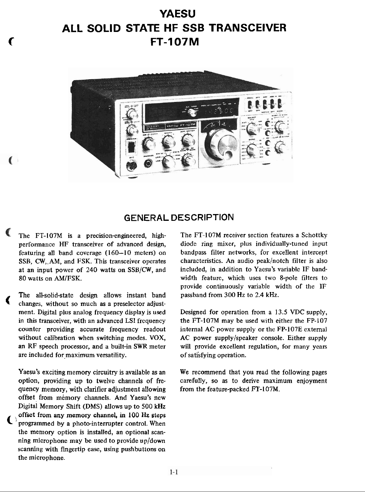
The FT-IO7M is a precision-engineered, highperfomance HF transceiver of advanced design,
featuring al1 band coverage (160-10 meters) on
CW,.AM, and FSK. This transceiver operates
SSB,
at an input power of 240 watts on SSB/CW, and
80 watts on
The all-solid-state design aiiows instant band
C
changes, without so much as a preselector adjustment. Digital plus analog frequency display is used
in this transceiver, with an advanced LSI frequency
counter providing accurate frequency
without calibration when switchiig modes.
an
RF speech processor, and a built-in SWR meter
are included
Yaesu's exciting memory circuitry is available as
option, providing up
quency memory, with clarifier adjustment allowing from the feature-packed FT-107M.
offset from memory channels. And Yaesu's new
Digital Memory Shift
offset from any memory channel, in 100 Hz steps
C
'
programmed by a photo-interrupter control. When
the memory option is installed, an
ning microphone may be used to
scanning with fingertip ease, using pushbuttons on
the microphone.
AMIFSK.
for.maximum versatility.
to
twelve channels of fre-
(DMS) aiiows up to 500 kHz
provide up/down
readout
VOX,
an
optional scan-
The FT-107M receiver section features a Schottky
diode ring mixer, plus individually-tuned input
bandpass filter networks, for excellent intercept
characteristics. An audio
included, in addition to Yaesu's variable IF bandwidth feature, which uses two 8-pole filters to
provide continuously variable width of the IF
passband from 300 Hz to
Designed for operation from a 13.5
FT-IO7M may be used with either the FP-107
the
intemal AC power supply or the FP-107E externa1
AC power
will provide excellent regulation, for many years
of
satisfying opeiation.
We recommend that you read the following pages
carefully, so as to derive maximum enjoyment
supply/speaker console. Either supply
peaklnotch filter is also
2.4
kHz.
VDC
supply,
Page 4
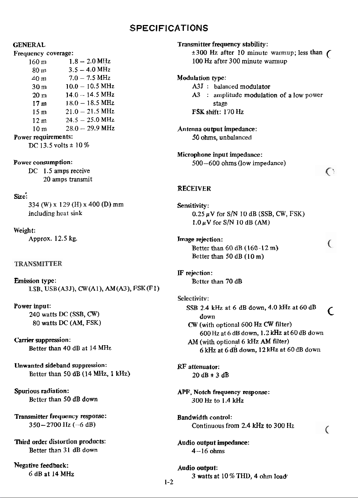
SPECIFICATIONS
GENERAL
Frequency coverage:
160m 1.8 - 2.0 MHz
80
m
40 m
30 m
20 m
17
m
1Sm 21.0 - 21.5 MHz
12m 24.5 - 25.0 MHz
10
m
Power requirements:
DC 13.5 volts t 10
Power consumption:
DC 1.5 amps receive
20 amps transmit
sie:
334
(W)
including heat sink
Weigh t:
Approx. 12.5
3.5 - 4.0 MHz
7.0 - 7.5 MHz
10.0 - 10.5 MHz
14.0 - 14.5 MHz
18.0 - 18.5 MHz
28.0 - 29.9 MHz
x
129 (H) x 400
kg.
%
(D.)
mm
Transmitter frequency stabiiity:
+300 Hz after 10 minute warmup; less than
100 Hz after 300 minute warmup
Modulation type:
A3J : balanced modulator
A3
:
amplitude modulation of a low power
stage
FSK shift: 170 Hz
Antenna output impedance:
50 ohms, unbalanced
Microphone input impedance:
500-600 ohms (low impedance)
RECEIVER
Sensitivity
Image rejection:
:
0.25 pV for S/N 10 dB (SSB,
i.OpV for SIN 10 dB (AM)
Better than 60
Better than 50 dB (10 m)
dB
(160-12
m)
CW,
FSK)
(
Emission type:
LSB, USB(A3J), CW(Al), AM(A3), FSK(F1)
Power input:
240 watts DC (SSB, CW)
80 watts DC
Canier suppression:
Better than 40 dB at 14 MHz
Unwanted sideband suppression:
Better than 50 dB (14
Spurious radiation:
Better than 50 dB down
Transmitter frequency response:
350-2700 Hz (-6
Third
order distortion products:
Better than 3 1 dB down
(AM,
FSK)
MHz, 1 kHz)
dB)
IF
rejection:
Better than 70 dB
SSB 2.4 kHz at 6 dB down, 4.0
down
CW (with optional 600 Hz CW fiter)
600Hz at 6 dB down, 1.2 kHz at 60dB down
AM
(with optional 6 kHz
6
kHz at 6 d~ down, 12
RF
attenuator:
20dBi3dB
APF, Notch frequency response:
300 Hz to 1.4 kHz
Bandwidth control:
Continuous from 2.4 IcHz to 300 Hz
Audio output impedance:
4-16 ohms
AM
kHz
IcHz
at 60 dB
filter)
at 60 dB down
C
Negative feedback:
6 dB at 14 MHz
Audio output:
1-2
3
watts at 10 % THD, 4 ohm loa&
Page 5
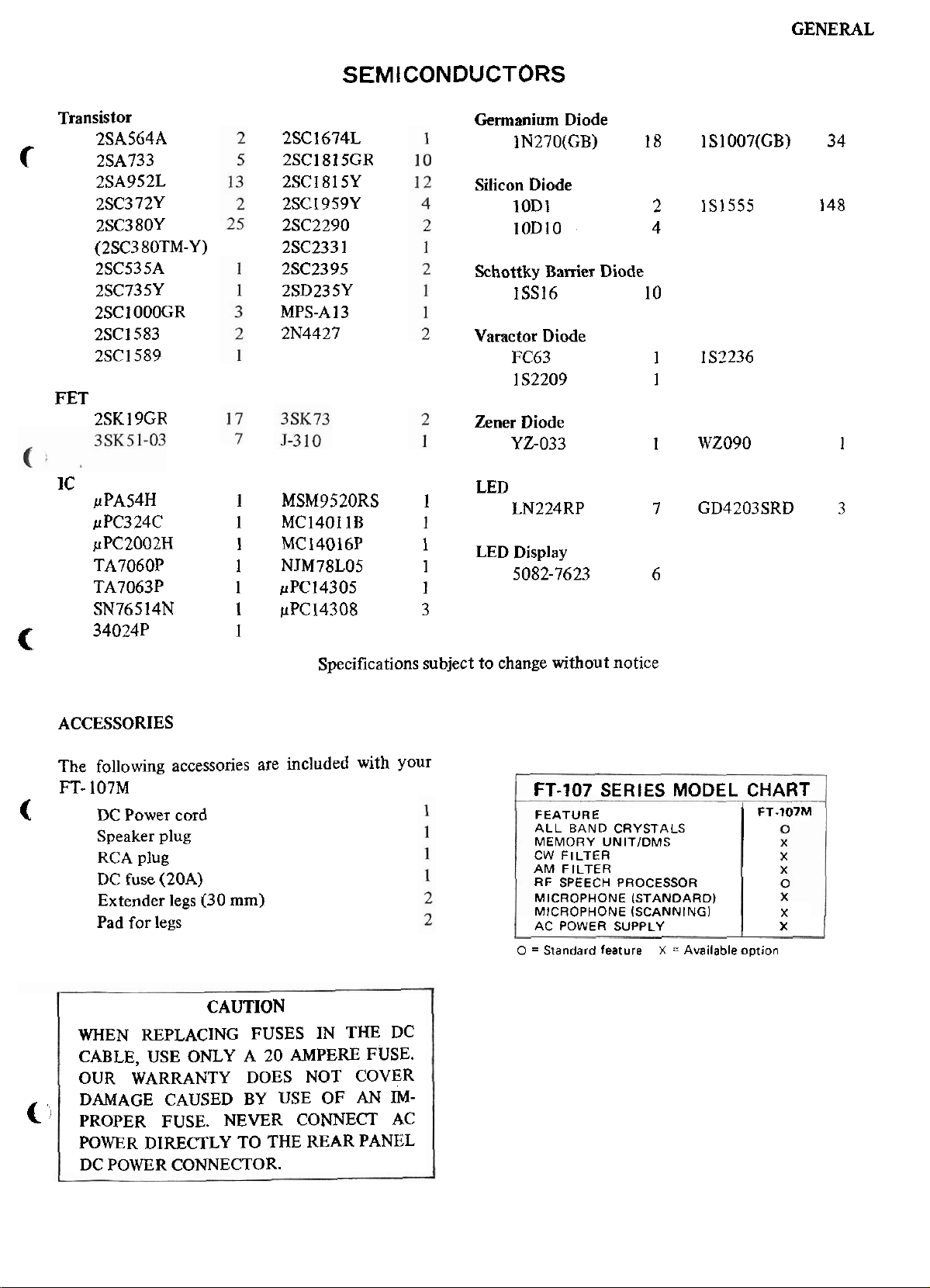
SEMICONDUCTORS
GENERAL
Transistor
2SC1674L
2SC1815GR
2SC1815Y
2SC1959Y
2SC2290
2SC233 1
2SC23 95
2SD235Y
MPS-A 13
2N4427
c
2SA564A
2SA733
2SA952L
2SC3 72Y
2SC38OY
(2SC3 80TM-Y)
2SC535A
2SC735Y
2SC1000GR
2SC1583
2SC1589
FET
2SK 19GR
IC LED
pPA54H 1 MSM9520RS 1
p PC3 24C 1 MC14011B 1
pPC2002H l MC14016P
TA7060P 1 NJM78L05 1
TA7063P 1 pPC14305 1
SN76514N
34024P
I
pPC14308 3
1
c
Specifications subject to change without notice
Germanium
1N270(GB) 18 IS1007(GB) 34
Silicon Diode
10D1
lOD10 4
Schottky Bamer Diode
1SS16 1
Varactor Diode
FC63
l S2209
Zener Diode
YZ-O33 1 WZ090
LN224RP 7 GD4203SRD
l LED Display
5082-7623 6
Diode
2
O
1
1
IS1555 148
l S7236
1
3
ACCESSORIES
The following accessones are included with your
FT-
107M
C
DC
Power cord
Speaker plug
RCA plug
fuse (20A)
DC
Extender legs I30
mm)
Pad for legs
CAUTION
WHEN REPLACING FUSES IN THE DC
CABLE, USE
ONLY A 20
AMPERE
OUR WARRANTY DOES NOT
DAMAGE CAUSED BY USE OF AN
<
'
PROPER FUSE. NEVER CONNEcT AC
POWER DIRECTLY TO THE REAR PANEL
DC POWER CONNECTOR.
FUSE.
COVER
IM-
FT-107
FEATURE FT-107M
ALL BAND CRYSTALS
MEMORY
CW FILTER
AM FILTER
RF SPEECH PROCESSOR
MICROPHONE ISTANDARDI
MICROPHONE
AC POWER SUPPLY
O
=
Standard feature
SERIES
UNITIDMS
(SCANNING]
X
MODEL
=
Availableoption
CHART
X
X
Page 6
FRONT
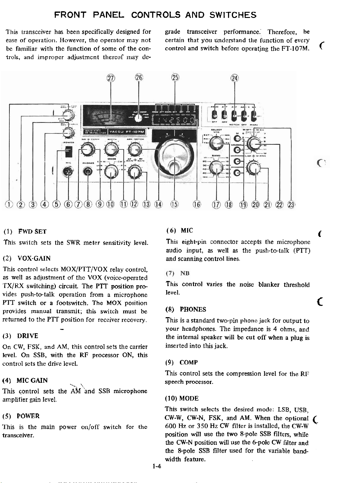
This transceiver has been specifically designed for grade transceiver performance: Therefore, be
ease of operation. However, the operator may not
be familiar with the function of some of the controls, and improper adjustment thereof may de-
PANEL
CONTROLS
certain that you understand the function of every
control and switch before operating the FT-IO7M.
AND
SWITCHES
C
(l) FWDSET
This switch sets the SWR meter sensitivity level.
(2)
VOX-CAIN
This control selects MOX/PTT/VOX relay control,
we11 as adjustment of the VOX (voice-operated
as
TX/RX switching) circuit. The PTT position provides push-tc-talk operation from a microphone
PTT switch or a footswitch. The MOX position
provides manual transmit; this switch must be
returned to the PTT position for receiver recovery.
-
(3) DRIVE
On CW, FSK, and
level. On SSB, with the
control sets the drive
(4)
MIC
GAIN
This control sets the
amplifier gain level.
(5)
POWER
This is the
transceiver.
AM,
this control sets the carrier
RF
processor ON, this
level.
'\
\
AM
and SSB microphone
main power on/off switch for the
(6)
MIC
This eight-pin connector accepts the microphone
andio input, as we11 as the push-to-talk (PTT)
and scanning control lines.
This control vanes the noise blanker threshold
level.
(8)
PHONES
This is a standard twc-pin phone jack for output to
your headphones. The impedance is 4 ohms, and
intemal speaker will
the
inserted into this jack.
(9)
COMP
This control sets the compression
speech processor.
(10)
MODE
This switch selects the
CW-W, CW-N, FSK, and
600
Hr
or 350
position
the CW-N position will use the
the
width feature.
1-4
will use the two 8-pole SSB filters, while
&pole SSB filter used for the variable band-
Hz
be
cut off when a plug
level for the RF
desired mode: LSB, USB,
AM.
When the optional
CW
filter is installed, the CW-W
6-pole
CW
t
c
is
C
filter and
Page 7
GENERAL
(l
l) WIDTH
This control vanes the IF handwidth (except on
AM) from 2.4 kHz down to 600 Hz.
c
12) AF CAIN TX MR The transmit frequency is controlled
This control vanes the audio output level from the
speaker or headphones. Clockwise rotation increases the audio output level.
This control vanes the gain of the receiver RF and
IF
amplifiers. For proper S-meter operation, this
meter should be set
This control vanes the frequency response of the
audio
may be
(I
This is the
transceiver.
(16) ANALOG AND DIGITAL DISPLAYS
The analog display is
with 1 kHz marks providing finer resolution. The
digital display
(17) BAND
This switch selects the
peak/notch filter. The peak/notch filter
varied over the range 300 Hz-1400 Hz.
S)
MAIN TUNING KNOB
main frequency tuning dial for the
fully clockwise.
calibrated every 50 kHz,
provides resolution to 100 Hz.
desired band
RX MR
(19) PUSH SWITCHES (M, M SET, TX CLAR,
RX CLAR)
M Push the M button to store a fre-
M
SFT Push this switch to activate the.
TX
CLAR While using the internal VFO or
RX
CLAR) memory, push the TX CLAR switch to
(20) CLARIFIER
The CLARIFIER allows offset from the VFO
or memory frequency, according to the selection
made by
buttons.
The receive frequency is controlled by
the memory unit and/or DMS, while
the transmit frequency is controlled
by the intemal VFO.
by the memory unit and101 DMS,
while the receive frequency is
trolled by the internal VFO.
quency
DMS system.
provide offset from the TX frequency.
Push the RX CLAR button to
offset of the receive frequency, and
push both buttons to
of the transceive frequency from the
dial frequency.
pushing the TX CLAR and/or RX CLAR
in
memory.
provide offset
con-
provide
(l
8)
SELECT SWITCH
C
This switch selects the means of frequency control
for the transceiver. The
fully equipped FT-107M (DMS unit installed).
The transmit frequency is controlled
by the
(option), while the receive frequency
is controlled
VFO.
The ieceive frequency is controlled by
the FV-107
while the
trolled by the FT-107M internal VFO.
The transceive frequency is controlled
by the FV-107
The transceive frequency is controlled
by the memory unit
(Digital Memory Shift) control.
c
TX EXT
RX
EXT
EXT
I
M R
details below apply to the
FV-107 extemal VFO
by
the
FT-107M
external VFO (option),
transmit frequency is con-
external VFO (option)
and/or the DMS
internal
(21) M FINE
This control allows
operation.
(22) M SET
This control activates the DMS system,
offset tuning from a memory channel in 100 Hz
steps,
The
M
FINE control may, in
between the 100 Hz steps.
tune
(23) M CH
This control selects the
(24) LEVER SWITCHES
PROC
ATT This switch activates a 20 dB attenu-
This switch activates the RF speech
processor.
ator in the incoming signal path.
fme tuning dunng memory
allowing
tum,
be used to
desired memory channel.
Page 8
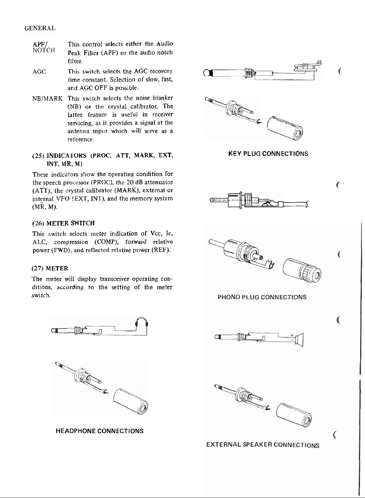
APF/
This control selects either the Audio
Peak Filter (APF) or the audio notch
filter.
AGC
NB/MARK This switch selects the noise blanker
(25) INDICATORS (PROC, ATT, MARK,
INT, MR, M)
These indicators show the operating condition for
the speech processor (PROC), the
(ATT), the crystal calibrator (MARK),
intemal
k.
M).
(26) METER SWITCH
This switch selects meter indication of Vcc, Ic,
ALC, compression (COMP), forward relative
power
This switch selects the
time constant. Selection of slow, fast,
and AGC OFF is possible.
(NB) or the crystal calibrator. The
latter feature is useful in receiver
servicing, as it provides a signal at the
antenna input which will serve as a
reference.
VFO
(EXT,
(FWD),
INT), and the memory system
and reflected relative power
20
AGC
dB
recovery
EXT,
attenuator
external or
(REF).
01
KEY
PLUG
f'-%\
CONNECTIONS
b-
(27) METER
The meter will display transceiver operating con-
ditions, according to the setting
switch.
HEADPHONE CONNECTIONS
of
the meter
Page 9
GENERAL
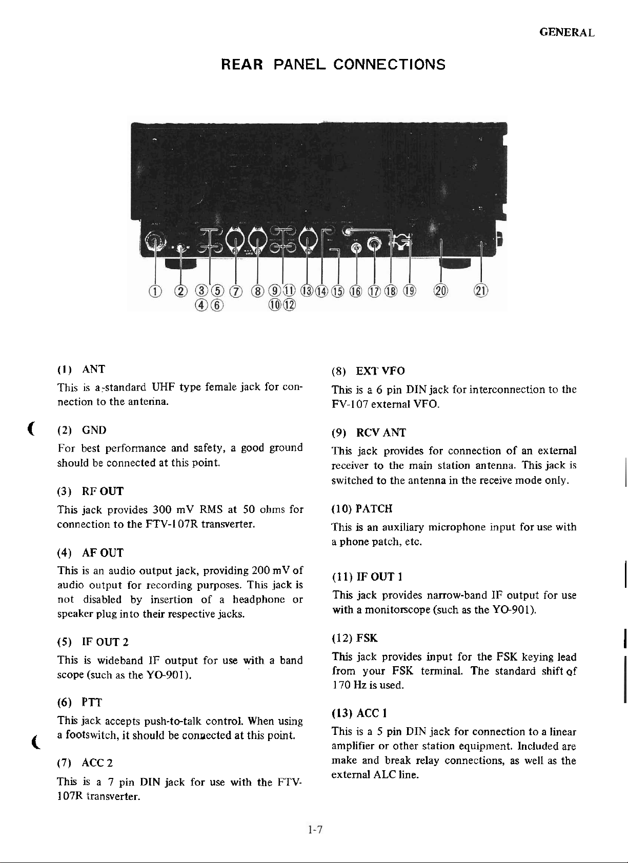
REAR
PANEL CONNECTIONS
(l)
ANT
This is
nection to the antenna.
<
(2) GND
For best performance and safety, a good ground
should be connected at this point.
(3)
This jack
connection to the FTV-I 07R transverter.
(4)
This is an audio output jack, providing 200 mV of
audio output for recording
not
speaker plug
(5)
This is wideband
scope (such as the YO-901).
a:standard UHF type female jack for con-
RFOUT
provides 300 mV
AF OUT
disabled by insertion of a headphone or
into their respective jacks.
IF OUT 2
IF output for use with a band
RMS
at 50 ohms for
purposes. This jack is
(8)
EXTVFO
6
This is a
FV-107
(9)
This
receiver to the main station antenna. This jack is
switched to the antenna in the receive mode
(l
O)
PATCH
is
This
a phone patch, etc.
(l l)
This jack provides narrow-band IF output for use
with a
(1
2)
FSK
This jack
from your FSK terminal. The standard shift of
Hz
170
pin DIN jack for interconnection to the
external VFO.
RCVANT
jack pmvides for connection of an extemal
only.
an auxiliary microphone input for use with
IF OUT 1
monitorscope (such as the YO-901).
provides input for the FSK keying lead
is used.
I
I
(6)
PTT
This jack accepts push-to-talk control. When using
a footswitch, it should be connected at this point.
c
(7) ACC 2
This is a 7 pin DIN jack for use with the
107R transverter.
FTV-
(13) ACC
This is a 5 pin DIN jack for connection to a linear
amplifier or other station equipment. Included are
make and break
external ALC line.
1
relay connections, as we11 as the
Page 10
GENERAL
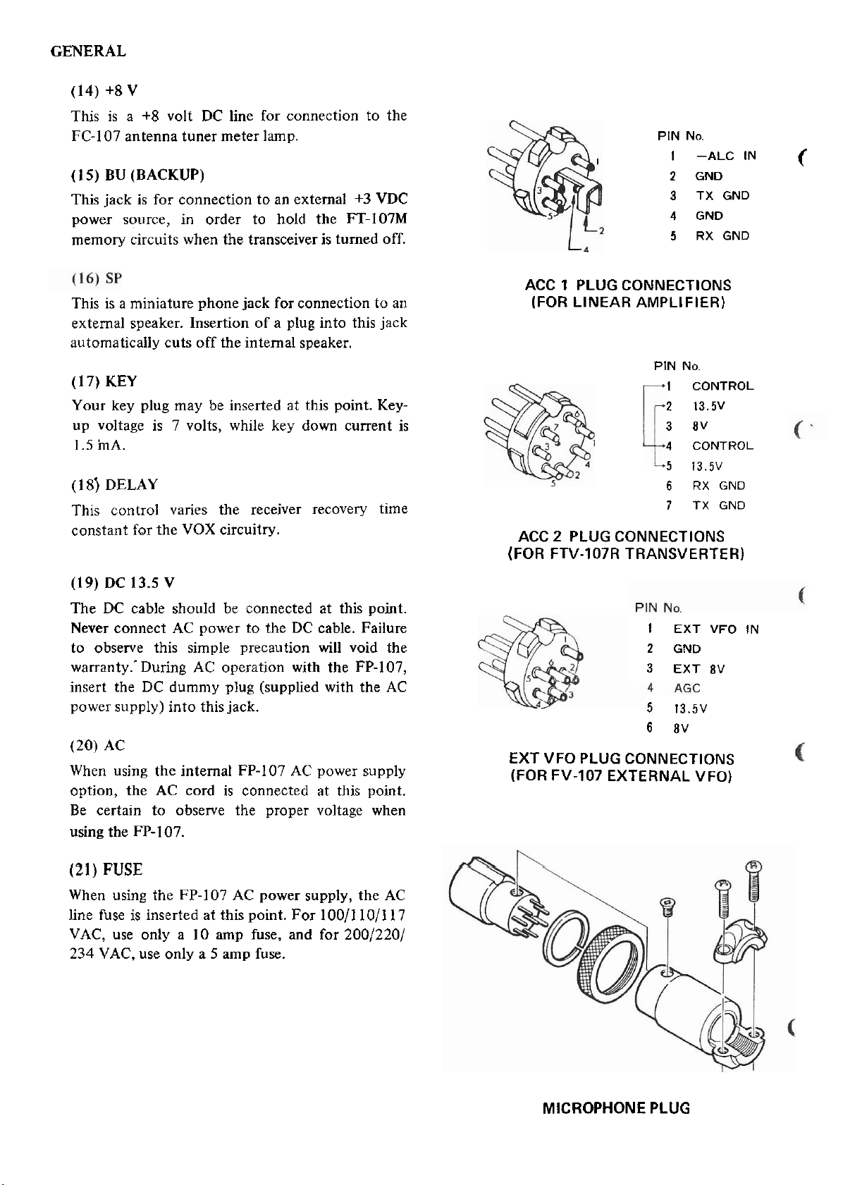
(14)
+8
V
This is a
FC-107 antenna
(1
5)
This jack is for connection to an extemal
+8 volt DC line for connection to the
tuner meter lamp.
BU (BACKUP)
+3
VDC
power source, in order to hold the FT-107M
memory circuits when the transceiver is
tumed off.
This is a miniature phone jack for connection to an
extemal speaker. Insertion of a plug into this jack
automatically
(l
7)
KEY
cuts off the intemal speaker.
Your key plug may be inserted at this point. Key-
up voltage is 7 volts, while key down current is
mA.
1.5
(l
8) DELAY
This control vanes the receiver recovery time
constant
for the VOX circuitry.
PIN No.
I
-ALC
2
GND
3
TX GNO
4
GND
5
RX GND
ACC 1
(FOR
ACC
PLUG
CONNECTIONS
LINEAR AMPLIFIER)
PIN No.
1
2
3
4
5
6
7
2
PLUG
CONNECTIONS
CONTROL
13.5V
BV
CONTROL
13.5V
RX GND
TX GND
(FOR FTV-107R TRANSVERTER)
IN
(
(19)
DC
13.5
V
The DC cable should be connected at this point.
Never connect AC power to the DC cable.
Failure
to observe this simple precaution will void the
warranty..During AC operation with the FP-107,
insert the DC dumniy plug (supplied with the AC
power supply)
(20)
AC
into this jack.
When using the internat FP-107 AC power supply
option, the AC cord is connected at this point.
Be certain to
observe the proper voltage when
using the FP-107.
(21)
FUSE
When using the FP-107 AC power supply, the AC
100/1
line fuse is inserted at this point. For
VAC, use only a
234
VAC, use only a 5 amp fuse.
10
amp fuse,
and
10/117
for 200/220/
EXT VFO
PLUG
(FOR FV-107
I
EXT
VFO
2
GND
3
EXT
BV
5
13.5V
6
BV
CONNECTIONS
EXTERNAL VFO)
IN
MICROPHONE
PLUG
Page 11
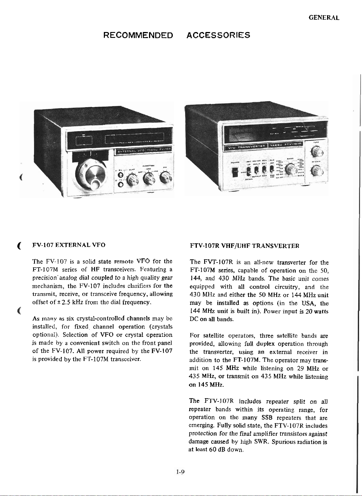
RECOMMENDED ACCESSORIES
GENERAL
(
FV-107 EXTERNAL VFO FTV-107R VHFIUHF TRANSVERTER
The FV-l07 is a solid state remote VFO for the
FT-107M senes of HF transceivers. Featuring a
precision'analog
mechanism, the FV-107 includes clanfiers for the
transmit, receive, or transceive frequency, allowing
offset of
As many as six crystal-controlled channels may be
installed, for
optional). Selection of VFO or crystal operation
is made by a convenient switch on the front panel
of the FV-107. All power required by the FV-107
provided
is
i
dia1 coupled to a high quality gear
2.5
kHz from the dia1 frequency.
fixed, channel operation (crystals
by
the FT-107M transceiver.
The FVT-lO7R is an all-new transverter for the
FT-107M senes, capable of operation on the 50,
144, and 430
equipped with all control circuitry, and the
MHz and either the 50 MHz or 144 MHz unit
430
may be installed as options (in the USA, the
MHz unit is built in). Power input is
144
DC
on all bands.
For satellite operators, three satellite bands are
provided, allowing full duplex operation
the transverter, using an extemal receiver in
addition to the FT-107M. The operator may
mit on 145 MHz while listening on
MHz, or transmit on 435 MHz while listening
435
on 145 MHz.
The FTV-I07R includes repeater split on all
repeater bands within its operating range, for
operation on the
emerging. Fully solid state, the FTV-107R includes
protection for the final
damage caused by high SWR. Spunous radiation is
least 60 dB down.
at
MHz bands. The basic unit comes
many SSB repeaters that are
amplifier transistors against
20
through
29
MHz or
watts
trans-
Page 12
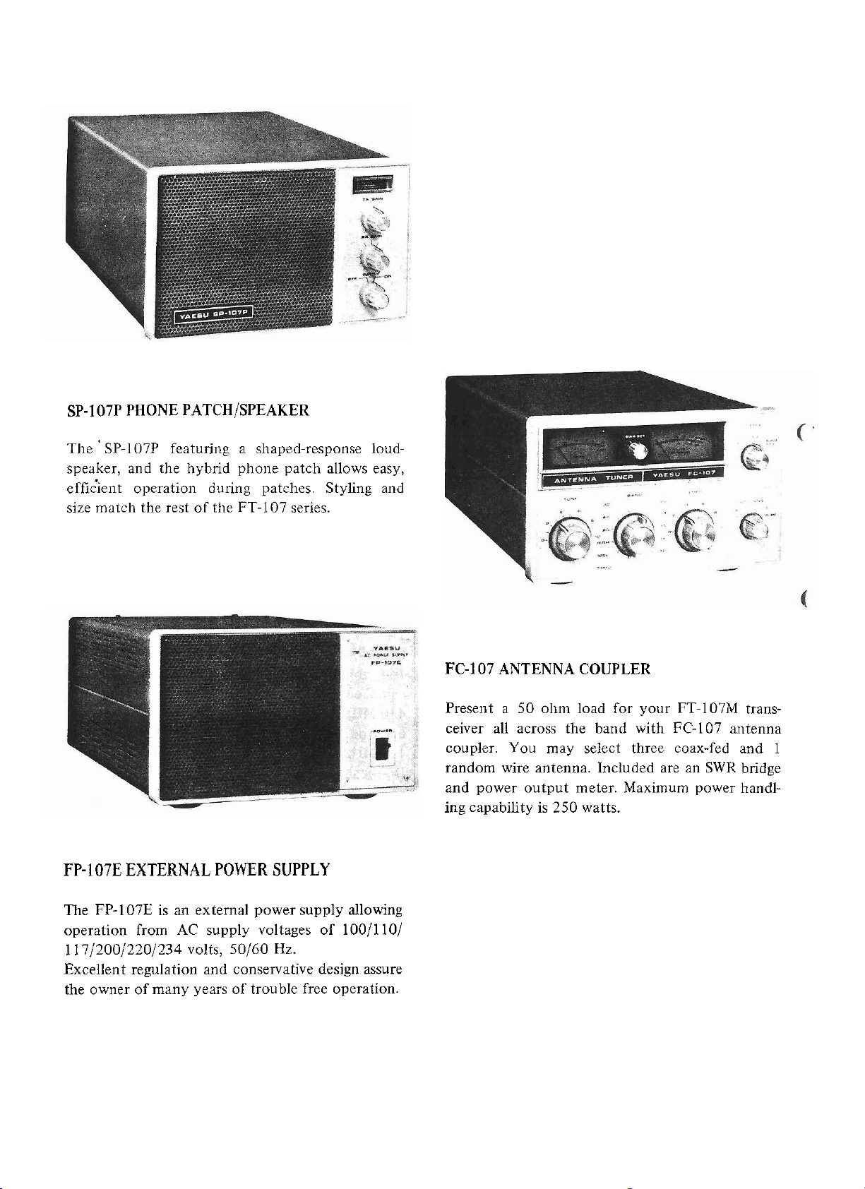
SP-107P PHONE PATCHISPEAKER
Tlie ' SP-107P featuriiig a sliaped-response loudspeaker, and the hybrid phoiie patch allows easy,
effiiient operation during patches. Styling and
size matcli the rest of tlie FT-107 series.
FC-107 ANTENNA COUPLER
Preseiit a 50 olim load for your FT-107M transceiver all across the band with FC-107 alitenna
coupler. You may select three coax-fed and 1
random wire antenna. Included are an SWR bridge
and power output meter. Maximum power handling capability is 250 watts.
FP-107E EXTERNAL POWER SUPPLY
The FP-107E is an external power supply allowing
operation from AC supply voltages of 100/110/
1 17/200/220/234 volts, 50160
Excellent regulation and conservative design assure
the owner of many years of trouble free operation.
Hz.
Page 13
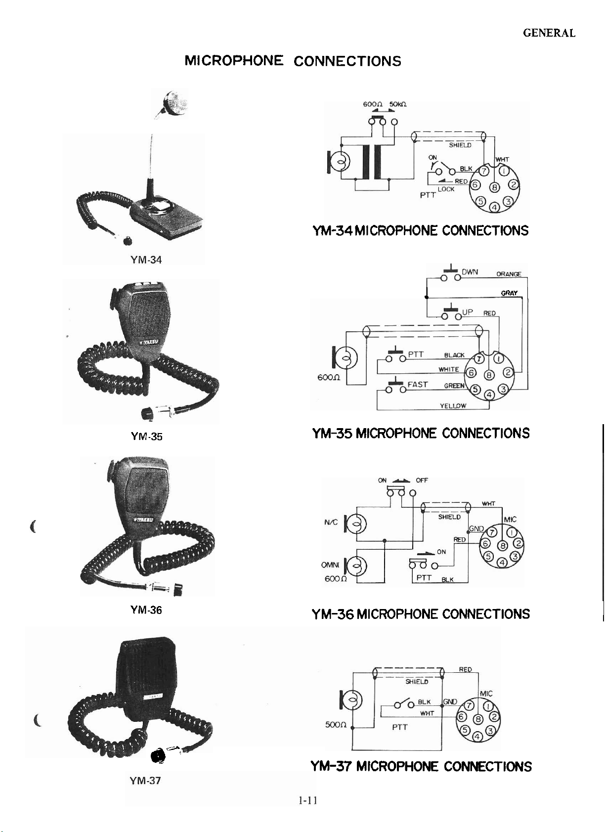
MICROPHONE CONNECTIONS
YM-34 MICROPHONE CONNECTIONS
l
GENERAL
GRAY
,
I
Y
Y
M
M
-35
-36
YM-35 MICROPHONE CONNECTIONS
YM-36 MICROPHONE CONNECTIONS
l
I
d!":
YM-37 MICROPHONE CONNECTIONS
Page 14
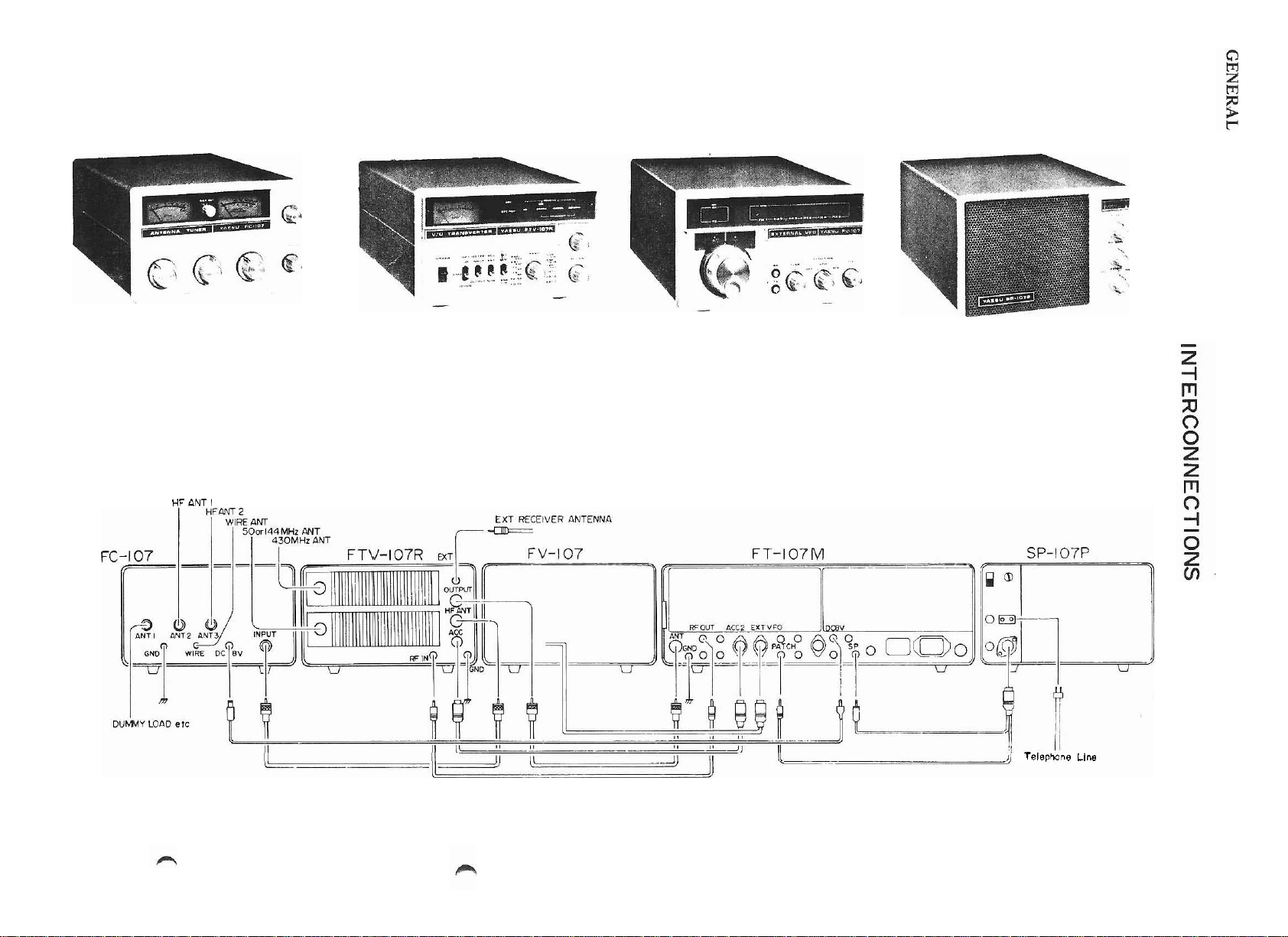
HF
ANT
l
Telephone
Line
Page 15
INSTALLATION: FT- 1 07'M
GENERAL
C
The FT-107M is designed
ceiver for top-performance
operation. For operation from
optional FP-107 intemal power supply or FP-107E
externa1 power supplylspeaker are available from
your Yaesu
tions carefully, so as to understand the important
steps required for a successful installation.
PRELIMINARY INSPECTION
Upori opening the packing carton, immediately
give the transceiver a thorough visual inspection.
Check to see that the
working freely, and inspect the
sigiis of damage. If any dainage
contact the
ddcument the
ing carton and foam packing material for possible
use at a later date.
dealer. Please read the following sec-
shipping company immediately, and
damage completely. Save the pack-
to
be a single-unit trans-
base station or mobile
AC
mains, the
controls and switches are all
cabinet for any
has
been sustained,
supply/speaker console provide this voltage with
excellent regulation.
from your Yaesu
Before attempting operation of the FP-107 or FP-
107E from AC mains, check to see that the voltage
specification on the rear of the sqply matches
local supply voltage. This inspection must be
your
made before applying power to the equipment.
Operation of the FT-107M directly from AC
mains, from
improper fuse shall void the warranty on this
equipment. Likewise, operation of the FP-107
or FP-107E from
improper fuse shall void the warranty.
an
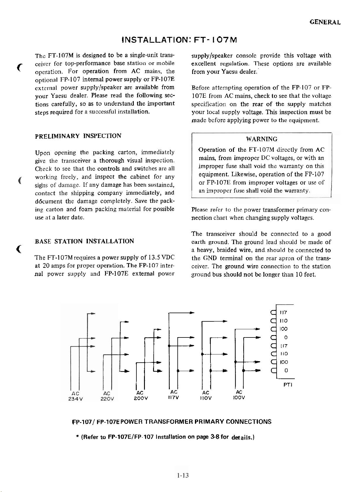
Please refer to the power transfornler primary connectioii chart when changing supply voltages.
improper DC voltages, or with an
These options are available
dealer..
WARNING
improper voltages or iise of
C
BASE STATION INSTALLATION
The FT-107M requires a power supply of
at 20 amps for proper operation. The FP-1 07 internal power supply and FP-107E extemal power
+
+
,IIi--fi:l
+
AC
200V
13.5
VDC
AC
117V
The transceiver should be connected to a good
ground. The ground lead should be made of
earth
a heavy,
the GND terminal on the rear
ceiver. The
ground bus should not be longer than 10 feet.
braided wire, and. should be connected to
apron of the trans-
ground wire connection to the station
t
100
110
PT
I
AC
llOV
AC
IOOV
Fp-1071 FP-107EPOWER TRANSFORMER PRIMARY CONNECTIONS
(Refer to FP-107ElFP-107 Installation
on
page
58for details.)
Page 16
GENERAL
MOBILE INSTALLATION
The FT-107M is designed for operation from 13.5
volts DC, at 20
peaks. As
as a mobile station. The DC cable is a standard
accessory for the
For under-dash mounting, a special mobile mounting bracket is available from your Yaesu dealer.
The FT-107M should be located away from heater
ducts, and a minimum of two inches of air space
on all sides is recommended, in order to allow
proper air flow around the
critical is the area around the heat sink fan exhaust port.
The DC cable comes equipped with a 20 amp fuse
in thé positive line. Use
socket.
When making battery connections, be absolutely
certain to observe the proper polarity of the supply
voltage. cohnect the RED cable lead to the POSITIVE battery terminal, and connect the BLACK
lead to the NEGATIVE battery terminal. Reversed
connections could cause permanent damage to the
transceiver
such,it provides exceptional performance
amps maximum current on voice
FT-I07M.
cabinet. Especially
only a 20 amp fuse in this
Before connecting the DC power cable to the transceiver, check the battery
mnning (battery charging). If the voltage exceeds
15
volts DC, the vehicle voltage regulator should be
so
adjusted,
age to less than 15 VDC. As well, do not operate
the transceiver if the DC supply falls below 12
volts. The transceiver should always be
when the
from possibly causing
circuits of the radio.
ANTENNA CONSIDERATIONS
The FT-I07M is designed for use into a 50 ohm
resistive
50 ohm figure are of no consequence, the
matic fmal protection (AFP) circuitry will reduce
the power output if high SWR conditions are
encountered.
However, your FT-107M AFP circuitry and final
amplifier components are tolerant of the minor
SWR conditions present in
lations. At
rated output power will be obtained.
full
as to limit the maximum charging volt-
car is started, to prevent voltage transients
load. While minor deviations from the
an
SWR of 3:1, for example, 75% of
voltage with the engine
tumed off
damage to the transistor
auto-
many amateur instal-
(
(
CAUTION
OUR
DAMAGE CAUSED BY IMPROPER SUPPLY
CONNECTIONS NOR
BY USE OF AN
It is recommended that the power connections be
made directly to the battery, instead of to the
ignition switch, etc. The battery
able filtering action against ignition noise, while
connection to the ignition switch can place the
power
as short as possible, and keep the lead away from
ignition cables.
Permanent damage will occur if reversed
supply polarity voltage is applied to this transceiver. Our warranty does not cover
caused by reversed supply polarity.
WARRANTY DOES NOT COVER
DAMAGE CAUSED
IMPROPER FUSE.
provides consider-
line
in
a
noisy
circuit.
WARNING
Keep
the
power
damage
cable
The Yaesu RSL senes of mobile
able from yourYaesudealer,fok mobile installations.
1
antennas is avail-
Page 17
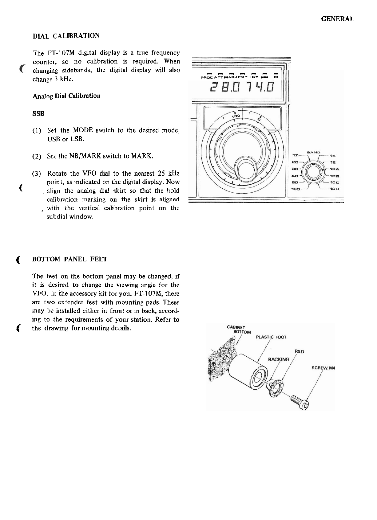
DIAL CALIBRATION
The FT-107M digital display is a true frequency
counter, so no calibration is required. When
changing sidebands, the digital display will also
change 3 kHz.
Analog Dia1 Calibration
SSB
(I) Set the MODE switch to the desired mode,
USB or
LSB.
----Dn=
PIIDCPITMaFIXEXT
INT
Mil
GENERAL
M
Set the NBIMARK switch to
(2)
(3)
Rotate the VFO dia1 to the nearest
MARK.
point, as indicated on the digital display. Now
(
,
align the analog dia1 skirt so that the bold
calibration marking on the skirt is aligned
,
with the vertical calibration point on the
subdial window.
(
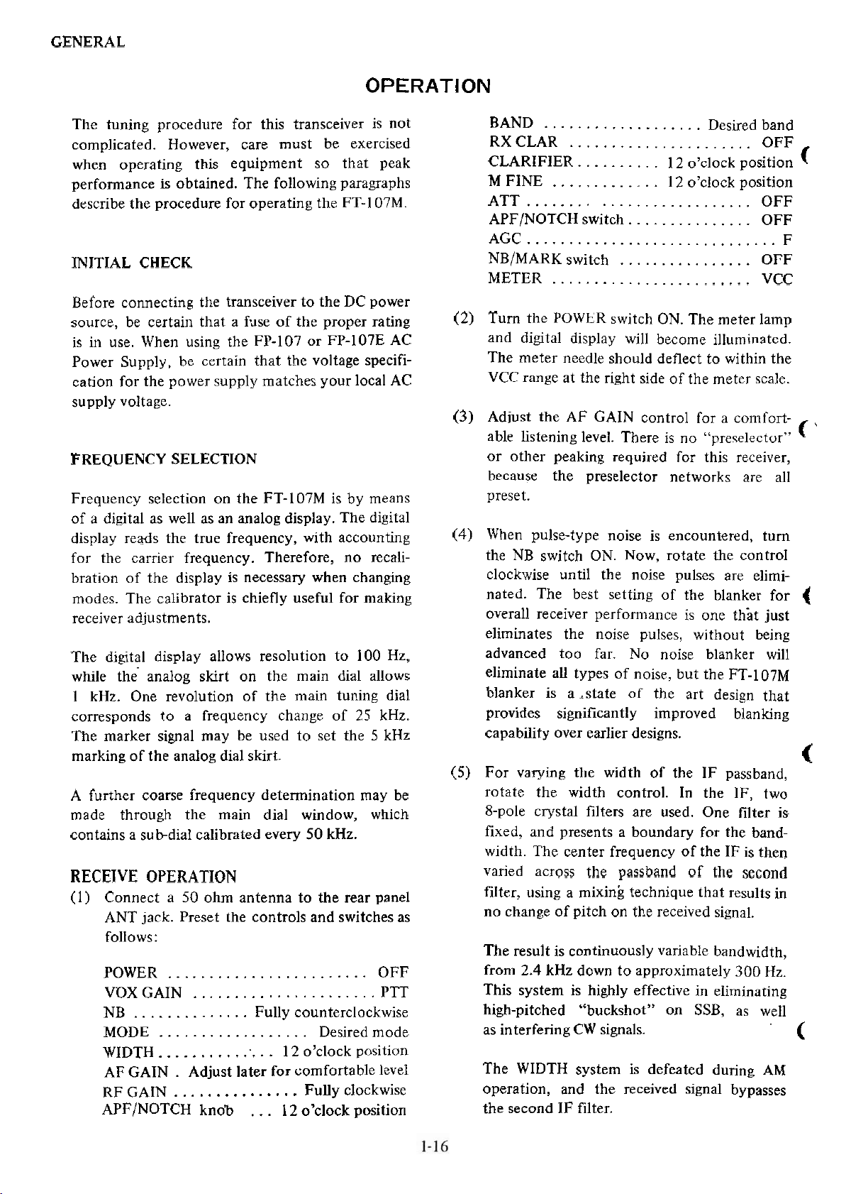
BOTTOM PANEL FEET
The feet on the bottom panel may be changed, if
desired to change the viewing angle for the
it is
VFO. In the
are two
accessory kit for your FT-I07M, there
extender feet with mounting pads. These
may be installed either in front or in back, according to the requirements of your station. Refer
the drawing for mounting details.
(
25
kHz
to
Page 18
GENERAL
OPERATION
The tuning procedure for this transceiver is not
complicated. However, care must be exercised
when operating this equipment so that peak
performance is obtained. The following paragraphs
describe the procedure for operating the FT-I 07M.
INITIAL CHECK
Before connecting the transceiver to the DC power
source, be certaiii that a fuse of the proper rating
is iii use. When
Power Supply, be certain that the voltage specification for the power supply matches your local AC
supply
FREQUENCY SELECTION
Frequency selection on the FT-107M is by means
of a digital as well as an analog display. The digital
display reads the true frequency, with accounting
for
bration of the display is necessary when changuig
modes. The calibrator is chiefly useful for making
receiver adjustments.
The digital display allows resolution to 100 Hz,
while the- analog skirt on the main dial allows
1 kHz. One revolution
corresponds to a frequency change of 25 kHz.
The marker signal may be used to set the 5 kHz
marking of the analog dial skirt.
A further coarse frequency determination may be
made
contains a
RECEIVE OPERATION
(l) Connect a 50 ohm antenna to the rear panel
voltage.
the carrier frequency. Therefore, no recali-
through the main dial window, which
subdial calibrated every 50 kHz.
ANT jack.
follows:
POWER
VDX GAIN
..............
NB
MODE
WIDTH 12 o'clock position
AF GAIN
RF CAIN
APFINOTCH knob
iising the FP-107 or FP-l07E AC
of
the main tuning dial
Preset the controls and switches as
........................
......................
Fully counterclockwise
..................
...............
.
Adjust later for comfortable level
...............
...
Desired mode
Fully clockwise
12 o'clock position
OFF
PTT
BAND
RXCLAR
CLARIFIER
M
ATT
APFINOTCH switch.
AGC
NB/MARK switch
METER
(2) Tum the POWER switch ON. The nieter lamp
and digital display will becoine
The meter needle should deflect to within the
VCC range at the
(3)
Adjust the AF GAIN control for a conifortable listening level. There is no "preselector"
or other peaking required for this receiver,
because the preselector networks are all
preset.
(4)
When pulse-type noise is encountered, tum
the NB switch ON. Now,
clockwise until the noise pulses are
nated. The best setting of the blanker for
overall receiver performance is one tliat just
eliminates the noise
advanced too far. No noise
eliminate all types of noise, but the
blanker is a ,state of the art design that
provides significantly improved blanking
capability over earlier designs.
(5) For varying the width of the IF passband,
rotate the width control. In the IF, two
8-pole
fixed, and presents a boundary for the band-
width. The center frequency of the IF is then
varied across
filter, using a mixing technique that results in
no
The result is continuously variable bandwidth,
from 2.4
This system is highly effective in eliminating
high-pitched "buckshot" on SSB, as
as interfenng CW signals.
The WIDTH system is defeated during AM
operation, and the received signal
the second IF filter.
...................
Desired band
......................
FINE
..........
.............
12 o'clock position
12 o'clock position
..........................
..............
..............................
................
........................
illuii~inated.
right side of the meter scale.
rotate the control
pulses, without being
blanker will
FT-107M
crystal filters are used. One filter is
the
passband
change of pitch
kHz down to approximately 300
on
the received signal.
nf
thc
OFF
OFF
OFF
OFF
VCC
elimi-
scsnnd
Hz.
well
bypasses
F
t
(
f
'
(
t
Page 19

GENERAL
c
f
(6)
Under conditions of very heavy QRM, while
operating CW, the APF (Audio Peak Filter)
may be activated. Switch the APFINOTCH
lever to APF, and tune the APFINOTCH
control for maximum enhancement of the
desired signal. The operator will observe that
the background noise will be reduced
draniatically,
ratio.
noise
(7)
For elimination of an interfering carrier
witliin the AF passband, set the
switch to NOTCH. Then rotate the APF/
NOTCH coiitrol carefully for the best nulling
of the offending carrier. The notch is
extremely sharp, so
excellent
in
elimiilating interference.
The S-meter still indicates the interfering
'
carrier strength regardless of notching, because the notching action is done in the audio
stage.
(8)
The RX CLARIFIER may be used if
the incoming signal is drifting. Press
the RX CLAR button, and rotate the
CLARIFIER control, to activate the receiver
offset
to allow offset of the transmit frequency, and
bot11 the TX and RX buttons may be pushed
together to allow offsetting of the transceive
frequency from the
tuning. The TX button may be pushed
resulting in excellent signal to
APFINOTCH
tuning is critical, but the
notch depth is extremely effective
dial frequency.
TRANSMITTER OPERATION
The
FT-I07M
requiring
switches. No
initial
level, is required.
When transmitting, it is important that you always
have a dummy
to the antenna jack. The automatic final protection
unit will reduce power if an
connected.
When transmitting, never change the position of
the MODE, BAND, nor the SELECT switch. It
is possible for the final amplifier transistors to be
damaged by transients generated by this kind of
abuse. Please
fail.
The FT-107M contains a heat-sensing protection
circuit for
full power (e.g. key-down CW) for more than 30
seconds. If you have keyed down for a 30
secoiid period, we recommend two minutes of
standby operation to allow the final transistors to
recover to normal operating temperature.
The following paragraphs describe transmitter
operation. If our
107M will provide many years of trouble-free
operation.
setting of the mic gain and RF processor
transmitter is extremely easy to use,
only presetting of the controls and
tuning procedure, other than an
load or matched antenna connected
improper load is
follow this simple precaution without
the final amplifier. Do not transmit at
guidelines are followed, the FT-
(9)
(
AGC time constant setting may be accomplished by setting the AGC switch for the
desired recovery time, slow or fast. The AGC
systeni may also be defeated by setting this
switch to OFF.
(10) For extremely strong signals, a 20 dB attenu-
ator may switched into the incoming receive
line. Set the
purpose.
ATT
switch to ON for this
PRELIMINARY CaECKS
(1) Preset the controls and switches as follows:
VOX GAIN
FWD SET
MIC GAIN
DRIVE
COMP
MODE
DIAL
BAND
SELECl..
TXCLAR..
PROC..
METER switch
(2) Connect a matched antenna to the antenna
jack.
(3)
Set the VOX GAIN control to MOX.
...............
............
........
...........
............
Fully counterclockwise
Fully counterciockwise
Fully counterclockwise
PTT position
12 o'clock position
..........................
................
...................
Desired frequency
Desired band
......................
.....................
........................
.....................
FSK
VFO
OFF
OFF
IC
.
Page 20

GENERAL
(4)
Advance the DRIVE control so that the 1C
reading on the meter reaches exactly 10
amperes.
(5) Set the METER switch to FWD, and adjust
the FWD SET control so that the meter
needle is aligned with the FWD SET position
on the meter scale.
(6)
Set the METER switch to REF. The meter
needle should be within the REF scale area
for full power operation. The REF area
covers SWR
which will
in power output. If the needle rests above
the REF area, remedial work on your antenna
system may be in order. Alternatively, the
FC-107 Antenna Coupler may be used to
provide a 50 ohm load for your transceiver.
(7). For the above test procedure, please be sure
to check the frequency before transrnitting.
Also, use the minimum power necessary to
obtain a full scale
step. If less than 10
this reading, by all means use the lower power
level.
SSB OPERATION
readings of up to
result in essentially no reduction
reading on the FWD SET
amps of 1C will provide
2 : 1, the area
the COMP control to the 10 o'clock position,
and
adjust the DRIVE control so that the
ALC meter needle does not go beyond the
range of the meter. Now adjust the
ALC
COMP control with the meter switch set to
COMP; the meter should indicate between
and 10 on the COMP scale during voice peak
coiiditions.
While some initial adjustment of the MIC
GAIN, COMP, and DRIVE control may be
required, be careful not to
mitter, for best spectral purity.
ing into the microphone in a long syllable
(such as the word "four"), do not advance
the DRIVE control beyond the
the IC or forward power
increase
(5)
To set the VOX circuitry, advance the VOX
GAIN control on the front panel so that your
voice activates the transmitter. The rear panel
DELAY control will
the VOX time constant for the
after you have finished speaking. The
time
ANTITRIP control,
IF Unit, and it
to prevent the speaker output from activating
the VOX. Do not use more VOX GAIN nor
ANTITRIP than necessary.
may be adjusted as necessary
overdive the trans-
hen
point where
reading ceases to.
allow the operator to set
desired hang
VR4003, is located on the
(
5
I
speak-
(
(1) Connect your microphone to the front panel
MIC jack.
(2) Preset the controls and switches as follows:
MODE
METER switch
MIC GAIN
DRIVE
(3)
Close the microphone PTT switch, and speak
into the microphone in a normal voice. Adjust
the MIC GAIN control so that the ALC meter
needle does not go beyond the ALC range of
the meter. With the meter switch set to IC,
the
Samps, or about 113 to 112 of the full power
single-tone meter
(4) To adjust the RF speech processor, place the
PROC switch ON. Speak
in a normal voice, and do not
CAIN setting performed in step (3). Advance
........
...........
...............
reading on voice peaks will be roughly
Desired mode, LSB or USB
...................
10 o'clock position
Set for full output
reading.
into the microphone
change the MIC
ALC
CW
OPERATION
(l) Insert your key plug into the rear panel KEY
jack. Key up
current is 1.5
keyers will work without modification with
FT-107M.
the
(2) If you use a footwitch, connect its plug to
the rear
Set the MODE switch to
(3)
set the VOX GAIN control to PTT.
(4) Activate the transmitter (close the footswitch
or set the VOX GAIN control to MOX), and
go key down. Adjust the DRIVE control fort
the desired power input, up to a maximum
reading of about 18A on the IC meter.
voltage is 7 VDC, and key-down
mA, so most all electronic
apron
PTT
jack.
CW-W
or CW-N, and
Page 21

(5)
For semi-break-in operation, advance the
VOX GAIN control to the point where the
VOX relay is activated by the sidetone audio
signal. The DELAY control,
rear panel,
VOX relay hang time.
(6)
For QRP operation, reduce the level set by
the DRIVE control. The power output may
be reduced to
FSK OPERATION
The FT-107M is designed for 170
ation.
may be adjusted to control the
O
watts, if desired.
located on the
Hz
FSK oper-
SELECT SWITCHESIMEMORY OPERATION
(Note: The memory unit is an available option
for the
Frequency control on the FT-107M is by means of
the
an
combinations of the
will determine the circuitry in control of each
mode, and the selection procedure is descnbed
below:
VFO This positioii selects TX/RX oper-
FT-I07M)
internal VFO, the memory and DMS circuitry,
external VFO (such as the FV-107), or vanous
three. The SELECT switch
ation on the FT-107M internal
VFO.
(l) Connect tlie lead from your terminal unit to
f
the rear panel FSK jack.
(2)
Set the
VOX GAIN control to MOX. Advance the
DRIVE control for a
tlie 1C meter. Do not operate the FT-107M
oii FSK at the same power levels as stipulated
in the sections regarding SSB and CW
ation
(3)
The keying signal from your terminal will
now activate
using the optional CW filter, the CW filter
wili automatically be selected
operation.
AM OPERATION
(1) Set the MODE switch to AM, the METER
switch to
DRIVE controls fully counterclockwise.
(2)
Close the microphone
vcliice the DRIVE control until the reading
on the IC meter reaches S amps.
MODE
]C,
switch to FSK, and set the
reading of 5 anips on
the FT-I07M transmitter. When
dunng FSK
and rotate the
MIG
PTT
switch, and ad=
oper-
GAIN
alid
MR
RX MR
TX MR
EXT
RX EXT
TX EXT
In addition, changing of and offset from memory
channels is controlled from the front panel. The
controls of interest are as follows:
M
M SFT
This position selects TX/RX operation on the FT-107M memory
system.
This position selects RX operation
on the
on
This operation selects TX operation
oii the memory, with RX operation
on the FT-107M
This position selects TX/RX operation on the FV-107 extemal VFO.
This position selects RX operation
on the FV-107, with TX operation
on the
This position selects TX operation
on the FV-107, with RX operation
on the
This button is used to store a fre-
quency
This button activates the DMS circuit.
ineniory, with TX operation
tlie FT-107M internal VFO.
internal VFO.
FT-I07M internal VFO.
FT-107M internal VFO.
in
memory.
c
(3)
Speak into the microphone in a normal voice,
alid advance the MIC GAIN control until a
slight downward deflection of the IC meter
is noted on voice peaks. Do not advance the
MIC
CAIN control too far, as any excess
energy above that required for full modu- or memory operation.
lation will be wasted in spurious emissions.
(4)
In the AM mode, the RF speech processor
and variable IF bandwidth control are not
usable. 1-19
RX CLAR
TX CLAR
T/R CLAR
This button selects offset tuning of
the receive frequency during VFO
or mernory operation.
This button selects offset tuning of
the transmit frequency during VFO
When both buttons are pushed, offset tuning of the transceive fre-
.quency is provided.
Page 22

GENERAL
M FINE The memory fine tuning control
provides a very fine tuning adjustment for memory channels. The
available offset range is
mately 500 Hz, making this contro1 ideal for tuning between the
100 Hz DMS steps.
M SFT The Digital Memory Shift (DMS)
(knob) circuitry is controlled by the M
SFT knob. When a memory
is programmed, and the M SFT
button is
quency can be shifted up or down
in 100 Hz steps, up to and slightly
beyond the 500 kHz limits of the
normal VFO range.
M CH The memory channel selector
chooses the
nel.
TYPICAL MEMORY OPERATION
0peration:of the meinory system and DMS circuitry is perhaps best described by the use of several
examples. Following the
programming techniques will be discussed.
(1)
You are operatiiig on a net on 3970 kHz and
must QSY down
traffic. With the SELECT switch set to VFO,
the main tuning dia1 to 3970 kHz. Press
set
M
to memorize 3970 kHz in the desired
memory channel. Now move the main dial
down to 3960 kHz to handle the message.
When finished, set the SELECT switch to
for instant return to 3970 kHz, the net fre-
quency. For retum to 3960 kHz, again select
VFO.
pushed, the memory fre-
desired memory clian-
exainples, soine advanced
10 kHz to handle a piece of
approxi-
channel
MR
If DXIDX starts to drift, press the RX CLAR
button, and usc the clarifier. Alternatively,
for
slight dnfting, use the M FINE control.
If DXIDX
M
SFT button, and rotate the M SFT control
to the new frequency (e.g. 7080 kHz). The
M
SFT control will not affect the transrnit
frequency, because the SELECT switch is
set to RX MR, and control of the
frequency is by the VFO.
(3) You find DXIDX oii 21270 kHz, working
stations by order of call area. You
DXOAA on 14145 kHz, listening oii 14205
kHz, also by call area. The meinory and no
tune-up capability make this situation easy
to cover.
First, tuiie to 21 270 kHz oii the VFO. set the
M CH switch to 1, and press
handswitch to
kHz. Set the M CH switch to 2. aiid press M.
Now movc the
To check DXgAA's frequency (14145 kHz),
set the SELECT switch to RX MR. To check
DXIDX's frequency, set the bandswitch to
21 MHz and the M CH switch to 1.
is acknowledging your call area, set the
SELECT switch to
check DXOAA, set the bandswitch to 14 MHz,
and the M CH switch to 2.
ing for your call area, switch to RX MR for
RX on 14145
Because there is no "preselector tuning" con-
trol, nor any transmitter peaking whatsoever,
it may be seen that several stations on differ-
ent
bands
qeconds, without toucliing a VFO dial.
decides to QSY 10 kHz, press the
transmit
also find
M.
Now. set the
14 MHz, and the dia1 to 14145
main dial to 14205 kHz.
If
DXl
DX
MR
and call him. To re-
If
DXOAA is listen-
Hz and TX on 14205 kHz.
may
be checked in a niatter
~f
f1
(
L
t
<
(2) You are operating split frequency on
phone, and you hear DXIDX on7090 kHz,
listening for calls on 7205 kHz. With the
SELECT switch on VFO, tune to 7090
and press M to store that frequency in channel 1. Now tum the main dial to 7205 kHz,
and set the SELECT switch to RX MR; you
will now be listening on 7090
transmitting on
pile-up of stations on 7205
DXIDX, set the SELECT switch to VFO;
you will now be listening on 7205
7205
kHz. To listen to the
kHz, while
kHz calling
kHz.
40meter
kHz,
Page 23

GENERAL
NMES ON DMS OPERATION
The DMS control will allow offsetting of the
meniory frequency in 100 Hz steps. Every several
steps. however, a
memory frequency may be
a
relocking of the memory circuitry during shift
by
operation,
lasts
queiicy stability whatsoever will result on tliat
.z
step". The design technique that produces the
briel' "cliirp" also ensures cleaii local oscillator
operation, important for good
tlie receiver.
Wlieii you turn on the M SFT buttoii, perform a
sliiTt ~isiiig the
huttoii OFF, the memory will return to the
original ineinory frequency. Howevcr, wlien you
INISII
rrpirii to the previous sliift frequeiicy; you will
start oii the oripiiial riieinory frequency, and a
iiew sliift must be prograinmed. An alternative
soliitioii is sliown in the "Advanced Programrning
of Memory
Wlicii usiiip the M SFT control, it will frequeiitly
(
useful to use the M FINE control for tuning
be
betweeii the 100 Hz steps, especially on CW. The
M
FINE control should, otlierwise, be set to the
l I o'clock position. Wheii a frequency is stored
iii nieniory. theii recalled, tlie M FINE control
sliifts the inemory frequency based on the position
of tlie M FINE control at tlie time of frequency
(
entry. Therefore, one can see that the offset
capability of tlie
iii1
is iiot preset to the
ADVANCED PROGRAMMING OF MEMORY
CHANNELS
The parallel storage systeiii used in. the FT-107M
niemory allows a degree of flexibility not found in
other nieniory systems: the ability to program a
new memory frequency
memory frequency. An
this teclinique can be used to good advantage.
and it is entirely normal. The "chirp"
only a small fraction of a second, and no fre-
the M SFT buttoii on again, you will not
Chaiinels" sectioii, below.
slight momentary "chirp" in the
observed. This is caused
dynamic range of
IL1
SFT knob, then tuni the M SFT
M
FINE control will be reduced
12
o'clock position.
having shifted an earlier
exaiilple will show how
t
Let us say that DXgAA is traiisiiiitting on 14195
kHz, tuning between 14225 and 14250 kHz;
watchiiig DXgAA's operating practice, you notice
that he listens for stations at
in the above range. Here's how to proceed:
5
kHz intervals with-
Tune the maiii dial to 14195 kHz, set the M CH
switch to 1, and push M. Now set the SELECT
M
switch to RX MR, and press the
Rotate the M SFT knob until you find-the station
DXOAA is working on 14225 kHz (check the transmit frequency of DXQAA instantly by switching
the SELECT switch to VFO to
M
sequence). Now set the
press M. If
14230
frequency, set the M CH switch to 3, and press
M. Follow this sequence until you have
favored listening frequencies in meniory. Now you
can switch to TX MR, tum M SFT OFF. and
select the memory channel corresponding to the
likely listening frequency for DXgAA, be-
most
cause 14225 kHz, 14230 kHz, 14235 kHz, etc.
will all have been
channels. Use the traiismit clarifier, if desired,
to make a minor change in a frequeiicy.
You riiay coiitinue to shift off of any ineinory
cliaiinel, and use it to program a new memory
channel, up to the limit of 12 total memory
channels. This teclinique can
advantage when operating ou a uet, if you
want to store and check several frequeiicies
witliout
SCANNING OPERATION WITH
PHONE (OPTION)
The YM-35 scanning microphone (option) can be
used to
scanning speed control, for coiivenient operation.
The YM-35 can
equipped
memory system for its scanning capability.
First, program any meniory frequency as a starting
poiiit. Now set the M SET button to ON, and press
the UP or DN scanning button on the YM-35. For
long as you hold the UP or DN switch down,
as
scanning will occur. Release the scanning switch to
stop tlie scan.
To activate the fast scanning feature, press both
UP
the
both switches for
the next QSO is with a station .on
kHz, rotate the M SFT knob again to that
stored in successive nieniory
leaving the net frequency (on the VFO).
provide up/down scanning, as well as
only be used with a memory-
FT-107M, because it depends on the
or DN switch and the FAST switch. Release
stopping of the scan.
CH switch to 2, and
SFT button.
follow the calling
DXgAA's
also be used to
YM-35
MICRO-
Page 24

Page 25

Page 26

Page 27

Page 28

Page 29

Page 30

Page 31

Page 32

Page 33

Page 34

Page 35

Page 36

Page 37

Page 38

Page 39

Page 40

Page 41

Page 42

Page 43

Page 44

Page 45

Page 46

Page 47

Page 48

Page 49

Page 50

Page 51

Page 52

Page 53

Page 54

Page 55

Page 56

Page 57
Page 58

Page 59

 Loading...