

Page 1
INSTRUCTION MANUAL
AC5657C
G&L Pumps Series A-C 9100
Base Mounted Centrifugal
Pumps
Page 2

Page 3

Table of Contents
1 Introduction and Safety..............................................................................................................3
1.1 Introduction.......................................................................................................................... 3
1.2 Safety..................................................................................................................................... 3
1.2.1 Safety terminology and symbols.................................................................................3
1.2.2 Safety instruction decals.............................................................................................. 4
1.3 User safety.............................................................................................................................5
1.3.1 Wash the skin and eyes................................................................................................6
1.4 Protecting the environment................................................................................................6
2 Transportation and Storage...................................................................................................... 7
2.1 Examine the delivery........................................................................................................... 7
2.1.1 Examine the package................................................................................................... 7
2.1.2 Examine the unit............................................................................................................7
2.2 Safe handling requirements............................................................................................... 7
2.3 Storage requirements....................................................................................................... 10
Table of Contents
3 Product Description................................................................................................................. 11
3.1 General description...........................................................................................................11
3.2 Operational specifications................................................................................................11
3.3 Nameplate information.....................................................................................................11
4 Installation................................................................................................................................. 13
4.1 Preinstallation.....................................................................................................................13
4.1.1 Pump location guidelines..........................................................................................13
4.1.2 Typical installation...................................................................................................... 14
4.1.3 Foundation requirements..........................................................................................14
4.1.4 Level the base on a concrete foundation ............................................................... 15
4.1.5 Grout the baseplate....................................................................................................15
4.2 Coupling alignment...........................................................................................................16
4.2.1 Prepare for alignment................................................................................................ 16
4.2.2 Align the pump using a straight edge and calipers...............................................16
4.2.3 Align the pump using a dial indicator......................................................................18
4.2.4 Final alignment............................................................................................................19
4.2.5 Optional alignment procedure.................................................................................19
4.2.6 Dowel the pump and driving unit.............................................................................19
4.2.7 Coupler limitations..................................................................................................... 19
4.3 Piping checklists.................................................................................................................19
4.3.1 Piping checklist........................................................................................................... 19
4.3.2 Suction piping checklist.............................................................................................20
5 Commissioning, Startup, Operation, and Shutdown.......................................................... 23
5.1 Preparation for startup...................................................................................................... 23
5.1.1 Pre-start checks........................................................................................................... 23
5.1.2 Priming.........................................................................................................................24
5.1.3 Starting.........................................................................................................................24
5.1.4 Operating checks....................................................................................................... 24
5.1.5 Check the rotation...................................................................................................... 24
5.1.6 Freezing protection.................................................................................................... 25
5.1.7 Change the rotation................................................................................................... 25
G&L Pumps Series A-C 9100 Base Mounted Centrifugal Pumps INSTRUCTION MANUAL 1
Page 4

Table of Contents
6 Maintenance..............................................................................................................................27
6.1 Maintenance schedule...................................................................................................... 27
6.2 Flood-damaged pumps....................................................................................................28
6.3 Bearing maintenance........................................................................................................ 28
6.3.1 Regrease the grease-lubricated bearings............................................................... 29
6.3.2 Lubricating grease requirements............................................................................. 30
6.4 Shaft-seal maintenance..................................................................................................... 30
6.4.1 Mechanical seal maintenance................................................................................... 30
6.4.2 Packed stuffing box maintenance............................................................................ 31
6.5 Cleaning without dismantling the pump........................................................................ 31
6.6 Disassembly........................................................................................................................31
6.6.1 Disassembly precautions...........................................................................................31
6.6.2 Drain the pump...........................................................................................................32
6.6.3 Remove the hex coupling guard.............................................................................. 32
6.6.4 Disassemble the pump with packing on shaft sleeve............................................ 33
6.7 Pre-assembly inspections................................................................................................. 34
6.7.1 Replacement guidelines............................................................................................ 34
6.7.2 Shaft and sleeve inspection.......................................................................................34
6.8 Dimensions......................................................................................................................... 35
6.9 Reassembly.........................................................................................................................35
6.9.1 Reassemble the pump with the mechanical seals on the shaft sleeve................ 35
6.9.2 Reassemble the pump with the packing on the shaft sleeve................................38
6.9.3 Install the hex coupling guard...................................................................................41
6.9.4 Adjustable wear rings................................................................................................ 41
6.9.5 Install the oil ring.........................................................................................................42
6.9.6 Change the oil for oil lubricated bearings...............................................................42
6.9.7 Limited end float coupling........................................................................................ 43
6.9.8 Assembly references.................................................................................................. 43
7 Troubleshooting....................................................................................................................... 45
7.1 Operation troubleshooting.............................................................................................. 45
8 Parts Listings and Cross-Sectional Drawings........................................................................49
8.1 Parts list............................................................................................................................... 49
9 Product warranty...................................................................................................................... 52
2 G&L Pumps Series A-C 9100 Base Mounted Centrifugal Pumps INSTRUCTION MANUAL
Page 5
1 Introduction and Safety
1.1 Introduction
Purpose of this manual
The purpose of this manual is to provide necessary information for:
• Installation
• Operation
• Maintenance
CAUTION:
Read this manual carefully before installing and using the product. Improper use of the
product can cause personal injury and damage to property, and may void the warranty.
NOTICE:
Save this manual for future reference, and keep it readily available at the location of the
unit.
1 Introduction and Safety
1.2 Safety
WARNING:
• The operator must be aware of safety precautions to prevent physical injury.
• Operating, installing, or maintaining the unit in any way that is not covered in this
manual could cause death, serious personal injury, or damage to the equipment. This
includes any modification to the equipment or use of parts not provided by Xylem. If
there is a question regarding the intended use of the equipment, please contact a
Xylem representative before proceeding.
• Do not change the service application without the approval of an authorized Xylem
representative.
CAUTION:
You must observe the instructions contained in this manual. Failure to do so could result
in physical injury, damage, or delays.
1.2.1 Safety terminology and symbols
About safety messages
It is extremely important that you read, understand, and follow the safety messages and
regulations carefully before handling the product. They are published to help prevent
these hazards:
• Personal accidents and health problems
• Damage to the product and its surroundings
• Product malfunction
Hazard levels
Hazard level Indication
G&L Pumps Series A-C 9100 Base Mounted Centrifugal Pumps INSTRUCTION MANUAL 3
DANGER:
A hazardous situation which, if not avoided, will result in
death or serious injury
Page 6
1 Introduction and Safety
Hazard level Indication
WARNING:
A hazardous situation which, if not avoided, could result
in death or serious injury
NOTICE:
Special symbols
Some hazard categories have specific symbols, as shown in the following table.
Electrical hazard Magnetic fields hazard
1.2.2 Safety instruction decals
WARNING:
Do NOT exceed the maximum working pressure of the pump. This information is listed on
the nameplate of the pump.
CAUTION:
Electrical Hazard:
A hazardous situation which, if not avoided, could result
in minor or moderate injury
Notices are used when there is a risk of equipment
damage or decreased performance, but not personal
injury.
CAUTION:
Alert symbol
Decals
This safety alert symbol is used in manuals and on the safety instruction decals on the pump
to draw attention to safety-related instructions.
When used, the safety alert symbol means that failure to follow the instructions may result in
a safety hazard.
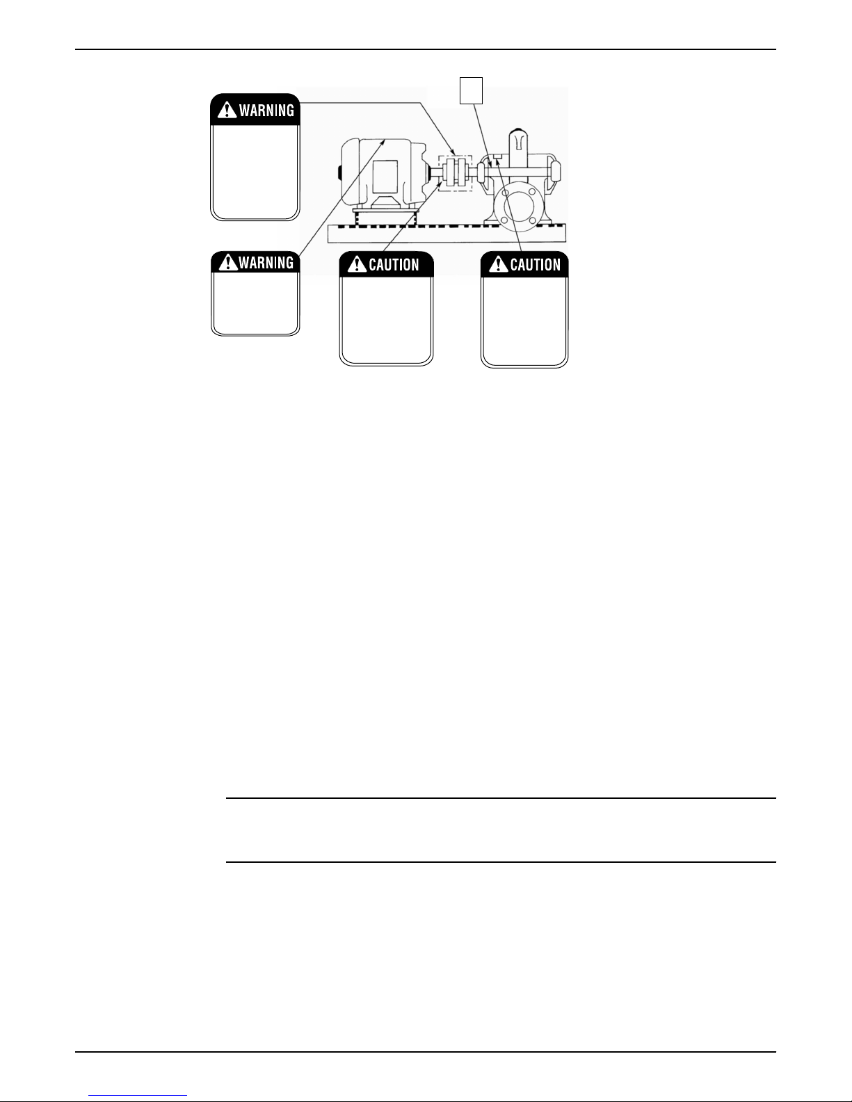
Make sure your pump has these safety instruction decals and that they are located as this
figure shows. If the decals are missing or illegible, contact your local sales and service
representative for a replacement.
4 G&L Pumps Series A-C 9100 Base Mounted Centrifugal Pumps INSTRUCTION MANUAL
Page 7
P70642
P70643
EYEBOLTS OR LIFTING
LUGS IF PROVIDED ARE
FOR LIFTING ONLY THE
COMPONENTS TO WHICH
THEY ARE ATTACHED.
FAILURE TO FOLLOW
INSTRUCTIONS COULD
RESULT IN INJURY OR
DEATH.
DO NOT RUN PUMP DRY.
SEAL DAMAGE MAY OCCUR.
INSPECT PUMP SEAL
REGULARLY FOR LEAKS.
REPLACE AS REQUIRED.
LUBRICATION REQUIRMENTS
CONSULT MANUALS.
PUMP: POLYUREA-BASED
GREASE
FAILURE TO FOLLOW
INSTRUCTIONS COULD
RESULT IN INJURY OR
PROPERTY DAMAGE.
ROTATING COMPONENTS
DISCONNECT AND LOCK
OUTPOWER BEFORE
SERVICING.
DO NOT OPERATE WITHOUT
ALL GUARDS IN PLACE.
CONSULT INSTALLATION
AND SERVICE INSTRUCTION
SHEET BEFORE OPERATING
OR SERVICING.
FAILURE TO FOLLOW
INSTRUCTIONS COULD
RESULT IN INJURY OR
DEATH.
P70820
COUPLER ALIGNMENT IS
REQUIRED! LEVEL AND
GROUT PUMP BEFORE USE!
CHECK ALIGNMENT BEFORE
GROUTING, AFTER SYSTEM
IS FILLED, AFTER SERVICING
PUMP, AND AS REQUIRED.
CONSULT THE SERVICE
INSTRUCTIONS FOR DETAILS.
FAILURE TO FOLLOW THESE
INSTRUCTIONS COULD
RESULT IN INJURY OR
PROPERTY DAMAGE.
RATING PLATE
P2002458
Make sure that all safety instruction decals are always clearly visible and readable.
1.3 User safety
1 Introduction and Safety
General safety rules
Safety equipment
Electrical connections
Precautions before work
These safety rules apply:
• Always keep the work area clean.
• Pay attention to the risks presented by gas and vapors in the work area.
• Avoid all electrical dangers. Pay attention to the risks of electric shock or arc flash
hazards.
• Always bear in mind the risk of drowning, electrical accidents, and burn injuries.
Use safety equipment according to the company regulations. Use this safety equipment
within the work area:
• Hard hat
• Safety goggles, preferably with side shields
• Protective shoes
• Protective gloves
• Gas mask
• Hearing protection
• First-aid kit
• Safety devices
NOTICE:
Never operate a unit unless safety devices are installed. Also see specific information
about safety devices in other chapters of this manual.
Electrical connections must be made by certified electricians in compliance with all
international, national, state, and local regulations. For more information about
requirements, see sections dealing specifically with electrical connections.
Observe these safety precautions before you work with the product or are in connection
G&L Pumps Series A-C 9100 Base Mounted Centrifugal Pumps INSTRUCTION MANUAL 5
with the product:
Page 8
1 Introduction and Safety
• Provide a suitable barrier around the work area, for example, a guard rail.
• Make sure that all safety guards are in place and secure.
• Make sure that you have a clear path of retreat.
• Make sure that the product cannot roll or fall over and injure people or damage
property.
• Make sure that the lifting equipment is in good condition.
• Use a lifting harness, a safety line, and a breathing device as required.
• Allow all system and pump components to cool before you handle them.
• Make sure that the product has been thoroughly cleaned.
• Disconnect and lock out power before you service the pump.
• Check the explosion risk before you weld or use electric hand tools.
1.3.1 Wash the skin and eyes
Follow these procedures for chemicals or hazardous fluids that have come into contact
with your eyes or your skin:
Condition Action
Chemicals or hazardous fluids in
eyes
Chemicals or hazardous fluids on
skin
1. Hold your eyelids apart forcibly with your fingers.
2. Rinse the eyes with eyewash or running water for at least 15 minutes.
3. Seek medical attention.
1. Remove contaminated clothing.
2. Wash the skin with soap and water for at least 1 minute.
3. Seek medical attention, if necessary.
1.4 Protecting the environment
Emissions and waste disposal
Observe the local regulations and codes regarding:
• Reporting of emissions to the appropriate authorities
• Sorting, recycling and disposal of solid or liquid waste
• Clean-up of spills
Exceptional sites
CAUTION: Radiation Hazard
Do NOT send the product to Xylem if it has been exposed to nuclear radiation, unless
Xylem has been informed and appropriate actions have been agreed upon.
Recycling guidelines
Always follow local laws and regulations regarding recycling.
6 G&L Pumps Series A-C 9100 Base Mounted Centrifugal Pumps INSTRUCTION MANUAL
Page 9
2 Transportation and Storage
2 Transportation and Storage
2.1 Examine the delivery
2.1.1 Examine the package
1. Examine the package for damaged or missing items upon delivery.
2. Record any damaged or missing items on the receipt and freight bill.
3. If anything is out of order, then file a claim with the shipping company.
If the product has been picked up at a distributor, make a claim directly to the
distributor.
2.1.2 Examine the unit
1. Remove packing materials from the product.
Dispose of all packing materials in accordance with local regulations.
2. To determine whether any parts have been damaged or are missing, examine the
product.
3. If applicable, unfasten the product by removing any screws, bolts, or straps.
Use care around nails and straps.
4. If there is any issue, then contact a sales representative.
Shipping information
• Pumps and drivers are normally shipped from the factory mounted and painted with
primer and one finish coat.
• Couplings are shipped either assembled or have the coupling hubs mounted on the
shafts and the connecting members removed.
• When the connecting members are removed, they will be packaged in a separate
container and shipped with the pump or attached to the base plate.
Shaft alignment
• Shafts are in alignment when the unit is shipped; however, misalignment can occur
due to shipping.
• Refer to recommended alignment procedures in this manual if it is necessary to realign
the shaft.
2.2 Safe handling requirements
WARNING:
• Personal protective equipment should be worn when handling this equipment.
• Transportation & installation of this equipment should only be performed by qualified
personnel.
• A professional rigging company should be consulted before lifting the pump
assembly.
• Only use properly sized, certified lifting equipment & lifting devices, including slings,
suitably rated for the weights to be lifted.
• Slings, when used, must be of identical materials to avoid differences in stretch rates.
• Do not use lifting devices that are frayed, kinked, unmarked, or worn.
• Lifting eyebolts fitted on single components of the assembly (pump or motor) must not
be used to lift the complete assembly.
• Failure to observe these instructions could result in equipment or property damage,
serious injury, or death.
The pump assembly can arrive in a variety of ways:
G&L Pumps Series A-C 9100 Base Mounted Centrifugal Pumps INSTRUCTION MANUAL 7
Page 10

2 Transportation and Storage
• Pump end only (bare pump)
• Pump less motor
• Pump, motor, & baseplate
Use the following recommended ways of handling HSC pump assemblies.
• The pump assembly should remain horizontal during transport and lifting.
• Lifting the pump end only (bare pump) should be done by placing one end of the
slings around or as close to the casing barrel as possible. After the slings are attached
to the unit, recheck to ensure they are securely in place. Make sure the slings are
adjusted to obtain an even lift.
Figure 1: Lifting pump end only with nylon sling, chain, or wire rope
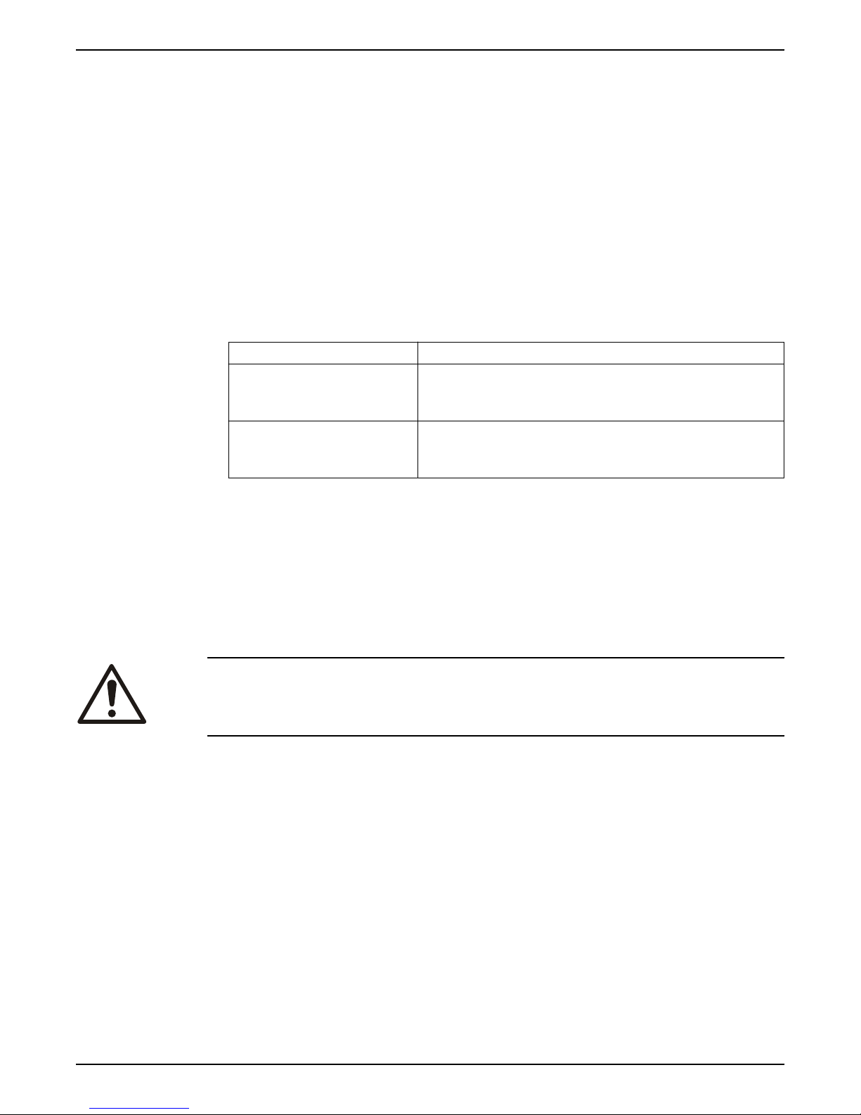
• Lifting the pump less motor or the pump, motor, & baseplate should be done by
utilizing a forklift under the entire unit. Always take extra precaution to ensure the
weight is balanced & equally distributed across both forks. When the baseplate of the
assembly is structural channel construction, the pump and base plate should be set in
place first. The motor should then be separately lifted & mounted to the unit.
• Pump, base, and driver assemblies where the base length exceeds 100 inches may not
be safe to lift as a complete assembly. Damage to the baseplate may occur. If the
driver has been mounted on the baseplate at the factory, it is safe to lift the entire
assembly. If driver has not been mounted at the factory and the overall baseplate
length exceeds 100 inches, do not lift the entire assembly consisting of pump, base,
and driver. Instead lift the pump and baseplate to its final location without the driver.
Then mount the driver.
8 G&L Pumps Series A-C 9100 Base Mounted Centrifugal Pumps INSTRUCTION MANUAL
Page 11
Figure 2: Lift using a forklift
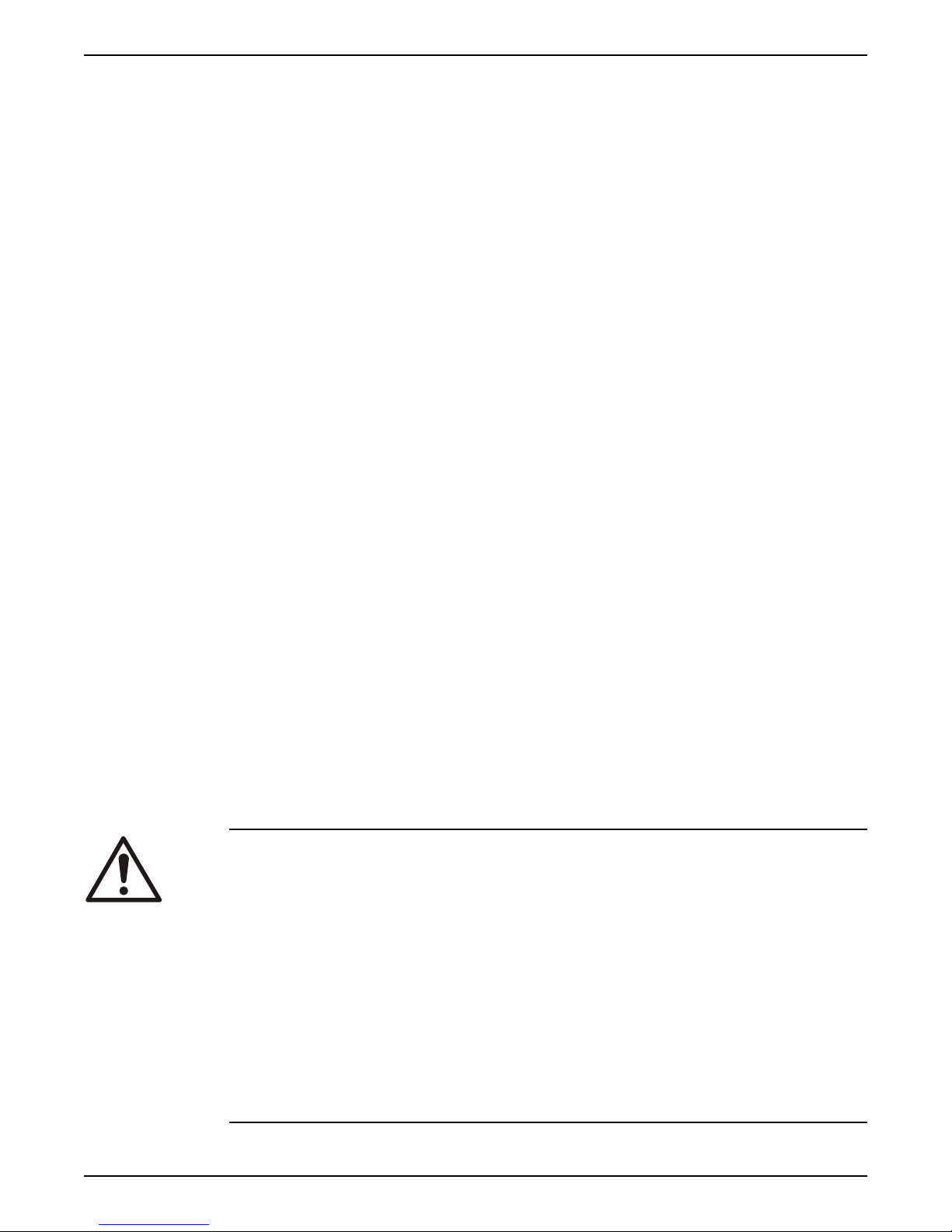
30° MAX.
2 Transportation and Storage
Figure 3: Vertical - Half Pedestal - Model 200
• Place nylon sling, chain or wire rope around both flanges. Use a latch hook or standard
shackle and end loops. Be sure the lifting equipment is of sufficient length to keep the
lift angle less than 30° from the vertical (See Figure 3).
Storage location
The product must be stored in a covered and dry location free from heat, dirt, and
vibrations.
G&L Pumps Series A-C 9100 Base Mounted Centrifugal Pumps INSTRUCTION MANUAL 9
Page 12

2 Transportation and Storage
NOTICE:
Protect the product against humidity, heat sources, and mechanical damage.
NOTICE:
Do not place heavy weights on the packed product.
2.3 Storage requirements
If the unit will not be installed and put into operation immediately upon arrival at the site,
or for an extended shutdown after the unit is in operation, the following requirements for
short-term storage apply:
• Store in a covered and dry location.
• Store the unit free from excessive cold or heat (below 32°F and above 110°F), dirt, and
vibration.
• Rotate the shaft by hand several times (10–15 turns) at least every 30 days.
For initial storage longer than three months, or for pump shut down after being in
operation longer than three months, contact your local sales and service representative
for long-term storage guidelines.
10 G&L Pumps Series A-C 9100 Base Mounted Centrifugal Pumps INSTRUCTION MANUAL
Page 13
3 Product Description
3.1 General description
Description
The pump is a centrifugal, frame-mounted pump. The following pump features make it
easy to install, operate, and service:
• High efficiency
• Rugged construction
• Compact design
• Foot-mounted volute
• Center drop out coupler
• regreasable bearings
• Horizontal split case
Intended applications
WARNING:
This product can expose you to chemicals including Lead, which is known to the State of
California to cause cancer and birth defects or other reproductive harm. For more
information go to: www.P65Warnings.ca.gov.
3 Product Description
The pump’s bronze fitted construction make it ideal for use with the following liquids:
• Unheated domestic and fresh water
• Boiler feed water
• Condensate
• Hydronic cooling or heating
• Pressure boosting
• General pumping
• Benign liquids
3.2 Operational specifications
Maximum working pressure
The maximum working pressure is listed on the pump nameplate.
Mechanical seal specifications
Seal type Parameter Value
Standard self-flushing pH range limits for Viton pH 7–9
Table notes
1. For use on closed or open systems which are relatively free of dirt and/or other
abrasive particles.
Liquid temperature range that
complies with the pH range limits for
Viton
-10˚F to 220˚F (-23˚C to 104˚C)
3.3 Nameplate information
The pump nameplate gives identification and rating information about the pump.
Permanent records for this pump are kept by the serial number and it must be used will all
correspondence and spare parts orders.
G&L Pumps Series A-C 9100 Base Mounted Centrifugal Pumps INSTRUCTION MANUAL 11
Page 14

21 3 4 5 6
7
8
9
G&L PUMPS
3 Product Description
Nameplate
1. Impeller diameter
2. Pump rotation — for example, LHR = left hand rotation
3. Pump size — for example, 8 x 8 x 17M
4. Serial number — for example, 1–21937–1–1
5. Driver HP
6. Identification number — for example, Month and year = CWP-11
7. Pump series and model number
8. Duty points — GPM, feet, RPM
9. Maximum working pressure
12 G&L Pumps Series A-C 9100 Base Mounted Centrifugal Pumps INSTRUCTION MANUAL
Page 15
4 Installation
4.1 Preinstallation
Precautions
WARNING:
• When installing in a potentially explosive environment, make sure that the motor is
properly certified.
• You must ground (earth) all electrical equipment. This applies to the pump equipment,
the driver, and any monitoring equipment. Test the ground (earth) lead to verify that it
is connected correctly.
• Motors without built-in protection must be provided with contactors and thermal
overload protection for single-phase motors, or starters with heaters for three-phase
motors. (See the nameplate on the drive unit to select properly-sized overloads.)
NOTICE:
Supervision by an authorized Xylem representative is recommended to ensure proper
installation. Failure to do so may result in equipment damage or decreased performance.
4 Installation
4.1.1 Pump location guidelines
WARNING:
Assembled units and their components are heavy. Failure to properly lift and support this
equipment can result in serious physical injury and/or equipment damage. Lift equipment
only at the specifically identified lifting points. Lifting devices such as eyebolts, slings, and
spreaders must be rated, selected, and used for the entire load being lifted.
Guideline Explanation/comment
Keep the pump as close to the liquid source as practically
possible.
If the pump is not on a closed system, locate the pump so that
the fewest number of bends or elbows in the suction pipe are
needed.
Make sure that the space around the pump is sufficient. This facilitates ventilation, inspection,
If you require lifting equipment such as a hoist or tackle, make
sure that there is enough space above the pump.
Protect the unit from weather and water damage due to rain,
flooding, and freezing temperatures.
Take into consideration the occurrence of unwanted noise and
vibration.
If the pump location is overhead, undertake special precautions
to reduce possible noise transmission.
Make sure there is a suitable power source available for the
pump driver.
This minimizes the friction loss and keeps the
suction piping as short as possible.
maintenance, and service.
This makes it easier to properly use the lifting
equipment and safely remove and relocate the
components to a safe location.
This is applicable if nothing else is specified.
The best pump location for noise and vibration
absorption is on a concrete floor with subsoil
underneath.
Consider a consultation with a noise specialist.
The electrical supply must match the motor
nameplate specifications.
G&L Pumps Series A-C 9100 Base Mounted Centrifugal Pumps INSTRUCTION MANUAL 13
Page 16
4
5
6
7
8
9
1
2
3
4 Installation
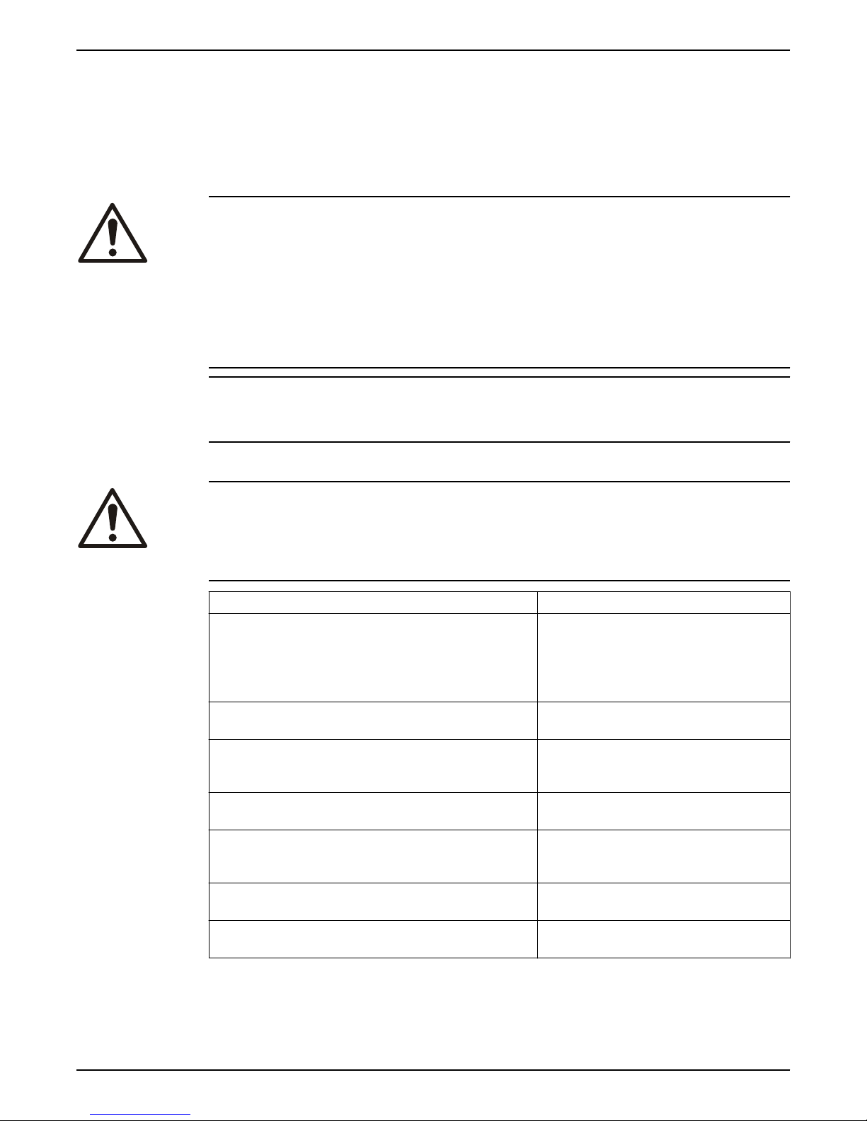
4.1.2 Typical installation
1. Compression tank (locate the compression tank on the suction side of the pump)
2. Air separator
3. Supply to system
4. Circuit setter
5. Triple duty valve
6. Isolation valve
7. From boiler chiller or converter
8. Cold water supply
9. Reducing valve
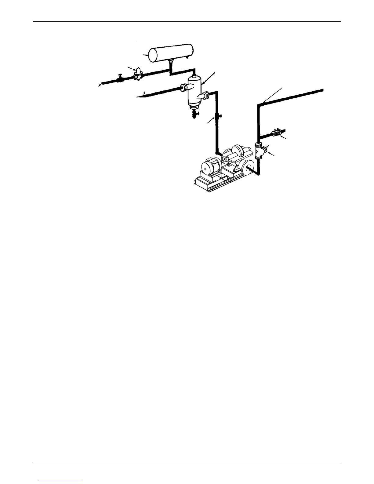
4.1.3 Foundation requirements
Requirements
• A substantial foundation and footing should be built to suit local conditions and form a
rigid support to maintain alignment.
• The foundation must be able to absorb any type of vibration and form a permanent,
rigid support for the unit.
• The foundation must weigh at least five times the weight of the pump unit.
• Pour the foundation without interruption to within 1/2 to 1–1/2 inches of the finished
height.
• The top surface of the foundation should be scored and grooved before the concrete
sets. This provides a bonding surface for the grout.
• Provide a flat, substantial concrete foundation in order to prevent strain and distortion
when you tighten the foundation bolts.
• Sleeve-type and J-type foundation bolts are most commonly used. Both designs allow
movement for the final bolt adjustment.
• Allow the foundation to cure for several days before you proceed with the pump
installation.
Diagram
• Allow enough bolt length for grout, shims, lower baseplate flange, nuts, and washers.
14 G&L Pumps Series A-C 9100 Base Mounted Centrifugal Pumps INSTRUCTION MANUAL
Page 17
2
3
1
4
1. Foundation bolt
4
1
5
2
3
6
7
8
2. Pipe sleeve
3. Washer
4. Built-up concrete foundation
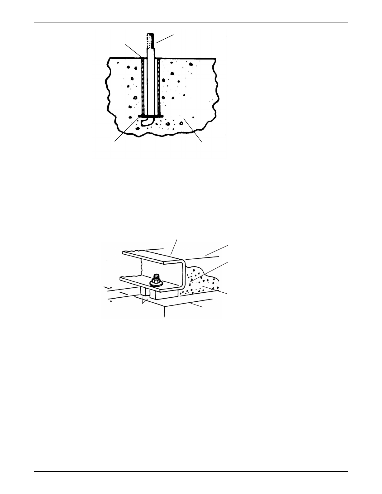
4.1.4 Level the base on a concrete foundation
1. Place the pump on its concrete foundation.
2. Place 1.00 in./(25.40 mm) thick steel shims or wedges on both sides of each anchor
bolt in order to support the pump .
This also provides a means of leveling the base.
4 Installation
1. Pump Base Rail
2. Grout only to top of base rail
3. Locate the shims to allow removal after grouting.
4. Grout
5. Concrete foundation
6. Shims
7. 1” (25.40 mm) Gap
8. Allow 1” for shims. Place on both sides of anchor bolts.
4.1.5 Grout the baseplate
Required equipment:
• Cleaners: Do not use an oil-based cleaner because the grout will not bond to it. See
the instructions provided by the grout manufacturer.
• Grout: Non-shrink grout is required.
1. Clean all the areas of the baseplate that will come into contact with the grout.
2. Build a dam around the foundation.
3. Thoroughly wet the foundation that will come into contact with the grout.
4. Pour grout through the grout hole into the baseplate up to the level of the dam.
When you pour the grout, remove air bubbles from it by using one of these methods:
G&L Pumps Series A-C 9100 Base Mounted Centrifugal Pumps INSTRUCTION MANUAL 15
Page 18
4 Installation
– Puddle with a vibrator.
– Pump the grout into place.
5. After the grout has thoroughly hardened, check the foundation bolts and tighten if
necessary. Check alignment after tightening the bolts.
6. After the grout has dried, apply an oil base paint to the exposed edges to prevent
moisture from coming in contact with the grout.
4.2 Coupling alignment
WARNING:
Always disconnect and lock out power to the driver before you perform any installation or
maintenance tasks. Failure to disconnect and lock out driver power will result in serious
physical injury.
Alignment guidelines
Follow these guidelines when you align the coupling:
• Only perform alignment by moving or shimming the motor.
• Since adjustments in one direction can alter the alignment in another direction, check
the alignment in all directions after you make a correction.
• Make sure that the pump and motor bolts are tight when you take all measurements.
• Perform a final alignment check after the unit reaches its final operating temperature.
4.2.1 Prepare for alignment
1. Check the pump and motor shafts and remove any paint, burrs, and rust.
2. Slide the hubs and bushings on the shafts with keys.
3. Hold one half element on the hubs in order to determine the appropriate hub spacing.
4. If you use spacer elements with high speed rings, hold both half elements on the hubs
in order to make sure the hubs do not interfere with the rings.
5. You can install the hubs with the hub extension facing in or out.
Make sure the shaft extends into the hubs at least 0.8 times the diameter of the shaft.
6. Lightly fasten the hubs to the shafts in order to prevent them from moving during
alignment.
7. Align the hubs to the values shown in Maximum allowable misalignment for couplings.
You can perform alignment with lasers, dial indicators, or with a straight edge and
calipers.
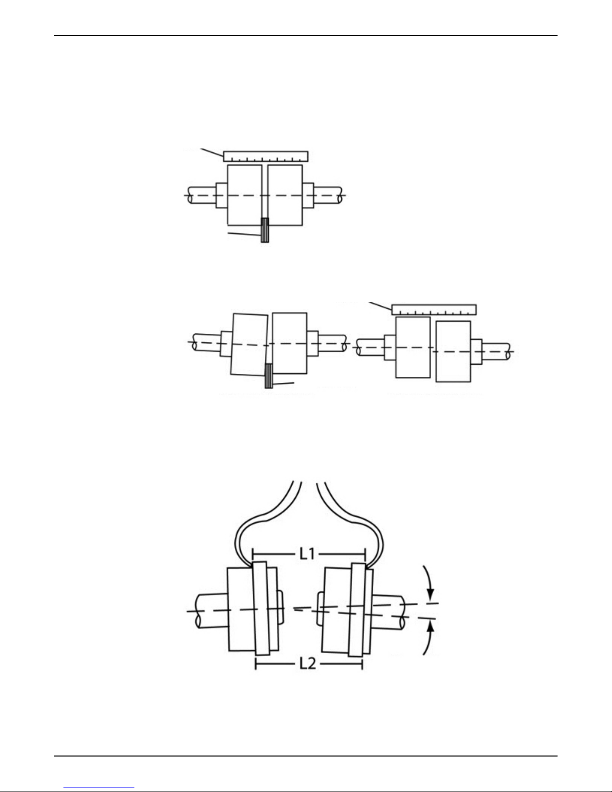
4.2.2 Align the pump using a straight edge and calipers
1. Check the angular misalignment:
Tool Procedure
Calipers 1. Gauge the distance between the two hubs at various points around the circumference.
Do not rotate the shafts.
2. Reposition the equipment until the difference between the minimum and maximum
distance values is within the permissible range.
See Maximum allowable misalignment for couplings.
Feeler
gauges
2. Check the parallel alignment:
a) Place a straight edge across the two hubs.
b) Measure the maximum offset at various points around the periphery of the hubs.
1. Insert feeler gauges between the coupling faces at various points around the circumference.
Do not rotate the shafts.
2. Reposition the equipment until the difference between the minimum and maximum
distance values is within the permissible range.
16 G&L Pumps Series A-C 9100 Base Mounted Centrifugal Pumps INSTRUCTION MANUAL
Page 19
Do not rotate the shafts.
1
2
1
2
Angular Parallel
c) Reposition the equipment until the offset is within the permissible range.
See Maximum allowable misalignment for couplings.
A coupling with a 3° angular misalignment will have a 0.191 in. (0.485 cm)
difference in measurements between L1 and L2. This is within the 0° to 4°
misalignment that is allowed for that size of coupling.
1. Straight edge
2. Feeler guage
Figure 4: Check the alignment using a straight edge - correct
4 Installation
1. Straight edge
2. Feeler gauge
Figure 5: Check the alignment using a straight edge - incorrect
In the following Figure, the arrows show the angular misalignment:
Figure 6: Check the alignment using calipers
G&L Pumps Series A-C 9100 Base Mounted Centrifugal Pumps INSTRUCTION MANUAL 17
Page 20
P
A
R
1
1
2
3
4 Installation
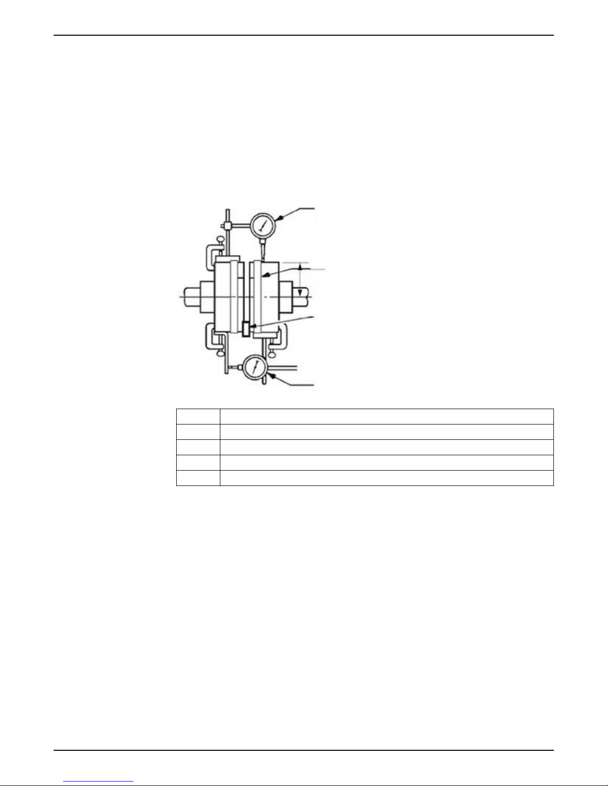
4.2.3 Align the pump using a dial indicator
• Make sure that each hub is secured to its respective shaft and that all connecting
and/or spacing elements are removed at this time.
• The gap between the coupling hubs is set by the manufacturer before the units are
shipped. However, this dimension should be checked. Refer to the coupling
manufacturer’s specifications supplied with the unit.
1. Check the angular misalignment:
a) Mount the dial indicator base to one coupling half, or shaft.
b) Position the dial indicator button on the front face or rear face of the opposite
coupling half.
c) Mark the index lines on the coupling halves as the following Figure shows:
A Angular alignment
P Parallel alignment
1 Dial indicators
2 Index line
3 Resilient separator
Figure 7: Pump alignment via dial indicator
d) Set the dial to zero.
e) Rotate both coupling halves together and make sure that the index lines remain
matched.
f) Reposition the equipment until the offset is within the permissible value.
2. Check the parallel misalignment:
a) Mount the dial indicator base to one coupling half, or shaft.
b) Position the dial indicator button on the outside diameter of the opposite coupling
half.
c) Set the dial to zero.
d) Rotate both coupling halves together and make sure that the index lines remain
matched.
e) Reposition the equipment until the offset is within the permissible value.
f) Assemble coupling. Tighten all bolts and set screw(s). It may be necessary to repeat
steps for a final check.
For single element couplings, a satisfactory parallel misalignment is .004” T.I.R., while a
satisfactory angular misalignment is .004” T.I.R. per inch of radius R.
18 G&L Pumps Series A-C 9100 Base Mounted Centrifugal Pumps INSTRUCTION MANUAL
Page 21

4.2.4 Final alignment
You cannot perform the final alignment until you initially operate the pump long enough
to reach operating temperature. When the pump reaches the normal operating
temperature, then secure the pump and re-check the alignment. Make sure that you
compensate for temperature accordingly.
NOTICE:
Elastomeric couplings are specifically designed to accommodate angular shaft
misalignment, as well as parallel offset of the pump and motor shafts. However, the
amount of the offset and/or misalignment depends on the style of the applied flexible
coupling. If you do not correct this coupling misalignment, there is a significant impact on
the overall life of the mechanical seals and the bearings of the pump.
4.2.5 Optional alignment procedure
If desired, the pump and motor feet can be doweled to the base after final alignment is
complete. This should not be done until the unit has been run for a sufficient length of
time and alignment is with the tolerance. See doweling section.
NOTE: Pump may have been doweled to base at factory.
4.2.6 Dowel the pump and driving unit
1. Drill holes through diagonally opposite feet and into the base. Holes must be of a
diameter 1/64 inch less then the diameter of the dowel pins.
2. Ream the holes in feet and base to the proper diameter for the pins (light push fit).
Clean out the chips.
3. Insert pins to be approximately flush with feet.
4 Installation
4.2.7 Coupler limitations
Brand name Suitable for
variable speed
application
Falk Lifelign
Gear
G20 (NonSpacer)
G32 (Spacer)
Yes
Coupler size Minimum
1010G 1030 RPM
1015G 700 RPM 0.00300
1020G 550 RPM 0.00300
1025G 460 RPM 0.00400
1030G 380 RPM 0.00500
1035G 330 RPM 0.00600
4.3 Piping checklists
4.3.1 Piping checklist
WARNING:
• The heating of water and other fluids causes volumetric expansion. The associated
forces can cause the failure of system components and the release of hightemperature fluids. In order to prevent this, install properly sized and located
compression tanks and pressure-relief valves. Failure to follow these instructions can
result in serious personal injury or death, or property damage.
• Avoid serious personal injury and property damage. Make sure that the flange bolts
are adequately torqued.
• Never force piping to make a connection with a pump.
recommended
speed
Angular
misalignment
installation
limits (inch)
All sizes: 1/8°
per gear mesh
Parallel
misalignment
installation
limits (inch)
0.00200
Maximum
temperature
250°F –20°F
Minimum
temperature
G&L Pumps Series A-C 9100 Base Mounted Centrifugal Pumps INSTRUCTION MANUAL 19
Page 22

4 Installation
Check Explanation/Comment
Always run piping to the pump. Do not move pump to pipe. This could make final
alignment impossible.
Check that the suction and discharge piping are
supported independently near the pump and properly
This helps to avoid strain on the pump when the flange
bolts are tightened.
aligned.
Check that pipe hangers or other supports are installed. Place supports at necessary intervals.
Check if expansion joints are installed correctly. When expansion joints are used in the piping system,
they must be installed beyond the piping supports
closest to the pump. Tie bolts should be used with
expansion joints to prevent pipe strain. Do not install
expansion joints next to the pump or in any way that
would cause a strain on the pump resulting in system
pressure changes.
Check that pipe size is larger at pump connections. It is usually advisable to increase the size of both suction
and discharge pipes at the pump connection to decrease
the loss of head from friction.
Install piping as straight as possible to avoid unnecessary
bends.
Use 45 degree or long sweep 90 degree fitting to
decrease friction losses.
Make sure that all piping joints are air tight.
Where flanged joints are used, assure that inside
diameters match properly.
Do not “spring” piping when making any connections.
Provide for pipe expansion when hot fluids are to be
pumped.
4.3.2 Suction piping checklist
The sizing and installation of the suction piping is extremely important. It must be selected
and installed so that pressure losses are minimized and sufficient liquid flows into the
pump when it is started and operated. Many NPSH problems can be directly attributed to
improper suction piping systems.
Piping checklist
Check Explanation/comment Checked
Keep the suction piping short in length, as
direct as possible, and never smaller in
diameter than the pump suction opening.
Check that the elbows in the suction piping
for horizontal double-suction pumps are
installed per the Hydraulics Institute
Standards since there is always an uneven
turbulent flow around an elbow.
Check that pipe reducers on the inlet side
have no more than one pipe diameter
reduction in a single reducer.
When operating on a suction lift, check that
the suction pipe slopes upward to the
pump nozzle.
If the suction pipe is short, the pipe diameter can be
the same size as the suction opening. If longer suction
piping is required, pipes should be one or two sizes
larger than the opening depending on piping length.
When there is an elbow in a position other than the
vertical when in relation to the pump suction nozzle,
this causes more liquid to enter one side of the
impeller than the other. The result is highly
unequalized thrust loads that overheat the bearings
and cause rapid wear, which adversely affects the
hydraulic performance. See the Example of
unbalanced loading figure.
This avoids excessive turbulence and noise.
A horizontal suction line must have a gradual rise to
the pump. Any high point in the pipe can become
filled with air and prevent proper operation of the
pump.
20 G&L Pumps Series A-C 9100 Base Mounted Centrifugal Pumps INSTRUCTION MANUAL
Page 23
Check Explanation/comment Checked
1
2
3
4
5
2
3
4
1
1
(Optional) You can install a short section of
pipe adjacent to the suction flange such as
Dutchman or a spool piece that is designed
so that it can be readily dropped out of the
line.
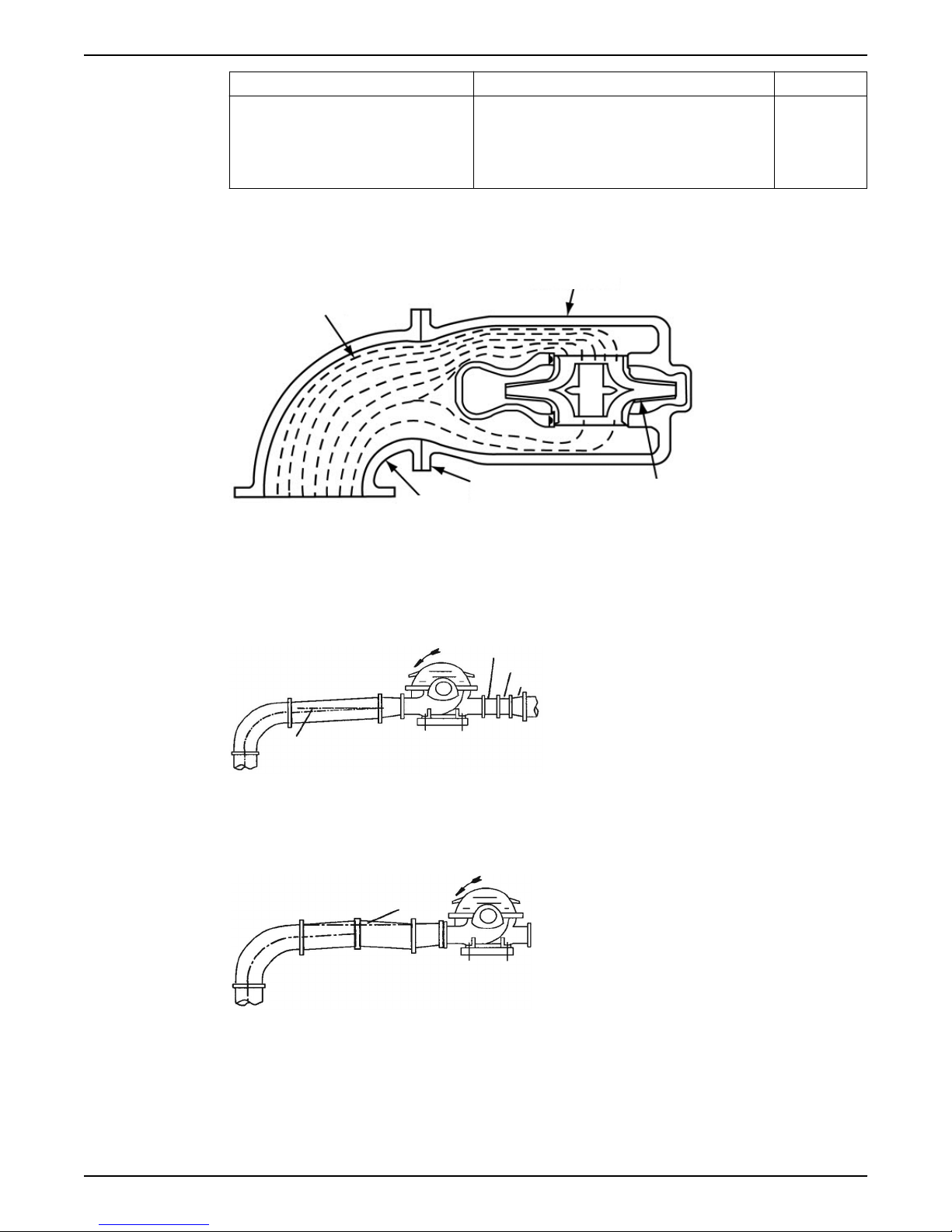
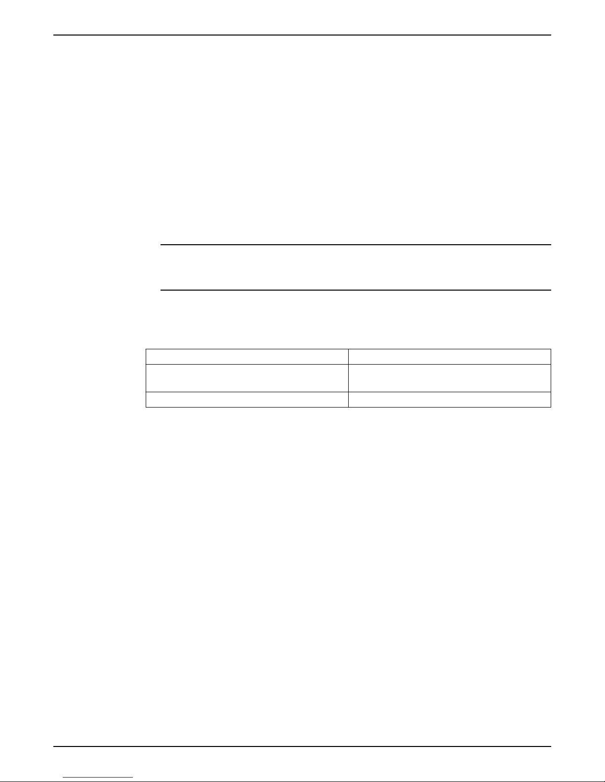
Example of unbalanced loading
This figure shows the unbalanced loading of a double-suction impeller due to the uneven
flow around an elbow that is adjacent to the pump:
4 Installation
This facilitates the cleansing of the liquid passage of
the pump without dismantling the pump. With this
arrangement, anything that clogs the impeller is
accessible with the removal of the spool piece or pipe
section.
Examples
1. Pump casing
2. Impeller
3. Pump suction flange
4. Suction elbow
5. Water velocity increases here and causes a greater flow to one side of the impeller.
Figure 8: Unbalanced loading of double-suction impeller
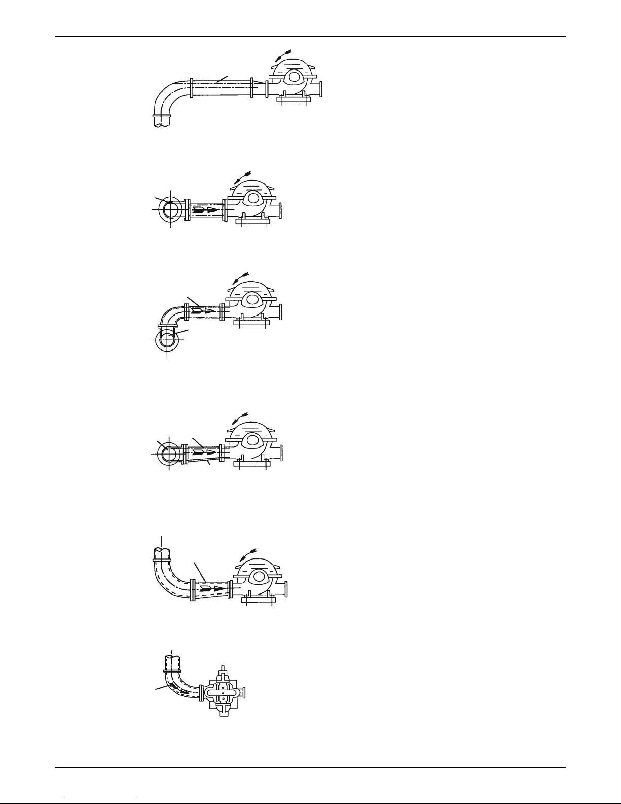
1. Level centerline of pipe
2. Check valve
3. Gate valve
4. Increaser
Figure 9: Suction pipe installed with a gradual rise to the pump – correct
1. Air pocket
Figure 10: Suction pipe installed with a gradual rise to the pump – incorrect
G&L Pumps Series A-C 9100 Base Mounted Centrifugal Pumps INSTRUCTION MANUAL 21
Page 24
1
1
2
1
3
2
1
1
1
4 Installation
1. Air pocket
Figure 11: Suction pipe installed with a reducer – incorrect
1. Air pocket
Figure 12: Incorrect
1. No air pockets
2. Gradual rise
Figure 13: Correct
1. No air pockets
2. Eccentric reducer
3. Gradual rise
Figure 14: Gradual rise to the pump – correct
1. Distance plus eccentric reducer straightens the flow
Figure 15: Suction pipe above the pump – correct
22 G&L Pumps Series A-C 9100 Base Mounted Centrifugal Pumps INSTRUCTION MANUAL
1. Path of the water
Figure 16: Suction pipe above the pump – incorrect
Page 25
5 Commissioning, Startup, Operation, and Shutdown
5 Commissioning, Startup,
Operation, and Shutdown
5.1 Preparation for startup
WARNING:
• Failure to follow these precautions before you start the unit will lead to serious
personal injury and equipment failure.
• Do not operate the pump below the minimum rated flows or with the suction or
discharge valves closed. These conditions can create an explosive hazard due to
vaporization of pumped fluid and can quickly lead to pump failure and physical injury.
• Always disconnect and lock out power to the driver before you perform any installation
or maintenance tasks. Failure to disconnect and lock out driver power will result in
serious physical injury.
• Operating the pump in reverse rotation can result in the contact of metal parts, heat
generation, and breach of containment.
• Make sure that all components are properly guarded or insulated when operating at
extremely high or low temperatures.
NOTICE:
• Verify the driver settings before you start any pump.
• Make sure that the warm-up rate does not exceed 2.5°F (1.4°C) per minute.
You must follow these precautions before you start the pump:
• Flush and clear the system thoroughly to remove dirt or debris in the pipe system in
order to prevent premature failure at initial startup.
• If temperatures of the pumped fluid will exceed 200°F (93°C), then warm up the pump
prior to operation. Circulate a small amount of fluid through the pump until the casing
temperature is within 100°F (38°C) of the fluid temperature.
At initial startup, do not adjust the variable-speed drivers or check for speed governor or
over-speed trip settings while the variable-speed driver is coupled to the pump. If the
settings have not been verified, then uncouple the unit and refer to instructions supplied
by the driver manufacturer.
5.1.1 Pre-start checks
Before initial start of the pump, make the following inspections:
1. Check alignment between pump and motor.
2. Check all connections to motor and starting device with wiring diagram. Check
voltage, phase, and frequency on motor nameplate with line circuit.
3. Check suction and discharge piping and pressure gauges for proper operation.
4. Check impeller adjustment, see specific section for proper adjustment.
5. Turn rotating element by hand to assure that it rotates freely.
6. Check driver lubrication.
7. Assure that pump bearings are properly lubricated.
8. Assure that coupling is properly lubricated, if required.
G&L Pumps Series A-C 9100 Base Mounted Centrifugal Pumps INSTRUCTION MANUAL 23
Page 26

5 Commissioning, Startup, Operation, and Shutdown
9. Assure that pump is full of liquid (see priming) and all valves are properly set and
operational, with the discharge valve closed, and the suction valve open.
10.Check rotation. Be sure that the driver operates in the direction indicated by the arrow
on the pump casing as serious damage can result if the pump is operated with
incorrect rotation. Check rotation each time the motor leads have been disconnected.
5.1.2 Priming
Type of installation Procedure
Positive head on the suction Open the suction and vent valve and allow the liquid to enter the
casing.
Suction lift Use other methods such as foot valves, ejectors or by manually filling
the casing and suction line.
5.1.3 Starting
1. Close drain valves and valve in discharge line.
2. Open fully all valves in the suction line.
3. Prime the pump.
NOTE: If the pump does not prime properly, or loses prime during start-up, it should
be shut down and the condition corrected before the procedure is repeated.
4. When the pump is operating at full speed, open the discharge valve slowly. This
should be done after start-up to prevent damage to pump by operating at zero flow.
5.1.4 Operating checks
1. Check the pump and piping to assure that there are no leaks.
2. Check and record pressure gauge readings for future reference.
3. Check and record voltage, amperage per phase, and kw if an indicating wattmeter is
available.
4. Check bearings for lubrication and temperature. Normal temperature is 180°F
maximum.
5. Make all pump output adjustments with the discharge line.
CAUTION:
• Do not throttle the suction line to adjust the pump output.
• Do not let heated pump temperature rise above 150°F.
5.1.5 Check the rotation
WARNING:
• Operating the pump in reverse rotation can result in the contact of metal parts, heat
generation, and breach of containment.
• Always disconnect and lock out power to the driver before you perform any installation
or maintenance tasks. Failure to disconnect and lock out driver power will result in
serious physical injury.
1. Unlock power to the driver.
2. Make sure that everyone is clear, and then jog the driver long enough to determine
that the direction of rotation corresponds to the arrow on the pump.
3. Lock out power to the driver.
24 G&L Pumps Series A-C 9100 Base Mounted Centrifugal Pumps INSTRUCTION MANUAL
Page 27

5.1.6 Freezing protection
1 1
2 2
3
4 5
NOTICE:
Do not expose an idle pump to freezing conditions. Drain all liquid that is inside the pump
and connected pipes. Failure to do so can cause liquid to freeze and damage the pump.
Pumps that are shut down during freezing conditions should be protected by one of the
following methods:
• Drain the pump; remove all liquids from the casing.
• Keep fluid moving in the pump and insulate or heat the pump to prevent freezing.
5.1.7 Change the rotation
The pump can be operated left hand or right hand when viewed from the pump end of
the pump. If you wish to reverse the suction and discharge nozzles, this can be
accomplished with the same pump as follows. IMPORTANT: Refer to the disassembly and
assembly procedures in this manual for proper disassembly and assembly techniques.
1. Remove the impeller from the shaft, turn it 180° and replace it on the shaft. Note:
Impeller can only come off from the outboard end.
2. With the rotating element out of the casing, remove the casing from the bedplate and
turn 180°.
3. Set the rotating element back in the casing and reassemble the pump.
– The impeller and casing are in the same relationship to each other as they were
originally. The shaft and motor are also in the same relationship to each other as
they were originally.
4. Reassemble pump and realign the coupling as called for in the alignment procedures.
5 Commissioning, Startup, Operation, and Shutdown
WARNING:
Never operate a pump without a properly installed coupling guard.
Personal injury will occur if you run the pump without a coupling guard.
5. The rotation of the motor must be changed by switching the motor leads.
– Unless the motor rotation is reversed, the impeller will run backward.
Figure 17: Correct relationship of impeller and casing
1. Rotation
2. Discharge
3. Suction
4. Left-hand rotation viewed from the pump end
5. Right-hand rotation viewed from the pump end
G&L Pumps Series A-C 9100 Base Mounted Centrifugal Pumps INSTRUCTION MANUAL 25
Page 28

5 Commissioning, Startup, Operation, and Shutdown
Figure 18: Main joint bolts
26 G&L Pumps Series A-C 9100 Base Mounted Centrifugal Pumps INSTRUCTION MANUAL
Page 29

6 Maintenance
6.1 Maintenance schedule
CAUTION:
Shorten the inspection intervals if the pumped liquid is abrasive or corrosive, or if the
environment is classified as potentially explosive.
NOTICE:
This timetable assumes that the unit has been constantly monitored after startup. Adjust
the timetable for any extreme or unusual applications or conditions.
Monthly inspections
Check the bearing temperature with a thermometer. Do not check the temperature by
hand. If the bearings are running over 180°F (82°C), then there is too much or too little
lubricant.
If changing the lubricant or adjusting to the proper level does not correct the condition,
then disassemble and inspect the bearings.
6 Maintenance
Three-month inspections
Perform these tasks every three months:
• Check the oil on oil-lubricated units.
• Check the grease-lubricated bearings for saponification. This condition is usually
Six-month inspections
Perform these tasks every six months:
• Check the packing and replace if necessary. Use the grade recommended. Make sure
• Take vibration readings on the bearing housings. Compare the readings with the last
• Check the shaft or shaft sleeve for scoring. Scoring accelerates packing wear.
• Check the alignment of the pump and driver. Shim the units if necessary. If
Annual inspections
Perform these inspections one time each year:
• Remove the upper half of the casing. Inspect the pump thoroughly for wear. Order
• Check the wear ring clearances. Replace the wear rings when clearances become
• Remove any deposit or scaling.
• Clean out the stuffing box piping.
• Measure the total dynamic suction and discharge head in order to test pump
caused by the infiltration of water or other fluid. Saponification gives the grease a
whitish color. If this condition occurs, then wash out the bearings with a clean industrial
solvent and replace the grease with the proper type as recommended.
the seal cages are centered in the stuffing box at the entrance of the stuffing box
piping connection.
set of readings to check for possible pump component failure.
misalignment reoccurs frequently, then inspect the entire piping system. Unbolt the
piping at the suction and discharge flanges to see if it springs away, which indicates
strain on the casing. Inspect all piping supports for soundness and effective support of
load. Correct as necessary.
replacement parts if necessary.
three times their normal clearance or when you observe a significant decrease in
discharge pressure for the same flow rate.
performance and pipe condition. Record the figures and compare them with the
G&L Pumps Series A-C 9100 Base Mounted Centrifugal Pumps INSTRUCTION MANUAL 27
Page 30

6 Maintenance
figures of the last test. This is especially important where the pumped liquid tends to
form a deposit on internal surfaces.
• Inspect foot valves and check valves. A faulty foot or check valve will cause poor
performance. The check valve safeguards against water hammer when the pump
stops.
6.2 Flood-damaged pumps
If the pump is properly sealed at all joints and connected to both suction and discharge,
then it will exclude outside liquid. Therefore, it is only necessary to service the bearings,
stuffing box, and coupling after flood damage.
Perform the following service on a centrifugal pump after a flooded condition:
• Dismantle the frame, and then inspect the bearings for any rusted or badly worn
surfaces. Clean as necessary. If the bearings are free from rust and wear, then
reassemble and relubricate them with one of the recommended lubricants.
Depending on the length of time the pump has remained in the flooded area, it is
unlikely that bearing replacement is necessary. Only replace the bearings if rust or
worn surfaces appear.
• Inspect the stuffing box and clean out any foreign matter that will clog the box.
Replace packing that appears to be worn or no longer regulates leakage properly.
Clean and thoroughly flush mechanical seals.
• Dismantle and thoroughly clean the couplings. Lubricate the couplings where required
with one of the lubricants recommended by the coupling manufacturer.
6.3 Bearing maintenance
Bearing lubrication — Oil
Oil lubrication pumps are installed with Trico oilers. The oilers keep the oil level in the
housing constant.
Figure 19: Trico oiler
After the pump has been installed:
1. Flush the housing to remove dirt, grit, and other impurities that may have entered the
bearing housing during shipment or installation.
2. Refill the housing with proper lubricant. The housing must be filled using the Trico
oiler.
– The oil level will be maintained by the Trico oiler. See the Service section for proper
instructions.
28 G&L Pumps Series A-C 9100 Base Mounted Centrifugal Pumps INSTRUCTION MANUAL
Page 31

6 Maintenance
A Mobile Oil, DTE Medium, or equal, meeting the following specification will provide
satisfactory lubrication. Similar oils can be furnished by all major oil companies. It is the
responsibility of the oil vendor to supply a suitable lubricant.
Saybolt viscosity at 100°F 215 SSU-240 SSU
Saybolt viscosity at 210°F 49SSU
Viscosity index, minimum 95
API gravity 28–33
Pour point, maximum +20°F
Flash point, minimum 400°F
Additives Rust and oxidation inhibitors
ISO viscosity 46
NOTES:
• Oils from different suppliers should not be mixed.
• Engine oils are not recommended.
• The oil should be non-foaming, well refined, good grade, straight cut, filtered mineral
oil. It must be free from water, sediment, resin, soaps, acid, and fillers of any kind.
In installations with moderate temperature changes, low humidity, and a clean
atmosphere, the oil should be changed after approximately 1000 hours of operation. The
oil should be inspected at this time to determine the operating period before the next oil
change. Oil change periods may be increased up to 200–4000 hours based on an 8000
hour year. Check the oil frequently for moisture, dirt, or signs of “breakdown,” especially
during the first 1000 hours.
CAUTION:
Do not over oil; This causes the bearings to run hot.
Bearing lubrication schedule
Type of bearing First lubrication,
assembled pumps
First lubrication,
replacement bearings
and replacement
bearing frames
Greaselubricated
bearings
Not applicable,
lubricated before
shipment
Hand pack bearings
before pressing on the
shaft. After bearing
frame assembly, follow
relube instructions to
lube bearings.
6.3.1 Regrease the grease-lubricated bearings
It is important to lubricate pumps and motors that require regreasing with the proper
grease. See the motor service instructions and nameplate for motor regreasing
information. Pumps are to be regreased using the grease types listed below or approved
equal. Always keep pump and motor properly lubricated.
Lubrication interval, pump, polyurea-based grease,
operating hours
• 3600 hours, 2 pole
• 7200 hours, 4 pole
• 50% for severe conditions: dirty, wet and/or
above 100°F (38°C) ambient
• 50% for bearing frame temperature above 180°F
(82°C)
• 75% for lithium-based grease
NOTICE:
Make sure that the grease container, the greasing device, and the fittings are clean.
Failure to do this can result in impurities entering the bearing housing when you regrease
the bearings.
G&L Pumps Series A-C 9100 Base Mounted Centrifugal Pumps INSTRUCTION MANUAL 29
Page 32
6 Maintenance
1. With fully enclosed coupling guards, regrease pump while pump is running.
a) With old style open ended guards, stop pump, re-grease, and hand turn shaft
before re-starting.
2. Wipe dirt from the grease fittings before greasing.
3. Fill both of the grease cavities through the fittings with the recommended grease. Stop
when grease leaks out at shaft.
4. If needed, stop pump and wipe off excess grease.
5. Restart pump.
The bearing temperature usually rises after you regrease due to an excess supply of
grease. Temperatures return to normal in about two to four operating hours as the pump
runs and purges the excess grease from the bearings. Maximum normal bearing housing
temperature for polyurea-based grease is 225°F (107°C) and for lithium-based grease
180°F (82°C).
6.3.2 Lubricating grease requirements
NOTICE:
• Never mix greases of different consistencies (NLGI 1 or 3 with NLGI 2) or with different
thickeners. For example, never mix a lithium-based grease with a polyurea-based
grease. This can result in decreased performance.
• Remove the bearings and old grease if you need to change the grease type or
consistency. Failure to do so can result in equipment damage or decreased
performance.
Specifications — grease types
Polyurea-based greases Lithium-based greases, NLGI 2
Pumps built on or after Dec 1, 2014 use Polyurea-based
greases. See date code label and lubrication label on
pump or bearing frame indicating polyurea-base grease
ExxonMobil PolyrexTM EM Shell Gadus® S2 V100 2 (was Alvania RL 2)
Chevron SRI NLGI 2 Chevron Multifak® EP 2
Shell Gadus® S5 T100 2 ExxonMobil UnirexTM N2
6.4 Shaft-seal maintenance
6.4.1 Mechanical seal maintenance
Keep in mind the following general rules regarding mechanical seal maintenance. Refer
to the instructions provided by the seal manufacturer for detailed information.
• Mechanical seals are precision products that must be treated with care. Use special
care when handling seals. Make sure that oil and parts are clean in order to prevent
scratching the finely lapped sealing faces. Even light scratches on these faces can
result in leaky seals.
• Mechanical seals typically require no adjustment or maintenance except for routine
replacement of worn or broken parts.
• A used mechanical seal should not be put back into service unless the sealing faces
have been replaced or relapped. Relapping is practical only for seals that are 2 in. (5.1
cm) or larger.
For optimum seal life, always follow these precautions:
• Keep the seal faces as clean as possible.
• Keep the seal as cool as possible.
• Make sure the seal always has proper lubrication.
• If the seal is lubricated with filtered fluid, then clean the filter frequently.
Pumps built before Dec 1, 2014 were built with Lithiumbased greases, NLGI 2, and do not have lubrication label
on pump or bearing frame indicating pump grease type
30 G&L Pumps Series A-C 9100 Base Mounted Centrifugal Pumps INSTRUCTION MANUAL
Page 33
6.4.2 Packed stuffing box maintenance
Check or instruction Explanation/comment
When starting a pump with fiber packing for
the first time, make sure that the packing is
slightly loose without causing an air leak. As
the pump runs in, gradually tighten the
gland bolts evenly.
Turn the rotating element by hand. The stuffing box is improperly packed or adjusted if friction in the box
After the pump has been in operation for
some time and the packing is completely run
in, check that the stuffing box leaks at the rate
of 40–60 drops per minute.
6 Maintenance
Never draw the gland to the point where the packing is compressed
too tightly and no leakage occurs. This will burn the packing, score
the shaft sleeve, and prevent circulation of the liquid that cools the
packing.
prevents turning the rotating element by hand. A properly operated
stuffing box runs lukewarm with a slow drip of sealing liquid.
This indicates proper packing, shaft sleeve lubrication, and cooling.
NOTICE:
Eccentricity of the shaft or sleeve through the packing can result in
excess leakage. Make sure that the parts are properly centered.
Check the packing frequently and replace as
service indicates.
Check the condition of the shaft or sleeve for
possible scoring or eccentricity and make
replacements as necessary.
When placing new, non-asbestos packing
into the stuffing box, open the molded rings
sideways and push the joints into the stuffing
box first. Then install the rings one at a time,
making sure to seat each ring firmly. Stagger
the joints at a 90° rotation from each
preceding joint.
Six months is a reasonable expected life, depending on operating
conditions. Use a packing tool in order to remove all old packing
from the stuffing box. Never reuse old packing or add new rings to
old packing. Clean the stuffing box thoroughly before you install new
packing.
—
—
6.5 Cleaning without dismantling the pump
A short section of pipe so designed that it can be readily dropped out of the line can be
installed adjacent to the suction flange. With this arrangement, any matter clogging the
impeller is accessible by removing the pipe section.
If the pump cannot be freed of clogging after the above methods have been tried,
dismantle the unit as previously described to locate the trouble.
6.6 Disassembly
6.6.1 Disassembly precautions
This manual clearly identifies accepted methods for disassembling units. These methods
must be adhered to.
WARNING:
• Make sure that the pump is isolated from the system and that pressure is relieved
before you disassemble the pump, remove plugs, open vent or drain valves, or
disconnect the piping.
• Always disconnect and lock out power to the driver before you perform any installation
or maintenance tasks. Failure to disconnect and lock out driver power will result in
serious physical injury.
• Crush hazard. The unit and the components can be heavy. Use proper lifting methods
and wear steel-toed shoes at all times.
G&L Pumps Series A-C 9100 Base Mounted Centrifugal Pumps INSTRUCTION MANUAL 31
Page 34
1
2
3
4
5
6
12
10
9
8
7
11
6 Maintenance
NOTICE:
Make sure that all replacement parts are available before you disassemble the pump for
overhaul.
6.6.2 Drain the pump
CAUTION:
• Allow all system and pump components to cool before you handle them to prevent
physical injury.
1. Close the isolation valves on the suction and discharge sides of the pump.
You must drain the system if no valves are installed.
2. Open the drain valve.
Do not proceed until liquid stops coming out of the drain valve. If liquid continues to
flow from the drain valve, the isolation valves are not sealing properly and you must
repair them before you proceed.
3. Leave the drain valve open and remove the drain plug located on the bottom of the
pump housing.
Do not reinstall the plug or close the drain valve until the reassembly is complete.
4. Drain the liquid from the piping and flush the pump if it is necessary.
5. Disconnect all auxiliary piping and tubing.
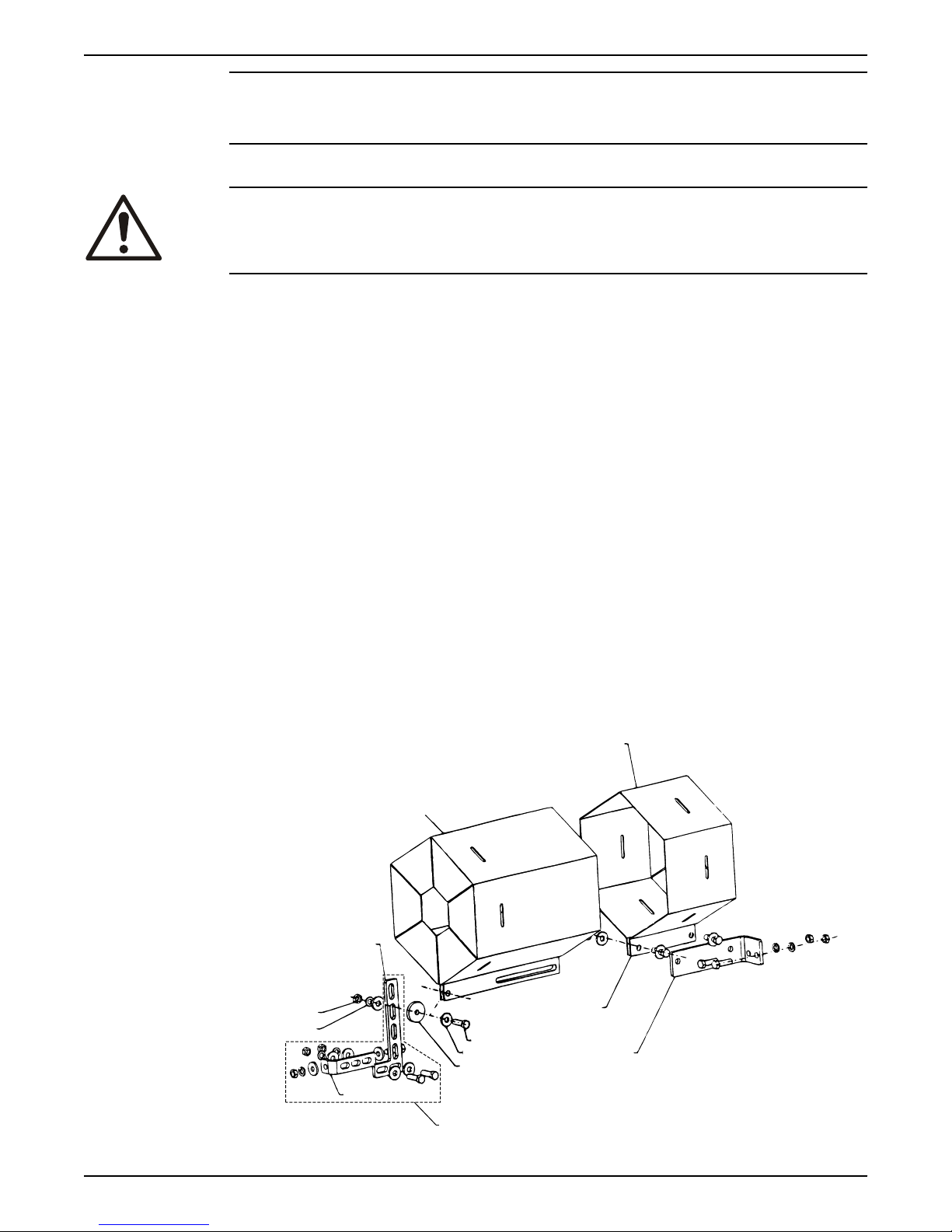
6.6.3 Remove the hex coupling guard
1. Remove the two capscrews that hold the outer (motor side) coupling guard to the
support brackets.
2. Spread the outer guard apart and pull it off the inner guard.
Do not spread the outer and inner guards more than necessary to remove the guard. It
could alter their fit and appearance.
3. Remove the capscrew that holds the inner guard to the support bracket.
4. Spread the inner guard apart and pull it over the coupling.
32 G&L Pumps Series A-C 9100 Base Mounted Centrifugal Pumps INSTRUCTION MANUAL
Page 35

1. Outer guard
2. Inner guard
3. Attach the support bracket inline with the bolt
4. Support bracket
5. Nut
6. Lockwasher
7. Capscrew
8. Flat washer
9. Spacer washer
10.Option used instead of the spacer where overall guard length exceeds 12 in. (30 cm) or
the guard width is over 10 in. (25 cm) across the flats
11.Locate the support arm between the outer guard ends. Align the arm with holes in the
outer guard and holes in the saddle bracket.
12.Motor saddle bracket attached to the motor saddle
Figure 20: Hex guard exploded view for typical installation
6.6.4 Disassemble the pump with packing on shaft sleeve
See Parts list chapter for exploded view of the pump.
1. Close valves on suction and discharge sides of the pump. If no valves have been
installed, it will be necessary to drain the system.
2. Remove coupling guard and disconnect coupling. Refer to instructions on how to
remove the hex coupling guard.
3. Loosen the cap screws which secure the coupler flanges to the coupler hubs. Remove
the coupler flanges and sleeve by compressing the flanges and pulling out from
beneath the hubs or by loosening the allen set screws and sliding the hubs back on
the shafts. Remove the coupler hub from the pump shaft.
4. Drain the pump by opening the vent plug (0–910–0) and remove drain plugs (0–910–0)
on suction and discharge nozzle.
5. Remove seal lines (0–901–0, 0–950–0, 0–952–0), if supplied.
6. Remove gland bolts (3–904–9), washers (1–909–9) and slide gland (3–014–2) away from
casing.
7. Remove all casing main joint capscrews (2–904–1) and dowels (2–916–9). Use slot in
casing main joint and separate the casing halves with a pry bar. Lift upper half casing
(2–001–7) by cast lugs.
8. Remove packing (1–924–9) and seal cage (1–013–2) from each stuffing box.
9. Remove cap screws (1–904–9) which hold bearing housings (3–025–2) to the casing
and lift rotating element out of lower casing (2–001–08). Rotating element may now be
moved to a suitable working location.
10.Pull coupling half and key (3–911–2) off shaft (3–007–0).
NOTE: A spare rotating element can be installed at this point.
11.Remove cap screws (3–904–9) from bearing covers (3–018–3, 4).
12.Remove bearing housings (3–025–2), locknut (3–516–4), and lockwasher (3–517–4).
Mount bearing puller and remove bearings (3–026–2). Remove thrust washer (3–078–9)
and snap ring (3–915–9).
NOTE: Locknut, lockwasher, and thrust washer are not on inboard side.
IMPORTANT: Do not reuse the ball bearings.
13.Remove bearing covers (3–018–5, 4) and push oil seals (3–177–9) out of bearing covers
and coupling and bearing housing. Pull deflectors (3–136–9) off shaft.
14.Remove casing rings (3–003–9) from impellers (4–002–0).
15.Remove set screw (3–902–9) from shaft nuts. Remove shaft nuts (3–015–9), O-rings (3–
914–9), sleeves (3–009–9), sleeve gaskets (1–428–1), and impeller (4–002–0).
NOTE: Apply heat uniformly to the shaft sleeve to loosen the sealant between the shaft
and sleeve. DO NOT HEAT ABOVE 275°F. To further assist in removing the sleeves,
6 Maintenance
G&L Pumps Series A-C 9100 Base Mounted Centrifugal Pumps INSTRUCTION MANUAL 33
Page 36
6 Maintenance
hold the shaft vertically and drop it on a block of wood. The impeller weight should
force both the impeller and sleeve from the shaft.
16.For impellers with replaceable rings, remove the rings (4–004–9) by cutting the rings
with a cold chisel.
For pumps equipped with adjustable rings, refer to Adjustable wear rings instructions.
6.7 Pre-assembly inspections
Guidelines
Before you assemble the pump parts, make sure you follow these guidelines:
• Inspect the pump parts according to the information in these pre-assembly topics
before you reassemble your pump. Replace any part that does not meet the required
criteria.
• Make sure that the parts are clean. Clean the pump parts in solvent in order to remove
oil, grease, and dirt.
NOTICE:
Protect machined surfaces while you clean the parts. Failure to do so may result in
equipment damage.
6.7.1 Replacement guidelines
Impeller replacement
This table shows the criteria for replacing the impeller:
Impeller parts When to replace
Impeller vanes • When grooved deeper than 1/16 in. (1.6 mm), or
Vane edges When you see cracks, pitting, or corrosion damage
Gaskets, O-rings, and seats replacement
• Replace all gaskets and O-rings at each overhaul and disassembly.
• Inspect the seats. They must be smooth and free of physical defects.
• Replace parts if the seats are defective.
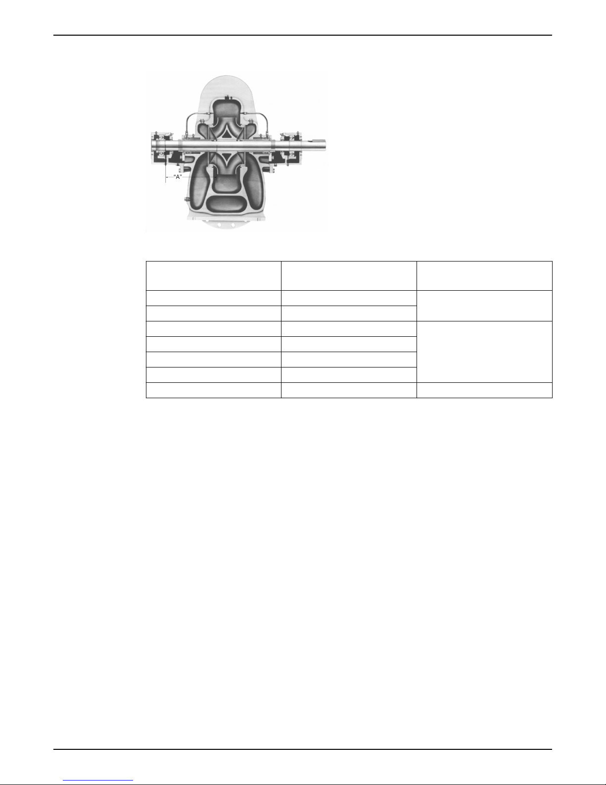
6.7.2 Shaft and sleeve inspection
Inspection criteria
Inspect the shaft and sleeve according to this criteria:
• Thoroughly clean the shaft and sleeve.
• Thoroughly clean the coverplate seal cavity.
• Inspect the surface for damage such as pitting, corrosion, nicks, and scratches.
Replace these parts if they are damaged.
• When worn evenly more than 1/32 in. (0.8 mm)
34 G&L Pumps Series A-C 9100 Base Mounted Centrifugal Pumps INSTRUCTION MANUAL
Page 37
6.8 Dimensions
Figure 21: Cross section
6 Maintenance
Pump size
12x8x22M 25
12x8x22L 26
14x10x20S 26
16x12x23 26
16x14x17 24
18x14x23 32
14x10x20L 26 16.60
Quantity
2–904–9
6.9 Reassembly
6.9.1 Reassemble the pump with the mechanical seals on the shaft sleeve
All bearings, O-rings, seals, and gaskets should be replaced with new parts during
assembly. All reusable parts should be cleaned of all foreign matter before reassembling.
The main casing joint gasket should be made using the upper half as a template. Lay the
gasket material on the casing joint and mark it by pressing it against the edges of the
casing. Trim the gasket so that it is flush with the inside edges of the casing.
1. Place impeller key (3–911–1) in shaft (3–007–0).
2. Check the impeller (4–002–0) and casing to determine the correct impeller rotation
and locate the impeller on the shaft per dimension “A” given in table.
NOTE: For impellers with replaceable rings, heat each new ring(4–004–9) and slide it
onto the impeller. Hold the rings against the impeller shoulder until they cool.
3. Place both shaft sleeve keys (3–911–3) on shaft (3–007–0).
4. Slide sleeve gaskets (1–428–1) onto shaft and against hub of impeller.
5. Slide sleeves (3–009–9) onto shaft.
6. Place the sleeve O-ring (3–914–9) onto the shaft, into the sleeve counterbore. Verify
that Dimension “A” is maintained. Using a pin spanner wrench and hammer, securely
tighten the shaft sleeve nuts (3–015–9). Then, drill a shallow recess in the shaft through
the set screw hole in each of the shaft nuts. Lock each shaft sleeve nut in position with
cup point set screws (3–902–9). A low strength sealant, such as Loctite 271, can be
used to retain set screws.
Dimension A
13.50
15.81
G&L Pumps Series A-C 9100 Base Mounted Centrifugal Pumps INSTRUCTION MANUAL 35
Page 38
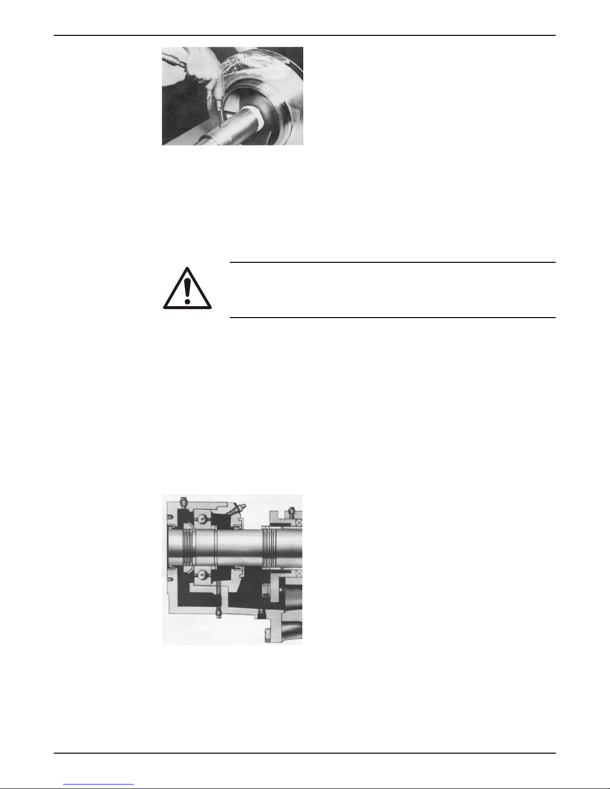
6 Maintenance
7. Assemble casing rings (3–003–9). See figure for adjustable rings.
8. Install stationary seats (3–401–0) onto the glands (3–014–2) with lapped surface facing
outward. Do not scratch or damage seal faces during assembly.
Stationary seat must bottom squarely in gland.
9. Apply fine coat of silicon grease or equivalent to shaft sleeve, and slide seal head
assembly (3–402–0) over sleeve. If seal is a John Crane Type 8, set to approximate
dimension shown and tighten set screws. Next, install O-rings (3–914–2) onto glands
(3–014–2) and install glands on shaft.
CAUTION:
Do not use petroleum-based products for installing the mechanical seal
head as it may attack the rubber elastomers.
10.Start heating bearings (3–026–2) so that they will be ready when called for the next
step. Use dry heat from induction heat lamps or electric furnace, or a 10–15% soluble
oil and water solution.
IMPORTANT: Do not exceed 275°F.
These are precision, high-quality bearings. Exercise care always to keep them clean
and free from foreign matter.
11.Assemble oil seal (3–177–9) in each bearing cover. Install gaskets (30409–9) on each
bearing cover.
NOTE: Seal lip or pressure side of oil seal must point towards the ends of the shaft that
the oil seal is assembled on. See oil lubricated bearings.
The following figures show a grease lubricated bearing housing and an oil lubricated
bearing housing, respectively. The main difference between the two is the grease
fitting and the oil ring, respectively.
Figure 22: Grease lubricated bearing housing
36 G&L Pumps Series A-C 9100 Base Mounted Centrifugal Pumps INSTRUCTION MANUAL
Page 39
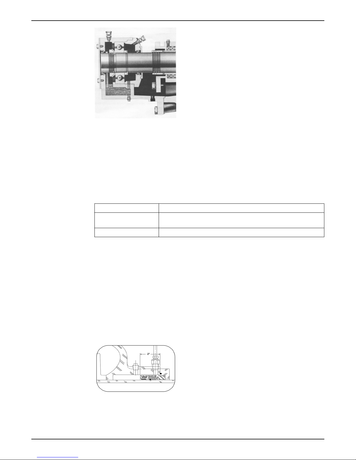
6 Maintenance
Figure 23: Oil lubricated bearing housing
12.Slide deflectors (3–136–9) and bearing covers (3–018–3), –4) on the shaft. Install snap
rings (3–915–9). Install thrust washer (3–078–9) on the outboard end.
For ease of assembly and protection of rubber parts while sliding parts onto shaft,
cover O-ring groove, keyways, and threads with electrical tape.
NOTE: Inboard bearing cover (3–018–3) is approximately 1/4 inch less in width than
the outboard bearing cover (3–018–4). This is the only dimensional difference.
13.Press heated bearing (3–026–2) on shaft against snap ring or thrust washer. Install
locknut (3–516–4) and lock washer (3–517–4) on outboard end. Make certain the
locknut is secured and then bend over tab on lock washer.
14.
Condition Action
Pumps with grease lubrication Cool bearings at room temperature and coat with 2 ounces or 3 ounces of a
recommended grease.
Pumps with oil lubrication Refer to instructions for installation of oil lubricated parts.
15.Assemble oil seals (3–177–9) in each bearing housing. Refer to NOTE under number
11 for direction of oil seal.
16.Slide bearing housings (3–025–2) over bearings (3–026–2).
17.Assemble bearing cover to bearing housing with two capscrews (3–904–9).
18.Replace pump coupling half and key (3–911–2).
19.Assemble rotating element in lower half casing (2–001–8). Correctly locate casing ring
pins (3–943–9) in casing main joint slot.
NOTE: Sliding inboard bearing housing toward coupling before assembling rotating
element in casing will ease assembly.
20.Bolt outboard bearing housing in place. Be sure that both housings are seated in lower
half casing.
21.Bolt inboard bearing housing in place. If seal is a John Crane Type 8, set seal to
dimension shown and tighten set screws.
22.Clean the gasket surfaces of the casing. Apply Scotch 3M-77 spray adhesive or
equivalent to the lower half of the casing.
23.Within one minute of spraying, set the gaskets (2–123–5, –6) in place on the lower half
casing. Align the holes in the gaskets with the holes in the casing and press the gaskets
firmly against the lower half casing face in the area coated by the adhesive.
G&L Pumps Series A-C 9100 Base Mounted Centrifugal Pumps INSTRUCTION MANUAL 37
Page 40
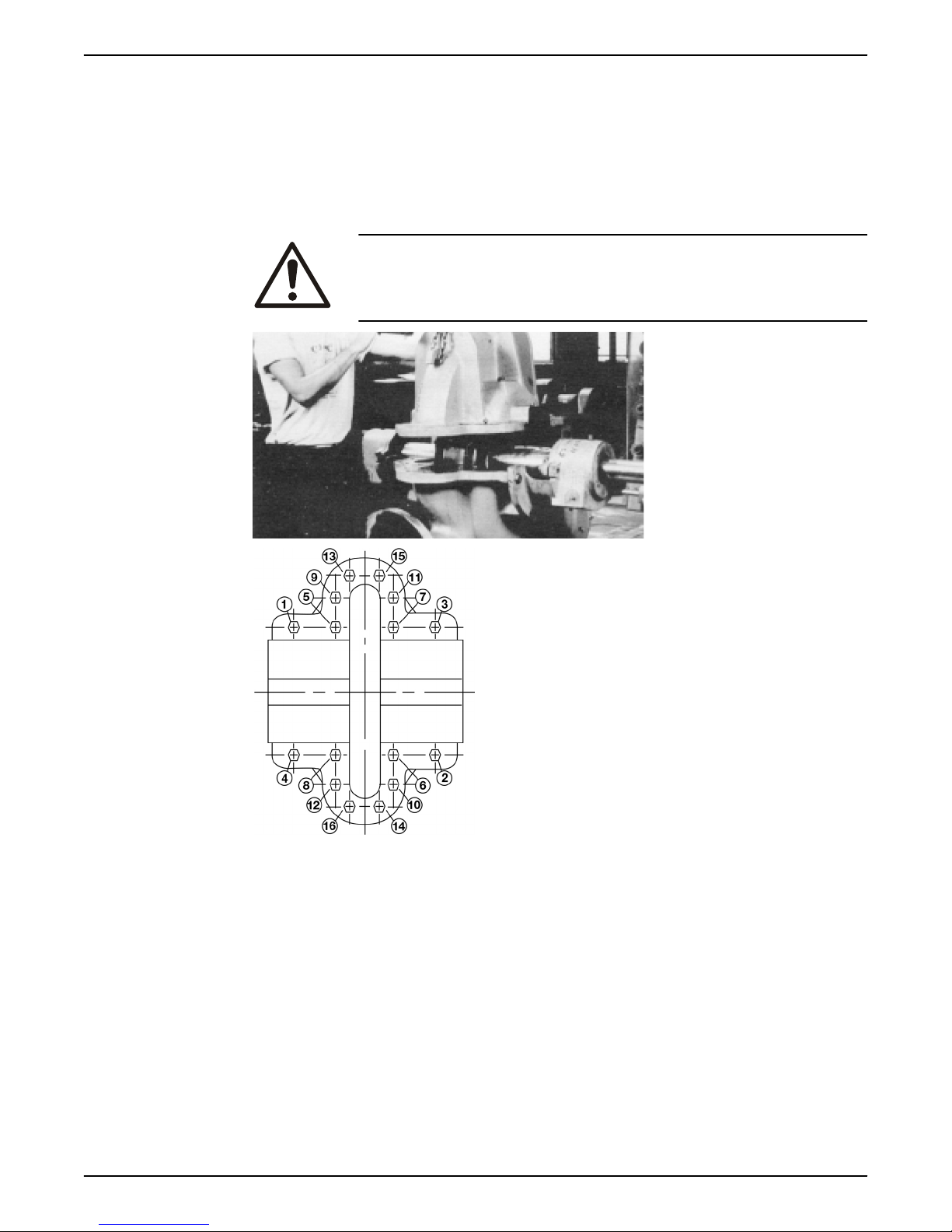
6 Maintenance
24.Lower upper half casing (2–001–7) into place and locate using the taper dowels (2–
916–9) and install casing main joint bolts (2–904–9). The casing joint bolts should be
tightened to the following torques: 300 ft-lb minimum for .75"-10 Ferry Cap
Counterbore screws (Grade 8), 400 ft-lb minimum for 1.0”-8 Ferry Cap Counterbore
screws (Grade 8). Refer to bolt torque pattern. Before tightening bolt, be sure that
taper dowels are seated properly in reamed holes.
NOTE: Torque valves are essential in obtaining proper gasket compression so no
leakage can occur at main joint.
CAUTION:
Double check rotation of pump before installing the upper half casing.
Figure 24: Bolt torquing pattern
25.Slide deflectors (3–136–9) toward bearing covers. Allow rotating clearance of
approximately 1/16”.
26.Rotate shaft by hand to assure that it turns smoothly and is free from rubbing and
binding.
27.Bolt glands (3–014–2) to casing with gland bolts (3–904–9).
28.Assemble seal water lines (0–901–0, 0–950–0, 0–052–0) to stuffing box and casing. Seal
water lines go to outside holes. Refer to Dimension section for more information.
29.Check coupling alignment and redowel if necessary.
6.9.2 Reassemble the pump with the packing on the shaft sleeve
All bearings, O-rings, seals, and gaskets should be replaced with new parts during
assembly. All reusable parts should be cleaned of all foreign matter before reassembling.
The main casing joint gasket should be made using the upper half as a template. Lay the
38 G&L Pumps Series A-C 9100 Base Mounted Centrifugal Pumps INSTRUCTION MANUAL
Page 41

6 Maintenance
gasket material on the casing joint and mark it by pressing it against the edges of the
casing. Trim the gasket so that it is flush with the inside edges of the casing.
1. Place impeller key (3–911–1) in shaft (3–007–0).
2. Check the impeller (4–002–0) and casing to determine the correct impeller rotation
and locate the impeller on the shaft per dimension “A” given in “Dimensions” table.
NOTE: For impellers with replaceable rings, heat each new ring (4–004–9) and slide it
onto the impeller. Hold the rings against the impeller shoulder until they cool.
3. Place both shaft sleeve keys (3–911–3) an shaft (3–007–0).
4. Slide sleeve gaskets (1–428–1) onto shaft and against hub of impeller.
5. Slide sleeves (3–009–9) onto shaft.
6. Place the sleeve O-ring (3–914–9) onto the shaft, into the sleeve counterbore. Verify
that Dimensions “A” is maintained. Using a pin spanner wrench and hammer, securely
tighten the shaft sleeve nuts (3–015–9). Then, drill a shallow recess in the shaft through
the set screw hole in each of the shaft nuts. Lock each shaft sleeve nut in position with
cup point set screws (3–902–9). A low strength sealant, such as Loctite 271, can be
used to retain set screws.
7. Assemble casing rings (3–003–9). See figure for adjustable rings.
8. Start heating bearings (3–026–2) so that they will be ready when called for in the next
step. Use dry heat from induction heat lamps or electric furnace, or a 10–15% soluble
oil and water solution.
IMPORTANT: Do not exceed 275°F.
These are precision, high-quality bearings. Exercise care always to keep them clean
and free from foreign matter.
9. Assemble oil seal (3–177–9) in each bearing cover. Install gaskets (3–409–9) on each
bearing cover.
NOTE: Seal lip or pressure side of oil seal must point towards the ends of the shaft that
the oil seal is assembled on. See oil lubricated bearings. See figures 18 and 19 to show
a grease lubricated bearing housing and an oil lubricated bearing housing,
respectively.
10.Slide deflectors (3–136–9) and bearing covers (3–018–3, –4) on the shaft. Install snap
rings (3–915–9). Install thrust washer (3–078–9) on the outboard end. For ease of
assembly and protection of rubber parts while sliding parts onto shaft, cover O-ring
groove, keyways, and threads with electrical tape.
NOTE: Inboard bearing cover (3–018–3) is approximately 1/4 inch less in width than
the outboard bearing cover (3–018–4). This is the only dimensional difference.
11.Press heated bearing (3–026–2) on shaft against snap ring or thrust washer. Install
locknut (3–516–4) and lock washer (3–517–4) on outboard end. Make certain the
locknut is secured and then bend over tab on lock washer.
12.
Condition Action
Pumps with grease lubrication Cool bearings at room temperature and coat with 2
ounces or 3 ounces of a recommended grease.
Pump with oil lubrication Refer to instructions for installation of oil lubricated
parts.
13.Assemble oil seals (3–177–9) in each bearing housing. Refer to NOTE under number 9
for direction of oil seal.
14.Slide bearing housings (3-025-2) onto shaft (3-007-0) over bearings (3-026-2)
15.Assemble bearing cover to bearing housing with two capscrews (3–904–9).
16.Replace pump coupling half and key (3–911–2).
17.Assemble rotating element in lower half casing (2–001–8). Correctly locate casing ring
pins (3–943–9) in casing main joint slot.
G&L Pumps Series A-C 9100 Base Mounted Centrifugal Pumps INSTRUCTION MANUAL 39
Page 42

6 Maintenance
NOTE: Sliding inboard bearing housing toward coupling before assembling rotating
element in casing will ease assembly.
18.Bolt outboard bearing housing in place. Be sure that both housings are seated in lower
half casing.
19.Bolt inboard bearing housing in place.
20.Clean the gasket surfaces of the casing. Apply Scotch 3M-77 spray adhesive or
equivalent to the lower half of the casing.
21.Within one minute of spraying, set the gaskets (2–123–5, –6) in place on the lower half
casing. Align the holes in the gaskets with the holes in the casing and press the gaskets
firmly against the lower half casing face in the area coated by the adhesive.
22.Lower upper half casing (2–001–7) into place and locate using the taper dowels (2–
916–9) and install casing main joint bolts (2–904–9). The casing joint bolts should be
tightened to the following torques: 300 ft-lb minimum for .75”-10 Ferry Cap
Counterbore screws (Grade 8), 400 ft-lb minimum for 1.0”-8 Ferry Cap Counterbore
screws (Grade 8). Refer to bolt torque pattern (Figure 20). Before tightening bolt, be
sure that taper dowels are seated properly in reamed holes.
NOTE: Torque valves are essential in obtaining proper gasket compression so no
leafage can occur at main joint.
CAUTION: Double-check rotation of pump before installing the upper half casing.
23.Slide deflectors (3–136–9) toward bearing covers. Allow rotating clearance of
approximately 1/16”.
24.Rotate shaft by hand to assure that it turns smoothly and is free from rubbing and
binding.
25.Cut full rings of 5/8 inch square packing so that ends butt, leaving no gap between
packing and casings. Install three rings of packing (1–924–9) and tap fully to bottom of
both stuffing boxes. (See figure below) Stagger joints of each ring of packing at least
90 degrees. Install seal cage (1–013–2) and be sure that it will line up with seal water
inlet when packing is compressed. Install remaining three rings of packing with joints
staggered.
26.Assemble glands (1–014–2) square with stuffing box and pull tight. Then loosen gland
bolts (1–904–9) to permit packing to expand and retighten finger tight. Final
adjustment of gland bolts must be done when pump is running.
27.Assemble seal water lines (0–901–0, 0–950–0, 0–952–0) to stuffing box and casing. Seal
water lines go to outside holes. Refer to Dimension section for more information.
28.Check coupling alignment and redowel if necessary.
40 G&L Pumps Series A-C 9100 Base Mounted Centrifugal Pumps INSTRUCTION MANUAL
Page 43

6.9.3 Install the hex coupling guard
1 2 3
6 5 4
1. Slide the inner guard into the outer guard.
2. Spread the guards and place them over the coupling.
Do not spread the inner and outer guards more than necessary for guard installation,
as it can alter their fit and appearance.
3. Straddle the support bracket with the guards and install a capscrew through the hole
in the support bracket and guard located closest to the pump.
Do not tighten the capscrew.
4. Install the outer guard capscrews according to the directions in this table.
If... Then...
The pump has a motor saddle
support bracket
The pump does not have a motor
saddle support bracket
5. Position the outer guard so that there is less than 1/4 in. (0.64 cm) of exposed shaft.
6. Hold the guard in this position and tighten the three capscrews.
7. Open the isolation valves and inspect the pump for leaks.
8. Return the pump to service if it is not leaking.
6 Maintenance
Ensure that the outer guard straddles the support arm and install the two
remaining capscrews.
Do not tighten the capscrews.
Insert the spacer washer between the holes located closest to the motor in
the outer guard and install the two remaining capscrews.
Do not tighten the capscrews.
6.9.4 Adjustable wear rings
Adjustable rings are an assembly of two threaded rings. The outer, stationary ring is held
in the casing by a flange and an anti-rotation pin in the lower half main joint. The inner,
adjustable ring can be moved axially, in either direction, by rotating it. The ring is held in
position by a stainless steel locking pin. All rings have clockwise threads.
Adjustment
When the clearance between the impeller wear face and the adjustable wearing ring
becomes excessive; For example, approximately .020” to .030”.
1. Remove the upper half casing and pull the locking pin.
2. Rotate the inner rings clockwise to restore .005” to .008” clearance greater than shaft
end float between the ring and the impeller.
3. Drill a new hole in the inner ring for the locking pin. This is a blind hole, do not drill
through.
4. Replace the locking pin and upper half casing.
1. Sleeve
2. Impeller ring
3. Casing ring
G&L Pumps Series A-C 9100 Base Mounted Centrifugal Pumps INSTRUCTION MANUAL 41
Page 44

11
2
3
4
5
6 Maintenance
4. Impeller
5. Casing
6. Locking pin
Disassembly and reassembly
Adjustable rings are removed in the same manner as standard casing rings. They can be
separated for cleaning. Adjustable rings are installed in the pump with stationary and the
adjustable members assembled but not pinned.
1. Turn the adjustable member counterclockwise to provide maximum impeller
clearance and slide over shaft ends.
– With the rotating element in pump, the ring can be adjusted. Be sure that stationary
member has its flange flush against casing lower half.
2. Move rotating element toward outboard as far as bearings permit.
3. Screw outboard end adjustable ring toward impeller to obtain .005” to .006” axial
impeller clearance.
4. Drill through stationary ring hole into adjustable ring and insert locking pin.
5. Move rotating element toward coupling and set coupling end ring in the same
manner.
6.9.5 Install the oil ring
1. Place the oil ring in the bearing housing, directly under the pipe plug hole.
2. Run a wire through the pipe plug hole, around the oil ring and back through the pipe
plug hole once again.
3. Tie the wire to a metal washer (being a larger diameter than the hole) causing the oil
ring to become tight against the inside top of the bearing housing.
4. Assemble the bearing housing over the bearing.
5. Untie the wire. The oil ring will drop down onto the shaft.
6. Check the position of the oil ring through the pipe plug hole at the top of the bearing
housing.
The oil ring must be resting on the shaft for correct operation. A screwdriver can be
used to correct the oil ring position, if necessary.
6.9.6 Change the oil for oil lubricated bearings
1. Reservoir
2. Vent assembly
3. Bearing housing
4. Pipe plug
5. Lower casting
Figure 25: Oiler assembly
1. Remove the vent assembly from the top of the bearing housing.
2. Remove the pipe plug from the bottom of the bearing housing.
42 G&L Pumps Series A-C 9100 Base Mounted Centrifugal Pumps INSTRUCTION MANUAL
Page 45

3. Unscrew the reservoir and remove.
1 2
34
5
4. Flush the oiler and bearing housing with a light grade of oil. Flush until all foreign
particles have been removed.
5. Screw the pipe plug and vent assembly back into place.
6. Fill the reservoir with a good grade filtered mineral oil.
Refer to oil lubrication instructions given previously in this manual for type of oil.
NOTE: You must fill through Trico reservoir.
7. Place thumb over reservoir spout, invert and place reservoir on lower casting while
removing thumb. Allow reservoir to empty, filling the bearing housing.
Several fillings of the reservoir may be required before the actual level is reached. No
more oil will run out of the reservoir.
8. When reservoir stays full, screw reservoir back into lower casting.
A periodic filling of the reservoir is required. When the oil becomes dirty, repeat steps 1
through 8.
6.9.7 Limited end float coupling
For units with drivers having sleeve bearings, the coupling halves are set to limited total
shaft axial movement to less than one-half of the motor rotor assembly end float. This is
accomplished by inserting a phenolic disc, or equivalent, of a specified thickness between
the motor and pump shaft.
6 Maintenance
1. Cover
2. Phenolic disc
3. Pump shaft
4. Motor shaft
5. Hub
Figure 26: Limited end float coupling arrangement
For pump installations that use limited end float gear type couplings:
1. Slip fit the coupling hubs onto the pump and motor shafts.
2. Install the coupling covers and hubs.
3. With the motor set on its Magnetic Center, butt the pump and motor shafts with the
Once the above instructions have been followed out copletely, the Alignment Procedures
should be followed.
6.9.8 Assembly references
6.9.8.1 Ordering parts
The pumps covered by this manual have been designed and built with certain
replaceable wearing parts. The recommended inventory of spare parts depends upon the
installation and the importance of continued operation.
For critical service requiring a minimum of “down time” a complete or “quick change”
rotating element is recommended.
phenolic disc inserted between them.
– The pump thrust bearing limits end float towards the motor.
– The thrust bearing of the pump is large enough to carry any magnetic thrust
developed by the motor when aligned properly.
G&L Pumps Series A-C 9100 Base Mounted Centrifugal Pumps INSTRUCTION MANUAL 43
Page 46

6 Maintenance
For normal service, with repairs to be made in the field, the following parts are
recommended for stock.
• 1 set of bearings
• 1 set of wearing rings
• 1 set of gaskets, O-rings, and grease seals
• 2 mechanical seals (complete), or 2 sets of packing (if provided)
• 1 set of shaft sleeves
Parts should be ordered as far in advance of their use as possible since circumstances
beyond the control of the company may reduce existing stock. Not all parts are stocked
and must be manufactured for each order.
To facilitate rapid handling of your order for spare parts, be sure to include the following
information:
1. Serial number of the pump.
2. Catalog number of the part.
3. Quantity of each part.
4. Name of the part.
5. Material desired. (Parts will be furnished in original materials unless specified as a
material change. All material substitutions should be discussed with the factory.
6.9.8.2 Screw torque values
Capscrew torque in ft-lb (Nm)
Capscrew
type
SAE grade
2
Brass and
stainless
steel
SAE grade
5
Head
marking
or 4 (5) 10 (14) 17 (23) 27 (37) 42 (57) 83 (113) 130 (176) 200 (271) 300 (407)
1/4 5/16 3/8 7/16 1/2 5/8 3/4 7/8 1
6 (8) 13 (18) 25 (34) 38 (52) 60 (81) 120 (163) 190 (258) 210 (285) 300 (407)
10 (14) 20 (27) 35 (47) 60 (81) 90 (122) 180 (244) 325 (440) 525 (712) 800 (1085)
*The M6 set screw has a rating of 10 N m.
6.9.8.3 Dealer servicing
If trouble occurs that cannot be rectified, contact your local sales and service
representative and be prepared to provide this information:
1. Complete nameplate data of pump and motor
2. Suction and discharge pipe pressure gauge readings
3. Ampere draw of the motor
4. A sketch of the pump hook-up and piping
Capscrew diameter (in inches)
44 G&L Pumps Series A-C 9100 Base Mounted Centrifugal Pumps INSTRUCTION MANUAL
Page 47

7 Troubleshooting
7.1 Operation troubleshooting
Between regular maintenance inspections, be alert for signs of motor or pump trouble.
Correct any trouble immediately and avoid costly repair and shutdown.
Symptom Cause Remedy
Lack of prime Fill pump and suction pipe
Loss of prime Check for leaks in suction pipe joints
Suction lift too high. If no obstruction at inlet, check for
No liquid delivered
Discharge head too high. Check pipe friction losses. Large
The motor speed is too low. Check whether motor is directly
Wrong direction of rotation. Check motor rotation with directional
Impeller completely plugged. Dismantle pump and clean impeller.
7 Troubleshooting
completely with liquid.
and fittings; vent casing to remove
accumulated air.
pipe friction losses. Static lift may be
too great. Measure with mercury
column or vacuum gauge while
pump operates. If static lift is too
high, liquid to be pumped must be
raised or pump lowered.
piping may correct condition. Check
that valves are wide open.
across-the-line and receiving full
voltage. Or frequency may be too low;
motor may have an open phase.
arrow on pump casing.
G&L Pumps Series A-C 9100 Base Mounted Centrifugal Pumps INSTRUCTION MANUAL 45
Page 48
7 Troubleshooting
Symptom Cause Remedy
Air leaks in suction piping If liquid pumped is water or other
non-explosive, and explosive gas or
dust is not present, test flanges for
leakage with flame or match, or by
plugging inlet and putting line under
pressure. A gauge will indicate a leak
with a drop of pressure.
The motor speed is too low. Check whether motor is directly
across-the-line and receiving full
voltage. Or frequency may be too low;
motor may have an open phase.
Discharge head too high Check pipe friction losses. Large
piping may correct condition. Check
that valves are wide open.
Suction lift too high If no obstruction at inlet, check for
pipe friction losses. Static lift may be
too great. Measure with mercury
column or vacuum gauge while
pump operates. If static lift is too
high, liquid to be pumped must be
raised or pump lowered.
Impeller partially plugged Dismantle pump and clean impeller.
Not enough liquid being delivered
Cavitation; insufficient NPSH
(depending on installation)
1. Increase positive suction head on
pump by lowering pump.
2. Sub-cool suction piping at inlet to
lower entering liquid
temperature.
3. Pressurization suction vessel.
Defective impeller. Inspect impeller, bearings and shaft.
Replace is damaged or vane sections
badly eroded.
Foot valve too small or partially
obstructed.
Area through ports of valve should be
at least as large as area of suction
pipe — preferable 1½ times. If
strainer is used, net clear area should
be 3 to 4 times area of suction pipe.
Suction inlet not immersed deep
enough.
If inlet cannot be lowered, or if eddies
through which air is sucked persist
when it is lowered, chain a board to
suction pipe. It will be drawn into
eddies, smothering the vortex.
Too small impeller diameter.
Probable cause if none of above)
Check with factory to see if a larger
impeller can be used; otherwise, cut
pipe losses or increase speed — or
both, if needed. Be careful not to
seriously overload drive.
46 G&L Pumps Series A-C 9100 Base Mounted Centrifugal Pumps INSTRUCTION MANUAL
Page 49

Symptom Cause Remedy
Mechanical defects See “Defective impeller” and “Foot
valve too small or partially
obstructed”.
Obstruction in liquid passages. Dismantle pump and inspect
passages of impeller and casing.
Remove obstruction.
Not enough pressure
Air or gases in liquid. (Test in
laboratory, reducing pressure on
liquid to pressure in suction line.
Watch for bubble formation.)
May be possible to over rate pump to
point where it will provide adequate
pressure despite condition. Better to
provide gas separation chamber on
suction line near pump, and
periodically exhaust accumulated
gas. See “Cavitation; insufficient
NPSH”.
Too small impeller diameter.
(Probable cause if none above.)
Check with factory to see if a larger
impeller can be used; otherwise, cut
pipe losses or increase speed — or
both, if needed. Be careful not to
seriously overload drive.
Incomplete priming. Free pump, piping and valves of all
air. If high points in suction prevent
this, they need correcting.
Suction lift too high. If no obstruction at inlet, check for
pipe friction losses. Static lift may be
too great. Measure with mercury
column or vacuum gauge while
pump operates. If static lift is too
high, liquid to be pumped must be
raised or pump lowered.
Air leaks in suction piping. If liquid pumped is water or other
Pump operates for short time, then
stops
non-explosive, and explosive gas or
dust is not present, test flanges for
leakage with flame or match, or by
plugging inlet and putting line under
pressure. A gauge will indicate a leak
with a drop of pressure.
Air or gasses in liquid. May be possible to over rate pump to
point where it will provide adequate
pressure despite condition. Better to
provide gas separation chamber on
suction line near pump, and
periodically exhaust accumulated
gas. See “Cavitation; insufficient
NPSH”.
Head lower than rating; thereby
pumping too much liquid.
Machine impeller’s OD to size
advised by factory.
Cavitation 1. Increase positive suction head on
pump by lowering pump.
2. Sub-cool suction piping at inlet to
Pump takes too much power
lower entering liquid
temperature.
3. Pressurization suction vessel.
Mechanical defects See “Defective impeller” and “Foot
valve too small or partially
obstructed”.
7 Troubleshooting
G&L Pumps Series A-C 9100 Base Mounted Centrifugal Pumps INSTRUCTION MANUAL 47
Page 50

7 Troubleshooting
Symptom Cause Remedy
Suction inlet not immersed enough. If inlet cannot be lowered, or if eddies
through which air is sucked persist
when it is lowered, chain a board to
suction pipe. It will be drawn into
eddies, smothering the vortex.
Liquid heavier (in either viscosity or
specific gravity) than allowed for.
Use larger driver. Consult factory for
recommended size. Test liquid for
viscosity and specific gravity.
Wrong direction of rotation. Check motor rotation with directional
arrow on pump casing.
Casing distorted by excessive strains
from suction or discharge piping.
Check alignment. Examine pump for
friction between impeller and casing.
Replace damaged parts.
Shaft bent due to damage — through
shipment, operation, or overhaul.
Check deflection of rotor by turning
on bearing journals. Total indicator
run-out should not exceed 0.002 on
shaft and 0.004 on impeller wearing
surface.
Mechanical failure of critical pump
parts.
Check bearings and impeller for
damage. Any irregularity in these
parts will cause a drag on shaft.
Misalignment Realign pump and driver.
Speed may be too high (brake hp of
Check voltage on motor.
pump varies as the cube of the speed;
therefore, any increase in speed
means considerable increase in
power demand).
Electrical defects. The voltage and frequency of the
electrical current may be lower than
that for which the motor was built; or
there may be defects in motor. The
motor may not be ventilated properly
due to poor location.
Mechanical defects in turbine, engine
or other type of drive exclusive of
If trouble cannot be located, consult
factory.
motor.
48 G&L Pumps Series A-C 9100 Base Mounted Centrifugal Pumps INSTRUCTION MANUAL
Page 51
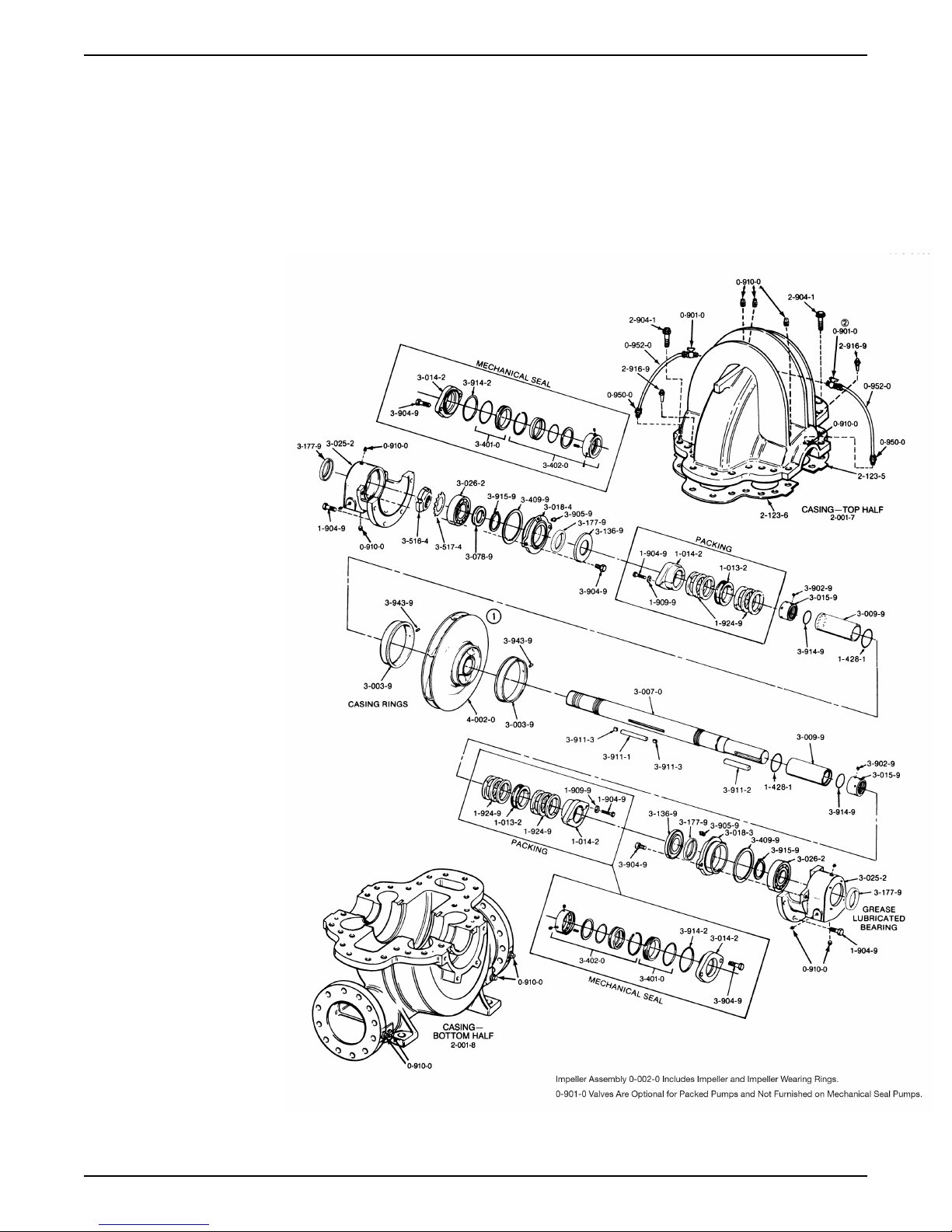
8 Parts Listings and Cross-Sectional Drawings
8 Parts Listings and Cross-Sectional
Drawings
8.1 Parts list
G&L Pumps Series A-C 9100 Base Mounted Centrifugal Pumps INSTRUCTION MANUAL 49
Page 52

8 Parts Listings and Cross-Sectional Drawings
Part number Part name
Quantity
Packing Mechanical seal
0–901–0 Valve 2 (optional) 2
0–910–0 Pipe plug 20 18
0–950–0 Pipe nipple 2 (optional) 2
0–952–0 Tubing 2 (optional) 2
1–013–2 Seal cage 2
1–014–2 Gland (packing) 2
1–428–1 Sleeve gasket 2 2
1–904–9 Gland and housing bolt 12 8
1–909–9 Washer, gland bolt 4
1–924–9* Packing ring 12
2–001–7 Casing, upper half 1 1
2–001–8 Casing, lower half 1 1
2–123–5* Casing, joint gasket
1 1
(suction)
2–133–6* Casing joint gasket
1 1
(discharge)
2–904–1 Cap screw (casing) Varies with pump size Varies with pump size
2–916–9 Taper pin 2 2
3–003–9* Casing ring 2 2
3–007–0 Shaft 1 1
3–009–9* Shaft sleeve 2 2
3–014–2 Gland (mechanical seal) 2
3–015–9 Shaft sleeve nut 2 2
3–018–3 Bearing housing cover
1 1
(inboard)
3–018–4 Bearing housing cover
1 1
(outboard)
3–025–2 bearing housing 2 2
3–026–2* Bearing 2 2
3–078–9 Thrust washer (outboard) 1 1
3–136–9 Deflector 2 2
3–177–4* Lip seal (outboard bearing) 1 1
3–177–9* Lip seal (bearing) 3 3
3–401–0* Mechanical seal seat 2
3–402–0* Mechanical seal head 2
3–409–9 Gasket (bearing housing
2 2
cover)
3–516–4 Locknut 1 1
3–517–4 Lockwasher 1 1
3–902–9 Set screw (shaft sleeve nut) 2 2
3–904–9 Gland and cover bolt 4 8
3–911–1 Key (impeller) 1 1
3–911–2 Key (coupling) 1 1
3–911–3 Key (shaft sleeve) 2 2
50 G&L Pumps Series A-C 9100 Base Mounted Centrifugal Pumps INSTRUCTION MANUAL
Page 53

8 Parts Listings and Cross-Sectional Drawings
Part number Part name
Quantity
Packing Mechanical seal
3–914–2* O-ring (gland) 2
3–914–9* O-ring (shaft sleeve) 2 2
3–915–9 Snap ring 2 2
3–943–9 Spirol pin 2 2
4–002–0 Impeller 1 1
4–004–9 Impeller ring 2 (optional) 2 (optional)
* Recommended Spare parts
G&L Pumps Series A-C 9100 Base Mounted Centrifugal Pumps INSTRUCTION MANUAL 51
Page 54

9 Product warranty
9 Product warranty
Commercial warranty
Warranty. For goods sold to commercial buyers, Seller warrants the goods sold to Buyer
hereunder (with the exception of membranes, seals, gaskets, elastomer materials,
coatings and other "wear parts" or consumables all of which are not warranted except as
otherwise provided in the quotation or sales form) will be (i) be built in accordance with
the specifications referred to in the quotation or sales form, if such specifications are
expressly made a part of this Agreement, and (ii) free from defects in material and
workmanship for a period of one (1) year from the date of installation or eighteen (18)
months from the date of shipment (which date of shipment shall not be greater than
ndythirty (30) days after receipt of notice that the goods are ready to ship), whichever shall
occur first, unless a longer period is specified in the product documentation (the
“Warranty”).
Except as otherwise required by law, Seller shall, at its option and at no cost to Buyer,
either repair or replace any product which fails to conform with the Warranty provided
Buyer gives written notice to Seller of any defects in material or workmanship within ten
(10) days of the date when any defects or non-conformance are first manifest. Under
either repair or replacement option, Seller shall not be obligated to remove or pay for the
removal of the defective product or install or pay for the installation of the replaced or
repaired product and Buyer shall be responsible for all other costs, including, but not
limited to, service costs, shipping fees and expenses. Seller shall have sole discretion as to
the method or means of repair or replacement. Buyer’s failure to comply with Seller’s
repair or replacement directions shall terminate Seller’s obligations under this Warranty
and render the Warranty void. Any parts repaired or replaced under the Warranty are
warranted only for the balance of the warranty period on the parts that were repaired or
replaced. Seller shall have no warranty obligations to Buyer with respect to any product or
parts of a product that have been: (a) repaired by third parties other than Seller or without
Seller’s written approval; (b) subject to misuse, misapplication, neglect, alteration,
accident, or physical damage; (c) used in a manner contrary to Seller’s instructions for
installation, operation and maintenance; (d) damaged from ordinary wear and tear,
corrosion, or chemical attack; (e) damaged due to abnormal conditions, vibration, failure
to properly prime, or operation without flow; (f) damaged due to a defective power
supply or improper electrical protection; or (g) damaged resulting from the use of
accessory equipment not sold or approved by Seller. In any case of products not
manufactured by Seller, there is no warranty from Seller; however, Seller will extend to
Buyer any warranty received from Seller’s supplier of such products.
THE FOREGOING WARRANTY IS EXCLUSIVE AND IN LIEU OF ANY AND ALL OTHER
EXPRESS OR IMPLIED WARRANTIES, GUARANTEES, CONDITIONS OR TERMS OF
WHATEVER NATURE RELATING TO THE GOODS PROVIDED HEREUNDER, INCLUDING
WITHOUT LIMITATION ANY IMPLIED WARRANTIES OF MERCHANTABILITY AND
FITNESS FOR A PARTICULAR PURPOSE, WHICH ARE HEREBY EXPRESSLY DISCLAIMED
AND EXCLUDED. EXCEPT AS OTHERWISE REQUIRED BY LAW, BUYER’S EXCLUSIVE
REMEDY AND SELLER’S AGGREGATE LIABILITY FOR BREACH OF ANY OF THE
FOREGOING WARRANTIES ARE LIMITED TO REPAIRING OR REPLACING THE PRODUCT
AND SHALL IN ALL CASES BE LIMITED TO THE AMOUNT PAID BY THE BUYER FOR THE
DEFECTIVE PRODUCT. IN NO EVENT SHALL SELLER BE LIABLE FOR ANY OTHER FORM
OF DAMAGES, WHETHER DIRECT, INDIRECT, LIQUIDATED, INCIDENTAL,
CONSEQUENTIAL, PUNITIVE, EXEMPLARY OR SPECIAL DAMAGES, INCLUDING BUT
NOT LIMITED TO LOSS OF PROFIT, LOSS OF ANTICIPATED SAVINGS OR REVENUE,
LOSS OF INCOME, LOSS OF BUSINESS, LOSS OF PRODUCTION, LOSS OF
OPPORTUNITY OR LOSS OF REPUTATION.
52 G&L Pumps Series A-C 9100 Base Mounted Centrifugal Pumps INSTRUCTION MANUAL
Page 55

Limited consumer warranty
Warranty. For goods sold for personal, family or household purposes, Seller warrants the
goods purchased hereunder (with the exception of membranes, seals, gaskets, elastomer
materials, coatings and other "wear parts" or consumables all of which are not warranted
except as otherwise provided in the quotation or sales form) will be free from defects in
material and workmanship for a period of one (1) year from the date of installation or
eighteen (18) months from the product date code, whichever shall occur first, unless a
longer period is provided by law or is specified in the product documentation (the
“Warranty”).
Except as otherwise required by law, Seller shall, at its option and at no cost to Buyer,
either repair or replace any product which fails to conform with the Warranty provided
Buyer gives written notice to Seller of any defects in material or workmanship within ten
(10) days of the date when any defects or non-conformance are first manifest. Under
either repair or replacement option, Seller shall not be obligated to remove or pay for the
removal of the defective product or install or pay for the installation of the replaced or
repaired product and Buyer shall be responsible for all other costs, including, but not
limited to, service costs, shipping fees and expenses. Seller shall have sole discretion as to
the method or means of repair or replacement. Buyer’s failure to comply with Seller’s
repair or replacement directions shall terminate Seller’s obligations under this Warranty
and render this Warranty void. Any parts repaired or replaced under the Warranty are
warranted only for the balance of the warranty period on the parts that were repaired or
replaced. The Warranty is conditioned on Buyer giving written notice to Seller of any
defects in material or workmanship of warranted goods within ten (10) days of the date
when any defects are first manifest.
Seller shall have no warranty obligations to Buyer with respect to any product or parts of a
product that have been: (a) repaired by third parties other than Seller or without Seller’s
written approval; (b) subject to misuse, misapplication, neglect, alteration, accident, or
physical damage; (c) used in a manner contrary to Seller’s instructions for installation,
operation and maintenance; (d) damaged from ordinary wear and tear, corrosion, or
chemical attack; (e) damaged due to abnormal conditions, vibration, failure to properly
prime, or operation without flow; (f) damaged due to a defective power supply or
improper electrical protection; or (g) damaged resulting from the use of accessory
equipment not sold or approved by Seller. In any case of products not manufactured by
Seller, there is no warranty from Seller; however, Seller will extend to Buyer any warranty
received from Seller’s supplier of such products.
THE FOREGOING WARRANTY IS PROVIDED IN PLACE OF ALL OTHER EXPRESS
WARRANTIES. ALL IMPLIED WARRANTIES, INCLUDING BUT NOT LIMITED TO THE
IMPLIED WARRANTIES OF MERCHANTABILITY AND FITNESS FOR A PARTICULAR
PURPOSE, ARE LIMITED TO ONE (1) YEAR FROM THE DATE OF INSTALLATION OR
EIGHTEEN (18) MONTHS FROM THE PRODUCT DATE CODE , WHICHEVER SHALL
OCCUR FIRST. EXCEPT AS OTHERWISE REQUIRED BY LAW, BUYER’S EXCLUSIVE
REMEDY AND SELLER’S AGGREGATE LIABILITY FOR BREACH OF ANY OF THE
FOREGOING WARRANTIES ARE LIMITED TO REPAIRING OR REPLACING THE PRODUCT
AND SHALL IN ALL CASES BE LIMITED TO THE AMOUNT PAID BY THE BUYER FOR THE
DEFECTIVE PRODUCT. IN NO EVENT SHALL SELLER BE LIABLE FOR ANY OTHER FORM
OF DAMAGES, WHETHER DIRECT, INDIRECT, LIQUIDATED, INCIDENTAL,
CONSEQUENTIAL, PUNITIVE, EXEMPLARY OR SPECIAL DAMAGES, INCLUDING BUT
NOT LIMITED TO LOSS OF PROFIT, LOSS OF ANTICIPATED SAVINGS OR REVENUE,
LOSS OF INCOME, LOSS OF BUSINESS, LOSS OF PRODUCTION, LOSS OF
OPPORTUNITY OR LOSS OF REPUTATION.
Some states do not allow limitations on how long an implied warranty lasts, so the above
limitation may not apply to you. Some states do not allow the exclusion or limitation of
incidental or consequential damages, so the above exclusions may not apply to you. This
warranty gives you specific legal rights, and you may also have other rights which may
vary from state to state.
9 Product warranty
G&L Pumps Series A-C 9100 Base Mounted Centrifugal Pumps INSTRUCTION MANUAL 53
Page 56

9 Product warranty
To make a warranty claim, check first with the dealer from whom you purchased the
product or visit www.xyleminc.com for the name and location of the nearest dealer
providing warranty service.
54 G&L Pumps Series A-C 9100 Base Mounted Centrifugal Pumps INSTRUCTION MANUAL
Page 57

Page 58

Page 59

Page 60

Xylem |’zīləm|
1) The tissue in plants that brings water upward from the roots;
2) a leading global water technology company.
We’re a global team unified in a common purpose: creating advanced
technology solutions to the world’s water challenges. Developing new
technologies that will improve the way water is used, conserved, and re-used in
the future is central to our work. Our products and services move, treat, analyze,
monitor and return water to the environment, in public utility, industrial,
residential and commercial building services settings. Xylem also provides a
leading portfolio of smart metering, network technologies and advanced
analytics solutions for water, electric and gas utilities. In more than 150 countries,
we have strong, long-standing relationships with customers who know us for our
powerful combination of leading product brands and applications expertise with
a strong focus on developing comprehensive, sustainable solutions.
For more information on how Xylem can help you, go to www.xylem.com
AC5657C_en-US_G&L Pumps Series A-C 9100 Base Mounted Centrifugal Pumps
Xylem Inc.
1 Goulds Drive
Auburn - NY 13021
USA
Tel: +1 (866) 325-4210
Fax: +1 (800) 322-5877
www.xylem.com/goulds
Visit our Web site for the latest version of this document
and more information
The original instruction is in English. All non-English
instructions are translations of the original instruction.
©
2019 Xylem Inc
 Loading...