

Page 1

INSTRUCTION MANUAL
AC8584
REVISION C
INSTALLER: PLEASE LEAVE THIS MANUAL FOR THE OWNER’S USE.
Series HSCS
Base Mounted Centrifugal Pumps
Page 2

Page 3

Page 4

PUMP LOCATION
Locate the pump so there is sufficient room for inspection, main-
tenance and service. If the use of a hoist or tackle is needed,
allow ample head room.
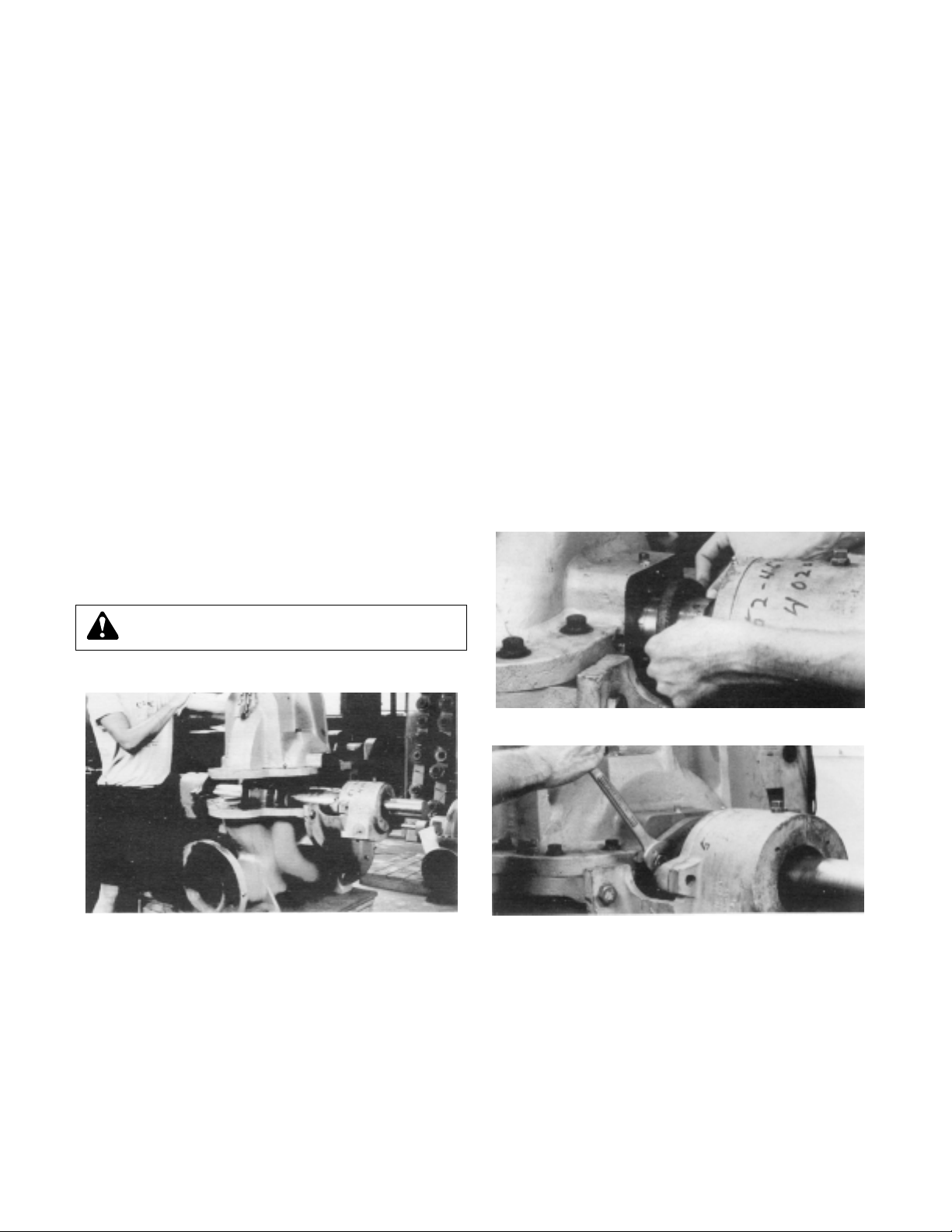
If lifting base pump is required, use a nylon string, chain, or
wire rope, hitch around both bearing supports. If lifting of the
entire pump is required, do so with slings placed under the
base rails as shown.
Care must be taken to size equipment for unbalanced loads
which may exist if the motor is not mounted on the base at the
time of lifting. Motor may or may not be mounted at the factory.
Pump, base, and driver assemblies where the base length
exceeds 100 inches may not be safe to lift as a complete
assembly. Damage to the baseplate may occur. If the driver has
been mounted on the baseplate at the factory, it is safe to lift
the entire assembly. If the driver has not been mounted at the
factory and the overall baseplate length exceeds 100 inches,
do not lift the entire assembly consisting of a pump, base, and
driver. Instead, lift the pump and baseplate to its final location
without the driver. Then mount the driver.
The best pump location for sound and vibration absorption is
on a concrete floor with subsoil underneath. If the pump location is overhead, special precautions should be undertaken to
reduce possible sound transmission. Consult a sound specialist.
If the pump is not on a closed system, it should be placed as
near as possible to the source of the liquid supply, and located
to permit installation with the fewest number of bends or
elbows in the suction pipe.
The installation must be evaluated to determine that the Net
Positive Suction Head Available (NPSHA) meets or exceeds the
Net Positive Suction Head Required (NPSHR), as stated by the
pump performance curve. See page 9 for more details on
proper suction piping installation.
4
ADDITIONAL SAFETY REQUIREMENTS:
ELECTRICAL SAFETY:
THERMAL SAFETY:
MECHANICAL SAFETY:
WARNING: Electrical Shock Hazard
Electrical connections to be made by a qualified
electrician in accordance with all applicable codes, ordinances, and good practices. Failure to follow these
instructions could result in serious personal injury or death,
or property damage.
WARNING: Electrical Overload Hazard
Three phase motors must have properly sized
heaters to provide overload and undervoltage protection.
Single phase motors have built-in overload protectors.
Failure to follow these instructions could result in serious
personal injury or death, or property damage.
WARNING: Extreme Temperature Hazard
If pump, motor, or piping are operating at extremely
high or low temperatures, guarding or insulation is required. Failure to follow these instructions could result in
serious personal injury or death, or property damage.
WARNING: Unexpected Startup Hazard
Disconnect and lockout power before servicing.
Failure to follow these instructions could result in serious
personal injury or death, or property damage.
WARNING: Excessive System Pressure Hazard
The maximum working pressure of the pump is listed
on the nameplate, do not exceed this pressure. Do not use
air to hydrotest pump. Failure to follow these instructions
could result in serious personal injury or death, or property
damage.
WARNING: Excessive Pressure Hazard
Volumetric Expansion
The heating of water and other fluids causes volumetric
expansion. The associated forces may cause failure of system components and release of high temperature fluids.
This will be prevented by installing properly sized and
located compression tanks and pressure relief valves.
Failure to follow these instructions could result in serious
personal injury or death, or property damage.
WARNING: Falling Objects Hazard
Eyebolts or lifting lugs, if provided, are for lifting only
the components to which they are attached. Failure to
follow these instructions could result in serious personal
injury or death, or property damage.
FIGURE 3
NYLON SLING,
CHAIN OR
WIRE ROPE
CHOKER
HITCH
AROUND
BEARING
FRAME
Page 5

5
INTRODUCTION
1. Purpose of Manual
This manual is furnished to acquaint you with some of the
practical ways to install, operate, and maintain this pump.
Read it completely before doing any work on your unit and
keep it handy for future reference.
Equipment cannot operate well without proper care. To keep
this unit at top efficiency, follow the recommended installation
and servicing procedures outlined in this manual.
2. Warranty
Refer to your local representative for warranty coverage.
3. Pump Identification
All pumps are designated by Serial Number, Model Number,
and Size. This information is stamped on an identification
plate which is mounted on the pump.
4. Installation
5. Receiving Pump
Check pump for shortages and damage immediately upon
arrival. (An absolute must.) Prompt reporting to the carrier’s
agent with notations made on the freight bill, will expedite
satisfactory adjustment by the carrier.
Pumps and drivers normally are shipped from the factory
mounted and painted with primer and one finish coat.
Couplings may be either completely assembled or have the
coupling hubs mounted on the shafts and the connecting
members removed. When the connecting members are
removed, they will be packaged in a separate container and
shipped with the pump or attached to the base plate.
Shafts are in alignment when the unit is shipped; however, due
to shipping, the pumps may arrive misaligned and, therefore,
alignment must be established during installation. Bell &
Gossett has determined that proper and correct alignment can
only be made by accepted erection practices. Refer to the following paragraphs on “Foundation,” “Base Plate Setting,”
“Grouting Procedure,” “Alignment Procedure” and “Doweling.”
6. Temporary Storage
If the pump is not to be installed and operated soon after
arrival, store it in a clean, dry place having slow, moderate
changes in ambient temperature. Rotate the shaft periodically
to coat the bearings with lubricant and to retard oxidation,
corrosion, and to reduce the possibility of false brinelling of
the bearings.
7. Location
The pump should be installed as near the suction supply as
possible, but no less than five suction diameters (refer to page
9, suction and discharge piping section) with the shortest and
most direct suction pipe practical. The total dynamic suction
lift (static lift plus friction losses in suction line) should not
exceed the limits for which the pump was sold.
The pump must be primed before starting. Whenever possible,
the pump should be located below the fluid level to facilitate
priming and assure a steady flow of liquid. This condition provides a positive suction head on the pump. It is also possible
to prime the pump by pressurizing the suction vessel.
When installing the pump, consider its location in relation to
the system to assure that sufficient Net Positive Suction Head
(NPSH) at pump suction is provided. Available NPSH must
always equal or exceed the required NPSH of the pump.
The pump should be installed with sufficient accessibility for
inspection and maintenance. A clear space with ample head
room should be allowed for the use of an overhead crane or
hoist sufficiently strong to lift the unit.
NOTE: Allow sufficient space to be able to dismantle pump
without disturbing the pump inlet and discharge piping.
Select a dry place above the floor level wherever possible.
Take care to prevent pump from freezing during cold weather
when not in operation. Should the possibility of freezing exist
during a shut-down period, the pump should be completely
drained, and all passages and pockets where liquid might collect should be blown out with compressed air.
Make sure there is a suitable power source available for the
pump driver. If motor driven, electrical characteristics should
be identical to those shown on motor data plate.
8. Foundation
A substantial foundation and footing should be built to suit
local conditions. The foundation must be substantial enough
to absorb vibration. (Hydraulic Institute Standards recommends the foundation weigh at least five (5) times the weight
of the pump unit.) It must form a permanent and rigid support
for the baseplate. This is important in maintaining the alignment of the coupled unit.
General HSCS Instructions
IMPORTANT
Do not install and operate Bell & Gossett Pumps, 3D Valves,
Suction Diffusers, etc., in closed systems unless the system
is constructed with properly sized safety devices and control devices. Such devices include the use of properly sized
and located pressure relief valves, compression tanks, pressure controls, temperature controls, and flow controls as
appropriate. If the system does not include these devices,
consult the responsible engineer or architect before making
pumps operational.
COMPRESSION TANK
SHOULD BE LOCATED
ON THE SUCTION SIDE
OF THE PUMP
B&G REDUCING
VALVE
COLD
WATER
SUPPLY
FROM BOILER
CHILLER OR CONVERTER
B&G ROLAIRTROL
AIR SEPARATOR
SUPPLY
TO SYSTEM
ISOLATION
VALVE
B&G CIRCUIT
SETTER
B&G TRIPLE DUTY
VALVE
B&G
SUCTION
DIFFUSER
Page 6

The foundation should be poured without interruption to within
1
/2 to 11/2 inches of the finished height. The top surface of the
foundation should be well scored and grooved before the
concrete sets; this provides a bonding surface for the grout.
Foundation bolts should be set in concrete as shown in Figure
4. An optional 4-inch long tube around the bolts at the top of
the concrete will allow some flexibility in bolt alignment to
match the holes in the base plate. Allow enough bolt length for
grout, shims, lower base plate flange, nuts and washers. The
foundation should be allowed to cure for several days before
the base plate is shimmed and grouted.
9. Base Plate Setting (Before Piping)
NOTE: This procedure assumes that a concrete foundation
has been prepared with anchor or hold down bolts extending
up ready to receive unit. It must be understood that pump and
motor have been mounted and rough aligned at the factory. If
motor is to be field mounted, consult factory for recommendations. Bell & Gossett cannot assume responsibility for final
alignment.
a. Use blocks and shims under base for support at anchor
bolts and midway between bolts, to position base
approximately 1" above the concrete foundation, with studs
extending through holes in the base plate.
b. By adding or removing shims under the base, level and
plumb the pump shaft and flanges. The base plate does not
have to be level.
c. Draw anchor nuts tight against base, and observe pump
and motor shafts or coupling hubs for alignment. (Temporarily remove coupling guard for checking alignment.)
d. If alignment needs improvement, add shims or wedges at
appropriate positions under base, so that retightening of
anchor nuts will shift shafts into closer alignment. Repeat
this procedure until a reasonable alignment is reached.
NOTE: Reasonable alignment is defined as that which is
mutually agree upon by pump contractor and the accepting
facility (final operator). Final alignment procedures are covered under “Alignment Procedures.”
e. Check to make sure the piping can be aligned to the pump
flanges without placing pipe strain on either flange.
f. Grout in base plate completely (See “Grouting Procedure”)
and allow grout to dry thoroughly before attaching piping to
pump. (24 hours is sufficient time with approved grouting
procedure.)
10. Grouting Procedure
Grout compensates for uneven foundation, distributes weight
of unit, and prevents shifting. Use an approved, non-shrinking
grout, after setting and leveling unit (See Figure 5).
a. Build strong form around the foundation to contain grout.
b. Soak top of concrete foundation thoroughly, then remove
surface water.
c. Base plate should be completely filled with grout.
d. After the grout has thoroughly hardened, check the founda-
tion bolts and tighten if necessary.
e. Check the alignment after the foundation bolts are
tightened.
f. Approximately 14 days after the grout has been poured or
when the grout has thoroughly dried, apply an oil base paint
to the exposed edges of the grout to prevent air and mois-
ture from coming in contact with the grout.
11. See ANSI/OSHA Coupler Guard Removal/Installation
(next page)
12. Alignment Procedure
NOTE:
Permissible misalignment will vary with the make of
coupling. Consult coupling manufacturer’s data when in
doubt.
Allowances are to be made for thermal expansion during cold
alignment, so that the coupling will be aligned at operating
temperature. In all cases, a coupling must be in alignment for
continuous operation. Even though the coupling may be lubricated, misalignment causes excessive wear, vibration, and
bearing loads that result in premature bearing failure and
ultimate seizing of the pump. Misalignment can be angular,
parallel, or a combination of these, and in the horizontal and
vertical planes. Final alignment should be made by moving
and shimming the motor on the base plate, until the coupling
hubs are within the recommended tolerances measured in
total run-out. All measurements should be taken with the
pump and motor foot bolts tightened. The shaft of sleeve
bearing motors should be in the center of its mechanical float.
NOTE: Proper alignment is essential for correct pump opera-
tion. This should be performed after base plate has been
properly set and grout has dried thoroughly according to
instructions. Final alignment should be made by shimming
driver only. Alignment should be made at operating
temperatures.
FIGURE 4 – FOUNDATION
FIGURE 5 – SETTING BASE PLATE AND GROUTING
WARNING: Unexpected Start-up Hazard
Disconnect and lock out power before servicing.
Failure to follow these instructions could result in serious
personal injury or death and property damage.
PIPE
SLEEVE
FOUNDATION
BOLT
BUILT-UP
CONCRETE FOUNDATION
GROUT ONLY TO
TOP OF BASE RAIL.
PUMP
BASE RAIL
APPROX.
1" GAP
CONCRETE
FOUNDATION
LEVELING OF PUMP BASE
ON CONCRETE FOUNDATION.
GROUT
WASHER
ALLOW 1" FOR SHIMS.
PLACE ON BOTH SIDES
OF ANCHOR BOLTS.
NOTE:
TO KEEP SHIMS IN
PLACE ALLOW GROUT
TO FLOW AROUND
HOLD DOWN LUGS.
(OPTIONAL)
6
Page 7

7
11. ANSI/OSHA COUPLER GUARD
REMOVAL/INSTALLATION
NOTE: Do not spread the inner and outer guards more than
necessary for guard removal or installation. Over spreading the
guards may alter their fit and appearance.
Removal
a. Remove the two capscrews that hold the outer (motor side)
coupler guard to the support bracket(s).
b. Spread the outer guard and pull it off the inner guard.
c. Remove the capscrew that holds the inner guard to the
support bracket.
d. Spread the inner guard and pull it over the coupler.
Installation
a. Check coupler alignment before proceeding. Correct if
necessary.
b. Spread the inner guard and place it over the coupler.
c. With the inner guard straddling the support bracket, install a
capscrew through the hole (or slot) in the support bracket
and guard located closest to the pump. Do not tighten the
capscrew.
d. Spread the outer guard and place it over the inner guard.
e. Install the outer guard capscrews by following the step
stated below which pertains to your particular pump:
i.
For pumps with a motor saddle support bracket: Ensure
the outer guard is straddling the support arm, and install
but do not tighten the two remaining capscrews.
ii.
For pumps without a motor saddle support bracket:
Insert the spacer washer between the holes located
closest to the motor in the outer guard, and install, but
do not tighten, the two remaining capscrews.
f. Position the outer guard so it is centered around the shaft,
and so there is less than a 1/4" of the motor shaft exposed.
On guards that utilize a slotted support bracket, the inner
guard will have to be positioned so there is only a 1/4" of
the pump shaft exposed.
g. Holding the guard in this position, tighten the three
capscrews.
WARNING: Unexpected Start-up Hazard
Disconnect and lock out power before servicing.
Failure to follow these instructions could result in serious
personal injury or death and property damage.
INNER GUARD
ATTACH SUPPORT BRACKET
TO BEARING HOUSING
THIS OPTION USED IN PLACE OF SPACER WHERE
OVERALL LENGTH OF GUARD EXCEEDS 12 INCHES
OR GUARD WIDTH IS OVER 10 INCHES ACROSS
THE FLATS.
OUTER GUARD
NUT
LOCKWASHER
LOCATE SUPPORT ARM
BETWEEN OUTER GUARD ENDS.
ALIGN THE ARM WITH HOLES IN
THE OUTER GUARD AND HOLES IN
THE SADDLE BRACKET.
BRACKET SUPPORT
CAPSCREW
FLAT WASHER
BRACKET SUPPORT
ATTACHES INSIDE HERE
IN LINE WITH BOLT
MOTOR SADDLE BRACKET
ATTACH TO MOTOR SADDLE
SPACER WASHER
SUPPORT BRACKET
ANSI/OSHA Coupling Guard Exploded View
for Typical Series HSCS Pump Installation
Page 8

8
Method 1 – Using Straight Edge & Taper Gauges
or Feelers
(See Figure 6A)
Proceed with this method only if satisfied that face and outside diameters of the coupling halves are square and concentric with the coupling borers. If this condition does not exist or
elastomeric couplings do not make this method convenient,
use Method 2.
1. Check angular misalignment using a micrometer or caliper.
Measure from the outside of one flange to the outside of
the opposite flange at four points 90° apart. DO NOT
ROTATE COUPLER. Misalignment up to
1
/64" per inch of
coupler radius is permissible.
2. At four points 90° apart (DO NOT ROTATE COUPLER),
measure the parallel coupler misalignment by laying a
straight edge across one coupler half and measuring the
gap between the straight edge and opposite coupler half.
Up to a
1
/64" gap is permissible.
Method 2 – Using Dial Indicators (Figure 6B)
a. Make sure each hub is secured to its respective shaft and
that all connecting and/or spacing elements are removed at
this time.
b. The gap between the coupling hubs is set by the manufac-
turer before the units are shipped. However, this dimension
should be checked. (Refer to the coupling manufacturer’s
specifications supplied with the unit.)
c. Scribe index lines on coupling halves as shown in Figure
6B.
d. Mount dial indicator on one hub as shown for parallel align-
ment. Set dial to zero.
e. Turn both coupling halves so that index lines remain
matched. Observe dial reading to see whether driver needs
adjustment (See paragraph i below).
f. Mount dial indicator on one hub as shown for angular align-
ment. Set dial to zero.
g. Turn both coupling halves so that index lines remain
matched. Observe dial reading to see whether driver needs
adjustment (See paragraph i below).
h. Assemble coupling. Tighten all bolts and set screw(s). It
may be necessary to repeat steps c through f for a final
check.
i. For single element couplings, a satisfactory parallel mis-
alignment is .004"T.I.R., while a satisfactory angular misalignment is .004"T.I.R. per inch of radius R (See Figure 6B).
Final Alignment
Final alignment cannot be accomplished until the pump has
been operated initially for a sufficient length of time to attain
operating temperature. When normal operating temperature
has been attained, secure the pump to re-check alignment
and compensate for temperature accordingly. See Alignment
Section.
OPTIONAL Alignment Procedure
If desired, the pump and motor feet can be doweled to the
base after final alignment is complete. This should not be
done until the unit has been run for a sufficient length of time
and alignment is within the tolerance. See Doweling Section.
NOTE: Pump may have been doweled to base at factory.
FIGURE 6A – CHECKING ALIGNMENT (METHOD 1)
FIGURE 6B – CHECKING ALIGNMENT (METHOD 2)
WARNING: Rotating Components Hazard
Do not operate pump without all guards in place.
Failure to follow these instructions could result in serious
personal injury or death and property damage.
CAUTION: Extreme Temperature and/or
Flying Debris Hazard
Eye protection and gloves required. Failure to follow these
instructions could result in property damage and/or moderate personal injury.
STRAIGHT EDGE
FEELER GAGE
ANGULAR ALIGNMENT PARALLEL ALIGNMENT
INCORRECT ALIGNMENT
STRAIGHT EDGE
FEELER GAGE
CORRECT ALIGNMENT
PARALLEL
ALIGNMENT
DIAL
INDICATOR
INDEX LINE
R
RESILIENT
SEPARATOR
ANGULAR
ALIGNMENT
DIAL
INDICATOR
Page 9

9
Page 10

13. DOWELING
Dowel the pump and driving unit as follows:
a. Drill holes through diagonally opposite feet and into the
base. Holes must be of a diameter
1
/64 inch less than the
diameter of the dowel pins. Clean out the chips.
b. Ream the holes in feet and base to the proper diameter for
the pins (light push fit). Clean out the chips.
c. Insert pins to be approximately flush with feet.
14. SUCTION AND DISCHARGE PIPING
General
When installing the pump piping, be sure to observe the fol-
lowing precautions:
Piping should always be run to the pump.
Do not move pump to pipe. This could make final alignment
impossible.
Both the suction and discharge piping should be supported
independently near the pump and properly aligned, so that no
strain is transmitted to the pump when the flange bolts are
tightened. Use pipe hangers or other supports at necessary
intervals to provide support. When expansion joints are used
in the piping system, they must be installed beyond the piping
supports closest to the pump. Tie bolts should be used with
expansion joints to prevent pipe strain. Do not install expansion joints next to the pump or in any way that would cause a
strain on the pump resulting from system pressure changes. It
is usually advisable to increase the size of both suction and
discharge pipes at the pump connections to decrease the loss
of head from friction.
Install piping as straight as possible, avoiding unnecessary
bends. Where necessary, use 45-degree or long sweep
90-degree fitting to decrease friction losses.
Make sure that all piping joints are air-tight.
Where flanged joints are used, assure that inside diameters
match properly.
Remove burrs and sharp edges when making up joints.
Do not “spring” piping when making any connections.
Provide for pipe expansion when hot fluids are to be pumped.
Suction Piping
When installing the suction piping, observe the following
precautions (See Figure 7).
The sizing and installation of the suction piping is extremely
important. It must be selected and installed so that pressure
losses are minimized and sufficient liquid will flow into the
pump when started and operated. Many NPSH (Net Positive
Suction Head) problems can be attributed directly to improper
suction piping systems.
Friction losses caused by undersized suction piping can
increase the fluid’s velocity into the pump. As recommended
by the Hydraulic Institute Standard ANSI/HI 1.1-1.5-1994, suction pipe velocity should not exceed the velocity in the pump
suction nozzle. In some situations pipe velocity may need to
be further reduced to satisfy pump NPSH requirements and to
control suction line losses. Pipe friction can be reduced by
using pipes that are one to two sizes larger than the pump
suction nozzle in order to maintain pipe velocities less than
5 feet/second.
FIGURE 7 – SUCTION PIPE INSTALLATIONS
(Piping Supports Not Shown)
CHECK VALVE
GATE VALVE
INCREASER
CORRECT
C OF PIPE
SUCTION PIPE INSTALLED WITH
A GRADUAL RISE TO PUMP
L
LEVEL
AIR POCKET
INCORRECT
AIR POCKET
INCORRECT
AIR POCKET
INCORRECT
GRADUAL RISE
TO PUMP
NO AIR
POCKETS
CORRECT
NO AIR
POCKETS
GRADUAL RISE
TO PUMP
ECCENTRIC
REDUCER
CORRECT
DISTANCE PLUS
ECCENTRIC REDUCER
STRAIGHTENS FLOW
CORRECT
PATH OF
WATER
INCORRECT
1ä
Page 11

Suction piping should be short in length, as direct as possible,
Ê
and never smaller in diameter than the pump suction opening.
Ê
If the suction pipe is short, the pipe diameter can be the same
Ê
size as the suction opening. If longer suction pipe is r
equired,
Ê
pipes should be one or two sizes larger than the opening
Ê
depending on piping length.
Ê
Suction piping for horizontal double suction pumps should not
Ê
be installed with an elbow close to the suction flange of the
Ê
pump except when the suction elbow is in the vertical plane.
Ê
A suction pipe of the same size as the suction nozzle
Ê
approaching at any angle other than straight up or straight
Ê
down must have the elbow located 10 pipe diameters from the
Ê
suction flange of the pump. Vertical mounted pumps and other
Ê
space limitations require special piping.
Ê
There is always an uneven turbulent flow around an elbow and
Ê
when it is in a position other than the vertical it causes more
Ê
liquid to enter one side of the impeller than the other (See
Ê
Figure 8). This results in high unequalized thrust loads that will
Ê
overheat the bearings and cause rapid wear in addition to
Ê
affecting hydraulic performance.
Ê
When operating on a suction lift, the suction pipe should slope
Ê
upward to the pump nozzle. A horizontal suction line must
Ê
have a gradual rise to the pump. Any high point in the pipe will
Ê
become filled with air and thus prevent proper operation on
Ê
the pump. When reducing the piping to the suction opening
Ê
diameter use an eccentric reducer with the eccentric side
Ê
down to avoid air pockets.
Ê
NOTE: When operating on suction lift never use a straight
Ê
taper reducer in a horizontal suction line, as it tends to form an
Ê
air pocket in the top of the reducer and the pipe.
Ê
To facilitate cleaning pump liquid passage without dismantling
Ê
pump, a short section of pipe (Dutchman or spool piece) so
Ê
designed that it can be readily dropped out of the line can be
Ê
installed adjacent to the suction flange. With this arrangement,
Ê
any matter clogging the impeller is accessible by removing the
Ê
nozzle (or pipe section).
Ê
Valves in Suction Piping
When installing valves in the suction piping, observe the fol-
lowing precautions:
a. If the pump is operating under static suction lift conditions,
a foot valve may be installed in the suction line to avoid the
necessity of priming each time the pump is started. This
valve should be of the flapper type, rather than the multiple
spring type, sized to avoid excessive friction in the suction
line. (Under all other conditions, a check valve, if used,
should be installed in the discharge line.) (See “Valves in
Discharge Piping” below)
b. When foot valves are used, or where there are other possi-
bilities of “water hammer,” close the discharge valve slowly
before shutting down the pump.
c. Where two or more pumps are connected to the same
suction line, install gate valves so that any pump can be
isolated from the line. Gate valves should be installed on
the suction side of all pumps with a positive pressure for
maintenance purposes. Install gate valves with stems horizontal to avoid air pockets. Globe valves should not be
used, particularly where NPSH is critical.
d. The pump must never be throttled by the use of a valve on
the suction side of the pump. Suction valves should be
used only to isolate the pump or maintenance purposes,
and should always be installed in positions to avoid air
pockets.
e. A pump drain valve should be installed in the suction piping
between the isolation valve and the pump.
Discharge Piping
If the discharge piping is short, the pipe diameter can be the
same as the discharge opening. If the piping is long, pipe
diameter should be one or two sizes larger than the discharge
opening. On long horizontal runs, it is desirable to maintain as
even a grade as possible. Avoid high spots, such as loops,
which will collect air and throttle the system or lead to erratic
pumping.
Valves in Discharge Piping
A triple duty valve should be installed in the discharge. The
triple duty valve placed on the pump protects the pump from
excessive back pressure, and prevents liquid from running
back through the pump in case of power failure.
Pressure Gauges
Properly sized pressure gauges should be installed in both the
suction and discharge nozzles in the gauge taps (which are
provided on request). The gauges will enable the operator to
easily observe the operation of the pump, and also determine
if the pump is operating in conformance with the performance
curve., If cavitation, vapor binding, or other unstable operation
should occur, widely fluctuating discharge pressure will be
noted.
Pump Insulation
On chilled water applications most pumps are insulated. As
part of this practice, the pump bearing housings should not
be
insulated since this would tend to “trap” heat inside the housing. This could lead to increased bearing temperatures and
premature bearing failures.
FIGURE 8 – UNBALANCED LOADING OF A DOUBLE SUCTION
IMPELLER DUE TO UNEVEN FLOW AROUND ON
ELBOW ADJACENT TO THE PUMP.
PUMP CASING
PUMP SUCTION
FLANGE
CASING RINGS
IMPELLER
WATER PRESSURE
INCREASES HERE CAUSING
A GREATER FLOW TO ONE
SIDE OF THE IMPELLER
SUCTION
ELBOW
1£
Page 12
OPERATION
1. Pre-start Checks
Before initial start of the pump, make the following
inspections:
a. Check alignment between pump and motor.
b. Check all connections to motor and starting device with
wiring diagram. Check voltage, phase, and frequency on
motor nameplate with line circuit.
c. Check suction and discharge piping and pressure gauges
for proper operation.
d. Check impeller adjustment, see specific section for proper
adjustment.
e. Turn rotating element by hand to assure that it rotates
freely.
f. Check driver lubrication.
g. Assure that pump bearings are properly lubricated.
h. Assure that coupling is properly lubricated, if required.
i. Assure that pump is full of liquid (See 2. Priming) and all
valves are properly set and operational, with the discharge
valve closed, and the suction valve open.
j. Check rotation. Be sure that the drive operates in the direc-
tion indicated by the arrow on the pump casing as serious
damage can result if the pump is operated with incorrect
rotation. Check rotation each time the motor leads have
been disconnected.
2. Priming
If the pump is installed with a positive head on the suction, it
can be primed by opening the suction and vent valve and
allowing the liquid to enter the casing.
If the pump is installed with a suction lift, priming must be
done by other methods such as foot valves, ejectors, or by
manually filling the casing and suction line.
3. Starting
a. Close drain valves and valve in discharge line.
b. Open fully all valves in the suction line.
c. Prime the pump.
NOTE: If the pump does not prime properly, or loses prime
during start-up, it should be shutdown and the condition
corrected before the procedure is repeated.
d. When the pump is operating at full speed, open the dis-
charge valve slowly. This should be done promptly after
start-up to prevent damage to pump by operating at zero
flow.
4. Operating Checks
a. Check the pump and piping to assure that there are no
leaks.
b. Check and record pressure gauge readings for future
reference.
c. Check and record voltage, amperage per phase, and kw if
an indicating wattmeter is available.
d. Check bearings for lubrication and temperature. Normal
temperature is 180° maximum.
e. Make all pump output adjustments with the discharge line.
5. Freezing Protection
Pumps that are shut down during freezing conditions should
be protected by one of the following methods.
a. Drain the pump; remove all liquids from the casing.
b. Keep fluid moving in the pump and insulate or heat the
pump to prevent freezing.
WARNING: Rotating Components Hazard
Do not operate pump without all guards in place.
Failure to follow these instructions could result in serious
personal injury or death and property damage.
WARNING: Rotating Components Hazard
Do not operate pump without all guards in place.
Failure to follow these instructions could result in serious
personal injury or death and property damage.
CAUTION: Cavitation Damage Hazard
Do not throttle the suction line to adjust the pump
output. Failure to follow these instructions could result in
property damage and/or moderate personal injury.
CAUTION: Bearing/Seal Damage Hazard
Do not let heated pump temperature rise above
150°F. Failure to follow these instructions could result in
property damage and/or moderate personal injury.
CAUTION: Seal Damage Hazard
Do not run pump dry, seal damage may occur.
Failure to follow these instructions could result in property
damage and/or moderate personal injury.
WARNING: Unexpected Startup Hazard
Disconnect and lockout power before servicing.
Failure to follow these instructions could result in serious
personal injury or death or property damage.
WARNING: Electric Shock Hazard
Electrical connections to be made by a qualified
electrician in accordance with all applicable codes, ordinances and good practices. Failure to follow these instructions could result in serious personal injury, death, or property damage.
1Ó
Page 13
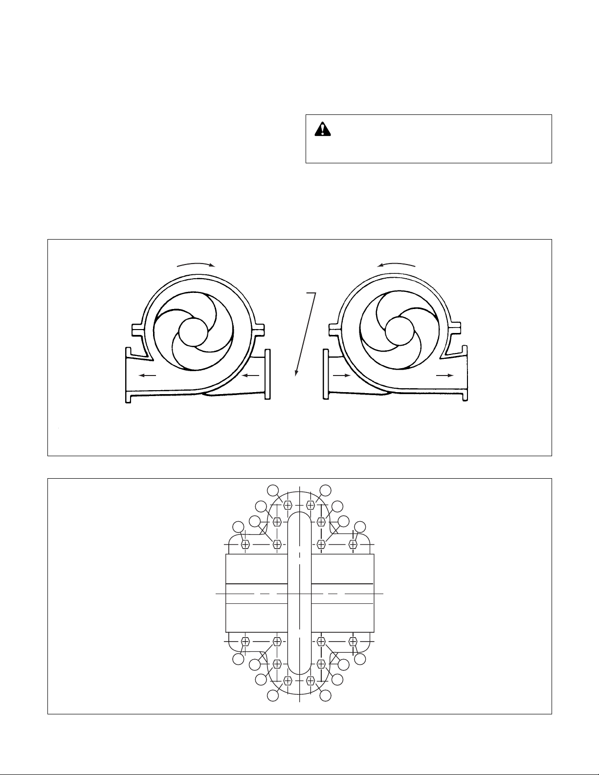
CHANGING ROTATION
Series HSCS centrifugal pumps can be operated left hand or
right hand when viewed from the pump end of the pump. If
you wish to reverse the suction and discharge nozzles, this
can be accomplished with the same pump as follows:
IMPORTANT: Refer to the disassembly and assembly proce-
dures section of this manual for proper disassembly and
assembly techniques:
1. Remove the impeller from the shaft, turn it 180° and replace
it on the shaft. (Follow the disassembly procedures given in
this manual.)
2.With the rotating element out of the casing, remove the
casing from the bedplate and turn 180°.
3. Set the rotating element back in the casing and reassemble
the pump.
NOTE: The impeller and casing are in the same relationship
to each other as they were originally. The shaft and motor
are also in the same relationship to each other as they were
originally.
4. Reassemble pump and realign the coupling as called for in
the alignment instructions.
5. The rotation of the motor must be changed by switching the
motor leads.
NOTE: Unless the motor rotation is reversed, the impeller
will run backward.
WARNING: Rotating Components Hazard
Do not operate pump without all guards in place.
Failure to follow these instructions could result in serious
personal injury or death and property damage.
ROTATION ROTATION
DISCHARGE DISCHARGE
SUCTION
CLOCKWISE ROTATION VIEWED
FROM THE COUPLING END
COUNTER-CLOCKWISE ROTATION VIEWED
FROM THE COUPLING END
FIGURE 9 – CORRECT RELATIONSHIP OF IMPELLER AND CASING
13
5
1
9
15
7
3
11
16
8
4
12
14
6
2
10
FIGURE 10 – MAIN JOINT BOLTS
1Î
Page 14

TROUBLE SHOOTING
Between regular maintenance inspections, be alert for signs of
motor or pump trouble. Common symptoms are listed below.
Correct any trouble immediately and AVOID COSTLY REPAIR
AND SHUTDOWN.
No Liquid Delivered
CAUSES CURES
1. Lack of prime. Fill pump and suction pipe completely with liquid.
2. Loss of prime. Check for leaks in suction pipe joints and fittings; vent casing to remove
accumulated air.
3. Suction lift too high. If no obstruction at inlet, check for pipe friction losses. However, static
lift may be too great. Measure with mercury column or vacuum gauge
while pump operates. If static lift is too high, liquid to be pumped must
be raised or pump lowered.
4. Discharge head too high. Check pipe friction losses. Large piping may correct condition. Check
that valves are wide open.
5. Speed too low. Check whether motor is directly across-the-line and receiving full voltage. Or frequency may be too low; motor may have an open phase.
6. Wrong direction of rotation. Check motor rotation with directional arrow on pump casing.
7. Impeller completely plugged. Dismantle pump and clean impeller.
Not Enough Liquid Delivered
8. Air leaks in suction piping. If liquid pumped is water or other non-explosive, and explosive gas or
dust is not present, test flanges for leakage with flame or match, or by
plugging inlet and putting line under pressure. A gauge will indicate a
leak with a drop of pressure.
9. Speed too low. See item 5.
10. Discharge head too high. See item 4.
11. Suction lift too high. See item 3.
12. Impeller partially plugged. See item 7.
13. Cavitation; insufficient NPSH a. Increase positive suction head on pump by lowering pump.
(depending on installation)
b. Sub-cool suction piping at inlet to lower entering liquid temperature.
c. Pressurization suction vessel.
14. Defective impeller. Inspect impeller, bearings and shaft. Replace if damaged or vane sec-
tions badly eroded.
15. Foot valve too small or partially Area through ports of valve should be at least as large as area of suction
obstructed. pipe – preferably 1
1
/2 times. If strainer is used, net clear area should be
3 to 4 times area of suction pipe.
16. Suction inlet not immersed If inlet cannot be lowered, or if eddies through which air is sucked perdeep enough. sist when it is lowered, chain a board to suction pipe. It will be drawn
into eddies, smothering the vortex.
17. Wrong direction of rotation. Symptoms are an overloaded drive and about
1
/3 rated capacity from
pump. Compare rotation of motor with directional arrow on pump casing.
18. Too small impeller diameter. Check with factory to see if a larger impeller can be used; otherwise, cut
(Probable cause if none of above.) pipe losses or increase speed – or both, as needed. But be careful not
to seriously overload drive.
19. Speed too low. See item 5.
20. Air leaks in suction piping. See item 8.
1{
Page 15

Not Enough Pressure
CAUSES CURES
21. Mechanical defects. See item 14 and 15.
22. Obstruction in liquid passages. Dismantle pump and inspect passages of impeller and casing. Remove
obstruction.
23. Air or gases in liquid. (Test in May be possible to over rate pump to point where it will provide
laboratory, reducing pressure on adequate pressure despite condition. Better to provide gas separation
liquid to pressure in suction line. chamber on suction line near pump, and periodically exhaust accumuWatch for bubble formation.) lated gas. See item 13.
24. Too small impeller diameter. See item 18.
(Probable cause if none above.)
Pump Operates For Short Time, Then Stops
25. Incomplete priming. Free pump, piping and valves of all air. If high points in suction line pre-
vent this, they need correcting. See page 19.
26. Suction lift too high. See item 3.
27. Air leaks in suction piping. See item 8.
28. Air or gases in liquid. See item 23.
Pump Takes Too Much Power
29. Head lower than rating; thereby Machine impeller’s OD to size advised by factory.
pumping too much liquid.
30. Cavitation See item 13.
31. Mechanical defects. See items 14 and 15.
32. Suction inlet not immersed See item 16.
enough.
33. Liquid heavier (in either Use larger driver. Consult factory for recommended size. Test liquid for
viscosity or specific gravity) viscosity and specific gravity.
than allowed for.
34. Wrong direction of rotation. See item 6.
35. Casing distorted by excessive Check alignment. Examine pump for friction between impeller and
strains from suction or casing. Replace damaged parts.
discharge piping.
36. Shaft bent due to damage – Check deflection of rotor by turning on bearing journals. Total indicator
through shipment, operation, run-out should not exceed 0.002 on shaft and 0.004 inch on impeller
or overhaul. wearing surface.
37. Mechanical failure of critical Check bearings and impeller for damage. Any irregularity in these parts
pump parts. will cause a drag on shaft.
38. Misalignment. Realign pump and driver.
39. Speed may be too high Check voltage on motor.
(brake hp of pump varies as the
cube of the speed; therefore,
any increase in speed means
considerable increase in
power demand).
40. Electrical defects. The voltage and frequency of the electrical current may be lower than
that for which the motor was built; or there may be defects in motor. The
motor may not be ventilated properly due to a poor location.
41. Mechanical defects in turbine, If trouble cannot be located, consult factory.
engine or other type of drive
exclusive of motor.
1x
Page 16

MAINTENANCE
1. General Maintenance
Operating conditions vary so widely that to recommend one
schedule of preventative maintenance for all centrifugal
pumps is not possible. Yet some sort of regular inspection
must be planned and followed. We suggest a permanent
record be kept of the periodic inspections and maintenance
performed on your pump. This recognition of maintenance
procedure will keep your pump in good working condition, and
prevent costly breakdown.
One of the best rules to follow in the proper maintenance of
your centrifugal pump is to keep a record of actual operating
hours. Then, after a predetermined period of operation has
elapsed, the pump should be given a thorough inspection. The
length of this operating period will vary with different applications, and can only be determined from experience. New
equipment, however, should be examined after a relatively
short period of operation. The next inspection period can be
lengthened somewhat. This system can be followed until a
maximum period of operation is reached which should be considered the operating schedule between inspections.
2. Maintenance of Pump Due to Flood Damage
The servicing of centrifugal pumps after a flooded condition is
a comparatively simple matter under normal conditions.
Bearings are a primary concern on pumping units. First, dis-
mantle the bearings; clean and inspect them for any rusted or
badly worn surfaces. If bearings are free from rust and wear,
reassemble and relubricate them with one of the recommended pump lubricants. Depending on the length of time the
pump has remained in the flooded area, it is unlikely that bearing replacement is necessary; however, in the event that rust
or worn surfaces appear, it may be necessary to replace the
bearings.
Next, inspect the stuffing box, and clean out any foreign matter that might clog the box. Mechanical seals should be
cleaned and thoroughly flushed.
Couplings should be dismantled and thoroughly cleaned.
Any pump that is properly sealed at all joints and connected to
both the suction and discharge should exclude outside liquid.
Therefore, it should not be necessary to go beyond the bearings, stuffing box, and coupling when servicing the pump.
3. Bearing Lubrication – Grease
Grease lubricated ball bearings are packed with grease at the
factory and ordinarily will require no attention before starting,
provided the pump has been stored in a clean, dry place prior
to its first operation. The bearings should be watched the first
hour or so after the pump has been started to see that they
are operating properly.
The importance of proper lubrication cannot be over emphasized. It is difficult to say how often a bearing should be
greased, since that depends on the conditions of operation. It
is well to add one ounce of grease at regular intervals, but it is
equally important to avoid adding too much grease. For average operating conditions, it is recommended that 1 oz. of
grease be added at intervals of three to six months, and only
clean grease be used. It is always best if unit can be stopped
while grease is added to avoid overloading.
NOTE: Excess grease is the most common cause of
overheating.
A lithium based NLGI-2 grade grease should be used for lubri-
cating bearings where the ambient temperature is above
-20°F. Grease lubricated bearings are packed at the factory
with Shell Alvania No 2. Other recommended greases are
Texaco Multifak No. 2 and Mobilux No. 2 grease.
Greases made from animal or vegetable oils are not recommended due to the danger of deterioration and forming of
acid. Do not use graphite. Use of an ISO VG 100 mineral base
oil with rust and oxidation inhibitors is recommended.
The maximum desirable operating temperature for ball bearings is 180°F. Should the temperature of the bearing frame rise
above 180°F, the pump should be shut down to determine the
cause.
Bearing Lubrication – Oil
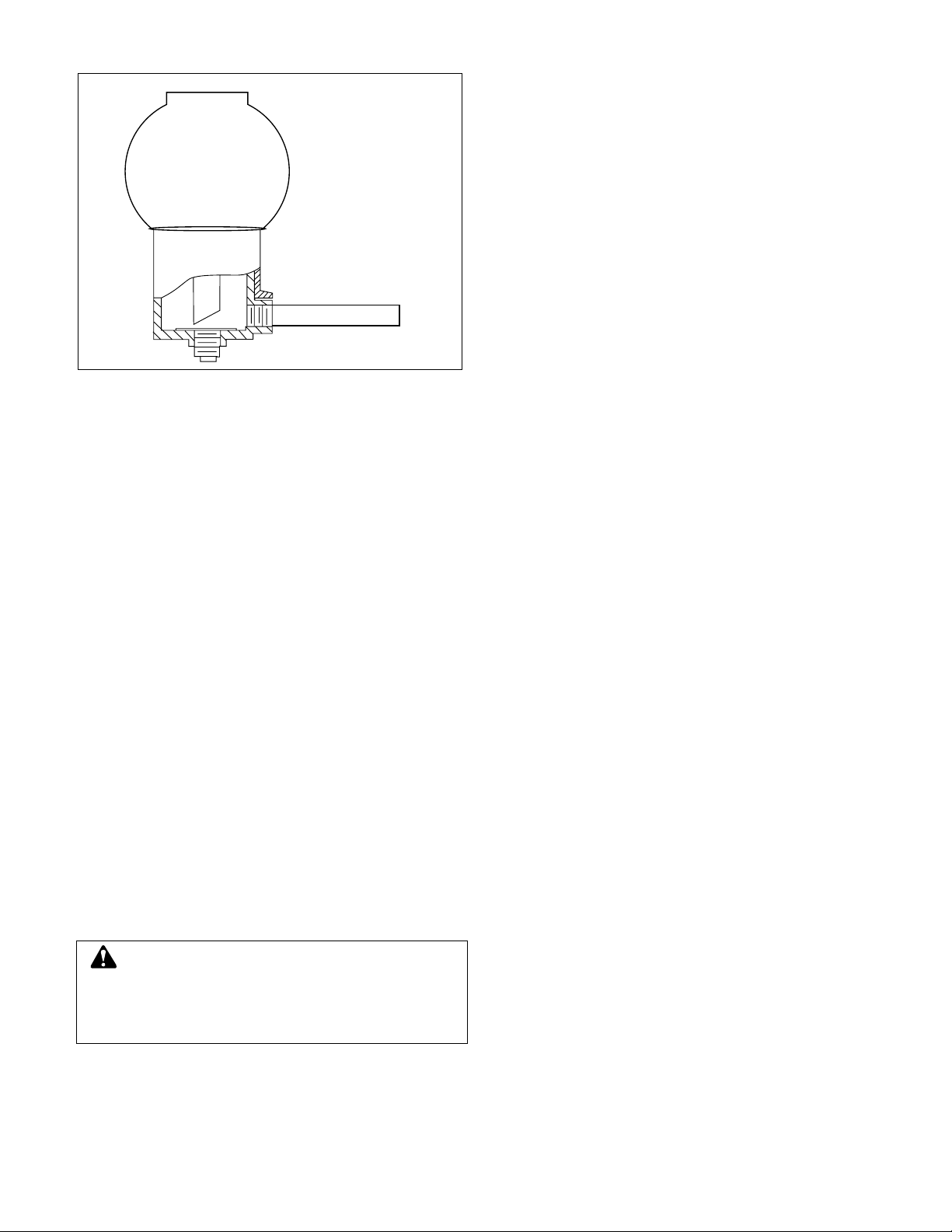
Oil lubrication on HSCS Series pumps is considered special.
Oil lubrication pumps are installed with Trico oilers (See Figure
11). The oilers keep the oil level in the housings constant.
After the pump has been installed, flush the housing to remove
dirt, grit, and other impurities that may have entered the
bearing housing during shipment or installation. Then refill the
housing with proper lubricant. (The housing must be filled
using the Trico oiler.) The oil level will be maintained by the
Trico oiler. (See the SERVICE section for proper instructions.)
1È
Page 17
4. Mechanical Seals
FIGURE 11 – TRICO OILER
A Mobile Oil, DTE Medium, or equal, meeting the following
specification will provide satisfactory lubrication. SImilar oils
can be furnished by all major oil companies. It is the responsibility of the oil vendor to supply a suitable lubricant.
Ê
(1) Saybolt viscosity at 100ºF . . . . . . . . . . 215 SSU-240 SSU
(2) Saybolt viscosity at 210ºF . . . . . . . . . . . . . . . . . . . 49SSU
(3) Viscosity index, minimum. . . . . . . . . . . . . . . . . . . . . . . . 95
(4) API gravity. . . . . . . . . . . . . . . . . . . . . . . . . . . . . . . . . 28-33
(5) Pour point, maximum . . . . . . . . . . . . . . . . . . . . . . . . +20ºF
(6) Flash point, minimum . . . . . . . . . . . . . . . . . . . . . . . . 400ºF
(7) Additives . . . . . . . . . . . . . . . . . Rust & Oxidation inhibitors
(8) ISO viscosity . . . . . . . . . . . . . . . . . . . . . . . . . . . . . . . . . 46
ent suppliers should not be mixed.
NOTE: Oils from dif
Engine oils are not recommended.
fer
Ê
The oil should be a non-foaming, well refined, good grade,
straight cut, filtered mineral oil. It must be free from water,
sediment, resin, soaps, acid and fillers of any kind.
Ê
In installations with moderate temperature changes, low
humidity, and a clean atmosphere, the oil should be changed
after approximately 1000 hours of operation. The oil should be
inspected at this stime to determine the operating period
before the next oil change. Oil change periods may be
increased up to 2000-4000 hours based on an 8000 hour year.
Check the oil frequently for moister, dirt, or signs of “breakdown,” especially during the fist 1000 hours.
Ê
a. Mechanical seals are precision products and should be
treated with care. Use special care when handling seals.
Clean parts are essential to prevent scratching the finely
lapped sealing faces. Even light scratches on these faces
could result in leaky seals.
Ê
b. Normally, mechanical seals require no adjustment or main-
tenance, except routine replacement of worn, or broken
Ê
parts.
c. A mechanical seal which has been used should not be put
back into service until sealing faces have been replaced or
relapped. (Relapping is generally economical only in seals
two inches in size and above.)
Ê
Four important rules which should always be followed for
optimum seal life are:
1. Keep the seal faces clean as possible.
2. Keep the seal as cool as possible.
Ê
Ê
Ê
3. Assure that the seal always has proper lubrication.
Ê
4. If seal is lubricated with filtered fluid, clean filter
Ê
Ê
frequently.
5. Packing Seal
Ê
When a pump with packing is first started it is advisable to
have the packing slightly loose without causing an air leak. As
Ê
the pump runs in, gradually tighten the gland bolts evenly
Ê
gland should never be drawn to the point wher
compressed too tightly and no leakage occurs. This will cause
Ê
the packing to burn, score the shaft sleeve and prevent liquid
Ê
from circulating through the stuffing box cooling the package.
Ê
NOTE: Eccentric run-out of the shaft or sleeve through the
packing could result in excessive leakage that cannot be com-
Ê
pensated for
Ê
sleeve replacement. Packing should be checked frequently
and replaced as service indicates. Six months might be a rea-
Ê
. Correction of this defect requires shaft and/or
e packing is
sonable expected life, depending on the operating conditions.
Ê
6. Cleaning Without Dismantling Pump
A short section of pipe so designed that it can be readily
Ê
dropped out of the line can be installed adjacent to the suction
Ê
flange. With this arrangement, any matter clogging the
impeller is accessible by r
Ê
If the pump cannot be freed of clogging after the above
Ê
methods have been tried, dismantle the unit as previously
Ê
described to locate the trouble.
emoving the pipe section.
Ê
Ê
Ê
Ê
Ê
Ê
. The
Ê
Ê
Ê
Ê
Ê
Ê
Ê
Ê
Ê
Ê
Ê
Ê
Ê
Ê
Ê
Ê
Ê
Ê
Ê
Ê
Ê
Ê
Ê
Ê
Ê
Ê
Ê
Ê
Ê
CAUTION:
Do not over oil; this causes the bearings to run hot.
The maximum desirable bearing housing operating
temperature for all ball bearings is 180º)F
. Should the
temperature of the bearing frame exceed 180º)F (measured
by thermometer) shut down pump to determine the cause.
Ê
Ê
Ê
Ê
Ê
Ê
1Ç
Page 18

EVERY MONTH Check bearing temperature with a thermometer, not by hand
. If bearings are running hot (over
Ê
180ºF), it may be the result of too much lubricant. If changing the lubricant does not correct the
Ê
condition, disassembly and inspect the bearing. Lip seals bearing on the shaft may also cause the
Ê
housing to run hot. Lubricate lip seals to correct.
Ê
EVERY 3 MONTHS Check the oil on oil lubricated units. Check grease lubricated bearings for saponification. This
Ê
condition is usually caused by the infiltration of water or other fluid passing the baring shaft
Ê
seals and can be noticed immediately upon inspection, since it gives the grease a whitish color.
Ê
Wash out the bearings with a clean industrial solvent and replace the grease with the proper type
Ê
as recommended.
Ê
EVERY 6 MONTHS Check the packing and replace if necessary. Use the grade recommended. Be sure the lantern rings
Ê
are centered in the stuffing box at the entrance of the stuffing box piping connection.
Ê
Take vibration readings on the bearing housings. Compare the readings with the last set of readings
Ê
to check for possible pump failure (e.g. bearings)
Ê
Check shaft or shaft sleeve for scoring. Scoring accelerates packing wear.
Ê
Check alignment of pump and motor. Shim up units if necessary. If misalignment reoccurs
Ê
frequently, inspect the entire piping system. Unbolt piping at suction and discharge flanges to see if
Ê
it springs away, thereby indicating strain on the casing. Inspect all piping supports for soundness
Ê
and effective support of load. Correct as necessary.
Ê
EVERY YEAR Remove the upper half of the casing. Inspect the pump thoroughly for wear, and order replacement
Ê
parts if necessary.
Ê
Check wear ring clearances. Replace when clearances become three (3) times their normal clear-
Ê
ance or when a significant decrease in discharge pressure for the same flow rate is observed. See
Ê
Engineering Data Section for standard clearances.
Ê
Remove any deposit or scaling. Clean out stuffing box piping.
Ê
Measure total dynamic suction and discharge head as a test of pump performance and pipe
Ê
condition. Record the figures and compare them with the figures of the last test. This is important,
Ê
especially where the fluid being pumped tends to form a deposit on internal surfaces. Inspect foot
Ê
valves and check valves, especially the check valve which safeguards against water hammer when
Ê
the pump stops. A faulty foot or check valve will reflect also in poor performance of the pump while
Ê
In operation.
NOTE: The above time table is based on the assumption that after start-up, the unit had been constantly monitored and
such a schedule was found to be consistent with operation, as shown by stable readings. Extreme or unusual applications or
conditions should be taken into consideration when establishing the maintenance intervals.
MAINTENANCE TIME TABLE
1n
Page 19

SERVICE INSTRUCTIONS
DISASSEMBLY AND REASSEMBLY PROCEDURES
The procedures outlined in this section cover the dismantling
and reassembly of two different types of Series HSCS pump
construction.
A. HSCS pump with packing
B. HSCS pump with mechanical seals.
Each procedure provides the step-by-step instructions for dismantling and then reassembling the pump, depending upon
the type of shaft seal used.
When working on the pump, use accepted mechanical practices to avoid unnecessary damage to parts. Check clearances and conditions of parts when pump is dismantled and
replace if necessary. Steps should usually be taken to restore
impeller and casing ring clearance when it exceeds three
times the original clearance.
If your pump has adjustable wear rings, please refer to the
instructions on page 26.
A. DISMANTLING (PUMP WITH PACKING)
WARNING:Electrical Shock Hazard
Electrical connections to be made by a qualified
electrician in accordance will all applicable codes, ordinances, and good practices. Failure to follow these
instructions could result in serious personal injury or death,
or property damage.
WARNING:Unexpected Startup Hazard
Disconnect and lockout power before servicing.
Failure to follow these instructions could result in serious
personal injury or death, or property damage.
LUBRICATION FOR PACKING
“A”
LUBRICATION FOR
MECHANICAL SEALS
WARNING: Prior to working on pump the power
source should be disconnected with lockout provisions so power cannot be re-energized to the motor. Close
isolating suction and discharge valves. Failure to follow
these instructions could result in property damage, severe
personal injury, or death.
TABLE “A”
Pump Size
Qty.
Dimension A
2-904-9
8x12x22M 26
13.50
8x12x22L 26
10x14x20S 26
12x16x23 26
15.81
14x16x17 24
14x18x23 32
10x14x20L 26 16.60
FIGURE 12 – ASSEMBLY SECTION: PUMP WITH PACKING
15.81
1
Page 20

(See Appendix “A” for exploded view.)
1. Close valves on suction and discharge sides of pump. If
no valves have been installed, it will be necessary to drain
the system.
2. Remove the coupler guard. Refer to section titled “Hex
Coupler Guard Removal/Installation.
3. Loosen the capscrews which secure the coupler flanges
to the coupler hubs. Remove the coupler flanges and
sleeve by compressing the flanges and pulling out from
beneath the hubs or by loosening the allen set screws and
sliding the hubs back on the shafts. Remove the coupler
hub from the pump shaft.
4. Drain the pump by opening vent plug (0-910-0) and
remove drain plugs (0-910-0) on suction and discharge
nozzle.
5. Remove seal lines (0-901-0, 0-950-0, 0-952-0), if supplied.
6. Remove gland bolts (3-904-9), washers (1-909-9) and
slide gland (3-014-2) away from casing.
7. Remove all casing main joint cap screws (2-904-1) and
dowels (2-916-9). Use slot in casing main joint and separate the casing halves with a pry bar. Lift upper half casing
(2-001-7) by cast lugs.
8. Remove packing (1-924-9) and seal cage (1-013-2) from
each stuffing box.
9. Remove cap screws (1-904-9) which hold bearing
housings (3-025-2) to the casing and lift rotating element
out of lower casing (2-001-08). Rotating element may now
be moved to a suitable working location.
10. Pull coupling half and key (3-911-2) off shaft (3-007-0).
NOTE: A spare rotating element can be installed at this
point.
11. Remove cap screws (3-904-9) from bearing covers (3-0183, -4).
12. Remove bearing housings (3-025-2), locknut (3-516-4),
and lockwasher (3-517-4). Mount bearing puller and
remove bearings (3-026-2). Remove thrust washer
(3-078-9) and snap ring (3-915-9).
NOTE: Locknut, lockwasher, and thrust washer are not
used on inboard bearing.
13. Remove bearing covers (3-018-3, -4) and push oil seals
(3-177-9) out of bearing covers and coupling end bearing
housing. Pull deflectors (3-236-9) off shaft.
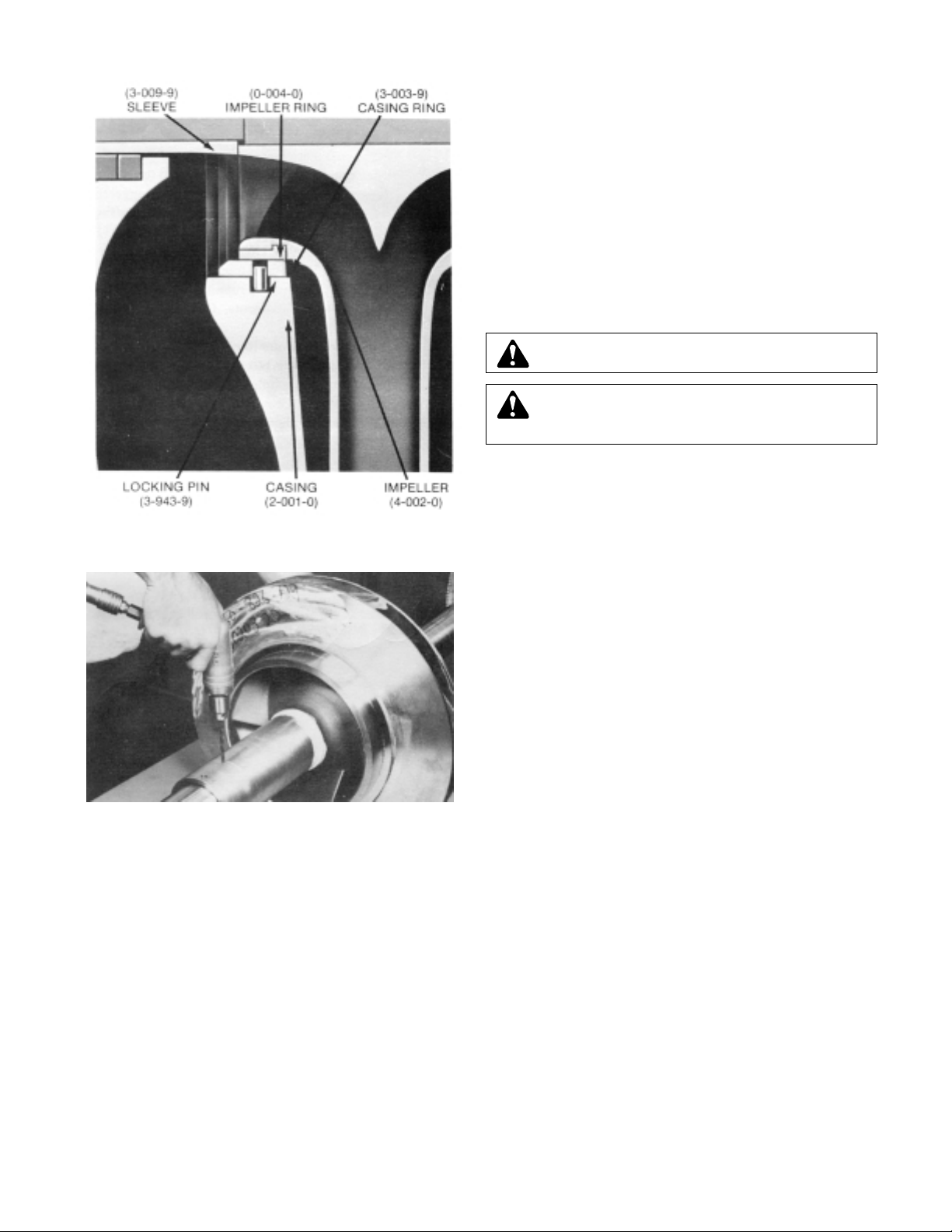
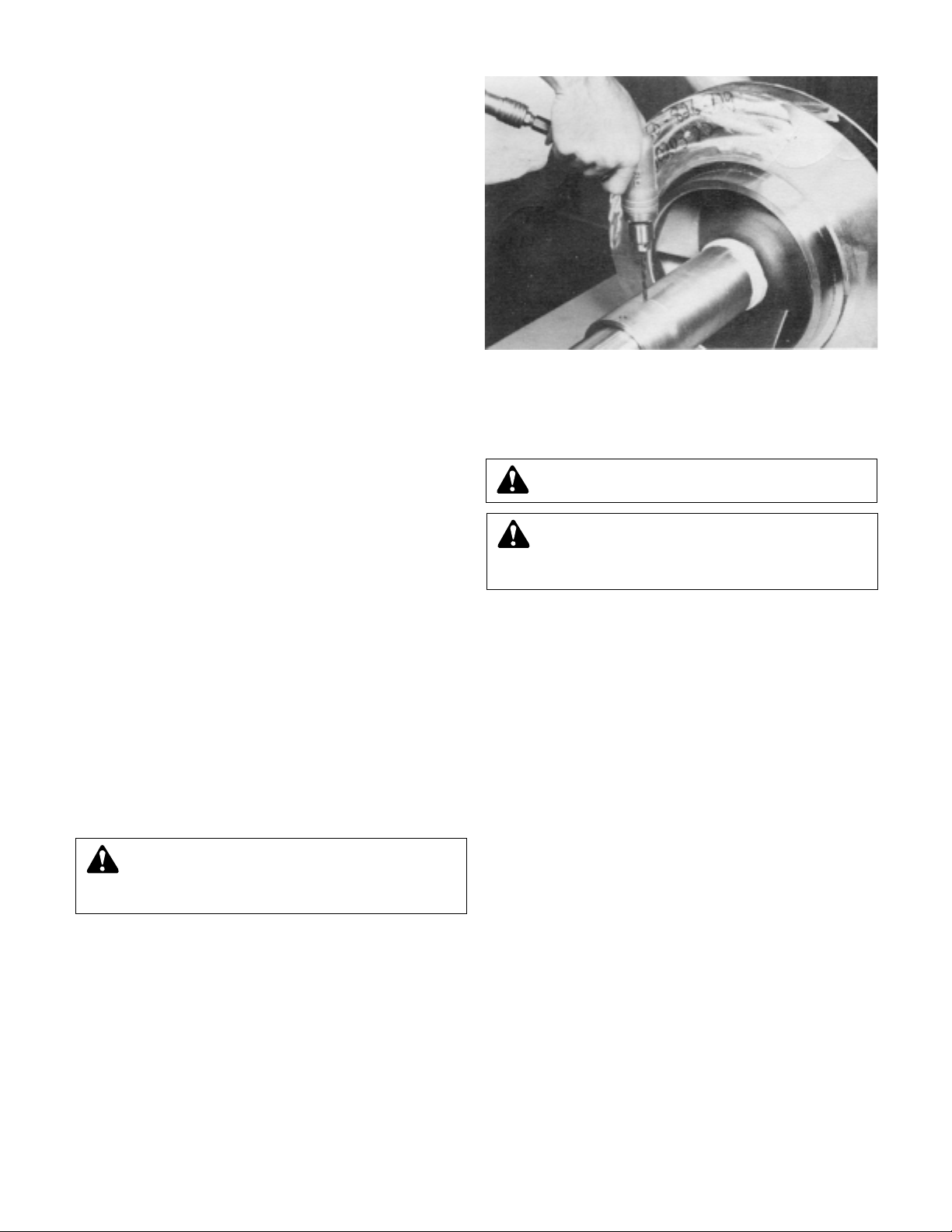
14. Remove casing rings (3-003-9) from impeller (4-002-0).
15. Remove set screw (3-902-9) from shaft nuts. Remove
shaft nuts (3-015-9), O-rings (3-914-9), sleeves (3-009-
9)sleeve gaskets (1-428-1) and impeller (4-002-0).
NOTE: Apply heat uniformly to the shaft sleeve to loosen
the sealant between the shaft and sleeve. DO NOT HEAT
ABOVE 275ºF. To further assist in removing the sleeves,
hold the shaft vertically and drop it on a block of wood.
The impeller weight should force both the impeller and
sleeve from the shaft.
16. Refer to page 26 if pump is equipped with adjustable
rings.
NOTE: For impellers with replaceable rings-remove the
rings (4-004-9) by cutting the rings with a cold chisel. (See
Figure 14).
ASSEMBLY (PUMP WITH PACKING)
All bearings, O-rings, lip seals, gaskets, impeller rings, and
casing wear rings should be replaced with new parts during
assembly. All reusable parts should be cleaned of all foreign
matter before reassembling. The main casing joint gasket can
be made using the upper or lower half as a template. Lay the
gasket material on the casing joint and mark it by pressing it
against the edges of the casing. Trim the gasket, so that it is
flush with the inside edges of the casing.
1. Place impeller key (3-911-1) in shaft (3-007-0).
2. Check the impeller (4-002-0) and casing to determine the
correct impeller rotation (See Figure 16) and locate the
impeller on the shaft per dimension “A”. (See Figure 12)
NOTE: For impeller with replaceable rings, heat each new
ring (4-004-9) and slide it onto the impeller. Hold rings
against the impeller shoulder until they cool. (See Figure
14)
3. Place both shaft sleeve keys (3-911-3) on shaft (3-007-0).
4. Slide sleeve gaskets (1-428-1) onto shaft and against
hubs of impeller.
5. Slide sleeves (3-009-9) onto shaft.
CAUTION: Extreme Temperature Hazard
Allow pump temperature to reach acceptable levels
before proceeding. Open drain valve, do not proceed until
liquid stops coming out of drain valve. If liquid does not
stop flowing from drain valve, isolation valves are not sealing and should be repaired before proceeding. After liquid
stops flowing from drain valve, leave valve open and continue. Remove the drain plug located on the bottom of the
pump housing. Do not reinstall plug or close drain valve
until reassembly is completed. Failure to follow these
instructions could result in property damage and/or moderate personal injury.
CAUTION:
DO NOT REUSE THE BALL BEARINGS.
FIGURE 13 – COMPLETE ROTATING ELEMENT LESS
PACKING AND GLAND
Óä
Page 21
6. Place the sleeve O-ring (3-914-9) onto the shaft, into the
Ê
sleeve counterbor
e. Verify that Dimension “A” (Figure 12) is
Ê
maintained, then using a pin spanner wrench and hammer,
Ê
securely tighten the shaft sleeve nuts (3-015-9). Then, drill
Ê
a shallow recess in the shaft through the set screw hole in
Ê
each of the shaft sleeve nuts. Lock each shaft sleeve nut
Ê
in position with cup point set screws (3-902-9). (See Figure
Ê
15) A low strength sealant, such as Loctite 271, can be
Ê
used to retain set screws.
Ê
7.Assemble casing rings (3-003-9). (See page 26 for
Ê
adjustable rings.)
Ê
8. Start heating bearings (3-026-2) so that they will be ready
Ê
when called for in step 11. Use dry heat from induction
Ê
heat lamps from electric furnace, or a 10-15% soluble oil
Ê
and water solution.
Ê
9. Assemble oil seals (3-177-9) in each bearing cover. Install
Ê
gaskets (3-409-9) on each bearing cover.
Ê
NOTE: Seal lip or pressure side of oil seal must point
Ê
towards the end of the shaft that the oil seal is assembled
Ê
on. (See Figures 25 and 26)
Ê
10. Slide deflectors (3-136-9) and bearing covers (3-018-3, -4)
Ê
on the shaft. Install snap rings (3-915-9). Install thrust
Ê
washer (3-078-9) on the outboard end.
Ê
For ease of assembly and protection of rubber parts while
Ê
sliding rubber parts onto shaft, cover O-ring groove, key-
Ê
ways, and thread with electric tape.
Ê
NOTE: Inboard bearing cover (3-018-3) is approximately
Ê
1/4 inch less in width than the outboard bearing cover
Ê
(3-517-4). This is the only dimensional difference.
Ê
11. Press heated bearing (3-026-2) on shaft against snap ring
Ê
or thrust washer. Install locknut (3-516-4) and lockwasher
Ê
(3-517-4) on outboard end. Make certain locknut is
Ê
secured and then bend over tab on lockwasher.
Ê
12.
PUMPS WITH GREASE LUBRICATION
Cool bearings at room temperature and coat with 2 or 3
Ê
ounces of a recommended grease.
Ê
PUMPS WITH OIL LUBRICATION
Refer to page 26 for installation of oil lubricated parts.
Ê
13. Assemble oil seals (3-177-9) in each bearing housing.
Ê
Refer to
NOTE under number 9 above for direction of oil
Ê
seal.
Ê
14. Slide bearing housings (3-025-2) onto shaft (3-007-0) over
Ê
bearings (3-0262).
Ê
CAUTION: DO NOT EXCEED 275°F.
Ê
CAUTION: These are precision, high quality bearings.
Ê
exercise care at all times to keep them clean and free
Ê
from foreign matter.
Ê
FIGURE 14 – CASING AND IMPELLER RINGS
FIGURE 15 – DRILLING SET SCREW RECESS
2£
Page 22
15. Assemble bearing cover to bearing housing with two cap
Ê
scr
ews (3-904-9).
Ê
16. Replace pump coupling half and key (3-911-2).
Ê
17. Assemble rotating element in lower half casing (2-001-8).
Ê
Correctly locate casing ring pins (3-943-9) in casing main
Ê
joint slot.
Ê
NOTE: Sliding inboard bearing housing toward coupling
Ê
prior to assembling rotating element in casing will ease
Ê
assembly.
Ê
18. Bolt outboard bearing housing in place. Be sure that both
Ê
housing are seated properly in lower half casing.
Ê
19. Bolt inboard bearing housing in place.
Ê
20. Clean the gasket surfaces of the casing. Apply Scotch
Ê
3M-77 spray adhesive or equivalent to the lower half of the
Ê
casing.
Ê
21. Within one minute of spraying, set the gaskets
Ê
(2-123-5, -6) in place on the lower half casing, align the
Ê
holes in the gaskets with the holes in the casing and press
Ê
the gaskets firmly against the lower half casing face in the
Ê
area coated by the adhesive.
Ê
22. Lower upper half casing (2-001-7) into place (See Figure
Ê
16) and locate using the taper dowels (2-916-9) and install
Ê
casing main joint bolts (2-904-9). The casing joint bolts
Ê
should be tightened to the following torques: 300 ft-lb
Ê
minimum for .75"-10 Ferry Cap Counterbore screws
Ê
(Grade 8), 400 ft-lb minimum for 1.0"-8 Ferry Cap
Ê
Counterbore screws (Grade 8). Bolt torquing pattern is
Ê
shown in Figure 10. Before tightening bolts, be sure taper
Ê
dowels are seated properly in reamed holes.
Ê
NOTE: Torque values are essential in obtaining proper
gasket compression so no leakage can occur at main joint.
23. Slide deflectors (3-136-9) toward bearing covers. Allow
rotating clearance of approximately (1/16").
24. Rotate shaft by hand to assure that it turns smoothly and
is free from rubbing and binding.
25. Cut full rings of 5/8 inch square packing so that ends butt,
leaving no gap between packing and casing. Install three
rings of packing (1-924-9) and tap fully to bottom of both
stuffing boxes. (See Figure 17) Stagger joints of each ring
of packing t least 90°. Install seal cage (1-013-2) and be
sure that it will line up with seal water inlet when packing is
compressed. Install remaining three rings of packing with
joints staggered. Assemble glands (1-014-2) square with
stuffing box and pull up tight. Then loosen gland bolts
(1-904-9) to permit packing to expand, and retighten finger
tight. Final adjustment of gland bolts must be done when
pump is running. Allow 30 minutes between adjustments.
(See Figure 18)
26. Assemble seal water lines (0-901-0, 0-950-0, 0-952-0) to
stuffing box and casing. Seal water lines go to inside
holes. (See Figure 12)
27. Check coupling alignment and redowel if necessary.
FIGURE 16 – LOWERING CASING COVER ONTO
LOWER HALF
CAUTION: Double check rotation of pump before
Ê
installing the upper half casing. (Refer to figure 9)
Ê
FIGURE 17 – INSERTING PACKING INTO STUFFING BOX
FIGURE 18 – SECURING PACKING GLAND IN POSITION
2Ó
Page 23

“A”
B. DISMANTLING (PUMP WITH MECHANICAL SEALS
ON SHAFT SLEEVES)
CAUTION: Extreme Temperature Hazard
Allow pump temperatures to reach acceptable levels
before proceeding. Open drain valve. Do not proceed until
liquid stops coming out of drain valve. If liquid does not
stop flowing from drain valve, isolation valves are not
sealing and should be repaired before proceeding. After
liquid stops flowing from drain valve, leave drain valve
open and continue. Remove the drain plug located on the
bottom of the pump housing. Do not reinstall plug or close
drain valve until reassembly is completed. Failure to follow
these instructions could result in property damage and/or
moderate personal injury.
WARNING: Unexpected Startup Hazard
Disconnect and lockout power before servicing.
Failure to follow these instructions could result in serious
personal injury or death, or property damage.
WARNING: Prior to working on pump the power
source should be disconnected with lockout provisions so power cannot be re-energized to the motor. Close
isolating suction and discharge valves. Failure to follow
these instructions could result in property damage, severe
personal injury, or death.
TABLE “A”
Pump Size
Qty.
Dimension A
2-904-9
8x12x22M 26
13.50
8x12x22L 26
10x14x20S 26
12x16x23 26
15.81
14x16x17 24
14x18x23 32
10x14x20L 26 16.60
FIGURE 19 – ASSEMBLY SECTION: PUMP WITH PACKING
15.81
WARNING:Electrical Shock Hazard
Electrical connections to be made by a qualified
electrician in accordance will all applicable codes, ordinances, and good practices. Failure to follow these
instructions could result in serious personal injury or death,
or property damage.
2Î
Page 24

(See Appendix “A” for exploded view.)
Ê
1. Close valves on suction and discharge sides of pump. If
Ê
no valves have been installed, it will be necessary to drain
Ê
the system.
Ê
2. Remove the coupler guard. Refer to section titled “Hex
Ê
Coupler Guard Removal/Installation.
Ê
3. Loosen the capscrews which secure the coupler flanges
Ê
to the coupler hubs. Remove the coupler flanges and
Ê
sleeve by compressing the flanges and pulling out from
Ê
beneath the hubs or by loosening the allen set screws and
Ê
sliding the hubs back on the shafts. Remove the coupler
Ê
hub from the pump shaft.
Ê
4. Drain the pump by opening vent plug (0-910-0) and
Ê
remove drain plugs (0-910-0) on suction and discharge
Ê
nozzle.
Ê
5. Remove seal lines (0-901-0, 0-950-0, 0-952-0), if supplied.
Ê
6. Remove gland bolts (3-904-9) and slide gland (3-014-2)
Ê
away from casing.
Ê
7. Remove all casing main joint cap screws (2-904-1) and
Ê
dowels (2-916-9). Use slot in casing main joint and sepa-
Ê
rate the casing halves with a pry bar. Lift upper half casing
Ê
(2-001-7) by cast lugs.
Ê
8. Remove cap screws (1-904-9) which hold bearing
Ê
housings (3-025-2) to the casing and lift rotating element
Ê
out of lower casing (2-001-08). Rotating element may now
Ê
be moved to a suitable working location.
Ê
9. Pull coupling half and key (3-911-2) off shaft (3-007-0).
Ê
NOTE: A spare rotating element can be installed at this
Ê
point.
Ê
10. Remove cap screws (3-904-9) from bearing covers (3-018-3,
Ê
-4).
Ê
11. Remove bearing housings (3-025-2), locknut (3-516-4),
Ê
and lockwasher (3-517-4). Mount bearing puller and
Ê
remove bearings (3-026-2). Remove thrust washer (3-078-9)
Ê
and snap ring (3-915-9).
Ê
NOTE: Locknut, lockwasher, and thrust washer are not
Ê
used on inboard side.
12. Remove bearing covers (3-018-5, -4) and push oil seals
Ê
(3-177-9) out of bearing covers and coupling and bearing
Ê
housing. Pull deflectors (3-136-9) off shaft.
Ê
13. Remove glands (3-014-2). Loosen set screws and remove
Ê
mechanical seal head assembly (3-402-0). Press mechan
Ê
ical seal seats (3-401-0) from glands.
Ê
14. Remove casing rings (3-003-9) from impellers (4-002-0).
Ê
15. Remove set screw (3-902-9) from shaft nuts. Remove
Ê
shaft nuts (3-015-9), O-rings (3-914-9), sleeves (3-009-9),
Ê
sleeve gaskets (1-428-1), and impeller (4-002-0).
Ê
NOTE: Apply heat uniformly to the shaft sleeve to loosen
Ê
the sealant between the shaft and sleeve.
Ê
To further assist in removing the sleeves, hold the shaft
Ê
vertically and drop it on a block of wood. The impeller
Ê
weight should force both the impeller and sleeve from the
Ê
shaft.
Ê
16. Refer to page 26 if pump is equipped with adjustable
Ê
rings.
Ê
NOTE: For impellers with replaceable rings - remove the
Ê
rings (4-004-9) by cutting the rings with a cold chisel. (See
Ê
Figure 20)
Ê
FIGURE 20 – CASING AND IMPELLER RINGS
CAUTION:
DO NOT REUSE THE BALL BEARINGS.
Ê
CAUTION:
DO NOT EXCEED 275ºF.
Ê
2{
Ê
Page 25
ASSEMBLY (PUMP WITH MECHANICAL SEALS ON SHAFT
SLEEVES)
All bearings, O-rings, seals, gaskets, impeller rings, and cas-
ing wear rings should be replaced with new parts during
assembly. All reusable parts should be cleaned of all foreign
matter before reassembling. The main casing joint gasket can
be made using the lower half as a template. Lay the gasket
material on the casing joint and mark it by pressing it against
the edges of the casing. Trim the gasket so that it is flush with
the inside edges of the casing.
1. Place impeller key (3-911-1) in shaft (3-007-0).
2. Check the impeller (4-002-0) and casing to determine the
correct impeller rotation (See Figure 9) and locate the
impeller on the shaft per dimension “A”. (See Figure 19)
NOTE: For impeller with replaceable rings, heat each new
ring (4-004-9) and slide onto the impeller. Hold rings
against the impeller shoulder until they cool (See Figure
20).
3. Place both shaft sleeve keys (3-911-3) on shaft (3-007-0).
4. Slide sleeve gaskets (1-428-1) onto shaft and against
hubs of impeller.
5. Slide sleeves (3-009-9) onto shaft.
6. Place the sleeve O-ring (3-914-9) onto the shaft, into the
sleeve counterbore. Verify that Dimension “A” (Figure 19)
is maintained, then using a pin spanner wrench and hammer, securely tighten the shaft sleeve nuts (3-015-9).
Then, drill a shallow recess in the shaft through the set
screw hole in each of the shaft sleeve nuts. Lock each
shaft sleeve nut in position with cup point set screws
(3-902-9). (See Figure 21) A low strength sealant, such as
Lotite 271, can be used to retain set screws.
7. Assemble casing rings (3-003-9). (See Figure 24 for
adjustable rings).
8. Install stationary seats (3-401-0) into the glands (3-014-2)
with lapped surface facing outward. Do not scratch or
damage seal faces during assembly. Stationary seat must
bottom squarely in gland.
9. Apply fine coat of silicon grease or equivalent to shaft
sleeve, and slide seal head assembly (3-402-0) over
sleeve. If seal is a John Crane Type 8, set to approximate
dimension shown in Figure 22 and tighten set screws.
Next, install O-rings (3-914-2) onto glands (3-014-2) and
install glands on shaft.
10. Start heating bearings (3-026-2) so that they will be ready
when called for in step 11. Use dry heat from induction
heat lamps or electric furnace, or a 10-15% soluble oil
and water solution.
11. Assemble oil seal (3-177-9) in each bearing cover. Install
gaskets (3-409-9) on each bearing cover.
NOTE: Seal lip or pressure side of oil seal must point
towards the ends of the shaft that the oil seal is assembled on. (See Figures 25 and 26)
12. Slide deflectors (3-136-9) and bearing covers (3-018-3,
-4) on the shaft. Install snap rings (3-915-9). Install thrust
washer (3-078-9) on the outboard end.
For ease of assembly and protection of rubber parts while
sliding parts onto shaft, cover O-ring groove, keyways,
and threads with electrical tape.
CAUTION:
Do not use petroleum based products for installing
mechanical seal head as it may attack the rubber elastomers.
CAUTION:
DO NOT EXCEED 275ºF.
CAUTION:
These are precision, high quality bearings. Exercise
care at all times to keep them clean and free from foreign
matter.
FIGURE 21 – DRILLING SET SCREW RECESS
2x
Page 26

NOTE: Inboard bearing cover (3-018-3) is approximately
1/4 inch less in width than the outboard bearing cover
(3-018-4). This is the only dimensional difference.
13. Press heated bearing (3-026-2) on shaft against snap ring
or thrust washer, Install locknut (3-516-4) and lockwasher
(3-517-4) on outboard end. Make certain the locknut is
secured and then bend over tab on lockwasher.
PUMPS WITH GREASE LUBRICATION
14. Cool bearings at room temperature and coat with 2 or 3
ounces of a recommended grease. Refer to page 26 for
installation of oil lubricated parts.
PUMPS WITH OIL LUBRICATION
Refer to page 26 for installation of oil lubricated parts.
15. Assemble oil seals (3-177-9) in each bearing housing.
Refer to
NOTE under number 11 for direction of oil seal.
16. Slide bearing housings (3-025-2) over bearings (3-026-2).
17. Assemble bearing cover to bearing housing with two cap
screws (3-904-9).
18. Replace pump coupling half and key (3-911-2).
19. Assemble rotating element in lower half casing (2-001-8).
Correctly locate casing ring pins (3-943-9) in casing main
joint slot.
NOTE: Sliding inboard bearing housing toward coupling
prior to assembling rotating element in casing will ease
assembly.
20. Bolt outboard bearing housing in place. Be sure that both
housings are seated in lower half casing.
21. Bolt inboard bearing housing in place. If seal is a John
Crane Type 8, set seal to dimension shown in Figure 22
and tighten set screws.
22. Clean the gasket surfaces of the casing. Apply Scotch
3M-77 spray adhesive or equivalent to the lower half of
the casing.
23. Within one minute of spraying, set the gaskets (2-123-5,
-6) in place on the lower half casing, align the holes in the
gaskets with the holes in the casing and press the gaskets firmly against the lower half casing face in the area
coated by the adhesive.
24. Lower upper half casing (2-001-7) into place (See Figure
23) and locate using the taper dowels (2-916-9) and
install casing main joint bolts (2-904-9). The casing joint
bolts should be tightened to the following torques: 300ftlb minimum for .75"-10 Ferry Cap Counterbore screws
(Grade 8), 400ft-lb minimum for 1.0"-8 Ferry Cap
Counterbore screws (Grade 8). Bolt torquing pattern is
shown in Figure 10. Before tightening bolt, be sure taper
dowels are seated properly in reamed holes.
NOTE: Torque valves are essential in obtaining proper
gasket compression so no leakage can occur at main
joint.
25. Slide deflectors (3-136-9) toward bearing covers. Allow
rotating clearance of approximately 1/16".
26. Rotate shaft by hand to assure that it turns smoothly and
is free from rubbing and binding.
27. Bolt glands (3-014-2) to casing with gland bolts (3-904-9).
28. Assemble seal water lines (0-901-0, 0-950-0, 0-952-0) to
stuffing box and casing. Seal water lines go to outside
holes (See Figure19).
29. Check coupling alignment and redowel if necessary.
CAUTION:
Double check rotation of pump before installing the
upper half casing. (Refer to Figure 9.)
FIGURE 23 – LOWER CASING COVER ONTO LOWER HALF
FIGURE 22 – MECHANICAL SEAL LOCATING DIMENSION
2"
2È
Page 27

ADJUSTABLE WEAR RINGS
Adjustable rings are an assembly of two threaded rings. The
outer, stationary ring is held in the casing by a flange and an
anti-rotation pin in the lower half main joint. The inner,
adjustable ring can be move axially, in either direction, by
rotating it. The ring is held in position by a stainless steel locking pin. All rings have clockwise threads.
Adjustment
When the clearance between the impeller wear face and the
adjustable wearing ring becomes excessive; i.e, approximately
.020" to .030", remove the upper half casing and pull the locking pin.
Rotate the inner rings clockwise to restore .005"-.008" clearance greater than shaft end float between the ring and the
impeller. Drill a new hole in the inner ring for the locking pin.
This is a blind hole - do not drill through. Replace the locking
pin and upper half casing.
Disassembly and Reassembly
Adjustable ring are removed in the same manner as standard
casing rings. They can be separated for cleaning. Adjustable
rings are installed in the pump with stationary and the
adjustable members assembled but not pinned. Turn the
adjustable member counterclockwise to provide maximum
impeller clearance and slide over shaft ends. With the rotating
element in pump, the ring can be adjusted. Be sure that stationary member has its flange flush against casing lower half.
Move rotating element toward outboard end as far as bearings
permit. Screw outboard end adjustable ring toward impeller to
obtain .005"-.008" axial impeller clearance. Drill through stationary ring hole into adjustable ring and insert locking pin.
Move rotating element toward coupling and set coupling end
ring in the same manner.
OIL LUBRICATED BEARINGS
Figures 25 and 26 show a grease lubricated bearing housing
and an oil lubricated bearing housing, respectively. The main
difference between the two is the grease fitting and the oil
ring, respectively.
FIGURE 24 – ADJUSTABLE WEAR RING
FIGURE 25 – GREASE LUBRICATED BEARING HOUSING
FIGURE 26 – OIL LUBRICATED BEARING HOUSING
2Ç
Page 28
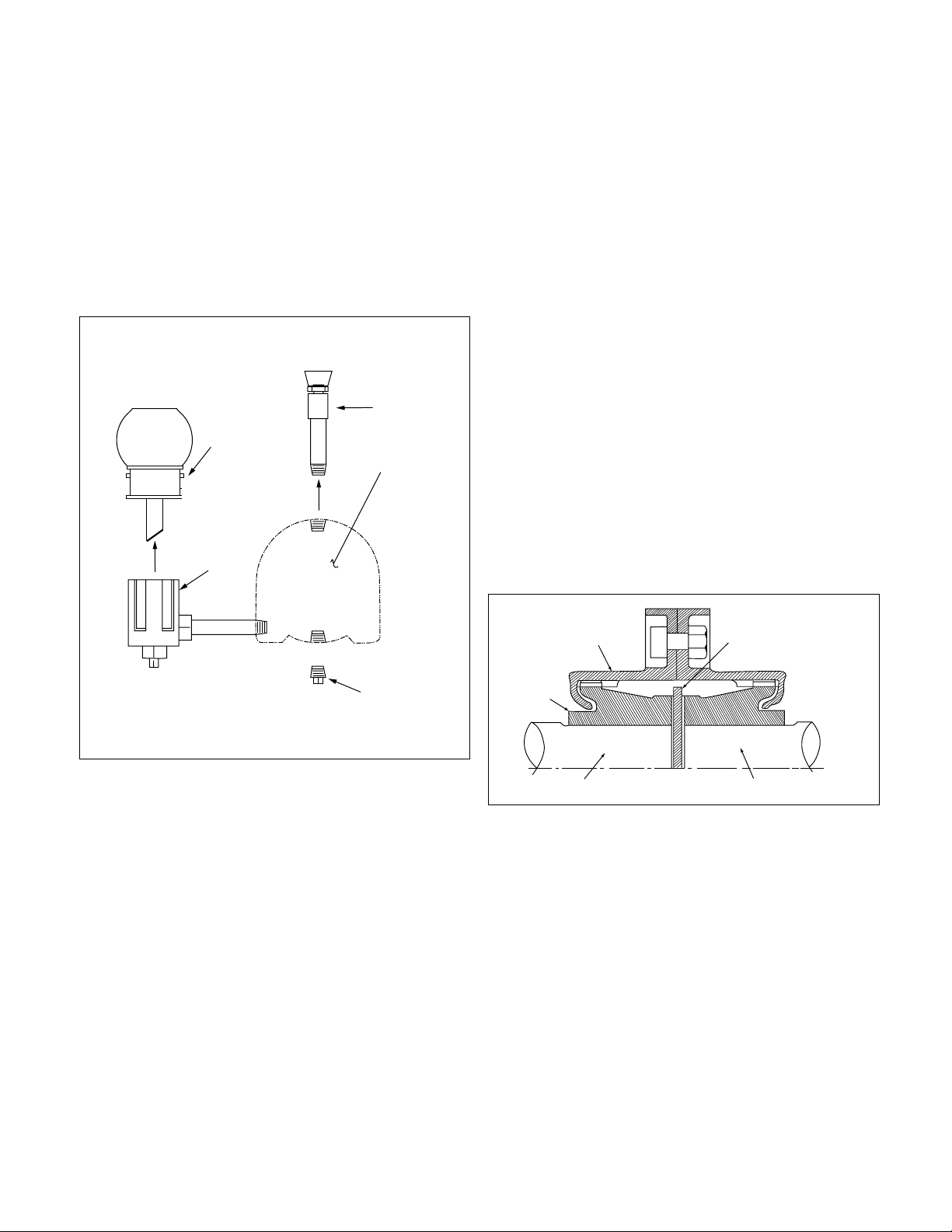
To install the oil ring, place the oil ring in the bearing housing
Ê
dir
ectly under the pipe plug hole. Run a wire through the pipe
Ê
plug hole, around the oil ring and back through the pipe plug
Ê
hole once again. Tie the wire to a metal washer (being a larger
Ê
diameter then the hole) causing the oil ring to become tight
Ê
against the inside top of the bearing housing. Then assemble
Ê
the bearing housing over the bearing. Untie the wire and the
Ê
oil ring will drop down onto the shaft. Check the position of
Ê
the oil ring through the pipe plug hole at the top of the bearing
Ê
housing. The oil ring must be resting on the shaft for correct
Ê
operation. A screwdriver can be used to correct the oil ring
Ê
position, if required.
Ê
The following steps describe how to change the oil for oil
Ê
lubricated bearings. Figure 27 shows a typical oiler assembly.
Ê
1. Remove the vent assembly from the top of the bearing
Ê
housing.
Ê
2. Remove the pipe plug from the bottom of the bearing
Ê
housing.
Ê
3. Unscrew the reservoir and remove.
Ê
4. Flush the oiler and bearing housing with a light grade of
Ê
oil. Flush until all foreign particles have been removed.
Ê
5. Screw the pipe plug and vent assembly back into place.
Ê
6. Fill the reservoir with a good grade of filtered mineral oil.
Ê
Refer to oil lubrication instructions given previously in this
Ê
manual for type of oil.
NOTE: You must fill through Trico reservoir.
Ê
7. Place thumb over reservoir spout, invert and place reser-
Ê
voir on lower casting while removing thumb. Allow reser-
Ê
voir to empty, filling the bearing housing. Several fillings
Ê
of the reservoir may be required before the actual level is
Ê
reached, no more oil will run out of the reservoir.
Ê
8. When reservoir stays full, screw reservoir back into lower
Ê
casting.
Ê
Aperiodic filling of the reservoir is required. When the oil
Ê
becomes dirty, repeat steps 1 through 8.
Ê
LIMITED END FLOAT COUPLING
For units with drivers having sleeve bearings the coupling
Ê
halves are set to limited total shaft axial movement to less
Ê
than one-half of the motor rotor assembly end float. This is
Ê
accomplished by inserting a phenolic disc, or equivalent, of a
Ê
specified thickness between the motor and pump shaft (See
Ê
Figure 28).
Ê
Most HSCS pumps installations use the all metal, gear type
Ê
coupling. Where limited end float gear type couplings are
Ê
used, the coupling hubs are slip-fit onto the pump and motor
Ê
shafts. After installation of the coupling covers and hubs; with
Ê
the motor set on its Magnetic Center, butt the pump and
Ê
motor shafts with the phenolic disc inserted between them.
Ê
(The pump thrust bearing limits end float towards the motor.)
Ê
The thrust bearing of the pump is large enough to carry any
Ê
magnetic thrust developed by the motor when aligned prop
Ê
erly.
Ê
Once the above instructions have been followed out com-
Ê
pletely, the
Alignment Procedures starting on page 6 should
Ê
be followed.
Ê
FIGURE 28 – LIMITED END FLOAT
COUPLING ARRANGEMENT
COVER
HUB
MOTOR SHAFT
PUMP SHAFT
PHENOLIC DISC
FIGURE 27 – OILER ASSEMBLY
RESERVOIR
LOWER
CASTING
VENT
ASSEMBLY
BEARING
HOUSING
PIPE
PLUG
Ê
2n
Page 29

APPENDIX “A”
EXPLODED VIEW
2
Page 30

APPENDIX “A”
REPLACEMENT PARTS LIST
PART NUMBER PART NAME
QUANTITY
PACKING MECH. SEAL
0-901-0 Valve 2 (optional) 2
0-910-0 Pipe Plug 20 18
0-950-0 Pipe Nipple 2 (optional) 2
0-952-0 Tubing 2 (optional) 2
1-013-2 Seal Cage 2
1-014-2 Gland (Packing) 2
1-428-1 Sleeve Gasket 2 2
1-904-9 Gland and Housing Bolt 12 8
1-909-9 Washer, Gland Bolt 4
1-924-9* Packing Ring 12
2-001-7 Casing, Upper Half 1 1
2-001-8 Casing, Lower Half 1 1
2-123-5* Casing Joint Gasket (Suction) 1 1
2-133-6* Casing Joint Gasket (Discharge) 1 1
2-904-1 Cap Screw (Casing) Varies with pump size Varies with pump size
2-916-9 Taper Pin 2 2
3-003-9* Casing Ring 2 2
3-007-0 Shaft 1 1
3-009-9* Shaft Sleeve 2 2
3-014-2 Gland (Mechnical Seal) 2
3-015-9 Shaft Sleeve Nut 2 2
3-018-3 Bearing Housing Cover (Inboard) 1 1
3-018-4 Bearing Housing Cover (Outboard) 1 1
3-025-2 Bearing Housing 2 2
3-026-2* Bearing 2 2
3-078-9 Thrust Washer (Outboard) 1 1
3-136-9 Deflector 2 2
3-177-4* Lip Seal (Outboard Bearing) 1 1
3-177-9* Lip Seal (Bearing) 3 3
3-401-0* Mechanical Seal Seat 2
3-402-0* Mechanical Seal Head 2
3-409-9 Gasket (Bearing Housing Cover) 2 2
3-516-4 Locknut 1 1
3-517-4 Lockwasher 1 1
3-902-9 Set Screw (Shaft Sleeve Nut) 2 2
3-904-9 Gland and Cover Bolt 4 8
3-911-1 Key (Impeller) 1 1
3-911-2 Key (Coupling) 1 1
3-911-3 Key (Shaft Sleeve) 2 2
3-914-2* O-Ring (Gland) 2
3-914-9* O-Ring (Shaft Sleeve) 2 2
3-915-9 Snap Ring 2 2
3-943-9 Spirol Pin 2 2
4-002-0 Impeller 1 1
4-004-9 Impeller Ring 2 (optional) 2 (optional)
*Recommended Spare Parts.
Îä
Page 31

Xylem Inc.
8200 N. Austin Avenue
Morton Grove, Illinois 60053
Phone: (847) 966-3700
Fax: (847) 965-8379
www.xyleminc.com/brands/bellgossett
Bell & Gossett is a trademark of Xylem Inc. or one of its subsidiaries.
© 2012 Xylem Inc. AC8584C November 2012
 Loading...