

Page 1
INSTRUCTION MANUAL
AC8499
INSTALLER: PLEASE LEAVE THIS MANUAL FOR THE OWNER’S USE.
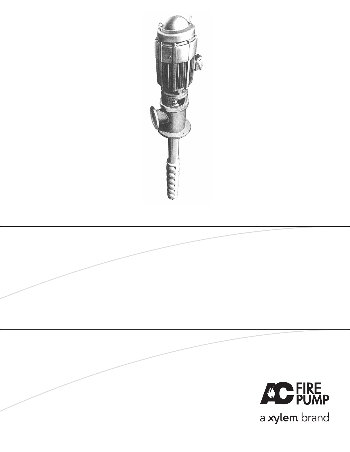
A-C Fire Pump
Vertical Turbine Fire Pump
A-C Model FP
Page 2

2
Safety Apparel:
• Insulated work gloves when handling hot bearings or using
bearing heater.
• Heavy work gloves when handling parts with sharp edges,
especially impellers.
• Safety glasses (with side shields) for eye protection, especially in machine shop areas.
• Steel-toed shoes for foot protection when handling parts,
heavy tools, etc.
• Other personal protective equipment to protect against
hazardous/toxic fluid.
Coupling Guards:
• Never operate a pump without a coupling guard properly
installed.
Flanged Connections:
• Never force piping to make a connection with a pump.
• Use only fasteners of the proper size and proper material.
• Ensure there are no missing fasteners.
• Beware of corroded or loose fasteners.
• Do not operate below minimum rated flow, or with suction/
discharge valves closed.
• Do not open vent or drain valves, or remove plugs while
system is pressurized.
Maintenance Safety:
• Always lock out power.
• Ensure pump is isolated from system and pressure is
relieved before disassembling pump, removing plugs, or
disconnecting piping.
• Use proper lifting and supporting equipment to prevent
serious injury.
• Observe all decontamination procedures.
• Know and follow company safety regulations.
Pump Safety Tips
Note: Observe all cautions and warnings highlighted
in the pump Installation, Operation and Maintenance
Instructions.
Page 3

3
FOREWORD
This manual provides instructions for the Installation, Operation, and Maintenance of the A-C Fire Pumps. This manual
covers a standard product. For special options, supplemental
instructions are available. This manual must be read and
understood before installation and start-up.
This instruction manual covers several different pump models.
Most assembly, disassembly, and inspection procedures are
the same for all the pumps. However, where there are differences, these differences will be noted within the manual. The
design, materials, and workmanship incorporated in the construction of the A-C Fire Pumps makes them capable of giving
long, trouble-free service. The life and satisfactory service of
any mechanical unit, however, is enhanced and extended by
correct application, proper installation, periodic inspection,
condition monitoring and careful maintenance. This instruction
manual was prepared to assist operators in understanding the
construction and the correct methods of installing, operating,
and maintaining these pumps.
The information contained in this book is intended to assist
operating personnel by providing information on the charac-
teristics of the purchased equipment. It does not relieve the
user of their responsibility of using accepted engineering
practices in the installation, operation, and maintenance of
this equipment.
A-C Fire Pumps shall not be liable for physical injury,
damage, or delays caused by a failure to observe the
instructions for installation, operation, and maintenance
contained in this manual.
Warranty is valid only when genuine A-C Fire Pumps parts
are used.
Use of the equipment on a service other than stated in the
order will nullify the warranty, unless written approval is
obtained in advance from A-C Fire Pumps.
For information or questions not covered in this manual, contact A-C Fire Pump Systems at (847) 966-3700.
THIS MANUAL EXPLAINS
• Proper Installation
• Start-up Procedures
• Operation Procedures
• Routine Maintenance
• Pump Overhaul
• Trouble Shooting
• Ordering Spare or Repair Parts
Page 4

4
Warranty
WARRANTY – Company warrants title to the product(s)
and, except as noted with respect to items not of Company’s
manufacturer, also warrants the product(s) on date of shipment to Purchaser, to be of the kind and quality described
herein, and free of defects in workmanship and material.
THIS WARRANTY IS EXPRESSLY IN LIEU OF ALL
OTHER WARRANTIES, INCLUDING BUT NOT LIMITED
TO IMPLIED WARRANTIES OF MERCHANTABILITY
AND FITNESS, AND CONSTITUTES THE ONLY
WARRANTY OF COMPANY WITH RESPECT TO THE
PRODUCT(S).
If within one year from date of initial operation, but not more
than 18 months from date of shipment by Company of any
item of product(s), Purchaser discovers that such item was
not as warranted above and promptly notifies Company in
writing thereof, Company shall remedy such nonconformance
by, at Company’s option, adjustment or repair or replacement
of the item and any affected part of the product(s). Purchaser
shall assume all responsibility and expense for removal, reinstallation, and freight in connection with the foregoing
remedies. The same obligations and conditions shall extend
to replacement parts furnished by Company hereunder.
Company shall have the right of disposal of parts replaced by
it. Purchaser agrees to notify Company, in writing, of any
apparent defects in design, material or workmanship, prior to
performing any corrective action back-chargeable to the
Company. Purchaser shall provide a detailed estimate for
approval by the Company.
ANY SEPARATE LISTED ITEM OF THE PRODUCT(S)
WHICH IS NOT MANUFACTURED BY THE COMPANY
IS NOT WARRANTED BY COMPANY
and shall be
covered only by the express warranty, if any, of the manufacturer thereof.
THIS STATES THE PURCHASER’S EXCLUSIVE
REMEDY AGAINST THE COMPANY AND ITS SUPPLIERS RELATING TO THE PRODUCT(S), WHETHER
IN CONTRACT OR IN TORT OR UNDER ANY OTHER
LEGAL THEORY, AND WHETHER ARISING OUT OF
WARRANTIES, REPRESENTATIONS, INSTRUCTIONS, INSTALLATIONS OR DEFECTS FROM ANY
CAUSE.
Company and its suppliers shall have no obligation as to
any products which has been improperly stored or handled, or which has not been operated or maintained
according to instructions in Company or supplier furnished manuals.
Page 5
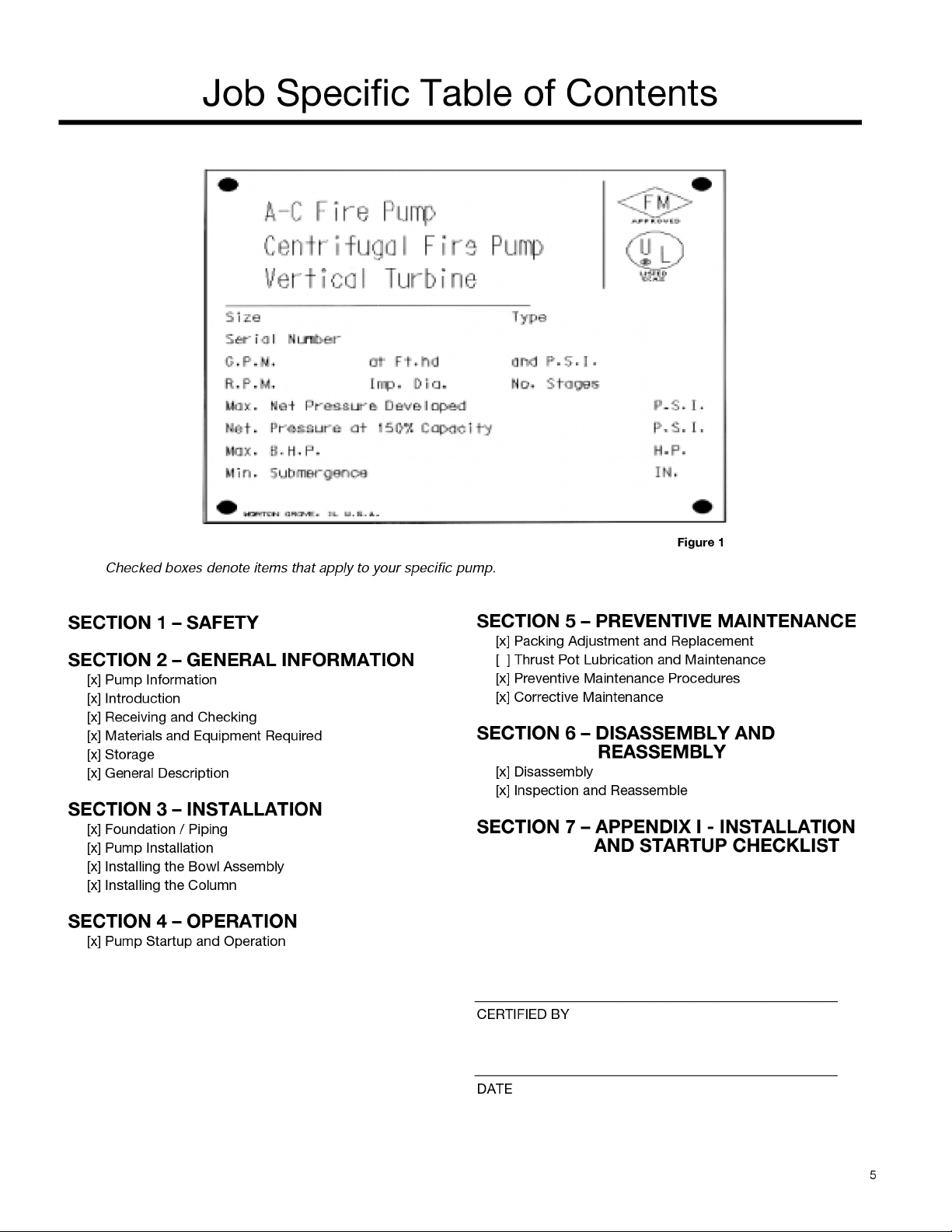
Page 6

6
SECTION 1 - SAFETY Page
Definitions . . . . . . . . . . . . . . . . . . . . . . . . . . . . . . . . . . . . . . . . . . . . . . . . . . . . . . . . . . . . . . . . . . . . . 7
General Precautions . . . . . . . . . . . . . . . . . . . . . . . . . . . . . . . . . . . . . . . . . . . . . . . . . . . . . . . . . . . . . 7
SECTION 2 - GENERAL INFORMATION
Introduction . . . . . . . . . . . . . . . . . . . . . . . . . . . . . . . . . . . . . . . . . . . . . . . . . . . . . . . . . . . . . . . . . . . . 8
Receiving & Checking . . . . . . . . . . . . . . . . . . . . . . . . . . . . . . . . . . . . . . . . . . . . . . . . . . . . . . . . . . . . 8
Materials & Equipment Required . . . . . . . . . . . . . . . . . . . . . . . . . . . . . . . . . . . . . . . . . . . . . . . . . . . . 8
Storage . . . . . . . . . . . . . . . . . . . . . . . . . . . . . . . . . . . . . . . . . . . . . . . . . . . . . . . . . . . . . . . . . . . . . . . 8
General Description . . . . . . . . . . . . . . . . . . . . . . . . . . . . . . . . . . . . . . . . . . . . . . . . . . . . . . . . . . . . . . 9
SECTION 3 - INSTALLATION
Foundation/Piping . . . . . . . . . . . . . . . . . . . . . . . . . . . . . . . . . . . . . . . . . . . . . . . . . . . . . . . . . . . . . . . 10
Pump Installation . . . . . . . . . . . . . . . . . . . . . . . . . . . . . . . . . . . . . . . . . . . . . . . . . . . . . . . . . . . . . . . . 11
Installing the Bowl Assembly . . . . . . . . . . . . . . . . . . . . . . . . . . . . . . . . . . . . . . . . . . . . . . . . . . . . . . 11
Installing the Column . . . . . . . . . . . . . . . . . . . . . . . . . . . . . . . . . . . . . . . . . . . . . . . . . . . . . . . . . . . . . 12
Installing the Discharge Head . . . . . . . . . . . . . . . . . . . . . . . . . . . . . . . . . . . . . . . . . . . . . . . . . . . . . . 13
Stuffing Box Installation . . . . . . . . . . . . . . . . . . . . . . . . . . . . . . . . . . . . . . . . . . . . . . . . . . . . . . . . . . 13
Installing the Driver . . . . . . . . . . . . . . . . . . . . . . . . . . . . . . . . . . . . . . . . . . . . . . . . . . . . . . . . . . . . . . 14
SECTION 4 - OPERATION
Pump Startup & Operation . . . . . . . . . . . . . . . . . . . . . . . . . . . . . . . . . . . . . . . . . . . . . . . . . . . . . . . . 16
SECTION 5 - PREVENTIVE MAINTENANCE
Packing Adjustment & Replacement . . . . . . . . . . . . . . . . . . . . . . . . . . . . . . . . . . . . . . . . . . . . . . . . . 16
Thrust Pot Lubrication & Maintenance . . . . . . . . . . . . . . . . . . . . . . . . . . . . . . . . . . . . . . . . . . . . . . . 17
Preventive Maintenance Procedures . . . . . . . . . . . . . . . . . . . . . . . . . . . . . . . . . . . . . . . . . . . . . . . .17
Corrective Maintenance . . . . . . . . . . . . . . . . . . . . . . . . . . . . . . . . . . . . . . . . . . . . . . . . . . . . . . . . . . 18
SECTION 6 - DISASSEMBLY & REASSEMBLY
Disassembly . . . . . . . . . . . . . . . . . . . . . . . . . . . . . . . . . . . . . . . . . . . . . . . . . . . . . . . . . . . . . . . . . . . 19
Inspection & Reassembly . . . . . . . . . . . . . . . . . . . . . . . . . . . . . . . . . . . . . . . . . . . . . . . . . . . . . . . . . 20
SECTION 7 - REPAIR PARTS
Repair Parts . . . . . . . . . . . . . . . . . . . . . . . . . . . . . . . . . . . . . . . . . . . . . . . . . . . . . . . . . . . . . . . . . . . . 22
SECTION 8 - APPENDIX I
Installation & Startup Checklist . . . . . . . . . . . . . . . . . . . . . . . . . . . . . . . . . . . . . . . . . . . . . . . . . . . . 25
Index
Page 7
7
Section 1 - Safety
These pumps have been designed for safe and reliable
operation when property used and maintained in accordance
with instructions contained in this manual. A pump is a pressure containing device with rotating parts that can be hazardous. Operators and maintenance personnel must realize
this and follow safety measures. A-C Fire Pumps shall not be
liable for physical injury, death, damage or delays caused by
a failure to observe the instructions in this manual.
Throughout this manual the words WARNING, CAUTION,
and NOTE are used to indicate procedures or situations
which require special operator attention:
NOTE: Operating procedure, condition, etc. which is essential
to observe.
EXAMPLES:
• NEVER apply heat to remove impeller. It may explode
dueto trapped liquid.
• NEVER use heat to disassemble pump due to risk of
explosion from trapped liquid.
• NEVER operate pump without coupling guard correcly
installed.
• NEVER operate pump beyond the rated conditions to
which the pump was sold.
• NEVER start pump without proper prime (sufficient liquid in
pump casing).
• NEVER run pump below recommended minimum flow or
when dry.
• ALWAYS lock out power to the driver before performing
pump maintenance.
• NEVER operate pump without safety devices installed.
• NEVER operate pump with discharge valve closed.
• NEVER operate pump with suction valve closed.
• DO NOT change conditions of service without approval of
an authorized A-C Fire Pumps representative.
Definitions
General Precautions
WARNING: Operating procedure, practice, etc., which,
if not correctly followed, could result in personal injury
or loss of life.
CAUTION: Operating procedure, practice, etc. which,
if not followed, could result in damage or destruction
of equipment.
WARNING: Personal injuries will result if procedures
outlined in this manual are not followed.
CAUTION: Throttling flow from the suction side may
cause cavitation and pump damage. NOTE: Proper
alignment is essential for long pump life.
WARNING: Pump shall never be operated without
coupling guard installed correctly.
Page 8

8
The pump should be carefully supported prior to unloading
from the carrier. Handle all components carefully. Inspection
for damage of the shipping crate should be made prior to
unpacking the pump. After unpacking, visually inspect the
pump and check the following:
1. Contents of the pump assembly against the packing list.
2. All components against damage.
3. All shafting for straightness and damage, should the crate
be broken or show careless handling.
Any shortages or damages should be immediately called to
the attention of the local freight agent of the carrier by which
the shipment arrived and proper notation made on the bill.
This will prevent any controversy when claim is made and
facilitate prompt and satisfactory adjustment
Receiving & Checking
Materials & Equipment Required
The material and equipment necessary for installation of the
pump will vary with the size of the pump and the type of
installation.
The following list of standard tools and supplies is offered
only as a guide.
BULK MATERIAL
• Anti-Galling lubricant (such as Dow Corning
"MOLYKOTE")
• Thread Compound
• Lubrication Oil
• Turbine Oil
Grease
RIGGING EQUIPMENT
• Mobile power hoist, traveling crane, or derrick
• Drag line and blocks
• Elevator clamps, if unit is unassembled
• Clevises – for use with eyebolts
• Timbers – size, length, and quantity to support long pump
parts on the floor
• I-Beams or timbers to support pump over installation
HAND TOOLS
• Pipe wrenches
• Feeler gauges
• Set of mechanics tools including: files, wire brush, pliers,
wire cutters and pocket knife
• Clean rags
OPTIONAL TOOLS TO FACILITATE PUMP ASSEMBLY
AND DISASSEMBLY
• Dial indicator to assist in motor and pump alignment
• Collet driver to assist in bowl assembly and disassembly
for pumps with taper lock impellers only
Storage
A-C Fire Pumps carefully preserves and protects its products
for shipment. However, the effective life of the preservatives
applied at the factory can vary from 3 to 18 months depending
on the severity of the environment in which the equipment is
stored. This section provides procedures for preparation prior
to storage and maintenance during storage of A-C Fire
Pumps. These procedures are necessary to protect the preci-
sion parts of the pumps. Specific procedures for storing
motors, gearheads, and engines, should be obtained from the
equipment manufacturer. This section is intended to be of
general assistance to users of A-C Fire Pumps. It shall not
modify, amend and/or otherwise alter the scope of A-C Fire
Pumps warranty responsibilities to the purchaser in any way
whatsoever.
Section 2 - General Information
Introduction
The design, material, and workmanship incorporated in the
construction of A-C Fire Pumps makes them capable of giving
long, trouble free service. The life and satisfactory service of
any mechanical unit, however, is enhanced and extended by
correct application, proper installation, periodic inspection
and careful maintenance. This instruction manual was prepared to assist operators in understanding the construction
and the correct methods of installing, operating, and maintaining these pumps.
Study thoroughly Sections 1 through 6 and carefully follow the
instructions for installing and operating. Sections 5 contains
answers to trouble shooting and maintenance questions.
Keep this instruction manual handy for reference.
CAUTION: The information in this manual is intended
to be used as a guide only. If you are in doubt, consult your A-C Fire Pumps representative for specific information about your pump.
WARNING: Rotating components of the pump
assembly must be covered with a suitable rigid guard
to prevent injury to personnel.
WARNING: A-C Fire Pumps will not be liable for any
damages or delay caused by failure to comply with
the provisions of this instruction manual.
Page 9

9
STORAGE PREPARATION
A-C Fire Pumps require proper preparation for storage and
regular maintenance during storage. The pump shall be considered in storage when it has been delivered to the job site
and is awaiting installation.
Preferably, the storage area shall be paved, well drained and
free from flooding, and be indoors whenever possible.
Weatherproof coverings used for outdoor storage shall be
flame resistant type sheeting or tarpaulins. They shall be
placed so as to provide good drainage and air circulation and
shall be tied down to protect from wind damage.
Storage area shall be maintained in a clean condition at all
times.
Pumps and/or component parts shall be placed on skids,
pallets, or shoring to permit good air circulation.
Pumps and/or component parts shall be sorted so as to permit ready access for inspection and/or maintenance without
excessive handling.
Pumps and/or component parts stacked during storage shall
be arranged so that the racks, containers, or crates bear full
weight without distortion of pumps or parts. Identification
markings must be readily visible. Any cover removed for internal access shall be replaced immediately.
Pump and bowl assembly shafting shall be rotated counter
clockwise, as a minimum, once a month. Shaft shall not be left
in the same previous position, nor in the extreme raised or
lowered lateral position. Shaft should rotate freely.
NOTE: For further information on these procedures contact your A-C Fire Pumps representative.
RECOMMENDED STORAGE PROCEDURES
Controlled storage facilities should be maintained at an even
temperature 10ºF (6ºC) or more above the dew point with
relative humidity less than 50% and little or no dust. (If these
requirements can not be met the pump is to be considered in
uncontrolled storage.)
For uncontrolled storage periods of 6 months or less, the
pump is to be inspected periodically to insure that all preservatives are intact.
All pipe threads and flanged pipe covers are to be sealed with
tape.
The pump must not be stored closer than six inches (15 cm)
from the ground.
UNCONTROLLED LONG TERM STORAGE
PREPARATIONS
When applicable to the pump, storage periods over six
months require the preceding storage procedure and storage
preparation plus the following:
Inspect the lube oil and seal flush piping and either fill the piping with rust preventative oil, or re-coat the piping periodically
to prevent corrosion.
Place 10 pounds (4.5 kg) of moisture absorbing desiccant or
5 pounds (2.3 kg) of vapor phase inhibitor crystals near the
center of the pump. If the pump is assembled, place an additional one pound (0.5 kg) in the discharge nozzle securely fastened to the discharge elbow.
Install a moisture indicator near the perimeter of the pump.
Cover the pump with 6 mil (0.15 mm) minimum thickness
black polyethylene or equal and seal it with tape. Provide a
small ventilation hole approximately
1
/2 inch (12 mm) diameter.
Provide a roof or shed shelter to protect from direct exposure
to the elements.
General Description
The model FP pump is a vertical turbine fire pump, which is
designed to meet many wide ranges of service.
DRIVERS
When packed stuffing boxes are used with open lineshaft
pumps, hollow shaft motors or right angle gear drives, are
often used with a separate driveshaft through the driver and
connected to the pump by a rigid coupling.
DISCHARGE HEAD
The discharge head is either a cast iron head or a fabricated
‘F’ type head. Ports are provided for connecting the discharge
gauge and stuffing box bypass return. The driver support portion of the discharge head is designed with large hand holes
for easy mechanical seal or stuffing box adjustment.
COLUMN
Threaded or flanged column construction provides positive
shaft and bearing alignment. Bearings are spaced to provide
vibration free operation. This will insure long bearing life and
reduced shaft wear. The lineshaft is supported within the
column by use of bearing retainers in the column assembly.
BOWL ASSEMBLY
The bowls are generally of flanged construction for accurate
alignment and ease of assembly and disassembly. Impellers
are enclosed. For temperatures over 180ºF (82ºC) and in the
larger size bowls, impellers are keyed to the shaft.
THRUST POT
A thrust pot is utilized when the driver is not designed to carry
the pump thrust.
Page 10

BASE (SOLE PLATE) INSPECTION
Sub Base and Sole Plate are terms in common use to describe a general class of solid steel plates mounted in grout
(or bolted to steel structures) at the pump-foundation interface.
1. Remove the Sub Base from the Pump Discharge Head,
when shipped assembled.
2. Completely clean the underside of the Sub Base. It is
sometimes necessary to coat the underside of the Sub
Base with an epoxy primer. (This is available as an option.)
3. Remove the rust preventative solution from the machined
topside with an appropriate solution.
SITE WITH CONCRETE FOUNDATION
1. A pump should have adequate space for operation, main
tenance, and inspection.
2. Sub Base mounted pumps are normally grouted on a concrete foundation, which has been poured on a solid footing. The foundation must be able to absorb any vibration
and to form a permanent, rigid support for the pumping
unit.
3. The foundation must be of adequate strength to support
the complete weight of the pump, plus the weight of the
liquid passing through it. A typical installation will have
bolts with a pipe sleeve 2
1
/
2 times the bolt diameter embed
ded in the concrete, sized and located in accordance with
the dimensions given on the Pump Certified Outline
Drawing, if provided. The pipe sleeve allows movement for
final positioning of the foundation bolts to conform to the
holes in the Sub Base flange. See Figure 2.
4. Remove water and/or debris from anchor bolt holes/
sleeves prior to grouting. If the sleeve type bolts are being
used, fill the sleeves with packing or rags to prevent grout
from entering.
5. Carefully lower the Sub Base onto the foundation bolts.
Hand tighten the bolt nuts.
6. Leveling the Sub Base may be done by several methods.
Two common methods are:
A. Leveling the wedges. This is shown in Figure 3.
B. Leveling nuts on the anchor bolts.
Regardless of the method, a machinist level must be used
for leveling.
NOTE: When using a machinist level, it is important that
the surface being leveled is free of all contaminants, such
as dust, to ensure an accurate reading.
7. Level the Sub Base in two directions at 90 degrees on the
machined surface. The levelness tolerance is 0.005 inches
per foot for commercial, and 0.001 inches per foot for API.
SUB BASE GROUTING
1. Inspect foundation for dust, dirt, oil, chips, water, etc.,and
remove any contaminants. Do not use oil-based cleaners
as grout will not bond to it. Refer to grout manufacturer’s
instructions.
2. Build dam around foundation. Thoroughly wet foundation.
3. Pour grout between Sub Base and concrete foundation, up
to level of dam. Remove air bubbles from grout as it is
poured by puddling, using a vibrator, or pumping the grout
into place. Non-shrink grout is recommended.
4. Allow grout to set at least 48 hours.
5. Tighten foundation bolts.
10
Section 3 - Installation
Foundation /Piping
Figure 2
Figure 3
Page 11

11
SITE WITH STRUCTURAL STEEL FOUNDATION
1. When the pump is mounted directly on a structural steel
frame, pumps shall be located directly over, or as near as
possible to the main building members, beams, or walls.
be bolted to the support to avoid distortion, prevent vibration, and retain proper alignment.
2. If a Sub Base is being bolted to a structural steel foundation, or the Sub Base is not grouted to the concrete foundation, use shims for leveling the plate.
PIPING
Guidelines for piping are given in the "Hydraulic Institute
Standards", available from: Hydraulic Institute, 9 Sylvan Way,
Parisppany, NJ 07054-3802 and must be reviewed prior to
pump installation.
1. All piping must be supported independently of, and line up
naturally with, the pump flange.
2. DO NOT connect piping to pump until grout has hardened
and pump hold down bolts have been tightened.
3. It is suggested that expansion loops or joints, if used, be
properly installed in discharge line when handling liquids at
elevated temperatures, so linear expansion of piping will
not draw pump out of alignment.
4. Carefully clean all pipe parts, valves and fittings, and pump
branches prior to assembly.
5. Isolation and check valves should be installed in discharge
line. Locate the check valve between isolation valve and
pump, this will permit inspection of the check valve. The
isolation valve is required for regulation of flow, and for
inspection and maintenance of pump. The check valve
prevents pump or seal damage due to reverse flow through
the pump when the driver is turned off.
6. Increasers, if used, should be placed between pump and
check valves.
7. Cushioning devices should be used to protect the pump
from surges and water hammer if quick-closing valves are
installed in the system.
FINAL PUMP CHECK
1. Rotate shaft several times by hand to be sure that there is
no binding and all parts are free.
2. Check alignment, per the alignment procedure outlined on
page 16, to determine absence of pipe strain. If pipe strain
exists, correct piping.
Pump Installation
Pumps 20 feet (6m) or less in length are usually shipped
assembled, with the exception of the driver and packing.
When provided, refer to the Certified Pump Outline for the
applicable base plate plan for location of anchor bolt holes.
INSTALLING A PARTIALLY ASSEMBLED PUMP
1. If a baseplate was supplied, install as described in
Foundation/Piping Section page 10.
2. Clean the plate mounting flange and clean bottom surface
of discharge head mounting flange.
3. Sling through discharge hand holes or thread two eyebolts
through bolt holes in mounting flange and hoist unit into
position over foundation.
NOTE: Eyebolts or sling should be rated to handle in excess
of the pump weight (see Order Outline Drawing, if provided).
4. Lower the unit and carefully guide it so that unit does not
strike the sides of the base plate. Continue to lower unit
until the discharge head base flange engages and rests
firmly on the plate, then secure with capscrews provided.
5. When a lineshaft is shipped separately check shaft for
straightness; average total runout should not exceed
0.005" T.I.R. (0.127mm) for every 10 feet (3m). Shaft
straightness must be within tolerance prior to installation.
6. Remove stuffing box (if installed), and carefully slide shaft
through top column bearing retainer and thread into coupling after replacing stuffing box or seal housing.
Useextreme care not to damage bearing retainer.
7. Refer to the remainder of this manual for complete assembly, startup, maintenance, disassembly, and recommended
lubricants for the pump.
Installing Bowl Assembly
The following bowl installation instructions apply to pumps
shipped disassembled.
1. Prior to installing the bowl assembly, check that all capscrews are tight and any integral piping is installed.
Remove all accumulated dust, oil, or other foreign
material
from the external surfaces.
WARNING: Never draw piping into place by forcing at
the flange connections of the pump. Pipe strain will
adversely effect the operation of the pump resulting in physical injury and damage to the equipment.
WARNING: Do not work under a heavy suspended
object unless there is positive support and safe guards
which will protect personnel should a hoist or sling fail.
CAUTION: Do not attempt to lift bowl assembly by
the pump shaft. This can result in damaging the pump
shaft.
Page 12

12
2. Place two I-beam supports across the base plate opening,
strong enough to safely support the weight of the entire
pump assembly. These I-beams should be connected by
threaded rods and nuts, so as to clamp them firmly together
for the portion to be supported. (See Figure 4).
3. Put in place a suitable hoist or derrick over base plate
opening. Place the elevator clamps just below the dicharge
bowl flange or install two threaded eye bolts through bolt
holes in flange 180º apart.
4. Attach sling to elevator clamps or eye bolts and hoist into
position over foundation opening (See Figure 4).
5. Carefully lower bowl assembly, guiding the unit so it does
not strike the sides of the opening. Continue to lower bowl
assembly until the elevator clamps or discharge bowl
flange rests firmly on the I-beam supports.
6. Place a cover over the discharge bowl opening to prevent
entrance of dirt or other foreign matter.
Figure 4
Installing the Column
OPEN LINESHAFT
Pump lineshafts are connected with threaded couplings.
When provided, see the Certified Pump Outline Drawing for
the number of column and shaft sections required:
1. Check the headshaft (608) and lineshaft (646) for straightness. Average total runout should be less than 0.0005" TIR
(0.013 mm) per foot (0.305 m), not to exceed 0.005" T.I.R.
(0.127 mm) for every 10 feet (3 m) of shafting.
2. Apply a thin film of oil to lineshaft (646) and coupling (649)
threads (in non-galling material, or Molykote if galling
material). Start threads manually until resistance is felt. A
fine wire inserted in the drill hole at the center of the coupling can be used as a gauge to determine when the coupling is correctly positioned on the shaft. Run the upper
lineshaft into the coupling until it is hand tight. Remove the
wire after installing the coupling. Complete the joint using a
pair of pipe wrenches, one on the top of pump shaft (660)
and the other on the coupling (649).
3. Use chain wrenches (clamp type) attached to the shaft to
tighten the two shafts, using care not to damage any bearing journal areas. NOTE: Shaft threads are left-handed.
4. Hoist column section over bowl assembly. Lower column
over lineshaft until column flange engages the discharge
bowl. Manually thread the column into the discharge bowl.
Complete joint by tightening column with chain tongs until
the end of the column butts firmly against discharge bowl.
5. For flanged column, install two eyebolts diametrically
opposite the upper flange of the bottom volume. Attach a
sling to the eyebolts and to the hoist hook.
Lower column section until the flange engages the flanged
top bowl register. Insert as many bolts through both
flanges as possible. Lift column assembly high enough to
allow rotation of the supports. Install and tighten remaining
capscrews gradually in diametrically opposite pairs until all
are uniformly tight.
6. Lift the assembly and remove the elevator clamp or supports and slowly lower the bowl and column assembly.
Place supports on the base plate and continue to lower the
assembly until the column elevator clamps or colum flange
comes to rest on the supports. Place an elevator clamp
under the column pipe and allow it to butt firmly against
the column pipe coupling
7. Place the bearing retainer over the shaft and locate it in the
column coupling recess.
Flanged columns will normally have separate bearings
retailers, which will fit into the female registers in the
flanges on both ends of the column. Large flange column
will have the bearing retainer integral with the column. The
top flange of the column will have a male register and the
bottom flange of the column will have a female register.
For metal bearings, pour a small amount of oil between the
bearing and shaft. Install threaded coupling on protruding
end of lineshaft.
8. Repeat the preceding procedures until all column sections
required have been installed. For deeper set pump units, a
stub shaft will be the top shaft.
CAUTION: Do not drop any foreign object into the
bowl assembly. Such an object can cause serious
damage to the pump and any downstream components
Any foreign object dropped into the bowl assembly must be
retrieved prior to continuing assembly.
CAUTION: Use "MOLYKOTE" Dow-Corning or equal
for all galling material such as 316 stainless steel.
Page 13

13
Installing the Discharge Head
OPEN LINESHAFT
1. A-C Fire Pumps are provided with either a cast iron or fab
steel type head. Install the discharge head as follows:
2. If the stuffing box is assembled to the head, remove it and
all attached piping. See Figure 5 for the stuffing box provided for the A-C Fire Pump being assembled.
3. Remove coupling guard if provided. Attach a sling through
windows (hand holes) or thread two eyebolts in the head
driver support mounting holes diametrically opposite and
hoist discharge head over the protruding headshaft.
4. Orient the discharge head in the required position and
lower the head, centering the vertical hole with the headshaft or stub shaft protruding above the column. For
threaded column, continue to lower the discharge head
until the large threaded hole in the bottom of the discharge
head rests squarely on top of the column. Rotate the discharge head, screwing it onto the column, butting the top
of the column tightly against the discharge head.
5. For flanged column, continue to lower the discharge head
until the discharge head engages the column. Install capscrews and secure discharge head to the column flange.
Tighten capscrews gradually in diametrically opposite
pairs.
6. Lift pump assembly high enough to allow rotation of the
supports. Realign and lower assembly. Install and tighten
remaining capscrews. Repeat rotation and tightening procedure, until all capscrews are uniformly tight.
7. Using a device with the capacity to support the weight of
the entire pump assembly, hoist bowl, column, and head
assembly and remove supports.
NOTE: Eyebolts or sling should be rated to handle in
excess of the pump weight.
8. Lower bowl, column and head assembly, until discharge
head mounting flange engages base plate. Secure discharge head to mounting plate. Check the levelness of the
discharge head in all directions, utilizing a spirit level
across the driver mounting surface of the discharge head.
Stuffing Box Installation
Assemble stuffing box in accordance with Figure 5, below.
STANDARD CONSTRUCTION
1. Position gasket on discharge head. Slide stuffing box
(616) down over shaft and into position on the gasket.
Secure stuffing box with capscrews.
2. Insert lantern ring (621) into stuffing box. Be sure it is properly positioned so that it aligns with the lubrication passage
in the stuffing box.
3. Grease the packing rings (620) for easier installation.
4. Twist the packing ring sideways to get it around the shaft
easily. Start the first ring into the stuffing box. When the
entire ring is worked in using the fingers, tamp it down
using a split wood bushing (or equal) and push the packing
ring down firmly. It must seal on the shaft and bore of the
stuffing box. Install all five (5) rings in this manner. Stagger
ring joints 90º apart. The split gland may be used as a tamper for the top ring.
5. Install the split gland and threaded nuts on the split gland
studs. Tighten nuts then relieve the nuts and tighten finger
tight. Attach bypass line to tube fitting in the stuffing box.
6. Final adjustment of the stuffing box must be made at pump
start up. This final adjustment applies to all stuffing box
styles.
7. A properly packed stuffing box should be loose enough to
allow the shaft to be turned manually.
Figure 5
CAUTION: Do not bend or scrape the shaft protruding
above the column. This could result in bending or
damaging the shaft.
CAUTION: Check that the split gland is square in
the stuffing box. Cocking can cause uneven compres-
sion of packing and damage to the shaft or sleeve.
CAUTION: Do not overtighten packing or excessive
wear can occur on the shaft or sleeve.
Page 14

INSTALLATION OF A HOLLOW SHAFT DRIVER
This refers to either VHS type electric motors or hollow shaft
type gear drives.A small paragraph will be devoted to combination electric motor and right angle gear drives.
NOTE: When pump is supplied with a thrust pot, do not
secure driver to discharge head until after the thrust pot and
flexible coupling are installed.
1. The driveshaft projecting through the quill or hollow-shaft
of the driver is separate from the pump shaft and connected to same by a rigid flanged coupling or threaded
coupling.
2. Driver support. When a driver support is furnished and not
installed, proceed as follows:
A. Hoist driver support, inspect the mounting surfaces,
register, and clean these surfaces thoroughly.
B. Install driver support on discharge head and secure with
capscrews provided.
3. Attach a sling to the lifting lugs of driver, hoist motor,
inspect the mounting surface, register, and shaft extension, and clean these surfaces thoroughly. If any burrs are
found, remove burrs with a smooth mill file, cleaning thoroughly afterward.
4. Orient the motor conduit box in the required position. Align
the motor mounting holes with the mating tapped holes on
the discharge head. Lower the motor until the registers
engage and the motor rests on the discharge head. Secure
motor with capscrews provided.
5. On drivers having a non-reverse ratchet or pins, manually
turn the driver shaft clockwise viewed from the top until the
non-reverse ratchet or pins fully engage.
6. Lubricate motor bearings in accordance with instructions
given on lubrication plate attached to the motor case.
7. The driving mechanism of all hollow shaft drives is shown
on Figure 6. The driveshaft (606) extends up through the
quill or hollow shaft of the motor (or gear drive) and is held
in place by an adjusting nut (604), which not only carries
all the static and hydraulic thrust of the impellers and
shaft but also provides the adjustment for the impeller
clearances.
8. After lowering and orienting the motor and/or gear drive as
explained above, remove the drive coupling and the hold
down bolts as shown in Figure 6.
9. Screw the adjusting nut (604) loosely onto the end of driveshaft (606). Clean thoroughly and attach a light line below
the nut. Lower the driveshaft through the motor quill
shaft. Examine closely for dirt or burrs between shaft
ends.
10.
Apply a suitable thread compound to the driveshaft
threaded coupling. Thread the driveshaft into the threaded
coupling and tighten.
COMPLETION OF INSTALLATION OF A
HOLLOW SHAFT DRIVER
1. Remove lifting sling and see if driveshaft centers inside
the motor quill shaft within 0.06" (1.5mm). If it does not,
misalignment is indicated.
2. Any driveshaft misalignment with driver quill shaft could
be caused by a bent driveshaft, burrs, or foreign matter
between shaft ends or any of the mounting flanges:
motor to mount, mount to discharge head, discharge
head mounting to plate or the plate itself could be out of
level. If the latter, shimming between it and discharge
head base, will correct it. Also, check concentricity of
motor to motor stand to discharge head.
3. With the motor in place and the driveshaft projecting
through the motor quill shaft, connect up the electricity
and check motor rotation. This should be counterclockwise when viewed from the top. See arrow on pump
name plate. If motor does not rotate counter-clockwise,
you can change the rotation by interchanging any two
leads (for three phase only, for single phase motors see
motor manufacturer’s instructions.)
4. Install motor drive coupling, inserting the ratchet pins if a
non-reverse ratchet is used. Match the coupling lugs with
corresponding holes in motor. Tighten down hold down
bolts evenly, making sure drive coupling is properly
seated in the register fit.
14
Installing the Driver
Figure 6
WARNING: Do not work under a heavy suspended
object unless there is a positive support and safeguards which will protect personnel should a hoist or sling
fail.
CAUTION: Never check motor rotation with the
drive coupling in place. The bore clearance between
the drive coupling and the pump shaft O.D. is so close that
should the motor spin with this shaft stationary, galling and
locking together is very likely to take place.
Page 15

15
5. Fit gib key (760) into keyway, by filing if necessary, to
where there is a snug but sliding fit. This key must be able
to be removed by gentle leverage with a screwdriver under it.
6. Be careful that the gib key (760) is not too high so as to
hold up the adjusting nut (604) from seating on the drive
coupling. If it is, cut off some of it.
7. Install adjusting nut (604) to hand tight.
GEAR DRIVES WITH ENGINES
1. The procedure for installing a hollow shaft gear is exactly
the same as for the motor.
2. Checking pump rotation is very simple matter. Check the
arrows of rotation on the engine. Throw out the clutch, take
a bar and jack over the flexible driveshaft in direction of
engine rotation, and note if it turns the pump shaft in the
proper direction. Note: engines almost invariably turn
clockwise when looking toward the gear drive.
COMBINATION ENGINE AND MOTOR DRIVES
1. On combination drivers, the motor is invariably on top with
a projecting head shaft extension.
2. Follow all procedures outlined on page 19, except that the
motor must be lowered over this extended driveshaft and
great care must be taken to center it exactly so as not to
bump or miss-align the shaft while the motor is being
lowered into place.
3. There are several methods of running engines without
electric motors and vise versa, requiring simple adjustment
to the combination drive, but they are too numerous to
mention here and can be obtained from the gear manufacturers instructions included with the shipment.
IMPELLER ADJUSTMENT FOR ALL
HOLLOW SHAFT DRIVES
NOTE: Shaft adjustment up or down is accomplished by turn-
ing the adjusting nut (604) Figure 7.
NOTE: There are five holes in the adjusting nut and only four
in the motor coupling. See Figure 7 and Figure 8.
CLOSED IMPELLERS
1. The same procedure is followed as described under, "Gear
Drives with Engines", above. The adjustment is not critical.
A clearance of 1/8" to 3/16" (4.8mm) is considered
adequate. See Outline Drawing (if available) for this setting.
Figure 7
Figure 8
Page 16

16
Section 4 - Operation
Pump Startup & Operation
PRE-START PROCEDURE
Consult the applicable manufacturer’s instructions for detailed
information for the prime mover (electric motor, engine or
steam turbine), coupling, driveshaft, gear head or mechanical
seal. When applicable to the pump and prior to startup, check
the following.
1. Confirm that the following procedures described in the
"Installing the Drivers" sections have been performed:
A. Wiring of Driver.
B. Driver must rotate counterclockwise (CCW) when
viewed from above.
C. Check alignment between pump and driver.
D. Impeller adjustment has been made.
E. Mechanical seal lock collar is attached to shaft.
2. Make sure mechanical seal is properly lubricated and all
piping to seal is connected. Also, check that all cooling,
heating and flushing lines are operating and regulated.
3. All connections to driver and starting device match wiring
diagram.
4. Voltage, phase, and frequency on motor nameplate agree
with line current.
5. Rotate shaft manually to ensure impellers are not binding.
6. Verify that driver bearings are properly lubricated and
check oil level in housing.
7. Check that auxiliary seal components are properly vented.
8. Inspect discharge piping connection and pressure gauges
for proper operation.
PRECISION ALIGNMENT
A Precision Alignment Procedure, Section MA027, has been
written that describes our factory precision alignment.
PUMP STARTUP
1. Partially close valve in discharge line.
2. Crack open suction side valves on pressurized systems
slowly. Open suction valves fully.
3. Vent system when the pump surface temperature has
reached an equilibrium.
4. Start pump.
5. When pump is operating at full speed, slowly open discharge valve. If driver overheats or there is excessive
vibration, stop the pump.
NOTE: If the impellers have not been finally adjusted, due
to extreme liquid temperature, they should be adjusted
prior to startup and after pump surface temperatures
have reached equilibrium.
STUFFING BOX
With the pump in operation, there should be some leakage at
the stuffing box packing. The correct leakage is a rate which
keeps the shaft and stuffing box cool (approximately one drop
per second). Check the temperature of the leakage as well as
the discharge head. If the pump runs hot and the leakage
begins to choke off, stop the pump and allow it to cool down.
A few light taps with a hammer on the gland will
upset the packing sufficiently to resume leakage. After pump
has cooled, restart pump and follow preceding procedure.
Run pump 15 minutes, check leakage, if it exceeds two drops
per second, adjust packing as described in "Packing
Adjustment and Replacement" (page 17).
THRUST POT INSTALLATION
Thrust pots are not standard on most pumps. A separate
supplement will be inserted for pumps with thrust pots.
WARNING: Do not check motor rotation unless
motor is bolted to pump and drive coupling is removed.
Page 17

17
Pumps equipped with packing, shall be adjusted whenever
the leakage rate exceeds two drops per second. If there is no
leakage or the stuffing box overheats, stop the pump and
allow packing to cool. Back off gland nuts. This will allow the
entire set of rings to move away from the bottom of the box,
without relieving pressure of the packing on the shaft. Restart
the pump. It may be necessary to repeat this procedure several times before proper amount of liquid comes through to
efficiently prevent overheating. If leakage is excessive, adjust
the stuffing box as follows:
1. With the pump in operation, tighten the gland nuts onequarter turn for each adjustment. Allow packing to equalize
against the increased pressure and leakage to gradually decrease to a steady rate, before making another
adjustment.
2. With the pump shut down and when packing has been
compressed to the point that the gland is about to contact
the upper face of stuffing box, remove the split gland, add
one extra packing ring and readjust. If this fails to reduce
leakage to two drops per second, remove all packing rings
and replace with new rings.
3. Remove the packing with the aid of a packing hook. If a
lantern ring is provided, remove it by inserting a wire hook
in the slots of the ring and pull it from the packing box.
Thoroughly clean the stuffing box of all foreign matter.
4. If the replacement packing is in the form of a continuous
coil or rope, it must be cut into rings before installing.
Tightly wrap one end of the packing material around the
top shaft like one coil spring, and cut through the coil with
a sharp knife. For re-packing sequence, refer to "Stuffing
Box Installation" (page 13).
Packing Adjustment & Replacement
Thrust Pot Lubrication & Maintenance
It is a good practice to flush the oil reservoir before first time
operation, and at the time of oil changes, to remove all grit
particles in the oil reservoir container. Use the same type of
oil to flush reservoir as specified for lubrication. Because of
the special nature of the TURBINE OIL recommended, it is
wise to keep a supply on hand. Remove drain plug before
flushing. Flushing oil may be poured through oil fill opening in
cover after removing oil fill plug. The proper oil level when the
unit is not running shall not be more than 1/8" to 1/4" from the
top of the oil sight gauge. Overfilling may result in overheating
of the unit. During operation the oil level in the sight gauge
may be higher than the recommended range mentioned
above. Under no circumstances is it allowed to rotate the unit
when the oil in the sight gauge is not at the required level. To
avoid oxidation of the anti-friction bearings during shut-down
periods lasting longer than one week, it is recommended to fill
up the oil reservoir until the oil runs over the oil retainer tube
and down the shaft so that the bearings remain completely
immersed in the oil. Before startup, do not forget to drain the
excess oil to its required level. Oil change depends on the
severity of the environment. Generally speaking, when the oil
in the sight gauge changes to a darkish brown color, it is time
for an oil change. However, for a longer bearing life, it is
recommended that the oil be changed every six months. Be
sure to flush the oil reservoir, as noted above, with each oil
change.
CAUTION: Do not overtighten the stuffing box. Excessive pressure can wear out packing prematurely
and seriously damage the shaft.
Section 5 - Preventive Maintenance
Preventive maintenance includes periodic inspection of oil
level in thrust pots, re-lubrication of electric motors, gear drives and prime mover. Systematic inspection of the pump and
its components shall be made at regular intervals. The frequency required depends upon the operating conditions of
the pump and its environment. See Page 17 for Preventive
Maintenance Procedures. Consult the applicable manufacturer’s instructions for detailed information on maintenance
for the prime mover, driveshaft, electric motors and gear
drives. Any deviation in performance or operations from what
is expected can be traced to some specific cause. Variances
from initial performance will indicate changing system conditions, wear, or impending breakdown of the unit.
WARNING: Before initiating maintenance procedures,
disconnect all power sources to the equipment and
accessories and compleyely discharge all parts and accessories which retain electric charge. Failure to comply may
result in severe personnel injury or death.
Page 18

18
Corrective Maintenance
Corrective maintenance procedures include troubleshooting for isolating and remedying malfunctions of the pump and its components during operation.
TROUBLE PROBABLE CAUSE REMEDY
1. Pump does not start A. Electrical circuit open or not Check circuit and correct.
completed
B. Steam turbine not receiving Make sure that turbine receives
steam pressure full steam pressure.
C. Impellers binding against bowl Reset impeller adjustment
D. Low voltage supplied to Check whether driver wiring is
electric driver correct and receives full voltage.
E. Defective motor Consult factory.
2. No liquid delivered A. Insufficient submergence of Check for adequate submergence.
bowl assembly
B. Obstruction in liquid passage Pull pump, inspect impeller and bowl.
3. Not enough liquid A. Speed is too low Check if driver is directly across
delivered the line and receiving full voltage.
B. Wrong rotation Check for CCW rotation when
viewed from above. Check
engagement of motor coupling.
C. Total pump head is too high Check pipe friction losses.
Larger piping may correct condition.
D. Partial obstruction in liquid See step 2-B.
passages
E. Cavitation Insufficient NPSH available.
F. Impellers adjusted too high See pages 3-B.
4. Not enough pressure A. Speed is too low See step 1-B.
B. Obstruction in liquid Pull pump and inspect impeller
passages and bowl passages.
C. Wrong rotation See step 3-B.
TIME INTERVAL
PROCEDURE (in operating hours)
Clean dirt, oil and grease from driver and discharge head. As required.
Clean driver ventilation passage to prevent overheating. As required.
Change lubrication in gear drive. 2,000 or once a year
Change lubrication in thrust pot. See Section 13
Tighten all loose bolts, and check for excessive vibration. As required.
If packing is grease lubricated, add as required. 100
Check that there is some leakage through stuffing box while As required.
pump is in operation. Do not tighten gland nuts unless necessary.
Refer to Page 17 for tightening requirements.
Maintain a liquid film of lubrication between the seal rubbing faces. As required.
Regrease motor bearings:
1800 RPM and above 1,000
Below 1800 RPM 2,000
Preventive Maintenance Procedures Thrust Pot
Page 19

19
7. Pump is too noisy A. Cavitation (insufficient NPSH Increase liquid level in sump.
available)
B. Bent shaft Straighten as required.
C. Rotating parts binding, loose Replace as required.
or broken
D. Bearings are worn out Replace bearings.
8. Excessive vibrations A. Coupling misalignment, bent Determine cause utilizing shaft
impeller unbalance, worn vibration frequency analyzer
bearings, cavitation, piping strain and/or pump disassemble.
and/or resonance Complex problem may require
factory service assistance.
B. Motor or gear driveshaft end See Installation of Hollow Shaft
play maladjustment Driver (VHS).
9. Pump leaks excessively A. Defective packing Replace worn packing. Replace
at stuffing box packing damaged by lack of lubrication.
B. Wrong type of packing Replace packing not properly
installed or run-in. Replace
improper packing with correct
grade or liquid being pumped.
10. Stuffing box is A. Packing is too tight Release gland pressure. See step 6 F
overheating
B. Packing is not lubricated Release gland pressure and replace all
packing if burnt or damaged. Re-grease
packing as required.
C. Wrong grade of packing Consult factory.
D. Stuffing box improperly Repack stuffing box.
packed
11. Packing wears too fast A. Shaft or shaft sleeve worn or Pull pump and remachine, or
replace shaft and/or sleeve.
B. Insufficient or no Repack and make sure packing is
lubrication loose enough to allow some leakage.
C. Improperly packed Repack properly, make sure all
old packing is removed and
stuffing box is clean.
D. Wrong grade of packing Consult factory.
TROUBLE PROBABLE CAUSE REMEDY
5. Pump works for a while A. Excessive horsepower Use larger driver.
and quits required Consult factory.
B. Pumping higher viscosity or specific Test liquid for viscosity and
gravity liquid than designed for specific gravity.
C. Mechanical failure of Check bearings and impellers
critical parts for damage. Any irregularities
in these parts will cause a
drag on the shaft.
D. Speed may be too high Check frequency on motor.
E. Misalignment Re-align pump and driver.
6. Pump takes too much A. Damaged impeller Inspect, replace if damaged.
power B. Foreign object lodged between Remove object as required.
impeller and bowl
C. Specific gravity higher than Test liquid for viscosity and
pump designed for specific gravity.
D. Viscosity too high, partial Check for both. They can cause
freezing of pumpage drag on impeller.
E. Defective bearing Replace bearing, check shaft or
shaft sleeve for scoring.
F. Packing is too tight Release gland pressure.
Retighten. Refer to Packing
Adjustment and Replacement
(page 24). Keep leakage
flowing. If no leakage, check
packing, sleeve or shaft.
Page 20

20
Section 6 - Disassembly & Reassembly
Disassembly
NOTE: Pump components should be match-marked prior to
disassembly to ensure they are reassembled in the correct
location.
HEAD AND COLUMN
1. On pumps which are driven through a gear drive, remove
the driveshaft between the gear and the prime mover.
2. On pumps, which are electric motor driven, remove the
electrical connections at the conduit box and tag the electrical leads, so they can be reassembled the same way
they were disassembled.
3. Uncouple driver (or gear box) from pump shaft and
mounting flanges and lift off by the lifting lugs or eyebolts
as furnished.
4. Disconnect discharge head from the discharge piping.
Remove all hold down bolts and integral piping. Remove
coupling, packing box and proceed with disassembly
down to the bowls by reversing the procedures described
in detail for assembling the unit.
BOWL ASSEMBLY
The bowl assembly is composed of a suction bell, intermediate bowl(s), discharge bowl, impellers and securing hardware,
bearings, and pump shaft.
Turbine bowl impellers are secured to the shaft by either a
taper collet or a key and split thrust ring. Follow only those
procedures that apply to the particular construction supplied.
NOTE: Match mark bowl assembly in sequence of disassembly to aid in the reassembly procedure.
TAPER LOCK CONSTRUCTION BOWL DISASSMBLY
1. Remove capscrews that secure discharge bowl (669) to
intermediate bowl (670).
2. Slide discharge bowl off the pump shaft (660).
3. Pull shaft out as far as possible and strike impeller hub utilizing a collet driver or equivalent sliding along the pump
shaft to drive the impeller off the taper collet (See Figure 9).
4. After the impeller is freed, insert a screwdriver into the slot
in the taper collet and spread it to remove the collet. Slide
the collet off the pump shaft.
5. Repeat the above procedures until the bowl assembly is
completely disassembled.
KEYED CONSTRUCTION BOWL DISASSEMBLY
(Fire Pump Option)
1. Remove capscrews that secure discharge bowl (669) to
intermediate bowl (670).
2. Slide discharge bowl off the pump shaft (660).
3. Remove capscrews (759) and split thrust ring (725) from
pump shaft.
4. Slide impeller off the pump shaft and remove the key (730).
If impeller is seized to the shaft, strike impeller with a fiber
mallet and drive impeller off the pump shaft.
5. Repeat the above procedures until the bowl assembly is
completely disassembled.
TURBINE BOWL – WEAR RING REMOVAL
1. Remove set screws or grind off tack weld, when rings are
furnished with those locking methods.
2. Utilizing a diamond point chisel, cut two "V" shaped
grooves on the bowl wear ring approximately 180º apart.
Use extreme care not to damage the wear ring seat.
3. With a chisel or drift, knock the end of one half of the ring
in, and pry the ring out.
4. On special materials such as chrome steel, set up the bowl
in a lathe and machine the wear ring off using extreme care
not to machine or damage the ring seat.
BOWL, SUCTION BELL AND
LINESHAFT BEARING REMOVAL
1. Utilizing an arbor press and a piece of pipe or sleeve with
an outside diameter slightly smaller than the diameter of
the bowl or lineshaft bearing housing bore, press the bearing out.
2. Remove suction bell bearing by setting the suction bell in a
lathe and machine the bearing off. The suction bell bearing
can also be removed by using bearing pullers to pull the
bearing out.
NOTE: Bowl bearings are press fit. Do not remove unless
replacement is necessary.
WARNING: Never try to lift entire pump assembly by
the lifting lugs or eyebolts furnished for the driver only.
WARNING: Before starting, lock out driver power to
prevent accidental startup and physical injury.
Figure 9
Page 21

21
Inspection & Replacement
1. Clean all pump parts thoroughly with a suitable cleaner.
2. Check bearing retainers for deformation and wear.
3. Check shafts for straightness and excessive wear on bearing surfaces. Check deflection of shafts, average total
runout shall not exceed 0.005" (0.13mm) T.I.R. for every 10
feet (3m) of shaft length.
4. Visually check impellers and bowls for cracks and pitting.
Check all bowl bearings for excessive wear and corrosion.
5. Replace all badly worn or damaged parts with new parts.
In addition, replace all gaskets and packing as required.
TURBINE BOWL WEAR RING INSTALLATION
1. Place chamfered face of the bowl or impeller wear ring
towards the ring seat and press the ring into the seat. Use
an arbor press or equal, making sure the ring is flush with
the edge or the wear ring seat.
BOWL, SUCTION BELL AND
LINESHAFT BEARING INSTALLATION
1. Press bearing (653) into retainer (652) using an arbor press
or equal.
2. Press bearing (690) into suction bell (689) using an arbor
press or equal.
3. Press bearings (672) into intermediate bowl (670) and
beaing (664) into discharge bowl (669). Place the bowl with
the flange downward and press bearing through chamfered side of bowl hub until the bearing is flush with the
hub using an arbor press or equal.
TAPER COLLET CONSTRUCTION BOWL ASSEMBLY
1. For ease in reassembly apply a thin film of turbine oil to all
mating and threaded parts.
2. If the sand collar is not assembled to the shaft, install the
sand collar. The sand collar is attached to the shaft with a
shrink fit. The larger diameter of the counterbore of the
sand collar goes toward the suction bell bearing. Heat the
sand collar until it slips over the shaft and quickly position
it so that the bottom of the sand collar is set according to
the "X" dimension, before it cools. See Figure 10. See
Table 1 for the "X" dimensions. Slide the pump shaft into
the suction bell bearing until the sand collar rests against
the suction bell.
3. Hold the shaft in this position by inserting a capscrew with
an assembly jig into the hole in the end of the suction bell
and then into the threaded hole in the end of the shaft.
4. Slide the first impeller over the shaft until it seats on the
suction bell.
5. Insert a screwdriver into the slot in the taper collet (677)
spread the slot and slide the collet over the pump shaft.
Hold the impeller against bowl and slide the collet into the
impeller hub.
6. Hold shaft with capscrew and washer against the suction
bell and drive the taper collet into place with a collet driver,
(See Figure 11). After collet is in place, recheck "X" dimension (Table 1).
7. Slide intermediate bowl (670) onto shaft and secure with
capscrews provided.
8. Repeat preceding procedure for number of stages
required.
9. Remove capscrew and washer and check that the shaft
rotates freely without dragging or binding. Also check for
adequate lateral end play.
Figure 11
Figure 10
Pump Shaft Set Up
Dimensions
Pump Model "X" Dim.
10WALC 5.19"
11CLC 4.88"
11CHC 4.88"
12CHC 5.31"
14RJHC 5.06"
14RHHC 7.13"
16DMC 5.88"
18DMC 7.56"
18DHC 7.56"
20EHC 7.00"
Table 1
WARNING: Wear protective gloves and use appro-
priate eye protection to prevent injury when handl-
ing hot parts.
Page 22

22
Section 7 - Repair Parts
ORDERING PARTS
When ordering spare or replacement parts. The pump serial
number and size and type of pump must be given. This can be
found on the nameplate furnished with the unit. Give the complete name and reference number of each part as indicated on the applicable sectional drawings, Figure 12 or
Figure 13, and the quantity required.
STOCKING SPARE PARTS
Spare parts to be kept in inventory will vary according to service, field maintenance, allowable down time and number of
units. A minimum inventory of one complete set of bearings
and one spare of each moving part is suggested.
RETURNING PARTS
A completed Return Material Authorization (RMA) form must
accompany all materials returned to the factory. The RMA
forms can be obtained direct form the factory or through your
A-C Fire Pump Systems representative. The RMA form must
be filled in completely and forwarded as directed thereon.
Parts being returned under warranty claim must have a complete written report submitted with the RMA form.
CAUTION: Returned material must be carefully packaged to prevent transit damage – the factory cannot
assume any responsibility for parts damaged in transit.
KEYED CONSTRUCTION BOWL ASSEMBLY
1. Install key (730E) into pump shaft keyway, slide impeller
(673) over shaft and locate it on the key.
2. Install split thrust ring (725) on pump shaft groove and
secure to impeller with capscrews (759E).
3. Slide intermediate bowl (670) over pump shaft and secure
to suction bell (689) with capscrews (759E).
4. Repeat preceding procedures for the number of stages
required.
FINAL ASSEMBLY
After assembly of bowl assembly, reassemble pump as
described in Section 3, Installation. Refer to Section 4,
Operation for startup and adjusting procedures.
Page 23

23
Item Description
600 Discharge Head
616 Stuffing Box
617 Stuffing Box Bearing
779 Stuffing Box Gasket
622 Slinger
620 Packing
618 Stuffing Box Split Gland
757 Gland Hex Screw
604 Adjusting Nut
730 GIB Key
608 Headshaft
739/735 Stuffing Box Stud & Nut
637 Hanger Flange
621 Lantern Ring
Discharge Head Assembly
Item Description
688 Suction Bell
747 Plug
690 Suction Bearing
692 Sand Collar
760 Hex Bolt
673 Impeller
677 Impeller Taper Lock
670 Intermediate Bowl
680 Wear Rings
672 Inter Bowl Bearing
661 Discharge Bowl
791 Discharge Bearing
660 Bowl Shaft
698 Suction Strainer
743 O-Ring
Bowl Assembly
Item Description
642 Column Pipe
645 Column Coupling
646 Lineshaft
649 Lineshaft Coupling
652 Bearing Retainer
656 Lineshaft Bearing
Column & Lineshaft Assembly
SECTIONAL VIEW
FIRE PUMP TURBINE
CAST IRON HEAD/THREADED COLUMN
Page 24

24
SECTIONAL VIEW
FIRE PUMP TURBINE
FAB STEEL HEAD/FLANGED COLUMN
Item Description
600 Discharge Head
616 Stuffing Box
617 Stuffing Box Bearing
779 Stuffing Box Gasket
622 Slinger
620 Packing
618 Stuffing Box Split Gland
757 Gland Hex Screw
604 Adjusting Nut
730 GIB Key
608 Headshaft
739/735 Stuffing Box Stud & Nut
621 Lantern Ring
Discharge Head Assembly
Item Description
688 Suction Bell
747 Plug
690 Suction Bearing
692 Sand Collar
760 Hex Bolt
673 Impeller
725 Thrust Ring
670 Intermediate Bowl
680 Wear Rings
672 Inter Bowl Bearing
660 Bowl Shaft
698 Suction Strainer
743 O-Ring
Bowl Assembly
Item Description
642 Column Pipe
646 Lineshaft
649 Lineshaft Coupling
656 Lineshaft Bearing
Column & Lineshaft Assembly
Page 25

25
Appendix I
APPENDIX I
FIELD SERVICE
INSTALLATION AND STARTUP CHECKLIST
Customer: ____________________________ A-C Fire Pump Serial No.: ___________________
Pump Model: _______________ Pump Size: _______________ Stages: __________________
Part 1: System and Installation Inspections and Checklist
USE THIS CHECKLIST IN CONJUNCTION WITH THE STANDARD INSTRUCTION MANUAL
FURNISHED WITH THE EQUIPMENT. INITIAL EACH ITEM COMPLETED OR WRITE N/A IF
NOT APPLICABLE.
__________ 1) Verify that the pump foundation (head, barrel, sub-base, etc.) is level to within .005 inch per foot of diameter.
Note that on API units the level requirement is .001 inch per foot of diameter.
__________ 2) Inspect the foundation to determine whether it appears adequately designed to handle the weight and
oading of the pump. Note that A-C Fire Pump Systems does not design foundations and is not responsible
for foundation inadequacies.
__________ 3) Insure that the head, or barrel, or sub-base, etc., is properly grouted using high quality non-shrink grout.
This can be verified by "sounding" the foundation.
__________ 4) Insure that all the anchor bolts are tight.
__________ 5) Insure that the discharge piping is properly supported and that there is no excess nozzle loading on the
discharge flange. Verify this by loosening and then checking freedom on the flange bolting.
__________ 6) On units with flexible or expansion joints attached to pump discharge, insure that tie rods are in place and
properly installed.
__________ 7) Insure that all valves operate freely and are properly installed for the direction of flow. Also insure that they
have the proper pressure rating.
__________ 8) In conjunction with your contact or customer’s rep, verify where the pumpage is going and that the system
is properly "lined up" for the test.
__________ 9) Verify that the pumpage supply will be continuously available for the duration of the test. It is very important
that the initial run is at least ten minutes in duration in order to completely ‘flush’ the pump.
__________10) If possible, verify the cleanliness of the pumpage and piping. If on hand during the installation, insure that
the sump, barrel, and piping is clean.
Page 26

26
APPENDIX I
FIELD SERVICE
INSTALLATION AND STARTUP CHECKLIST
Part 2: Pump Assembly Pre-Start Inspections and Checks
__________ 1) Verify that the drivers (motors, gears, engines, etc.) are properly lubricated before startup. On drives with
grease lubricated motor bearings, insist that they be greased on site as motor vendors generally only add
grease to the bearing itself during assembly. Inspection will usually reveal the in and out ports as well as the
reservoir to be "dry". Lubrication information can usually be found on special tags on most motors or in the
motor manuals and this gives type and quantity of lubrication to be used.
__________ 2) Determine the allowable number of cold/hot starts with the motor vendor. This is very important especially
during initial startup when numerous "bugs" have to be worked out of the system and controls. The general
rule of thumb is two cold or one hot start per hour. Exceeding the recommended starts breaks down the
motor’s insulation and can cause failure. Merger the motor if possible.
__________ 3) Prior to coupling up the driver to the pump, verify proper rotation of the driver by "bumping" it. Note that the
proper rotation for our vertical pumps is CCW when viewed from above. In addition to verifying rotation, run
uncoupled to insure that the driver runs smooth and sounds normal. Note that on units with VHS motors,
you must remove the driveshaft if a coupling is provided and the steady bushing and driver coupling in the
event one is not provided. On drivers with NRR’s remove ratchet pins, if possible. Otherwise, rotate the
drive coupling clockwise until pin stops tight against ratchet plate. If customer refuses to allow a check of
rotation, make a notation in Section 4B and have customer sign and date before proceeding.
__________ 4) Only after verifying the proper rotation of the driver, proceed with the coupling of the pump to the driver.
On VHS units you will set the impeller lift using the adjusting nut atop the motor. The specific impeller lift
required for an individual pump will be listed on the pump nameplate and can also be found on the outline
drawing.
__________ 5) Special alignment of the pump to the motor is not usually required as all components are equipped with
register fits. An exception to this is a pump equipped with jacking bolts. A unit so equipped requires
the motor be physically aligned to the pump.
__________ 6) Upon completion of coupling of the pump to the driver, and the setting of the impeller lift, verify, using a dial
indicator, that the shaft run-out above the sealing element is not excessive.
LIMITS: PACKING = MAX. .008"
__________ 7) On units with packing, do not over-tighten the gland. Excessive leakage should be eliminated over time and
not all at once. Normal leakage is 60 drops/minutes = 13 liters/day.
__________ 8) On water lubricated, enclosed lineshaft units, check the water PSI and flow rate. Check the solenoid valve
and its connection for proper operation.
Page 27

27
APPENDIX I
FIELD SERVICE
INSTALLATION AND STARTUP CHECKLIST
Part 3: Starting Unit
__________ 1) After all checks in Parts 1 and 2 are completed, conduct a startup meeting with customer to discuss the
actual procedures they might require during startup and commissioning. Also, verify with the customer that
their ‘system’ is ready for pumpage.
__________ 2) When the system is ready, push the start button and adjust the discharge valve to meet the design point
(if required).
__________ 3) Watch for signs of trouble (look and listen). Again, the unit must run at least ten minutes to flush out the
pump and system.
__________ 4) Verify that the unit runs smoothly with no unusual noise, vibration, or over heating.
__________ 5) Run the unit for one hour mechanical test (if possible).
Part 4: Readings and Notes
A) Readings
Impeller Lift: ____________________ Shaft Runout: _____________________
Megger: __________________________________________________________
Vibration: _________________________________________________________
B) Notes:
__________________________________________________________________
__________________________________________________________________
__________________________________________________________________
__________________________________________________________________
__________________________________________________________________
__________________________________________________________________
__________________________________________________________________
_________________________________________________ ___________________
A-C Fire Pump Representative Date
Page 28

Xylem
1) The tissue in plants that brings water upward from the roots;
2) a leading global water technology company.
We’re 12,900 people unied in a common purpose: creating innovative solutions
to meet our world’s water needs. Developing new technologies that will improve
the way water is used, conserved, and re-used in the future is central to our work.
We move, treat, analyze, and return water to the environment, and we help people
use water efciently, in their homes, buildings, factories and farms. In more than
150 countries, we have strong, long-standing relationships with customers who
know us for our powerful combination of leading product brands and applications
expertise, backed by a legacy of innovation.
For more information on how Xylem can help you, go to www.xyleminc.com
Xylem Inc.
8200 N. Austin Avenue
Morton Grove, Illinois 60053
Phone: (847) 966-3700
Fax: (847) 965-8379
www.acfirepump
Xylem Inc.
55 Royal Road, Guelph, Ontario
N1H 1T1, Canada
Phone: (519) 821-1900
Fax: (519) 821-5316
A-C Fire Pump is a trademark of Xylem Inc. or one of its subsidiaries.
© 2013 Xylem Inc. AC8499 October 2002
 Loading...