

Page 1
®
MODEL A-100NE
Peristaltic Injector Pump
Operating Manual
R
Blue-White
Industries, Ltd.
5300 Business Drive
Huntington Beach, CA 92649
Phone: 714-893-8529 FAX: 714-894-9492
E mail: sales@blue-white.com or techsupport@blue-white.com
Website: www.blue-white.com
USA
Page 2

A-100NEPage 2
TABLE OF CONTENTS
1.....Introduction .....................................................................................3
2.....Specifications ............. .............. .............. ..........................................3
3.....Features........ .............. .............. .............. .............. .............. ..............3
4.....Unpacking.... .............. .............. .............. .............. .............. ..............3
5.....Installation ................. .............. .............. .............. .............. ..............4
5.1..Mounting location .....................................................................4
5.2..Input power connections ................. .............. .............. ..............5
5.3..External input signal connections..............................................6
5.4..How to install the tubing and fittings.........................................8
6.....How to operate the A-100N .............................................................9
6.1..Pump output controls ................................................................9
6.2..Mode 0 - TFD and FVS System set-up......................................10
6.3..Mode 1 - Manually Adjusting the output...................................12
6.4..Mode 2 - 4-20 mA input.... .............. .............. .............. ..............14
6.5..Mode 3 - 0-10 VDC input ............... .............. .............. ..............16
6.6..Mode 4 - Frequency (Hz) input .................................................18
6.7..Mode 5 - Pulse input (Batch)........... .............. .............. ..............20
7.....How to maintain the A-100NE............... .............. .............. ..............21
7.1..Routine inspection and cleaning................................................21
7.2..How to clean and lubricate the A-100N......... .............. ..............21
7.3..500 hour service warning timer ....... .............. .............. ..............21
7.4..How to replace the pump tube ...................................................22
Replacement parts drawing ...... .............. .............. .............. ..............24
Replacement parts list ............................ .............. .............. ..............25
Warranty information.......................................................................26
Authorized service centers ..................... .............. .............. ..............27
Page 3

A-100NE Page 3
1.0 Introduction
Thank you for purchasing the A-100N Model E Peristaltic Metering Pump.
The A-100N is designed to inject chemicals into piping systems. The pump
has been tested by NSF International for use with 12 ½% Sodium
Hypochlorite. The Model E is equipped with external input control circuitry
which allows the pumps output to be externally controlled by either a 420mA input signal, a 0-10V DC input signal or a pulsed input signal.
2.0 Specifications
Maximum Working Pressure 100 psig / 6.9 bar (most models)
Maximum Fluid Temperature 130 F / 54 C
Ambient Temperature Range 14 to 110 F / -10 to 43 C
Duty Cycle Continuous
Maximum Solids 50% by volume
Maximum Viscosity 5,000 Centipoise
Maximum Suction Lift up to 30 ft. water
Power Requirements 115V60Hz 80 Watts,
Dimensions 6-1/8” H x 10-1/8” W x 9” D
Weight 8 lb.
3.0 Features
!
Peristaltic Pump Tube does not require valves.
!
Self priming. Cannot vapor lock.
!
High outlet pressure capability of 100 psig.*
!
High inlet suction lift capability of 30 feet.
!
Patented Tube Failure Detection (TFD)system.
!
Patented pump tube assembly design.
!
Digital electronic feed rate control.
!
Pump Tube service warning timer.
!
Corrosion proof Valox housing.
!
Tamper resistant electronic control panel cover.
o o
o o
220V50Hz 40 Watts,
230V60Hz 45 Watts
4.0 Unpacking
Your pump package should contain the following:
1 - Injector pump with 2 pump tube assemblies
1 - suction tube strainer
1 - ceramic tubing weight
1 - 5’ Length of clear PVC suction tubing
1 - 5’ Length of opaque LLDPE discharge tubing
1 - Injection fitting with internal back-flow check valve
1 - Mounting hardware kit
1 - Shroud (weather proof cover see page 10)
Page 4
A-100NEPage 4
CAUTION: Proper eye and skin protection must be
worn when installing and servicing t
he pump.
5.0 Installation
Note: All diagrams are strictly for guideline purposes only. Always consult
an expert before installing the pump into specialized systems. The pump
should be serviced by qualified persons only.
5.1 Mounting Location
Choose an area located near the chemical supply tank, chemical injection
point and electrical supply. Although the pump is designed to withstand
outdoor conditions, a cool, dry, well ventilated location is recommended.
Install the pump where it can be easily serviced.
!
Mount the pump to a secure surface or wall using the enclosed hardware.
Wall mount to a solid surface only. Mounting to drywall with anchors is not
recommended.
!
Mount the pump close to the injection point. Keep the outlet (discharge)
tubing as short as possible. Longer tubing increases the back pressure at the
pump tube.
!
Your solution tank should be sturdy. Keep the tank covered to reduce
fumes. Do not mount the pump directly over your tank. Chemical fumes
may damage the unit. Mount the pump off to the side or at a lower level
than the chemical container.
!
Mounting the pump lower than the chemical container will gravity feed the
chemical into the pump. This “flooded suction” installation will reduce
output error due to increased suction lift. You must install a shut-off valve,
pinch clamp or other means to halt the gravity feed to the pump during
servicing.
!
Be sure your installation does not constitute a cross connection with the
drinking water supply. Check your local plumbing codes.
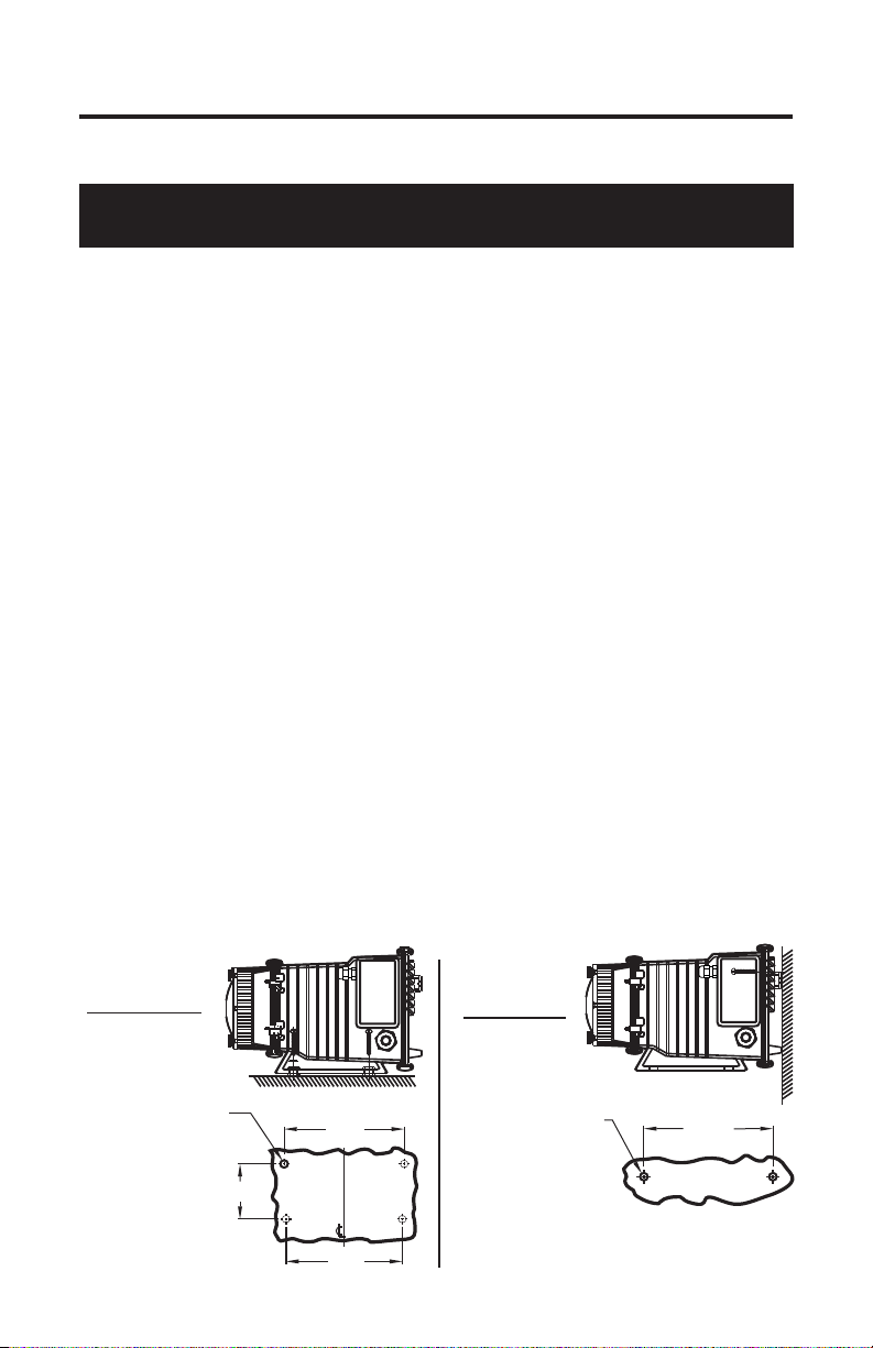
Floor Mount
Drill .156 Dia. (5/32)
For Self-Tap Screw
#10 X 1” Phillips Steel
4 Places
3-1/2”
INJECTOR MOUNTING
Wall Mount
7-5/8”
7-3/8”
Drill .156 Dia. (5/32)
For Self-Tap Screw
#10 X 1” Phillips Steel
Note: For wall-mounting, drill & thread into
solid wood only.
8-3/16”
2 Places
Page 5
A-100NE Page 5
WARNING: Risk of electric shock.
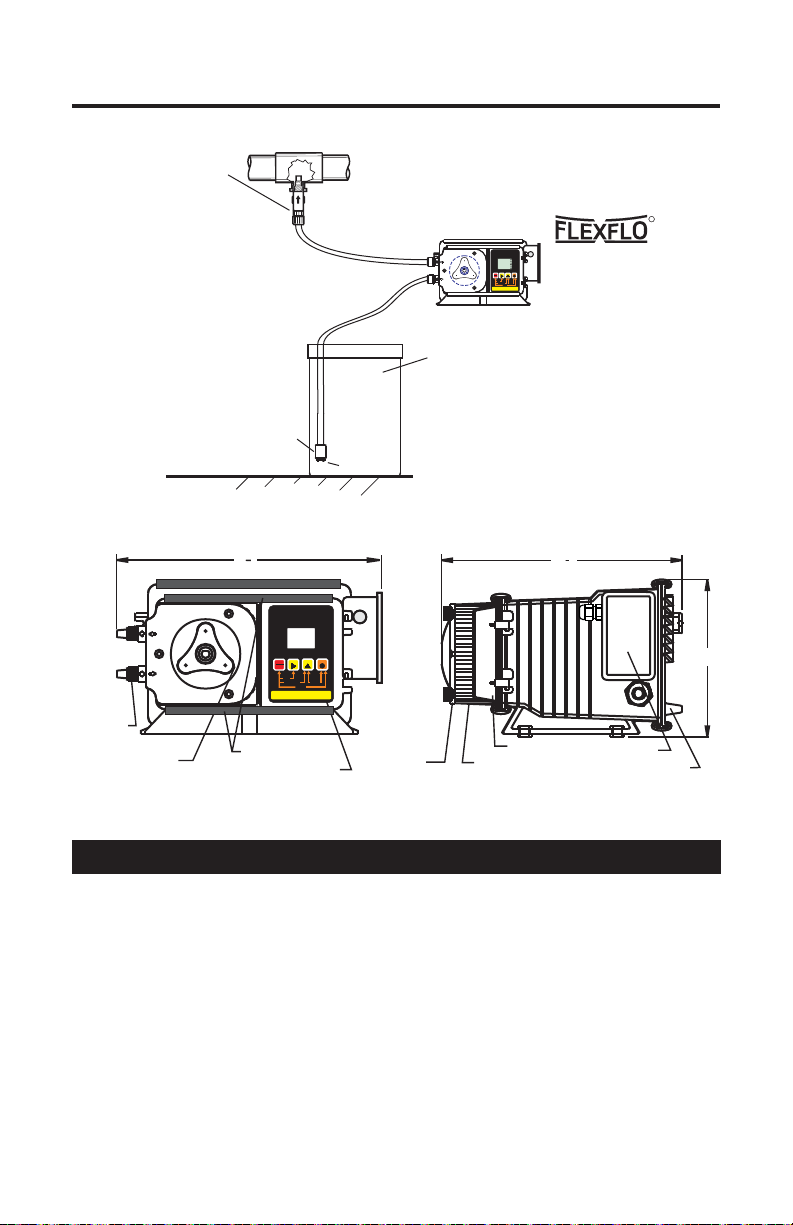
TYPICAL INSTALLATION
Injection / Check valve
with 1/4” and 1/2” male
pipe threads.
Mount in upward position
to prevent trapped gasses
in the injection fitting.
Ceramic Weight
Suction
Tube
Discharge
Tube
Strainer
Chemical
Container
with cover
RUN
STANDBY
1 - MANUAL
VARIABLE SPEED PUMP
RUN
1
MODE
PROGRAM
VDC
mA Hz
% SPEED
STAND-BY
Wall or shelf mount
PRIME
1000
MINIMUM
SERVICE
ALARM
MAXIMUM
DIGIT MODE
FIELD
away from the top of the
PRIME
DISPLAY
RESET SERVICE
PROGRAM
INPUT MODES
3 - 0-10VDC 4 - PULSE (Hz)
2 - 4-20mA
solution tank. Chemical
fumes can damage the
unit.
R
PARTS LOCATOR DRAWING
1
9
8
Control Cover
Junction Box
Rear Plate
Pumptube
Assembly
Rotor
Assembly
1
9
2
DIGITAL TIMER PUMP
FIELD
RUN
STANDBY
PRIME
RESET SERVICE
PROGRAM
INPUT MODES
2 - 4-20mA
1 - MANUAL
Slide Clamps**
Control
DIGIT MODE
DISPLAY
3 - 0-10VDC 4 - PULSE (Hz)
RUN
PROGRAM
STAND-BY
PRIME
MINIMUM
MAXIMUM
Pumphead
Cover
Pumphead
5.2 Input Power Connections
! Be certain to connect the pump to the proper supply voltage. Using the
incorrect voltage will damage the pump and may result in injury. The
voltage requirement is printed on the pump serial label.
! Removable resistors on the circuit board are factory preset for the correct
voltage. See page 7 Circuit Board Connections diagram for details.
! The pump is supplied with a ground wire conductor and a grounding type
attachment plug (power cord). To reduce the risk of electric shock, be
certain that the power cord is connected only to a properly grounded,
grounding type receptacle.
Note: When in doubt regarding your electrical installation, contact a
licensed electrician.
6.0
Page 6
A-100NEPage 6
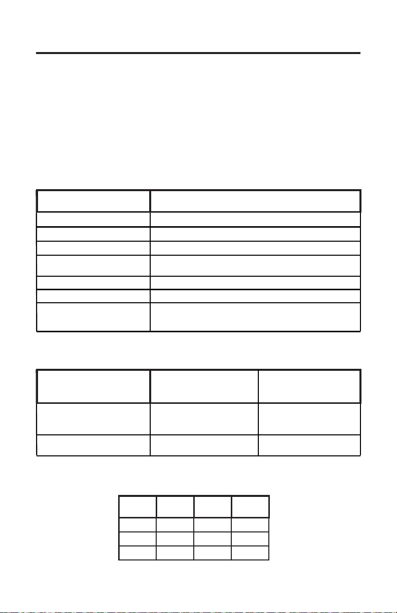
5.3 External Input Signal Connections
The pump will accept a variety of external control input signals; 4-20 mA ,
0-10 VDC, TTL, CMOS, AC Sine Waves, Contact Closures, Hall Effect,
NPN. The 4-20mA and 0-10 VDC loops must be powered.
All wiring connections are to be made inside of the junction box located on
the side of the pump. Special connectors are not required. A liquid-tite
connector is supplied and should be used for the external signal cable. The
signal input wires are color coded to the type of signal being used.
SIGNAL INPUT WIRE COLOR CODES
INPUT TYPE
WIRE COLOR CODE
4-20 mA
0-10 VDC
TTL, CMOS
CONTACT (10v @ 2 mA max)
HALL EFFECT, NPN
ALARM RELAY
FLOW VERIFICATION SENSOR
MOTOR ON SIGNAL
5-20V DC open collector output
closed while motor is energized
RED/WHITE (+ 20VDC) & BLACK (-) & YELLOW (signal)
BLUE (+) & BLACK (-)
ORANGE (+) & BLACK (-)
WHITE (+) & BLACK (-)
RED (+) & WHITE (-)
PURPLE & PURPLE
BROWN (+) & BLACK (-)
PADDLEWHEEL SENSOR SIGNAL INPUT WIRING
BLUE-WHITE
PADDLEWHEEL
SENSOR TYPE
MODEL FH
HALL EFFECT SENSOR
MODEL FC
AC SINE WAVE SENSOR
PADDLEWHEEL SENSOR
WIRE COLOR CODE
RED (+)
BLACK (-)
BARE (signal)
RED (+)
BLACK (-)
PUMP INPUT
WIRE COLOR CODE
RED (+ 20VDC)
BLACK (-)
WHITE (signal)
WHITE (+)
BLACK (-)
MOTOR LEADWIRES
HOT
INPUT
VOLTAGE
115V 60Hz
220V 50Hz
230V 60Hz
LEADWIRE
YELLOW
YELLOW
YELLOW
NEUTRAL
LEADWIRE
BLUE
BROWN
RED
GROUND
LEADWIRE
GREEN
GREEN
GREEN
Page 7
A-100NE Page 7
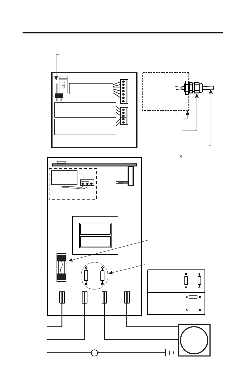
CIRCUIT BOARD CONNECTIONS
Program Disable Jumper - Located on front of Control board.
Un-installed = enable front panel programming (default)
Installed = disable front panel programming
VS = RED (+17V DC)
VS
VS
VDC = ORANGE
VDC
MA = BLUE
MA
MTR = BROWN
MTR
GND
GND = BLACK
PLS
PLS = WHITE
RELAY = PURPLE (2)
FVS+
FVS
GND
JUNCTION BOX
TFD
GND
LIQUID-TIGHT
CONNECTOR
EXTERNAL INPUT CABLE
ACCEPTABLE CABLE JACKET RANGE:
.118 - .255 INCH
.( 3,0 - 6,5 MM)
External input connections
6 Wire bundle to junction box
Flow verification sensor connector
3 Wire bundle to junction box.
red/black/yellow
Tube failure detection sensor connector
2 Wire bundle to pump head sensor
(A-100N series pumps only)
Control Circuit Board
(Back view)
COM
N/
N/C
Alarm Relay
3A/125VAC
Purple connection wires
Default is N/O
O
Power Circuit Board
(Top view)
CN3
CN4
AC
Input
Power
2A
250VAC
T4
LINE
NEUTRAL
HOT
Hot
Common
Ground (green)
LINE
RR
T1
T2
MOTOR
NEUTRAL
MOTOR
SWITCHED
Neutral (blue/brown/red)
Ground (green)
Protector Fuse
2 Amps, 250 Volt AC
(little Fuse #235002
INPUT VOLTAGE
RESISTOR PLACEMENT
115V 50/60Hz
T3
220V 50/60Hz
230V 50/60Hz
Hot (yellow)
or Equivalent)
RR
R
AC
MOTOR
Page 8
A-100NEPage 8
CAUTION: Proper eye and skin protection must be
worn when installing and servicing t
he pump.
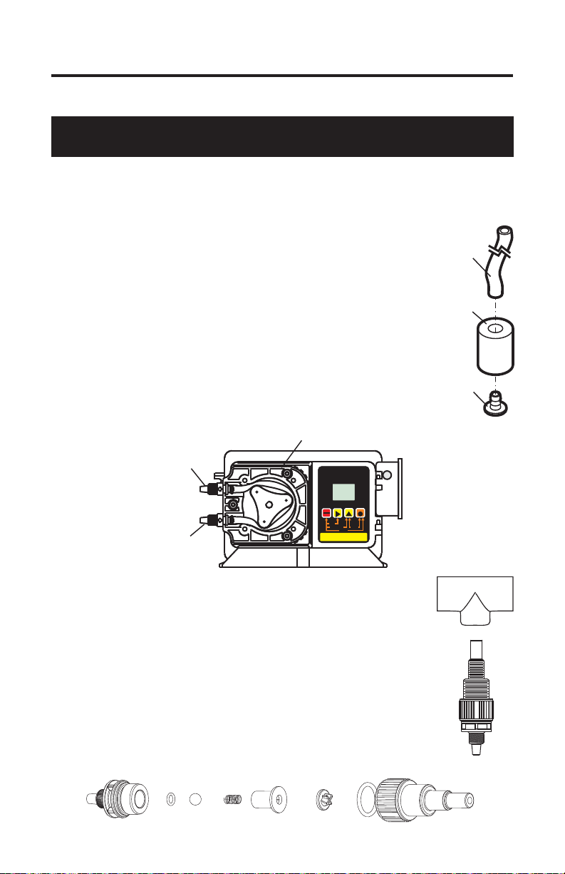
5.4 How To Install the Tubing and Fittings
! Inlet Tubing - Locate the inlet fitting of the Pump Tube. Remove the tube
nut. Push the clear PVC suction tubing onto the compression barb of the
fitting. Use the tube nut to secure the tube. Hand tighten only.
! Strainer - Trim the inlet end of the suction tubing so that
the strainer will rest approximately two inches from the
bottom of the solution tank. This will prevent sediment
from clogging the strainer. Slip the ceramic weight over the
end of the suction tube. Press the strainer into the end of
the tube. Secure the ceramic weight to the strainer. Drop
the strainer into the solution tank.
! Outlet Tubing - Locate the outlet fitting of the Pump
Tube. Remove the tube nut. Push the opaque outlet
(discharge) tubing onto the compression barb of the fitting.
Use the tube nut to secure the tube. Hand tighten only.
Keep outlet tube as short as possible.
Pump Head
Tubing
Suction 3/8"
Ceramic
Weight
Foot
Strainer
Outlet Adapter
Inlet Adapter
DIGITAL TIMER PUMP
MODE
1
1000
ON-T
TOT-TSECMINHRDAY
ALARM
TFD
FVS
FIELD
RUN
STANDBY
PRIME
RESET SERVICE
PROGRAM
INPUT MODES
2 - 4-20mA
1 - MANUAL
4 - 0-1000 Hz
mA Hz
VDC
SERVICE
5 - PULSE (BATCH)
DIGIT MODE
RUN
PROGRAM
STAND-BY
PRIME
MINIMUM
MAXIMUM
DISPLAY
3 - 0-10VDC
! Injection/Check Valve Fitting Installation - The
Injection/Check valve fitting is designed to install directly
into either 1/4” or 1/2” female pipe threads. This fitting will
require periodic cleaning, especially when injecting fluids
that calcify such as sodium hypochlorite. See section 7.0.
Install the Injection/Check valve directly into the piping
system. To prevent trapped gasses, install the fitting in an
upward direction. Use Teflon thread sealing tape on the pipe
threads.
Push the opaque outlet (discharge) tubing onto the compression barb of the Injection/Check valve fitting. Use the tube
nut to secure the tube. Hand tighten only.
Page 9
A-100NE Page 9
6.0 How to operate the pump
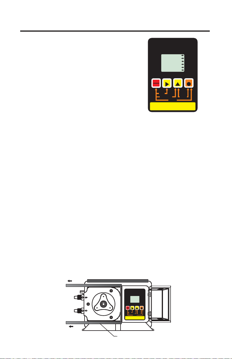
6.1 Pump Output Controls
-
Open the control panel door by sliding the
upper and lower slide clamps to the left.
! RUN/STANDBY Button -
+
Press to start and stop the pump.
The
ARROW next to the word RUN will light
when in the run mode. The ARROW next
to the word STAND-BY will blink when in
the stand-by mode.
+Press to clear ALARM.
+
When pressed with the FIELD Button, initiates a 99 second prime cycle
which temporarily overrides the mode setting and runs the pump motor at
100% speed. The ARROW next to the word PRIME will blink.
+
When pressed with the DIGIT button, resets the 500 hour service warning
timer to zero.
+
When pressed with the MODE button, initiates the programming mode.
The ARROW next to the word PROGRAM will blink.
! FIELD Button -
+In the programming mode, selects the digit to be changed.
! DIGIT Button -
+
In the programming mode, increases the selected digit.
+
When pressed with the MODE Button, toggles the display from operating
time cycle values to input signal value.
! MODE Button -
+Used to select one of five operating modes.
Mode 0 - TFD system and FVS system set-up
Mode 1 - Manual Adjustment (external input disabled)
Mode 2 - 4-20mA input
Mode 3 - 0-10VDC input
Mode 4 - Frequency input adjusts cycle on-time
Mode 5 - Pulse input count = single batch time
DIGITAL TIMER PUMP
MODE
1
VDC
mA Hz
1000
ON-T
TOT-TSEC MINHR DAY
ALARM
TFD
FVS
SERVICE
FIELD
RUN
STANDBY
PRIME
RESET SERVICE
PROGRAM
INPUT MODES
2 - 4-20mA
1 - MANUAL
4 - 0-1000 Hz
5 - PULSE (BATCH)
RUN
PROGRAM
STAND-BY
PRIME
MINIMUM
MAXIMUM
DIGIT MODE
DISPLAY
3 - 0-10VDC
DIGITAL TIMER PUMP
MODE
1
VDC
mA Hz
1000
ON-T
TOT-TSECMINHRDAY
ALARM
TFD
FVS
SERVICE
DIGIT MODE
FIELD
RUN
STANDBY
PRIME
DISPLAY
RESET SERVICE
PROGRAM
INPUT MODES
3 - 0-10VDC
2 - 4-20mA
1 - MANUAL
5 - PULSE (BATCH)
4 - 0-1000 Hz
SLIDE CLAMP
RUN
PROGRAM
STAND-BY
PRIME
MINIMUM
MAXIMUM
Page 10

A-100NEPage 10
6.2 MODE 0 - TFD and FVS system set-up
Mode 0 is used to program the TFD (Tube Failure Detection) system and
the FVS (Flow Verification System).
TFD (Tube Failure Detection) -
!
Tube Failure Detection System which is designed to stop the pump and
provide a contact closure output in the event the pump tube should rupture
and chemical enters the pump head. This patented system is capable of
detecting the presence of a large number of chemicals including Sodium
Hypochlorite (Chlorine), Hydrochloric
(muriatic) Acid, Sodium Hydroxide, and
many others. The system will not be
triggered by water (rain, condensation, etc.)
or silicone oil (roller and tubing lubricant).
If the system has detected chemical, the
pump tube must be replaced and the pump
head and roller assembly must be
thoroughly cleaned.
Confirm Chemical Detection - To determine if your chemical will be
detected by the system, remove the pump tube and roller assembly. Place a
small amount of the chemical in the bottom of the pump head - just enough
to cover the sensors. Turn on the pump. If the TFD system detects the
chemical, the pump will stop after a five second confirmation period and
the ALARM icon will light on the display. If the TFD system does not
detect the chemical, the pump will continue to run after the confirmation
period. Carefully clean the chemical out of the pump head being sure to
remove all traces of chemical from the sensor probes. Press the
RUN/STAND-BY button to clear the alarm condition and restart the pump.
Contact Closure Alarm Output - A contact closure output (relay) is
provided with the TFD system. The relay can be configured for normally
open (factory default) or normally closed operation by properly positioning
the connector plug on the circuit board (see page 7).
The A-100NE is equipped with a
Tubing failure
Chemical
This Shroud is designed to weather proof this Peristaltic Pump. If the
pump is wall mounted the shroud is not necessary and will still be
considered weather proof.
Floor Mount
Shroud
Weather proof
Wall Mount
Weather proof
Page 11

A-100NE Page 11
OPERATING
FLOW RANGE
(ml/min)
(FVS) Flow Verification System The A-100NE is equipped with a
!
-
Flow Verification System which is designed to stop the pump and provide a
contact closure output in the event the sensor does not detect chemical
during pump operation. This could indicate a clogged injection fitting,
empty chemical solution tank, worn pump tube, loose tubing connection,
etc.
To allow the pump to clear any gasses that may have accumulated during
stopper operation (such as with chlorine), an alarm delay time value from 1256 seconds must be programmed (An alarm delay value of 000 seconds
disables the FVS system). The pump will stop, and the alarm mode
activated, if no pulses are received by the pump and the alarm delay time
period has ended. Press the STAND-BY button twice to clear the alarm and
restart the pump. The Flow Verification Sensor is sold as an optional
accessory.
Confirm the FVS flow range - The Flow
Verification Sensor (FVS) will only function
within its operating range. Sensor model FV100-6V has an operating range of 30-300
ml/min (1-10 oz/min). If the pump’s output is
less than 30 ml/min (0.5 ml/sec), the sensor
will not detect chemical and a signal will not
be sent to the pump.
SENSOR
MODEL
NUMBER
FV-100-6V
FV-200-6V
FV-300-6V
FV-400-6V
FV-500-6V
FV-600-6V
30-300
100-1000
200-2000
300-3000
500-5000
700-7000
Install the FVS Flow Sensor - The Flow Verification Sensor (FVS) should
be installed on the inlet (suction) side of the pump tube. The sensor includes
a PVC tubing insert, located inside the sensor’s female thread connection,
that is designed to seal the sensor onto the pump tube inlet adapter. Thread
the sensor onto the pump tube until the tubing insert is snug against the
pump tube inlet fitting - do not over-tighten.
Connect the red/white, black, and white wires from the sensor to the red,
black, and yellow wires located in the pump’s junction box. See page 7.
Outlet Adapter
DIGITAL TIMER PUMP
RUN
MODE
1
PROGRAM
VDC
mA Hz
FVS Sensor
STAND-BY
PRIME
1000
MINIMUM
ON-T
TOT-TSECMINHR DAY
ALARM
TFD
FVS
SERVICE
MAXIMUM
DIGIT MODE
FIELD
RUN
STANDBY
PRIME
DISPLAY
RESET SERVICE
PROGRAM
INPUT MODES
3 - 0-10VDC
2 - 4-20mA
1 - MANUAL
4 - 0-1000 Hz
5 - PULSE (BATCH)
Inlet Adapter
Contact Closure Alarm Output - A contact closure output (relay) is
provided with the FVS system. The relay can be configured for normally
open (factory default) or normally closed operation by properly positioning
the connector plug on the circuit board (see page 7).
Page 12

A-100NEPage 12
! Enable and Program the TFD and FVS Systems
The TFD and FVS systems must be enabled.
+Set the pump for mode 0. Press the MODE button until MODE 0 is
shown on the LCD display.
+Enter the programming mode. At the same
time, press the RUN/STANDBY button and
the MODE button. A blinking ARROW will
point to the word PROGRAM indicating the
program mode has been activated. The TFD
icon will blink. The word ON will display
indicating the TFD system is activated.
+Press the DIGIT button to toggle the system
on and off.
+Press the MODE button to enter the FVS
system programming. The FVS icon will
blink. The display will indicate the current
alarm delay time setting in seconds. (000 =
OFF.
+Press the DIGIT button to set the number of seconds of alarm delay time.
The number will increase to a maximum of 256 seconds and roll over to
OFF.
+To exit the programming mode, press the RUN/STANDBY button and the
MODE button at the same time. The arrow next to the word PROGRAM
will disappear and an arrow will appear next to the word RUN.
MODE
MODE
TFD
0
0
On
FVS
001
SEC
RUN
PROGRAM
STAND-BY
PRIME
MINIMUM
MAXIMUM
RUN
PROGRAM
STAND-BY
PRIME
MINIMUM
MAXIMUM
NOTE: If while in the program mode no buttons are pressed within 60
seconds, the circuitry will automatically return to the run mode.
6.3 Mode 1 - Manually adjusting the output - In this mode, the pump
is turned on and off by an electronic cycle timer. The pump will energize for
the duration of the “on time” and de-energize for the remainder of the “total
time” thus completing one cycle. The cycle then repeats.
The “on time” and “total time” cycles are independently adjustable from 0.1
to 199.9 units of measure with a 0.1 unit resolution. The units of measure
can be seconds, minutes, hours or days.
Example: If the “total time” cycle is adjusted for 90 seconds and the “on
time” portion of the cycle is adjusted for 5 seconds, the pump will run for 5
seconds and turn off for 85 seconds (90 second total cycle). This cycle is
repeated until either the standby button is pressed, the cycle time is changed
or the input power is disconnected from the pump.
+Set the pump for mode 1. Press the MODE button until MODE 1 is
shown on the LCD display.
Page 13

A-100NE Page 13
+Enter the programming mode. At the same
time, press the RUN/STANDBY button and
the MODE button. A blinking ARROW will
point to the word PROGRAM indicating the
program mode has been activated. The total
MODE
1
199.9
TOT-T SEC
time TOT-T icon will blink. The currently
selected time unit icon will be displayed. The current total time setting
will be displayed and the left most (selected) digit will blink. The decimal
is fixed and cannot be moved.
+Pressing the DIGIT button will increase the selected digit.
+Pressing the FIELD button will select a new the digit to the right or the
time unit.
+Press the DIGIT button to increase the selected digit or time unit.
RUN
PROGRAM
STAND-BY
PRIME
MINIMUM
MAXIMUM
+Press the MODE button to exit the total
time programming screen and enter the on
time programming screen. The ON-T icon
will blink. The currently selected time unit
icon will be displayed. The current on time
setting will be displayed and the left most
MODE
1
42.5
ON-T
SEC
RUN
PROGRAM
STAND-BY
PRIME
MINIMUM
MAXIMUM
(selected) digit will blink.
+Pressing the DIGIT button will increase the selected digit.
+Pressing the FIELD button will select a new the digit to the right or the
time unit.
+Press the DIGIT button to increase the selected digit or time unit.
+At the same time, press the RUN/STANDBY button and the MODE
button. A blinking ARROW will point to the word RUN indicating the run
mode has been activated.
NOTE: If while in the program mode no buttons are pressed within 60
seconds, the circuitry will automatically return to the run mode.
Page 14

A-100NEPage 14
6.4 Mode 2 - 4-20 mA input - In this mode, the on-time of the cycle will
automatically adjust to match the received mA input value. When the mA
input value is equal the programmed maximum, the pump will run
continuously.
Four values must be programmed:
1) ON-T = The amount of time the pump will run, per cycle, when the
minimum mA value is received. (Typically programmed to zero)
2) mA minimum = The mA input value that will result in the on time (ON-
T). (Typically programmed to 4 mA)
3) TOT-T = The total cycle time.
4) mA maximum = The mA input value that will result in the pump running
continuously.
8
Example:
ON-T setting = 0 seconds
mA minimum setting = 4mA
TOT-T setting = 8 seconds
mA maximum setting = 14.8mA
6
4
2
Pump Run-Time (Sec.)
0
6
8
4
10
12
14
16
18
20
Milliamp input (mA)
+Set the pump for mode 2. Press the
MODE button until MODE 2 is shown on
the LCD display.
+Enter the programming mode. At the
same time, press the RUN/STANDBY
button and the MODE button. A blinking
ARROW will point to the word PROGRAM
indicating the program mode has been
MODE
2
00.0
ON-T
SEC
RUN
PROGRAM
STAND-BY
PRIME
MINIMUM
MAXIMUM
activated. The on time ON-T icon will
blink. The currently selected time unit
icon will be displayed. The current on time setting will be displayed and
the left most (selected) digit will blink. The decimal is fixed and cannot be
moved.
+Pressing the DIGIT button will increase the selected digit.
+Pressing the FIELD button will select a new the digit to the right or the
time unit.
+Press the DIGIT button to increase the selected digit or time unit.
Page 15

A-100NE Page 15
+Press the MODE button to exit the on time
programming screen and enter the mA
minimum programming screen. The mA
icon will blink. A blinking ARROW will
MODE
2
04.0
mA
appear next to the word MINIMUM. The
current minimum mA setting will be
displayed and the left most (selected) digit
will blink.
+Pressing the DIGIT button will increase the selected digit.
+Pressing the FIELD button will select a new the digit to the right.
+Press the DIGIT button to increase the selected digit.
+Press the MODE button to exit the mA
minimum programming screen and enter
the total time programming screen. The
total time TOT-T icon will blink. The
currently selected time unit icon will be
MODE
2
00.0
SEC
TOT-T
displayed. The current total time setting
will be displayed and the left most
(selected) digit will blink. The decimal is fixed and cannot be moved.
+Pressing the DIGIT button will increase the selected digit.
+Pressing the FIELD button will select a new the digit to the right or the
time unit.
+Press the DIGIT button to increase the selected digit or time unit.
+Press the MODE button to exit the total time programming screen and
enter the mA maximum programming
screen. The mA icon will blink. A blinking
ARROW will appear next to the word
MAXIMUM. The current maximum mA
MODE
2
20.0
mA
setting will be displayed and the left most
(selected) digit will blink.
+Pressing the DIGIT button will increase
the selected digit.
+Pressing the FIELD button will select a new the digit to the right.
+Press the DIGIT button to increase the selected digit.
+At the same time, press the RUN/STANDBY button and the MODE
button. A blinking ARROW will point to the word RUN indicating the run
mode has been activated.
RUN
PROGRAM
STAND-BY
PRIME
MINIMUM
MAXIMUM
RUN
PROGRAM
STAND-BY
PRIME
MINIMUM
MAXIMUM
RUN
PROGRAM
STAND-BY
PRIME
MINIMUM
MAXIMUM
NOTE: If while in the program mode no buttons are pressed within 60
seconds, the circuitry will automatically return to the run mode.
Page 16

A-100NEPage 16
6.5 Mode 3 - 0-10V DC input - In this mode, the on-time of the cycle
will automatically adjust to match the received VDC input value. When the
VDC value is equal the programmed maximum, the pump will run
continuously.
Four values must be programmed:
1) ON-T = The amount of time the pump will run, per cycle, when the
minimum VDC value is received. (Typically programmed to zero)
2) VDC minimum = The VDC input value that will result in the on time
(ON-T). (Typically programmed to 0 VDC)
3) TOT-T = The total cycle time.
4) VDC maximum = The VDC input value that will result in the pump
running continuously.
6.0
Example:
ON-T setting = 0 seconds
VDC minimum setting = 0 VDC
TOT-T setting = 6 seconds
VDC
maximum setting = 7.5 VDC
4.5
3.0
1.5
Pump Run-Time (Sec.)
0
3
2
0
1
4
7
9
5
6
10
8
DC voltage input (VDC)
+Set the pump for mode 3. Press the
MODE button until MODE 3 is shown on
the LCD display.
+Enter the programming mode. At the
same time, press the RUN/STANDBY
button and the MODE button. A blinking
ARROW will point to the word PROGRAM
indicating the program mode has been
MODE
3
00.0
ON-T
SEC
RUN
PROGRAM
STAND-BY
PRIME
MINIMUM
MAXIMUM
activated. The on time ON-T icon will
blink. The currently selected time unit
icon will be displayed. The current on time setting will be displayed and
the left most (selected) digit will blink. The decimal is fixed and cannot be
moved.
+Pressing the DIGIT button will increase the selected digit.
+Pressing the FIELD button will select a new the digit to the right or the
time unit.
+Press the DIGIT button to increase the selected digit or time unit.
Page 17

A-100NE Page 17
+Press the MODE button to exit the on time
programming screen and enter the
minimum programming screen. The VDC
icon will blink. A blinking ARROW will
VDC
MODE
3
0.0
appear next to the word MINIMUM. The
current minimum VDC setting will be
displayed and the left most (selected) digit
will blink.
+Pressing the DIGIT button will increase the selected digit.
+Pressing the FIELD button will select a new the digit to the right.
+Press the DIGIT button to increase the selected digit.
+Press the MODE button to exit the VDC
minimum programming screen and enter
MODE
3
the total time programming screen. The
total time TOT-T icon will blink. The
currently selected time unit icon will be
00.0
SEC
TOT-T
displayed. The current total time setting
will be displayed and the left most
(selected) digit will blink. The decimal is fixed and cannot be moved.
+Pressing the DIGIT button will increase the selected digit.
+Pressing the FIELD button will select a new the digit to the right or the
time unit.
+Press the DIGIT button to increase the selected digit or time unit.
+Press the MODE button to exit the total time programming screen and
enter the VDC maximum programming
screen. The VDC icon will blink. A
blinking ARROW will appear next to the
word MAXIMUM. The current maximum
MODE
3
9.5
VDC setting will be displayed and the left
most (selected) digit will blink.
+Pressing the DIGIT button will increase
the selected digit.
+Pressing the FIELD button will select a new the digit to the right.
+Press the DIGIT button to increase the selected digit.
+At the same time, press the RUN/STANDBY button and the MODE
button. A blinking ARROW will point to the word RUN indicating the run
mode has been activated.
VDC
VDC
RUN
PROGRAM
STAND-BY
PRIME
MINIMUM
MAXIMUM
RUN
PROGRAM
STAND-BY
PRIME
MINIMUM
MAXIMUM
RUN
PROGRAM
STAND-BY
PRIME
MINIMUM
MAXIMUM
NOTE: If while in the program mode no buttons are pressed within 60
seconds, the circuitry will automatically return to the run mode.
Page 18

A-100NEPage 18
6.6 Mode 4 - Frequency (Hz) input - In this mode, the on-time of the
cycle will automatically adjust to match the received Hz input value. When
the Hz value is equal the programmed maximum, the pump will run
continuously.
Four values must be programmed:
1) ON-T = The amount of time the pump will run, per cycle, when the
minimum hZ value is received. (Typically programmed to zero)
2) Hz minimum = The Hz input value that will result in the on time (ON-
T). (Typically programmed to 0 Hz)
3) TOT-T = The total cycle time.
4) Hz maximum = The Hz input value that will result in the pump running
continuously.
8
7
Example:
ON-T setting = 0 seconds
Hz minimum setting = 0 Hz
TOT-T setting = 8 seconds
Hz
maximum setting = 425 Hz
6
5
4
3
2
1
Pump Run-Time (Sec.)
0
3
2
0
1
4
Frequency input (x100)
7
9
5
6
10
8
+Set the pump for mode 4. Press the
MODE button until MODE 4 is shown on
the LCD display.
+Enter the programming mode. At the
same time, press the RUN/STANDBY
button and the MODE button. A blinking
ARROW will point to the word PROGRAM
indicating the program mode has been
MODE
4
00.0
ON-T
SEC
RUN
PROGRAM
STAND-BY
PRIME
MINIMUM
MAXIMUM
activated. The on time ON-T icon will
blink. The currently selected time unit
icon will be displayed. The current on time setting will be displayed and
the left most (selected) digit will blink. The decimal is fixed and cannot
be moved.
+Pressing the DIGIT button will increase the selected digit.
+Pressing the FIELD button will select a new the digit to the right or the
time unit.
+Press the DIGIT button to increase the selected digit or time unit.
Page 19

A-100NE Page 19
+Press the MODE button to exit the on time
programming screen and enter the Hz
minimum programming screen. The HZ
icon will blink. A blinking ARROW will
MODE
4
000
appear next to the word MINIMUM. The
current minimum Hz setting will be
displayed and the left most (selected) digit
will blink.
+Pressing the DIGIT button will increase the selected digit.
+Pressing the FIELD button will select a new the digit to the right.
+Press the DIGIT button to increase the selected digit.
+Press the MODE button to exit the Hz
minimum programming screen and enter
MODE
4
the total time programming screen. The
total time TOT-T icon will blink. The
currently selected time unit icon will be
08.0
SEC
TOT-T
displayed. The current total time setting
will be displayed and the left most
(selected) digit will blink. The decimal is fixed and cannot be moved.
+Pressing the DIGIT button will increase the selected digit.
+Pressing the FIELD button will select a new the digit to the right or the
time unit.
+Press the DIGIT button to increase the selected digit or time unit.
+Press the MODE button to exit the total time programming screen and
enter the Hz maximum programming
screen. The HZ icon will blink. A blinking
ARROW will appear next to the word
MAXIMUM. The current maximum Hz
MODE
4
425
setting will be displayed and the left most
(selected) digit will blink.
+Pressing the DIGIT button will increase
the selected digit.
+Pressing the FIELD button will select a new the digit to the right.
+Press the DIGIT button to increase the selected digit.
+At the same time, press the RUN/STANDBY button and the MODE
button. A blinking ARROW will point to the word RUN indicating the run
mode has been activated.
RUN
Hz
PROGRAM
STAND-BY
PRIME
MINIMUM
MAXIMUM
RUN
PROGRAM
STAND-BY
PRIME
MINIMUM
MAXIMUM
RUN
Hz
PROGRAM
STAND-BY
PRIME
MINIMUM
MAXIMUM
NOTE: If while in the program mode no buttons are pressed within 60
seconds, the circuitry will automatically return to the run mode.
Page 20

A-100NEPage 20
6.7 Mode 5 - Pulse input (Batch) - In this mode, when the total number
of accumulated pulses is equal to the programmed pulse input value (Hz) ,
the pump will run for the programmed on time.
Two values must be programmed:
1) ON-T = The amount of time the pump will run when accumulated pulses
is equal to the programmed pulse input value (Hz).
2) Hz maximum = The number of input pulses that will trigger the batch.
+Set the pump for mode 5. Press the MODE button until MODE 5 is
shown on the LCD display.
+Enter the programming mode. At the
same time, press the RUN/STANDBY
MODE
5
button and the MODE button. A blinking
ARROW will point to the word PROGRAM
indicating the program mode has been
00.0
ON-T
SEC
activated. The on time ON-T icon will
blink. The currently selected time unit
icon will be displayed. The current on time setting will be displayed and
the left most (selected) digit will blink. The decimal is fixed and cannot be
moved.
+Pressing the DIGIT button will increase the selected digit.
+Pressing the FIELD button will select a new the digit to the right or the
time unit.
+Press the DIGIT button to increase the selected digit or time unit.
+Press the MODE button to exit the on time
programming screen and enter the Hz
MODE
5
(pulses per batch) programming screen.
The HZ icon will blink. A blinking ARROW
000
will appear next to the word MAXIMUM.
The current Hz setting will be displayed
and the left most (selected) digit will
blink.
+Pressing the DIGIT button will increase the selected digit.
+Pressing the FIELD button will select a new the digit to the right.
+Press the DIGIT button to increase the selected digit.
+At the same time, press the RUN/STANDBY button and the MODE
button. A blinking ARROW will point to the word RUN indicating the run
mode has been activated.
RUN
PROGRAM
STAND-BY
PRIME
MINIMUM
MAXIMUM
RUN
Hz
PROGRAM
STAND-BY
PRIME
MINIMUM
MAXIMUM
NOTE: If while in the program mode no buttons are pressed within 60
seconds, the circuitry will automatically return to the run mode.
Page 21

A-100NE Page 21
CAUTION: Proper eye and skin protection must be
worn when installing and servicing t
he pump.
7.0 How to Maintain the A-100NE
7.1 Routine Inspection and Maintenance
The A-100NE requires very little maintenance. However, the pump and all
accessories should be checked weekly. This is especially important when
pumping chemicals. Inspect all components for signs of leaking, swelling,
cracking, discoloration or corrosion. Replace worn or damaged components immediately.
Cracking, crazing, discoloration and the like during the first week of
operation are signs of severe chemical attack. If this occurs, immediately
remove the chemical from the pump. Determine which parts are being
attacked and replace them with parts that have been manufactured using
more suitable materials. The manufacturer does not assume responsibility
for damage to the pump that has been caused by chemical attack.
7.2 How to Clean and Lubricate the A-100NE
The A-100NE will require occasional cleaning and lubricating. The amount
will depend on the severity of service.
]
When changing the pump tube assembly, the pump head chamber, roller
assembly and pump head cover should be wiped free of any dirt and debris.
]
The pump head cover bearing may require grease periodically. Apply a
small amount of grease (Aeroshell aviation grease #5 or equivalent) when
necessary.
]
Although not necessary, 100% silicon lubrication may be used on the
roller assembly and tube assembly.
]
Periodically clean the injection/check valve assembly, especially when
injecting fluids that calcify such as sodium hypochlorite. These lime
deposits and other build ups can clog the fitting, increase the back pressure
and interfere with the check valve operation.
]
Periodically clean the suction strainer.
]
Periodically inspect the air vents located under the motor compartment
and on the rear panel. Clean if necessary.
7.3 500 Hour Service Warning Timer
The A-100NE is equipped with a tube life warning timer. After approximately 500 hours of accumulated running time, the SERVICE icon will light.
This is a reminder that the pump tube is nearing its minimum life expectancy and should be replaced. Your actual tube life will depend on many
factors such as the chemical used, back pressure, temperature, viscosity,
and motor RPM.
Page 22

A-100NEPage 22
7.4 How to Replace the Pump Tube
The pump tube assembly will eventually break if not replaced. The tube has
been designed for a minimum service life of 500 hours. However, the life
of the tube is affected by many factors such as the type of chemical being
pumped, the amount of back pressure, the motor RPM, temperature and
others. The pump tube assembly must be inspected and replaced regularly.
After replacing the pump tube, press the Stand-by button and the Digit
button at the same time to reset the tube life warning timer.
Remove the Old Pump Tube - The pump roller assembly spins in a
counter clockwise direction. The pump head inlet (suction) side is located
at the bottom of the pump and the outlet (discharge) is located at the top of
the pump head.
+Release any pressure that may be in
the discharge tubing.
Outlet Adapter
+Disconnect the suction and discharge
tubes from the pump tube.
+Remove the pump head cover.
+With the pump running, pull the inlet
fitting out of the pumphead. Guide the
tube counter clockwise away from the
rollers. Pull the outlet fitting out of the
Inlet Adapter
pump head.
Install the New Pump Tube - Be sure the pump head chamber is clean and
free of any debris.
Remove and inspect the roller assembly. Be sure the rollers spin freely. If
required, apply a small amount of grease to the pump head cover bearing.
+With the pump running, insert the inlet (suction) side of the Pump Tube
fitting into the pump head.
+Carefully guide the Pump Tube into the pump head. Stretch the tube
slightly and insert the outlet (discharge) fitting into the upper retaining slot
in the pump head.
+Place the clear cover on the pump head and secure with three screws.
Pump Head
DIGITAL TIMER PUMP
MODE
1
ON-T
TFD
FIELD
RUN
STANDBY
PRIME
RESET SERVICE
1 - MANUAL
4 - 0-1000 Hz
1000
TOT-TSECMINHRDAY
ALARM
FVS
INPUT MODES
mA Hz
SERVICE
PROGRAM
2 - 4-20mA
5 - PULSE (BATCH)
VDC
DIGIT MODE
RUN
PROGRAM
STAND-BY
PRIME
MINIMUM
MAXIMUM
DISPLAY
3 - 0-10VDC
Page 23

A-100NE Page 23
THIS PAGE BLANK
Page 24

A-100NEPage 24
REPLACEMENT PARTS DRAWING
4
5
1
18
19
21
20
2
3
54
53
55
7
52
9
8
56
10
17
33
OPTIONAL
QUICKCONNECT
35
22
23
25
24
26
27
6
50
2
51
E
)
L
D
0
)
T
C
E
I
0
1
Y
L
S
T
1
C
K
X
R
N
(
N
L
X
T
E
E
T
T
(
IN
E
E
U
S
E
A
X
V
H
L
N
U
U
N
E
U
T
I
M
S
M
W
A
N
N
B
I
W
I
J
P
P
I
S
O
L
O
M
T
T
D
M
L
Y
E
N
N
U
O
T
C
I
I
A
A
U
P
D
L
M
D
V
0
N
R
E
L
0
E
O
D
1
I
M
-
I
- S
T
T
5
6
7
P
P
C
P
MO
G
T
N
E
I
E
L
R
)
S
P
A
E
FF
E
W
S
U
O
L
D
R
E
H
L
A
T
F
E
C
E
A
TE
I
M
U
L
L
R
M
D
E
P
E
B
E
N
OR
I
O
YC
V
E
(
U
B
OR
N
C
N
T
L
.
U
N
I
M
M
C
T
A
C
I
D
A
A
D
Y
U
E
T
N
m
m
V
R
N
S
B
E
0
4
0
U
-
A
P
2
1
9
D
M
0
-
P
9
M
4
2
0
N
M
-
-
-
-
N
O
A
I
1
2
3
4
T
C
P
P
P
P
E
S
R
12
14
3
P
P
T
S
I
OW
S
D
A
F
N
-
E
H
W
E
G
N
A
11
28
29
32
30
31
40
36
13
15
16
46
34
37
49
39
38
45
48
Page 25

A-100NE Page 25
REPLACEMENT PARTS LIST
71000-467 Stator 45, 60RPM, 220v Brn-White/yell 1
Item Part No Description Qty
71000-468 Stator 45, 60RPM, 230v Red-White/Yell 1
22 71000-466 Stator 45, 60RPM, 115v Blu-White/Yell 1
23 90011-024 Screw, Green Ground, 8-32 x .25 1
A-008-2 Gearbox, 30 Rpm 1
A-008-3 Gearbox, 45 Rpm 1
A-008-4 Gearbox, 60 Rpm 1
71000-488 Pumphead, w/TFD sensors 1
24 90011-078 Washer, Ground Screw, #8 Star 1
25 90010-222 Wire, Motor ground, Digital Timers, Green 1
26 A-008-1 Gearbox, 14 Rpm 1
27 76001-009 Pumphead, no TFD sensors 1
A-002N-6T Pump Tube, .37 O.D., Compression Barb 1
A-002N-7T Pump Tube, .43 O.D., Compression Barb 1
A-002N-6Q Pump Tube, .37 O.D., Quick-connect 1
28 C-324N Screw, 10-32 X .50 Phil Pan Black 4
29 A-031 Spacer, Rotor 1
30 A-002N-4T Pump Tube, .25 O.D., Compression Barb 1
31 C-330-6 Nut, Tube Compress Type, .37 O.D. Tubing 2
32 A-002N-4Q Pump Tube, .25 O.D., Quick-connect 1
33 90003-007 O-ring, Quick-connect Pump Tubes, Viton 2
34 90008-299 Adapter, Quick-connect In, .37 O.D. Tube 1
35 90008-300 Adapter, Quick-connect Out, .37 O.D. Tube 1
36 C-335-6 Tubing, Outlet, .37 O.D. X 5ft, Polyethylene 1
37 C-334-6 Tubing, Inlet, .37 O.D. X 5ft, Clear PVC 1
71000-350 Roller Assembly -7 tubes (black rollers) 1
38 C-346 Weight, Inlet Tubing, Ceramic 1
39 C-342-2 Strainer, Inlet Tube, Polypropylene 1
40 71000-159 Roller Assembly -4, -6 tubes (white rollers) 1
45 71000-156 Cover, Pumphead With Sleeve Bearing 1
46 76001-003 Bearing, Sleeve, Pumphead Cover 1
90006-601 Motor Clip, 45RPM & 60RPM, SS 1
48 90011-160 Screw, Pumphead Cover, 8-32 X .62 Cap 3
49 A-014N-6A Inj Valve Assy, .5-.25 MPT X .37OD Tube 1
50 90006-583 Motor Clip, 14RPM & 30RPM, SS 1
51 90011-146 Screw, Motor Clip, 8-32X.25 Phil, SS 1
52 90007-515 Bushing, Junction Box Connector, Alum. 1
53 76001-168 Junction Box A-100N Ext. Input, Valox 1
54 90011-129 Screw, Cover, 6-32X.25 Phil Pan SS Black 2
55 71000-133 Cover, Junction Box with Gasket and Label 1
56 90008-199 Connector Liquid-tight 1
A-023N-E-220 Timer 220V w/ external control 1
A-023N-E-230 Timer 230V w/ external control 1
71000-176 Power Cord, 220v50hz, Digital Models 1
71000-177 Power Cord, 230v60hz, Digital Models 1
1 71000-214 Enclosure Back Plate With Gasket, Valox 1
Item Part No Description Qty
2 90011-094 Washer, Mounting, #10 Stainless 2
3 90011-091 Mounting Screw, #10 X 1.0” Phillips Steel 4
4 76001-001 Tubing Spacer A-100N digital 2
5 90010-036 Wire Nut, Blue 1
6 90006-580 Gasket, Enclosure Back Plate 1
7 A-023N-E-115 Timer 115V w/ external control 1
8 90010-223 Fuse, Digital Timer, 2A 250VAC 1
9 71000-175 Power Cord, 115v60hz, Digital Models 1
10 70000-589 Cord Inlet Bushing 1
11 90003-559 Mounting Feet, Rubber 4
12 76001-000 Slide Clamp, Enclosure Rear 1
13 76000-999 Slide Clamp, Enclosure Front 1
14 76001-169 Enclosure A-100N Ext. Input 1
70002-147 Gearmotor, 30 Rpm, 115v60hz 1
70002-156 Gearmotor, 45 Rpm, 115v60hz 1
70002-159 Gearmotor, 60 Rpm, 115v60hz 1
70002-148 Gearmotor, 14 Rpm, 220v50hz 1
70002-149 Gearmotor, 30 Rpm, 220v50hz 1
70002-157 Gearmotor, 45 Rpm, 220v50hz 1
70002-160 Gearmotor, 60 Rpm, 220v50hz 1
70002-150 Gearmotor, 14 Rpm, 230v60hz 1
70002-151 Gearmotor, 30 Rpm, 230v60hz 1
70002-158 Gearmotor, 45 Rpm, 230v60hz 1
70002-161 Gearmotor, 60 Rpm, 230v60hz 1
15 90006-579 Gasket, Enclosure Front 1
16 90002-191 Door, Electronic Controls Cover 1
17 70002-146 Gearmotor, 14 Rpm, 115v60hz 1
C-616PN-32 Rotor 45RPM, 60RPM With Spacers 1
C-321-32 Screw, Motor, 45RPM, 60RPM Phil ST 2
71000-213 Stator 14, 30RPM, 220v Brn-White/yell 1
71000-212 Stator 14, 30RPM, 230v Red-White/Yellw 1
18 90006-581 Fan, Motor, 2.25” Diameter, Aluminum 1
19 C-612PB Bearing Bracket With Bearing 2
20 C-616PN Rotor 14RPM, 30RPM With Spacers 1
21 C-625 Screw, Motor, 14RPM, 30RPM Phil ST 2
22 71000-211 Stator 14, 30RPM, 115v Blu-White/Yell 1
Page 26

A-100NEPage 26
LIMITED WARRANTY
Your new pump is a quality product and is warranted to be free of defects as set
down in this policy. All parts, including rubberized goods, and labor are covered
under warranty for 90 days from the date of purchase. Used peristaltic pump
tube assemblies are not warranted. Parts, excluding rubberized goods, are
covered under warranty for 12 months from the date of purchase.
Warranty coverage does not include damage to the pump that results from
misuse, carelessness, abuse or alteration. Only the repair or the replacement of
the pump is covered. Blue-White Industries does not assume responsibility for
any other loss or damage.
Warranty status is determined by the pump’s serial label and the sales invoice or
receipt. The serial label must be on the pump and the pump must be
accompanied by the sales invoice or receipt to obtain warranty coverage. The
warranty status of the pump will be verified by Blue-White or a factory
authorized service center.
Please be advised; injection and metering devices are not intended as a means of
treating water to render it suitable for human consumption. When used as
hypochlorinators, they are meant to destroy bacteria and algae contamination,
before it’s removal by filtration. Acid and soda injectors are used for PH control
(balance). Blue-White injectors are factory tested with water only for pressure
and performance. Installers and operators of these devices must be well
informed and aware of the precautions to be taken when injecting various
chemicals -especially those considered hazardous or dangerous.
Should it become necessary to return an injector for repair or service, you must
attach information regarding the chemical used as some residue may be present
within the unit which could be a hazard to service personnel.
Blue-White Industries will not be liable for any damage that may result by the
use of chemicals with their injectors and it’s components. Thank you.
PROCEDURE FOR IN WARRANTY REPAIR
Carefully pack the pump to be repaired, include the foot strainer and
injection/check valve fitting. Enclose a brief description of the problem as well
as the original invoice or sales receipt showing the date of purchase. The receipt
will be returned with the unit. Prepay all shipping costs. COD shipments will
not be accepted. Warranty service must be performed by the factory or an
authorized service center. Damage caused by improper packaging is the
responsibility of the sender.
Users of electrical and electronic equipment (EEE) with the WEEE marking per Annex
IV of the WEEE Directive must not dispose of end of life EEE as unsorted municipal
waste, but use the collection framework available to them for the return, recycle,
recovery of WEEE and minimize any potential effects of EEE on the environment and
human health due to the presence of hazardous substances. The WEEE marking
applies only to countries within the European Union (EU) and Norway. Appliances are
labeled in accordance with European Directive 2002/96/EC.
Contact your local waste recovery agency for a Designated Collection Facility in your
area.
Page 27

A-100NE Page 27
AUTHORIZED SERVICE CENTERS
ARKANSAS Rice Pump & Motor NORTH CAROLINA
BT Environmental, Inc Repair Southern Industrial
Bill Thomason Sales
225 Castleberry Street 1903 Herring Avenue
Hot Springs, AR 71901 Wilson, NC 27893
501-624-3837 800-872-7665
CALIFORNIA
(NORTHERN)
Howard E. Hutching
company
(Repair Center) Jerry Lee Chemical Co.
7190 Penryn Plaza 3407 W. Old Fairfield
Penryn, CA 95663 Drive
800-568-3958 Pensacola, FL 32505
Swimco Electric Co. Rock City Machine
753 Camden Avenue 307 3rd Avenue South
Campbell, CA 95008 Nashville, TN 37201
408-378-2607 615-244-1371
CALIFORNIA 561-965-3434
(SOUTHERN)
Blue-White Industries ILLINOIS
(Repair Center) Mullarkey Associates
5300 Business Drive (Repair Center)
Huntington Bch. CA 12346 S. Keeler Ave.
92649 Alsip, IL 60658
714-893-8529 708-597-5558
COLORADO Robert Shelton
Denver Winpump 2708 E. Randol Mill Rd.
5754 Lamer ave Arlington, TX 76011
.Arvada, CO 80002 817-640-6188
303-424-3551
CONNECTICUT Kensington, MD 20895
Cronin-Cook & 301-231-8999
Associates
24 West Road NEW YORK
Vernon, CT 06029 Sherwood Specialties,
860-875-0544 Inc.
5740 Powerline Road
Ft. Lauderdale FL 33309
954-776-6049
American Pump
7580-A W. Tennessee St. SOUTH DAKOTA
Tallahassee, FL 32304 Son-Aqua Distributing
850-575-9618 Jim Robinson
904-432-9929
Picard Chemical
1670 S. Congress Avenue
W. Palm Beach, FL 33406
MARYLAND
Century Pool Service,
Inc
5020 Nicholson Court,
#201
875 Atlantic Ave. ‘B’
Rochester, NY 14609
585-546-1211
2447 W. Main Street
Rapid City, SD 57702
605-343-7716
TENNESSEE
TEXAS
Alamo Water Refiners
13700 Hwy. 90 West
San Antonio, TX 78245
210-677-8400
Shelter’s Water Refining
Page 28

R
Blue-White
Industries, Ltd.
5300 Business Drive
Huntington Beach, CA 92649
Phone: 714-893-8529 FAX: 714-894-9492
E mail: sales@blue-white.com or techsupport@blue-white.com
Website: www.blue-white.com
# 80000-358 Rev. 8/13/2009
USA
 Loading...