

Page 1
WorkCentre Pro 420
Service Manual
Septemper 2002
Fuji Xerox of Shanghai Limited
Page 2

NOTICE:
All service documentation is supplied to Xerox external customers for informational purposes
only. Xerox service documentation is intended for use by certified, product trained service personnel only. Xerox does not warrant or represent that such documentation is complete, nor
does Xerox represent or warrant that it will notify or provide to such customer any future
changes to this documentation. Customer performed service of equipment, or modules, components or parts of such equipment may affect the warranty offered by Xerox with respect to
such equipment. You should consult the applicable warranty for its terms regarding customer or
third party provided service. If the customer services such equipment, modules, components
or parts thereof, the customer releases Xerox from any and all liability for the customer actions,
and the customer agrees to indemnify, defend and hold Xerox harmless from any third party
claims which arise directly or indirectly from such service.
Xerox Corporation
Global Knowledge & Language Services
800 Phillips Road - Bldg. 845-17S
Webster, New York 14580-9791
USA
©2001 Xerox Corporation. All rights reserved.
Printed in the United States of America
XEROX®, The Document Company®,
the stylized X and the identifying product
names and numbers herein are trademarks
of XEROX CORPORATION.
701Pxxxxx
Page 3

About This Documentation .............................................................................................. iii
Organization.................................................................................................................... iii
How to Use This Documentation..................................................................................... iv
Other Information ............................................................................................................ v
Reference Symbology..................................................................................................... vi
Introduction
WorkCentre Pro 420
9/02
i
Introduction
Page 4

Introduction
9/02
ii
WorkCentre Pro 420
Page 5

About This Documentation
Documentation Design and Purpose
This Service Documentation contains diagnostic, repair, and maintenance information, which
has been designed to assist the Service Representative in the isolation and repair of faults as
well as maintenance of the Printer/Copier.
This documentation assumes that the user is familiar with the electrical and mechanical standards that are commonly used throughout industry, as well as certain Xerox design and documentation conventions. This documentation also assumes that the user has successfully
completed any required training and is familiar with the use of any special tools that are
required to service this product.
Applicability
The diagnostic, repair, and adjustment procedures found in this documentation apply equally to
all 50 Hz and 60 Hz machine versions. Some procedures, however, may be identified as being
applicable to a specific version or machine configuration.
Organization
This documentation is divided into six sections. In addition to the Introduction, the following
sections are contained within this documentation.
Section 1 - Service Call Procedures
Section 2 - Status Indicator RAPs
Section 3 - Image Quality RAPs
Section 4 - Repair/Adjustment Procedures
Section 5 - Parts List
Section 6 - General Procedures/Information
Section 7 - BSD
Limitations
This service documentation does not support specific electrical, mechanical, or operational
considerations of any accessory device or machine modification not authorized by Xerox Corporation for this product.
Service Documentation Revisions
This service documentation may be subject to periodic revision in order to reflect any changes
in electrical or mechanical hardware, as well as any possible additions or corrections necessary to ensure the technical accuracy of the documentation.
Service Information (Yellow Pages - hardcopy only)
When appropriate, service information in the form of yellow pages (for those with hard copy
only) will be distributed and should be incorporated into their service documentation. Service
information may include bulletin information, Tag and Kit information, page revisions, or current
top problems relative to the repair and maintenance of the machine.
Field Service Bulletins
Field service information specifically applicable to the machine may occasionally be issued in
the form of electronic or critical bulletins. Because bulletins contain important information, they
should always be retained within this service documentation for quick reference.
A detailed description of the information contained within each section of the service documentation will be found in the following subsection.
WorkCentre Pro 420
9/02
iii
Introduction
About This Documentation, Organization
Page 6

How to Use This Documentation
Introduction
This section provides the Service Representative with information pertaining to the organization and use of this service documentation, and includes the following supportive reference
data:
Reference Symbology
Signal Nomenclature
DC Voltage Range Specifications
AC Voltage Range and Current Specifications
Section 1: Service Call Procedures
This section is used by the Service Representative as a structured process for determining the
type and sequence of actions that are performed during a service call. The Service Call Procedures section is designed to assist in the effective recognition of machine symptoms and problems, as well as to provide instructions for the maintenance and corrective actions that are
required to return the machine to the full operating condition.
Section 1 of this service documentation is the entry level for all service calls. The Service Representative should begin each service call with the Initial Action procedure found in Section 1.
The Service Call Procedures section is composed of five integral elements: Initial Action, System Checks, Subsystem Maintenance, Preventive Maintenance, and Final Action. The maintenance and diagnostic activities in this section may direct the Service representative to perform
additional service activities found elsewhere in the documentation, such as RAPs, removal and
replacement procedures, and adjustment procedures.
The Initial Action procedure identifies certain required actions that are necessary to obtain a
basic appraisal of machine operation at the start of the service call.
The System Checks subsection is used to test the machine in order to confirm and define the
problem areas. This subsection is used to assist the Service Representative in diagnosing the
not readily apparent machine problems, or when there are conflicting or ambiguous symptoms
present. It is important that this procedure be used in order to ensure that the correct symptom
is being diagnosed.
The Subsystem Maintenance subsection contains a specific activity procedure that must be
performed on the service call.
Section 2: Status Indicator RAPs
Section 2 of this documentation contains the Repair Analysis Procedures (RAPs) necessary to
repair all faults other than the image quality faults. The Service Representative will be referred
to this section from some other section of this documentation during the service call. When a
machine defect or fault has been resolved by using a RAP, the Service Representative should
immediately return to the point in the service call from which section 2 was entered.
There are two types of RAPs found in section 2. The first type is a RAP that is associated with
the display of a status code or fault code in the RAP title. The second type is the Other Fault
RAP. Other Fault RAPs are diagnostic procedures that are designed to address symptoms or
problems that are not identified by, or associated with, a displayed status or fault code.
Section 3: Image Quality RAPs
Contains the Image Quality Repair Analysis Procedures (IQ RAPs) that are used to diagnose
image quality defect problems. The RAPs that are associated with image quality defect symptoms will contain the prefix “IQ” to differentiate them from other types of machine failure symptoms.
Section 4: Repairs / Adjustment Procedures
Contains all repair and adjustment procedures for the machine. Repairs (REPs) and adjustments (ADJ’s) are identified by the use of a standard chain prefix number.
Section 5: Parts List
Contains a list of spare parts for the machine. All parts list page reference numbers begin with
the letters “PL”, followed by a prefix number, a decimal point, and a sequential number used
within the subsystem.
Section 6: General Procedures / Information
Contains procedures and information of a general nature that apply to the machine. This section is divided into two basic parts.: General Procedures and General Information.
The General Procedures subsection contains frequently used procedures that relate to the
diagnosis, the setup, or the operation of the machine.
The General Information subsection contains specific information that is pertinent to the operation of the machine, but will not be found in any other part of the service documentation. This
information may include product codes, environmental operating data, installation space
requirements, and paper and electrical specifications. This subsection may also contain information regarding supplemental tools and supplies, general service notes, a glossary of commonly used terms, and a Change Tag Index of authorized machine modifications and retrofits.
The Preventative Maintenance procedure contains a list of the cleaning and lubrication activities that are designed to extend and enhance the reliability and performance of the machine.
The Final Action subsection is used to identify the actions necessary to clear the call with the
Customer and to complete any administrative tasks that are associated with completing the
service activity.
Introduction
How to Use This Documentation
Section 7: Wiring Data (Optional)
Contains support information to assjst in the electrical diagnosis of machine problems.
9/02
iv
WorkCentre Pro 420
Page 7

Other Information
The Use of Caution, Warning, and Note statements
Information relative to the completion of a task in a safe or thorough manner will be supplied in
the form of a Caution, a Warning, or a Note statement. These statements are found throughout
the service documentation.
Cautions, Warnings, and Note statements appear before the steps to which they apply. These
statements should be read before continuing to the next step in a procedure.
The definition of a Caution, Warning, or Note is as follows:
Caution - A Caution statement indicates an operating or maintenance procedure, practice, or
condition that, if not strictly observed, could result in damage to, or destruction of, equipment.
Warning - A Warning statement indicates an operating or maintenance procedure, practice, or
condition that, if not strictly observed, could result in personal injury or loss of life.
Note - A Note statement indicates an operating or maintenance problem, practice, or condition
that is necessary to accomplish a task efficiently.
The Use of Acronyms, Abbreviations, Specific or Unique Terms, and Conventions
A list of acronyms and abbreviations used in this service documentation will be found in the
Reference Symbology subsection, contained elsewhere in this section.
Specific Terms
Test Pattern 82P524 (inch) and 82P523 (metric) will be referred to in this documentation as the
Standard Test Pattern.
Conventions
The following bolding convention is used in this service documentation:
Bolded numbers or words following the words “Press the” represent the actual keypad button
on the Control Console.
The terms “dry ink” and “toner” are interchangeable.
WorkCentre Pro 420
9/02
v
Introduction
Other Information
Page 8

Reference Symbology
Introduction to Reference Symbology
This section describes and defines the various acronyms, abbreviations, reference symbols,
Signal Nomenclature, and AC and DC power specifications. The following is a description of
some of the terms found in this section:
Acronyms
Acronyms are used throughout this service documentation to denote common terminology.
Although some acronyms may be unique to this product, most acronyms used in this document
are known throughout the service industry. Table 1 lists the acronyms that are found in this service documentation that enable use of the documentation. A complete list of all acronyms is in
Section 6
Reference Symbols
Reference symbols consist of various icons used in this documentation to denote supportive
data that can be found in other sections of this documentation. The purpose of these symbols
is to inform the Service Representative of procedures, adjustments, or other information that is
important for successful diagnosis and repair.
Schematic Symbols
These symbols represent various electrical and mechanical components or devices that are
commonly found in Xerox equipment. These symbols are included as an aid to understanding
the representations used in the Circuit Diagrams (CD’s).
Table 1 General Acronyms
Acronym Definition
AC Alternating Current
ACH Alternating Current High
ACN Alternating Current Neutral
AMP Ampere
BSD Block Schematic Diagram
BTU British Thermal Unit
CD Circuit Diagram
IQ Image Quality
DC Direct Current
ESD Electrostatic Discharge
HFSI High Frequency Service Item
LED Light Emitting Diode
PL Parts List
PWB Printed Wiring Board
RAP Repair Analysis Procedure
VAC Volts Alternating Current
VDC Volts Direct Current
AC and DC Voltage References
The expected AC and DC voltage levels found in this machine are defined in this section.
These specifications represent the expected range for AC (machine input power source) and
DC (machine internal power supplies) voltages that are encountered during normal operation.
Abbreviations
Table 2 lists the electrical wire colors that are identified in this service documentation and
reflects the use of standardized abbreviations.
Introduction
Reference Symbology
Table 2 Wire Color Abbreviations
Abbreviation Wire Color
BLK black
BLU blue
BRN brown
GRAY gray
GRN green
G/Y green/yellow
ORN orange
PINK pink
RED red
VIO violet
WHT white
YEL yellow
Y/G yellow/green
9/02
vi
WorkCentre Pro 420
Page 9

REFERENCE SYMBOLOGY
Notes, adjustments, and parts lists, support the checklists and the RAP information. The symbols that refer to this supportive data are shown below.
Flag Symbol
Indicates part of circuit referred to in RAP.
Figure 1 Flag Symbol
Figure 5 Ground Symbol
Connector
Plug / Jack Connector number and pin number
Parts List
The terminology in the figure below refers to the parts list that is located in section 5 of this Service Documentation. The PL designation is Parts List. The number refers to the 8.5 parts list.
Figure 2 PL Symbol
Note
Refers to notes, usually on same page.
Figure 3 Note Symbol
Miscellaneous Symbols
Descriptions of all commonly used graphic symbols are included to assist in diagnostics.
Feed Back
Feedback signal.
Figure 4 Feedback Symbol
Figure 6 Connector Symbol
LED / Photo transistor Sensor
Symbol identifies sensor used in document and paper path. Blocked and unblocked light
switches sensor off and on.
Figure 7 LED Photo transistor Symbol
Tria c
Triac switches AC power via Low Voltage Input.
Figure 8 Triac Symbol
LED
Light Emitting Diode (LED)
Ground
Machine ground symbol
WorkCentre Pro 420
Motor
Motor provides motive force
9/02
vii
Figure 9 LED Symbol
Introduction
Reference Symbology
Page 10

Without Tag Change
Symbol indicates that the area to which the triangle points has not been modified by the tag
number in the circle.
Figure 10 Motor Symbol
Thermistor
Thermistor Bead, used to sense temperature
Figure 11 Thermistor Symbol
Driver
Driver controls DC components.
Figure 12 Driver Symbol
Solenoid
Relay, Clutch, or Solenoid.
Symbol indicates that the entire page has not been modified by the tag number in the circle.
Figure 14 Without Tag Symbol
With Tag Change
Symbol indicates that the area to which the triangle points has been modified by the tag number in the circle.
Symbol indicates that the entire page has been modified by the tag number in the circle.
Figure 15 With Tag Symbol
Laser Warning
WARNING
Symbol is used to warn of possible eye damage from a laser beam if service procedures
are not followed exactly as written.
Figure 16 Laser Warning Symbol
Figure 13 Relay, Clutch, or Solenoid Symbol
Introduction
Reference Symbology
ESD Warning
CAUTION
Symbol is used when components in the copier are susceptible to damage from electrostatic
discharge. Observe ESD procedures to avoid component damage.
Figure 17 ESD Caution Symbol
9/02
viii
WorkCentre Pro 420
Page 11

Warning
WARNING
A warning is used to alert the personnel to an operating or maintenance procedure,
practice, or condition that, if not strictly observed could result in injury or loss of life.
Caution
CAUTION
A caution is used to alert the personnel to an operating or maintenance procedure, practice, or
condition that, if not strictly observed, could result in damage to, or destruction of equipment.
Signal Nomenclature
The signal is named to imply the condition of the machine when the signal is available. For
example:
MAIN MOTOR ON (L) +5 VDC
1. MAIN MOTOR ON= Signal Name
2. (L) = Logic State when the signal is available in it’s named state. In this case the signal is
Lo when the Main Motor is energized.
3. +5 VDC= Logic level when the signal is Hi.
DC Voltage Levels
DC Voltages should be measured between the test point and the machine frame, unless
instructed otherwise. Table 3 shows the value of the voltages.
Table 3 DC Voltage Levels
Voltage Specification
+5 VDC +4.75 to +5.25 VDC
+24 VDC +21.6 to +26.4 VDC
Logic Voltage Levels
Measurements of logic levels must be made with reference to the specified ground point,
unless some other point is referenced in a diagnostic procedure.
Table 4 Logic Voltage Levels
Nominal Voltage Logic State Actual Voltage Ranges
+5 VDC Hi +2.4 VDC to +5.2 VDC
Lo 0.0 VDC to +0.45 VDC
+24 VDC Hi +22.0 VDC to +25.7 VDC
Lo 0.0 VDC to +3.0 VDC
WorkCentre Pro 420
9/02
ix
Introduction
Reference Symbology
Page 12

Introduction
Reference Symbology
9/02
x
WorkCentre Pro 420
Page 13

Introduction
Service Call Procedures.................................................................................................. 1-3
Call Flow
Call Flow Procedure ........................................................................................................ 1-5
Status Codes / Other Faults Listing
Status Codes / Other Faults Listing................................................................................. 1-7
Subsystem Maintenance
Periodic Maintenance...................................................................................................... 1-9
Maintenance Procedures ................................................................................................ 1-9
1 Service Call Procedures
Initial Issue
WorkCentre Pro 420
9/02
1-1
Service Call Procedures
Page 14

Service Call Procedures
9/02
1-2
Initial Issue
WorkCentre Pro 420
Page 15

Service Call Procedures
Use Service Call Procedures as a maintenance guide when performing any service on printer/
copier. This is designed to be used with printer/copier Service Documentation and is starting
point for all service calls.
Call Flow Procedure
Identifies and classifies machine problems and refers to appropriate RAP for repair. When all
problems are repaired, perform Final Actions.
• Initial Actions
Steps to diagnose faults.
• Corrective Actions
Steps to repair faults. Choices made based on machine symptom.
– Status Codes / Other Faults Listing
List of status codes and other faults with descriptions.
– Corrective Actions
Schedule of periodic maintenance to do when copy count reaches specific quantity.
Maintenance Procedures
Tables of subsystem components to be maintained with suggested materials
and procedures when that subsystem is repaired by direction from a RAP.
• Final Actions
Steps to verify machine operation and image quality.
Initial Issue
WorkCentre Pro 420
9/02
1-3
Service Call Procedures
Service Call Procedures
Page 16

Service Call Procedures
Service Call Procedures
9/02
1-4
Initial Issue
WorkCentre Pro 420
Page 17

Call Flow Procedure
Initial Actions
On Telephone
1. Call Customer and attempt to correct problem over telephone.
2. If problem cannot be resolved over telephone, give Customer your estimated time of
arrival.
3. Ask Customer to save copies or prints made when problem occurred.
At Account
1. Check that space requirements and power requirements for machine are met.
2. Ask Operator or Customer to describe problem. If possible, ask Customer to demonstrate
problem. Also ask for any additional problems encountered with machine.
3. Make a record of copy meter and Status Code.
4. Enter Diagnostic Mode. Enter [3–2] (GP 7 Status Code History ) and record most recent
status code. Continue with R/E button to display all most recent status codes. Press 0
button to display secondary codes.
5. The Service Log and Change Tag Matrix (behind front door) may contain information
related to machine problem. Check Service Log and Tag Matrix.
6. Inspect sample copies provided by Customer.
7. Switch off power, wait 5 seconds, and then switch on power.
8. Clear any jammed paper from machine. Make copies (if possible) using Tray 1 (and Tray
2 if present).
• Select a tray.
• Load the document(s).
– ADF Only: Load two (2) 8.5 x 11 inch (A4) documents into the ADF.
– Without ADF: Place Standard test pattern on the Document Glass.
• Make copies.
9. ADF Only: Using the copies from the first run, put 10 documents in the ADF.
10. Proceed to Corrective Actions.
Corrective Actions
1. Read following 6 items and respond as required. Go to step 2 after responding to one or
more of following items.
• If a status code is displayed on Control Panel, and any jammed paper is removed, go
to Table 1 in this section.
• If Fault History contains several faults with same status code, service this status
code.
• If an image defect occurs only in printing mode, go to OF 14-1 PRINTER RAP.
• If an image defect occurs in copying mode (printing mode not relevant at this point),
go to Image Quality Diagnostics Overview in Image Quality Section.
• If an obvious problem occurs, repair as required and refer to Parts List as required
for Removal, Reinstallation or Replacement information
• For other problems not listed above, go to Tab l e 2 in this section.
2. After responding to one or more of previous items in step 1, read following 2 items and
respond as required.
• If more than 2000 copies have been made since last service call, or if 20 days have
elapsed since last service call, go to Periodic Maintenance in this section and perform actions listed after making repairs required in step 1. Then go to Final Actions
• If less than 2000 copies have been made or if 20 days have not elapsed since last
service call, go directly to Final Actions to complete service call.
Final Actions
In this section you will make sure that machine is feeding paper correctly, making copies free of
defects, and operating to specification. You will also make sure that machine appearance is
satisfactory and that administrative tasks necessary to close out a service call are performed.
If machine will not feed paper from all of paper trays, or if machine makes blank or unfused
copies, or if a status code is displayed, return to Corrective Actions and make necessary
repairs.
1. Load the document(s).
• ADF Only: Load two (2) 8.5 x 11 inch (A4) documents into the ADF.
• Without ADF: Place Standard test pattern on the Document Glass.
2. Make copies (if possible) using Tray 1, Bypass Tray, and Tray 2 if present.
3. Perform GP 2 Main PWB Generated Image [1–1] to generate ROS Test Pattern. Exit
Diagnostic Mode and make 4 copies of standard test pattern. Examine copies for obvious
image quality defects. Ensure image quality meets specifications in Section 3.
4. Perform GP3 Main PWB [3–11] to generate Printer Test Pattern. If defects are present,
go to OF 14-1 PRINTER RAP in Section 2.
5. If machine is used as a printer perform following:
• Verify that connections at rear of machine are secure. printer cable must be securely
connected.
• If used as a network printer, check network connection.
• Ask customer to run a print job to verify print operation.
6. If a new Drum Cartridge was installed in machine and problem continues, reinstall old
Drum Cartridge in machine. Put new Drum Cartridge in packaging, and ask Customer to
store cartridge.
7. Clean machine covers and area around machine.
8. Make 2 copies. Show copies to operator or Customer.
9. Provide operator training if required.
10. Place remaining copy with Service Log.
11. Update Change Tag Matrix as required.
12. Give appropriate copy credits to Customer.
13. Make a record of copy count meter in Service Log. Make a record in Service Log of all
necessary actions performed during service call. Also record any changes that were
made to NVM.
Initial Issue
WorkCentre Pro 420
9/02
1-5
Service Call Procedures
Call Flow Procedure
Page 18

Service Call Procedures
Call Flow Procedure
9/02
1-6
Initial Issue
WorkCentre Pro 420
Page 19

Status Codes / Other Faults Listing
Table 1 Status Codes Entry Chart
Status Code / Description Corrective Action
A1–1: Document can not actuate Pre Regi. Sensor after Document
Solenoid is energized
A2–0: Document can not actuate Document Registration Sensor after
actuating Document Presence Sensor
A2–1: After constant-speed feed motor is energized, Document can not
deactivate in time Document Registration Sensor
A2–2: After constant-speed feed motor is energized, document can not
actuate in time Document Exit Switch
A2–3: Document can not deactivate in time Document Exit Switch after
deactivating Document Registration Sensor
A5–0: ADF Cover is open A5 RAP
C1–0: Tray 1 fed paper did not actuate Tray 1 Takeaway Sensor in time
after Tray 1 Feed Motor energized
C2–0: Tray 2 fed paper did not actuate Tray 2 Takeaway Sensor in time
after Tray 2 Feed Motor energized
C3–0: Bypass fed paper did not actuate Registration Sensor in time after
Bypass Feed Solenoid energized
C3–1: Bypass fed paper actuated Registration Sensor too early after
Bypass Feed Solenoid energized
C4–0: Tray 1 fed paper did not deactuate Tray 1 Feed Sensor in time C4-0 RAP
C4–1: Tray 1 fed paper did not actuate Registration Sensor in time C4-1 RAP
C4–2: Tray 2 fed paper did not actuate Registration Sensor in time C4-2 RAP
C4–3: Tray 1 fed paper actuated Registration Sensor too early after Tray
1 Takeaway Motor energized
C4–4: Tray 2 fed paper actuated Registration Sensor too early after Tray
2 Takeaway Motor energized
C4–5: Two-side fed paper did not actuate Registration Sensor in time C4-5 RAP
C4–6: Two-side fed paper actuated Registration Sensor too early C4-6 RAP
C5–0: The Tray 1 Paper Sensor not actuated C5 RAP
C6–0: The Tray 2 Paper Sensor not actuated C6 RAP
C7–0: The Tray 1 Interlock Switch not actuated C7 RAP
C8–0: The Tray 2 Interlock Switch not actuated C8 RAP
C9–0: Tray 1 fed paper did not actuate Tray 1 Feed Sensor in time C9 RAP
E1–1: Paper did not actuate Fuser Switch in time after Registration
Clutch energized
E1–2: The paper did not de-actuate Registration Sensor in time after
actuating Fuser Switch
E1–3: The paper did not de-actuate Fuser Switch in time after deactuat-
ing Registration Sensor
E1–4: The paper did not actuate Exit Sensor in time after actuating
Fuser Switch
A1-1 RAP
A2 RAP
A2-1 RAP
A2-2 RAP
A2-3 RAP
C1 RAP
C2 RAP
C3 RAP
C3 RAP
C4-3 RAP
C4-4 RAP
E1 RAP
E1 RAP
E1 RAP
E1 RAP
Table 1 Status Codes Entry Chart
Status Code / Description Corrective Action
E1–5: The paper did not de-actuate Exit Sensor in time after de-actuat-
ing Fuser Switch
E2–1: Paper can not actuate in time OCT Exit Sensor after leaving
Fuser Exit Switch
E2–2: Paper can not deactuate in time OCT Exit Sensor after leaving
Fuser Exit Switch
E5–0: Front Door or Side Door is open E5 RAP
E6–1: Tray 1 Door interlock is open E6 RAP
E6–2: Tray 2 Door interlock is open E6 RAP
J1–0: Toner level is low J1 RAP
J3–0: Drum Cartridge not installed or incorrectly installed J3 RAP
J4–1: Billing Counter missing or not installed correctly J4-1 RAP
J4–2: Billing Counter is not a FXSL uniqueware J4-2 RAP
J4–3: Billing Counter unit type Error J4-3 RAP
J6–1: CRUM Communication Error J6-1 RAP
J6–3: Billing Counter Communication Error J6-3 RAP
J7–0: Drum Cartridge reached end of service life J7 RAP
J8–0: Drum Cartridge not correct J8 RAP
J9–1: CRUM is not a FXSL uniqueware J9-1 RAP
L9–1: Current login account has no credits L9-1 RAP
U1–0: Drive Module speed signal failure U1 RAP
U2–1: Scan Home Sensor circuit, Scan Drive Motor, or carriages failure U2 RAP
U2–2: The Exposure Lamp not lit or black white strip not sensed U2 RAP
U3–0: Laser not detected U3 RAP
U4–0: Previous U4 Status Code not cleared U4 RAP
U4–1: Fuser overtemperature condition (425° F) is sensed U4 RAP
U4–2: Fuser warm up failure occurred U4 RAP
U4–3: Fuser warm up time exceeded U4 RAP
U5–0: The Fuser temperature dropped below minimum temperature for
more than 5 seconds
U5–1: AC input power problem U5 RAP
U6–0: Printer control communication failure U6 RAP
U6–1: Drum Cartridge, or Tray 1, or Tray 2 communication failure U6 RAP
U6–4: NVM signal failure U6 RAP
U7: Control Panel communication from Main PWB failure U7 RAP
U8: Control Panel communication to Main PWB failure U8 RAP
U9–0: A HVPS output is shorted or overloaded, or intermittent U9 RAP
E1 RAP
E2-1 RAP
E2-2 RAP
U5 RAP
Initial Issue
WorkCentre Pro 420
9/02
1-7
Service Call Procedures
Status Codes / Other Faults Listing
Page 20

Table 2 Other Faults Entry Chart
Other Fault Description Corrective Action
Cooling Fan not operating OF 1-3 COOLING FAN RAP
Control Panel is blank OF 2-1 BLANK DISPLAY RAP
Scanning problem U2 RAP
Paper Tray problem OF 7-1 PAPER TRAY RAP
Audible Noise / Odor problem OF 16-1 NOISE or ODOR RAP
Print problems OF 14-1 PRINTER RAP
Copies/prints exit machine in non-standard or dam-
aged condition
Intermittent copier/printer operation OF 16-2 GROUND RAP
Ground Checkout OF 16-2 GROUND RAP
Diagnostics not available U2 RAP
OF 8-1 PAPER DAMAGE or STACKING RAP
Service Call Procedures
Status Codes / Other Faults Listing
9/02
1-8
Initial Issue
WorkCentre Pro 420
Page 21

Periodic Maintenance
Activities to perform if 2K copies or 20 days elapsed since last service call.
NOTE: While performing a repair in a RAP, you may be directed to perform one or more following activities. When returning here after a repair, skip what is already serviced.
Procedure
1. Make a copy to run Cooling Fan. If fan is not operating go to OF 1-3 Cooling Fan RAP.
2. Do Paper Feed and Registration Maintenance Procedures (Ta ble 2 ).
3. Do Xerographic maintenance (Table 3).
4. Do Copy Transportation and Fusing Maintenance Procedures (Ta b l e 4 ).
5. Do Document Feeder maintenance procedures (Ta b l e 5 ).
6. Clean top of Document Glass with Lens and Mirror cleaner and a Lint–Free Cloth.
7. Clean Document Cover Pad with Lens and Mirror Cleaner and a Lint–Free Cloth.
8. Every 125K copies:
a. Replace Fuser Module (PL 1.4) (REP 10.1).
b. Replace Bypass Feed Roll (PL 6.3) (REP 8.11) and Bypass Retard Pad (PL 6.2)
(REP 8.12).
c. Go to OF 16-2 Ground RAP and perform Ground Check.
Maintenance Procedures
This section contains a list of machine subsystem components to be maintained and suggested materials and procedures to be used. You will be referred here from Periodic Maintenance, a Status Code, an Other Fault, or an Image Quality RAP.
Procedure
Service following components as directed. Clean any component that appears contaminated
with dirt, paper dust, or dry imager, whenever component is made accessible during repair of
machine.
Table 1 Optics Subsystem Maintenance Procedures
Perform this activity
whenever Document Glass
(REP 6.5) is completely
removed. Materials
Perform GP 9 R.
CAUTION
If bottom of Document Glass
is cleaned, Image Quality
defects will occur if RIS Module is not vacuumed before
reinstalling Document Glass.
Table 2 Paper Feed and Registration Subsystem
Maintenance Procedures
Perform this activity when
given direction in Call Flow. Materials
Clean Bypass Feed Roll
CAUTION
Do not clean Retard Pad.
Clean Registration Roll and
Idler Roll
• Lens and Mirror Cleaner
• Lint–Free Cloth
• Vacuum Cleaner
• Film Remover/General
Cleaning Solvent
• Lint–Free Cloth
• Film Remover/General
Cleaning Solvent
• Lint–Free Cloth
Initial Issue
WorkCentre Pro 420
9/02
1-9
Service Call Procedures
Periodic Maintenance, Maintenance Procedures
Page 22

Table 2 Paper Feed and Registration Subsystem
Maintenance Procedures
Perform this activity when
given direction in Call Flow. Materials
Clean Registration Roll and
Idler Roll.
Clean Registration Roll Contacts
• Film Remover/General
Cleaning Solvent
• Lint–Free Cloth
Reg Roll
Reg Roll
Contacts
Figure 1 Registration
Table 3 Xerographics Subsystem Maintenance Procedures
Perform this activity when
given direction in Call Flow. Materials
• Clean Transfer/Detack
Corotron wire with a cotton swab to remove
Toner.
• Clean Transfer/Detack
Corotron housing with a
soft brush.
• Clean Transfer Detack
contacts and corresponding contacts on
HVPS with a Lint–Free
Cloth and Film Remover/
General Cleaning Solvent.
• Clean Transfer Roll Contact with a Lint–Free
Cloth and Film Remover/
General Cleaning Solvent.
• Remove Drum Cartridge
(REP 9.1).
• Clean any toner from
Drum Cartridge.
Clean Drum Cartridge contacts
• Cotton Swab
• Soft Brush
• Film Remover/General
Cleaning Solvent
• Lint–Free Cloth
Reg Roll
Reg Roll
Contacts
• Vacuum Cleaner
• Lint–Free Cloth
• Film Remover/General
Transfer
Corotron
Figure 2 Transfer
Cleaning Solvent
Detack
Corotron
Service Call Procedures
Maintenance Procedures
Table 4 Copy Transportation and Fusing Subsystem
Maintenance Procedures
Perform this activity when
given direction in Call Flow
or RAP’s Materials
Clean Fuser Roll Make 10 copies of a white
document.
Clean Exit Rollers. • Film Remover/General
Cleaning Solvent
• Heavy Duty Towel/Cleaning Cloth.
9/02
1-10
Initial Issue
WorkCentre Pro 420
Page 23
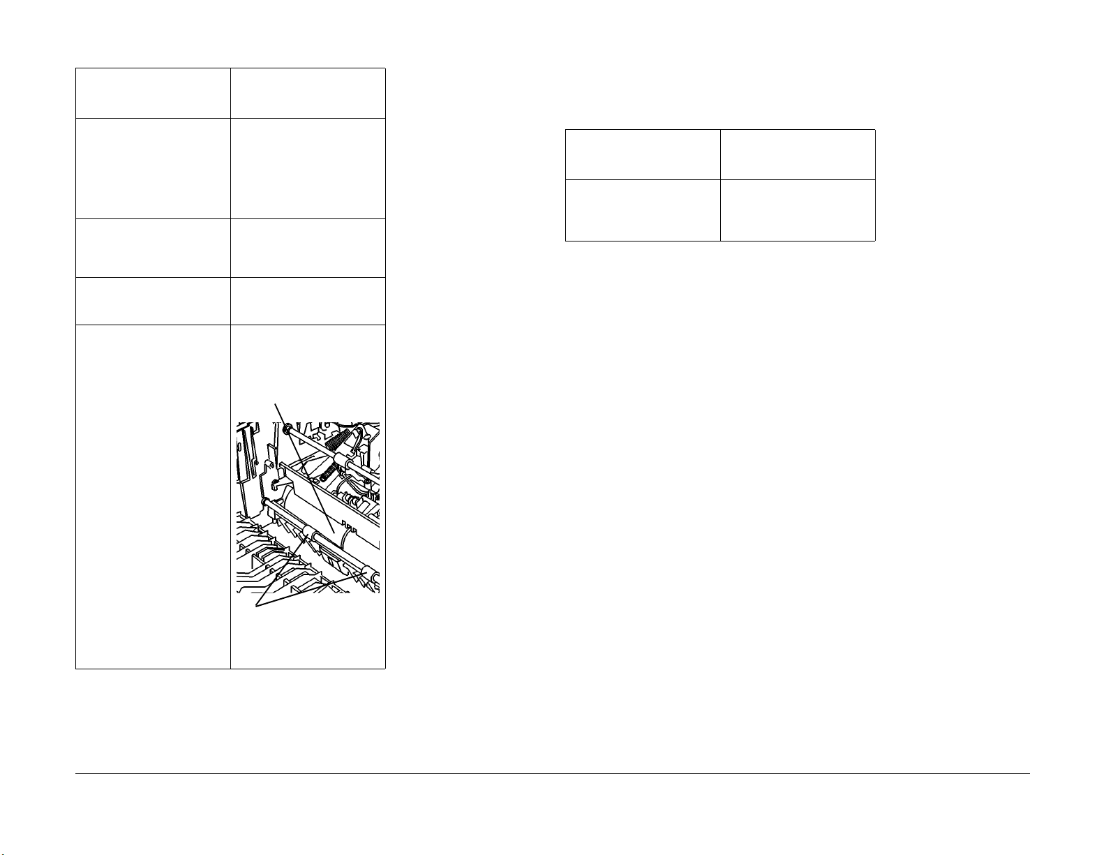
Table 5 Document Feeder (ADF)
Subsystem Maintenance Procedures
Perform this activity when
given direction in Call Flow
or RAP’s Materials
Clean Feed Roll, gentle push
Roll, Output Roll, Output
Pressure Roll, Exit Roll and
CVT Roll. Remove offset
Receiving Tray (REP 5.3) to
approach Feed Roll and gentle push Roll.
Clean CVT glass pad. If the
bottom of CVT glass is contanimated, do GP9 RIS/Mirror
cleaning.
Clean CVT Roll • Film Remover/General
Clean Exit Roll/Idler Roll • Film Remover/General
• Film Remover/General
Cleaning Solvent
• Lint-Free Cloth.
• Film Remover/General
Cleaning Solvent
• Lint-Free Cloth.
Cleaning Solvent
• Lint-Free Cloth.
Cleaning Solvent
• Lint-Free Cloth.
CVT Roll
CAUTION
Image Quality defects will occur if machine is on and cleaning solutions are used on covers.
Cooling Fan may draw cleaning solution vapor into machine. Switch off machine before clean-
ing so that Cooling Fan is off.
Table 6 Covers Subsystem Maintenance Procedures
Perform this activity when
given direction in Call Flow
or RAP’s Materials
Clean covers as necessary. • Formula A/All Purpose
Cleaner
• Heavy Duty Towel/Cleaning Cloth
Initial Issue
WorkCentre Pro 420
Exit Roll/Idler Roll
Figure 3 Registration
9/02
1-11
Service Call Procedures
Maintenance Procedures
Page 24

Service Call Procedures
Maintenance Procedures
9/02
1-12
Initial Issue
WorkCentre Pro 420
Page 25

Status Indicator RAPs
+5VDC POWER RAP...................................................................................................... 2-3
+24VDC POWER RAP.................................................................................................... 2-3
A1 RAP ........................................................................................................................... 2-4
A2 RAP ........................................................................................................................... 2-8
C1 RAP ........................................................................................................................... 2-11
C2 RAP ........................................................................................................................... 2-12
C3 RAP ........................................................................................................................... 2-14
C4 RAP ........................................................................................................................... 2-16
C5 RAP ........................................................................................................................... 2-18
C6 RAP ........................................................................................................................... 2-19
C7 RAP ........................................................................................................................... 2-20
C8 RAP ........................................................................................................................... 2-21
C9 RAP ........................................................................................................................... 2-22
E1 RAP ........................................................................................................................... 2-23
E2 RAP ........................................................................................................................... 2-27
J1 RAP............................................................................................................................ 2-31
J4 RAP............................................................................................................................ 2-32
J6 RAP............................................................................................................................ 2-32
J3 RAP............................................................................................................................ 2-33
J6 RAP............................................................................................................................ 2-33
J8 RAP............................................................................................................................ 2-33
J9 RAP............................................................................................................................ 2-33
J7 RAP............................................................................................................................ 2-34
U1 RAP ........................................................................................................................... 2-35
U2 RAP ........................................................................................................................... 2-36
U3 RAP ........................................................................................................................... 2-38
U4 RAP ........................................................................................................................... 2-40
U5 RAP ........................................................................................................................... 2-42
U6 RAP ........................................................................................................................... 2-43
U7, U8 RAP..................................................................................................................... 2-44
U9 RAP ........................................................................................................................... 2-46
Other Faults
OF 1-1 CONTROL PANEL RAP..................................................................................... 2-47
OF 1-2 MACHINE RUN RAP.......................................................................................... 2-48
OF 1-3 COOLING FAN RAP........................................................................................... 2-51
OF 2-1 BLANK DISPLAY RAP........................................................................................ 2-54
OF 7-1 PAPER TRAY RAP............................................................................................. 2-58
OF 8-1 PAPER DAMAGE or STACKING RAP............................................................... 2-60
OF 14-1 PRINTER RAP.................................................................................................. 2-62
OF 16-1 NOISE or ODOR RAP ...................................................................................... 2-64
OF 16-2 GROUND RAP.................................................................................................. 2-66
2 Status Indicator RAP/Other Faults
Initial Issue
WorkCentre Pro 420
9/02
2-1
Status Indicator RAP/Other Faults
Page 26

Status Indicator RAP/Other Faults
9/02
2-2
Initial Issue
WorkCentre Pro 420
Page 27

+5VDC POWER RAP
CR2 on MAIN PWB is turned on.
YN
Turn OFF the power.
Check the connection between P/J 109 on MAIN PWB and LVPS.
This connection is in good condition.
YN
Reconnect MAIN PWB and LVPS.
+24VDC POWER RAP
The voltage between P/J102-(+) and GND(-) on MAIN PWB has +24VDC.
YN
Turn OFF the power.
Check the Connection between P/J 109 on MAIN PWB and LVPS.
This connection is in good condition.
YN
Reconnect MAIN PWB and LVPS.
Turn ON the power.
Check the voltage between P109-C9(+) and GND(-) on MAIN PWB.
Approximately +5VDC is measured.
YN
The voltage between P/J205-2 and P/J205-3 on LVPS has approximately 110/
220VAC.
YN
Check the voltage between ACN and ACH on POWER CORD.
Approximately 110/220VAC are measured.
YN
Check the power cord.
If no problems are found, check the customer's power supply.
Replace POWER SUPPLY PWB
Replace LVPS.
Replace MAIN PWB.
Check the wire between MAIN PWB and the applicable component for an open circuit or poor
contact by referring to BSD CHI.
Turn ON the power.
Check the Voltage between P109-A31(+) and GND(-) on MAIN PWB.
Approximately +24VDC is measured.
YN
The voltage between P/J205-2 and P/J205-3 on LVPS has approximately 110/
220VAC.
YN
Check the Voltage between ACN and ACH on POWER CORD.
Approximately 110/220VAC are measured.
YN
Check the power cord.
If no problems are found, check the customer's power supply.
Replace POWER SUPPLY PWB
Replace LVPS.
Replace MAIN PWB.
Check the wire between MAIN PWB and the applicable component for an open circuit or poor
contact by referring to BSD CHI.
Initial Issue
WorkCentre Pro 420
9/02
2-3
Status Indicator RAP/Other Faults
A1
Page 28

A1 RAP
A1–1: Document can not actuate Pre Regi Sensor after Document Solenoid is energized.
Initial Actions
• Ensure ADF hinges firmly lean against Top Cover.
• Ensure ADF is securely closed. Repair as required.
• Ensure offset catch tray is correctly installed if it was removed recently.
Procedure
Remove ADF drive cover and offset catch tray. Observe the gentle push roll when switching on
or off power source of machine.
The gentle push roll must rapidly moves down and up.
YN
Remove ADF Rear Cover.
Enter [5-5] and turned ON.
The voltage between P/J605-4(+) and GND(-) on ADF PWB has +24VDC.
YN
The voltage between Pin 2(+) and GND(-) on Nudger Solenoid has +24VDC.
YN
The voltage between Pin 1(+) and GND(-) on Nudger Solenoid has 0VDC.
YN
Status Indicator RAP/Other Faults
A1
9/02
2-4
Initial Issue
WorkCentre Pro 420
Page 29

B
CVT Motor rotates.
YN
When [5-1] is turned ON, the voltage between P/J603-1(+) and GND(-) on ADF PWB
has approximately +1.3VDC.
YN
When [5-1] is turned ON, the voltage between P/J103-1(+) and GND(-) on MAIN
PWB has approximately +1.3VDC.
YN
Replace MAIN PWB.
Check wire between P/J103-1 on MAIN PWB and P/J603-1 on ADF PWB for an
open circuit or poor contact.
C
Document Feed Clutch is energized.
YN
When [5-7] is turned ON, the voltage between P/J605-1(+) and GND(-) on ADF PWB
has +24VDC.
YN
The voltage between Pin 2(+) and GND(-) on Document Feed Clutch has
+24VDC.
YN
The voltage between Pin 1(+) and GND(-) on Document Feed Clutch has
0VDC.
YN
Replace Nudger Solenoid.
When [5-1] is turned ON, the voltage between P/J603-2(+) and GND(-) on ADF PWB
has approximately +10VDC.
YN
When [5-1] is turned ON, the voltage between P/J603-3(+) and GND(-) on ADF
PWB has approximately +5VDC.
YN
Replace MAIN PWB.
Check the wire between P/J103-2 on MAIN PWB and P/J603-21 on ADF PWB for an
open circuit or poor contact.
When [5-1] is turned ON, the voltage between P/J603-3(+) and GND(-) on ADF PWB
has approximately +5VDC.
YN
When [5-1] is turned ON, the voltage between P/J103-3(+) and GND(-) on MAIN
PWB has approximately +10VDC.
YN
Replace MAIN PWB.
Check the wire between P/J103-3 on MAIN PWB and P/J603-3 on ADF PWB for an
open circuit or poor contact.
When [5-1] is turned ON, the voltage between P/J601-2(+) and GND(-) on ADF PWB
has approximately +10VDC.
YN
The Voltage between P/J602-1(+) and GND(-) on ADF PWB has +24VDC.
Replace CVT MOTOR.
Enter[5-7] and press START button.
The voltage between P/J605-5(+) and GND(-) on ADF PWB has +24VDC
YN
GO TO +24VDC Power FIP.
Check the wire between P/J605-5 on ADF PWB and Pin 1 on Document Feed
Clutch for an open circuit or poor contact.
Check the wire between P/J605-1 on ADF PWB and Pin 2 on Document Feed Clutch
for an open circuit or poor contact.
The voltage between P/J603-10(+) and GND(-) on ADF PWB has +5VDC.
YN
The voltage between P/J103-10(+) and GND(-) on MAIN PWB has +5VDC.
YN
Replace MAIN PWB.
Check the wire between P/J103-10 on MAIN PWB and P/J603-10 on ADF PWB for
an open circuit or poor contact.
Replace ADF PWB.
Enter [5-9].
C
Initial Issue
WorkCentre Pro 420
9/02
2-5
D
Status Indicator RAP/Other Faults
A1
Page 30

D
Use hand or paper to actuate or deactuate Document Presence Sensor, display should
change between "0" and "1".
YN
Block the Document Presence Sensor with a blank sheet of paper.
"1"(Low) is displayed.
YN
The voltage between Pin 2(+) and GND(-) on Document Presence Sensor has
+5VDC.
YN
Check the wire between Pin 2 on Document Presence Sensor and P/J103-18
on MAIN PWB for an open circuit or poor contact. If no problems are found,
replace MAIN PWB.
The voltage between Pin 1(+) and Pin 3(-) on Document Presence Sensor has
+5VDC.
YN
The voltage between P/J605-10(+) and P/J605-12(-) on ADF PWB has
+5VDC.
YN
Go to +5VDC Power FIP.
Check wire of the following:
• Between P/J605-10 on ADF PWB and Pin 1 on Document Presence Sensor for an open circuit or poor contact.
• Between P/J605-12 on ADF PWB and Pin 3 on Document Presence Sensor for an open circuit or poor contact.
Check for contamination and improper installation of the Sensor. If no problems are
found, replace the Document Presence Sensor.
E
Document Feed Clutch is energized, and Document Feed Roll is rotated.
YN
Check the mechanical load of Document Feed Roll.
• Check CVT feed area for obstruction.
• Close ADF feed door, put in a sheet of document in Document Feed Tray. Enter [5-14] and
press START button. Document should be fed and reach Document Exit Tray. If document
is stopped or blocked, repeat the test while observing document and drive.
• If pre-input appears slow, clean or replace Feed Roll/Gentle push Roll.
• Enter [5-7], Document Feed Clutch is energized. Manually rotate counter-clockwise CVT
Roll ( opposite to normal direction) to check the rotation of Feed Rolls. Repair as required.
• If the failure of A1 status code continues, replace Document Feed Clutch.
Remove the blank sheet of paper from the Sensor.
"0"(High) is displayed.
YN
Remove the connector of Document Presence Sensor.
The display should change to "0" (High).
YN
Check the circuit between Pin 2 on Document Presence Sensor and P/J103-18
on MAIN PWB for a short circuit. If no problems are found, replace MAIN PWB.
Check installation of the Sensor and the extraneous light diffraction. If no problems
are found, replace Document Presence Sensor.
Check installation of the Sensor.
If the failure of A1-1 Status Code continues, replace Document Presence Sensor.
Enter [5-1] and press START button.
When CVT MOTOR rotates, enter [7] and press START button.
E
Status Indicator RAP/Other Faults
A1
9/02
2-6
Initial Issue
WorkCentre Pro 420
Page 31

Initial Issue
WorkCentre Pro 420
9/02
2-7
Status Indicator RAP/Other Faults
A1
Page 32

A2 RAP
A2–0: Document can not actuate Document Registration Sensor after actuating Document
Presence Sensor.
A2–1: After constant-speed feed motor is energized, document can not deactivate in time Document Registration Sensor.
Initial Actions
Ensure CVT glass is faced steadily to the registration edge. If top cover is removed, clean GP9
RIS /reflector.
Ensure ADF hinges lean steadily against top cover.
Ensure ADF feed door is securely closed.
Procedure
Enter [5-11].
Use hand or paper to actuate or deactuate Document Registration Sensor, display should
change between "0" and "1".
YN
Block the Document Registration Sensor with a blank sheet of paper.
"1"(Low) is displayed.
YN
The voltage between Pin 2(+) and GND(-) on Document Registration Sensor
has +5VDC.
YN
Check wire between Pin 2 on Document Registration Sensor and P/J103-17 on
MAIN PWB for an open circuit or poor contact. If no problems are found,
replace MAIN PWB.
The voltage between Pin 1(+) and Pin 3(-) on Document Registration Sensor
has +5VDC.
YN
The voltage between P/J609-1(+) and P/J609-3(-) on ADF PWB has +5VDC.
YN
Go to +5VDC Power FIP
Check wire of the following:
• Between P/J609-1 on ADF PWB and Pin 1 on Document Registration
Sensor for an open circuit or poor contact.
• Between P/J609-3 on ADF PWB and Pin 3 on Document Registration
Check for contamination and improper installation of the Sensor. If no problems are
found, replace Document Registration Sensor.
Remove the blank sheet of paper from the Sensor.
"0"(High) is displayed.
YN
Remove the connector of Document Registration Sensor.
The display should change to "0"(High).
YN
AB
AB
Status Indicator RAP/Other Faults
C
Sensor for an open circuit or poor contact.
Check the circuit between Pin 2 on Document Registration Sensor and P/J10317 on MAIN PWB for a short circuit. If no problems are found, replace MAIN
PWB.
A2
AB
Enter [5-1] and press START button
CVT Motor rotates.
YN
• Check CVT document transport area for obstruction.
• Close ADF feed door, put in a sheet of document in Document Feed Tray. Enter [5-14] and
9/02
2-8
C
Check installation of the Sensor and the extraneous light diffraction. If no problems
are found, replace Document Registration Sensor.
Check installation of the Sensor.
If the failure of either A2-0 or A2-1 Status Code continues, replace Document Registration
Sensor.
When [5-1] is turned ON, the voltage between P/J603-1(+) and GND(-) on ADF PWB
has approximately +1.3VDC.
YN
When [5-1] is turned ON, the voltage between P/J103-1(+) and GND(-) on MAIN
PWB has approximately +1.3VDC.
YN
Replace MAIN PWB.
Check the wire between P/J103-1 on MAIN PWB and P/J603-1 on ADF PWB for an
open circuit or poor contact.
When [5-1] is turned ON, the voltage between P/J603-2(+) and GND(-) on ADF PWB
has approximately +10VDC.
YN
When [5-1] is turned ON, the voltage between P/J103-2(+) and GND(-) MAIN
PWB has approximately +10VDC.
YN
Replace MAIN PWB.
Check wire between P/J103-2 on MAIN PWB and P/J603-2 on ADF PWB for an
open circuit or poor contact.
When [5-1] is turned ON, the voltage between P/J603-3(+) and GND(-) on ADF PWB
has approximately +5VDC.
YN
When [5-1] is turned ON, the voltage between P/J103-3(+) and GND(-) on MAIN
PWB has approximately +10VDC.
YN
Replace MAIN PWB.
Check wire between P/J103-3 on MAIN PW and P/J603-3 on ADF PWB for an open
circuit or poor contact.
When [5-1] is turned ON, the voltage between P/J601-2(+) and GND(-) on ADF PWB
has approximately +10VDC.
YN
The voltage between P/J602-1(+) and GND(-) on ADF PWB has +24VDC.
Replace CVT MOTOR.
press START button. Document should be fed and reach Document Exit Tray. If document
is stopped or blocked, repeat the test while observing document and drive.
Initial Issue
WorkCentre Pro 420
Page 33

A2–2: After constant-speed feed motor is energized, document can not actuate in time Docu-
ment Exit Switch.
A2–3: Document can not deactivate in time Document Exit Switch after deactivating Document
Registration Sensor.
Initial Actions
Ensure CVT glass is faced steadily to the registration edge. If top cover is removed, clean GP9
RIS /reflector.
Ensure ADF hinges lean steadily against top cover.
Ensure ADF feed door is securely closed.
Procedure
Enter [5-12].
Turned ON/OFF the Document Exit Switch with a blank sheet of paper.
Display should change between "0" and "1".
YN
Block the Document Exit Switch with a blank sheet of paper.
"1"(Low) is displayed.
YN
The voltage between Pin 1(+) and GND(-) on Document Exit Switch has +5VDC.
YN
Check wire between Pin 1 of Switch and P/J103-19 on MAIN PWB for an open
circuit or a poor contact. If no problems are found, replace MAIN PWB.
The voltage between Pin 2(+) and GND(-) on Document Exit Switch has +5VDC.
YN
Replace Document Exit Switch.
Check wire between Pin 2 on Document Exit Switch and P/J609-5 on ADF PWB for
an open circuit or poor contact. If no problems are found, replace ADF PWB.
Remove the blank sheet of paper from the Sensor.
The display should change to "0"(High).
YN
Remove the connector of Document Exit Switch.
The display should change to "0"(High).
YN
Check the circuit between Pin 1 on Document Exit Switch and P/J103-19 on
MAIN PWB for a short circuit. If no problems are found, replace MAIN PWB.
Replace Document Exit Switch.
Check Actuator for damage or breakage. Check attachment of SWITCH. If the failure of
either A2-2 or A2-3 Status Code continues, replace Document Exit Switch.
Enter [5-1] and press START button.
A
CVT Motor rotates.
YN
When [5-1] is turned ON, the voltage between P/J603-1(+) and GND(-) on ADF PWB
has approximately +1.3VDC.
YN
When [5-1] is turned ON, the voltage between P/J103-1(+) and GND(-) on MAIN
PWB has approximately +1.3VDC.
YN
Replace MAIN PWB.
Check wire between P/J103-1 on MAIN PWB and P/J603-1 on ADF PWB for an
open circuit or poor contact.
When [5-1] is turned ON, the voltage between J603-2(+) and GND(-) on ADF PWB
has approximately +10VDC.
YN
When [5-1] is turned ON, the voltage between P/J103-2(+) and GND(-) on MAIN
PWB has approximately +10VDC.
YN
Replace MAIN PWB.
Check wire between P/J103-2 on MAIN PWB and P/J603-21 on ADF PWB for an
open circuit or poor contact.
When [5-1] is turned ON, the voltage between P/J603-3(+) and GND(-) on ADF PWB
has approximately +5VDC.
YN
When [5-1] is turned ON, the voltage between P/J103-3(+) and GND(-) on MAIN
PWB has approximately +10VDC.
YN
Replace MAIN PWB.
Check wire between P/J103-3 on MAIN PWB and J603-3 on ADF PWB for an open
circuit or poor contact.
When [5-1] is turned ON, voltage between P/J601-2(+) and GND(-) on ADF PWB has
approximately +10VDC.
YN
The voltage between P/J602-1(+) and GND(-) on ADF PWB has +24VDC.
Replace CVT MOTOR.
• Check CVT document transport area for obstruction.
• Close ADF feed door, put in a sheet of document in Document Feed Tray. Enter [5-14] and
press START button. Document should be fed and reach Document Exit Tray. If document
is stopped or blocked, repeat the test while observing document and drive.
A
Initial Issue
WorkCentre Pro 420
9/02
2-9
Status Indicator RAP/Other Faults
A2
Page 34

A5–0: ADF Cover is open.
Procedure
ADF Cover Interlock Switch is turned ON by hand.
A5-0 is gone off.
YN
Close ADF Cover.
The voltage between P/J605-2(+) and GND(-) on ADF PWB has +24VDC.
YN
Close ADF Cover.
The voltage P/J605-1(+) and GND(-) on ADF PWB has +24VDC.
YN
The voltage between P/J602-1(+) and GND(-) on ADF PWB has +24VDC.
YN
Go to +24VDC Power FIP.
Replace ADF PWB.
Check the wire between P/J605 on ADF PWB and ADF Cover Interlock Switch for an
open circuit or poor contact. If no problems are found, replace ADF Cover Interlock
Switch.
The voltage between P/J103-15(+) and GND(-) on MAIN PWB has +5VDC.
YN
Replace MAIN PWB.
The voltage between P/J603-15(+) and GND(-) on ADF PWB has +5VDC.
YN
Check wire between P/J603-15 on ADF PWB and P/J103-15 on MAIN PWB for an
open circuit or poor contact.
Replace ADF PWB.
Adjustment with ADF Cover and ADF Interlock Switch is poor.
Check damage of ADF Interlock Switch Actuator and attachment of ADF Cover.
Status Indicator RAP/Other Faults
A2
9/02
2-10
Initial Issue
WorkCentre Pro 420
Page 35

C1 RAP
C1–0: Tray 1 fed paper did not actuate Tray 1 Takeaway Sensor in time after Tray 1 feed motor
is energized.
Initial Actions
• Remove paper from tray and fan it to ensure edges are separated. Refer to label on paper
tray and reinstall paper.
• Check Paper Guides are adjusted to the set paper size and properly laid.
Procedure
Clear C1 status code. Make a copy. After C1, remove rear cover, and open Tray 1 Access
Door. Paper is at the Takeaway roll.
YN
Make machine enter diagnostic state. Enter [7-13], press START button and check
Feed rolls. Feed rolls rotate.
YN
The operating sound of the Tray 1 Feed Motor is audible.
YN
When [7-13] is turned ON, the voltage between P/J403-1(+) and GND(-) on
Tray 1 Control PWB has approximately +16VDC.
YN
The voltage between P/J402-1(+) and GND(-) on Tray 1 Control PWB
has +24VDC.
YN
Go to +24VDC Power RAP.
Replace Tray 1 Control PWB.
Replace Tray 1 Feed Motor.
Enter [7-11] and ON.
Tray 1 Feed Clutch is in good condition.
YN
When [7-11] is turned ON, the voltage between P/J408-2(+) and GND(-) on
Tray 1 Control PWB has +24VDC.
YN
The voltage between P/J408-1(+) and GND(-) on Tray 1 Control PWB
has +24VDC.
YN
The voltage between P/J402-1(+) and GND(-) on Tray 1 Control
PWB has +24VDC.
YN
Go to +24VDC Power RAP.
A
Enter [7-7]. Use hand or paper to actuate or deactuate Tray 1 Takeaway Sensor, display
should change between "0" and "1".
YN
Block Tray 1 Takeaway Sensor with a blank sheet of paper.
"1"(Low) is displayed.
YN
The voltage between Pin 1(+) and GND(-) on Tray 1 Takeaway Sensor has
+5VDC.
YN
Check the voltage between Pin 1 on Tray 1 Takeaway Sensor and PWB P/J4052 on Tray 1 Control. If no problems are found replace Tray 1 Control PWB.
The voltage between Pin 3(+) and Pin 2(-) on Tray 1 Takeaway Sensor has
+5VDC.
YN
The voltage between P/J405-1 (+) and P/J405-3(-) on Tray 1 Control PWB
has +5VDC.
YN
Go to +5VDC Power FIP.
Check the following:
• Between P/J405-1 on Tray 1 Control PWB and Pin 3 on Tray 1 Takeaway
Sensor for an open circuit or poor contact.
• Between P/J405-3 on Tray 1 Control PWB and Pin 2 on Tray 1 Takeaway
Sensor for an open circuit or poor contact
Check for contamination and improper installation of the Sensor. If no problems are
found, replace Tray 1 Takeaway Sensor.
Remove the blank sheet of paper.
"0"(High) is displayed.
YN
Remove connector of Tray 1 Takeaway Sensor.
The display should change to "0"(High).
YN
Check circuit between Pin 1 on Tray 1 Takeaway Sensor and P/J405-2 on Tray
1 Control PWB for a short circuit. If no problems are found, replace Tray 1 Con-
trol PWB.
Check installation of the Sensor and the extraneous light diffraction. If no problems
are found, replace Tray 1 Takeaway Sensor.
Check installation of the Sensor.
If the failure of C1-0 Status Code continues, replace Tray 1 Takeaway Sensor.
Check Tray 1 Takeaway Sensor for mechanical failure. Repair as required.
Replace Tray 1 Control PWB.
Replace Tray 1 Feed Clutch.
Replace Tray 1 Control PWB.
Eliminate mechanical failure. If Feed Rolls can not operate, replace Clutch.
Remove Tray 1, check and clean Feed Roll and Retard Roll to see if they are aging.
YN
Clear paper path and ensure no mechanical resistance.
Replace Feed Roll and Retard Roll.
A
Initial Issue
WorkCentre Pro 420
9/02
2-11
Status Indicator RAP/Other Faults
C1
Page 36

C2 RAP
C2–0: Tray 2 fed paper did not actuate Tray 2 Takeaway Sensor in time after Tray 2 Feed Motor
energized.
Initial Actions
• Make a copy using Tray 1. If a status code is displayed, to RAP Takeaway Tray 1 status
code.
• Remove paper from tray and fan it to ensure edges are separated. Refer to label on paper
tray. Reinstall paper.
• Check Paper Guides are adjusted to the set paper size and properly laid.
Procedure
Clear C2 status code. Make a copy. After C2, remove Rear Cover and Rear Cover of Tray 2,
and open Tray 2 Access Door and Tray 1 Access Door. A sheet of paper is in Tray 2 Access
Door.
YN
Make machine enter diagnostic state. Enter [7-14], press START button and check
Feed rolls. Feed rolls rotate.
YN
The operating sound of the Tray 2 Feed Motor is audible.
YN
When [7-14] is turned ON, the voltage between P/J403-1(+) and GND(-) on
Tray 2 Control PWB has approximately +16VDC.
YN
The voltage between P/J402-1(+) and GND(-) on Tray 2 Control PWB
has +24VDC.
YN
Go to +24VDC Power RAP.
Replace Tray 2 Control PWB.
Replace Tray 2 Feed Motor.
Enter [7-12] and ON.
Tray 2 Feed Clutch is in good condition.
YN
When [7-12] is turned ON, the voltage between P/J408-2(+) and GND(-) on
Tray 2 Control PWB has +24VDC.
YN
The voltage between P/J408-1(+) and GND(-) on Tray 2 Control PWB
has +24VDC.
YN
The voltage between P/J402-1(+) and GND(-) on Tray 2 Control
PWB has +24VDC.
YN
Go to +24VDC Power RAP.
AB
YN
Clear paper path and ensure no mechanical resistance.
Replace Feed Roll and Retard Roll.
Enter [7-8]. Use hand or paper to actuate or deactuate Tray 2 Takeaway Sensor, display
should change between "0" and "1".
YN
Block Tray 2 Takeaway Sensor with a blank sheet of paper.
"1"(Low) is displayed.
YN
The voltage between Pin 1(+) and GND(-) on Tray 2 Takeaway Sensor has
+5VDC.
YN
Check the voltage between Pin 1 on Tray 2 Takeaway Sensor and PWB P/J4052 on Tray 2 Control. If no problems are found replace Tray 2 Control PWB.
The voltage between Pin 3(+) and Pin 2(-) on Tray 2 Takeaway Sensor has
+5VDC.
YN
The voltage between P/J405-1 (+) and P/J405-3(-) on Tray 2 Control PWB
has +5VDC.
YN
Go to +5VDC Power FIP.
Check the following:
• Between P/J405-1 on Tray 1 Control PWB and Pin 3 on Tray 2 Takeaway
Sensor for an open circuit or poor contact.
• Between P/J405-3 on Tray 1 Control PWB and Pin 2 on Tray 2 Takeaway
Sensor for an open circuit or poor contact.
Check for contamination and improper installation of the Sensor. If no problems are
found, replace Tray 2 Takeaway Sensor.
Remove the blank sheet of paper.
"0"(High) is displayed.
YN
Remove connector of Tray 2 Takeaway Sensor.
The display should change to "0"(High)
YN
Check circuit between Pin 1 on Tray 2 Takeaway Sensor and P/J405-2 on Tray
2 Control PWB for a short circuit. If no problems are found, replace Tray 2 Con-
trol PWB.
Check installation of the Sensor and the extraneous light diffraction. If no problems
are found, replace Tray 2 Takeaway Sensor.
Check installation of the Sensor.
If the failure of C1-0 Status Code continues, replace Tray 2 Takeaway Sensor.
Check Tray 2 Takeaway Sensor for mechanical failure. Repair as required.
Replace Tray 2 Control PWB.
Replace Tray 2 Feed Clutch.
Replace Tray 2 Control PWB.
Eliminate mechanical failure. If Feed Rolls can not operate, replace Clutch.
Remove Tray 2, check and clean Feed Roll and Retard Roll to see if they are aging.
AB
Status Indicator RAP/Other Faults
C2
9/02
2-12
Initial Issue
WorkCentre Pro 420
Page 37

Initial Issue
WorkCentre Pro 420
9/02
2-13
Status Indicator RAP/Other Faults
C2
Page 38

C3 RAP
C3–0: Bypass fed paper did not actuate IOT Registration Sensor in time after Bypass Feed
Solenoid energized.
C3–1: Bypass fed paper actuated IOT Registration Sensor too early after Bypass Feed Solenoid energized.
Initial Actions
• Turn paper so that topside faces down. Exchanging lead edge for trail edge will not be
effective.
• Check Paper Guides are adjusted to paper without pinching or squeezing paper.
Procedure
Select Bypass Tray and make a copy. Copy is delivered and machine is ready.
YN
Go to corresponding status code RAP.
Check position of Paper Lift Plate. There must be a gap between Bypass Feed Rolls and Pad
on Paper Lift Plate. Gap should be enough for 50 sheets of 80 g/m
Check that 50 sheets fit under Bypass Feed Roll. 50 sheets of paper fit.
YN
Lift Plate Cam is out of position. Lift Plate Cam Follower should be on high part of Lift
Plate Cam. Perform or Check the following.
• Open Door Module.
• Check Sector Gear for damage or breakage. Ensure Slot is present. If Sector Gear
goes wrong, replace Sector Gear.
• Manually rotate Sector Gear counterclockwise, while holding Lift Plate Cam Follower
away from Lift Plate Cam until cam follower is at position shown in figure 2.
• Sector Gear Spring should be in position shown. In this position Sector Gear cannot
be rotated clockwise (direction of normal rotation), unless Bypass Solenoid energized. Replace failed component if Sector Gear can be rotated clockwise without
stopping.
Load 10 sheets of paper in Bypass Tray. Select Bypass Tray. Observe Paper Lift Plate and
make 10 copies. Paper Lift Plate must lift lead edge of paper to Bypass Feed Roll to feed.
Paper Lift Plate lifts lead edge of paper up to Bypass Feed Roll before a C3 occurs.
YN
Problem is either Sector Gear, Sector Gear Spring, Bypass Feed Solenoid or Door Module.
• Open Door Module.
• Check Sector Gear for damage or breakage. Ensure slot is present. If there is problem with Sector Gear, replace Door Module.
Sector Gear is free of damage.
YN
Replace Door Module.
2
.
AB
YN
Reinstall Sector Gear Spring or replace Door Module.
Check Bypass Feed Solenoid.
• Open Door Module.
• Enter [8-5], observe Bypass Feed Solenoid and press START button. Bypass Feed
Solenoid should be energized.
Bypass Feed Solenoid energizes.
YN
Disconnect Bypass Feed Solenoid plug from P308 on PCM interface PWB.
Measure resistance (ohms) between two wires of Bypass Feed Solenoid plugs.
Resistance should be approximately 41 ohms or less.
Bypass Solenoid measures approximately 41 ohms or less.
YN
Replace Bypass Feed Solenoid.
Go into diagnostic mode and enter [8-5]. Measure voltage at P211-10 on
PCM PWB and press START button.
Voltage should change from +0.1VDC to +6VDC.
YN
Replace LVPS first, if no effects, replace MAIN PWB then.
Connect Bypass Feed Solenoid plug to P308 on PCM interface PWB.
Measure voltage at J311-10 on PCM interface PWB.
Approximately +24 VDC is measured.
YN
Replace PCM interface PWB.
Replace LVPS.
Enter [8-6]
Actuator of IOT Regi Sensor is turned ON/OFF by hand.
C
Check Sector Gear Spring condition and installation. Sector Gear Spring should be connected as shown and be free of damage. Bypass feed sequence depends on Sector Gear
Spring being in position shown. In this position, Sector Gear cannot be rotated clockwise
(direction of normal operation), unless Bypass Solenoid energizes.
Sector Gear Spring is connected as shown and is free of damage.
AB
Status Indicator RAP/Other Faults
C3
9/02
2-14
Initial Issue
WorkCentre Pro 420
Page 39

C
The display should change between "0" and "1".
YN
Block Sensor with a blank sheet of paper.
"1"(Low) is displayed.
YN
The voltage between Pin 1(+) and GND(-) on IOT Regi Sensor has +5VDC.
YN
Check the wire Pin 1 on IOT Regi Sensor and P/J211-3 on LVPS for an open
circuit or poor contact. (Including PCM PWB)
If no problems are found, check the connection between MAIN PWB and LVPS.
If the problem persists, replace LVPS, MAIN PWB in sequence.
The voltage between Pin 2(+)and Pin 3(-) on IOT Regi Sensor has +5VDC.
YN
The voltage between J306-2(+) and J306-3(-) on PCM PWB has +5VDC.
YN
Go to +5VDC Power RAP.
Check wire of the following:
• Between J306-2 on PCM PWB and Pin 2 on IOT Regi Sensor for an open
circuit or poor contact.
• Between J306-3 on PCM PWB and Pin 3 on IOT Regi Sensor for an open
circuit or poor contact
Check for contamination and improper installation of the Sensor. Check Actuator for
damage. If no problems are found, replace IOT Regi Sensor.
Remove the blank sheet of paper from the Sensor.
The display should change to "0"(High).
YN
Remove the connector of IOT Regi Sensor.
The display should change to "0"(High)
YN
Check the circuit between Pin 2 on IOT Regi Sensor and P/J211-3 on LVPS for
a short circuit. (Including PCM PWB).
If no problems are found, check the connection between MAIN PWB and LVPS.
If the problem persists, replace LVPS, MAIN PWB in sequence.
Check installation of the Sensor and the extraneous light diffraction. If no problems
are found, replace IOT Regi Sensor.
Check installation of the Sensor.
If the failure of either C3-0 or C3-1 Status Code continues, replace IOT Regi Sensor.
Replace Bypass Drives Kit. Paper Lift Plate failed to lift stack in a previous check.
Check machine operation after doing each item.
• Ensure Retard Pad Spring pushes Retard pad up against bottom of Bypass Feed Roll as
required .A problem here may also result in an E1 status code.
• Check for obstructions in Bypass Exit Guides.
• Check gear on Bypass Takeaway Roll Shaft. Check idlers that are driven by Bypass Take-
away Roll Shaft.
• Clean or replace Bypass Feed Roll.
Initial Issue
WorkCentre Pro 420
9/02
2-15
Status Indicator RAP/Other Faults
C3
Page 40

C4 RAP
C4-0: Tray 1 fed paper did not deactuate in time.
C4-1: Tray 1 fed paper did not actuate Registration Sensor in time.
C4-2: Tray 2 fed paper did not actuate Registration Sensor in time.
C4-3: Tray 1 fed paper actuated Registration Sensor too early after Tray 1 Feed Motor is ener-
gized.
C4-4: Tray 2 fed paper actuated Registration Sensor too early after Tray 2 Feed Motor is energized.
C4-5: Two-side fed paper did not actuate Registration Sensor in time.
C4-6: Two-side fed paper actuated Registration Sensor too early.
ABC
Remove the blank sheet of paper from the Sensor.
"0"(High) is displayed.
YN
D
• Between P/J405-3 on Tray 1 Control PWB and Pin 2 on Tray 1 Takeaway
Check for contamination and improper installation of the Sensor. If no problems are
found, replace Tray 1 Takeaway Sensor.
Remove the connector of Tray 1 Takeaway Sensor.
The display should change to "0"(High).
YN
Check installation of the Sensor and the extraneous light diffraction. If no problems
are found, replace Tray 1 Takeaway Sensor.
Sensor for an open circuit or poor contact
Check the circuit between Pin 1 on Tray 1 Takeaway Sensor and P/J405-2 on
Tray 1 Control PWB for a short circuit. If no problems are found, replace Tray 1
Control PWB.
Initial Actions
• Remove paper from tray and fan it to ensure edges are separated. Refer to label on paper
tray and reinstall paper.
• Check Paper Guides are adjusted to the set paper size and properly laid.
• Check that idler Roll Spring on Tray 1 Access Door pushes idler rolls against Takeaway
Rolls.
• Check that Inner Guide of Tray 1 Access Door is correctly installed.
Procedure
Switch off machine. Ensure no jammed paper in machine. Switch on machine. Machine is
ready to copy.
YN
Enter [7-7].
Block Tray 1 Takeaway Sensor with a blank sheet of paper.
"1"(Low) is displayed.
YN
The voltage between Pin 1(+) and GND(-) on Tray 1 Takeaway Sensor has
+5VDC.
YN
Check the wire between Pin 1 on Tray 1 Takeaway Sensor and P/J405-2 on
Tray 1 Control PWB for an open circuit or poor contact. If no problems are
found, replace Tray 1 Control PWB.
The voltage between Pin 3(+) and Pin 2(-) on Tray 1 Takeaway Sensor has
+5VDC.
YN
The voltage between P/J405-1(+) and P/J405-3(-) on Tray 1 Control PWB has
+5VDC.
YN
Go to +5VDC Power FIP.
Check wire of the following:
• Between P/J405-1 on Tray 1 Control PWB and Pin 3 on Tray 1 Takeaway
Sensor for an open circuit or poor contact.
Check installation of the Sensor.
If the failure of either C4-0, C4-1, C4-2, C4-3, C4-4, C4-5 or C4-6 Status Code continues,
replace Tray 1 Takeaway Sensor.
Go into diagnostic mode, enter [7-13] and press START button to actuate Tray 1 Feed Motor.
Takeaway Rolls rotate.
YN
Remove Rear Cover.
Manually rotate gear for Tray 1 Feed Motor.
Gear is free to rotate.
YN
Check Takeaway Roll Gear Module for mechanical failure.
Check circuit of Tray 1 Feed Motor.
Make machine go into diagnostic mode, enter [7-13] and press START. Measure voltage
between any pin on Feed Motor P403 and ground.
Approximately +16VDC is measured.
YN
Measure voltage at P402-1 on Tray 1 Control PWB.
Approximately +24VDC is measured
YN
Measure voltage at J302-1 on PCM interface PWB.
Approximately +24VDC is measured.
YN
Go to +24VDC Power RAP.
Check wire between J302-1 and P402-1. If there is damage, replace wires.
Replace Tray 1 Control PWB.
Replace Tray 1 Feed Motor.
Enter [8-6].
Actuator of IOT Regi Sensor is turned ON/OFF by hand.
ABC E
Status Indicator RAP/Other Faults
C4
D
9/02
2-16
Initial Issue
WorkCentre Pro 420
Page 41

E
The display should change between "0" and "1".
YN
Block the Sensor with a blank sheet of paper.
"1"(Low) is displayed.
YN
The voltage between Pin 1(+) and GND(-) on IOT Regi Sensor has +5VDC.
YN
Check the wire between Pin 1 on IOT Regi Sensor and P/J211-3 on LVPS for
an open circuit or poor contact. (Including PCM PWB).
If no problems are found, check the connection between MAIN PWB and LVPS.
If the problem persists, replace LVPS, MAIN PWB in sequence.
The voltage between Pin 2(+) and Pin 3(-) on IOT Regi Sensor has +5VDC.
YN
The voltage between J306-2(+) and J306-3(-) on PCM PWB has +5VDC.
YN
Go to +5VDC Power RAP.
Check wire of the following:
• Between J306-2 on PCM PWB and Pin 2 on IOT Regi Sensor for an open
circuit or poor contact.
• Between J306-3 on PCM PWB and Pin 3 on IOT Regi Sensor for an open
circuit or poor contact.
Check for contamination and improper installation of the Sensor. Check Actuator for
damage. If no problems are found, replace IOT Regi Sensor.
Remove the blank sheet of paper from the Sensor.
The display should change to "0"(High).
YN
Remove the connector of IOT Regi Sensor.
The display should change to "0"(High).
YN
Check the circuit between Pin 1 on IOT Regi Sensor and P/J211-3 on LVPS
(including PCM PWB) for a short circuit.
If no problems are found, check the connection between MAIN PWB and LVPS.
If the problem persists, replace LVPS, MAIN PWB in sequence.
Check installation of the Sensor and the extraneous light diffraction. If no problems
are found, replace IOT Regi Sensor.
F
Takeaway Rolls rotate.
YN
Remove Rear Cover of Tray 2.
Manually rotate Tray 2 Feed Motor.
Gear is free to rotate.
YN
Check that Takeaway Roll Gear Module is free of mechanical failure. Replace Takeaway Roll Gear, if any.
Check circuit of Tray 2 Feed Motor.
Measure voltage at any pin of P403 on Tray 2 Control PWB.
Approximately +24VDC is measured.
YN
Measure voltage at P402-1 on Tray 2 Control PWB.
Approximately +24VDC is measured.
YN
Measure voltage at P402-1 on Tray 2 Control PWB.
Approximately +24VDC is measured.
YN
Measure voltage at P402-1 on Tray 1 Control PWB.
Approximately +24 VDC is measured.
YN
Measure voltage at J302-1 on PCM interface PWB.
Approximately +24 VDC is measured.
YN
Go to +24VDC RAP 1.
Check wire between J302-1 and P402-1. If there is any damage,
replace wires.
Replace Tray 1 Control PWB.
Check wire between Tray 2 P402-1 and Tray 1 P401-1. If there is any damage,
replace wires.
Replace Tray 2 Control PWB.
Replace Tray 2 Feed Motor.
Check that paper path is free of torn paper, glue backed labels or other obstructions.
Check installation of the Sensor.
If the failure of either C4-0, C4-1, C4-2, C4-3, C4-4, C4-5 or C4-6 Status Code continues,
replace IOT Regi Sensor.
Tray 2 is installed.
YN
Ensure paper path is free of torn paper, glue backed labels or other obstructions.
Go into diagnostic mode, enter [7-14] and press START button to actuate Tray 2 Feed Motor.
F
Initial Issue
WorkCentre Pro 420
9/02
2-17
Status Indicator RAP/Other Faults
C4
Page 42

C5 RAP
C5–0: Tray 1 No Paper Sensor is not actuated.
Procedure
Remove Tray 1 module.
Switch on power, go into diagnostic mode, enter [7-5] and press START button.
Manually handle the actuating arm of Tray 1 No Paper Sensor.
Display changes between "0" and "1".
YN
The voltage between Pin 1(+) and GND(-) on Tray 1 No Paper Sensor has +5VDC.
YN
Check wire between Pin 1 on Tray 1 No Paper Sensor and P/J404-1 on Tray 1 Control PWB for an open circuit or poor contact. If no problems are found, replace Tray 1
Control PWB.
If the problem persists, replace MAIN PWB.
The voltage between Pin 3(+) and Pin 2(-) on Tray 1 No Paper Sensor has +5VDC.
YN
The voltage between P/J404-3(+) and P/J404-2(-) on Tray 1 Control PWB has
+5VDC.
YN
Go to +5VDC Power RAP.
Check wire of the following:
• Between P/J404-3 on Tray 1 Control PWB and Pin 3 on Tray 1 No Paper Sensor for an open circuit or poor contact.
• Between P/J404-2 on Tray 1 Control PWB and Pin 2 on Tray 1 No Paper Sensor for an open circuit or poor contact. If no problems are found, replace Tray 1
Check for contamination and improper installation of the Sensor. If no problems are found,
replace Tray 1 No Paper Sensor.
Check the installation position of no paper Sensor for any problem. Repair as required.
Control PWB.
Status Indicator RAP/Other Faults
C5
9/02
2-18
Initial Issue
WorkCentre Pro 420
Page 43

C6 RAP
C6–0: Tray 2 No Paper Sensor is not actuated.
Procedure
Remove Tray 2 module.
Switch on power, go into diagnostic mode, enter [7-6] and press START button.
Manually handle the actuating arm of Tray 2 No Paper Sensor.
Display changes between "0" and "1".
YN
The voltage between Pin 1(+) and GND(-) on Tray 2 No Paper Sensor has +5VDC.
YN
Check the wire Pin 1 on Tray 2 No Paper Sensor and J404-1 on Tray 2 Control PWB
for an open circuit or poor contact. If no problems are found, replace Tray 2 Control
PWB. If the problem persists, replace Tray 1 Control PWB and MAIN PWB.
The voltage between Pin 3(+) and Pin2(-) on Tray 2 No Paper Sensor has +5VDC.
YN
The voltage between P/J404-3(+) and P/J404-2(-) on Tray 2 Control PWB has
+5VDC.
YN
Go to +5VDC Power RAP.
Check wire of the following:
• Between P/J404-3 on Tray 2 Control PWB and Pin 3 on Tray 2 No Paper Sensor for an open circuit or poor contact.
• Between P/J404-2 on Tray 2 Control PWB and Pin 2 on Tray 2 No Paper Sensor for an open circuit or poor contact.
If no problems are found, replace Tray 2 Control PWB. If the problem persists,
replace Tray 1 Control PWB.
Check for contamination and improper installation of the Sensor. If no problems are found,
replace Tray 2 No Paper Sensor.
Check the installation position of no paper Sensor for any problem. Repair as required.
Initial Issue
WorkCentre Pro 420
9/02
2-19
Status Indicator RAP/Other Faults
C6
Page 44

C7 RAP
C7-0: Tray 1 Size Switch is not actuated.
Procedure
Remove Tray1.
Check Tray 1 Paper Size Actuator.
The Actuator is in good condition.
YN
Repair the Actuator, and replace it if necessary.
Check conductivity of the following:
• Between Tray 1 Size Switch CN1-1 and Tray 1 Control PWB P/J406-1
• Between Tray 1 Size Switch CN1-2 and Tray 1 Control PWB P/J406-2
• Between Tray 1 Size Switch CN1-3 and Tray 1 Control PWB P/J406-3
• Between Tray 1 Size Switch CN1-4 and Tray 1 Control PWB P/J406-4
• Between Tray 1 Size Switch CN1-5 and Tray 1 Control PWB P/J406-5
The resistance is below 1 Ohm for all.
YN
Check the open circuit or poor contact where the resistance is not below 1 Ohm.
Replace Tray 1 Size Switch.
If the problem persists, replace Tray 1 Control PWB.
Status Indicator RAP/Other Faults
C7
9/02
2-20
Initial Issue
WorkCentre Pro 420
Page 45

C8 RAP
C8–0: Tray 2 Size Switch is not actuated.
Procedure
Remove Tray 2.
Check Tray 2 Paper Size Actuator.
The Actuator is in good condition.
YN
Repair the Actuator, and replace it if necessary.
Check conductivity of the following:
• Between Tray 2 Size Switch CN1-1 and Tray 2 Control PWB P/J406-1
• Between Tray 2 Size Switch CN1-2 and Tray 2 Control PWB P/J406-2
• Between Tray 2 Size Switch CN1-3 and Tray 2 Control PWB P/J406-3
• Between Tray 2 Size Switch CN1-4 and Tray 2 Control PWB P/J406-4
• Between Tray 2 Size Switch CN1-5 and Tray 2 Control PWB P/J406-5
The resistance is below 1 Ohm for all.
YN
Check the open circuit or poor contact where the resistance is not below 1 Ohm.
Replace Tray 2 Size Switch.
If the problem persists, replace Tray 2 Control PWB.
Initial Issue
WorkCentre Pro 420
9/02
2-21
Status Indicator RAP/Other Faults
C8
Page 46

C9 RAP
C9–0: Tray 2 fed paper did not actuate Tray 1 Takeaway Sensor in time.
Procedure
Enter [7-7]. Use hand or paper to actuate or deactuate Tray 1 Takeaway Sensor, display should
change between "0" and "1".
YN
Block Tray 1 Takeaway Sensor with a blank sheet of paper.
"1"(Low) is displayed.
YN
The voltage between Pin 1(+) and GND(-) on Tray 1 Takeaway Sensor has
+5VDC.
YN
Check the wire between Pin 1 on Tray 1 Takeaway Sensor and P/J405-2 on
Tray 1 Control PWB for an open circuit or poor contact. If no problems are
found, replace Tray 1 Control PWB.
The voltage between Pin 3(+) and Pin 2(-) on Tray 1 Takeaway Sensor has
+5VDC.
YN
The voltage between P/J405-1 (+) and P/J405-3(-) on Tray 1 Control PWB
has +5VDC.
YN
Go to +5VDC Power FIP.
Check wire of the following:
• Between P/J405-1 on Tray 1 Control PWB and Pin 3 on Tray 1 Takeaway
Sensor for an open circuit or poor contact.
• Between P/J405-3 on Tray 1 Control PWB and Pin 2 on Tray 1 Takeaway
Sensor for an open circuit or poor contact.
Check for contamination and improper installation of the Sensor. If no problems are
found, replace Tray 1 Takeaway Sensor.
B
If the failure of C9-0 Status Code continues, replace Tray 1 Takeaway Sensor.
Enter [7-14] and Press the START button.
Tray 2 Feed Motor rotates.
YN
The voltage between P/J402-1(+) and GND(-) on Tray 2 Control PWB has +24VDC.
YN
Go to +24VDC Power RAP.
Replace Tray 2 Control PWB
Enter [7-12] and press the START button.
Tray 2 Feed Clutch is energized.
YN
When [7-12] is turned ON?the voltage between P/J408-2(+) and GND(-) on Tray 2
Control PWB has 0VDC.
YN
Replace Tray 2 Control PWB.
The voltage between P/J408-1(+) and GND(-) on Tray 2 Control PWB has +24VDC.
YN
The voltage between P/J402-1(+) and GND(-) on Tray 2 Control PWB has
+24VDC.
YN
Go to +24VDC Power RAP.
Replace Tray 2 Control PWB
Replace Tray 2 Feed Clutch.
Check the mechanical load of Tray 2 Feed Gear.
• Remove paper from tray and fan it to ensure edges are separated. Refer to label on paper
tray and reinstall paper.
• Check that Paper Guides are adjusted to the set paper size position and properly laid.
Remove the blank sheet of paper from the Sensor.
"0"(High) is displayed.
YN
Remove the connector of Tray 1 Takeaway Sensor.
The display should change to "0"(High).
YN
Check the circuit between Pin 1 on Tray 1 Takeaway Sensor and J405-2 on Tray
1 Control PWB for a short circuit. If no problems are found, replace Tray 1 Control PWB.
Check installation of the Sensor and the extraneous light diffraction. If no problems
are found, replace Tray 1 Takeaway Sensor.
Check installation of the Sensor.
AAB
Status Indicator RAP/Other Faults
C9
9/02
2-22
Initial Issue
WorkCentre Pro 420
Page 47

E1 RAP
E1–1: Paper did not actuate Fuser Switch in time after Registration Clutch energized.
E1–3: Paper did not deactuate Fuser Exit Switch in time after de-actuating Registration Sen-
sor.
Procedure
Enter [10-6].
Turn ON/OFF Fuser Exit Switch by hand.
The display should change.
YN
Remove Fuser Module. Measure resistance (ohms) between J211B-2 and 3 on Fuser
Module. While measuring resistance, actuate and deactuate Fuser Exit Switch. Resistance should change from high resistance to less than 30 ohms to high resistance. Resis-
tance changes while actuating and de-actuating Fuser Exit Switch.
YN
Replace Fuser Module.
Check the wire of the following:
• Between J203-1 on LVPS and J211A-2 on Fuse Module for an open circuit or poor
contact.
• Between J203-2 on LVPS and J211A-3 on Fuser Module for an open circuit or poor
contact.
If no problems are found, replace Fuser Module, MAIN PWB in sequence.
Enter [8-3] and ON.
IOT Regi Clutch is energized
YN
Enter [8-3] and ON.
The voltage between P/J211-8(+) and GND(-)on LVPS has 0VDC.
YN
Check the connection between MAIN PWB and LVPS. If no problems are found,
replace LVPS, MAIN PWB in sequence.
When [8-3] is turned ON, the voltage between PCM PWB J311-8(+) and GND(-) has
0VDC.
YN
Check the wire between P/J211-8 on LVPS and J311-8 on PCM PWB for an open
circuit or poor contact.
A
Check installation of Registration Assembly. Registration Assembly is installed correctly.
YN
Repair as required.
Check installation of Transfer Detack Corotron. Corotron is correctly installed.
YN
Repair as required.
Do following to verify operation of Registration Roll Drives.
• Remove Rear Cover.
• Push Registration Roll Assembly up and into operational position while partially closing
Door Module.
• Hold Registration Roll Assembly in this position and manually rotate Drive Motor in a
counterclockwise direction while observing Registration Clutch Drive Gear and related
drives.
Registration Roll drives appear to operate normally and without visual evidence of drive
gear breakage or damage.
YN
Repair or replace components as required.
Manually rotate Drive Motor in a counterclockwise direction while observing Fuser Drives and
rotation of visible portions of Fuser Rolls. Drive of Fuser Module Drives appears to operate
normally and without visual evidence of drive gear breakage or damage.
YN
Repair or replace components as required.
Replace Registration Sensor. Verify any problem continues.
Run customer job and after E1 is displayed, slowly open Door Module just enough to check
position of lead edge of paper. Paper is stalled before entering Registration Assembly.
YN
Paper is stalled at Fuser Module.
YN
Remove Fuser Module.
Check that Pre Fuser Guide feels smooth and free of damage or has a condition that
may stop paper movement.
Replace Fuser Module.
Replace Registration Module.
When [8-3] is turned ON, the voltage between P/J305-4(+) and GND(-) on PCM PWB
has +24VDC.
YN
Replace PCM PWB.
The voltage between P/J305-1(+) and GND(-) on PCM PWB has +24VDC.
YN
Refer to BSD CH1.3, check Front Intlk On +24VDC circuit to P/J305-1 on PCM PWB.
Replace IOT Regi Clutch.
A
Initial Issue
WorkCentre Pro 420
9/02
2-23
Status Indicator RAP/Other Faults
E1
Page 48

E1-2: Paper did not deactuate Registration Sensor in time after actuating Fuser Exit Switch.
Procedure
Enter [8-6]
The actuator of IOT Regi Sensor is turned ON/OFF by hand.
The display should change between "0" and "1".
YN
Block Sensor with a blank sheet of paper.
"1"(Low) is displayed.
YN
The voltage between Pin 1 on IOT Regi Sensor(+) and GND(-) has +5VDC.
YN
Check wire between Pin on IOT Regi Sensor and P/J211-4 on LVPS for an
open circuit or poor contact. (Including PCM PWB)
If no problems are found, check the connection between LVPS and MAIN PWB.
If problem continues, replace LVPS, MAIN PWB in sequence.
The voltage between Pin 2(+) and Pin 3(-) on IOT Regi Sensor has +5VDC.
YN
The voltage between P/J306-2(+) and P/J306-3(-) on PCM PWB has
+5VDC.
YN
Go to +5VDC Power RAP.
Check the following:
• Between on P/J306-2 PCM PWB and Pin 2 on IOT Regi Sensor for an
open circuit or poor contact.
• Between P/J306-3 on PCM PWB and Pin 3 on IOT Regi Sensor for an
open circuit or poor contact.
Check for contamination and improper installation of the Sensor. Check Actuator for
damage. If no problems are found, replace the IOT Regi Sensor.
Remove the blank sheet of paper.
"0"(High) is displayed.
YN
Remove the connector of IOT Regi Sensor.
The display should change to "0"(High).
YN
Check the circuit between Pin 1 on IOT Regi Sensor and P/J211-3 on LVPS for
a short circuit. (Including PCM PWB)
If no problems are found, check the connection between MAIN PWB and LVPS.
If a problem continues, replace LVPS, MAIN PWB in sequence.
Check installation of the Sensor and the extraneous light diffraction. If no problems
are found, replace Tray 1 Takeaway Sensor.
Check installation of the Sensor.
If the failure of E1-2 Status Code continues, replace IOT Regi Sensor.
Check installation of Registration Assembly.
Registration Assembly is installed correctly.
YN
Repair as required.
Check installation of Transfer Detack Corotron.
Corotron is correctly installed.
YN
Repair as required.
Do following to verify operation of Registration Roll Drives.
• Remove Rear Cover.
• Push Registration Roll Assembly up and into operational position while partially closing
Door Module.
• Hold Registration Roll Assembly in this position and manually rotate Drive Motor in a
counterclockwise direction while observing Registration Clutch Drive Gear and related
drives.
Registration Roll drives appear to operate normally and without visual evidence of drive
gear breakage or damage.
YN
Repair or replace components as required.
Manually rotate Drive Motor in a counterclockwise direction while observing Fuser Drives and
rotation of visible portions of Fuser Rolls.
Drive of Fuser Module Drives appears to operate normally and without visual evidence
of drive gear breakage or damage.
YN
Repair or replace components as required.
Status Indicator RAP/Other Faults
E1
Replace Registration Sensor. Verify any problem continues.
Run customer job and after E1 is displayed, slowly open Door Module just enough to check
position of lead edge of paper.
Paper is stalled before entering Registration Assembly.
YN
Paper is stalled at Fuser Module.
YN
Remo
Run customer job and after E1 is displayed, slowly open Door Module just enough to check
position of lead edge of paper.
9/02
2-24
Paper is stalled before entering Registration Assembly.
YN
Paper is stalled at Fuser Module.
YN
Remo
Run customer job and after E1 is displayed, slowly open Door Module just enough to check
WorkCentre Pro 420
Initial Issue
Page 49

A
Enter [8-4] and ON.
The operating sound of the Gate Select Solenoid is audible.
YN
When [8-4] is turned ON, the voltage between P/J211-11(+) and GND(-) on LVPS has
+24VDC.
YN
When [8-4] is turned ON, the voltage between P/J311-11(+) and GND(-) on PCM
PWB has +24VDC.
YN
When [8-4] is turned ON, the voltage between P/J307-2(+) and GND(-) on
PCM PWB has +24VDC.
YN
The voltage between J307-1(+) and GND(-) on PCM PWB has +24VDC.
YN
Go to +24VDC Power RAP.
Replace Gate Select Solenoid.
Replace PCM PWB.
Check the wire between P/J211-11 on LVPS and P/J311-11 on PCM PWB for an
open circuit or poor contact.
Check the connection between MAIN PWB and LVPS. If no problems are found, replace
LVPS, MAIN PWB in sequence.
Check the following:
• The drive transfer course from MAIN MOTOR to DOOR EXIT ROOL for no problem.
• A paper transportation failure due to foreign substance on the paper path.
Status Indicator RAP/Other Faults
E1
9/02
2-26
Initial Issue
WorkCentre Pro 420
Page 50

E2 RAP
E2-1: Paper can not actuate in time OCT Exit Sensor after leaving Fuser Exit Switch.
E2-2: Paper can not deactuate in time OCT Exit Sensor after leaving Fuser Exit Switch.
Procedure
Enter [5-13].
Actuator of Copy Exit Sensor is turned ON/OFF by hand. The display should change between
"0" and "1".
YN
Block the Sensor with a blank sheet of paper.
"1"(Low) is displayed.
YN
Remove the ADF Drive Cover.
The voltage between Pin 2(+) and GND(-) on Copy Exit Sensor has +5VDC.
YN
Check the wire between Pin 2 on Copy Exit Sensor and P/J103-20 on MAIN
PWB for an open circuit or poor contact. (Including ADF PWB)
If no problems are found, replace MAIN PWB.
The voltage between Pin 1(+) and Pin 3(-) on Copy Exit Sensor has +5VDC.
YN
The voltage between P/J608-1(+) and P/J306-3(-) on ADF PWB has +5VDC.
YN
Go to +5VDC Power RAP.
Check wire of the following:
• Between P/J608-1 on ADF PWB and Pin 1 on Copy Exit Sensor for an
open circuit or poor contact.
• Between P/J608-3 on ADF PWB and Pin 3 on Copy Exit Sensor for open
circuit or poor contact.
Check for contamination and improper installation of the Sensor. Check Actuator for
damage. If no problems are found, replace the Copy Exit Sensor.
Remove the blank sheet of paper from the Sensor.
The display should change to "0"(High).
YN
Remove the connector of Copy Exit Sensor.
This display should change to "0"(High).
YN
Check the circuit between Pin 2 on Copy Exit Sensor and P/J103-20 on MAIN
PWB for short circuit. (Including ADF PWB)
If no problems are found, replace MAIN PWB.
A
Enter [8-4] and ON.
The operating sound of the Gate Select Solenoid is audible.
YN
When [8-4] is turned ON, the voltage between P/J211-11(+) and GND(-) on LVPS has
+24VDC.
YN
When [8-4] is turned ON, the voltage between P/J311-11(+) and GND(-) on PCM
PWB has +24VDC.
YN
When [8-4] is turned ON, the voltage between P/J307-2(+) and GND(-) on
PCM PWB has +24VDC.
YN
The voltage between P/J307-1(+) and GND(-) on PCM PWB has
+24VDC.
YN
Go to +24VDC Power RAP.
Replace Gate Select Solenoid.
Replace PCM PWB.
Check wire between J211-11 on LVPS and J311-11 on PCM PWB for an open circuit
or poor contact.
Check the connection between MAIN PWB and LVPS. If no problems are found, replace
LVPS, MAIN PWB in sequence.
Enter [5-3] and turned ON.
Copy Exit Motor rotates.
YN
The Voltage between P/J602-1(+) and GND(-) on ADF PWB has +24VDC.
YN
Go to +24VDC RAP.
When [5-3] is turned ON, the voltage between P/J603-9(+) and GND(-) on ADF PWB
has 0VDC.
YN
When [5-3] is turned ON, the voltage between J103-9(+) and GND(-) on MAIN PWB
has 0VDC.
YN
Replace MAIN PWB.
Check wire between P/J103-9 on MAIN PWB and P/J603-9 on ADF PWB for an
open circuit or poor contact.
Check installation of the Sensor and the extraneous light diffraction. If no problems
are found, replace Copy Exit Sensor.
Check installation of the Sensor.
If the failure of either E2-1 or E2-2 Status Code continues, replace Copy Exit Sensor.
A
Initial Issue
WorkCentre Pro 420
ABC
9/02
2-27
The Voltage between P/J603-8(+) and GND(-) on ADF PWB has 0VDC.
YN
The voltage between P/J103-8(+) and GND(-) on MAIN PWB has +0VDC.
YN
Replace MAIN PWB.
Status Indicator RAP/Other Faults
E2
Page 51

BCD
Check the wire between P/J103-8 on MAIN PWB and P/J603-8 on ADF PWB for an
open circuit or poor contact.
When [5-3] is turned ON, the voltage between P/J603-7(+) and GND(-) on ADF PWB
has +0.22VDC.
YN
The voltage between P/J103-7(+) and GND(-) on MAIN PWB has +0.22VDC.
YN
Replace MAIN PWB.
Check the wire between P/J103-7 on MAIN PWB and P/J603-7 on ADF PWB for an
open circuit or poor contact.
Replace Copy Exit Motor. If the problem persists, replace ADF PWB.
Check Copy Exit Transmission for mechanical failure such as shaft being crooked, bearing
loose, Guides not smooth and clamping roll loose. Repair as required.
E5-0: Front and L/H Side Door Interlock is open.
Initial Actions
Check damage of the L/H Interlock Switch Plate(2) by the side of L/H Door, and repair it if necessary.
Procedure
Cheat Front Door Interlock Switch.
Remove Rear Cover.
The voltage between P/J212-6(+) and GND(-) on LVPS has +24VDC.
YN
The voltage between P/J205-2 and P/J205-3 on LVPS has approximately 110/
220VAC.
YN
Check the voltage between ACN and ACH of POWER CORD.
Approximately 110/220VAC are measured.
YN
Check power code.
If no problems are found, check the customer's power supply.
Replace POWER SUPPLY PWB.
Replace LVPS.
The voltage between P/J312-6(+) and GND(-) on PCM PWB has +24VDC.
YN
Check wire of the following:
• Between P/J212-6 on LVPS and P/J312-6 on PCM PWB for an open circuit or poor
contact
• Between P/J212-7 on LVPS and P/J312-7 on PCM PWB for an open circuit or poor
contact
Status Indicator RAP/Other Faults
E2
Close L/H Door.
The voltage between P/J212-10(+) and GND(-) on LVPS has +24VDC.
YN
The voltage between J312-10(+) and GND(-) on PCM PWB has +24VDC.
YN
Check the wire between Pin 1 and Pin 2 on PCM PWB for an open circuit or poor
contact. (Including L/H Door Interlock Switch)
Check the wire between P/J312-10 on PCM PWB and P/J212-10 on LVPS for an open circuit or poor contact.
The voltage between P/J107-9(+) and GND(-) on MAIN PWB has +24VDC.
YN
Check the connection between MAIN PWB and LVPS. If no problems are found, replace
LVPS, MAIN PWB in sequence.
The voltage between P/J107-6(+) and GND(-) on MAIN PWB has +5VDC.
YN
Replace MAIN PWB.
A
9/02
2-28
Initial Issue
WorkCentre Pro 420
Page 52

A
Turn Off the power.
Remove the following.
•ADF
•Top Cover
• Document Glass
• RIS Module
Turn On the power, and close L/H Door and Front Door.
The voltage between P/J807-6(+) and GND(-) on HVPS has +5VDC.
YN
Check the wire between P/J807-6 on HVPS and P/J107-6 on MAIN PWB for an open circuit or poor contact.
The voltage between J807-9(+) and GND(-) ON HVPS has +24VDC.
YN
Check the wire P/J107-9 on MAIN PWB and P/J807-9 on HVPS for an open circuit or
poor contact.
Replace HVPS.
E6-1: Tray 1 Door Interlock is open.
Procedure
Enter [7-9] and press START button.
Tray 1 Door Interlock Switch is turned ON by hand.
The display should change from "1" to "0".
YN
Cheat Tray 1 Door Interlock Switch.
The voltage between Pin 1(+) and GND(-) on Tray 1 Door Interlock Switch has
+5VDC.
YN
Check the wire between Pin 1 on Tray 1 Door Interlock Switch and P/J407-1 on Tray
1 Control PWB for an open circuit or poor contact. If no problems are found, replace
Tray 1 Control PWB.
The voltage between Pin 2(+) and GND(-) on Tray 1 Door Interlock Switch has
+5VDC.
YN
Replace Tray 1 Door Interlock Switch.
Check the wire between Pin 2 on Tray 1 Door Interlock Switch and P/J407-2 on Tray 1
Control PWB for open circuit or poor contact. If no problems are found, replace Tray 1
Control PWB.
Adjustment with Tray 1 L/H Cover and Tray 1 Door Interlock Switch is poor.
Check damage of Tray 1 Door Interlock Switch Actuator and attachment of Tray 1 L/H Cover.
Initial Issue
WorkCentre Pro 420
9/02
2-29
Status Indicator RAP/Other Faults
E2
Page 53

E6-2: Tray 2 Door Interlock is open.
Procedure
Enter [7-10] and press START button.
Tray 2 Door Interlock Switch is turned ON by hand.
The display should change from "1" to "0".
YN
Cheat Tray 2 Door Interlock Switch.
The voltage between Pin 1(+) and GND(-) on Tray 2 Door Interlock Switch has
+5VDC.
YN
Check the wire between Pin 1 on Tray 2 Door Interlock Switch and P/J407-1 on Tray
2 Control PWB for an open circuit or poor contact. If no problems are found, replace
Tray 2 Control PWB.
The voltage between Pin 2(+) and GND(-) on Tray 2 Door Interlock Switch has
+5VDC.
YN
Replace Tray 2 Door Interlock Switch.
Check the wire between Pin 2 on Tray 2 Door Interlock Switch and P/J407-2 on Tray 2
Control PWB for open circuit or poor contact. If no problems are found, replace Tray 2
Control PWB.
Adjustment with Tray 2 L/H Cover and Tray 2 Door Interlock Switch is poor.
Check damage of Tray 2 Door Interlock Switch Actuator and attachment of Tray 2 L/H Cover.
Status Indicator RAP/Other Faults
E2
9/02
2-30
Initial Issue
WorkCentre Pro 420
Page 54

J1 RAP
J1-0: Toner level is low.
Initial Actions
• Ensure Toner Bottle receiver on Drum Cartridge is clean and free of toner.
• Before adding toner, Toner Bottle must be shaken according to instruction on bottle.
Enough time must be allowed for toner to flow into Drum Cartridge.
If machine was serviced or toner was added within 100 copies, remove Rear Cover. Check that
P/J202 on LVPS is connected.
Procedure
Check Toner Sensor.
• Remove Drum Cartridge.
• Enter [9-7].
Carefully place pivot of pliers on raised part of Toner Sensor and remove pliers. Display should
change between "0" and "1". Display indication changes.
YN
Open Door Module.
Remove Rear Cover.
Connect black meter wire to MAIN PWB GND.
Switch on machine.
Measure voltage at golden finger at P/J109-A3 on MAIN PWB and LVPS while placing
and removing pliers on Toner Sensor.
Voltage changes between approximately +0.1VDC and +5VDC.
YN
Replace MAIN PWB. If you cannot determine, repeat previous check.
Remove ADF.
Remove Top Cover.
Remove Document Glass,
Remove RIS.
Remove ROS.
Measure voltage at P/J202-1 on LVPS. Approximately +24VDC is measured.
YN
Replace LVPS.
Switch off machine. Measure resistance (ohm) at P/J202-3 on LVPS.
Resistance is 5 ohms or less.
YN
Replace LVPS,
Switch on machine. Measure voltage at P202-2 (+) on LVPS.
Place and remove pliers on and from Toner Sensor.
Voltage changes from approximately +0.1VDC to +5VDC.
YN
Replace Toner Sensor.
Replace LVPS.
Add toner.
Initial Issue
WorkCentre Pro 420
9/02
2-31
Status Indicator RAP/Other Faults
J1
Page 55

J4 RAP
J6 RAP
J4-1: Billing Counter missing or not installed correctly.
J4-2: Billing Counter is not a FXSL uniqueware.
J4-3: Billing Counter unit type error.
J6-3: Billing Counter communication error.
Procedure
The J104 on MAIN PWB is firmly connected.
YN
Connect it firmly.
The voltage between P/J104-12(+) and GND(-) on MAIN PWB has +5VDC.
YN
The CR2 on MAIN PWB is turned on.
YN
Go to +5VDC Power RAP.
Replace MAIN PWB.
Replace wire harness of J104.
Status Indicator RAP/Other Faults
J4, J6
9/02
2-32
Initial Issue
WorkCentre Pro 420
Page 56

J3 RAP
J6 RAP
J8 RAP
J9 RAP
J3-1: CRU missing or not installed correctly.
J6-1: CRUM Communication Error
J8-1: Incompatible CRUM detected
J9-1: CRUM is not a FXSL uniqueware.
Procedure
Remove Drum Cartridge.
• Check that CRUM Connector on back of Drum Cartridge is secure and clean.
• Ensure corresponding CRUM Connector on machine back wall is free to move side-toside. Movement allows alignment when Drum Cartridge is installed.
• Ensure no misplaced objects are in Drum Cartridge opening.
• Ensure Drum Cartridge Interlock moves left when Door Module is open, and does not
impede movement of Drum Cartridge when Door Module is open. Repair as required.
• If Drum Cartridge does not lock into position, Drum Cartridge is defective. Replacement
should be made.
• Remove Rear Cover and check that P108 on MAIN PWB is connected. Check wires for
damage. Repair as required.
Install Drum Cartridge. Switch off machine, wait 5 seconds and switch on machine again.
Another J3 is displayed.
YN
Return to Service Call Procedures in Section 1.
Open Door Module. Open Front Door. Check Drum Cartridge installation. Drum Cartridge is
securely installed and can be removed only after releasing Lock.
YN
If Drum Cartridge will not lock into position due to defect, replace Drum Cartridge.
Reinstall another Drum Cartridge and another J3 is displayed.
YN
Replace Drum Cartridge.
Check that harness between P/J 108 on MAIN PWB and P/J708 on CRUM are free of open circuit or damage. If no open circuit or damage exists, replace MAIN PWB.
Initial Issue
WorkCentre Pro 420
9/02
2-33
Status Indicator RAP/Other Faults
J3, J6, J8, J9
Page 57

J7 RAP
J7-1: Drum Cartridge reached end of service life.
Initial Actions
Ensure Drum Cartridge is fully installed so that lick prevents removal.
Procedure
Switch on machine, go into diagnostic mode, enter diagnostic code [9-4]. Display indicated
number of copies remaining on cartridge in thousands of copies. Display is "0", indicating no
copies are available from cartridge.
YN
Drum Cartridge was recently replaced by customer.
YN
Replace Drum Cartridge.
Remove Drum Cartridge and do the following:
• Check that CRUM Connector is clean. Check that corresponding connector in
machine is clean.
• Ensure CRUM connector on machine, located in opening for Drum Cartridge, is free
to move slightly to allow correct alignment when Drum Cartridge is installed.
Reinstall Drum Cartridge.
• Ensure Door Module closes securely. Repair as required.
• If J7 status code problem continues, replace MAIN PWB.
Then J7 status code is correct. A new Drum Cartridge was recently installed by customer.
YN
Install a new Drum Cartridge.
If problem continues, do the following:
• Remove Drum Cartridge.
• Check that CRUM Connector is clean. Check that corresponding connector in
machine is clean.
• Ensure J708 is free to move slightly to allow correct alignment when Drum Cartridge
is installed.
• Reinstall Drum Cartridge.
• Ensure Door Module closes securely. Repair as required. If J7 status code contin-
ues, replace MAIN PWB.
Then MAIN PWB is not responding to new cartridge. Repair MAIN PWB.
Status Indicator RAP/Other Faults
J7
9/02
2-34
Initial Issue
WorkCentre Pro 420
Page 58

U1 RAP
U1–0: Drive Module speed signal failure.
ABC
YN
Check the connection between MAIN PWB and LVPS. If no problems are
found, replace LVPS, Main Motor in sequence.
Procedure
Remove Rear Cover. Switch on machine power, go into diagnostic mode, enter [4-1], observe
Main Motor and press START button.
Main Motor operates.
YN
Switch off machine. Manually rotate Main Drive Motor.
Main Drive Motor can be easily handcranked.
YN
Do the following:
• Remove Drum Cartridge.
• Remove Fuser Module.
• Open Door Module.
Manually handcrank Main Motor again.
Main Motor can be easily handcranked.
YN
Replace Drive Module.
Reinstall Fuser Module. Manually handcrank Main Motor again.
Main Motor can be easily handcranked.
YN
Replace Fuser Module.
Reinstall Drum Cartridge. Manually handcrank Main Motor.
Main Motor can be easily handcranked.
YN
Replace Drum Cartridge.
Check Registration Clutch drives and Bypass drives for signs of visible wear or failure. Repair as required.
Check the wire between P/J211-1 on LVPS and CN1-4 on Main Motor for an open
circuit or poor contact. (Including PCM PWB).
Connect black meter wire to MAIN PWB metal frame and red meter wire to Drive Module
metal frame.
Less than 2 ohms is indicated.
YN
Go to of 16-2 Ground RAP.
Replace Drive Module.
When [4-1] is turned ON, the voltage between CN1-3(+) and GND(-) on Main Motor has
less than +1VDC.
YN
Replace Drive Module.
When [4-1] is turned ON, the voltage between P/J211-2(+) and GND(-) on LVPS has less
than +1VDC.
YN
Check the wire between CN1-2 on Main Motor and P/J211-3 on LVPS for an open circuit
or poor contact.
Check the connection between MAIN PWB and LVPS. If no problems are found, replace LVPS,
Main Motor in sequence.
Switch on machine. Close Front and L/H Interlock.
The voltage between CN1-1(+) and GND(-) on Main Motor has +24VDC.
YN
The voltage between P/J304-5(+) and GND(-) on PCM PWB has +24VDC.
YN
Refer to BSD CH1.3, check Intlk On +24VDC circuit to P/J304-5 on PCM PWB.
Check the wire between P/J304-5 on PCM PWB and CN1-1 on Main Motor for an
open circuit or poor contact.
When [4-1] is turned ON, the voltage between CN1-4(+) and GND(-) on Main Motor
has +5VDC.
YN
When [4-1] is turned ON, the voltage between P/J211-1(+) and GND(-) on LVPS
has +5VDC.
ABC
Initial Issue
WorkCentre Pro 420
9/02
2-35
Status Indicator RAP/Other Faults
U1
Page 59

U2 RAP
U2–1: Scan Home Sensor circuit, Scan Drive Motor, or carriages failure.
U2–2: Exposure Lamp not lit or black white strip not sensed.
Initial Actions
Lift Document Cover and check cables. If cables are tangled or loose, replace Imager Module.
Procedure
NOTE: Entry to this RAP may be from of 16-1 noise or odor. A tapping noise occurs when
Scan Home Sensor signal is failed to a low output. Reference to possible noise will be made in
RAP.
CAUTION
Image Quality defects occur if mirrors in both carriages are not cleaned and RIS Module is not
vacuumed before reinstalling Document Glass and ADF.
Electrical check done on MAIN PWB before checking inside RIS module.
Switch on machine to test for a tapping noise and then switch off machine if noise is heard.
Tapping noise occurs.
YN
Switch off machine. Wait 10 seconds, and switch on machine. Wait 20 seconds and press
STOP button. U2 status code is displayed.
YN
U2 status code is displayed in previous check.
YN
U2 status code is intermittent.
• Switch off machine.
• Remove Rear Cover (REP 14.2).
• Disconnect and reconnect RIS connector (Figure 3).
Reassemble machine. Go to Service Call Procedures in Section 1.
ABC
Check Scan Home Sensor.
• Switch off power.
• Remove ADF (REP 14.4).
• Remove Document Glass (REP 14.1).
• Remove Rear Cover (REP 6.5).
• Raise RIS connector 3 mm so contacts can be visible (REP 14.2).
• Connect black meter wire to MAIN PWB (Figure 3).
• Connect red meter wire to P105-2 on MAIN PWB. Actuate and deactuate Scan
Voltage changes between approximately +5VDC and 0VDC.
YN
DE
Replace Main PWB (PL 1.2) (REP 1.2).
• Switch off machine.
• Disconnect RIS connector (Figure 3).
• Measure resistance between P/J105-40 and P/J105-38 (Figure 8).
• Measure resistance between P/J105-38 and P/J105-36 (Figure 8).
Resistance should be less than 5 ohms.
YN
Replace RIS Module (PL 2.1) (REP 6.1).
Replace Main PWB (PL 1.2) (REP 1.2).
Home Sensor.
Measure voltage at Scan Home Sensor.
Connect black meter wire on pin 1 and red meter wire on pin 3.
There should be +5VDC on pin 3.
YN
There is an open circuit in Scan Home Sensor of wires.
Check sensor wires for an open circuit failure. Repair wires or replace RIS
as required. If wires on RIS are good, replace MAIN PWB.
Switch off machine. Wait 10 seconds and switch on machine.
Carriages move.
YN
Scan Drive Motor or control failure, or +24VDC failure.
• Switch off machine.
• Remove Rear Cover (REP 14.2).
• Connect black meter wire to Main PWB metal frame.
• Raise RIS connector 3 mm so contacts are visible (Figure 3).
• Switch machine power and measure voltage at P105-40(+) on MAIN
PWB.
Approximately +24 VDC is measured.
YN
Switch on machine and measure voltage at four positions from P/J109A28(+) to P/J109-A31(+) on MAIN PWB.
Approximately +24VDC is measured.
YN
Replace LVPS (PL 1.3) (REP 1.4).
ABC
Status Indicator RAP/Other Faults
DE
U2
9/02
2-36
Connect black meter wire to MAIN PWB metal frame. With red meter wire on
pin 2, block and unblock Scan Home Sensor.
Voltage should change from less than +0.8VDC to +5VDC to less than
+0.8VDC.
YN
Replace Scan Home Sensor.
Check Scan Home Sensor wires and RIS connections for visible damage,
incorrect mounting or other signs of failure. Repair wires or replace RIS as
required. If RIS wires are good, replace MAIN PWB.
Replace MAIN PWB.
• Switch off machine.
• Remove Rear Cover (REP 14.2).
• Switch on machine and measure voltage at P/J105-30 on MAIN PWB.
FG
Initial Issue
WorkCentre Pro 420
Page 60

FG
Voltage should change from approximately 0VDC to +5VDC to 0VDC within 12 seconds.
YN
Replace Main PWB (PL 1.2) (REP 1.2).
There is problem with Exposure Lamp or Exposure Lamp power supply or there is problem with CCD circuit. +24 VDC is reaching RIS Module or U2-1 occurs. Switch off
machine and switch on machine while observing Exposure Lamp.
Exposure Lamp illuminates within 12 seconds.
YN
Check Exposure Lamp circuit.
• Remove ADF.
• Remove Document Glass (REP 6.5).
• Connect black meter wire to Main PWB metal frame.
• Connect red meter wire to white wire.
Go into diagnostic mode, enter [6-1] and press START button.
Approximately +24 VDC is measured. Press STOP button.
Do the same check on other white wire at other end of Exposure Lamp.
There is +24 VDC on each white wire when START button is pressed.
YN
Measure voltage at pin 1 and pin 2. There should be +24 VDC with black
meter wire to Fuser Module metal frame. There is +24VDC at pin 1 and pin
2.
YN
Replace RIS Module.
Replace Exposure Lamp power supply. Remove Exposure Lamp to access
power supply.
Switch off machine. Measure resistance at Blue Wire. There should be less than 5
ohms. Do the same check on other Blue Wire at other end of Exposure
Lamp Resistance should be less than 5 ohms.
YN
Replace RIS Module.
Replace Exposure Lamp.
Replace RIS Module.
Check Scan Sensor input to Main PWB.
• Switch off machine.
• Remove Rear Cover (REP 14.2).
• Disconnect RIS connector (Figure 3).
• Connect black meter wire to Main PWB metal frame.
• Switch on machine and measure voltage at P105-2 on MAIN PWB.
Voltage changes from approximately 0VDC to +5VDC.
YN
Replace MAIN PWB.
Replace Scan Home Sensor (PL 2.1).
If noise problem continues, replace Imager Module (PL 2.1) (REP 6.1).
Initial Issue
WorkCentre Pro 420
9/02
2-37
Status Indicator RAP/Other Faults
U2
Page 61

U3 RAP
U3–0: Laser output not detected.
Procedure
Do the following:
• Remove Rear Cover (REP 14.2).
• Disconnect and reconnect ROS Connector (Figure 1).
• Switch on machine
U3 status code problem continues.
YN
Return to Service Call Procedures in Section 1.
Raise ROS Connector (Figure 1) 3 mm so contacts are visible (Figure 1).
Connect black meter wire to P/J106-5 on MAIN PWB and red meter wire to P/J106-7 on MAIN
PWB (Figure 2).
Approximately +24 VDC is measured.
YN
Replace Main PWB (PL 1.2) (REP 1.2).
Connect black meter wire to P/J106-11 on MAIN PWB and red meter wire on J106-10 MAIN
PWB. (Figure 2).
Approximately +5 VDC is measured.
YN
Replace Main PWB (PL 1.2) (REP 1.2).
Replace ROS (PL 1.2) (REP 6.3).
Status Indicator RAP/Other Faults
U3
9/02
2-38
Initial Issue
WorkCentre Pro 420
Page 62

Initial Issue
WorkCentre Pro 420
9/02
2-39
Status Indicator RAP/Other Faults
U3
Page 63

U4 RAP
There is a problem with Fuser temperature control.
U4–0: A previous U4 Status Code is not cleared.
U4–1: A Fuser over-temperature condition is sensed.
U4–2: A Fuser warm up failure occurred.
U4–3: Fuser maximum warm up in time is exceeded.
Procedure
WARNING
Personal injury may result from unauthorized service actions. Only spare part in Fuser
Module is Heat Rod.
CAUTION
A failed Fuser Module may result from doing service actions in RAP in a different order than
provided.
NOTE: U4 diagnostics are done with following checks in order shown:
1. Resistance check on ACH circuit to Fuser.
2. Resistance check on ACN and Triac circuit to Fuser.
3. Resistance check on Thermistor input circuit.
4. Resistance check on Fuser Module Thermistor.
5. Resistance check on Fuser Module Thermostat and Heat Rod.
6. Leakage voltage measurement between ACH and ACN at Frame Mounted Connector.
7. Regulated voltage measurement between ACH and ACN at Frame Mounted Connector.
8. Voltage shutdown verification at Frame Mounted Connector.
9. Regulator installed.
CAUTION
All of following steps are required to diagnose, repair, and verify normal fuser operation.
1. Make resistance check on ACH circuit to Fuser.
a. Disconnect Power Cord from machine. Power Cord must not be reconnected until directed
to do so.
b. Remove Fuser Module (REP 10.1).
c. Press Switch On (Figure 2) on machine power switch. This action completes circuit to be
checked.
d. Measure resistance between ACH terminal of Power Cord Receptacle and pin 1 of Frame
Mounted Connector. Resistance should be less than 5 ohms.
Move meter probe around while measuring pin of Frame Mounted Connector to ensure
contact is made with terminal inside hole.
Resistance is less than 5 ohms.
YN
Ensure Switch On (Figure 2) is pressed on machine power switch and that probe was
making contact with pin 1 of Frame Mounted Connector.
B
There is a problem with Flag 1 wire (Figure 5), fuse on LVPS (Figure 5), or LVPS (Figure
5).
Remove following to check Flag 1 wire.
•ADF (REP 14.4)
• Top Cover (REP 14.1)
• Document Glass (REP 6.5)
• RIS Module (REP 6.1)
•ROS (REP 6.3)
Measure resistance between ACH terminal of Power Cord Receptacle (Figure 2) and wire
(Figure 5) at LVPS.
Resistance is less than 5 ohms.
YN
Replace LVPS (PL 1.3) (REP 1.4). Go to step 2.
Repair Flag 1 wire. If Flag 1 wire isn't repairable, replace LVPS and go to Step 2.
2. Make resistance check on ACN and Triac circuit to Fuser.
Measure resistance between ACN terminal of Power Cord Receptacle (Figure 2) and pin 6 of
Frame Mounted Connector (Figure 1). Resistance should be at least 10k ohms.
Move meter probe around while measuring pin 6 of Frame Mounted Connector to ensure con-
tact is made with terminal inside hole.
Resistance is greater than 10k ohms between ACN terminal of Power Cord Receptacle
(Figure 2) and pin 6 of Frame Mounted Connector (Figure 1).
YN
Replace LVPS (PL 1.3) (REP 1.4). Go to step 3.
3. Make resistance check on Thermistor input circuit.
Measure resistance between pins 2 and 3 of Frame Mounted Connector (Figure 1). Resistance
should be between 7k and 10k ohms.
Resistance should be between 7k and 10k ohms between pins 2 and 3 of Frame
Mounted Connector (Figure 1) .
YN
Thermistor wires (Figure 4), LVPS, or Main PWB failure.
Remove following to check Thermistor wires.
•ADF (REP 14.4)
• Top Cover (REP 14.1)
• Document Glass (REP 6.5)
• RIS Module (REP 6.1)
•ROS (REP 6.3)
Check condition of wires from Frame Mounted Connector to LVPS. Remove Main PWB
(REP 1.2) and LVPS (REP 1.4), and make resistance checks on Thermistor circuit on
LVPS.
The circuit resistance should be less than 5 ohms.
YN
Replace LVPS (PL 1.3 ) (REP 1.4). Go to step 4.
Replace Main PWB (PL 1.2) (REP 1.2). Go to step 4.
4. Make resistance check on Fuser Module Thermistor.
AAB
Status Indicator RAP/Other Faults
U4
9/02
2-40
C
Initial Issue
WorkCentre Pro 420
Page 64

C
Measure resistance between pins 2 and 3 on Fuser Module Connector (Figure 1). Resistance
should be between 2k ohms (hot fuser) and 300k ohms (cold fuser).
Resistance should be between 2k ohms and 300k ohms.
YN
A new Fuser Module is required (PL 1.4) (REP 10.1). Do not install it at this time. Go to
step 5.
5. Make resistance check on Thermostat and Heat Rod on Fuser Module.
Measure resistance between pins 1 and 6 on Fuser Module Connector (Figure 1). Resistance
should be either 1.5 – 4.5 ohms for a 110 volt machine or 5.5 – 10 ohms for a 220 volt machine.
Resistance is in this range.
YN
Heat Rod, Thermostat, or Fuser wiring failure. Check Heat Rod.
Position Fuser Module upside down so that Heat Rod terminals are accessible at ends of
Heat Rod.
With meter probes on each Heat Rod terminal, resistance should be either 1.5 – 4.5 ohms
for a 110 volt machine or 5.5 – 10 ohms for a 220 volt machine.
Resistance is in this range.
YN
Check Thermostat before replacing Heat Rod. Measure resistance between pin 1 of
Fuser Module Connector (Figure 1) and end of Fuser Heat Rod without an attached
wire.
Resistance is less than 2 ohms.
YN
A new Fuser Module is required. Do not install it at this time.
Go to Step 6.
Replace Heat Rod. Do not install it at this time. Go to Step 6.
A new Fuser Module is required (PL 1.4) (REP 10.1). Do not install it at this time. Go to
step 6.
6. Check leakage voltage at Frame Mounted Connector (Figure 1).
•ADF (REP 14.4).
• Remove Top Cover (REP 14.1).
• With meter probes, prepare to measure voltage between pins 1 and 6 of Frame Mounted
Connector.
7. Clear U4 status code.
a. Reassemble machine without Fuser Module.
b. Switch on machine power, go into diagnostic mode, enter [10-1], press 0 key and press
START button. A flashing 0 indicates control logic is ready to attempt fuser temperature
control.
c. Switch off power.
Move meter probes around to ensure contact is made with terminals inside holes.
When machine is switched on, voltage should be greater than 10VAC but less than
50VAC.
YN
Replace LVPS. Repeat Step 6 after replacing LVPS. If voltage is not in the range men-
tioned above, replace MAIN PWB. Go to Step 7 after replacing MAIN PWB.
D
8. Prepare to measure regulated voltage on Frame connector. Do not switch on machine power
until directed to do so.
a. Ensure Door Module and Front Door is closed as far as possible. Open interlocks will
invalidate voltage check.
b. With meter probes prepare to measure voltage between pins 1 and 6 of Frame Mounted
Connector.
Move meter probes around to ensure contact is made with terminals inside holes.
c. When machine is switched on, voltage should be either 110 or 220 VAC. Voltage switches
on fully because Control Logic responds to disconnected Thermistor as a cold fuser.
d. Continue measuring voltage for approximately 30 seconds. Control logic should shut
down 115 VAC or 220 VAC within this time. Then a low AC voltage reading is measured.
Switch on machine and measure voltage. Voltage is either 110 VAC or 220 VAC between
pins 1 and 6 of Frame Mounted Connector, and after approximately 30 seconds or less
changes to a lower value.
YN
Replace LVPS. After replacing LVPS, repeat check as stated above. If voltage does not
drop after 30 seconds, replace MAIN PWB.
Fuser control is operating correctly with no load. Switch off machine.
Clear U4 status code that was logged in previous check.
a. Install Control Panel (REP 1.1).
b. Press and hold 0 key and switch on machine.
c. Enter [10–1], press 0 key and press Start button. A flashing 0 indicates control logic is
ready to attempt fuser temperature control.
d. Switch off machine.
9. Next check requires observation of light from fuser heat rod. Either Remove Control Panel
(REP 1.1) or look through cooling vents on rear cover to see light from fuser heat rod.
Install Fuser Module (REP 10.1).
CAUTION
Fuser Module will fail if light from fuser heat rod is visible for more than 50 seconds. Fuser heat
rod power should alternate between on and off within 40 seconds after fuser heat rod illuminates.
Switch off machine if fuser heat rod is on for more than 40 seconds. Observe area around fuser
heat rod and switch on machine.
Switch off machine if light from fuser heat rod does not alternate off and on within 40 seconds
after light is first seen.
Fuser light alternates off and on within 40 seconds after it is visible.
YN
You should have already switched off machine per previous CAUTION and instruction
below. Replace both Main PWB (PL 1.2) (REP 1.2) and LVPS PWB (PL 1.3) (REP 1.4).
Continue to observe light from fuser heat rod and make a few copies. If light from fuser heat
rod continues to cycle off and on while making copies, fuser temperature regulation appears to
be working.
D
Initial Issue
WorkCentre Pro 420
9/02
2-41
Status Indicator RAP/Other Faults
U4
Page 65

U5 RAP
U5–0: Fuser temperature dropped below specific temperature for more than 5 seconds.
U5–1: Zero crossing signal is not present.
Procedure
Status code is U5–1.
YN
Go to U4 RAP.
Disconnect power cord and measure voltage between ACH and CAN.
Voltage should be either 110VDC or 220VDC.
YN
Check customers power outlet for correct voltage.
Voltage measures 110 VAC or 220 VAC.
YN
There is a problem with customers power outlet.
Inform customer that service is required to restore power to power outlet.
Replace Power Cord (PL 1.2).
Connect power cord.
Switch on machine.
The voltage between J205-2 and J205-3 on LVPS has either 110VDC or 220VDC.
YN
Check circuit from Power Cord to LVPS. (Including POWER SUPPLY PWB).
Check circuit where machine is connected. Appliances such as water heaters, fans, clocks,
dehumidifiers, and air conditions induce fluctuation in power that may result in a U5 Status
Code.
If a problem continues, check connection between MAIN PWB and LVPS. If no problems are
found, replace LVPS, MAIN PWB in sequence.
Status Indicator RAP/Other Faults
U5
9/02
2-42
Initial Issue
WorkCentre Pro 420
Page 66

U6 RAP
U6-0: Printer control communication failure.
U6-1: Drum Cartridge, Tray 1, or Tray 2 communication failure.
U6-4: NVM signal failure.
Initial Actions
• Switch off machine, wait 10 seconds, switch on machine again.
• Pull out and push in Drum Cartridge (REP 9.1).
Procedure
Status code is U6-1
YN
If status code is U6-4, switch off machine and switch it on again.
U6-4 continues.
YN
Then status code is U6-0.
YN
Replace MAIN PWB.
Remove the Tray 2 Rear Cover. disconnect and reconnect Tray1 and
Tray 2 harness. If the U6-0 problem continues, replace MAIN PWB.
Replace MAIN PWB.
When U6-1 occurs, Tray 1 Feed Motor also runs and jams paper in tray.
YN
• Switch off machine.
• Remove Rear Cover (REP 14.2).
• Disconnect and reconnect Tray 1 Interface Harness (Figure 1).
• If Tray 2 is present, remove the Tray 2 Rear Cover (REP 14.5). Disconnect and
reconnect Tray 1 Tray 2 Harness.
• Remove and reinstall Drum Cartridge (REP 9.1).
• Switch on machine.
U6-1 status code continues.
YN
Go to Service Call Procedures in Section 1.
Open circuit failure in Signal or Clock circuit or internal communication failure in MAIN
PWB.
• Switch off machine.
• Measure resistance (ohms) of Signal circuit.
• Connect black meter wire to P402 on Tray 1 Control PWB (Figure 4).
• Connect red meter wire to P/J109-A7 on Main PWB (Figure 6).
Resistance is less than 5 ohms.
YN
Connect red meter wire to CN1-6 on PCM Interface PWB (Figure 3).
Resistance is less than 5 ohms.
ABC
YN
Check the wire between P302-6 on PCM PWB and J402-6 on Tray 1 Control
PWB for an open circuit or poor contact. If no problems are found, replace PCM
PWB.
Check the wire between J211-6 on LVPS and P311-6 on PCM PWB for an open circuit or poor contact.
Measure resistance of Clock circuit.
• Connect black meter wire to P402-5 on Tray 1 Control PWB (Figure 4).
• Connect red meter wire to P/J109-A5 on Main PWB (Figure 6).
Resistance is less than 5 ohms.
YN
Connect red meter wire to P311-7 on PCM Interface PWB (Figure 3).
Resistance is less than 5 ohms.
YN
Connect red meter wire to CN2-4 on PCM Interface PWB (Figure 3).
Resistance is less than 5 ohms.
YN
Check the wire between P302-5 on PWC PWB and J402-5 on Tray 1 Control PWB for an open circuit or poor contact.
Replace PCM PWB.
Check the wire between J211-7 on LVPS and P311-7 on PCM PWB for an open circuit or poor contact.
Replace Tray 1 Control PWB (PL 4.2) (REP 8.20).
Open circuit failure in DC COM (Figure 2).
• Connect black meter wire to P402-2 on Tray 1 Control PWB (Figure 4).
• Connect red meter wire to P312-8 or 9 on PCM Interface PWB (Figure 3).
Resistance is less than 5 ohms.
YN
Connect red meter wire to CN2-5 on PCM Interface PWB (Figure 3).
Resistance is less than 5 ohms.
YN
Connect red meter to P302-2 on PCM PWB.
Resistance is less than 5 ohms.
YN
Check the wire between P302-2 on PCM PWB and J402-2 on Tray 1 Control
PWB for an open circuit or poor contact.
Replace PCM PWB.
Check the wire between J212-8 on LVPS and P312-8 on PCM PWB for an open circuit or
poor contact.
Replace Tray 1 Control PWB (PL 4.2) (REP 8.20).
ABC
Initial Issue
WorkCentre Pro 420
9/02
2-43
Status Indicator RAP/Other Faults
U6
Page 67

U7, U8 RAP
U7: Control Panel communication from Main PWB failed.
U8: Control Panel communication to Main PWB failed.
Procedure
Check Control Panel harness for damage.
• Remove Document Cover (REP 14.4).
• Remove Top Cover (REP 14.1).
Harness is free of damage.
YN
Repair as required (PL 3.1).
Disconnect and reconnect Control Panel harness connectors.
Reassemble machine, and verify machine operation.
Machine is ready to copy.
YN
Replace Control Panel Harness (PL 3.1).
U8 status code continues.
YN
Return to Service Call Procedures.
Go to OF 16–2 Ground RAP to check all machine grounds.
• If U8 status code continues, replace Control Panel PWB (PL 4.1) (REP 1.1).
• If U8 status code continues, replace Main PWB (PL 1.2) (REP 1.2)
Return to Service Call Procedures in Section 1.
Status Indicator RAP/Other Faults
U7, U8
9/02
2-44
Initial Issue
WorkCentre Pro 420
Page 68

Initial Issue
WorkCentre Pro 420
9/02
2-45
Status Indicator RAP/Other Faults
U7, U8
Page 69

U9 RAP
U9-0: High Voltage Power Supply Error
A HVPS output is shorted or overloaded.
Procedure
NOTE: Possible cause of U9 is high voltage arcing at Transfer Detack Corotron or Drum Cartridge contacts.
Do following:
• Clean Transfer Detack Corotron with a dry brush.
• Clean Transfer Detack Corotron Contacts (Figure 1) at front end of Transfer Detack
Corotron with film remover or cleaning solvent. Clean corresponding contacts on machine
frame.
• Remove Drum Cartridge (REP 9.1) and clean contacts on top of cartridge.
• Clean corresponding contacts on machine frame.
Switch machine off and then on.
A U9 status code is displayed.
YN
Return to Service Call Procedures.
Switch off machine. Remove Transfer Detack Corotron (REP 9.2). Switch on machine. Make a
few copies.
A U9 Status Code is displayed after machine is switched on or while making copies.
YN
Replace Transfer Detack Corotron (PL 5.1) (REP 9.2).
Switch off machine. Remove Drum Cartridge (REP 9.1). Switch on machine.
U9 Status Code is displayed after power up.
YN
A J3 status code should be displayed if HVPS is functional. Replace Drum Cartridge.
Replace HVPS (PL 1.2) (REP 1.5).
If U9 status code continues, replace Main PWB (PL 1.2) (REP 1.2).
A
Status Indicator RAP/Other Faults
U9
9/02
2-46
Initial Issue
WorkCentre Pro 420
Page 70

OF 1-1 CONTROL PANEL RAP
Control Panel problem
Procedure
Enter diagnostics [2–2]. Diagnostics [2–2] is ready.
YN
Some illuminated indicators are visible.
YN
Go to the OF 2-1 Blank Display and LVPS RAP.
Check that buttons are free to actuate and deactuate.
If a button does not respond, remove Control Panel (REP 1.1).
Disassemble Control Panel and replace buttons as required (PL 4.1).
Press each key. Your indication should be a display change for each key press.
Number keys should show number in display.
If any button actuation does not change display, remove Control Panel (REP 1.1).
Disassemble Control Panel and replace Control Panel PWB or buttons as required (PL 4.1).
Initial Issue
WorkCentre Pro 420
9/02
2-47
Status Indicator RAP/Other Faults
OF 1-1 CONTROL PANEL RAP
Page 71

OF 1-2 MACHINE RUN RAP
Machine run problem.
Procedure
If machine runs without making copy, check following:
• Open circuit in Control or +5 VDC between Tray 1 Control PWB and PCM Interface PWB
(Figure 1).
• Open circuit in +5 VDC or Data between Tray 1 Control PWB and Tray 2 Control PWB
(Figure 1).
Perform following:
• Switch off machine.
• Remove Rear Cover (REP 14.2).
• Disconnect and reconnect Tray 1 Interface Harness (Figure 2).
• If Tray 2 is present, remove the Tray 2 Rear Cover (REP 14.5). Disconnect and reconnect
Tray 1 Tray 2 Harness.
• Switch on machine.
Machine run problem continues.
YN
Return to service call procedures in Section 1.
Check Control wire (Figure 1).
• Switch off machine.
• Connect black meter wire to J2-8 on Tray 1 Control PWB (Figure 4).
• Connect red meter wire to CN3-A09 on Main PWB (Figure 6).
Resistance is 5 ohms or less.
YN
Connect red meter wire to CN1-5 on PCM Interface PWB (Figure 3). Resistance is 5
ohms or less.
YN
Connect red meter wire to CN2-2 on PCM Interface PWB (Figure 3). Resistance is
5 ohms or less.
YN
Replace Tray 1/Interface PWB Harness (PL 4.2).
A
Connect red meter wire to CN2-1 on PCM Interface PWB (Figure 3). Approximately +5 VDC
is measured.
YN
Replace PCM Interface PWB (PL 1.2) (REP 1.3).
Connect red meter wire to J2-3 on Tray 1 Control PWB (Figure 4). Approximately +5 VDC is
measured.
YN
Replace Tray 1/Interface PWB Harness (PL 4.2).
Machine is equipped with Tray 2.
YN
Replace Tray 1 Control PWB (PL 4.2) (REP 8.20).
Check +5 VDC wire between Tray 1 Control PWB and Tray 2 Control PWB (Figure 1).
• Connect red meter wire to J3-3 on Tray 1 Control PWB (Figure 4).
Approximately +5 VDC is measured.
YN
Replace Tray 1 Control PWB (PL 4.2) (REP 8.20).
Connect red meter wire to J2-3 on Tray 2 Control PWB (Figure 4). Approximately +5 VDC is
measured.
YN
Replace Tray 1/Interface PWB Harness (PL 4.2).
Replace Tray 2 to Tray 1 Harness (PL 4.2).
Replace PCM Interface PWB (PL 1.2) (REP 1.3).
Replace LVPS (PL 1.3) (REP 1.4).
Check +5 VDC wire between Tray 1 Control PWB and machine (Figure 1).
• Switch on machine.
• Connect black meter wire to Main PWB metal frame.
• Connect red meter wire to CN1-11 on PCM Interface PWB (Figure 3).
Approximately +5 VDC is measured.
YN
Replace LVPS (PL 1.3) (REP 1.4).
A
Status Indicator RAP/Other Faults
OF 1-2 MACHINE RUN RAP
9/02
2-48
Figure 1 Paper Trays Machine Run Circuit Diagram
Initial Issue
WorkCentre Pro 420
Page 72

Tray 1 Tray 2 Harness
Figure 2 Paper Tray Harness
Figure 3 PCM Interface PWB
Tray 1 Interface Harness
Figure 5 LVPS PWB
Initial Issue
WorkCentre Pro 420
Figure 4 Tray Control PWB
9/02
2-49
Status Indicator RAP/Other Faults
OF 1-2 MACHINE RUN RAP
Page 73

Figure 6 Main PWB
Status Indicator RAP/Other Faults
OF 1-2 MACHINE RUN RAP
9/02
2-50
Initial Issue
WorkCentre Pro 420
Page 74

OF 1-3 COOLING FAN RAP
Cooling Fan problem
NOTE: Cooling Fan operates at full speed while Main Drive Motor is energized and operates at
reduced speed when machine is ready.
Procedure
Cooling Fan makes excessive noise.
YN
Remove Rear Cover (REP 14.2).
Connect black meter wire to Main PWB metal frame.
Check for +24 VDC at CN4-2 on PCM Interface PWB (Figure 4).
is measured.
YN
Check for approximately +24 VDC at CN1-4 on PCM Interface PWB (Figure 4).
Approximately +24 VDC is measured.
YN
Replace LVPS (PL 1.3) (REP 1.4).
Replace PCM Interface PWB (PL 1.2) (REP 1.3).
Approximately +24 VDC
Figure 1 Cooling Fan Motor Circuit Diagram
Check for +24 VDC at CN4-1 on PCM Interface PWB (Figure 4).
is measured.
YN
Replace Cooling Fan (PL 1.2).
Check for 2.2 VAC with red meter wire at CN3-A05 on Main PWB (Figure 3).
Switch meter to DC voltage measurement. Check that voltage changes to +5 VDC after
pressing Start to copy. Approximately 2.2 VAC is measured, and then voltage
changes to approximately +5 VDC after pressing Start.
YN
Replace Main PWB (PL 1.2) (REP 1.2).
Check for 9 VAC with red meter wire at CN1-9 on PCM Interface PWB (Figure 4).
Switch meter to DC voltage measurement. Check that voltage changes to +0.1 VDC after
pressing Start to copy. Approximately 9 VAC is measured, and then voltage changes
to approximately +0.1 VDC after pressing Start.
YN
Replace LVPS (PL 1.3) (REP 1.4).
Replace Cooling Fan (PL 1.2).
Replace Cooling Fan (PL 1.2).
Approximately +24 VDC
Figure 2 LVPS PWB
Initial Issue
WorkCentre Pro 420
9/02
2-51
Status Indicator RAP/Other Faults
OF 1-3 COOLING FAN RAP
Page 75

Figure 3 Main PWB
Figure 4 PCM Interface PWB
Status Indicator RAP/Other Faults
OF 1-3 COOLING FAN RAP
9/02
2-52
Initial Issue
WorkCentre Pro 420
Page 76

Initial Issue
WorkCentre Pro 420
9/02
2-53
Status Indicator RAP/Other Faults
OF 1-3 COOLING FAN RAP
Page 77

OF 2-1 BLANK DISPLAY RAP
Appropriate Control Panel indicators not illuminated, +5 VDC distribution failure, or LVPS or
Main PWB failure.
Procedure
NOTE: If Status Code is displayed, go to RAP now.
A blank display indicates a problem with one of following:
• Customers power outlet
•Power cord
• Input power circuit on LVPS
• Control Panel PWB and indicators
• +5 VDC to Control Panel
• +5 VDC on LVPS
NOTE: RAP verifies voltage to machine. Then +5 VDC at Control Panel is checked followed by
+5 VDC on LVPS.
Front Door Interlock, Door Module Interlock, or Main PWB do not control or regulate generation
of +5 VDC.
Disconnect power cord from machine.
Check for 110 VAC or 220 VAC at power cord between ACN and ACH (Figure 1). Volta ge
measures 110 VAC or 220 VAC.
YN
Check customers power outlet for correct voltage. Voltage measures 110 VAC or 220
VAC.
YN
There is a problem with customers power outlet. Inform customer that service is
required to restore power to power outlet.
A
Replace Control Panel PWB (PL 4.1).
ACN
Figure 1 Power Cord at Machine End
Ground
ACH
Replace Power Cord (PL 1.2).
Press Switch On on Power Switch (Figure 3). Open Front Door. Connect black meter wire to
DC COM test hole and red meter wIre to +5 VDC test hole (Figure 2). Approximately +5 VDC
is measured.
YN
Remove Rear Cover (REP 14.2). Connect black meter wire to CN1-9 and red meter wIre
to CN1-2 on the Main PWB (Figure 6). Approximately +5 VDC is measured.
YN
Connect black meter wire to CN3-C2, C3, C4, or C5 on the Main PWB (Figure 6).
Connect red meter wIre to CN3-C10, C11, C12, or C13 on the Main PWB (Figure
6). Approximately +5 VDC is measured.
YN
Replace LVPS (PL 1.3) (REP 1.4)
Replace Main PWB (PL 1.2) (REP 1.2).
Remove Top Cover (REP 14.1). Check Control Panel Harness for visible damage.
Replace Control Panel Harness (PL 3.1) if required. If not damaged, replace Control
Panel PWB (PL 4.1).
A
Status Indicator RAP/Other Faults
OF 2-1 BLANK DISPLAY RAP
9/02
2-54
DC COM
Figure 2 Control Panel +5 VDC and DC COM
Data
Port
+5 VDC
Data
Port
Initial Issue
WorkCentre Pro 420
Page 78

Power
Switch
Power Cord
Receptacle
Switch On
Switch Off
Figure 3 Power Switch and Power Cord Receptacle
ACH
Ground
ACN
Figure 5 LVPS PWB
Initial Issue
WorkCentre Pro 420
Figure 4 Control Panel Circuit Diagram
9/02
2-55
Status Indicator RAP/Other Faults
OF 2-1 BLANK DISPLAY RAP
Page 79

Figure 6 Main PWB
Status Indicator RAP/Other Faults
OF 2-1 BLANK DISPLAY RAP
9/02
2-56
Initial Issue
WorkCentre Pro 420
Page 80

Initial Issue
WorkCentre Pro 420
9/02
2-57
Status Indicator RAP/Other Faults
OF 2-1 BLANK DISPLAY RAP
Page 81

OF 7-1 PAPER TRAY RAP
Paper tray problem.
Procedure
Check inch or mm setting for paper trays:
• Press and hold Paper Tray select button until lights flash on machine diagram.
• Enter 16 and press Start button.
A 0 is displayed for inch paper size and 1 for metric paper size. Correct number is displayed
for machine usage.
YN
Enter correct number. Refer to Customer Programmable Options in Section 6.
No indication when tray is empty.
YN
While tray is in use, it can be opened without declaring a status code.
YN
Two or more sheets of paper feed together.
YN
Tray 2 can be selected on Control Panel.
YN
Control logic should recognize when Tray 2 is installed after power is
switched on.
Remove Tray 2 Rear Cover (REP 14.5). Check Tray 1 to Tray 2 Harness
connections (PL 4.2).
Tray problem is described in this RAP. Problem is identified.
YN
Call service support for assistance.
Figure 1 LVPS PWB
Attempt to repair problem with reference to parts lists: Tray 1, (PL 4.2); Tray 2,
(PL 4.2); Bypass Tray (PL 6.3)
Check that Side Guide and End Guides are correctly positioned.
Go to C7 RAP for Tray 1 or C8 RAP for Tray 2.
Go to C5 RAP for Tray 1 or C6 RAP for Tray 2.
Status Indicator RAP/Other Faults
OF 7-1 PAPER TRAY RAP
9/02
2-58
Initial Issue
WorkCentre Pro 420
Page 82

Figure 2 Main PWB
Initial Issue
WorkCentre Pro 420
9/02
2-59
Status Indicator RAP/Other Faults
OF 7-1 PAPER TRAY RAP
Page 83

OF 8-1 PAPER DAMAGE or STACKING RAP
Paper exits machine damaged, or copies do not stack correctly in Exit Tray.
Long Edge Feed
Short Edge Feed
Procedure
NOTE: If copy paper is wrinkled, go to IQ 16 Wrinkle RAP.
Check the following:
• Remove paper from tray and fan it to ensure edges are separated. Refer to label on paper
tray. Reinstall paper.
• Check Paper Guides are adjusted to paper without pinching or squeezing paper.
• When using Bypass Tray, if a lead edge tear occurs in Lead Edge (Figure 2) where Retard
Pad (Figure 1) is positioned, flip paper over. Ensure 50 or less sheets are loaded.
• Ensure Side Guides (Figure 1) are adjusted to paper without pinching paper.
Do following to Door Module.
• Check that Door Module Latches hold door securely closed. There should be 1 to 2 mm
movement when door is pushed to right and door moves left 1 to 2 mm when released.
Repair as required (PL 6.2).
• Check that drive belt and drive gears are in good condition. Repair as required (PL 6.2).
• Check Exit Transport components are in good condition. Repair as required (PL 6.2).
• Check paper storage condition. Paper stored for months in boxes or weeks in opened
wrappers absorbs moisture and curls more than paper stored for shorter time before it is
used.
• Check mounting of Output Tray (REP 8.7).
Retard
Pad
Bypass Feed Roll
Lead
Edge
Output Tray
end of
machine
Back
Edge
Paper
Movement
Front
Edge
Tr ai l
Edge
Figure 2 Paper Orientation Terms
Lead
Edge
Paper Movement
Output Tray
end of
Machine
Front of Machine
Back
Edge
Tr a i l
Edge
Front
Edge
Side
Guides
Figure 1 Bypass Tray Input
Status Indicator RAP/Other Faults
OF 8-1 PAPER DAMAGE or STACKING RAP
9/02
2-60
Initial Issue
WorkCentre Pro 420
Page 84

Initial Issue
WorkCentre Pro 420
9/02
2-61
Status Indicator RAP/Other Faults
OF 8-1 PAPER DAMAGE or STACKING RAP
Page 85

OF 14-1 PRINTER RAP
Printed Image quality or printer function problem.
Procedure
Press and hold Stop button and press 9 button. Test print is produced. Image is correct (Fig-
ure 1).
YN
Replace Main PWB (PL 1.2) (REP 1.4).
Enter diagnostic [1-1]. Image is correct (Figure 2).
YN
Replace Main PWB (PL 1.2) (REP 1.4).
Remove Rear Cover (REP 14.2).
Examine Main PWB for discolored components. Discolored components are visible.
YN
Check print connections to Main PWB are secure. Print connections are secure.
YN
Repair as required (PL 1.2).
There is an application problem with the PC.
Replace Main PWB (PL 1.2) (REP 1.4) or appropriate component such as NIC or USB components.
Figure 2 Diagnostic Code [1 - 1] Test Pattern
Figure 1 Code Stop 9 Test Pattern
Status Indicator RAP/Other Faults
OF 14-1 PRINTER RAP
9/02
2-62
Main PWB Print Components
Figure 3 Main PWB Print Components
Initial Issue
WorkCentre Pro 420
Page 86

Initial Issue
WorkCentre Pro 420
9/02
2-63
Status Indicator RAP/Other Faults
OF 14-1 PRINTER RAP
Page 87

OF 16-1 NOISE or ODOR RAP
There is a problem with how machine sounds, or machine is producing a burning, ozone, or
other unusual odor.
Procedure
NOTE: If a Status Code is displayed during service call that is not clearable (assuming no
jammed paper remains in machine, doors are closed, and Tray 1, and 2 if equipped, is full),
Status Codes must be serviced before servicing Other Faults on these pages.
Problem is noise.
YN
Then problem is unusual odor.
NOTE: It is unusual that a continuous odor is caused by burning or overheated electrical
components on LVPS, HVPS, or Main PWB without causing a fuse failure on LVPS and a
blank display. These components are checked last.
Odor occurs only when running special customer paper stock or labels.
YN
Make a copy and observe Cooling Fan at rear of machine. Cooling Fan operates.
YN
Go to OF 1–3 Cooling Fan RAP.
Cooling Fan operates at slow speed when machine is ready.
YN
Go to OF 1–3 Cooling Fan RAP.
AB
• Press 1 key to enter a 1. Press Start button to load 1. Your observation should be a
blinking 1 to indicate 1 is loaded.
• Exit Diagnostics.
Inform customer how machine is expected to work with standard paper stock and labels.
Observe carriages in RIS and then switch off and switch on machine. Carriages should move
to right slightly and then to left without producing a tapping noise. Carriages move to right
and then to left free of excess noise.
YN
Scan Home Sensor is failed low. Remove RIS (REP 6.1). Check Scan Home Sensor
wires and RIS connections for visible damage, incorrect mounting, or other signs of failure. If components appear good, RIS Module (PL 1.1).
Make a copy while observing scanning carriages in RIS Module. Scanning carriages in RIS
module operate free of unusual noise.
YN
Remove Document Glass (REP 6.5).
CAUTION
Image Quality defects will occur if mirrors in both carriages are not cleaned and RIS Module is not vacuumed before reinstalling Document Glass.
Do following on RIS Module.
• Clean rails that support carriages.
• Apply a small quantity of lubricant to pulley shafts and ends of cable shafts.
Reassemble machine and verify that RIS Module operates free of noise. If RIS Module
noise continues, replace RIS Module (PL 1.1).
Remove Rear Cover (REP 14.2) and operate machine. Check if odor is strongest at
Printer PWB. Odor is strongest at Main PWB.
YN
Odor is strongest at Fuser Module.
YN
Check PWB’s for signs of discoloration or excess heat.
Do following to apply power to LVPS and Main PWB.
•Press Switch On on Power Switch (Figure 1).
• Ensure Front Door Interlock Switch is cheated or keep Front Door
closed.
• Connect a jumper between CN1–1 and CN1–4 on Door Interface
PWB (Figure 3) .
Check PWB’s for odor. LVPS (PL 1.3) (REP 1.4) or Main PWB (PL 1.2)
(REP 1.2) if it is determined that one of PWB’s is cause of odor.
Remove Fuser Module (REP 10.1). Inspect fuser rolls for unidentified residue.
Clean rolls with a dry cloth. Fuser Module (PL 1.4).
a
Check that unique paper stock or labels fits within specifications listed in Table 1 Copy
Paper Specifications in Section 6.
Do following to lower fuser operating temperature.
• Enter Diagnostic Code [10–4] and press Start button.
B
A
Status Indicator RAP/Other Faults
OF 16-1 NOISE or ODOR RAP
Lubricate Registration Roll bearings (Figure 4). Refer to Supplemental Tools and Supplies in
Section 6 for a lubricant. Make several more copies. Noise continues.
YN
Return to Service Call Procedures in Section 1.
Remove Fuser Module (REP 10.1). Ensure Front Door and Door Module remains closed dur-
ing next diagnostic action. Enter [4–1] and press Start button to operate drives. Noise contin-
ues.
YN
Replace Fuser Module (PL 1.4).
Remove Drum Cartridge (REP 9.1). Check that [4–1] is still entered. Ensure Front Door and
Door Module remains closed during next diagnostic action. Press Start button. Noise contin-
ues.
YN
Replace Drum Cartridge under warranty (PL 1.4) (REP 9.1).
Reinstall Drum Cartridge (REP 9.1). Close Front Door if it is open.
Install a jumper between pins 1 and 4 on Door Interface PWB (Figure 3). Leave Door Module
open. Check that [4–1] is still entered. Press Start button to operate drives. Manually raise
Registration Assembly to engage drives. Lift Door Module slightly to enable this action. Noise
continues.
C
9/02
2-64
WorkCentre Pro 420
Initial Issue
Page 88

C
YN
Problem is in Door Module. Lubricate ends of drive shafts and gears with a minimal
amount of oil (Tabl e 1 Supplemental Tools and Supplies in Section 1).
There is a problem with Drives Module or Registration Assembly. If noise is heard when manually engaging Registration Assembly Lubricate ends of drive shafts and gears with a minimal
amount of oil (Tabl e 1 Supplemental Tools and Supplies in Section 1).
If noise is heard before manually engaging Registration Assembly lubricate Drives Module (PL
3.1) (REP 4.1).
Power Cord
Receptacle
Power
Switch
Door
Interface
PWB
Figure 3 Door Interface PWB
Switch On
Switch Off
Figure 1 Power Switch and Power Cord Receptacle
Figure 2 LVPS PWB
ACH
Ground
ACN
Registration
Clutch Drive
Gear
Registration
Clutch
Registration
Roll
Registration Sensor (under Reg Assy.)
Figure 4 Registration Components
Initial Issue
WorkCentre Pro 420
9/02
2-65
Status Indicator RAP/Other Faults
OF 16-1 NOISE or ODOR RAP
Page 89

OF 16-2 GROUND RAP
Ground Circuit problem that causes:
• Intermittent abnormal machine operation
• Image quality problems
• Intermittent status codes
Procedure
NOTE: Figure 17 shows chassis or earth ground circuit for machine. Less than 5 ohms is mea-
sured between any 2 positions in ground circuit. Go to step 1 for detailed information on checking machine grounds.
WARNING
Physical contact with power receptacle voltage at fuser may occur if both of following
failures occur:
• There is an open circuit failure in Fuser Module Ground.
• There is a failure in Fuser Module and power receptacle voltage touches metal
Fuser frame.
Fuser Module metal frame will be at power receptacle voltage and machine may operate
normally.
1. Check that Fuser Module Ground (Figure 1) is connected to Power Cord Receptacle
ground (Figure 2).
a. Set up ohmmeter.
i. Select ohms on meter.
ii. Select lowest ohms scale.
iii. Attach clips to both meter wires and connect together. Meter should indicate
less than 1 ohm.
b. Measure Fuser Module Ground.
i. Disconnect Power Cord from Power Cord Receptacle at right side of machine
(Figure 2).
ii. Connect an meter clip to Ground pin (Figure 2).
iii. Open Door Module and connect other meter clip to Fuser Module Ground (Fig-
ure 1).
c. Meter should indicate less than 5 ohms.
If less than 5 ohms is measured, go to step 2.
If more than 5 ohms is measured, replace LVPS (PL 1.3) (REP 1.4).
Power
Switch
Switch On
Figure 1 Fuser Module Ground Wire
Power Cord
Receptacle
Switch Off
Figure 2 Power Switch and Power Cord Receptacle
ACH
Ground
Fuser
Module
Ground
Wire
ACN
Status Indicator RAP/Other Faults
OF 16-2 GROUND RAP
9/02
2-66
Initial Issue
WorkCentre Pro 420
Page 90

2. Check Main PWB Metal Frame (Figure 3).
a. Remove Rear Cover (REP 14.2).
b. Remove Right Cover (REP 14.3).
c. Check that black meter wire is connected to Ground pin (Figure 2).
d. Connect red meter wire to Main PWB Metal Frame.
If less than 5 ohms is measured, go to step 3.
If more than 5 ohms is measured, do following:
• Check that all 9 screws are installed in LVPS (REP 1.4).
• Check that screw is installed in Main PWB Frame (Figure 3).
• If screws are installed as described above, replace LVPS at this time (PL 1.3)
(REP 1.4)
Screw
3. Check Middle Ground Contact for Transfer Detack Corotron.
a. Connect black meter wire to Main PWB metal frame.
b. Connect red meter wire to HVPS Ground (Figure 4).
If less than 5 ohms is measured, go to step c.
If more than 5 ohms is measured, check installation of HVPS (REP 1.5) and connec-
tion at HVPS Ground.
c. Connect red meter wire to Middle Ground Contact (Figure 4).
If less than 5 ohms is measured, go to step 4.
If more than 5 ohms is measured, check installation of Transfer Detack Contact
Block (PL 1.2).
Main PWB
Metal Frame
Figure 3 Main PWB Metal Frame Screw
HVPS
Ground
Middle
Ground
Contact
Figure 4 HVPS and Transfer Roll Ground
Initial Issue
WorkCentre Pro 420
9/02
2-67
Status Indicator RAP/Other Faults
OF 16-2 GROUND RAP
Page 91

4. Check Transfer Roll Ground.
a. Connect black meter wire to Middle Contact (Figure 6).
b. Connect red meter wire to Transfer Roll (Figure 5).
If less than 5 ohms is measured, go to step 5.
If more than 5 ohms is measured, clean Transfer Roll Clip (refer to Tabl e 3 in Mainte-
nance Procedures in Section 1)
If more than 5 ohms is measured again, replace Transfer Detack Corotron (PL 5.1)
(REP 9.2).
Transfer
Roll Clip
Reg
Roll
Clip
Figure 5 Transfer Roll Clip
Reg Roll
Transfer
Roll
5. Check Registration Roll Ground.
a. Connect black meter wire to Main PWB metal frame.
b. Connect red meter wire to Registration Roll Clip (Figure 7).
If less than 5 ohms is measured, go to step 6.
If more than 5 ohms is measured, do following:
c. Connect red meter wire to pin 2 Ground Wire (Figure 8) .
If less than 5 ohms is measured, check wires from Registration Roll Assembly to
connector for visible damage. Repair damage or replace Registration Assembly (PL
5.1) (REP 8.2).
If more than 5 ohms is measured, replace PCM Interface PWB (PL 1.2) (REP 1.3).
Reg Roll Clip
Figure 7 Registration Roll Clip
Figure 6 Transfer Roll Ground
Status Indicator RAP/Other Faults
OF 16-2 GROUND RAP
Middle
Contact
9/02
2-68
Pin 2 (green wire)
ground wire
Figure 8 Registration Roll Ground Connector
Initial Issue
WorkCentre Pro 420
Page 92

6. Check Drum Cartridge Ground
a. Connect black meter wire to Main PWB metal frame (Figure 10).
b. Remove Drum Cartridge (REP 9.1).
c. Connect red meter wire to Drum Cartridge Ground (Figure 10).
If less than 5 ohms is measured, go to step 7.
If more than 5 ohms is measured, check installation of HVPS (REP 1.5) and connec-
tion on Main PWB at CN7.
7. Check RIS Ground.
a. Connect black meter wire to Main PWB metal frame (Figure 10).
b. Connect red meter wire to metal RIS Frame (Figure 10).
If less than 5 ohms is measured, go to step 7.
If more than 5 ohms is measured, continue with step c:
c. Check that RIS Ground Wire is connected to RIS Ground Clip (Figure 10).
If RIS Ground Clip is not present, replace RIS Ground Clip (PL 1.2).
If RIS Ground Wire is connected to RIS Ground Clip, check installation of RIS (REP
6.1). If installation is good, replace LVPS (PL 1.3) (REP 1.4).
RIS
Frame
RIS
Ground
Wire
Initial Issue
WorkCentre Pro 420
Drum
Cartridge
Ground
Figure 9 Drum Cartridge Ground
9/02
2-69
Main
PWB
Metal
Frame
Figure 10 RIS Ground
Status Indicator RAP/Other Faults
OF 16-2 GROUND RAP
Page 93

8. Check Paper Tray ground.
a. Connect black meter wire to Main PWB metal frame.
b. Connect red meter wire to Metal Paper Tray Frame of Tray 1 (Figure 12).
If less than 5 ohms is measured, grounds checkout is complete.
If more than 5 ohms is measured, continue with step c:
c. Connect red meter wire to CN1-19 on PCM Interface PWB (Figure 15).
If less than 5 ohms is measured, continue with step d.
If more than 5 ohms is measured, replace LVPS (PL 1.3) (REP 1.4).
d. Connect red meter wire to CN2-6 on PCM Interface PWB (Figure 15).
If less than 5 ohms is measured, continue with step e.
If more than 5 ohms is measured, replace PCM Interface PWB (PL 1.2) (REP 1.3).
e. Connect red meter wire to J2-7 on Tray 1 Control PWB (Figure 14) .
If less than 5 ohms is measured, continue with step f.
If more than 5 ohms is measured, replace Tray 1 Interface Harness (PL 4.2).
f. Loosen and retighten screws (2) on Tray 1 Control PWB.
If Tray 2 is present continue with step g.
If Tray 2 is not present grounds checkout is complete.
g. Connect black meter wire to X7 on Tray 1 Control PWB (Figure 12).
h. Connect red meter wire to J3-7on Tray 1 Control PWB (Figure 14).
If less than 5 ohms is measured, continue with step i.
If more than 5 ohms is measured, replace Tray 1 Control PWB (PL 4.2)
i. Connect red meter wire to J2-7on Tray 2 Control PWB.
If less than 5 ohms is measured, continue with step j.
If more than 5 ohms is measured, replace Tray 1 Tray 2 Harness (PL 4.2)
j. Loosen and retighten screws (2) on Tray 2 Control PWB.
9. Check Drive Module ground.
a. Connect black meter wire to Main PWB Metal Frame (Figure 10).
b. Connect red meter wire to Drive Module metal frame.
If less than 5 ohms is measured, ground checkout is complete.
If more than 5 ohms is measured, continue with step c.
c. Clean Drive Module Ground (Figure 11) and reinstall Drive Module.
Repeat check.
If more than 5 ohms is measured, Remove Fuser Module (REP 10.1) and clean hole
in Fuser Module frame for Drive Module Ground.
Repeat check. If more than 5 ohms is measured, replace Drive Module (PL 1.2).
Drive
Module
Ground
Figure 11 Drive Module Ground
Tray 1 Metal
Frame
X7
Tray 2 Metal Frame
Status Indicator RAP/Other Faults
OF 16-2 GROUND RAP
9/02
2-70
Figure 12 Paper Tray Ground
Initial Issue
WorkCentre Pro 420
Page 94

Paper
Tr ay
PJ
Figure 13 Tray 1 Tray 2 Ground Circuit
X7
Tray 2 P J
Figure 16 LVPS PWB
Figure 14 Tray Control PWB
6 - Frame Ground
for Tray 1 and Tray
2
Initial Issue
WorkCentre Pro 420
Figure 15 PCM Interface PWB
9/02
2-71
Status Indicator RAP/Other Faults
OF 16-2 GROUND RAP
Page 95

Figure 17 Ground Circuit Paths
Status Indicator RAP/Other Faults
OF 16-2 GROUND RAP
9/02
2-72
Initial Issue
WorkCentre Pro 420
Page 96

Image Quality Diagnostics .............................................................................................. 3-3
Image Quality Diagnostics Overview .............................................................................. 3-3
Background ..................................................................................................................... 3-4
Spots - Fuser...................................................................................................................3-5
Spots - Drum Cartridge ................................................................................................... 3-6
Offsetting......................................................................................................................... 3-6
Image Properties, Defects, Specifications ...................................................................... 3-7
Image Quality Specification............................................................................................. 3-8
Paper Orientation Terms................................................................................................. 3-9
IQ 1 Background Bands or Random Background RAP................................................... 3-10
IQ 2 Background (Uniform) RAP..................................................................................... 3-14
IQ 3 Black Image RAP .................................................................................................... 3-16
IQ 4 Blank or No Image RAP .......................................................................................... 3-18
IQ 5 Blurred Image RAP ................................................................................................. 3-20
IQ 6 Deletions RAP......................................................................................................... 3-22
IQ 7 Image Density RAP................................................................................................. 3-26
IQ 8 Lines / Streaks RAP ................................................................................................ 3-28
IQ 9 Image Registration RAP.......................................................................................... 3-32
IQ 10 Residual Image/ Repeating Image / Offsetting RAP ............................................. 3-34
IQ 11 Skew RAP............................................................................................................. 3-38
IQ 12 Skips/Smears RAP................................................................................................ 3-40
IQ 13 Spots RAP............................................................................................................. 3-42
IQ 15 Fusing RAP........................................................................................................... 3-44
IQ 16 Wrinkle RAP.......................................................................................................... 3-46
IQ 17 Curl RAP ............................................................................................................... 3-48
IQ 18 Other Image Defects RAP..................................................................................... 3-50
3 Image Quality
Initial Issue
WorkCentre Pro 420
9/02
3-1
Image Quality
Page 97

Image Quality
9/02
3-2
Initial Issue
WorkCentre Pro 420
Page 98

Image Quality Diagnostics
Image quality includes imaged and non-imaged areas of paper.
Drum Cartridge replacement is costly compared to cost of cleaning Transfer Detack area components and Document Glass. Do not replace Drum Cartridge until all other service is done.
Cleaning Transfer Detack Corotron, Transfer Roll Drives, and Transfer Roll Ground is most
important image quality service action.
• Dirty corotron causes loss of image density and deletions in black image areas
• Dirty Transfer Roll Drives causes closely spaced bands of uneven density
• Poor Transfer Roll Ground causes background and image smear
Image Quality Diagnostics Overview
Benefits of Experience
The following Image Quality service actions are required for best performance. The information compiled here is extracted from IQ RAP's. Learn this information to minimize time spent
finding problem. This information enables shortest path to effective correction actions. Compare Image Quality problem with descriptions in this section. If problem is not in this section,
then go to Image Quality RAP that best describes image problem.
Transfer/Detack Corotron
The most important service action for most Image Quality defects is Transfer/Detack Corotron
cleaning.
Perform following Transfer/Detack Corotron cleaning actions on every service call.
1. Use a clean dry brush to remove excess toner from Transfer/Detack Corotron housing.
2. Use a cotton swab wetted with Film Remover or General Cleaning Solvent to clean Transfer Wire (Figure 1).
3. Check Transfer Roll Ground Clip (Figure 1) presses against Transfer Roll.
Clean connection between clip and roll by sliding a single layer of heavy duty towel wetted
with Film Remover or General Cleaning Solvent through connection to ensure a good
electrical contact.
Transfer Roll
Ground Clip
Transfer
Corotron
Figure 1 Transfer/Detack Corotron
Transfer
Roll
Detack
Corotron
Initial Issue
WorkCentre Pro 420
9/02
3-3
Image Quality
Image Quality Diagnostics, Image Quality Diagnos-
Page 99

Repeating Image Defects
Image Defects that repeat at fixed intervals on copy can be measured and source identified.
Use Repeating Image Defects scale in Figure 2 to identify source of a repeating image defect.
The specific usage of this scale follows with service actions required to service Top Problems.
Scale in millimeters
21 mm
Transfer
Roll
46 mm
Registration Roll
Figure 2 Repeating Image Defects
79 mm
Fuser
Roll
94 mm
Drum
94 mm
Fuser
Pressure
Roll
Background
SYMPTOM: Background within 50 mm of lead edge of copy. The background
appears as spots of background or short strips of background, all
within 50 mm of lead edge of copy (Figure 1).
CORRECTIVE ACTION: Do not replace Drum Cartridge as first action.
1. Switch off machine, wait 10 seconds, then switch on machine.
Verify if background problem is fixed. If not, continue.
2. Clean Transfer Corotron housing with a dry brush. Clean Transfer Corotron wire with a cotton swab wetted with Film Remover
or General Cleaning Solvent. Verify if background problem is
fixed. If not, continue.
3. Adjust Transfer Timing as follows.
a. Enter diagnostics [9-10]. Your indication will be a flashing
37, default value, unless an adjustment was already made.
Then that value will flash.
b. Reduce value by 1. If default 37 is flashing, press 3 key
and 6 key to enter a 36. Your indication will be a steadily lit
36.
c. Press Start button to load 36 or other value. Your indica-
tion will be a flashing 36 or other value.
d. Press Stop button 5 times to exit diagnostics.
e. Verify if background problem is fixed. If not, continue.
f. Go to ADJ 9.1 in Section 4 of Service Documentation and
perform adjustment. Verify if background problem is fixed.
If not, continue.
4. Replace Drum Cartridge (PL 1.4) (REP 9.1).
Image Quality
Image Quality Diagnostics Overview, Background
9/02
3-4
Initial Issue
WorkCentre Pro 420
Page 100

Spots or
Strips of
Background
Spots - Fuser
SYMPTOM: Spots that repeat on copy and that are spaced at fixed intervals.
Approximately 79mm or 94mm spacing indicates a Fuser Problem.
The Repeating Image Defects scale in Figure 1 shows intervals for
Spots and source.
CORRECTIVE ACTION: Do not replace Drum Cartridge. Do not replace Fuser Module as first
action.
1. Make 20 copies of white document. If spots problem reduces,
make another 20 copies. Verify if spots problem is fixed. If not,
continue.
2. Remove Fuser Module (REP 10.1).
3. Clean spots from Fuser Roll (red roll) with a heavy duty towel
wetted with Film Remover or General Cleaning Solvent. Verify if
spots problem is fixed. If not, continue.
4. Replace Fuser Module (PL 1.4) (REP 10.1).
Scale in millimeters
Figure 1 Spots or Strips of Background within 50 mm of Lead Edge of Copy
Initial Issue
WorkCentre Pro 420
9/02
3-5
21 mm
Transfer
Roll
46 mm
Registration Roll
Figure 1 Repeating Image Defects
94 mm
Drum
94 mm
79 mm
Fuser
Roll
Fuser
Pressure
Roll
Image Quality
Background, Spots - Fuser
 Loading...