

Page 1

7017 / 7017SF Technical Reference
Manual
Table of Contents
Section 1 Service Call Procedures
Section 2 Status Indicator Repair Analysis Procedures
Section 3 Image Quality
Section 4 Repair / Adjustment
Section 5 Parts List
Section 6 General Procedures / Information
Section 7 Wiring Data
Section 8 Store and Forward Option
7010 / 7017SF Technical Reference Manual
www.printcopy.info
www.printcopy.info
http://xww.xedoc.world.xerox.com/data/XEDOC/Central/Fax/7017/TECH/7017stoc.htm [28/09/1999 11:33:51]
Page 2

1. Service Call Procedures
Introduction 1-2●
Call flow 1-2●
Procedures
1.1 Initial Actions 1-2●
1.2 System Checks 1-2●
1.2.1 Prepare for System Checks 1-3
1.2.2 Off-Line System Check 1-3
1.2.3 On-Line System Check 1-5
1.3 Additional System Checks 1-6●
1.3.1 G2 On-Line Check 1-6
1.3.2 Store and Forward Check 1-6
1.3.3 Automatic Document Feeder Check 1-7
1.4 Final Actions 1-7●
1.4.1 Call Completion 1-7
1. Service Call Procedures
www.printcopy.info
www.printcopy.info
http://xww.xedoc.world.xerox.com/data/XEDOC/Central/Fax/7017/TECH/section1.htm [28/09/1999 11:33:53]
Page 3

Section Introduction
www.printcopy.info
www.printcopy.info
The Service Call Procedures section is used to
identify a suspected problem. This section
contains, Initial Actions, System Check,
Additional Systems Check and Final Actions.
Initial Action is used to gather information
regarding the performance of the terminal.
Initial Action is usually the first step performed
on a service call. System Check is used to verify
the normal operation of the terminal.
Additional System Check contains mechanical
RAPs (Repair Analysis Procedures) and various
built-in electrical tests that can be initiated by
the service representative. Refer to Additional
System Check when directed by System Check.
Final Actions is used to complete the service
call after the problem has been repaired.
Call Flow
The Call Flow diagram illustrates the normal
sequence of events used on each service call.
Service Call Procedures
Status Indicator RAPs
Procedures
1.1 Initial Action
Initial Action is used to gather information
from the operator concerning problems at the
local terminal. Question the operator and
make note of symptoms and error codes or
other information concerning the error. This
information may help you to identify a
problem in the case of an intermittent or
unusual machine error. Once all information is
gathered, prepare for System Check. If the
operator is not available, go directly to the
System Check.
1.2 System Checks
Begin each procedure in System Check with
Step 1. It is important to follow the sequence
outlined in the Off-Line and On-Line
procedures since each step assumes the
previous steps to be correct. Each step is the
normal operational event of the terminal and
can be confirmed by answering Y (yes) to the
statement. A Y response leads to the next
step. A N (No) response will lead to a RAP
(Section 2.0) or a component replacement.
Replace the components listed after N in the
order given.
Perform the System Check to verify repair after
completing each corrective action (replacing
or adjusting a part, or reseating a connector,
etc.).
If an error code is displayed, go to Section 2.0.
Turn to the Table of Contents and locate the
Error Code List. Locate the error code that was
displayed and follow the Corrective Action
indicated.
If an operator function and error code are
displayed, write down the error code and
perform the operator function. In the event
the operator function does not repair the
problem, go to Section 2. Locate the error
code in the Error Code List and follow the
actions indicated.
Introduction, Call Flow, Procedures 1-2 Telecopier 7017 / 7017SF
Image Quality RAPs
Repair
Spare Parts List
Figure 1 Call Flow
In the event Service Call Procedures do not
isolate the problem call for assistance.
7017-104
6/88
Page 4

1.2.1 Prepare for System Checks
www.printcopy.info
www.printcopy.info
1. Check for any obvious problems such as a
recording paper jam, original jam,
telephone or data cable connections
loose at the terminal jacks or wall jack.
2. Ensure that handset is on handset cradle
and that power cord is connected to
terminal and to wall outlet.
3. If unable to perform any of the following
steps, go to 1.2.2 Off-Line System Check.
4. Enter service mode.
a. Press Menu.
b. Press
c. Press Stop.
d. Upper line of display blinks to
indicate terminal is in service mode.
5. Print the service option report (save for
Final Actions).
a. Press Menu.
b. On the keypad, press 2 then 2.
c. Press Start.
6. Set listen to dial to on.
RX NOTE: Perform this step only if listen to
dial is permitted in your country.
a. Press Menu.
b. On the keypad, press 4 then 5.
Display indicates:
on the key pad three times.
*
7. Set key tone to on.
a. Press Menu.
b. On the keypad, press 5 then 2.
Display indicates:
52 PANEL KEY TONE
PRESS [ENTER] OR [SCROLL]
c. Press Enter.
d. If panel key tone is on, go to next
step. If panel key tone is off, press
Select to change to on.
e. Press Enter.
8. Go to 1.2.2 Off-Line System Check.
1.2.2 Off-Line System Check
NOTE: If an error code (COXX, FPXX, EXXX, or
OPXX) appears at any time during this check,
do not
Error Code List and perform the actions
indicated.
1. Ensure that handset is on handset cradle.
continue. Refer to Section 2 for the
Disconnect power cord from terminal,
wait five seconds, then reconnect power
cord to terminal. Observe red LED and
green LED of power supply come on.
(LEDs are visible through fan vent at rear
of terminal.)
YN
| RAP 2.3.1
2. Power supply fan comes on.
YN
| Replace fan.
3. Within 3 seconds display indicates:
Please WAIT
Telecopier 7017
YN
| Replace A2, A6, A10.
4. Approximately 15 seconds after terminal
powers up, power supply fan and red LED
go off.
YN
| RAP 2.3.12
5. ADF feed belt and nudger are stationary.
YN
| Replace A2.
45 LISTEN TO DIAL
Telecopier 7017 / 7017SF 1-3
PRESS [ENTER] OR [SCROLL]
c. Press Enter.
d. If listen to dial is on, go to next step.
If listen to dial is off, press Select to
change to on.
e. Press Enter.
8/88
Prepare for System Checks, Off-Line System Check
Page 5

6. Look upward into document output area
www.printcopy.info
www.printcopy.info
(between upper and lower scan covers).
LED array on A1 (video assembly) is off.
(Ignore the momentary flash.)
YN
| Replace A2.
7. Approximately 15 seconds after terminal
powers up, following message appears:
LOAD ORIGINALS FACE DOWN IN INPUT TRAY
TIME DATE
YN
| Check document sensor (RAP 2.3.8);
replace A2, A10
8. Error Correct LED is off.
YN
| Press Comm Mode key one time,
then go to next step.
9. Only one Original LED, only one
Resolution LED, and only one Comm
Mode LED are on.
YN
| Replace A2, A6.
10. Control panel LEDs on steady (not
flashing).
YN
| Replace A2, A6.
NOTE: If keys do not function properly at any
time during remainder of test, replace A2, A6.
11. Tone is heard when Stop key is pressed.
YN
| Replace A2, A6, speaker.
12. Run Auto Diagnostics.
a. Press Menu.
b. On the key pad, press 2 then 4.
c. Press Start. The display indicates:
24 DIAGNOSTICS
YN
| Perform the operator action
indicated. Go to Section 2. for the
Error Code List.
13. Printer operates without excessive motor
noise during the print operation.
YN
| Check printer belt (RAP 2.3.11);
replace A2, print motor.
14.Printer completely feeds approximately
14 inches (35.5 cm) of recording paper
out of the terminal.
YN
| RAP 2.3.6; replace A2.
15. Recording paper is cut.
YN
| RAP 2.3.6; replace A2, cutter
solenoid.
16. The diagnostic test pattern is acceptable
(compare to test pattern in Section 3).
YN
| RAP 2.3.3
NOTE: If extended operation of printer is
RAP
desired, perform
2.3.7 Paper Feed Test.
17. Set document guides for 8.5 inches (21.6
cm).
18. Place original (test pattern 82P151) into
the ADF face down. The display
indicates:
DIAL TELEPHONE NUMBER
PRESS [COPY] TO MAKE A COPY
YN
| Check document sensor (RAP 2.3.8);
replace A2.
19. Press Copy, then press Start. Nudger
cycles only once as original is fed into
scanner.
YN
| Replace A2, nudger solenoid.
20. Scanner motor noise is normal (no
excessive noise).
YN
| Replace A2; check scan input drive
belt (RAP 2.3.11); replace scan motor.
21. Original is fed through scanner.
YN
| Replace video assembly, A2.
22. Recording paper is cut, and original feeds
out.
YN
| Check scan position sensor (RAP
2.3.8), scan output drive belt (RAP
2.3.11); replace A2.
23. Original is unwrinkled.
YN
| Check platen belt (RAP 2.3.11);
replace A2, scan motor.
Off-Line System Check 1-4 Telecopier 7017 / 7017SF
12/88
Page 6

24. Image is full size (not reduced).
www.printcopy.info
www.printcopy.info
YN
| Check wide original sensor (RAP
2.3.8); replace A2.
25. Image is parallel with paper edges (not
skewed).
YN
| Check platen belt (RAP 2.3.11).
26. Image quality is acceptable (compare to
test pattern sample in Section 3).
YN
| Clean platen glass; replace A2, video
assembly.
27. Set document guides for 11 inches (28
cm).
28. Place test pattern 82P151 into the ADF
face down. Reduction LED comes on.
YN
| Check wide original sensor (RAP
2.3.8); replace A2.
29. Press Copy, then press Start. The original
is fed into the Scanner.
YN
| Replace A2.
30. Image quality is acceptable (compare to
Wide Original sample test pattern in
Section 3).
YN
| Clean platen glass; replace A2, video
assembly.
31. Perform 1.2.3 On-Line System Check.
1.2.3 On-Line System Check
NOTE: Perform this check only after 1.2.2 OffLine System Check has been performed.
NOTE: If an error code (COXX, FPXX, EXXX, or
OPXX) appears at any time during this check,
do not
Error Code List and perform the actions
indicated.
RX NOTE: If listen to dial is not permitted in
your country, go to step 3.
continue. Refer to Section 2. for the
1. Perform a send operation to a known
good G3 facsimile terminal.
2. Dial tone is heard when terminal goes On
Line.
YN
| RAP 2.3.4.
3. Dialing is completed successfully.
YN
| Replace A10, A2.
4. Terminal transmitted in G3 mode at 9600.
YN
| Replace A5, A2.
5. After completion of the send operation,
the display indicates:
SEND OPERATION COMPLETE #1
TIME DATE
YN
| Replace A2, A5, A10.
6. Image quality received at the remote
terminal is acceptable. (Image quality
acceptance is determined by the remote
operator’s perception of quality.)
YN
| RAP 2.3.13.
7. Call the terminal from another
telephone. The terminal answers with a
ready tone and the following is displayed
for approximately 3 seconds.
INCOMING CALL
TIME DATE
YN
| RAP 2.3.5.
8. Perform a receive operation. Terminal
receives normally at 9600 bps.
YN
| Replace A10, A2.
9. Image quality is acceptable (refer to
Image Quality Section 3).
YN
| RAP 2.3.13.
10. All suspect options and features have
been checked.
YN
| Refer to Table 1 to select the
appropriate Additional System
Checks (1.3).
11. Go to Final Actions.
Table 1. Additional System Checks
Suspect Option or Feature Check
G2 mode in send or receive 1.3.1
Store and forward option 1.3.2
Automatic Document Feeder
(multiple originals)
1.3.3
Telecopier 7017 / 7017SF 1-5
12/88
Off-Line System Check, On-Line System Check
Page 7

24. Image is full size (not reduced).
www.printcopy.info
www.printcopy.info
YN
| Check wide original sensor (RAP
2.3.8); replace A2.
25. Image is parallel with paper edges (not
skewed).
YN
| Check platen belt (RAP 2.3.11).
26. Image quality is acceptable (compare to
test pattern sample in Section 3).
YN
| Clean platen glass; replace A2, video
assembly.
27. Set document guides for 11 inches (28
cm).
28. Place test pattern 82P151 into the ADF
face down. Reduction LED comes on.
YN
| Check wide original sensor (RAP
2.3.8); replace A2.
29. Press Copy, then press Start. The original
is fed into the Scanner.
YN
| Replace A2.
30. Image quality is acceptable (compare to
Wide Original sample test pattern in
Section 3).
YN
| Clean platen glass; replace A2, video
assembly.
31. Perform 1.2.3 On-Line System Check.
1.2.3 On-Line System Check
NOTE: Perform this check only after 1.2.2 OffLine System Check has been performed.
NOTE: If an error code (COXX, FPXX, EXXX, or
OPXX) appears at any time during this check,
do not
Error Code List and perform the actions
indicated.
RX NOTE: If listen to dial is not permitted in
your country, go to step 3.
continue. Refer to Section 2. for the
1. Perform a send operation to a known
good G3 facsimile terminal.
2. Dial tone is heard when terminal goes On
Line.
YN
| RAP 2.3.4.
3. Dialing is completed successfully.
YN
| Replace A10, A2.
4. Terminal transmitted in G3 mode at 9600.
YN
| Replace A5, A2.
5. After completion of the send operation,
the display indicates:
SEND OPERATION COMPLETE #1
TIME DATE
YN
| Replace A2, A5, A10.
6. Image quality received at the remote
terminal is acceptable. (Image quality
acceptance is determined by the remote
operator’s perception of quality.)
YN
| RAP 2.3.13.
7. Call the terminal from another
telephone. The terminal answers with a
ready tone and the following is displayed
for approximately 3 seconds.
INCOMING CALL
TIME DATE
YN
| RAP 2.3.5.
8. Perform a receive operation. Terminal
receives normally at 9600 bps.
YN
| Replace A10, A2.
9. Image quality is acceptable (refer to
Image Quality Section 3).
YN
| RAP 2.3.13.
10. All suspect options and features have
been checked.
YN
| Refer to Table 1 to select the
appropriate Additional System
Checks (1.3).
11. Go to Final Actions.
Table 1. Additional System Checks
Suspect Option or Feature Check
G2 mode in send or receive 1.3.1
Store and forward option 1.3.2
Automatic Document Feeder
(multiple originals)
1.3.3
Telecopier 7017 / 7017SF 1-5
12/88
Off-Line System Check, On-Line System Check
Page 8

1.3 Additional System Checks
www.printcopy.info
www.printcopy.info
1.3.1 G2 On-Line Check
NOTE: Perform this check only after 1.2.2 OffLine System Check and 1.2.3 On-Line System
Check have been performed. Transmit and
receive to/from a known good terminal
capable of G2 operation.
NOTE: If an error code (COXX, FPXX, EXXX, or
OPXX) appears at any time during this check,
do not
Error Code List and perform the actions
indicated.
continue. Refer to Section 2 for the
1. Ensure power has been on for 15 seconds,
then enter service mode.
2. Press Menu.
3. Press 9 then 3 on the key pad.
9. Perform a transmit operation and then a
receive operation. Terminal transmits
and receives normally for CCITT G2.
YN
| Replace A5, A2,
10. Press Menu.
11. Press 9 then 3 on the key pad.
12. Press Start.
13. Press Select until display indicates
communications mode customer had
selected (AUTO, G3STD, or G2) as noted
in Step 9.
14. Return to procedure which directed you
to this check or go to Final Actions.
1.3.2 Store and Forward Check
NOTE: Perform this check only after 1.2.2 OffLine System Check and 1.2.3 On-Line System
Check have been performed.
NOTE: If an error code (COXX, FPXX, EXXX, or
OPXX) appears at any time during this check,
do not
Error Code List and perform the actions
indicated.
continue. Refer to Section 2. for the
1. Visually check that store and forward
A8 PWB is installed.
2. Ensure power has been on for 15
seconds, then enter service mode.
3. Press Menu.
4. Press 1 then 8 on key pad. Display
indicates:
4. Press Start.
5. Display indicates:
93 COMMUNICATIONS MODE >XXX
PRESS [START] OR [SCROLL]
6. Note which communications mode
customer has selected (AUTO, G3STD, or
G2).
7. If G2 not selected, select G2 by pressing
Select until display indicates:
93 COMMUNICATIONS MODE >G2
PRESS [START] OR [SCROLL]
8. Press Enter.
18 CONFIDENTIAL SEND >OFF
PRESS [SELECT] TO CHANGE THEN [ENTER]
YN
| Replace A8, A2.
5. Exit service mode.
6. Ask customer to perform store and
forward operation.
7. Store and forward completes normally.
YN
| Replace A8, A2.
8. Return to procedure which directed you
to this check or go to Final Actions.
G2 On-Line, Store & Forward Checks 1-6 Telecopier 7017 / 7017SF
12/88
Page 9

1.3.3 Automatic Document Feeder
www.printcopy.info
www.printcopy.info
Check
NOTE: Perform this check only after 1.2.2 OffLine System Check and 1.2.3 On-Line System
Check have been performed.
NOTE: If an error code (CXXX, FPXX, EXXX, or
OPXX) appears at any time during this check,
do not
Error Code List and perform the actions
indicated.
continue. Refer to Section 2 for the
1. Enter Service Mode.
2. Place at least three sheets of paper
(multiple originals) into input tray.
3. Enter Original Feed Test.
a. Press Menu.
b. On the key pad, press 7 then 2. The
display indicates:
72 ORIGINAL FEED
PRESS [START] OR [SCROLL]
4. Press Start.
5. Originals feed one sheet at a time.
YN
| RAP 2.3.10.
6. Press Stop to end test.
7. Go to Final Actions.
1.4 Final Action
1.4.1 Call Completion
1. Clean the platen glass.
a. Open and secure the upper scan
cover.
b. Moisten a soft, lint-free cloth or
paper towel with Xerox Lens and
Mirror Cleaner and clean the platen
glass.
2. Cheat upper scan cover interlock switch.
3. Enter Service Mode.
NOTE: Use Xerox CLEAN-UPS to perform the
following cleaning functions (it may be
necessary to use several CLEAN-UPS).
4. Enter the Scan Motor Test.
a. Press Menu.
b. On the key pad, press 7 then 4.
c. Press Start. (Scan motor operates.)
d. Hold the CLEAN-UP against the ADF
belt. Apply enough pressure to clean
the ADF belt but not stall the scan
motor.
5. Clean the ADF belt.
6. Press Stop to end test.
7. Clean the following:
a. Clean the retard pad.
b. Clean the lower scan drive rollers.
c. Clean the platen roller.
8. Clean the pressure roller.
a. Open printer.
b. Clean the exposed area of the
pressure roller and rotate the roller
clockwise to clean the complete roller
surface.
9. Make a Service Options Report for future
reference.
a. Press Menu.
b. On the key pad, press 2 then 2.
c. Press Start.
10. Refer to Service Options Report printed
during Prepare For System Check (if
available) and ensure present
configuration agrees with original
customer configuration.
11. Fold as necessary and place the Service
Options Report behind the Operator
Guide in the output tray.
NOTE: The Service Options Report is retained
as a record of the system data configuration
and all option settings configured by the
Customer. This is useful in case such
information is lost due to Main A2 PWB
replacement or inadvertent erasure.
12. Perform System Check to verify
operation.
13. Replace and clean all covers removed
during the service call.
14. Complete all required administrative
tasks.
Telecopier 7017 / 7017SF 1-7
d. Clean the upper scan idler rollers.
12/88
ADF Check, Call Completion
Page 10

2. Status Indicator Repair Analysis Procedures
Introduction 2-2●
PWB Designations 2-2●
Error Code List
COXX Error Codes 2-3●
FPXX Error Codes 2-3●
EXXX Error Codes 2-3●
FCXX Error Codes 2-4●
OPXX Error Codes 2-5●
Status Indicator RAPs
RAP 2.3.1 One or Both LEDs of Power Supply are Off 2-7●
RAP 2.3.2 Load Isolation 2-9●
RAP 2.3.3 Diagnostic Pattern is Unacceptable 2-10●
RAP 2.3.4 Dial Tone is Not Heard 2-10●
RAP 2.3.5 The Terminal Does Not Answer 2-11●
RAP 2.3.6 Mechanical Checkout 2-11●
RAP 2.3.7 Paper Feed Test 2-12●
RAP 2.3.8 Sensor Test 2-12●
RAP 2.3.9 Scanner Test 2-14●
RAP 2.3.10 Automatic Document Feeder Test 2-14●
RAP 2.3.11 Belt Checkout 2-16●
RAP 2.3.12 Both LEDs Remain On 2-16●
RAP 2.3.13 Received Image Quality is Unacceptable 2-16●
2. Status Indicator RAPs
www.printcopy.info
www.printcopy.info
http://xww.xedoc.world.xerox.com/data/XEDOC/Central/Fax/7017/TECH/section2.htm [28/09/1999 11:34:11]
Page 11

Section Introduction
www.printcopy.info
www.printcopy.info
The Status Indicator Repair Analysis
Procedures section is used to isolate an
identified problem to a faulty component or
subassembly. It contains this Introduction, an
Error code list and RAPs (Repair Analysis
Procedures).
RAPs have been written for most defects that
require the replacement of four or more
components or subassemblies.
The Error Code List includes all error codes
generated by the terminal and displayed in
the Control Panel Display Window. The Action
column of the Error Code List identifies a
component(s), subassembly, or RAP that
correspond to the error code.
Use the Error Code List to identify the action
required for error codes displayed in the
Display Window.
RAPs, when followed step-by-step, will isolate
a problem to a specific component or
subassembly.
2.1.1 Status Indicator Repair Analysis
Procedures
Begin Repair Analysis Procedures with Step 1.
A Y (yes) response will lead you to the next
step. An N (no) response will indicate a
component replacement. Replace in
sequence, the components listed under the
Action column. Run System Check to verify
that each component replaced has resolved
the problem.
In the case of OPXX codes, the terminal will
display a message and an error code. The
Display Message column indicates an operator
function that the service representative can
perform to affect the performance of the
terminal. In the event the function does not
correct the problem and the error code
continues to be displayed, refer to the Action
column.
Reinstall good parts that may have been
removed during troubleshooting after the
repair is verified.
2.1.2 Printed Wiring Board (PWB)
Designations
A0 - CNC
A1 - Video assembly
A2 - Main
A3 - Telephone line filter assembly
A5 - Modem
A6 - Control panel assembly
A8 - Store and forward
A10 - Coupler
Note: All meter ranges and readings are
referenced to the Xerox Digital Meter
(600T1616). These ranges and readings may
be valid with other meters.
not
For example, Error Code CO42 identifies A2
PWB and A5 PWB as replacement parts.
Replace the A2 PWB first. Then run System
Check to verify that replacing A2 has resolved
the problem. If not, replace A5 PWB and
reinstall the original A2 PWB. Then run System
Check again to verify that replacing A5 PWB
has resolved the problem. If the problem is
still not resolved, call for assistance. If the
problem is resolved, go to Final Actions.
Introduction 2-2 Telecopier 7017 / 7017SF
8/88
Page 12

2.2 Error Code List
www.printcopy.info
www.printcopy.info
2.2.1 CXXX Error Codes
Code Corrective Action
CO32 Replace A2, A8
CO42 Replace A2, A5
CO43 Replace A2, A5, perform RAP 2.3.1
CO52 Replace A2, A10
CO53 Replace A2, A10
CO54 Replace A2, A10
CO55 Replace A2, A5, A10
CO60 Replace A2, video assembly
CO61 Replace video assembly, A2
CO70 Replace A2, A8
CO71 Replace A2, A8
CO72 Replace A2, A8
CO80 Replace A2
CO81 Replace A2
CO82 Replace A2
CO83 Replace A2
2.2.2 FPXX Error Codes
Code Corrective Action
FP01 Replace A2
FP02 Replace A2
FP03 Replace A2
FP04 Replace A2
FP05 Replace A2
FP09 Replace A2, A6
FP10 Replace A2, power supply
assembly
FP11 Replace A2
FP12 Replace A2
FP13 Replace A2
FP14 Replace A2, A5
FP15 Replace A2
FP16 Replace A2, A10
FP20 Replace A2, A5, A8
2.2.3 EXXX Error Codes
Code Corrective Action
E001 Replace A2, A5, A8
E003 Replace A2
E004 Replace A2
E006 Replace A2
E007 Replace A2
E009 Replace A2
E011 Replace A2
E012 Replace A2
E013 Replace A2
E021 Replace A2
E022 Replace A2
E032 Replace A2, A5
E033 Replace A2, A5
E034 Replace A2, A5
E035 Replace A2, A10
E036 Replace A2, A10
E038 Replace A2, A10
E040 Replace A2
E041 Replace A2, A5
E050 Replace A2, A8
E051 Replace A2, A8
E052 Replace A2, A8
E200 Replace A2, A5, A10
E201 Replace A2, A5, A10
E203 Replace A2, A5, A10
E204 Replace A2, A5, A10
E205 Replace A2, A5, A10
E210 Replace A2, A5, A10
E211 Replace A2, A5, A10
E212 Replace A2, A5, A10
E220 Replace A2, A5, A10
E221 Replace A2, A5, A10
E222 Replace A2, A5, A10
E223 Replace A2, A5, A10
E231 Replace A2, A5
E240 Replace A2, A5, A10
E241 Replace A5, A5, A10
E242 Replace A2, A5, A10
E243 Replace A2, A5, A10
E244 Replace A2, A5, A10
E245 Replace A2, A5, A10
E246 Replace A2, A5, A10
E248 Replace A2, A5, A10
Telecopier 7017 / 7017SF 2-3
12/88
CXXX, FPXX, EXXX Error Codes
Page 13

Code Corrective Action
www.printcopy.info
www.printcopy.info
E250 Replace A2, A5, A10
E251 Replace A2, A5, A10
E252 Replace A2, A5, A10
E253 Replace A2, A5, A10
E254 Replace A2, A5, A10
E255 Replace A2, A5, A10
E256 Replace A2, A5, A10
E257 Replace A2, A5, A10
E260 Replace A2, A5, A10
E261 Replace A2, A5, A10
E262 Replace A2, A5, A10
E263 Replace A2, A5, A10
E264 Replace A2, A5, A10
E265 Replace A2, A5, A10
E400 Replace A2
E401 Replace A2
E402 Replace A2
E600 Replace video assembly, A2
E601 Replace video assembly, A2
E602 Replace video assembly, A2
E800 Replace A2, Print Motor
E803 Replace A2
E804 Replace A2
E805 Replace A2
2.2.4 FCXX Error Codes
Code Corrective Action
FC02 Replace A2, A6
FC03 Replace A2
FC04 Replace A2
FC06 Replace A2, A5
FC07 Replace A2
FC08 Replace A2
FC09 Replace A2
FC10 Replace A2
FC11 Replace A2
FC12 Replace A2, A5
FC14 Replace A2
FC15 Replace A2
FC16 Replace A2
FC17 Replace A2
FC18 Replace A2
FC19 Replace A2
FC20 Replace A2
FC21 Replace A2
FC22 Replace A2
FC23 Replace A2
FC24 Replace A2
FC25 Replace A2
FC26 Replace A2
FC27 Replace A2
FC28 Replace A2
FC29 Replace A2
FC30 Replace A2
FC31 Replace A2
FC32 Replace A2
FC33 Replace A2
FC34 Replace A2
FC37 Replace A8
Code
FC50 Replace A2, A10, perform RAP 2.3.1
FC60 Replace A2, video assembly
FC70 Replace A8
FC71 Replace A2
FC72 Replace A8
FC73 Replace A2
FC74 Replace A2
FC75 Replace A2
FC81 Replace A2
FC83 Replace A2
FC85 Replace A2
FC87 Replace A2
Corrective Action
EXXX, FCXX Error Codes 2-4 Telecopier 7017 / 7017SF
12/88
Page 14

Code Corrective Action
www.printcopy.info
www.printcopy.info
E250 Replace A2, A5, A10
E251 Replace A2, A5, A10
E252 Replace A2, A5, A10
E253 Replace A2, A5, A10
E254 Replace A2, A5, A10
E255 Replace A2, A5, A10
E256 Replace A2, A5, A10
E257 Replace A2, A5, A10
E260 Replace A2, A5, A10
E261 Replace A2, A5, A10
E262 Replace A2, A5, A10
E263 Replace A2, A5, A10
E264 Replace A2, A5, A10
E265 Replace A2, A5, A10
E400 Replace A2
E401 Replace A2
E402 Replace A2
E600 Replace video assembly, A2
E601 Replace video assembly, A2
E602 Replace video assembly, A2
E800 Replace A2, Print Motor
E803 Replace A2
E804 Replace A2
E805 Replace A2
2.2.4 FCXX Error Codes
Code Corrective Action
FC02 Replace A2, A6
FC03 Replace A2
FC04 Replace A2
FC06 Replace A2, A5
FC07 Replace A2
FC08 Replace A2
FC09 Replace A2
FC10 Replace A2
FC11 Replace A2
FC12 Replace A2, A5
FC14 Replace A2
FC15 Replace A2
FC16 Replace A2
FC17 Replace A2
FC18 Replace A2
FC19 Replace A2
FC20 Replace A2
FC21 Replace A2
FC22 Replace A2
FC23 Replace A2
FC24 Replace A2
FC25 Replace A2
FC26 Replace A2
FC27 Replace A2
FC28 Replace A2
FC29 Replace A2
FC30 Replace A2
FC31 Replace A2
FC32 Replace A2
FC33 Replace A2
FC34 Replace A2
FC37 Replace A8
Code
FC50 Replace A2, A10, perform RAP 2.3.1
FC60 Replace A2, video assembly
FC70 Replace A8
FC71 Replace A2
FC72 Replace A8
FC73 Replace A2
FC74 Replace A2
FC75 Replace A2
FC81 Replace A2
FC83 Replace A2
FC85 Replace A2
FC87 Replace A2
Corrective Action
EXXX, FCXX Error Codes 2-4 Telecopier 7017 / 7017SF
12/88
Page 15

2.2.5 OPXX Error Codes
www.printcopy.info
www.printcopy.info
Code Meaning Display message Corrective Action (after performing message)
OP03 Invalid telephone number detected TELEPHONE NUMBER ENTERED INCORRECTLY Perform System Check
during pulse dial (#,
OP05 Store memory full detected. MEMORY CAPACITY EXCEEDED-PLEASE DIVIDE Perform System Check
OP06 Communication data memory empty THERE IS NO INFORMATION AVAILABLE TO Perform System Check
(Service mode only) REPORT OP06
OP10 Job card not detected in job reserve JOB CARD NOT DETECTED-PLEASE RELOAD JOB Perform System Check
mode. IN INPUT TRAY
OP12 Unauthorized Job Card detected. JOB CARD NUMBER DETECTED DOES NOT MATCH Perform System Check
OP13 Start hole/information hole is too long. JOB CARD IS WORN-PLEASE REPLACE WITH NEW Perform System Check
OP14 Bottom interval is too short. JOB CARD IS WORN-PLEASE REPLACE WITH NEW Perform System Check
OP15 Hole interval is too long. LONG ORIGINAL OR JAM DETECTED IN Perform System Check
OP22 No document detected in ADF. NO ORIGINALS DETECTED-PLEASE RELOAD Perform System Check
OP23 Document is sensed by scan position ORIGINAL DETECTED IN SCANNER-PLEASE Check scan output drive belt (RAP 2.3.11),
sensor. REMOVE ORIGINAL FROM SCANNER OP23 scan position sensor (RAP 2.3.8); replace A2
OP24 Misfeed in ADF. ORIGINALS OR JOB CARD DID NOT FEED Check scan input drive belt (RAP 2.3.11),
OP25 Document is too long or jammed. LONG ORIGINAL OR JAM DETECTED IN Perform System Check
OP32 Recording paper is low or empty. Check low paper sensor (RAP 2.3.8);
(Normal case) RECORDING PAPER LOW-PLEASE REPLACE OP32 replace A2
OP32 Recording paper is low or empty. RECEIVED DOCUMENT IN MEMORY Check low paper sensor (RAP 2.3.8);
(Special case) RECORDING PAPER LOW-PLEASE REPLACE OP32 replace A2
OP36 Recording paper remained by the Perform System Check
jam sensor. (Normal case) RECORDING JAM-CLEAR PAPER PATH OP36
OP36 Recording paper remained by the RECEIVED DOCUMENT IN MEMORY Check printer jam sensor (RAP 2.3.8),
jam sensor. (Special case) RECORDING JAM-CLEAR PAPER PATH OP36 replace A2
*) PLEASE REMOVE ANY # or * -TRY AGAIN OP03
JOB AND RESEND OP05
NUMBER IN JOB MEMORY-PLEASE MATCH OP12
JOB CARD OP13
JOB CARD OP14
SCANNER-PLEASE REFER TO MANUAL. OP15
ORIGINALS AND TRY OPERATION AGAIN OP22
PLEASE CLEAN FEED BELT & TRY AGAIN OP24 scan position sensor (RAP 2.3.8); replace A2
SCANNER-PLEASE REFER TO MANUAL OP25
Telecopier 7017 / 7017SF 2-5
8/88
OPXX Error Codes
Page 16

Code Meaning Display message Corrective Action (after performing message)
www.printcopy.info
www.printcopy.info
OP37 Recording paper did not reach the Check printer belt (RAP 2.3.11),
jam sensor. (Normal case) RECORDING JAM-CLEAR PAPER PATH. OP37 printer jam sensor (RAP 2.3.8),
cutter switch (RAP 2.3.8); replace A2
OP38 Recording paper did not pass the Perform System Check
jam sensor. (Normal case) RECORDING JAM-CLEAR PAPER PATH. OP38
OP64 DT (dial tone) not detected. DIAL TONE NOT DETECTED-PLEASE CHECK RAP 2.3.4
TELEPHONE/LINE CONNECTORS-TRY AGAINOP64
OP66 No answer from remote unit. NO ANSWER-PLEASE CHECK NUMBER-TRY AGAIN Perform System Check
OR CALL REMOTE OPERATOR OP66
OP67 Line busy through N times redial REDIALS COMPLETED-REMOTE STILL BUSY PLEASE Perform System Check
attempted. TRY AGAIN-CHECK WITH REMOTE OPERATOR OP67
OP68 Off-hook detected during auto dial. TELEPHONE HANDSET IS OFF HOOK-PLEASE Perform System Check
RESEAT HANDSET-REFER TO MANUAL OP68
OP70 Security I.D. not matched. UNABLE TO COMPLETE OPERATION SECURE ID Perform System Check
MISMATCH OR STOP PRESSED AT REMOTE OP70
OP71 Remote unit unable to transmit. (No UNABLE TO RECEIVE-REMOTE NOT READY Perform System Check
document in ADF or polled mode is off) PLEASE CHECK WITH REMOTE OPERATOR OP71
OP73 Remote unit unable to receive. REMOTE CANNOT RECEIVE-PLEASE CHECK WITH Perform System Check
(No record paper or paper jam) REMOTE OPERATOR OR TRY AGAIN OP73
OP74 Operator did not respond to recall REMOTE NOT RESPONDING TO VOICE REQUEST Perform System Check
(configuration 6 only) PLEASE CALL REMOTE OPERATOR OP74
OP77 (G3 TX/RCV) Remote terminal sent DCN. UNABLE TO COMPLETE OPERATION-SECURE ID Perform System Check
MISMATCH OR STOP PRESSED AT REMOTE OP77
OP78 Operator did not respond to voice REMOTE NOT RESPONDING TO VOICE REQUEST Perform System Check
request. (PIP/PIN with a DCN) PLEASE CALL REMOTE OPERATOR OP78
OP80 Scanner cover open. SCANNER COVER IS OPEN-PLEASE CLOSE COVER Check scan interlock switch (RAP 2.3.8);
OP80 replace A2
OP81 Printer cover open. PRINTER COVER IS OPEN-PLEASE CLOSE COVER Check printer interlock switch (RAP 2.3.8);
OP81 replace A2
OPXX Error Codes 2-6 Telecopier 7017 / 7017SF
8/88
Page 17

2.3 Status Indicator RAPS
www.printcopy.info
www.printcopy.info
RAP 2.3.1One Or Both LEDs of Power
Supply Are Off.
1. At least one LED is on.
YN
| Go to Step 9.
2. Disconnect power cord from terminal.
Remove LH cover. Reconnect power cord
to terminal. Remove black plastic
fastener in upper left corner of EME
shield. Pull EME shield away from CNC
A0 PWB. Connect jumper from TP-LG to
TP41 on CNC A0 PWB (Figure 1). Both
LEDs of power supply come on.
YN
| RAP 2.3.2.
TP41
3. Replace A2. Problem resolved.
YN
| Go to Step 5.
TP-LG
Figure 1.
7017-107
5. Replace A6. Problem resolved.
YN
| Go to Step 7.
6. Go to Final Actions.
7. Replace A10. Problem resolved.
YN
| Call for assistance.
8. Go to Final Actions.
9. Fuse F1 has been replaced (on this call).
YN
| Go to Step 13.
10. Remove the power supply fuse F1. Check
fuse resistance. Meter reads less than 10
ohms.
YN
| Replace power supply assembly.
11. Perform Load Isolation RAP 2.3.2.
Problem resolved.
YN
| Call for assistance.
12. Go to Final Actions.
WARNING
Improper connection of the grounding
conductor can result in the risk of electrical
shock. The following must be observed:
• Never use a ground adapter plug to
connect the terminal to a power source
which does not have a ground
connection.
• Never attempt any maintenance function
which is not specifically called out in the
service procedures.
• Never remove any covers which are
fastened with screws, unless so
instructed in the service procedures.
CAUTION
If any of the voltage measurements are not as
specified in the following steps, the cause
must be corrected. Caution the customer not
to connect the terminal to the wall outlet.
Advise the customer that a licensed electrician
must correct the wiring. Do not attempt to
correct the wiring yourself. If you later find
the condition has not been corrected, inform
your manager in writing of the improper
wiring.
4. Go to Final Actions.
Telecopier 7017 / 7017SF 2-7
8/88
RAP 2.3.1
Page 18

13. Perform the following line voltage check.
www.printcopy.info
www.printcopy.info
a. Disconnect power cord from the wall
outlet.
b. USO: Measure the AC voltage
between AC Hot and Neutral. Meter
= 107 to 127 VAC (Figure 2).
RX UK Only: Measure the AC voltage
between live and neutral and
between live and earth. Meter = 196
to 264 VAC (Figure 3).
RX Europe Only: Measure the AC
voltage between pin. Meter = 200
to 240 VAC (Figure 4).
c. USO: Measure the AC voltage
between the AC Neutral and GND.
Meter = less than 3 VAC (Figure 2).
RX, UK Only: Measure the AC voltage
between Neutral and Earth. Meter
= less than 3 VAC (Figure 3).
RX, Europe Only: Measure the AC
voltage between supply pin and
earth. Meter = 200 to 240 VAC
(Figure 4).
YN
| Inform customer of insufficient
voltage (or improper wiring).
USO
AC Neutral
(ACN)
GND
Figure 2. USO Wall Outlet
RX Only
Neutral
Figure 3. RX UK Wall Outlet
RX Only
Supply
Figure 4. RX Europe Wall Outlet
AC Hot
(ACH)
Earth
Live
Earth
7017-108
7017-109
7017-110
14. Remove the power cord from terminal.
Place the black and red meter leads at the
corresponding female and male
connectors of each wire within the power
cord. Meter reads less than 10 ohms.
YN
| Replace power cord.
15. Remove the power supply fuse F1. Check
fuse resistance. Meter reads less than 10
ohms.
YN
| Replace fuse.
16. Reinstall fuse. Ensure power cord is
disconnected from terminal. Remove
power supply from terminal. Place
power supply on insulated surface.
Connect jumper across pins of J3 (Figure
5). Connect power cord from wall outlet
to power supply. Both LEDs of power
supply come on.
YN
| Replace power supply assembly.
Fuse F1
J3
RAP 2.3.1 2-8 Telecopier 7017 / 7017SF
AC Power Connector
Figure 5.
7017-111
17 Remove jumper from J3 and reinstall
power supply. Perform Load Isolation
RAP 2.3.2. Problem resolved.
YN
| Call for assistance.
18. Go to Final Actions.
8/88
Page 19

RAP 2.3.2 Load Isolation
www.printcopy.info
www.printcopy.info
Note: Perform this procedure to isolate a
power loading problem.
1. Ensure power cord is disconnected from
power supply. Remove A2 from terminal
with A5, and A10, and (if applicable) A8
attached. Connect power cord from wall
outlet to terminal. Remove black plastic
fastener in upper left corner of EME
shield. Pull EME shield away from A0
CNC PWB. Connect jumper from TP-LG to
TP41 on A0 CNC PWB (Figure 1). Both
LEDs of power supply come on.
YN
| Go to Step 6.
2. Disconnect power cord from terminal.
Remove all PWBs from A2. Reinstall A2.
Connect power cord from wall outlet to
terminal. Both LEDs of power supply
come on.
YN
| Replace A2.
TP41
TP-LG
3. Disconnect power cord from terminal.
Reinstall one of the PWBs removed in
Step 2. Connect power cord to terminal.
Both LEDs of power supply come on.
YN
| Replace last PWB reinstalled.
4. All PWBs removed in Step 2 reinstalled.
YN
| Repeat step 3.
5. Go to Final Actions.
6. Disconnect power cord from terminal.
Reinstall A2 with A5, and A10, and (if
applicable) A8 attached. Disconnect P/J
123. Connect power cord from wall
outlet to terminal. Both LEDs of power
supply come on.
YN
| Go to Step 8.
7. Replace video assembly.
8. Disconnect power cord from terminal.
Disconnect P/J 120. Connect power cord
from wall outlet to terminal. Both LEDs
of power supply come on.
YN
| Go to Step 10.
10. Disconnect power cord from terminal.
Disconnect P/J 111. Connect jumper from
TP-LG to TP41 on CNC A0 PWB (Figure 1).
Connect power cord from wall outlet to
terminal. Both LEDs of power supply
come on.
YN
| Go to Step 12.
1 1. Replace A6 (control panel assembly).
12. Disconnect all other connectors on CNC
A0 PWB one at a time. (Disconnect
power cord before disconnecting each
connector, then reconnect the power
cord.) When both LEDs of power supply
come on, refer to wiring data to trace last
connector disconnected to a replaceable
part. Replace the part, reconnect all
connectors disconnected in this
procedure, and perform System Check to
verify the repair.
Note: Ignore any display fault codes which
may appear during this procedure.
Telecopier 7017 / 7017SF 2-9
9. Replace thermal head.
Figure 1.
7017-112
12/88
RAP 2.3.2
Page 20

RAP 2.3.3 Diagnostic Pattern Is
www.printcopy.info
www.printcopy.info
Unacceptable
Note: If possible, obtain from Customer any
copies of unacceptable quality related to this
call.
1. Copy (from Customer or from System
Check) shows damage from excessive
thermal head heat (holes in paper, odor,
discoloration on reverse side, etc.).
YN
| Go to Step 12.
2. Disconnect power cord from terminal.
Remove LH cover.
3. Remove black plastic fastener in upper
left corner of EME shield. Pull EME shield
away from A0 CNC PWB.
4. Disconnect P/J121 from A0 CNC PWB
(Figure 1).
8. Perform auto diagnostics.
a. Press Menu.
b. Press 2 on keypad.
b. Press 4 on keypad.
9. Meter reads greater than 3.5 VDC during
printing.
10. Repeat Step 6 through 8 until all test
points listed in Figure 1 have been
checked. All test point voltages are
correct.
YN
| Replace both A2 AND
assembly.
11. Replace thermal head.
12. Perform RAP 2.3.6. Problem resolved.
YN
thermal head
| Replace A2, thermal head
assembly.
RAP 2.3.4 Dial Tone Is Not Heard
1. Display indicates:
DIAL TONE NOT DETECTED-PLEASE CHECK
TELEPHONE /LINE CONNECTORS-TRY AGAIN OP64
YN
| Go to Step 4.
2. Disconnect the handset from terminal.
Disconnect the data cable from the
telephone wall jack. Plug the handset
into the telephone wall jack. Dial tone is
heard.
YN
| Inform Customer of telephone line
problem.
3. Reseat connectors, then replace data
cable, A10.
4. Replace A10, A2.
P/J121
5. Connect the black meter lead to TP-LG
(Figure 1).
6. Connect power cord to terminal.
7. Connect the red meter lead to one of the
test points listed in Figure 1 (TP12, TP13,
TP14, TP15).
TP12, TP13, TP14, TP15
TP-LG
Figure 1.
7017-113
13. Return to procedure which directed you
to this RAP or go to Final Actions.
8/88
RAPS 2.3.3, 2.3.4 2-10 Telecopier 7017 / 7017SF
Page 21

RAP 2.3.5 The Terminal Does Not
www.printcopy.info
www.printcopy.info
Answer.
1. Phone rings (but does not answer).
YN
| Go to Step 3.
RX NOTE: Check manual receive is not
selected. Check all Autodialer and System Data
parameters are set correctly (switches, links
and System Data) for your particular country.
2. Replace A10, A2.
3. Disconnect the handset from the
terminal. Disconnect the data cable from
the telephone wall jack. Plug the
handset into the telephone wall jack.
Dial tone is heard.
YN
| Inform Customer of telephone line
problem.
4. Reseat connectors, then replace data
cable, A10.
RAP 2.3.6 Mechanical Checkout.
NOTE: The following checks apply to all belts,
gears, pulleys, springs and bearings in these
areas:
• Front and Rear Frames.
• Upper and Lower Scanner.
• Upper and Lower Printer.
1. Remove LH cover.
2. Inspect all drive belts. Belts are in good
condition (not broken, frayed and do not
have surface cracks).
YN
| Replace belt.
3. Inspect all shafts. Shafts turn freely.
YN
| Replace shaft and bearings.
4. Inspect all bearings. Bearings are secure
on shafts and positioned properly in
frame cutouts.
YN
| Position bearings in frame cutouts,
replace bearings.
8. Inspect hold down springs on scanner
shaft bearings. Springs are secure on
bearings and shafts turn freely.
YN
| Replace springs.
9. Inspect gears. Gears are secure on shafts
and are not broken. Gears mesh
properly.
YN
| Tighten set screw in gear or replace
gear or E-rings.
10. Return to procedure which directed you
to this RAP or go to Final Actions.
Telecopier 7017 / 7017SF 2-11
5. Inspect pulleys. Pulleys are secure on
shafts and are not broken.
YN
| Replace pulley or E-ring.
6. Inspect upper scanner. Upper scanner
closes and latches.
YN
| Replace latch spring, latches.
7. Inspect upper printer. Upper printer
closes and latches.
YN
| Replace latch spring, latches or
printer frame.
12/88
RAPS 2.3.5, 2.3.6
Page 22

RAP 2.3.7 Paper Feed Test
www.printcopy.info
www.printcopy.info
NOTE: Refer to Figure 1 on the next page for a
diagram of the print drive system.
1. Enter Service Mode.
2. Perform the Paper Feed Test.
a. Press Menu.
b. On the key pad, press 7 then 1. The
display indicates:
71 RECORD PAPER FEED TEST
PRESS [START] OR [SCROLL]
CAUTION
To prevent possible damage to the thermal
head, do not perform this test without paper.
(Test will not start if low paper condition has
been detected.)
d. Press Start.
3. Paper feeds without a paper jam.
YN
| RAP 2.3.6.
4. Press Stop to end test.
5. Return to procedure which directed you
to this test or go to Final Actions.
RAP 2.3.8 Sensor Test
1. Enter Service Mode.
NOTE: OP32, OP36, and OP38 do not display
a flashing top line if A8 PWB is not installed.
2. Perform Sensor Test.
a. Press Menu.
b. On the key pad, press 7 then 6. The
display indicates:
76 SENSOR TEST
PRESS [START] OR [SCROLL]
c. Press Start. The display indicates
(sample):
SC PC DS B4 A4 PJ CP SP LP 4P R H F
LLLLHLHHHL H H
3. Perform a copy operation or manually
actuate suspect sensor. Observe display.
Displayed code for suspect sensor
changes state (from H to L or L to H).
Refer to Table 1.
Table 1. Sensor Code
SC Scan interlock switch
PC Printer interlock switch
DS Document sensor
B4 Wide Original sensor
A4 A4 document sensor (FX only)
PJ Printer Jam Sensor
CP Cutter switch
SP Scan position sensor
LP Low paper sensor
4P Wide paper sensor (FX, RX only)
4. End test.
a. Enter diagnostics mode (Section 6).
b. Exit diagnostics mode (Section 6).
5. Return to procedure which directed you
to this test or go to Final Actions.
RAPS 2.3.7, 2.3.8 2-12 Telecopier 7017 / 7017SF
R Ring Indicator
H Hook Signal
F Fax Net Ring Indicator (FX only)
YN
| Replace applicable sensor.
12/88
Page 23

aaaaaaaaaaa
a
aaaaaaaaaaa
a
aaaaaaaaaaa
a
aaaaaaaaaaa
a
aaaaaaaaaaa
a
aaaaaaaaaaa
a
aaaaaaaaaaa
a
aaaaaaaaaaa
a
aaaaaaaaaaa
a
aaaaaaaaaaa
a
aaaaaaaaaaa
a
aaaaaaaaaaa
a
aaaaaaaaaaa
a
aaaaaaaaaaa
a
aaaaaaaaaaa
a
aaaaaaaaaaa
a
aaaaaaaaaaa
a
aaaaaaaaaaa
a
aaaaaaaaaaa
a
aaaaaaaaaaa
a
aaaaaaaaaaa
a
aaaaaaaaaaa
a
aaaaaaaaaaa
a
aaaaaaaaaaa
a
aaaaaaaaaaa
a
aaaaaaaaaaa
a
aaaaaaaaaaa
a
aaaaaaaaaaa
a
aaaaaaaaaaa
a
aaaaaaaaaaa
a
aaaaaaaaaaa
a
aaaaaaaaaaa
a
aaaaaaaaaaa
a
aaaaaaaaaaa
a
aaaaaaaaaaa
a
aaaaaaaaaaa
a
aaaaaaaaaaa
a
aaaaaaaaaaa
a
aaaaaaaaaaa
a
aaaaaaaaaaa
a
aaaaaaaaaaa
a
aaaaaaaaaaa
a
aaaaaaaaaaa
a
aaaaaaaaaaa
a
aaa
a
aaa
a
aaa
a
aaa
a
aaa
a
aaa
a
aaa
a
aaa
a
aaa
a
aaa
a
aaa
a
aaa
a
aaaaaaa
aaaaaaa
aaaaaaa
aaaaaaa
aaaaaaa
aaaaaaa
aaaaaaa
aaaaaaa
aaaaaaa
aaaaaaa
aaaaaaa
aaaaaaa
aaaaaaa
aaaaaaa
aaaaaaa
aaaaaaa
aaaaaaa
aaaaaaa
aaaaaaa
aaaaaaa
aaaaaaa
aaaaaaa
aaaaaaa
aaaaaaa
Printer
aaaaaaaaaaaaa
a
a
a
a
a
a
a
a
aaaaa
a
aaaaa
a
aaaaa
a
aaaaa
a
aaaaa
a
aaaaa
a
aaaaa
a
aaaaa
a
aaaaa
a
aaaaa
a
aaaaa
a
aaaaa
a
aaaaa
a
aaaaa
a
aaaaa
a
aaaaa
a
aaaaa
a
aaaaa
a
aaaaa
a
aaaaa
a
aaaaa
a
aaaaa
a
aaaaa
a
aaaaa
a
aaaaa
a
aaaaa
a
aaaaa
a
aaaaa
a
aaaaa
a
aaaaa
a
aaaaa
a
aaaaa
a
aaaaa
a
aaaaa
a
aaaaa
a
aaaaa
a
aaaaa
a
aaaaa
a
aaaaa
a
aaaaa
a
aaaaa
a
aaaaa
a
aaaaa
a
aaaaa
a
aaaaa
a
aaaaa
a
aaaaa
a
aaaaa
a
aaaaa
a
aaaaa
a
aaaaa
a
aaaaa
a
aaaaa
a
aaaaa
a
www.printcopy.info
www.printcopy.info
output
drive roller
(Friction
driven)
Printer
output idler
roller
Cutter
belt
Cutter
(Gears)
(Idler gears)
Thumb
wheel
(Note 1)
NOTE 1: Thumb wheel manually driven.
NOTE 2: When cutter solenoid is not
energized,
motion is applied to pressure roller (and not to
cutter). When cutter solenoid is energized, motion
is applied to cutter (and not to pressure roller).
Gear on right side
of pressure roller
Gear on left side
of pressure roller
(Gears)
Paper roll
Telecopier 7017 / 7017SF 2-13
Cutter crank
arm
Cutter crank
pulley
Figure 1. Print Drive System (Viewed from Left Side)
aaaaaaaaaaa
aaaaaaaaaaa
aaaaaaaaaaa
aaaaaaaaaaa
Cutter
solenoid
(Note 2)
Printer
belt
Print
motor
Cutter clutch,
Planet gears,
and pulley
7017-105
6/88
Print Drive System
Page 24

RAP 2.3.9 Scanner Test
www.printcopy.info
www.printcopy.info
NOTE: Refer to Figure 1 on the next page for a
diagram of the scan drive system.
1. Open scanner.
2. Clean platen roller, scan idler and scan
drive rollers, and retard pad. (Refer to
1.4.1 Call Completion in Section 1 for
cleaning procedure.)
3. Inspect tension on scan idler rollers and
the platen roller.
a. Press the end of each roller at the
front and rear.
b. The tension should feel the same at
the left and right.
YN
| Replace springs.
4. Problem resolved:
YN
| RAP 2.3.6.
5. Return to procedure which directed you
to this test or go to Final Actions.
RAP 2.3.10 Automatic Document
Feeder Test
1. Open Scanner.
2. Inspect ADF Belt. Belt is clean and
undamaged.
YN
| Clean or replace belt.
3. Inspect one way clutch by pushing the
ADF belt toward the front. Clutch allows
belt to rotate freely.
YN
| Replace clutch.
4. Rotate belt toward the rear. Clutch does
not allow belt to rotate.
YN
| Replace clutch.
5. Inspect document guides by extending
guides to maximum and minimum width.
Guides move freely and are parallel.
YN
| Replace Input Tray.
6. Enter Service Mode.
9. Press Start.
10. Originals feed one sheet at a time.
YN
| RAP 2.3.6.
11. Press Stop to end test.
12. Return to procedure which directed you
to this check or go to Final Actions.
RAPS 2.3.9, 2.3.10 2-14 Telecopier 7017 / 7017SF
7. Place at least three sheets of paper
(multiple originals) into input tray.
8. Enter Original Feed Test.
a. Press Menu.
b. On the key pad, press 7 then 2. The
display indicates:
72 ORIGINAL FEED
PRESS [START] OR [SCROLL]
12/88
Page 25

Original document
aaa
a
aaa
a
aaa
a
aaa
a
aaa
a
aaa
a
aaa
a
aaa
a
aaa
a
aaa
a
aaa
a
aaa
a
aaaaa
a
aaaaa
a
aaaaa
a
aaaaa
a
aaaaa
a
aaaaa
a
aaaaa
a
aaaaa
a
aaaaa
a
aaaaa
a
aaaaa
a
aaaaa
a
aaaaa
a
aaaaa
a
aaaaa
a
aaaaa
a
aaaaa
a
aaaaa
a
aaaaa
a
aaaaa
a
aaaaa
a
aaaaa
a
aaaaa
a
aaaaa
a
aaaaa
a
aaaaa
a
aaaaa
a
aaaaa
a
aaaaa
a
aaaaa
a
aaaaa
a
aaaaa
a
aaaaa
a
aaaaa
a
aaaaa
a
aaaaa
a
aaaaa
a
aaaaa
a
aaaaa
a
aaaaa
a
aaaaa
a
aaaaa
a
aaaaa
a
aaaaa
a
aaaaa
a
aaaaa
a
aaaaa
a
aaaaa
a
aaaaa
a
aaaaa
a
aaaaa
a
aaaaa
a
aaaaa
a
aaaaa
a
aaaaa
a
aaaaa
a
aaaaa
a
aaaaa
a
aaaaa
a
aaaaa
a
aaaaa
a
aaaaa
a
aaaaa
a
aaaaa
a
aaaaa
a
aaaaa
a
aaaaa
a
aaaaa
a
aaaaa
a
aaaaa
a
aaaaa
a
aaaaa
a
aaaaa
a
aaaaa
a
aaaaa
a
aaaaa
a
aaaaa
a
aaaaa
a
aaaaa
a
aaaaa
a
aaaaa
a
aaaaa
a
aaaaa
a
aaaaa
a
aaaaa
a
aaaaa
a
aaaaa
a
aaaaa
a
aaaaa
a
aaaaa
a
aaaaa
a
aaaaa
a
aaaaa
a
aaaaa
a
aaaaa
a
aaaaa
a
aaaaa
a
aaaaa
a
aaaaa
a
aaaaa
a
aaaaa
a
aaaaa
a
aaaaa
a
aaaaa
a
aaaaa
a
aaaaa
a
aaaaa
a
aaaaa
a
aaaaa
a
aaaaa
a
aaaaa
a
aaaaa
a
aaaaa
a
aaaaa
a
aaaaa
a
aaaaa
a
aaaaa
a
aaaaa
a
aaaaa
a
aaaaa
a
aaaaa
a
aaaaa
a
aaaaa
a
aaaaa
a
aaaaa
a
aaaaa
a
aaaaa
a
aaaaa
a
aaaaa
a
aaaaa
a
aaaaa
a
aaaaa
a
aaaaa
a
aaaaa
a
aaaaa
a
aaaaa
a
aaaaa
a
aaaaa
a
aaaaa
a
aaaaa
a
aaaaa
a
aaaaa
a
aaaaa
a
aaaaa
a
aaaaa
a
aaaaa
a
www.printcopy.info
www.printcopy.info
ADF Tension
shaft
Retard shaft
(with nudger and
retard pad)
ADF Belt
Scan input
idler roller
Platen roller
Platen belt
Scan output
idler roller
(Friction drive)
(Gears)
(Friction drive)
Telecopier 7017 / 7017SF 2-15
ADF Drive
shaft
(Gears)
Scan input
drive belt
Figure 1. Scan Drive System (Viewed from Left Side)
Scan input
drive roller
Scan motor
6/88
Scan output
drive belt
Scan output
drive roller
7017-106
Scan Drive System
Page 26

RAP 2.3.11 Belt Checkout.
www.printcopy.info
www.printcopy.info
NOTE: The following check applies to all belts.
1. Remove covers and parts as necessary to
access the belt. (Refer to Section 4 and
Section 5.)
2. Inspect the belt. Belt is in good condition
(not broken, frayed and does not have
surface cracks).
YN
| Replace belt.
3. Return to procedure which directed you
to this test or go to Final Actions.
RAP 2.3.12 Both LEDs remain on.
1. The display indicates:
DIAL TELEPHONE NUMBER OR
WHEN READY - PRESS [MANUAL RCV]
YN
| Replace A2, power supply
assembly.
2. Lift handset from handset cradle. Press
switch on handset. Handset is silent (no
dial tone).
YN
| Replace handset.
3. Replace A2, A10.
RAP 2.3.13 Received Image Quality is
Unacceptable.
NOTE: This procedure applies to image quality
problems either:
• Received at the local terminal and sent by a
remote terminal, or
• Received at a remote terminal and sent by
the local terminal.
1. Replace A10. Problem resolved.
YN
| Go to Step 3.
2. Go to Final Actions.
3. Replace A2. Problem resolved.
YN
| Go to Step 5.
4. Go to Final Actions.
5. Call the Facsimile Technical Support
Center (TSC). Request to receive (not in
Error Correct mode) from their terminal.
Image quality is acceptable. (Refer to
Section 3 for image quality.)
YN
| Inform Customer of telephone line
problem.
RAPS 2.3.11, 2.3.12 2-16 Telecopier 7017 / 7017SF
6. Go to Final Actions.
8/88
Page 27

3. Image Quality
Introduction 3-2●
Image Quality Samples
IQ 1.1a Diagnostic Test Pattern (Upper Half) 3-3●
IQ 1.1b Diagnostic Test Pattern (Lower Half) 3-4●
IQ 1.2 Test Pattern 82P151 3-5●
IQ 1.3 Test Pattern 82P151 (Wide Original) 3-6●
IQ 1.4 Noise on Line, non-ECM 3-7●
IQ 1.5 Noise on Line, ECM or non-ECM 3-8●
IQ 1.6 Modem Noise 3-9●
3. Image Quality
www.printcopy.info
www.printcopy.info
http://xww.xedoc.world.xerox.com/data/XEDOC/Central/Fax/7017/TECH/section3.htm [28/09/1999 11:34:48]
Page 28

Section Introduction
www.printcopy.info
www.printcopy.info
The Image Quality (IQ) section is used to
identify an image quality problem. It contains
this Introduction and Image Quality samples.
These samples are reproductions of
acceptable image quality of the Diagnostic
Test Pattern (generated by the terminal) and
Test Pattern 82P151 (copied on the terminal).
Samples of telephone line noise and modem
noise are also included.
Use the Image Quality Samples as a
comparison to identify any image quality
defects which may have been produced during
System Check.
Introduction 3-2 Telecopier 7017 / 7017SF
12/88
Page 29

IQ 1.1a Diagnostic Test Pattern (Upper Half)
www.printcopy.info
www.printcopy.info
7017-100
Telecopier 7017 / 7017SF 3-3
6/88
IQ 1.1a
Page 30

IQ 1.1b Diagnostic Test Pattern (Lower Half)
www.printcopy.info
www.printcopy.info
IQ 1.1b 3-4 Telecopier 7017 / 7017SF
6/88
Page 31

IQ 1.2 Test Pattern 82P151
www.printcopy.info
www.printcopy.info
Telecopier 7017 / 7017SF 3-5
6/88
IQ 1.2
Page 32
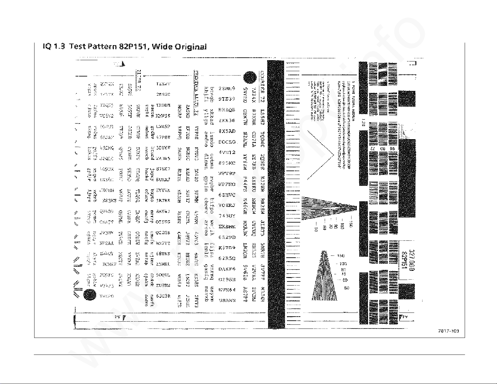
IQ 1.3 Test Pattern 82P151, Wide Original
www.printcopy.info
www.printcopy.info
IQ 1.3 3-6 Telecopier 7017 / 7017SF
6/88
Page 33
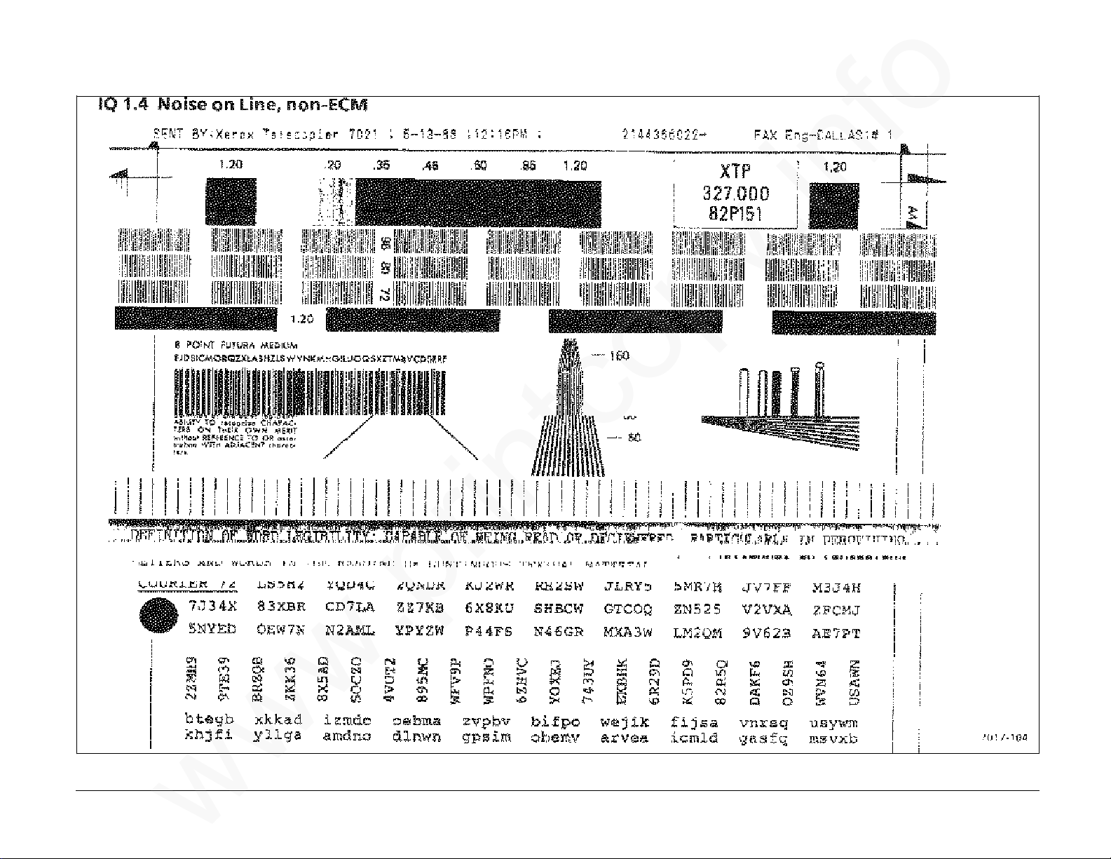
IQ 1.4 Noise on Line, non-ECM
www.printcopy.info
www.printcopy.info
Telecopier 7017 / 7017SF 3-7
12/88
IQ 1.4
Page 34
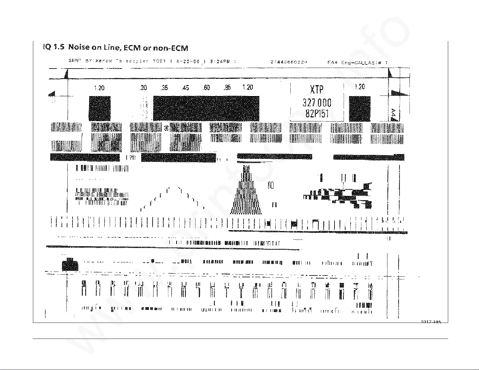
IQ 1.5 Noise on Line, ECM or non-ECM
www.printcopy.info
www.printcopy.info
IQ 1.5 3-8 Telecopier 7017 / 7017SF
12/88
Page 35
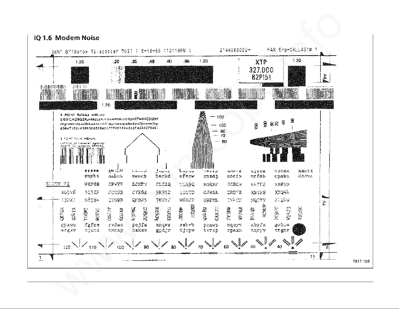
IQ 1.6 Modem Noise
www.printcopy.info
www.printcopy.info
Telecopier 7017 / 7017SF 3-9
12/88
IQ 1.6
Page 36

4. Repair / Adjustment
Introduction 4-2●
Covers and Panels
REP 1.1 Document Catch Tray Assembly 4-3●
REP 1.2 RH Cover 4-3●
REP 1.3 Coupler Cover 4-4●
REP 1.4 LH Cover 4-4●
REP 1.5 Output Tray Assembly 4-4●
REP 1.6 Rear Cover 4-5●
REP 1.7 Upper Scan Cover 4-5●
REP 1.8 Lower Scan Cover 4-5●
REP 1.9 Input Tray / Printer Cover Assembly 4-6●
REP 1.10 Input Tray Extension 4-6●
REP 1.11 Paper Side Plates 4-6●
ADF
REP 2.1 Retard Assembly 4-7●
REP 2.2 Nudger Timing Gear 4-7●
REP 2.3 Pad Assembly 4-8●
REP 2.13 Nudger Solenoid Assembly 4-14●
REP 2.14 Nudger Pawl and Nudger Pawl Spring 4-15●
Scanner
REP 3.1 Scan Position Sensor 4-15●
REP 3.2 Scan Interlock Switch 4-16●
REP 3.3 Scan Input Idler Roller 4-17●
REP 3.4 Platen Roller 4-17●
REP 3.5 Scan Output Idler Roller 4-18●
REP 3.6 Upper Scan Assembly 4-18●
REP 3.7 Video Assembly 4-19●
REP 3.8 Scan Pulley / Gear 4-20●
REP 3.9 Scan Input Drive Roller 4-20●
REP 3.10 Scan Output Drive Roller 4-21●
REP 3.11 Scan Output Drive Pulley 4-21●
REP 3.12 Scan Motor 4-22●
4. Repair / Adjustment
www.printcopy.info
www.printcopy.info
http://xww.xedoc.world.xerox.com/data/XEDOC/Central/Fax/7017/TECH/section4.htm (1 of 3) [28/09/1999 11:36:44]
Page 37

Printer
REP 4.1 Low Paper Sensor and RX: Wide Paper Sensor 4-23●
REP 4.2 Printer Jam Sensor 4-24●
REP 4.3 Printer Interlock Switch 4-24●
REP 4.4 Recording Paper Supply Indicator 4-25●
REP 4.5 Lower Paper Guide Assembly 4-26●
REP 4.6 Printer Motor Cover 4-26●
REP 4.7 Upper Printer Assembly 4-27●
REP 4.8 Printer Output Idler Rollers 4-28●
REP 4.9 Cutter 4-29●
REP 4.10 Printer Output Drive Roller 4-30●
REP 4.11 Pressure Roller Assembly 4-31●
REP 4.12 Thermal Head Assembly 4-32●
REP 4.13 Cutter Crank Arm 4-33●
REP 4.14 Cutter Cam 4-33●
REP 4.15 Printer Motor 4-34●
REP 4.16 Cutter Belt 4-35●
REP 4.17 Cutter Switch 4-35●
REP 4.18 Cutter Home Lever and / or Cutter Home Spring 4-36●
REP 4.19 Planetary Assembly 4-37●
REP 4.20 Cutter Crank Pulley 4-38●
REP 4.21 Cutter Clutch 4-38●
REP 4.22 Cutter Solenoid Assembly 4-39●
REP 4.23 Cutter Solenoid Lever 4-40●
REP 4.24 Printer Belt 4-41●
Electronics
REP 5.1 A6 Control Panel and / or Control Panel Assembly 4-42●
REP 5.2 Speaker Assembly 4-43●
REP 5.3 Fan 4-43●
REP 5.4 A8 Store & Forward PWB 4-44●
REP 5.5 A2 Main PWB 4-44●
REP 5.6 Power Supply Assembly 4-45●
REP 5.7 A3 Telephone Line Filter PWB 4-46●
4. Repair / Adjustment
www.printcopy.info
www.printcopy.info
http://xww.xedoc.world.xerox.com/data/XEDOC/Central/Fax/7017/TECH/section4.htm (2 of 3) [28/09/1999 11:36:44]
Page 38

REP 5.8 A5 Modem PWB 4-46●
REP 5.9 A10 Coupler PWB 4-47●
REP 5.10 CNC PWB Assembly 4-47●
Electronics
ADJ 5.1 Cutter Registration 4-48●
ADJ 5.2 Scan Registration 4-52●
4. Repair / Adjustment
www.printcopy.info
www.printcopy.info
http://xww.xedoc.world.xerox.com/data/XEDOC/Central/Fax/7017/TECH/section4.htm (3 of 3) [28/09/1999 11:36:44]
Page 39
Introduction
www.printcopy.info
www.printcopy.info
Overview
The Repair / Adjustment section contains the
removal, replacement, and adjustment
procedures for most components and
assemblies.
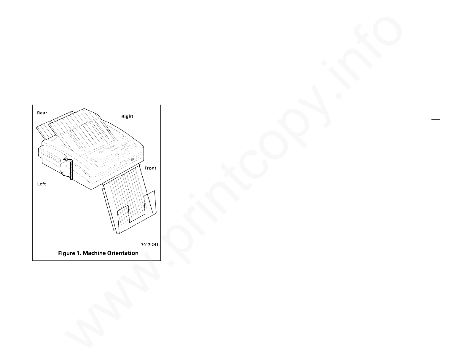
Refer to Figure 1 below in order to assist you
with references to left, right, front, and rear in
the procedures.
Organization
Section contents gives page references for all
procedures in the repair / adjustment section.
Repair contains the removal and replacement
procedures for many parts shown in the Parts
List. If a component procedure cannot be
found in this section, it usually means that
Removal or Replacement procedures are
obvious; the part or assembly is not spared
and cannot be ordered; or the part does not
need to be removed, replaced, or adjusted.
All removal replacement procedures are listed
first. They are then followed by all the
adjustment procedures.
Removal
Removal contains step-by-step removal
procedures for a specific component part or
assembly.
Illustrations are provided in some adjustments
in order to assist you with the procedures. You
should refer to the specific parts list
illustration (listed under the repair title) for
locating most components within a procedure.
Replacement
Replacement contains procedures to reinstall
or replace a component part or assembly and
those components or assemblies removed
during the removal process.
If a replacement procedure should be
completed in the exact reverse order of
removal, a generic replacement statement is
provided.
If you are in one replacement procedure and
are directed to go to another procedure to
reinstall a component, reinstall that
component then return to the original
procedure that directed you there. Do not
continue through and reinstall every
component listed in the procedure that you
referenced. The best sequence for replacing
each component removed in the original
procedure is listed in the original procedure.
Adjustment
Adjustment contains the adjustment
procedures for component parts or assemblies.
It also contains a functional check of the
component part or assembly.
Repair / Adjustment Introduction 4-2 Telecopier 7017 / 7017SF
6/88
Page 40
REP 1.1 Document Catch Tray
www.printcopy.info
www.printcopy.info
Assembly
Parts List on PL 1.1
Removal
Pull document catch tray assembly straight
forward to remove.
Replacement
REP 1.2 RH Cover
Parts List on PL 1.2
Removal
1. Remove power cord.
2. Remove document catch tray assembly
(REP 1.1).
3. Open printer.
1. Align positioning slots on document
catch tray assembly with the two
channels on base plate.
2. Press firmly towards the rear to secure.
4. Open and secure scanner.
WARNING
Do not bump the scanner after it is secured.
The scan support assembly will release and
cause the upper scan assembly to pinch you.
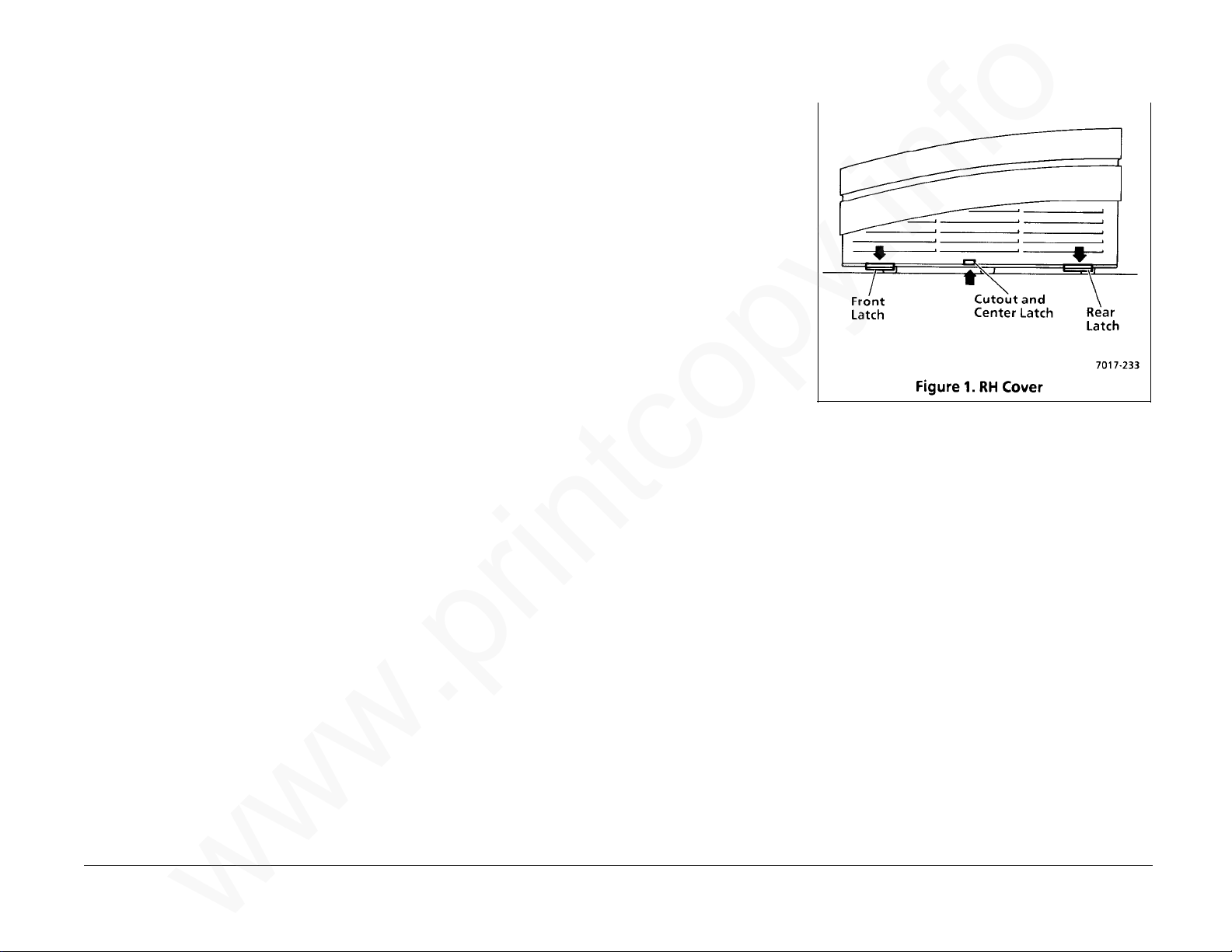
5. Remove RH cover.
NOTE: Use the cutout in the RH cover to
access and release the center latch.
a. Release the three latches (Figure 1)
from the base plate.
NOTE: Machines with serial numbers
(TBD) and above do not have the
center latch.
b. Remove the two screws securing the
RH cover to the RH frame.
c. Slide RH cover towards the right to
clear the upper scan cover and the
base plate, then pull it up and
towards the rear to clear the A8 store
& forward PWB, if installed.
Replacement
Reinstall in reverse order.
Telecopier 7017 / 7017SF 4-3
12/88
REP 1.1, 1.2
Page 41

4
www.printcopy.info
www.printcopy.info
REP 1.3 Coupler Cover
Parts List on PL 1.2
Removal
1. Remove power cord.
2. Remove document catch tray assembly
(REP 1.1).
3. USO: Remove coupler cover.
a. Disconnect handset cord from the left
side of terminal.
b. Disconnect telephone line cord from
the rear of terminal.
c. Remove the screw securing coupler
cover.
d. Slide coupler cover towards the rear
until it stops, then rotate bottom
edge towards the left and down to
remove.
Replacement
1. Align upper locking tab on coupler cover
with the rear of cutout on LH cover.
2. Reinstall in reverse order.
REP 1.4 LH Cover
Parts List on PL 1.2
Removal
1. Remove power cord.
2. Remove document catch tray assembly
(REP 1.1).
3. Remove coupler cover (REP 1.3).
4. Open printer.
5. Open and secure scanner.
WARNING
Do not bump the scanner after it is secured.
The scan support assembly will release and
cause the upper scan assembly to pinch you.
6. Remove LH cover.
a. Release two latches from the base
plate.
b. Remove the two screws securing the
LH cover to the LH frame.
c. Pull LH cover towards the left to clear
the upper scan cover and the base
plate, then pull it straight up to clear
speaker assembly.
Replacement
Reinstall in reverse order.
REP 1.5 Output Tray Assembly
Parts List on PL 1.1
Removal
1. Remove document catch tray assembly
(REP 1.1).
2. Remove output tray assembly.
a. Lift output tray assembly straight up
until top front ridge touches base
frame.
b. Rotate rear of output tray assembly
forward, then slide output tray
assembly backward to remove.
Replacement
1. Align front lip of output tray assembly
with opening in rear of base frame.
2. Position output tray assembly parallel to
input tray extension.
3. Insert front of output tray assembly fully
into opening.
4. Rotate rear of output tray assembly
forward while pressing down on front of
output tray assembly until output tray
assembly slips into a secured position.
5. Press output tray assembly down to
ensure it is fully seated.
6. Reinstall document catch tray assembly
(REP 1.1).
REP 1.3, 1.4, 1.5 4-4 Telecopier 7017 / 7017SF
6/88
Page 42

REP 1.6 Rear Cover
www.printcopy.info
www.printcopy.info
REP 1.7 Upper Scan Cover
REP 1.8 Lower Scan Cover
Parts List on PL 1.2
Removal
1. Remove power cord.
2. Remove document catch tray assembly
(REP 1.1).
3. Remove output tray assembly (REP 1.5).
4. Remove rear cover.
a. Remove the two screws securing rear
cover to the power supply housing.
b. Rotate the top edge of rear cover
towards the rear to clear printer
output drive roller.
c. Lift rear cover up and out of cutouts
in power supply housing.
Replacement
Reinstall in reverse order.
Parts List on PL 1.2
Removal
1. Remove power cord.
2. Remove document catch tray assembly
(REP 1.1).
3. Remove coupler cover (REP 1.3).
4. Remove LH cover (REP 1.4).
5. Remove scan support assembly.
6. Remove control panel assembly (REP 5.1).
7. Remove upper scan cover.
a. Remove the two screws securing
upper scan cover.
b. Remove upper scan cover.
Replacement
1. Position the two locating pegs on upper
scan cover into the two locating holes.
2. Ensure W4 wire harness is not pinched by
the upper scan cover.
3. Reinstall in reverse order.
Parts List on PL 1.2
Removal
1. Remove power cord.
2. Remove document catch tray assembly
(REP 1.1).
3. Open and secure scanner.
WARNING
Do not bump the scanner after it is secured.
The scan support assembly will release and
cause the upper scan assembly to pinch you.
4. Remove lower scan cover.
a. Release the latch securing lower scan
cover to LH frame.
b. Release the latch securing lower scan
cover to RH frame.
c. Pull lower scan cover gently forward
to clear video assembly, then raise it
to clear lip of base plate.
Replacement
Reinstall in reverse order.
Telecopier 7017 / 7017SF 4-5
6/88
REP 1.6, 1.7, 1.8
Page 43

REP 1.9 Input Tray / Printer Cover
www.printcopy.info
www.printcopy.info
Assembly
Parts List on PL 1.2
Removal
1. Remove power cord.
2. Remove document catch tray assembly
(REP 1.1).
3. Open printer.
4. Remove input tray / printer cover
assembly.
a. Loosen the two screws securing the
input tray / printer cover assembly to
the upper printer frame.
b. Lift rear of input tray / printer cover
assembly to clear screws, then slide it
towards the left and rear to clear
printer release lever and the two
cutouts on the upper printer frame.
5. If replacing input tray / printer cover
assembly, remove input tray extension
(REP 1.10).
Replacement
Reinstall in reverse order.
REP 1.10 Input Tray Extension
Parts List on PL 1.2
Removal
1. Remove document catch tray assembly
(REP 1.1).
2. Remove input tray extension.
a. Rotate input tray extension to a
vertical position.
b. Press bottom center of input tray
extension until pivot pins release
from locating holes.
Replacement
Reinstall in reverse order.
REP 1.11 Paper Side Plates
Parts List on PL 1.3
Removal
1. Remove document catch tray assembly
(REP 1.1).
2. Open printer.
3. Remove paper side plates.
a. Remove recording paper.
b. Remove paper side plate/plates.
Replacement
1. Reinstall paper side plate in the LH
locating slots of base frame so that the
correct paper size is printed facing the RH
frame.
2. Reinstall paper side plate in the RH
locating slots of base frame so that the
correct paper size is printed facing the LH
frame.
3. Reinstall recording paper.
4. Close printer.
5. Reinstall document catch tray assembly
(REP 1.1).
REP 1.9, 1.10, 1.11 4-6 Telecopier 7017 / 7017SF
6/88
Page 44

REP 2.1 Retard Assembly
www.printcopy.info
www.printcopy.info
Parts List on PL 2.1
Removal
1. Remove power cord.
2. Remove document catch tray assembly
(REP 1.1).
f. Reinstall bearing # 6 in LH frame and
secure with KL-ring.
g. Reinstall nudger arm spring in
nudger arm.
2. Reinstall remaining components in
reverse order.
REP 2.2 Nudger Timing Gear
Parts List on PL 2.1
Removal
1. Remove power cord.
2. Remove document catch tray assembly
(REP 1.1).
3. Remove coupler cover (REP 1.3).
4. Remove LH cover (REP 1.4).
5. Remove retard assembly. (Figure 1)
a. Ensure nudger clutch is at home
position (cutouts aligned).
b. Remove nudger arm spring from
nudger arm.
c. Remove KL-ring securing LH bearing
#6.
d. Remove LH bearing #6 from LH
frame.
e. Remove retard assembly.
f. Remove RH bearing #6.
Replacement
1. Reinstall retard assembly
a. Ensure nudger clutch is at home
position.
b. Reinstall RH bearing #6 on retard
assembly.
c. Reinstall RH bearing #6 and retard
assembly in RH frame.
3. Remove coupler cover (REP 1.3).
4. Remove LH cover (REP 1.4).
5. Remove nudger timing gear.
a. Remove KL-ring securing nudger
timing gear.
b. Remove nudger timing gear.
Replacement
1. Reinstall nudger timing gear.
a. Rotate nudger timing gear to align
cutout on gear with cutout on
nudger clutch.
b. Reinstall nudger timing gear and
secure with KL-ring.
2. Reinstall remaining components in
reverse order.
Telecopier 7017 / 7017SF 4-7
d. Position paper weights in cutouts in
nudger arm, then position nudger
arm on top of the nudger roller.
e. Rotate retard assembly to align
cutout on nudger timing gear with
cutout on nudger clutch.
12/88
REP 2.1, 2.2
Page 45

REP 2.3 Pad Assembly
www.printcopy.info
www.printcopy.info
Parts List on PL 2.1
Removal
1. Remove power cord.
2. Remove document catch tray assembly
(REP 1.1).
3. Remove coupler cover (REP 1.3).
4. Remove LH cover (REP 1.4).
5. Remove retard assembly (REP 2.1).
6. Remove pad assembly. (Figure 1)
a. Remove E-ring on right end of retard
assembly.
b. Remove E-ring securing RH cam /
stopper.
c. Remove RH cam / stopper.
d. Remove dowel pin.
e. Remove E-ring securing pad shaft.
f. Remove pad shaft, two paper
weights, and nudger arm.
Replacement
NOTE: Check alignment of components
carefully during reinstallation.
Reinstall in reverse order.
REP 2.3 4-8 Telecopier 7017 / 7017SF
g. Remove E-ring securing pad
assembly.
h. Remove pad assembly, LH and RH
retard springs, and spring spacer.
i. Remove LH and RH hooks if installed.
12/88
Page 46

REP 2.12 ADF Belt (continued)
www.printcopy.info
www.printcopy.info
Replacement
1. Reinstall ADF belt with dot (on edge of
belt) towards the RH frame.
2. Reinstall remaining components in
reverse order.
3. Ensure ADF belt is properly seated in the
alignment grooves on both the ADF drive
clutch and the ADF idler roller.
REP 2.13 Nudger Solenoid
Assembly
Parts List on PL 2.2
Removal
1. Remove power cord.
2. Remove document catch tray assembly
(REP 1.1).
3. Remove RH cover (REP 1.2).
4. Remove coupler cover (REP 1.3).
Replacement
1. If the nudger solenoid assembly was
replaced, discard any spring and nylon
washer with the old solenoid assembly.
NOTE: Document feed problems can occur if
the spring and nylon washer on the solenoid
plunger are reinstalled when nudger solenoid
assembly is replaced.
2. Reinstall nudger solenoid assembly.
a. Rotate nudger pawl towards the rear
to reinstall nudger solenoid plunger.
5. Remove LH cover (REP 1.4).
6. If installed, remove A8 store & forward
PWB (REP 5.4).
7. Remove A2 main PWB (REP 5.5).
8. Remove power supply assembly (REP 5.6).
9. Remove CNC PWB assembly (REP 5.10).
10.Remove nudger solenoid assembly.
(Figure 1)
a. Remove screw on top of nudger
solenoid, then remove solenoid.
b. Rotate nudger pawl towards the rear
to remove nudger solenoid plunger.
b. If nudger solenoid assembly is being
reinstalled and spring and nylon
washer were removed during
removal procedures, reposition
spring and nylon washer on plunger.
c. Position nudger solenoid on the
plunger, then on the locating pin.
d. Bias front of nudger solenoid
assembly toward right and rear of
nudger solenoid assembly toward left
as shown in Figure 1.
e. Secure nudger solenoid assembly
with the screw.
3. Reinstall remaining components in
reverse order.
REP 2.12, 2.13 4-14 Telecopier 7017 / 7017SF
12/88
Page 47

REP 2.14 Nudger Pawl and
www.printcopy.info
www.printcopy.info
Nudger Pawl Spring
Parts List on PL 2.2
Removal
1. Remove power cord.
2. Remove document catch tray assembly
(REP 1.1).
3. Remove RH cover (REP 1.2).
4. Remove coupler cover (REP 1.3).
5. Remove LH cover (REP 1.4).
6. If installed, remove A8 store & forward
PWB (REP 5.4).
7. Remove A2 main PWB (REP 5.5).
8. Remove power supply assembly (REP 5.6).
9. Remove CNC PWB assembly (REP 5.10).
10. Remove nudger solenoid assembly (REP
2.13).
11.Remove nudger pawl and nudger pawl
spring. (Figure 1)
Replacement
1. Reinstall in reverse order.
2. Check that spring is positioned in the
detent on the locating tab on the LH
frame.
REP 3.1 Scan Position Sensor
Parts List on PL 3.1
Removal
1. Remove power cord.
2. Remove document catch tray assembly
(REP 1.1).
3. Remove control panel assembly (REP 5.1).
4. Remove upper scan cover (REP 1.7).
5. Remove scan position sensor.
a. Remove scan sensor bracket from
scan input idler roller.
b. Remove scan position sensor from
scan sensor bracket.
c. Disconnect J405 at scan position
sensor.
Continued
Telecopier 7017 / 7017SF 4-15
a. Rotate nudger pawl away from
nudger clutch.
b. Remove nudger pawl spring from LH
frame.
c. Remove nudger pawl and nudger
pawl spring.
12/88
REP 2.14, 3.1
Page 48

REP 3.1 Scan Position Sensor
www.printcopy.info
www.printcopy.info
(continued)
Replacement
1. Connect J405.
2. Reinstall scan position sensor on scan
sensor bracket.
3. Position the sensor actuator in cutout on
upper scan frame.
4. Reinstall scan sensor bracket.
5. Route wires around guide fingers and
cutout on retard stop bracket and
through cable clamp (Figure 1).
6. Reinstall remaining components in
reverse order.
REP 3.2 Scan Interlock Switch
Parts List on PL 3.1
Removal
1. Remove power cord.
2. Remove document catch tray assembly
(REP 1.1).
3. Remove RH cover (REP 1.2).
4. Remove coupler cover (REP 1.3).
5. Remove LH cover (REP 1.4).
6. If installed, remove A8 store & forward
PWB (REP 5.4).
7. Remove A2 main PWB (REP 5.5).
8. Remove power supply assembly (REP 5.6).
9. Remove CNC PWB assembly (REP 5.10).
10. Remove scan interlock switch.
a. Remove scan interlock switch harness
from cable clamp.
b. Remove screw securing scan interlock
switch.
Replacement
1. Reposition scan interlock switch on
locating point and to the rear of the tab
on the LH frame.
2. Reinstall screw securing scan interlock
switch.
CAUTION
Position scan interlock switch harness away
from scan output drive belt.
3. Reinstall scan interlock switch harness in
cable clamp.
4. Reinstall remaining components in
reverse order.
REP 3.1, 3.2 4-16 Telecopier 7017 / 7017SF
c. Remove scan interlock switch.
12/88
Page 49
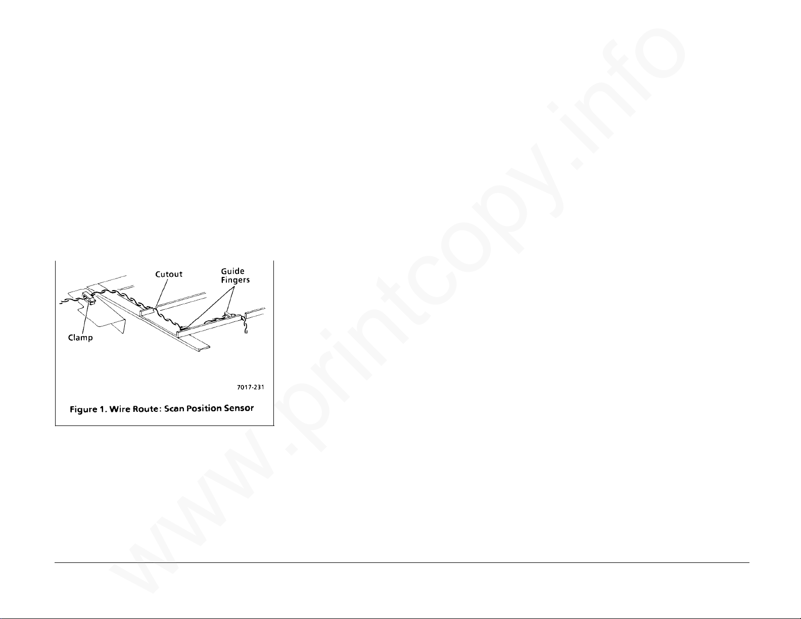
REP 3.1 Scan Position Sensor
www.printcopy.info
www.printcopy.info
(continued)
Replacement
1. Connect J405.
2. Reinstall scan position sensor on scan
sensor bracket.
3. Position the sensor actuator in cutout on
upper scan frame.
4. Reinstall scan sensor bracket.
5. Route wires around guide fingers and
cutout on retard stop bracket and
through cable clamp (Figure 1).
6. Reinstall remaining components in
reverse order.
REP 3.2 Scan Interlock Switch
Parts List on PL 3.1
Removal
1. Remove power cord.
2. Remove document catch tray assembly
(REP 1.1).
3. Remove RH cover (REP 1.2).
4. Remove coupler cover (REP 1.3).
5. Remove LH cover (REP 1.4).
6. If installed, remove A8 store & forward
PWB (REP 5.4).
7. Remove A2 main PWB (REP 5.5).
8. Remove power supply assembly (REP 5.6).
9. Remove CNC PWB assembly (REP 5.10).
10. Remove scan interlock switch.
a. Remove scan interlock switch harness
from cable clamp.
b. Remove screw securing scan interlock
switch.
Replacement
1. Reposition scan interlock switch on
locating point and to the rear of the tab
on the LH frame.
2. Reinstall screw securing scan interlock
switch.
CAUTION
Position scan interlock switch harness away
from scan output drive belt.
3. Reinstall scan interlock switch harness in
cable clamp.
4. Reinstall remaining components in
reverse order.
REP 3.1, 3.2 4-16 Telecopier 7017 / 7017SF
c. Remove scan interlock switch.
12/88
Page 50
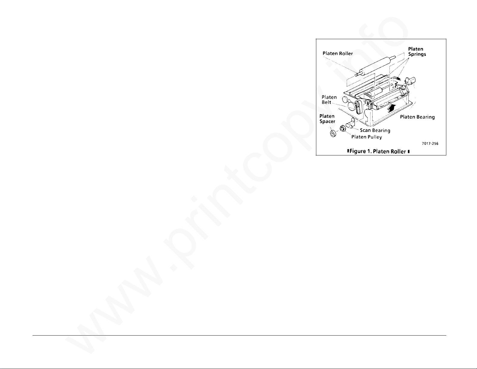
REP 3.3 Scan Input Idler Roller
www.printcopy.info
www.printcopy.info
REP 3.4 Platen Roller
Parts List on PL 3.2
Removal
1. Remove power cord.
2. Remove document catch tray assembly
(REP 1.1).
3. Remove control panel assembly (REP 5.1).
4. Remove upper scan cover (REP 1.7).
5. Remove scan input idler roller.
a. Remove scan sensor bracket from
scan input idler roller.
b. Remove E-ring securing platen pulley
on scan input idler roller shaft.
c. Remove platen pulley and platen
belt.
d. Remove two scan idler springs from
scan input idler roller.
e. Remove two upper scan bearings
from scan input idler roller.
f. Remove scan input idler roller.
Replacement
Parts List on PL 3.2
Removal
1. Remove power cord.
2. Remove document catch tray assembly
(REP 1.1).
3. Remove control panel assembly (REP 5.1).
4. Remove upper scan cover (REP 1.7).
5. Remove platen roller. (Figure 1)
a. Remove E-ring securing platen
spacer.
b. Remove platen spacer.
c. Remove platen belt.
d. Remove platen pulley from platen
roller.
e. Remove the two platen springs.
f. Remove upper scan bearing from
platen roller.
g. Remove RH platen bearing.
h. Remove platen roller.
Replacement
Reinstall in reverse order.
Reinstall in reverse order.
Telecopier 7017 / 7017SF 4-17
12/88
REP 3.3, 3.4
Page 51

REP 3.5 Scan Output Idler Roller
www.printcopy.info
www.printcopy.info
Parts List on PL 3.2
Removal
1. Remove power cord.
2. Remove document catch tray assembly
(REP 1.1).
3. Remove control panel assembly (REP 5.1).
4. Remove upper scan cover (REP 1.7).
5. Remove scan output idler roller.
a. Remove two scan idler springs from
scan output idler roller.
b. Remove two upper scan bearings
from scan output idler roller.
c. Remove scan output idler roller.
REP 3.6 Upper Scan Assembly
Parts List on PL 3.2
Removal
1. Remove power cord.
2. Remove document catch tray assembly
(REP 1.1).
3. Remove RH cover (REP 1.2).
4. Remove coupler cover (REP 1.3).
5. Remove LH cover (REP 1.4).
6. Remove upper scan assembly.
a. Remove screw securing ground wire
to LH frame.
b. Disconnect J110 and J111 at A0 CNC
PWB.
Replacement
NOTE: During reinstallation, ensure proper
alignment by:
• Rotating upper scan assembly towards
the rear of terminal.
• Ensuring both scan pivot springs are
properly positioned in the cutouts in the
upper scan frame and on top of the
locating tabs on the LH and RH frame
(Figure 1). The spring coils can bind
between the upper scan frame and the
scan pivot shaft.
Reinstall in reverse order.
Replacement
Reinstall in reverse order.
c. Remove wire harnesses from cable
clamp.
d. Release nudger arm spring from the
scan pivot shaft.
e. Remove LH E-ring from scan pivot
shaft.
f. Remove LH scan pivot bearing.
g. Remove scan pivot springs while
removing the scan pivot shaft.
h. Remove upper scan assembly.
REP 3.5, 3.6 4-18 Telecopier 7017 / 7017SF
12/88
Page 52
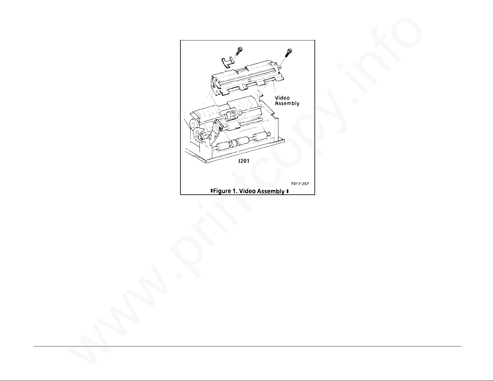
REP 3.7 Video Assembly
www.printcopy.info
www.printcopy.info
Parts List on PL 3.3
Removal
CAUTION
Follow electrostatic discharge precautions
(Section 6). Static electricity can damage this
component.
1. Remove power cord.
2. Remove document catch tray assembly
(REP 1.1).
3. Remove RH cover (REP 1.2).
4. Remove coupler cover (REP 1.3).
5. Remove LH cover (REP 1.4).
6. Remove video assembly. (Figure 1)
a. Remove screw securing video
assembly and scan belt bracket to LH
frame.
b. Remove screw securing video
assembly to RH frame.
c. Lift video assembly to access W11
wire harness.
Telecopier 7017 / 7017SF 4-19
d. Disconnect J201 from video assembly.
e. Remove video assembly.
Replacement
Reinstall in reverse order.
12/88
REP 3.7
Page 53

REP 3.8 Scan Pulley/Gear
www.printcopy.info
www.printcopy.info
Parts List on PL 3.3
Replacement
Reinstall in reverse order.
REP 3.9 Scan Input Drive Roller
Parts List on PL 3.3
Removal
1. Remove power cord.
2. Remove document catch tray assembly
(REP 1.1).
3. Remove coupler cover (REP 1.3).
4. Remove LH cover (REP 1.4).
5. Remove scan pulley/gear. (Figure 1)
a. Remove scan output drive belt.
b. Remove E-ring from scan input drive
roller.
c. Remove scan input drive belt.
d. Remove scan pulley/gear.
Removal
1. Remove power cord.
2. Remove document catch tray assembly
(REP 1.1).
3. Remove RH cover (REP 1.2).
4. Remove coupler cover (REP 1.3).
5. Remove LH cover (REP 1.4).
6. Remove video assembly (REP 3.7).
7. Remove scan pulley/gear (REP 3.8).
8. Remove scan input drive roller.
a. Remove E-ring and plastic bearing
from LH frame.
b. Remove E-ring and brass bearing
from RH frame.
c. Remove scan input drive roller.
d. Remove bearings.
Replacement
Reinstall in reverse order.
REP 3.8, 3.9 4-20 Telecopier 7017 / 7017SF
12/88
Page 54

REP 3.10 Scan Output Drive
www.printcopy.info
www.printcopy.info
Roller
REP 3.11 Scan Output Drive
Pulley
Parts List on PL 3.3
Removal
1. Remove power cord.
2. Remove document catch tray assembly
(REP 1.1).
3. Remove RH cover (REP 1.2).
4. Remove coupler cover (REP 1.3).
5. Remove LH cover (REP 1.4).
6. Remove video assembly (REP 3.7).
7. Remove scan output drive roller.
a. Remove scan output drive belt.
b. Remove the three E-rings on the scan
output drive roller.
c. Remove scan output drive roller and
brass bearing from RH frame.
d. Remove scan output drive pulley
from scan output drive roller.
e. Remove scan output drive roller and
plastic bearing from LH frame.
Parts List on PL 3.3
Removal
1. Remove power cord.
2. Remove document catch tray assembly
(REP 1.1).
3. Remove coupler cover (REP 1.3).
4. Remove LH cover (REP 1.4).
5. Remove speaker assembly (REP 5.2).
6. Remove scan output drive pulley.
a. Remove scan output drive belt.
b. Remove E-ring securing scan output
drive pulley.
c. Remove scan output drive pulley.
Replacement
Reinstall in reverse order.
Replacement
Reinstall in reverse order.
Telecopier 7017 / 7017SF 4-21
f. Remove bearings from scan output
drive roller.
12/88
REP 3.10, 3.11
Page 55
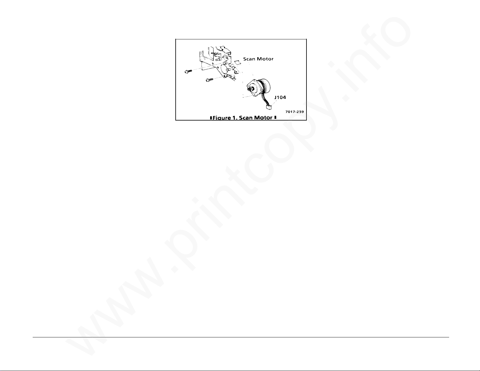
REP 3.12 Scan Motor
www.printcopy.info
www.printcopy.info
Parts List on PL 3.3
Removal
1. Remove power cord.
2. Remove document catch tray assembly
(REP 1.1).
3. Remove RH cover (REP 1.2).
4. Remove coupler cover (REP 1.3).
5. Remove LH cover (REP 1.4).
6. If installed, remove A8 store and forward
PWB.
7. Remove A2 main PWB (REP 5.5).
8. Remove power supply assembly (REP 5.6).
9. Remove CNC PWB assembly (REP 5.10).
10.Remove scan motor. (Figure 1)
a. Remove scan input drive belt from
scan motor.
b. Remove the two screws from the scan
motor.
c. Remove scan motor through the RH
frame.
Replacement
NOTE: Replacement motors have both J104
and J115 marked on the connector. Scan
motor connector should be marked as J104.
1. If scan motor was replaced, delete J115
on the connector.
2. Reinstall in reverse order.
REP 3.12 4-22 Telecopier 7017 / 7017SF
12/88
Page 56
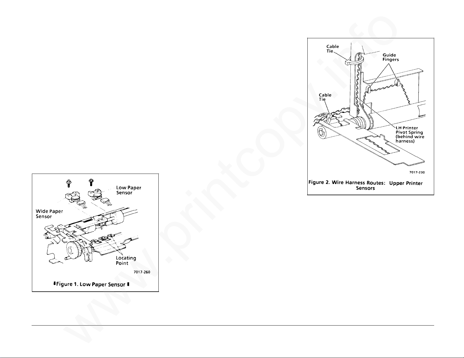
REP 4.1 Low Paper Sensor and
www.printcopy.info
www.printcopy.info
RX: Wide Paper Sensor
Replacement
1. Reposition sensor on locating point.
Parts List on PL 4.1
Removal
1. Remove power cord.
2. Remove document catch tray assembly
(REP 1.1).
3. Remove input tray / printer cover
assembly (REP 1.9).
4. Remove sensor. (Figure 1)
a. Disconnect jack from sensor:
J408 low paper sensor
J409 RX: wide paper sensor
b. Remove screw securing sensor.
c. Remove sensor.
2. Reinstall screw securing sensor.
3. Connect jack:
J408 low paper sensor
J409 RX: wide paper sensor
4. Ensure wire harnesses are properly
routed through guide fingers. (Figure 2)
5. Reinstall remaining components in
reverse order.
Telecopier 7017 / 7017SF 4-23
12/88
REP 4.1
Page 57

REP 4.2 Printer Jam Sensor
www.printcopy.info
www.printcopy.info
REP 4.3 Printer Interlock Switch
Parts List on PL 4.1
Removal
1. Remove power cord.
2. Remove document catch tray assembly
(REP 1.1).
3. Remove input tray / printer cover
assembly (REP 1.9).
4. Remove jam sensor bracket.
a. Remove screw securing jam sensor
bracket.
b. Remove jam sensor bracket.
5. Remove printer jam sensor. (Figure 1)
a. Disconnect J406 at printer jam sensor.
b. Release locking tabs, then remove
printer jam sensor.
Replacement
1. Reinstall sensor on jam sensor bracket.
2. Connect J406.
3. Ensure W6 wire harness is properly
routed through guide fingers. (Figure 1
of REP 4.1)
Parts List on PL 4.1
Removal
1. Remove power cord.
2. Remove document catch tray assembly
(REP 1.1).
3. Remove coupler cover (REP 1.3).
4. Remove LH cover (REP 1.4).
5. Remove printer interlock switch.
a. Disconnect J112 at A0 CNC PWB.
b. Remove printer interlock switch
harness from twist tie.
c. Remove screw securing printer
interlock switch.
d. Remove printer interlock switch.
Replacement
1. Reposition printer interlock switch on the
locating point and to rear of the tab on
the LH frame.
2. Reinstall screw securing printer interlock
switch.
3. Reinstall remaining components in
reverse order.
REP 4.2, 4.3 4-24 Telecopier 7017 / 7017SF
4. Reposition jam sensor bracket in locating
slot on upper printer frame and on
locating point, then secure with screw.
5. Reinstall remaining components in
reverse order.
12/88
Page 58
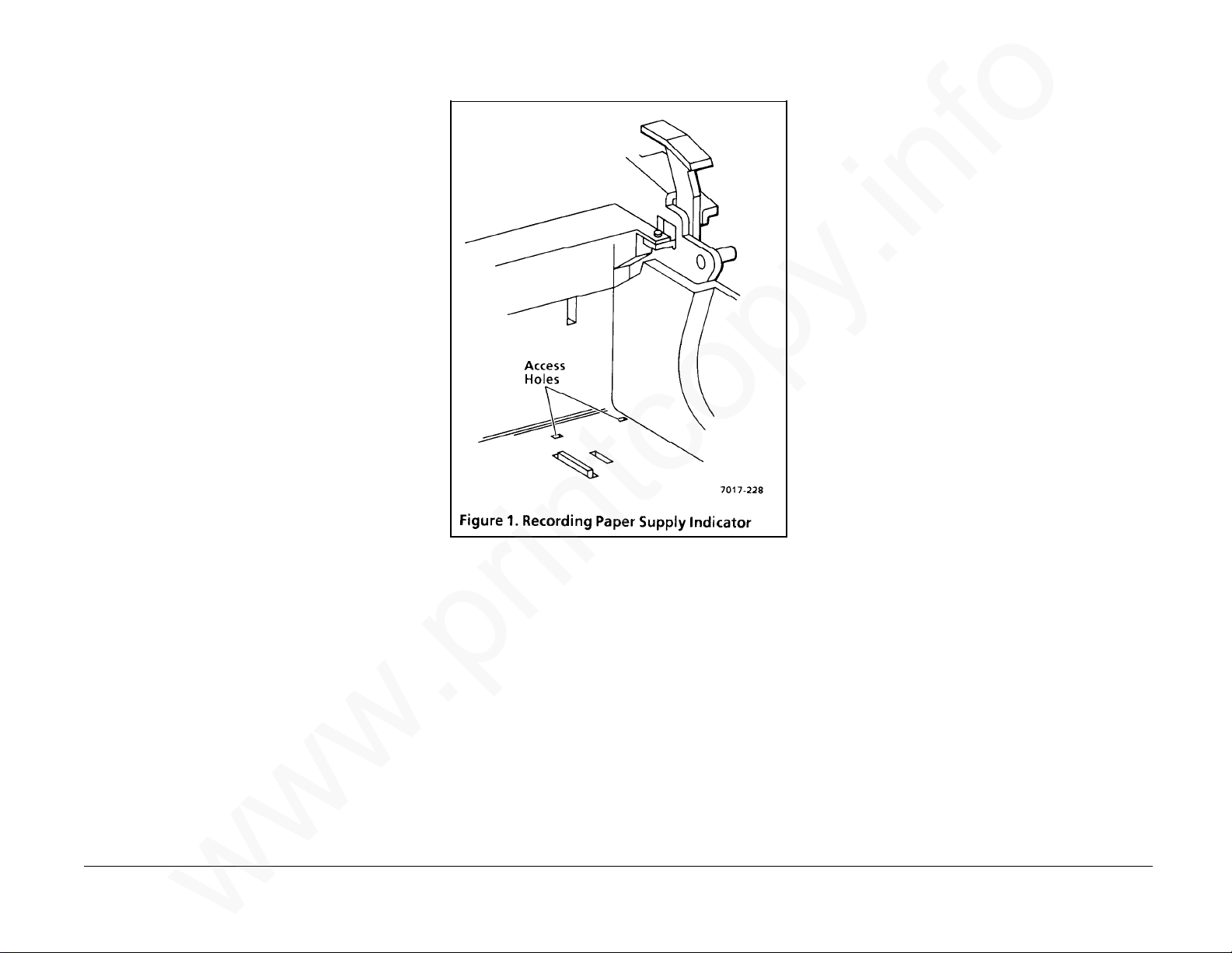
REP 4.4 Recording Paper Supply
www.printcopy.info
www.printcopy.info
Indicator
Parts List on PL 4.3
Removal
1. Remove power cord.
2. Remove document catch tray assembly
(REP 1.1).
3. Remove RH cover (REP 1.2).
4. If installed, remove A8 store & forward
PWB (REP 5.4).
5. Remove the recording paper.
6. Remove the recording paper supply
indicator.
a. Remove indicator spring from the RH
frame.
b. Press a small screwdriver through the
access holes in the base frame (Figure
1) to release the recording paper
supply indicator.
Replacement
1. Reinstall the recording paper supply
indicator.
2. Reinstall the indicator spring.
3. Check for the following:
• The recording paper supply
indicator is positioned at rear of
RH frame cutout.
• Both ends of shaft on the
recording paper supply indicator
are secured in the base frame.
• Indicator spring is positioned in
detent on the locating tab on the
RH frame.
4. Reinstall remaining components in
reverse order.
Telecopier 7017 / 7017SF 4-25
12/88
REP 4.4
Page 59

REP 4.5 Lower Paper Guide
www.printcopy.info
www.printcopy.info
Assembly
Parts List on PL 4.3
Removal
1. Remove power cord.
2. Remove document catch tray assembly
(REP 1.1).
3. Open printer.
4. Remove recording paper.
5. Remove lower paper guide assembly.
a. Remove the screw securing left side
of lower paper guide assembly.
NOTE: Set this screw (from left side of lower
paper guide assembly) aside, it is longer than
the other black screws.
b. Remove the screw securing right side
of lower paper guide assembly.
c. Remove lower paper guide assembly.
Replacement
1. Position three locating tabs in cutouts in
base frame.
REP 4.6 Printer Motor Cover
Parts List on PL 4.3
Removal
1. Remove power cord.
2. Remove document catch tray assembly
(REP 1.1).
3. Open printer.
4. Remove recording paper.
5. Remove lower paper guide assembly (REP
4.5).
6. Remove printer motor cover.
a. Remove printer motor cover from LH
frame.
b. Remove printer motor cover.
Replacement
1. Position two locating tabs in cutouts in
base frame.
2. Position locating pin in LH frame.
3. Reinstall remaining components in
reverse order.
2. Reinstall remaining components in
REP 4.5, 4.6 4-26 Telecopier 7017 / 7017SF
reverse order.
12/88
Page 60

REP 4.7 Upper Printer Assembly
www.printcopy.info
www.printcopy.info
Parts List on PL 4.1
Removal
Replacement
NOTE: Terminals without Tag/MOD 3 have
brass and black washers which must be
reinstalled:
1. Remove power cord.
2. Remove document catch tray assembly
(REP 1.1).
3. Remove RH cover (REP 1.2).
4. Remove coupler cover (REP 1.3).
5. Remove LH cover (REP 1.4).
6. Remove upper printer assembly. (Figure
1)
a. Cut cable tie.
b. Disconnect J114, J116, and RX: J117
from A0 CNC PWB.
c. Remove W6, W7, and RX: W8 wire
harnesses from cable clamp.
d. Remove E-rings at both ends of
printer pivot shaft.
e. Remove LH and RH printer pivot
bearings.
f. Remove printer pivot shaft from RH
frame.
g. Remove printer pivot shaft from LH
frame.
• a brass washer between the LH frame
and the LH printer pivot spring,
• a brass washer between the RH frame
and the RH printer cam bearing, and
• a black washer between the LH spring
and the LH bearing.
1. Position printer pivot shaft in LH frame.
2. Position printer pivot shaft in RH frame.
Continued
Telecopier 7017 / 7017SF 4-27
h. Remove upper printer assembly.
12/88
REP 4.7
Page 61

REP 4.7 Upper Printer Assembly
www.printcopy.info
www.printcopy.info
(continued)
CAUTION
Route LH printer pivot spring behind the wire
harness.
3. Ensure LH printer pivot spring (black) is
properly seated in both frame cutouts
and wire harnesses are properly routed.
(Figure 2)
4. Ensure RH printer pivot spring (brass) is
properly seated in both frame cutouts.
5. Reinstall and/or replace remaining
components in reverse order. (Figure 3)
REP 4.8 Printer Output Idler
Rollers
Parts List on PL 4.1
Removal
1. Remove power cord.
2. Remove document catch tray assembly
(REP 1.1).
3. Remove RH cover (REP 1.2).
4. Remove coupler cover (REP 1.3).
5. Remove LH cover (REP 1.4).
6. Remove upper printer assembly (REP 4.7).
7. Remove printer output idler rollers.
a. Remove all E-rings securing printer
output idler rollers.
b. Remove E-ring securing LH printer
cam bearing.
c. Remove LH printer cam bearing and
LH printer pivot spring.
d. Slide printer pivot shaft to the right
to remove printer output idler rollers.
REP 4.7, 4.8 4-28 Telecopier 7017 / 7017SF
Continued
12/88
Page 62
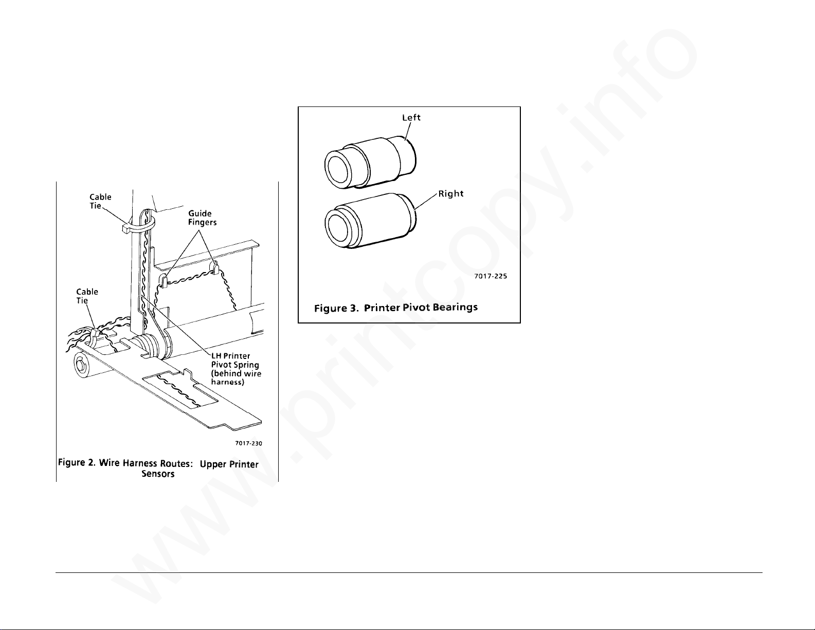
REP 4.7 Upper Printer Assembly
www.printcopy.info
www.printcopy.info
(continued)
CAUTION
Route LH printer pivot spring behind the wire
harness.
3. Ensure LH printer pivot spring (black) is
properly seated in both frame cutouts
and wire harnesses are properly routed.
(Figure 2)
4. Ensure RH printer pivot spring (brass) is
properly seated in both frame cutouts.
5. Reinstall and/or replace remaining
components in reverse order. (Figure 3)
REP 4.8 Printer Output Idler
Rollers
Parts List on PL 4.1
Removal
1. Remove power cord.
2. Remove document catch tray assembly
(REP 1.1).
3. Remove RH cover (REP 1.2).
4. Remove coupler cover (REP 1.3).
5. Remove LH cover (REP 1.4).
6. Remove upper printer assembly (REP 4.7).
7. Remove printer output idler rollers.
a. Remove all E-rings securing printer
output idler rollers.
b. Remove E-ring securing LH printer
cam bearing.
c. Remove LH printer cam bearing and
LH printer pivot spring.
d. Slide printer pivot shaft to the right
to remove printer output idler rollers.
REP 4.7, 4.8 4-28 Telecopier 7017 / 7017SF
Continued
12/88
Page 63

REP 4.8 Printer Output Idler
www.printcopy.info
www.printcopy.info
Rollers (continued)
Replacement
1. Reinstall printer output idler rollers.
NOTE: Reinstall the idler rollers with the
spokes on the left side and the smooth hub on
the right side.
a. Slide printer pivot shaft to the left to
reposition and hold printer output
idler rollers in upper printer frame.
b. Reposition printer pivot shaft
through upper printer frame.
c. Reinstall LH printer cam bearing and
secure with E-ring.
d. Reinstall all E-rings securing printer
output idler rollers.
e. Reposition LH printer pivot spring on
printer cam bearing.
2. Reinstall remaining components in
reverse order.
REP 4.9 Cutter
Parts List on PL 4.2
Removal
1. Remove power cord.
2. Remove document catch tray assembly
(REP 1.1).
3. Remove RH cover (REP 1.2).
4. Remove coupler cover (REP 1.3).
5. Remove LH cover (REP 1.4).
6. Remove upper printer assembly (REP 4.7).
7. Remove the cutter. (Figure 1)
a. Remove screw securing the cutter
cam.
b. Remove the two screws securing the
cutter.
WARNING
Do not handle the pivoting blade on the
cutter. It has a sharp edge.
c. Remove the cutter.
Replacement
WARNING
Do not handle the pivoting blade on the
cutter. It has a sharp edge.
Telecopier 7017 / 7017SF 4-29
1. Reposition cutter.
2. Bias cutter to rear and secure with screws.
3. Reinstall remaining components in
reverse order.
12/88
REP 4.8, 4.9
Page 64
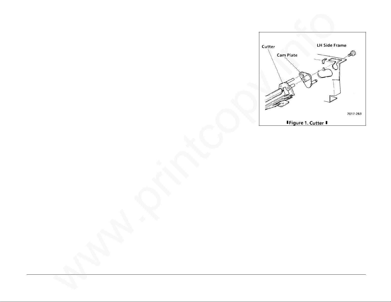
REP 4.8 Printer Output Idler
www.printcopy.info
www.printcopy.info
Rollers (continued)
Replacement
1. Reinstall printer output idler rollers.
NOTE: Reinstall the idler rollers with the
spokes on the left side and the smooth hub on
the right side.
a. Slide printer pivot shaft to the left to
reposition and hold printer output
idler rollers in upper printer frame.
b. Reposition printer pivot shaft
through upper printer frame.
c. Reinstall LH printer cam bearing and
secure with E-ring.
d. Reinstall all E-rings securing printer
output idler rollers.
e. Reposition LH printer pivot spring on
printer cam bearing.
2. Reinstall remaining components in
reverse order.
REP 4.9 Cutter
Parts List on PL 4.2
Removal
1. Remove power cord.
2. Remove document catch tray assembly
(REP 1.1).
3. Remove RH cover (REP 1.2).
4. Remove coupler cover (REP 1.3).
5. Remove LH cover (REP 1.4).
6. Remove upper printer assembly (REP 4.7).
7. Remove the cutter. (Figure 1)
a. Remove screw securing the cutter
cam.
b. Remove the two screws securing the
cutter.
WARNING
Do not handle the pivoting blade on the
cutter. It has a sharp edge.
c. Remove the cutter.
Replacement
WARNING
Do not handle the pivoting blade on the
cutter. It has a sharp edge.
Telecopier 7017 / 7017SF 4-29
1. Reposition cutter.
2. Bias cutter to rear and secure with screws.
3. Reinstall remaining components in
reverse order.
12/88
REP 4.8, 4.9
Page 65

REP 4.10 Printer Output Drive
www.printcopy.info
www.printcopy.info
Roller
Parts List on PL 4.3
a. Remove E-ring securing printer
output drive clutch.
b. If nylon washer is installed next to E-
ring, remove nylon washer.
Removal
1. Remove power cord.
2. Remove document catch tray assembly
(REP 1.1).
3. Remove RH cover (REP 1.2).
4. Remove coupler cover (REP 1.3).
5. Remove LH cover (REP 1.4).
6. Remove upper printer assembly (REP 4.7).
7. Remove printer output drive roller.
(Figure 1)
c. Remove printer output drive clutch
and output drive spacer.
d. Remove the two E-rings securing RH
and LH printer output drive bearings.
e. Remove printer output drive roller.
Replacement
NOTE: Some terminals have a nylon washer
installed between the E-ring and the right side
of the printer output drive clutch. Be sure to
reinstall it, if it was previously installed.
Reinstall in reverse order.
REP 4.10 4-30 Telecopier 7017 / 7017SF
12/88
Page 66
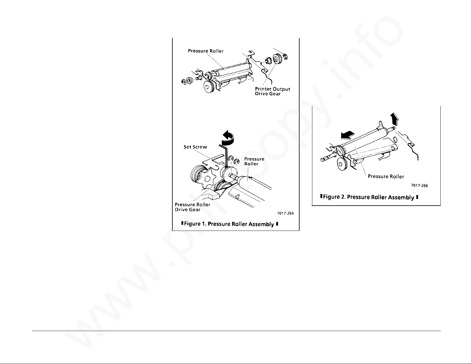
REP 4.11 Pressure Roller
www.printcopy.info
www.printcopy.info
Assembly
Parts List on PL 4.2
Removal
1. Remove power cord.
2. Remove document catch tray assembly
(REP 1.1).
3. Remove RH cover (REP 1.2).
4. Remove coupler cover (REP 1.3).
5. Remove LH cover (REP 1.4).
6. Remove recording paper.
7. Remove lower paper guide assembly (REP
4.5).
8. Remove printer motor cover (REP 4.6).
9. Remove pressure roller assembly. (Figure
1)
a. Remove all E-rings on the pressure
roller assembly.
b. Remove printer output drive gear.
Replacement
1. Replace individual components as
needed.
2. Reinstall pressure roller assembly.
3. Position pressure roller drive gear directly
over planet gear #3 (white) and secure
with setscrew.
4. Reinstall remaining components in
reverse order. (Figure 2)
Telecopier 7017 / 7017SF 4-31
c. Remove RH and LH pressure roller
bearings.
d. Loosen setscrew in pressure roller
drive gear.
e. Slide pressure roller assembly fully
left to position pressure roller drive
gear against LH frame.
f. Remove pressure roller assembly.
12/88
REP 4.11
Page 67
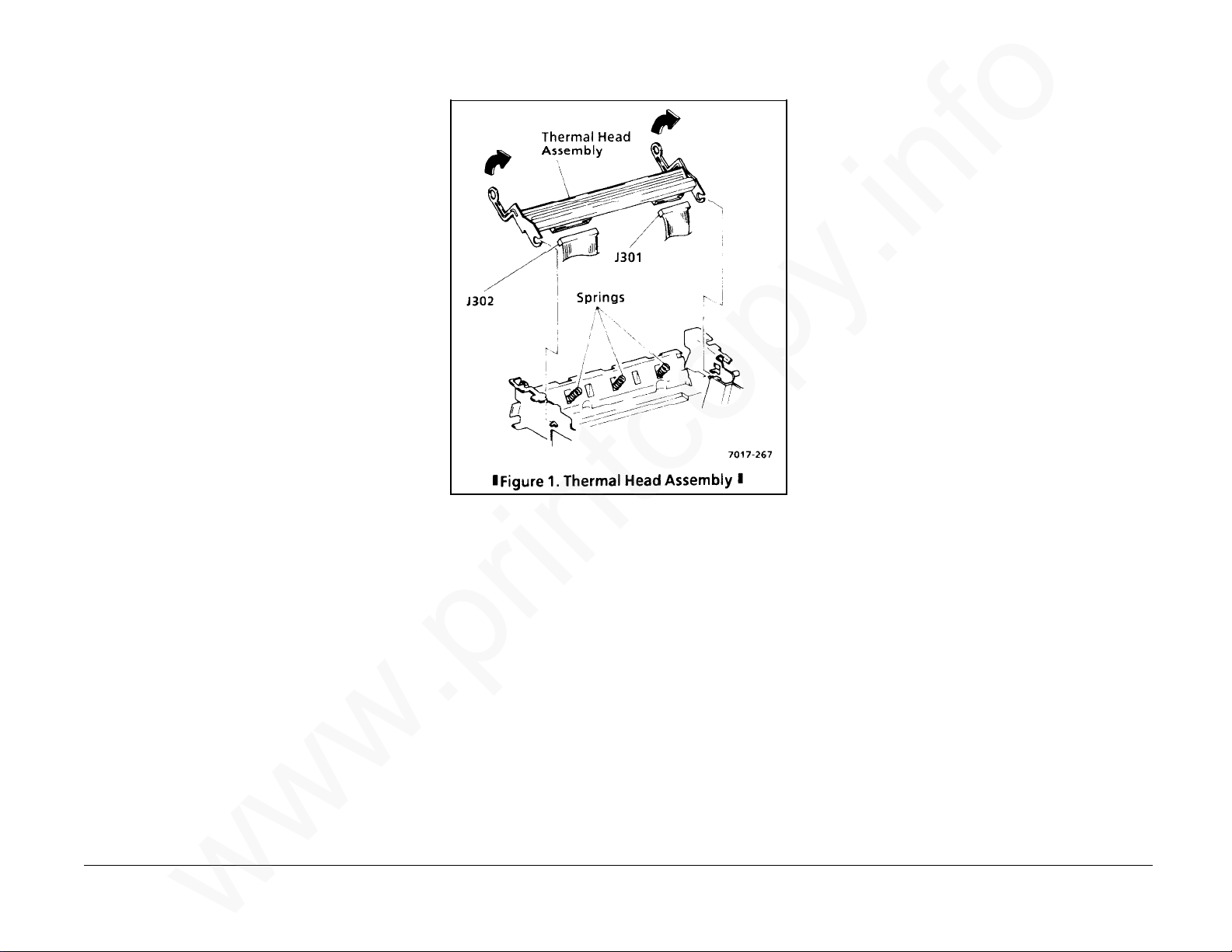
REP 4.12 Thermal Head Assembly
www.printcopy.info
www.printcopy.info
Parts List on PL 4.3
Removal
CAUTION
Follow electrostatic discharge precautions
(Section 6). Static electricity can damage this
component.
1. Remove power cord.
2. Remove document catch tray assembly
(REP 1.1).
3. Remove RH cover (REP 1.2).
4. Remove coupler cover (REP 1.3).
5. Remove LH cover (REP 1.4).
6. Remove recording paper.
7. Remove lower paper guide assembly (REP
4.5).
8. Remove printer motor cover (REP 4.6).
9. Remove upper printer assembly (REP 4.7).
10. Remove cutter (REP 4.9).
11. Remove printer output drive roller (REP
12. Remove pressure roller assembly (REP
13. Remove thermal head assembly. (Figure
REP 4.12 4-32 Telecopier 7017 / 7017SF
4.10).
4.11).
1)
a. Remove the two printer output drive
bearings.
b. Rotate thermal head assembly
forward and slide off studs on RH and
LH frames.
c. Disconnect J301 and J302 at thermal
head assembly.
Replacement
1. Ensure the three thermal head springs
are properly seated in the positioning
holes in the base frame and on the
locating points on the underside of the
thermal head assembly.
2. Reinstall in reverse order.
12/88
Page 68

REP 4.13 Cutter Crank Arm
www.printcopy.info
www.printcopy.info
Parts List on PL 4.2
Removal
1. Remove power cord.
2. Remove document catch tray assembly
(REP 1.1).
3. Remove coupler cover (REP 1.3).
4. Remove LH cover (REP 1.4).
Replacement
1. Reinstall the cutter crank arm.
a. Rotate the cutter thumbwheel until
the stud on the cutter crank pulley
aligns with the cutter crank arm.
b. Reinstall the cutter crank arm and
secure with the E-rings.
2. Reinstall remaining components in
reverse order.
REP 4.14 Cutter Cam
Parts List on PL 4.2
Removal
1. Remove power cord.
2. Remove document catch tray assembly
(REP 1.1).
3. Remove RH cover (REP 1.2).
4. Remove coupler cover (REP 1.3).
5. Remove the cutter crank arm. (Figure 1)
a. Remove the two E-rings securing the
cutter crank arm.
b. RX: Remove spring.
c. Remove the cutter crank arm.
5. Remove LH cover (REP 1.4).
6. Remove upper printer assembly (REP 4.7).
7. Remove cutter (REP 4.9).
8. Remove cutter crank arm (REP 4.13).
9. Remove cutter cam.
a. Depress cutter solenoid plunger.
b. Remove cutter cam.
Replacement
Reinstall in reverse order.
Telecopier 7017 / 7017SF 4-33
12/88
REP 4.13, 4.14
Page 69

REP 4.15 Printer Motor
www.printcopy.info
www.printcopy.info
Replacement
Parts List on PL 4.4
Removal
1. Remove power cord.
2. Remove document catch tray assembly
(REP 1.1).
3. Remove RH cover (REP 1.2).
4. Remove coupler cover (REP 1.3).
5. Remove LH cover (REP 1.4).
6. Remove LH paper side plate (REP 1.11).
7. Remove recording paper.
8. Remove lower paper guide assembly (REP
4.5).
9. Remove printer motor cover (REP 4.6).
10. If installed, remove A8 store & forward
PWB (REP 5.4).
11. Remove A2 main PWB (REP 5.5).
12. Remove power supply assembly (REP 5.6).
13. Remove CNC PWB assembly (REP 5.10).
NOTE: Replacement motors have both J104
and J115 marked on the connector. Printer
motor connector should be marked as J115.
1. If printer motor was replaced, delete J104
on the connector.
2. Reinstall in reverse order.
14. Remove printer motor. (Figure 1)
REP 4.15 4-34 Telecopier 7017 / 7017SF
a. Remove the three screws securing the
printer motor.
b. Loosen printer belt at printer motor.
c. Remove printer motor harness from
twist tie.
d. Remove printer motor.
12/88
Page 70
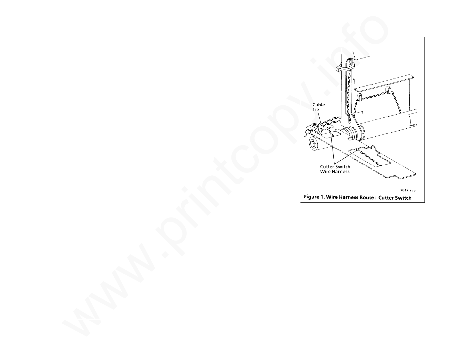
REP 4.16 Cutter Belt
www.printcopy.info
www.printcopy.info
REP 4.17 Cutter Switch
Parts List on PL 4.4
Removal
1. Remove power cord.
2. Remove document catch tray assembly
(REP 1.1).
3. Remove coupler cover (REP 1.3).
4. Remove LH cover (REP 1.4).
5. Remove cutter crank arm (REP 4.13).
6. Remove cutter belt.
Replacement
Reinstall in reverse order.
Parts List on PL 4.4
Removal
1. Remove power cord.
2. Remove document catch tray assembly
(REP 1.1).
3. Remove coupler cover (REP 1.3).
4. Remove LH cover (REP 1.4).
5. Remove cutter switch.
a. Disconnect J113 at A0 CNC PWB.
b. Cut cable tie securing cutter switch
harness.
c. Remove cutter switch harness from
cable clamp.
d. Manually rotate the cutter
thumbwheel until cutter switch
deactuates.
e. Remove screw securing cutter switch.
f. Remove cutter switch.
Replacement
Telecopier 7017 / 7017SF 4-35
1. Reposition cutter switch on locating
point.
2. Reinstall screw securing cutter switch.
CAUTION
Position wires away from cutter belt.
3. Secure cutter switch harness in cable
clamp.
4. Replace cable tie. (Figure 1)
5. Reinstall remaining components in
reverse order.
12/88
REP 4.16, 4.17
Page 71
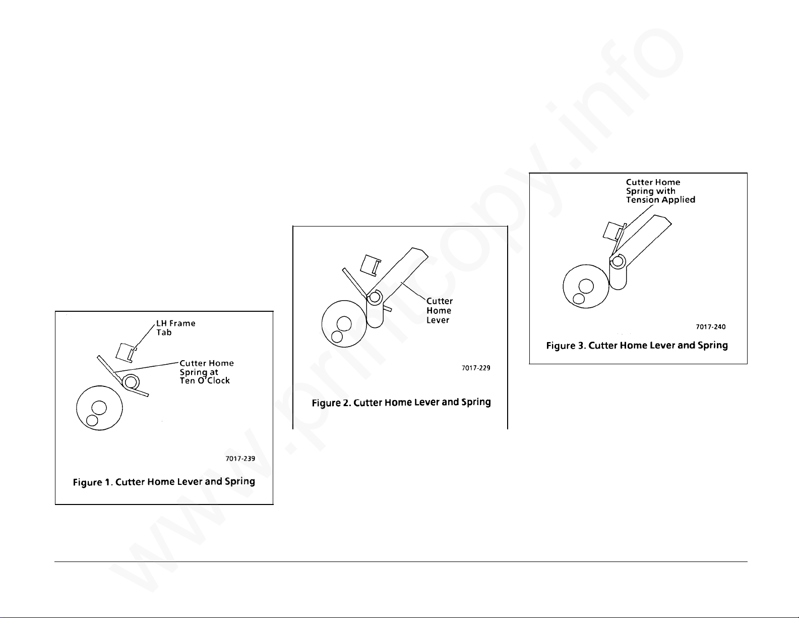
REP 4.18 Cutter Home Lever
www.printcopy.info
www.printcopy.info
and/or Cutter Home Spring
Parts List on PL 4.4
Removal
1. Remove power cord.
2. Remove document catch tray assembly
(REP 1.1).
3. Remove coupler cover (REP 1.3).
4. Remove LH cover (REP 1.4).
5. Remove the cutter crank arm (REP 4.13).
6. Remove the cutter belt.
7. Remove the cutter switch (REP 4.17).
8. Remove the cutter home lever and cutter
home spring.
a. Release the cutter home spring from
the LH frame tab. (Figure 1)
b. Remove the E-ring securing the cutter
home lever.
c. Remove the cutter home lever.
d. Remove the cutter home spring.
Replacement
1. Reinstall the cutter home lever and cutter
home spring.
a. Position the cutter home spring with
the long arm at ten o’clock. (Figure
1)
b. Reinstall the cutter home lever and
secure with the E-ring. (Figure 2)
c. Reposition the long arm of the cutter
home spring to the front of the
locating tab on the LH frame. (Figure
3)
2. Reinstall remaining components in
reverse order.
CAUTION
Position wires away from cutter belt.
3. If necessary, reposition wires.
REP 4.18 4-36 Telecopier 7017 / 7017SF
12/88
Page 72

REP 4.19 Planetary Assembly
www.printcopy.info
www.printcopy.info
Parts List on PL 4.4
Removal
1. Remove power cord.
2. Remove document catch tray assembly
(REP 1.1).
3. Remove RH cover (REP 1.2).
4. Remove coupler cover (REP 1.3).
5. Remove LH cover (REP 1.4).
6. Remove recording paper.
7. Remove lower paper guide assembly (REP
4.5).
8. Remove printer motor cover (REP 4.6).
9. Remove pressure roller assembly (REP
4.11).
10. Remove cutter crank arm (REP 4.13).
11. Remove cutter belt.
12. Remove planetary assembly.
a. Remove the two screws and spacer
securing planet bracket.
b. Remove planet bracket.
c. Loosen printer belt at printer motor.
d. Remove planet gears and planet
pulley.
Replacement
CAUTION
The three planet gear #2 are easily dislodged.
Ensure that the three planet gear #2 are
properly seated before reinstalling.
1. Apply a very small amount of 70P87 to
the internal teeth and internal
contacting surfaces of the planetary
assembly. (Figure 1)
NOTE: Ensure 70P87 is not on external
surfaces of the planetary assembly.
2. Ensure shoulders of the three planet gear
#2 are positioned towards the brass gear
(planet gear #1).
Telecopier 7017 / 7017SF 4-37
3. Reinstall in reverse order.
12/88
REP 4.19
Page 73

REP 4.20 Cutter Crank Pulley
www.printcopy.info
www.printcopy.info
REP 4.21 Cutter Clutch
Parts List on PL 4.4
Removal
1. Remove power cord.
2. Remove document catch tray assembly
(REP 1.1).
3. Remove RH cover (REP 1.2).
4. Remove coupler cover (REP 1.3).
5. Remove LH cover (REP 1.4).
6. Remove recording paper.
7. Remove lower paper guide assembly (REP
4.5).
8. Remove printer motor cover (REP 4.6).
9. Remove upper printer assembly (REP 4.7).
10. Remove cutter (REP 4.9).
11. Remove printer output drive roller (REP
4.10).
12. Remove pressure roller assembly (REP
4.11).
13. Remove thermal head assembly (REP
4.12).
14. Remove cutter crank arm (REP 4.13).
15. Remove cutter belt.
16. Remove cutter crank pulley. (Figure 1)
a. Remove E-ring securing the cutter
crank pulley.
Replacement
1. Reinstall cutter crank pulley.
a. Position one of the cutter crank
bearings on the cutter crank pulley.
b. Reposition cutter home lever and
hold until cutter crank pulley is
repositioned.
c. Reinstall both bearings and cutter
crank pulley with detent positioned
at cutter home lever.
d. Reinstall E-ring to secure cutter crank
pulley.
2. Reinstall remaining components in
reverse order.
Parts List on PL 4.4
Removal
1. Remove power cord.
2. Remove document catch tray assembly
(REP 1.1).
3. Remove RH cover (REP 1.2).
4. Remove coupler cover (REP 1.3).
5. Remove LH cover (REP 1.4).
6. Remove recording paper.
7. Remove lower paper guide assembly (REP
4.5).
8. Remove printer motor cover (REP 4.6).
9. Remove upper printer assembly (REP 4.7).
10. Remove cutter (REP 4.9).
Continued
REP 4.20, 4.21 4-38 Telecopier 7017 / 7017SF
b. Remove the cutter crank pulley.
c. Remove both cutter crank bearings.
12/88
Page 74

REP 4.21 Cutter Clutch
www.printcopy.info
www.printcopy.info
(continued)
REP 4.22 Cutter Solenoid
Assembly
Replacement
1. Reposition cutter solenoid bracket.
11. Remove printer output drive roller (REP
4.10).
12. Remove pressure roller assembly (REP
4.11).
13. Remove thermal head assembly (REP
4.12).
14. Remove cutter crank arm (REP 4.13).
15. Remove cutter belt.
16. Remove planetary assembly (REP 4.19).
17. Remove cutter crank pulley (REP 4.20).
18. Remove cutter clutch.
a. Manually actuate cutter solenoid.
b. Remove the cutter clutch.
Replacement
Reinstall in reverse order.
Parts List on PL 4.4
Removal
1. Remove power cord.
2. Remove document catch tray assembly
(REP 1.1).
3. Remove coupler cover (REP 1.3).
4. Remove LH cover (REP 1.4).
5. Remove output tray assembly (REP 1.5).
6. Remove rear cover (REP 1.6).
7. Remove cutter solenoid assembly.
a. Remove cutter solenoid assembly
harness from cable clamp.
b. Remove J118 at A0 CNC PWB.
c. Remove the two screws securing
cutter solenoid assembly to the LH
frame.
d. Remove cutter solenoid assembly.
2. Reposition cutter solenoid plunger pin to
engage in cutter solenoid lever. (Figure
1)
Telecopier 7017 / 7017SF 4-39
3. Secure cutter solenoid assembly to the LH
frame with the two screws.
4. Reinstall in reverse order.
12/88
REP 4.21, 4.22
Page 75
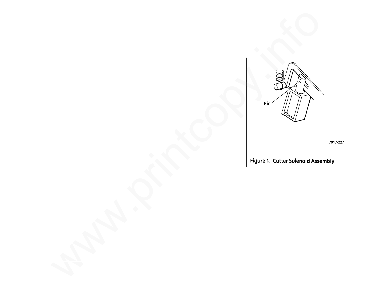
REP 4.21 Cutter Clutch
www.printcopy.info
www.printcopy.info
(continued)
REP 4.22 Cutter Solenoid
Assembly
Replacement
1. Reposition cutter solenoid bracket.
11. Remove printer output drive roller (REP
4.10).
12. Remove pressure roller assembly (REP
4.11).
13. Remove thermal head assembly (REP
4.12).
14. Remove cutter crank arm (REP 4.13).
15. Remove cutter belt.
16. Remove planetary assembly (REP 4.19).
17. Remove cutter crank pulley (REP 4.20).
18. Remove cutter clutch.
a. Manually actuate cutter solenoid.
b. Remove the cutter clutch.
Replacement
Reinstall in reverse order.
Parts List on PL 4.4
Removal
1. Remove power cord.
2. Remove document catch tray assembly
(REP 1.1).
3. Remove coupler cover (REP 1.3).
4. Remove LH cover (REP 1.4).
5. Remove output tray assembly (REP 1.5).
6. Remove rear cover (REP 1.6).
7. Remove cutter solenoid assembly.
a. Remove cutter solenoid assembly
harness from cable clamp.
b. Remove J118 at A0 CNC PWB.
c. Remove the two screws securing
cutter solenoid assembly to the LH
frame.
d. Remove cutter solenoid assembly.
2. Reposition cutter solenoid plunger pin to
engage in cutter solenoid lever. (Figure
1)
Telecopier 7017 / 7017SF 4-39
3. Secure cutter solenoid assembly to the LH
frame with the two screws.
4. Reinstall in reverse order.
12/88
REP 4.21, 4.22
Page 76

REP 4.23 Cutter Solenoid Lever
www.printcopy.info
www.printcopy.info
Parts List on PL 4.4
Removal
1. Remove power cord.
2. Remove document catch tray assembly
(REP 1.1).
3. Remove RH cover (REP 1.2).
4. Remove coupler cover (REP 1.3).
5. Remove LH cover (REP 1.4).
6. Remove output tray assembly (REP 1.5).
7. Remove rear cover (REP 1.6).
8. Remove recording paper.
9. Remove lower paper guide assembly (REP
4.5).
10. Remove printer motor cover (REP 4.6).
11. Remove pressure roller assembly (REP
4.11).
12. Remove cutter solenoid assembly (REP
4.22).
Replacement
Reinstall in reverse order.
13. Remove cutter solenoid spring.
14. Remove cutter solenoid lever. (Figure 1)
NOTE: If thermal head assembly is removed,
skip steps a through d.
REP 4.23 4-40 Telecopier 7017 / 7017SF
a. Remove E-ring securing LH printer
pivot bearing.
b. Remove screw securing LH frame to
power supply housing.
c. Remove screw (located beneath
cutter solenoid lever stud) securing
LH frame to base frame.
d. d. Gently separate LH frame from base
frame to obtain clearance for the
removal of the cutter solenoid lever.
e. Remove cutter solenoid lever from
the stud on the LH frame.
12/88
Page 77

REP 4.24 Printer Belt
www.printcopy.info
www.printcopy.info
Parts List on PL 4.4
Removal
1. Remove power cord.
2. Remove document catch tray assembly
(REP 1.1).
3. Remove RH cover (REP 1.2).
4. Remove coupler cover (REP 1.3).
5. Remove LH cover (REP 1.4).
6. Remove output tray assembly (REP 1.5).
7. Remove rear cover (REP 1.6).
8. Remove recording paper.
9. Remove lower paper guide assembly (REP
4.5).
10. Remove printer motor cover (REP 4.6).
11. Remove upper printer assembly (REP 4.7).
12. Remove cutter (REP 4.9).
13. Remove printer output drive roller (REP
4.10).
14. Remove pressure roller assembly (REP
4.11).
15. Remove thermal head assembly (REP
4.12).
16. Remove cutter crank arm (REP 4.13).
17. Remove cutter belt.
18. Remove planetary assembly (REP 4.19).
19. Remove cutter crank pulley (REP 4.20).
20. Remove cutter clutch (REP 4.21).
21. Remove cutter solenoid assembly (REP
4.22).
22. Remove cutter solenoid spring.
23. Remove cutter solenoid lever (REP 4.23).
24. Remove printer belt.
a. Slide printer belt through gap
between base frame and thermal
head stud.
b. Separate rear of LH frame from
printer drive bracket.
(1.) Remove screw (located beneath
cutter solenoid lever stud)
securing LH frame to printer drive
bracket. (Figure 1)
(2.) Gently separate LH frame from
printer drive bracket to obtain
clearance for the removal of the
printer belt.
c. Remove printer belt.
Telecopier 7017 / 7017SF 4-41
Replacement
Reinstall in reverse order.
12/88
REP 4.24
Page 78

REP 5.1 A6 Control Panel and/or
www.printcopy.info
www.printcopy.info
Control Panel Assembly
Replacement
1. Replace overlays as needed.
Parts List on PL 5.2
Removal
CAUTION
Follow electrostatic discharge precautions
(Section 6). Static electricity can damage this
component.
1. Remove power cord.
2. Remove document catch tray assembly
(REP 1.1).
3. Remove coupler cover (REP 1.3).
4. Remove LH cover (REP 1.4).
5. Remove scan support assembly.
6. Remove control panel assembly.
a. Disconnect J111 at A0 CNC PWB.
(Figure 1)
b. Remove screw securing ground wire
to LH frame.
c. Remove control panel assembly
harness from cable clamp.
d. Remove remaining screw securing
control panel assembly to upper scan
cover.
2. Reinstall in reverse order.
e. Raise control panel assembly above
REP 5.1 4-42 Telecopier 7017 / 7017SF
upper scan cover. (Figure 2)
f. Thread control panel assembly
harness through the cutout in upper
scan cover.
12/88
Page 79

REP 5.2 Speaker Assembly
www.printcopy.info
www.printcopy.info
REP 5.3 Fan
Parts List on PL 5.2
Removal
1. Remove power cord.
2. Remove document catch tray assembly
(REP 1.1).
3. Remove coupler cover (REP 1.3).
4. Remove LH cover (REP 1.4).
5. Remove speaker assembly. (Figure 1)
a. Disconnect J101 from A0 CNC PWB.
b. Remove screw securing speaker
bracket to LH frame.
c. Lift speaker assembly up to clear base
plate, then forward to remove.
Parts List on PL 5.1
Removal
1. Remove power cord.
2. Remove document catch tray assembly
(REP 1.1).
3. Remove coupler cover (REP 1.3).
4. Remove LH cover (REP 1.4).
5. Remove output tray assembly (REP 1.5).
6. Remove rear cover (REP 1.6).
7. Remove fan. (Figure 1)
a. Remove fan harness from cable
clamp.
b. Disconnect J119 from A0 CNC PWB.
c. Remove the two screws securing fan
to power supply housing.
d. Remove fan from cutout in power
supply housing.
Replacement
Reinstall in reverse order.
Replacement
Reinstall in reverse order.
Telecopier 7017 / 7017SF 4-43
12/88
REP 5.2, 5.3
Page 80
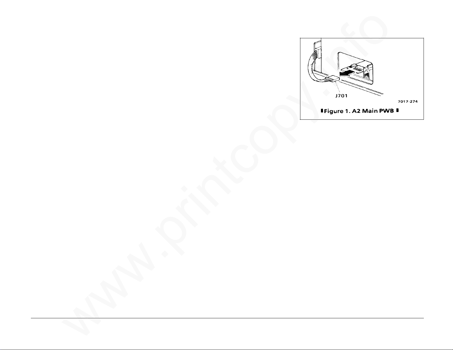
REP 5.4 A8 Store & Forward PWB
www.printcopy.info
www.printcopy.info
REP 5.5 A2 Main PWB
Parts List on PL 5.3
Removal
CAUTION
Follow electrostatic discharge precautions
(Section 6). Static electricity can damage this
component.
1. Remove power cord.
2. Remove document catch tray assembly
(REP 1.1).
3. Remove RH cover (REP 1.2).
4. Remove A8 store & forward PWB.
a. Loosen the two screws securing A8
store & forward PWB to power supply
assembly.
b. Loosen the one screw securing A8
store & forward PWB to the RH
frame.
c. Remove A8 store & forward PWB.
Replacement
1. Align connectors on the two PWB.
2. USO: Ensure ground plate contacts the
top side of the base plate.
3. Reinstall in reverse order.
Parts List on PL 5.3
Removal
CAUTION
Follow electrostatic discharge precautions
(Section 6). Static electricity can damage this
component.
1. Remove power cord.
2. Remove document catch tray assembly
(REP 1.1).
3. Remove coupler cover (REP 1.3).
4. Remove RH cover (REP 1.2).
5. If installed, remove A8 store & forward
PWB (REP 5.4).
6. Remove A2 main PWB.
a. Disconnect J701 at A10 coupler PWB.
(Figure 1)
b. If necessary, loosen screw securing
the PWB retainer (near right rear of
A2 main PWB), slide the PWB retainer
toward rear of machine, and
retighten screw.
NOTE: Only machines with serial
number (TBD) and above have the
PWB retainer.
c. Remove A2 main PWB.
Continued
REP 5.4, 5.5 4-44 Telecopier 7017 / 7017SF
7. If replacing A2 main PWB, perform the
following:
a. Remove A5 modem PWB (REP 5.8).
b. Remove A10 coupler PWB (REP 5.9).
12/88
Page 81
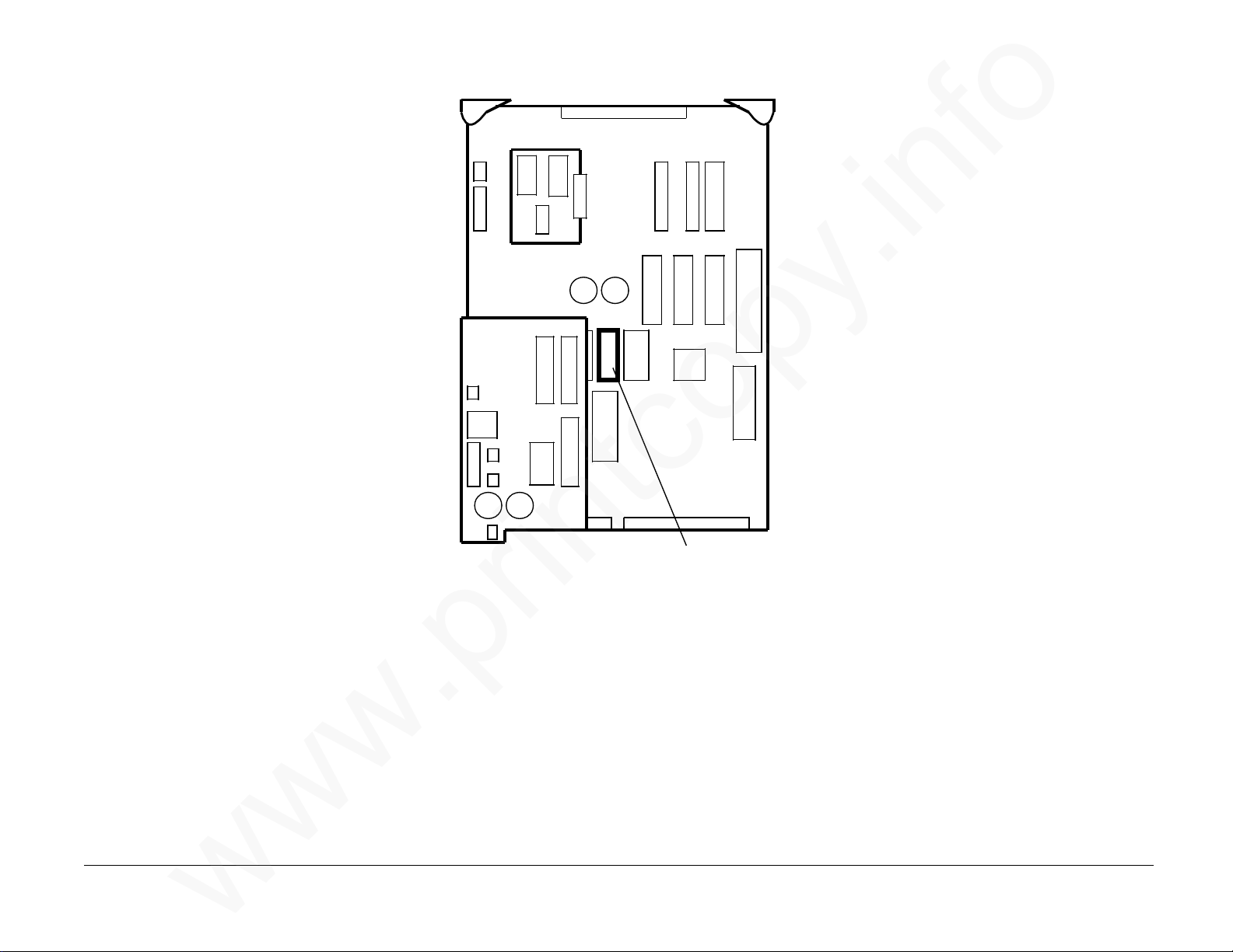
REP 5.5 A2 Main PWB
www.printcopy.info
www.printcopy.info
(continued)
Replacement
NOTE: The E2PROM on the A2 Main PWB
contains all system data. If it is moved onto a
replacement PWB, the system data including
the Operator selections and the copy count is
retained. However, if a previous problem
persists, the old E
new E
programmed with the Operator selections and
system data.
1. If replacing A2 Main PWB, switch
During reinstallation of A2 main PWB, ensure
the main standoffs clear the base plate.
2. Reinstall remaining components in
2
PROM must be installed and
E2PROM (U49) on the old and new PWB.
(Figure 2)
reverse order.
NOTE: PWB retainer, if installed, need
not be positioned to retain A2 Main PWB
unless machine is to be shipped.
2
PROM is a suspect and the
CAUTION
REP 5.6 Power Supply Assembly
Parts List on PL 5.1
Removal
1. Remove power cord.
2. Remove document catch tray assembly
(REP 1.1).
3. Remove RH cover (REP 1.2).
4. If installed, remove A8 store & forward
PWB (REP 5.4).
5. Remove power supply assembly.
a. Remove the two screws securing the
power supply assembly to the power
supply housing.
b. Remove power supply assembly.
Replacement
Reinstall in reverse order.
3. If the PWB was replaced, check the
Telecopier 7017 / 7017SF 4-45
following and adjust as needed:
• Cutter Registration (ADJ 5.1)
• Scan Registration (ADJ 5.2).
U49
Figure 2. Location of E2 PROM U49
12/88
REP 5.5, 5.6
Page 82

REP 5.7 A3 Telephone Line Filter
www.printcopy.info
www.printcopy.info
PWB
Parts List on PL 5.4
Removal
1. Remove power cord.
2. Remove document catch tray assembly
(REP 1.1).
3. Remove coupler cover (REP 1.3).
4. Remove LH cover (REP 1.4).
5. USO: Remove A3 telephone line filter
PWB.
a. Remove J901 at A3 telephone line
filter PWB.
b. Remove screw securing the A3
telephone line filter PWB bracket to
base plate.
Replacement
Reinstall in reverse order.
REP 5.8 A5 Modem PWB
Parts List on PL 5.3
Removal
CAUTION
Follow electrostatic discharge precautions
(Section 6). Static electricity can damage this
component.
1. Remove power cord.
2. Remove document catch tray assembly
(REP 1.1).
3. Remove coupler cover (REP 1.3).
4. Remove RH cover (REP 1.2).
5. If installed, remove A8 store & forward
PWB (REP 5.4).
6. Remove A2 main PWB (REP 5.5).
7. Remove A5 modem PWB. (Figure 1)
a. Remove A5 modem PWB from the
two modem standoffs.
b. Remove A5 modem PWB from J4.
Replacement
Reinstall in reverse order.
REP 5.7, 5.8 4-46 Telecopier 7017 / 7017SF
12/88
Page 83
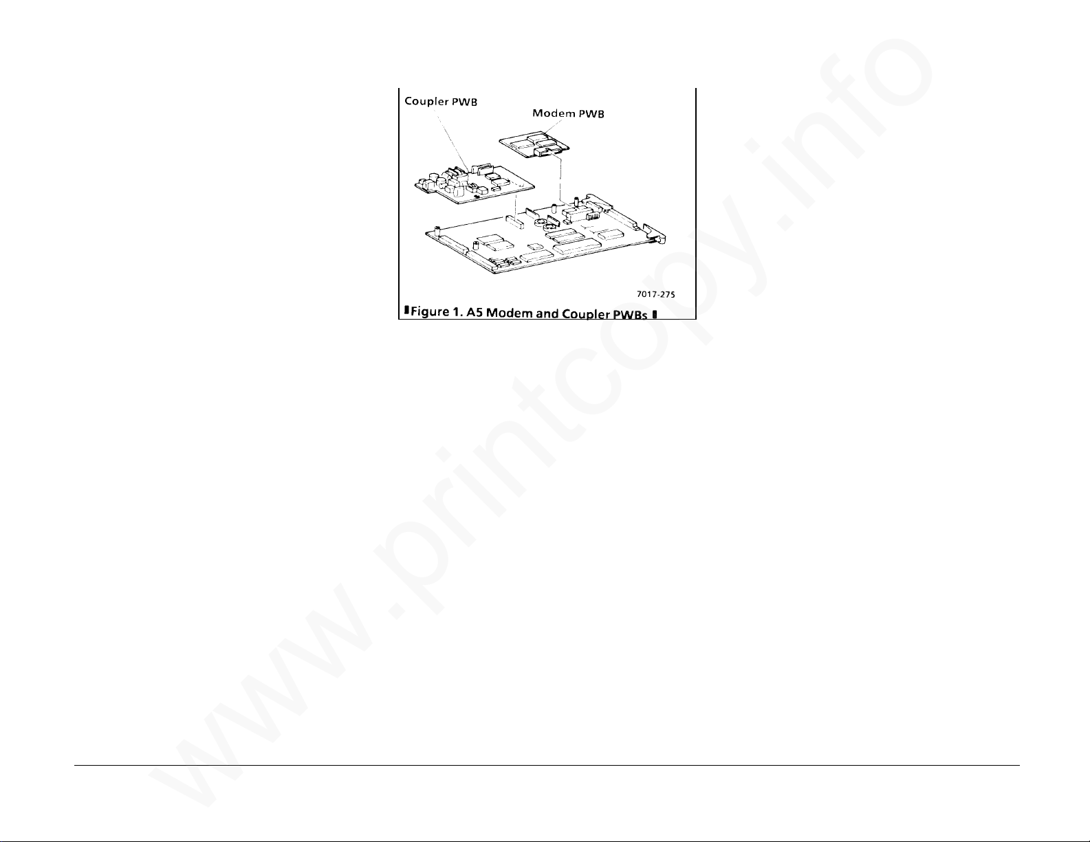
REP 5.9 A10 Coupler PWB
www.printcopy.info
www.printcopy.info
REP 5.10 CNC PWB Assembly
Parts List on PL 5.3
Removal
CAUTION
Follow electrostatic discharge precautions
(Section 6). Static electricity can damage this
component.
1. Remove power cord.
2. Remove document catch tray assembly
(REP 1.1).
3. Remove coupler cover (REP 1.3).
4. Remove RH cover (REP 1.2).
5. If installed, remove A8 store & forward
PWB (REP 5.4).
6. Remove A2 main PWB (REP 5.5).
7. Remove A10 coupler PWB. (Figure 1)
a. Remove A10 coupler PWB from the
two coupler standoffs and J3.
b. Record the position of all bits on any
switches on A10 PWB.
c. Record the position of all links on A10
PWB.
Figure 1. A5 Modem and Coupler PWBs
Replacement
1. Position all bits as recorded in Removal.
2. Position all links as recorded in Removal.
3. Reinstall in reverse order.
Parts List on PL 5.4
Removal
1. Remove power cord.
2. Remove document catch tray assembly
(REP 1.1).
3. Remove RH cover (REP 1.2).
4. Remove coupler cover (REP 1.3).
5. Remove LH cover (REP 1.4).
6. If installed, remove A8 store & forward
PWB (REP 5.4).
7. Remove A2 main PWB (REP 5.5).
8. Remove power supply assembly (REP 5.6).
9. Remove CNC PWB assembly.
a. Cut the two cable ties securing wire
harnesses to A0 CNC PWB.
b. Remove cable clamp from CNC
bracket.
c. Disconnect all jacks, except J120,
from A0 CNC PWB.
d. Remove the three screws securing
EME bracket and EME shield to base
plate.
Telecopier 7017 / 7017SF 4-47
e. Remove EME bracket.
f. Remove screw securing CNC bracket
to power supply housing.
g. Remove CNC PWB assembly.
h. Disconnect J120.
Continued
12/88
REP 5.9, 5.10
Page 84

REP 5.10 CNC PWB Assembly
www.printcopy.info
www.printcopy.info
(continued)
Replacement
1. Connect J120.
2. Reinstall CNC PWB assembly.
3. Ensure A0 CNC PWB is positioned in the
locating tabs on the base plate.
4. Position CNC bracket to align locating
hole and point, then secure with screw.
5. Reinstall and/or replace remaining
components in reverse order.
ADJ 5.1 Cutter Registration
Purpose
The purpose is to time the cutter actuation so
that paper is cut at the trail edge of the image.
Check
1. Clean the pressure roller.
a. Open printer and remove recording
paper.
b. Clean the exposed area of the
pressure roller using Xerox CLEANUPS. Rotate the roller to clean the
complete roller surface.
c. Reload recording paper and close
printer.
2. Enter Service Mode.
3. Print four test patterns.
a. Select Menu 61.
b. Press the Start button.
c. The test pattern will continue to print
until the Stop button is pressed. Press
the Stop button after the fourth test
pattern is cut.
d. Retain the second, third, and fourth
test patterns for step 4.
4. Verify the cutter registration.
a. Examine the second, third, and
fourth test patterns for five
horizontal lines at both the lead edge
and the trail edge.
b. Examine the second, third, and
fourth test patterns for a maximum
of 2 mm of white on the trail edge.
c. If the printed test patterns vary by
more than 1 mm, correct the varying
registration problem (RAP 2.3.6),
then recheck cutter registration.
NOTE: For the next two checks, pick the test
pattern that best represents the average
position of the three test patterns.
d. If five lines are printed at lead edge
and trail edge of copy and less than 2
mm of white is on the trail edge
(Figure 2), the cutter registration is
correct.
e. If six or more lines are printed on the
lead edge and four or less lines are
printed on trail edge (Figure 1) or
more than 2 mm of white is on the
trail edge (Figure 3), perform the
cutter registration adjustment.
Adjustment
1. Perform the Check to verify that cutter
registration needs adjustment.
2. Verify that the Service mode is selected.
3. Determine current Systems Data Setup
for cutter registration.
a. Select Menu 22 to print Options
Report.
b. Press the Start button.
c. Highlight Systems Data Setup No. 10
and the corresponding DATA.
4. Determine adjustment needed.
a. Compare the test patterns from the
cutter registration check to the test
patterns in Figures 1 through 3.
REP 5.10, ADJ 5.1 4-48 Telecopier 7017 / 7017SF
Continued
12/88
Page 85

REP 5.10 CNC PWB Assembly
www.printcopy.info
www.printcopy.info
(continued)
Replacement
1. Connect J120.
2. Reinstall CNC PWB assembly.
3. Ensure A0 CNC PWB is positioned in the
locating tabs on the base plate.
4. Position CNC bracket to align locating
hole and point, then secure with screw.
5. Reinstall and/or replace remaining
components in reverse order.
ADJ 5.1 Cutter Registration
Purpose
The purpose is to time the cutter actuation so
that paper is cut at the trail edge of the image.
Check
1. Clean the pressure roller.
a. Open printer and remove recording
paper.
b. Clean the exposed area of the
pressure roller using Xerox CLEANUPS. Rotate the roller to clean the
complete roller surface.
c. Reload recording paper and close
printer.
2. Enter Service Mode.
3. Print four test patterns.
a. Select Menu 61.
b. Press the Start button.
c. The test pattern will continue to print
until the Stop button is pressed. Press
the Stop button after the fourth test
pattern is cut.
d. Retain the second, third, and fourth
test patterns for step 4.
4. Verify the cutter registration.
a. Examine the second, third, and
fourth test patterns for five
horizontal lines at both the lead edge
and the trail edge.
b. Examine the second, third, and
fourth test patterns for a maximum
of 2 mm of white on the trail edge.
c. If the printed test patterns vary by
more than 1 mm, correct the varying
registration problem (RAP 2.3.6),
then recheck cutter registration.
NOTE: For the next two checks, pick the test
pattern that best represents the average
position of the three test patterns.
d. If five lines are printed at lead edge
and trail edge of copy and less than 2
mm of white is on the trail edge
(Figure 2), the cutter registration is
correct.
e. If six or more lines are printed on the
lead edge and four or less lines are
printed on trail edge (Figure 1) or
more than 2 mm of white is on the
trail edge (Figure 3), perform the
cutter registration adjustment.
Adjustment
1. Perform the Check to verify that cutter
registration needs adjustment.
2. Verify that the Service mode is selected.
3. Determine current Systems Data Setup
for cutter registration.
a. Select Menu 22 to print Options
Report.
b. Press the Start button.
c. Highlight Systems Data Setup No. 10
and the corresponding DATA.
4. Determine adjustment needed.
a. Compare the test patterns from the
cutter registration check to the test
patterns in Figures 1 through 3.
REP 5.10, ADJ 5.1 4-48 Telecopier 7017 / 7017SF
Continued
12/88
Page 86
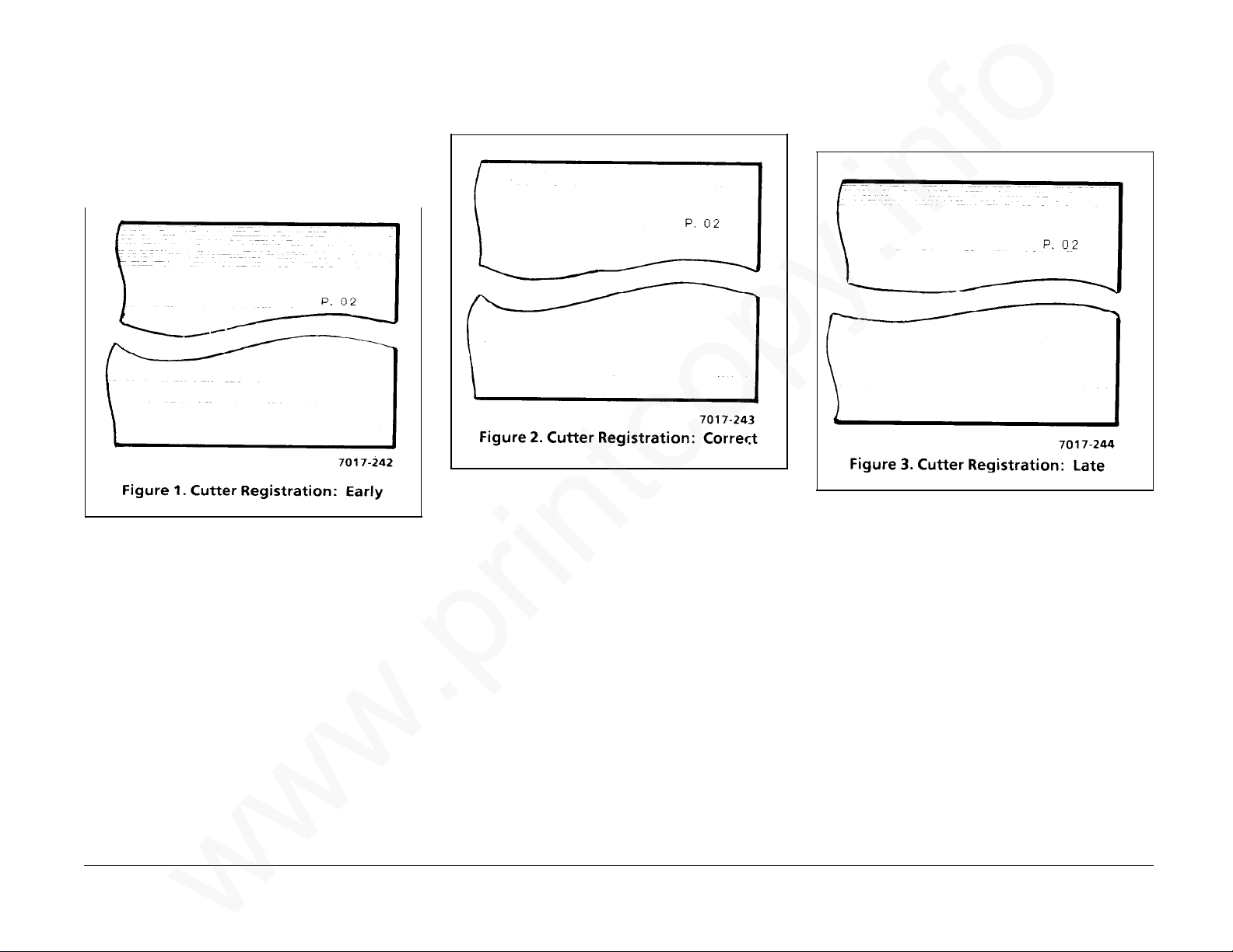
ADJ 5.1 Cutter Registration
www.printcopy.info
www.printcopy.info
(continued)
The following test pattern illustrates the
cutter registration adjustment too early
(negative) resulting in too many lines on lead
edge and too few lines on trail edge.
The following test pattern illustrates the
cutter registration adjustment when it is
correct.
The following test pattern illustrates the
cutter registration adjustment too late
(positive) resulting in too much white space on
trail edge.
Telecopier 7017 / 7017SF 4-49
Continued
12/88
ADJ 5.1
Page 87

ADJ 5.1 Cutter Registration
www.printcopy.info
www.printcopy.info
(continued)
b. If more than 5 lines were printed on
the top of the test patterns, select a
bit setting from Table 1 that is two
positions more towards positive than
your current setting for each extra
line that was printed.
c. If more than 2 mm of white is printed
at the bottom of the test pattern,
select a bit setting from Table 1 that
is one position more towards
negative than your current setting
for each extra 0.5 mm of white.
Table 1
System Data: 10
5. Adjust System Data Setup No. 10.
a. Select Menu 81. The display
indicates:
81 SYSTEM DATA SETUP
PRESS [START] OR [SCROLL]
b. Press the Start button. The display
indicates:
81 CAUTION: CHANGE WILL EFFECT OPERATION
PRESS [START] OR [STOP]
c. Press the Start button. The display
indicates:
81 SYSTEM DATA NUMBER>01DATA 00000000
ENTER 2 DIGIT SYSTEM DATA NUMBER
NOTE: The display returns to Idle after 30
seconds. It is advisable to have the needed
information ready to input.
CAUTION
Do not arbitrarily change System Data
Parameters. To do so may violate CCITT
Standards and cause improper Terminal
operations.
d. Enter the System Data Setup No: 10.
e. Press Enter.
Continued
ADJ 5.1 4-50 Telecopier 7017 / 7017SF
Description
Scan registration
(mm)
Cutter registration
(mm)
Bit No.
0
1
2
3
4
5
6
7
Bit Definition
0 1
3210 3210 3210
0000: -4.0 0110: -1.0 1100: +2.0
0001: -3.5 0111: -0.5 1101: +2.5
0010: -3.0 1000: ±0 1110: +3.0
0011: -2.5 1001: +0.5 1111: +3.5
0100: -2.0 1010: +1.0
0101:-.5 1011: +1.5
7654 7654 7654
0000: -4.0 0110: -1.0 1100: +2.0
0001: -3.5 0111: -0.5 1101: +2.5
0010: -3.0 1000: ±0 1110: +3.0
0011: -2.5 1001: +0.5 1111: +3.5
0100: -2.0 1010: +1.0
0101:-1.5 1011: +1.5
12/88
Default
USO RX
0 0
0 0
0 0
1 1
0 0
0 0
0 0
1 1
Page 88

ADJ 5.1 Cutter Registration
www.printcopy.info
www.printcopy.info
(continued)
NOTE: The Display example below is an
enlargement of the Data bit numbers as seen
in the display. Above it are the corresponding
bit numbers found in Table 1.
BITS 76543210
DATA 10001000
f. Press the Select button to move the
cursor beneath the bit number (7, 6,
5, or 4) you wish to change.
g. Press the number “1“ or “0“ on the
keypad.
h. Move the cursor to the next bit
number or press Enter to effect the
change.
j. Press Stop. The terminal will reboot
and retain the changes.
6. Verify that new setting achieves the
correct position by performing the Check
again. Reposition as needed.
7. Check the scan registration. (ADJ 6.2)
Telecopier 7017 / 7017SF 4-51
12/88
ADJ 5.1
Page 89

ADJ 5.2 Scan Registration
www.printcopy.info
www.printcopy.info
Purpose
The purpose is to time the scanner so that both
the lead edge and the trail edge is printed.
Check
NOTE: The cutter registration Check /
Adjustment (ADJ 5.1) must be correct prior to
checking the Scan registration.
1. Clean the following using Xerox CLEANUPS:
a. ADF belt
b. retard roller
c. lower scanner drive rollers
d. platen roller
e. upper scanner idler rollers
2. Make three single copies of test pattern
82P151.
3. Verify the scan registration.
a. Examine copies for tips of the
registration arrows on both the lead
edge and the trail edge.
c. If the copies vary by more than 1 mm,
correct the varying registration
problem (RAP 2.3.6), then recheck
scan registration.
d. If registration arrows on the lead
edge are equal to the registration
arrows on the trail edge (Figure 2),
the scan registration is correct.
e. If registration arrows on the lead
edge are not equal to the ones on the
trail edge (Figures 1 and 3), perform
the scan registration adjustment.
Adjustment
1. Perform the Check to verify that scan
registration needs adjustment.
2. Enter Service Mode.
3. Determine current Systems Data Setup
for cutter registration.
a. Select Menu 22 to print Options
Report.
b. Press the Start button.
c. Highlight Systems Data Setup No. 10
and the corresponding DATA.
4. Determine adjustment needed.
a. Compare the test patterns from the
scan registration check to the test
patterns in Figures 1 through 3.
Continued
ADJ 5.2 4-52 Telecopier 7017 / 7017SF
12/88
Page 90

ADJ 5.2 Scan Registration
www.printcopy.info
www.printcopy.info
(continued)
The following test pattern illustrates the scan
registration adjustment too early (negative)
resulting in the trail edge registration arrow
being cut off.
The following test pattern illustrates the scan
registration adjustment when it is correct.
The following test pattern illustrates the scan
registration adjustment too late (positive)
resulting in the lead edge registration arrow
being cut off.
Telecopier 7017 / 7017SF 4-53
Continued
12/88
ADJ 5.2
Page 91
ADJ 5.2 Scan Registration
www.printcopy.info
www.printcopy.info
(continued)
b. If the trail edge registration arrow
was cut off, select a bit setting from
Table 1 that is one position more
towards positive than your current
setting for each 0.5 mm that was cut
off.
c. If the lead edge registration arrow
was cut off, select a bit setting from
Table 1 that is one position more
towards negative than your current
setting for each 0.5 mm that was cut
off.
Table 1
System Data: 10
5. Adjust System Data Setup No. 10.
a. Select Menu 81. The display
indicates:
81 SYSTEM DATA SETUP
PRESS [START] OR [SCROLL]
b. Press the Start button. The display
indicates:
81 CAUTION: CHANGE WILL EFFECT OPERATION
PRESS [START] OR [STOP]
c. Press the Start button. The display
indicates:
81 SYSTEM DATA NUMBER>01DATA 00000000
ENTER 2 DIGIT SYSTEM DATA NUMBER
NOTE: The display returns to Idle after 30
seconds. It is advisable to have the needed
information ready to input.
CAUTION
Do not arbitrarily change System Data
Parameters. To do so may violate CCITT
Standards and cause improper Terminal
operations.
d. Enter the System Data Setup No: 10.
e. Press Enter.
Continued
ADJ 5.2 4-54 Telecopier 7017 / 7017SF
Description
Scan registration
(mm)
Cutter registration
(mm)
Bit No.
0
1
2
3
4
5
6
7
Bit Definition
0 1
3210 3210 3210
0000: -4.0 0110: -1.0 1100: +2.0
0001: -3.5 0111: -0.5 1101: +2.5
0010: -3.0 1000: ±0 1110: +3.0
0011: -2.5 1001: +0.5 1111: +3.5
0100: -2.0 1010: +1.0
0101:-.5 1011: +1.5
7654 7654 7654
0000: -4.0 0110: -1.0 1100: +2.0
0001: -3.5 0111: -0.5 1101: +2.5
0010: -3.0 1000: ±0 1110: +3.0
0011: -2.5 1001: +0.5 1111: +3.5
0100: -2.0 1010: +1.0
0101:-1.5 1011: +1.5
12/88
Default
USO RX
0 0
0 0
0 0
1 1
0 0
0 0
0 0
1 1
Page 92

ADJ 5.2 Scan Registration
www.printcopy.info
www.printcopy.info
(continued)
NOTE: The Display example below is an
enlargement of the Data bit numbers as seen
in the display. Above it are the corresponding
bit numbers found in Table 1.
BITS 76543210
DATA 1 0 0 0 1000
f. Press the Select button to move the
cursor beneath the bit number (3, 2,
1, or 0) you wish to change.
g. Press the number “1“ or “0“ on the
keypad.
h. Move the cursor to the next bit
number or press Enter to effect the
change.
j. Press Stop. The terminal will reboot
and retain the changes.
6. Verify that new setting achieves the
correct position by performing the Check
again. Reposition as needed.
Telecopier 7017 / 7017SF 4-55
12/88
ADJ 5.2
Page 93

5. Parts List
Parts List Introduction 5-2●
Covers and Panels
PL 1.1 Trays 5-3●
PL 1.2 Covers 5-4●
PL 1.3 Frames 5-5●
ADF
PL 2.1 Upper ADF 5-6●
PL 2.2 Lower ADF 5-7●
Scanner
PL 3.1 Upper Scan Electronics 5-8●
PL 3.2 Upper Scan Drives 5-9●
PL 3.3 Lower Scan 5-10●
Printer
PL 4.1 Upper Printer 5-11●
PL 4.2 Cutter and Pressure Roller 5-12●
PL 4.3 Thermal Head 5-13●
PL 4.4 Printer Drives 5-14●
Electronics
PL 5.1 Power Supply 5-15●
PL 5.2 Control Panel and Speaker 5-16●
PL 5.3 PWBs and Handset 5-17●
PL 5.4 CNC PWB and Line Filter 5-18●
PL 5.5 CNC Wire Harnesses 5-19●
Miscellaneous
PL 6.1 Electrical Connectors 5-20●
Common Hardware 5-21●
Parts Number Index 5-22●
5. Parts List
www.printcopy.info
www.printcopy.info
http://xww.xedoc.world.xerox.com/data/XEDOC/Central/Fax/7017/TECH/section5.htm [28/09/1999 11:39:16]
Page 94

Parts List Introduction
www.printcopy.info
www.printcopy.info
Overview
The Parts List section gives parts lists and
illustrations of spared subsystem components.
It gives information needed to order parts
used on the system as well as to repair and
replace them.
Organization
Section contents gives page references for all
subsections in the parts list.
Parts Lists (PL)
Each PL gives parts numbers of spared
subsystem components. Item numbers are
given in the parts lists to reference
components on the exploded views.
Exploded Views
Exploded illustrations of spared subsystem
components are included with each PL.
Components on the illustrations are given
item numbers. Hardware items are lettered.
Item numbers on the illustration are the same
as item numbers on the PL. Refer to Common
Hardware to identify hardware.
Assemblies and kits are a combination of
several separate components. These are
identified on the illustration with the Part
Listing item number followed by illustration
numbers that make up the assembly. For
example: “15 {5, 6, and 10.”
Electrical Connectors
The last PL contains illustrations of electrical
connectors and a corresponding parts list.
Common Hardware
This subsection identifies common hardware
used in the system. The hardware is listed in
alphabetical order by the item letter. Item
letters are used on the exploded views to
designate hardware in this list. All dimensions
are in millimeters unless otherwise noted.
Part Number Index
This subsection lists, by number, all the spared
parts in the system. It gives PL references for
the parts list of each spared part.
General Information
Symbols
Within the illustrations, and in the listings,
various symbols are used. Refer to
Introduction, Symbology for definitions.
The asterisk * appears in the parts listing and
applies to Xerox USO and RX distribution. The
asterisk indicates that the part can be ordered
only through Telecopier Product Support
(USO) or CSO (RX).
Abbreviations
Abbreviations which may be used in the parts
lists text or illustrations are as follows:
A AMP
USO United States Operations
FX Fuji Xerox
P/J Plug/Jack
P/O Part of
P/OTag/MOD Part of Tag/MOD
OLV USO Olivetti FX 1500
PWB Printed Wiring Board
RX Rank Xerox
Tag/MOD Tag/Modification
V Volt
W Watt
W/ With
W/Tag/MOD With Tag/Modification
W/O Without
W/O Tag/MOD Without Tag/Modification
XCI Xerox Canada Inc.
XLA Xerox Latin America Group
Tag/MODs
A Tag/MOD is used when a part or area of the
system has been modified. The Change
Tag/MOD Index, which is found in the General
Procedures/Information Section, lists the name
and purpose of the Tag/MOD. In some cases,
you will go to the parts lists and find a part
number listed as “with Tag/MOD.” Go to the
Change Tag/MOD Index for a description of
what the Tag/MOD is and what you need to
install the Tag/MOD. The Change Tag/MOD
Index will either list a kit number (600K...) or
indicate “piece part.” If “piece part” is
indicated, the parts lists reference(s) will be
given and all parts associated with the
Tag/MOD will have to be individually located,
ordered, and installed.
The notation ”P/O Tag/MOD” after a part
number indicates that the item is part of a
Tag/MOD. The notation “Tag/MOD” after a
part number will be used only to indicate the
entire Tag/MOD, whether that is a kit number
or an individual part.
Whenever you install a Tag/MOD kit or all the
piece parts that make up a Tag/MOD, mark
the appropriate number on the Tag/MOD
matrix. PL 1.3 shows the Tag/MOD matrix
location.
Parts List Introduction 5-2 Telecopier 7017 / 7017SF
12/88
Page 95

PL 1.1Trays
www.printcopy.info
www.printcopy.info
Item Part Description
1 045E95741 Operator Guide
(USO)
2 002K84571 Operator Guide Jacket
3 -- Output Tray
4 073K98042 Document Catch Tray
Assembly
4a -- Catch Tray
4b 009E85170 Catch Tray Spring
5 -- Output Tray Base
6 073K98032 Output Tray Assembly
(USO)
- 073K98671 Output Tray Assembly
(RX)
Telecopier 7017 / 7017SF 5-3
12/88
PL 1.1
Page 96
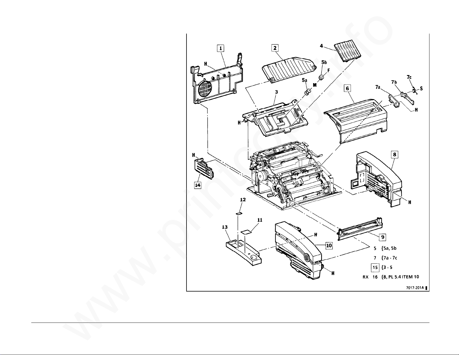
PL 1.2Covers
www.printcopy.info
www.printcopy.info
Item Part Description
1 002K79750 Rear Cover (USO)
- 002K77021 Rear Cover (RX)
- 048K95020 Rear Cover (OLV)
2 050E95812 Input Tray Extension
3 -- Input Tray/Printer Cover
(includes LH and RH
Document Guides)
4 -- Document Guide Cover
5 -- Document Guide Gear
Assembly
5a -- Document Guide Spring
5b -- Document Guide Gear
6 002E88644 Upper Scan Cover
- 002E76431 Upper Scan Cover
(OLV)
7 -- Scan Support Assembly
7a -- Scan Support Bracket
7b 031E95680 Scan Support Arm
7c 009E99800 Scan Support Spring
8 002E88693 RH Cover (USO)
- -- RH Cover (RX)
(P/O Item 16)
9 038K96243 Lower Scan Cover
10 002E88663 LH Cover (USO)
- 002E88673 LH Cover (RX)
11 091P66413 Customer Assistance
Label (USO)
12 091E77050 Telephone Number
Label (USO)
13 068E86002 Handset Cradle (USO)
14 002E88731 Coupler Cover (USO)
- 002E88741 Coupler Cover (RX)
15 002K75243 Input Tray/Printer Cover
Assembly
16 499K95949 RH Cover Kit (RX)
PL 1.2 5-4 Telecopier 7017 / 7017SF
12/88
Page 97

PL 1.3Frames
www.printcopy.info
www.printcopy.info
Item Part Description
1 -- LH Frame
*2 032E96041 Paper Side Plate #1
3 091P80361 Tag/MOD Matrix
*4 032E96051 Paper Side Plate #2
5 -- RH Frame
6 -- Serial Number Plate
7 -- Base Frame
8 -- Power Supply Housing
9 -- Base Plate
10 499K95609 Feet
10a -- Foot
11 -- CNC Guide
Telecopier 7017 / 7017SF 5-5
12/88
PL 1.3
Page 98
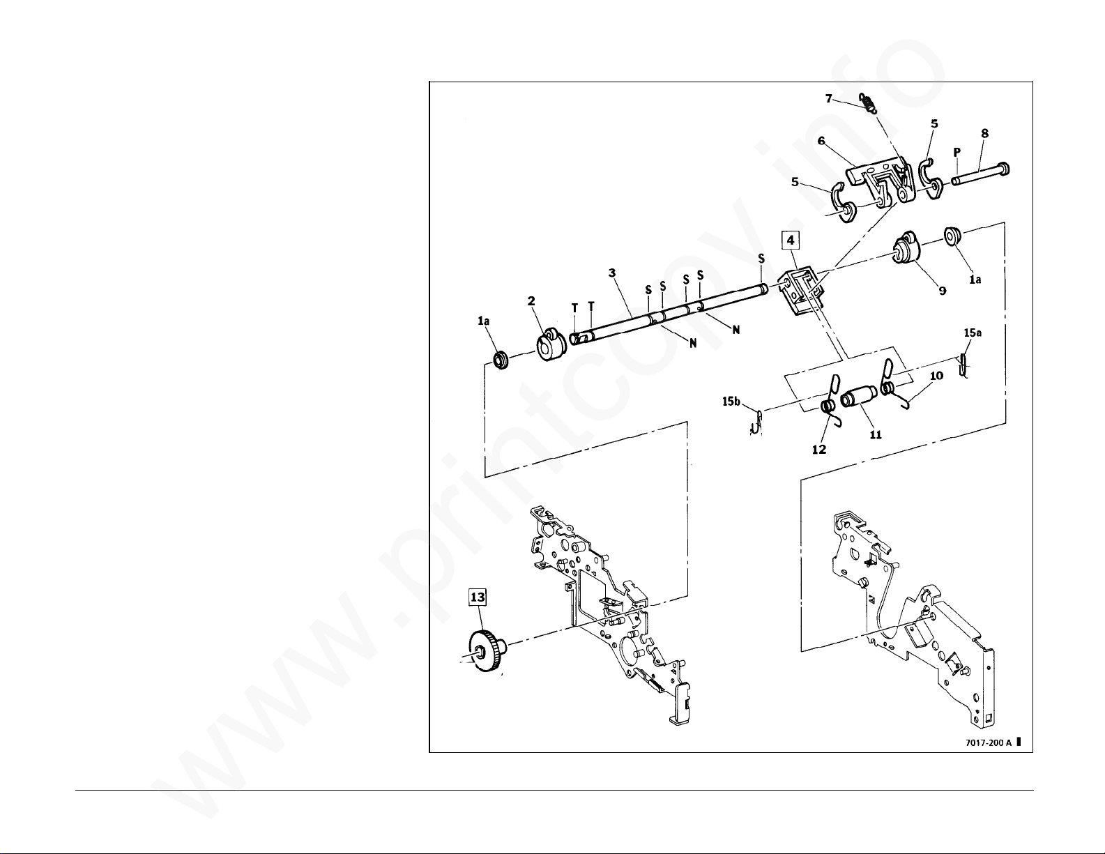
PL 2.1Upper ADF
www.printcopy.info
www.printcopy.info
Item Part Description
1 499K95601 Bearing #6 Kit
1a -- Bearing #6
2 -- LH Cam / Stopper
3 -- Retard Shaft
4 499K95613 Pad Assembly (includes
Retard Pad and Pad
Holder)
5 -- Paper Weight
6 -- Nudger Arm
7 009E98941 Nudger Arm Spring
8 -- Pad Shaft
9 -- RH Cam / Stopper
10 -- RH Retard Spring
11 -- Spring Spacer
12 -- LH Retard Spring
13 007E96870 Nudger Timing Gear
14 006K95781 Retard Assembly
15 499K95736 Spring Hook Kit
15a -- RH Hook
15b -- LH Hook
PL 2.1 5-6 Telecopier 7017 / 7017SF
12/88
Page 99
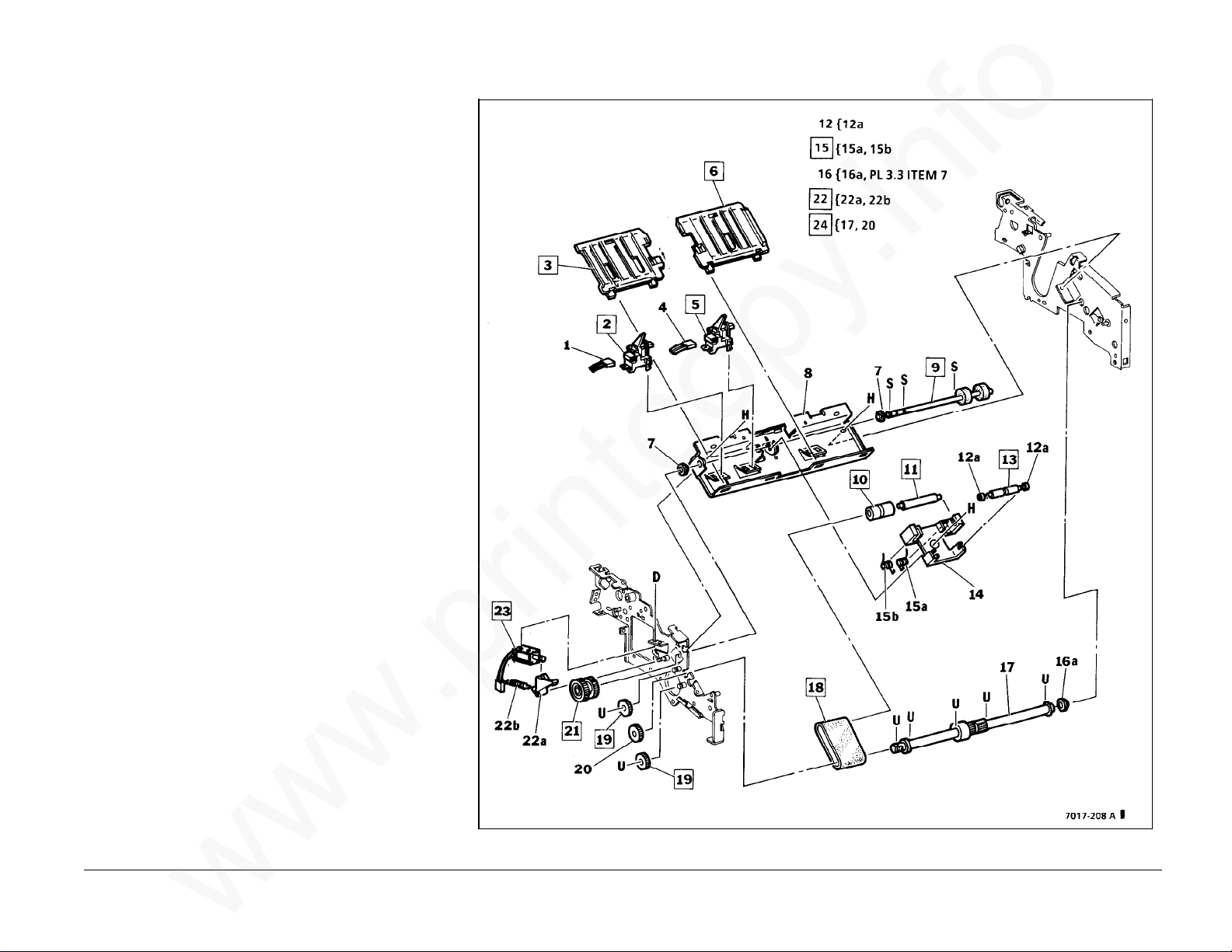
PL 2.2Lower ADF
www.printcopy.info
www.printcopy.info
Item Part Description
1 -- J402 (P/O PL 5.5 Item 12)
2 130K96530 Wide Original Sensor
*3 038E96930 LH ADF Guide
4 -- J403 (P/O PL 5.5 Item 11)
5 130K96530 Document Sensor
*6 038E96950 RH ADF Guide
7 -- Bearing #6 (P/O PL 2.1
Item 1)
8 -- ADF Bracket
9 022K85011 Nudger Roller
*10 022P62530 ADF Idler Roller
*11 006E99490 ADF Tension Shaft
12 499K95603 Stop Shaft Bearing Kit
12a -- Stop Shaft Bearing
*13 006E99480 Stop Shaft
14 -- ADF Block
15 499K95600 ADF Tension Spring Kit
15a -- RH ADF Tension Spring
15b -- LH ADF Tension Spring
16 499K95648 Plastic Bearing #8 Kit
16a -- Plastic Bearing #8
17 -- ADF Drive Shaft (with
ADF Drive Clutch)
18 023E96320 ADF Belt
*19 007E96881 ADF Idler Gear
20 -- ADF Drive Gear
21 005E96550 Nudger Clutch
(W/O Tag/MOD 5)
005K95600 Nudger Clutch
(Tag/MOD 5)
22 499K95727 Nudger Pawl Kit
22a -- Nudger Pawl
22b -- Nudger Pawl Spring
23 121E96121 Nudger Solenoid
Assembly **
24 006K95821 ADF Drive Shaft
Assembly
**
NOTE: If nudger
solenoid assembly is
replaced, discard any
spring and nylon washer
on solenoid plunger.
Telecopier 7017 / 7017SF 5-7
12/88
PL 2.2
Page 100
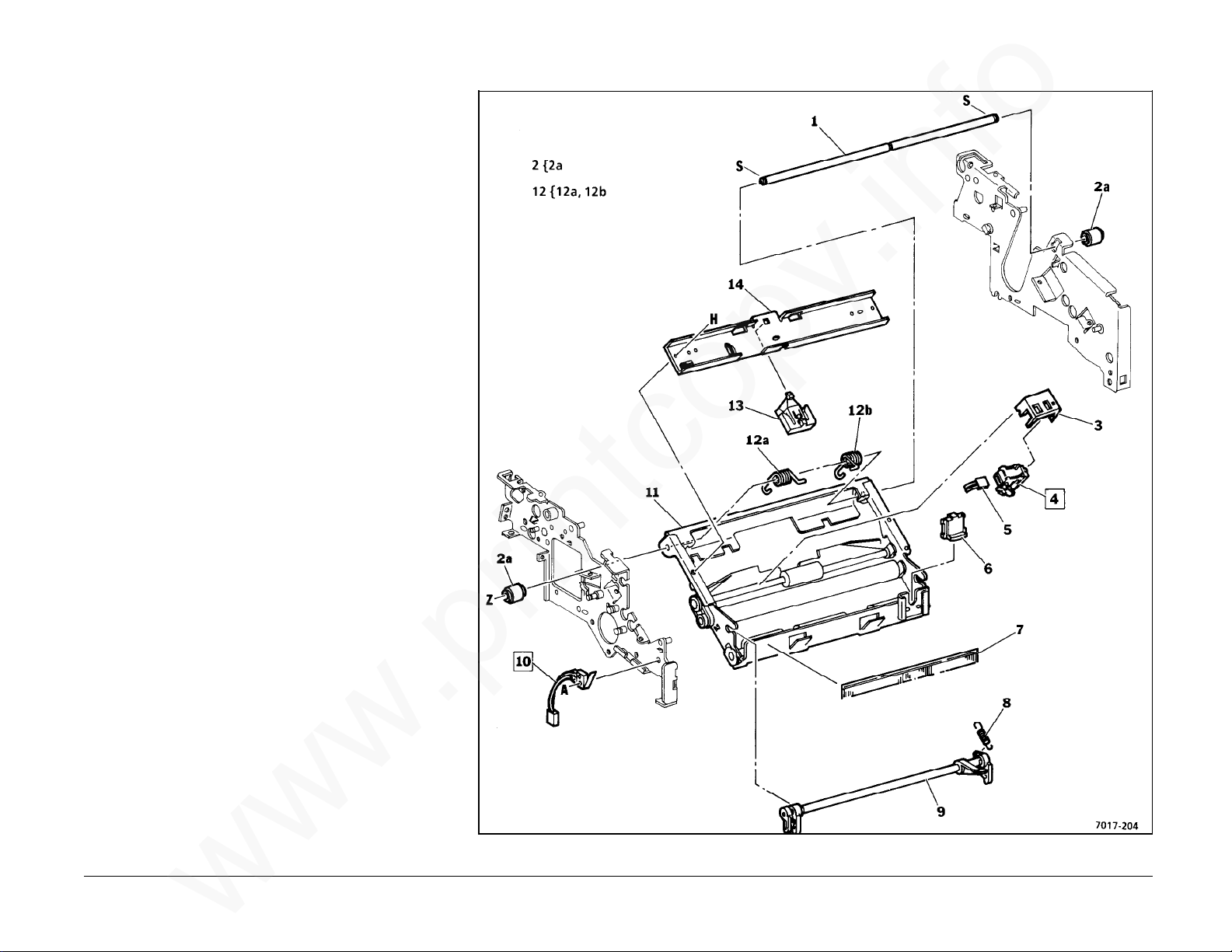
PL 3.1Upper Scan Electronics
www.printcopy.info
www.printcopy.info
Item Part Description
1 -- Scan Pivot Shaft
2 499K95606 Scan Pivot Bearing Kit
2a -- Scan Pivot Bearing
3 068E87910 Scan Sensor Bracket
4 130K96540 Scan Position Sensor
5 -- J405 (P/O PL 5.5 Item 7)
*6 003E98170 Scanner Release Bar
*7 125E95160 Upper Scan Static
Eliminator
*8 009E98920 Latch Spring
*9 003K96090 Scanner Latch
10 110K95780 Scan Interlock Switch
11 -- Upper Scan Frame
12 499K95607 Scan Pivot Spring Kit
12a -- LH Scan Pivot Spring
12b -- RH Scan Pivot Spring
13 003E98240 Retard Stop Pad
14 -- Retard Stop Bracket
PL 3.1 5-8 Telecopier 7017 / 7017SF
12/88
 Loading...