

Page 1

Xerox DocuPrint 100/115/135/180 EPS
operator
guide
701P24790
April, 2005
Page 2

Prepared by:
Xerox Corporation
Global Knowledge and Language Services
800 Philips Road Bldg. 845-17S
Webster, New York 14580
USA
©2005 by Xerox Corporation. All rights reserved.
Copyright protection claimed includes all forms and matters of copyrightable material and information
now allowed by statutory judicial law or hereinafter granted, i ncluding without limitation, material generated
from the software programs di splayed on the screen such as ic ons, screen displays, or look s.
Printed in the United States of America.
XEROX® and all Xerox product names mentioned in this publicat i on are trademarks of XEROX CORPORATION.
Other company trademark s are al so acknowledged.
Changes are periodically made to thi s document. Changes, tec hni cal inaccuracies, and
typographic errors will be corrected
in subsequent editions.
Page 3

Safety
Laser safety . . . . . . . . . . . . . . . . . . . . . . . . . . . . . . . . . . . . . . . . . . . . . . . . . . . . . . . . . . . . . . . . . . v
Ozone information: U. S. only . . . . . . . . . . . . . . . . . . . . . . . . . . . . . . . . . . . . . . . . . . . . . . . . . . . . . v
Operation safety: U. S. . . . . . . . . . . . . . . . . . . . . . . . . . . . . . . . . . . . . . . . . . . . . . . . . . . . . . . . . . . v
Operation safety: Europe . . . . . . . . . . . . . . . . . . . . . . . . . . . . . . . . . . . . . . . . . . . . . . . . . . . . . . . .vi
Warning markings . . . . . . . . . . . . . . . . . . . . . . . . . . . . . . . . . . . . . . . . . . . . . . . . . . . . . . vii
Electrical supply . . . . . . . . . . . . . . . . . . . . . . . . . . . . . . . . . . . . . . . . . . . . . . . . . . . . . . . vii
Ventilation . . . . . . . . . . . . . . . . . . . . . . . . . . . . . . . . . . . . . . . . . . . . . . . . . . . . . . . . . . . . vii
Operator accessible areas . . . . . . . . . . . . . . . . . . . . . . . . . . . . . . . . . . . . . . . . . . . . . . .viii
Maintenance . . . . . . . . . . . . . . . . . . . . . . . . . . . . . . . . . . . . . . . . . . . . . . . . . . . . . . . . . .viii
Before cleaning your product . . . . . . . . . . . . . . . . . . . . . . . . . . . . . . . . . . . . . . . . . . . . .viii
CE mark: Europe only . . . . . . . . . . . . . . . . . . . . . . . . . . . . . . . . . . . . . . . . . . . . . . . . . . . . . . . . . . viii
Radio and telecommunications equipment directive
(Europe only) . . . . . . . . . . . . . . . . . . . . . . . . . . . . . . . . . . . . . . . . . . . . . . . . . . . . . . . . . . . . . . . . .ix
For further information . . . . . . . . . . . . . . . . . . . . . . . . . . . . . . . . . . . . . . . . . . . . . . . . . . . . . . . . . . x
Introduction
About this guide . . . . . . . . . . . . . . . . . . . . . . . . . . . . . . . . . . . . . . . . . . . . . . . . . . . . . . . . . . . . . . .xi
Contents . . . . . . . . . . . . . . . . . . . . . . . . . . . . . . . . . . . . . . . . . . . . . . . . . . . . . . . . . . . . . .xi
Conventions . . . . . . . . . . . . . . . . . . . . . . . . . . . . . . . . . . . . . . . . . . . . . . . . . . . . . . . . . . .xi
Documentation . . . . . . . . . . . . . . . . . . . . . . . . . . . . . . . . . . . . . . . . . . . . . . . . . . . . . . . . . . . . . . . xii
DocuPrint 100/115/135/155/180 EPS documentation . . . . . . . . . . . . . . . . . . . . . . . . . . . xiii
Table of contents
1 Overview
Functional overview . . . . . . . . . . . . . . . . . . . . . . . . . . . . . . . . . . . . . . . . . . . . . . . . . . . . . . . . . . 1-1
Host connectivity options . . . . . . . . . . . . . . . . . . . . . . . . . . . . . . . . . . . . . . . . . . . . . . . 1-2
Data formats supported . . . . . . . . . . . . . . . . . . . . . . . . . . . . . . . . . . . . . . . . . . . . . . . . . 1-3
Stock specifications . . . . . . . . . . . . . . . . . . . . . . . . . . . . . . . . . . . . . . . . . . . . . . . . . . . . 1-3
Printing process and job flow . . . . . . . . . . . . . . . . . . . . . . . . . . . . . . . . . . . . . . . . . . . . 1-6
Printer overview . . . . . . . . . . . . . . . . . . . . . . . . . . . . . . . . . . . . . . . . . . . . . . . . . . . . . . . . . . . . . 1-8
Printer components . . . . . . . . . . . . . . . . . . . . . . . . . . . . . . . . . . . . . . . . . . . . . . . . . . . 1-10
Printer options . . . . . . . . . . . . . . . . . . . . . . . . . . . . . . . . . . . . . . . . . . . . . . . . . . . . . . . 1-16
Stock sizes . . . . . . . . . . . . . . . . . . . . . . . . . . . . . . . . . . . . . . . . . . . . . . . . . . . . 1-4
Paper weights . . . . . . . . . . . . . . . . . . . . . . . . . . . . . . . . . . . . . . . . . . . . . . . . . . 1-4
Special stocks . . . . . . . . . . . . . . . . . . . . . . . . . . . . . . . . . . . . . . . . . . . . . . . . . . 1-5
General paper characteristics to look for . . . . . . . . . . . . . . . . . . . . . . . . . . . . . 1-5
Processor Feeder Trays . . . . . . . . . . . . . . . . . . . . . . . . . . . . . . . . . . . . . . . . . 1-10
Sample tray. . . . . . . . . . . . . . . . . . . . . . . . . . . . . . . . . . . . . . . . . . . . . . . . . . . 1-10
Attention light . . . . . . . . . . . . . . . . . . . . . . . . . . . . . . . . . . . . . . . . . . . . . . . . . 1-11
Purge tray . . . . . . . . . . . . . . . . . . . . . . . . . . . . . . . . . . . . . . . . . . . . . . . . . . . . 1-11
Feeder trays . . . . . . . . . . . . . . . . . . . . . . . . . . . . . . . . . . . . . . . . . . . . . . . . . . 1-11
Stacker bins . . . . . . . . . . . . . . . . . . . . . . . . . . . . . . . . . . . . . . . . . . . . . . . . . . 1-12
Feeder/stacker modules . . . . . . . . . . . . . . . . . . . . . . . . . . . . . . . . . . . . . . . . . 1-14
Printer control console (not shown). . . . . . . . . . . . . . . . . . . . . . . . . . . . . . . . . 1-15
Printer configurations . . . . . . . . . . . . . . . . . . . . . . . . . . . . . . . . . . . . . . . . . . . 1-15
Bypass transport . . . . . . . . . . . . . . . . . . . . . . . . . . . . . . . . . . . . . . . . . . . . . . . 1-16
Support and interface with feeders . . . . . . . . . . . . . . . . . . . . . . . . . . . . . . . . . 1-17
Operator Guide
i
Page 4

Table of contents
7 by 10 inch enablement kit . . . . . . . . . . . . . . . . . . . . . . . . . . . . . . . . . . . . . . 1-18
Paper paths . . . . . . . . . . . . . . . . . . . . . . . . . . . . . . . . . . . . . . . . . . . . . . . . . . . . . . . . . 1-18
Printer paper path . . . . . . . . . . . . . . . . . . . . . . . . . . . . . . . . . . . . . . . . . . . . . . 1-18
Bypass transport paper path. . . . . . . . . . . . . . . . . . . . . . . . . . . . . . . . . . . . . . 1-20
Controller overview . . . . . . . . . . . . . . . . . . . . . . . . . . . . . . . . . . . . . . . . . . . . . . . . . . . . . . . . . . 1-20
Controller components . . . . . . . . . . . . . . . . . . . . . . . . . . . . . . . . . . . . . . . . . . . . . . . . 1-21
Sun workstation. . . . . . . . . . . . . . . . . . . . . . . . . . . . . . . . . . . . . . . . . . . . . . . . 1-21
External components and options. . . . . . . . . . . . . . . . . . . . . . . . . . . . . . . . . . 1-26
Controller stand. . . . . . . . . . . . . . . . . . . . . . . . . . . . . . . . . . . . . . . . . . . . . . . . 1-26
Online and offline interfaces . . . . . . . . . . . . . . . . . . . . . . . . . . . . . . . . . . . . . . . . . . . . 1-26
Moving the controller . . . . . . . . . . . . . . . . . . . . . . . . . . . . . . . . . . . . . . . . . . . . . . . . . . 1-27
Tape drives overview . . . . . . . . . . . . . . . . . . . . . . . . . . . . . . . . . . . . . . . . . . . . . . . . . . . . . . . . 1-29
Paper sizing and print speed . . . . . . . . . . . . . . . . . . . . . . . . . . . . . . . . . . . . . . . . . . . . . . . . . . 1-30
Long and short edge feeding . . . . . . . . . . . . . . . . . . . . . . . . . . . . . . . . . . . . . . . . . . . 1-31
Paper width and throughput speed (LCDS printing only) . . . . . . . . . . . . . . . . . . . . . . 1-31
Paper size and pitch mode minimum and maximum . . . . . . . . . . . . . . . . . . . . . . . . . 1-33
Feed direction for standard paper sizes . . . . . . . . . . . . . . . . . . . . . . . . . . . . . . . . . . . 1-35
2 Managing the printer
Controlling the printer . . . . . . . . . . . . . . . . . . . . . . . . . . . . . . . . . . . . . . . . . . . . . . . . . . . . . . . . . 2-1
Interrupting printing . . . . . . . . . . . . . . . . . . . . . . . . . . . . . . . . . . . . . . . . . . . . . . . . . . . . 2-1
Resuming printing . . . . . . . . . . . . . . . . . . . . . . . . . . . . . . . . . . . . . . . . . . . . . . . . . . . . . 2-1
Powering on the printer . . . . . . . . . . . . . . . . . . . . . . . . . . . . . . . . . . . . . . . . . . . . . . . . . 2-1
Powering off the printer . . . . . . . . . . . . . . . . . . . . . . . . . . . . . . . . . . . . . . . . . . . . . . . . . 2-1
Powering off the printer immediately . . . . . . . . . . . . . . . . . . . . . . . . . . . . . . . . . . . . . . . 2-2
Adjusting the registration transport roll levers for heavy paper . . . . . . . . . . . . . . . . . . . 2-2
Loading paper . . . . . . . . . . . . . . . . . . . . . . . . . . . . . . . . . . . . . . . . . . . . . . . . . . . . . . . . . . . . . . 2-3
Unloading a stacker bin . . . . . . . . . . . . . . . . . . . . . . . . . . . . . . . . . . . . . . . . . . . . . . . . . . . . . . . 2-8
3 Managing the system
Starting, stopping, and rebooting the system . . . . . . . . . . . . . . . . . . . . . . . . . . . . . . . . . . . . . . . 3-1
Powering on the controller . . . . . . . . . . . . . . . . . . . . . . . . . . . . . . . . . . . . . . . . . . . . . . 3-1
Powering on the printer . . . . . . . . . . . . . . . . . . . . . . . . . . . . . . . . . . . . . . . . . . . . . . . . . 3-1
Holding queues . . . . . . . . . . . . . . . . . . . . . . . . . . . . . . . . . . . . . . . . . . . . . . . . . . . . . . . 3-2
Releasing queues . . . . . . . . . . . . . . . . . . . . . . . . . . . . . . . . . . . . . . . . . . . . . . . . . . . . . 3-2
Rebooting the system (warm boot) . . . . . . . . . . . . . . . . . . . . . . . . . . . . . . . . . . . . . . . . 3-2
Performing a deferred shutdown and reboot . . . . . . . . . . . . . . . . . . . . . . . . . . . . . . . . . 3-3
Performing an immediate shutdown and reboot . . . . . . . . . . . . . . . . . . . . . . . . . . . . . . 3-3
Restarting the DocuSP software . . . . . . . . . . . . . . . . . . . . . . . . . . . . . . . . . . . . . . . . . . 3-4
Powering off the system . . . . . . . . . . . . . . . . . . . . . . . . . . . . . . . . . . . . . . . . . . . . . . . . 3-4
Performing an emergency power off. . . . . . . . . . . . . . . . . . . . . . . . . . . . . . . . . 3-5
Powering off the controller . . . . . . . . . . . . . . . . . . . . . . . . . . . . . . . . . . . . . . . . 3-5
Powering off the printer . . . . . . . . . . . . . . . . . . . . . . . . . . . . . . . . . . . . . . . . . . . 3-6
Operating the 18/36 track tape drive . . . . . . . . . . . . . . . . . . . . . . . . . . . . . . . . . . . . . . . . . . . . . 3-7
Powering on the tape drive . . . . . . . . . . . . . . . . . . . . . . . . . . . . . . . . . . . . . . . . . . . . . . 3-7
Powering off the tape drive . . . . . . . . . . . . . . . . . . . . . . . . . . . . . . . . . . . . . . . . . . . . . . 3-8
Placing the tape drive online . . . . . . . . . . . . . . . . . . . . . . . . . . . . . . . . . . . . . . . . . . . . . 3-9
Loading a tape . . . . . . . . . . . . . . . . . . . . . . . . . . . . . . . . . . . . . . . . . . . . . . . . . . . . . . . 3-9
Unloading a tape . . . . . . . . . . . . . . . . . . . . . . . . . . . . . . . . . . . . . . . . . . . . . . . . . . . . . 3-10
Guidelines for handling cartridges . . . . . . . . . . . . . . . . . . . . . . . . . . . . . . . . . . . . . . . . 3-11
Setting file protection . . . . . . . . . . . . . . . . . . . . . . . . . . . . . . . . . . . . . . . . . . . . . . . . . . 3-12
Printing the online Help documentation . . . . . . . . . . . . . . . . . . . . . . . . . . . . . . . . . . . . . . . . . . 3-13
ii Operator Guide
Page 5

4 Maintaining the system
Paper care . . . . . . . . . . . . . . . . . . . . . . . . . . . . . . . . . . . . . . . . . . . . . . . . . . . . . . . . . . . . . . . . . 4-1
Storing paper . . . . . . . . . . . . . . . . . . . . . . . . . . . . . . . . . . . . . . . . . . . . . . . . . . . . . . . . . 4-1
Conditioning paper . . . . . . . . . . . . . . . . . . . . . . . . . . . . . . . . . . . . . . . . . . . . . . . . . . . . 4-3
Paper curl . . . . . . . . . . . . . . . . . . . . . . . . . . . . . . . . . . . . . . . . . . . . . . . . . . . . . . . . . . . 4-3
Using consumables . . . . . . . . . . . . . . . . . . . . . . . . . . . . . . . . . . . . . . . . . . . . . . . . . . . . . . . . . . 4-4
Adding fuser agent . . . . . . . . . . . . . . . . . . . . . . . . . . . . . . . . . . . . . . . . . . . . . . . . . . . . 4-4
Replacing the dry ink waste container . . . . . . . . . . . . . . . . . . . . . . . . . . . . . . . . . . . . . 4-7
Replacing the dry ink cartridge . . . . . . . . . . . . . . . . . . . . . . . . . . . . . . . . . . . . . . . . . . 4-11
Using the custom transfer assist blade . . . . . . . . . . . . . . . . . . . . . . . . . . . . . . . . . . . . 4-13
Cleaning the system and its components . . . . . . . . . . . . . . . . . . . . . . . . . . . . . . . . . . . . . . . . . 4-14
Cleaning the 18/36-track cartridge tape drive . . . . . . . . . . . . . . . . . . . . . . . . . . . . . . . 4-15
Cleaning the 26-track cartridge tape drive . . . . . . . . . . . . . . . . . . . . . . . . . . . . . . . . . 4-15
Cleaning the DVD drive . . . . . . . . . . . . . . . . . . . . . . . . . . . . . . . . . . . . . . . . . . . . . . . . 4-16
Cleaning the diskette drive . . . . . . . . . . . . . . . . . . . . . . . . . . . . . . . . . . . . . . . . . . . . . 4-16
Cleaning the sensors and the reflecting surfaces . . . . . . . . . . . . . . . . . . . . . . . . . . . . 4-16
Cleaning the Q850 sensor . . . . . . . . . . . . . . . . . . . . . . . . . . . . . . . . . . . . . . . 4-16
Cleaning the Q1011 sensor and mirror. . . . . . . . . . . . . . . . . . . . . . . . . . . . . . 4-18
Cleaning additional sensors . . . . . . . . . . . . . . . . . . . . . . . . . . . . . . . . . . . . . . 4-19
Cleaning the display . . . . . . . . . . . . . . . . . . . . . . . . . . . . . . . . . . . . . . . . . . . . . . . . . . 4-22
Cleaning the exterior surfaces of the system . . . . . . . . . . . . . . . . . . . . . . . . . . . . . . . 4-22
Table of contents
5 Troubleshooting
Undeclared faults . . . . . . . . . . . . . . . . . . . . . . . . . . . . . . . . . . . . . . . . . . . . . . . . . . . . . . . . . . . . 5-1
Problem classifications . . . . . . . . . . . . . . . . . . . . . . . . . . . . . . . . . . . . . . . . . . . . . . . . . 5-1
Troubleshooting client problems . . . . . . . . . . . . . . . . . . . . . . . . . . . . . . . . . . . . . . . . . . 5-2
Solving FreeFlow Prepress problems . . . . . . . . . . . . . . . . . . . . . . . . . . . . . . . . 5-2
Troubleshooting Graphical User Interface (GUI) problems . . . . . . . . . . . . . . . . . . . . . . 5-2
Troubleshooting print quality problems . . . . . . . . . . . . . . . . . . . . . . . . . . . . . . . . . . . . . 5-3
Resolving print quality problems on a PostScript job . . . . . . . . . . . . . . . . . . . . 5-3
Isolating and resolving printer-driven print quality problems. . . . . . . . . . . . . . . 5-4
Resolving font problems . . . . . . . . . . . . . . . . . . . . . . . . . . . . . . . . . . . . . . . . . . . . . . . . 5-4
Troubleshooting job flow problems . . . . . . . . . . . . . . . . . . . . . . . . . . . . . . . . . . . . . . . . 5-5
Troubleshooting job integrity problems . . . . . . . . . . . . . . . . . . . . . . . . . . . . . . . . . . . . . 5-5
Troubleshooting PDL problems . . . . . . . . . . . . . . . . . . . . . . . . . . . . . . . . . . . . . . . . . . . 5-6
Isolating HP PCL file problems . . . . . . . . . . . . . . . . . . . . . . . . . . . . . . . . . . . . . 5-6
Isolating PostScript file problems . . . . . . . . . . . . . . . . . . . . . . . . . . . . . . . . . . . 5-6
Isolating TIFF file problems. . . . . . . . . . . . . . . . . . . . . . . . . . . . . . . . . . . . . . . . 5-7
Isolating PDF file problems. . . . . . . . . . . . . . . . . . . . . . . . . . . . . . . . . . . . . . . . 5-8
Troubleshooting process problems . . . . . . . . . . . . . . . . . . . . . . . . . . . . . . . . . . . . . . . . 5-8
Troubleshooting productivity and performance problems . . . . . . . . . . . . . . . . . . . . . . . 5-9
Troubleshooting problems with saving jobs . . . . . . . . . . . . . . . . . . . . . . . . . . . . . . . . 5-10
Crash recovery . . . . . . . . . . . . . . . . . . . . . . . . . . . . . . . . . . . . . . . . . . . . . . . . . . . . . . . . . . . . . 5-10
Streaming mode . . . . . . . . . . . . . . . . . . . . . . . . . . . . . . . . . . . . . . . . . . . . . . . . . . . . . 5-10
UI recovery messages . . . . . . . . . . . . . . . . . . . . . . . . . . . . . . . . . . . . . . . . . . 5-11
Recovery message examples. . . . . . . . . . . . . . . . . . . . . . . . . . . . . . . . . . . . . 5-11
Spooling mode . . . . . . . . . . . . . . . . . . . . . . . . . . . . . . . . . . . . . . . . . . . . . . . . . . . . . . 5-12
Points to note . . . . . . . . . . . . . . . . . . . . . . . . . . . . . . . . . . . . . . . . . . . . . . . . . 5-12
Clearing online print data . . . . . . . . . . . . . . . . . . . . . . . . . . . . . . . . . . . . . . . . . . . . . . 5-13
Online gateway faults/submitting a job from the host . . . . . . . . . . . . . . . . . . . . . . . . . . . . . . . . 5-13
Obtaining information about a job . . . . . . . . . . . . . . . . . . . . . . . . . . . . . . . . . . . . . . . . 5-14
Data type on the Online Manager window . . . . . . . . . . . . . . . . . . . . . . . . . . . . . . . . . 5-15
Streaming queue release setup . . . . . . . . . . . . . . . . . . . . . . . . . . . . . . . . . . . . . . . . . 5-15
Incorrect printer state on host . . . . . . . . . . . . . . . . . . . . . . . . . . . . . . . . . . . . . . . . . . . 5-15
Operator Guide iii
Page 6

Table of contents
Clearing paper jams . . . . . . . . . . . . . . . . . . . . . . . . . . . . . . . . . . . . . . . . . . . . . . . . . . . . . . . . . 5-15
Aids to paper jam clearance . . . . . . . . . . . . . . . . . . . . . . . . . . . . . . . . . . . . . . . . . . . . 5-16
Clearing paper jams in all printer areas . . . . . . . . . . . . . . . . . . . . . . . . . . . . . . . . . . . 5-16
Checking job integrity following a paper jam . . . . . . . . . . . . . . . . . . . . . . . . . . . . . . . . 5-17
Clearing paper jams in printer areas 2 through 20 . . . . . . . . . . . . . . . . . . . . . . . . . . . 5-18
Clearing a paper jam in the bypass transport . . . . . . . . . . . . . . . . . . . . . . . . . . . . . . . 5-29
Clearing a misfeed (feeder tray fault) . . . . . . . . . . . . . . . . . . . . . . . . . . . . . . . . . . . . . 5-31
Troubleshooting frequent misfeeds (processor feeder trays) . . . . . . . . . . . . . . . . . . . 5-33
Incorrect paper size message . . . . . . . . . . . . . . . . . . . . . . . . . . . . . . . . . . . . . . . . . . . 5-36
Generating a test page . . . . . . . . . . . . . . . . . . . . . . . . . . . . . . . . . . . . . . . . . . . . . . . . . . . . . . . 5-36
Troubleshooting stacker problems . . . . . . . . . . . . . . . . . . . . . . . . . . . . . . . . . . . . . . . . . . . . . . 5-37
Troubleshooting paper curl problems . . . . . . . . . . . . . . . . . . . . . . . . . . . . . . . . . . . . . . . . . . . . 5-37
Checking paper curl . . . . . . . . . . . . . . . . . . . . . . . . . . . . . . . . . . . . . . . . . . . . . . . . . . 5-37
Adjusting the decurler lever . . . . . . . . . . . . . . . . . . . . . . . . . . . . . . . . . . . . . . . . . . . . . 5-40
Troubleshooting the 36-track tape drive . . . . . . . . . . . . . . . . . . . . . . . . . . . . . . . . . . . . . . . . . . 5-41
Performing basic recovery . . . . . . . . . . . . . . . . . . . . . . . . . . . . . . . . . . . . . . . . . . . . . 5-41
Troubleshooting initial program load (IPL) failure . . . . . . . . . . . . . . . . . . . . . . . . . . . . 5-41
Solving other cartridge tape drive problems . . . . . . . . . . . . . . . . . . . . . . . . . . . . . . . . 5-42
Calling for service . . . . . . . . . . . . . . . . . . . . . . . . . . . . . . . . . . . . . . . . . . . . . . . . . . . . . . . . . . . 5-45
6 Supplies
Index
Available supplies . . . . . . . . . . . . . . . . . . . . . . . . . . . . . . . . . . . . . . . . . . . . . . . . . . . . . . . . . . . . A-1
How to order supplies . . . . . . . . . . . . . . . . . . . . . . . . . . . . . . . . . . . . . . . . . . . . . . . . . . . . . . . . . A-5
iv Operator Guide
Page 7

Laser safety
Safety
WARNING: Adjustments, use of controls, or performance of
procedures other than those specified herein may result in
hazardous light exposure.
The Xerox DocuPrint printers are certifi ed to comply with the
performance standards of the U.S. Department of Health,
Education, and Welfare for Class 1 laser products. Class 1 laser
products do not emit hazardous radiation. The DocuPrint printers
do not emit hazardous radiation because the laser beam is
completely enclosed during all modes of customer operation.
The laser danger labels on the system are for Xerox service
representatives and are on or near panels or sh ields that must be
removed with a tool.
DO NOT REMOVE LABELED PANELS OR PANELS NEAR
LABELS. ONLY XEROX SERVICE REPRESENTATIVES HAVE
ACCESS TO THESE PANELS.
Ozone information: U. S. only
This product produces ozone during normal operati on. The
amount of ozone produced depends on copy volume. Ozone is
heavier than air. The environmental p arameters specified in the
Xerox installation i nstructi ons ensure th at concent ration l evels are
within safe limits. If you need additional information concerning
ozone, call 1-800-828-6571 to request the Xerox publication
600P83222, OZONE.
Operation safety: U. S.
Your Xerox equipment and supplies have been designed and
tested to meet strict safety requirements. They have been
Operator Guide
v
Page 8

Safety
approved by safety agencies, and they comply with environment al
standards. Please observe the following precautions to ensure
your continued safety.
WARNING: Improper connection of the equipment grounding
conductor may result in risk of electrical shock.
• Always connect equipment to a properly grounded elect ri cal
outlet. If in doubt, have the outlet checked by a qualified
electrician.
• Never use a ground adapter plug to connect equipment to an
electrical outlet that lacks a ground connection terminal.
• Always place equipment on a solid support surface with
adequate strength for its weigh t.
• Always use materials and supplies specifically designed for
your Xerox equipment. Use of unsuit able materials may result
in poor performance and may create a hazardous situation.
• Never move either the printer or the controller without first
contacting Xerox for approval.
• Never attempt any maintenance that is not specifically
described in this documentation.
• Never remove any covers or guards that are fastened with
screws. There are no operator-serviceable areas within these
covers.
• Never override electrical or mechanical interlocks.
• Never use supplies or cleaning materials for other than their
intended purposes. Keep all materials out of the reach of
children.
• Never operate the equipment if you notice unusual noises or
odors. Disconnect the power cord f rom the electrical outlet and
call service to correct the problem.
If you need any additional safety information concerning the
equipment or materials Xerox supplies, call Xerox Product Safety
at the following toll-free number in the United St ates:
1-800-828-6571
For customers outside the United States, contact your local Xerox
representative or operating company.
Operation safety: Europe
This Xerox product and supplies are manufactured, tested and
certified to strict safety regulations, electromagnetic regulations
and established environmental standards.
Any unauthorised alteration, whic h may include the addition of
new functions or connection of external devices, may impact the
product certification.
vi Operator Guide
Page 9
Please contact your Xerox representative for more information.
Wa rning markings
All warning instructions marked on or suppli ed with the product
should be followed.
This WARNING alerts users to areas of the produc t where there is
the possibility of personal damage.
This WARNING alerts users to areas of the product where there
are heated surfaces, which should not be touched.
Electrical supply
Safety
Ventilation
This product shall be operated from the type of elec trical supply
indicated on the product’s data plate label . If you are not sure that
your electrical supply meets the req uirements, please consul t your
local power company for advice.
WARNING
This product must be connected to a protective eart h cir cuit. This
product is supplied with a plug that has a protectiv e earth pi n. This
plug will fit only into an earthed electrical outlet. This is a safety
feature. Always connect equipment to a properly grounded
electrical outlet. If in doubt, have the outlet checked by a qualified
electrician.
To disconnect all electrical power to the product, the disconnect
device is the power cord. Remove the plug from the electrical
outlet.
Slots and opening in the enclosure of the product are provided for
ventilation. Do not block or cover the ventilation vents, as this
could result in the product overheati ng.
This product should not be placed in a built-in installation unless
proper ventilation is provided, please contact your Xerox
representative for advice.
Operator Guide vii
Page 10

Safety
Never push objects of any kind into the ventilation vents of the
product.
Operator accessible areas
This product has been designed to rest rict operator access to safe
areas only. Operator access to hazardous areas is restricted with
covers or guards, which would require a tool to remove. Never
remove these covers or guards.
Maintenance
Any operator product maintenanc e procedures will be descr ibed in
the user documentation supplied with the product. Do not carry
out any maintenance on the product, which is not descr ibed in t he
customer documentation.
Before cleaning your product
CE mark: Europe only
Before cleaning this pro duct, unplug the product from the el ectrical
outlet. Always use materials specifi cally designated for this
product, the use of other materi als may result in po or performance
and may create a hazardous situation. Do not use aerosol
cleaners, they may be flammable under certain circumstances.
January 1, 1995: Council Directive 73/23/EEC, amended by
Council Directive 93/68/EEC, approximation of the laws of the
member states related to low voltage equipment.
January 1, 1996: Council Directive 89/336/EEC, appr oximation of
the laws of the member states related to electromagnetic
compatibility.
March 9, 1999: Council Directi ve 99/5/EC, on radio equipment and
telecommunications terminal equipment and the mutual
recognition of their conformity.
A full declaration of conformity, defining the relevant directives and
referenced standards, can be obtained from your Xerox
representative.
In order to allow this equipment to operate in proximity to
Industrial, Scientific and Medical (ISM) equipment, the external
viii Operator Guide
Page 11

radiation for the ISM equipment may have to be limited or special
mitigation measures taken.
This is a Class A product. In a domestic environment thi s product
may cause radio frequency interference, in which case the user
may be required to take adequate measures.
Shielded interface cables must be used with this product to
maintain compliance with Council Dir ective 89/36/EEC.
Radio and telecommunications equipment directive (Europe only)
Certification to 1999/5/EC Radio Equipment and
Telecommunications Terminal Equipment Directive:
This Xerox product has been self-certified by Xerox for panEuropean single terminal connection to the analog publi c switched
telephone network (PSTN) in accordance with Directive 1999/5/
EC.
Safety
The product has been designed to work with the national PSTNs
and compatible PBXs of the following countries:
• Austria • Germany • Luxembourg • Sweden
• Belgium • Greece • Netherlands • Switzerland
• Denmark • Icel and • Norway • United Kingd om
• Finland • Ireland • Portugal
• France • Italy • Spain
In the event of problems, contact your local Xerox representative
in the first instance.
This product has been tested to, and is compliant wit h, TBR21, a
specification for terminal equipment for use on analog switched
telephone networks in the European Economic area.
The product may be configured to be compatible with other
country networks. Please contact your Xerox representative if
your product needs to be reconnected to a network in another
country. This product has no user-adjustable settings.
NOTE: Although this product can use either loop disconnect
(pulse) or DTMF (tone) signaling, it should be set to use DTMF
signaling. DTMF signaling provides reliabl e and faster call setup.
Modification or connection to external control software, or to
external control apparatus not authorized by Xerox, inval idat es its
certification.
Operator Guide ix
Page 12

Safety
For further information
For more information on Environment, Health and Safety in
relation to this Xerox product and supplies, please contact the
following customer help lines:
Europe: +44 1707 353434
USA: 1 800 8286571
Canada: 1 800 8286571
x Oper ator Guide
Page 13

About this guide
Contents
Introduction
This document provides information on how to perform operator
tasks for the DocuPrint 100/115/135/155/180 Enterprise Printing
System (EPS).
Before using this documentat ion, become familiar wit h its content s
and conventions.
This guide contains the following:
• Chapter 1, “Overview,” provides a functional overview of the
system; describes the controller and printer components; and
explains the printing process, and the job flow.
• Chapter 2, “Managing the printer,” provides information
specific to the printer, including management of paper stock
and programming of the various trays.
• Chapter 3, “Managing the system,” provides managementrelated information that pertains to the system as a whole,
such as starting, stopping, and rebooting the system and
operating the tape drives.
• Chapter 4, “Maintaining the system,” provides information on
adding and replacing consumable supplies, such as dry ink,
and on cleaning the vari ous ar eas of th e sys tem, i ncludi ng the
tape drives.
• Chapter 5, “Troubleshooting,” provides information that will
assist users in solving problems.
• Appendix A, “Supplies,” provides a summary of the pap er that
are used most often and the necessary supplies, their order
numbers, and how to order them from Xerox.
• An index is provided at the end of this document.
Conventions
Operator Guide
This guide uses the following conventions :
xi
Page 14

Introduction
• Initial capita l and an gle brackets: Within procedures, the
names of keys are shown with an initial capital and within
angle brackets (for example, pr ess <Enter>).
• Angle brackets: Variable information, or the position of a
specified argument in the command syntax, appears in angle
brackets (for example, List Fonts <pattern>).
• Fixed pitch font: Within procedures, text and numbers that
you enter are shown in a bold, fixed pit ch (“computer”) font (for
example, enter privilege operator).
• Messages that appear on the controller screen are shown in
the medium weight fixed pitch font (for example, Online
Gateway disabled).
• The word “enter” within procedures: The two-step process
of keying in data and pressing <Enter> (for example, enter y).
• Italics: Document and library names are shown in italics (for
example, the Xerox DocuPrint NPS/IPS Guide to Managing
Print Jobs).
Variable elements in a command or directory path are also
shown in italics (for example, var/spool/XRXnps/ filename).
Documentation
• Vertical bars: Alternatives to specified arguments are
separated by vertical bars (f or example, Set Time <Time |
Remote Host Name | IP Address>).
NOTE: Notes are hints that help you perform a task or under stand
the text.
CAUTION: Cautions alert you to an action that could damage
hardware or software.
WARNING: Warnings alert you to conditions that may affect the
safety of people.
This section lists related publications.
xii Operator Guide
Page 15

DocuPrint 100/115/135/155/180 EPS documentation
The following documents cont ain information on the Xerox
DocuPrint 100/115/135/155/180 EPS:
• Customer Documentation CD
• Xerox DocuPrint 100/115/135/155/180 EPS Operator Guide
• Xerox Document Services Platform Using LCDS Print
Description Language
• Xerox DocuPrint 100/115/135/155/180 EPS Installation
Planning Guide
• Xerox DocuPrint 100/115/135/155/180 EPS NPS/IPS
Extension Operations Guide
• Xerox DocuPrint EPS Font Reference Manual
• Xerox DocuPrint 100/115/135/155/180 EPS Operator Quick
Reference Card
• Xerox DocuPrint 100/115/135/155/180 EPS Customer
Information Quick Reference Card
Introduction
• Xerox DocuPrint 100/115/135/155/180 EPS Job Submission
Quick Reference Card
• Xerox Document Services Platform System Gu ide
Operator Guide xiii
Page 16

Introduction
xiv Operator Guide
Page 17

1 Overview
Functional overview
This chapter provides a functional overview of the enti re system,
as well as an overview of the controller and t he printer portions of
the system.
The Xerox DocuPrint 100/115/135/155/180 EPS prints high
quality, high resolution monochrome documents in simplex or
duplex mode at high production speeds, from LCDS, PostScript,
PCL, and other data streams. The system can switch between
printing differ ent types of data streams without a need for
rebooting or reconfiguring software.
The printer supports:
• Duplex printing
• Media handling of multiple weights, sizes, and types
• Optional modules for enhanced finishing and output to thirdparty finishing devices
• Optional enabling of a third-party roll feeder
• Optional high-capac it y feeder/stacker modules, which provide
additional feeder trays and output bins
• High resolution of LCDS, PostScript, and PCL data streams
(shown in the following table)
Table 1-1 Data stream resolution
Data
stream
LCDS 300 by 300 dpi 600 x 2400 dpi 600 by 600 dpi
PostScript
and PCL
IPDS* 240 by 240 dpi* or
Input resolution
300 by 300 dpi or
600 by 600 dpi
300 by 300 dpi or
600 by 600 dpi**
Print resolution:
DP155 and DP180
600 x 2400 dpi 600 by 600 dpi
600 x 2400 dpi 600 by 600 dpi
Print resolution:
DP100, DP115,
and DP135
* Requires additional equipment to enable.
** 600 by 600 dpi input resolution supported for full page IOCA
only
Operator Guide 1-1
Page 18

Overview
QTC
Host connectivity options
The Xerox DocuPrint 100/115/135/155/180 EPS can receive data
from a host in the following ways:
• Over a channel with bus and tag cable connection
• Through a network interface, using Novell, TCP/IP, or
AppleTalk protocols
Your system may have one or both of these configurations.
Figure 1-1 Configurations supported for the Xerox DocuPrint
100/115/135/155/180 EPS
1. Sun UNIX client workstation
2. Apple Macintosh client workstation
3. Network connection
4. Controller
5. PC client workstation
6. Mainframe host computer
7. Bus and tag cables (channel connection)
8. Printer
1-2 Operator Guide
Page 19

Data formats supported
The Xerox DocuPrint 100/115/135/155/180 EPS can print the
following data formats:
• ASCII
• LCDS
• PCL
• PDF
•PostScript
• TIFF
• IPDS
• PPML
The system prints LCDS data from a mainframe host compu ter,
emulating an IBM 4245 or 3211 page printer. The printing system
can receive data over a channel through bus and tag cables, and
through the Socket Gateway or lpr using TCP/IP protocol.
The system also prints PostScript and PCL data submitted over a
network (Ethernet or AppleTalk) from a variety of clients:
Overview
• PCs (Windows and Windows NT)
• Sun workstations (UNIX)
• UNIX command line clients: lp and lp
• NetWare Q-Server through a Novell print server (bindery
mode only)
• Apple Macintosh workstations
Stock specifications
The success of any print run depends on proper selection, care,
and handling of the paper or other stock that is used. It is very
important to select, sto re, condit ion, and l oad print medi a properly
in order to keep your printer running at optimum efficiency.
Operator Guide 1- 3
Page 20

Overview
The printer functions best and produces the best prin t quality
when using stocks that have the correct:
•Size
• Weight
•Type
• Color
For more comprehensive information on paper stocks for Xerox
printers, refer to Helpful Facts about Paper.
Stock sizes
The Xerox DocuPrint 100/115/135/155/180 EPS supports the
following sizes of stock:
Table 1-2 Stock sizes
Name of
stock
US Letter 8.5 by 11 inches 216 by 279 mm
US Legal 8.5 by 14 inches 216 by 356 mm
US Ledger
US Tabloid
A3
A4
B4
(European)
JIS B4
(Japanese)
––
B5
Size in inches Size in millimeters
11 by 17 inches
17 by 11 inches
11.69 by 16.54
inches
8.27 by 11.69
inches
9.84 by 13.89
inches
10.12 by 14.33
inches
7 by 10 inches 178 by 254 mm With 7 by 10 inch
7.17 by 10.12
inches
279 by 432 mm
432 by 279 mm
297 by 420 mm
210 by 297 mm
250 by 353 mm
257 by 364 mm
182 by 257 mm With 7 by 10 inch
NOTE: To feed papers smaller than 8 inches / 203.2 mm in width,
a 7 by 10 inch paper option kit must be instal led.
Special
requirements
option kit
option kit
Paper weights
The DP 100/1 15/135/155/ 180 EPS supports the f ollowing range of
paper weights:
16–110 pound / 60–200 gsm
Other paper weights should not be used.
1-4 Operator Guide
Page 21

NOTE: The equivalent grams per square meter of 20 pound p aper
is actually 75 gsm. However, there is no standard 75 gsm paper.
The available stock that is closest in weight to 20 pound paper is
80 gsm.
Special stocks
The following special stocks can be used with the DP 100/115/
135/155/180 EPS:
• Labels: Must be the type designed for high-speed pr inters and
must meet the specifications described in the secti on above.
Loading instructions are print ed o n all paper trays.
• Transparencies: Must be the type designed for high-speed
printers and must meet the specifications described in the
section above. Loading instructions are pr inted on all paper
trays.
• Colored paper: Available in a variety of colors, colored paper
has many uses, including calling attentio n to certain printed
material, separati ng special sections, or dividing chapt ers of a
report.
Overview
• Preprinted paper: May be letterhead, forms, or logos. (Refer
to Helpful Facts about Paper to verify that the preprinting inks
used on your stock are the kind formulated for use in laser
printers.)
• Predrilled pa per: Has holes for use i n binders or b inder rings .
Before loading predrilled paper, fan it to remove any loose
plugs that could cause paper jams.
• Perforated paper
• Precut or full tabs
• Carbonless paper
General paper characteristics to look for
When selecting paper, look for the following:
• Low moisture content (a paper to moisture ratio below 5.7
percent). Paper with higher moisture content may curl and
jam.
• Smooth surface
• Moisture resistant wrapping
• No defects such as bent edges or uneven surfaces
• Grain runs parallel with the long side of paper
Operator Guide 1- 5
Page 22

Overview
Printing process and job flow
This section describes how the system softwar e processes are
used as a typical job flows through the system.
Figure 1-2 Job flow
1. Job
2. Input Queue
3. Decomposer
4. Output queue
5. Printer
Refer to the Job Flow diagram above for the following work flow
process.
1. Job: The job and the job ticket (if applicable) are received from
the network by one of the protocol gateways.
2. Input queue: The Job Pool Manager (JPM) process transfers
the job into the input queue. The virtual printer name and job
attributes are attac hed to the job. The job remains in the Input
Queue until it can be printed; for example, “held” and “faulted”
jobs reside in the input queue.
3. Decomposer: The Job Chooser (DC process) reconciles the
job attributes with the virtual printer attributes. Once the job i s
ready for print, the Job Chooser gives the job to the
appropriate decomposer (ps_cdf pr ocess, pcl_cdf process).
4. Output queue: After decomposition, the job is stored in the
output queue.
5. Printer: The marker (marker process) transfers the job from
the Output Queue to the Image Output Terminal (IOT or
1-6 Operator Guide
Page 23

Overview
printer). After the job has successfully printed, it is removed
from the Output Queue and also from the Input Queue, if the
Input Property for the queue is set to spool.
The ps –e or ps –ef commands can be used to list the system
software processes. A varying process identification number is
listed along with each process.
NOTE: The printing process and job flow is different for
PostScript, PCL, TIFF, ASCII, PDF jobs (that is, non-LCDS jobs)
and for LCDS jobs.
PostScript, PCL,
TIFF, ASCII, and PDF
jobs
When the job is sent from the application for printing, a print data
file is created. This file becomes the job that is submitted to the
printer for printing. The prin t data file and the job request are
submitted to the selected queue. Jobs are processed by priority
within the designated queue once the job reaches t he queue from
a given application.
The following graphic illustrat es the priority that each setting has
in printing the job. For example, queue override settings in a job
take precedence over exception page or job ticket settings.
Operator Guide 1- 7
Page 24

Overview
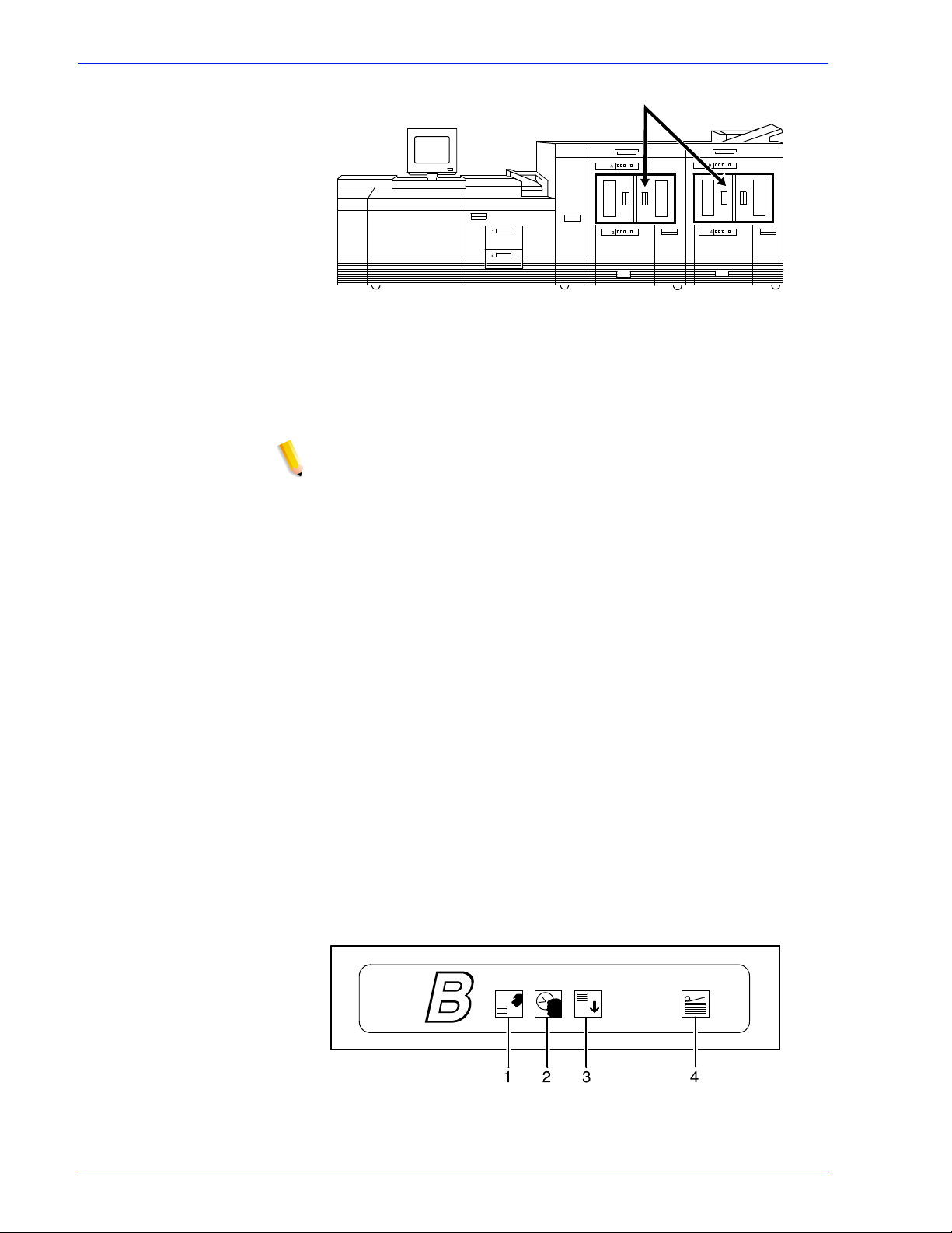
Figure 1-3 Submission and print order of jobs in a queue
1. Queue overrides
2. Exception pages
3. Job ticket
4. Submission print protocol (lp, lpr, nprint)
5. Set page device values/PCL copy count
6. Queue defaults
You can make changes to the printing attributes of a PostScript,
PCL, TIFF, ASCII, and PDF job (that is, a non-LCDS job), as long
as the job is not streaming. This includes changing the type of
paper on which it is printed or specifying printing order from last
page to first (N to 1).
Printer overview
The printer receives data from the controller and prints the
document according to the print options s pecified by the us er. The
printer also st acks the pr in ted output , co llat es i t, and, i f conf igured
with one of the available optional third-p arty finishing devices,
performs finishing functions such as binding, stitching, or
perforating.
The Xerox DocuPrint 100/115/135/155/180 EPS printer is a
monochrome printer. If it receives print jobs that contain color
commands, it prints them in black or shades of gray.
Throughput speeds The Xerox DocuPrint 100/115/135/155/180 EPS prints LCDS data
from a mainframe host computer, emulating an IBM 4245 or 3211
line printer. The printing system can receive data over a channel
through bus and tag cables and throug h the Socket Gateway or lpr
using TCP/IP.
1-8 Operator Guide
Page 25

Table 1-3 Throughput speeds
Overview
Monthly print
volume
Printing system
DP100 EPS 100 ppm 100 ppm
DP115 EPS 115 ppm 115 ppm
DP135 EPS 135 ppm 154 ppm
DP155 EPS 155 ppm 155 ppm
DP180 EPS 180 ppm 206 ppm
Maximum
throughput
Maximum throughput
with 7 by 10 in / 178 by
254 mm paper
NOTE: Pages per minute refers to sides of a printed sheet
(actually impressions per minute).
Using the smaller papers, such as 7 by 10 inch / 178 by 254 mm
or B5, the printer can print at maximum speed. To print these
sizes, the printer requires the optional small paper kit.
The monthly print volume for the Xerox Docu Print Enterprise
Printing Systems is up to 6 million impressions.
Table 1-4 Minimum and Maximum monthly print volume
Printing system Minimum Maximum
DP100 EPS 800 thousand 3 million
DP115 EPS 1 million 3.5 million
DP135 EPS 1.2 million 4 million
DP155 EPS 1.4 million 4.5 million
DP180 EPS 1.8 million 6 million
Roll feeder support The roll feeder option may be installed in the inverter feeder/
stacker module, replacing the feeder tray. This option does not
require DFA software or any additional hardware. The maximum
number of feeder/stacker modul es supported for this configuration
is four, including the inverter module with the roll feeder . With the
two processor feeder trays, this mak e s a total of six input trays
possible.
Jam recovery The printer engine monitors the print job so that, if a paper jam
occurs, the job resumes on the correct page, at the correct tab,
using the same color paper, and so forth, providing complete
document integrity.
Operator Guide 1- 9
Page 26

Overview
Printer components
The components and special f eatures of the Xerox DocuPrint 100/
115/135/155/180 EPS printer are shown in the follo wing figure.
Figure 1-4 Printer components
1. Processor feeder trays
2. Sample tray
3. Attention light
4. Purge tray
5. Feeder/stacker module
6. Inverter feeder/stacker
NOTE: Some printer configurations may include a control console
(not shown).
Processor Feeder Trays
Two pro cessor feeder trays (tray s 1 and 2) are located in the main
part of the printer and are not part of a feeder/stacker module.
Trays 1 and 2 can handle paper sized from 8 by 1 0 inches / 203 by
254 mm to 9.02 by 14.02 inches / 230 by 356 mm.
Sample tray
The sample tray, located on top of the printer, receives output
such as transparencies, sample sheets from printing jobs, prints
from system files such as forms, and wast e sheets that cannot be
sent to the purge tray.
Monitor the sample tray and empty it when it contains 100 sheets.
NOTE: The system does not notify you when the tray is full.
1-10 Operator Guide
Page 27

Attention light
An Attention light is mounted on top of the inverter module. Thi s
light either blinks or modulates (alter nately brightens and dims)
when the printer requires operator attention. The light has three
states:
• Off: No printer problems exist that requir e a ttention.
• Steady light: A sit uation exists that needs attention soon .
• Flashing: The printer has st opped and requires your attention
immediately.
NOTE: When the Attention light starts flashing, an explanatory
message appears in the Console wi ndow on the controller screen.
Purge tray
The purge tray is loc ated on top of the l ast f eeder/ st ack er module.
Aborted sheets (for example, damaged sheets or sheets cleared
after a paper jam) are sent to thi s tray. The purge tray should be
emptied when it has received 100 sheets of p aper.
Overview
NOTE: The system does not notify you when the tray is full.
Feeder trays
Multiple feeder trays can be configured to feed paper for jobs in
the most effective manner. For example, the trays can provide
nonstop printing of a complex job that requires many paper
stocks, or only a few stocks, by usi ng the trays conti nuous loading
capability. A different input tr ay can also be select ed for each cop y
of a specific page in a print job, for example, to provide different
paper colors for specific pages.
The printing system may have up to six feeder trays: two
processor feeder trays and two to four high-capacity trays. Four
addressable input trays are standard with the system, and two
additional high-capacity trays are optional.
Feeder tray capacity The feeder trays have the following capaciti es, based on 20 pound
or 80 gsm (grams per square meter) paper:
• Tray 1: 1100 sheets
• Tray 2: 600 sheets
• Trays 3, 4, 5, and 6 (high-capacity trays): 2600 sheets each
An elevator moves each tray up or down when it is i n use. In each
tray, a control panel consisting of a button, indicators, and paper
level displays controls the elevator tray and indicates its status.
Operator Guide 1- 11
Page 28

Overview
Figure 1-5 Feeder tray control panel
1. Ready to Open indicator on feeder trays
2. Please Wait indicator on feeder trays
3. Tray Unlock button (feeder)
4. Paper Level indicators on feeder trays
Ready to Open
indicator on
feeder trays
Please Wait
indicator on
feeder trays
Tray Unlock button
(feeder)
Paper Level
indicators on
feeder trays
Glows green when the tray can be pulled out and paper can be
added to it.
Shows that the tray is in motion. This indicator is lit red when the
Tray Unlock button i s pressed, while the tray is lowering, and while
the tray is rising. The indicator goes off when the tray elevator
reaches its destination.
Enables the feeder tray to be opened.
• If the tray is in use when this button is pressed, the feed
selection switches to the backup tray if one has been
identified. Otherwise, pri n ting stops.
• If the tray is in use and selected as a bac kup tray, pressing the
Tray Unlock button causes the tray elevator to lower and the
tray to be unavailable for auto switching.
• If the tray elevator is in the raised posit ion and the tray is not in
use or selected as a backup tray, pressing this button causes
the elevator to lower with no effect on printing operations.
This button functions when the Please Wait indicator is off.
Display the approximate quantity of p aper in the tray. Each display
shows paper by quarter reams up to one ream, and then by full
reams. The green indicator appears above it s Paper Level
indicator.
Stacker bins
Each output stacker bin has offsetting capability and a capacity of
2500 sheets of 20 pound or 80 gsm paper.
NOTE: This capacity does not apply to 11 by 17 inch and A3
papers. Because of the additional weight these large sheets add
to the bins, each bin is restricted to hold onl y up to 1500 sheet s of
A3 or 11 by 17 inch papers, for safety reasons.
1-12 Operator Guide
Page 29
Overview
Figure 1-6 High capacity stackers (HCS)
The stackers can stack the pri nted output in the bin three ways:
• Directly onto the bin platf orm.
• Into a container that is set on top of the bin platform.
NOTE: The stacking capacity is approximately 100 to 150
sheets less when stacking into a container.
• Onto a pallet without a container (for paper sizes 11 by 17
inches or A3 only).
Using the Stacking windows on the user interface, you can select
the level to which paper will be stacked in the HCS.
A stacking elevator maintains the paper at the proper level for
stacking and lower s the stack for unloading. An offset mechanism
offsets print ed sets toward the front or back of the HCS bin.
Bin control panels
on stackers
The elevator platform lowers under the following conditions:
• The bin capacity has been reached.
• A selection to lower the platform is entered at the printer
control console or a user interface window.
• The job being printed reaches a designated unload boundary.
Each HCS bin has unlinked double doors to give you easy and
safe access for unloading output from the printer.
The elevator bin platform automatically rises when the doors are
closed after the stacker has been unloaded.
Each stacker bin has a control panel consisting of buttons and
indicators.
Figure 1-7 High capacity stacker bin control panel
1. Ready to Unload indicator on stacker bins
Operator Guide 1- 13
Page 30

Overview
2. Please Wait indicator on stacker bins
3. Bin Unload button on stacker
4. In Use indicator on stacker bin
Ready to Unload
indicator on
stacker bins
Please Wait
indicator on
stacker bins
Bin Unload button
on stacker
In Use indicator on
stacker bin
When this indicator glows, you can remove printed sheets from
the stacker bin.
When this indicator glows, the elevator is in motion. This indicator
turns off when the platform reaches its destination.
Lowers the bin elevator.
• If the bin is in use when this button is pressed, the printed
pages begin stacking i n the oth er stacker bin, if auto swit ching
has been enabled.
• If the bin is not in use, pressing this button does not affect
printing operations.
When this indicator glows, the bin has been made ready to receive
output.
Feeder/stacker modules
The feeder/stacker modules cont ain the high-cap acity feeder trays
and the stacker bins. The printer may have up to four feeder/
stacker modules (including t he inverter f eeder/stac ker), cont aining
feeder trays 3, 4, 5, and 6, and stacker bins A, B, C, and D. Each
module contains one high-capacit y feeder tray and one high
capacity stacker bin.
High-capacity
feeders
High-capacity
stackers
Inverter The inverter is part of the i nverter feeder/s tacker module. It allows
The high-capacity feeder (HCF) trays are located in the bottom
half of the feeder/stacker modules. Each HCF tray can hold up to
2500 sheets of 20 pound or 80 gsm paper.
The high-capacity feeder trays can handl e paper sized from 8 by
10 inches / 203 by 254 mm to 17 by 14.02 inches / 432 by 356
mm.
Unlike the processor feeder trays, the HCF trays have Paper
Level switches, which detect the posit ion of the elevator to
determine the fullness of the tray.
The high-capacity st acker (HCS) bins are loc ated in the top half of
the feeder/stacker modules, accessed through double doors.
Two high-capacity stacker bins are standard, with up to two
additional bins available as options (providing up to four bins
total). Each bin holds up to 2500 sheet s of 20 pound or 80 gsm
paper.
for proper collation of the print job. It also directs printed output to
the sample tray, when required.
1-14 Operator Guide
Page 31
Printer control console (not shown)
Where available, the printer control console is the color monitor
located on top of the printer. It keeps you informed of the printer
status, and enables you to control certain functions of the printer,
such as stopping printing and continuing an interrupted job,
without returning to the contr oller .
Printer configurations
The standard printer configuration consists of an inverter feeder /
stacker plus one additional feeder/stacker. Some configurations
may include a printer control console (not shown).
Overview
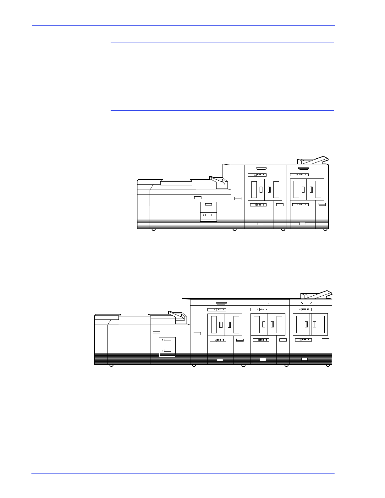
Figure 1-8 Printer with inverter feeder/stacker + feeder/stacker
(standard base configuration)
In addition, the printer is avail able with three or four f eeder/stack er
modules.
Figure 1-9 Printer with inverter feeder/stacker + feeder/stacker +
feeder/stacker
Operator Guide 1- 15
Page 32

Overview
Figure 1-10 Printer with inverter feeder/stacker + feeder/stacker +
feeder/stacker + feeder/stacker
NOTE: The bypass transport device is not available for this
configuration (four feeder/stacker modules).
Printer options
Function of the
bypass transport
The printing system is avail able in several confi gurations, and may
be connected to a bypass transport.
Bypass tr ansport
The bypass transport optio n enables third-party finishing devices
to interface directly with t he pr inti ng system. The bypass transport
allows you to customize your printer for increased efficiency and
specialized applications i n volving finishing.
NOTE: A bypass transport must be installed for the printing
system to support a third-pa rty finishing device.
Connected to the last feeder/st acker module, the bypass transport
moves paper from the stacker to a third-party finisher such as a
stitcher, booklet maker, tape binder, and so on. By making
selections on the display monitor, you can program the printer to
send output to the bypass transport, which feeds the output to the
finishing equipment.
1-16 Operator Guide
Page 33

Overview
Figure 1-11 Printer with inverter feeder/stacker + feeder/stacker +
bypass transport
Figure 1-12 Printer with inverter feeder/stacker + feeder/stacker +
feeder/stacker + bypass transport
The illustrations above show a printer with two feeder/stacker
modules and a bypass transport, and a printer with three feeder/
stacker modules and a bypass transport. With the bypass
transport installed, the printer can support up to three feeder/
stacker modules, includi ng the inverter feeder/stacker.
Paper stocks
supported on
The bypass transport a ccepts all paper stocks on which the prin ter
can print, and it accommodates simplex and duplex printing.
bypass transport
DFA suppor t The bypass transport meets the Xerox Document Feeding and
Finishing Architecture (DFA) specifications. The system software
supports DFA. However, in order for the bypass transport to
function correctly, you need to set up finishing personality profiles
to identify your finishing device to the printing system. (The
customer support represent ative for your finishing devi ce can give
you the information you need to create a personality profile for
your third-party finishing device. )
Support and interface with feeders
For information on marketing partners that provide solutions for
support and interface with feeders, contact your local Xerox sales
representative.
Operator Guide 1- 17
Page 34

Overview
The input enablement device is NOT an option on the Xerox
DocuPrint 155 and 180 EPS.
NOTE: The input enablement device is available only for the
Xerox DocuPrint 100, 115, and 135 EPS.
7 by 10 inch enablement kit
The 7 by 10 inch enablement kit all ows the print ing system to pr int
on 7 by 10 inch/178 by 254 mm paper siz e, with thro ughput speed
of up to 206 PPM.
Paper paths
The paper path is the route that materials (paper, transparencies,
labels, and so on) follow through the printer f rom the feeder trays
to the output bins or finisher.
Printer paper path
The following figure shows the path the paper takes through the
printer.
1-18 Operator Guide
Page 35

Overview
Figure 1-13 Route of paper through the printer
1. Processor feeder tray 1
2. Processor feeder tray 2
3. High-capacity feeder tray 3
a. Side 1 of sheet leaving feeder tray
b. Drilled holes (on right edge)
c. Origin 0,0: portrait orientation
4. High-capacity feeder tray 4
a. Side 1 of sheet leaving feeder tray
b. Drilled holes (on right edge)
c. Origin 0,0: portrait orientation
5. Inverter
6. Duplex inverter
7. Sample tray
8. Disk inversion
9. High-capacity stacker bin A
a. Side 2 of sheet stacked in bin
b. Drilled holes (on left edge)
c. Origin 0,0: portrait orientation
10. High-capacity stacker bin B
a. Side 2 of sheet stacked in bin
b. Drilled holes (on left edge)
c. Origin 0,0: portrait orientation
Operator Guide 1- 19
Page 36
Overview
11. Purge tray
12. Bypass transport
a. Side 2 of sheet passing through bypass transport
b. Drilled holes (on left edge)
c. Origin 0,0: portrait orientation
Bypass transport paper path
The following figure shows the paper path through the bypass
transport, viewed from the front of the printer.
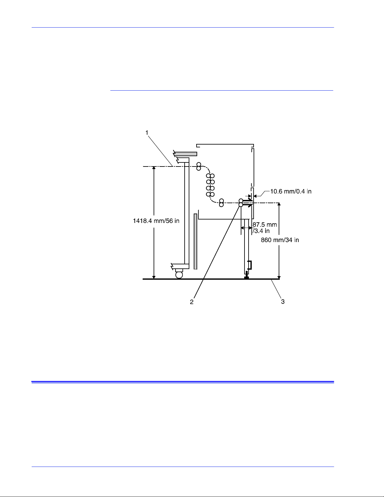
Figure 1-14 Bypass transport paper path
1. Sheet path
2. Exit rollers
3. Floor
Controller overview
The controller receives LCDS, PostScript, and PCL data streams
from a mainframe host or a works tati on client, pr ocesses t he data,
and sends it to the printer. The controller also provides the printer
with print data and commands and receives status information
from the printer.
The controller consists of a Sun Workstation computer, which is
run by the Sun Solaris Operating environment. Also resident on
the controller is the Document Services Platform application
1-20 Operator Guide
Page 37

Overview
software, known as DocuSP sof twa re, which manages al l printi ng,
diagnostic, and administrative functions on the printing system.
The DocuSP software includes a full-c olor graphical user
interface, which enables you to interact wi th the printi ng system to
set up and configure the system, to set up and implement system
options, to run print jobs, etc.
Online Help (menus and buttons) provides access to online help
that contains information wh en request ed.
Accessing DocuSP
remotely (Re mote
Workflow)
Controller components
Remote Workflow, a remote graphical user interface (GUI), is
available for installation from a CD. Remote Workflow allows you
to manage your DocuSP-based printers from a single PC or Sun
workstation. You may set your preferences from the remote client
to disable or enable some or all connections.
Remote Workflow allows you to configure the printers that you
want to manage, and provides real time status of the printers. You
may switch between the printers that you are managing, but you
can display only one printer GUI at a time.
The remote client GUI looks and functions the same as the local
DocuSP GUI on the controller.
The controller consists of a specially-configured Sun workstation
and uses proprietary Xerox hardware, firmware, and software.
Your controller has one of two possible configurations, described
in the following sections.
NOTE: Controller hardware configurations are subject to change,
to keep up with technology advances.
Sun workstation
The controller is based on either the Sun Blade 1000/2000, Sun
Blade 2500 or the Sun W1100z workstations with highperformance architecture for complex processing tasks.
Operator Guide 1- 21
Page 38
Overview
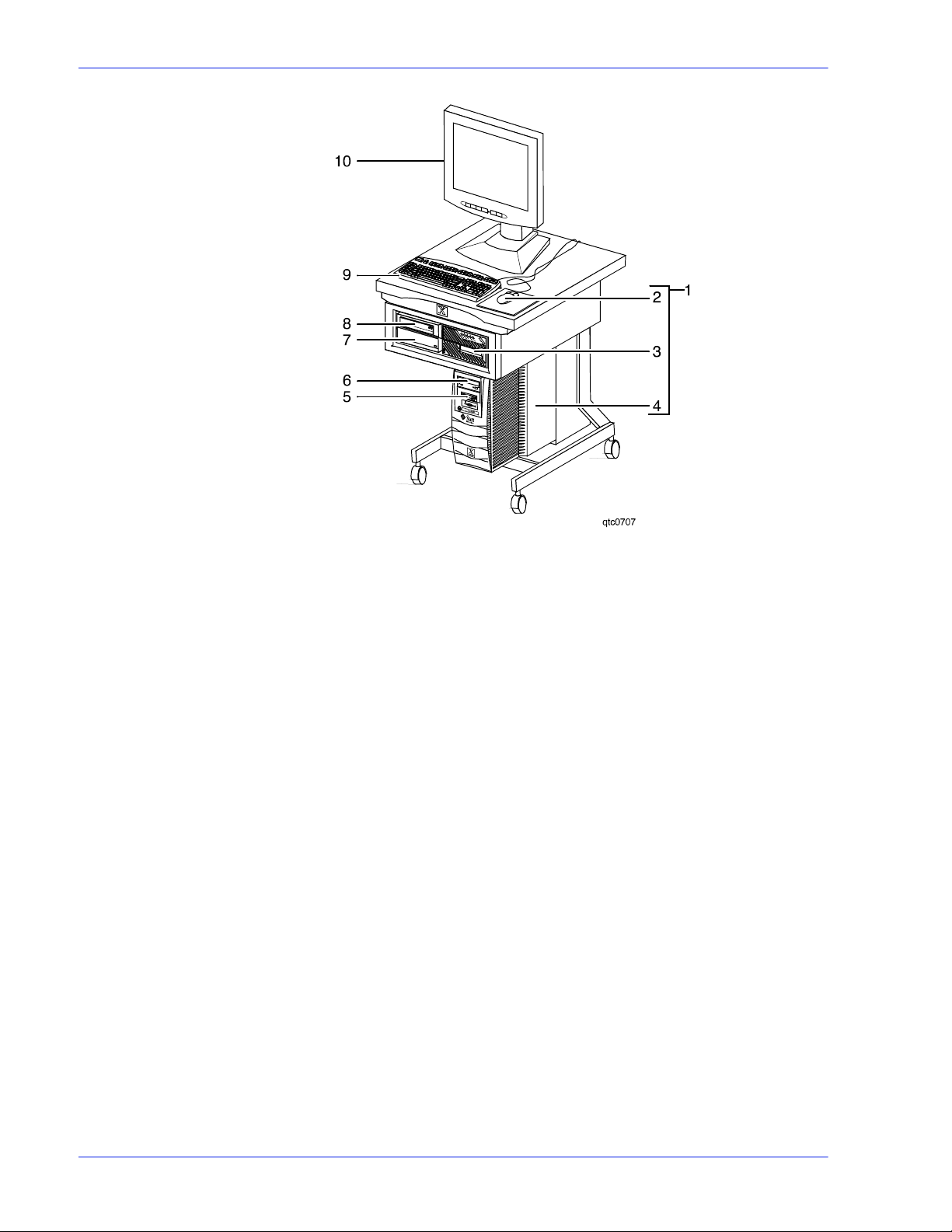
Figure 1-15 Sun Blade 1000/2000
1. Controller stand
2. Mouse
3. 18/36-track cartridge tape drive (optional)
4. Processor
5. Diskette drive
6. CD drive
7. Quarter-inch cartridge (QIC) tape drive
8. External fixed disk drive (optional)
9. Keyboard
10. Display monitor
1-22 Operator Guide
Page 39

Overview
Figure 1-16 Sun Blade 2500 or Sun W1100z controller
1. Display monitor
2. External diskette drive
3. Keyboard
4. Mouse
5. External fixed disk drive (optional)
6. Quarter-inch cartridge (QIC) tape drive
7. Processor
8. DVD/CD-RW drive
9. 18/36-track cartridge tape drive (optional)
10. Controller stand
Operator Guide 1- 23
Page 40

Overview
The Sun workstation controller may contain the following
hardware components:
• Processor (system unit) containing the following:
– One or two UltraSPARC high-speed processing unit (CPU)
modules
– One or two 1-GB memory modules
Note: In Xerox Europe, all printers use a 2 GB memory
configuration.
– Hard disk drive
– CD or DVD/CD-RW drive
– Diskette drive (Sun Blade 1000/2000 only)
– Ethernet
– One or two Printer Controller Interf ace (PCI) boards to
interface with the printer
– Video graphics board
– Universal Serial Bus (USB) keyboard and three-button
mouse
– 17-inch flat panel monitor
– External diskette drive (Sun Blade 2500 only )
Processor The central processing unit may contai n the memory, internal disk
drive, a graphics board, a DVD-ROM drive, a diskette drive, power
receptacle and outlet, connect o rs, and ports.
• Memory: One or two 1-GB Dual In-line Memory Modules, or
DIMMs, are provided as a standard feature of the processor .
• Hard disk drive: The internal hard disk drive stores the
operating system software, the NPS/IPS Extension
application, and any queued print jobs are stored on the
internal disk. This disk cannot be used to store other
applications or data except as directed by your service
representative.
• Diskette drive: Diskettes are used to install fonts and to load
files to, and back up files from, the internal disk drive. The
diskette drive uses industry standard 3.5 inch, 1.44 MB,
double-sided, high-density diskettes.
NOTE: The diskette drive is external, and plugs into the
processor back panel.
• DVD-ROM drive: The DVD-ROM drive is a high density, readonly , optical las er storage device used for l oading the NPS/IPS
operating system and other files. The DVD-ROM drive is
located in the processor above the diskett e drive.
1-24 Operator Guide
Page 41

Figure 1-17 Drive locations on Sun Blade 1000/2000
1. CD drive
2. Diskette drive
Overview
Figure 1-18 DVD/CD-RW drive location on the Sun Blade 2500 or or
Sun W1100z
• Back panel: The back panel of the processor has a power
receptacle and outlet, connectors, connector openings, ports,
fan, and vent.
Keyboard The keyboard consists of alphanumeric ke ys similar to a
typewriter, symbols and special character keys, an extended
character set, and function keys. The keyboard is one of your
main methods of communicating with the printer. You can use the
keyboard to make selections, and to enter commands that control
Operator Guide 1- 25
Page 42

Overview
functions such as requesting sample prints, or shutting down the
system.
Mouse The mouse is another main method of communicating with the
printer.
Display monitor The LCD monitor allows you to interact with the printer and to
monitor its int eraction with the various components. During a print
job, printer error messages may display to notify you of any
unexpected conditions.
Optional processor
components
The controller may be configured with any of the followi ng optional
components:
• Connectivity board to enable Token Ring
• Channel interface board for channel connection to a host for
online LCDS printing
• One SCSI board to connect to an external tape drive
• Creator-3D series 3 graphics board (may repla ce the vi deo
graphics board delivered with the controller)
External components and options
The following components are external to the processor. The
controller stand cont ains sections that may hold these
components.
• Quarter-inch cartridge (QIC) tape drive
• 36-track cartridge tape drive (optional)
• External 36 GB hard disk drive (optional)
NOTE: This additional drive is standard equipment on systems
with the NPS/IPS extension.
Controller stand
The controller is provided with a specia l stand that holds all its
standard components. In addi tion to the processor, keyboard with
the mouse, and the quarter-inch cartridge tape drive, the stand
can accommodate the optional 36-track tape drive and one
external hard disk drive (required for the NPS/IPS Extension
option).
Online and offline interfaces
The Xerox DocuPrint 100/115/135/155/180 EPS may be
configured for either the online interface, the offline interface, or
both.
Online interface The online (channel-attached) interface receives input directly
from any environment that supports the IBM 3211 and 4245 host
systems.
1-26 Operator Guide
Page 43
Overview
Offline interface The Xerox DocuPrint 100/115/135/155/180 EPS supports three
types of peripheral devices from which you can import resource
files such as forms, fonts, and JSLs, and receive print data from
tape. These devices are called “peripheral” because they handle
media external to the system disk.
The following drives are supported:
• 26-track cartridge tape drive (QIC)
• 9-track reel tape drives
• 36-track cartridge tape drives
Moving the controller
To ensure consistent performance and avoid any damage to
equipment, follow these rules for placi ng the components of the
workstation controller:
• Use the controller stand that comes with your printing system
equipment.
• Keep the processor in an upright, vertical position as
illustrated below.
• Allow at least 6 inches / 152 mm of unobstructed space at the
front and rear of the processor, so the fan and vents are not
blocked.
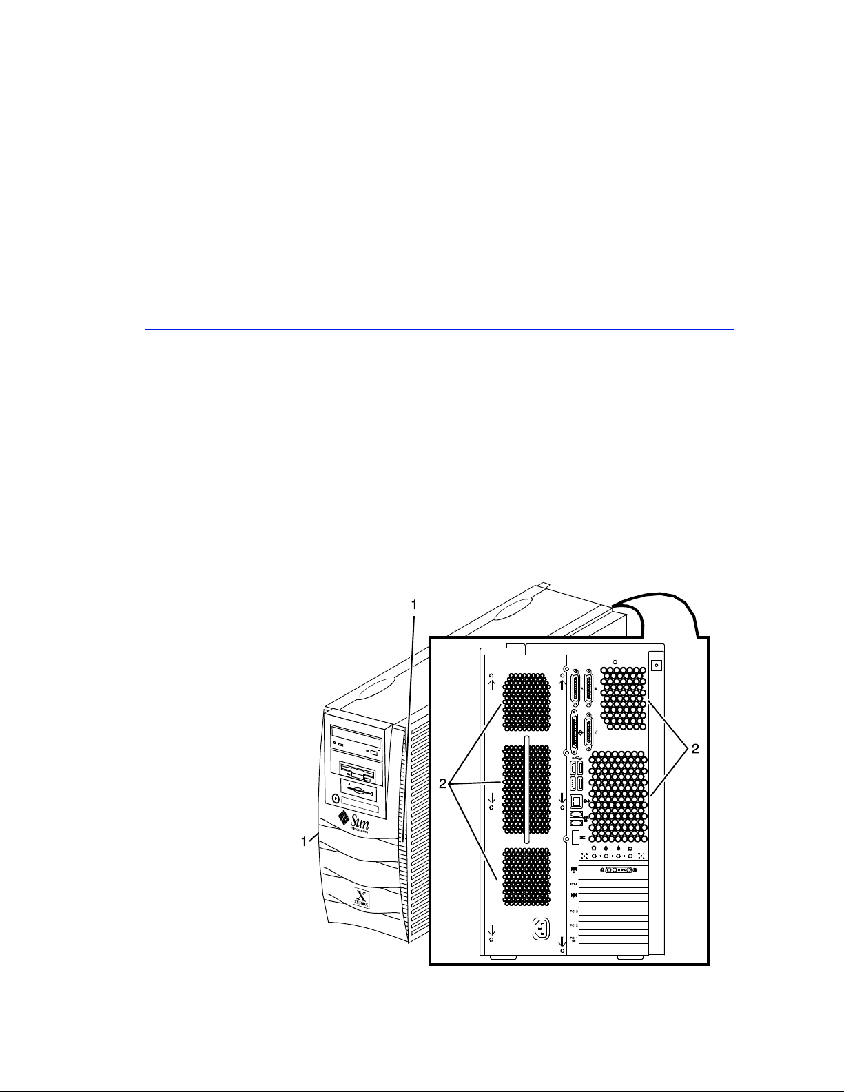
Figure 1-19 Sun Blade 1000/2000 fan/vent locations to keep clear
Operator Guide 1- 27
Page 44

Overview
1. Vents in front of processor
2. Vents in back of processor
Figure 1-20 Sun Blade 2500 and Sun W1100z common fan and vent
locations to keep clear
1. Vents in front of processor
2. Vents in back of processor
CAUTION: Do not place the monitor on top of the processor. Do
not block any fan or vent on the front, sides, or rear of the
processor.
Do not:
• Do not place the monitor and processor on a desk or table top.
• Do not place the monitor on top of the processor.
• Do not allow any piece of equipment to blow warm air into the
air intake vents of the pr ocessor.
• Do not place the processor on its side, or i n any other posit ion
but the upright, vertical position achieved by using the
controller stand.
• Do not place the processor or monitor on top of the printer.
1-28 Operator Guide
Page 45

Tape drives overview
Overview
The DocuPrint 100/115/135/155/180 EPS supports several types
of tape drives that may be used to load resources (forms, fonts,
etc.) or to submit offline LCDS print jobs.
The 26-track cartridge tape drive, provided with your Xerox
DocuPrint 100/115/135/155/180 EPS, can be used only to import
resources to the system disk. 9-t rack and 36-tr ack t ape drives can
be used to submit print jobs to the DocuPrint EPS, or load
resources.
The DocuSP Tape Client software enables transmission of data
from a cartridge or open reel t ape to the DocuPrint EPS controller
via the Socket gateway.
26-track cartridge
tape drive (QIC) (for
resource loading
only)
The 4 GB external SCSI quarter inch cartridge (QIC) tape drive is
an external device provided with the Xerox DocuPri nt 100/115/
135/155/180 EPS. The cartridge tape drive connects to the
controller through the SCSI port on the processor back panel.
Like the diskette and DVD drives, this tape drive is not an input
source for print jobs or for any other data or application. You can
use it to load resource files, and the service representative uses it
to load system maintenance files or to save diagnostic
information.
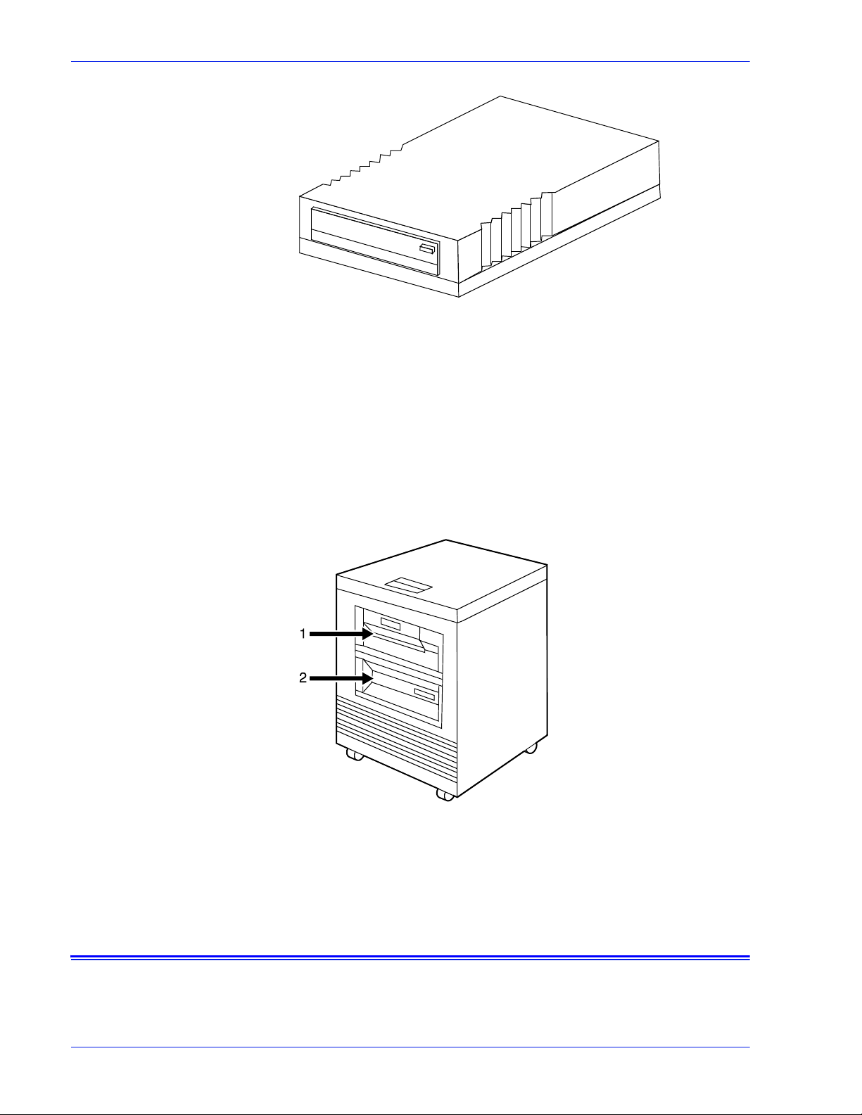
Figure 1-21 26-track cartridge tape drive (QIC)
36-track cartridge
tape drive
Operator Guide 1- 29
An 18/36-track cartridge tape drive is an option. You can use this
drive to load resources and to submit offline LCDS print jobs.
Page 46
Overview
Figure 1-22 18/36-track cartridge tape drive
Peripheral cabinet
(9-track and 18/36-
track tape drives)
Some Xerox customers may already have a peripheral cabinet
that houses a 9-track magnetic and an 18/36-track cartr idge tape
drive. The DP EPS supports existing peripheral cabinet s, but they
are not available with new systems. In addition, if a peripheral
cabinet has either of the following 18-track tape drives, they are
not supported:
• STK 4220 MOD 1 tape drive
• STK 4220 MOD 2 tape drive
Figure 1-23 Peripheral cabinet
1. 9-track magnetic tape drive
2. 18/36-track cartridge tape drive
Paper sizing and print speed
The printer paper trays have edge gui de sensors that det ect paper
length and width. The system select s correct paper trays for the
print job based on the paper size speci fied in the job, as follows:
1-30 Operator Guide
Page 47

• If an exact match is found, the print job continues.
• If an exact match is not found, the programmer can specify in
the job for the printer to do one of the following:
– Stop pri nting the job and print an error sheet.
– Print the data on an oversized sheet.
If you encounter any problems related to pa per sizing, contact
your lead operator or Xerox service rep resentative.
Long and short edge feeding
To feed through the printer, the leadi ng edge of the p aper must be
at least 10 inches long. Therefore, the following standard sizes of
paper must be loaded so that sheets feed long edge first:
• 7 by 10 inch
•B5
•A4
Overview
• US Letter
•B4
• US Legal
The following papers, which have long edges greater than 14.33
inches / 364 mm must feed short edge first:
•A3
• US Ledger or US Tabloid
NOTE: JIS B4 can be fed either long edge or short edge first.
Paper width and throughput speed (LCDS printing only)
The width of the paper you use for your LCDS print job is directly
related to the rate at which the printer can print the job. The rate at
which a job prints is called the “thr oughput speed” and is
measured in pages per minute (ppm).
NOTE: “Pages per minute” actually means “impressions per
minute,” referring to one side of a printed sheet.
A pitch is the amount of time the printer takes to image a page on
the photoreceptor belt. The term “pi tch mode” refers to the number
of pitches that can occur during one complete photoreceptor
revolution. The pitch mode in which a specific job prints is based
on the paper size used for that job.
The following table lists the pitch mode boundary values, paper
widths, and related printing speeds for the system. The chart
Operator Guide 1- 31
Page 48

Overview
shows that the shorter the paper width, the higher the pitch mode
and the faster the throughput speed (hi gher p age per mi nute rat e).
Table 1-5 Throughput data for DP100
Pitch Paper width Speed
5 7 to 12.12 in / 178 to 308 mm 100 ppm
4 12.12 to 15.31 in / 308 to 389 mm77 ppm
3 15.31 to 17 in / 389 to 432 mm 58 ppm
Table 1-6 Throughput data for DP115
Pitch Paper width Speed
6 7 to 10.19 in / 178 to 259 mm 116 ppm
5 10.19 to 12.12 in / 259 to 308 mm96 ppm
4 12.12 to 15.31 in / 308 to 389 mm77 ppm
3 15.31 to 17 in / 389 to 432 mm 58 ppm
Table 1-7 Throughput data for 135
Pitch Paper width Speed
8 7 to 7.4 in / 178 to 188 mm 154 ppm
7 7.4 to 9.01 in / 188 to 229 mm 135 ppm
6 9.01 to 10.19 in / 229 to 259 mm116 ppm
5 10.19 to 12.12 in / 259 to 308 mm96 ppm
4 12.12 to 15.31 in / 308 to 389 mm77 ppm
3 15.31 to 17 in / 389 to 432 mm 58 ppm
Table 1-8 Throughput data for 155
Pitch Paper width Speed
6 7 to 10.19 in / 178 to 259 mm 154 ppm
5 10.19 to 12.12 in / 259 to 308 mm128 ppm
4 12.12 to 15.31 in / 308 to 389 mm103 ppm
3 15.31 to 17 in / 389 to 432 mm 77 ppm
1-32 Operator Guide
Page 49

Overview
Table 1-9 Throughput data for DP180
Pitch Paper width Speed
8 7 to 7.4 in / 178 to 188 mm 206 ppm
7 7.4 to 9.01 in / 188 to 229 mm 180 ppm
6 9.01 to 10.19 in / 229 to 259 mm154 ppm
5 10.19 to 12.12 in / 259 to 308 mm128 ppm
4 12.12 to 15.31 in / 308 to 389 mm103 ppm
3 15.31 to 17 in / 389 to 432 mm 77 ppm
Each time a job requires a different paper size that changes
across a pitch boundary, the system performs a time-consuming
xerographic quality adjustment. When the printing speed of an
LCDS job appears to degrade due to the use of mixed stock s izes,
the following actions may improve the performance:
• You can optimize throughput by double clicking on a job in Job
Manager or double clicking on a queue in Queue Manager and
selecting Properties. The Output tab has a Mixed Stock Size
Job window where you can select Optimize throughput. You
must also enter the width of the widest paper in inches or
millimeters for the job.
• The job programmer may be able to improve the speed by
using the LCDS PDL command OUTPUT TMODE in the JSL
to run the print job in a lower pitch mode. Refer to the
OUTPUT TMODE parameter in the Xerox Document Servic es
Platform Using LCDS Print Description Langua ge for
information on using this command.
• Similarly, if the system cycles down frequently because your
external finishing equip ment has a sl ower throughput r ate than
the printing system, the OUTPUT TMODE command can be
used to lower the pitch mode to match the speed of the
finishing equipment. This can improve overall throughput by
avoiding time-consuming cycle downs.
NOTE: Pitch mode changes are supported only for LCDS printing.
Paper size and pitch mode minimum and maximum
The illustrations in this section show the pi tch modes i n whic h you
can operate, with the smallest and largest size p apers supported
by the printing system.
Operator Guide 1- 33
Page 50

Overview
Using small paper
sizes in 8 pitch
mode
Printing in 8 pitch mode provides the highest throughput speed
available (up to 206 ppm). However, keep the following in mind
when you select the paper you want to use for this mode:
• Paper sizes smaller than 8 inches / 203 mm in width are
supported only when the optional 7 inch paper kit is installed
on the printer.
• The leading edge of any paper used in the printer cannot be
less than 10 inches / 254 mm long.
The following figure illustrates the maximum and minimum paper
sizes supported in 8 pitch mode.
Using large paper
sizes in 3 pitch
mode
Figure 1-24 8 pitch mode paper sizes
1. Maximum paper size for 8 pitch mode
2. Minimum paper size for 8 pitch mode
3. Travel direction of sheets out of paper tray
Large paper sizes with widths of 15.31 to 17 inches / 389 to 432
mm are supported only in 3 pitch mode and must feed short edge
first. These paper sizes slow down the throughput speed.
Therefore, a short edge feed job takes longer to print than a long
edge feed job.
NOTE: The system can support 14 by 17 inch / 356 by 432 mm,
20 pound or 80 gsm paper stock in 3 pitch mode. However,
printing performance is not guaranteed for all ty pes of paper of this
size. Heavy (110 pound / 200 gsm) and light (16 pound / 60 gsm)
weight papers can cause jams thr oughout the s ystem, and ar e not
recommended.
The following figure illustrates the maximum and minimum paper
sizes supported in 3 pitch mode.
1-34 Operator Guide
Page 51
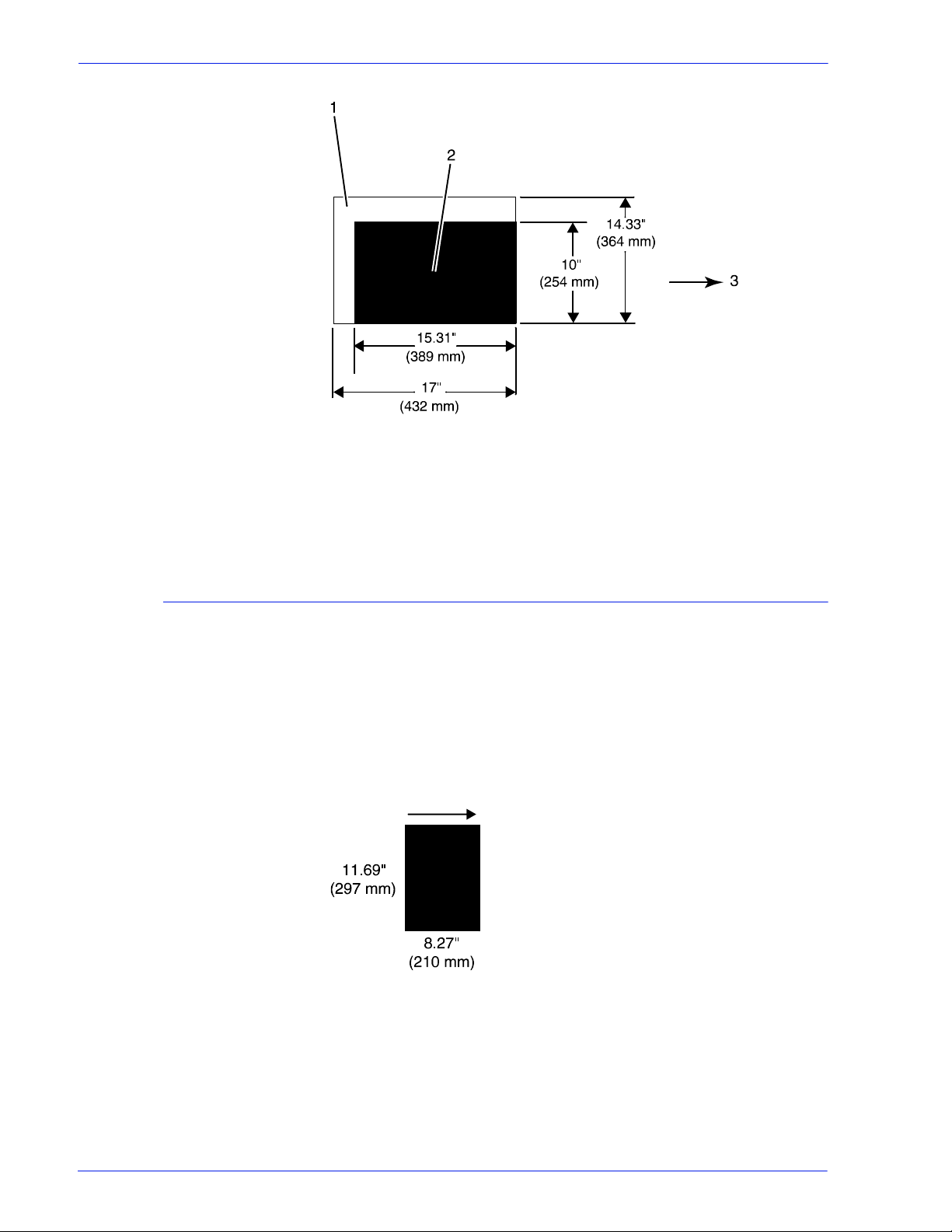
Figure 1-25 3 pitch mode paper sizes
1. Maximum paper size for 3 pitch mode
2. Minimum paper size for 3 pitch mode
3. Travel direction of sheets out of paper tray
Overview
Feed direction for standard paper sizes
Currently, 14.33 inches / 364 mm is the maximum paper length for
which the system supports long edge feeding (5 to 8 pitch mode).
Any papers with long edges greater than this (such as 11 by 17
inch / 279 by 432 mm paper) must be loaded for short edge
feeding (3 or 4 pitch mode).
The following figures show how some of the standard paper sizes
feed through the printer in various pitch modes.
European papers
Figure 1-26 A4 (210 by 297 mm) paper feeding (long edge feed)
Operator Guide 1- 35
Page 52

Overview
Figure 1-27 A3 (297 by 420 mm) paper feeding (short edge feed)
US papers
Figure 1-28 US Letter (8.5 by 11 inch) paper feeding
(long edge feed)
Figure 1-29 US Ledger or US Tabloid (11 by 17 inch) paper fe eding
(short edge feed)
B4 papers There are two versions of B4 paper: European (ISO B4: 9.84 by
13.89 inches / 250 by 353 mm) and Japanese (JIS B4: 14.33 by
10.12 inches / 364 by 257 mm). European B4 feeds long edge
first, while JIS B4 may feed either long edge or short edge first.
1-36 Operator Guide
Page 53

Overview
Figure 1-30 B4 (250 by 353 mm) paper feeding (long edge feed)
Figure 1-31 JIS B4 (257 by 364 mm) paper feeding
(may be long or short edge feed)
Operator Guide 1- 37
Page 54

Overview
1-38 Operator Guide
Page 55

2 Managing the printer
Controlling the printer
This chapter describes the operator tasks that are related to
printing and print quality.
You can perform the following tasks o n the DocuSP Pri nt Serv ices
window.
You can also select them from the Options pull-down menu on the
Printer Manager window.
NOTE: Where available, the printer control console enables you
to control certain functions of the pri nter, such as stopping printing
and continuing an interrupted job, without returning to the
controller.
Interrupting printing
Click the red [Pause Printing] icon.
Resuming printing
Click the green [Resume Printing] icon.
Powering on the printer
Select [Printer On] from the Printe r menu.
Powering off the printer
1. Select [Printer Off] from the Printer menu.
2. Click [Yes] on the confirmation window.
Operator Guide 2-1
Page 56
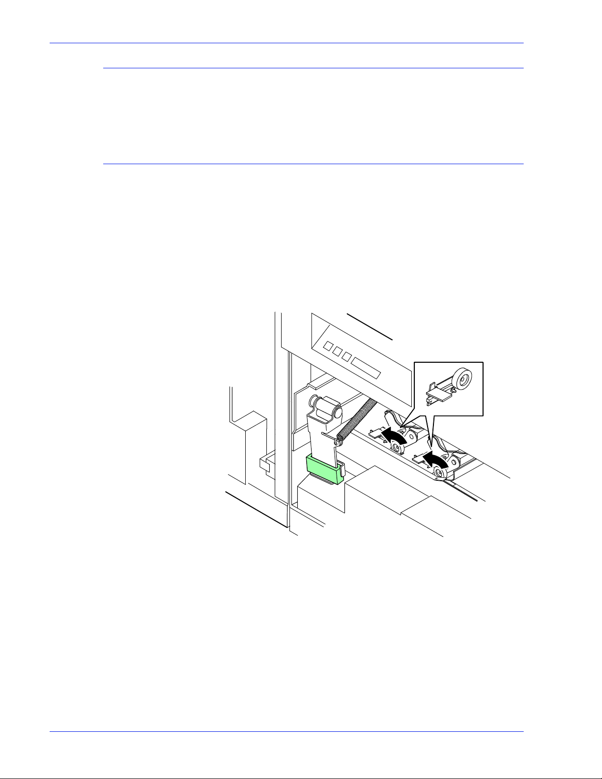
Managing the printer
Powering off the printer immediately
Adjusting the registration transport roll levers for heavy paper
1. Select [Immediate Printer Off] from the Printer menu.
2. Click [Yes] on the confirmation window.
When you use paper that is heavier than 24 pounds/90 gsm, you
must adjust the regi st ration trans port rol l l evers, which ar e loc ated
behind areas 2 and 4.
1. Open the right and left doors of the printer .
2. For each lever:
a. Pull the lever toward you.
b. While holding the lever toward you, turn it to the left.
Figure 2-1 Turning the registration transport roll levers
For systems with small paper (7 by 10-inch/178 by 254 mm)
enablement:
Systems with this option have three levers. To process heavy
papers, turn the levers as shown in the fol lowing figure.
2-2 Operator Guide
Page 57

Managing the printer
Turn to the left
Turn to the right
Turn to the right
Figure 2-2 Three levers in systems with small paper enablement
Loading paper
NOTE: Use the same pressure setting for all levers.
When the job is complete, return the levers to their normal
positions.
NOTE: Positioning may be affected by machine tolerance, the
paper supplier, or job type (for example, duplex).
Your printer may have up to six feeder trays: two processor trays
(trays 1 and 2) and two to four high-cap acit y trays (t rays 3 through
6). Up to six different stocks may be used within a print job,
including oversized cover stock or tabs.
• You can unlock, pull out, and load any tray from which paper is
not being fed, without interrupting printing.
• If you open a tray that is in use, feeding switches to a backup
tray. If no tray is available, printing stops.
• The printer stops feeding p aper from any tray when a ¼-inch/6
mm stack remains in the tray.
1. Unlock the tray that you want to load, using one of the
following methods:
• On the printer: Press the Tray Unlock button on the front
of the tray.
Operator Guide 2-3
Page 58
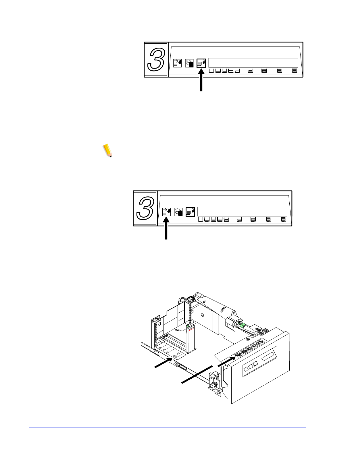
Managing the printer
Figure 2-3 Tray Unlock button on feeder
• At the display monitor: On the Printer Manager window,
Paper Trays tab, right click the tray name. From the
properties pop-up menu, select [Tray Unlock].
NOTE: If the printer stops due to insufficient paper in a tray,
the system unlocks the tray.
2. When the green Ready to Open indicator lights, pull the feede r
tray out until it stops.
Figure 2-4 Ready to Open indicator
3. Place the paper in the tray, following the instructions on the
labels.
1
2
Figure 2-5 Tray labels
2-4 Operator Guide
Page 59

Managing the printer
1. Paper edge guide lines
2. Loading instructions
Do the following:
• Remove any damaged sheets.
• Trays 1 and 2: Load p aper with the wrapper seam side up.
• Trays 3, 4 , 5 and 6: Loa d paper wit h the curl side up. If you
do not see any curl, load the paper with the wrapper seam
side down.
• Fan predrilled paper fan thoroughl y and remove any paper
plugs.
• Load transparencies and 9-in ch / 229 mm tabs into trays 1
and 2 only.
• Ensure that the paper is loaded i nto the right front c orner of
the tray.
CAUTION: Do not load above the MAX line on the paper guide.
Figure 2-6 Maximum fill line
• After loading paper in tray 1 or 2, adjust the rear guide to
touch the paper stack.
• In tray 3, 4, 5, or 6, adjust the rear and side paper guides
to touch the stack.
Operator Guide 2-5
Page 60
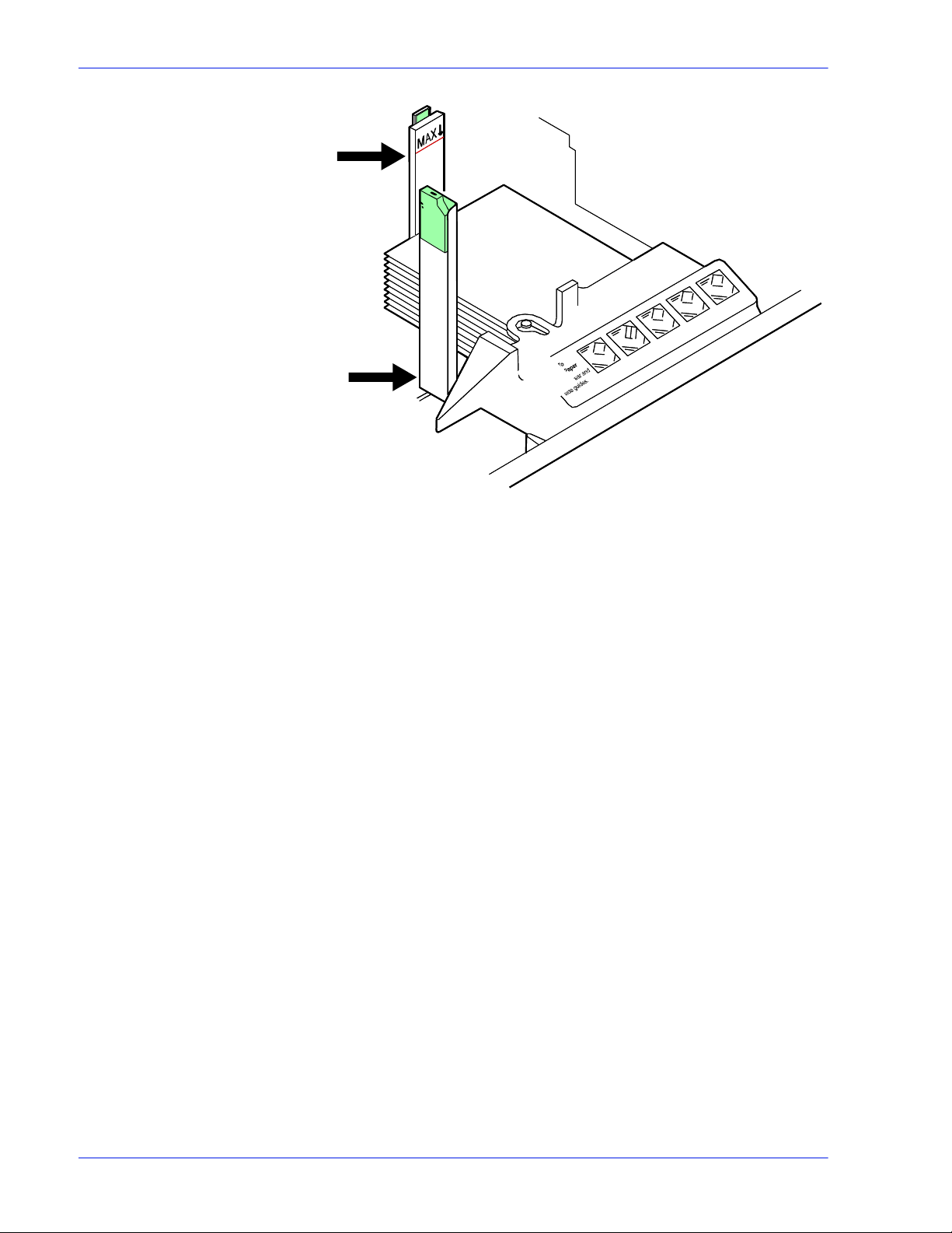
Managing the printer
Figure 2-7 Rear and side guides in trays 3, 4, 5, and 6
2-6 Operator Guide
Page 61
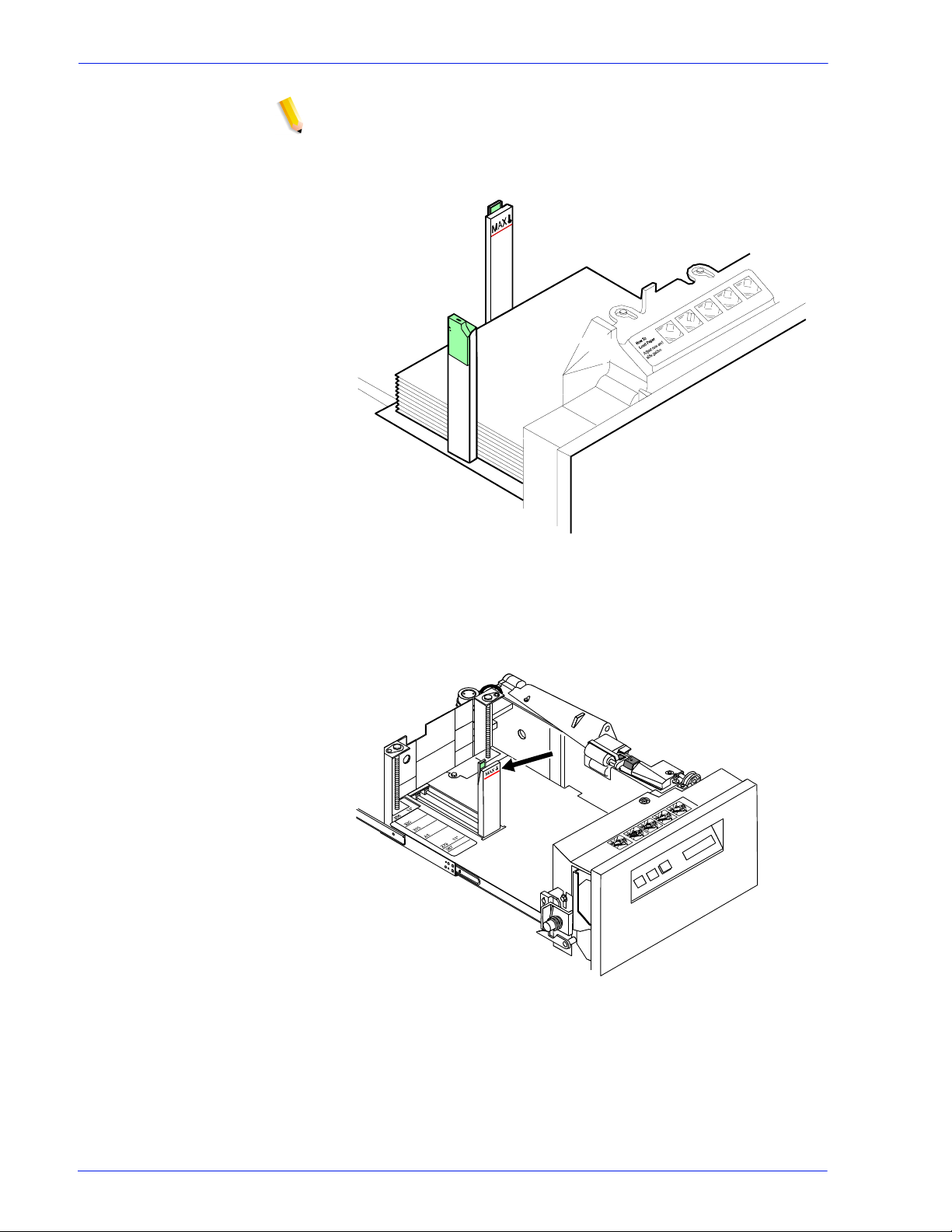
Managing the printer
NOTE: To enable short-edge feed (SEF) for larger papers, load
paper with the short edge against the sid e paper guide and the
long edge against the rear guide.
Figure 2-8 Large paper loaded for shor t edge feeding; for example,
11 by 17 inches / 279 by 432 mm
3. In trays 1 and 2, slide the rear guide until it touches the stack.
Figure 2-9 Slide rear guide to stack
4. Press the green dot on the tray latch until the assembly clicks
into place.
Operator Guide 2-7
Page 62

Managing the printer
5. P u s h the tray in slowly but fi rm l y, until it latches.
CAUTION: Do not slam the tray closed.
6. If the printer has stopped due to low paper, select Continue on
Unloading a stacker bin
Follow this procedure to unload printed output from a stacker bin.
1. Select a bin for unloading by pressing the Bin Unload button
Figure 2-10 Press green dot on tray latch
the display monitor.
on the bin control panel. You can also select a bin for
unloading from the printer mimic on the printer control screen.
Figure 2-11 When a bin is selected, the bin elevator lowers.
2-8 Operator Guide
Page 63
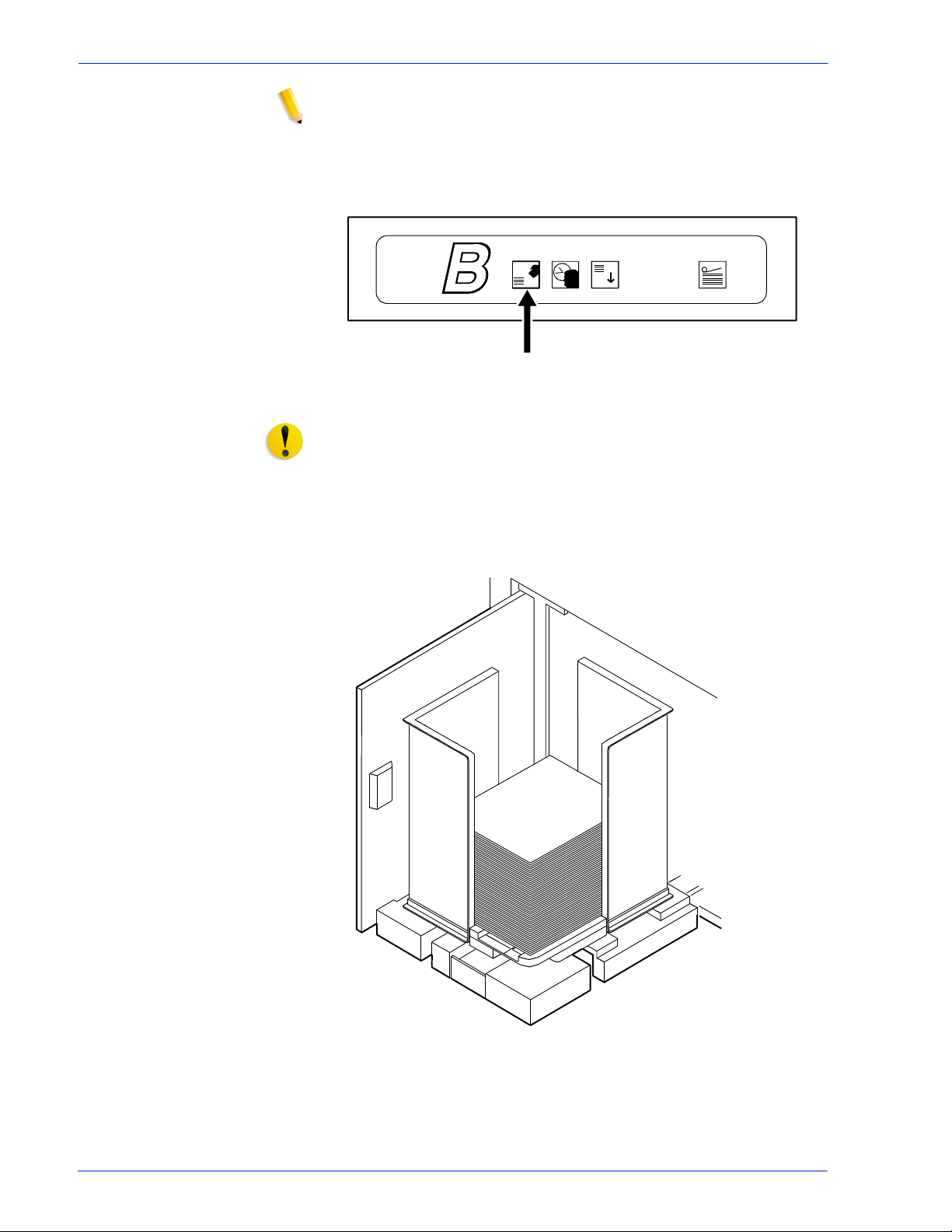
Managing the printer
NOTE: After the bin elevator lowers, the bin cannot be used unt il it
is emptied completely.
2. When the bin elevator stops in the down position, the Ready to
Unload indicator lights.
Figure 2-12 Ready to Unload light
CAUTION: Always use bot h hands to lift a co ntainer or pallet out
of the bin.
3. Open the bin doors, pull the platform out until it stops, and lif t
the container, pallet (for “pallet only” stacking), or paper stack
off the platfor m.
Figure 2-13 Lift container, pallet, or paper stack
4. Carry the loaded container, pallet, or paper stack to a nearby
table or paper cart.
Operator Guide 2-9
Page 64

Managing the printer
5. If you are using a container or pallet, empty it and return it to
the stacker bin.
Points to note for containers:
• The empty container must be the same size as the
previous container if the bin is in an auto switchi ng
combination, or if the print job is not complete and st acking
continues into the bin.
• A different size container may be used if the bin is not
selected for use or is not in an auto switch ing combination.
• To switch from containerless stacking to stacking in a
container or on a pallet (f or “pallet only” stacking), press
and release the green button on top of the stacker bin
platform.
Figure 2-14 Press and release green button
• To switch from stacking into a container or palle t to
containerless st acking, slide the green tab (located on top
of the stacker bin platform) forward until you hear a click.
The following figure shows the green tab locati on.
Figure 2-15 Slide green tab forward
2-10 Operator Guide
Page 65

Managing the printer
6. Firmly push the platform back to its original position and close
the bin doors. The bin elevator rises, and the bin is again
ready for use.
NOTE: The platform does not rise until you have opened and
closed both bin doors.
If the bin is not empty, the elevator remains down, and a
message appears on the display monitor telling you to empty
the bin.
Operator Guide 2-11
Page 66

Managing the printer
2-12 Operator Guide
Page 67

3 Managing the system
This chapter provides management-relat ed information that
pertains to the system as a whole such as starting, stopping, and
rebooting the system and operating the tape drives.
Starting, stopping, and rebooting the system
Shut down and reboot the system only when you are directed in
the “Troubleshooting” chapter of this guide; or after loading new
software, such as Novell NetWare or AppleTalk gateways.
CAUTION: Do not shut down the controller using the Quit option
on the pull-down menu of any window or the Exit option on the
Workspace pop-up menu.
Powering on the controller
Wait at least one minute after power has been switched of f bef ore
continuing. Then switch on power to the controller components in
the following order:
1. Any external SCSI devices, starting with the unit with the SCSI
terminator and following the connection chain toward the Sun
workstation
2. Other peripherals
3. Monitor
4. Sun workstation
When the operating system finishes rebooting, th e Xerox
application software starts. When the DocuSP Print Services
window displays, power on the printer.
Powering on the printer
1. Make sure the printer power cord is securely plugged into the
power receptacle, and the power button is pressed on.
2. Log on as the Administrator or Operator.
3. On the DocuSP Print Services window, select [Printer On]
from the Printer menu.
Operator Guide 3-1
Page 68

Managing the system
Holding queues
Before rebooting or powering off the system, hold all active
queues. A held queue does not release any jobs for printing, nor
accept any jobs that are sent to it.
On the Queue Manager window, do the following for each active
queue:
1. Right click the queue name.
2. From the Properties menu, select [Do Not Accept Jobs] or
[Do Not Release Jobs], as appropriate.
To hold all queues:
1. Right click in the queue list section, and select [Select All]
from the pop-up menu.
2. Right click again in the queue list section and select [Do Not
Accept Jobs].
3. Right click in the queue list section, and select [Do Not
Release Jobs].
Releasing queues
After rebooting or powering on the syst em, release all held
queues.
On the Queue Manager window, do the following for each active
queue:
1. Right click the queue name.
2. From the pop-up menu, select [Accept Jobs] or [Release
Jobs], as appropriate.
To release all queues:
1. Right click in the queue list section, and select [Select All]
from the pop-up window .
2. Right click again in the queue list section, and select [Accept
Jobs].
3. Right click in the queue list section, and select [Release
Jobs].
Rebooting the system (warm boot)
1. On the DocuSP Print Services window, click the [Queue
Manager] icon.
2. Hold all queues. (Refer to “Holding queues,” earlier in this
chapter.)
3-2 Operator Guide
Page 69

Managing the system
3. On the DocuSP Print Services window, select [Exit] from the
System menu. All GUI windows disappear.
4. Open a Terminal window, as follows:
a. Right click on the screen background.
b. From the Workspace pop-up menu, sel ect [Tools].
c. From the Tools menu, select [Terminal].
5. In the Terminal window, log on as root user.
6. Enter:
sync; sync; reboot
7. When the DocuSP Print Service window reopens, log on as
Operator or Administrator.
8. Power on the printer by selecting [Printer On] from the Printer
menu.
9. Release all held queues. (Refer to “Releasing queues,” earl ier
in this chapter.)
Performing a deferred shutdown and reboot
Use this procedure when the system requests a reboot during a
recovery, and you want to wait for queued jobs to finish printing.
1. On the DocuSP Print Services window, log on as
Administrator or Operator.
2. Hold any active queues. (Refer to “Holding queues,” earlier in
this chapter.)
3. On the DocuSP Print Services window, select [Shutdown]
from the System menu.
4. When the DocuSp Print Services window closes and an ok
prompt appears at the bottom of the screen, enter boot.
5. When the DocuSP Print Services window reopens, release all
held queues. (Refer to “Releasing queues,” earlier in this
chapter.)
Performing an immediate shutdown and reboot
Use this procedure when the system requests a reboot during a
recovery without waiting for queued jobs to finish printing.
1. On the DocuSP Print Services window, log on as
Administrator or Operator.
2. Hold any active queues. (Refer to “Holding queues,” earlier in
this chapter.)
3. On the DocuSP Print Services window, select [Immediate
Shutdown] from the System menu.
Operator Guide 3- 3
Page 70

Managing the system
Restarting the DocuSP software
4. Click [Yes] on the confirmation window.
5. When the DocuSP Print Services window closes and an ok
prompt appears at the bottom of the screen, enter boot.
6. When the DocuSP Print Services window reopens, release all
held queues. (Refer to “Releasing queues,” earlier in this
chapter.)
1. On the DocuSP Print Services window, log on as
Administrator or Operator.
2. Hold any active queues. (Refer to “Holding queues,” earlier in
this chapter.)
3. On the DocuSP Print Services window, select [Restart] from
the System menu.
4. Wait for the DocuSP Print Services window to close and
reopen.
5. Release all held queues. (Refer to “Releasing queues,” earl ier
in this chapter.)
Powering off the system
You may be required to power down the system under the
following conditions:
• Work is being done on an attached printer.
• The Sun workstation is being moved.
• SCSI peripherals are being added or removed.
• A power outage is planned.
• The Sun workstation is receiving hardware maintenance.
• The DocuSP controller will not be in use for an extended
period.
The Sun workstation should run continuously. Refer to the Sun
hardware manuals for recommendati ons for when to power of f the
system.
CAUTION: Do not sh ut down DVD players and SCSI t ape drives
unless you are powering off the entire system.
1. Log on as Administrator or Operator.
2. Hold any active queues. (Refer to “Holding queues,” earlier in
this chapter.)
3. Select [Printer Off] from the Printer menu.
4. Select [Shutdown] from the System menu.
3-4 Operator Guide
Page 71

5. Click [Yes] on the confirmation window.
6. When the DocuSP Print Services window closes and an ok
prompt appears at the bottom of the screen, switch off power
to the computer components in the following order:
a. Any external SCSI devices, such as disk drives, tape
drives, or DVD players
b. Any other peripheral devices, such as modems
c. Sun workstation
d. Monitor
7. When the DocuSP software is running again, resubmit any
documents that had not completed printing.
Performing an emergency power off
Disconnect the power cable from the power outlet immediately
after powering off , and contact your Xerox service representative.
Use this procedure to switch off power quickly if any of the
following occurs:
Managing the system
• The equipment emits unusual odors or makes unusual noises.
• The power cable is damaged or frayed.
• A wall panel circuit breaker, fuse, or other safety device is
switched.
• Liquid is spilled into the equipment.
• The equipment is exposed to water damage or flooding.
• Any part of the equipment is damaged.
Powering off the controller
CAUTION: This procedure may corrupt the DocuSP software or
result in data loss. Use it only in emergency.
1. On the DocuSP Print Services window, select [Immediate
Shutdown] from the System menu.
2. After the DocuSP Print Services window has closed, shut off
the power to the controller by one of the following methods:
• Switch off the controller power switch, located on the front
of the processor.
• Grasp the controller plug firmly and pull it from the wall
outlet.
Warning: Do not grasp the cable to pull out the plug.
• Switch off the controller power strip.
NOTE: This method powers off everything that is plugged into
the power strip, including the processor, monitor, QIC tape
drive, 36-track tape dri ve, and external hard disk drive.
Operator Guide 3- 5
Page 72

Managing the system
Powering off the printer
1. Power off the controller.
2. Shut off power to the printer by one of the following methods:
• Open the right front door of the printer and press the power
button.
Figure 3-1 Shutting off power
• (U. S. only) Grasp the printer plug firmly and pull it from t he
wall outlet.
WARNING: Do not grasp the cable to pull out the plug.
• Open the left door of the printer, and push down circuit
breakers CB101, CB102, and CB103.
3-6 Operator Guide
Page 73

Managing the system
Figure 3-2 Circuit breaker locations
Operating the 18/36 track tape drive
The external 18/36 track tape drive uses 1/2-inch cartridge tapes.
You can use it to load resources and to submit offline print jobs.
Powering on the tape drive
Press the Power button on the front of the drive.
The drive displays the name of each diagnostic test while
performing it.
Operator Guide 3- 7
Page 74
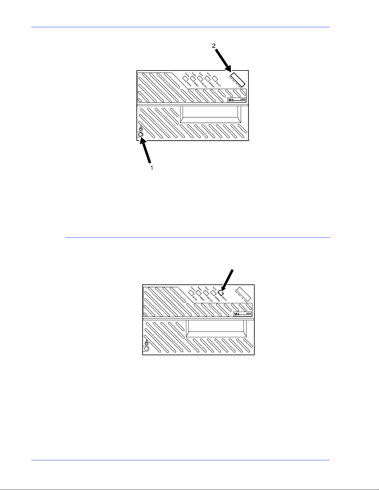
Managing the system
Figure 3-3 Press the power button and display diagnostic test
1. Power switch
2. Message display
Powering off the tape drive
1. Press the Ready button.
Figure 3-4 Ready button
2. Unload any tape cartridge.
3. Press the Power button.
3-8 Operator Guide
Page 75

Figure 3-5 The Power button
Placing the tape drive online
1. Load a tape cartridge in the drive.
Managing the system
Loading a tape
2. Press the Ready button.
If a tape is loaded but the drive is not online, press the Ready
button to place the drive online.
Before loading a tape, check the cartridge for damage.
CAUTION: A damaged cartridge can prevent the tape from
threading correctly and can damage the tape drive.
Do not load a cartridge if:
• The case is cracked or broken.
• The leader block (the blank section at the beginning of the
tape) or its latch is broken.
• The file protect selector or sensor is damaged.
• The label is peeling.
• The case contains any liquid.
• The tape was wound completely out of the cartridge, then
reattached to the cartridge reel.
If a cartridge is damaged, substitute one that contains a backup
version of the data.
1. Hold the cartridge with the smooth side on top and the leader
block toward the drive.
Operator Guide 3- 9
Page 76

Managing the system
Figure 3-6 Hold the cartridge
CAUTION: Never force a car tr idge into the tape drive.
2. Slide the cartridge into the entry slot of the tape drive until it
stops.
Figure 3-7 Slide cartridge into entry slot
After about 15 seconds, the tape is loaded. The message window
displays Online, and indicates whether the cartridg e is fi le
protected (F) or unprotected (U).
Unloading a tape
Automatic
procedure
3-10 Operator Guide
When a job is finished, the tape drive rewinds th e tape and
unloads and ejects the cartridge.
Page 77

Managing the system
Manual procedure 1. Press the Ready button to take the tape drive offline.
2. Press the Unload button.
Figure 3-8 The Unload and Ready buttons
1. Unload button
2. Ready button
The message window indicates when the tape drive is rewinding
or unloading.
Guidelines for handling cartridges
• Never pry open the feed slot door of the tape driv e.
• Never force a tape cartridge into or out of the tape drive.
• Never leave a cartridge in the tape drive while powering off.
This could damage data on the tape and the tape dri ve
components.
• Store cartridges vertically in a clean area that has the same
temperature and humidity as the tape drive location.
• If the storage environment is dif fe rent, bring the cartridges i nto
the tape system environment 24 hours before using them.
• Never remove the protective wrapping until you are ready to
use the cartridge.
• Every time you pick up a cartridge, ensure that the leader
block is latched.
• Never carry two or more cartridges loose in a container .
Leader blocks can snag on other cartridges and unlatch.
• Keep cartridges clean and dry.
• Never release a leader block and pull tape from a cartridge.
• Never open a cartridge.
• Never expose tape or a cartridge to direct sunlight.
• Never smoke near the tape drive or cartri dge storage areas.
Tobacco smoke and ash are damaging to tapes.
Operator Guide 3- 11
Page 78

Managing the system
• Never place cartridges near electric motors or any other
magnetic sources that may erase data.
• To clean a cartridge, wipe off dust, dirt, and moisture with a
lint-free cloth.
• If you must use a cleaning solution, make sure it i s formulated
for tape cartridges. Never all o w the solution to touch the tape.
• If a leader block comes off and there is no other damage, you
can use a leader block repair kit to reatt ac h the bl ock. You can
then use the cartridge one more time to copy the data onto a
new cartridge.
• If a label starts to peel, replace it immediately.
• Do not write on a label that is on a cartri dge. Writ e a new label,
remove the old one, and replace it with the new one.
• Place the two labels in the recessed areas of the cart ridge as
shown below:
Figure 3-9 Placement of labels
1. Customer label on top
2. Volume/serial number label opposite side of thumbwheel
• Write on labels with markers that do not smear .
• Use only labels that leave no residue when removed.
Setting file protection
To make a tape read-only, turn the thumbwheel on the side of the
cartridge until a white dot appears in the window.
To enable writing to the tape, turn the thumbwheel until the dot is
not visible.
3-12 Operator Guide
Page 79

Figure 3-10 File protection dot
Printing the online Help documentation
You can print out the entire set of Help documentation screens
from the controller as a single document.
1. From the Help pull-down menu, select [Print Help
Documentation...].
Managing the system
2. On the Print Help Documentation window, select from the
Queue menu the queue to which you want to send the Help file
to print.
3. Click [OK]. The printer prints out the entire set of Help
windows.
Operator Guide 3- 13
Page 80

Managing the system
3-14 Operator Guide
Page 81

Paper care
Storing paper
4 Maintaining the system
This chapter provides information on paper care, on adding and
replacing consumable supplies such as dry ink, and on cleaning
the various areas of the system, including the tape drives.
Correct storage and handling of media prevents jams and del ays,
and ensures optimum productivity.
It is important to store paper correctly. Temperature and humidity
affect the way your printer pr ocesses paper. S tore paper in the
cartons it came in. To reduce the possibility of moisture
absorption, always place cartons on a wooden p allet or store them
in a cabinet off the floor.
After removing the paper from its carton, always store it:
• In its wrapper
• On a flat surface
• In a closed cabinet
• In a cool, dry area
• In 68 to 76oF / 20 to 24.4oC
• In 35% to 55% humidity
Operator Guide 4-1
Page 82

Maintaining the system
Figure 4-1 Storing paper correctly
Figure 4-2 Recommended temperature and humidity for
paper storage
4-2 Operator Guide
Page 83

Conditioning paper
Because temperature and humidity affect paper performance in
the printer, you need to condition paper before using it. To
condition paper, store it for a specified length of time in the same
type of environment as your printer.
The length of time you should condition your paper depends on
the amount of paper and the dif fer ence between the storage and
operating temperatures.
Use the following chart to determine the number of hours needed
to condition stacked cartons of paper.
NOTE: The numbers in the top two rows indicate the temperature
difference between the storage area and the operating
environment, not actual room temperatures .
Table 4-1 Temperature and hours needed to condition paper
Maintaining the system
T emperature difference between storage and operating areas
Fahrenheit
10
o
15
o
20
o
25
o
30
o
40
o
50
o
Centigrade
5.5
o
8.5
o
11
o
13
o
17
o
22
o
28
o
Cartons Hours needed to condition the paper
1 4 8 11 14 17 24 34
5 5 9 12 15 18 25 35
10 8 14 18 22 27 38 51
20 11 16 23 28 35 48 67
40 14 19 26 32 38 54 75
Example: If you want to mov e ten carton s of p aper f rom a stora ge
area with a temperature of 90
temperature of 70
o
F (a 20o difference), you should do so at least
o
F to an operating area with a
18 hours before using the paper.
Paper curl
Before the manufacturer cuts paper into sheets, it is stored on
large rolls. After it is cut and packaged, it ret a ins some of the curl
from the rollers.
Although it is unnecessary to load paper with the curl facing up or
down, best result s occur when you are c onsistent. For example, if
you open paper with the wrapper seam up, always load i t in the
tray that way.
Operator Guide 4- 3
Page 84

Maintaining the system
Using consumables
Adding fuser agent
The following tasks are part of maintaining your system:
• Adding fuser agent
• Replacing the dry ink waste container
• Replacing the dry ink cartridge
• Using the custom transfer assist blade
WARNING: Fuser agent contains silicone, whi ch can cause
irritation upon contact with the eyes. Be sure to wash your hands
with soap and water after you finish this procedure.
To add fuser agent:
1. Open the right and left doors of the printer an d locate the fuser
area.
Figure 4-3 The fuser area
2. Place a dropcloth on the floor under the fuser area.
3. Grasp the green handle on the fuser drawer and pull it out unt il
it stops.
4-4 Operator Guide
Page 85
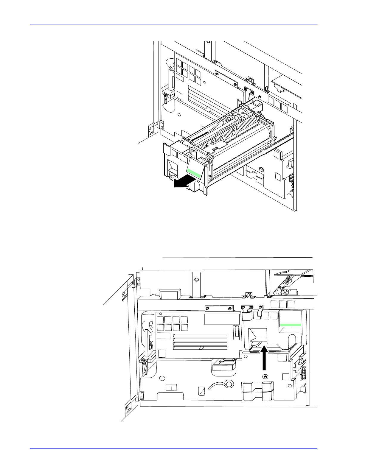
Maintaining the system
Figure 4-4 Pull out fuser drawer
4. Locate the fuser agent reservoir.
Figure 4-5 The fuser agent resevoir
Operator Guide 4- 5
Page 86

Maintaining the system
5. Pull the fuser agent reservoir out until it stops.
6. Remove the reservoir cap by turning it counterclockwise.
7. Remove the cap from a new bottle of fuser agent.
WARNING: If any fuser agent spills on the floor, remove it
immediately. Fuser agent spills make the floor slippery.
CAUTION: The fuser reservoi r has an antisplash seal. Do not
push the fuser agent bottle i nto the reser voir wit h exces sive f orce,
as this can damage the seal.
8. Carefully pour the fuser agent into the reservoir, until the level
reaches the MAX line.
Figure 4-6 Pour fuser agent to MAX line
9. Replace the reservoir cap by turning it clockwise.
10. Push the fuser agent reservoir in until it stops.
11. Push the fuser drawer in until it latches in place.
4-6 Operator Guide
Page 87
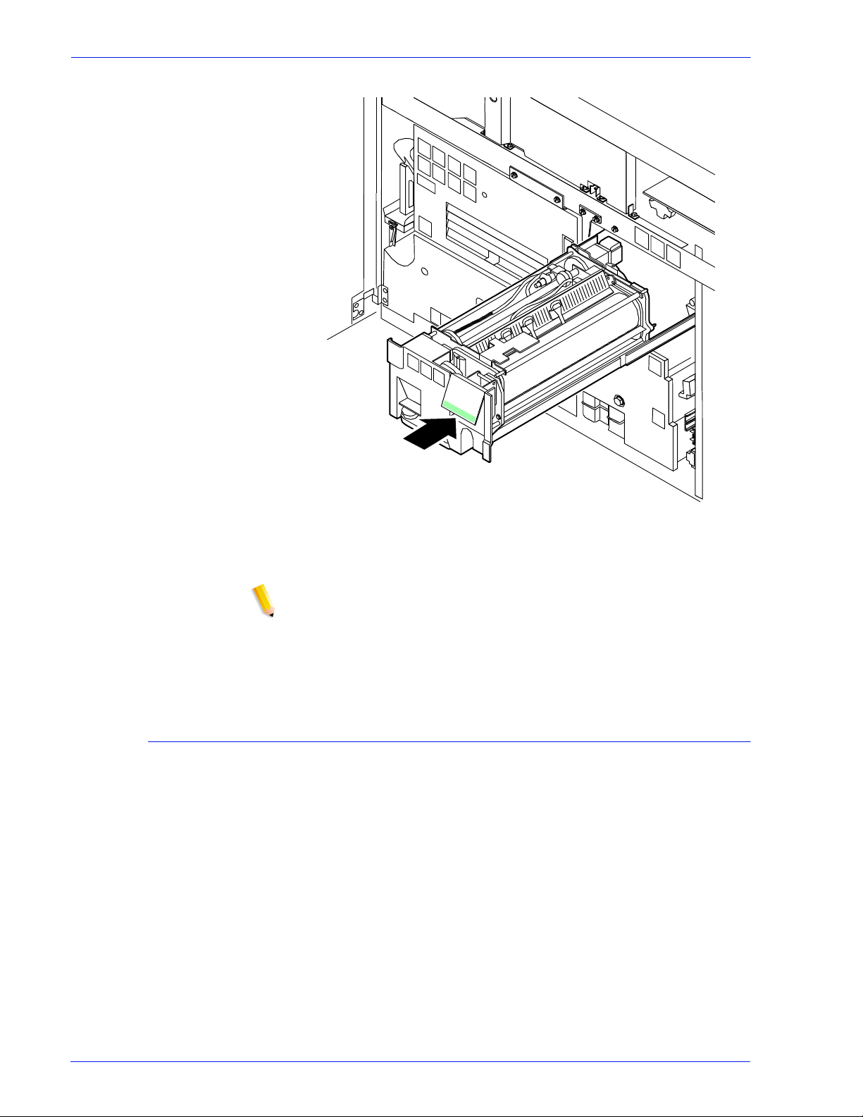
Maintaining the system
Figure 4-7 Push in fuser drawer
12. Close the printer doors.
NOTE: The fuser agent message disappears after the system
prints between 32 and 40 sheets. Because the sheets must be
processed continuously, you may want to run 45 test pages in
order to clear the message from the system (unless the current
print job contains at least 40 pages).
Replacing the dry ink waste container
To replace the dry ink waste container:
1. Open the right and left doors of the printer and locate the dry
ink waste container.
Operator Guide 4- 7
Page 88
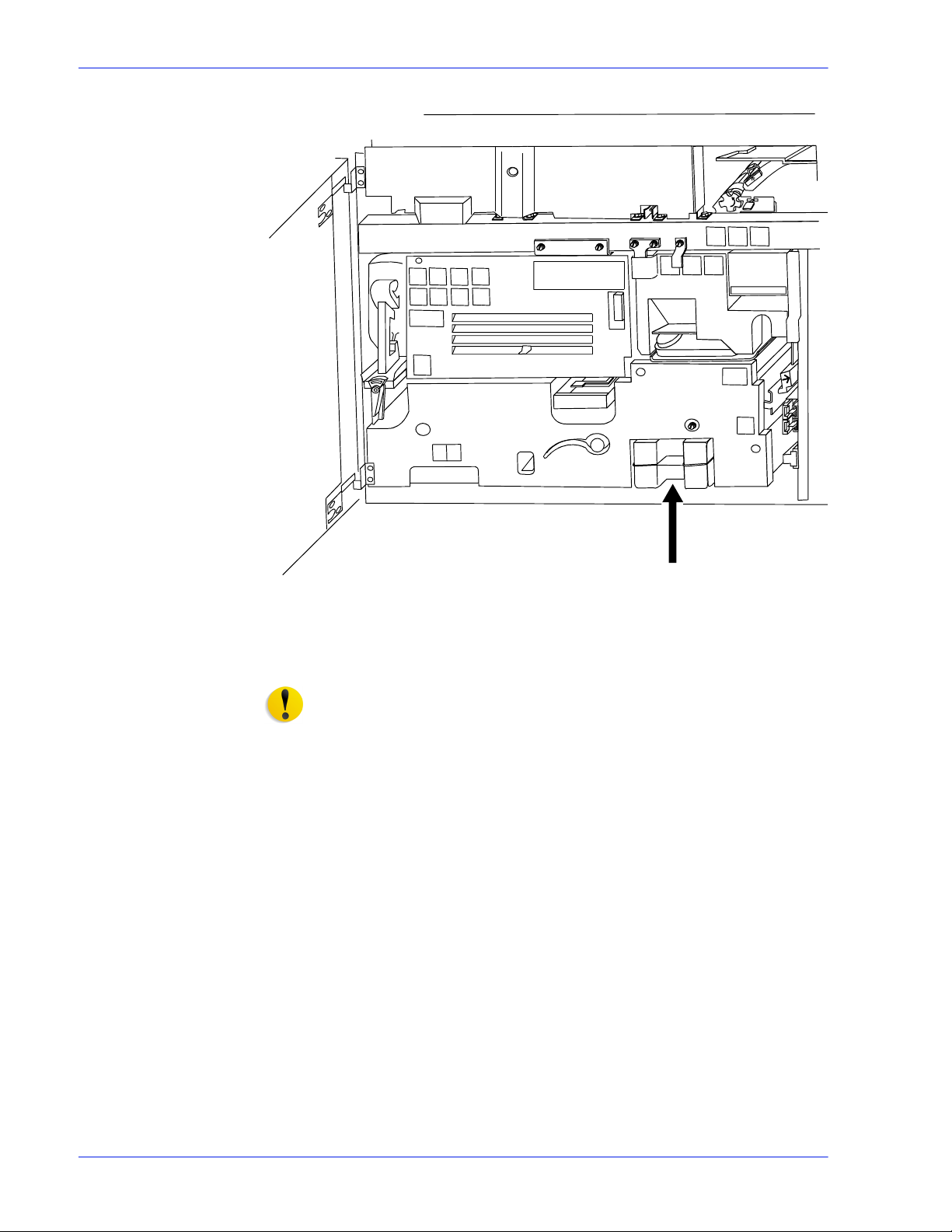
Maintaining the system
Figure 4-8 Dry ink waste container
2. Place a dropcloth on the floor under the dry ink waste
container area.
CAUTION: To prevent dry ink spills, do not tip or tilt the waste
container.
3. Pull the full waste container out of the printer.
4-8 Operator Guide
Page 89

Maintaining the system
Figure 4-9 Pull out waste container
4. Remove the cap from the top of the full waste container.
Figure 4-10 Remove cap
5. Place the removed cap over the opening on the end of the full
waste container.
Operator Guide 4- 9
Page 90
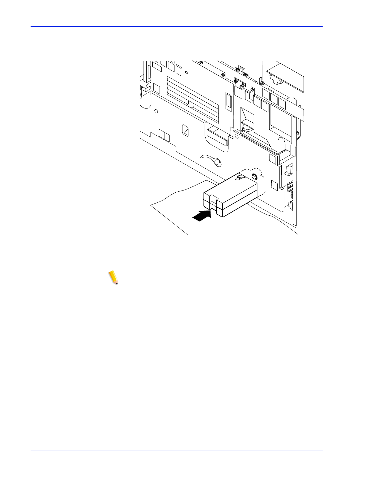
Maintaining the system
6. Slide a new, empty, dry ink waste container into the printer
until the container stops.
Figure 4-11 Slide in new waste container
7. Close the printer doors.
NOTE: If any dry ink gets on your hands, wash them with soap
and cold water. Heat sets the ink permanently. If any dry ink
gets on your clothes, brush them with a dry paper towel or a
stiff bristled brush. I f this does not remove the ink i mmediately,
launder with detergent and cold wat er. Dry cleaners should be
told that the spot is dry ink for a printer, so they do not use a
solvent that sets the stain.
4-10 Operator Guide
Page 91

Replacing the dry ink cartridge
CAUTION: To prevent dry ink spillage, remove the cartri dge onl y
when directed to do so by a message on the display monitor.
To replace the dry ink cartridge:
1. Open the right and left doors of the printer and locate the dry
ink area at the left side of the printer. There are step by step
instructions on the panel next to the dry in k cartridge.
Maintaining the system
Figure 4-12 Locate dry ink area
2. Place a dropcloth on the floor under the dry ink area.
3. Pull the empty dry ink cartridge out until it stops.
4. Move the green handle to the right (the unlatched position) to
release the cartridge and lid.
Operator Guide 4- 11
Page 92

Maintaining the system
Figure 4-13 Move green handle to right
5. Remove the empty cartridge and discard it.
6. Turn a new, full ca rtridge of dry ink upside down and shake it
well to loosen the contents thoroughly.
7. Insert the new cartridge into the printer until it stops.
Figure 4-14 Insert new cartridge
8. Move the green handle to the left (the latched position) to
secure the lid of the cartridge.
4-12 Operator Guide
Page 93
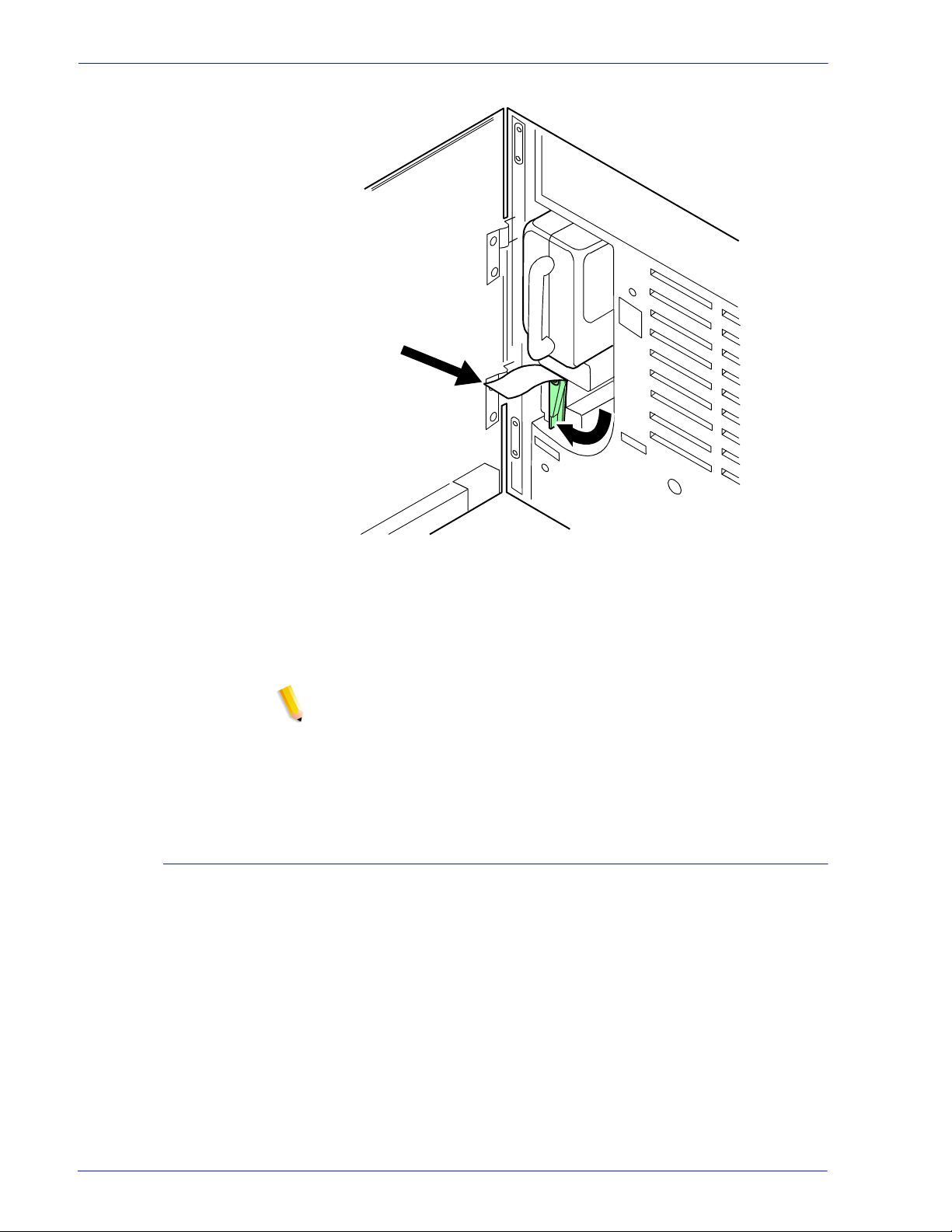
Maintaining the system
Figure 4-15 Move green handle to left
9. Hold the cartridge in place and pull off the paper seal.
10. Discard the seal along with the drop cloth.
11. Close the printer doors.
NOTE: If any dry ink gets on your hands, wash them with soap
and cold water. Heat sets the ink permanently. If any dry ink
gets on your clothes, brush them with a dry paper towel or a
stiff bristled brush. I f this does not remove the ink i mmediately,
launder with detergent and cold wat er. Dry cleaners should be
told that the spot is dry ink for a printer, so they will not use a
solvent that sets the stain.
Using the custom transfer assist blade
The custom transfer assist blade in the printer assures good print
quality for your jobs. A kit is available allowing you to customize
the transfer assist blade for use with nonstandard paper sizes.
You cannot use the custom transfer assist blade for pr int jobs that
use more than one paper size. In addition, the following paper
lengths cannot use the blade:
• In U.S. markets
– 11.1 to 11.4 inches/282 to 290 mm
– 11.8 to 12.1 inches/300 to 307 mm
– 13 to 13.5 inches/330 to 343 mm
• In non-U.S. markets
Operator Guide 4- 13
Page 94
Maintaining the system
– 11.1 inches to 11.4 inches/282 to 290 mm
– 11.8 inches to 12.1 inches/300 to 307 mm
NOTE: With these paper sizes, transfer efficiency may be
reduced.
CAUTION: To avoid damage to the photoreceptor, you must
perform the Setting tray size with the tr ansfer assist blade
Installing the
custom transfer
assist blade
Setting tray size with
the custom transfer
assist blade
The custom transfer assist blade comes in a package containing
detailed instructions. Be sure you follow the instructions carefully.
CAUTION: To prevent damage to the system, have your service
representative show you the procedur e before you attempt to
customize and install a transfer assist blade for the first time.
When you are using the custom transfer assist blade, you must
set the tray length. Use the following two tables to determine the
tray length setting to use.
T able 4-2 US tray length settings for custom transfer assist blades
Paper Size Set Paper Size to
11.5 to 11.7 inches/292 to 297 mm 11.7 inches/297 mm
12.1 to 12.9 inches/307 to 328 mm 13 inches/330 mm
13 to 13.9 inches/330 to 353 mm 14 inches/356 mm
Table 4-3 Non-US tra y length s ettings for custom transfer
assist blades
Paper Size Set Paper Size to
10 to 10.9 inches/254 to 277 mm 11 inches/279 mm
11.5 to 11.6 inches/292 to 294 mm 11.7 inches/297 mm
12.1 to 12.9 inches/307 to 328 mm 13 inches/330 mm
Cleaning the system and its components
Cleaning tasks consist of the following:
• Cleaning the 18/36-track cartridge tape drive
• Cleaning the 26-track cartridge tape drive
• Cleaning the DVD drive
• Cleaning the diskette drive
4-14 Operator Guide
Page 95

• Cleaning the sensors and the reflecting surfaces
• Cleaning the display
• Cleaning the exterior surfaces of the system
Cleaning the 18/36-track cartridge tape drive
A cleaning cartridge is shipped with each 18/36-t rack cartridge
tape drive. This cartridge should be replaced after 500 uses.
When the tape drive needs to be cleaned, CLEAN appears in the
message display after a cart ridge is unl oaded and during a rewi nd
or locate operation.
NOTE: CLEAN is a status message, not an error message.
CAUTION: Never power off the tape drive without following the
cleaning procedure once the CLEAN message has appeared.
Maintaining the system
To clean the 18/36-track cartridge tape drive read/write heads:
CAUTION: The cleaning cartridge must be undamaged and
clean.
1. Remove any cartridge loaded in the tape drive.
2. Insert the cleaning cartridge.
The cleaning cycle takes approximately 15 seconds.
3. Remove the cleaning cartridge when it is unloaded.
4. Mark the usage on the tape label. Do not use a grease pencil.
You must clean the 18/36-track cartridge tape drive regularly to
keep it functioning properly.
Cleaning the 26-track cartridge tape drive
The 26-track, or quarter inch cartridge ( QIC ) tape drive heads
should be cleaned at least once a week. If you use the drive for
eight hours or more per day, then you should clean the drive daily.
The process is simple and requires very little time.
1. If there is a cartridge in the tape drive, remove it.
2. Insert the cleaning cartridge into the tape drive and close the
door. Cleaning begins automatically once the cartridge is
inserted.
3. Allow the tape to run for approximately 30 seconds, then
remove it.
Operator Guide 4- 15
Page 96

Maintaining the system
Cleaning the DVD drive
Cleaning the diskette drive
NOTE: Replace the foam pad on the cleaning cartri dge af ter i t
has been used three times. The cleaning cartridge itself can
be used approximately 100 times.
Follow the DVD cleaning directions and recommended cleaning
frequency.
1. If there is a DVD disk in the drive, remove it.
2. Follow the directions to clean the DVD drive.
The floppy disk drive must be cleaned at recommended intervals
to prevent read and write errors.
To clean the diskette drive:
1. If there is a diskette in the floppy disk drive, remove it.
2. Insert the cleaning diskette into the disk drive.
3. Follow the directions on the cleaning diskette to clean the
diskette drive.
4. Remove the cleaning diskette.
Cleaning the sensors and the reflecting surfaces
The following is a list of sensors to clean:
• Q850 sensor
• Q1011 sensor and mirror
• Q1106 sensor
• Q1166 sensor
• Q1107 sensor
• Q1164 sensor
Cleaning the Q850 sensor
Follow this procedure when directed by Xerox Customer Support
Center personnel.
1. Open the right and left doors of the printer and locate area 4.
2. Raise the area 4 green handle until it locks into place.
4-16 Operator Guide
Page 97
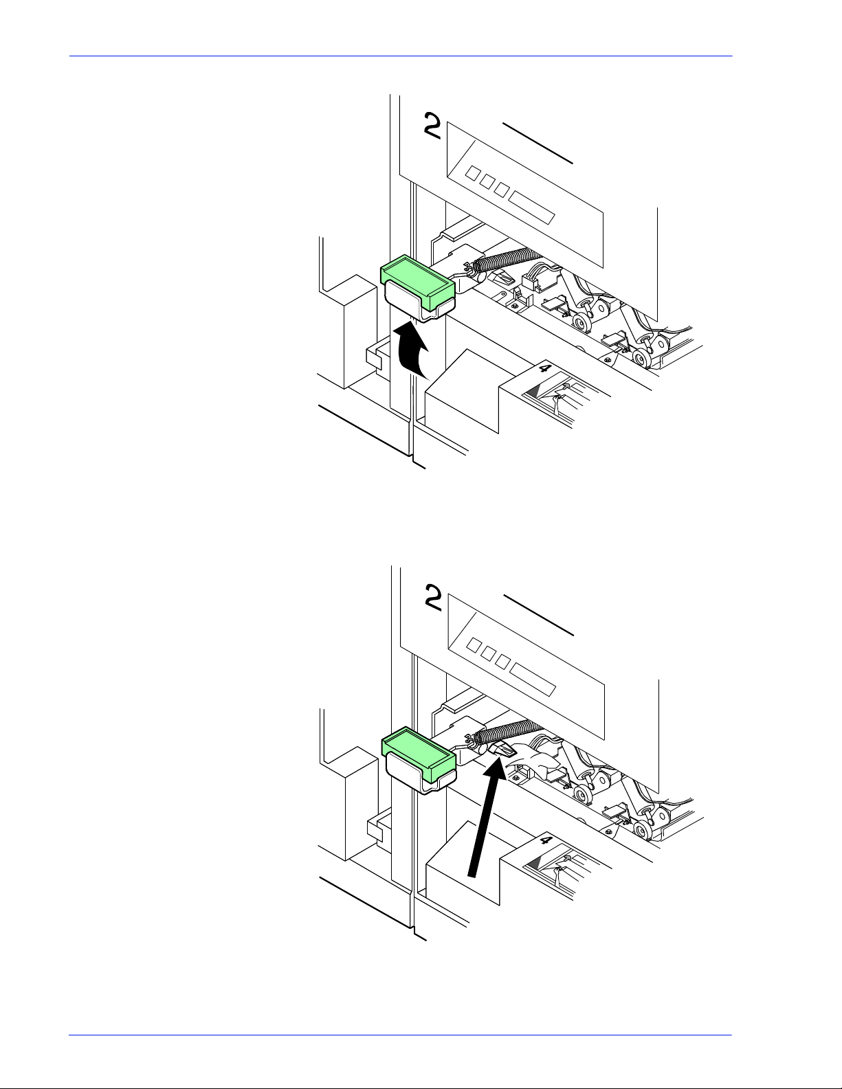
Maintaining the system
Figure 4-16 Raise area 4 green handle
3. Locate the Q850 sensor.
Figure 4-17 Q850 sensor
Operator Guide 4- 17
Page 98

Maintaining the system
4. Place a dry cleaning pad on the sensor and move it from left to
right to clean the sensor.
5. Lower the area 4 green handle.
6. Close the printer doors.
Cleaning the Q1011 sensor and mirror
Follow this procedure when directed by Xerox Customer Support
Center personnel.
1. Open the right and left doors of the printer and locate the
Q1011 sensor.
Figure 4-18 Q1011 sensor
2. Apply a small amount of lens and mirror cleaner to a cleaning
pad.
3. Wipe the sensor and mirror gently with the cleaning pad.
4-18 Operator Guide
Page 99

Maintaining the system
Figure 4-19 Gently wipe sensor and mirror
Cleaning additional sensors
There are additional sensors that you should clean when directed
by Xerox Customer Support Center personnel.
NOTE: If the sensor is very dirty, you may use a small amount of
alcohol on a swab to clean it.
CAUTION: Do not use any abrasive materials or stronger
solvents on the sensor.
Operator Guide 4- 19
Page 100

Maintaining the system
Cleaning the Q1106 and Q1166 sensors
To access sensors Q1106 and Q1166, open the top cover of the
high capacity stacker.
To clean the sensors:
1. Brush or wipe the sensor windows lightly.
2. Remove any paper dust present in the area.
Figure 4-20 Remove paper dust
Cleaning the Q1107 sensor
To access sensor Q1107, open the top cover of the high capacity
stacker.
To clean the sensor:
1. Brush or wipe the sensor window lightly.
2. Remove any paper dust present in the area.
4-20 Operator Guide
 Loading...