

Xerox Phaser 220e, Phaser 300, Phaser 200i, Phaser 220i, Phaser PXPhaser PXiPhaser II PXPhaser II PXiPhaser II PXePhaser II SX Instruction Sheet
...Page 1

Instruction Sheet
Phaser™ PX
Phaser™ PXi
Phaser™ II PX
Phaser™ II PXi
Phaser™ II PXe
Phaser™ II SX/DX
Phaser™ IISD/SDX
Phaser™ III PXi
Phaser™ 300i
Phaser™ 200i and 220i
Phaser™ 200e and 220e
4-Mbyte RAM SIMM Installation — (4690F4M)
Finding your printer's SIMM installation instructions
If your printer is a ... Then go to page ...
Phaser PX 2
Phaser PXi 2
Phaser II PX 6
Phaser II PXi (slide-in style image processor board) 6
Phaser II PXe 9
Phaser II PXi (bolt-down style image processor board) 9
Phaser III PXi and Phaser 300i 12
Phaser II SX/DX (slide-in style image processor board) 14
Phaser II SX/DX (bolt-down style image processor board) 17
Phaser IISD/SDX 20
Phaser 200i and 220i 23
Phaser 200e and 220e 23
Copyright
1993 by Tektronix, Inc.. All rights reserved. 063-1113-AH
©
Slide-in style image processor board
(note the four thumbscrews)
Bolt-down style
image processor board
Page 2

4-Mbyte RAM SIMM Installation — (4690F4M)
Static electricity precautions
■
Leave the printer plugged into its power outlet. This preserves a
ground path for static discharges.
■
Touch the printer's bare metal frame often to discharge static
electricity from your body.
■
Handle the circuit board(s) by their edges only.
■
Do not lay the board(s) on a metal surface.
■
Make the least possible movements to avoid generating static
electricity.
■
Avoid wearing nylon or polyester clothing; they generate static
electricity.
Phaser PX
Phaser PXi
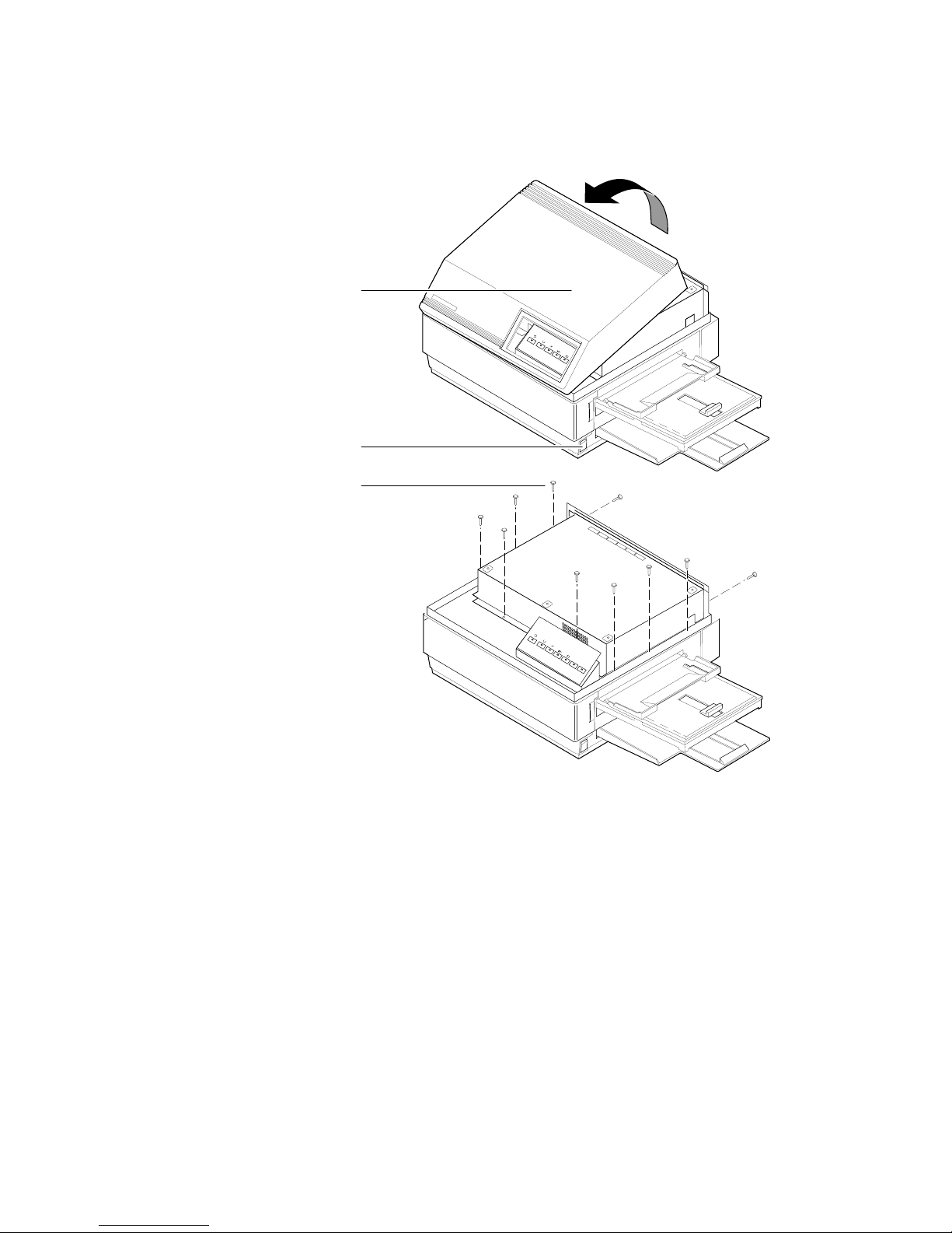
1.
Power down the printer. Do not unplug the printer; this preserves a
ground path to dissipate static charges. Disconnect the host interface
cables.
2.
Remove the printer’s upper half cover by first lifting the rear corners
of the cover and then the front corners.
2
Page 3
4-Mbyte RAM SIMM Installation — (4690F4M)
Remove the EMI shield.
3.
2
1
3
3
Page 4
4-Mbyte RAM SIMM Installation — (4690F4M)
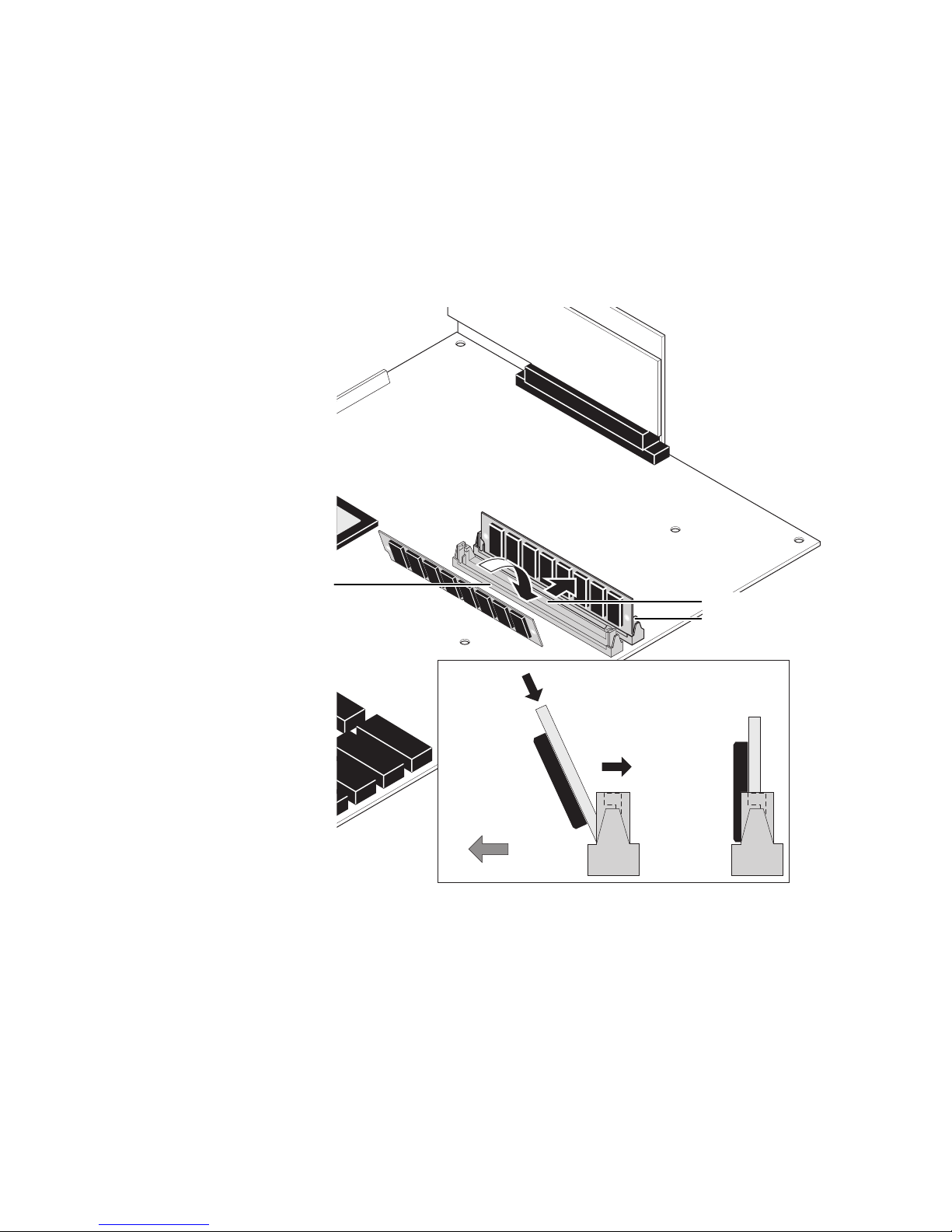
PX image processor: Locate the RAM SIMM connector on the image
4.
processor board. It is labeled J229 (on older-version boards it is
labeled J335).
Insert the RAM SIMM in J229 (or J335).
a.
b.
Angle the RAM SIMM into its connector; it should lock in place
when properly installed.
4
RAM chips
face to the
front of
printer
a
Front of printer
J7 (PXi)
J6 (PXi)
J229 or J335 (PX)
b
Insert SIMM
. . .and. . .
tilt back
until it
locks in
place
4
Page 5
4-Mbyte RAM SIMM Installation — (4690F4M)
Note
For the PXi image processor: Install memory modules in the order J6
and then J7.
PXi image processor: Insert a DRAM SIMM in connector J6 (or in J7 if
J6 is already filled) (
place (
b
). Repeat Step 4 to install additional memory modules.
a
), and tilt the module upright until it locks in
When properly inserted, a tab on each end of the connector slips into a
hole on each end of the RAM SIMM. Also, a pawl on each end of the
connector latches around each end of the RAM SIMM to lock it
in place.
4
PHASER II PXi
MODEL 4694PXI
Serial
(RS-232)
12345 6 7
Reset
Extended
Run
AppleTalk
Diagnostics
Power Up
Input
®
Skip
Startjob
Run
Metric
Paper Size
American
1200
89
Baud Rate
Variable
Status
J6
J7
J8
Parallel
ab
SCSI Disk
5.
Reinstall the EMI shield and the top panel.
6.
Reconnect the host interface cables. Turn on the printer and make a
print to ensure that the printer functions correctly.
5
Page 6
4-Mbyte RAM SIMM Installation — (4690F4M)
Phaser II PX
Phaser II PXi
(slide-in style image processor board)
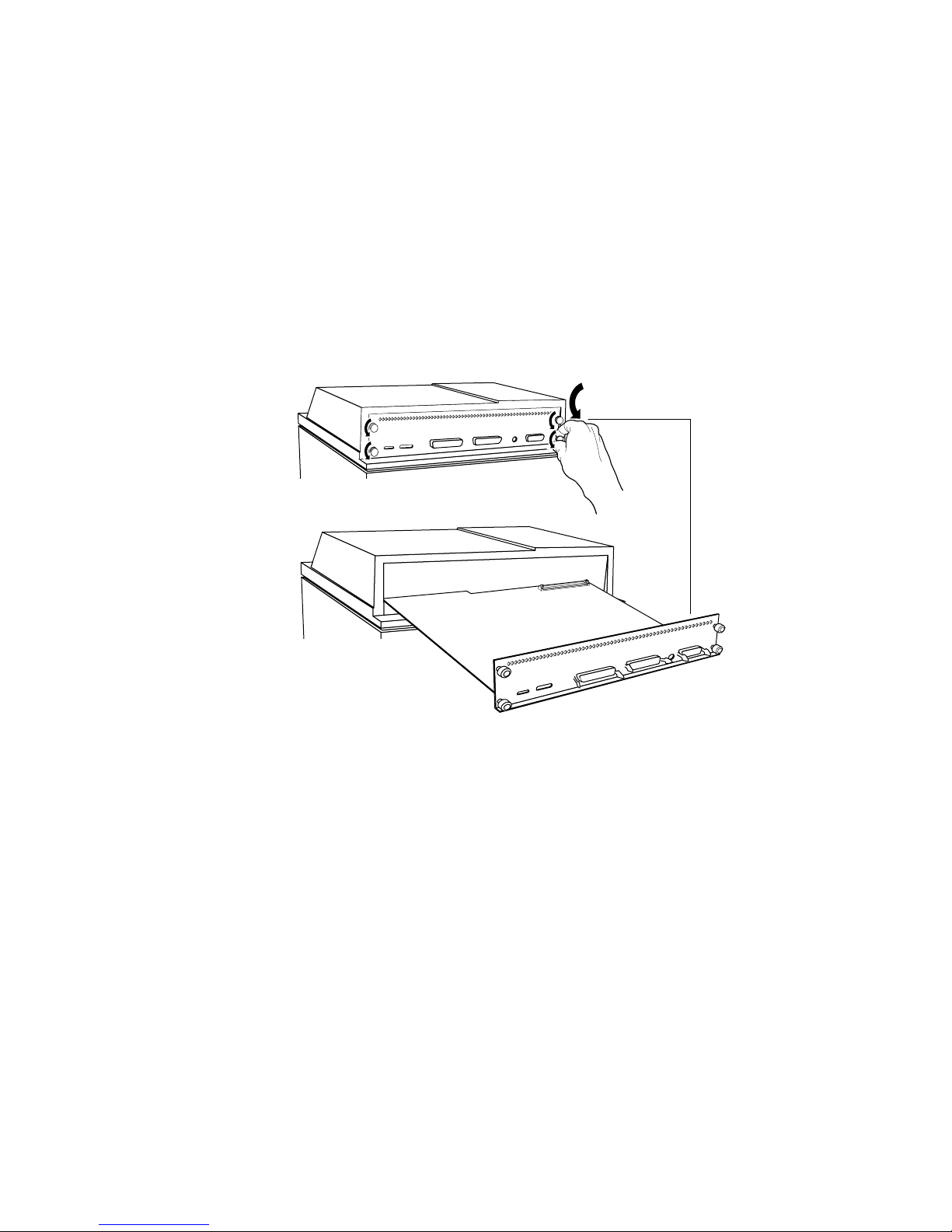
1.
Power down the printer. Do not unplug the printer; this preserves a
ground path to dissipate static charges. Disconnect the host interface
cables.
2.
Unscrew the four thumbscrews securing the image processor board's
rear panel to the printer. Slide the image processor board out of the
printer.
2
6
Page 7
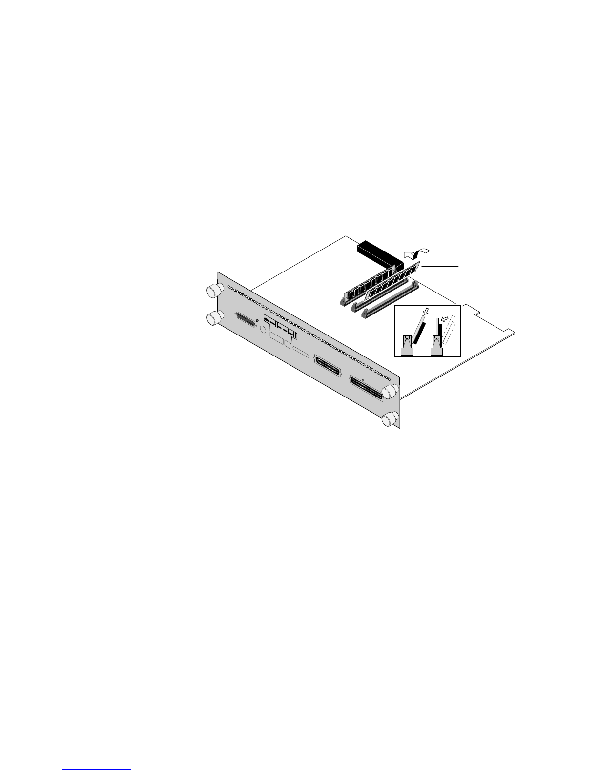
a
Locate the SIMM connectors:
3.
■
Labeled J160 on the PX image processor board
■
Labeled J6 on the PXi image processor board
4-Mbyte RAM SIMM Installation — (4690F4M)
PX image processor: Insert a memory module in connector J160 (
4.
and tilt the module upright until it locks in place (
b
).
ab
Note
For the PXi image processor: Install memory modules in the order J6
and then J7.
a
),
PXi image processor: Insert a memory module in connector J6 (or in
J7 if J6 is already filled) (
place
(b). Repeat Step 4 to install additional memory modules.
PHASER II PXi
MODEL 4694PXI
Serial
(RS-232)
12345 6 7
Reset
Extended
Run
AppleTalk
Diagnostics
Power Up
Input
®
Skip
Startjob
Run
Metric
Paper Size
American
Baud Rate
Variable
), and tilt the module upright until it locks in
J6
J7
J8
1200
89
Status
Parallel
SCSI Disk
ab
4
7
Page 8

4-Mbyte RAM SIMM Installation — (4690F4M)
When properly inserted, a tab on each end of the connector slips into a
hole on each end of the RAM SIMM. Also, a pawl on each end of the
connector latches around each end of the RAM SIMM to lock it
in place.
5.
Reinstall the image processor board in place and secure with the
thumbscrews.
Reconnect the host interface cables. Turn on the printer and make a
6.
print to ensure that the printer functions correctly.
8
Page 9

Phaser II PXe and Phaser II PXi
(bolt-down style image processor board)
1.
Power down the printer. Do not unplug the printer; this preserves a
ground path to dissipate static charges. Disconnect the host interface
cables.
2.
Remove the top panel. (Lift it carefully; the front panel LED cable is
still connected.)
Disconnect the front panel LED connector.
3.
4-Mbyte RAM SIMM Installation — (4690F4M)
2.
3.
2.
9
Page 10

4-Mbyte RAM SIMM Installation — (4690F4M)
Remove the two screws securing the front of the EMI shield. Tilt the
4.
shield up and remove it.
4
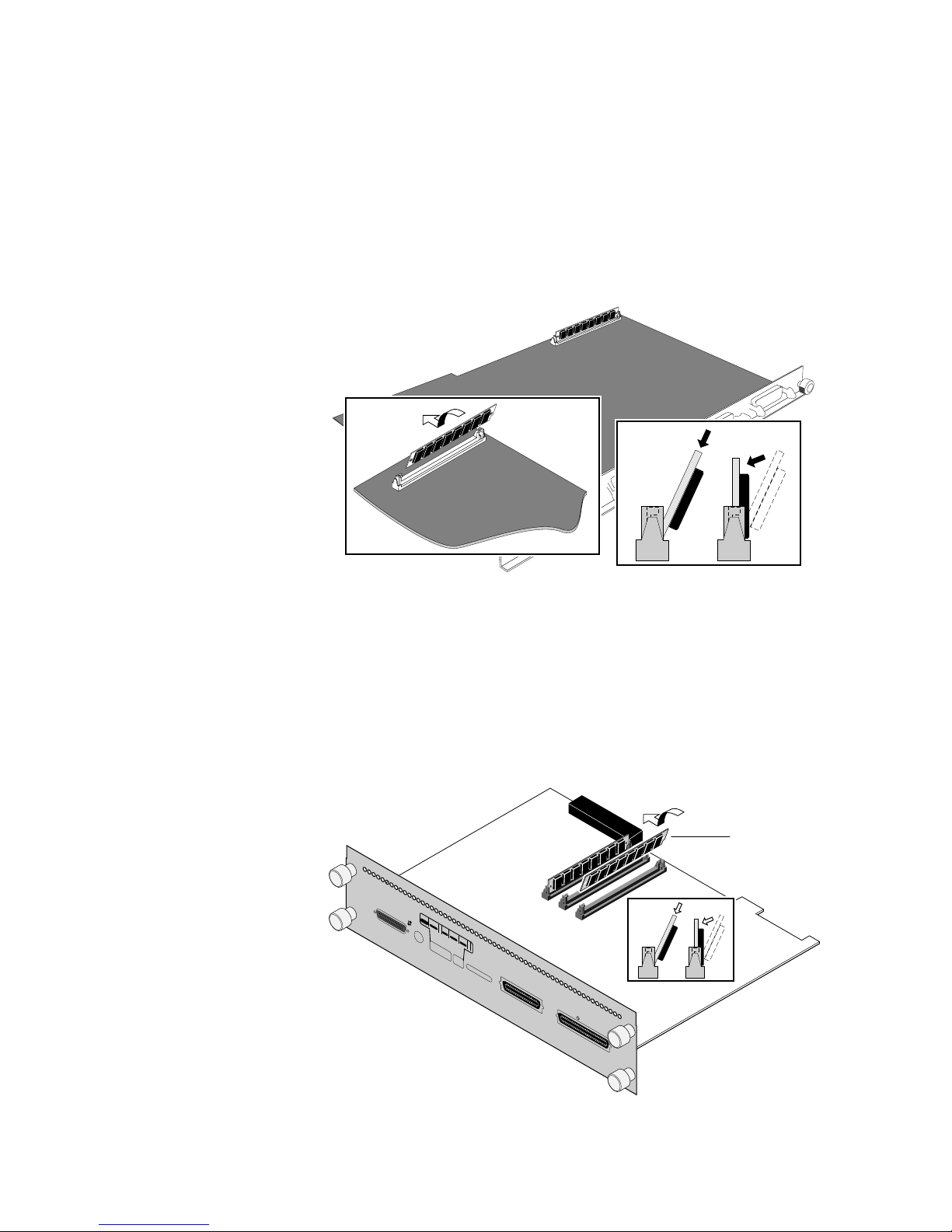
Locate the DRAM SIMM module connector J6.
5.
PXe image processor: Insert the DRAM SIMM in connector J6 (
6.
tilt the module upright until it locks in place (
a
6
b
J6
b
).
ab
8196-14
a
) and
8196-15
10
Page 11

4-Mbyte RAM SIMM Installation — (4690F4M)
When properly inserted, a tab on each end of the connector slips into a
hole on each end of the memory module. Also, a pawl on each end of
the connector latches around each end of the memory module to lock
it in place.
Note
For the PXi image processor: Install DRAM modules in the order J6
and then J7.
PXi image processor: Insert a DRAM SIMM in connector J6 (or in J7 if
J6 is already filled) (
place (
b
). Repeat Step 6 to install additional memory modules.
a
), and tilt the module upright until it locks in
ab
6
a
J7
b
J6
7.
8.
When properly inserted, a tab on each end of the connector slips into a
hole on each end of the memory module. Also, a pawl on each end of
the connector latches around each end of the memory module to lock
it in place.
Reinstall the EMI shield and the top panel. Reconnect the front panel
connector.
Reconnect the host interface cables. Turn on the printer and make a
test print to ensure that the printer functions correctly.
11
Page 12

4-Mbyte RAM SIMM Installation — (4690F4M)
Phaser III PXi
Phaser 300i
1.
Power down the printer. Do not unplug the printer; this preserves a
ground path to dissipate static charges. Disconnect the host interface
cables.
2.
Remove the two screws securing the image processor board in place.
Grasp underneath the rear panel and slide the image processor board
out of the printer card cage.
Do not pull on the connector bails.
12345
Reset
Extended
Run
Diagnostics
Power Up
Skip
Startjob
6
Run
Metric
Paper Size
American
Printers
B10XXXX
and
Phaser 300i
Printers
B01XXXX
to B06XXXX
12345
Reset
Extended
Run
Diagnostics
Power Up
Skip
Startjob
Run
Metric
Paper Size
American
7
1200
Baud Rate
89
Variable
Status
AppleTalk
Input
®
Serial
(RS-232)
6
7
1200
Baud Rate
89
Variable
Status
AppleTalk
Input
®
Serial
(RS-232)
PXi
Parallel
PXi
Parallel
SCSI Disk
SCSI Disk
8345-35A
12
Page 13

4-Mbyte RAM SIMM Installation — (4690F4M)
Note
For Phaser III printers serial numbered B01xxxx to B06xxxx:
Install memory modules in the order J7 and then J8. J6 should already
be filled.
3.
Insert a memory module in connector J7 (
upright until it locks in place (
module in J8.
1
Reset
2
Extended
3
Diagnostics
4
Power UpRun
5
Skip
Startjob
6
Run
Metric
Paper Size
American
7
1200
Baud Rate
89
Variable
Status
AppleTalk
Input
®
Serial
(RS-232)
PXi
J6
J7
Parallel
a
), and tilt the module
b
). Repeat to install additional memory
J8
ab
SCSI Disk
8345-36
13
Page 14

4-Mbyte RAM SIMM Installation — (4690F4M)
Note
For Phaser III printers serial numbered B10xxxx and higher and
Phaser 300i printers:
Install memory modules in the order J8 and
then J7. J9 should already be filled.
Insert a memory module in connector J8, or in J7 if J8 is filled (
tilt the module down until it locks in place (
1
Reset
2
3
Extended
Run
Diagnostics
4
Power Up
5
*
Skip
Startjob
6
Run
Metric
Paper Size
American
7
1200
Baud Rate
8
Variable
Blue Press
9
Color Adjust
Off Off
Status
LocalTalk®
Serial
(RS-232)
PXi
a
Parallel
SCSI Disk
b
Not Installed
Ethernet®
b
).
Insert SIMM
b
J9
J8
J7
a
), and
a
Repeat Step 3 to install additional memory modules.
4.
When properly inserted, a tab on each end of the connector slips into a
hole on each end of the RAM SIMM. Also, a pawl on each end of the
connector latches around each end of the RAM SIMM to lock it in
place.
5.
Reinstall the board in place and secure with the two screws.
Reconnect the host interface cables. Turn on the printer and make a
6.
print to ensure the printer functions correctly.
8345-94
14
Page 15

Phaser II SX/DX
(slide-in style image processor board)
1.
Turn the printer off. Do not unplug the printer; this preserves a
ground path to dissipate static charges. Disconnect the host interface
cables.
2.
Loosen the rear panel thumbscrews.
1
4-Mbyte RAM SIMM Installation — (4690F4M)
2
31113-9
3.
If just the image processor board is installed, then slide the image
processor board out of the printer. If the printer is equipped with a
multiplexer, then slide both the image processor board and the
attached 3-port multiplexer out of the printer.
Lay the image processor board (and the multiplexer, if attached) on a
4.
flat, static-free surface.
5.
Locate the connectors labeled SIMM #1, #2, and #3 on the image
processor board. (For the Phaser II DX printer, a memory module is
already installed in connector SIMM #1.)
5
SIMM
#1
#2
#3
3
4
Note
31113-10
Install memory modules in the order #1, then #2, and then #3.
15
Page 16

4-Mbyte RAM SIMM Installation — (4690F4M)
6.
Insert a memory module in connector SIMM #1 (or in SIMM #2 if
SIMM #1 is already filled) (a), and tilt the module upright until it locks
in place (b).
7.
Repeat Step 6 to install an additional memory module.
6b
6a
7
#1
#2
#3
31113-11
8.
Slide the 3-port multiplexer board, if the printer is furnished with one,
into the top slot. Slide the image processor board into the bottom slot.
Push and turn the thumbscrews to secure the board(s) in place.
8
9.
Reconnect the host interface cables. Turn the printer on and make a
test print to ensure that the printer prints correctly.
16
Page 17

4-Mbyte RAM SIMM Installation — (4690F4M)
Phaser II SX/DX (bolt-down style image processor board)
1.
Power down the printer. Do not unplug the printer; this preserves a
ground path to dissipate static charges. Disconnect the host interface
cables.
2.
Remove the top panel. Three of the screws securing the top panel are
at the rear of the printer. Open the top cover to access the three other
screws located on the front underside of the top cover. (Be careful
lifting the cabinet top; the front panel cables are still attached.)
3.
Disconnect the front panel LED connector. For DX printers,
disconnect the front panel LCD connector.
2
LED
3
LCD
2
-
17
Page 18

4-Mbyte RAM SIMM Installation — (4690F4M)
4.
Remove the two screws securing the front of the EMI shield. Tilt the
shield up and remove it.
4
5.
Locate the connectors labeled SIMM #1, #2, and #3 on the image
processor board. (For the Phaser II DX printer, a memory module is
already installed in connector SIMM #1.)
Note
Install memory modules in the order #1, then #2, and then #3.
31113-13
18
Page 19

4-Mbyte RAM SIMM Installation — (4690F4M)
6.
Insert a memory module in connector SIMM #1 (or in SIMM #2 if
SIMM #1 is already filled) (a), and tilt the module upright until it locks
in place (b).
#3
#1
#2
a
b
J3
J2
J1
ba
6
When properly inserted, a tab on each end of the connector slips into a
hole on each end of the SIMM. Also, a pawl on each end of the
connector latches around each end of the SIMM to lock it in place.
7.
Repeat Step 6 to install an additional memory module.
8.
Reinstall the EMI shield and the top panel. Reconnect the host
interface cables. Turn on the printer and make a test print to ensure
that the printer functions correctly.
31113-14
19
Page 20

4-Mbyte RAM SIMM Installation — (4690F4M)
Phaser IISD/SDX
1.
Power down the printer. Do not unplug the printer; this preserves a
ground path to dissipate static charges.
2.
Remove the cabinet top. (Be careful lifting the cabinet top, the front
panel LED cable is still attached.)
3.
Disconnect the front panel LED connector.
2.
3.
2.
20
Page 21

4-Mbyte RAM SIMM Installation — (4690F4M)
4.
Remove the two screws securing the front of the EMI shield. Tilt the
shield up and remove it.
4
5.
Locate the DRAM SIMM module connector J6.
6.
Insert a keyed DRAM SIMM in connector J6 (or in J7 if J6 is already
filled, or in J8 if J6 and J7 are already filled) (a), and tilt the module
upright until it locks in place (b). Repeat Step 6 to install additional
memory modules.
Note
Install memory modules in the order J6, J7 and then J8.
When properly inserted, a tab on each end of the connector slips into a
hole on each end of the memory module. Also, a pawl on each end of
the connector latches around each end of the memory module to lock
it in place.
Note
The SD/SDX image processor accepts both 4-Mbyte and
16-Mbyte SIMMs. A single 4-Mbyte SIMM can be mixed with
16-Mbyte SIMMs only if the 4-Mbyte SIMM is the last SIMM
installed. Install options:
31113-13
J6 J7 J8
4 Mbyte empty empty
16 Mbyte empty empty
16 Mbyte 16 Mbyte empty
16 Mbyte 16 Mbyte 16 Mbyte
16 Mbyte 4 Mbyte empty
16 Mbyte 16 Mbyte 4 Mbyte
21
Page 22

4-Mbyte RAM SIMM Installation — (4690F4M)
a
6
a
J8
J7
J6
7.
Reinstall the EMI shield. Reconnect the front panel connector.
b
Reconnect the cabinet top.
8.
Turn on the printer and make a print to ensure that the printer
functions correctly.
b
22
Page 23

Phaser 200i and Phaser 200e
1.
Power down the printer. Leave the power cord plugged in to provide
a ground path for static. Remove the interface cables.
2.
Remove the top-rear and rear cabinet panels.
3.
Remove the screws securing the I/O board to the card cage.
4.
Disconnect the I/O board ribbon cable(s) from the image processor
board. The Phaser 200i's I/O board has two ribbon cables; the Phaser
200e's I/O board has one ribbon cable. Remove the I/O board.
Phaser 200i
I/O board
4-Mbyte RAM SIMM Installation — (4690F4M)
Phaser 200e
I/O board
43
43
31442-02A
23
Page 24

4-Mbyte RAM SIMM Installation — (4690F4M)
5.
Remove the card cage top (3 screws).
6.
Move over the hinged card cage top.
7.
Lift out the image processor board.
5
7
6
24
Page 25

4-Mbyte RAM SIMM Installation — (4690F4M)
8.
Phaser 200e: Insert a memory module in connector J6 (a), and tilt the
module upright until it locks in place (b).
When properly inserted, a tab on each end of the connector slips into a
hole on each end of the RAM SIMM. Also, a pawl on each end of the
connector latches around each end of the RAM SIMM to lock it in
place.
RAM
SIMMs
ab
b
a
J6
J7
Phaser 200i: Insert a memory module in connector J6 (or in J7 if J6 is
already filled) (a), and tilt the module upright until it locks in place
(b).
When properly inserted, a tab on each end of the connector slips into a
hole on each end of the RAM SIMM. Also, a pawl on each end of the
connector latches around each end of the RAM SIMM to lock it in
place.
9.
Phaser 200i only. Repeat Step 8 to install an additional memory
module in J7 if a second SIMM is available.
10.
Reinstall the image processor board in the card cage.
11.
Reinstall the I/O board.
12.
Close and secure the card cage top. Reinstall the rear cabinet panels.
8699-65
13.
Reconnect the host interface cables. Turn on the printer and make a
print to verify that the printer functions correctly.
25
 Loading...