

Xerox Phaser Color 8400, Phaser Color 8500, Phaser Color 8550, Phaser Color 8560 Service Manual
Page 1

Версия 22.05.2009
Руководство по техническому
обслуживанию
PHASER 8400/8500/8550/8560
Документация изменена и дополнена:
1. Добавлены технические бюллетени для аппаратов Phaser 8400/8500/8550/8560.
Page 2
Xerox
Office
Group
Service Bulletin
2-Feb-2004
Phaser 8400
SB 607
Washer On The Drum Assembly’s Lower Right
Mounting Screw May Cause Dog-earing On Prints
Phaser Xerox Office Group Service Bulletin SB 607
2. Retighten the rear screw to 25 in-lbs.
3. Tighten the lower screw (without washer) and torque to 25 inlbs.
4. Tighten the front screw to 25 in-lbs.
When troubleshooting a persistent dog-ear print problem, ensure
the Stripper Carriage Assembly works correctly and the stripper
blade is not damaged. Also ensure an appropriate paper is being
used.
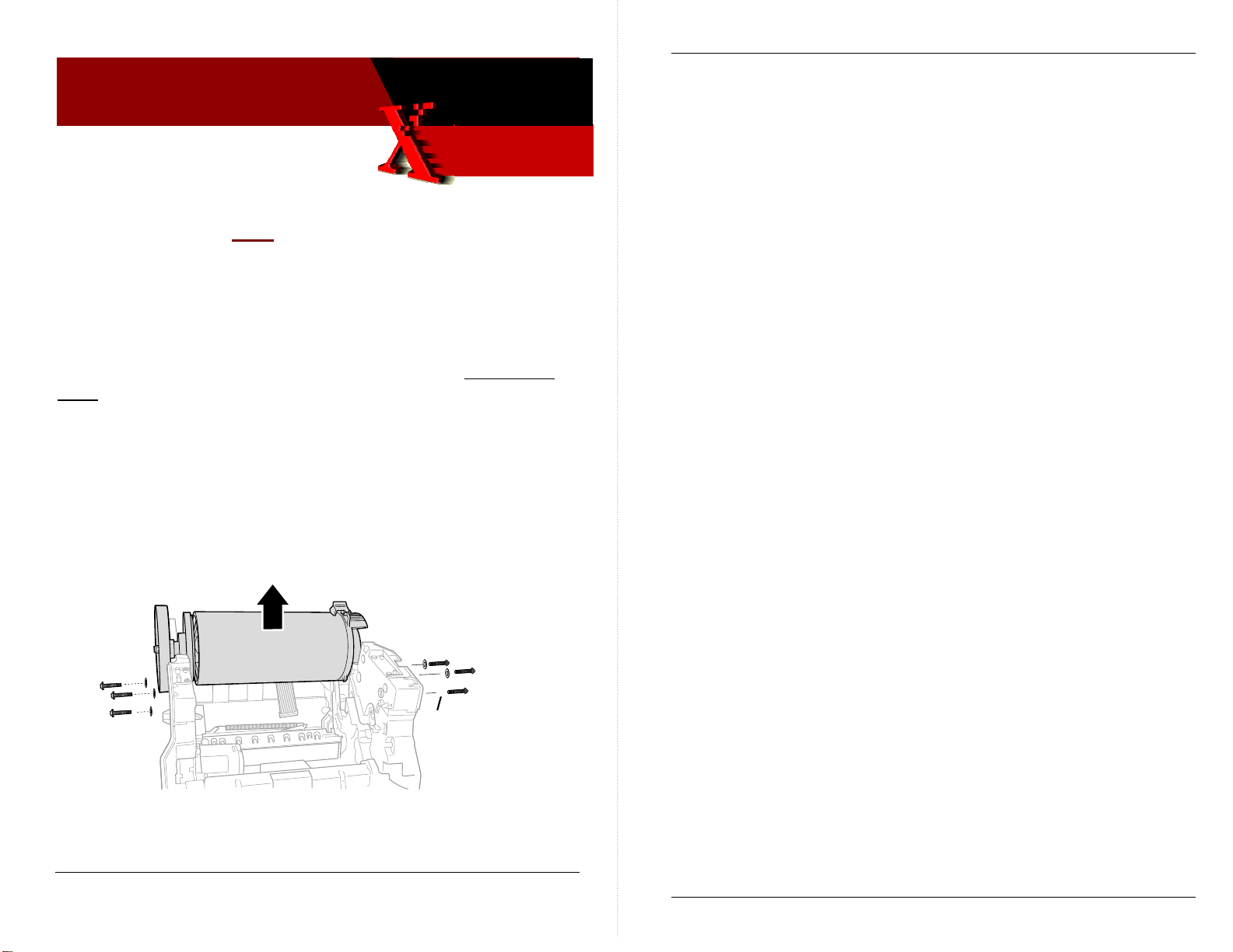
LOWER RIGHT DRUM SCREW USES NO WASHER
A washer added to the lower right screw that holds the Drum
Assembly to the Chassis on the right side prevents the right
Labyrinth Seal from seating in its proper location. This can cause
the Stripper Carriage to also not be properly located. In very rare
cases this results in prints on lighter-weight papers having one
corner folded over on the leading edge (dog-ear) as they are
stripped from the Drum. Occasional dog-earing is normal.
WHAT TO DO
When servicing a drum assembly ensure there is no washer on the
lower right drum mounting screw. Update your service manual’s
Drum Disassembly/Assembly Procedure indicating all the drummounting screws use washers except the lower right screw.
No washer
PARTS STRATEGY
Do not replace the Drum Assembly to correct a dog-ear print
problem. Remount the assembly and ensure the screws are
correctly installed and tightened.
TE
s8400-160a
The proper sequence for tightening the right-side drum screws is:
1. Loosen the three drum screws.
Service Manual Update SB607 SB 607 Error! Reference source not found. SB 607 Page 1 of 2
Copyright © 2003 Xerox Corporation. All rights reserved. XEROX®, the stylized X®, and Phaser®
trademarks of Xerox Corpo rati on i n the Unit e d States an d/o r oth er c ou ntri es.
Page 2 of 2
Page 3
Xerox
Office
Group
Service Bulletin
16-Aug-2004
Phaser 8400 SB608Rev1 Sb 608 Rev 1
SB 608, Rev 1
Some FRU part numbers are not orderable
SERVICE MANUAL LISTS FRU PART NUMBERS THAT
CANNOT BE ORDERED BY THE FIELD ORGANIZATION
Four part numbers listed in the service manual cannot be ordered by
the field organization. Alternate 650- part numbers have been set
up to use instead.
FRU Part Old (unusable)
part number
525-Sheet Feeder
(HCF) with Tray
Main Tray 097S03195 650-4332-00
097S03174 650-4331-00
New part number you
should order with
Hard Drive Assy 097S03172 650-4299-00
Hard Drive Assy with
Japanese Fonts
097S03173 650-4330-00
WHAT TO DO
Update your service manual with the new, replacement part
numbers. Do not use the old part numbers to order an FRU.
PART INVENTORY STRATEGY
Do not stock these parts. Order them only when needed for a
printer repair.
TME
Service Manual Update Error! Reference source not found. SB 608, Rev 1 Page 1 of 1
Copyright © 2003 Xerox Corporation. All rights reserved. XEROX®, the stylized X®, and Phaser®
trademarks of Xerox Corporation in the United States and/or other countries.
Page 4
Xerox
Office
Group
Service Bulletin
6-August-2004
Phaser 8400 SB624Rev2 SB 624 Rev3
SB 624 Rev 2
Printhead Exhibits Random Missing Jets
INFORMATION: SERIAL-NUMBERED PRINTERS RPC030017 TO
RPC044425 REQUIRE PRINTHEAD FIRMWARE CODE UPDATE
Printhead engineering has developed new drift compensation alg orithms
that improve reliability of the Phaser 8400 printer’s printhead. All printers
serial-numbered below RPC044426 need to have their printhead’s firmware
updated via a downloadable snippet file. Printers RPC044426 and above
already have the new algorithm built in.
The snippet file and a readme file are packaged as files 8400_fw_update.exe
(PC) or 8400_fw_update.dmg (Mac). They are available at:
http://www.office.xerox.com/cgi-bin/formeng.pl?form=8400printheadfirmware
Follow the readme instructions to download the snippet to a printer.
About a year or so after the printer was manufactured, a printhead that is
not updated will exhibit numerous, random missing jets. The missing jets
may clear with a cleaning cycle but other jets drop out. Downloadi ng the
update file to the printer resolves this problem. There is no means to
determine the printhead’s firmware version. Only downloading the snippet
to the printer will tell you if the printhead firmware is up-to-date or not.
Following the download, the printer prints a download status print.
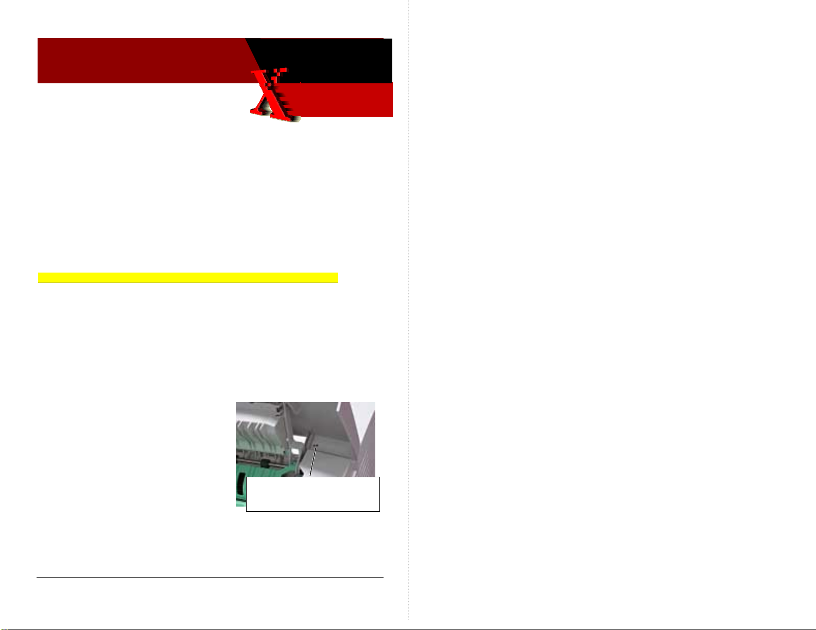
WHAT TO DO
As you service a Phaser 8400 printer,
check its serial number. If it is between
RPC030017 to RPC044425, download the
printhead firmware update snippet to
the printer. For update tracking
purposes, indicate in your Tech Notes
when you have updated a printer. Also
mark the underside of the exit door with
a “PH” to indicate the printer has been updated.
With an indelible marker,
mark the underside of the exit
door with a “PH”
PART INVENTORY STRATEGY
None. TME
Firmware Issue Page 1 of 1
Copyright © 2003 Xerox Corporation. All rights reserved. XEROX®, the stylized X®, and Phaser®
trademarks of Xerox Corpo rati on i n the Unit e d States an d/o r oth er c ou ntri es.
Page 5
Xerox
Office
Group
Phaser 8400
Service Bulletin
21-July-2004
SB 633
Phaser Xerox Office Group Service Bulletin SB 633
WHAT TO DO
Ensure these EMI countermeasures are correctly re-installed when
you service printers featuring these parts.
Older printers that do not feature these EMI countermeasures do
not need to be updated.
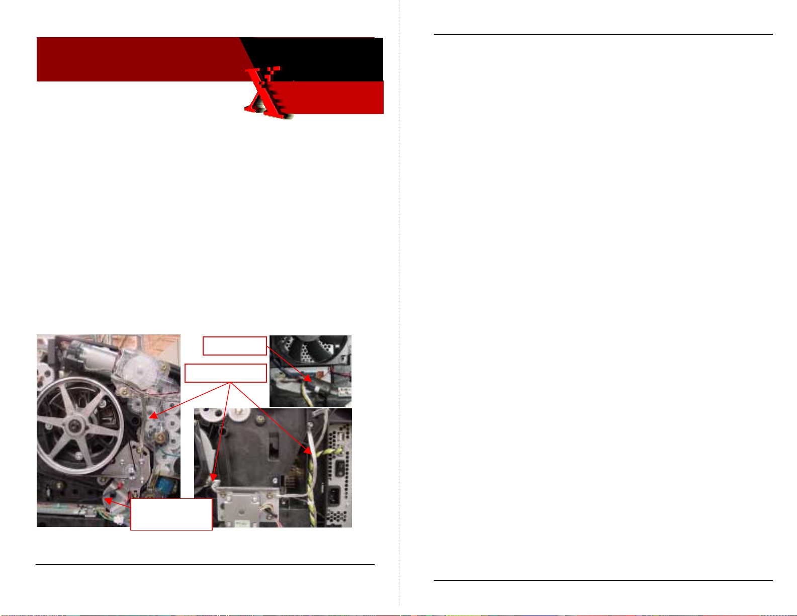
EMI Suppression Changes SB633 633
NEWER PRINTERS FEATURE NEW EMI SUPPRESSION
DEVICES
Newer printers may include new EMI countermeasures. These
include:
• Choke coil on the left umbilical wiring harness
• Media path motor-to-drum motor bracket ground strap
• X-axis motor bracket-to-drum fan bracket ground strap
• X-axis motor bracket-to-chassis ground strap
• 0-ohm Y-axis motor ground wire (replaces 100k ohm ground
wire)
Choke coil
Braided cables
Update your service manual with this information.
PART INVENTORY STRATEGY
None
TME
O-ohm ground
wire
Service Manual Update Error! Reference source not found. SB 633 Page 1 of 2
Copyright © 2003 Xerox Corporation. All rights reserved. XEROX®, the stylized X®, and Phaser®
trademarks of Xerox Corpo rati on i n the Unit e d States an d/o r oth er c ou ntri es.
Page 2 of 2
Page 6

Date Issued: 10 Oct 2006
SB 634 Rev 1
Product: Phaser 8400, 8500, 8550, C2424
Operational Groups: OPB, NADC
INSUFFICIENT AC POWER CAN CAUSE 37,002 THRU 37,013
PEST FAULT CODES
AC power supplied by power sources such as uninterruptible power
supplies (UPSs) or DC-to-AC inverter systems may not supply correct
voltage to properly power up the printer. Likewise, other devices
sharing the same AC circuit can cause AC voltage sags that cause the
printer to fail its AC heater PEST tests (Print Engine Self Test).
In both cases the printer may produce any of the following disconnected
heater errors:
• Printhead jet-stack 37,002.47 or 37,003.48
• Reservoir heater, 37,004.40 or 37,005.41
• Drum heater error 37,006.42
• Preheater error 37,008.44
• Ink melters errors 37,009.45 thru 37,013.40
SOLUTION
Verify the AC power source when you troubleshoot a printer exhibiting
any of these errors. Try powering up the printer on a different AC circuit
on a different breaker. Turn off other devices, such as laser printers and
coffee makers on the same circuit.
PART INVENTORY STRATEGY
None.
TME
Pub. No.:
CAUSE
The printer features several heaters controlled by printer electronics and
powered by AC electricity. The printer itself can power up despite
insufficient or irregular AC voltage but it may fail its AC heater tests.
This is due the test not measuring sufficient current flowing through the
heater at the moment the test runs.
Devices sharing the AC circuit shared with the printer, such as a laser
printer pulse-heating its fuser, a coffee maker heating its warming plate
via a thermo-breaker, or a space heater turning on, may be placing heavy
intermittent demand on the AC circuit. This sudden inductive demand
creates momentary AC voltage sag that causes the PEST test to fail.
Copyright © 2006 Xerox Corporation. All rights reserved. XEROX®, the stylized X®, and Phaser®
trademarks of Xerox Corporation in the United States and/or other countries.
1 of 1
Page 7
Xerox
Office
Group
Phaser 8400
Service Bulletin
21-July-2004
SB 635
SB635 635
Undocumented Error Codes 11,001 thru 11,100
UNDOCUMENTED/CORRECTED ERROR CODES
11,001.47 -
ECM_UHCF_SER_LINK_
BROKEN
11,002.41 -
ECM_LHCF_SER_LINK_
BROKEN
11,003.42 -
ECM_FP_SER_LINK_
BROKEN
11,004.43 -
ECM_IO_SER_LINK_
BROKEN
11,005.44 -
ECM_PCTL_SER_LINK_
BROKEN
11,006.45 -
ECM_HEAD_SER_LINK_
BROKEN
11,007.44 ECM_PCI_ERROR
11,008.45 -
ECM_DMA_TRANSFER_
FAILURE
11,009.46 -
Service Manual Update Error! Reference source not found. SB 635 Page 1 of 2
Copyright © 2003 Xerox Corporation. All rights reserved. XEROX®, the stylized X®, and Phaser®
trademarks of Xerox Corpo rati on i n the Unit e d States an d/o r oth er c ou ntri es.
Upper feeder –Tray 2 – broken serial communication timeout
failure detected. Seven consecutive frames occurred with
errors. Ensure the ground integrity of the printer. Inspect
and reseat all connectors. Reset NVRAM and retest.
Lower feeder –Tray 3 – broken serial communication timeout
failure detected. Seven consecutive frames occurred with
errors. Ensure the ground integrity of the printer. Inspect
and reseat all connectors. Reset NVRAM and retest.
Replace the Tray 3 feeder assembly.
Front panel broken serial communication timeout failure
detected. Seven consecutive frames occurred with errors.
Ensure the ground integrity of the printer. Inspect and reseat
all connectors. Reset NVRAM and retest. Replace the front
panel.
I/O board broken serial communication timeout failure
detected. Seven consecutive frames occurred with errors.
Ensure the ground integrity of the printer. Inspect and reseat
all connectors. Reset NVRAM and retest. Replace the I/O
board.
Power control board broken serial communication timeout
failure detected. Seven consecutive frames occurred with
errors. Ensure the ground integrity of the printer. Inspect
and reseat all connectors. Reset NVRAM and retest.
Replace the electronics module.
Printhead broken serial communication timeout failure
detected. Seven consecutive frames occurred with errors.
Ensure the ground integrity of the printer. Inspect and reseat
all connectors. Reset NVRAM and retest. Replace the
printhead
A PCI anomaly or PCI core bit error occurred. Ensure the
ground integrity of the printer. Inspect and reseat all
connectors. Reset NVRAM and retest. Replace the
electronics module
A DMA transfer error was detected. Ensure the ground
integrity of the printer. Inspect and reseat all connectors.
Reset NVRAM and retest. Replace the electronics module.
PostScript communication timeout failure detected. This
indicates the PS microcontroller received no response for
Phaser Xerox Office Group Service Bulletin SB 635
ECM_PS_COM_FAILURE 800ms. Ensure the ground integrity of the printer. Inspect
11,010.48 -
ECM_PS_HW_VERSION_
MISMATCH
11,011.48 -
ECM_PS_SW_VERSION_
MISMATCH
11,010.47 -
ECM_PS_HW_VERSION_
MISMATCH
11,012.49 -
ECM_PCTL_PLD_
VERSION_MISMATCH
11,013.41 -
ECM_IO_PLD_VERSION_
MISMATCH
11,014.42 -
ECM_FP_PLD_VERSION
MISMATCH
11,015.43 -
ECM_HEAD_PLD_
VERSION_MISMATCH
11,016.44 -
ECM_BTM_HCF_PLD_
VERSION_MISMATCH
11,017.45 -
ECM_TOP_HCF_PLD_
VERSION_MISMATCH
11,018.46 -
ECM_TITAN_VERSION_
MISMATCH
11,100.60 -
ECM: PS UC FOUND A
PARITY ERROR WITH
THE LAST ECM XMIT
and reseat all connectors. Reset NVRAM and retest.
Replace the electronics module.
PS hardware version mismatch. This indicates that the PS
hardware does not match the expected version. Replace the
electronics module.
PS software version mismatch. This indicates that the PS
software does not match the expected version. Replace the
electronics module.
PS hardware version mismatch. This indicates that the
PostScript hardware does not match the expected version.
Replace the electronics module.
Power Control PLD version mismatch. This indicates that the
power control programmable logic device does not match the
expected version. Replace the electronics module.
I/O PLD version mismatch. This indicates that the I/O
programmable logic device does not match the expected
version. Replace the I/O board.
Front panel version mismatch. This indicates that the front
panel programmable logic device does not match the
expected version. Replace the front panel.
Head PLD version mismatch. This indicates that the Head
programmable logic device does not match the expected
version. Replace the printhead.
Bottom HCF programmable logic device version mismatch.
This indicates that the bottom HCF programmable logic
device does not match the expected version. Replace the
Tray 3 feeder assembly.
Top HCF PLD version mismatch. This indicates that the top
HCF programmable logic device does not match the
expected version. Replace the Tray 2 feeder assembly
Titan version mismatch. This indicates that Titan chip does
not match the expected version. Replace the electronics
module.
Generally, the root problem for this error is temperature
sensitivity with the power-supply’s opto-isolat or chi ps.
Replace the electronics module.
WHAT TO DO
Update your service manual with this information.
PART INVENTORY STRATEGY
None
TME
Page 2 of 2
Page 8
Xerox
Office
Group
Phaser 8400
Service Bulletin
27-July-2004
SB 636
Troubleshooting the 37,016 Error Code SB636 636
TECHNIQUES FOR TROUBLESHOOTING THE 50V POWER
SUPPLY FAULT ERROR CODE
37,016.4x - PEST_FAULT_HM_CLUTCH_DISCONNECT
Despite the “clutch disconnect” message, thi s error code indicates that the
50V power supply failed its PEST test. (The 5 0V supply is loaded with the
head maintenance wipe r clutch in order to test; hence the message when
the test fails.) Follow these steps in the order listed to find a short that is
causing the 50v supply to fail:
1. Checking for a short in electronics module. Turn off the printer and
wait 30 seconds for power supply capacitors to
circuits within the electronics module may occur if the
capacitors are not allowed to fully discharge.
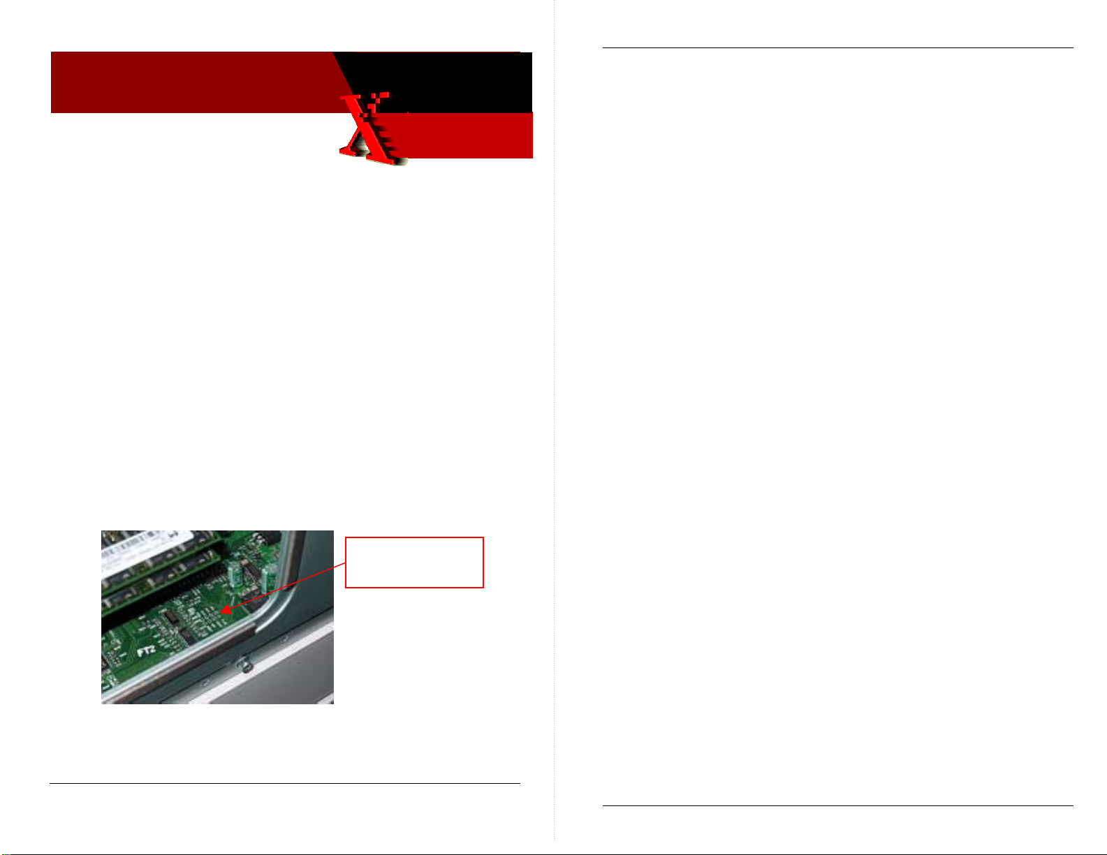
NOTE: It is possible that the power supply is not shorted but instead is
out of spec, which lead s to an error conditio n. You can measure the
50V power supply output. The test point is located o n the Power
Control board below the main board’s RAM DIMMs.
discharge. Damage to
power supply
50v power supply
test point
Phaser 8400 Xerox Office Group Service Bulletin SB 636
2. Unplug the following electronics module connectors. This step
disconnects all other ex ternal circuits so the e lectronics module c an be
tested alone:
• Power Control to I/O board (J800 - gray ribbon cable on right side)
• Power Control right (J400 – 16 wire, multi-color)
• Printhead data interface (J130 – gray ribbon cable on top side)
• Wave amp signal (J790) short gray ribbon cable located on left side)
• Power Control left (J390 – 34 wire, multi-color)
• Y-Axis motor (J280)
3.
Turn on power to the printer.
4. If the PE and PS indicators do not flash, the short is in side the
electronics module. Replace the electronics module and retest the
printer. If PE and PS indicators flash, continue with the next step.
5. Checking for short on the I/O board. Turn off the printer and wait 30
seconds for power supply capacitors to discharge.
6. Unplug the front panel connector (J220) on the I/O board. This
removes the front panel from the I/O board.
7. Plug in the Power Control to I/O board connector (J800). This step
adds the I/O board back to the working electronics module - nothing
else is connected.
8. Turn on power to the printer. If the PE and PS indicators do not flash,
the short is on the I/O board or related cabling.
If the 50V PS LED (viewed thru the cooling grill below the power cord
receptacle) illuminates, the short is on one of the external devices you
unplugged earlier. In this case, systematically tur n off the printer,
plug a wiring harness back in, and turn the printer on until the 50V
supply fails.
Typically, the power supply should measure 50v (47 to 52v).
Service Manual Update Error! Reference source not found. SB 636 Page 1 of 4
Copyright © 2003 Xerox Corporation. All rights reserved. XEROX®, the stylized X®, and Phaser®
trademarks of Xerox Corpo rati on i n the Unit e d States an d/o r oth er c ou ntri es.
9. Turn off the printer. Verify the short is on the I/O board by using an
ohmmeter to check the resistance on I/O board J270, pin 1 to ground.
Resistance of less than 1K ohm indicates a problem.
10. To isolate the problem to the I/O board or its related cabling, unplug
the I/O board connectors. Leave the control panel (J220) plugged in:
• Umbilical Right J1
• Waste Tray Sense J110
• Stripper Solenoid J250
• Paper Tray Sense J610
Page 2 of 4
Page 9

Phaser 8400 Xerox Office Group Service Bulletin SB 636
Phaser 8400 Xerox Office Group Service Bulletin SB 636
• Front Door Sense J600
• Ink load Signal J910
• DMU Sense J860
• Drum Thermistor J870
• Exit Module J680
• Heater Relay Control J950
11. Retest the resistance of the I/O board. If the resistance is still less than
1K ohm, replace the I/O board, reinstall all cables and retest printer.
If the I/O board resistance is not shorted, plug in the I/O board
connectors one at a time and retest the resistance. Replac e the
component that creates a short at J270.
12. Turn on the printer.
13. If the PE and PS indicators do not flash, the short is on the front panel.
Replace the front panel and retest the printer.
14. Checking for a short circuit on 50V within the printhead. Turn off
printer and wait 30 seconds for power supply capacitors to discharge.
15. Plug in the printhead interface connector (J130) to the electronics
module. This step adds the printhead back to a working electronics
module and I/O board.
16. Turn on power to the printer.
WHAT TO DO
Update your service manual with this information.
PART INVENTORY STRATEGY
None
TME
17. If the PE and PS indicators do not flash, the short is on the printhead.
Replace the printhead and retest the printer. Test the printer to ensure
damage to the electronics module did not occur due to the shorted
printhead.
18. Run the Head Maintenance Clutch test.
19. Check the Head Maintenance Clutch wiring.
20. Connect the Wave Amp signal cable (J790) at the left side of the
Electronics Module.
21. Turn on power to the printer. If the PE and PS indicators do not flash,
the short is on the wave amp. Replace the wave amp.
22. Reinstall all printer cables.
23. Test the printer.
Page 3 of 4
Page 4 of 4
Page 10

Xerox
Office
Group
Service Bulletin
3-Aug-2004
Phaser 8400
SB 637
Troubleshooting Dead or Hung Printers SB637 637
Phaser 8400 Xerox Office Group Service Bulletin SB 637
1. Turn off the printer. Wait for it to completely shut down. Unplug
the printer’s AC power cord.
2. After at least 30 se c onds, reconnect the power c or d and turn on the
printer.
• If the printer powers-up correctly, try printing the
Configuration Page or Startup Page (or any embedded page).
If the embedded pages print normally, the problem has been
solved.
Techniques For Troubleshooting Printers That Are Hung
At Power-Up Or Appear Dead
Dead or hung printers can fail to power-up for a variety of reasons
ranging from improper AC power source to defective components.
The following steps can help resolve dead or hung printers:
1. Verify the printer is in a hung conditi on
2. Eliminate corrupted data in the printer’s mem ory
3. Isolate the printer from the network
4. Isolate the hard drive (if installed )
5. Verify the power source
Verify The Printer Is Hung
The printer can take several minutes to reach its operating temperature.
Cold environments require more time. If the printer appears to be hung
(unable to respond), ope n the front cover.
• If the front panel message changes from “Warming Up ” to “Close
Front Cover to Continue”, the printer is not hung. Instead, it may
be in the process of warming up, canceling a large job, or even
processing a job.
• If the printer does not power-up correctly, go to the next
procedure.
Isolating Network Issues
Corrupted network traffic, print files, or printer drivers ca n cause the
printer to hang. Use the following procedure to isolate the printer from the
network:
1. Disconnect all communication cables from the printer, power
down the printer for 30 seconds, and then turn on t he printer.
• If the printer does power-up, try printing an embedded page
such as the Configuration page or Startup.
• If the embedded pages do not print, there may be
corrupted data in the printer’s RAM. Complete the
procedure “Eliminate Corrupted Data from RAM”.
• If the embedded pages print normally, go to Step 2.
• If the printer does not power-up correctly, proceed to the
“Isolate the Hard Drive” topic.
2. Try printing an embedded page when the printer is connected to
the network.
• If the embedded pages print normally, go to Step 3.
• If the front panel message does not change after opening the front
cover, the printer is hung (unable to respond).
Eliminate Corrupted Data From Memory
If there is corrupted data in the printer’s memory, the printer may be
unable to generate embedded pages. Use the following procedure to
eliminate the corrupted data:
Service Manual Update Error! Reference source not found. SB 637 Page 1 of 4
Copyright © 2003 Xerox Corporation. All rights reserved. XEROX®, the stylized X®, and Phaser®
trademarks of Xerox Corpo rati on i n the Unit e d States an d/o r oth er c ou ntri es.
• If the printer stops responding while connected to the network,
there may be corrupt network information getting to the
printer.
3. Send a print job to the printer using the network connection. If the
printer stops responding only after sendi ng the print job, the file or
printer driver may be corrupted. Try to isolate the file and/or
reinstall the printer driver. Reviewing the printer's Network Logs
(front panel Troubleshooting menu > Network Log Pa ges) can
offer clues to a network event that might be confusing the printer.
Page 2 of 4
Page 11

Phaser 8400 Xerox Office Group Service Bulletin SB 637
Phaser 8400 Xerox Office Group Service Bulletin SB 637
Isolate the Hard Drive (if installed)
If the printer is a DX model equipped with a hard drive, corrupted files on
the hard drive may prevent the printer from completing its start-up
sequence. Use the following procedure to isolate problems to the hard
drive. Observe ESD precautions:
1. Turn the printer off.
2. At the rear of the printer, open the access panel (held in place with
two thumbscrews). The hard drive mounts to the access panel.
3. Disconnect the wide, gray data cable from the Hard Drive
Assembly.
4. Turn on the printer.
• If the printer powers on normally, the hard drive must be
replaced.
• If the printer fails to power on go on to the next procedure.
Verify the Power Source
Verify the printer is plugged into a stable power so urce that can supply
enough current for the printer’s initial warm-up. Always plug the printer
directly into a known-to-be- good outlet. If other devices are plugged into
the same circuit, there may not be enough power available for the printer.
The printer can tolerate AC power level fluxuations (brown-outs) . But it
cannot tolerate loss of A C cycles (blips, interruptions) or AC fre que nc y
changes. Also, the printer power must be a standard sinewave waveform.
Note: Many DC-to-AC inverter systems, gas-powered AC generators, and
uninterruptible power supply devices do not output proper
sinewave-shaped AC power. This makes them unsuitable as power
sources for the printer. Likewise, many of those devices cannot
output the current necessary to power the printer.
If the printer is unable to power on, use the following procedure to verify
the power source:
1. Disconnect the printer from the suspect outlet.
2. Plug the printer directly into a stable, known- to-be-good wall
outlet. If possible, monitor the line voltage. For testing purposes,
do not use any of the following:
• Circuits that connect to several other devices.
If the power-up problem only occurs when the printer is plugged
into a surge protector, power strip, UPS, or one specific outlet, then
the problem is with that device or outlet.
3. Verify that both ends of the power cord are firmly plugged in.
4. Turn on the printer.
• If the printer powers on normally, the problem has been
solved.
• If the printer does not power on, go to Step 5.
5. Did the printer start power cycling (turning off and on) after a
power surge from an electr ical storm or power outage?
• If yes, turn the printer off and unplug it. After waiting at least
2 hours, plug the printer into a stable, known-to-be-good wall
outlet and turn it on.
• If no, complete the next procedures found in the printer
Service Manual.
6. Check for illuminated LEDs on the printer’s power supply. Refer
to Service Manual topic “Verifying Power Supply Operation” for
locations of the LEDs. Refer to Service Ma nua l topic "Printer Fails
to Power-Up: PS, PE and the 3.3 V Indicator LEDs are Not
Illuminated" for troubleshooting instructions.
WHAT TO DO
Update your service manual with this information.
PART INVENTORY STRATEGY
None
TME
• Power strip/surge protector
• Uninterruptible power supply (UPS)
Page 3 of 4
Page 4 of 4
Page 12

Xerox
Office
Group
Service Bulletin
Phaser 8400, 8200, 860, 850 SB640 SB 640
20-Aug-2004
SB 640
JetFix Snippets Available To
Correct Weak And Missing Jets SB640 640
DOWNLOADABLE SNIPPETS EFFECTIVE FOR CLEARING
WEAK OR MISSING PRINTHEAD JETS
A technique, referred to as JetFix, has been developed that is
effective in clearing stubborn weak or missing jets that a printer’s
regular printhead purge cycle cannot clear. The technique consists
of raising the printhead drive voltage to 255, printing several solid
fills of the missing jet color, returning the drive setting to its default
128 setting, and then performing a printhead clean/purge cycle.
The technique is effective about 50% of the time in clearing a
stubborn weak or missing jet.
This technique has been encapsulated into two sets of downloadable
snippet files to simplify performing the technique. One set of files is
for the Phaser 8400. The other set is for the 8200, 860 and 850. (The
technique is not very effective in the Phaser 840 because of the age
of the printheads).
Each set consists of four snippets; one for each ink color. When a
printer receives a JetFix snippet it will print five double-coverage
solid fills and then perform a printhead clean/purge cycle.
Note: It is normal for the solid-fill prints to show many light
stripes; this will clear with the purge cycle.
If process should be interrupted by a power glitch or a hang, powerdown the printer, wait 30 seconds, and turn on the printer. The 255
Head Adjust setting automatically will be overwritten by the 128
value retrieved from the printer’s NVRAM on power-up.
Phaser 850, 860, 8200, 8400 Xerox Office Group Service Bulletin SB 640
WHAT TO DO
Before replacing a printhead for a weak or missing jet issue (not
caused by non-Xerox ink) upload the appropriate JetFix snippet to
the printer. Use the snippet that corresponds to the jet’s missing
color. JetFix is effective in clearing printheads with one or two
missing jets that cannot be cleared using the printer’s “Eliminate
Light Stripes” cleaning cycles.
Obtain the snippets from the Customer Support Resources website:
http://www.office.xerox.com/partners
pulldown to retrieve the 8400’s snippets. Select 8200 or 860 from the
Printer Info pulldown for the 8200/860/850 snippets.
A readme file is included with instructions on different methods of
uploading a snippet to a printer.
Important Note: Always follow and complete the latest version of the
Troubleshooting Printhead Checklist. Be sure to
include sample prints as noted in the checklist. Also be
sure to correctly complete the green card.
. Select 8400 from the Printer Info
PART INVENTORY STRATEGY
None
TME
Information 20-Aug-2004 SB 640 Page 1 of 2
Copyright © 2004 Xerox Corporation. All rights reserved. XEROX®, the stylized X®, and Phaser®
trademarks of Xerox Corpo rati on i n the Unit e d States an d/o r oth er c ou ntri es.
Page 2 of 2
Page 13
Xerox
Office
Group
Service Bulletin
Phaser 8400, WorkCentre C2424,
Phaser 8500/8550
29 June 2005
SB 647 Rev 1
Camshafts Incorrectly Illustrated
In Service Manual
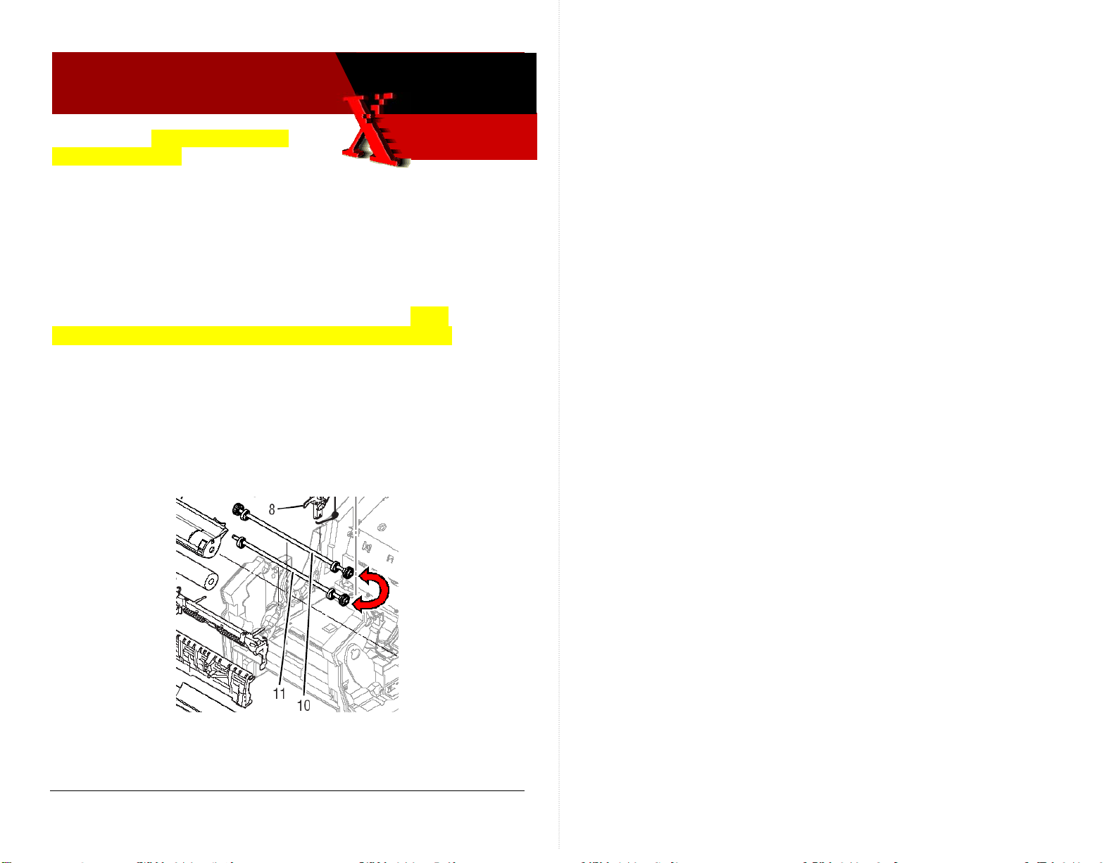
INFORMATION
The illustration on page 9-6 of the Service Manuals incorrectly
shows the Drum Maintenance Camshaft and Transfix Camshaft
assemblies. The camshaft drawings are transposed. Items
highlighted in yellow indicate updates to original bulletin.
WHAT TO DO
Item 11 should point to the Drum Maintenance Camshaft (which
has a gear at each end of the shaft). Item 10 should point to the
Transfix Camshaft (it has no gear on its left end). The Drum
Maintenance Camshaft should be located below the Transfix
Camshaft. Modify your Service Manual similar to the following
illustration.
PART INVENTORY STRATEGY
N/A JMK
Service Manual Update 29 June 200 SB Page 1 of 1
Copyright © 2004 Xerox Corporation. All rights reserved. XEROX®, the stylized X®, and Phaser®
trademarks of Xerox Corporation in the United States and/or other countries.
Page 14

Xerox
Office
Group
Service Bulletin
Phaser 8400 SB655 SB 655 sb655 sb 655
8-Dec 2004
SB 655
Paper Path Motor Cooling Fan deleted,
Left Side Power Control Harness and
Exit Module Assembly modified
INFORMATION
The Paper Path Motor Cooling Fan is no longer installed on printers
serial-numbered RCP148641 and above. The Left Side Power
Control Wiring Harness has been modified to remove the fan’s
receptacle and to include a resistor to simulate the presence of the
fan to the printer’s boot up firmware. The exit module assembly has
been modified to remove the motor cooling fan.
Ongoing reliability testing has determined that the motor cooling
fan is not necessary. Therefore it is being removed for the remaining
printers being built.
Phaser 8400 Xerox Office Group Service Bulletin SB 655
Service tips:
If a motor cooling fan has failed, remove it and replace the Left
Side Power Control Wiring Harness with the new -81 version
harness.
If you replace the exit module assembly, move the motor cooling
fan from the old exit module assembly to the new assembly.
If you replace an old Left Side Power Control Wiring Harness
(which does not have a paper path cooling fan plug receptacle),
remove the paper path motor cooling fan.
The printer will produce the power-on error code 37,015.42
FAULT MP MOTOR DISCONNECT if the printer boots up with
an old Left Side Power Control Wiring Harness but no Paper
Path Cooling Fan.
PART INVENTORY STRATEGY
Do not stock these parts. Order them only when needed for a
printer repair.
TME
WHAT TO DO
Update you service manual with these new part numbers:
Paper Path Motor Cooling Fan
Exit Module Assembly 441-2239-81
Cable, Power Control Left Side 174-4494-81
Parts Issue/Service Manual Update 8-Dec 2004 SB 655 Page 1 of 2
Copyright © 2004 Xerox Corporation. All rights reserved. XEROX®, the stylized X®, and Phaser®
trademarks of Xerox Corporation in the United States and/or other countries.
No longer available
Page 2 of 2
Page 15
D
Xerox
Office
Group
Phaser 8400
Service Bulletin
06 Sept 2005
SB 657 Rev 2
Ripping sound during transfixing; prints show
poor transfix print quality
PIVOT PLATES CRACKING RESULTS IN INSUFFICIENT
DRUM OILING
Cracking of the drum maintenance pivot plate results in the pivot
plate not pushing the drum maintenance unit forward enough to
provide sufficient oiling of the imaging drum during a print cycle.
The result is poor ink transfixing and poor print quality.
The pivot plate may crack at either the left end or the right end or
both. This results in a print quality defect, such as dropout or smear,
at the corresponding left or right sides of the prints.
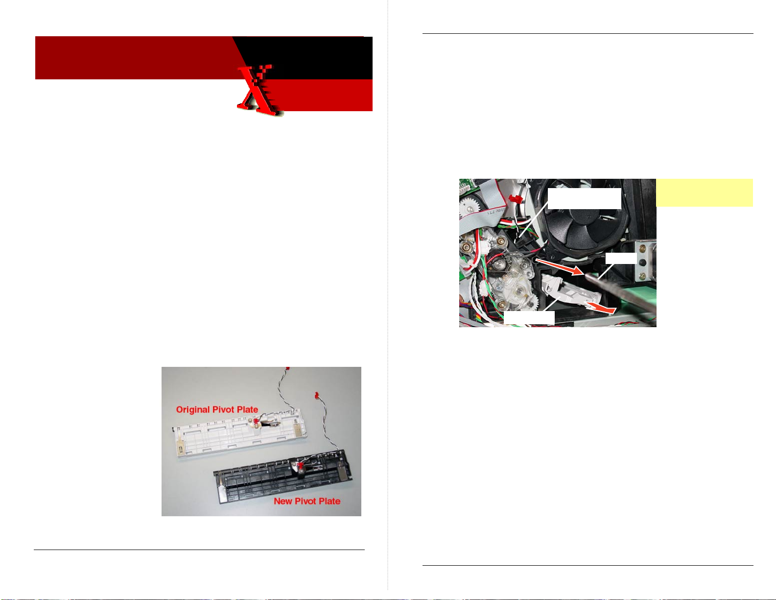
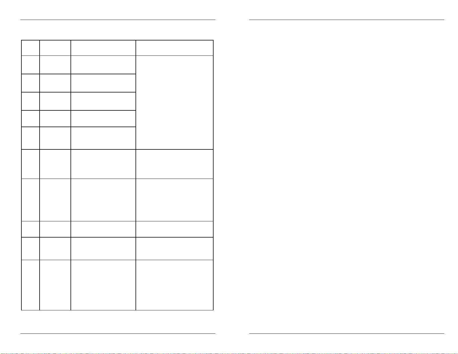
WHAT TO DO
Replace the
original (white)
pivot plate with
the new (black)
pivot plate.
Phaser 8400 Xerox Office Group Service Bulletin SB 657 Rev 2
To replace the pivot plate:
1. Power-down the printer.
2. Remove the drum maintenance kit.
3. Remove the left and right side covers.
4. Unplug the pivot plate wiring harness from I/O board J860.
5. Remove the ground clip (lower-left corner of drum fan) from
the right end of the drum maintenance shaft.
6. Remove the KL-clips securing each end of the drum
maintenance shaft. Slide the shaft out of the printer frame.
7. Remove the pivot plate thru the drum maintenance kit cavity.
Wiring harness
routes thru hole
Shaft
Pivot Plate
Observe standard ES
precautions
Lightly grease the metal plates on which the drum maintenance
cams ride, using a small amount of Rheolube 768 grease (P/N 0067997-00). Also fill the pocket under the shaft ground with grease.
Reverse the removal steps to install the new pivot plate.
Tip
It you have difficulty seating the left end of the shaft thru the left
side frame; remove the paper preheater for better access to the
left end of the shaft and the pivot plate. Use needle-nose pliers to
fish the wiring harness thru the right-side frame hole.
Hardware Issue SB 657 Rev 2 Page 1 of 2
Copyright © 2004 Xerox Corporation. All rights reserved. XEROX®, the stylized X®, and Phaser®
trademarks of Xerox Corporation in the United States and/or other countries.
PART INVENTORY STRATEGY
Order this part as needed, and keep no more than one in trunk
stock.
TME
Page 2 of 2
Page 16

)
Xerox
Office
Group
Service Bulletin
Phaser 8550/8500
21 Sept 2005
SB 700
Service Manual Corrections
INFORMATION
The tables below list errors, corrections and omissions in the
Phaser 8400/8500/8550 Service Manual.
Table 1 Replaceable Parts List Changes
Page
#
9-5 Drum Maintenance Door
9-6 Illustrations of items 10 and
9-7 Ink Loader Assy and Door
9-7 Printhead Wiper Assembly
9-7 Belt, Wiper Drive
9-7 Purge Pressure Pump
9-7 Transfix Camshaft Assy
9-7 Transfix Roller
9-7 Drum Maintenance Pivot
Service Manual Update SB Page 1 of 4
Copyright © 2004 Xerox Corporation. All rights reserved. XEROX®, the stylized X®, and Phaser®
trademarks of Xerox Corporation in the United States and/or other countries.
Item or Wording was: Correction or Change is:
Drum Maintenance Door (Side)
(Side) 802K93870
11 are swapped.
133K25030
8500/8550 require ver. 4.302
firmware
8500/8550 require ver. 4.302
firmware
604K31120
068K02160
401102780 (8400)
022E32280 (8500/8550)
Plate Assy 367053180
802E93870
Item 11has a gear on each end
of the camshaft. Item 10 only
has a gear on the right end
Ink Loader Assy and Door
133K25031 (8500/8550)
Ink Loader Assy and Door,
PagePack 133K25660 (8550M)
367053480 (8400/8500/8550)
033E05080 (8500/8550)
214501280 (8400/8500/8550)
023E30660 (8500/8550)
Purge Pressure Pump
119641180
Transfix Camshaft Assy
008K02160
Transfix Roller
401102780 (8400)
022E32290 (8400/8500/8550)
Drum Maintenance Pivot Plate
Assy 367053181
Phaser 8500-8550 Xerox Office Group Service Bulletin SB 700
9-9 Outer Duplex Paper Guide
with Sensors 351113681
9-9 525-Sheet Feeder and Tray
059K50030
9-11 Gearbox Media Drive with 2
Clutches 807K16050
9-13
9-13
9-15 Safety Interlock Switch (Mech
9-16 Mechanical Kit (Hardware)
9-16 Frame Replacement Screw
9-16 Repackaging Kit (8500/8550)
9-17 Memory (8500)
9-17 Memory (8550)
9-18
128 MB SDRAM 156486100
(8400)
256 MB SDRAM 156466300
(8400)
128 MB SDRAM 537E66480
(8500/8550)
256 MB SDRAM 537E66490
(8500/8550)
512 MB SDRAM 537E66500
(8500/8550)
Config Card-N 069E00360
(8500/8550)
Config Card-DN 069E00370
(8500/8550)
119645581
650429700
(silver tint)
695K22810
128 MB, SDRAM ZMD128
256 MB, SDRAM ZMD256
256 MB, SDRAM ZMD256
512 MB, SDRAM ZMD512
Not listed
not listed
Outer Duplex Paper Guide with
Sensors 351113680
525-Sheet Feeder and Tray
650-4331-00
Gearbox Media Drive with 2
Clutches 807E16050
128 MB SDRAM 156483700 (8400)
256 MB SDRAM 156466300 (8400)
128 MB SDRAM 856000200
(8500/8550)
256 MB SDRAM 856000300
(8500/8550)
512 MB SDRAM 856000400
/8550)
(8500
Config Card-N 069E00360
(8500/
8550)
Config Card-DN 069E00370
(8500/8550)
Safety Interlock Switch (Mech)
119645580
Mechanical Kit (Hardware)
604K31780
Frame Replacement Screw
(red tint)
Repackaging Kit (8500/8550)
659K22810
Memory (8500)
128 MB, SDRAM 097S03380
256 MB, SDRAM 097S03381
Memory (8500)
256 MB, SDRAM 097S03381
512 MB, SDRAM 097S03382
Metered Solid Ink Cyan
(6 sticks) 108R00706 (8550M)
Metered Solid Ink Magenta
(6 sticks) 108R00707 (8550M)
Metered Solid Ink Yellow
(6 sticks) 108R00708 (8550M)
Metered Solid Ink Black
(6 sticks) 108R00709 (8550M)
Rainbow Pack (1 each color)
108R00612 (8400)
058K00200 (8500/8550)
Page 2 of 4
Page 17
Phaser 8500-8550 Xerox Office Group Service Bulletin SB 700
Phaser 8500-8550 Xerox Office Group Service Bulletin SB 700
Table 2 Fault Codes Corrections and Updates
Page
#
3-10 2,008.67 Configuration Card is
2,009.68 Configuration Card is
2,010.69 Configuration Card is
2,011.61 Configuration Card is
2,012.62 Configuration Card is
3-14 5,004.44 Y-axis General
3-23 9,035.43
3-32 19,005.63 Wave Amp
3-32 26,962.64 “Fall out” code Check the previous error is
3-35 36,002.44 Printer can’t write to
Error
code
thru
9,038.46
Description Action
1. Turn off printer
missing.
bad.
blank.
for the wrong product.
an invalid model.
Failure
Ink Stick Count Fault The clear ISC Fault menu
overcurrent
Drum Maintenance
Unit
2. Verify that config card is
correct card for printer
3. Insert or replace config
card.
4. Turn on printer.
5. If problem continues,
replace the electronics
module.
There is a problem with the
Y-axis motion sub-system.
Troubleshoot the same as
for a 5,003.43 error code.
item is located in the
internal diagnostics
Functions Menu. This must
be performed following an
ink loader replacement.
This error can occur in toolow humidity conditions
the fault history and
troubleshoot that code.
1. Ensure the DMU seats
correctly in the pivot
plate.
2. Replace the DMU.
3. Replace the drum
maintenance pivot plate
assy.
WHAT TO DO
Note these corrections in the hard copy of your Service Manual.
PART INVENTORY STRATEGY
Not applicable.
TME
Page 3 of 4
Page 4 of 4
Page 18
Xerox
Office
Group
Service Bulletin
21 Sept 2005
Phaser 8500 8550
SB 701
Updated Firmware Code and Wiper Belts Now
Shipping with Phaser 8500/8550 Printers
INFORMATION
Firmware. Printers manufactured since September 12, 2005 contain
a new version of firmware code. Its code version is
Engine: 18.P1.4.8.0; NW: 25.28.08.19.2005; PS: 4.8.0
.
Wiper Belts. Printers manufactured since September 12 are also
being built with wide-style wiper drive belts. The narrow wiper
drive belts shipped on the earlier printers are prone to a
phenomenon called “wiper chatter.” Wiper chatter can lead to jet
color mixing following a printhead cleaning cycle. The color
mixing usually clears after a few prints. Using wide belts requires
that firmware code Ver 4.302 be installed on the printer.
vxWorks: 4.302;
Phaser 8500 8550 Xerox Office Group Service Bulletin SB 701
New Version 4.302 Firmware Features
Description Comments
Adds support for wide-style
wiper drive belts (same belts
used on Phaser 8400)
Implements support for
metered ink.
Correct incrementing Usage
Profile Token #1041 for
HQ/Photo mode
Implements Direct PDF
printing
Implements scalable
Protected jobs
By default, printers running version
4.302 require wide-style wiper belts
installed in the printer. Alternately, the
snippet 8500-8550useThinBelts.ps can
be sent to the printer to enable support
for narrow-wiper belts instead.
Enabling metered ink mode allows the
printer to be used in the Pack
Pack/eClick supplies program.
The Usage Profile was incorrectly
scaling down the resolution for the
High Resolution/Photo mode tally. It
value was 1/4th what it should be.
Requires a Phaser HD hard drive be
installed on the printer.
Increases the current limit of 200
PRDM (Print Ready Document
Management) jobs to 2,000 jobs.
These jobs are only viewable to print
from CWIS and do not show up within
the printer's control panel.
Narrow wiper drive belt Wide wiper drive belt
Printers manufactured with the new version code and the wide
wiper belts are serial numbered WYP1xxxxx (8550) and
WYN1xxxxx (8500).
Repair Notes Rev 0 Page 1 of 4
Copyright © 2003 Xerox Corporation. All rights reserved. XEROX®, the stylized X®, and Phaser®
trademarks of Xerox Corporation in the United States and/or other countries.
Implement support for an
extended Power Saver mode
timeout.
Corrects a SNMP status flag
for the Low Ink condition
while in Power Saver Mode.
Allow the Power Saver mode timeout
to be changed to any value longer than
240 minutes by sending a properly
coded PostScript snippet to the printer.
SNMP for hrDeviceStatus with Ink Low
condition is incorrect while in Power
Saver mode.
Page 2 of 4
Page 19

Phaser 8500 8550 Xerox Office Group Service Bulletin SB 701
Phaser 8500 8550 Xerox Office Group Service Bulletin SB 701
WHAT TO DO
Update a printer’s firmware only if the update is needed to support
one of the issues noted in the Version 4.302 Firmware Features list.
The new version firmware is available for download at:
Service Partners
http://www.office.xerox.com/partners/products/Phaser8500/Phaser8500Series.html
Internal Support
http://cpidserv.opbu.xerox.com/products/Phaser8500/Phaser8500Series.html
Ordinarily, a replacement FRU electronics module will contain the
latest version firmware. If it does not, download the new printer
firmware code and upload it to the printer.
Wiper Belts. Old printer code (ver 4.278) only supports narrow
wiper drive belts. Using older-version firmware code with wide
wiper belts can result in 08,xxx.4x Wiper Faults.
Printers with the new firmware code can support either narrow or
wide wiper belts. By default, the code is set to support wide belts.
Uploading the snippet 8500-8550useThinBelts.ps will set the code to
use narrow wiper belts.
PART INVENTORY STRATEGY
The Electronics Module part number (p.n. 137E14020) remains the
same for all printer models.
Only use the 8400 Printhead Wiper Assembly p.n. 367-0534-80 and
the wide-style wiper belts p.n. 214-5012-80. The 8500/8550 wiper and
narrow belts are discontinued.
TE
Only the new-version code has dual wiper belt capability. Uploading the
snippet 8500-8550useThickBelts.ps will set the printer to use wide
wiper belts. The belt snippets are available at the support websites
listed above.
Uploading the new-version firmware code to an older printer with
narrow wiper belts, without also uploading the thinbelt snippet to
the printer, can result in 08,xxx.4x Wiper Faults.
To avoid issues with wiper chatter and color mixing, when you
replace a wiper assembly use the 8400 wiper assembly p.n. 3670534-80 and belts. Be sure to upload the new firmware code to the
printer as well.
Page 3 of 4
Page 4 of 4
Page 20
Xerox
Office
Group
Service Bulletin
9 Jan 2007
Phaser 8400
SB 705 R1
Blurry Prints Caused by Oil-Contaminated Drum
Encoder
OIL ON THE ENCODER WHEEL CAUSES DRUM
ROTATION POSITION PROBLEMS
Oil on the drum encoder’s disk produces erroneous positioning
signals to the electronics
module. This results in the
drum rotating at the wrong
speed during imaging. The
resulting prints appear
blurry, with the image
distorted in the Y-axis,
vertical direction. Figure 1
illustrates the problem.
Horizontal, X-axis printhead
movement is not affected.
Figure 1
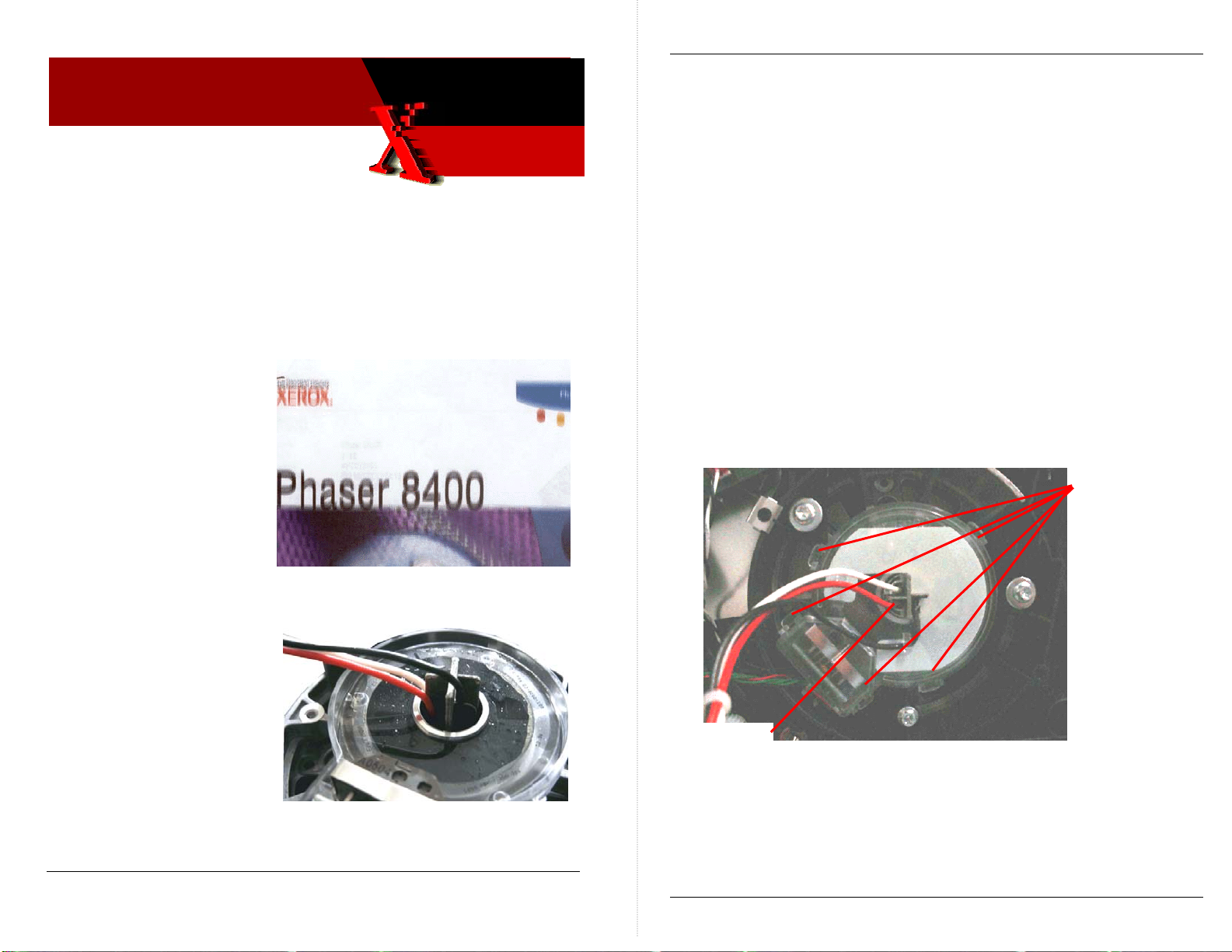
The problem is caused by oil
migrating from the drum
assembly’s bearing and
contaminating the encoder
disk as shown in Figure 2.
By design the encoder disk
is immune to some
contamination, but too much
contamination overwhelms
the system.
Figure 2
Phaser 8400 Xerox Office Group Service Bulletin SB 705
WHAT TO DO
Carefully disassemble the drum encoder’s cover to access the
encoder disk and then clean the disk.
1. Turn off the printer.
2. Remove the right side cover.
3. Remove the drum fan.
4. Disconnect the drum assembly’s encoder wiring harness from
the I/O board. Disconnect the drum heater wiring harness
from the drum relay board.
NOTE: Observe for reassembly how the AC wiring harness
routes thru the encoder disk cover and the heater
frame.
5. Free the encoder wiring from the encoder cover.
6. Carefully pry off the transparent encoder cover by releasing its
five snap-fit latches.
Snap-fit
latches
Note wire
routing
Figure 3
Hardware Issue Rev 0 Page 1 of 3
Copyright © 2003 Xerox Corporation. All rights reserved. XEROX®, the stylized X®, and Phaser®
trademarks of Xerox Corporation in the United States and/or other countries.
Page 2 of 3
Page 21

Phaser 8400 Xerox Office Group Service Bulletin SB 705
7. Gently feed the AC wiring thru the encoder cover to move the
cover out of the way.
8. With a cleaning swab, gently clean the oil off the encoder disk.
If available, use Xerox cleaning fluid (p.n. 008R90176) to “cut”
the oil.
9. Carefully reassembly the drum encoder. Be sure to correctly
route the drum heater AC wiring thru the encoder disk cover
and the heater frame.
10. Print some test prints.
PART INVENTORY STRATEGY
If cleaning repairs are not effective, replace the drum assembly,
p.n. 105-1150-08
TE
Page 3 of 3
Page 22
Xerox
Office
Group
Service Bulletin
01 Dec 2005
Phaser 8400/8500/8550
SB 709
Revised Service Manual Available
INFORMATION
An updated version of the Phaser 8400/8500/8550 Color Printer
Service Manual is available in PDF format. The files are available
on the in the Phaser 8400 and the Phaser 8500/8550 pages of the
Service Support website http://cpidserv.opbu.xerox.com/
same files are also accessible thru the Service Partner website
www.officeprinting.xerox.com/partners
The single-file version of the service manual is a change-bar
marked manual that indicates which topics are updated.
The individual chapter files do not contain the change bars.
The updated manual can be identified by the revision date
Oct 24, 2005 on the title page.
.
. The
WHAT TO DO
Download the manual files of your choice.
PART INVENTORY STRATEGY
Printed copies of the updated service manual will be available to
order in January 2006 using part number 721P58550.
TE
Service Manual Rev 0 Page 1 of 1
Copyright © 2003 Xerox Corporation. All rights reserved. XEROX®, the stylized X®, and Phaser®
trademarks of Xerox Corporation in the United States and/or other countries.
Page 23
p
Xerox
Office
Group
Service Bulletin
14 Dec 2005
Phaser 8500/8550
SB 711
Clarifications regarding using Jet Substitution and
the Light Stripes Test Page
INFORMATION
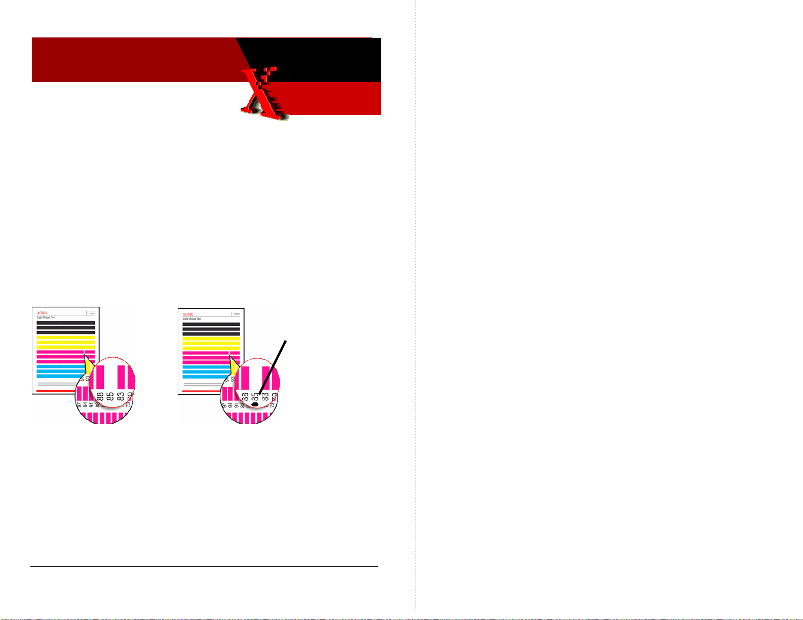
Use the Light Stripes Test Page to determine the jet number of an
unrecoverable weak or missing jet that you will want to fix using
jet substitution. A weak or missing jet will always appear weak or
missing on the Light Stripes Test print even when Jet Substitution
is being used. Once jet substation is activated, a small, black dot is
printed next to the jet number of a jet that will be substituted
during normal printing.
Jet Substitution
dot A sub’ed jet
will still show as
missing on Light
Stri
es print
Missing Jet Missing jet that will be substituted
during regular printing
WHAT TO DO
Note that Jet Substitution mode is enabled during normal printing
but is not used when printing the Light Stripes Test page.
PART INVENTORY STRATEGY
None TE
Repair Notes Rev 0 Page 1 of 1
Copyright © 2003 Xerox Corporation. All rights reserved. XEROX®, the stylized X®, and Phaser®
trademarks of Xerox Corporation in the United States and/or other countries.
Page 24
Xerox
Office
Group
Service Bulletin
14 Dec 2005
Phaser 8500/8550
SB 712
Only Newest Firmware-Version Electronics Module
(p.n. 137E14021) is Available; Uploading NarrowStyle Wiper Belt Snippet May Be Necessary
8,XXX.4X WIPER MOVEMENT ERROR CODES MAY OCCUR
IF PRINTER FIRMWARE AND WIPER DRIVE BELTS DO
NOT MATCH
Only replacement FRU electronic modules which contain the latest
version firmware are now orderable. These electronic modules
contain engine code version:
25.28.08.19.2005; PS: 4.8.0
. As detailed in Service Bulletin 701, this
firmware level implements metered printing capability as well as
support for wide-style wiper drive belts.
WHAT TO DO
When you install a replacement electronics module in a printer you
must verify what style of wiper drive belts are used in the printer.
vxWorks: 4.302; Engine: 18.P1.4.8.0; NW:
Phaser 8500/8550 Xerox Office Group Service Bulletin SB 712
If the printer uses narrow-style belt, you must upload the snippet
8500-8550useThinBelts.ps to set the firmware code to use narrow
wiper belts.
Snippets to set the electronics module’s firmware to work with
either narrow- or wide-style belts are available at:
Service Partners
http://www.office.xerox.com/partners/products/Phaser8500/Phaser8500Series.html
Internal Support
http://cpidserv.opbu.xerox.com/products/Phaser8500/Phaser8500Series.html
By default, the electronics module is set to work with wide-style
belts.
Be sure that the style of wiper drive belts matches the firmware
version of the electronics module.
Refer to Service Bulletin 701. Be sure that the firmware version of the
electronics module is correct for the style of wiper drive belts used.
FW Version 4.302 Default supp ort for wide wiper belts
Can be set to support narrow wiper belts
FW Version 4.278 Only support narrow wiper belts
Wiper movement error codes 08,xxx.4x may result if the firmware
does not match the wiper belts.
Narrow wiper drive belt Wide wiper drive belt
Repair Notes Rev 0 Page 1 of 2
Copyright © 2003 Xerox Corporation. All rights reserved. XEROX®, the stylized X®, and Phaser®
trademarks of Xerox Corporation in the United States and/or other countries.
PART INVENTORY STRATEGY
Order electronics modules only as needed.
Electronics Module 137E14021
Wiper Assembly – wide style 367053480
Wiper Drive Belts – wide style 214501280
8400/8500/8550
TE
Page 2 of 2
Page 25
e
Xerox
Office
Group
Service Bulletin
04 Jan 2006
Phaser 8400/8500/8550
SB 714
Jam Open Front Cover (C3T) after Replacing or
Reinstalling the Process Drive Assembly
PROCESS DRIVE ASSEMBLY ALIGNMENT PROBLEM
After replacing the process drive assembly, pivot plate or the drum
maintenance camshaft (or any other procedure requiring the removal
of the process drive assembly), the printer may experience jams from
Tray 2. The jam occurs with paper in the preheater and C3T jam errors
(strip flag timeout during transfix) recorded in the Jam History. In
many cases, Tray 1 (MPT) prints with no jams.
These symptoms indicate that the transfix load module is incorrectly
timed and is therefore not advancing the paper to the strip flag within
the correct timeframe. Therefore the printer reports a front cover jam
and records the C3T jam error.
WHAT TO DO
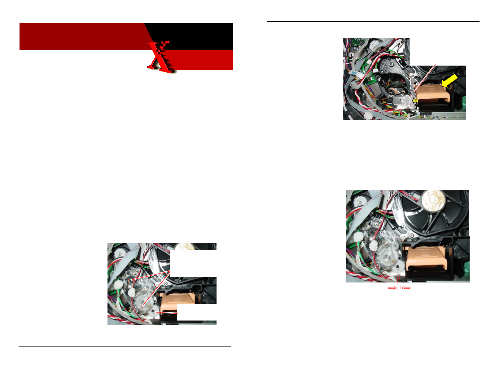
The majority of the time, the problem is that the drum maintenance
camshaft is out of position by one or two teeth. Correct by:
1. Rotate the drum
maintenance camshaft
clockwise to tilt the
printhead forward to its
home position. (This
disengages the
printhead and its tilt
gear from the camshaft.)
2. Pin the process drive
assembly to keep its two
missing tooth gears in their disengaged positions.
Repair Notes Rev 0 Page 1 of 2
Copyright © 2003 Xerox Corporation. All rights reserved. XEROX®, the stylized X®, and Phaser®
trademarks of Xerox Corporation in the United States and/or other countries.
Pin the process drive to
secure its missing tooth
gears
Drum maintenance
Phaser 8400/8500/8550 Xerox Office Group Service Bulletin SB 714
3. Remove the process drive assembly.
4. Press against the
drum maintenance
kit to force it (and
the pivot plate)
against the drum
maintenance cams.
This forces the
drum maintenance
shaft end gear to it
home position. The
camshaft’s homed
position is indicated by the hole in the drum maintenance
camshaft gear aligning with the embossed arrow on the metal
plate below the gear.
Note: When properly aligned, the hole in the camshaft gear points to the
6:00 or 5:30 position. If the hole does not point at the arrow, while the
DMU is being pressed against the cams, a cam may be broken on the
drum maintenance camshaft.
5. With the drum
maintenance
camshaft held in its
home position,
install the pinned
process drive.
6. Once the process
drive assembly is
secured in place,
remove the lock
pins.
Pivot Plat
Cams
Press and maintain
pressure against
DMU to force the DM
cams to their upright
home position
DMU horizontal
Camshaft gear
alignment hole should
be in this position
PART INVENTORY STRATEGY
None
TE
Page 2 of 2
Page 26
p
Xerox
Office
Group
Service Bulletin
20 Mar 2006
Phaser 8500/8550
SB 716 Rev 1
Installing Pick Clutch Ground Clip Prevents
19,005.4 Error Codes, Printer Hangs During
Printing, and some Jams Behind Front Cover
Phaser 8500/8550 Xerox Office Group Service Bulletin SB 716
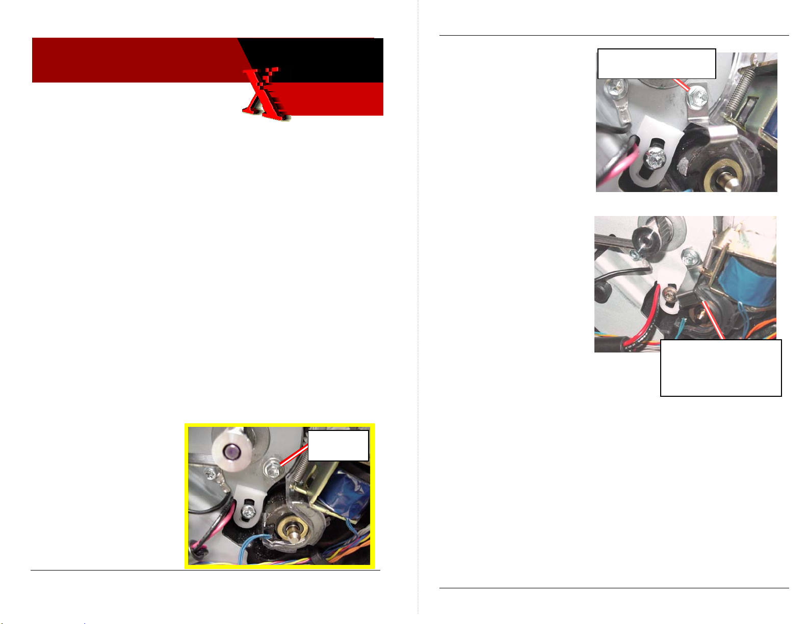
2. Loosely install the ground
clip and then the washer
with the screw you just
removed. The other end
of the ground clip should
contact the end of the
paper pick clutch.
Loosely install ground
cli
and washer
GROUND CLIP PREVENTS STATIC CHARGE BUILD-UP
Static build up at the pick roller during printing can lead to a static
discharge thru the pick roller clutch into the electronics module. This
results in either:
• A 19,005.41 error code displayed on the front panel.
• The printer hanging while printing with the electronics fan
on full.
• Occasional Jams Behind the Front Cover messages. This jam is
usually accompanied by error 19,005.41 in Fault History.
The static buildup occurs while printing in very low-humidity
environments.
WHAT TO DO
Install a ground clip from the Y-axis motor bracket to the pick clutch.
1. Remove the lower-right
Y-axis motor mounting
screw. It is the screw
closest to the paper pick
clutch.
Remove
screw
3. Position the ground clip
so its end rests against the
face of the pick clutch
body. The corner of the
ground clip end should
contact the plastic frame
of the media path drive
module.
4. Tighten the screw to
secure the ground clip in
position.
Position the clip so its
edge contacts the clutch
face and the plastic
housing
PART INVENTORY STRATEGY
Update any Phaser 8500 or 8550 you service with a static ground clip
as needed to solve 19,005.43 errors, some printer hangs during
printing, and random jamming behind the front cover.
Pick Clutch Ground Clip Kit - Part Number 650-4427-00
TE
Repair Notes Rev 0 Page 1 of 2
Copyright © 2003 Xerox Corporation. All rights reserved. XEROX®, the stylized X®, and Phaser®
trademarks of Xerox Corporation in the United States and/or other countries.
Page 2 of 2
Page 27
Xerox
Office
Group
Service Bulletin
Phaser 8500/8550
09-April-2006
SB 719
New Locking-Style ZIF Connector Being Used for
Printhead Flex Cable
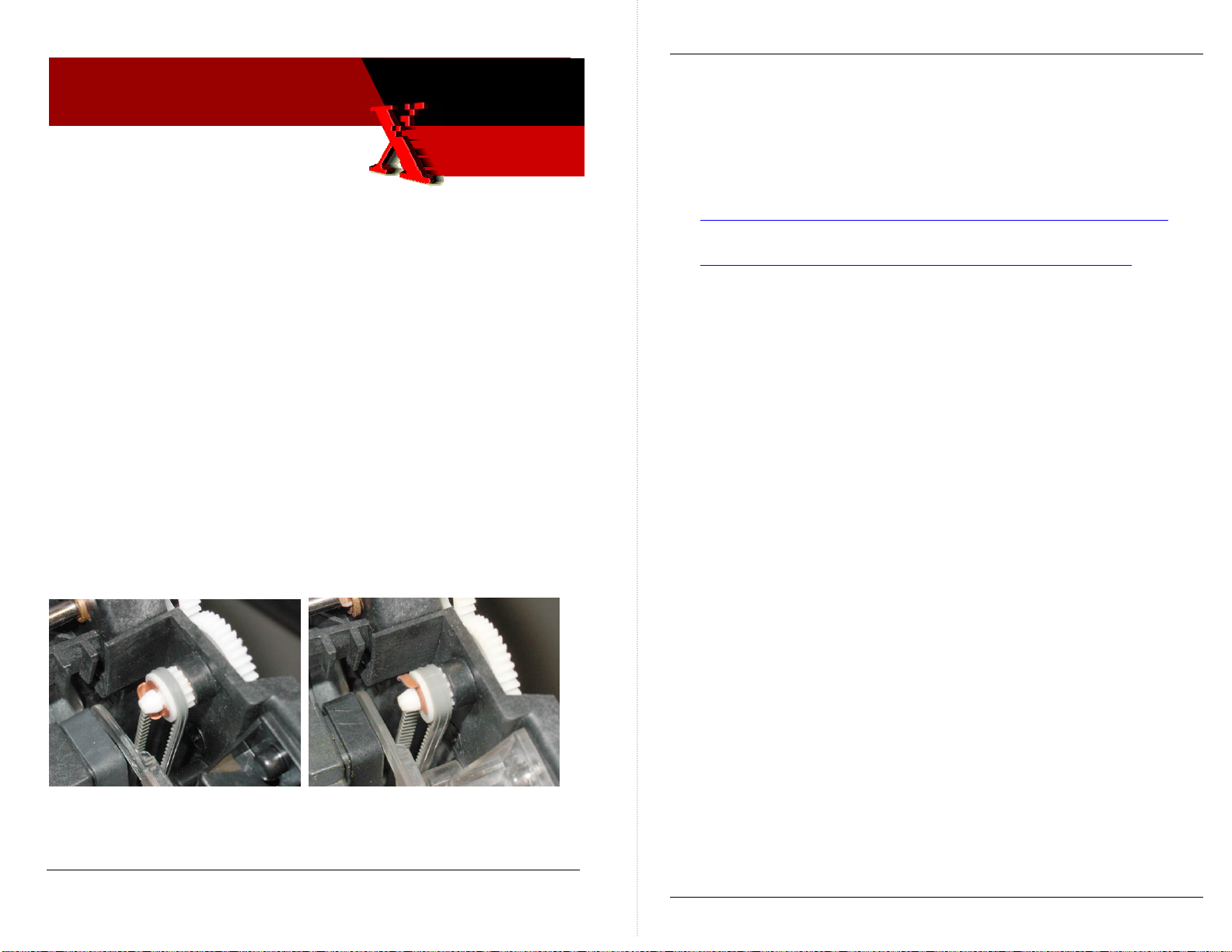
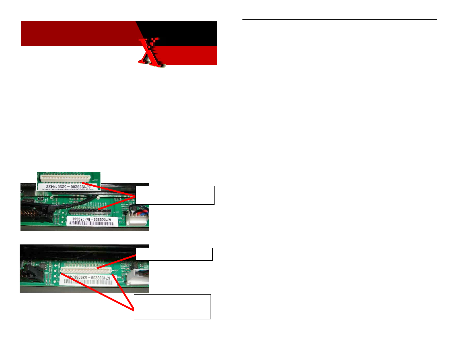
INFORMATION: THREE TYPES OF PRINTHEAD FLEX CABLE
CONNECTORS ARE USED; ONE OF THEM IS A LOCKING ZIF
CONNECTOR
Until recently, the Phaser 8500/8550 printers used two different non-locking
style flex cable connectors. In order to meet new Reduction of Hazardous
Substances (RoHS) standards, a third locking-style ZIF connector will be
used. It replaces the use of the previous two connectors. Only the new
locking-style ZIF connector meets electrical specifications and the RoHS
standards.
Non-locking style connectors
(white or black)
Locking style ZIF connector
Phaser Xerox Office Group Service Bulletin SB 719
WHAT TO DO
As you service a Phaser 8500 or 8550 printer, be aware that you may need to
unlock and lock the flex cable when disconnecting and reconnecting the
cable.
• Use care when locking and unlocking the connector.
• Failing to unlock a ZIF connector, before removing the cable, may
damage the connector.
• Ensure the cable is fully inserted into the connector before locking
the connector.
PART INVENTORY STRATEGY
None.
TME
Part Issue Error! Reference source not found. SB 719 Page 1 of 2
Copyright © 2006 Xerox Corporation. All rights reserved. XEROX®, the stylized X®, and Phaser®
trademarks of Xerox Corporation in the United States and/or other countries.
Lift up on small tabs on
each end of the connector
to release the lock
Page 2 of 2
Page 28

Xerox
Office
Group
Service Bulletin
11-April-2006
Phaser 8500/8550
SB 720
Printer Produces Gradually Lighter Prints
INFORMATION: PRINTERS BELOW SERIAL-NUMBER
WYP142312 AND WYN142344 BENEFIT FROM PRINTHEAD
FIRMWARE UPDATE
Printhead engineering has developed new drift compensation algorithms
that maintain the print quality/density of the Phaser 85xx printer’s printhead.
All printers serial-numbered below WYN142344 (Phaser 8550) and
WYP142312 (Phaser 8500) benefit from having their printhead’s firmware
constants updated via a downloadable snippet file. Printers above the serial
number break already have the new algorithm built in.
The snippet file and a readme file are contained in file 8500-8550_phfw-
update.zip. The file is available at:
http://www.office.xerox.com/perl-bin/product.pl?page=sprt&product=8500_8550
Follow the readme instructions to upload the snippet to a printer.
As the printhead ages over the years, the prints it produces will gradually
become lighter and lighter. There is no means to determine the printhead’s
firmware constants settings. Only downloading the snippet to the printer will
tell you if the printhead is up-to-date or not. Following the download, the
printer prints a download status print.
WHAT TO DO
As you service a Phaser 8500 or 8550 printer, check its serial number. If it
is below WYP142312 or WYN142344, download the printhead u pdate
snippet to the printer. For update tracking purposes, indicate in your call
closure details or notes that you have updated a printer with the printhead
snippet.
PART INVENTORY STRATEGY
None.
TME
Firmware Issue Error! Reference source not found. SB 720 Page 1 of 1
Copyright © 2006 Xerox Corporation. All rights reserved. XEROX®, the stylized X®, and Phaser®
trademarks of Xerox Corporation in the United States and/or other countries.
Page 29

Xerox
Office
Group
Phaser 850/860/8200/8400/8500/
8550/C2424
Service Bulletin
8 May 2006
SB 723
Back Channel Trace and Diagnostics using a
USB-to-Serial Adapter
USING A USB-TO-SERIAL PORT ADAPTER TO OBTAIN A
BACK CHANNEL TRACE OR TO RUN PHASER 850
DIAGNOSTICS
Many newer Laptops or PC’s do not have serial ports available. An
alternate method of communicating with the printers is available by
using a USB-to-Serial Port Adapter and its software to communicate
in a serial manner.
WHAT TO DO
Obtain a USB-to-Serial Port Adapter and software for your Laptop
or PC and Load the software as per the instructions provided.
An example of how to load and operate the Port Adapter is
provided below.
Obtaining a VX Works Trace using a USB Adapter – This method
was tested with a Phaser 850. You can also use the adaptor for
running external Diagnostics after modifying the Diags.INI file.
NOTE The instructions contained in this service bulletin were
developed using a Belkin USB/Serial Adapter, P/N F5U109
and the Windows XP O/S. Other USB-to-Serial adapters are
available; however software installation procedures may vary
by brand.
NOTE Xerox is not responsible for any changes made to your laptop
or PC setup to make the adapter software function properly.
Solid Ink Printers Xerox Office Group Service Bulletin SB 723
1. Load the software from the CD and reboot the PC. Follow
the instructions included with your adapter to install the
necessary software.
2. Connect the USB/Serial adapter to an available USB port on
your PC. Attach the port adapter to the 9 pin Serial cable
(012-1535-00) and the diagnostic pig tail (012-1543-00), and
plug it into the service port on the back of the printer
3. Configure the USB port for diagnostics. For Windows XP, go
to [My Computer] - [Control Panel] - [System], select the
[Hardware] tab, and then select [Device Manager]. Click on
the “+” next to [Ports (COM & LPT)], then right click on the
USB-to-Serial Port device and select [Properties]. Make a
note of the port number (usually COM3 or COM4)
NOTE Check the USB/Serial adapter instructions for
acceptable COM ports. Some adapters may require
that the adapter use COM3 or COM4.
4. Click on the [Port Settings] tab. Set “Bits per second” to 19200,
and set “Flow control” to Hardware, then click [OK].
5. Set up a Hyper Terminal port on the PC. Click [Start] -
[Programs] - [Accessories] - [Communications] - [Hyper
Terminal].
6. Name the new connection with the model number of the
printer. Configure the new connection using the COM port
configured in step 3, then click [OK]. Set “Bits per second” to
19200, and set “Flow control” to Hardware, then click [OK].
7. From the Hyper Terminal tool bar, click on [Transfer] and
select [Capture Text]. Click on [Browse], and in the browse
window, navigate to the desktop (or another file where you
wish to save your diagnostic results). Enter a file name for
your trace and click [Save].
8. For the Phaser 850, 860, and 8200 put rear panel DIP-switch 3
in the down position and turn on the printer. For the Phaser
8400/8500/8550 & C2424, no switch is needed. Follow the
Testing Issue Page 1 of 3
Copyright © 2004 Xerox Corporation. All rights reserved. XEROX®, the stylized X®, and Phaser®
trademarks of Xerox Corporation in the United States and/or other countries.
Page 2 of 3
Page 30

Solid Ink Printers Xerox Office Group Service Bulletin SB 723
instructions in the service manual for performing a
backchannel trace.
9. The backchannel trace should be displayed in the Hyper
Terminal window. When you have captured the necessary
trace data, click [Transfer] – [Capture Text] – [Stop] to end
data capture. This data will be saved as a text file to the
location specified in step #7, and may now be faxed or emailed to EHS for help with troubleshooting problems on
power up or other out of the ordinary problems where
normal diagnostics may not run.
PHASER 850 DIAGNOSTICS
To run diagnostics using a USB-to-serial adapter you must edit the
DIAGS.INI file to launch the correct baud rate and COM port. Edit
the file with a program such as WordPad. You will also need to
verify that your USB/Serial adapter software supports the COM
port you want to use. Some manufacturers may require that the
adapter is used on COM1 through COM4.
It is recommended that the NO-Floppy diagnostics from the
Partners Web site be used for easy diagnostic operation. Always
place switch 1 only in the down position on the Phaser 850 printer to
run diagnostics.
The following are the settings that need to be changed in the
DIAGS.INI file. Set the Port for the Com port you wish to use. The
baud rate is normally set at 19200. Save the file and launch
diagnostics.
PORT0 = COM1 baud: 0 = 9600
PORT1 = COM2 baud: 1 = 19200
PORT2 = COM3 baud: 2 = 38400
PORT3 = COM4
NOTE Beginning with the Phaser 860, all printers have
built-in diagnostics capabilities and do not require the
use of external diagnostics.
Page 3 of 3
Page 31

Date Issued: 16 Oct 2006
SB 733
Product: Phaser 8400, 8500, 8550, C2424
For the Phaser 8500/8550, obtain the file “setFreezeTemp92_85008550v2.ps” from:
http://download.support.xerox.com/pub/drivers/8500_8550/utils/wins2003/en/
setFreezeTemp92_8500‐8550v2.ps
For the Phaser 8400 and Workstation C2424:
Operational Groups: OPB, NADC
1. Print the Service Usage Profile (scroll to Troubleshooting: Service
PRINTER CONSUMES TOO MUCH INK DUE TO EXCESSIVE
AUTO-PURGES
When the printer transitions from its PowerSaver mode to its Ready
state, it unexpectantly performs an automatic cleaning cycle. This is
evidenced by a Cleaning Page (sometimes referred to as a mud page) in
the output bin.
Tools: Service Usage Profile).
2. Examine Token 281 Printhead Clean Count. Determine if the
item Manual shows a significant number of cleanings that do not
coincide with Token 287 PPC -- WP (warm purge). If instead,
Manual cleanings are being tallied under Token 287 PPC – CP
(cold purge), then abnormal auto-purges are taking place.
Additionally, the abnormal number of Manual cleanings (cold
purges) shown on Token 281 should correlate to the number of
CAUSE
auto-purges and mud pages experienced by the customer.
3. If the Manual clean count is high and cleanings are being tallied
Certain printhead conditions can cause the printer to incorrectly think
that the printhead is too cold while in the PowerSaver state. The printer
responds with a cleaning cycle when it reaches its Ready state. The
cleaning cycle is meant to purge any air bubbles that would have
formed in the ink when it was too cold.
as PPC CPs, then upload the appropriate “setFreezeTemp”
snippet file to the printer.
• For the Phaser 8400, obtain the file “8400-setFreezeTemp92.ps”
• For the Workstation C2424, obtain the file
“setFreezeTemp92_C2424.ps”
The snippets reprogram the printer’s printhead to make it more
SOLUTION
Determine if the printer has been performing too many auto-purges.
For the Phaser 8500/8550:
1. Print the Service Usage Profile (scroll to Troubleshooting: Service
Tools: Service Usage Profile).
2. Examine Token 281 to see if item CAP (Cold Abnormal Purge)
shows a more than 5 cleanings. The abnormal number of CAP
cleanings shown on Token 281 should correlate to the number of
auto-purges and mud pages experienced by the customer.
3. If the CAP count is high, then upload the “setFreezeTemp92_8500-
8550v2.ps” snippet file to the printer. The snippet reprograms
the printer’s printhead to make it more immune to the
conditions that cause the false printhead temperature reading.
Copyright © 2006 Xerox Corporation. All rights reserved. XEROX®, the stylized X®, and Phaser®
trademarks of Xerox Corporation in the United States and/or other countries.
immune to the conditions that cause the false printhead temperature
reading.
For the Phaser 8400, obtain the file “8400-setFreezeTemp92.ps” from:
http://download.support.xerox.com/pub/drivers/8400/utils/wins2003/en/8400‐
setFreezeTemp92.ps
For the Workstation C2424, obtain the file “setFreezeTemp92_C2424.ps”
from:
http://download.support.xerox.com/pub/drivers/C2424/utils/wins2003/en/setFreezeTem
p92_C2424.ps
Resolve a “too many auto-cleans” problem by uploading the
“setFreezeTemp” snippet to the printer. Only replace the printhead if
the snippet fails to correct the problem.
1 of 2
Page 32

PART INVENTORY STRATEGY
None
TME
Pub. No.:
Page 2 of 2
Page 33

Date Issued: 10 Oct 2006
SB 740
Product: Phaser 8500, 8550
Operational Groups: OPB, NADC
9,035.43 THRU 9,038.46 INK STICK COUNT FAULTS AND
FALSE INK OUT MESSAGES. SOME INK STICKS MAY NOT
RELIABLY ACTUATE INK OUT SENSORS
Features on the bottom of genuine Xerox Phaser 8500/8550 brand ink
sticks actuate the Ink Out Sensor located at the forward end of each ink
stick channel of the printer’s ink loader. The printer reads each sensor
to determine if an ink stick is present and also to count each stick as it
passes by the sensor.
Some ink sticks may not reliably depress an Ink Out Sensor’s flag. This
can lead to false Ink Out messages as well as Ink Stick Count faults.
Using Phaser 8400 ink sticks in a Phaser 8500 or 8550 will also cause
9,03x.4x ink stick count faults. The Phaser 8400 ink sticks do not have
the features required to actuate the ink out flags.
WHAT TO DO
When you service a Phaser 8500 or 8550 printer for:
• a persistent Ink Out message
• 9,035.43 Cyan Ink Stick Count Fault
• 9,036.44 Magenta Ink Stick Count Fault
• 9,037.45 Yellow Ink Stick Count Fault
• 9,038.46 Black Ink Stick Count Fault
Test the Ink Out Sensors for proper operation.
Inspect the Ink Sticks.
TESTING THE INK OUT SENSORS
Use this procedure to test if an Ink Out Sensor’s flag works correctly.
1. Remove ink sticks from the ink loader’s channels.
2. Place the printer in Diagnostics Mode by:
Service method
a. Turning on the printer and as
XEROX appears on the
screen, press and hold the
Back and Help button until
Beginning Service Mode
Initialization appears.
b. Scroll to and execute test
Monitor: Sensors
3. Insert the clean eraser end of a pencil thru the lowermost oval slot.
(The eraser end of a pencil closely simulates the bottom rail shape of
a Xerox ink stick.)
4. Slide the pencil down the white channel guide until the sensor is
tripped. A sensor change is displayed on the control panel. When
the flag is depressed, the front panel will read <color> Ink Present
H. When released, the reading will change to L. The test will only
display a reading when a sensor change occurs. If a flag is stuck, no
sensor reading will be displayed on the front panel.
Ink Out flag
Customer method
a. While error code displayed,
press UP arrow and OK key.
b. Scroll to Troubleshooting:
Service Tools: Enter
Diagnostic Mode. (Printer
restarts).
c. Select test 82: Monitor Sensors.
Press OK.
d. Scroll to 01: Exit Diagnostics and
press OK to return to customer
mode.
Depress Ink Out flag
with pencil eraser
Copyright © 2006 Xerox Corporation. All rights reserved. XEROX®, the stylized X®, and Phaser®
trademarks of Xerox Corporation in the United States and/or other countries.
1 of 2
Page 34

Y1,
5. If the sensors are not working properly, follow standard service
procedures and replace the ink loader assembly.
6. If the ink out sensors work correctly, identify the ink stick(s)
being used in the printer.
IDENTIFYING INK STICKS
If Genuine Xerox Phaser 8500/8550 Ink Sticks are being used, check
for defects in the ink sticks and replace. If no defects are found,
replace the ink loader assembly.
• If Phaser 8400 Ink Sticks are being used, they will not properly
actuate the ink loader sensors. Do not use Phaser 8400 ink sticks
in a Phaser 8500 or 8550 printer.
Xerox Phaser 8500/8550 Ink
•Symbolic shapes
•Interlocking ends
•Smooth “ski-jump” bottom
•Single notch on guide rail (not found on
Phaser 8400 ink sticks)
•Slot number molded in bottom: 1, 2, 3, 4
Media Science Ink (non Xerox Ink)
•“Squarish” shapes
•Flat ends
•Flat bottom
• If non-Xerox ink is being used, the shapes of these sticks are
different than genuine Xerox Phaser 8500/8550 ink and may not
properly actuate the ink loader sensor(s). Remove all non-Xerox
ink and re-load with genuine Xerox Phaser 8500/8550 ink and
check sensor operation. If proper function returns to the printer,
the false error message was caused by the use of non-Xerox ink.
If the false error message continues, replace the ink loader
assembly.
Note: Xerox is not financially responsible for the incorrect
operation of its products caused by the use of nonXerox ink.
•Two symmetrical, flat-bottom rails with notch
•Slot number molded in bottom: 1, 2, 3, 4
Inknara Ink (non Xerox Ink)
•Symbolic shapes that duplicate Xerox shapes
•Ends do not interlock
•“Layered” bottom with cylindrical guide rail
•Notch on both ends of guide rail
•Color and Slot numbers molded in bottom:
C2, M3, K4
Xerox Phaser 8400 Ink
•Symbolic shapes
•Interlocking ends (different from 8500/8500)
•Smooth “ski-jump bottom
•No notch on end of guide rail
•Color number molded in bottom: 1, 2, 3, 4
PART INVENTORY STRATEGY
None
TME
Pub. No.:
Page 2 of 2
Page 35

Date Issued: 08 Jan 2007
SB 741
Product: Phaser 8500/8550
Operational Groups: All
PROBLEM:
Phaser 8500/8550 control panel assemblies previously included the grey
control panel ribbon cable. The control panel cable (connects the control
panel to the I/O board) is no longer included with the control panel
assembly.
CAUSE:
In many cases, control panels are now being shipped directly to
customers for replacement of failed displays. The control panel cable is
not customer-replaceable and is no longer included with the control
panel assembly.
PART INVENTORY STRATEGY
Only order this part as needed.
Complete the part’s green card and include it with each part returned.
North America: Return replaced parts to the logistics center named on the
shipping box’s pre-printed return shipping label.
Outside North America: Return parts as per your normal channels.
JK
SOLUTION:
The control panel cable is now spared under its own service part
number (117E35230).
Add the control panel cable (117E35230) as item 19 of PL 5.0 in your
8500/8550 service manual.
Failures of the control panel cable should be very rare. If the symptom
indicates a problem with the control panel, it is most likely the control
panel itself at fault.
Copyright © 2004 Xerox Corporation. All rights reserved. XEROX®, the stylized X®, and Phaser®
trademarks of Xerox Corporation in the United States and/or other countries.
1 of 1
Page 36

SERVICE BULLETIN
Date Issued: 09 April 2007
SB 745
PRODUCT: Phaser 8400, 8500, 8550,8560, 8560MFP,
WorkCentre C2424
SUBJECT: Criteria to Determine if Printhead Failure
Caused by the Printer Being Tipped While Hot
OPERATIONAL GROUPS: ALL
PROBLEM
Several problems can be associated with a Printhead that tipped
while hot including Massive Jet Loss, Ink Reservoir Overflow, and
Ink in the Air Purge Hose.
CAUSE
Tipping the printer while the Printhead is still hot. The printer
should be powered off and allowed to cool for 30 minutes before
moving.
SOLUTION
Overview
The solid-ink printer, while in its powered-on state, contains
liquefied ink. Only when the printer has been turned off and
allowed to cool for 20-to-30 minute does this ink solidify. Once the
ink has solidified can the printer be safely moved or shipped.
While its ink is in a liquid state, tipping or tilting the printer allows
ink to infiltrate upper portions of the printhead. This ink infiltration
causes serious, multiple jet loss and well as ink overflows. The ink
blocks the flow of pressurized air thru the purge hose into the
printhead during a cleaning cycle; purges become ineffective.
Similarly, air in the reservoirs is block by the ink so it cannot vent
out as ink is melted into the reservoir. Since the ink cannot
displace the trapped air, it backs up the ink reservoir funnel and
overflows.
Tipping the printer allows ink in the reservoir chambers ...
to flow thru the hole surounding the ink level sense probe ...
into the upper air chamber ...
where it can block the ink hose port.
Check valve
Air Hose port
Funnel
Figure 1. Cutaway view of printhead revealing interior
features. The dotted line indicates the air spaces above the
ink reservoirs.
Bulletin Contact: Terry Ennis E-Mail: terry.ennis@xerox.com
USSG SLDS Codes: B26, B34, B71 April 09, 2007 Page
1 of 1
Page 37

SERVICE BULLETIN
Air chamber
Ink level
sense probe
Hole connecting
air chamber
to ink reservoir
Ink flows in funnel
thru the filter and
then thru one-way
check valve into
Ink reservoir
Figure 2. View of printhead with plastic insulation panels
removed
ink reservoir
Figure 3.
Ink Reservoir Overflow
Following an ink melt cycle, look for:
• An abnormally raised level of ink in a reservoir (shown in
the Magenta reservoir). Ordinarily the ink level is
maintained even with the filters in the reservoir (as shown
in the Black reservoir). Ink should not rise above the
filters.
• If the ink level rises high enough it overflows and leaks
between the metal reservoir funnel and the plastic
insulating panels. (See Figure 4).
Ink in Air Purge Hose
Look for:
Ink in the purge hose where it connects to the printhead. This is a
sure sign the printer was tipped while hot. Ordinarily the hose
appearance is uniformly translucent. See Figure 3.
Bulletin Contact: Terry Ennis E-Mail: terry.ennis@xerox.com
USSG SLDS Codes: B26, B34, B71 April 09, 2007 Page
2 of 1
Page 38

Look for:
• Ink accumulations under the printhead or on the
printhead’s circuit board. Successive ink melt cycles and
overflows cause ink to accumulate under the printhead.
SERVICE BULLETIN
Massive jet loss
Look for:
• Many missing jets in the same color. May be in multiple
colors. See Figure 6.
• If there are ink accumulations under the printhead (Ink
Reservoir Overflow), then the printer was probably tipped
while it was in a typical user setting.
• Ink accumulations often lead to printhead movement faults
such as 7,010.43. (See Figure 5)
Figure 5.
The ink melted to fill the reservoir cannot immediately displace the
air trapped in the reservoir. Instead the ink backs up in the ink
reservoir funnel and overflows. Since the ink overflows between
the metal reservoir and the printhead’s plastic panels it is not
immediately apparent that the overflows are taking place. Only
after numerous ink melt cycles, which may be hours or days later
after the printer was tipped, does the problem reveal itself.
Multiple missing jets may occur during high-coverage printing due
to ink starvation. Since the ink is not refilling the reservoir, the
printer prints to the point that there is not enough ink to supply the
jets and they run dry. This failure will look similar to the illustration
in the next topic, Massive Jet Loss.
• If the lost jets occur when the printer is powered up, but
there are no indications of Ink Reservoir Overflow as
described earlier, then the printer was probably tilted (while
still hot) after it was shut down.
Air bubbles form in the ink when the ink cools and solidifies
following the shutdown. A power-up cleaning cycle flushes the airbubble laden ink out of the printhead. If the purge hose is block by
ink and cannot properly pressurize the printhead, then the purge
cannot flush out the air bubbles that formed in the ink when the ink
solidified. The jet loss is due to air bubbles in the printhead due to
an ineffective purge cycle.
Bulletin Contact: Terry Ennis E-Mail: terry.ennis@xerox.com
USSG SLDS Codes: B26, B34, B71 April 09, 2007 Page
3 of 1
Page 39

Date Issued: 17 April 2007
SB 746
Product: Phaser 8560
Operational Groups: DMO
PART NUMBERS FOR DEVELOPING MARKETS
ORGANIZATION’S PHASER 8560W PRINTER
A version of the Phaser 8560 with a different set of ink shapes is being
introduced in the DMO. It is labeled Phaser 8560W. The table below
lists the parts relevant to servicing this printer.
Name Part Number
Printhead 046K00530
Ink Loader Assy and Door 103K01600
8560W Genuine Solid Ink Cyan 3 Sticks 108R00764
8560W Genuine Solid Ink Magenta 3 Sticks 108R00765
8560W Genuine Solid Ink Yellow 3 Sticks 108R00766
8560W Genuine Solid Ink Black 3 Sticks 108R00767
8560W Genuine Solid Ink Black 6 Sticks 108R00768
8560W Genuine Solid Ink Rainbow Pack 108R00769
The yield on these ink shapes is approximately 1300 pages per stick.
Record these part numbers in your service manual. These updates will
be reflected in the next electronic update to the service manual.
TME
Copyright © 2004 Xerox Corporation. All rights reserved. XEROX®, the stylized X®, and Phaser®
trademarks of Xerox Corporation in the United States and/or other countries.
1 of 1
Page 40

Date Issued: 05 Oct 2007
SB 755
Product: Phaser 8560/8560MFP
Operational Groups: All
PROBLEM: EXCESSIVE INK USAGE/PURGING
Customers observe excessive ink consumption due to printhead
cleaning cycles.
CAUSE:
This behavior is most likely caused by Energy Star mode being enabled
and active. Energy Star mode forces machines to lower their printhead
temperatures below the freeze-off temperature level. Upon wake-up, the
machine will consume significant amount of ink while performing a
purge cycle.
Note:
Energy Star mode is only activated at the factory when the specific
model is ordered.
SOLUTION:
When troubleshooting a machine exhibiting the above behavior; use the
following steps:
1. Validate that the machine is an Energy Star model by the following
methods:
8560
During power-on the machine will display the Energy Star logo on
the control panel. It follows the XEROX splash screen.
8560MFP
Note the Energy Star label applied to the front of the machine.
2. Print a Service Usage Profile and inspect the Print Head Clean
Source (Token 282). Evaluate the CAP category, as it will be
incremented every time the machine initiates an EnergyStar purge.
3. After validating the issue is related to the Energy Star behavior;
follow these steps:
a. Explain to the customer that ink is being consumed because
their machine is cleaning the printhead before printing. Autopurging only occurs if the machine is turned off and on, or has
remained idle long enough to go into Energy Star mode.
b. Explain to the customer that we can fix the problem by disabling
Energy Star, but their machine will no longer comply with the
newest EnergyStar standard (TEC). The machine will still meet
the previous EnergyStar standard.
c. Disable Energy Star; ONLY
at the customer’s request.
Disabling EnergyStar mode
8560:
a. Select the Printer Setup menu via the control panel
b. Select the Printer Controls menu
c. Select Power Saver: On
d. Change Power Saver to OFF
Note:
The Power Saver menu item is only available on printers that
have had Energy Star mode activated by the factory.
8560MFP:
a. Locate the “8560MFP_ESTAR_OFF.ps” file on the Xerox
Driver/Utilities website and download to a local computer.
Copyright © 2004 Xerox Corporation. All rights reserved. XEROX®, the stylized X®, and Phaser®
trademarks of Xerox Corporation in the United States and/or other countries.
1 of 2
Page 41

http://download.support.xerox.com/pub/drivers/8560MFP/utils/winvistax64/e
n/8560MFP_ESTAR_OFF.zip
b. Open the “Readme.txt” file for download instructions.
c. Download the “8560MFP_ESTAR_OFF.ps” file.
d.
e. To verify that Energy Star has been disabled; monitor the
machine for 5 minutes. The machine should stay in READY
mode during this timeframe. If the machine enters STANDBY
mode, this means that EnergyStar is still active. The previous
step must be repeated until EnergyStar is disabled.
PART INVENTORY STRATEGY
N/A
TME/CRA
Pub. No.:
Page 2 of 2
Page 42

Date Issued: 12 Dec 2007
SB 759
Product: Phaser 8500 8550 8560 8560MFP 8860 8860MFP
Operational Groups: OPB, NADC, DMO
SERVICE BULLETIN
ERRATIC BEHAVIOR IN PRINTERS AND MFPS CONFIGURED
WITH 768 MBYTES OF RAM
Printers configured with 768 Mbytes of RAM (one 512 MB and one 256
MB RAM DIMM) may experience erratic behavior such as hanging on
power up, hanging or restarting during printing, or restarting when
coming out of Power Saver mode.
CAUSE
The presence of a 512 MB DIMM in Slot 1 (top slot) together with a 256
MB DIMM in Slot 2 (bottom slot) triggers the erratic behavior.
Dual-rank 512 RAM DIMMs (noted by the code HDY in the part
number printed on the DIMM) in the top slot exhibit the most erratic
behavior. Single-rank 512 RAM DIMMs (noted by the code HY in the
part number printed on the DIMM) in the top slot perform better but
are still prone to hangs and restarts.
RAM HANDLING TIPS
• Use static electricity safeguards when handling RAM. Ground
yourself to the printer frame before touching RAM DIMMs.
• Use proper techniques to remove RAM DIMMs from their
connector.
• Use a single fingertip to release the plastic connector latch at
each end of the RAM DIMM.
• Gently press slightly outward on the latch to release it.
• Release the latches one end at a time. The RAM DIMM will
pop forward when released.
SOLUTION
Ensure that the 512 MB RAM DIMM is installed in Slot 2 (bottom slot).
In testing no erratic behavior has been noted when the 512 MB RAM
DIMM is installed in Slot 2.
The erratic behavior has only been noted in printers with a 512 and a
256 RAM DIMM installed. Other DIMM combinations such as 512
alone, 512/512, 256 alone, and 256/256 performed as expected.
Copyright © 2007 Xerox Corporation. All rights reserved. XEROX®, the stylized X®, and Phaser®
trademarks of Xerox Corporation in the United States and/or ot her countries.
• When installing a RAM DIMM, ensure the RAM DIMM is fully
seated in the connector before tilting the DIMM back to lock it in
the connector.
PART INVENTORY STRATEGY
None.
TME Pub. No.: 759
1 of 1
Page 43

Date Issued: 13 February 2008
SB 762
SOLUTION
Product: Phaser 8560, 8560MFP
Operational Groups: OPB, NADC, DMO
When you encounter a squeaking bushing, replace both bushings.
The replacement bushings must securely engage the ground plane to
avoid static build-up.
PROBLEM: SQUEAKING DURING PRINTING DUE TO DRY
BUSHINGS
A small number of printers may start to produce a squeaking noise
during printing due to defective bushings installed in the printer's rightside frame. The bushings will likely fail (squeak) early in the printer's
life. Most likely within less than 1,000 prints. The problematic bushings
are only installed in the right-side frame and support the take-away
roller shaft and the duplex-roller shaft.
Take away
CAUSE
roller bushing
If the noise persists after replacement, the shaft may need to be replaced
The bushings in question were not impregnated with oil by the bushing
vendor.
(due to the printer being used for a long time with the defective
bushing).
NOTE
: A special process is used to impregnate bushings
with oil. Simply applying oil to dry bushings will not
adequately lubricate them.
PARTS INVENTORY STATEGY
Two 6mm, oil-impregnated brass bushings are available in a new
bushing kit. Part number: 604K55030 Bushing FRU Kit
TME
Pub. No.:
Copyright © 2004 Xerox Corporation. All rights reserved. XEROX®, the stylized X®, and Phaser®
trademarks of Xerox Corporation in the United States and/or ot her countries.
Duplex roller
bushing
1 of 1
Page 44

Date Issued: 5 March 2008
SB 763
Product: Phaser 8400, 8500, 8550 8560, C2424, 8560MFP
Identifying Xerox Phaser 8400/C2424 Ink Sticks
Phaser 8400
Operational Groups: OPB, NADC, DMO
Symbolic shapes
Interlocking ends
IDENTIFYING XEROX INK
This bulletin provides information to help you distinguish Xerox ink
from non-Xerox-ink. Xerox ink sticks feature several distinct, patented
features that make them easy to identify as well as improve feed
reliability in the printer.
Smooth “ski-jump" bottom
No notch on end of guide rail
Slot number molded in
bottom: 1, 2, 3, 4
Identifying Xerox Phaser 8500/8550 and 8560/8560MFP Ink
Sticks
Phaser 8500/8550
Interlocking ends
Symbolic shapes
WorkCentre C2424
same features as Phaser 8400
except key interlock is different
Smooth, “ski-jump” bottom
Single notch on guide rail
Typical Xerox packaging
Phaser 8560/8560MFP
same features as Phaser 8500/8550
except key interlock is different
Slot number molded in
bottom: 1, 2, 3, 4
Copyright © 2008 Xerox Corporation. All rights reserved. XEROX®, the stylized X®, and Phaser®
trademarks of Xerox Corporation in the United States and/or ot her countries.
1 of 2
Page 45

Identifying typical Non-Xerox Ink Sticks
Media Science Ink
•“Squarish” shapes
•Flat ends
•Flat bottom
•Slot number molded in bottom: 1, 2, 3, 4
•Two symmetrical, flat-bottom rails with notch
Typical Media Science packaging
WHAT TO DO
When you determine non-Xerox Ink is being used in a printer, report
it in the job notes. Proceed with the service visit as per standard
procedures.
Note Customers are free to use any brand of compatible ink or
TME
Pub. No.:
supplies they wish in their printer. However Xerox is not
responsible for damage or printer malfunction caused by the
used of non-Xerox supplies. Such damage is not covered by
the printer warranty.
Hana Ink
•Symbolic shapes that duplicate Xerox shapes
•Ends do not interlock
•“Layered” bottom with cylindrical guide rail
•Color and slot numbers molded in bottom:
Y1, C2, M3, K4
•Notch on both ends of guide rail
Typical Hana packaging
Page 2 of 2
Page 46
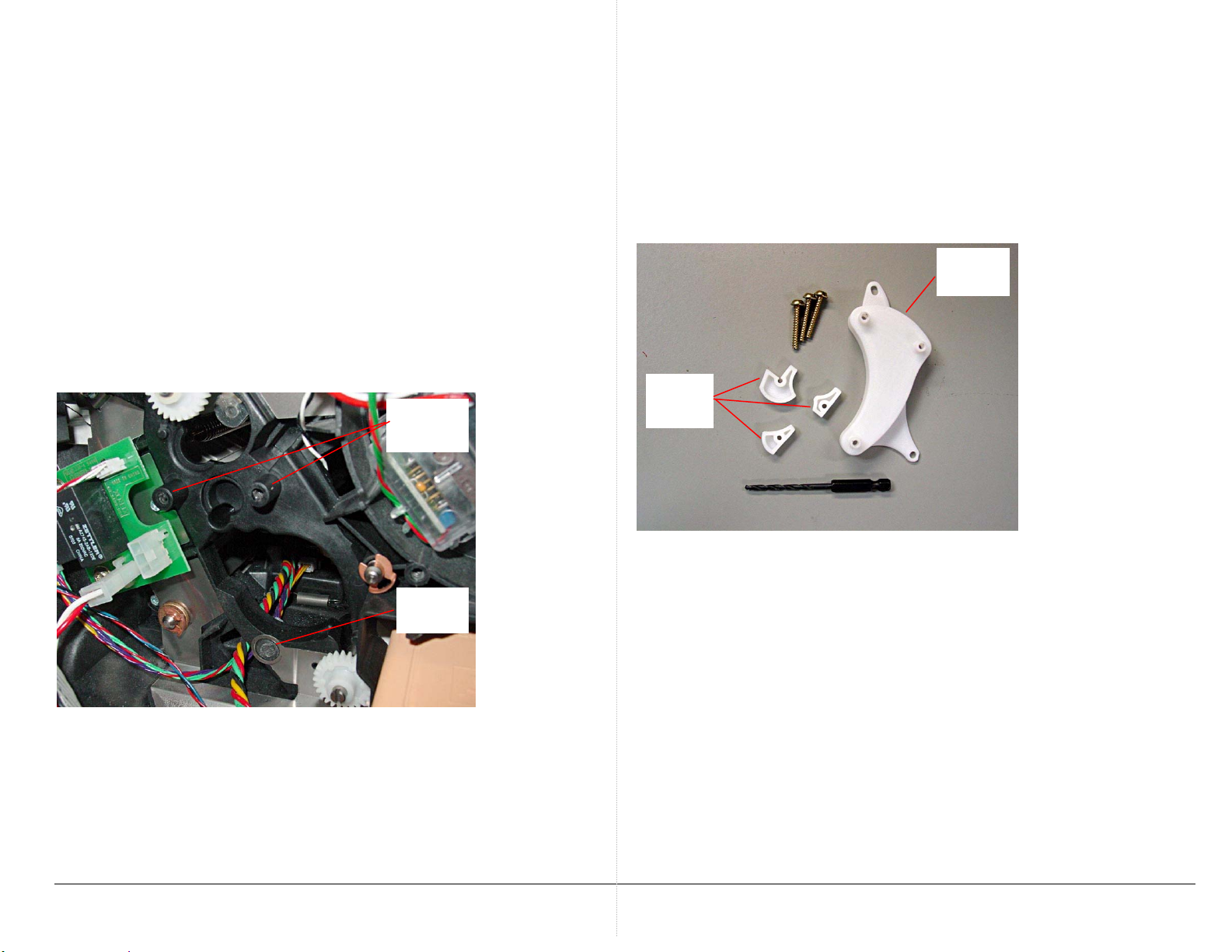
p
Date Issued: 21 Apr 2008
SB 766
Product: Phaser 8400, 8500, 8550, 8560, 8860, C2424,
8560MFP, 8860MFP
Operational Groups: OPB, NADC
The components of the kit are illustrated below. The kit contains a drill
fixture, a drill bit, the long screws, and three specially-shaped nut plates.
The kit also includes instructions for installing the repair parts.
The repair consist of removing the short process drive mounting screws,
drilling out the posts thru the printer frame, and installing long screws
with backer nut plates.
PROCESS DRIVE MOUNTING POST REPAIR KIT NOW
AVAILABLE
Drill
fixture
A repair kit is now available to repair printers that experience broken
process drive mounting posts.
Unbroken
posts
Nut
plates
When you repair a broken post, you should install all three post repair
parts to strengthen each of the three mounting posts, even if the others
Broken
ost
posts are not broke.
PART INVENTORY STRATEGY
Order the repair kit when necessary; part number 604K55230.
For Europe and DMO-East an alternate kit is optionally available. It
utilizes metal plates and studs to secure the process drive gearbox.
Instructions are included. The part number for the European kit is
604K54910
TME
Pub. No.:
Copyright © 2008 Xerox Corporation. All rights reserved. XEROX®, the stylized X®, and Phaser®
trademarks of Xerox Corporation in the United States and/or ot her countries.
1 of 1
Page 47

Date Issued: 12 May 2008
SB 768
Product: Phaser 8400, 8500, 8550, 8560, 8860, C2424,
8560MFP, 8860MFP
Operational Groups: OPB, NADC
Troubleshooting the 7,010.43 error code
The 7,010.43 error code indicates the printer is having difficulty tilting
the printhead forward from the parked position to the print position.
There are several printer systems involved in tilting the printhead so
troubleshooting the error can be challenging. The printer does not
directly sense the printhead's tilting position. Instead it applies drive
current to the process drive motor, and monitors the motion of the
motor's rotation encoder for "following error". For a particular drive
voltage the encoder should rotate at a particular rate as the printhead
(driven thru the process drive, the DM camshaft, and the head tilt gear
train) tilts forward. If the printer does not see the expected encoder
readings it assumes a tilt failure.
These instructions are also useful for troubleshooting the less common
7,007.49, 7,008,41, and 7,009.42 error codes.
• When you encounter a 7,010.43 error, determine when the
7,010.43 fault occurs.
• Does it occur during boot-up the first time the printer
attempts to tilt the printhead forward? If so, go to topic
"Fails on First Tilt".
• Does it occur later in the boot process after successfully
tilting a few times but failing when it begins to start a
cleaning cycle? If so go to "Fails on Subsequent Tilt".
FAILS ON FIRST TILT
When the printhead fails to tilt forward on the first tilt, it is often due to
something physically interfering with the printhead movement:
1. On rare occasions, you may find the printhead appears to be
stuck to the wiper blade. This can occur if the printer was
improperly shut down while performing a printhead cleaning
cycle.
2. In this case:
a. Allow the printhead to heat up to soften the ink.
b. Gently separate the printhead from the wiper.
c. Manually lower the wiper (by rotating the wiper drive
gear) and set the printhead into the print position next
to the drum.
d. Restart the printer.
Copyright © 2008 Xerox Corporation. All rights reserved. XEROX®, the stylized X®, and Phaser®
trademarks of Xerox Corporation in the United States and/or ot her countries.
1 of 7
Page 48

3. Is the printhead being centered by the X-axis motor? Does it
stay centered? Watch the left-right motion of the printhead.
Also watch for smooth left-right movement; if the nose-cone
threads are stripped, the printhead movement may be jerky
and irregular. When the printhead is tilted forward in the print
position, the X-axis nosecone is always in contact with the
printhead's stub shaft. When the printhead is tilted backwards
into its parked position, the X-axis nose cone is retracted away
from the printhead (no contact).
The printhead should travel all the way to the left (home) and
then halfway back to be centered to the drum. Once centered,
the printhead can then tilt forward. If the printhead does not
move left-right:
a. Check for ink in the roll block (from an ink overflow).
If you find ink in the roll block, power the printer up in
Service Diagnostics and run the Exercise Heaters: All
Heaters On test. This will soften the ink and allow you
to remove the ink block (it will be hot!) to clean it.
c. Does the motor rotate? If not either the motor is bad
and must be replaced or the motor drivers in the
electronics module are bad and the electronics module
must be replaced.
d. Does the X-axis motor hold the printhead in the
centered positioned? If it does not, either the motor is
failing or the motor drivers (in the electronics module)
are bad.
4. At the left side of the printer verify that the printhead X-axis
return spring hook is correctly located in the printhead's leftend stub shaft at the center of the roll block (shown in the
photo above). Ensure the spring and spring hook are not
obstructed or interfering with the printer frame.
5. Verify that the process drive assembly is correctly timed as
described in the topic "Homing the Process Drive Train" in the
service manual and Service Bulletin 714.
Check for ink in
the roll block
b. Does the X-axis motor rotate? If the printhead is not
pushed right-left, remove the x-axis motor and restart
the printer.
Page 2 of 7
Roll block and bias spring
X-axis return spring hook
Broken process drive
mounting post
Ensure none of the process drive mounting posts are broken. If
you encounter a broken post, repair it using the 604K55230
Broken Post Repair Kit. Refer to Service Bulletin 766. In
Europe you can optionally use repair kit 604K54910.
Page 49

6. Is one of the printhead restraints cracked? It may be necessary
to remove the restraints to verify whether cracks are present.
Check the printhead
restraints for cracks
7. Inspect the gray printhead data cable. Has the data cable choke
coil fallen behind the printhead? The choke coil should be
attached by Velcro. Also verify that the printhead heater
wiring harness, next to the gray ribbon cable, is also properly
dressed and restrained.
8. Is each printhead restraint lock arm lowering when the wiper
assembly is lowered? Verify that the printhead is centered and
not in contact with the lock arms. If the spring-loaded lock
arms do not freely move, replace the printhead restraint.
Lock arm properly
lowered
Printhead data cable choke
coil in correct location
Printhead heater wiring
harness in restraint
Page 3 of 7
Lock arm stuck in
raised positioned
Page 50

9. Check for ink spills or shards in the roll block and under the
printhead. At the left side of the printer examine the roll block
and printhead stub shaft for evidence of ink. Remove the
waste tray and examine the area under the printhead for ink
accumulations. Also look for ink shards under the DMU.
Look for shards of
ink in the waste tray
cavity
10. If there is evidence of ink under the printhead, there could be
ink in the printhead tilt gear train. Remove the printhead and
inspect the tilt gear train for shards of ink.
Tilt gears
(printhead
removed)
Page 4 of 7
Page 51

11. Inspect the drum maintenance (DM) cams for cracks. Most
often it is the right cam that cracks. Remove the DMU and lift
the pivot plate out of the way to inspect the right cam. Note: It
is possible to have a cracked cam that still functions normally.
Even so, replace a cracked DM camshaft when you find one.
Check for cracked DM
cams
12. If the DM camshaft was previously removed it is possible that
the left-end bushing fell out of place from the inside of the leftside frame. Verify the bushing is in place. If the bushing falls
out of place, it usually ends up under the Y-axis motor body.
Break in the new roller by doing the following:
a. Turn off the printer
b. Remove the left and right covers.
c. Manually raise the DMU into contact with the drum by
lifting it by its handle. Hold it against the drum.
d. Rotate the drum for about 50 revolutions by turning the
drum pulley on the left end of the drum.
e. Reassemble the printer and test.
2. Inspect the DM cams for cracks. (Illustrated in Step 11 of
previous topic.) Most often it is the right end cam that cracks.
Remove the DMU and lift the pivot plate out of the way to
inspect the cam. Note: It is possible to have a cracked cam that
still functions normally if the cam has not spun out of position
on the shaft. If a cam is cracked, replace the camshaft
assembly.
3. If the drum maintenance camshaft was replaced, it is possible
the right side ground plane was bent or bulged-out. This
ground plane bulge can force the right end bushing and DM
gear against the process drive gear train adding friction load
into the system.
FAILS ON SUBSEQUENT TILT
When the printhead fails on a subsequent tilt, it is usually caused by
something adding more drag or friction into the tilt drive system. The
printhead tilts forward at certain times during power–up but faults while
making the precise positioning needed for a printhead clean cycle.
Was a new Drum Maintenance Unit recently installed? The oil roller of
new DMU may be stiff, especially if cold. During the printhead tilt cycle
the DMU is lifted against the drum. If it is too stiff it may exert extra
drag into the system.
Page 5 of 7
The ground plane should
be flush against the
black side frame
Note for removing a bushing from a ground plane: Use a
rotating, twisting motion on the bushing instead of pulling it.
Page 52

4. Check the action of the printhead overload spring. When the
p
g
printhead is tilted back it presses down against the overload
spring. As the printhead tilts forward the spring pushes up
against the printhead. If the spring is dragging against another
object such as the X-axis return spring or the printer frame that
can change the load on the tilt system and the printer may
declare a fault. Inspect the overload spring for interference and
a smooth lift action.
Printhead X-axis return
rin
s
Ensure the printhead
overload spring moves
freely and does not
interfere with the X-axis
return spring
5. A lack of grease on drum maintenance cams-to-pivot plate
contacts points could induce more drag into the system.
Remove the paper preheater to inspect the contact points.
Grease if necessary (use Nye Rheolube 368, part number
070E00890). You will need to remove the Y-axis motor to
access the left end of the pivot plate if greasing the contact
points is needed.
Ensure the points where
the drum maintenance
cams contact the pivot
plate are lubricated
Page 6 of 7
Page 53

CHECK THE HEAD TILT ENGAGE MECHANISM
1. Verify the head tilt engage mechanism engages and
disengages. When the head tilt has been reset (by manually
rotating the drum maintenance camshaft one revolution) the
two arrows on the left side of the printer frame point at each
other indicating head tilt is disengaged. (This is described in
the Adjustments and Calibrations chapter of the service manual.)
The arrows point to each
other when the tilt
mechanism is disengaged.
Remember: the printhead must be centered to the drum prior to
rotating the drum maintenance cam to reset printhead tilt
engagement. If the printhead is not centered use a small flatblade screwdriver to turn the X-axis motor shaft to center the
printhead.
Head tilt solenoid
2. All printers except the 8400 feature the head tilt solenoid.
Verify that when the head tilt solenoid fires the head tilt
mechanism is engaged. If necessary, use service diagnostics
Exercise Menu: Tilt Solenoid. When tilt is engaged, the
indicator arrows will not then point at each other. For the 8400
slightly raising the printhead wiper will engage the head tilt
mechanism.
3. Verify that the wiper is not misaligned (left end too high
relative the right end) and prematurely engaging head tilt.
Wiper alignment is described in the service manual under the
topic Wiper Alignment.
4. As a very last resort if all other troubleshooting does not resolve
the problem, then perform a PS and PE NVRAM reset. Restart
the printer in service diagnostics mode as described in the
service manual. Navigate to the Function Menu and execute
the Clear PS NVRAM and Clear PE NVRAM functions. This
erases all the printer's stored network and engine settings.
Then run the Set PE NVRAM to Defaults function before
exiting diagnostics mode.
TME
Pub. No.:
Page 7 of 7
Page 54

Date Issued: 10 Jan 2009
SB 777 Rev 1
Product: Phaser 8500, 8550, 8560, 8560MFP, 8860, 8860MFP
Operational Groups: OPB, NADC
FALSE 7,010.43 HEAD TILT ERROR CODE
Issue. Under certain circumstances some solid ink printers may
produce a false 7,010.43 head tilt error. The issue involves an
accumulation of multiple part tolerances. This accumulation results in
too much load error on the printer's process drive motor.
Solution. Flash the printer with updated code.
Less than 1% of printers are likely to encounter this tolerance stack-up
condition.
A code update will be effective in cases in which a new factor has been
introduced to the printer such as a recently replaced drum maintenance
unit. Usually the fault occurs when the printer awakens from Power
Saver mode and may be intermittent in nature.
If a printer is emitting 7,010 head tilt error codes for something
physically wrong in the printer the code update will not correct the
fault condition.
WHAT TO DO
Determine if the 7,010 fault code is being caused by something wrong in
the printer. Refer to Service Bulletin 768. Some common causes are:
• Ink in the rollblock from an ink overflow (in such a case the
printhead may need to be replaced)
• Ink shard in the printhead tilt gear
• Cracked/malfunctioning printhead restraints
• Cracked drum maintenance cam
• Stripped gears in the process drive assembly
• Cracked left or right printhead restraint
• Broken process drive mounting posts (repair using 604K55230
Post Repair Kit)
• Failing x-axis motor or motor drivers (x-axis motor can't
maintain printhead's x-axis position)
If there is no apparent reason for the 7,010 fault then flash the printer.
UPGRADING PRINTER FIRMWARE
If the printer is currently in a Ready state:
1. Upload the "Ready state" file appropriate for the model of printer.
Wait for the upload to complete – DO NOT interrupt the upload.
2. The printer will restart. Allow it to boot up to Ready.
The Error state update file will work on printers in their Ready state as
well as printers in an Error state. It just turns off the "Firmware Upgrade
in Progress" caution page prior to flashing the printer.
Keep in mind the update will only fix printers exhibiting false 7,010 head
tilt faults. It will not mask a true head tilt fault caused by an electromechanical malfunction of some kind.
Copyright © 2008 Xerox Corporation. All rights reserved. XEROX®, the stylized X®, and Phaser®
trademarks of Xerox Corporation in the United States and/or ot her countries.
1 of 3
Page 55

If the printer is currently in an error state. The printer cannot be
directly flashed while it is in a fault state. In that case you must power
the printer up in a Manufacturing mode. To do this:
1. Power-off the printer.
2. Jumper the top two pins
of the Factory Only
connector with a 2 mm,
two-pin jumper
(commonly used on hard
disk drives).
3. Power-up the printer.
The control panel will be
black/white inverted.
Wait for the printer to
display Ready on the
control panel.
4. Upload the "Error state" update file appropriate for the model of
printer. Wait for the upload to complete – DO NOT interrupt the
upload.
5. The printer will restart. Allow it to boot up to Ready.
6. Power-off the printer.
7. Remove the jumper.
8. Power on the printer.
Alternate method to power-up printer to Ready state.
If the printer is producing head tilt faults because it is detecting to much
load you may be able to get the printer to temporarily power up to Ready
by reducing the load on the process drive.
1. Power-off the printer.
2. Remove the Drum Maintenance Unit (DMU).
3. Remove the Drum Maintenance Pivot Plate from the printer.
4. Plug the Pivot Plate back into the I/O board (J860) so the printer
thinks the pivot plate is installed.
5. Insert the DMU into the pivot plate so the printer thinks the
DMU is installed.
6. Power up the printer.
If the printer powers-up to ready you can flash the printer. This is a
good indication that the code upgrade will resolve the 7,010 error issue.
FILE DOWNLOAD SITES:
8550/8500
8500/8550 "Ready" state upgrade file:
File: P8500-8550_ser12.6.ps
FW Version: PS 4.12.12
Prints a "Firmware Upgrade in Progress" caution page
http://www.support.xerox.com/go/getfile.asp?objid=72915&E
ULA=1&Xtype=download&uType=
8500/8550 "Error" state upgrade file:
File: P8500-8550_ser12.6-errstate.ps
FW Version: PS 4.12.12
Does not print a "Firmware Upgrade in Progress" caution page
http://www.support.xerox.com/go/getfile.asp?objid=72916&E
ULA=1&Xtype=download&uType=
8560
8560 "Ready" state upgrade file:
File: Phaser8560_ser7.4_flashA.ps
FW Version: PS 4.7.8
Prints a "Firmware Upgrade in Progress" warning page
http://www.support.xerox.com/go/getfile.asp?objid=71747&EULA=
1&Xtype=download&uType=
8560 "Error" state upgrade file:
File: Phaser8560_ser7.4_flash-errstateA.ps
FW Version: PS 4.7.8
Does not print a "Firmware Upgrade in Progress" caution page
http://www.support.xerox.com/go/getfile.asp?objid=71748&EULA=
1&Xtype=download&uType=
Page 2 of 3
Page 56

8560MFP
Only one upgrade file is available for the 8560MFP; it will update a
printer in a Ready state or in an Error state. It does not print a
"Firmware Upgrade in Progress" caution page.
Files: Mantaray_SER8.2_Beta_Flash.ps
and Mantaray_SER8_Scanner_055.ps
FW Version: PS 4.8.4
This upgrade includes file Mantaray_SER8_Scanner_055.ps which is an
update file for scanner/DADF compatibility with SER8.2 code. Be
sure to also upload this file to the MFP.
http://www.support.xerox.com/go/getfile.asp?objid=72902&EULA
=1&Xtype=download&uType=
8860
Only one upgrade file is available for the 8860; it will update a printer
in a Ready state or in an Error state. It does not print a "Firmware
Upgrade in Progress" caution page.
File: Phaser8860_sir10_7010fix.ps
FW Version: PS 4.10.0
http://www.support.xerox.com/go/getfile.asp?objid=74055&EULA
=1&Xtype=download&uType=
8860MFP
Only one upgrade file is available for the 8560MFP; it will update a
printer in a Ready state or in an Error state. It does not print a
"Firmware Upgrade in Progress" caution page.
Files: 8860MFP_SER2.1-7010fix.ps
and 8860MFP_Scanner_forVxWorks6only_060.ps
FW Version: PS 4.2.1
This upgrade includes file 8860MFP_Scanner_forVxWorks6only_060.ps
which is an update file for scanner/DADF compatibility with SER2.1
code. Be sure to also upload this file to the MFP.
http://www.support.xerox.com/go/getfile.asp?objid=73867&EULA=1&
Xtype=download&uType=
PART INVENTORY STRATEGY
None
TME
Pub. No.:
Page 3 of 3
Page 57

Руководство по
техническому обслуживанию
701Р27910
Phaser®8400/8500/8550/8560
Цветной лазерный принтер
Page 58

Page 59

Руководство по
П
техническому обслуживанию
701P27910
Phaser®8400/8500/8550/8560
Цветной принтер
Первое издание: Январь 2007
редупреждение
Данное руководство по техническому обслуживанию предназначено
для использования только квалифицированным сервисным
персоналом. Во избежание травм, не выполняйте никакие процедуры
обслуживания, кроме описанных в инструкциях, если вы не
обладаете достаточной для этого квалификацией.
Page 60

Переведено и подготовлено:
Xerox Corporation
XOG Worldwide Product Training and Information
26600 SW Parkway
Wilsonville, OR 97070
Авторское право ©2007 Xerox Corporation. Все права защищены. Неопубликованные права сохраняются и защищены законами об
авторском праве США. Содержание данной публикации нельзя воспроизводить в любой форме без разрешения Xerox Corporation.
Защита авторских прав распространяется на все формы и виды материалов и информации, которые подлежат таковой защите в
соответствии с действующими правовыми
и законодательными нормами, включая, без каких-либо ограничений, материалы,
являющиеся продуктами программного обеспечения и отображаемые на экране, например, стили, шаблоны, пиктограммы, экранные
страницы, графические изображения и т.п.
Учебные материалы Xerox и руководства по техническому обслуживанию предназначены для использования только авторизованным
сервисным персоналом Xerox и партнерами по техническому обслуживанию, и не подлежат продаже
. Эти материалы нельзя
распространять, копировать или воспроизводить каким-либо другим образом без предварительного письменного разрешения Xerox
Corporation.
®
XEROX
PhaserSMART
Acrobat
Adobe Garamond
, The Document Company®, the digital X®, CentreWare®, infoSMART®, Made For Each Other®, PagePack™, Phaser®,
®
, and Walk-Up™ являются торговыми марками Xerox Corporation в США и других странах.
®
, Adobe® Reader®, Adobe Type Manager®, ATM™, Illustrator®, PageMaker®, Photoshop®, PostScript®, Adobe Brilliant® Screens,
®
, Adobe Jenson™, Birch®, Carta®, IntelliSelect®, Mythos®, Quake® и Tek t o n® являются торговыми марками Adobe
Systems Incorporated в США и других странах.
®
Apple
, AppleTalk®, Bonjour®, EtherTalk®, LaserWriter®, LocalTalk®, Macintosh®, Mac OS®, TrueType®, Apple Chancery®, Chicago®,
®
Geneva
HP-GL
IBM
Windows
Novell
, Monaco®, New York® и QuickDraw® являются торговыми марками Apple Computer, Inc. в США и других странах.
®
, HP-UX® и PCL® являются торговыми марками Hewlett-Packard Corporation в США и других странах.
®
и AIX® являются торговыми марками International Business Machines Corporation в США и других странах.
®
, Vista™, Windows Server™ и Wingdings® являются торговыми марками Microsoft Corporation в США и других странах.
®
, NetWare®, NDPS®, NDS®, Novell Directory Services® , IPX™ и Novell Distributed Print Services™ являются торговыми марками
Novell, Incorporated в США и других странах.
SM
Sun
, Sun Microsystems™ и Solaris™ являются торговыми марками Sun Microsystems, Incorporated в США и других странах.
®
SWOP
UNIX
Как партнер E
эффективности использования энергии. Название и логотип E
является торговой маркой SWOP, Inc.
®
является торговой маркой в США и других странах, лицензированной исключительно через X/Open Company Limited.
NERGY STAR
®
, корпорация Xerox определила, что данный принтер удовлетворяет стандартам ENERGY STAR по
NERGY STAR являются зарегистрированными марками США.
®
Созданные цвета PANTO N E
обратитесь к текущим публикациям PAN T ONE. PA N TON E
Colors могут не совпадать с указанными PAN TONE стандартами. Для получения точного цвета
®
и другие торговые марки Pantone, Inc. являются собственностью Pantone,
Inc. © Pantone, Inc., 2000.
ii Цветной принтер Phaser 8400/8500/8550/8560 Руководство по техническому обслуживанию
Page 61

Условные обозначения
П
П
Термины, используемые в руководстве
В данном руководстве используются различные термины, которые либо
дают дополнительную информацию по определенному вопросу, либо
предупреждают пользователя об опасности, сопровождающей
процедуру или действие. Принимайте во внимание все используемые в
тексте символы и термины, и всегда читайте абзацы, обозначенные как
Примечание, Внимание и Предупреждение.
Употребляемые сокращения:
Ниже представлены сокращения, которые могут встретиться в данном
руководстве.
ADC: Automatic Density Control -
Автоматическое управление
плотностью
BTR: Bias Transfer Roller - Ролик
переноса смещения
CRUM: Customer Replaceable Unit
Monitor - Монитор устройств,
заменяемых пользователем
CTD: Toner Density Control Управление плотностью тонера
ESD: Electrostatic Discharge -
Электростатический
IDT: Intermediate Transfer Unit Узел промежуточного переноса
римечание
Примечание указывает на процедуру, действие или условие
эксплуатации или обслуживания, которые необходимы для
эффективного выполнения задачи.
В ПРИМЕЧАНИИ может содержаться дополнительная информация,
относящаяся к определенному объекту, или комментарии результата,
полученного с помощью предыдущего действия.
разряд
MCU: Engine Control Board - Плата
контроллера принтера
NCS: Non-Contact Sensor Бесконтактный датчик
PHD: Блок формирования
изображения
PL: Ссылка на перечень запасных
частей.
ROS: Лазерное сканирующее
устройство
RTC: Ролик заряда
Внимание
ВНИМАНИЕ указывает на процедуру, действие или условие
эксплуатации или обслуживания, которые, в случае их
несоблюдения, могут привести к повреждению оборудования.
редупреждение
ПРЕДУПРЕЖДЕНИЕ указывает на процедуру, действие или условие
эксплуатации или обслуживания, которые, в случае их
несоблюдения, могут привести к ранениям или смерти людей.
Цветной принтер Phaser 8400/8500/8550/8560 Руководство по техническому обслуживанию iii
Page 62

Обозначения на аппарате
Внимание: Имеется опасность для здоровья и жизни, которая не
очевидна. Например, опасная зона может быть закрыта панелью.
Опасно: Существует опасность получения травмы в зоне, где
расположен знак.
Символы, нанесенные на аппарат
Читайте все предупреждающие наклейки и руководствуйтесь указанной
на них информацией. Предупреждающие наклейки расположены по
всему принтеру; они предназначены для обозначения потенциально
опасных элементов. Во время технического обслуживания принтера
следите, чтобы все предупреждающие наклейки всегда оставались на
месте.
Будьте осторожны (или обратите особое внимание на
определенный элемент аппарата). Обратитесь к
руководству, где приводится необходимая
информация.
Меры электробезопасности
Источник питания
Для принтеров, рассчитанных на питание от источника 115 В, нельзя
использовать питание с действующим значением более 135 В между
проводами питания или между любым из проводов питания и землей.
Для принтеров, рассчитанных на питание от источника 230 В, нельзя
использовать питание с действующим значением более 254 В между
проводами питания или между любым из проводов
Используйте только рекомендованные кабель и разъем электропитания.
Данное руководство рассчитано на квалифицированного сервисного
инженера.
Подключайте трехпроводный кабель питания (вилка с контактом
заземления) только к заземленной электрической розетке. Если нужно,
обратитесь к квалифицированному электрику для установки
электрической розетки с заземлением. Если аппарат будет отсоединен
от заземления, прикосновение к
привести к поражению электрическим током. Для безопасной работы
данного аппарата очень важным является защитное заземление,
обеспечиваемое проводником заземления в кабеле электропитания.
Горячая поверхность снаружи или внутри аппарата.
Будьте осторожны, чтобы
его токопроводящим частям может
не обжечься.
питания и землей.
iv Цветной принтер Phaser 8400/8500/8550/8560 Руководство по техническому обслуживанию
Page 63

Отключение питания
П
редупреждение
Выключатель питания не отключает принтер от электрической сети
полностью. Для полного отключения принтера вам необходимо
отключить его кабель питания от электрической розетки.
Отсоединяйте кабель питания, вытягивая его за вилку, а не за сам
кабель.
Отсоединяйте кабель электропитания в следующих случаях:
■ если кабель или разъем перетерты или иначе повреждены,
■ если в принтер попала жидкость или другие посторонние вещества,
■ если принтер находится в условиях повышенной влажности,
■ если принтер роняли или он поврежден,
■ если вы полагаете, что принтер требует обслуживания или ремонта,
■ всякий раз при очистке принтера.
Цветной принтер Phaser 8400/8500/8550/8560 Руководство по техническому обслуживанию v
Page 64

Меры безопасности по предотвращению электростатического разряда
Некоторые полупроводниковые элементы и соответствующие узлы, на
которых находятся эти элементы, чувствительны к электростатическому
разряду. К таким элементам относятся интегральные схемы (ИС),
большие интегральные схемы (БИС), полевые транзисторы и другие
полупроводниковые приборы. Описываемые ниже меры позволят
снизить вероятность повреждения этих элементов статическим
электричеством.
Убедитесь, что на шасси или печатную плату не
также соблюдайте все остальные меры предосторожности.
■ Непосредственно перед тем, как дотронуться до узла, содержащего
полупроводниковые элементы, снимите электростатический заряд со
своего тела. Это можно сделать, дотронувшись до заземленной
поверхности или надев на запястье антистатический браслет,
соединенный с заземленной поверхностью. Кроме того, ношение
заземленного браслета позволит избежать накопления на теле
дополнительного статического заряда. Для того чтобы избежать
поражения
электрическим током, обязательно снимите заземленный
браслет перед тем, как подать питание на аппарат.
подается питание, а
■ После того, как чувствительный к электростатическому разряду узел
будет вынут из антистатического пакета, кладите его только на
заземленную токопроводящую поверхность. Если антистатический
пакет проводит электрический ток, вы можете соединить его с
заземлением и использовать как токопроводящую поверхность.
■ Не используйте распыляемые вещества, содержащие фреон. Они
могут создавать статический заряд, достаточный для повреждения
некоторых устройств.
■ Никогда не вынимайте сменный элемент или электрический узел из
защитной упаковки, пока не будете готовы его установить.
■ Непосредственно перед снятием защитного материала с выводов
устанавливаемой детали, прикоснитесь этим материалом к шасси
или к цепи, в которую будет установлено устройство.
■ При работе с распакованными устанавливаемыми деталями сведите
свои движения к минимуму. Движения, которые приводят к трению
деталей одежды друг о друга, или поднимание ног с покрытого
ковром пола могут привести к созданию электростатического заряда,
способного повредить устройство, чувствительное к статическому
электричеству.
■ Обращайтесь с интегральными схемами и модулями EPROM
аккуратно, старайтесь не погнуть их выводы.
■ При установке или вставке деталей на печатные платы будьте
особенно внимательны при выборе положения установки.
vi Цветной принтер Phaser 8400/8500/8550/8560 Руководство по техническому обслуживанию
Page 65

Общее описание мер безопасности при обслуживании
Общие указания
Только для квалифицированного сервисного персонала: Смотрите
также предыдущий раздел "Меры электробезопасности".
Не выполняйте техническое обслуживание в одиночку: Не
выполняйте техническое обслуживание внутренних узлов или
регулировку этого аппарата, если рядом нет человека, способного
оказать вам необходимую первую помощь, вплоть до реанимации.
Будьте осторожны при техническом обслуживании включенного
аппарата: В некоторых точках внутри
опасное напряжение. Чтобы избежать получения травмы, ни в коем
случае не дотрагивайтесь до неизолированных соединений и элементов,
когда аппарат включен. Перед снятием экрана блока питания или
заменой элементов обязательно отключите аппарат от источника
питания.
Не носите украшений: Перед техническим обслуживанием аппарата
снимите все украшения. Кольца, цепочки
предметы могут коснуться точки опасного напряжения и тока.
данного аппарата может быть
и другие металлические
Предупреждающие наклейки
Читайте все предупреждающие наклейки и руководствуйтесь указанной
на них информацией. Предупреждающие наклейки расположены по
всему принтеру; они предназначены для обозначения потенциально
опасных элементов. Во время технического обслуживания принтера
следите, чтобы все предупреждающие наклейки всегда оставались на
месте.
Защитные блокировочные выключатели
После выполнения обслуживания вызова убедитесь, что все крышки на
месте, а защитные блокировочные выключатели работают исправно.
Если вы во время технического обслуживания отключаете
блокировочный выключатель, будьте особенно осторожны при работе с
самим принтером и вокруг него.
Цветной принтер Phaser 8400/8500/8550/8560 Руководство по техническому обслуживанию vii
Page 66

Обслуживание электрических элементов
П
П
П
2
3
Перед началом выполнения любой процедуры технического
обслуживания выключите принтер и отключите кабель его питания от
электрической розетки. Если же вам необходимо проводить техническое
обслуживание на включенном аппарате, помните о потенциальной
опасности поражения электрическим током.
редупреждение
Ни в коем случае не дотрагивайтесь ни до каких электрических
элементов, если только это не указано в процедуре технического
обслуживания.
S7300-0
Обслуживание механических элементов
При техническом обслуживании механических элементов прямо на
принтере вращайте приводы, ролики и шестерни только вручную.
редупреждение
Не пытайтесь вручную вращать или останавливать узлы привода,
если работает какой-либо двигатель принтера.
S7300-0
Обслуживание горячих компонентов
редупреждение
Для закрепления образованного тонером изображения на материале
для печати используется тепло. Некоторые компоненты во время
работы принтера нагреты до высокой температуры. Перед
обслуживанием фьюзера и близлежащих компонентов выключите
питание принтера и подождите не менее 10 минут, пока фьюзер не
остынет.
viii Цветной принтер Phaser 8400/8500/8550/8560 Руководство по техническому обслуживанию
Page 67

Законодательные нормы
Компания Xerox проверила это устройство на соответствие
международным стандартам, относящимся к электромагнитному
излучению и помехозащищенности. Данные стандарты разработаны для
обеспечения защиты от помех, создаваемых или принимаемых данным
устройством при использовании в обычном офисе.
Нормы FCC (США)
Цветной принтер Phaser 8400/8500/8550/8560 Руководство по
техническому обслуживанию удовлетворяет нормам для цифровых
устройств класса B, представленным в части 15 правил FCC. Эти
ограничения предназначены для обеспечения разумной защиты от
помех при расположении в жилой зоне. Аппарат генерирует, использует и
может излучать энергию в радиочастотном диапазоне. Если аппарат
установлен без соблюдения соответствующих инструкций, он может
оказывать недопустимые
гарантий, что помехи не возникнут при установке в определенном месте.
Если это оборудование создает недопустимые помехи приему радио или
телепередач, что можно определить путем отключения и включения
оборудования, то пользователю следует попытаться устранить эти
помехи с помощью следующих мер:
помехи радиосвязи. Тем не менее, нет
■ Переориентировать или изменить местоположение приемника
■ Увеличить расстояние между приемником и принтером.
■ Подключить аппарат и приемник к электрическим розеткам,
■ Проконсультироваться с продавцом или обратиться за помощью к
Любые изменения и усовершенствования, явно не одобренные Xerox,
лишают пользователя права использовать данное оборудование. В
соответствии с требованиями Части 15 Правил Федеральной комиссии
связи США разрешается использование только экранированных
интерфейсных кабелей.
Канада (правила)
Данный цифровой аппарат класса В соответствует стандарту ICES-003
Канады.
Cet appareil numrique de la classe A est conforme la norme NMB-003 du
Canada.
(реагирующего на помехи).
принадлежащим разным цепям электропитания.
опытному специалисту по обслуживанию радиотелевизионного
оборудования.
Цветной принтер Phaser 8400/8500/8550/8560 Руководство по техническому обслуживанию ix
Page 68

Европейский союз
Нанесенная на принтер маркировка CE символизирует декларацию
Xerox о подчинении следующим прилагаемым Директивам Европейского
союза с соответствующими датами:
■ 1 января 1995 года: Директива Совета ЕЭС 73/23/EEC с поправками
■ 1 января 1996 года: Директива Совета ЕЭС 89/336/EEC с поправками
■ 9 марта 1999 года: Директива Совета ЕЭС 1999/5/EC с поправками о
Данное устройство, при условии эксплуатации в соответствии с
инструкциями пользователя, не представляет опасности ни для
пользователя, ни для окружающей среды.
Для гарантии соответствия правилам Европейского союза пользуйтесь
экранированными интерфейсными кабелями.
Подписанную копию
можно получить в компании Xerox.
о сближении законов государств - членов ЕЭС в отношении
низковольтного оборудования
93/68/EEC
о сближении законов государств - членов ЕЭС в отношении
электромагнитной совместимости
сближении законов государств - членов ЕЭС в отношении
терминалов радио- и телекоммуникаций
Заявления о соответствии для этого устройства
x Цветной принтер Phaser 8400/8500/8550/8560 Руководство по техническому обслуживанию
Page 69

Структура Руководства
Руководство по техническому обслуживанию цветных принтеров
Цветной принтер Phaser 8400/8500/8550/8560 Руководство по
техническому обслуживанию является основным документом,
используемым для поиска и устранения неисправностей, обслуживания
и ремонта принтера. Используйте данное Руководство в качестве
основного документа для ознакомления с рабочими характеристиками
принтера и всеми его опциями. В данном Руководстве представлены
технические характеристики, принципы работы и
диагностирования и разрешения проблем, возникающих при работе
принтера и установленных опций. Сюда также включены подробные
описания процедур замены элементов, перечни запасных частей и
схемы соединений.
Руководство по техническому обслуживанию цветных принтеров
Цветной принтер Phaser 8400/8500/8550/8560 Руководство по
техническому обслуживанию содержит следующие разделы:
Введение, техника безопасности и правовая информация: Этот
раздел содержит
законодательные нормы.
Раздел 1 - Общая информация: Данный раздел содержит общее
описание работы принтера, его конфигураций, технических
характеристик и расходных материалов.
Раздел 2 - Принципы работы: Данный раздел содержит подробное
функциональное описание элементов принтера.
Раздел 3 - Сообщения и коды ошибок: В данном разделе дается
подробное описание процедур для сообщений об
состояния, генерируемых встроенными диагностическими средствами.
Раздел 4 - Поиск и устранение неисправностей: Данный раздел
включает описание самотестирования при включении питания (POST),
режима сервисной диагностики, а также процедур поиска и устранения
неисправностей, для которых не выводятся сообщения и не
предусмотрены коды ошибок.
Раздел 5 - Качество печати: В этом разделе основное внимание
уделено
Раздел 6 - Регулировки и калибровки: Данный раздел включает
описание процедур регулировки компонентов принтера.
Раздел 7 - Очистка и обслуживание: В данном разделе описываются
процедуры периодической очистки принтера.
Раздел 8 - Разборка и сборка: В данном разделе содержится описание
процедур снятия запасных частей, приведенных в перечне запасных
частей. При необходимости приводится также описание
установки.
Раздел 9 - Перечень запасных частей: Данный раздел включает
чертежи узлов принтера и опций в разобранном виде, а также перечни
запасных частей с номерами для заказа.
Раздел 10 - Схемы соединений: Данный раздел объединяет схемы
расположения разъемов и схемы соединений принтера.
Приложение A - Справочная информация: В данном разделе
находятся схема меню принтера, список
также список тестов сервисной диагностики.
процедуры
важную информацию по технике безопасности и
ошибках и кодов
процедурам устранения дефектов печати.
процедур
кодов состояния принтера, а
Цветной принтер Phaser 8400/8500/8550/8560 Руководство по техническому обслуживанию xi
Page 70

xii Цветной принтер Phaser 8400/8500/8550/8560 Руководство по техническому обслуживанию
Page 71

Содержание
Условные обозначения . . . . . . . . . . . . . . . . . . . . . . . . . . . . . . . . . . . . . . . . . . . . . . . . . . . . . . . . . . . . . . . iii
Символы, нанесенные на аппарат. . . . . . . . . . . . . . . . . . . . . . . . . . . . . . . . . . . . . . . . . . . . . . . . . . . . . . .v
Меры электробезопасности . . . . . . . . . . . . . . . . . . . . . . . . . . . . . . . . . . . . . . . . . . . . . . . . . . . . . . . . . . . iv
Меры безопасности по предотвращению электростатического разряда . . . . . . . . . . . . . . . . . . . . . . . vi
Общее описание мер безопасности при обслуживании . . . . . . . . . . . . . . . . . . . . . . . . . . . . . . . . . . . . vii
Законодательные нормы . . . . . . . . . . . . . . . . . . . . . . . . . . . . . . . . . . . . . . . . . . . . . . . . . . . . . . . . . . . . . ix
Нормы FCC (США) . . . . . . . . . . . . . . . . . . . . . . . . . . . . . . . . . . . . . . . . . . . . . . . . . . . . . . . . . . . . ix
Канада (правила) . . . . . . . . . . . . . . . . . . . . . . . . . . . . . . . . . . . . . . . . . . . . . . . . . . . . . . . . . . . . . ix
Европейский союз . . . . . . . . . . . . . . . . . . . . . . . . . . . . . . . . . . . . . . . . . . . . . . . . . . . . . . . . . . . . .x
Структура Руководства. . . . . . . . . . . . . . . . . . . . . . . . . . . . . . . . . . . . . . . . . . . . . . . . . . . . . . . . . . . . . . . xi
1 Общая информация
Знакомство с принтером и его общее описание. . . . . . . . . . . . . . . . . . . . . . . . . . . . . . . . . . . . . . . . . . 1-2
Конфигурации принтера . . . . . . . . . . . . . . . . . . . . . . . . . . . . . . . . . . . . . . . . . . . . . . . . . . . . . . . . . . . . . 1-3
Конфигурация панели управления . . . . . . . . . . . . . . . . . . . . . . . . . . . . . . . . . . . . . . . . . . . . . . . . . . . . 1-6
Светодиодные индикаторы . . . . . . . . . . . . . . . . . . . . . . . . . . . . . . . . . . . . . . . . . . . . . . . . . . . . 1-6
Описаниережимов панели управления . . . . . . . . . . . . . . . . . . . . . . . . . . . . . . . . . . . . . . . . . . 1-7
Карты меню . . . . . . . . . . . . . . . . . . . . . . . . . . . . . . . . . . . . . . . . . . . . . . . . . . . . . . . . . . . . . . . . . . . . . . . 1-8
Сочетания кнопок панели управления для быстрого вызова команд . . . . . . . . . . . . . . . . . . 1-8
Компоненты принтера. . . . . . . . . . . . . . . . . . . . . . . . . . . . . . . . . . . . . . . . . . . . . . . . . . . . . . . . . . . . . . 1-10
Вид спереди . . . . . . . . . . . . . . . . . . . . . . . . . . . . . . . . . . . . . . . . . . . . . . . . . . . . . . . . . . . . . . . 1-10
Вид справа с открытой крышкой интерфейсов . . . . . . . . . . . . . . . . . . . . . . . . . . . . . . . . . . . 1-10
Вид сзади . . . . . . . . . . . . . . . . . . . . . . . . . . . . . . . . . . . . . . . . . . . . . . . . . . . . . . . . . . . . . . . . . 1-11
Регулярно заменяемые элементы и расходные материалы. . . . . . . . . . . . . . . . . . . . . . . . . . . . . . . 1-12
Характеристики принтера. . . . . . . . . . . . . . . . . . . . . . . . . . . . . . . . . . . . . . . . . . . . . . . . . . . . . . . . . . . 1-14
Габариты и
Функциональные характеристики . . . . . . . . . . . . . . . . . . . . . . . . . . . . . . . . . . . . . . . . . . . . . . 1-16
Электрические характеристики. . . . . . . . . . . . . . . . . . . . . . . . . . . . . . . . . . . . . . . . . . . . . . . . 1-16
Характеристики окружающей среды. . . . . . . . . . . . . . . . . . . . . . . . . . . . . . . . . . . . . . . . . . . . 1-17
Характеристики материалов для печати и лотков . . . . . . . . . . . . . . . . . . . . . . . . . . . . . . . . 1-18
необходимое свободное пространство . . . . . . . . . . . . . . . . . . . . . . . . . . . . . . . 1-14
Содержание
2 Принципы работы
Основные подсистемы принтера . . . . . . . . . . . . . . . . . . . . . . . . . . . . . . . . . . . . . . . . . . . . . . . . . . . . . . 2-2
Обзор подсистем принтера . . . . . . . . . . . . . . . . . . . . . . . . . . . . . . . . . . . . . . . . . . . . . . . . . . . . 2-2
Модуль управления переносом . . . . . . . . . . . . . . . . . . . . . . . . . . . . . . . . . . . . . . . . . . . . . . . . 2-4
Привод транспортировки бумаги . . . . . . . . . . . . . . . . . . . . . . . . . . . . . . . . . . . . . . . . . . . . . . . 2-5
Загрузчик чернил . . . . . . . . . . . . . . . . . . . . . . . . . . . . . . . . . . . . . . . . . . . . . . . . . . . . . . . . . . . . 2-6
Печатающая головка . . . . . . . . . . . . . . . . . . . . . . . . . . . . . . . . . . . . . . . . . . . . . . . . . . . . . . . . . 2-7
Отклонение печатающей головки . . . . . . . . . . . . . . . . . . . . . . . . . . . . . . . . . . . . . . . . . . . . . . 2-10
Комплект обслуживания барабана . . . . . . . . . . . . . . . . . . . . . . . . . . . . . . . . . . . . . . . . . . . . . 2-13
Система прокачки. . . . . . . . . . . . . . . . . . . . . . . . . . . . . . . . . . . . . . . . . . . . . . . . . . . . . . . . . . . 2-15
Узел барабана и система переноса . . . . . . . . . . . . . . . . . . . . . . . . . . . . . . . . . . . . . . . . . . . . 2-17
Электронный модуль . . . . . . . . . . . . . . . . . . . . . . . . . . . . . . . . . . . . . . . . . . . . . . . . . . . . . . . . 2-20
Плата ввода/вывода . . . . . . . . . . . . . . . . . . . . . . . . . . . . . . . . . . . . . . . . . . . . . . . . . . . . . . . . 2-24
Датчики . . . . . . . . . . . . . . . . . . . . . . . . . . . . . . . . . . . . . . . . . . . . . . . . . . . . . . . . . . . . . . . . . . . 2-24
Цветной принтер Phaser 8400/8500/8550/8560 Руководство по техническому обслуживанию xiii
Page 72

Содержание
Процесс печати . . . . . . . . . . . . . . . . . . . . . . . . . . . . . . . . . . . . . . . . . . . . . . . . . . . . . . . . . . . . . . . . . . . 2-25
Печать . . . . . . . . . . . . . . . . . . . . . . . . . . . . . . . . . . . . . . . . . . . . . . . . . . . . . . . . . . . . . . . . . . . . 2-26
Подача бумаги из лотка 1 . . . . . . . . . . . . . . . . . . . . . . . . . . . . . . . . . . . . . . . . . . . . . . . . . . . . 2-27
Подхват бумаги из лотков 2 - 4 . . . . . . . . . . . . . . . . . . . . . . . . . . . . . . . . . . . . . . . . . . . . . . . . 2-28
Перенос изображения и вывод отпечатков . . . . . . . . . . . . . . . . . . . . . . . . . . . . . . . . . . . . . . 2-29
Двусторонняя печать . . . . . . . . . . . . . . . . . . . . . . . . . . . . . . . . . . . . . . . . . . . . . . . . . . . . . . . . 2-32
Скорости переноса и печати . . . . . . . . . . . . . . . . . . . . . . . . . . . . . . . . . . . . . . . . . . . . . . . . . . 2-33
Самообслуживание принтера . . . . . . . . . . . . . . . . . . . . . . . . . . . . . . . . . . . . . . . . . . . . . . . . . . . . . . . 2-36
Цикл обслуживания печатающей головки (устранение светлых полос) . . . . . . . . . . . . . . . 2-36
Очистка преднагревателя бумаги (устранение смазываний изображения) . . . . . . . . . . . . 2-37
Смазка ролика переноса . . . . . . . . . . . . . . . . . . . . . . . . . . . . . . . . . . . . . . . . . . . . . . . . . . . . . 2-37
Очистка барабана - лист очистки . . . . . . . . . . . . . . . . . . . . . . . . . . . . . . . . . . . . . . . . . . . . . . 2-37
Индивидуальные параметры карты конфигурации . . . . . . . . . . . . . . . . . . . . . . . . . . . . . . . . . . . . . . 2-38
3 Сообщения и коды ошибок
Введение . . . . . . . . . . . . . . . . . . . . . . . . . . . . . . . . . . . . . . . . . . . . . . . . . . . . . . . . . . . . . . . . . . . . . . . . . 3-2
Сообщения и коды ошибок при включении питания . . . . . . . . . . . . . . . . . . . . . . . . . . . . . . . . . . . . . . 3-3
Индикация ошибок BIST . . . . . . . . . . . . . . . . . . . . . . . . . . . . . . . . . . . . . . . . . . . . . . . . . . . . . . 3-3
Индикация ошибок POST. . . . . . . . . . . . . . . . . . . . . . . . . . . . . . . . . . . . . . . . . . . . . . . . . . . . . . 3-4
Индикация ошибок PEST . . . . . . . . . . . . . . . . . . . . . . . . . . . . . . . . . . . . . . . . . . . . . . . . . . . . . 3-12
Поиск и устранение неисправностей по сообщениям и кодам ошибок . . . . . . . . . . . . . . . . . . . . . . 3-13
Сообщение об ошибке с кодом неисправности. . . . . . . . . . . . . . . . . . . . . . . . . . . . . . . . . . . 3-13
Интерпретация кодов неисправностей. . . . . . . . . . . . . . . . . . . . . . . . . . . . . . . . . . . . . . . . . . 3-13
1,000.4x - Неисправности податчика бумаги на 525 листов . . . . . . . . . . . . . . . . . . . . . . . . . 3-14
1,0XX.6x - Программные ошибки податчика бумаги на 525 листов . . . . . . . . . . . . . . . . . . . 3-14
2,0XX.4x - Неисправность платы ввода/вывода . . . . . . . . . . . . . . . . . . . . . . . . . . . . . . . . . . 3-15
2,0XX.6x - Программные
3,0XX.6x - Программные ошибки IPC . . . . . . . . . . . . . . . . . . . . . . . . . . . . . . . . . . . . . . . . . . . 3-16
4,0XX.4x - Неисправность системы управления переносом. . . . . . . . . . . . . . . . . . . . . . . . . 3-16
4,0XX.6x - Ошибка программы управления переносом . . . . . . . . . . . . . . . . . . . . . . . . . . . . 3-19
5,0XX.4x - Неисправность подсистемы оси Y . . . . . . . . . . . . . . . . . . . . . . . . . . . . . . . . . . . . 3-20
5,0XX.6x - Программные ошибки . . . . . . . . . . . . . . . . . . . . . . . . . . . . . . . . . . . . . . . . . . . . . . 3-20
6,0XX.4x - Неисправность привода смещения по оси X . . . . . . . . . . . . . . . . . . . . . . . . . . . . 3-21
6,0XX.6x - Программные ошибки . . . . . . . . . . . . . . . . . . . . . . . . . . . . . . . . . . . . . . . . . . . . . . 3-21
ошибки платы ввода/вывода. . . . . . . . . . . . . . . . . . . . . . . . . . . . . 3-15
xiv Цветной принтер Phaser 8400/8500/8550/8560 Руководство по техническому обслуживанию
Page 73

Содержание
7,0XX.4x - Неисправности зубчатого механизма двигателя модуля
управления переносом . . . . . . . . . . . . . . . . . . . . . . . . . . . . . . . . . . . . . . . . . . . . . . . . . . . . 3-22
7,0XX.4x - Неисправности механизма отклонения печатающей головки . . . . . . . . . . . . . . 3-24
7,0XX.6x - Программные ошибки . . . . . . . . . . . . . . . . . . . . . . . . . . . . . . . . . . . . . . . . . . . . . . 3-30
8,0XX.xx - Неисправность привода узла протирки/бумаги . . . . . . . . . . . . . . . . . . . . . . . . . . 3-31
8,0XX.6x - Программные ошибки . . . . . . . . . . . . . . . . . . . . . . . . . . . . . . . . . . . . . . . . . . . . . . 3-33
9,0XX.xx - Неисправности загрузчика чернил . . . . . . . . . . . . . . . . . . . . . . . . . . . . . . . . . . . . 3-33
9,009.44 и 9,00X.6x - Программные ошибки. . . . . . . . . . . . . . . . . . . . . . . . . . . . . . . . . . . . . . 3-35
11,0XX.xx - Неисправность интерфейса электронного модуля . . . . . . . . . . . . . . . . . . . . . . 3-36
11,100.60 - Ошибка температуры . . . . . . . . . . . . . . . . . . . . . . . . . . . . . . . . . . . . . . . . . . . . . . 3-37
12,000.60 - Программные ошибки. . . . . . . . . . . . . . . . . . . . . . . . . . . . . . . . . . . . . . . . . . . . . . 3-37
13,0XX.xx - Термические неисправности . . . . . . . . . . . . . . . . . . . . . . . . . . . . . . . . . . . . . . . . 3-38
13,000.6x - Программные ошибки . . . . . . . . . . . . . . . . . . . . . . . . . . . . . . . . . . . . . . . . . . . . . . 3-44
19,0XX.xx - Ошибки калибровки печатающей головки . . . . . . . . . . . . . . . . . . . . . . . . . . . . . 3-45
19,0XX.6x - Программные
21,000.69 - Несоответствие версии диагностического кода . . . . . . . . . . . . . . . . . . . . . . . . . 3-47
22,0XX.6x - Коды застреваний. . . . . . . . . . . . . . . . . . . . . . . . . . . . . . . . . . . . . . . . . . . . . . . . . 3-47
23,0XX.6x - Неисправность NVRAM . . . . . . . . . . . . . . . . . . . . . . . . . . . . . . . . . . . . . . . . . . . . 3-47
26,0XX.6x - Ошибки печати . . . . . . . . . . . . . . . . . . . . . . . . . . . . . . . . . . . . . . . . . . . . . . . . . . . 3-47
26,962.6x - Код “Выпадание” . . . . . . . . . . . . . . . . . . . . . . . . . . . . . . . . . . . . . . . . . . . . . . . . . . 3-47
27,0XX.6x - Библиотека профилей . . . . . . . . . . . . . . . . . . . . . . . . . . . . . . . . . . . . . . . . . . . . . 3-47
29,0XX.6x - Менеджер застреваний . . . . . . . . . . . . . . . . . . . . . . . . . . . . . . . . . . . . . . . . . . . . 3-47
31,0XX.4x - Застревание при механической инициализации . . . . . . . . . . . . . . . . . . . . . . . . 3-48
31,0XX.6x - Программные ошибки . . . . . . . . . . . . . . . . . . . . . . . . . . . . . . . . . . . . . . . . . . . . . 3-49
33,0XX.xx - Неисправности устройства управления лотка . . . . . . . . . . . . . . . . . . . . . . . . . . 3-49
34,0XX.xx - Неисправности NVRAM печатающей головки . . . . . . . . . . . . . . . . . . . . . . . . . . 3-49
36,000.40 - Неисправности при обслуживании барабана . . . . . . . . . . . . . . . . . . . . . . . . . . . 3-50
36,001.67 - Неисправности при обслуживании барабана . . . . . . . . . . . . . . . . . . . . . . . . . . . 3-50
36,002.44 - Программные ошибки обслуживания барабана. . . . . . . . . . . . . . . . . . . . . . . . . 3-50
37,0XX.xx - Ошибки
Коды застреваний . . . . . . . . . . . . . . . . . . . . . . . . . . . . . . . . . . . . . . . . . . . . . . . . . . . . . . . . . . . . . . . . .3-67
Таблица определений кодов застреваний. . . . . . . . . . . . . . . . . . . . . . . . . . . . . . . . . . . . . . . 3-69
ошибки усилителя . . . . . . . . . . . . . . . . . . . . . . . . . . . . . . . . . . . . 3-47
PEST . . . . . . . . . . . . . . . . . . . . . . . . . . . . . . . . . . . . . . . . . . . . . . . . . . . . 3-51
4 Поиск и устранение неисправностей
Введение . . . . . . . . . . . . . . . . . . . . . . . . . . . . . . . . . . . . . . . . . . . . . . . . . . . . . . . . . . . . . . . . . . . . . . . . . 4-2
Скрытое сервисное меню . . . . . . . . . . . . . . . . . . . . . . . . . . . . . . . . . . . . . . . . . . . . . . . . . . . . . . . . . . . . 4-2
Сервисная диагностика . . . . . . . . . . . . . . . . . . . . . . . . . . . . . . . . . . . . . . . . . . . . . . . . . . . . . . . . . . . . . 4-5
Меню режима сервисной диагностики . . . . . . . . . . . . . . . . . . . . . . . . . . . . . . . . . . . . . . . . . . . 4-6
Карта меню сервисной диагностики . . . . . . . . . . . . . . . . . . . . . . . . . . . . . . . . . . . . . . . . . . . . . 4-8
Таблицы определений меню проверок . . . . . . . . . . . . . . . . . . . . . . . . . . . . . . . . . . . . . . . . . . . . . . . . 4-17
Меню Check / Activators (проверка/активаторы) . . . . . . . . . . . . . . . . . . . . . . . . . . . . . . . . . . 4-17
Меню Check Shafts (проверка валов) . . . . . . . . . . . . . . . . . . . . . . . . . . . . . . . . . . . . . . . . . . . 4-21
Меню Check Paper Path (проверка тракта бумаги) . . . . . . . . . . . . . . . . . . . . . . . . . . . . . . . . 4-25
Меню Check Drive (проверка привода). . . . . . . . . . . . . . . . . . . . . . . . . . . . . . . . . . . . . . . . . . 4-48
Меню Check Drum (проверка барабана). . . . . . . . . . . . . . . . . . . . . . . . . . . . . . . . . . . . . . . . . 4-57
Меню Check Motors (проверка двигателей) . . . . . . . . . . . . . . . . . . . . . . . . . . . . . . . . . . . . . . 4-66
Меню Check Misc (прочие проверки) . . . . . . . . . . . . . . . . . . . . . . . . . . . . . . . . . . . . . . . . . . . 4-71
Поиск и устранение неисправностей электроники . . . . . . . . . . . . . . . . . . . . . . . . . . . . . . . . . . . . . . . 4-78
Последовательность действий при включении питания
Поиск и устранение других электрических неисправностей. . . . . . . . . . . . . . . . . . . . . . . . . 4-84
Проверка работы блока питания . . . . . . . . . . . . . . . . . . . . . . . . . . . . . . . . . . . . . . . . . . . . . . 4-96
Измерение напряжений переменного тока блока питания . . . . . . . . . . . . . . . . . . . . . . . . . . 4-96
Измерение напряжений постоянного тока блока питания . . . . . . . . . . . . . . . . . . . . . . . . . . 4-97
Проверка целостности заземления . . . . . . . . . . . . . . . . . . . . . . . . . . . . . . . . . . . . . . . . . . . . 4-97
Проверка сопротивления двигателей и соленоидов. . . . . . . . . . . . . . . . . . . . . . . . . . . . . . . 4-99
принтера . . . . . . . . . . . . . . . . . . . 4-78
Цветной принтер Phaser 8400/8500/8550/8560 Руководство по техническому обслуживанию xv
Page 74

Содержание
Проблемы с трактом бумаги и с материалом для печати . . . . . . . . . . . . . . . . . . . . . . . . . . . . . . . . 4-100
Проблемы, связанные с материалом для печати . . . . . . . . . . . . . . . . . . . . . . . . . . . . . . . . 4-100
Ошибки подхвата бумаги - Лотки 2, 3 и 4 . . . . . . . . . . . . . . . . . . . . . . . . . . . . . . . . . . . . . . . 4-100
Ошибки при подхватывании бумаги - лоток 1 . . . . . . . . . . . . . . . . . . . . . . . . . . . . . . . . . . . 4-101
Застревание в зоне преднагревателя и узла переноса изображения. . . . . . . . . . . . . . . . 4-101
Проверка привода модуля управления переносом и привода транспортера бумаги . . . 4-102
Перекошенный материал для печати проходит по тракту бумаги. . . . . . . . . . . . . . . . . . . 4-102
Проблемы
Проблемы работы в сети . . . . . . . . . . . . . . . . . . . . . . . . . . . . . . . . . . . . . . . . . . . . . . . . . . . . . . . . . . 4-106
операционной системы и приложений . . . . . . . . . . . . . . . . . . . . . . . . . . . . . . . . . . . . . . 4-103
Тестирование коммуникационных портов . . . . . . . . . . . . . . . . . . . . . . . . . . . . . . . . . . . . . . 4-103
Диагностика принтера через последовательный порт . . . . . . . . . . . . . . . . . . . . . . . . . . . . 4-106
Диагностика принтера через адаптер USB - последовательный порт . . . . . . . . . . . . . . . 4-107
5 Поиск и устранение проблем качества печати
Обзор проблем качества печати . . . . . . . . . . . . . . . . . . . . . . . . . . . . . . . . . . . . . . . . . . . . . . . . . . . . . . 5-2
Случайные светлые полосы . . . . . . . . . . . . . . . . . . . . . . . . . . . . . . . . . . . . . . . . . . . . . . . . . . . 5-3
Преобладающие светлые полосы . . . . . . . . . . . . . . . . . . . . . . . . . . . . . . . . . . . . . . . . . . . . . . 5-5
Пятна или смазывания. . . . . . . . . . . . . . . . . . . . . . . . . . . . . . . . . . . . . . . . . . . . . . . . . . . . . . . . 5-6
Слишком светлая или слишком темная печать. . . . . . . . . . . . . . . . . . . . . . . . . . . . . . . . . . . . 5-8
Пустые отпечатки . . . . . . . . . . . . . . . . . . . . . . . . . . . . . . . . . . . . . . . . . . . . . . . . . . . . . . . . . . . . 5-9
Неравномерные или неправильные цвета . . . . . . . . . . . . . . . . . . . . . . . . . . . . . . . . . . . . . . 5-11
Вертикальные полосы или линии вдоль всего отпечатка. . . . . . . . . . . . . . . . . . . . . . . . . . . 5-13
Царапины или штрихи вдоль длинной стороны отпечатка, особенно при печати на пленках
5-16
Чернила на белом участке отпечатка. . . . . . . . . . . . . . . . . . . . . . . . . . . . . . . . . . . . . . . . . . . 5-19
Размытый
Плохая заливка основными цветами . . . . . . . . . . . . . . . . . . . . . . . . . . . . . . . . . . . . . . . . . . . 5-22
Появление посторонних изображений на отпечатке. . . . . . . . . . . . . . . . . . . . . . . . . . . . . . . 5-24
Плохое разрешение мелкого текста . . . . . . . . . . . . . . . . . . . . . . . . . . . . . . . . . . . . . . . . . . . . 5-26
Вертикальные линии на отпечатке выглядят волнистыми . . . . . . . . . . . . . . . . . . . . . . . . . . 5-27
Полоски масла на отпечатке . . . . . . . . . . . . . . . . . . . . . . . . . . . . . . . . . . . . . . . . . . . . . . . . . . 5-29
Неполный перенос изображения на бумагу. . . . . . . . . . . . . . . . . . . . . . . . . . . . . . . . . . . . . . 5-31
Смазывание чернил на первой стороне отпечатка при автоматической двусторонней печати
5-33
Повторяющиеся дефекты на отпечатке . . . . . . . . . . . . . . . . . . . . . . . . . . . . . . . . . . . . . . . . . 5-35
Белые полоски (тонкие линии) . . . . . . . . . . . . . . . . . . . . . . . . . . . . . . . . . . . . . . . . . . . . . . . . 5-36
Образование складок. . . . . . . . . . . . . . . . . . . . . . . . . . . . . . . . . . . . . . . . . . . . . . . . . . . . . . . . 5-37
Изображение сдвинуто
Плохое прилипание чернил, небольшая долговечность изображения . . . . . . . . . . . . . . . . 5-39
Анализ сервисных тест-листов . . . . . . . . . . . . . . . . . . . . . . . . . . . . . . . . . . . . . . . . . . . . . . . . . . . . . . 5-40
Weak/Missing Jet (плохо работающие/неработающие сопла) . . . . . . . . . . . . . . . . . . . . . . . 5-40
X-Axis Motion (перемещение по оси Х, только для модели 8400) . . . . . . . . . . . . . . . . . . . . 5-41
Color Bands, RGBK Dither (цветные полосы, дрожание RGBK) . . . . . . . . . . . . . . . . . . . . . . 5-42
Reverse Text (текст вывороткой) . . . . . . . . . . . . . . . . . . . . . . . . . . . . . . . . . . . . . . . . . . . . . . . 5-43
Big Bands OHP (широкие полосы на пленке) . . . . . . . . . . . . . . . . . . . . . . . . . . . . . . . . . . . . . 5-44
Gray Fill, Dot Size Uniformity (заполнение серым, однородность размера точки) . . . . . . . . 5-45
YMCKRGB Solid Fills (заливка основными и вторичными цветами). . . . . . . . . . . . . . . . . . . 5-46
Primary Solid Fills 10x (сплошная заливка основными цветами) . . . . . . . . . . . . . . . . . . . . . 5-47
Head-to-Drum Gap (зазор между печатающей головкой и барабаном, только для 8400) . 5-48
Black, Red, Green, Blue, Cyan, Magenta, and Yellow Solid Fills (сплошная заливка черным,
красным, зеленым, синим, голубым, пурпурным и желтым цветом) . . . . . . . . . . . . . . . 5-49
Manuf. Skew Margins (перекос полей). . . . . . . . . . . . . . . . . . . . . . . . . . . . . . . . . . . . . . . . . . . 5-50
Cleaning Page (лист очистки). . . . . . . . . . . . . . . . . . . . . . . . . . . . . . . . . . . . . . . . . . . . . . . . . . 5-51
Другие тест-листы и специальные отпечатки . . . . . . . . . . . . . . . . . . . . . . . . . . . . . . . . . . . . 5-51
текст . . . . . . . . . . . . . . . . . . . . . . . . . . . . . . . . . . . . . . . . . . . . . . . . . . . . . . . . . . . . 5-21
или обрезано . . . . . . . . . . . . . . . . . . . . . . . . . . . . . . . . . . . . . . . . . . 5-39
xvi Цветной принтер Phaser 8400/8500/8550/8560 Руководство по техническому обслуживанию
Page 75

6 Регулировки и калибровки
Регулировки . . . . . . . . . . . . . . . . . . . . . . . . . . . . . . . . . . . . . . . . . . . . . . . . . . . . . . . . . . . . . . . . . . . . . . . 6-2
Процедура выравнивания узла протирки. . . . . . . . . . . . . . . . . . . . . . . . . . . . . . . . . . . . . . . . . 6-2
Исходные положения компонентов принтера и их индикаторы . . . . . . . . . . . . . . . . . . . . . . . 6-4
Позиции узла протирки . . . . . . . . . . . . . . . . . . . . . . . . . . . . . . . . . . . . . . . . . . . . . . . . . . . . . . . 6-4
Установка в исходное положение шестерни отклонения головки . . . . . . . . . . . . . . . . . . . . . 6-5
Установка в исходное положение зубчатой передачи модуля управления переносом . . . . . . . . . . 6-8
Синхронизация кулачкового вала обслуживания барабана. . . . . . . . . . . . . . . . . . . . . . . . . . 6-9
Режим подмены сопел . . . . . . . . . . . . . . . . . . . . . . . . . . . . . . . . . . . . . . . . . . . . . . . . . . . . . . . . . . . . . 6-12
Включение режима подмены сопел (8400) . . . . . . . . . . . . . . . . . . . . . . . . . . . . . . . . . . . . . . 6-12
Включение режима подмены сопел (8500/8550/8560) . . . . . . . . . . . . . . . . . . . . . . . . . . . . . 6-13
Выключение режима подмены
Выключение режима подмены сопел (8500/8550/8560) . . . . . . . . . . . . . . . . . . . . . . . . . . . . 6-14
Сброс NVRAM . . . . . . . . . . . . . . . . . . . . . . . . . . . . . . . . . . . . . . . . . . . . . . . . . . . . . . . . . . . . . . . . . . . . 6-14
сопел (8400) . . . . . . . . . . . . . . . . . . . . . . . . . . . . . . . . . . . . . 6-13
7 Очистка и обслуживание
Процедура очистки и обслуживания . . . . . . . . . . . . . . . . . . . . . . . . . . . . . . . . . . . . . . . . . . . . . . . . . . . 7-2
Очистка . . . . . . . . . . . . . . . . . . . . . . . . . . . . . . . . . . . . . . . . . . . . . . . . . . . . . . . . . . . . . . . . . . . . . . . . . . 7-2
Метод очистки ролика подхвата . . . . . . . . . . . . . . . . . . . . . . . . . . . . . . . . . . . . . . . . . . . . . . . . 7-4
Обслуживание . . . . . . . . . . . . . . . . . . . . . . . . . . . . . . . . . . . . . . . . . . . . . . . . . . . . . . . . . . . . . . . . . . . . . 7-5
Комплект обслуживания барабана . . . . . . . . . . . . . . . . . . . . . . . . . . . . . . . . . . . . . . . . . . . . . . 7-5
Лоток для отработанных чернил. . . . . . . . . . . . . . . . . . . . . . . . . . . . . . . . . . . . . . . . . . . . . . . . 7-5
Смазка . . . . . . . . . . . . . . . . . . . . . . . . . . . . . . . . . . . . . . . . . . . . . . . . . . . . . . . . . . . . . . . . . . . . . . . . . . . 7-6
Проверка . . . . . . . . . . . . . . . . . . . . . . . . . . . . . . . . . . . . . . . . . . . . . . . . . . . . . . . . . . . . . . . . . . . . . . . . . 7-6
Содержание
8 Процедуры снятия и установки
Общее описание . . . . . . . . . . . . . . . . . . . . . . . . . . . . . . . . . . . . . . . . . . . . . . . . . . . . . . . . . . . . . . . . . . . 8-2
Стандартная ориентация принтера . . . . . . . . . . . . . . . . . . . . . . . . . . . . . . . . . . . . . . . . . . . . . 8-2
Общие примечания по разборке. . . . . . . . . . . . . . . . . . . . . . . . . . . . . . . . . . . . . . . . . . . . . . . . 8-3
Крышки. . . . . . . . . . . . . . . . . . . . . . . . . . . . . . . . . . . . . . . . . . . . . . . . . . . . . . . . . . . . . . . . . . . . . . . . . . . 8-5
Узел передней дверцы/Лотка 1 (PL1.0.1) . . . . . . . . . . . . . . . . . . . . . . . . . . . . . . . . . . . . . . . . . 8-5
Крышка панели управления (PL1.0.5) . . . . . . . . . . . . . . . . . . . . . . . . . . . . . . . . . . . . . . . . . . . 8-6
Панель управления (PL1.0.6) . . . . . . . . . . . . . . . . . . . . . . . . . . . . . . . . . . . . . . . . . . . . . . . . . . 8-6
Правая боковая крышка (PL1.0.10). . . . . . . . . . . . . . . . . . . . . . . . . . . . . . . . . . . . . . . . . . . . . . 8-6
Левая боковая крышка (PL1.0.9) . . . . . . . . . . . . . . . . . . . . . . . . . . . . . . . . . . . . . . . . . . . . . . . . 8-7
Выходная крышка (PL1.0.7) . . . . . . . . . . . . . . . . . . . . . . . . . . . . . . . . . . . . . . . . . . . . . . . . . . . . 8-7
Загрузчик чернил (PL1.0.8) . . . . . . . . . . . . . . . . . . . . . . . . . . . . . . . . . . . . . . . . . . . . . . . . . . . . 8-8
Формирование изображения . . . . . . . . . . . . . . . . . . . . . . . . . . . . . . . . . . . . . . . . . . . . . . . . . . . . . . . . . 8-9
Ремень привода по оси Y, пружина растяжения оси Y и двигатель привода по оси Y . . . . 8-9
Печатающая головка, правая и левая опора печатающей
Соленоид отклонения головки (PL4.0.12) . . . . . . . . . . . . . . . . . . . . . . . . . . . . . . . . . . . . . . . 8-16
Пружина смещения по оси Х (PL2.0.19) . . . . . . . . . . . . . . . . . . . . . . . . . . . . . . . . . . . . . . . . . 8-17
Узел протирки (PL2.0.17) . . . . . . . . . . . . . . . . . . . . . . . . . . . . . . . . . . . . . . . . . . . . . . . . . . . . . 8-18
Каретка отделения (PL2.0.12) и ролик переноса (PL2.0.13) . . . . . . . . . . . . . . . . . . . . . . . . . 8-20
Преднагреватель (PL2.0.17) . . . . . . . . . . . . . . . . . . . . . . . . . . . . . . . . . . . . . . . . . . . . . . . . . . 8-21
Дуплексный ролик (PL3.0.8) . . . . . . . . . . . . . . . . . . . . . . . . . . . . . . . . . . . . . . . . . . . . . . . . . . 8-22
Модуль прижима ролика переноса (PL2.0.15) . . . . . . . . . . . . . . . . . . . . . . . . . . . . . . . . . . . . 8-23
Кулачковый вал переноса (PL2.0.10) . . . . . . . . . . . . . . . . . . . . . . . . . . . . . . . . . . . . . . . . . . . 8-26
Кулачковый вал обслуживания барабана (PL2.0.11) . . . . . . . . . . . . . . . . . . . . . . . . . . . . . . 8-26
Поворотная пластина обслуживания барабана (PL2.0.16). . . . . . . . . . . . . . . . . . . . . . . . . . 8-27
Узел барабана (PL2.0.3) . . . . . . . . . . . . . . . . . . . . . . . . . . . . . . . . . . . . . . . . . . . . . . . . . . . . . 8-28
Насос прокачки (PL2.0.7) . . . . . . . . . . . . . . . . . . . . . . . . . . . . . . . . . . . . . . . . . . . . . . . . . . . . . 8-33
головки. . . . . . . . . . . . . . . . . . . 8-11
Цветной принтер Phaser 8400/8500/8550/8560 Руководство по техническому обслуживанию xvii
Page 76

Содержание
Тракт бумаги . . . . . . . . . . . . . . . . . . . . . . . . . . . . . . . . . . . . . . . . . . . . . . . . . . . . . . . . . . . . . . . . . . . . . 8-34
Двигатели, шестерни, соленоиды, муфты и вентиляторы . . . . . . . . . . . . . . . . . . . . . . . . . . . . . . . . 8-42
Электронные компоненты . . . . . . . . . . . . . . . . . . . . . . . . . . . . . . . . . . . . . . . . . . . . . . . . . . . . . . . . . . 8-49
Выходной модуль (PL3.0.13) . . . . . . . . . . . . . . . . . . . . . . . . . . . . . . . . . . . . . . . . . . . . . . . . . . 8-34
Внутренняя направляющая симплексного тракта (PL3.0.1) . . . . . . . . . . . . . . . . . . . . . . . . . 8-35
Нижняя внутренняя направляющая дуплексного тракта (PL3.0.2) . . . . . . . . . . . . . . . . . . . 8-35
Узел нижней выходной направляющей с флажком отделения (PL3.0.3) . . . . . . . . . . . . . . 8-35
Внешняя направляющая дуплексного тракта с защитной блокировкой (PL3.0.4) . . . . . . . 8-36
Верхняя направляющая дуплексного тракта с соленоидом (PL3.0.5) . . . . . . . . . . . . . . . . . 8-36
Отводной ролик (PL3.0.7) . . . . . . . . . . . . . . . . . . . . . . . . . . . . . . . . . . . . . . . . . . . . . . . . . . . . 8-38
Узел подхвата бумаги (PL3.0.10) . . . . . . . . . . . . . . . . . . . . . . . . . . . . . . . . . . . . . . . . . . . . . . 8-39
Двигатель и шестерня подъема лотка (PL4.0.6) . . . . . . . . . . . . . . . . . . . . . . . . . . . . . . . . . . 8-41
Привод
Соленоид подхвата лотка 1 (PL4.0.3) . . . . . . . . . . . . . . . . . . . . . . . . . . . . . . . . . . . . . . . . . . . 8-43
Соленоид подъема преднагревателя (PL4.0.1) . . . . . . . . . . . . . . . . . . . . . . . . . . . . . . . . . . . 8-44
Модуль управления переносом (PL4.0.14). . . . . . . . . . . . . . . . . . . . . . . . . . . . . . . . . . . . . . . 8-45
Двигатель привода по оси Х (PL4.0.12) . . . . . . . . . . . . . . . . . . . . . . . . . . . . . . . . . . . . . . . . . 8-47
Шестерня отклонения головки (PL4.0.9). . . . . . . . . . . . . . . . . . . . . . . . . . . . . . . . . . . . . . . . . 8-48
Электронный модуль (PL5.0.5) . . . . . . . . . . . . . . . . . . . . . . . . . . . . . . . . . . . . . . . . . . . . . . . . 8-49
Усилитель (PL5.0.4) . . . . . . . . . . . . . . . . . . . . . . . . . . . . . . . . . . . . . . . . . . . . . . . . . . . . . . . . . 8-50
Плата ввода/вывода (PL5.0.13). . . . . . . . . . . . . . . . . . . . . . . . . . . . . . . . . . . . . . . . . . . . . . . . 8-51
Плата реле нагревателя барабана (PL5.0.17) . . . . . . . . . . . . . . . . . . . . . . . . . . . . . . . . . . . . 8-52
NVRAM (PL5.0.9) . . . . . . . . . . . . . . . . . . . . . . . . . . . . . . . . . . . . . . . . . . . . . . . . . . . . . . . . . . . 8-53
Память DIMM (PL5.0.8) . . . . . . . . . . . . . . . . . . . . . . . . . . . . . . . . . . . . . . . . . . . . . . . . . . . . . . 8-54
Жесткий диск (PL5.0.7). . . . . . . . . . . . . . . . . . . . . . . . . . . . . . . . . . . . . . . . . . . . . . . . . . . . . . . 8-55
транспортера бумаги с двумя муфтами и соленоидом (PL4.0.5) . . . . . . . . . . . . . . 8-42
9 Перечни запасных частей
Формат серийного номера . . . . . . . . . . . . . . . . . . . . . . . . . . . . . . . . . . . . . . . . . . . . . . . . . . . . . . . . . . . 9-2
Использование перечня запасных частей . . . . . . . . . . . . . . . . . . . . . . . . . . . . . . . . . . . . . . . . . . . . . . 9-3
PL 1.0 Крышки . . . . . . . . . . . . . . . . . . . . . . . . . . . . . . . . . . . . . . . . . . . . . . . . . . . . . . . . . . . . . . . . . . . . . 9-4
PL 2.0 Формирование изображения. . . . . . . . . . . . . . . . . . . . . . . . . . . . . . . . . . . . . . . . . . . . . . . . . . . . 9-6
PL 3.0 Тракт бумаги. . . . . . . . . . . . . . . . . . . . . . . . . . . . . . . . . . . . . . . . . . . . . . . . . . . . . . . . . . . . . . . . .9-8
PL 4.0 Двигатели, шестерни, соленоиды, муфты и вентиляторы . . . . . . . . . . . . . . . . . . . . . . . . . . . 9-10
PL 5.0 Схемные платы . . . . . . . . . . . . . . . . . . . . . . . . . . . . . . . . . . . . . . . . . . . . . . . . . . . . . . . . . . . . . 9-12
PL 6.0 Датчики и флажки (активаторы) . . . . . . . . . . . . . . . . . . . . . . . . . . . . . . . . . . . . . . . . . . . . . . . . 9-14
Расходные материалы Xerox . . . . . . . . . . . . . . . . . . . . . . . . . . . . . . . . . . . . . . . . . . . . . . . . . . . . . . . . 9-16
10 Схемы соединений
Основная схема соединений . . . . . . . . . . . . . . . . . . . . . . . . . . . . . . . . . . . . . . . . . . . . . . . . . . . . . . . . 10-2
Основная схема соединений (продолжение) . . . . . . . . . . . . . . . . . . . . . . . . . . . . . . . . . . . . . . . . . . . 10-3
Схема соединений с правой стороны . . . . . . . . . . . . . . . . . . . . . . . . . . . . . . . . . . . . . . . . . . . . . . . . . 10-4
Схема соединений с правой стороны (продолжение) . . . . . . . . . . . . . . . . . . . . . . . . . . . . . . . . . . . . 10-5
Схема соединений с левой стороны . . . . . . . . . . . . . . . . . . . . . . . . . . . . . . . . . . . . . . . . . . . . . . . . . . 10-6
Схема соединений с левой стороны (продолжение) . . . . . . . . . . . . . . . . . . . . . . . . . . . . . . . . . . . . . 10-7
Схема соединений внутри спереди . . . . . . . . . . . . . . . . . . . . . . . . . . . . . . . . . . . . . . . . . . . . . . . . . . . 10-8
Схема соединений внутри сверху . . . . . . . . . . . . . . . . . . . . . . . . . . . . . . . . . . . . . . . . . . . . . . . . . . . . 10-9
Схема соединений внутри сверху - печатающая головка . . . . . . . . . . . . . . . . . . . . . . . . . . . . . . . . 10-10
A Справочные материалы
Карта меню (8400). . . . . . . . . . . . . . . . . . . . . . . . . . . . . . . . . . . . . . . . . . . . . . . . . . . . . . . . . . . . . . . . . .A-2
Карта меню (8500/8550/8560). . . . . . . . . . . . . . . . . . . . . . . . . . . . . . . . . . . . . . . . . . . . . . . . . . . . . . . . .A-4
Таблица требований к полям листа бумаги . . . . . . . . . . . . . . . . . . . . . . . . . . . . . . . . . . . . . . . . . . . . .A-6
Таблица соответствия базовых весов бумаги . . . . . . . . . . . . . . . . . . . . . . . . . . . . . . . . . . . . . . . . . . .A-7
xviii Цветной принтер Phaser 8400/8500/8550/8560 Руководство по техническому обслуживанию
Page 77

Информационный лист для ремонта печатающей головки (8400) . . . . . . . . . . . . . . . . . . . . . . . . . . .A-8
Технологическая карта несиправности чернил . . . . . . . . . . . . . . . . . . . . . . . . . . . . . . . . . . . . . . . . .A-13
Информационный лист для ремонта печатающей головки (8500/8550/8560) . . . . . . . . . . . . . . . . .A-14
Указатель
Содержание
Цветной принтер Phaser 8400/8500/8550/8560 Руководство по техническому обслуживанию xix
Page 78

Содержание
xx Цветной принтер Phaser 8400/8500/8550/8560 Руководство по техническому обслуживанию
Page 79

Общая информация
В этой главе…
■ Знакомство с принтером и его общее описание
■ Конфигурации принтера
■ Конфигурация панели управления
■ Компоненты принтера
■ Регулярно заменяемые элементы и расходные материалы
■ Характеристики принтера
Глава
Page 80
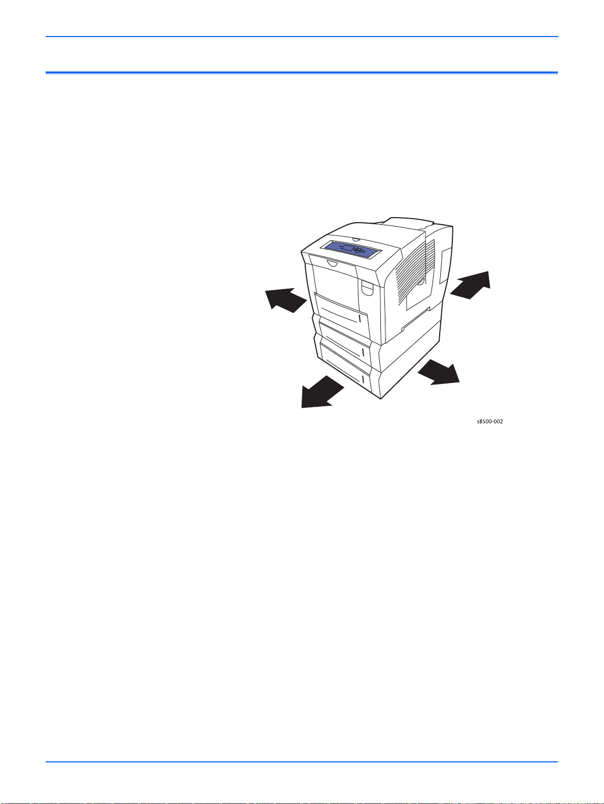
Общая информация
Знакомство с принтером и его общее описание
Руководство по техническому обслуживанию Цветной принтер Phaser
8400/8500/8550/8560 Руководство по техническому обслуживанию
является основным документом, используемым для поиска и устранения
неисправностей, обслуживания и ремонта принтера.
Для гарантированного понимания данного принтера пройдите курс
обучения техническому обслуживанию Цветной принтер Phaser 8400/
8500/8550/8560 Руководство по техническому обслуживанию ,
пользуясь Руководством по самообучению.
Левая
сторона
Задняя
сторона
Передняя
сторона
Правая
сторона
1-2 Цветной принтер Phaser 8400/8500/8550/8560 Руководство по техническому обслуживанию
Page 81

Конфигурации принтера
Карта конфигурации содержит информацию, которая разрешает или
запрещает действие встроенных- функций, как указано в приведенных
ниже таблицах.
Общая информация
Конфигурации принтера Phaser 8400
Функции 8400B 8400BD 8400N 8400DP 8400DX
Максимальная
24 24 24 24 24
скорость печати
Память 128
Mбайт
256
Mбайт
128
Mбайт
256
Mбайт
256
Mбайт
Жесткий диск Нет Нет Опция** Опция** Стандар
тно
Шрифты PostScript 137 137 137 137 137
Шрифты PCL 81 81 81 81 81
Японские шрифты* Нет Нет Опция Опция Опция
Конвейерная
Нет Да Нет Да Да
обработка работ
Автоматическая
двусторонняя печать
Лоток 1 на 100
листов
Лоток 2 на 525
листов
Податчик лотка 3 на
525 листов
Нет Стандар
тно
Станда
ртно
Станда
ртно
Стандар
тно
Стандар
тно
Нет Станда
ртно
Станда
ртно
Станда
ртно
Станда
ртно
Станда
ртно
Стандар
тно
Стандар
тно
Стандар
тно
Опция Опция Опция Опция Стандар
тно
Податчик лотка 4 на
Опция Опция Опция Опция Опция
525 листов
USB, параллельный
порт
Порт Ethernet Нет Нет Станда
* Японские шрифты поставляются для заинтересованных стран по специальной
лицензии.
** Эти функции не обеспечиваются данной конфигурацией. пробная печать,
печать сохраненных работ, защищенная печать и подборка.
Станда
ртно
Стандар
тно
Станда
ртно
ртно
Станда
ртно
Станда
ртно
Стандар
тно
Стандар
тно
Цветной принтер Phaser 8400/8500/8550/8560 Руководство по техническому обслуживанию 1-3
Page 82

Общая информация
Конфигурации принтера Phaser 8500/8550
Функции Phaser 8500N 8500DN 8550DP 8550DT 8550DX
Максимальная
скорость печати
Память 128
24 стр./
мин.
Mбайт
24 стр./
мин.
128
Mбайт
30 стр./
мин.
256
Mбайт
30 стр./
мин.
256
Mбайт
30 стр./
мин.
512
Mбайт
Жесткий диск Опция* Опция* Опция* Опция* Стандар
тно
Шрифты PostScript 137 137 137 137 137
Шрифты PCL 8181818181
Конвейерная
Нет Нет Да Да Да
обработка работ
Автоматическая
Нет Да Да Да Да
двусторонняя
печать
Лоток 1 на 100
листов
Лоток 2 на 525
листов
Податчик лотка 3 на
Станда
ртно
Станда
ртно
Станда
ртно
Станда
ртно
Стандар
тно
Стандар
тно
Станда
ртно
Станда
ртно
Нет Нет Нет Да Да
Стандар
тно
Стандар
тно
525 листов
Податчик лотка 4 на
Нет Нет Нет Нет Да
525 листов
Порт USB Станда
ртно
Станда
ртно
Стандар
тно
Станда
ртно
Стандар
тно
Порт Ethernet Да Да Да Да Да
* Следующие функции включены в принтеры Phaser 8500/8550 с жестким
диском: пробная печать, печать сохраненных работ, защищенная печать,
персональная печать и хранение шрифтов.
Конфигурации принтера Phaser 8560
Функции Phaser 8560N 8560DN 8560DT 8560DX
Максимальная
скорость печати
Память 256 Mбайт 256
30 стр./
мин.
30 стр./
мин.
30 стр./
мин.
30 стр./
мин.
512 Mбайт 512 Mбайт
Mбайт
Жесткий диск Опция* Опция* Опция* Стандартн
о
Шрифты PostScript 137 137 137 137
Шрифты PCL 81 81 81 81
Конвейерная
Нет Нет Да Да
обработка работ
1-4 Цветной принтер Phaser 8400/8500/8550/8560 Руководство по техническому обслуживанию
Page 83

Общая информация
Конфигурации принтера Phaser 8560
Функции Phaser 8560N 8560DN 8560DT 8560DX
Автоматическая
Нет Да Да Да
двусторонняя
печать
Лоток 1 на 100
СтандартноСтандартноСтандартноСтандартн
листов
Лоток 2 на 525
СтандартноСтандартноСтандартноСтандартн
листов
Податчик лотка 3 на
Нет Нет Да Да
525 листов
Податчик лотка 4 на
Нет Нет Нет Да
525 листов
Порт USB СтандартноСтандартноСтандартноСтандартн
Порт Ethernet Да Да Да Да
* Следующие функции включены в принтеры Phaser 8560 с жестким диском:
пробная печать, печать сохраненных работ, защищенная печать, персональная
печать и хранение шрифтов.
о
о
о
Цветной принтер Phaser 8400/8500/8550/8560 Руководство по техническому обслуживанию 1-5
Page 84

Общая информация
Конфигурация панели управления
На панели управления расположены один трехцветный светодиодный
индикатор, дисплей и шесть функциональных кнопок. Кнопки
предназначены для навигации по системе меню на дисплее, выполнения
различных функций и выбора режимов работы принтера.
Светодиодные индикаторы
■ Зеленый = готовность к
печати
■ Мигающий янтарный =
предупреждение
■ Мигающий зеленый = прием,
обработка данных, печать или режим
экономии энергии
■ Мигающий красный = ошибка
1-6 Цветной принтер Phaser 8400/8500/8550/8560 Руководство по техническому обслуживанию
Page 85

Описание режимов панели управления
Общая информация
1
Phaser 8500
READY TO PRINT
Walk-Up Features
Information
Paper Tray Setup
Printer Setup
Troubleshooting
2
1 Светодиодный индикатор
состояния:
Зеленый: Готовность к
печати.
Желтый: Состояние
предупреждения, принтер
продолжает печатать.
Красный: Выполняется
последовательность
запуска или состояние
ошибки.
Мигает: Принтер занят или
прогревается.
5
3
6
4
8
7
s8500-003
5 Кнопка со стрелкой,
направленной вверх
Позволяет перемещаться по
меню вверх.
2 На графический дисплей
выводятся сообщения о
состоянии и меню.
3 Кнопка Отмена
Позволяет отменить
текущую печатную работу.
4 Кнопка Назад
Позволяет вернуться к
предыдущему пункту
меню.
6 Кнопка со стрелкой,
направленной вниз
Позволяет перемещаться по
меню вниз.
7 Кнопка OK
Нажимайте данную кнопку для
того, чтобы подтвердить
выбранную настройку.
8 Кнопка Справка (?)или
Информация
Данная кнопка позволяет
вывести на дисплей справку с
информацией о принтере,
например, о состоянии
принтера
и сообщениях об
ошибках, а также информацию
об обслуживании.
Цветной принтер Phaser 8400/8500/8550/8560 Руководство по техническому обслуживанию 1-7
Page 86

Общая информация
Карты меню
Сочетания кнопок панели управления для быстрого вызова команд
Карта меню пользователя позволяет вам перемещаться по меню панели
управления. Карты меню представлены в справочном разделе данного
Руководства, смотрите стр.A-2.
Чтобы распечатать карту меню:
1. На панели управления выберите Информация, затем нажмите
кнопку OK.
2. Для печати выберите Menu Map (карта меню), затем нажмите кнопку
OK.
Карта меню сервисной диагностики подробно описана в
смотрите “Сервисная диагностика” на стр.4-5.
Режим или меню Сочетание кнопок
главе 4,
Service Tools
Menu (меню
сервисных
средств)
Hidden Service
Menu (скрытое
сервисное
меню)
Сервисная
(внутренняя)
диагностика
Настройка языка
панели
управления
Обход
защищенных
меню
Находясь в любом меню, нажмите и удерживайте
кнопку Стрелка вверх, а затем нажмите кнопку
OK.
Находясь в меню сервисных средств (Service
Too ls ), нажмите и удерживайте кнопку Стрелка
вверх, а затем нажмите кнопку Стрелка вниз.
(Phaser 8400) Удерж ива йте нажатыми кнопки
Назад и Info при включении питания (примерно 30
секунд).
(Phaser 8500/8550/8560) Подождите, пока экран
панели управления станет черным, а затем
нажмите и удерживайте кнопки Назад и Справка
до появления на экране сообщения “Beginning
Service Mode” (запуск сервисного режима).
Нажмите и удерживайте кнопку Отмена , затем
нажмите кнопку Справка.
Нажмите и
нажмите кнопку Назад.
удерживайте кнопку Отмена , затем
Режим подмены
сопел
1-8 Цветной принтер Phaser 8400/8500/8550/8560 Руководство по техническому обслуживанию
(Только Phaser 8400) Для ввода режима подмены
сопел (Jet Substitution Mode) в меню проблем
качества печати (Print Quality Problems):
Находясь в меню проблем качества печати:
нажмите и удерживайте кнопку Стрелка вверх ,
затем нажмите кнопку Назад.
Phaser 8500/8550/8560 содержит режим подмены
сопел в системе главного меню (под Eliminate Light
Stripes [подавление светлых
полос]).
Page 87

Общая информация
Режим
FTTR (быстрый
переход в режим
готовности)
или меню Сочетание кнопок
Принтер переходит в состояние готовности до того,
как температура термических элементов достигнет
рабочих значений. При включении питания, когда
на экране отображается заставка Xerox, нажмите и
отпустите кнопку Стрелка вверх, Затем нажмите
кнопку Стрелка вниз. Если принтер обнаруживает
чернила на барабане, на дисплее отображается
состояние прогрева.
Цветной принтер Phaser 8400/8500/8550/8560 Руководство по техническому обслуживанию 1-9
Page 88

Общая информация
4
1
2
3
4
2
11
Компоненты принтера
В данном разделе показаны основные внешние компоненты принтера,
включая интерфейсы, электронный модуль и внутренние датчики.
Вид спереди
9
8
7
6
5
10
s8500-00
1.Дополнительный податчик
лотка 4 на 525 листов
2.Дополнительный податчик
лотка 3 на 525 листов
3.Лоток 2
4.Лоток 1 на 100 листов (MPT)
5.Панель управления
6.Фиксатор крышки
выходного узла
7.Фиксатор передней дверцы
8.Крышка выходного узла
1
9.Крышка загрузчика чернил/
верхняя крышка
10.Удлинитель выходного
лотка для Legal/A4
11.Крышка интерфейсов
12.Боковая дверца
Вид справа с открытой крышкой интерфейсов
4
1
1-10 Цветной принтер Phaser 8400/8500/8550/8560 Руководство по техническому обслуживанию
3
2
5
6
7
8
s8500-005
1.Комплект технического
обслуживания
2.Лоток для отработанных чернил
3.Гнездо для подключения
электропитания
4.Выключатель питания
5.Параллельный порт (только
серия 8400)
6.Порт USB
7.Карта конфигурации
8.Порт Ethernet 10/100 Base-T
кабеля
Page 89

Вид сзади
06
Общая информация
В задней части принтера расположены основные электронные платы
принтера и блок питания, которые помещены в металлический корпус,
называемый электронным модулем. Задняя панель открывает доступ к
электронному модулю, RAM и NVRAM. На задней панели также
смонтирован жесткий диск принтера.
При установке в принтер нового электронного модуля со старой платы
необходимо перенести следующие компоненты.
2
4
1
3
1
s8500-0
1.
Жесткий диск (дополнительное
устройство)
3.Карту конфигурации
(расположена сбоку под
крышкой интерфейсов)
2.DIMM 1 и DIMM 2 памяти (RAM) 4.NVRAM (карта конфигурации
использует различия NVRAM
разных моделей).
Цветной принтер Phaser 8400/8500/8550/8560 Руководство по техническому обслуживанию 1-11
Page 90

Общая информация
3
2
07
Регулярно заменяемые элементы и расходные материалы
1
2
3
4
1
s8500-0
Регулярно
заменяемые
элементы Расходные материалы
1.Комплект обслуживания
3.Чернила
барабана
2.Лоток для отработанных чернил
Средний срок службы комплекта обслуживания барабана зависит от
емкости этого комплекта. Например, комплект стандартной емкости
позволяет создать 10000 отпечатков, независимо от используемых
цветов. Комплект обслуживания барабана большой емкости для
моделей 8400 и 8550/8560 позволяет отпечатать 30000 страниц при
степени заполнения до 20% и 20000 страниц, когда степень заполнения
превышает 20%. Модели Phaser 8500 не поддерживают комплект
большой емкости для 8550/8560.
1-12 Цветной принтер Phaser 8400/8500/8550/8560 Руководство по техническому обслуживанию
Page 91

Общая информация
П
Регулярность обслуживания: Расходные материалы:
Комплект
обслуживания
барабана
большой емкости
(8400, 8550/8560)
Стандартный
комплект
обслуживания
барабана
Лоток для
отработанных
чернил
* Срок службы расходного материала относится к степени
30000 циклов
(степень заполнения 0
- 20%)
20000 - 30000 циклов
(степень заполнения
20 - 100%)
10000 отпечатков
(8400/8560).
5500 цветных, 10000
черно-белых
отпечатков (8500/
8550).
Опорожняют после
каждых 7 прокачек.
заполнения 5% каждым
цветом на обычной бумаге
формата А4.
Чернила (8400) 1140
отпечатков на
каждый
чернильный
брусок*
(8500/8550/
8560) 1080
отпечатков на
каждый
чернильный
брусок*
римечание
Модели Phaser 8500 поддерживают только комплект обслуживания
барабана стандартной емкости. Модели Phaser 8400 и 8550/8560
поддерживают комплекты стандартной и большой емкости.
Комплекты Phaser 8400 и Phaser 8500/8550/8560 не
взаимозаменяемы.
Цветной принтер Phaser 8400/8500/8550/8560 Руководство по техническому обслуживанию 1-13
Page 92

Общая информация
Характеристики принтера
Габариты и необходимое свободное пространство
Базовый принтер Значение
Ширина:422 мм
Глубина: 514 мм
Высота:368 мм
Вес: 26,8 кг
Дополнительный податчик
бумаги на 525 листов
Ширина:422 мм
Глубина: 514 мм
Высота:132 мм
Вес: 5,4 кг
Минимальное свободное
пространство
Слева и сзади - 102 мм Необходимо для вентиляции.
Справа - 394 мм Необходимо для доступа к комплекту
Спереди - неограниченно Необходимо для доступа к лоткам и
Сверху - 559 мм (только для
базового принтера)
Снизу - не должно быть
посторонних материалов
между несущей
поверхностью и принтером
Значение
Дополнительная информация
обслуживания, лотку для отработанных
чернил, а также для вентиляции.
устранения застреваний.
Необходимо для загрузки чернил и
устранения застреваний.
Необходимо для вентиляции.
Минимальная ширина
установки - 711 мм
1-14 Цветной принтер Phaser 8400/8500/8550/8560 Руководство по техническому обслуживанию
Принтер требуется размещать под
углом для извлечения лотка для
отработанных чернил.
Page 93

П
Базовый принтер Значение
Общая информация
10 см
20 см
56 см
10см
40 см
60 см
60 см
90 см
s8500-141
римечание
Убедитесь, что принтер установлен на устойчивой невибрирующей
поверхности. Посоветуйте пользователю соблюдать осторожность и
не встряхивать принтер при загрузке материала для печати или при
закрывании передней дверцы. Во время работы чернила
расплавляются и могут вытечь из резервуара печатающей головки, и
привести к появлению дефектов печати.
Цветной принтер Phaser 8400/8500/8550/8560 Руководство по техническому обслуживанию 1-15
Page 94

Общая информация
Функциональные характеристики
Характеристика Описание
Процесс печати Твердые чернила
Носитель цвета
Рабочие режимы
и разрешение
Максимальная
скорость печати
Время выхода
первого отпечатка
(Letter/A4)
Время прогрева:
Из выключенного
состояния
(холодный старт)
Из режима
экономии энергии
Отличающиеся по форме бруски чернил желтого,
голубого, пурпурного и черного цвета. Для
создания красного, зеленого и синего цветов в
принтере используется субтрактивная система
формирования цветов.
(8400)
Быстрый цвет (300 x 300 точек на дюйм),
Стандартный (300 x 450 точек на дюйм),
Улучшенный (563 x 400 точек на дюйм), Высокое
разрешение/фото (525 x 2400)
(8500/8550/8560)
Быстрый цвет (225 x 400 точек на дюйм),
Стандартный (300 x 450 точек на дюйм),
Улучшенный (525 x 400 точек на дюйм), Высокое
разрешение/фото (525 x 2400)
24 страниц в минуту (серии 8400 и 8500)
30 страниц в минуту (серия 8550)
Приблизительно 6 секунд
12 минут (8400), 15 минут (8500/8550/8560)
4 минуты
Электрические характеристики
Характеристика Значение
115 В 230
Напряжение
электрической
сети
Частота
электрической
сети
1-16 Цветной принтер Phaser 8400/8500/8550/8560 Руководство по техническому обслуживанию
90 - 140 В 180 -264 В
47 ~ 63 Гц 47 ~ 63 Гц
В
Page 95

Характеристика Значение
115 В 230 В
Общая информация
Потребляемая
мощность
Energy Star® 43 Вт 43 Вт
1250 Вт (пиковая) - 1000
(типовая)
180 Вт (режим
ожидания)
230 Вт (средняя при
печати)
Характеристики окружающей среды
Номинальные условия эксплуатации
Температура 10º - 32º C (50º - 90º F)
при работе
20º - 25º C (68º - 77º F)
для наилучшего качества
Влажность относительная влажность 10% - 80% при
отсутствии конденсации
1250 Вт (пиковая) 1000
(типовая)
180 Вт (режим
ожидания)
230 Вт (средняя при
печати)
Цветной принтер Phaser 8400/8500/8550/8560 Руководство по техническому обслуживанию 1-17
Page 96

Общая информация
Характеристики материалов для печати и лотков
Формат
бумаги
Letter (8,5 x
11 ") или
A4 (210 x
297 мм)
Тип
бумаги
Обычная
бумага
или
бланки
Прозрачн
ые пленки
Карточки
Плотность бумаги/тип
материала для печати
60 - 120 г/м
121 - 220 г/м
2
(16 - 32 lb. Bond)
2
(32 - 59 lb.
Bond)
Пленки для твердых чернил
Phaser
2
100 - 120 г/м
(37 - 44 lb.
Bond)
121 - 220 г/м
2
(44 - 80 lb.
Bond)
Наклейки Наклейки для цветной печати
Phaser
Специаль
ные
материал
ы
Визитные карточки для
твердых чернил Phaser
Фотобумага высокого
разрешения для твердых
чернил Phaser
Открытки Phaser Premium
Postcards
Любой лоток
Только лоток 1
l
l
l
l l
l
l
l
l l
l l
l l
l l
Двусторонняя (дуплексная) печать
Только односторонняя (симплексная) печать
l
l
Стойкая к атмосферным
l l
воздействиям бумага Phaser
Брошюры тройной
l l
фальцовки Phaser
Legal (8,5 x
60 - 120 г/м
2
(16 - 32 lb. Bond)
l l
14 ")
1-18 Цветной принтер Phaser 8400/8500/8550/8560 Руководство по техническому обслуживанию
Page 97

Общая информация
Формат
бумаги
Executive
(7,25 x 10,5 ")
или
A5 (148 x
210 мм)
Statement
(5,5 x 8,5 ")
US Folio (8,5
x 13 ")
A6 (105 x
148 мм)
В5 ISO (176 x
250 мм)
B5 JIS (182 x
257 мм)
Каталожные
карточки
(76,2 x
127 мм)
Тип
бумаги
Плотность бумаги/тип
материала для печати
60 - 120 г/м
121 - 220 г/м
2
(16 - 32 lb. Bond)
2
(32 - 59 lb.
Bond)
60 - 120 г/м
60 - 120 г/м
60 - 120 г/м
60 - 120 г/м
60 - 120 г/м
2
(16 - 32 lb. Bond)
2
(16 - 32 lb. Bond)
2
(16 - 32 lb. Bond)
2
(16 - 32 lb. Bond)
2
(16 - 32 lb. Bond)
Любой лоток
l
l
l l
l l
l l
l l
l l
l l
Только лоток 1
Двусторонняя (дуплексная) печать
Только односторонняя (симплексная) печать
l
l
НестандартныйПРИМЕЧАНИЕ Печатайте на материалах
нестандартного формата только при
подаче из лотка 1.
Максимум: 216 мм (ширина) x
l ll
355 мм (длина)
Минимум: 75 мм (ширина) x
l l
127 мм (длина)
Минимум: 139,7 мм (ширина)
l l
x 210 мм (длина)
Цветной принтер Phaser 8400/8500/8550/8560 Руководство по техническому обслуживанию 1-19
Page 98

Общая информация
Формат
бумаги
Конверты Любой
ПРИМЕЧАНИЕ При печати конвертов иногда могут появиться
морщины и тиснение. Информацию о том, как минимизировать
эти дефекты, вы можете найти в разделе "Печать" документации
пользователя на CD-ROM.
ПРИМЕЧАНИЕ Двустороннюю печать можно выполнять на бумаге
шириной более 139,7 мм и длиной более 210,82 мм.
Тип
бумаги
лоток
Только
лоток 1
Плотность бумаги/тип
материала для печати
#10 Commercial (105 x 240
мм)
DL (110 x 220 мм)
C5 (162 x 229 мм)
#5-1/2 (Baronial 111 x 146 мм)
#6-3/4 (92 x 165 мм)
Monarch (98 x 190 мм)
Брошюра (152 x 229 мм)
A7 (133 x 184 мм)
Choukei 3 Gou (120 x 235 мм)
Choukei 4 Gou (90 x 205 мм)
Любой лоток
Только лоток 1
l
l
l
l
l
l
l
l
l
l
Двусторонняя (дуплексная) печать
Только односторонняя (симплексная) печать
l
l
l
l
l
l
l
l
l
l
1-20 Цветной принтер Phaser 8400/8500/8550/8560 Руководство по техническому обслуживанию
Page 99

Принципы работы
В этой главе…
■ Основные подсистемы принтера
■ Процесс печати
■ Самообслуживание принтера
■ Индивидуальные параметры карты конфигурации
Глава
Page 100

Принципы работы
Основные подсистемы принтера
Система переноса
Преднагрев и
устранение
перекоса
бумаги
Барабан
Комплект
обслуживания
барабана
Печатающая
головка
Лоток для
отработанных
чернил
Узел
протирки
Загрузчик чернил
Электронный
модуль
Жесткий диск
Карта
конфигурации
Усилитель Wave Amp
s8500-008
Обзор подсистем принтера
Принтер имеет восемь основных подсистем, которые описаны в данной
главе.
■ Модуль управления переносом
■ Привод транспортировки бумаги
■ Загрузчик чернил
■ Печатающая головка
■ Комплект обслуживания барабана
■ Система прокачки
■ Узел барабана и узел переноса
■ Электронный модуль
Модуль управления переносом: Передает крутящий момент на два
кулачковых вала. Один кулачковый вал управляет прижимом ролика
переноса, другой - кулачковый вал обслуживания барабана - приводит в
действие комплект обслуживания барабана и систему отклонения
печатающей головки.
2-2 Цветной принтер Phaser 8400/8500/8550/8560 Руководство по техническому обслуживанию
 Loading...