

Page 1
Version 1.0
Technical Product Training
Phaser
8550/8500/8400
Solid Ink Printers
Page 2

Product Training CD-ROM
The Product Training CD-ROM provides multimedia lessons and videos
for the Phaser 8550, Phaser 8500 and Phaser 8400 printers.
Self-Study Guide
The Self-Study Guide provides key lessons and exercises for product
Overview, Setup, Care, and Service. To complete the training, you must
complete the Self-Study Guide lessons and the multimedia lessons on the
CD-ROM, as well as the prerequisites.
Testing
Prepare for the Online Test by completing the Self-Checks. Then, visit
the Testing Center to complete your training.
< www.xerox.com/office/testing >
Continuing Support
The Resources section of the training CD-ROM contains useful printer
documentation and supplemental training materials. To obtain the most
current updates, tips, and bulletins, visit the knowledge base and the
Partner Resource Site. To check for updates to the training materials,
visit the Training Updates Site.
< www.xerox.com/support >
< www.xerox.com/office/partners >
< www.xerox.com/office/training >
Prerequisites
Printing Basics
(Waived with certification on another Phaser printer)
Solid-ink Basics
(Waived with certification on the Phaser 840, 850, 860, or 8200 printer,
or the WorkCentre C2424 copier-printer)
Contact Product Training & Information
support.training@office.xerox.com
(503) 685-4400 (North America)
Page 3

To start your training:
Refer to the Introduction section of the Self-Study Guide for instructions to complete the training.
1.
2. Insert the CD-ROM into the CD-ROM drive of a PC running Windows® 95, 98, Me, 2000, NT, or XP.
3. If the program does not auto-launch, browse to the Files folder, then run START.exe.
Product Training CD-ROM
Minimum System Requirements:
Pentium II 233 MHz Processor
Pentium II 400 MHz Processor ( Recommended )
Windows® 95, 98, Me, 2000, NT, or XP
64 MB RAM
6x CD-ROM Drive
16-bit Sound Card
800 x 600 Monitor with 16-bit Color
Minimum Software Requirements:
Adobe® Reader® ( Included on training CD-ROM )
Web Browser ( Internet Explorer 5.X or later recommended )
Page 4

Page 5

Phaser 8550, 8500, & 8400 Service Self-Study Guide
TABLE OF CONTENTS
INTRODUCTION
Training Program Overview ............................................... 1
Training CD-ROM........................................................ 1
Self-Study Guide........................................................... 1
Prerequisite Courses ..................................................... 1
Training Kit Contents ......................................................... 2
Running the Training CD-ROM......................................... 2
Adobe® Reader®........................................................... 2
Supported Operating Systems....................................... 3
Completing the Training..................................................... 3
Phaser 8550, 8500, & 8400 Course Map...................... 4
Required Materials.............................................................. 4
Online Testing Center......................................................... 5
If You Need Help................................................................ 6
How to Contact Xerox Product Training & Information.... 6
OVERVIEW SECTION
Overview Objectives........................................................... 7
Configurations .................................................................... 7
Options & Upgrades ......................................................... 12
Features............................................................................. 14
Phaser 8500 and 8550 Printers...................................... 7
Phaser 8400 Printers ..................................................... 9
Primary Differences.................................................... 10
Memory....................................................................... 12
525-Sheet Feeder ........................................................ 13
Hard Drive (Productivity Kit)..................................... 13
Configuration Upgrades.............................................. 13
Speed & Quality.......................................................... 14
Phaser 8500 and 8550 Print-Quality Modes............... 15
Phaser 8400 Print-Quality Modes............................... 15
Factors That Reduce Print Speed................................ 16
Print Grayscale Images ............................................... 16
Run Black Mode ......................................................... 16
Speed & Quality Review Exercise.............................. 17
Walk-Up Features ....................................................... 17
Media Support................................................................... 19
Tray 1 (MPT).............................................................. 19
PHASER 8550, 8500, & 8400 TABLE OF CONTENTS
Version 1.0
page i
Page 6

SETUP SECTION
525-Sheet Tray (Trays 2, 3, & 4) ............................... 20
Media Support Review Exercise................................ 20
Documentation & Software.............................................. 21
User Manuals & Guides ............................................. 22
Videos......................................................................... 22
Embedded Pages ........................................................ 23
Printer Drivers & Utilities.......................................... 23
Color Adjustment Sliders........................................... 25
Xerox Support Centre................................................. 26
Your Next Step................................................................. 26
Setup Objectives............................................................... 27
Setting up the Printer........................................................ 27
Setup Review Exercise............................................... 28
Load Paper........................................................................ 28
Guidelines................................................................... 29
Loading Tray 1 (MPT) ............................................... 29
Loading Trays 2, 3, & 4 ............................................. 31
Loading Paper Review Exercise................................. 31
Configure Control Panel................................................... 32
Menus ......................................................................... 32
Shortcuts..................................................................... 32
Control Panel Defaults ............................................... 33
Control Panel Lab....................................................... 33
Test Ports.......................................................................... 33
Network Diagnostics .................................................. 34
Test Windows Ethernet Port (Alternate Procedure)... 34
Test Parallel Port ........................................................ 35
Test Macintosh USB Port........................................... 36
Test Macintosh Ethernet Port..................................... 38
Printing Lab...................................................................... 39
Install Software .......................................................... 39
Print Jobs.................................................................... 40
Use the Xerox Support Centre.................................... 40
Install Upgrades................................................................ 41
General Instructions ................................................... 41
Memory Upgrade ....................................................... 42
Hard Drive (Productivity Kit) Upgrade...................... 42
Configuration Upgrades ............................................. 43
Your Next Step................................................................. 43
page ii
PHASER 8550, 8500, & 8400 TABLE OF CONTENTS
Version 1.0
Page 7

CARE SECTION
Care Objectives................................................................. 45
Paper Jams ........................................................................ 45
Resources.................................................................... 45
General Techniques .................................................... 46
Jams Behind Front Cover ........................................... 47
Jams Inside Preheater.................................................. 47
Exit Jams..................................................................... 48
Jams At Trays ............................................................. 48
Supplies............................................................................. 49
Ink Sticks .................................................................... 49
Maintenance Kits ........................................................ 52
Troubleshooting Exercise ........................................... 54
Cleaning............................................................................ 56
Eliminate Light Stripes ............................................... 56
Remove Print Smears.................................................. 61
Clean Components Manually...................................... 62
Cleaning Review Exercise.......................................... 63
Replace Parts..................................................................... 64
Feed Roller Kit............................................................ 64
Front Door and Tray Kit ............................................. 65
Replace Parts Lab ....................................................... 65
Moving The Printer........................................................... 66
Moving and Shipment Review Exercise..................... 66
Your Next Step ................................................................. 66
SERVICE SECTION
Service Objectives ............................................................ 67
Troubleshooting................................................................ 68
Service Tools .............................................................. 68
Error Codes................................................................. 68
Print Quality................................................................ 71
Electronics Troubleshooting....................................... 73
Printhead Troubleshooting Checklist Exercise........... 74
Service Precautions........................................................... 75
Hazards ....................................................................... 75
Customer Environment............................................... 76
Handling Parts............................................................. 76
Grounding ................................................................... 77
Homing Components .................................................. 78
PHASER 8550, 8500, & 8400 TABLE OF CONTENTS
Version 1.0
page iii
Page 8

APPENDIX
Parts Replacement Tips.................................................... 79
Exterior Covers .......................................................... 79
Ink Loader Assembly ................................................. 81
Stripper Carriage Assembly ....................................... 82
Printhead..................................................................... 82
Electronics Module .................................................... 84
X-Axis Motor Assembly ............................................ 84
Y-Axis Drive Motor Assembly .................................. 84
Exit Assembly ............................................................ 85
Printhead Wiper Assembly......................................... 85
Drum Assembly.......................................................... 86
Lubrication ................................................................. 87
Tightening Screws...................................................... 87
Disassembly Lab ........................................................ 88
Your Next Step................................................................. 88
Answers to Overview Exercises....................................... 89
Speed & Quality Review Exercise............................. 89
Media Support Review Exercise................................ 89
Answers to Setup Exercises ............................................. 90
Setup Review Exercise............................................... 90
Loading Paper Review Exercise................................. 90
Answers to Care Exercises............................................... 90
Troubleshooting Exercise........................................... 90
Cleaning Review Exercise.......................................... 91
Moving and Shipment Review Exercise .................... 91
Answers to Service Exercises........................................... 92
Error Codes Review Exercise..................................... 92
Print Quality Review Exercise ................................... 92
Printhead Troubleshooting Checklist Exercise .......... 92
Homing Components Exercise................................... 93
Tightening Screws Review Exercise.......................... 93
Resources.......................................................................... 94
Links........................................................................... 94
Contact Information ................................................... 94
Glossary of Acronyms................................................ 94
page iv
PHASER 8550, 8500, & 8400 TABLE OF CONTENTS
Version 1.0
Page 9
Phaser 8550, 8500, & 8400 Service Self-Study Guide
INTRODUCTION
Prerequisites
❑ Printing Basics
❑ Solid-ink Basics
Printer Requirements
❑ A Phaser 8550, 8500, or
8400 printer is optional
for this training
Time To Complete
❑ Reading: 2.5 hours
❑ Video run time: 3 hours
❑ Exercises: 2 hours
❑ Optional labs: 5 hours
❑ Self-Checks: 45 min.
❑ Online test: 45 min.
Online Tests
An online test must be taken
to complete the Phaser 8550,
8500, & 8400 Service
Training. Refer to “Online
Testing Center” on page 5 for
details.
Resources
❑ Phaser 8550, 8500, &
8400 Product Training
CD-ROM
❑ Phaser 8400/8500/8550
Service Manual
❑ Testing Center:
www.xerox.com/
office/testing
❑ Partner Resource Site:
www.xerox.com/
office/partners
❑ Knowledge Base:
www.xerox.com/support
❑ Training Update Site:
See “If You Need Help”
on page 6.
Training Program Overview
The Phaser 8550, 8500, & 8400 training program is a self-paced course for service
technicians. It is divided into four sections called Overview, Setup, Care, and Service.
The course consists of the Phaser 8550, 8500, & 8400 Self-Study Guide, the
Phaser 8550, 8500, & 8400 Product Training CD-ROM, and two prerequisite courses.
Complete this course for certification on the Phaser 8550, 8500, and
8400 printers.
Training CD-ROM
The training CD-ROM provides multimedia training lessons and self-checks to
prepare for the certification test. The Resources section of the training CD-ROM
contains electronic versions of the printer documentation including manuals,
instruction sheets, and examples of the most important embedded pages. Web links on
the CD-ROM provide access to support information and the online testing center.
Self-Study Guide
The Self-Study Guide provides instructions for completing the training and many of
the lessons you will need to pass the certification test. It also provides exercises that
can be completed if you do not have access to the printer, and hands-on labs for use
when a printer is available. A PDF version of this Self-Study Guide is available from
the training CD-ROM’s Resources section.
Prerequisite Courses
The Printing Basics and Solid-ink Basics prerequisite courses must be completed
before you begin the Phaser 8550, 8500, and 8400 training program. The prerequisites
are waived if you have previously been certified on other Xerox Phaser printers, as
shown below:
■ Printing Basics
Waived with certification on another Phaser printer
■ Solid-ink Basics
Waived with certification on the Phaser 840, 850, 860, or 8200 printer, or
the WorkCentre C2424 copier-printer
PHASER 8550, 8500, & 8400 INTRODUCTION
Version 1.0
If you are already certified on the Phaser 840, 850, 860, or 8200
color printer, or the WorkCentre C2424 copier-printer, you are
ready to begin this training.
page 1
Page 10
Training Kit Contents
The following items are provided in the Phaser 8550, 8500, & 8400 Service Training Kit:
■ Phaser 8550, 8500, & 8400 Self-Study Guide
■ Phaser 8550, 8500, & 8400 Product Training CD-ROM
■ Phaser 8500/8550 Software and Documentation CD-ROM
■ Phaser 8500 and 8550 Network Connectivity Sheet
■ Phaser 8400/8500/8550 Service Manual (not included in Help Desk kits)
Use the Self-Study Guide, training CD-ROM, and Service Manual to complete this training. Use the
Software and Documentation CD-ROM to install printer drivers and other system software. Refer to the
Network Connectivity Sheet for the supported operating systems, network topologies, and protocols.
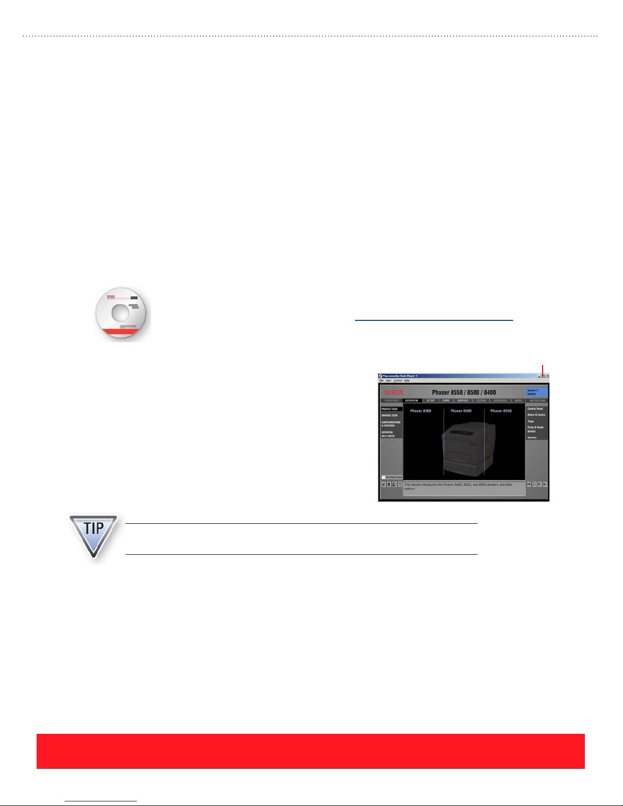
Running the Training CD-ROM
The Phaser 8550, 8500, & 8400 Training CD-ROM was created using Macromedia Flash. If
the training program fails to run as expected, you may need to download and install the latest
version of the Macromedia Flash Player. Use www.macromedia.com/downloads/
the player.
to access
Adobe
The training CD-ROM is designed to auto-launch. If
your computer does not automatically start the training
Restore Down Button
CD-ROM, follow the steps below:
1. Insert the Phaser 8550, 8500, & 8400 Product
Training CD-ROM into your computer.
2. Navigate the contents of the CD-ROM and
double-click Start.exe.
The training launches in full-screen view. Press <Esc>
on your keyboard to view it in a smaller window, or use
the “Restore Down” button shown to the right.
Viewing the program in a smaller window allows you to view reference
documents or switch between the training and other programs on your computer.
®
Reader
®
Adobe Reader is required to view the PDF documents contained in the Resources section. If Adobe Reader is
not installed, use the following procedure to install it on your computer:
1. Insert the Phaser 8550, 8500, & 8400 Product Training CD-ROM.
2. Browse to the Files/Installers folder.
3. Open the file “AdbeRdr70_enu_full.exe” and follow the instructions to install Adobe
page 2
®
Reader®.
PHASER 8550, 8500, & 8400 INTRODUCTION
Version 1.0
Page 11
Supported Operating Systems
The following operating systems may be used to run the training program:
■ Windows
■ Windows
®
95, Windows 98, Windows Millennium Edition (Me)
®
NT 4.0, Windows 2000, Windows XP, Windows Server 2003
Completing the Training
Complete the following tasks to become certified on the Phaser 8550, 8500, and 8400 printers. Refer to the
“Phaser 8550, 8500, & 8400 Course Map” on page 4 for a visual guide of the training topics.
You will be tested on material located on the training CD-ROM and in the
Self-Study Guide.
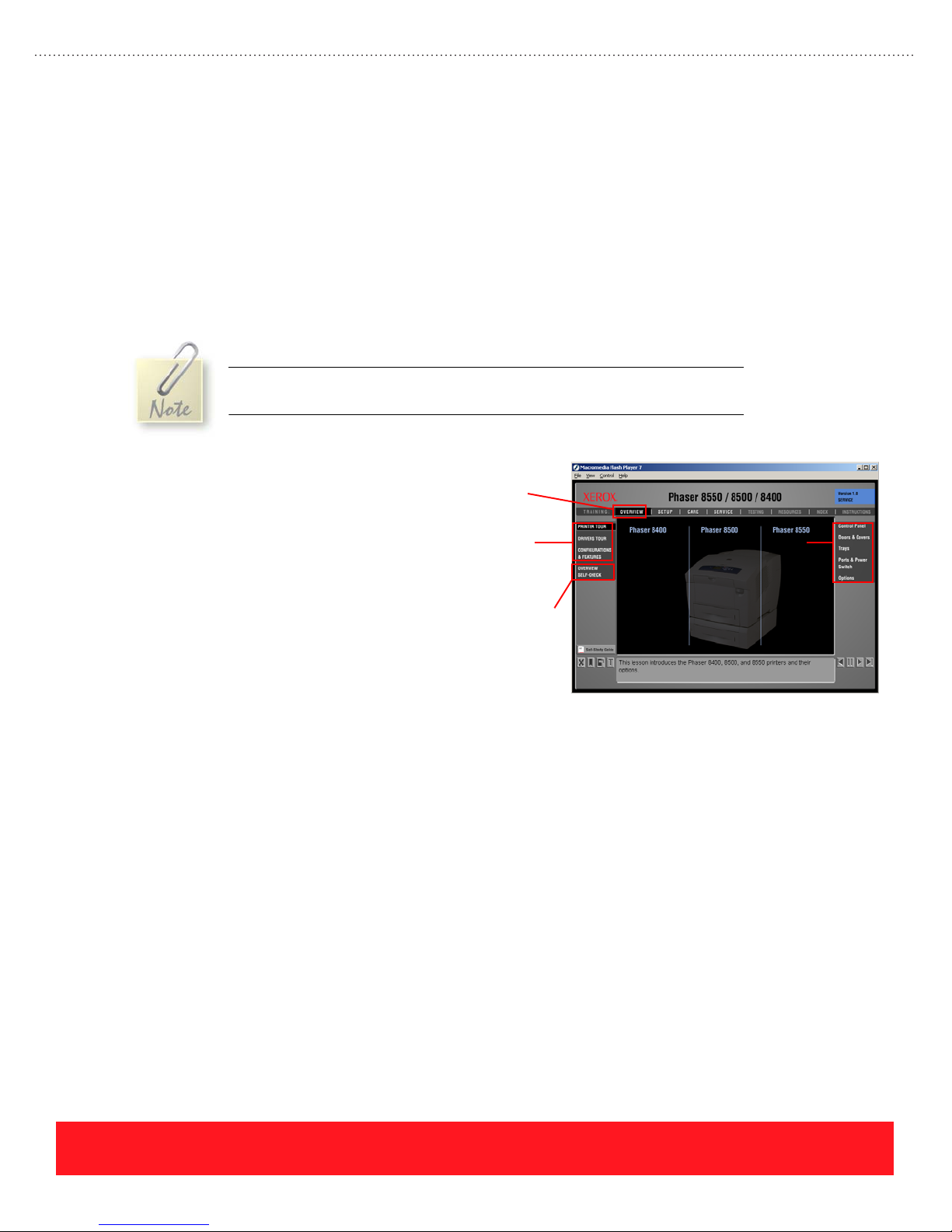
1. Insert the training CD-ROM to
launch the training program.
2. Select “Overview” and complete
each training lesson on the left
side of the screen. Many lessons
also have subtopics that are listed
on the right side of the screen.
3. Turn to “Overview Objectives” on
page 7 of the Self-Study Guide (SSG)
and complete the Overview section.
Overview
Section
Training
Lessons
Self-Check
Subtopics
4. Complete the Overview Self-Check
located on the training CD-ROM.
5. Complete the Setup section of the training course:
a. Complete the Setup multimedia lessons located on the training CD-ROM.
b. Turn to “Setup Objectives” on page 27 and complete the Setup section of the SSG.
c. Return to the training CD-ROM and complete the Setup Self-Check.
6. Complete the Care section of the training course:
a. Complete the Care multimedia lessons located on the training CD-ROM.
b. Turn to “Care Objectives” on page 45 and complete the Care section of the SSG.
c. Return to the training CD-ROM and complete the Care Self-Check.
7. Complete the Service section of the training course:
a. Complete the Service multimedia lessons located on the training CD-ROM.
b. Turn to “Service Objectives” on page 67 and complete the Service section of the SSG.
c. Return to the training CD-ROM and complete the Service Self-Check.
8. Complete the Phaser 8400/8500/8550 online test.
PHASER 8550, 8500, & 8400 INTRODUCTION
Version 1.0
page 3
Page 12
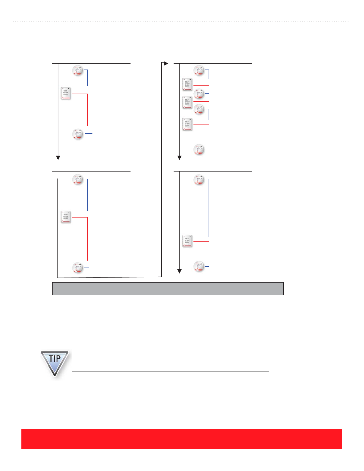
Phaser 8550, 8500, & 8400 Course Map
Overview
Setup
Printer Tour
1.
Drivers Tour
2.
Configurations & Features
3.
Configurations
4.
Options & Upgrades
5.
Features
6.
Media Support
7.
Documentation & Software
8.
Overview Self-Check
9.
Printer Installation
1.
Power-On Process
2.
Test Ports
3.
Custom Size Jobs
4.
Advanced Setup Procedures
5.
Setup the Printer
6.
Load Paper
7.
Configure Control Panel
8.
Test Ports
9.
Printing Lab
10.
Install Upgrades
11.
Setup Self-Check
12.
Care
Service
Print Process
1.
Paper Jams
2.
3.
Paper Jams
Supplies
4.
5.
Supplies
Troubleshooting
6.
User Maintenance
7.
8.
Cleaning
9.
Replace Parts
10.
Moving the Printer
Care Self-Check
11.
Theory Of Operation
1.
Printhead Procedures
2.
Media Drive Procedures
3.
Process Drive Procedures
4.
Transfix Load Module Procedures
5.
Replacement Videos
6.
Troubleshooting
7.
Precautions & Tips
8.
Troubleshooting
9.
Service Precautions
10.
Parts Replacement Tips
11.
Service Self-Check
12.
Required Materials
A printer is not required to complete the certification process. However, this Self-Study Guide includes labs
that provide hands-on activities to enhance understanding when a printer is available. Use the following
manuals, software, and equipment to complete this training course:
A printer is not required to complete the certification process.
page 4
Online Test
PHASER 8550, 8500, & 8400 INTRODUCTION
Version 1.0
Page 13
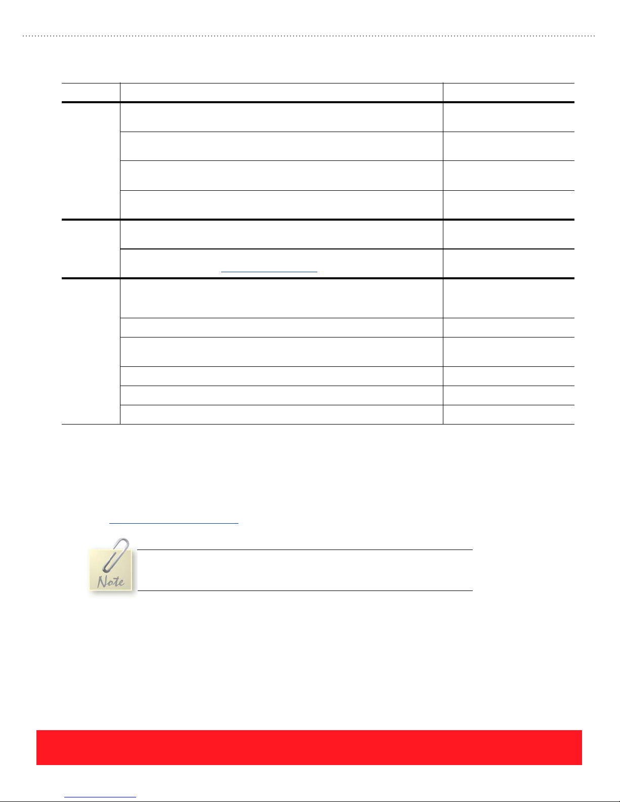
Item Minimum Requirements Example
Manuals Xerox Phaser 8500/8550 User Guide (available from the Resources section
Software Internet Explorer
Equipment Minimum workstation requirements: Pentium II 233 MHz CPU, Windows
of the training CD-ROM)
Xerox Phaser 8500/8550 Quick Reference Guide (available from the
Resources section of the training CD-ROM)
Xerox Phaser 8500/8550 Setup Guide (available from the Resources section
of the training CD-ROM)
Xerox Phaser 8400/8500/8550 Service Manual (available from the Resources
section of the training CD-ROM)
®
5.5, Macromedia Flash 6.0® ActiveX Control/Plug-in,
Adobe Reader
Phaser 8500/8550 Software and Documentation CD-ROM
(download drivers from www.xerox.com/support
9x/Me/NT/2000/XP, 64 MB RAM, 6x CD-ROM drive, 16-bit sound card, 800 x
600 monitor with 16-bit color
Xerox Phaser 8550, 8500, or 8400 printer (optional) Xerox Phaser 8550DP
DB25-to-Centronics parallel cable (for Phaser 8400 printers only),
USB 2.0 cable, or Category 5 UTP Ethernet cable (optional)
Grease, Reolube 768 (optional) Xerox P/N 006799700
Torque Screwdriver (optional) Xerox P/N 003082700
®
)
®
Xerox P/N 721P58550
Xerox P/N 063347500
Desktop or laptop PC with
400 MHz Pentium II Processor (or faster) recommended
Standard bench tools (optional)
Online Testing Center
The last step in the training process is an online test. Use the Self-Checks provided on the training CD-ROM
to prepare for the online test. You should take the online test immediately after completing the Self-Study
Guide, multimedia lessons, and the Self-Checks to complete your training. To access the Testing Center,
launch a web browser such as Microsoft
www.xerox.com/office/testing
An account name and password are required to access the Testing Center. If
you do not already have these, they are included in your welcome letter,
which is mailed separately from this training package.
®
Internet Explorer® and enter the following URL:
PHASER 8550, 8500, & 8400 INTRODUCTION
Version 1.0
page 5
Page 14
During the test, only one question appears on the screen. You cannot jump ahead to see other questions, or
scroll back to change answers. Certain questions that cover key information may trigger an automatic test
failure if you answer them incorrectly. Manuals that are normally available (for example, the Service Manual)
may be used as resources when taking the test. Test results are provided immediately. When a test failure
occurs, review topics are suggested based on the questions missed. If you fail a test three times, you must
contact a Xerox Product Training & Information representative at (503) 685-4400 (North America only).
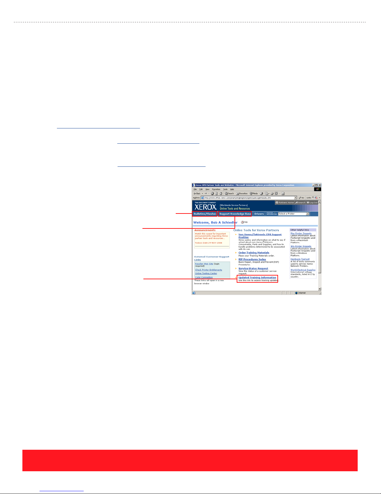
If You Need Help
To obtain the most current updates, tips, and bulletins, visit the Partner Resources site at
www.xerox.com/office/partners, or the training update site at one of these locations:
Internet Access: www.xerox.com/office/training
■ Requires login (user name and password)
Intranet Access: cpidserv.opbu.xerox.com/training
■ Requires intranet access, located behind Xerox firewall
Service Bulletins & Flashes
Knowledge Base
Training Updates
Certified technicians should use the Updated Training Information link to access updated training and
general reference material. The site includes links to Frequently Asked Questions for training. It also includes
Certification Checklists for all training programs.
How to Contact Xerox Product Training & Information
Xerox wants to help you successfully complete this training course. If you need assistance with any part of
the training, please contact us through the Contact Us link located on the Testing Center web page, or by
using the following email address and telephone number:
■ E-mail: support.training@office.xerox.com
■ Phone: (503) 685-4400 (North America only)
page 6
PHASER 8550, 8500, & 8400 INTRODUCTION
Version 1.0
Page 15
Phaser 8550, 8500, & 8400 Service Self-Study Guide
OVERVIEW SECTION
Prerequisites
❑ Overview section of the
Phaser 8550, 8500, &
8400 Product Training
CD-ROM
Time To Complete
❑ Reading: 30 min.
❑ Video run time: 30 min.
❑ Exercises: 20 min.
Equipment Checklist
❑ Phaser 8500/8550 User
Guide (available from
the Resources section
of the training CD-ROM
❑ Adobe
®
Reader
®
Reference Manuals
Electronic copies of the
product manuals, guides,
and instruction sheets are
located on the training
CD-ROM.
Use the training CD-ROM’s
Resources section to access
the manuals and other
documentation.
Overview Objectives
■ Describe the printer configurations, specifications, and features
■ Identify the supported media types, sizes, and capacities
■ Locate sources of information, such as user documentation and software
Before you begin this section of the Self-Study Guide, you should have already
completed the Overview section of the Phaser 8550, 8500, & 8400 Product Training
CD-ROM. The multimedia topic “Configurations & Features” indicates when to
begin the lessons in the Self-Study Guide.
Complete the Overview multimedia lessons on the training
CD-ROM before you begin this section of the Self-Study Guide.
Configurations
This lesson presents the configurations available for the Phaser 8550,
8500, and 8400 printers. A summary of the primary differences between
the printer models is also included.
Phaser 8500 and 8550 Printers
The Phaser 8500 and 8550 printers are the next generation of solid ink technology,
exclusively from Xerox. The Phaser 8500 and 8550 are actually two printer families
targeting two distinctly separate markets.
■ Phaser 8500 - Phaser 8500 printers are for cost-conscious customers who
require the lowest acquisition costs. There are two configurations in the
Phaser 8500 family, each capable of printing up to 24 pages-per-minute.
The base Phaser 8500N configuration is network-ready and the Phaser
8500DN configuration features automatic two-sided (duplex) printing as
well as networking. Both models are network-ready, but only the Phaser
8500DN model features automatic two-sided printing.
■ Phaser 8550 - The Phaser 8550 family prints up to 30 pages-per-minute. Entry
level Phaser 8550DP printers support networking and automatic two-sided
printing. The Phaser 8550DT configuration includes an additional 525-Sheet
Feeder. The fully-featured Phaser 8550DX configuration includes 512 MB of
RAM, two 525-Sheet Feeders, and the advanced printing features associated
with the hard drive.
PHASER 8550, 8500, & 8400 OVERVIEW SECTION
Version 1.0
page 7
Page 16
All Phaser 8500 and 8550 printers include the following standard features:
■ 600 MHz processor ■ USB 2.0 and Ethernet ports
■ First page out time as low as 5 seconds ■ Automatic color corrections
■ 139 PS and 81 PCL resident fonts ■ Standard 1-year, on-site service warranty
■ Support for PostScript 3 and PCL5c ■ PrintingScout, CentreWare IS,
PhaserSMART, & CentreWare Web
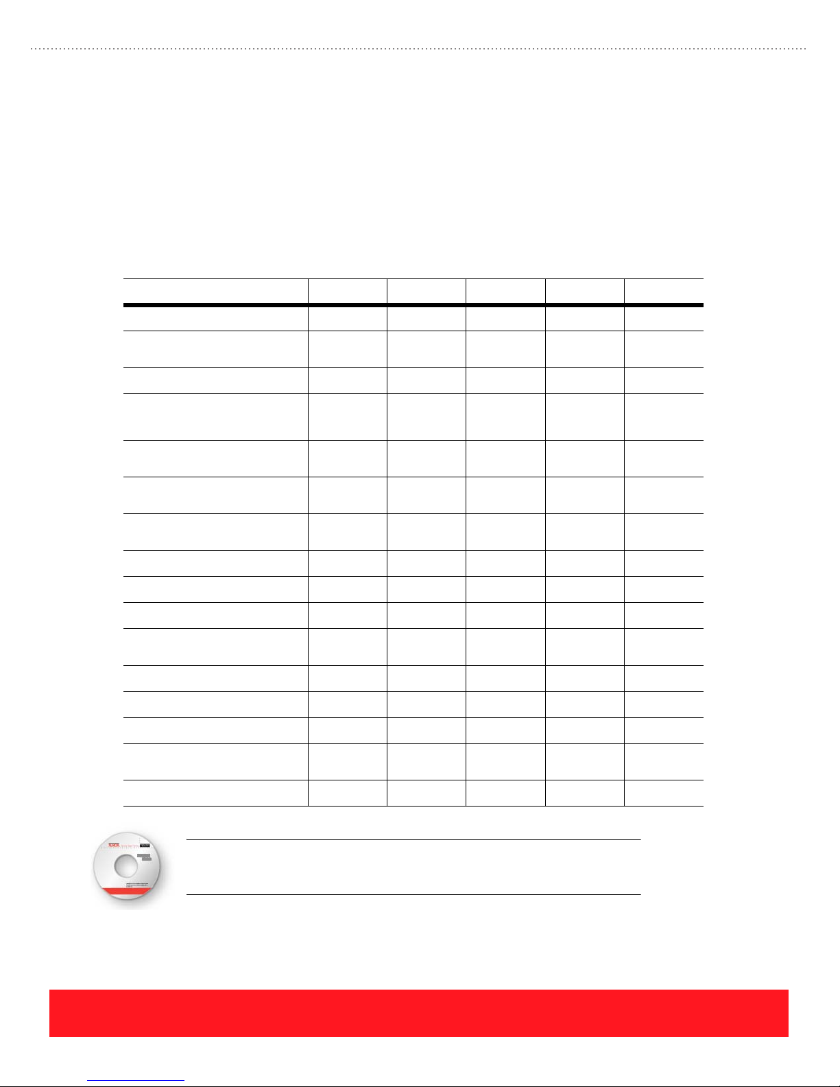
Use the following table to compare the features of each Phaser 8500 and 8550 printer configuration.
Feature 8500N 8500DN 8550DP 8550DT 8550DX
Maximum Print Speed
Minimum First Print Out
Time (FPOT)
Controller
Standard Memory
Maximum
Fast Color & Enhanced Print
Quality Modes
Standard & High Res/Photo
Print Quality Modes
PCL Print Quality Modes
Productivity Kit (Hard Drive)
Automatic 2-Sided Printing
Legal Printing
Connectivity
Pipelining
RAM Collation
24 ppm 24 ppm 30 ppm 30 ppm 30 ppm
6 seconds 6 seconds 5 seconds 5 seconds 5 seconds
600 MHz 600 MHz 600 MHz 600 MHz 600 MHz
128 MB
------------1 GB
128 MB
------------1 GB
256 MB
------------1 GB
256 MB
------------1 GB
512 MB
------------1 GB
33333
No No 333
600 x 300 600 x 300 600 x 300
600 x 600
600 x 300
600 x 600
600 x 300
600 x 600
No Support No Support Optional Optional 3
No 3333
33333
USB &
Ethernet
USB &
Ethernet
USB &
Ethernet
USB &
Ethernet
USB &
Ethernet
No No 333
No No 33No
Disk Collation
Proof/Saved/Secure/
Personal Print
525-Sheet Feeder(s)
An optional multimedia lesson called “Phaser 8500 and 8550 Product Tour” is
available on the training CD-ROM. To access the lesson, select the Resources
section of the training CD-ROM and choose “User Videos”.
page 8
No No Optional Optional 3
No No Optional Optional 3
Optional Optional Optional 1 2
PHASER 8550, 8500, & 8400 OVERVIEW SECTION
Version 1.0
Page 17
Phaser 8400 Printers
The Phaser 8400 can be ordered in four configurations: B, N, DP, and DX. A fifth configuration, the BD, is
available by installing an upgrade to Phaser 8400B printers. Each printer has a common set of standard
features, which include the following:
■ 500 MHz processor ■ Support for PostScript 3 and PCL5c
■ Up to 24 full color pages per minute ■ USB 2.0 and bi-directional parallel ports
■ First page out time as low as 6 seconds ■ Automatic color corrections
■ 137 PS and 81 PCL resident fonts ■ Standard 1-year, depot service warranty
■ Fast Color, Standard, Enhanced, and
High Res/Photo Print Quality Modes
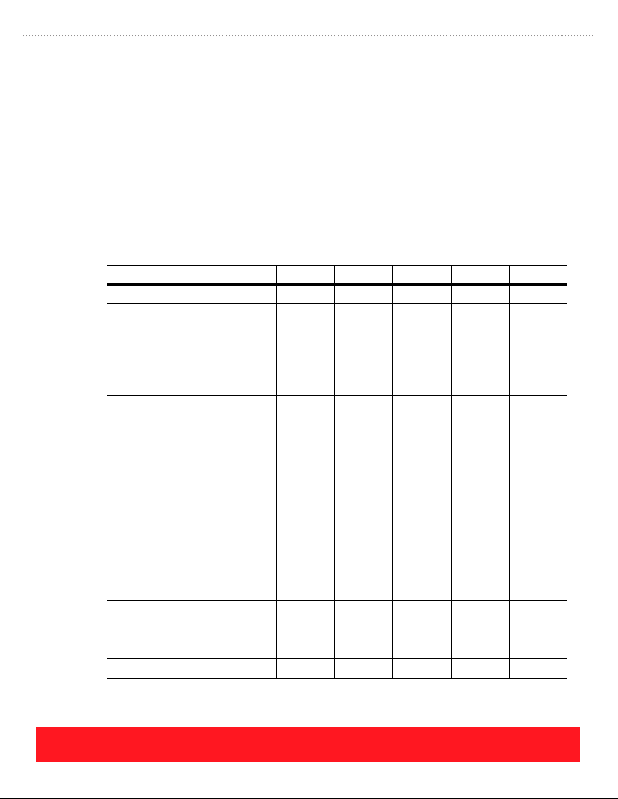
Use the following table to compare the features of each Phaser 8400 printer configuration.
Feature 8400B 8400BD 8400N 8400DP 8400DX
Maximum Print Speed
Standard Memory
Maximum
Fast Color, Standard, Enhanced, &
High Res/Photo Print Quality Modes
PCL Print Quality Modes
Hard Drive
Automatic 2-Sided Printing
Job Pipelining
Legal Printing
Connectivity
PrintingScout, PhaserSMART,
CentreWare IS, & CentreWare Web
Disk Collation
24 ppm 24 ppm 24 ppm 24 ppm 24 ppm
128 MB
------------512 MB
256 MB
------------512 MB
128 MB
------------512 MB
256 MB
------------512 MB
256 MB
------------512 MB
33333
600 x 300
600 x 600
Upgrade
required
Upgrade
required
Upgrade
required
600 x 300
600 x 600
Upgrade
required
3 Upgrade
3 Upgrade
600 x 300
600 x 600
600 x 300
600 x 600
600 x 300
600 x 600
Optional Optional 3
33
required
33
required
33333
Parallel &
USB
Upgrade
required
Upgrade
required
Parallel &
USB
Upgrade
required
Upgrade
required
Parallel,
USB, &
Ethernet
Parallel,
USB, &
Ethernet
Parallel,
USB, &
Ethernet
333
Upgrade
required
Upgrade
required
3
Job Accounting
Proof/Saved/Secure Print
525-Sheet Feeders
PHASER 8550, 8500, & 8400 OVERVIEW SECTION
Version 1.0
Upgrade
required
Upgrade
required
Upgrade
required
Upgrade
required
50 records 500
records
Upgrade
required
Upgrade
required
5000
records
Optional Optional Optional Optional 1
3
page 9
Page 18
Primary Differences
Phaser 8500 and 8550 printers look and function much like Phaser 8400 printers, but physical differences can
be used to identify the Phaser 8500/8550 print engine, supplies, manuals, and printer software CD-ROM.
There are also differences in the network connectivity and hard drive features.
Print Engine
Key differences between the Phaser 8500/8550 and Phaser 8400 print engines include the Control Panel
menus, communication ports, and customer touch points.
■ Control Panel Menus - The Control Panel menus include several new features and usability
improvements. Use the training CD-ROM’s Resources section to view or print Menu Maps for the
Phaser 8400 and Phaser 8500/8550 printers.
■ Communications Ports - Ethernet and USB ports are standard on all Phaser 8500 and 8550
models. A parallel port is not provided. In comparison, all Phaser 8400 printers include parallel
and USB ports. Only the Phaser 8400N, DP, and DX configurations provide an Ethernet port.
■ Customer Touch Points - Most customer touch points are green plastic on Phaser 8400 printers.
On Phaser 8500 and 8550 printers, the same parts are white with green labels. Customers use the
touch points to perform maintenance functions such as clearing jams and replacing supplies.
Printer Supplies
Phaser 8500/8550 supplies are similar to Phaser 8400 supplies but are not interchangeable. Refer to
“Supplies” on page 49 for more information on the ink sticks and Maintenance Kits.
■ Ink Sticks - Phaser 8500/8550 ink sticks have unique shapes and are not interchangeable with
other printers. The same inks are used in Phaser 8500 and 8550 models.
■ Ink Status - When Phaser 8500 and 8550 printers run out of ink, the Control Panel display
indicates which color must be loaded. Phaser 8400 printers indicate when ink is low, but the user
must open the ink loader to visually determine which color is low.
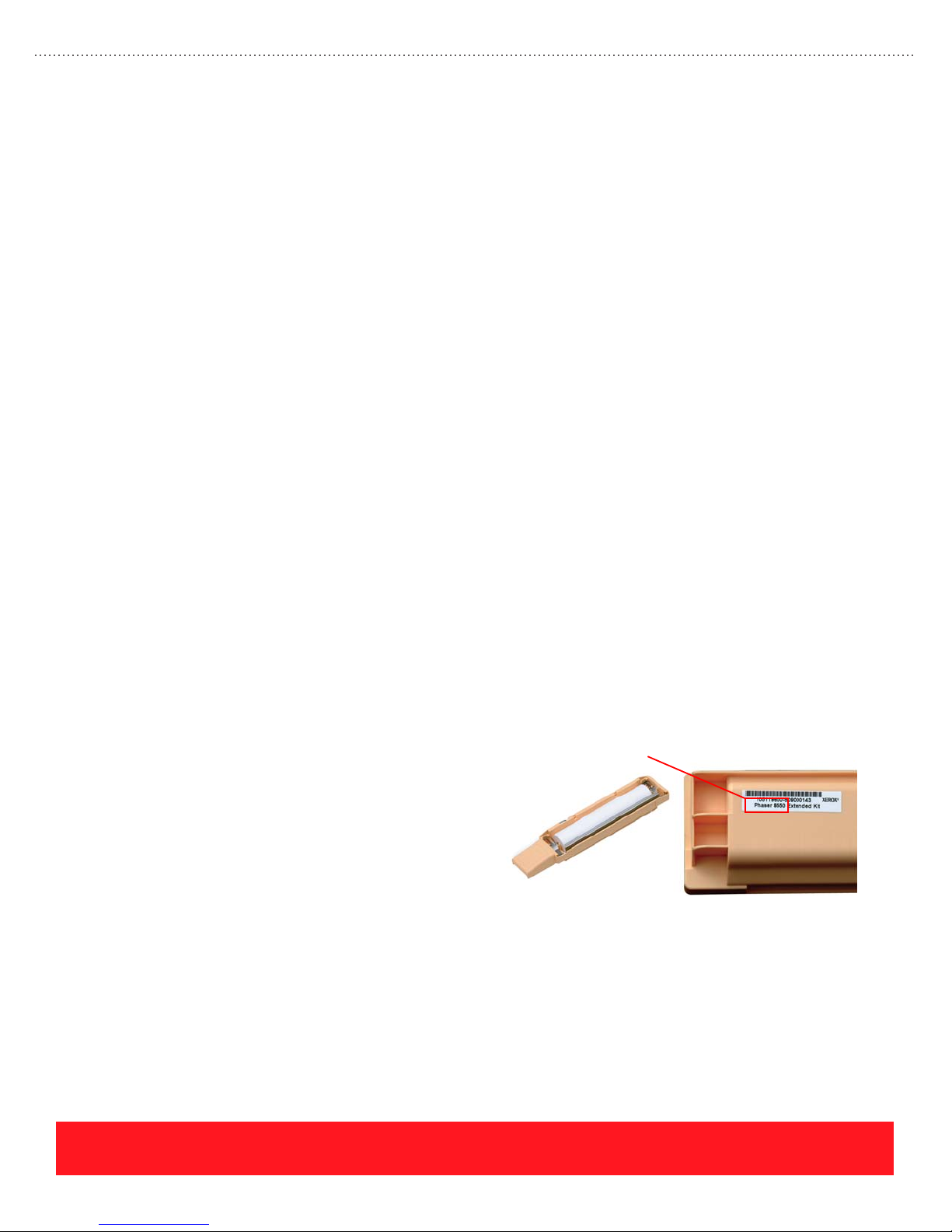
■ Maintenance Kit - Customers can tell
the difference between Phaser 8400 and
Phaser 8500/8550 Maintenance Kits by
Phaser 8500/8550
Printer Model
checking the label on the bottom of the
kit as shown to the right. The label for
Phaser 8500/8550 Maintenance Kits
includes the product type. Phaser 8400
Maintenance Kit labels have no product
identification.
Software & Documentation
Phaser 8400 printers include a User Documentation CD-ROM and a Printer Installer & Utilities CD-ROM.
The Phaser 8500 and 8550 printer software and user documentation is provided on a single Software and
Documentation CD-ROM. Installing the Phaser 8500 and 8550 software also loads a utility called the Xerox
Support Centre. This utility provides access to the user documentation and printer driver settings, online
documentation, and troubleshooting tools. See “Xerox Support Centre” on page 26 for details.
page 10
PHASER 8550, 8500, & 8400 OVERVIEW SECTION
Version 1.0
Page 19
Network Connectivity
Network connectivity is standard for the Phaser 8400N, DP, and DX printers and all Phaser 8500 and 8550
configurations. Each model supports PhaserSMART, PrintingScout, MaiLinX, and the Usage Analysis Tool,
but there are differences in support for network protocols and CentreWare as shown below:
Network Connectivity 8400N, DP, & DX 8500N & DN 8550DP, DT, & DX
Network Protocols TCP/IP, IPX/SPX, & EtherTalk TCP/IP & EtherTalk TCP/IP & EtherTalk
CentreWare Web, IS, DP, & MC Web, IS, & MC Web, IS, & MC
Hard Drive Features
The hard drive for Phaser 8550 printers is called the “Productivity Kit”. It is standard on the Phaser 8550DX
configuration and is available as an upgrade for Phaser 8550DP and DT configurations. The Productivity Kit
disables RAM collation because it provides disk space for the collation process. It also enables Personal
Print, a Walk-Up Feature that is not available in Phaser 8400 printers.
Although disk collation and Proof, Saved, Secure, and Personal Print are
available after installing the Productivity Kit into Phaser 8500 printers, these
features are not supported or tested.
The Phaser 8400DX configuration includes the hard drive. When Phaser 8400 printers have the DX feature
set, the hard drive provides the most complete set of features. Installing a hard drive into the Phaser 8400N
and DP configurations provides a limited set of features as shown in the following table.
A hard drive can be installed into Phaser 8400N and 8400DP printers, but
features including Collation and Proof/Saved/Secure Print will not be
supported unless the feature set is also upgraded to DX.
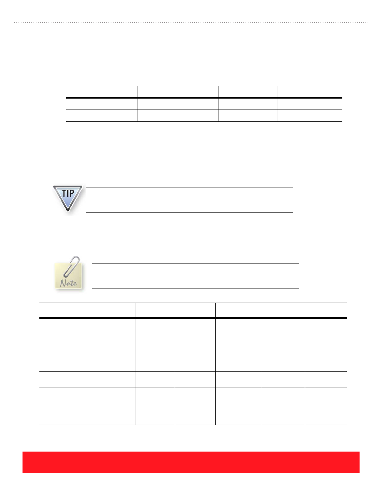
Features After Upgrade 8400N & DP
(Upgrade)
Disk Collation DX upgrade
Walk-Up Features DX upgrade
Support for Print-Ready Document
Manager Via CentreWare IS
Storage for CentreWare IS
Context-Sensitive Help
Increased Storage for Fonts,
Macros, Systart Jobs, & Job
Accounting Records
User Manuals, Videos, & Drivers 33Not supported
required
required
DX upgrade
required
DX upgrade
required
33Not supported
8400DX
(Standard)
3 Not supported
Proof,
Saved,
Secure
3 Not supported
3 Not supported
8500N & DN
(Unsupported)
or tested
Not supported
or tested
or tested
or tested
or tested
or tested
8550DP & DT
(Upgrade)
33
Proof, Saved,
Secure,
Personal
33
33
33
33
8550DX
(Standard)
Proof, Saved,
Secure,
Personal
PHASER 8550, 8500, & 8400 OVERVIEW SECTION
Version 1.0
page 11
Page 20
Options & Upgrades
The Phaser 8400, 8500, and 8550 options and upgrade kits include extra memory, the 525-Sheet
Feeder, the hard drive (Productivity Kit), and configuration upgrades.
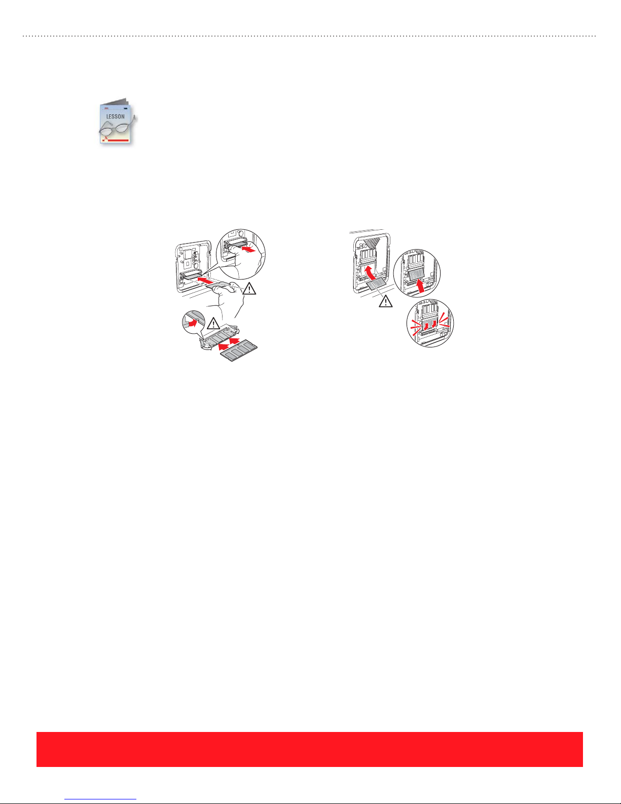
Memory
The Phaser 8400, 8500, and 8550 printers each provide two memory slots. Phaser 8500/8550 memory
modules are physically different than Phaser 8400 modules and are not interchangeable. Memory is located
behind the option cover on both models, but a different installation procedure is required as shown below.
4
Installing Phaser 8400 Memory Installing Phaser 8500/8550 Memory
Phaser 8400 Memory
Phaser 8400 printers include either 128 or 256 MB of memory, so customers will rarely need to install more
RAM. The benefits of adding memory include the following:
■ Increased frame buffer size can improve printing throughput for complex jobs
■ On Phaser 8400N printers with 128 MB of RAM and no hard drive, additional memory increases
the job accounting record capacity from 50 to 500
■ At least 256 MB of memory is required for automatic two-sided printing
The printer supports PC133-compliant, 128 and 256 MB DIMMs. One or two memory DIMMs may be
installed. The supported memory configurations are 128, 256, 384, and 512 MB (any combination of 128 and
256 MB DIMMs).
Phaser 8500 and 8550 Memory
Phaser 8500/8550 printers support more memory than Phaser 8400 printers (1 GB vs. 512 MB) using 128,
256, and 512 MB memory modules. The printers support combinations of 128, 256, and 512 MB modules
(supported configurations are 256, 384, 512, 640, 768 MB, and 1 GB). Adding memory provides more space
for RAM collation, which is supported by Phaser 8550 models with no hard drive. Larger files will
“chunk-collate” when the printer runs short on memory space. Adding memory improves collation and also
increases the frame buffer size to improve printing throughput for complex jobs.
page 12
PHASER 8550, 8500, & 8400 OVERVIEW SECTION
Version 1.0
Page 21
525-Sheet Feeder
The 525-Sheet Feeder adds an extra media tray that is interchangeable with Tray 2. Up to two assemblies can
be installed for a total of three 525-sheet trays plus Tray 1 (MPT). For the supported media types and sizes,
refer to the embedded Paper Tips Page, the Quick Reference Guide, or the User Guide. For Phaser 8500 and
8550 printers, also refer to the Recommended Media List at www.xerox.com/office/8500_8550support
The 525-Sheet Feeder for Phaser 8500/8550 and Phaser 8400 printers is
interchangeable.
Hard Drive (Productivity Kit)
The benefits of adding a hard drive depend on the printer’s model and feature set. Installing the Productivity
Kit into Phaser 8550 DP and DT printers adds all the features of the Phaser 8550DX configuration.
Phaser 8500 printers can be upgraded with full functionality, but the features are not tested or supported.
Upgrading Phaser 8400 N and DP printers adds a limited feature set, while Phaser 8400 B and BD printers do
not recognize the hard drive after installation. Refer to “Hard Drive Features” on page 11 for a summary.
Configuration Upgrades
There are no configuration upgrade kits available for Phaser 8500 or 8550 printers. However, customers can
purchase the components needed to upgrade their Phaser 8550 printer. Use the following table as a guide.
.
Configuration Upgrade Parts Required Benefits
Phaser 8550DP to DT 525-Sheet Feeder Increases paper capacity by 525 sheets
Phaser 8550DP to DX Productivity Kit (hard drive)
256 MB memory module
Two 525-Sheet Feeders
Phaser 8550DT to DX Productivity Kit (hard drive)
256 MB memory module
525-Sheet Feeder
NEVER attempt to convert Phaser 8400 printers to Phaser 8500 models or to
convert Phaser 8500 models to Phaser 8550 printers.
Increases paper capacity by 1050 sheets
Adds Proof, Saved, Secure, and Personal Print
features, disk collation, expanded storage for fonts,
and other hard disk features
Increases paper capacity by 525 sheets
Adds Proof, Saved, Secure, and Personal Print
features, disk collation, expanded storage for fonts,
and other hard disk features
Five upgrade kits are available to change the feature set and add functionality to Phaser 8400 printers. Each
kit provides a Configuration Card, which controls the printer’s feature set regardless of the installed options
or total memory. Users can determine their printer’s feature set by selecting the Printer Identification menu
on the Control Panel.
PHASER 8550, 8500, & 8400 OVERVIEW SECTION
Version 1.0
page 13
Page 22
Use the following table to determine the components required to upgrade Phaser 8400 printers. Each kit that
adds automatic two-sided printing includes a 128 MB memory DIMM, because the printer requires 256 MB
of total memory to process duplex pages.
Phaser 8400 Upgrade Upgrade Components New Features
Features
B to N
B to BD
N to DP
N to DX
DP to DX
A 525-Sheet Feeder is not included in the Phaser 8400DX upgrade kits.
Configuration Card
Instructions to access
Ethernet port
Configuration Card
128 MB memory DIMM
Configuration Card
128 MB memory DIMM
Configuration Card
128 MB memory DIMM
Hard drive
Configuration Card
Hard drive
Network connectivity
CentreWare IS, PrintingScout,
troubleshooting via PhaserSMART
Automatic two-sided printing
Job pipelining
Automatic two-sided printing
Job pipelining
Automatic two-sided printing
Job pipelining
All hard drive features including Collation and
Proof/Saved/Secure Printing
All hard drive features including Collation and
Proof/Saved/Secure Printing
Phaser 8400, 8500, and 8550 printers include a variety of features that are common to Xerox
Phaser printers. Refer to the User Guide or Reference Guide for a list of features that may be
selected using the printer driver, Control Panel, and CentreWare IS. This section describes the
Print-Quality Modes, factors that can reduce print speed, printing grayscale images, the “run
black” mode, and the Walk-Up Features.
Speed & Quality
The printer’s Print-Quality Mode establishes the maximum print speed and resolution.This topic describes
the two PCL Print-Quality Modes and four PostScript Print-Quality Modes for Phaser 8400, 8500, and 8550
printers. Recommended uses for each of the PostScript Print-Quality Modes are provided below:
■ Fast Color - Fastest full-color mode, useful for many images, rapidly producing review
documents, previewing work, and rush jobs.
■ Standard - General-purpose mode for full-color printing. Produces crisp, bright prints at high
speed. Recommended for vibrant, saturated color prints.
■ Enhanced - Best mode for business presentations. Produces superior text resolution and smooth
color transitions. Enhanced is the factory default.
page 14
PHASER 8550, 8500, & 8400 OVERVIEW SECTION
Version 1.0
Page 23
■ High Resolution/Photo (2400 FinePoint™) - Highest quality mode for color prints. Provides the
best detail and smoothness for photographic images. Produces highest-quality color prints with the
best text resolution and smoothest light colors.
The High Resolution/Photo mode uses image enhancement technology to
produce photo-quality images.
Phaser 8500 and 8550 Print-Quality Modes
The Print-Quality Modes and maximum print speeds are different for the Phaser 8500 and 8550 printers. Use
the chart below to determine the available Print-Quality Modes as well as the maximum print speeds. The
term “ppm” means pages per minute and “spm” means sides per minute for two-sided pages.
Printer
Phaser 8500N
Phaser 8500DN
Trays 2, 3, & 4
Phaser 8550DP
Phaser 8550DT
Phaser 8550DX
Trays 2, 3, & 4
All Models
Tray 1 Only
Fast Color
225 x 400 dpi
24 ppm
30 ppm
20 spm
15 ppm 12 ppm 8 ppm 5 ppm 10 ppm 7 ppm
Standard
300 x 450 dpi
N/A 12 ppm N/A 11 ppm N/A
24 ppm
18 spm
Phaser 8400 Print-Quality Modes
The Print-Quality Modes and maximum print speeds are the same for all Phaser 8400 printers, as shown in
the following chart.
Printer
All Phaser 8400
Configurations
Trays 2, 3, & 4
Fast Color
300 x 300 dpi
24 ppm
17 spm
Standard
300 x 450 dpi
18 ppm
14 spm
Enhanced
(1200 FinePoint™)
16 ppm
13 spm
Enhanced
563 x 400 dpi
12 ppm
10 spm
HighRes/Photo
(2400 FinePoint™)
10 ppm
8 spm
HighRes/Photo
(2400 FinePoint™)
7 ppm
6 spm
PCL 600x300 PCL 600x600
11 ppm 8 ppm
PCL 600x300 PCL 600x600
13 ppm 6 ppm
All Phaser 8400
Configurations
Tray 1 Only
PHASER 8550, 8500, & 8400 OVERVIEW SECTION
Version 1.0
12 ppm
10 spm
9 ppm
7 spm
6 ppm
5 spm
3.5 ppm
3 spm
6.5 ppm 3 ppm
page 15
Page 24

Factors That Reduce Print Speed
Many factors, in addition to the Print-Quality Mode and duplex printing, can reduce the print speed:
■ Transparency Jobs - These jobs require a slower transfix speed than printing on paper. A two-pass
printing process is used in the Enhanced and High Resolution/Photo Print-Quality Modes.
■ Legal-Size Jobs - These jobs require a slower transfix speed than printing on A/A4-size sheets.
■ Tray 1 Jobs - Printing from the Tray 1 (MPT) reduces maximum print speeds by approximately
50% when compared to the 525-Sheet Trays.
■ PCL Jobs - The maximum print speed using a PCL driver is slower than printing the same file
using a PostScript driver. To achieve maximum print speeds, use the PostScript printer driver.
■ Jet Substitution Mode - The printer’s Jet Substitution Mode may require more imaging time and
reduce the print speed. Jet Substitution Mode for Phaser 8500 and 8550 printers has less impact on
printer performance and may be used as an end solution for print-quality problems, while the
Phaser 8400 Jet Substitution Mode provides a temporary solution only. Refer to “Jet Substitution”
on page 59 for more information.
Print Grayscale Images
The printer mixes cyan, magenta, and yellow
(CMY) ink with black to improve gradient
fills and gray tones. The combinations of
black and CMY inks vary depending on the
Print-Quality Mode and color correction
setting. Customers can print using only black
ink by selecting the “Black & White” mode,
as shown to the right. Using this mode
avoids color tinting that can occur when
printing composite blacks using CMY and K
inks.
Select “Black
& White” to
Print Using
Black Ink Only
Run Black Mode
When Phaser 8500 and 8550 printers run out of cyan, magenta, or yellow ink, the user is given the choice to
continue printing using black ink only. This capability is known as “run black” mode. Although many other
Phaser printers have the “run black” capability, Phaser 8500 and 8550 printers are the first solid ink models to
include this feature. For example, when Phaser 8400 printers run out of any color of ink, the Control Panel
status LED turns red and the “out of ink” message is displayed. The user must replenish the missing color in
order to continue printing.
If a Phaser 8500 or 8550 printer runs out of CMY ink, users can select the Black & White Color Correction to
continue printing using “run black” mode. Black & White is available on the TekColor driver properties
window shown above. If the printer runs out of cyan, magenta, or yellow ink and no more ink sticks are
available, cancel the current job. To print in “run black” mode, select Black & White and resend the job.
page 16
PHASER 8550, 8500, & 8400 OVERVIEW SECTION
Version 1.0
Page 25
Speed & Quality Review Exercise
Use the information provided in this section to recommend solutions for the following customer
examples.
The answers for this exercise are located in the Appendix on page page 89.
1. If a customer indicates that his printer is too slow when printing transparencies, what solution
could you recommend? __________________________________________________________
2. A customer is printing letterhead from Tray 1 using the High Resolution/Photo Print-Quality
Mode. What are two suggestions you can give her to increase the print speed? ______________
_____________________________________________________________________________
3. What advice would you give a customer who has ordered more cyan ink because her printer ran
out of cyan, but she has an immediate need to print a draft copy of her document? ___________
_____________________________________________________________________________
Walk-Up Features
A range of features involving the printer drivers, Control Panel menu, and hard drive are bundled together as
the Walk-Up features. This topic provides an overview of the Walk-Up Printing technology followed by
descriptions of the Walk-Up installation process, Walk-Up features, and the special Walk-Up printer driver.
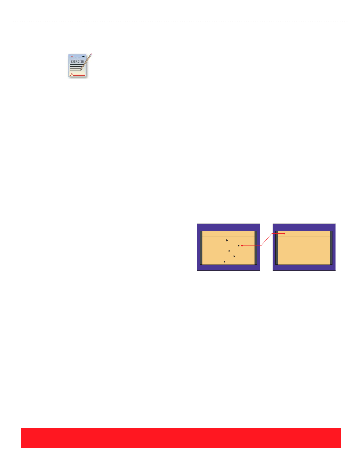
Walk-Up Printing/Technology
The Phaser 8400, 8500, and 8550 Control Panel
contains the Walk-Up Features menu shown to the
right. This menu provides access to the Walk-Up
Printing menu and the Select for Installation
feature.
■ Walk-Up Printing Menu - Select this
menu to search the printer’s hard drive
for any Proof, Saved, Secure, or Personal
print jobs and to select them for printing.
Only Phaser 8550 printers support
Personal print jobs.
Ph ase r 8400 Ph ase r 8400
Ready to Print
Information
Walk-Up Features
Printer Setup
Troubleshooting
Shut Down
Walk-Up Printing
Select for Installation
Exit
Walk-Up Features
■ Select for Installation - When installing the printer driver, use this feature to identify the printer
for installation over the network (see “Walk-Up Driver Installation” for details).
Walk-Up Driver Installation
The printer’s Walk-Up Installation capability simplifies the printer driver installation process. When
installing a Windows driver, if the installer detects more than one Phaser 8400, 8500, or 8550 printer
connected to an Ethernet network, the option “Use Walk-Up Technology” will appear.
PHASER 8550, 8500, & 8400 OVERVIEW SECTION
Version 1.0
page 17
Page 26
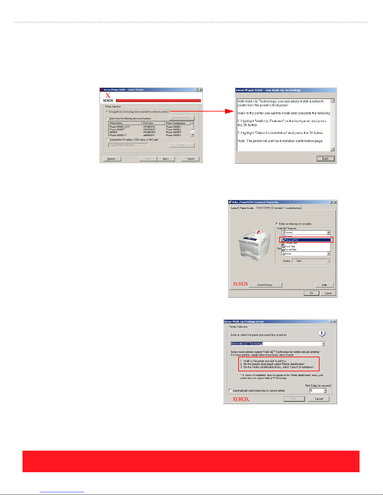
As shown to the left below, the installer provides an option to “Use Walk-Up Technology” for the driver
installation. The installer displays instructions, as shown to the right, which prompt the user to navigate the
Control Panel menus and choose “Select for Installation.” After the user presses the Control Panel’s OK
button, the printer sends its information to the computer. After the printer’s information arrives, the installer
automatically loads the driver for that printer with no more user interaction.
Selecting Walk-Up Driver Installation “Select for Installation” Instructions
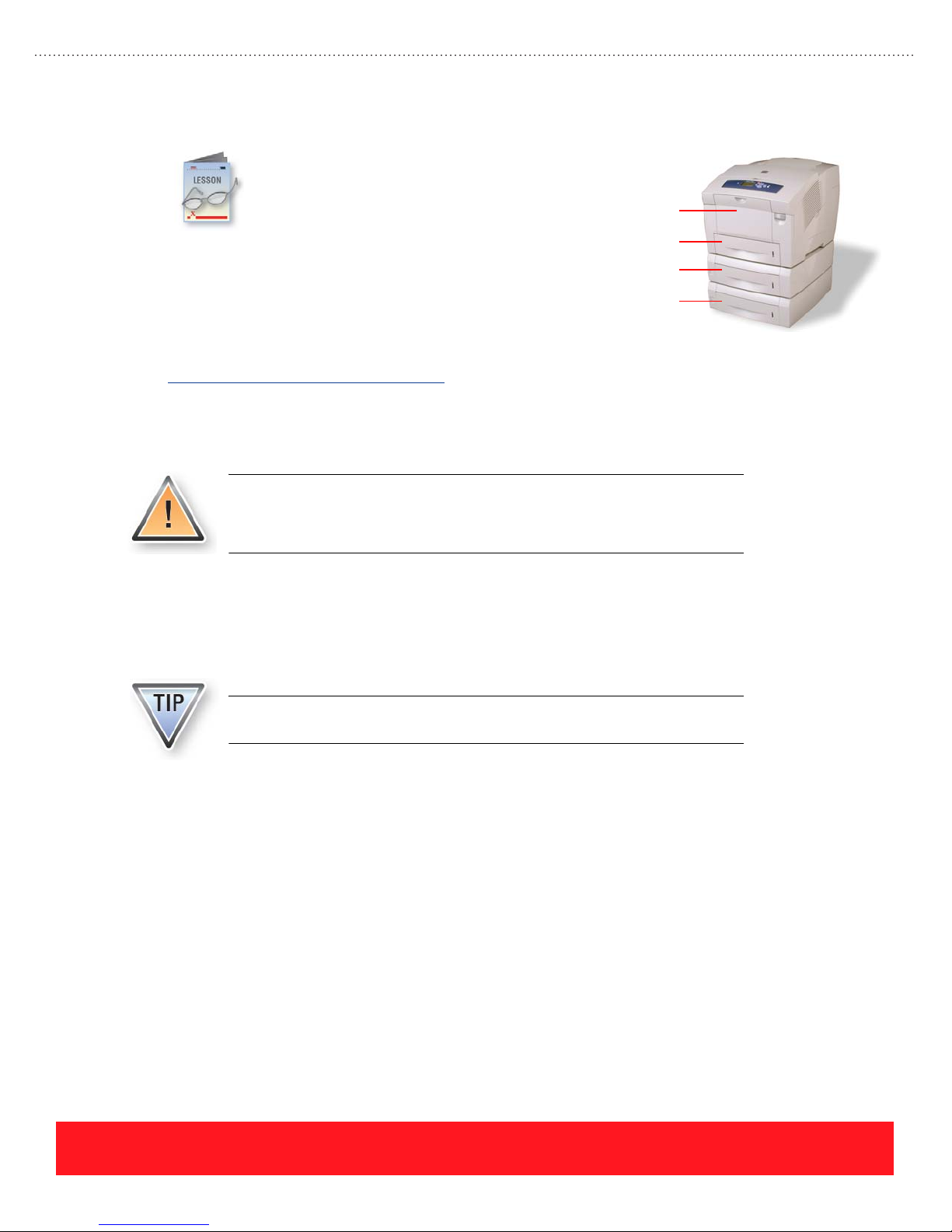
Walk-Up Features
When Phaser 8400DX printers and all
Phaser 8550 printers are equipped with a hard
drive or Productivity Kit, users can designate a
job as Proof, Saved, or Secure. These choices are
available in the printer driver’s Walk-Up Features
pull-down menu, shown to the right.
Phaser 8550 printers offer an additional feature
called Personal Print. It provides a virtual mailbox
feature, allowing users to send a job and then print
at their convenience using the printer’s Control
Panel or CentreWare IS.
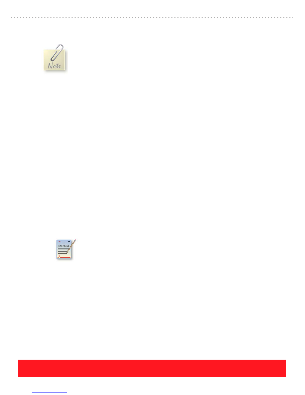
Walk-Up Driver
The Walk-Up Driver shown to the right is designed for
people who travel frequently, and may have a variety of
different Xerox PostScript office printers available
depending on the user’s current location. Instead of
reinstalling and configuring printer drivers every time they
need to print, the user installs one driver that works with
many Xerox printers. When the user connects to a network
with a Phaser 8400, 8500, or 8550 printer installed, they
can select the Walk-Up Driver, choose “Use Walk-Up
Technology,” and print a job. The computer holds the job
until the user chooses Walk-Up Printing on the printer’s
Control Panel. After the computer receives a signal from
that printer, it sends the job for printing.
page 18
PHASER 8550, 8500, & 8400 OVERVIEW SECTION
Version 1.0
Page 27
Media Support
based on 20 lb. bond paper (75 g/m
525-Sheet Feeders may be installed to increase the
total paper capacity to 1675 sheets (525 sheets x 3
trays + 100 sheets for Tray 1).
The Recommended Media List for Phaser 8500 and 8550 printers is located online at
www.xerox.com/office/8500_8550support
media available from Xerox. Additional sources for media support include the embedded Paper Tips Page,
the Quick Reference Guide, and the User Guide. These documents provide general information about the
supported media sizes, weights, and types, but they do not provide ordering information.
Phaser 8400 printers do not support Phaser 860 and 8200 Glossy Paper. Some
types of glossy paper will stick to the Transfix Roller, possibly resulting in a
service call. A new Transfix Roller is used in Phaser 8500 and 8550 printers to
correct this problem.
Each Phaser 8400, 8500, and 8550
printer includes a 100-sheet
Multi-Purpose Tray called Tray 1 and a
525-sheet standard media tray called
Tray 2. The capacities of each tray are
2
). Up to two
. This website provides up-to-date information about the current
Tray 1 (MPT)
Tray 2
Tray 3 (Optional)
Tray 4 (Optional)
Tray 1 (MPT)
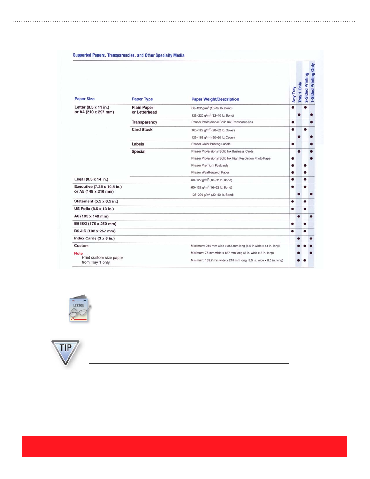
The Tray 1 (MPT) is optimized for printing on paper that is at least 90 g/m2 (24 lb. bond), although lighter
weights are supported. It handles the widest variety of media types and sizes, including the following:
■ Standard paper sizes:
■ Plain paper up to 220 g/m
■ Card stock up to 163 g/m
■ Phaser Professional Solid Ink Business Cards
■ 10 sizes of envelopes
■ Custom size paper:
Use only the Tray 1 (MPT) for printing on custom sizes, A6 paper, 3 x 5 inch
Index Cards, and Phaser Professional Solid Ink Business Cards.
■ Largest size – Legal (8.5 x 14 in)
■ Smallest sizes – A6 and 3 x 5 inch Index Cards
2
2
■ Minimum dimensions – 75 mm wide x 127 mm long (3 x 5 in)
PHASER 8550, 8500, & 8400 OVERVIEW SECTION
Version 1.0
page 19
Page 28
■ Maximum dimensions – 216 mm wide x 355 mm long (8.5 x 14 in.)
Phaser 8500/8550 printers allow 5 mm margins on all sides of custom size
pages. When printing custom sizes on Phaser 8400 printers, the minimum
page margin is 12.5 mm.
525-Sheet Tray (Trays 2, 3, & 4)
The 525-Sheet Trays have adjustable guides with clearly marked positions that allow the tray to support the
following media sizes and types:
■ Supported sizes – Letter, A4, Legal, Executive, A5, Statement, US Folio, B5 ISO, B5 JIS
■ Supported types:
■ Plain paper from 16 – 32 lb. bond (60 – 120 g/m
2
)
■ Light card stock from 100 – 120 g/m
■ Phaser Professional Solid Ink Transparencies
■ Phaser Professional Solid Ink High Resolution Photo Paper
■ Phaser Premium Postcards
■ Phaser Weatherproof Paper
■ Phaser Trifold Brochures
■ #10 Commercial, DL, and C5 envelopes
Media Support Review Exercise
Use the chart from the Phaser 8400 Paper Tips Page to determine which of the following
media must be printed using Tray 1.
The answers for this exercise are located in the Appendix on page page 89.
1. 8.5 x 11 inch sheets of 32 lb. bond: ________________________________________________
2. A6-size sheets of 20 lb. plain paper: _______________________________________________
2
3. Phaser Color Printing Labels: _____________________________________________________
4. 100 mm x 200 mm custom-size sheets of 32 lb. plain paper: ____________________________
PHASER 8550, 8500, & 8400 OVERVIEW SECTION
Version 1.0
page 20
Page 29
Documentation & Software
The printers ship with a complete set of user documentation and software. Phaser 8400 printers
have a separate User Documentation CD-ROM and Printer Installer & Utilities CD-ROM. The
Phaser 8500 and 8550 printer drivers and user documentation are delivered on a single Software
and Documentation CD-ROM. This section provides a quick overview of the printed user
documentation, electronic manuals, videos, embedded pages, and drivers & utilities.
Use the Resources section on the training CD-ROM to view or print copies of
the user documentation.
PHASER 8550, 8500, & 8400 OVERVIEW SECTION
Version 1.0
page 21
Page 30
User Manuals & Guides
The following user documentation is available for the printers:
Document Format Content Description
Videos
Setup Guide Printed poster
(standard accessory)
Quick Reference
Guide
User Guide
(Phaser 8500/8550)
Reference Guide
(Phaser 8400)
Advanced Features
Guide
(Phaser 8500/8550
only)
Printed manual
(standard accessory)
Soft copy This manual provides detailed descriptions of the printer
Soft copy
(Internet access
required for viewing)
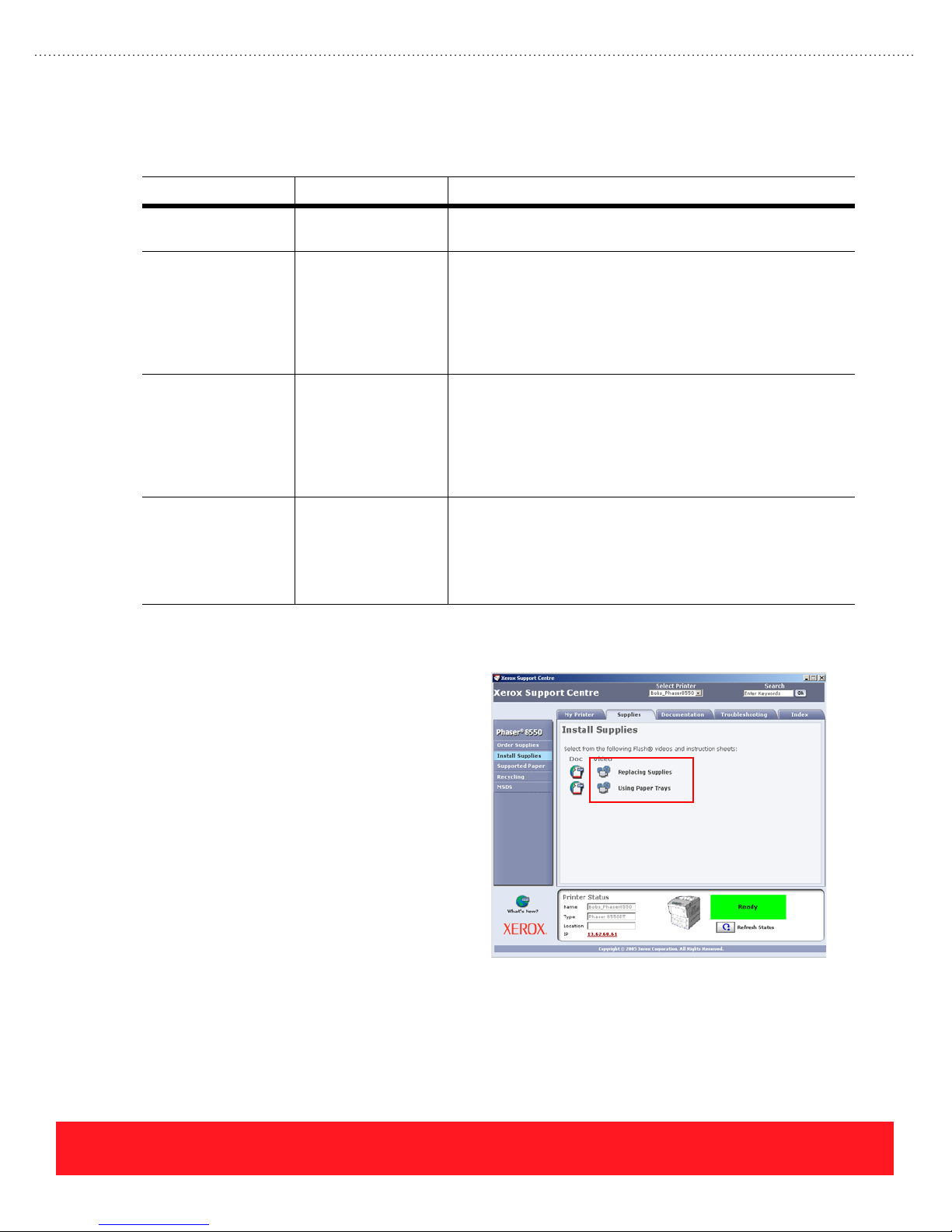
Videos are available to demonstrate the
procedures for installation, printing, and user
maintenance. The videos can be accessed
using CentreWare IS, the Phaser 8400 User
Documentation CD-ROM, or the Phaser
8500/8550 printers’ Xerox Support Centre
shown to the right. Many videos are also
available from the Resources section of the
training CD-ROM.
This printed poster provides visual instructions for installation.
This printed guide should be stored in the printer’s
documentation pocket. It provides the most commonly-needed
user information including tours of the printer and Control
Panel, supported papers, and instructions for basic printing.
Also provided are troubleshooting instructions for print quality
and paper jams. The Phaser 8500/8550 Quick Reference
Guide includes an overview of the Xerox Support Centre.
features, instructions for basic network installation, and
procedures for printing. Additional topics include print quality,
printer maintenance, and troubleshooting. When loading the
Phaser 8500/8550 printer software, a .pdf version of the User
Guide is installed on the user’s computer for access using the
Xerox Support Centre.
An Internet connection is required to access this manual using
the Xerox Support Centre. The guide contains instructions for
using advanced features such as printing in black & white,
booklets, or custom sizes. Instructions are provided for using
Proof, Saved, Secure, or Personal Print, managing fonts,
printing on specialty media, and for networking.
Accessing Videos Using
Xerox Support Centre
page 22
PHASER 8550, 8500, & 8400 OVERVIEW SECTION
Version 1.0
Page 31

Embedded Pages
The Control Panel provides access to embedded pages for setting up, using, and troubleshooting the printer.
Embedded pages can be located in more than one menu. Study the chart to learn about the most
commonly-used pages.
Embedded Page Menu Location Description
Configuration Page Information
Pages Menu
Connection Setup
Page
Help Guide
(Phaser 8400 only)
Moving Guide
(Phaser 8400 only)
Paper Tips Page Information
Troubleshooti ng Print
Quality Page
Usage Profile Information
Information Menu
Connection Setup
Menu
Information
Pages Menu
Information
Pages Menu
Pages Menu
Troubleshooting
Menu
Print Quality
Menu
Troubleshooting
Menu
Pages Menu
Prints a summary of information that identifies the printer, its
installed options, and settings.
Describes how to connect the printer using the parallel, USB,
and Ethernet ports.
Provides hints and tips for solving printing problems by
directing users to sources of information on a variety of topics.
Provides cautions that apply when moving the printer, and
specific instructions for moving within the office and preparing
the printer for shipment.
Summarizes the supported media types and sizes for each
tray and provides tips for loading the trays to achieve the most
reliable operation.
Helps users get the best colors and print quality by providing
information about media, troubleshooting instructions for the
most common print-quality problems, and color settings such
as Print-Quality Modes and TekColor Color Correction
settings.
Provides usage information such as the average percent
coverage, paper sizes used, and number of color versus black
& white prints.
PDF versions of many embedded pages are available from the Resources
section of the training CD-ROM.
Printer Drivers & Utilities
The drivers and utilities are available from the Xerox website, the Phaser 8400 Printer Installer & Utilities
CD-ROM, the Phaser 8500/8550 Software and Documentation CD-ROM, and the printer’s hard drive (when
installed). The website contains the most up-to-date and comprehensive list of printer drivers.
Always use www.office.xerox.com to access the most current software.
PHASER 8550, 8500, & 8400 OVERVIEW SECTION
Version 1.0
page 23
Page 32
Printer Drivers
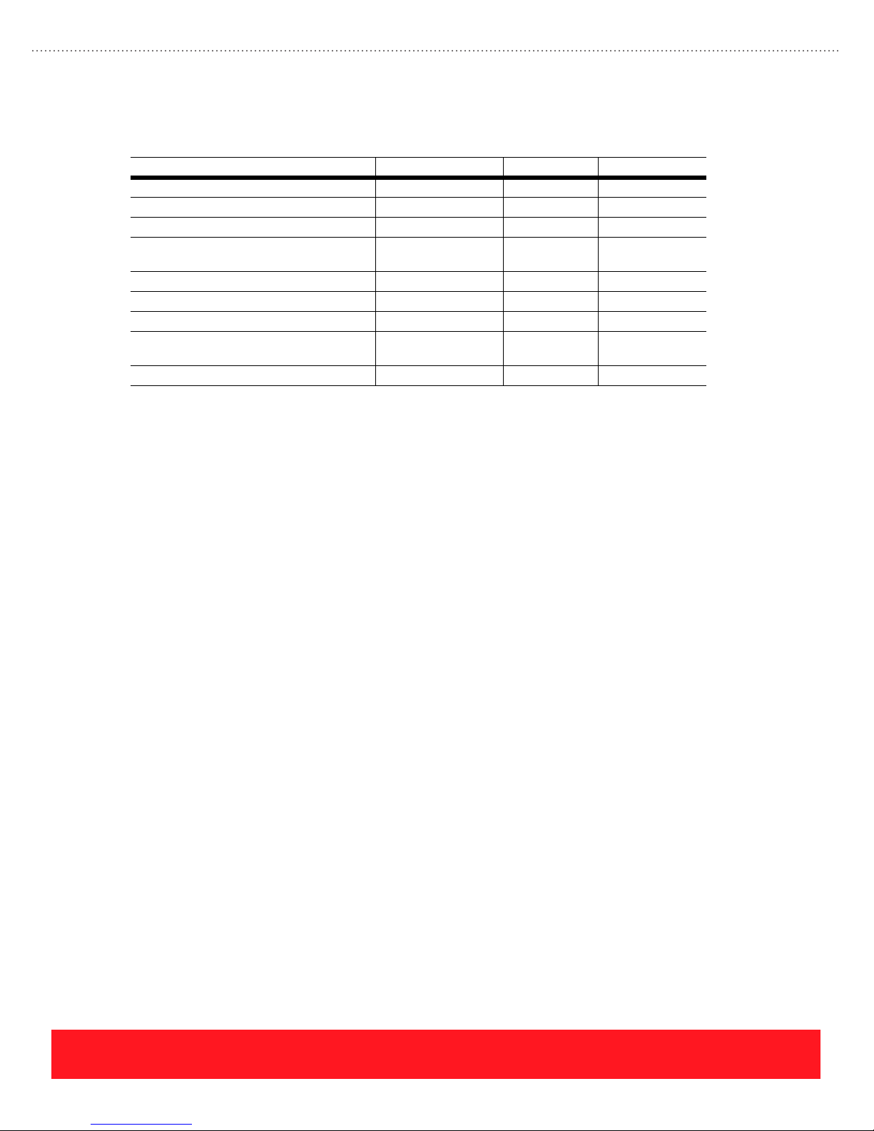
Study the chart to determine where to access the supported printer drivers.
Drivers Software CD-ROM Hard Drive Xerox Website
Windows XP/2003 PS Driver Yes Yes Yes
Windows 2000 PS Driver Yes Yes Yes
Windows 98/Me PS Driver Yes Yes Yes
Windows NT PS Driver
(Phaser 8400 only)
Mac OS 10.x Driver Yes Yes Yes
Mac OS 9.x Driver Yes Yes Yes
Windows 2000/XP PCL Drivers No No Yes
Xerox Walk-Up Printer Driver & Installer
for Windows 2000/XP
UNIX Drivers No No Yes
Ye s Ye s Ye s
No No Yes
The Phaser 8400, 8500, and 8550 printer drivers are similar, but not identical. Three features that are unique
to the Phaser 8500/8550 printer drivers include Personal Print, the 2nd Side Paper Type, and the Color
Adjustment Sliders:
■ Personal Print - Personal Print provides a virtual mailbox feature, allowing users to send jobs and
then print at their convenience using the printer’s Control Panel or CentreWare IS.
■ 2nd Side - This paper type option provides a workaround to avoid smearing when manually
duplexing preprinted solid-ink pages. Phaser 8500/8550 printers achieve faster print speeds than
Phaser 8400 printers by increasing the preheater temperature. This choice compensates for the
increased temperature.
■ Color Adjustment Sliders - This feature allows advanced users to customize the TekColor Color
Corrections. See “Color Adjustment Sliders” on page 25 for details.
Utilities
The printer utilities listed below are available from the Xerox website to support Phaser 8400, 8500, and
8550 printers. The Usage Analysis Tool enables system administrators to collect, organize, and analyze Job
Accounting data from multiple printers. It is often used to roll up usage statistics by individual users or
groups in order to calculate charge-back billing or to plan for optimized printer deployment.
■ Usage Analysis Tool & Installer
■ MaiLinX Client & Installer
■ Font Management Utility
■ CentreWare Web/MC & Installers (Phaser 8400 also supports CentreWare DP)
■ NDPS Gateway & Installer
page 24
PHASER 8550, 8500, & 8400 OVERVIEW SECTION
Version 1.0
Page 33
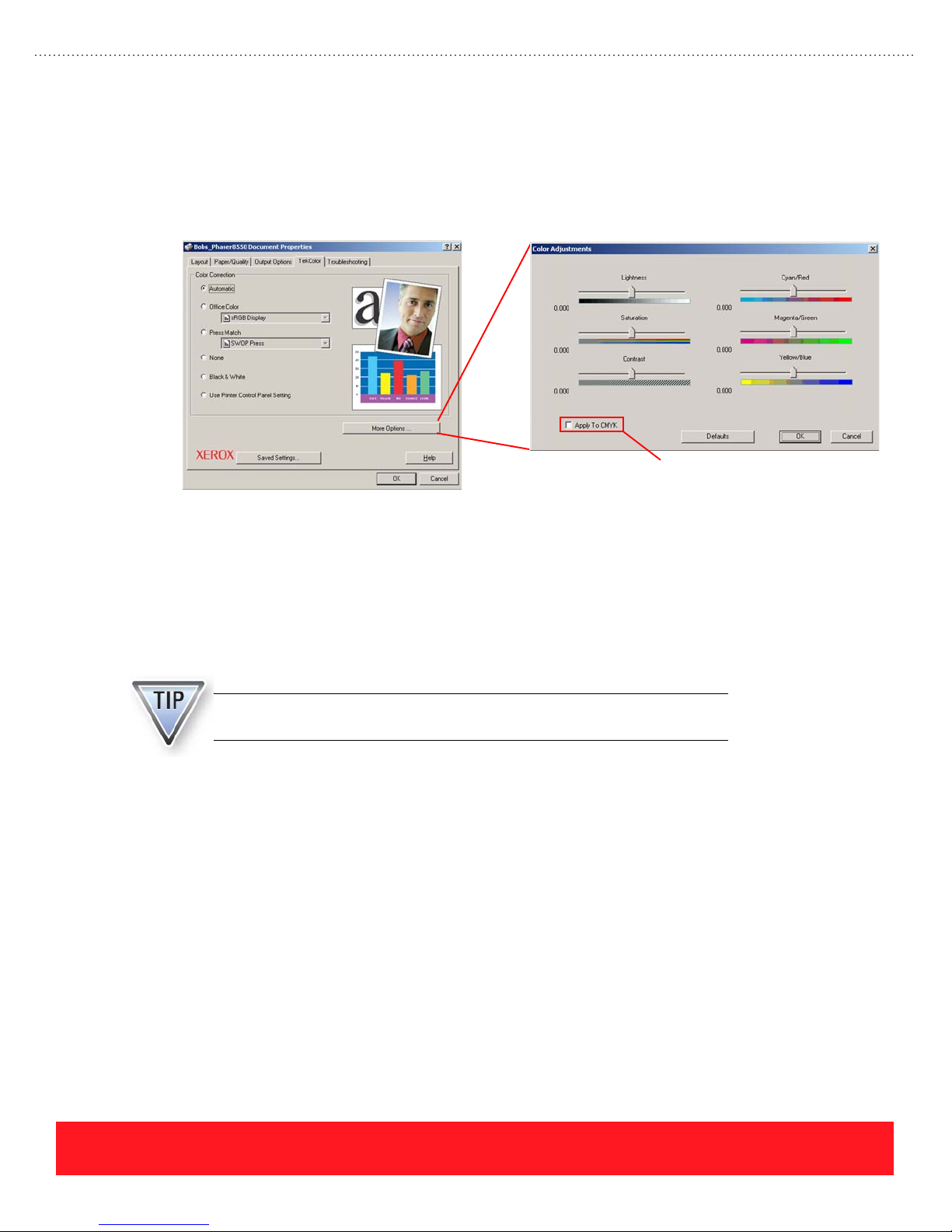
Color Adjustment Sliders
The Phaser 8500 and 8550 TekColor driver properties page contains the standard Color Correction settings in
addition to a “More Options” button. Advanced users can choose this feature to adjust colors for the current
Color Correction setting. If one of the “Press Match” settings are selected, the “Apply to CMYK” checkbox
must also be selected in order to implement the slider settings, as shown in the example below.
Customers who are having color problems should begin the troubleshooting process by defaulting the Color
Adjustments (all sliders set to 0.000). They must also be aware that the adjustments always apply to the
active Color Correction setting. For example, a customer may select the Color Correction “None” and then
adjust the sliders to customize the printed output. If the customer changes the Color Correction to
“Automatic”, the sliders will not default to 0.000. Instead, the Color Adjustments previously selected for
“None” will be applied to the “Automatic” setting. Prints generated in this mode will have different colors
when compared to prints that use the “Automatic” Color Correction and no Color Adjustment.
Select to customize
the “Press Match” settings
When troubleshooting color issues on Phaser 8500 and 8550 printers,
always begin by resetting the Color Adjustment sliders to 0.000 (default).
PHASER 8550, 8500, & 8400 OVERVIEW SECTION
Version 1.0
page 25
Page 34
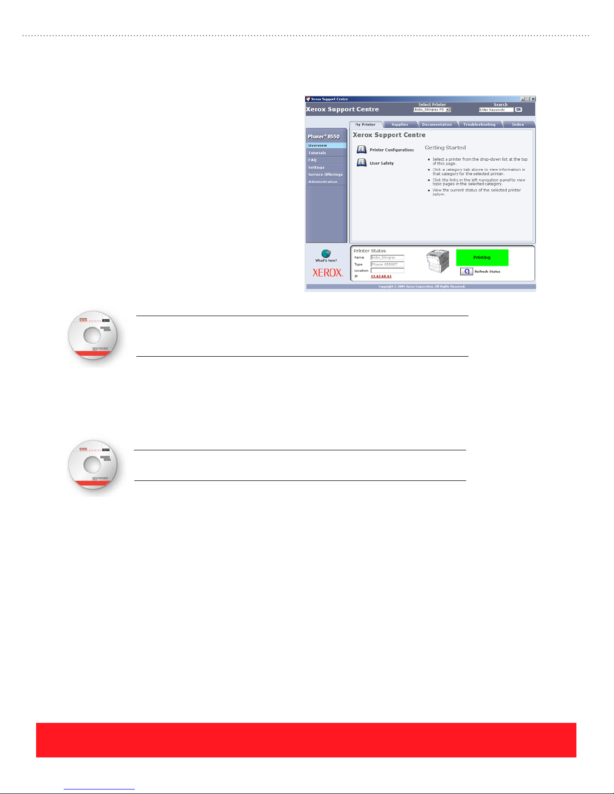
Xerox Support Centre
Loading the Phaser 8500/8550 printer
software installs the Xerox Support Centre in
addition to the printer driver. This utility
provides a single location for accessing user
documentation, setting printer driver
properties, and going online to access features
such as CentreWare IS, support websites, the
knowledge base, and PhaserSMART.
During the software installation, the Installer
creates a shortcut to the Xerox Support Centre
and saves it on the computer desktop. After
the installation completes, the Xerox Support
Centre automatically opens to provide
immediate access to its features.
An optional multimedia lesson called “Xerox Support Centre” is available on
the training CD-ROM. To access the lesson, select the Resources section of
the training CD-ROM and choose “User Videos”.
Your Next Step
You have completed the Overview section of the Self-Study Guide.
Return to the training CD-ROM and complete the Overview Self-Check. Then,
select the Setup section on the CD-ROM to continue.
page 26
PHASER 8550, 8500, & 8400 OVERVIEW SECTION
Version 1.0
Page 35
Phaser 8550, 8500, & 8400 Service Self-Study Guide
SETUP SECTION
Prerequisites
❑ Setup section of the
Phaser 8550, 8500, &
8400 Product Training
CD-ROM
Time To Complete
❑ Reading: 35 min.
❑ Video run time: 20 min.
❑ Exercises: 20 min.
❑ Optional labs: 60 min.
Equipment Checklist
❑ Adobe
❑ Phaser 8500 & 8550
❑ Phaser 8400 Installer &
❑ Phaser 8550, 8500, or
®
Software and
Documentation
CD-ROM (optional)
Utilities CD-ROM
(optional)
8400 printer (optional)
Reader
®
Reference Manuals
Electronic copies of the
product manuals, guides,
and instruction sheets are
located on the training
CD-ROM.
Use the training CD-ROM’s
Resources section to access
the manuals and other
documentation.
Setup Objectives
■ Setup the printer (if printer available)
■ Load paper and specialty media correctly into the trays
■ Navigate the Control Panel menus
■ Test the communication ports
■ Print documents (if printer is available)
■ Install upgrades
Complete the Setup multimedia lessons on the training
CD-ROM before you begin this section of the Self-Study Guide.
This section of the Self-Study Guide contains a lab for setting up the printer (if
available). It also presents information on loading paper and specialty media,
changing Control Panel settings, testing the communication ports, printing
documents, and installing hardware upgrades.
Refer to the Setup Guide and Phaser 8400 Reference Guide or Phaser 8500/8550
User Guide to complete the exercises and optional labs in this section. Electronic
versions are available from the training CD-ROM’s Resources section.
Setting up the Printer
If you have a Phaser 8550, 8500, or 8400 printer, follow the Setup Guide
to unpack and install it now. Use the steps below as a guide to setup and
power on the printer.
PHASER 8550, 8500, & 8400 SETUP SECTION
Version 1.0
1. If necessary, unpack the printer.
2. Choose the printer location and install the 525-Sheet Feeder (if
available) and the printer.
3. Connect the communications and power cables.
4. Turn on the power switch so the printer begins to warm up.
5. If necessary, load ink.
When you reach the steps for loading paper, changing Control
Panel settings, and loading drivers, read the corresponding
lessons and then perform those installation steps on your printer.
page 27
Page 36
Setup Review Exercise
The answers for this exercise are located in the Appendix on page 90.
1. According to the Setup Guide, what is the first step of the installation process? ______________
_____________________________________________________________________________
2. How many people are required to lift the printer? _____________________________________
3. Which sides of the printer can be within 10 cm (4 in) of the wall? ________________________
4. The surface on which the printer is placed must be level from side-to-side within how many
inches? ______________________________________________________________________
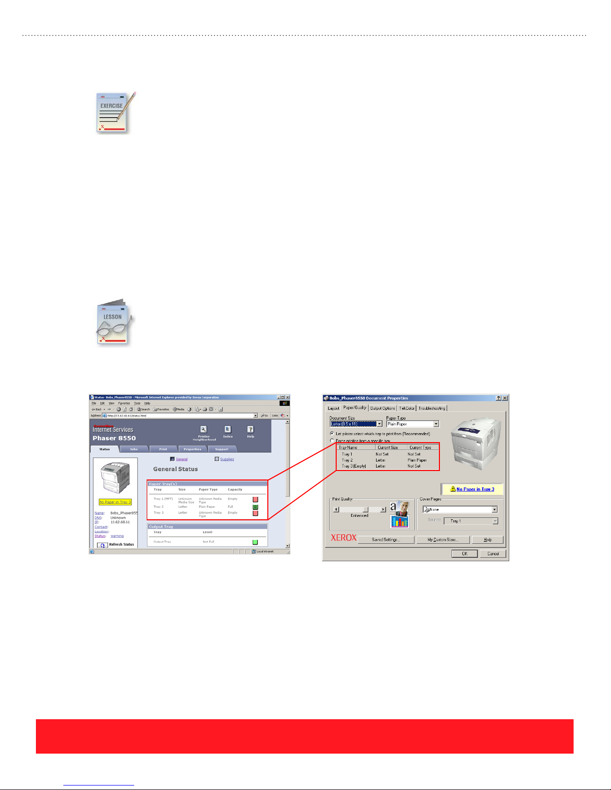
Load Paper
This lesson provides general guidelines for loading paper and specialty media. Tips and hints for
loading the trays are also provided. Use the Phaser 8400 Reference Guide, the Phaser 8500/8550
User Guide, or the embedded Paper Tips Page when completing this lesson. Electronic versions
are available from the training CD-ROM’s Resources section.
Users can refer to the printer driver and, on Phaser 8500 and 8550 printers, the CentreWare IS page to
determine the current media type and size settings as shown in the examples below.
If you do not have a printer, refer to the Setup Guide and complete this exercise. Then, read the
following lessons for loading paper, configuring the Control Panel, testing ports, printing
documents, and installing upgrades.
CentreWare IS Paper Tray Settings Printer Driver Paper Tray Settings
(Phaser 8500 and 8550 only)
page 28
PHASER 8550, 8500, & 8400 SETUP SECTION
Version 1.0
Page 37
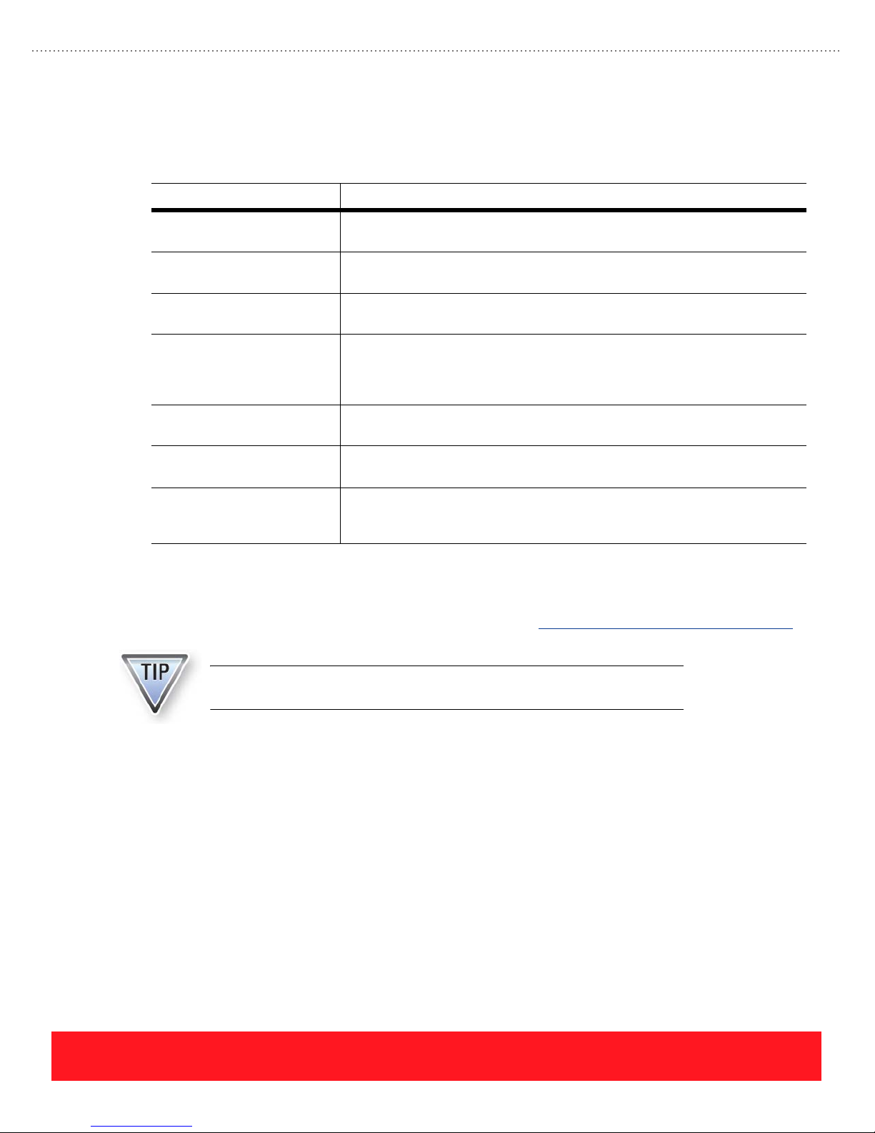
Guidelines
The printers support most common media. However, do not use the media listed in the following table, which
can cause poor image quality, increase the number of jams, or damage the printer.
Media Type Explanation
Transparencies with stripes
on the side
Paper with pre-punched
holes
Media with staples The staples can damage the Paper Feed Rollers, Preheater, Transfix Roller and
Envelopes with metal
clasps, windows, or
adhesives with release
strips
Padded envelopes and
envelopes with side seams
CD labels CD labels printed with Phaser 8400 or Phaser 8500/8550 inks may not
Phaser 860 and 8200
Glossy Paper
(Phaser 8400 only)
The stripes add thickness to one side of the media so the stack is higher on one
side of the tray. If the stack is too high, mispicks, jams, or skewing can occur.
Print-quality problems can occur when the ink image overlaps the holes on the
paper. Spots of ink will stick to the drum and transfer to subsequent pages.
Drum Assembly, causing permanent print-quality problems.
The metal clasps can damage the Preheater, Transfix Roller, and Drum
Assembly, causing permanent print-quality problems. They can also cause
damage to sensor flags. Ink will not stick to the windows, causing print-quality
problems. Adhesives and release strips can gum up or block the paper path.
These envelopes are generally too thick and will cause paper jams. Envelopes
with plastic padding may not withstand the internal printer temperatures.
withstand the temperature of CD-ROM drives.
The coating sticks to the Phaser 8400 Transfix Roller, causing paper jams and
print-quality problems.
Unsupported or damaged media is often the root cause of print-quality and paper-feed problems. To
determine the supported media types and sizes, refer to the embedded Paper Tips Page, the Phaser 8400
Reference Guide, the Phaser 8500/8550 User Guide, or the printed Quick Reference Guide. For Phaser 8500
and 8550 printers, refer also to the Recommended Media List at www.xerox.com/office/8500_8550support
.
Refer to the Quick Reference Guide, Paper Tips Page, Phaser 8400 Reference
Guide, or Phaser 8500/8550 User Guide for printing instructions.
Loading Tray 1 (MPT)
Tray 1 (MPT) is optimized for printing on heavier papers (24 lb. bond or 90 g/m2 or greater). Tray 1 must be
used when printing custom-size pages. To print successfully using Tray 1, observe the following guidelines:
■ Never fill the tray above the fill line (located on the left width guide).
■ Position the media snugly against the pick roller.
■ Adjust the width guide so it gently touches the paper stack.
■ Refer to labels on the tray for the correct orientation for envelopes and letterhead.
■ Always load media short-edge-feed.
PHASER 8550, 8500, & 8400 SETUP SECTION
Version 1.0
page 29
Page 38

Detecting Width
Tray 1’s built-in Paper Present Sensor
detects when paper is placed into the
tray. Users must adjust the guide against
the edges of the paper stack so the guide
Tray 1 Type
& Size
“Not Set”
correctly reports the paper’s width.
When the tray is loaded, the printer’s
Control Panel prompts the user to verify
both paper size and type. If the user
ignores the prompt, the printer driver
indicates the paper size and type are “Not
Set” as shown in the example to the right.
Detecting Length
When a print job specifies Tray 1, the printer uses its Deskew Sensor to measure the length of the first sheet
as it feeds through the paper path. If the sheet is too short for the printed image, the printer prompts for the
correct size and feeds a sheet of paper to clean the drum. If the job prints successfully, the printer updates the
driver with the new Tray 1 settings. If the job fails to print, the user should choose the correct driver settings.
Tray Switching
Phaser 8400, 8500, and 8550 printers default to "Not Set" when the paper type for a media tray is
unconfirmed. However, Phaser 8500/8550 printers have the ability to remember a tray’s previous setting to
minimize user interaction when selecting the media type. For example, users commonly open the trays to
visually determine what paper is loaded. If they check all the trays and then print a job, the trays default to
"Not Set". If one of the trays was previously set for transparency and the print job requests transparency
media, Phaser 8500 and 8550 printers remember the previous setting. In contrast, Phaser 8400 printers
default to the highest priority tray, regardless of the previous settings.
Phaser 8500 and 8550 printers use the following sequence to select the tray for a specified paper type:
1. Select a tray that is configured for the correct paper.
2. If no trays are configured for the specified paper type, check the previously confirmed setting for each
“Not Set” tray. If a previous setting matches the current paper type, print the job using that tray.
3. If the printer fails to locate a tray with the correct media type, prompt the user to load the requested
media. Phaser 8500 and 8550 printers do not specify which tray to load. After the user loads a tray,
the printer sets and confirms that tray for the requested paper type and prints the job.
page 30
PHASER 8550, 8500, & 8400 SETUP SECTION
Version 1.0
Page 39
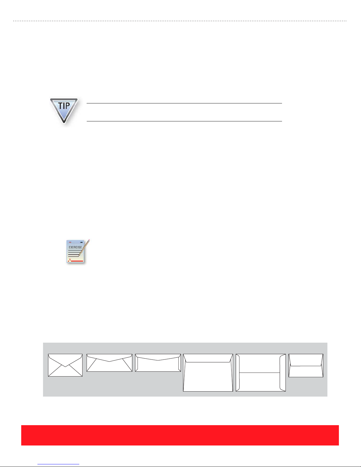
Loading Trays 2, 3, & 4
When paper is loaded into Trays 2, 3, or 4, the user must adjust the width and length guides against the paper
stack. Information from the guides is used to update the printer driver with the media size for that tray. If the
size corresponds to a specific media type, such as DL or C5 envelopes, the driver will also be updated with
the media type. Setting the guides incorrectly causes paper jams because the paper will be narrower or shorter
than expected as it travels through the paper path.
The width and length guides must be set correctly because they detect the
size of paper loaded in the tray.
To print successfully using Trays 2, 3, and 4, observe the following guidelines:
■ Adjust the width and length guides to the correct position before loading the tray with paper. This
allows you to visually see how the guides line up with the paper size indictors, which are located
on the bottom of the tray.
■ Never fill the tray above the fill line (located on the left width guide).
■ Refer to labels on the tray for the correct orientation for envelopes and letterhead.
■ Always load media short-edge-feed.
■ Print custom sizes only from Tray 1 (MPT).
Loading Paper Review Exercise
Use the Phaser 8400 Reference Guide or Phaser 8500/8550 User Guide to answer the
following questions. If a printer is available, you may refer to the labels on the media trays.
The answers for this exercise are located in the Appendix on page 90.
1. To print envelopes with side flaps from Tray 1, the correct position for the flap is:
(Face up or Face down) and (To the left or To the right).
2. To print letterhead on one side from Tray 2, the correct position of the logo is:
(Face up or Face down) and toward the (Front of tray or Back of tray).
3. Select each envelope style that is supported for printing.
(hint: Read the “Printing Envelopes” topic in the Phaser 8500/8550 User Manual or Phaser 8400
Reference Guide.)
AB C D E F
PHASER 8550, 8500, & 8400 SETUP SECTION
Version 1.0
page 31
Page 40
Configure Control Panel
This lesson includes a general overview of the Control Panel menus. It also describes the hidden
Control Panel shortcuts and the defaults that are most often selected during the setup procedure.
Refer to the Menu Map when completing this section. An electronic version is available from the
training CD-ROM’s Resources section.
Menus
The Control Panel includes the main menus listed below. On Phaser 8500 and 8550 printers, the Paper Tray
Setup menu is located at the top level of the menu system, while on Phaser 8400 printers this menu is a
submenu of Printer Setup. The built-in Menu Map provides a graphical representation of the menu system. If
a printer is available, use the following procedure to print the Menu Map for use later in this section:
1. Scroll to highlight Information and press OK.
2. Scroll to Menu Map and press OK to print the two-page Menu Map.
Menu Settings and Information
Walk-Up Features Menu The Walk-Up Features Menu allows users to retrieve Proof, Saved, Secure, and
Information Menu The Information Menu provides access to the Menu Map, printer identification,
Personal Print jobs, or jobs from the Walk-Up driver. When Walk-Up Printing is
selected, the printer searches the network for jobs that use Walk-Up Technology.
information and help pages, sample pages, and supplies information.
Shortcuts
Paper Tray Setup Menu
(Phaser 8500/8550 only)
Printer Setup Menu The Printer Setup Menu allows access to settings for connection setup, paper
Troubleshooting Menu The Troubleshooting Menu contains tips for solving paper jams and print-quality
Shutdown Menu The Shutdown Menu provides options to put the printer in Standby Mode, restart
The Paper Tray Setup Menu allows access to settings for each paper tray and the
paper handling setup options.
handling, PostScript, PCL, Control Panel setup, and printer controls.
problems. The network logs and service tools are also located here.
the printer, or prepare it for power-down.
Several hidden Control Panel shortcuts are available to quickly access information you may need for product
support. The following shortcuts are available:
Function Shortcut Sequence
Access Service Tools menu
(Jam History & Print Engine History)
Set Control Panel language Press and hold the Cancel button, then press the Information button.
Bypass protected menus Press and hold the Cancel button, then press the Back button.
Add Jet Substitution Mode to the
Print Quality Problems menu
(Phaser 8400 only)
Press and hold the Up Arrow button, then press the OK button. You
can also press and hold the Cancel button, then press the OK button.
From the Print Quality Problems menu, press and hold the Up Arrow
button, then press the Back button.
page 32
PHASER 8550, 8500, & 8400 SETUP SECTION
Version 1.0
Page 41
Control Panel Defaults
When setting up a Phaser 8400, 8500, or 8550 printer for the first time, users may need to select the following
Control Panel defaults. Because the menus are different for Phaser 8400 printers when compared to
Phaser 8500 and 8550 menus, the menu path for choosing each default can vary by printer model. Refer to
the Menu Map or the printer’s user documentation for instructions.
Default Setting Benefit
Define paper type for
each tray
Disable Startup Page Turn off the Startup Page to reduce ink usage and reduce the time required to
Select cleaning page
source
Network settings Select the network settings for the network to which the printer is connected.
Control Panel Lab
Test Ports
To avoid print-quality problems when printing on transparencies, configure the
Tray Setup to match the media loaded in each tray.
power on the printer.
Select the cleaning page source if the printer has more than one 525-Sheet
Tray. Tray 2 is the default. Select a tray that will be loaded with plain, letter-size
paper to avoid using expensive media for cleaning.
If a printer is available, use the Menu Map as a guide to set the following Control Panel defaults:
1. Tray 1 paper type and size
2. Tray 2 paper type
3. Startup Page (set to “OFF”)
4. Network settings for your network (if applicable)
5. Cleaning page source (if a 525-Sheet Feeder is installed)
The Test Ports topic of the multimedia training explains how to test the printer’s Ethernet and
USB ports from a Windows 2000 PC. This lesson provides additional procedures for testing the
communication ports. Refer to the Phaser 8400 Reference Guide or Phaser 8500/8550 User
Guide when completing this section. Electronic versions are available from the training
CD-ROM’s Resources section.
PHASER 8550, 8500, & 8400 SETUP SECTION
Version 1.0
page 33
Page 42

Network Diagnostics
Start and runtime logs for diagnosing network problems are available using the menu path
Troubleshooting...Network Problems...Network Log Pages. Network log pages for TCP/IP and
AppleTalk are provided.
A Network Diagnostics tool is provided on Phaser 8500
and 8550 printers. To access Network Diagnostics:
■ Scroll to Troubleshooting and press OK.
■ Scroll to Network Problems and press OK.
■ Scroll to Network Diagnostics and press OK.
The Network Diagnostics process takes about 60 seconds to test the network connection and report errors. It
checks for common causes of communication problems such as collisions, Ethernet speed
mis-configurations, missing hubs (when a crossover cable is not in use), and inappropriate IP settings for the
detected network type or server. In addition to Network Diagnostics, the standard Network Log Pages are
available for troubleshooting.
If a printer is available, disconnect the Ethernet cable and run Network
Diagnostics to see how the printer reports the error. Then, connect the cable
and run diagnostics again to see how it reports a successful test.
Test Windows Ethernet Port (Alternate Procedure)
The printers’ Ethernet port can be tested by using a crossover cable and the “PING” command. The Te st
Ports topic on the training CD-ROM explains how to enable communication by setting a static IP address in
the printer to match the PC’s IP address range. If the PC’s IP address falls within the range 169.254.xxx.xxx,
an alternate procedure is required to test the printer (see below). PCs that have not been configured for a
specific network default to a “LOCAL LINK” value that begins with “169.254”.
Phaser 8550
Network Diagnostics
Network Diagnostics
Network Log Pages
Exit
6350DT
?
To comply with industry standards, Phaser 8400, 8500, and 8550 printers
cannot be manually configured for IP addresses in the LOCAL LINK range.
Use the following procedure to test the printer when the PC’s IP address begins with “169.254”:
Always print the Configuration Page to obtain a record of the printer settings
before changing the IP address. After testing the printer, be sure to restore
the printer’s original network settings.
1. Connect a crossover cable between the PC and printer.
2. Verify the printer is “Ready To Print”.
page 34
PHASER 8550, 8500, & 8400 SETUP SECTION
Version 1.0
Page 43
3. Use the printer’s Control Panel to enable AutoIP:
■ Select the Printer Setup menu.
■ Select the Connection Setup menu.
■ Select the Network Setup menu.
■ Select the TCP/IP Setup menu.
■ Set AutoIP to On.
■ Exit the menu so the printer is “Ready To Print”.
AutoIP mode causes the printer to select an IP address based on other
network devices. In this example only the PC is on the same network.
4. Reset the printer to cause AutoIP to assign a new IP address (cycle power or select Restart
Printer from the Shutdown menu).
5. After the printer’s IP address is set, print the Startup Page or use the Control Panel to determine the
IP address.
6. Using the printer’s IP address, send the “PING” command to test communication.
7. If the test fails, install a different cable and retest.
Test Parallel Port
To test the parallel port on Phaser 8400 printers, install the printer driver and print a test page. This procedure
demonstrates how to test the port by installing the PostScript driver from the printer’s software CD-ROM
onto a Windows 2000 workstation.
1. Connect a cable between the parallel ports on the printer and the PC.
2. Verify the printer is “Ready To Print”.
3. Insert the CD-ROM into the computer’s drive. If the CD fails to auto-launch, explore the
CD-ROM and double-click the Install.exe file to launch the installer.
4. Exit the installer window.
If you are unable to print using the driver, the MS-DOS command window can
be used to bypass the computer operating system.
PHASER 8550, 8500, & 8400 SETUP SECTION
Version 1.0
page 35
Page 44

5. Launch the Add Printer Wizard. Keep the
“automatically detect” box checked as
shown to the right.
6. If prompted, specify the drive where the
driver files are located (CD-ROM).
7. Click “Print Test Page” at the end of the
installation to test the connection.
8. If the test page fails to print, use the
MS-DOS Command Prompt to bypass the
computer’s operating system:
■ Click the computer’s START button and
select RUN.
■ Type “command” and click
OK to launch the MS-DOS
Command Prompt.
■ Type the command “echo
showpage > lpt1:” and press
ENTER (change “lpt1:” to
match the PC’s comm port).
See the example to the right.
■ The printer generates a blank
page if the parallel port is
working.
Test Macintosh USB Port
To test the printer’s USB port from a Macintosh computer, the printer driver must be installed and tested. This
procedure demonstrates how to install the Phaser 8400 PostScript driver (PPD) and generate a test print on a
Macintosh computer running OS 10.2.x.
The procedures for Mac OS 10.2.x and 10.3.x are identical except for the
Print Center and Print Setup Utility. Use the Print Center for 10.2.x
installations and the Print Setup Utility for 10.3.x installations.
1. Connect an A-to-B cable between the USB ports on the printer and Macintosh computer.
2. Verify the printer is “Ready To Print”.
3. Insert the CD-ROM into the computer’s drive.
page 36
PHASER 8550, 8500, & 8400 SETUP SECTION
Version 1.0
Page 45

4. To install the software:
■ Double-click the “Installer” icon to launch the Installer.
■ Click “Continue”.
■ Click “Accept” to accept the license agreement.
■ Click “Install” to begin the installation process. The installer will load the Phaser 8400 PPD into the
correct directory.
■ Click “Quit” after the installation has completed.
5. To launch Print Center:
■ Double-click the hard drive.
■ Select Applications...Utilities...Print Center.
6. To select the PPD:
■ On Print Center, click the ADD icon.
■ Use the pull-down menu to select USB.
■ Select the printer from the Product section (there may only be one).
■ Select “Xerox” from the Printer Model field and then select the correct Xerox printer model (this
selection configures the printer with the correct PPD file).
■ Click the “Add” button.
■ Close the Print Center.
7. To test the connection:
■ Select Applications...TextEdit to launch the TextEdit application.
■ Type a short text message.
■ Select File...Print.
■ Select the Phaser 8400 printer.
■ Click the “Print” button to send the job.
PHASER 8550, 8500, & 8400 SETUP SECTION
Version 1.0
page 37
Page 46

Test Macintosh Ethernet Port
To test the printer’s Ethernet port from a Macintosh computer without connecting to the customer’s network,
use a crossover cable and the Macintosh Network Utility. The printer and computer must be set to the same
range of IP addresses.
The following example demonstrates how to test the Ethernet connection to a
Mac OS 10.1 computer.
1. Verify the printer is “Ready To Print”.
2. To check the computer’s TCP/IP settings, use the Apple menu to select System Preferences:
■ Select “Network”.
■ Select “Show Built-in Ethernet”.
■ Click the TCP/IP tab and record the IP address, subnet mask, and gateway.
3. Use the Control Panel to set the printer’s TCP/IP address:
■ Print the Startup page using the printer’s Information...Information Pages menu path.
■ Use the Startup page to verify TCP/IP is enabled and to check the IP address and Ethernet type. If
the Ethernet type is “not connected,” either the cable or port is broken.
■ Use the printer’s Control Panel to change its IP address to a static IP address that matches the
Macintosh computer except for last field. (For example, if the computer’s IP address is
177.206.21.222, you may use 177.206.21.223).
■ Edit the printer’s gateway and subnet mask to match the computer.
See “Test Windows Ethernet Port (Alternate Procedure)” on page 34 to set the
printer’s IP address if the computer’s IP address is 169.254.xxx.xxx.
4. To test the connection using the Network Utility:
■ Connect a crossover cable between the Ethernet ports on the printer and the computer.
■ Double-click the hard drive icon.
■ Select Applications...Utilities...Network Utility.
■ Click the PING tab.
■ Enter the printer’s IP address.
■ Configure the utility to send four pings. The test will end after four tries.
■ Click the “Ping” button to complete the test.
page 38
PHASER 8550, 8500, & 8400 SETUP SECTION
Version 1.0
Page 47

Printing Lab
■ Install the printer software
■ Print test jobs
■ Use the Xerox Support Centre to access information
The printer’s software CD-ROM includes an
installer for loading the printer driver (the Phaser
8500/8550 Windows installer is shown to the
right). Alternately, CentreWare IS can be used to
download drivers from the printer’s hard drive
or the Xerox website. When installing the Phaser
8500 or 8550 drivers, the system automatically
loads and opens the Xerox Support Centre.
When the installation is complete, a shortcut to
the Xerox Support Centre will be visible on the
computer desktop.
If you have a Phaser 8400, 8500, or 8550 printer, complete this lab to perform the tasks listed
below. If you do not have a printer, please read this section to become familiar with the
following tasks:
Install Software
To complete this step of the lab:
1. Print the Connection Setup Page to access instructions for connecting the printer:
■ Enter the Printer Setup menu.
■ Scroll to Connection Setup and press OK.
■ Press OK again to print the Connection Setup Page.
2. Refer to the Connection Setup Page for instructions to connect your computer to the printer.
3. Install the printer driver onto your computer. If you support multiple operating systems, use the
Knowledge Base to locate and install drivers for each computer and operating system.
After completing this lab, return any changed settings to the previous
values. Configure them using the Control Panel or CentreWare IS.
The Windows installer automatically generates a link in the computer’s START
menu to access online support pages for the printer:
START...Programs...Xerox Office Printers
PHASER 8550, 8500, & 8400 SETUP SECTION
Version 1.0
page 39
Page 48
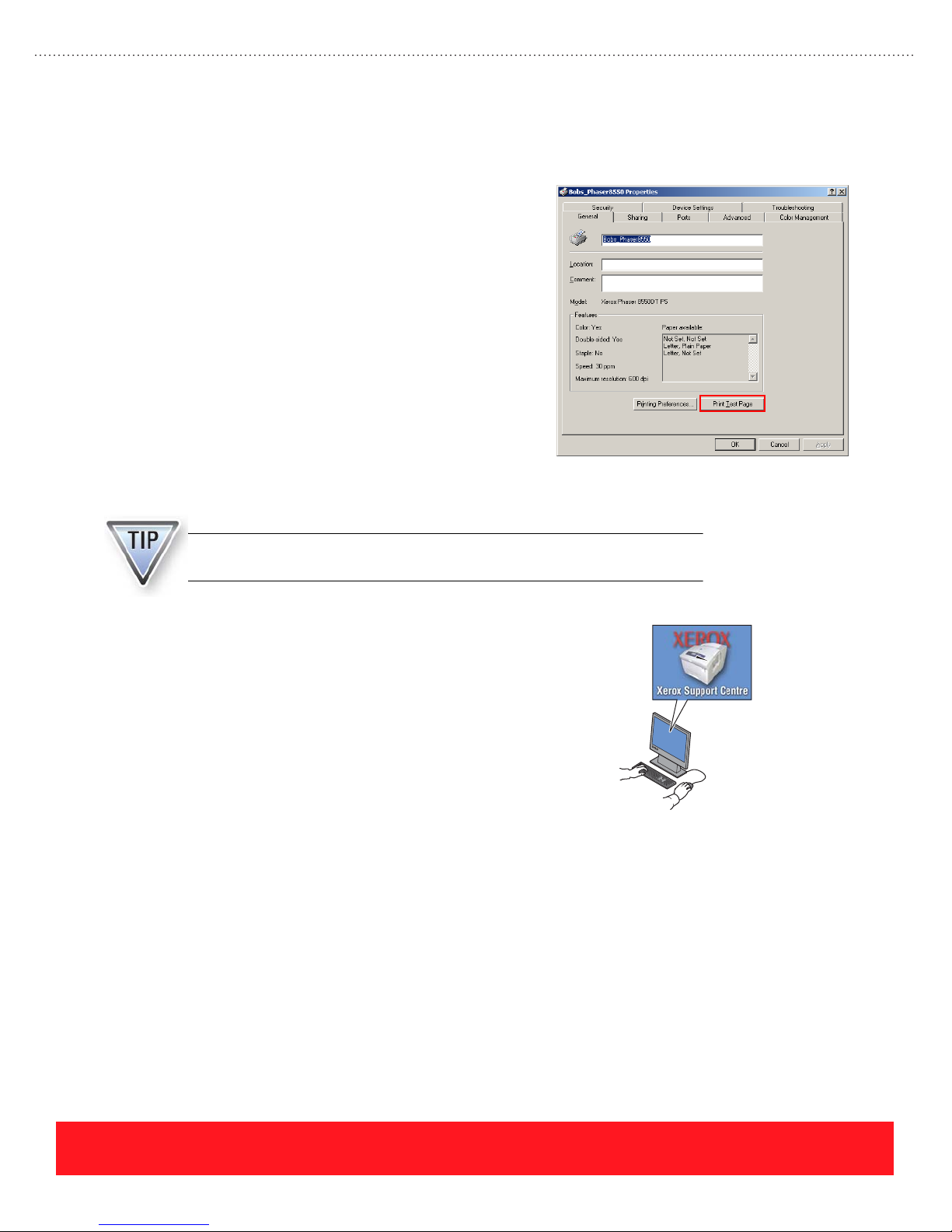
Print Jobs
To complete this step of the lab:
1. For each computer, open the printer Properties and
generate a test page. For example, click “Print Test
Page” as shown in the example to the right.
2. Use a common application such as Microsoft
®
Word
to generate jobs using the following printer
features (if available):
■ Select paper from Tray 1 and Tray 2
■ Two-sided printing (multi-page document)
■ Booklet printing (multi-page document)
■ Fast Color print-quality mode
■ Proof or Personal Print
Use the Xerox Support Centre
An Internet connection is required to access web-based resources using the
Xerox Support Centre for Phaser 8500 and 8550 printers.
®
1. If you installed a Phaser 8500 or 8550 printer driver, use
the shortcut icon on the computer desktop to open the
Xerox Support Centre utility.
2. Use the Xerox Support Centre to perform the following
tasks (no Internet connection required):
■ Use the “Supplies” tab to view information about the
supported paper
■ Use the “My Printer” tab to view the printer driver settings
■ Remove the paper from Tray 2 and view the Tray 2 status
indicator (left side of “Printer Status” area)
3. If an Internet connection is available, use the Xerox Support Centre to perform the following tasks:
■ Use the “My Printer” tab to launch CentreWare IS
■ Use the “My Printer” tab to view the service offerings for this printer
■ Use the “Troubleshooting” tab to launch the PhaserSMART troubleshooting tool
page 40
PHASER 8550, 8500, & 8400 SETUP SECTION
Version 1.0
Page 49
Install Upgrades
This section provides general information for installing upgrades and installation tips for
installing the memory DIMMs, hard drive (Productivity Kit), and configuration upgrades.
Instruction sheets are provided with the options and upgrades. When completing this section,
refer to training CD-ROM’s Resources section for electronic versions of the instruction sheets.
General Instructions
Closely follow the printed installation sheet that is packaged with each option and upgrade kit. Most
installations require access to the printer’s main board, which is located inside the electronics module.
The printer and upgrade components are static-sensitive. To avoid damage,
protect them from Electro-Static Discharge (ESD) during the installation by
using an approved ESD work surface and wrist strap.
The printer’s option plate must be removed to install memory DIMMs and the hard drive (Productivity Kit).
To remove the plate:
1. Turn the printer off.
2. Loosen the two thumbscrews located on the rear panel.
3. Lift the plate from the printer.
After installing an upgrade kit, always print the Configuration Page to verify
the printer recognizes the new hardware.
PHASER 8550, 8500, & 8400 SETUP SECTION
Version 1.0
page 41
Page 50
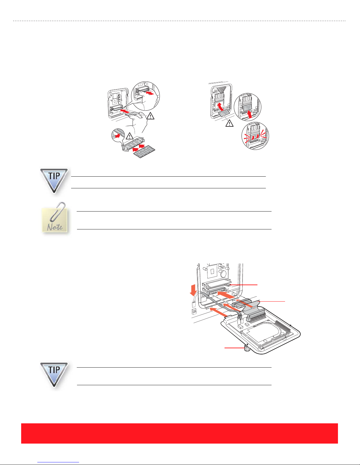
Memory Upgrade
3
Install an extra memory DIMM into the empty RAM slot. If each slot already contains a DIMM, remove the
lowest value DIMM and replace it with the DIMM included in the upgrade kit. Phaser 8400 printers support
128 MB and 256 MB DIMMs only. Phaser 8500 and 8550 printers also support 512 MB DIMMs.
4
Installing Phaser 8400 Memory Installing Phaser 8500/8550 Memory
Phaser 8400 and Phaser 8500/8550 memory DIMMs are not interchangeable.
Memory DIMMs are covered by the Xerox warranty, service agreement, or
Total Satisfaction guarantee only when purchased from Xerox.
Hard Drive (Productivity Kit) Upgrade
The hard drive (Productivity Kit) includes two
cables that must be installed on the Main Board. If
the lower RAM slot contains a memory DIMM, the
large cable is difficult to install. To improve access
for installing the cable, temporarily remove the
DIMM and then install the cable. After installing
both cables, install the DIMM (if removed) and use
the thumbscrews to secure the attached option plate.
The hard drive (Productivity Kit) comes preinstalled on an option plate. Save
the original plate for future use or discard it.
Lower RAM
DIMM Slot
Large Cable
Thumbscrew
page 42
PHASER 8550, 8500, & 8400 SETUP SECTION
Version 1.0
Page 51
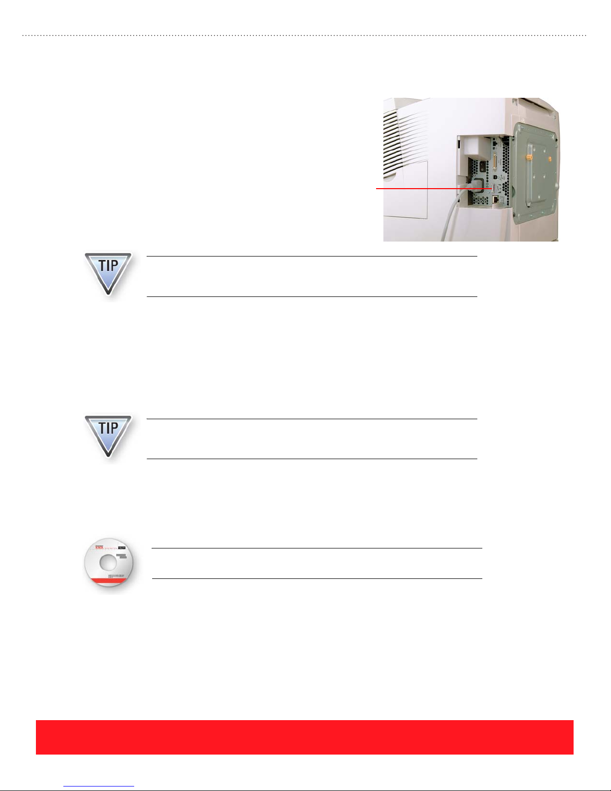
Configuration Upgrades
Configuration upgrade kits are available for
many Phaser 8400 printers, but not for
Phaser 8500 or 8550 printers. See
“Configuration Upgrades” on page 13 for a list
of the available kits and the parts needed for
upgrading printers. For most configuration
upgrades, the printer’s Configuration Card
must be replaced. This card is located behind
the interface cover as shown to the right.
Always print a Configuration Page before installing configuration upgrades.
Use the Configuration Page as a reference when reconfiguring the printer’s
network settings.
The Configuration Card defines the printer’s feature set and stores the printer’s network settings and Ethernet
address. After a Configuration Card is installed, the printer reads it at power-on to determine its feature set. If
the card already contains network settings, the printer implements those settings from the card. Refer to the
Knowledge Base or the Service Manual for a detailed list of parameters stored on the card.
Configuration
Card
After installing configuration upgrades, be sure to reinstall the printer driver. This step is especially important
for Phaser 8400DX upgrades to ensure the driver recognizes all the features of the new hard drive.
The Phaser 8400 printer’s Collation feature uses the hard drive only if the
printer driver’s feature set is configured for DX and the printer has the
DX-version Configuration Card.
Your Next Step
You have completed the Setup Section of the Self-Study Guide.
Return to the training CD-ROM and complete the Setup Self-Check. Then,
select the Care section on the CD-ROM to continue.
PHASER 8550, 8500, & 8400 SETUP SECTION
Version 1.0
page 43
Page 52

page 44
PHASER 8550, 8500, & 8400 SETUP SECTION
Version 1.0
Page 53

Phaser 8550, 8500, & 8400 Service Self-Study Guide
CARE SECTION
Prerequisites
❑ Care section of the
Phaser 8550, 8500, &
8400 Customer
Product Training
CD-ROM
Time To Complete
❑ Reading: 40 min.
❑ Video run time: 40 min.
❑ Exercises: 45 min.
❑ Optional labs: 45 min.
Equipment Checklist
❑ Phaser 8500/8550
User Guide or
Phaser 8400
Reference Guide
❑ Adobe
❑ Phaser 8550, 8500, or
®
8400 printer (optional)
Reader
®
Reference Manuals
Electronic copies of the
product manuals, guides,
and instruction sheets are
available from the
Resources section of the
training CD-ROM.
Care Objectives
■ Identify common causes and solutions for paper jams
■ Describe and replace the supplies
■ Resolve problems by cleaning or replacing parts
■ Describe the moving and repacking procedures
Complete the Care multimedia lessons on the training CD-ROM
before you begin this section of the Self-Study Guide.
This section of the Self-Study Guide presents information for resolving paper jams. It
describes the printer supplies as well as procedures for cleaning, replacing customer
parts, and moving the printer. Refer to the Phaser 8400 Reference Guide or the
Phaser 8500/8550 User Guide to complete the exercises in this section. Electronic
versions are available from the training CD-ROM’s Resources section.
Paper Jams
A variety of tools and resources are available to resolve paper jams. This
lesson describes the available resources and general techniques for
clearing jams. Hints and tips for clearing jams at specific printer locations
are also provided.
Resources
The printer provides a variety of
resources at the Control Panel to help
users resolve paper jams:
■ Troubleshoot Jams menu and
Help or Information button
provide instructions for
clearing jams
■ 3-dimensional, animated
graphics show jam locations
PHASER 8550, 8500, & 8400 CARE SECTION
Version 1.0
AnimatedTroubleshoot Jams
Menu Graphic
Phaser 8400
PAPER JAM - OPEN FRONT COVER
TO CLEAR
PRESS i
Troubleshoot Jams
About This Job
Walk-Up Features
Printer Identification
Help or Information Button
page 45
Page 54
Additional tools for clearing and troubleshooting jams include the following:
Tool Function
Quick Reference Guide This manual is located in the printer’s documentation pocket and provides a list
of supported papers and visual instructions for clearing jams.
Paper Jams menu The menu Troubleshooting...Paper Jams provides the embedded Paper Tips
Service Tools menu The menu Troubleshooting...Service Tools provides access to the embedded
PrintingScout If connected to a network via TCP/IP, PrintingScout displays a message on the
PhaserSMART &
knowledge base
Internet Links
(Phaser 8400 only)
Xerox Support Centre
(Phaser 8500 & 8550 only)
General Techniques
Observe the following techniques for clearing jams regardless of the location within the printer:
■ Never use sharp or metal objects - sensitive components such as the Drum and Transfix Roller
can be scratched, causing permanent print-quality defects.
Page, online jam prevention tips, and a Paper Path Test for checking the
functionality of each tray.
Printer Status Page, Jam History, and the Customer Diagnostics Mode.
user’s computer screen when paper jams and other problems occur. The
message includes a link to instructions for solving the problem.
Use PhaserSMART and the knowledge base to access online support.
Windows users can access the Phaser 8400 user documentation and videos for
clearing jams from the Internet using the menu path Start...Programs...Xerox
Office Printing. Loading the printer driver adds this item to the Start menu.
Phaser 8500 and 8550 users can access the User Guide and videos for
clearing jams from the Xerox Support Centre utility.
page 46
■ Verify the media is supported - if possible, print the Paper Tips Page for a list of supported media
and guidelines for using the trays. You may also refer to the Reference Guide for supported paper
types and sizes.
■ Remove paper in the direction of travel - when possible, pull the paper in the direction it
normally travels through the paper path to avoid damaging internal components.
When the Control Panel displays a paper jam message on Phaser 8500 and
8550 printers, press Help to view the jam code.
Photographs in the following section show green parts for all customer
touch points such as the Paper Release Guide and Exit Guide. Green parts
are installed on Phaser 8400 printers while Phaser 8500 and 8550 printers
use white parts with green labels.
PHASER 8550, 8500, & 8400 CARE SECTION
Version 1.0
Page 55
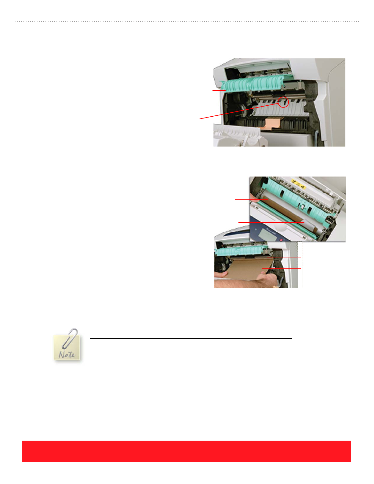
Jams Behind Front Cover
Use the following hints and tips when
clearing jams behind the Front Cover:
■ Remove all visible paper.
■ Verify the Deskew Sensor is
present and moves freely.
■ Clean the Feed Rollers only if
they are visibly dirty.
■ To improve clearance, lift the
paper guide until it snaps into
place as shown to the right.
Jams Inside Preheater
If paper scraps are located inside the Preheater,
use the following procedure to remove them:
1. Open the Front Cover and Exit Cover.
2. Lift the Paper Guide and snap it into
the “up” position, as shown to the
right.
3. Insert a sheet of card stock just below
the metal Deskew Roller (see example
for location).
4. In the exit area, rotate the Paper
Release Guide away from the Drum.
Paper Guide
(in raised
position)
Deskew
Sensor
Card Stock
Paper Scrap
Deskew Roller
Card Stock
5. Watch the exit area while gently pushing the card stock through the Preheater.
6. Remove the scraps pushed through by the card stock.
7. Remove the card stock from the printer.
If you are unable to push the card stock through the Preheater, use card stock
that is thin enough to fit between the Transfix Roller and Drum.
PHASER 8550, 8500, & 8400 CARE SECTION
Version 1.0
page 47
Page 56
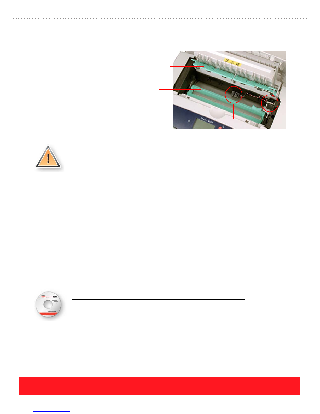
Exit Jams
To clear and resolve jams under the Exit
Cover:
■ Check for paper below both
■ Check for damaged sensors and
■ If necessary, clean the exit rollers.
■ If the paper sticks to the Transfix
Jams At Trays
Use the following hints and tips to resolve jams that occur from one tray:
■ Verify the guides are adjusted properly for the paper size.
■ Verify the paper in the tray matches the printer driver settings.
Exit Guide
the Exit Guide and the Paper
Release Blade.
Paper
sensor flags (two visible).
Release
Blade
Roller, clean all the scraps and
residue from the roller to avoid
repeating print-quality defects.
Never use Phaser 860 and 8200 Glossy Paper with Phaser 8400 printers,
because the coating sticks to the Transfix Roller.
Sensors
■ For jams at the 525-sheet trays:
■ Make sure the Pick Roller is properly installed (both sides snapped into place and rotated above the
release latch)
■ Clean or replace the Pick Roller and Retard Roller
■ For jams at the Tray 1 (MPT):
■ Clean the Pick Roller and Pick Pad
■ Replace the Front Door and Tray kit
Return to the training CD-ROM and select Supplies to continue.
page 48
PHASER 8550, 8500, & 8400 CARE SECTION
Version 1.0
Page 57

Supplies
Ink Sticks
This lesson describes the
printer supplies, which
include the ink sticks and
Ink Stick
1
2
3
4
Maintenance Kits. Supplies
for Phaser 8400 printers are
not interchangeable with Phaser 8500 and
8550 supplies.
Ink sticks are the only consumable while
Maintenance Kits are routine maintenance
items. An exercise for troubleshooting
Maintenance Kit
problems with printer supplies is included.
Genuine Xerox Solid Ink 8400 ink sticks are shaped-coded to fit only the Phaser 8400 ink loader. Genuine
Xerox Solid Ink 8500/8550 is compatible only with the Phaser 8500 and 8550 printers. Each color is clearly
marked with a number that corresponds to the correct ink-loading bin.
Ink sticks shipped with the printers currently do not have the Xerox logo as
shown above. Do not mistake Xerox ink without the Xerox logo for non-Xerox
ink (NXI).
Life Expectancy
The life expectancy of each ink stick depends on the percentage of coverage per page. At 5% coverage per
color, the life expectancy is approximately 1,100 pages per Phaser 8400 ink stick. Each Phaser 8500/8550 ink
stick has a life expectancy of approximately 1000 pages at 5% average coverage.
Optimizing Ink Usage
Customers can observe the following practices to optimize ink usage:
■ Use Fast Color or Standard Print-Quality modes
■ Print low coverage, text-only documents
■ Avoid unnecessary Printhead cleaning cycles:
■ Leave the power turned on
■ Keep the covers and doors closed
To conserve ink, the printer does not perform a Printhead cleaning cycle after it
exits standby mode. The printer may automatically clean its Printhead if allowed
to cool by leaving doors or covers open or by turning off the power switch.
PHASER 8550, 8500, & 8400 CARE SECTION
Version 1.0
page 49
Page 58

Reporting Ink Level Status
After the “ink low” message is displayed, the printers can make about 1000 more prints at 5% coverage of the
low color before displaying “ink out”. The printers have several ways to report the ink level status:
■ Control Panel status messages for ink low and ink out (Phaser 8500 and 8550 printers indicate
which color is out, while Phaser 8400 printers do not)
■ Windows printer driver Paper/Quality properties page (status window)
■ CentreWare IS Status page
■ If connected via TCP/IP, PrintingScout reports when ink is out
Phaser 8400 printers indicate ink is low
when any color reaches the center of the
last oval hole in the ink load bin, where
the “ink low” sensor is located. When ink
is out, the ink sticks for one or more colors
are below the bottom of the hole. In the
Ink Low
Sensor
example to the right, yellow and black are
low while magenta is out of ink.
Ink Out
Phaser 8400 Ink Levels
On Phaser 8500 and 8550 printers, users
should add any color that is below the
“ink low” sensor. These printers have
individual “ink out” sensors for each ink
stick color, so the Control Panel can
indicate which color is out.
Ink Low
Sensor
Phaser 8500/8550 Ink Levels
page 50
PHASER 8550, 8500, & 8400 CARE SECTION
Version 1.0
Page 59
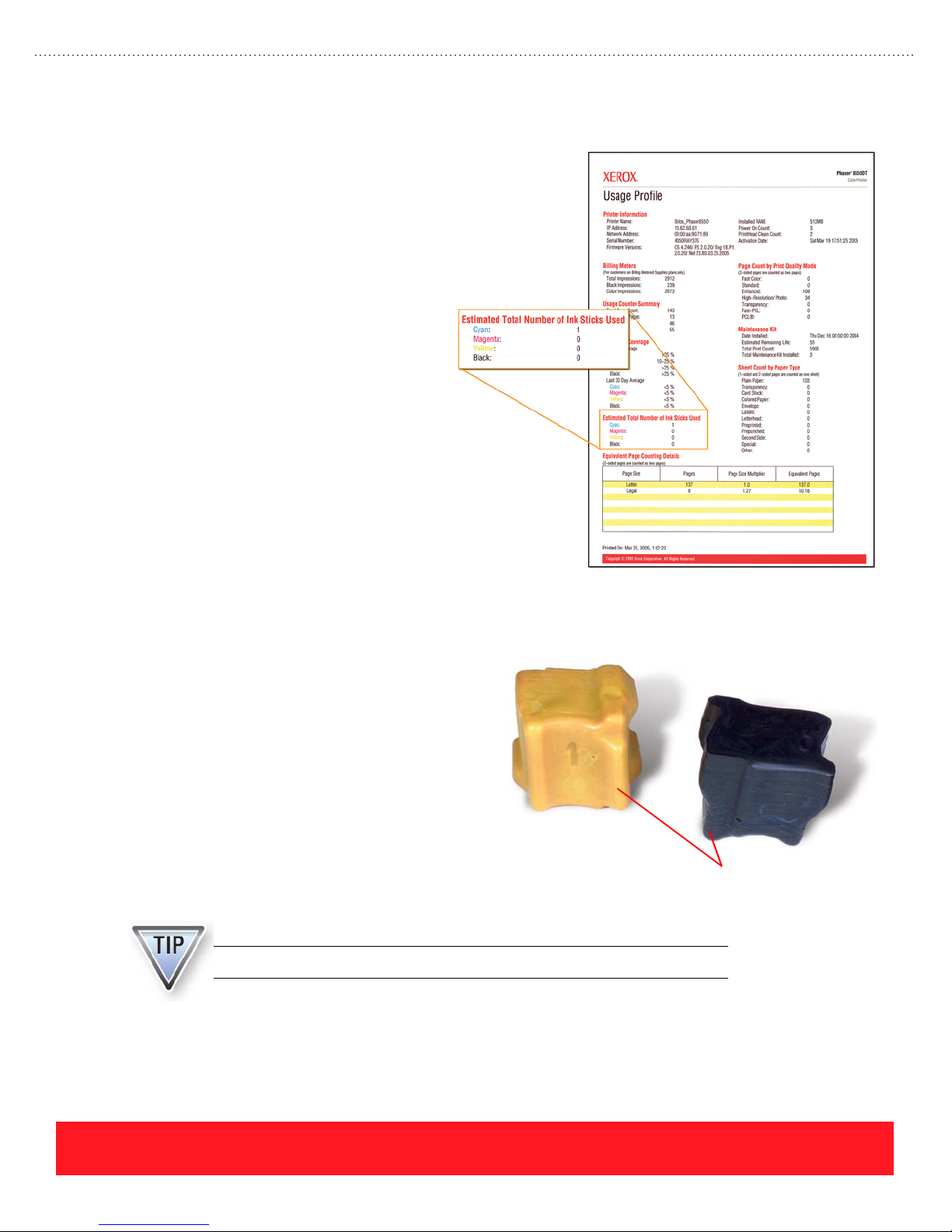
Determining Actual Usage
Customers can print the Usage
Profile or Printer Status Page to view
information on ink consumption.
These pages indicate the average
coverage over the past 30 days and
during the life of the printer.
A field on the Phaser 8500/8550
Usage Profile (shown to the right)
provides the actual count of the ink
sticks used for each color. The
Phaser 8400 Usage Profile does not
provide the ink stick count. Because
Phaser 8500 and 8550 printers have
“ink out” sensors for each color, they
are capable of counting the number
of inks sticks used. In contrast,
Phaser 8400 printers have one “ink
out” sensor that monitors all four
colors of ink.
Counting Ink Sticks
A notch on each Phaser 8500/8550 ink stick
triggers an “ink out” sensor flag in the Ink
Loader Assembly, allowing the printers to
count ink sticks as they are used. If the printer
fails to detect a new ink stick after it
calculates approximately 2.5 ink sticks of that
color should have been melted, it displays an
error within the range 9,035.xx to 9,038.xx.
Loading chipped or broken ink sticks that do
not have the notch can cause the error. Other
possible causes include using non-Xerox inks
(NXI) that do not have the notch or a failed
Ink Loader Assembly.
Only Phaser 8500 and 8550 printers can count ink stick usage.
Bottom View
Notch For Sensing Ink Stick Count
Side View
PHASER 8550, 8500, & 8400 CARE SECTION
Version 1.0
page 51
Page 60

Maintenance Kits
The Maintenance Kit contains the oil-saturated roller and the wiper blade for oiling the Drum. It also contains
a counter that tracks the kit usage.
New printers include the Standard-Capacity
Maintenance Kit, but Standard- and
Extended-Capacity kits are available for Phaser
8400 and 8550 printers. Although the Phaser 8400
and 8500/8550 Maintenance Kits look the same,
they are not interchangeable. Users can
differentiate between Phaser 8400 and Phaser
8500/8550 kits by looking for the printer model
on the label shown to the right. The label on
Phaser 8400 Maintenance Kits does not include
the printer model.
Life Expectancy
Phaser 8500/8550
Printer Model
Phaser 8500 printers support only the Standard-Capacity Maintenance Kit.
Phaser 8400 and 8550 printers support both the Standard- and
Extended-Capacity kits. Phaser 8400 kits and Phaser 8500/8550 kits are not
interchangeable.
The life expectancy depends on the printer model and capacity of the kit. For example, the Standard-Capacity
Kit for Phaser 8500/8550 printers can produce approximately 10,000 black & white prints or 5,500 color
prints. Most Standard kits will produce between 5,500 and 10,000 prints because users print a combination of
color and black & white pages. In contrast, the life expectancy for Standard Phaser 8400 Maintenance Kits is
10,000 prints regardless of the colors used.
Extended-Capacity Maintenance Kits for Phaser 8400 and Phaser 8550 printers both have a life expectancy
of 30,000 pages up to 20% coverage and 20,000 pages when coverage exceeds 20%. Phaser 8500 printers do
not support the Phaser 8550 Extended-Capacity kit. Refer to the chart below for details.
Total Coverage
Maintenance Kit
Standard-Capacity
(Phaser 8400)
Standard-Capacity
(Phaser 8500 and 8550)
Extended-Capacity
(Phaser 8400 and 8550)
The Phaser 8500 and 8550 values are estimates based on Letter-size pages.
Printing on paper that is larger than Letter-size can affect Maintenance Kit
life expectancy. See “Determining Actual Usage” on page 53 for details.
Up to 20% 20 to 100%
10,000 pages 10,000 pages
10,000 pages black & white
5,500 pages color
30,000 pages 20,000 pages
10,000 pages black & white
5,500 pages color
page 52
PHASER 8550, 8500, & 8400 CARE SECTION
Version 1.0
Page 61

Reporting Maintenance Kit Status
The printers track their Maintenance Kit status including the life remaining and installation date of the
current kit, as well as the total number of kits installed. Kit status can be reported accurately after used kits
are installed, because each kit includes a counter to track usage. The printers have several ways to inform
users of the Maintenance Kit status:
■ The Control Panel displays status messages for low and replace
■ Windows printer driver Paper/Quality properties page (status window)
■ The CentreWare IS Status page provides status information
■ If connected via TCP/IP, PrintingScout reports when the Maintenance Kit is low or expired
The Maintenance Kit is “low” when less than 1000 pages remain.
Determining Actual Usage
Customers can use the Control Panel to view information about the Maintenance Kit. The installation date,
estimated life remaining, and type of kit installed can be determined by selecting the Information menu and
then the Supplies Info menu. Similar information is available by printing the Usage Profile or the Printer
Status Page.
A feature of the Phaser 8500 and 8550 Usage
Profile is the “Equivalent Page Counting
Details” field. It provides the multiplication
factors used by the printer to determine how
much oil is consumed for different types of
jobs. This information can be used to help
customers understand why their Maintenance
Kit produced fewer pages than expected.
In the example to the right, the printer used a
page size multiplier of 1.27 for Legal-size
pages. Generating prints on Legal-size paper
will consume the Maintenance Kit 1.27 times
faster than using Letter-size paper.
Phaser 8500 and 8550 Usage Profile
PHASER 8550, 8500, & 8400 CARE SECTION
Version 1.0
page 53
Page 62

Maintenance Kit Lab
If a printer is available, complete this lab to check the printer’s Maintenance Kit status and to
perform the Maintenance Kit replacement procedure. Use the following procedure to determine
the Maintenance Kit status:
1. Select the Information menu and press OK.
2. Scroll to Supplies Info and press OK.
3. Select Maintenance Kit Life and press OK.
The percent remaining and installation date are normally displayed. If less
than 1000 pages remain, the display provides the number of pages instead of
percent remaining.
An instruction sheet is packaged with each Maintenance Kit. An electronic version is available from the
training CD-ROM’s Resources section. If a printer is available, perform the following steps to become
familiar with the replacement procedure:
1. Open the Side Door.
The printer cannot detect when the Side Door is open. If a print cycle begins,
the Maintenance Kit rotates up to oil the Drum. Allow the print job to finish
before removing the Maintenance Kit.
2. Pull out the Maintenance Kit.
3. Normally you would discard the kit or return it to Xerox for recycling. For this lab, reinstall the kit.
4. Close the Side Door.
Troubleshooting Exercise
The Printer Status Page and Usage Profile provide important information for troubleshooting
ink and Maintenance Kit issues. Use the example Phaser 8400 Printer Status Page on the next
page to diagnose the following customer examples:
The answers for this exercise are located in the Appendix on page 90.
1. On November 11, 2003, a customer explains that their printer is using too much ink. The printer’s
warranty period began August 30, 2003. Based on the Printer Status Page, what advice would you
offer the customer? _____________________________________________________________
2. On October 29, 2003, a customer contacts you regarding print-quality problems caused by their
Standard-Capacity Maintenance Kit. Use the information on the Printer Status Page to determine
if the kit has failed during the warranty period. _______________________________________
3. Is average ink coverage during the last 30 days greater than or less than 20%? ______________
page 54
PHASER 8550, 8500, & 8400 CARE SECTION
Version 1.0
Page 63

4. What advice would you give a customer who has ordered more cyan ink because her printer ran
out of cyan, but she has an immediate need to print a draft copy of her document? ___________
_____________________________________________________________________________
5. Before authorizing onsite service, the knowledge base indicates the Maintenance Kit should be
replaced to correct a specific print-quality problem. The customer has FAXED a copy of their
Printer Status Page, and they are certain someone in the office installed a new kit. Use the Printer
Status Page to determine if the kit has actually been replaced:
After completing this exercise, return to the Care section of the Phaser 8550,
8500, & 8400 Product Training CD-ROM and select Troubleshooting to continue.
________________________
PHASER 8550, 8500, & 8400 CARE SECTION
Version 1.0
page 55
Page 64
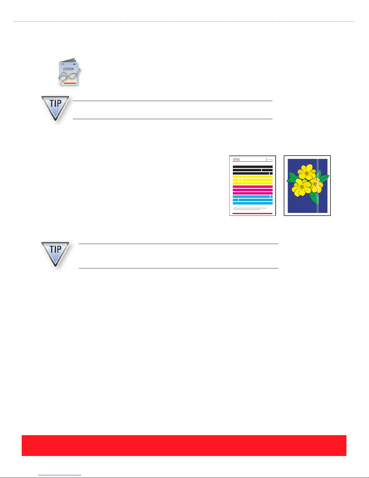
Cleaning
Most print-quality and paper feed problems are caused by damaged or unsupported media. If the
media is OK, cleaning is often the next step in the troubleshooting process. This section presents
examples of the most common print-quality problems and related cleaning procedures. Always
use the embedded Troubleshooting Print Quality Page to determine if cleaning is required.
Cleaning instructions are located in the knowledge base, the Phaser 8400
Reference Guide, and the Phaser 8500/8550 User Guide.
Eliminate Light Stripes
The automated Printhead cleaning sequence should be used
when weak or missing jets cause print-quality problems, as
shown to the right. In this example, the Light Stripes Test
Print is missing several jets while the sample customer print
shows the affect of a single missing jet.
The most common way to restore weak or missing Printhead
jets is to run the automated “Eliminate Light Stripes”
cleaning procedure on Phaser 8400 printers. Phaser 8500 and
8550 printers have an Eliminate Light Stripes menu that
provides three choices for cleaning the Printhead.
Light Stripes Test
Light Stripes
Test P rint
Customer Print
Each missing jet generates a light vertical band that is approximately 4 mm
(1/6 inch) wide on printed images, because the jet is interlaced with several
other jets during the print process.
Phaser 8400 Printhead Cleaning
The Control Panel is used to begin the Printhead cleaning sequence, which takes about five minutes. For
Phaser 8400 printers, use the following procedure to select the “Eliminate Light Stripes” cleaning sequence.
If a printer is available, locate the procedure on the Control Panel but do not run the sequence unless you
want to clean the Printhead.
1. Select Troubleshooting and press OK.
2. Scroll to Print Quality Problems and press OK.
3. Locate the Eliminate Light Stripes selection in the menu. Do not select “Eliminate Light Stripes”
unless you want to clean the Printhead.
page 56
PHASER 8550, 8500, & 8400 CARE SECTION
Version 1.0
Page 65

After the cleaning procedure, the printer produces
the Cleaning Page and the Light Stripes Test Page.
The Light Stripes Test Page may show a small
amount of discoloration, as shown to the right, but
all the jets should have produced solid color bars.
The discoloration will clear up after a few prints
are generated.
The printer’s default Print-Quality
Mode affects the brightness of the
color bars on the Light Stripes Test
Page. When the Print-Quality Mode is
Enhanced (factory default) or High
Res/Photo, the colors are highly
saturated. Test prints generated using
the Fast Color or Standard Modes
have color bars with less saturation, as
shown to the right.
When resolving print-quality issues,
select Enhanced Mode as the printer
default before printing the Light
Stripes Test Page. Otherwise, the low
color saturation can be mistaken for
problems with the printer.
Cleaning Page
Fast Color or
Standard Modes
Light Stripes Page With
Slight Discoloration
Enhanced or
Photo Modes
PHASER 8550, 8500, & 8400 CARE SECTION
Version 1.0
page 57
Page 66
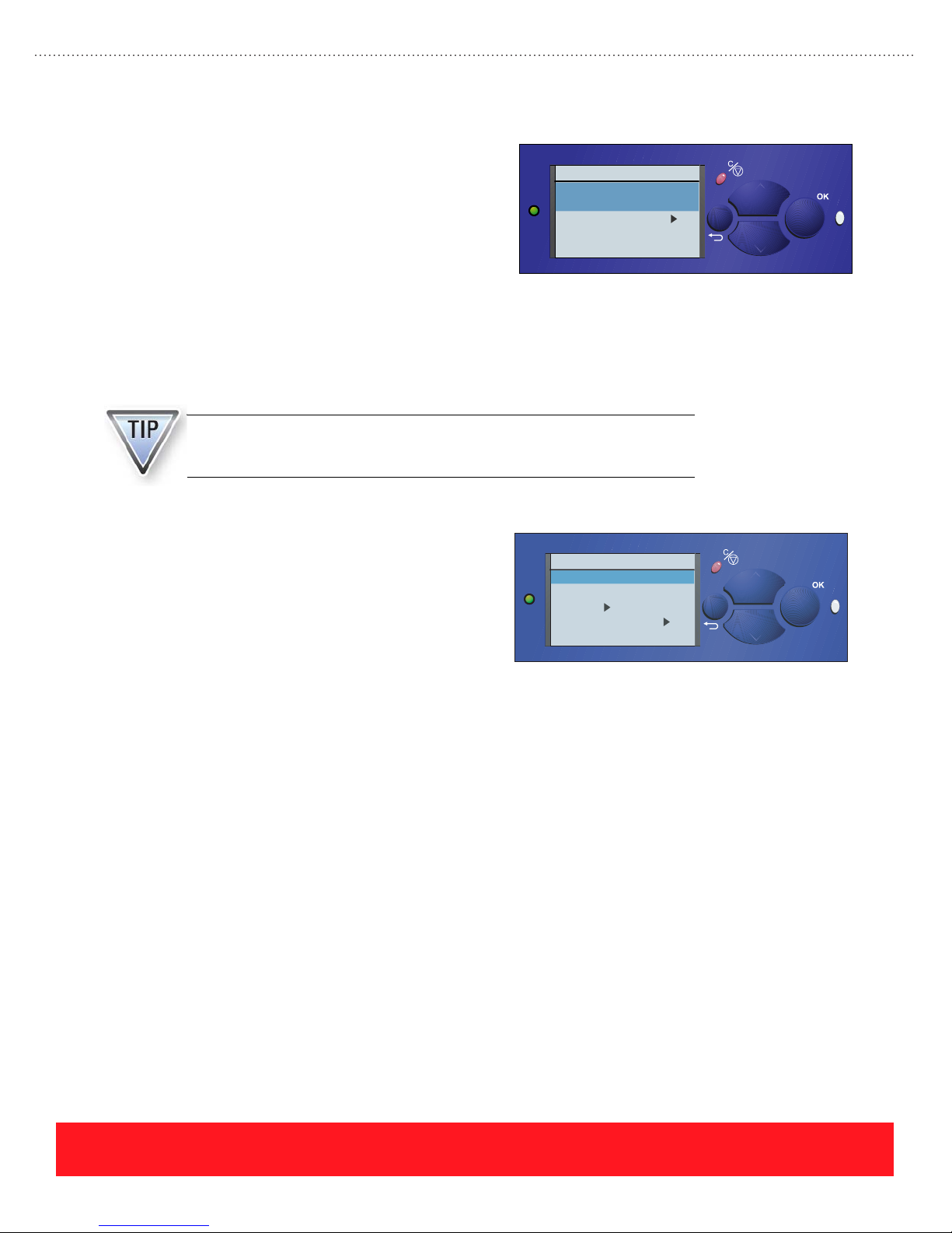
Phaser 8500 and 8550 Printhead Cleaning
Three modes are available in the Phaser 8500/8550
Phaser 8550
menu system to resolve weak or missing jets. When
customers experience light stripes caused by weak or
missing jets, they should select the menu path
Troubleshooting…Print Quality Problems and print
the Troubleshooting Print Quality Page (menu choice
shown to the right). The step-by-step instructions on
Print Quality Problems
Troubleshooting Print
Quality Page
Eliminate Light Stripes
Remove Print Smears
Exit
6350DT
this page are not the same as the cleaning instructions
for Phaser 8400 printers.
Engineering has recently updated the Phaser 8500 and 8550 procedure to delete the 4-hour cool down step,
even though this step appears on the Troubleshooting Print Quality Page. Testing has shown that the 4-hour
cool down rarely recovers problem jets.
The procedures for troubleshooting weak or missing jets on Phaser 8400
printers are not the same as for Phaser 8500 and 8550 printers. Always refer
to the knowledge base for the most up-to-date procedures.
?
When directed by the troubleshooting instructions,
Phaser 8550
users can enter the Eliminate Light Stripes menu to
select choices including “Basic,” “Advanced,” and
“Jet Substitution” for restoring print-quality. The menu
also includes the Light Stripes Test Page, as shown to
the right.
Eliminate Light Stripes
Light Stripes Test
Basic
Advanced
Jet Substitution Mode
Exit
6350DT
?
Basic Cleaning
The “Basic” choice in the Phaser 8500/8550 Eliminate Light Stripes menu runs the same Printhead cleaning
sequence that is available on Phaser 8400 printers. When a printer has weak or missing jets, run the “Basic”
cleaning sequence two consecutive times before trying the “Advanced” mode.
page 58
PHASER 8550, 8500, & 8400 CARE SECTION
Version 1.0
Page 67
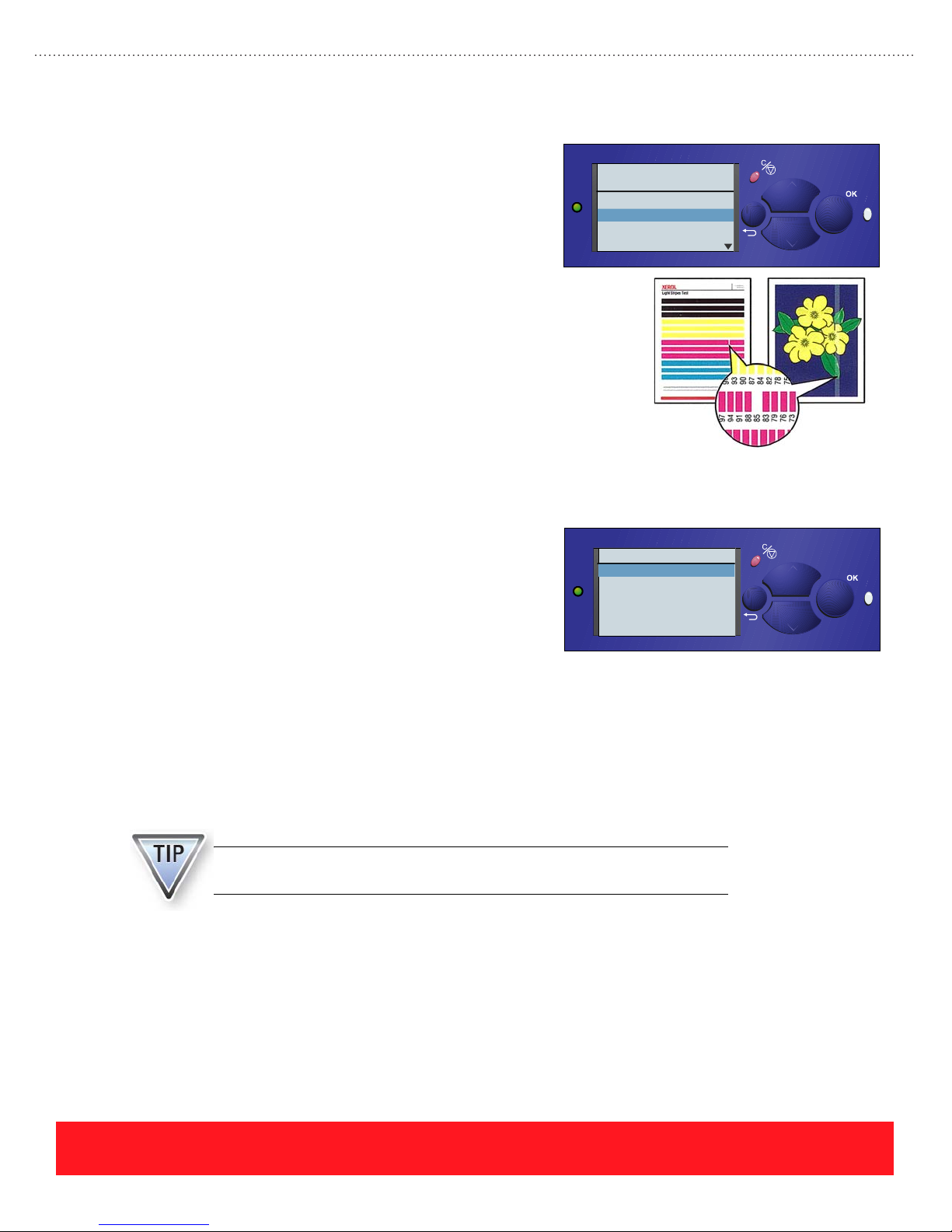
Advanced Cleaning
After selecting “Advanced” the user is prompted to
choose the color and number of the problem jet
based on the Light Stripes Test Page. In the
print-quality example to the right, the user should
select magenta jet number 85. After selections are
made, the printer temporarily increases the drive
voltage to the selected jet, prints several pages, and
then performs the cleaning sequence.
The Advanced cleaning process is similar to the
process associated with downloading the “JetFix”
snippet to Phaser 8400 printers. (See Service
Bulletin 640 for details.) However, a snippet is not
required for Phaser 8500 and 8550 printers because
the feature is embedded in the printer’s firmware.
Jet Substitution
Phaser 8550
Select the color of the
weak or missing jet
Cyan
Magenta
Yellow
Black
6350DT
?
Phaser 8400, 8500, and 8550 printers all provide Jet
Phaser 8550
Substitution mode. However, Phaser 8500 and 8550
models feature two important differences:
■ Phaser 8500/8550 Jet Substitution mode can
provide an end solution instead of serving as
Jet Substitution Mode
Cyan
Magenta
Yellow
Black
Exit
6350DT
a temporary fix as for Phaser 8400 printers.
■ Most Phaser 8500/8550 users will not notice changes to print-quality or speed when using the Jet
Substitution mode. It may increase the imaging time one or two seconds per page, which is a much
smaller impact on print speed than the Phaser 8400 Jet Substitution mode.
Because Jet Substitution mode can provide an end solution, it is located in the “Eliminate Light Stripes”
menu instead of requiring a hidden push button sequence, as is the case with Phaser 8400 printers. The
knowledge base provides procedures for determining when to use Jet Substitution mode. Factors such as the
use of “Billing Meters” or three or more adjacent jets of the same color can affect the recommended solution.
Always refer to the knowledge base to determine when it is appropriate to use
Jet Substitution mode as an end solution.
?
PHASER 8550, 8500, & 8400 CARE SECTION
Version 1.0
page 59
Page 68
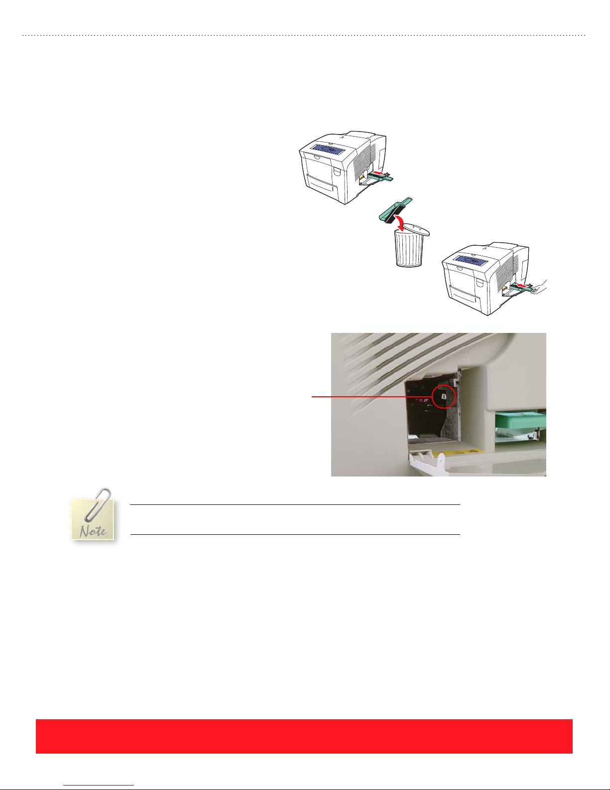
Empty The Waste Ink Tray
After running the Printhead cleaning sequence, the printer may display “Waste Tray Full”. Use the following
procedure to empty the Waste Tray:
1. Open the Side Door.
2. Pull out the Waste Tray.
3. Twist the tray slightly to loosen the
ink and discard the waste ink as
normal office waste.
4. Insert the tray into the printer.
5. Close the Side Door.
The printer moves the Printhead Wiper
Assembly up from its home position to lock the
Waste Tray in place. Occasionally, it may be
necessary to remove the tray while it is locked.
To remove the Waste Tray when
locked, first remove the
Maintenance Kit. Locate the white
release lever just inside the Side
Door, shown to the right. Push down
on the release lever to manually
unlock the tray.
Waste Tray
Release Lever
After the cleaning cycle, the printer locks the Waste Tray for several minutes
until the waste ink has cooled.
page 60
PHASER 8550, 8500, & 8400 CARE SECTION
Version 1.0
Page 69
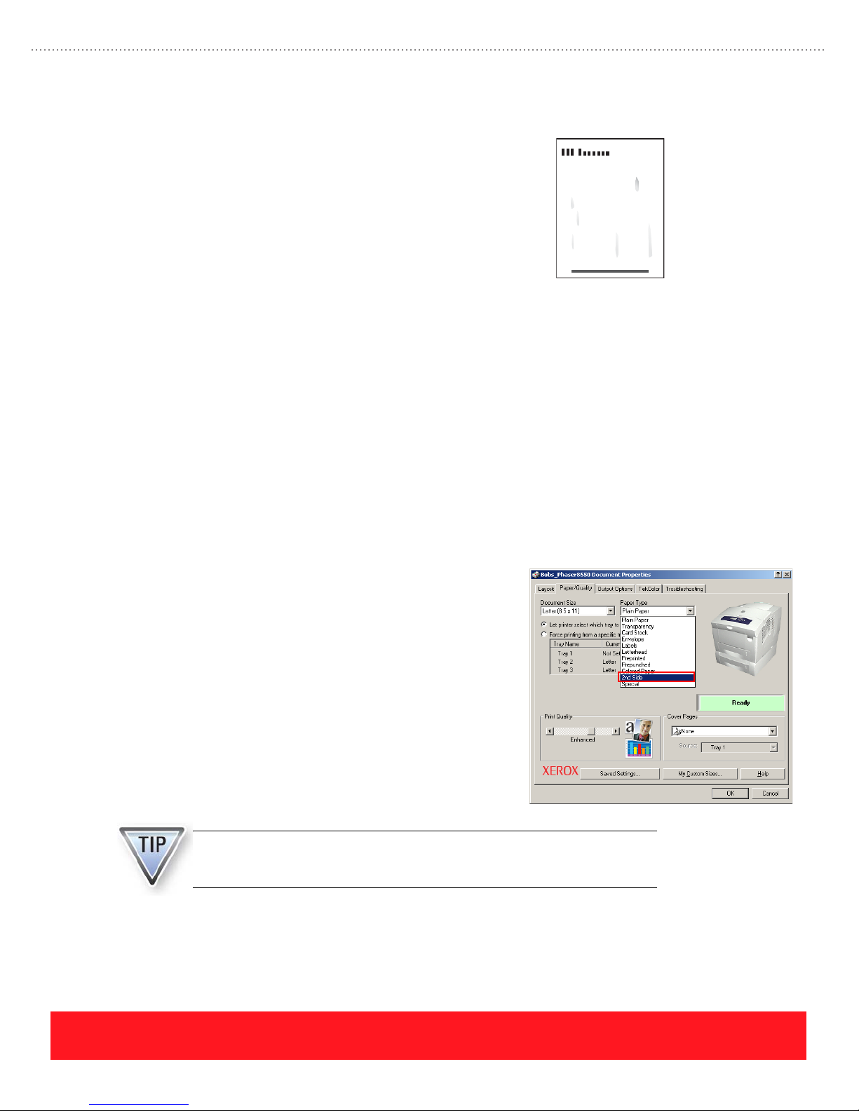
Remove Print Smears
The automated Remove Print Smears sequence cleans the
paper path when ink or other debris builds up and causes
print-quality problems, as shown to the right. This procedure
removes ink that can become lodged inside the Preheater, as
well as ink that accumulates on the Paper Feed Rollers.
Approximately 15 sheets of clean paper are used when
running this procedure, which takes about 5 minutes. On
Phaser 8500 and 8550 printers, a special paper type option
called “2nd Side” can be selected to resolve smearing
problems when generating manual duplex prints.
Paper Path Cleaning
The same Control Panel sequence is used to run the Remove Print Smears sequence on Phaser 8400, 8500,
and 8550 printers. If a printer is available, use the following procedure to locate the procedure, but do not
begin the sequence unless you want to clean the paper path:
1. Select Troubleshooting and press OK.
2. Scroll to Print Quality Problems and press OK.
3. Locate the Remove Print Smears selection in the menu. Do not select Remove Print Smears
unless you want to clean the paper path.
Example Page With Ink Smears
2nd Side Paper Type Option
The “2nd Side” paper type option is intended for resolving
problems associated with manual duplex jobs on Phaser
8500 or 8550 printers.
If users report ink smearing
problems when manually duplexing, instruct them to
select “2nd Side” as the paper type. This mode causes the
printer to separate the preheater plates when each page is
generated.
Keep in mind that users must first clean their printer’s
paper path to resolve the smearing or smudging problem.
After the print-quality has been restored, selecting “2nd
Side” as the paper type will avoid smearing that could
otherwise occur on subsequent prints.
If smearing or smudging occurs when using automatic two-sided printing,
clean the paper path guides to remove ink build-up that can cause
print-quality problems.
PHASER 8550, 8500, & 8400 CARE SECTION
Version 1.0
page 61
Page 70
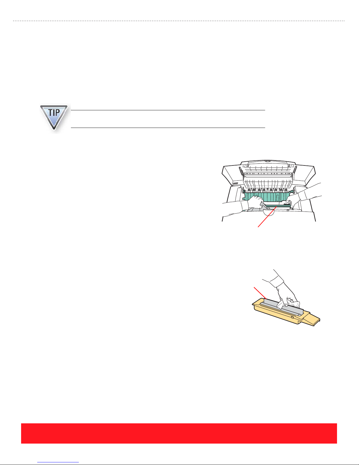
Clean Components Manually
When the automated cleaning procedures fail to resolve print-quality or paper feed problems, the following
components may require manual cleaning:
■ Paper Release Blade
■ Maintenance Kit Wiper Blade
■ Paper Pick, Feed, and Exit Rollers
Use a lint-free cloth soaked with 90% isopropyl alcohol when cleaning printer
components.
Paper Release Blade
The Paper Release Blade may accumulate ink or other
debris, leaving smears or vertical streaks on the page. To
clean the blade:
1. Open the Exit Cover.
2. Using the handle, carefully rotate the blade upward.
3. Use 90% isopropyl alcohol on a lint-free cloth
and wipe the front and back sides of the flexible
blade as shown to the right.
4. Rotate the blade so it rests on the Drum.
5. Close the Exit Cover.
Paper Release
Blade
page 62
Maintenance Kit Wiper Blade
The Maintenance Kit Wiper Blade may accumulate ink or
other debris, causing improper drum oiling that results in
print-quality problems. To clean the blade:
Maintenance
Kit Wiper Blade
1. Open the Side Door.
2. Remove the Maintenance Kit.
3. Use 90% isopropyl alcohol on a lint-free cloth
and wipe the front and back sides of the flexible
blade as shown to the right.
4. Reinstall the Maintenance Kit.
5. Close the Side Door.
Clean Paper Pick, Feed, & Exit Rollers
The Paper Pick, Feed, and Exit Rollers may accumulate ink that smears on the paper. Accumulations of paper
dust may cause the rollers to slip and cause paper jams. To clean the rollers, always refer to the knowledge
base for the latest cleaning procedures.
PHASER 8550, 8500, & 8400 CARE SECTION
Version 1.0
Page 71
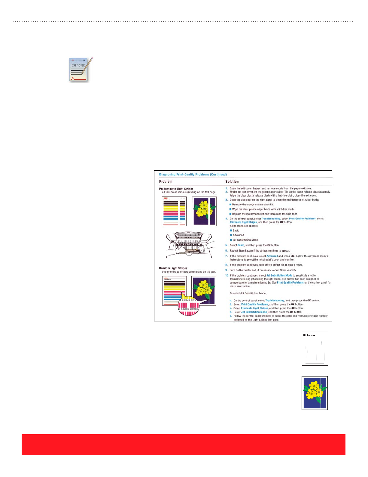
Cleaning Review Exercise
Refer to the Random Light Stripes procedure from the partial Phaser 8500/8550 Troubleshooting
Print Quality Page to answer the first questions.Then, select the cleaning procedure that is most
likely to resolve the associated problem.
The answers for this exercise are located in the Appendix on page 91.
1. According to the Phaser 8500/8550 Troubleshooting Print Quality Page, how many times should
users select “Basic” before they should select “Advanced” from the Eliminate Light Stripes menu?
(a) 1(b) 2(c) 3(d) 4
2. Which troubleshooting step should not be used even though it appears on the embedded
Phaser 8500/8550 Troubleshooting Print Quality Page?
(a) Step 1 (b) Step 2 (c) Step 3 (d) Step 8
3. A hidden push button sequence is used to select Jet Substitution mode on Phaser 8500/8550 printers.
(a) True (b) False
“Diagnosing Print-Quality
Problems” Procedure
from the Phaser 8500/8550
Troubleshooting Print
Quality Page
4. When the print-quality problem depicted to the
right occurs, which part of the printer should be
cleaned?
5. When the print-quality problem depicted to the
right occurs, which part of the printer should be
cleaned?
PHASER 8550, 8500, & 8400 CARE SECTION
Version 1.0
A. Maintenace Kit Wiper
B. Tray 2 Pick Roller
C. Paper Path
A. Printhead
B. Exit Rollers
C. Preheater
page 63
Page 72
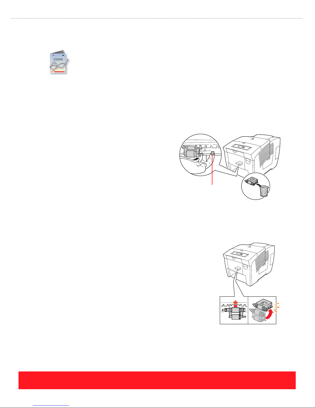
Replace Parts
2
■ Feed Roller Kit
■ Front Cover and Tray
Then, review the following hints and tips for replacing each assembly.
Feed Roller Kit
Customers can replace printer components, including the Pick Roller/Retard Roller and the Front
Door with the MPT. These parts are packaged as replacement kits that include an instruction
sheet for installation. To complete this section, use the Resources section of the training
CD-ROM to view the following instruction sheets:
The Feed Roller Kit provides a new Pick Roller and
Retard Roller for the 525-Sheet Tray. A new roller may
Pick Roller Removal
be required if paper jams occur frequently when printing
from Trays 2, 3, or 4. When installing the kit, observe the
following practices:
■ Completely remove the media tray.
■ Be sure to replace the 525-Sheet Tray’s Retard
Roller.
■ Locate the Pick Roller release lever inside the
tray cavity (see the following example).
■ Pull forward on the lever. Note the orientation
Release
Lever
of the Pick Roller as it rotates downward.
■ Before pulling down on the assembly to remove it, carefully examine how it snaps into place.
To install the replacement pick assembly:
Pick Roller Installation
■ Carefully align the assembly with the
mounting slots.
■ Push up to snap the roller into place.
■ Rotate the assembly toward the rear of the
printer until you hear the securing latch
engage the assembly. When installed
properly, both rollers are facing down.
page 64
PHASER 8550, 8500, & 8400 CARE SECTION
Version 1.0
Page 73

Front Door and Tray Kit
The Front Door and Tray kit provides a new Front Door (MPT) Assembly, which contains most of the Tray 1
components. A new Front Door may be required if there is shipping damage or if paper jams occur frequently
when printing from Tray 1.
Always turn the printer off before replacing the assembly. Replacing parts
when power is on can damage the assembly and the printer.
.
When installing the kit, observe the following practices:
■ After releasing the orange Front Door stay
retainers, note how they slide into place. The
stay retainers fall off easily.
■ Be sure to route the white cable below the
hook and seat it into the channel.
■ To reconnect the stay retainers, lift the cover to
about 45 degrees. Position one of the stay
retainers so it is over the white hook and laying
flat on the Front Cover. Push firmly to move the
stay retainer forward so it snaps into place.
Repeat this process to install the other stay
retainer.
Stay Retainer
White Hook
Replace Parts Lab
■ Feed Roller Assembly and Retard Roller for the 525-Sheet Tray
■ Front Door (MPT) Assembly
Make sure the Stay Retainers are flat against the Front Cover. Push firmly
from the rear as shown to seat the retainers.
The best way to help customers install replacement parts is to have experience replacing them
yourself. If a printer is available, practice the following procedures by removing and then
reinstalling the parts listed below. Use the training CD-ROM’s Resources section to access
instruction sheets for each item.
After completing this lab, turn on the printer if you plan to complete the
Service section of the training.
PHASER 8550, 8500, & 8400 CARE SECTION
Version 1.0
page 65
Page 74

Moving The Printer
This lesson reviews special precautions that
must be observed to avoid damage when
moving the printer or preparing it for
shipment. The printer contains several features
that help to avoid damage, including the
Printhead Lock Indicator shown to the right. Other features
include the Shutdown for Moving Printer cool-down
option available from the Control Panel during the
power-down sequence, and the embedded Moving Guide
(Phaser 8400 only). The Xerox Support Centre provides
access to the Phaser 8500 and 8550 Moving Guide.
To avoid damage when moving the printer, the Printhead Lock Indicator must be
clearly visible. Damage to the printer caused by improper moving is not covered
by the Xerox warranty, service agreement, or Total Satisfaction Guarantee.
Moving and Shipment Review Exercise
Use the Phaser 8400 Moving Guide, located in the Resources section of the training CD-ROM,
and the information from this lesson to answer the following questions.
Printhead LockedPrinthead Unlocked
The answers for this exercise are located in the Appendix on page 91.
1. What is the best way to power down the printer before moving it?
_____________________________________________________________________________
2. How much time should be allowed for cooling before moving the printer to avoid ink spills?
_____________________________________________________________________________
3. If the Printhead Lock Indicator is not raised, why should you avoid moving the printer?
_____________________________________________________________________________
4. How many people are required to lift the printer? _____________________________________
5. Name two items you must remove before packaging the printer for shipment: _______________
_____________________________________________________________________________
Your Next Step
You have completed the Care Section of the Self-Study Guide. Refer to the
instructions below for service technicians or help desk/call center specialists.
Service technicians - return to the training CD-ROM and complete the Care
Self-Check. Then, continue to the Service Section on page 67.
Help desk/call center specialists - return to the training CD-ROM and complete
the Care Self-Check to practice for the online test. Then, use the Testing
Center to access the certification test.
page 66
PHASER 8550, 8500, & 8400 CARE SECTION
Version 1.0
Page 75
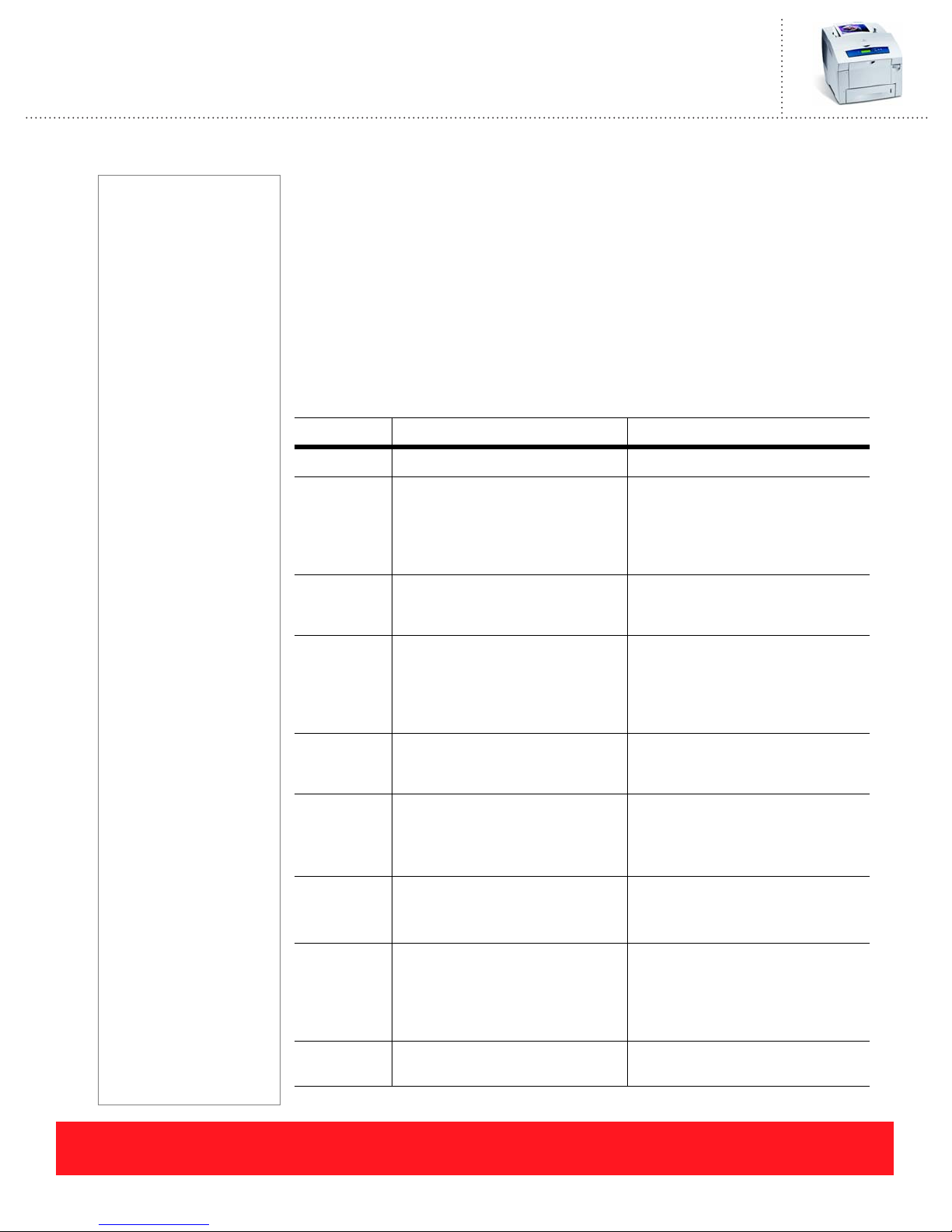
Phaser 8550, 8500, & 8400 Service Self-Study Guide
SERVICE SECTION
Prerequisites
❑ Service section of the
Phaser 8550, 8500, &
8400 Product Training
CD-ROM
Time To Complete
❑ Reading: 40 min.
❑ Video run time: 90 min.
❑ Exercises: 45 min.
❑ Optional labs: 3 hours
Equipment Checklist
❑ Phaser
8400/8500/8550
Service Manual
❑ Access to the Internet
and Xerox knowledge
base web site
❑ Phaser 8400, 8500, or
8550 printer (optional)
❑ Tools for disassembly
(optional)
References
Electronic copies of all
manuals, guides, and
instruction sheets are
located on the training
CD-ROM.
Use the training CD-ROM's
Resources section to
access the manuals and
other documentation.
Service Objectives
■ Perform service troubleshooting procedures
■ Recognize printer-specific precautions
■ Understand tips for replacing service parts
This section of the Self-Study Guide contains information about troubleshooting
the printers as well as printer-specific precautions and parts replacement tips. To
begin, if you are familiar with the previous generation Phaser 800-series printers,
use the chart below to identify the Phaser 8400, 8500, and 8550 differences.
System Phaser 8400/8500/8550 Phaser 840/850/860/8200
Printhead
Printhead
Maintenance
Electronics
Process
Drive
Media Path
Drum
1236 jet-nozzles/309 jets per color 448 jet-nozzles/112 jets per color
Purge Pump blows air into
Printhead, generating pressure to
purge ink out the faceplate
Wiper Assembly cleans the
Printhead faceplate
Electronics Module contains Main
Board, Power Control Board, and
Vacuum/Pump Module generates
vacuum that sucks ink out of
faceplate
Cap/Wipe/Purge Assembly holds
vacuum and cleans the faceplate
Separate Main Board, Power
Control Board, and Power Supply
Power Suppl y
Located on right printer frame
Pivoting gear switches between
Transfix and Drum Maintenance
Camshafts
Located on left printer frame
Belts, clutches, and missing tooth
gears are used to engage the Paper
Pick, Drum Maintenance, Printhead
Tilt, and Transfix systems
Media Drive assembly contains
Paper Feed Motor, clutches, and
Individual Paper Feed Motor,
clutches, and drive gear trains
gears
Large diameter Drum allows for full
legal-size image
Built-in drum encoder and heater
Small Drum limits image size on
legal-size pages
Individual Drum Encoder and Drum
Heater assemblies
Y-axis Drive
Drum
Maintenance
Transfix
PHASER 8550, 8500, & 8400 SERVICE SECTION
Version 1.0
Located on left printer frame
Floating tension system maintains
Located on right printer frame
Belt tension adjustment is critical
constant tension on drive belt
Maintenance Kit is self-contained
Pivot plate rotates the
Maintenance Kit into position
during maintenance cycle
Individual roller, counter, and Drum
Maintenance Drawer
Lift pins on drum Drum
Maintenance Drawer position roller
and blade during maintenance cycle
Roller can be individually replaced Drum/Transfix Assembly includes
roller
page 67
Page 76

Troubleshooting
This lesson describes the service tools available for troubleshooting the printer. It also presents
information for troubleshooting specific types of product failures including error codes,
print-quality problems, electronics, and printhead issues.
Service Tools
The Phaser 8400/8500/8550 Color Printer Service Manual is the primary service tool for the printer. It
contains the service information for all three printer models including troubleshooting procedures and parts
replacement instructions. Always follow the procedures in the manual closely in order to successfully
troubleshoot failures and replace service parts. In addition to the Service Manual, use the following tools
when servicing the printer:
■ Torque screwdriver - Xerox part number 003082700
■ T-20 screwdriver tip - Xerox part number 003086600
■ Grease - Xerox part number 006799700
■ Service Diagnostics mode
■ Xerox knowledge base
■ Service Flashes and Service Bulletins
Error Codes
The printers report error codes using the Control Panel display, the status LED, and the PS & PE LEDs
located just above the Power Switch. Troubleshooting procedures for each error code are provided in the
Error Message and Codes section of the Service Manual. This topic describes how to recognize and
troubleshoot BIST/POST codes, PEST errors, jam codes, and print engine fault codes.
BIST and POST Errors
Immediately after the Power Switch is turned on, the printer performs Built-In Self Tests (BIST) followed by
Power On Self Tests (POST). BIST errors are reported by blinking a code on the PS and PE LEDs because
the tests occur before the Control Panel is initialized. POST testing occurs after Control Panel initialization,
so errors can be reported on the Control Panel display. POST errors are also reported by blinking the printer’s
LEDs, while non-critical errors are reported on the Startup Page. Troubleshooting procedures for each BIST
and POST error are located in the Error Messages and Codes section of the Service Manual.
See “Resources” on page 94 for additional sources of service information.
page 68
PHASER 8550, 8500, & 8400 SERVICE SECTION
Version 1.0
Page 77

Error Type Error Reporting Service Manual Topics
BIST Blinks the PS & PE LEDs just above the Power Switch BIST Rear Panel LED
Codes Table
POST Error code is displayed on the Control Panel POST (Power On Self
Blinks the Control Panel status LED (for codes greater than 5, a short
pause occurs between each group of five blinks)
Blinks the PS & PE LEDs just above the Power Switch (for codes
greater than 5, a short pause occurs between each group of five blinks)
Prints a message on the Startup Page for non-critical errors only
BIST and POST failures are generally related to the electronics module.
Test) Error Messages
Ta bl e
PEST Errors
Print Engine Self Tests (PEST) occur during the printer’s mechanical initialization sequence. The tests
identify disconnected wiring harnesses, shorted motors, and power supplies that are out of tolerance. PEST
failures are reported on the Control Panel using a 37,000-series error code. The codes are stored in the
printer’s Engine Error History and are included on the embedded Printer Status Page and Usage Profile
Report.
The Wiring Diagrams section of the Service Manual provides a visual key that relates each 37,000-series
PEST error code to the corresponding wiring harness. Detailed troubleshooting procedures are located in the
Service Manual’s Fault Code Error Message Troubleshooting section.
Error Type Error Reporting Service Manual Topics
PEST 37,000-series error code on Control Panel display Wiring Diagrams section
Stored in Print Engine History (Service menu)
Included on the embedded Printer Status Page and Usage
Profile Report pages
Use the Wiring Diagrams section of the Service Manual to solve PEST errors
that are reported after you replace printer parts.
PHASER 8550, 8500, & 8400 SERVICE SECTION
Version 1.0
(disconnected wiring harnesses)
Fault Code Error Messages
Troubleshooting section
page 69
Page 78

Jam Codes
Jam codes are stored in the printer’s Jam History each time paper jams occur. Each Phaser 8400 jam code
contains a group of three digits while Phaser 8500 and 8550 jam codes contain four digits. The jam codes
identify the information indicated below.
■ Print process that was active when the jam
occurred
■ The reason or basis for reporting the jam
■ Page count when the jam occurred
■ Tray from which jammed paper was picked
(1 - 4) or when processing chase or duplex
pages (Phaser 8500 and 8550 only)
■ Printer state when the jam occurred
Phaser 8400
Jam Code
Print Process Event
Reason for Jam
Phaser 8500/8550
Jam Code
Print Process Event
Reason for Jam
20:A2C:773
Page Count
Printer State
20:F2N2:773
Page Count
Tray/Chase/Duplex
Printer State
Tables located in the Jam Codes section of the Service Manual define the jam code digits and provide
troubleshooting procedures for specific codes.
Error Type Error Reporting Service Manual Topics
Jam Code Codes are stored in Jam History (Service menu) Jam Code Key Table (code
definitions)
Codes are included on the embedded Printer Status Page
and Usage Profile Report
Jam Code Troubleshooting
Procedures
page 70
When Phaser 8500 and 8550 printers are in a jam condition, press the Help
button to quickly view the jam code.
Print Engine Fault Codes
Print engine faults can occur during the power-on sequence or during printer operation. Many faults can be
cleared by cycling the printer’s power switch. When a fault occurs, the printer automatically resets in an
attempt to clear the error. The printer reboots, beginning with the BIST and POST tests, and attempts to
complete the power-on sequence. If the fault persists after the automatic reboot sequence, the print engine
fault code appears on the display. This code is stored in the printer’s Engine Error History and is included on
the embedded Printer Status Page and Usage Profile Report.
Each print engine fault code contains four fields as
shown to the right. The fields define the failing printer
7,009.42:836
system, subsystem, problem type, and page count
when the error occurred. The Service Manual’s Fault
Failing System
Page Count
Code Error Message Troubleshooting section provides
troubleshooting procedures for each code.
Failing Subsystem
PHASER 8550, 8500, & 8400 SERVICE SECTION
Type of Problem
Version 1.0
Page 79

Error Type Error Reporting Service Manual Topics
Print Engine
Fault Code
Search the knowledge base and check for Service Bulletins or Flashes to
locate new troubleshooting information on specific fault and error codes.
Fault code is displayed on the Control Panel Fault Code Error Message
Troubleshooting
Stored in the Print Engine History (Service menu)
Included on the embedded Printer Status Page and Usage
Profile Report pages
Error Codes Review Exercise
Use your Phaser 8400/8500/8550 Service Manual to locate troubleshooting information for the
error codes below. An electronic version of the manual is available in the training CD-ROM’s
Resources section.
The answers for this exercise are located in the Appendix on page 92.
1. Locate and record the two most likely failures when the Control Panel displays the message
“POST Failure 11.02: ___________________________________________________________
2. After replacing the Media Drive Assembly, the printer reports error code “37,015.40”. Use the
Service Manual to determine which wiring harness is disconnected. ______________________
_____________________________________________________________________________
3. A Phaser 8400 printer is jamming on every page. The Jam History shows several instances of the
“B3T” jam code. Use the Service Manual to determine which sensor is responsible for this error.
_____________________________________________________________________________
Print Quality
Most print-quality problems can be resolved by the end user. The most common print-quality defects are
caused by one of the following:
■ Unsupported or damaged media
■ Software applications and driver settings
■ Areas in the printer that require cleaning
■ Non-Xerox or expired supplies (ink sticks and maintenance kits)
The Print-Quality Troubleshooting section of the Service Manual contains instructions for diagnosing
print-quality problems. It describes the built-in Service Test Prints that are provided for evaluating specific
print-quality issues. Also provided are symptom-based troubleshooting procedures, which include
step-by-step procedures for repairing the printer.
PHASER 8550, 8500, & 8400 SERVICE SECTION
Version 1.0
page 71
Page 80
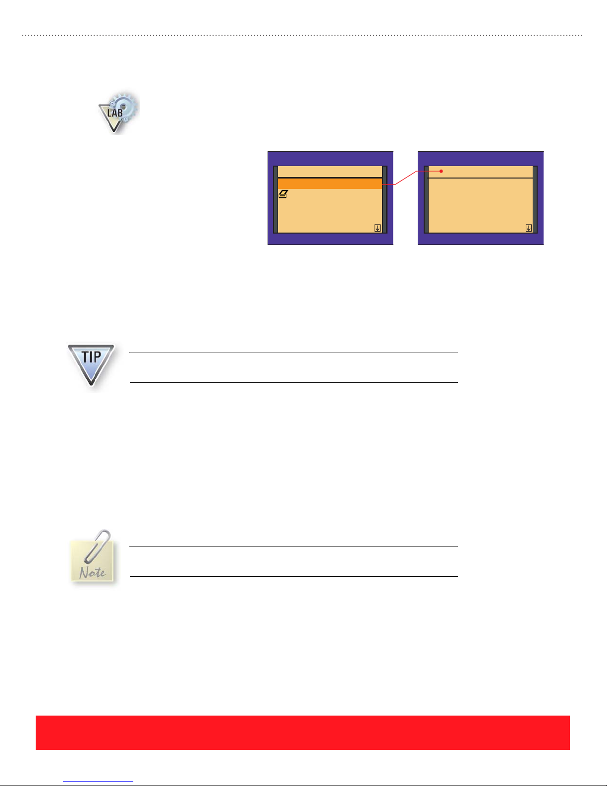
Service Test Prints Lab
The Service Test Prints can be accessed using the hidden Service menu. To display the menu, a
special combination of Control Panel button presses is required. If a printer is available, use the
following procedure to access the Service Test Prints from “Ready To Print”, and then print the
pages indicated for reference when troubleshooting print-quality problems.
1. Scroll to Troubleshooting and
press OK.
2. Scroll to Service Tools and
press OK.
3. Press and hold the UP arrow
button, and then press the
Ph ase r 8400 Ph ase r 8400
Test Prints
Startup Page
Eliminate Light Stripes
Fault History
Jam History...
DOWN arrow button to
display the Service menu.
4. Press OK to enter the Test Prints menu.
5. Print the following Service Test Prints:
■ Weak/Missing Jets
■ Solid Fill prints of each primary color (CMYK)
Service
Test Prints
1: Weak/Missing Jets
2: X-axis Motion
3: Color Bands, RGBK Dithers
4: Reverse Text
5: Big Hand feed OHP
The Service Test Prints available on Phaser 8400 printers are not the same as
those available for Phaser 8500 and 8550 printers.
Symptom-Based Troubleshooting Procedures
The symptom-based troubleshooting procedures provide a visual example of each print-quality problem
followed by the troubleshooting procedure. In general, the procedures assume that you have printed an
embedded page to isolate the problem to the printer. Problems that appear on embedded pages, such as the
Light Stripes Test Page, cannot be caused by the customer’s computer, network, or software application.
Each procedure begins with the user-level solutions that apply. Service parts should be replaced only after
attempting to solve the problem by replacing the specified supply items or performing cleaning procedures.
To avoid replacing expensive service parts, always follow the troubleshooting
steps in the specified order.
page 72
PHASER 8550, 8500, & 8400 SERVICE SECTION
Version 1.0
Page 81
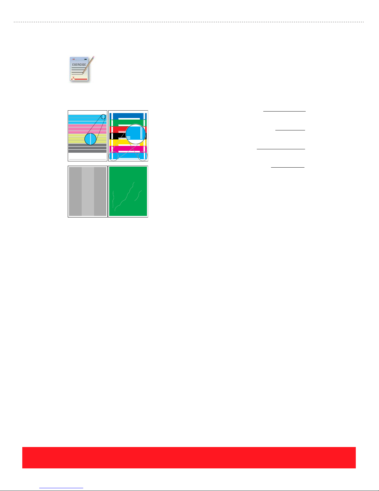
Print Quality Review Exercise
1234567890
747576 77787980
Use the Analyzing Service Test Prints section of your Service Manual to match the following
print-quality problems with the most likely cause. Pay special attention to the paragraphs
entitled “Look For” and “Causes”, which explain how to evaluate the print and diagnose the
printer when the print shows defects.
The answers for this exercise are located in the Appendix on page 92.
Missing Jet Thin Line Missing
10 point Times-Roman ABCDEFGHIJKLMNOPQRSTUVWXYZabcdefghijklmnopqrstuvwxyz1234567890
8 point Times-Roman ABCDEFGHIJKLMNOPQRSTUVWXYZabcdefghijklmnopqrstuvwxyz1234567890!@#$%^&*
6 point Times-Roman ABCDEFGHIJKLMNOPQRSTUVWXYZabcdefghijklmnopqrstuvwxyz1234567890!@#$%^&*
5 point Times-Roman ABCDEFGHIJKLMNOPQRSTUVWXYZabcdefghijklmnopqrstuvwxyz1234567890!@#$%^&*
4 point Times-Roman ABCDEFGHIJKLMNOPQRSTUVWXYZabcdefghijklmnopqrstuvwxyz1234567890!@#$%^&*
Light Band Wrinkling
Electronics Troubleshooting
The Electronics Troubleshooting section of the Service Manual provides step-by-step instructions for
diagnosing problems with the power supplies and other printer electronics. Use this section of the Service
Manual to isolate problems when the printer cannot display an error code. Use the following tips when
troubleshooting the printer electronics.
Electronics Module
1. Stuck Preheater Plate
2. Defective Printhead Wiper
3. Unsupported Media
4. Dirty Drum Temperature
Sensor
The Electronics Module is expensive. Replace it only when specified by the troubleshooting procedures.
Refer to the Service Manual for procedures to test the Electronics Module by disconnecting it from other
printer components.
Erratic or Intermittent Failures
Erratic or intermittent printer failures can occur if the grounding clips are damaged or improperly installed, or
if wiring harnesses are improperly dressed. Refer to the Wiring Diagrams section of the Service Manual for
examples of proper wiring. Use the Service Manual’s Ensuring Ground Integrity section to locate the
grounding connections.
Measuring Power Supply Voltages
The printer measures its internal power supplies during the PEST tests. If all PEST tests pass, the power
supply voltages are within tolerance. Service Diagnostics provide an alternate way to measure the power
supplies. Refer to the procedure on the next page.
PHASER 8550, 8500, & 8400 SERVICE SECTION
Version 1.0
page 73
Page 82

1. Enter the Service Diagnostics mode. If necessary, refer to the Service Diagnostics section of the
Service Manual for instructions.
2. Select the Check Menu.
3. Select the Misc Menu.
4. Select “Voltages” from the menu.
5. Refer to the Service Manual’s Check Misc Menu table to verify the results for each power supply.
The power supply is referenced to +3.3 Volts. If the +3.3 Volt reference has
failed, all the DC supplies will be out of tolerance.
Shorted Heaters
Shorted heaters will cause fuses F2 or F3 to open (see schematic on page 75). Both fuses are located on the
Power Supply Board within the Electronics Module. Before replacing the module, refer to the Service
Manual topic Detecting condition of F2 and F3 to test the fuses.
If the printer contains a shorted heater, the heater must be replaced along
with the Electronics Module. Otherwise, the shorted heater could cause the
replacement Electronics Module to fail.
Printhead Troubleshooting Checklist Exercise
The On-Site Printhead Troubleshooting Checklist provides procedures for accurately diagnosing
print-quality problems. Checklists are located in the Appendix section of the Service Manual, on
the Xerox support website, and inside the box of replacement Printheads. Use the Phaser 8500
and 8550 On-Site Printhead Troubleshooting Checklist to answer the following questions.
The answers for this exercise are located in the Appendix on page 92.
1. What information are you checking for in Step 1 of the checklist? ________________________
2. If the printer has error code 13,197.4x, name two troubleshooting steps to complete before
replacing the Printhead: _________________________________________________________
_____________________________________________________________________________
3. Which part, when defective, will cause streaks or smudges of ink on the Printhead faceplate?
_____________________________________________________________________________
4. If the Printhead has weak or missing jets, how many times should you run Eliminate Light Stripes
using the Control Panel? _________________________________________________________
5. Under what conditions should the Printhead be replaced instead of using Jet Substitution mode?
_____________________________________________________________________________
Printhead troubleshooting procedures are updated periodically. The most
up-to-date checklist is available on the Xerox web site and is packaged with
replacement Printheads.
page 74
PHASER 8550, 8500, & 8400 SERVICE SECTION
Version 1.0
Page 83
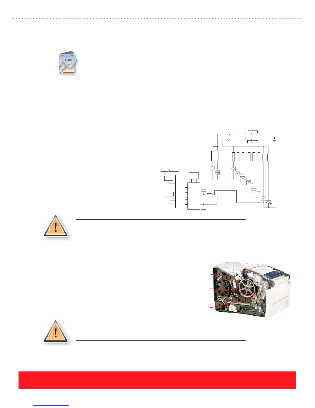
Service Precautions
This lesson describes important precautions to observe when servicing the printer. These include
potential safety hazards on the printer, ways to avoid damaging the customer’s environment, how
to properly handle service parts, important information about grounding connections, and how to
home components to avoid possible damage during the power-on sequence.
Hazards
The Service Manual’s Service Safety Summary describes general service precautions that you should read
before servicing this printer. In addition to those listed in the Service Safety Summary, service technicians
should be aware of potential hazards with AC voltage and the Y-axis drive system.
AC Voltage
AC heaters are used in the Printhead, Ink
Loader, Drum, and Preheater Assemblies
as shown to the right. Whenever the AC
power cord is connected to the printer,
lethal AC line voltage may be present at
any of these assemblies. The printer’s
Power Switch does not physically
disconnect the AC line from internal
components. Disconnecting the power
cord is the only way to isolate the printer
components from the AC line.
AC Line
Low
Switcher
AC Neutral
+3.3 V
+15 V
-15 V
+50 V
-50 V
F3
F2
P
D
r
r
e
u
h
m
t
H
8
Serial
Control
Interface
H13
H12
H11
H10
H9
H8
H4
H3
H2
H1
uProcessor
Vcc
REG
Vss
I
n
k
4
H
9
AC Line
S1
AC Neutral
I
I
I
n
n
n
k
k
k
3
2
1
H
1
3
H
1
2
H
1
1
Line
Gnd Ref
Neutral
r
r
e
e
jsrjs
s
s
I
2
1
H
1
0
H
4
H
3
H
2
H
1
To avoid serious injury, always turn the printer off and unplug the power cord
before replacing components.
Y-Axis Drive System
The Y-Axis Drive uses a closed-loop servo system to
maintain a constant rate of Drum rotation. This system
monitors the Drum and increases drive current to
compensate for decreases in Drum speed, which will
occur when thicker media is used. When servicing the
printer, always keep your fingers, clothing, and tools
away from the drum pulley and belt.
To avoid serious injury, always keep fingers, clothing, and tools away from the
Y-Axis Drive System.
Drum Pulley
Drum Belt
Y-Axis Motor
PHASER 8550, 8500, & 8400 SERVICE SECTION
Version 1.0
page 75
Page 84
Customer Environment
Technicians must always be careful to protect the customer’s office environment, including the furniture and
carpets. When servicing these printers, the most likely ways to cause damage are scratches caused by sharp
edges and spilling liquid ink.
To protect the customer’s office furniture, use a cloth to cover your work area.
Handle the Printhead and Ink Loader Assemblies carefully to avoid ink spills.
Scratches
Sharp edges on tools and printer components can scratch finished surfaces such as table tops and desks.
Damage can occur when components such as the Electronics Module, Printhead, Preheater, and grounding
clips are removed and placed directly onto furniture. If the printer is located on a finished surface, rotating it
can also cause scratches. To protect the customer’s office furniture, use a cloth to cover the work area.
Ink Spills
The Printhead and Ink Loader Assemblies contain liquid ink. To avoid ink spills, allow the printer to cool for
30 minutes before removing components. This allows the liquid ink to solidify. If you must remove the
Printhead and Ink Loader Assemblies while they are still warm, observe the following precautions:
■ Never place the assemblies directly onto carpeting, upholstery, or finished surfaces.
■ Place the assemblies on several sheets of paper and ensure they cannot be tipped over.
■ Never place the Printhead on its side (keep the reservoirs facing up).
■ Use a cloth to cover your work area.
Handling Parts
Printer parts can be damaged by mishandling them. This topic provides a review of the Electro-Static
Discharge (ESD) precautions and lists the components that can be physically damaged by improper handling.
Damage from ESD
Many of the printer assemblies are susceptible to ESD. When handling parts, always observe the proper
precautions for ESD, which include the following:
■ Use a static dissipative mat, wristband, and grounding cord with clips.
■ Use proper packaging for static sensitive components.
■ Keep replacement parts in their packaging until you are ready to install them.
Failure to protect parts from ESD can cause damage that leads to repeat
service calls.
page 76
PHASER 8550, 8500, & 8400 SERVICE SECTION
Version 1.0
Page 85
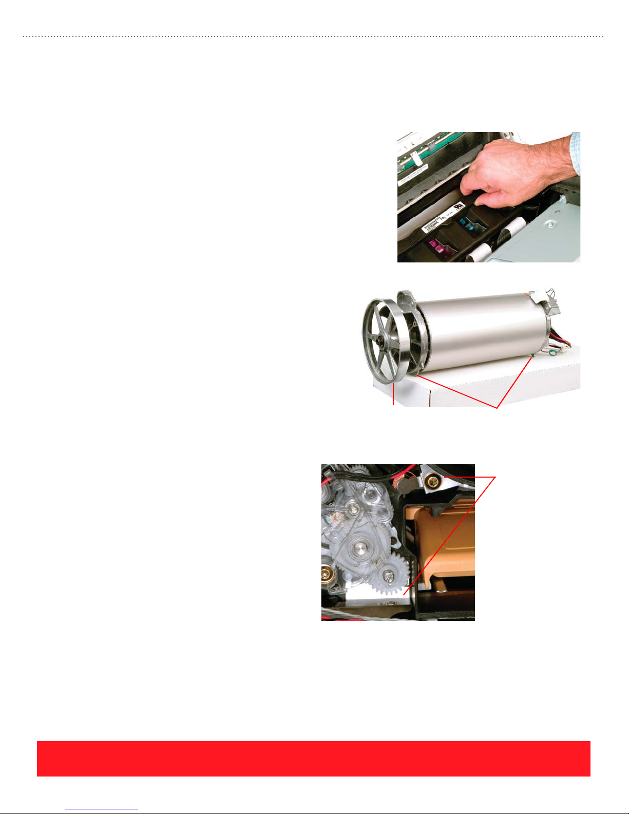
Physical Damage
Technicians should always handle printer components carefully to avoid damage. Handle the following parts
carefully to avoid damage when servicing the printer:
■ Transfix Roller - Avoid dropping the Transfix
Roller. Dents in the rubber roller will cause
repeating print defects at 11.6 cm (4.58 in)
intervals.
■ Printhead - When handling the Printhead, never
touch the faceplate area with your hands or tools
to avoid scratches. If the Printhead is hot, hold it
using the rounded lift points to avoid burns, as
shown to the right. Finally, never position the
Printhead on its faceplate to avoid damage to the
faceplate and ink spills.
■ Drum Assembly - Handle the Drum
Assembly carefully to avoid dents or
scratches. Any defect on the Drum also
appears in the printed image. To protect the
Drum Assembly after removal, place it on its
feet while extending the pulley over the edge
of the work surface as shown to the right.
Grounding
Drum Assembly FeetPulley
The Phaser 8400, 8500, and 8550
printer frame is constructed from
molded plastic. Each component that is
mounted onto the plastic frame returns
to ground through the Electronics
Module. This ground connection is
especially important for rollers and
motors, which generate static charges as
they rotate. To provide grounding paths
for each component, the printer uses a
series of metal grounding clips and
cables.
Erratic or intermittent printer failures can occur if the grounding clips and cables are damaged or improperly
installed. Symptoms include erratic Control Panel behavior and intermittent printer resets or hangs. If the
grounding clips and cables are not installed, static charges build and then discharge, causing damage to the
printer electronics.
Examples of
Grounding Clips
PHASER 8550, 8500, & 8400 SERVICE SECTION
Version 1.0
page 77
Page 86
Homing Components
After servicing the printer, it is important to manually set four components to their home position in order to
avoid errors or grinding gears during the power-on sequence. Before powering on the printer, verify the
following components are set to home:
Assembly Home Position Home Indicator Setting To Home
Printhead
Wiper
Assembly
Printhead
Titl Gear
Printhead Printhead tilted
Process
Motor
Assembly
Wiper Assembly at
bottom of travel.
Tilt gear disengaged
from drive gear train.
forward against Drum
(print position).
Tilt Gear disengaged
from drive gear train.
Transfix Camshaft,
Drum Maintenance
Camshaft, and two
large gears within
Process Drive
Assembly line up with
home indicators.
When the Wiper Assembly is in the
home position, you can remove the
Waste Tray. When the Wiper
Assembly is raised up from home
position, it locks the Waste Tray
into the printer.
When the Tilt Gear is disengaged,
the two arrows on the left printer
frame point at each other.
When the Tilt Gear is disengaged,
the two arrows on the left printer
frame point at each other.
A dot on the Transfix Camshaft
lines up with a dot on the printer
frame.
A dot on the Drum Maintenance
Camshaft lines up with an arrow on
the ground plane.
Two holes through the Process
Drive Assembly housing line up
with holes through the two large
gears.
If necessary, unlock the Wiper Assembly Lock.
Rotate the wiper drive gears to move the
assembly downward.
If the Printhead is removed, reach inside the
frame and rotate the gear.
If the Printhead is installed, remove the
Maintenance Kit. Then, use a screwdriver to
rotate the Drum Maintenance Camshaft one
revolution CW. You will hear a clicking sound
when the Tilt Gear disengages the drive train.
Disengage the Tilt Gear from its drive train.
Move the Printhead Wiper Assembly to the
bottom of its travel.
Carefully guide the Printhead forward. You may
need to move the Printhead horizontally before
tilting it forward.
Remove the Process Drive Assembly.
Verify the Transfix Camshaft and Drum
Maintenance Camshaft align properly with the
homing marks.
Before installing the Process Drive Assembly,
verify the two large gears align with the holes
through the assembly housing. Pin them in
place and then reinstall the assembly.
To avoid errors and grinding noises when powering on the printer, always
home the Printhead Wiper Assembly, Printhead Tilt Gear, Printhead, and
Process Motor Assembly before turning on the Power Switch.
page 78
PHASER 8550, 8500, & 8400 SERVICE SECTION
Version 1.0
Page 87
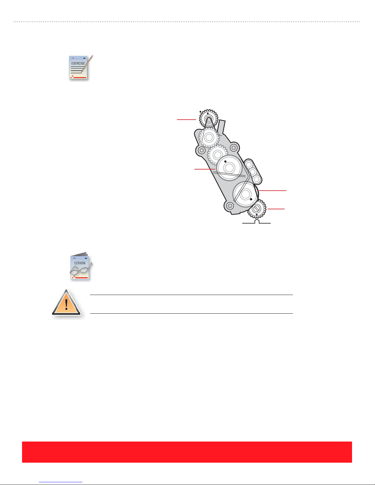
Homing Components Review Exercise
Read the Printer Component Homing Positions and Indicators topic in the Service Manual to
become familiar with procedures for homing components. Use the Homing the Process Gear
Drive Train section of your Service Manual to determine which gears (1 - 4) are home in the
diagram below.
The answers for this exercise are located in the Appendix on page 93.
1. Home / Not Home
1
2. Home / Not Home
3. Home / Not Home
4. Home / Not Home
2
3
4
Parts Replacement Tips
This lesson provides hints and tips that will help you avoid problems when replacing service
parts, including the exterior covers as well as assemblies within the printer. Always refer to the
Service Parts Disassembly section of the Service Manual when replacing printer parts.
Carefully following the manual’s step-by-step instructions will help you to
avoid damaging printer parts.
Exterior Covers
Use the following information when removing the Control Panel cover, left and right side covers, and the
exit cover.
PHASER 8550, 8500, & 8400 SERVICE SECTION
Version 1.0
page 79
Page 88
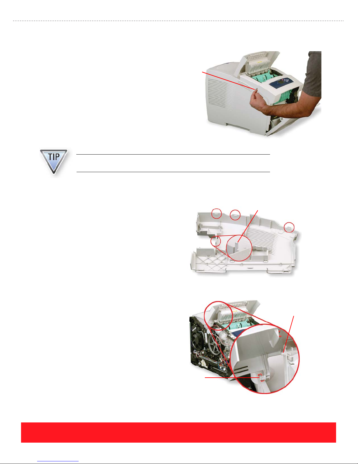
Control Panel Cover
Use your fingers or a small screwdriver
to pry up on the left side of the cover as
shown to the right, and then pull it
forward. After the cover is loose, press
down on the Control Panel to release it
from the cover.
Keep the Control Panel attached so the printer will function after removing the
Control Panel cover.
Left & Right Side Covers
Each side cover has latches along the
top edge in the locations shown to the
right. Release them by pulling up on the
rounded area near the back of the
printer and near the front cover.
Pry Here To
Remove Cover
Right Side Cover Only
The right side cover has one more latch
located next to the power cord
receptacle. You may need to release this
latch when removing the cover.
Exit Cover
Mounting pins located on each side of
the exit cover are captured by the left
and right side covers. Be sure to install
the exit cover and position the pins into
notches on the Ink Loader Assembly
frame before installing the side covers.
Also, make sure posts on each side of
the exit door slide freely within the
groove on the bottom of the exit cover.
Post On
Exit Door
Mounting Pin
page 80
PHASER 8550, 8500, & 8400 SERVICE SECTION
Version 1.0
Page 89
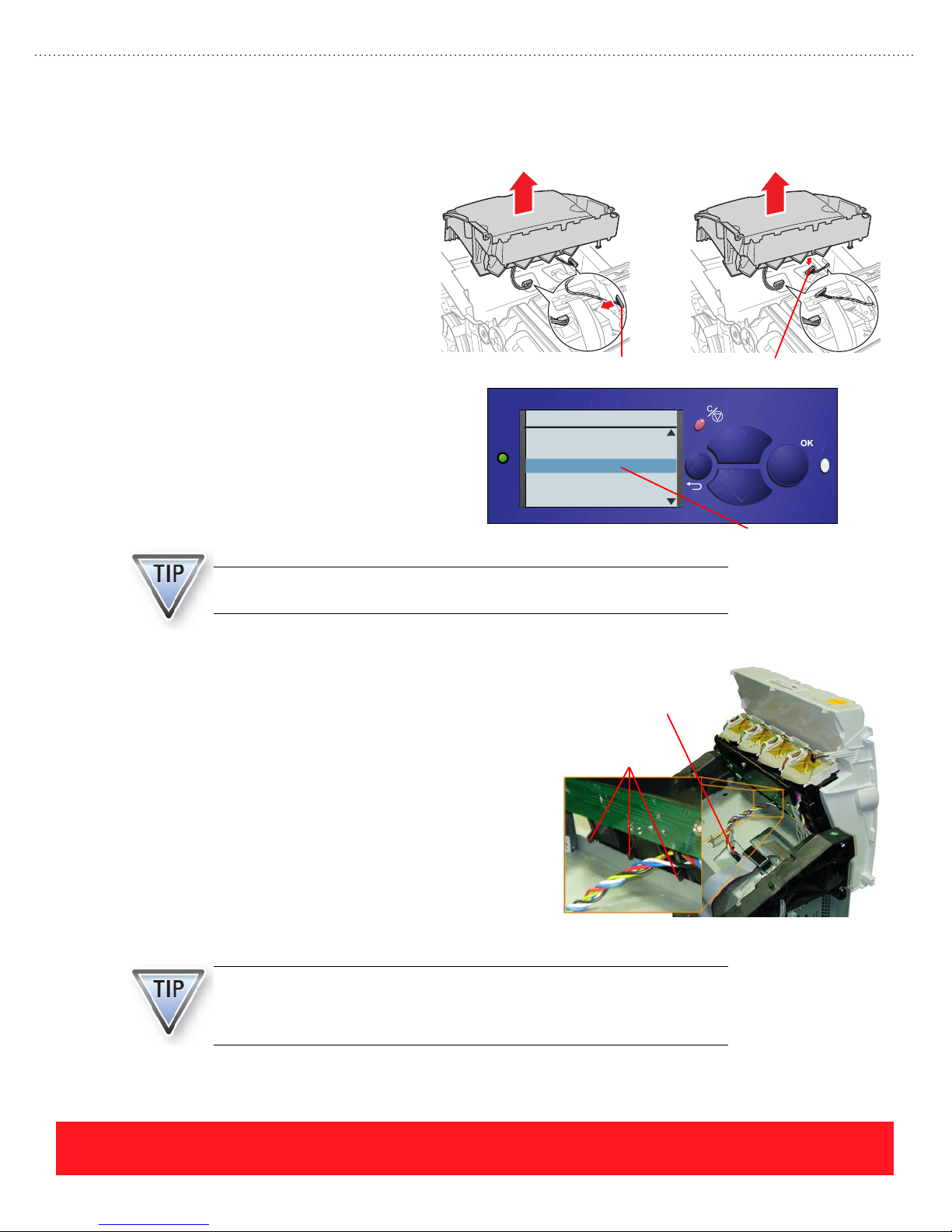
Ink Loader Assembly
The procedure for replacing the Ink
Loader Assembly is slightly different for
Phaser 8400 Phaser 8500/8550
Phaser 8400 and Phaser 8500/8550
printers. On Phaser 8400 printers,
disconnect the Ink Loader data cable at
the printer frame. On Phaser 8500/8550
printers, disconnect the cable at the Ink
Loader Assembly, as shown to the right.
Disconnect From Frame Disconnect From Ink Loader
After replacing the Ink Loader Assembly
on Phaser 8500 and 8550 printers, use
the Control Panel’s hidden Service menu
to reset the Ink Loader. This allows the
printer to accurately count the number of
ink sticks used.
An error code will be displayed if you replace the Phaser 8500 or 8550 Ink
Loader Assembly without resetting the ink stick count.
Phaser 8550
Service
Wipe Adjust
Purge Adjust
Reset Ink Loader
Service Usage Profile
Print OCR Usage Profile
6350DT
?
Reset Ink Loader
The Phaser 8400, 8500, and 8550 Ink Loader
Assemblies are designed to hang off the rear of the
printer to expedite troubleshooting. For example, you
may need to watch the Printhead or Wiper Assembly to
visually determine the cause of failure. Hang the Ink
Loader Assembly by attaching its plastic hooks over
the Electronics Module as shown to the right.
Tilting the Printhead back can uncover an ink level
sensor inside the Printhead and trigger an ink melting
cycle. If the printer melts ink, it flows down into the
Ink Loader Assembly and can damage the “ink out”
sensors. If a sensor has been damaged, the printer will
display a 9,03x.xx error several hours or days later,
after 2.5 inks sticks of a color have been melted.
To prevent ink from melting into the Ink Loader Assembly, never print with
the Ink Loader Assembly attached to the rear of the printer.
To disable the ink melt units, unplug the AC heater cable shown above.
Unplug AC Heater Cable
To Disable Ink Melt Units
Plastic Hooks
PHASER 8550, 8500, & 8400 SERVICE SECTION
Version 1.0
page 81
Page 90
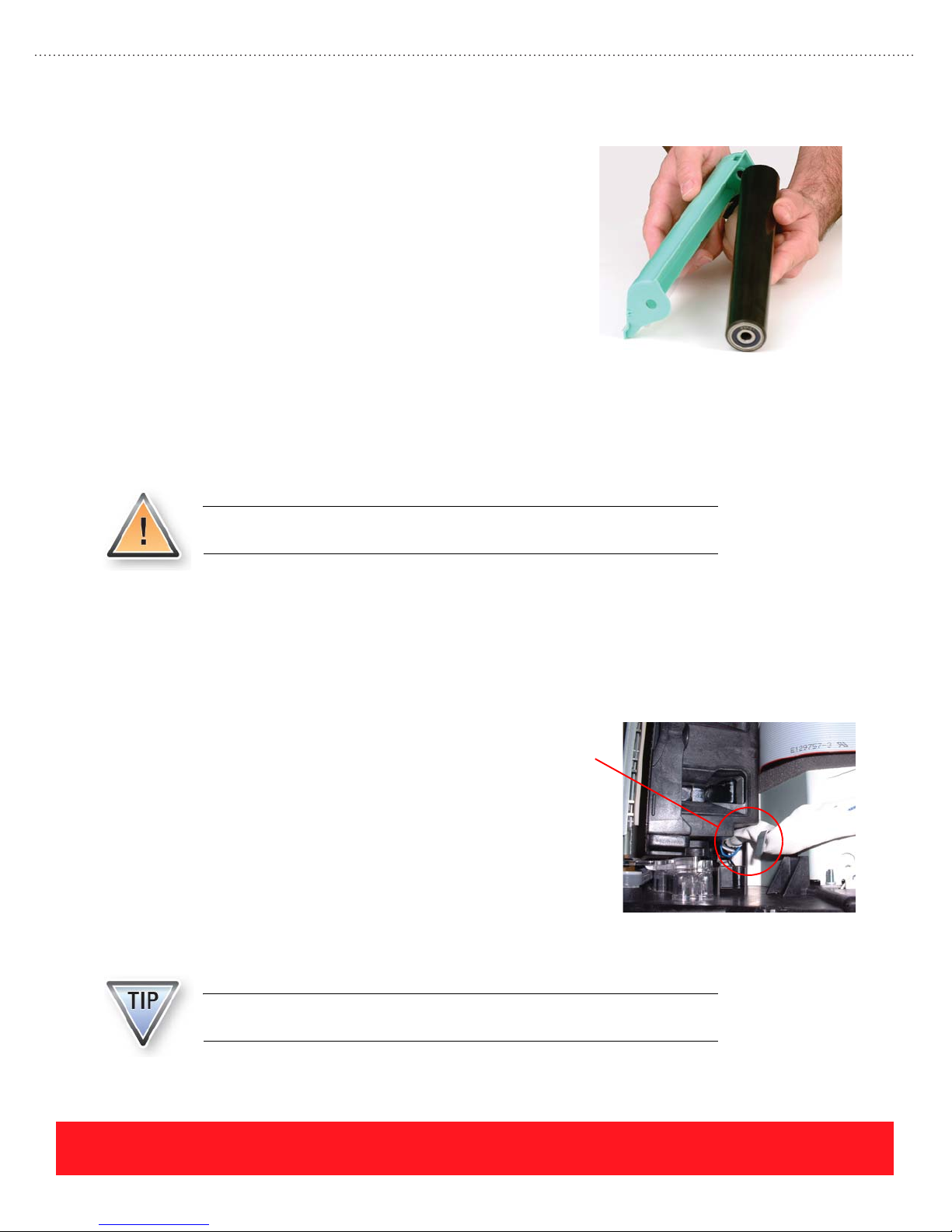
Stripper Carriage Assembly
When removing the Stripper Carriage Assembly, be sure to
hold the Transfix Roller firmly when lifting the assembly out
of the printer. After removing the Transfix Roller Shaft to
free the assembly from the printer frame, the Transfix Roller
will drop out of the Stripper Carriage Assembly as shown to
the right. Dropping the roller can damage it and cause
repeating print-quality defects.
Printhead
Closely follow the Service Manual procedures when replacing the Printhead. Skipping steps can result in
damage. This topic provides general Printhead replacement tips and highlights differences between the
procedures for Phaser 8400 and Phaser 8500/8550 printers.
To avoid damage, closely follow the Service Manual’s Printhead replacement
procedures.
General Printhead Replacement Tips
Use the following tips when replacing the Printhead:
■ Follow the On-site Printhead Troubleshooting Checklist to accurately diagnose the problem.
■ Use the lift points on top of the Printhead to avoid burns and contact with the faceplate.
■ Carefully dress the AC power cable so it does not
interfere with Printhead motion. In the example to
the right, the cable is pinched by the Printhead,
Pinched
Cable
which can cause 4,025.xx and 7,009.xx error codes.
■ Carefully handle the Roll Block, which remains
hot for several minutes after power is turned off.
■ Before removing the Printhead, unbox the
replacement Printhead. Place the old Printhead in
the empty box to prevent burns and ink spills.
■ After Printhead replacement, verify that Service Mode (jet substitution) is turned off by printing
the Light Stripes Page or Printer Status Page.
Print-quality issues and other performance problems will occur if Service
Mode remains enabled after Printhead replacement.
page 82
PHASER 8550, 8500, & 8400 SERVICE SECTION
Version 1.0
Page 91
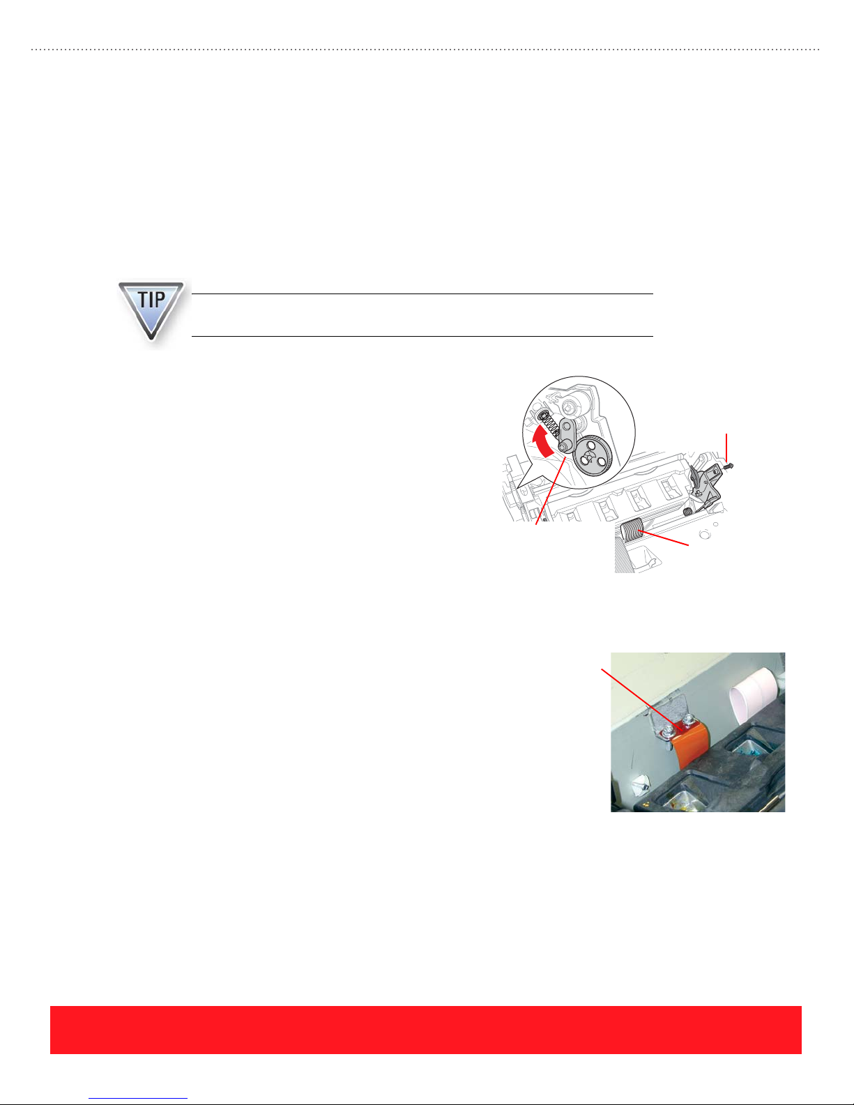
Procedure Differences
An important difference between Phaser 8500/8550 and Phaser 8400 printers involves an identification code
that is stored in all Phaser 8500/8550 Printheads and Electronics Modules. When installed in a printer, the
codes for each assembly must match. If the codes fail to match, the printer reports an error.
The code for replacement Phaser 8500/8550 Printheads and Electronics Modules is set to zero at the factory.
After a replacement assembly has been installed, the printer updates the new assembly to match the other
assembly in the printer. If a Printhead or Electronics Module is used for troubleshooting, it must be returned
to the factory to reset its code.
Phaser 8500/8550 printers display error 19,004.40 if the Printhead and
Electronics Module codes do not match.
Technicians should also be aware of the following
differences between the Phaser 8400 and Phaser
8500/8550 Printhead replacement procedures:
Tighten Screws
To 6 Inch-Pounds
■ The Wiper Lock Assembly in
Phaser 8500/8550 printers has been
redesigned to improve reliability, but the
method used to unlock it is the same as for
Phaser 8400 printers. Press up on the
plastic arm as shown to the right.
■ Phaser 8500/8550 printers have one ZIF
cable while Phaser 8400 printers have two.
Wiper Lock Assembly
(Press Up To Unlock)
One ZIF Cable
■ To avoid stripping the Printhead Restraint
screws, tighten them to 6 in-lbs.
■ A ground strap is located behind the Printhead on
Phaser 8500/8550 printers to improve EMI
performance. When removing the Printhead,
disconnect the ground strap by removing the two
screws shown to the right.
Ground Strap
PHASER 8550, 8500, & 8400 SERVICE SECTION
Version 1.0
page 83
Page 92

Electronics Module
A small piece of tape is included with
each Phaser 8500/8550 replacement
Electronics Module. After installing the
replacement assembly, use the tape to
seal the top side of the housing where
the Printhead Data Cable passes through
it, as shown to the right. The tape
ensures the assembly meets EMI
specifications.
X-Axis Motor Assembly
Use the following tips when replacing the X-Axis
Motor Assembly:
Apply Tape
Here
■ Slide the notch on the Nose Cone Gear over
the rail extension on the printer frame. The
rail stabilizes the Nose Cone Gear so the
X-Axis Shaft can thread in and out.
■ Do not apply grease to the rail unless it is
completely dry. A thin coating of grease is
adequate to lubricate for smooth motion
of the Nose Cone Gear.
During normal operation, the X-Axis Motor runs very hot. Do not replace the
assembly unless the printer has other x-axis failure symptoms.
Y-Axis Drive Motor Assembly
Use the following tips when replacing the Y-axis
motor assembly:
■ Be sure to install the short screw in the
location marked on the motor arm. When
installed correctly, lifting the arm rotates
the motor within the printer frame.
■ The grounding strap must be connected to
avoid electronics failures caused by the
static discharges.
Nose Cone
Gear
Rail
Install Short
Screw Here
Grounding Strap
Failures can occur if grounding straps are disconnected.
page 84
PHASER 8550, 8500, & 8400 SERVICE SECTION
Version 1.0
Page 93

Exit Assembly
Use the following tips when replacing the Exit
Assembly:
■ Carefully observe how the Drum
Temperature Sensor wiring harness
(yellow wires shown to the right) passes
through the Exit Assembly frame. The
wires are pinched when routed below the
assembly instead of through the frame.
■ After removing the Exit Assembly,
always check the Printhead Wiper
Assembly alignment. When the Exit
Assembly is removed, the wiper gears can
move independently from each other.
If the Printhead Wiper Assembly is misaligned, the printer may report error
code 7,009.4x or exhibit print-quality problems due to color mixing during the
Printhead cleaning process.
Printhead Wiper Assembly
A different technique must be used for disconnecting the Wiper Assembly belts from the mounting clips on
Phaser 8400 and Phaser 8500/8550 printers. On Phaser 8400 printers the mounting clips slide onto the belts.
For Phaser 8500/8550 printers, the mounting clips were redesigned to increase reliability by holding the belts
more securely. When the belts are installed correctly, they are captured by the notch on the clip as shown in
the examples below.
Drum Temperature Sensor
(Yellow Wires)
Incorrect Belt Installation Belt Captured By Clip
Wiper
Assembly
PHASER 8550, 8500, & 8400 SERVICE SECTION
Version 1.0
Clip
Belt
Notch
page 85
Page 94
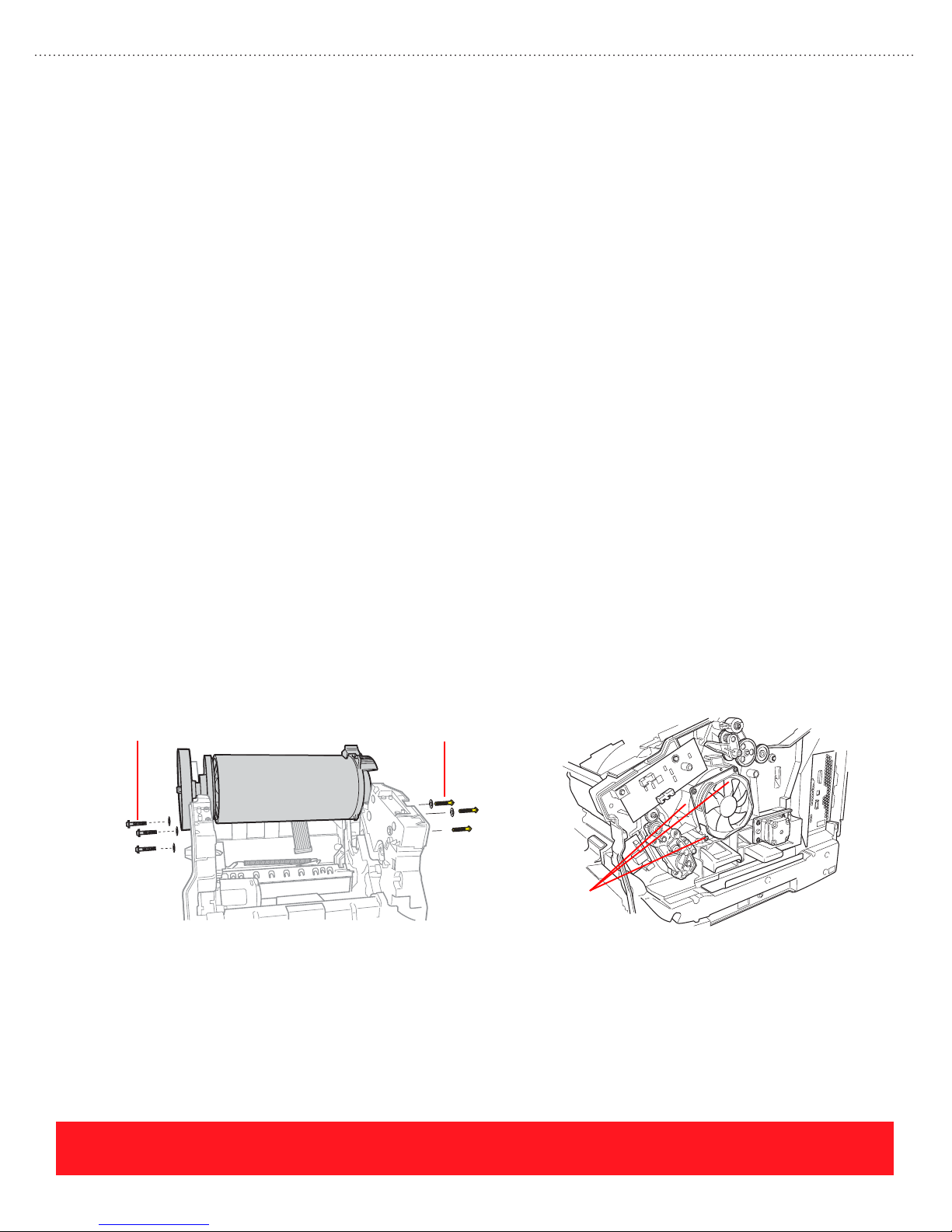
Drum Assembly
This topic provides general Drum Assembly replacement tips and highlights differences between the
procedures for Phaser 8400 and Phaser 8500/8550 printers.
General Drum Assembly Replacement Tips
Closely follow the Replacement Notes provided in the Service Manual disassembly procedure when
replacing the Drum Assembly. Be aware of the following as you install the new assembly:
■ Several torque settings are required to correctly install the screws.
■ Screws must be installed in a specific sequence.
■ Apply grease to the Transfix Load Arms before attaching the Spring Hooks.
■ After replacing the Drum Assembly, always check the Printhead Wiper Assembly alignment.
■ If the Media Drive Gearbox and Motor gears are noisy after reinstalling the assembly, rotate the
Duplex Roller back and forth to seat the gears.
Procedure Differences
The Drum Assembly replacement procedure is similar for Phaser 8400, 8500, and 8550 printers. The
following tips apply when replacing the Phaser 8500/8550 Drum Assembly:
■ Phaser 8500/8550 printers have yellow screws on the right side that are reverse-threaded to avoid
transfix/stripper issues caused when tightening the right- and left-side screws in the same
direction.
■ Technicians must install the reverse-threaded screws in the order specified by the Service Manual.
■ Observe the torque specification on the Phaser 8500/8550 drum fan screws to avoid bending it,
because a metal shroud is not installed behind the fan. (Phaser 8400 printers have a metal shroud.)
Standard Screws
(Left End Of Drum)
Reverse-Threaded Screws
(Right End Of Drum)
Do Not Overtighten
Drum Fan Screws
page 86
PHASER 8550, 8500, & 8400 SERVICE SECTION
Version 1.0
Page 95
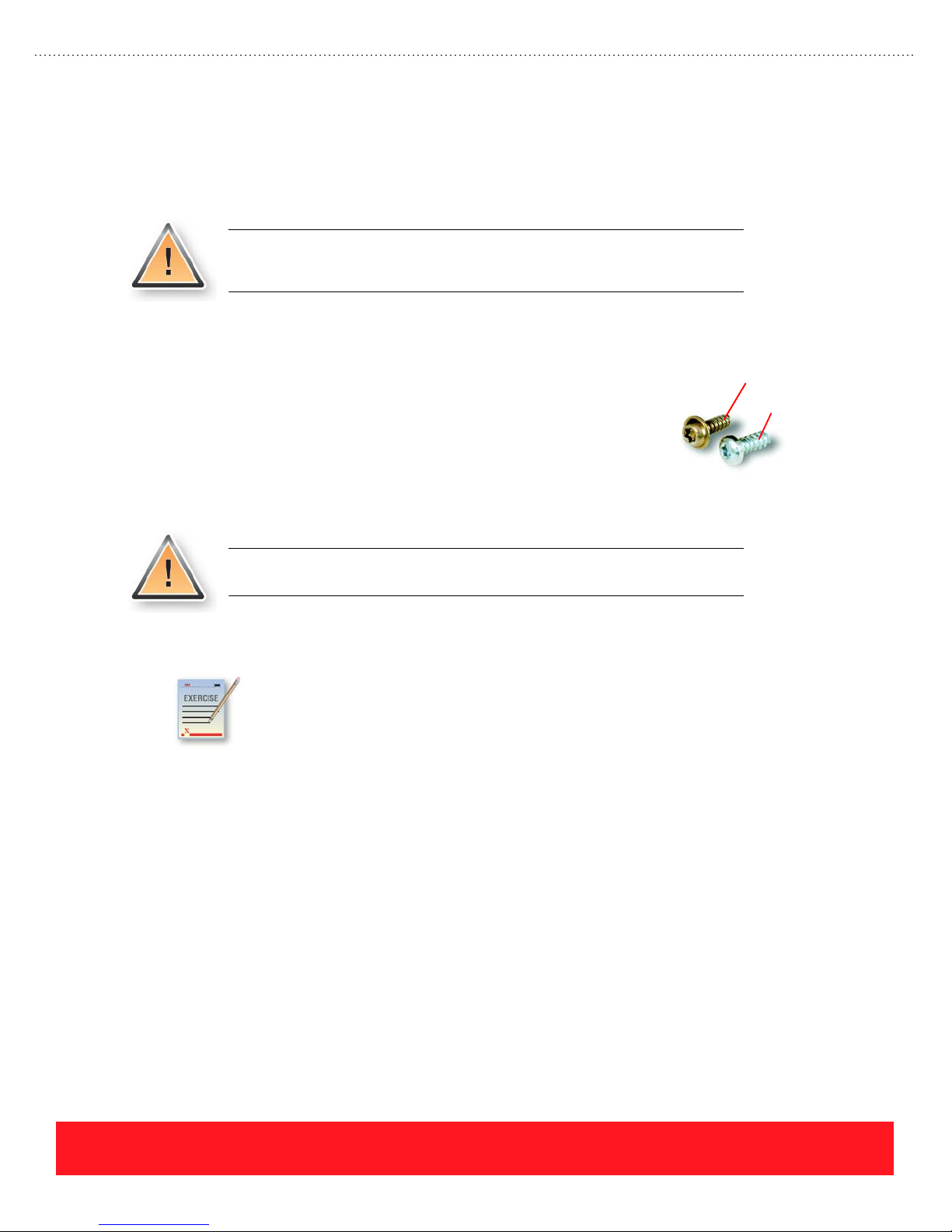
Lubrication
The Lubrication section of the Service Manual provides instructions for lubrication. In general, the printer
requires no periodic lubrication. When lubrication is required, instructions are provided within the
Replacement Notes section of the disassembly procedure.
Tightening Screws
To avoid stripping screw threads in the plastic printer frame, technicians
must use the correct method for installing them. If a thread is stripped, the
hardware kit contains silver-blue tinted repair screws. The repair screws
have a slightly larger diameter than the standard screw. Most screws in the
printer should be tightened to 12 in-lbs of torque using a torque
screwdriver. In some cases, other torque settings are required. Always
refer to the replacement procedures in the Service Manual for the correct
torque settings.
Tightening Screws Review Exercise
Plastic parts will deteriorate when unspecified grease and chemicals are
used, such as WD-40
the grease specified in the Lubrication section of the Service Manual.
®
and Locktite® Threadlocker. To avoid damage, use only
Standard Screw
Repair Screw
To avoid damage when repairing the printer, use a torque screwdriver such as
Xerox part number 003082700 to install the screws.
Use the General Notes on Disassembly section of your Service Manual to answer the following
questions.
The answers for this exercise are located in the Appendix on page 93.
1. How should you start screws when using a power driver for installation?
_____________________________________________________________________________
2. What is the torque specification for installing most screws that thread into plastic? ___________
3. What should you do if you strip screw threads in the plastic frame? _______________________
_____________________________________________________________________________
4. Which part has screws that should be tightened using 6 in-lbs? __________________________
PHASER 8550, 8500, & 8400 SERVICE SECTION
Version 1.0
page 87
Page 96
Disassembly Lab
1. Remove and then reinstall the Printhead Wiper Assembly.
2. Remove and then reinstall the Drum Assembly.
3. Power on the printer and verify normal operation.
To avoid damage to the printer, refer to the Service Manual for disassembly
and assembly instructions.
Your Next Step
You have completed the Phaser 8550, 8500, & 8400 Self-Study Guide.
If a printer is available, use the Service Parts Disassembly section of your Service Manual to
remove the Printhead Wiper Assembly and Drum Assembly. While replacing these two
assemblies, you will remove and re-install most of the printer’s service parts. To complete the
disassembly lab:
Return to the training CD-ROM and complete the Service Self-Check to
practice for the online test. Then, use the online Testing Center to access the
certification test.
We highly value your feedback and often use customer ideas to improve our
training products. Please visit the Resources section of the training CD-ROM
and fill out the Training Feedback Survey.
page 88
PHASER 8550, 8500, & 8400 SERVICE SECTION
Version 1.0
Page 97

Phaser 8550, 8500, & 8400 Service Self-Study Guide
APPENDIX
Answers to Overview Exercises
Speed & Quality Review Exercise
1. If a customer indicates that his printer is too slow when printing transparencies, what solution
could you recommend?
■ Changing the Print-Quality Mode to Fast Color or Standard increases the print speed for
transparencies, but reduces the saturation of ink on the page
2. A customer is printing letterhead from Tray 1 using the High Resolution/Photo Print-Quality
Mode. What are two suggestions you can her them to increase the print speed?
■ Increase the print speed by using Tray 2 instead of Tray 1 and by selecting a different
Print-Quality Mode
3. What advice would you give a customer who has ordered more cyan ink because her printer ran
out of cyan, but she has an immediate need to print a draft copy of her document?
■ Cancel the current job and resend the job using the “Black & White” color correction mode
Media Support Review Exercise
1. 8.5 x 11 inch sheets of 32 lb. bond:
■ Use any tray
2. A6-size sheets of 20 lb. plain paper:
■ Use any Tray 1 only
3. Phaser Color Printing Labels:
■ Use any tray
4. 100 mm x 200 mm custom-size sheets of 32 lb. plain paper:
■ Use any Tray 1 only
PHASER 8550, 8500, & 8400 APPENDIX
Version 1.0
page 89
Page 98

Answers to Setup Exercises
Setup Review Exercise
1. According to the Setup Guide, what is the first step of the installation process?
■ The first step is to watch the setup video.
2. How many people are required to lift the printer?
■ Two people are required to lift the printer.
3. Which sides of the printer can be within 10 cm (4 in) of the wall?
■ The left and rear sides of the printer can be within 10 cm (4 in) of the wall.
4. The surface on which the printer is placed must be level from side-to-side within how many inches?
■ The surface must be level within 0.5 inches or 1.2 centimeters.
Loading Paper Review Exercise
1. To print envelopes with side flaps from Tray 1:
■ The correct position for the flap is face up and to the left.
2. To print letterhead on one side from Tray 2:
■ Position the logo face up and toward the front of the tray.
3. Select each envelope style that is supported for printing.
■ The supported envelope styles are A, B, and D.
Answers to Care Exercises
Troubleshooting Exercise
1. On November 11, 2003, a customer explains that their printer is using too much ink. The printer’s
warranty period began August 30, 2003. Based on the Printer Status Page, what advice would you
offer the customer?
■ The printhead has been cleaned 51 times and the power has been cycled 122 times. Explain that the
customer should leave their printer turned on.
2. On October 29, 2003, a customer contacts you regarding print-quality problems caused by their
Standard-Capacity Maintenance Kit. Use the information on the Printer Status Page to determine
if the kit has failed during the warranty period.
■ The Maintenance Kit has generated just 1570 pages and was installed on August 27, 2003. In this
example, replace the kit under warranty because it failed to produce 10,000 pages or to last at least
90 days from installation.
3. Is average ink coverage during the last 30 days greater than or less than 20%?
■ Because the coverage for each color is <5%, the total coverage is less than 20%. Total coverage
equals the sum of the percent coverage for each color.
page 90
PHASER 8550, 8500, & 8400 APPENDIX
Version 1.0
Page 99

4. What advice would you give a customer who has ordered more cyan ink because her printer ran
out of cyan, but she has an immediate need to print a draft copy of her document?
■ Cancel the current job and resend the job using the “Black & White” color correction mode.
5. Before authorizing onsite service, the Knowledge Base indicates the Maintenance Kit should be
replaced to correct a specific print-quality problem. The customer has FAXED a copy of their
Printer Status Page, and they are certain someone in the office installed a new kit. Use the Printer
Status Page to determine if the kit has actually been replaced.
■ The original kit is still installed because the value for “Total Maintenance Kit Installed” is 1.
Cleaning Review Exercise
1. According to the Phaser 8500/8550 Troubleshooting Print Quality Page, how many times should
users select “Basic” before they should select “Advanced” from the Eliminate Light Stripes menu?
■ Use the Basic procedure 2 times.
2. Which troubleshooting step should not be used even though it appears on the embedded
Phaser 8500/8550 Troubleshooting Print Quality Page?
■ Step 8, turning off the printer for 4 hours, is no longer a recommended troubleshooting step.
3. A hidden push button sequence is used to select Jet Substitution mode on Phaser 8500/8550 printers.
■ False, Jet Substitution is located in the Eliminate Light Stripes menu.
4. When the print-quality problem depicted to the right occurs, which part of the printer should be cleaned?
■ Clean the paper path to resolve smudging or smearing problems.
5. When the print-quality problem depicted to the right occurs, which part of the printer should be cleaned?
■ Clean the Printhead to resolve light vertical stripes caused by weak or missing jets.
Moving and Shipment Review Exercise
1. What is the best way to power down the printer before moving it?
■ Select Shutdown For Moving Printer to ensure the Printhead is locked and the ink is solidified
before moving the printer.
2. How much time should be allowed for cooling before moving the printer to avoid ink spills?
■ Allow 30 minutes for cooling before moving the printer.
3. If the Printhead Lock Indicator is not raised, why should you avoid moving the printer?
■ The Printhead can be damaged if it is not locked prior to movement or shipping.
4. How many people are required to lift the printer?
■ Two people are required to lift the printer.
5. Name two items you must remove before packaging the printer for shipment.
■ Always remove the Maintenance Kit and Waste Tray.
PHASER 8550, 8500, & 8400 APPENDIX
Version 1.0
page 91
Page 100

Answers to Service Exercises
Error Codes Review Exercise
1. Locate and record the two most likely failures when the Control Panel displays the message
“POST Failure 11.02.
■ Check the EEPROM orientation and then replace the EEPROM.
2. After replacing the Media Drive Assembly, the printer reports error code “37,015.40”. Use the
Service Manual to determine which wiring harness is disconnected.
■ The Drum Cooling Fan is disconnected.
3. A Phaser 8400 printer is jamming on every page. The Jam History shows several instances of the
“B3T” jam code. Use the Service Manual to determine which sensor is responsible for this error.
■ The Preheat Exit Sensor is timing out during the transfix process.
Print Quality Review Exercise
1. Stuck Preheater plate:
■ Stuck Preheater plates can cause a light, wide band.
2. Defective Printhead Wiper:
■ A defective Printhead Wiper Assembly can cause a missing jet.
3. Unsupported media:
■ Unsupported media can cause wrinkling.
4. Dirty Drum Temperature Sensor:
■ Dirt or debris located beneath the Drum Temperature Sensor can cause loss of detail, such as the
missing thin line.
Printhead Troubleshooting Checklist Exercise
1. What information are you checking for in Step 1 of the checklist?
■ Look for the evidence of non-Xerox ink usage.
2. If the printer has error code 13,197.4x, name two troubleshooting steps to complete before
replacing the Printhead.
■ For error code 13,197.4x, reseat the gray Printhead Data Cable and replace the Electronics Module.
3. Which part, when defective, will cause streaks or smudges of ink on the Printhead faceplate?
■ A defective Printhead Wiper Assembly causes streaks or smudges of ink on the Printhead faceplate.
4. If the Printhead has weak or missing jets, how many times should you run Eliminate Light Stripes
using the Control Panel?
■ Run the Eliminate Light Stripes sequence up to 3 times.
5. Under what conditions should the Printhead be replaced instead of using Jet Substitution mode?
■ Replace the Printhead if the customer uses Billing Meters, the missing jets are adjacent, or if the
customer prints using mainly the Fast Color or Standard Print-Quality modes.
page 92
PHASER 8550, 8500, & 8400 APPENDIX
Version 1.0
 Loading...