

Page 1
Phaser® 4600/4620
Laser Printer
Phaser® 4600/4620
Service Manual
Xerox Internal-Use Only
Page 2

Phaser 4600/4620 Printer Service Manual
Service Documentation
Phaser 4600/4620 Printer Service Manual
705P01287
Revision - Xerox Internal Use Only
5/2011
Acrobat®, Adobe® Reader®, Adobe Type Manager®, ATM™, Illustrator® PageMaker®, Photoshop®, PostScript®, Adobe Brilliant® Screens, Adobe Garamond®, Adobe Jenson™,
Birch®, Carta®, IntelliSelect®, Mythos®, Quake®, and Tekton® are trademarks of Adobe Systems Incorporated in the United States and/or other countries.
Apple®, AppleTalk®, Bonjour®, EtherTalk®, LaserWriter®, LocalTalk®, Macintosh®, Mac
OS®, TrueType®, Apple Chancery®, Chicago®, Geneva®, Monaco®, New York® , and QuickDraw® are trademarks of Apple Computer, Inc. in the United States and/or other countries.
HP-GL®, HP-UX®, and PCL® are trademarks of Hewlett-Packard Corporation in the United
States and/or other countries.
Xerox Corporation
Customer and Service Training and Information
26600 Parkway - Bldg. 60
P.O. Box 1000, M/S 7060-776
Wilsonville, OR 97070-1000
NOTICE: All service documentation is supplied to Xerox external cu stomers for informational
purposes only. Xerox service documentation is intended for use by certified, product trained
service personnel only. Xerox does not warrant or represent that such documentation is complete, nor does Xerox represent or warrant that it will notify or provide to such customer any
future changes to this documentation. Customer performed service of equipment, or modules,
components or parts of such equipment may affect the warranty offered by Xerox with respect
to such equipment. You should consult the applicable warranty for its terms regarding customer or third party provided service. If the customer services such equipment , modules, com ponents or parts thereof, the customer releases Xerox from any and all liability for the customer
actions, and the customer agrees to indemnify, defend and hold Xerox harmless from any third
party claims which arise directly or indirectly from such service.
Unpublished rights reserved under the copyright laws of the United States. Contents of this
publication may not be reproduced in any form without permission of Xerox Corporation.
Copyright protection claimed includes all forms of matters of copyrightable materials and information now allowed by statutory or judicial law or hereinafter granted, including without limitation, material generated from the software programs which are displayed on the screen such
as styles, templates, icons, screen displays, looks, etc.
IBM® and AIX® are trademarks of International Business Machines Corporation in the U nited
States and/or other countries.
Windows®, Vista™, Windows Server™, and Wingdings® are trademarks of Microsoft Corporation in the United States and/or other countries.
Novell®, NetWare®, NDPS®, NDS®, Novell Directory Services®, IPX™, and Novell Distributed Print Services™ are trademarks of Novell, Incorporated in the United States and/or other
countries.
SunSM, Sun Microsystems™, an d Solaris™ are trademarks of Sun Microsystems, Incorporated in the United States and/or other countries.
SWOP® is a trademark of SWOP, Inc.
UNIX® is a trademark in the United States and other countries, licensed exclusively through X/
Open Company Limited.
As an ENERGY STAR® partner , Xerox Corporation has determined that this product meets the
ENERGY STAR guidelines for energy efficiency. The ENERGY STAR name and logo are registered U.S. marks.
PANTONE® Colors generated may not match PANTONE-identified standards. Consult current
PANTONE Publications for ac curate color. PANTONE® and other Pantone, Inc. trademarks
are the property of Pantone, Inc. © Pantone, Inc., 2000.
Xerox technical training materials and service manuals are intended for use by authorized
Xerox service technicians and service partners only and are not for resale. These materials
may not be distributed, copied or otherwise reproduced without prior written consent from
Xerox Corporation.
© 2010 Xerox Corporation. All rights reserved. XEROX® and XEROX and design®, P haser®,
PhaserSMART®, DocuCard®, DocuSP®, FreeFlow® CentreWare®, infoSMART®, Made For
Each Other®, PagePack™, ColorCube®, ProfitAccelertor™, and Walk-Up™ are trademarks of
Xerox Corporation in the United States and/or other countries.
Page 3

About This Manual .............................................................................. ......... .... .... .... ....... iii
How To Use This Manual................................................................................................ iii
Service Safety Summary......................................................... ........................................ iv
Symbols Used On The Product....................................................................................... v
Voltage Measurement and Specifications....................................................................... vi
Health and Safety Incident reporting ............................................................................... vi
Regulatory Specifications................................................................................................ vii
Translation of Warnings .................................................................................................. viii
Phaser 4600/4620 Overview........................................................................................... x
Printer Options................................................................................................................ xi
Control Panel Layout........................................................... ................................... ......... xiii
Routine Maintenance Items ............................................................................................ xiv
Consumables.................................................................................................................. xiv
Introduction
Revision - Xerox Internal Use Only
Phaser 4600/4620 Printer Service Manual
5/2011
i
Introduction
Page 4

About This Manual
The Phaser 4600/4620 Printer Service Manual is part of a multinational service documentation
system organized in the standard Xerox EDOC serv ice manual format. This manual is the primary document used for diagnosing, repairing, maintaining, and troubleshooting these sys tems. The Service Manual is the controlling publication for a service call. Information on using
this document is found in the Introduction section. To ensure understanding of this product,
complete the Xerox Service Training Program for this particular printer.
Organization
Section titles and the information contained in each is presented in the following paragraphs:
Section 1 Service Call Procedures
This section is used to start and complete a service call. The procedures in this section will
either direct you to a Repair Analysis Procedure (RAP), or identify a faulty component or subassembly.
Section 2 Status Indicator Repair Analysis Procedures
This section contains the Repair Analysis Procedures (RAPs) and checkouts necessary to
diagnose, isolate and repair faults other than image quality faults.
Section 3 Image Quality
This section contains the Image Quality Repair Analysis Procedures (IQ RAPs), checkouts and
setup procedures necessary to diagnose, isolate and repair image quality faults.
Section 4 Repairs/Adjustments
This section contains the instructions for removal, replacement, and adjus tm ent of parts within
the machine.
How To Use This Manual
Always start with the Service Call Procedures, Section 1. Perform Initial Actions and verify the
problem, then follow the directions given.
How to Differentiate Between Machine Variants
The machine will be identified in this manual by the model identifier 4600/4620.
When a procedure, parts list description or other reference is unique amongst different models
of machine, the appropriate model designator is indicated. Any artwork is also specific.
NOTE: This manual services all configurations of the machine. Ignore references to options
not installed on the machine.
Warnings, Cautions and Notes
WARNING
A warning is used whenever an operating or main tenance procedure, practice, condition or statement, if not strictly observed, could result in personal injury.
A translated version of all warnings is in Translation of Warnings.
CAUTION
A caution is used whenever an operation or maintenance procedure, practice, condition or
statement, if not strictly observed, could result in damage to the equipment.
NOTE: A note is used where it is essential to highlight a procedure, practice, condition or statement.
Section 5 Parts List
This section contains the detailed and illustrated spare parts list. Any part that is spared or that
must be removed to access a spared part is illustrated.
Section 6 General Procedures / Information
This section contains all other procedures, product specifications and general information.
Section 7 Wiring Data
This section contains the wiring diagrams.
Section 8 Accessories
This section contains details of any accessories that the machine may have.
Publication Comments Sheet
A Publication Comment Sheet is provided at the rear of the hardcopy manual.
Component Names
Names of parts that appear in the disassembly procedures may not be exactly the same as the
names that appear on the part or listed in the Parts List. For example; a part called the Registration Chute Assembly may appear on the Parts List as Assembly, Chute REGI.
Revision - Xerox Internal Use Only
Phaser 4600/4620 Printer Service Manual
5/2011
iii
Introduction
About This Manual, How To Use This Manual
Page 5

Service Safety Summary
General Guidelines
For qualified service personnel only: Refer also to the preceding Electrical Safety.
Avoid servicing alone: Do not perform internal service or adjustment of this product unless
another person capable of rendering first aid or resuscitation is present.
Use care when servicing with power applied: Dangerous voltages may exist at several points in
this product. To avoid personal injury, do not touch exposed connections and components
while power is on. Disconnect power before removing the power supply shield or replacing
components.
Do not wear jewelry: Remove jewelry prior to servicing. Rings, necklaces and other metallic
objects could come into contact with dangerous voltages and currents.
Electrical Safety
• Use the Power Cord supplied with the printer.
• Plug the Power Cord directly into a properly grounded electrical outlet.
• Do not use a ground adapter plug to connect the printer to an electrical outlet that does
not have a ground connection terminal.
• Do not use an extension cord or power strip.
• Do not place the system in an area where people might step on the power cord.
• Do not place objects on the power cord.
• Do not block the ventilation openings. These openings are provided to prevent overheat ing of the printer.
• Do not drop paper clips or staples into the printer.
Operational Safety
The printer and supplies were designed and tested to meet strict safety requirements. These
include safety agency examination, approval, and compliance with established environmental
standards.
Warning Labels
Read and obey all posted warning labels. Throughout the printer, warning labels are displayed
on potentially dangerous components. As you service the printer, check to make certain that all
warning labels remain in place.
Safety Interlocks
Make sure all covers are in place an d all interlock switches are functioning correc tly after you
have completed a printer service call. If you bypass an interlock switch during a service call,
use extreme caution when working on or around the printer.
Pay attention to these safety guidelines to ensure the continued, safe operation of the printer.
• Use the supplies specifically designed for your system. The use of unsuitable materials
may cause poor performance and a possible safety hazard.
• Follow all warnings and instructions marked on, or supplied with, the system, options and
supplies.
NOTE: The Total Satisfaction Guarantee is available in the United States and Canada. Coverage may vary outside these areas; please contact your local representative for details.
Maintenance Safety
• Do not attempt any maintenance procedure that is not specifically described in the doc umentation supplied with the printer.
• Do not use aerosol cleaners. The use of supplies that are not approved may cause poor
performance and could create a hazardous condition.
• Do not burn any consumables or routine maintenance items. For inform ation on Xerox
supplies recycling programs, go to www.xerox.com/gwa.
Introduction
Service Safety Summary
5/2011
iv
Revision - Xerox Internal Use Only
Phaser 4600/4620 Printer Service Manual
Page 6
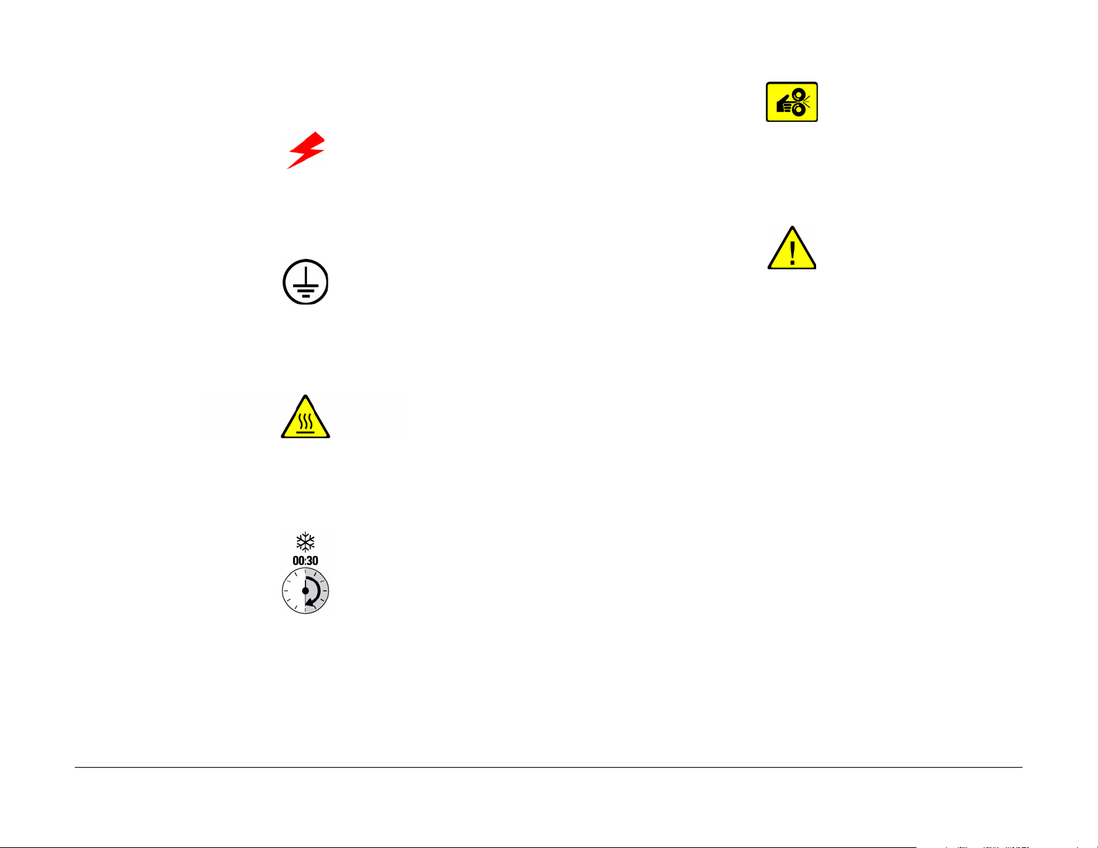
Symbols Used On The Product
The following precautionary symbols may appear on the machine.
This symbol indicates Danger High Voltage.
Figure 1 High Voltage Symbol
Protective Ground (Earth) symbol.
Figure 2 Protective Ground (Earth) Symbol
This symbol indicates hot surface. Use caution to avoid personal injury.
Avoid pinching fingers in the printer. Use caution to avoid personal injury.
Figure 5 Pinch Injury Symbol
Use caution (or draws attention to a particular component). Refer to the manual(s) for information.
Figure 6 Use Caution Symbol
Figure 3 Hot Surface Symbol
The surface is hot while the printer is running. After turning off the power, wait 30 minutes.
Figure 4 Wait 30 Minutes Symbol
Revision - Xerox Internal Use Only
Phaser 4600/4620 Printer Service Manual
5/2011
v
Introduction
Symbols Used On The Product
Page 7

Voltage Measureme n t and S pec if ica t ions
Measurements of DC voltage must be made with reference to the specified DC Common,
unless some other point is referenced in a diagnostic procedure. All measurements of AC voltage should be made with respect to the adjacent return or ACN wire.
Table 1 Voltage Measurement and Specifications
Voltage Specification
Input Power 220 V 198 VAC TO 254 VAC
Input Power 100 V 90 VAC TO 135 VAC
Input Power 120 V 90 VAC TO 135 VAC
+5 VDC +4.75 VDC TO +5.25 VDC
+24 VDC +23.37 VDC TO +27.06 VDC
Logic Voltage Levels
Measurements of logic levels must be made with reference to the specified DC Common,
unless some other point is referenced in a diagnostic procedure.
Table 2 Logic Levels
Voltag e H/L Specification
+5 VDC H = +3.00 V or greater
L = below 0 .8 V
+3.3V H = +2 V or greater
L =below 0.8 V
DC Voltage Measurement in RAPs
The RAPs have been designed so that when it is required to use the DMM to measure a DC
voltage, the first test point listed is the location for the red (+) meter lead and the second test
point is the location for the black meter lead. For example, the following statement may be
found in a RAP.
There is +5 VDC from P/J7 to P/J68.
In this example, the red meter lead would be placed on P/J7 and the black lead on P/J68.
If a second test point is not given, it is assumed that the black meter lead may be attached to
chassis ground.
Health and Safety Incident reporting
I. Summary
This section defines requirements for notification of health and safety incidents involving Xerox
products (equipment and materials) at customer locations.
II. Scope
Xerox Corporation and subsidiaries worldwide.
III. Objective
To enable prompt resolution of health and safety incidents involving Xerox products and to
ensure Xerox regulatory compliance.
IV. Definitions
Incident:
An event or condition occurring in a customer acco unt that has resulted in injury, illness or
property damage. Examples of incidents include machine fires, smoke generation, physical
injury to an operator or service representative. Alleged events and product conditions are
included in this definition.
V. Requirements
Initial Report:
1. Xerox organizations shall establish a process for individuals to report product incidents to
Xerox Environment Health & Safety within 24 hours of becoming aware of the event.
2. The information to be provided at the time of reporting is contained in Appendix A (Health
and Safety Incident Report involving a Xerox product).
3. The initial notification may be made by any of the following methods:
• For incidents in North America and Developing Markets West (Brazil, Mexico, Latin
American North and Latin American South):
– Phone* Xerox EH&S at: 1-800-828-6571.
– Electronic mail Xerox EH&S at: Doris.Bush@xerox.com.
– Fax Xerox EH&S at: 1-585-422-6449 [intelnet 8*222 6449].
• For incidents in Europe and Developing Markets East (Middle East, Af rica, India,
China and Hong Kong):
– Phone* Xerox EH&S at: +44 (0) 1707 353434.
– Electronic mail Xerox EH&S at: Elaine.Grange@xerox.com.
– Fax Xerox EH&S at: +44 (0) 1707 353914 [intelnet 8*668 3914].
*Initial notification made by phone must be followed within 24 hours by a completed incident report and sent to the indicated electronic mail address or fax number.
NOTE: If sending a fax, please also send the original via internal mail.
Introduction
Voltage Measurement and Spec ifications, Health and
5/2011
vi
Revision - Xerox Internal Use Only
Phaser 4600/4620 Printer Service Manual
Page 8

Responsibilities for resolution:
1. Business Groups/Product Design Teams responsible for the product involved in the incident shall:
a. Manage field bulletins, customer correspondence, product recalls, safety retrofits.
b. Fund all field retrofits.
2. Field Service Operations shall:
a. Preserve the Xerox product involved and the scene of the incident inclusive of any
associated equipment located in the vicinity of the incident.
b. Return any affected equipment/part(s) to the location designated by Xerox EH&S
and/or the Business Division.
c. Implement all safety retrofits.
3. Xerox EH&S shall:
a. Manage and report all incident investigation activities.
b. Review and approve proposed product corrective actions and retrofits, if necessary.
c. Manage all communications and correspondence with government agencies.
d. Define actions to correct confirmed incidents.
Regulatory Specifications
Xerox has tested this product to elec tromagnetic emission and immunity standards. These
standards are designed to mitigate interference caused or receiv ed by this product in a typical
office environment.
United States (FCC Regulations)
The Phaser 4600/4620 has been tested and found to comply with the limits for a Class A digital
device pursuant to Part 15 of the FCC Rules. These limits are designed to provide reasonable
protection against harmful interference in a commercial installation. This equipment generates,
uses, and can radiate radio frequency energy. If it is not installed and used in accordance with
these instructions, it may cause harmful interference to radio communications. Operation of
Class A equipment in a residential area is likely to cause harmful interference in which case the
user will be required to correct the interference at his/her own expense. There is no guarantee
that interference will not occur in a particular installation.
If this equipment does cause harmful interference to radio or television reception, which can be
determined by turning the equipment Off and O n, the user is encou raged to try to correct the
interference by one or more of the following measures:
• Reorient or relocate the receiver.
• Increase the separation between the equipment and receiver.
• Connect the equipment into an outlet on a circuit different from that to which the receiver
is connected.
• Consult the dealer or an experienced radio/television technician for help.
Any changes or modifications not expressly approved by Xerox could void the user's authority
to operate the equipment. To ensure compliance with Part 15 of the FCC rules, use shielded
interface cables.
Revision - Xerox Internal Use Only
Phaser 4600/4620 Printer Service Manual
Canada (Regulations)
This Class A digital apparatus (4600/4620) complies with Canadian ICES-003.
Cet appareil numérique (4600/4620) de la classe A est conforme
Canada.
5/2011
vii
Health and Safety Incident reporting, Regulatory
à la norme NMB-003 du
Introduction
Page 9

European Union
CE Mark
The CE mark applied to this product symbolizes Xerox’s
declaration of conformity with the following applicable Directives of the European Union as of the dates indicated:
Figure 1 CE Symbol
December 12, 2006: Low Voltage Directive 2006/95/EC
December 15, 2004: Electromagnetic Compatibility Directive 2004/108/EC
This product, if used properly in accordance with the user's instructions, is neither dangerous
for the consumer nor for the environment.
To ensure compliance with European Union regulations, use shielded interface cables.
A signed copy of the Declaration of Conformity for this product can be obtained from Xerox.
Translation of Warnings
WARNING
Switch off the electricity to the machine. Di sconnect the power cord from th e customer
supply while performing tasks that do not need electricity. Electricity can cause death or
injury . Moving parts can cause injury.
DANGER : Mettez la machine hors tension. Déconnectez le cordon d'alimentation de
l'alimentation du client lorsque vous réalisez des tâches qui ne nécessitent pas d'électricité. L'électricité peut être à l'origine de blessures, voire d'un accident mortel. Les
pièces amovibles peuvent être à l'origine de blessures.
AVVERTENZA: Spegnere la macchina. Scollegare il cavo di alimentazione dall'alimentatore quando si eseguono attività che non richiedono elettricità. L'elettricità può causare
morte o lesioni personali. Le parti in movimento possono causare lesioni personali.
VORSICHT: Schalten Sie die Stromversorgung der Maschine ab. Ziehen Sie das Stromkabel ab, wenn Sie Aufgaben ausführen, für die keine Stromversorgung benötigt wird.
Stromschläge können Todesfällen oder Verletzungen verursachen. Bewegliche Teile
können zu Verletzungen führen .
AVISO: Apague la electricidad de la máquina. Desconecte el cable de alimentación eléctrica de la toma de pared mientras esté realizando tareas que no necesiten corriente. La
electricidad puede causar daños o la muerte. Las partes móviles pueden causar daños.
WARNING
Do not work in a confined space. 1 m (39 inches) space is needed for safe working.
DANGER : Ne pas travailler dans un espace restreint. 1 mètre d'espace est nécessaire
pour un dépannage en toute sécurité.
AVVERTENZA: Non lavorare in uno spazio limitato; è necessario uno spazio di almeno
un metro attorno alla macchina per la sicurezza dell'operatore.
VORSICHT: Nur mit ausreichendem Bewegungsspielraum (1 m) arbeiten.
AVISO: No trabaje en un espacio reducido. Se necesita 1 metro de espacio para trabajar
con seguridad.
WARNING
Use safe handling procedures when removing the module. Re fer to GP 16. The module
is heavy.
DANGER: Conformez-vous aux procédures de manipulation de sécurité p our le retrait
du module. Reportez-vous à GP 16. Le module est lourd.
AVVERTENZA: Utilizzare procedure di gestione sicure durante la rimozione del modulo.
Vedere GP 16. Il modulo è pesante.
VORSICHT: Verwenden Sie sichere Vorgehensweisen zum Entfernen des Moduls. Siehe
auch GP 16. Das Modul ist sehr schwer.
AVISO: Utilice los procedimientos de seguridad cuando elimine el módulo. Consulte el
GP 16. El módulo es pesado.
Introduction
Regulatory Specifications, Translation of Warnings
5/2011
viii
Revision - Xerox Internal Use Only
Phaser 4600/4620 Printer Service Manual
Page 10

WARNING
Follow the service procedure exactly as written. Use of controls or adjustments other
than those specified in this manual, may result in an exposure to invisible laser radiation. During servicing, the invisible laser radiation can cause eye damage if looked at
directly.
DANGER : Les procédures de dépannage doivent être suivies à la lettre. Si les réglages
ou vérifications ne sont pas effectués suivant les instructions de ce manuel, il peut y
avoir un risque d'exposition dangereuse au faisceau laser. Celui-ci peut provoquer des
lésions oculaires s'il est observé directement.
AVVERTENZA: Eseguire le procedure di servizio esattamente come descritto. L'utilizzo
di dispositivi di controllo o di registrazione diversi da quelli riportati in questo manuale
potrebbe comportare un'esposizione a radiazioni laser invisibili. Tali radiazioni possono
danneggiare gli occhi se si guarda direttamente il fascio laser durante gli interventi di
servizio.
VORSICHT: Die Wartungsarbeiten genau den Anweisungen entsprechend durchführen.
Der Umgang mit Steuer- oder Bedienelementen, deren Verwendung nicht ausdrücklich
in diesem Handbuch angewiesen wurde, kann dazu führen, dass unsichtbare Laserstrahlung frei gesetzt wird. Direkter Blickkontakt mit dem Laserstrahl kann bleibende
Augenschäden verursachen.
AVISO: Siga los procedimientos de mantenimiento tal como están descritos. El uso de
controles o ajustes no especificados en este manual puede tener como resultado la
exposición a radiación láser invisible. Durante las operaciones de mantenimiento, la
radiación de láser invisible puede causar daños en los ojos si se mira directamente a
ella.
WARNING
USA and Canada. Do not install this machine in a hallway or exit route that does not
have 1.12 m (44 inches) of space additional to the normal space requirements in front of
the machine. To conform with fire reg ulations this additional 1.12 m (44 inches) of space
is needed in front of the machine in hallway and exit routes.
DANGER : États-Unis et Canada. Si cette machine est installée dans un couloir ou une
voie de sortie, 1,12 m (44 pouces) d'espace supplémentaire à l'espace normal doit être
disponible devant la machine conformément aux normes de sécurité d'incendie.
A VVERTENZA: N/A
VORSICHT: N/A
AVISO: Estados Unidos y Canadá. No instale esta máquina en un corredor o ruta de sal-
ida que no tenga 1.12 m (44 pulgadas) de ancho delante de la máquina, sin incluir el
espacio que ocupe la máquina. Este espacio adicional de 1.12 m (44 pulgadas) delante
de la máquina en corredores y rutas de salida es necesario para cumplir los requisitos
de las normas sobre incendios.
WARNING
Use only Xerox materials and components. This product is safety certified using Xerox
materials and components. The use of non Xerox materials and components may invalidate the safety certificate.
DANGER : N'utilisez que des matières premières et des composants Xerox. La sécurité
du produit est assurée dans le cadre de son utilisation avec des matières premières et
des composants Xerox. L'utilisation de matières premières et de composants autres
que ceux de Xerox risque d'invalider le certificat de sécurité.
AVVERTENZA: Utilizzare solo materiali e componenti Xerox per avvalersi della certificazione di protezione. L'utilizzo di materiali e componenti non Xerox può rendere nulla
la certificazione di pr otezione.
VORSICHT: Verwenden Sie nur Materialien und Komponenten von Xerox. Dieses
Produkt besitzt die Sicherheitszertifizierung bei Verwendung von Xerox-Materialien und
-Komponenten. Die Verwendung von Materialien und Komponenten anderer Hersteller
setzt möglicherweise das Sicherheitszertifikat außer Kraft.
AVISO: Utilice solo los materiales y componentes Xerox. Este producto dispone de un
certificado de seguridad si se utilizan los materiales y componentes Xerox. Este certificado de seguridad no será válido si se utilizan materiales y componentes que no sean
de Xerox.
WARNING
Do not touch the fuser while it is hot.
DANGER : Ne pas toucher au four pendant qu'il est encore chaud.
AVVERTENZA: Non toccare il fonditore quando è caldo.
VORSICHT: Fixierbereich erst berühren, wenn dieser abgekühlt ist.
AVISO: No toque el fusor mientras está caliente.
Revision - Xerox Internal Use Only
Phaser 4600/4620 Printer Service Manual
5/2011
ix
Introduction
Translation of Warnings
Page 11

Phaser 4600/4620 Overvi ew
The Phaser 4600/4620 combines a monochrome laser print engine with a multi-purpose Tray 1
(bypass) and universal media tray, Tray 2. The Output Tray holds 500 20lb. sheets facedown.
Phaser 4600/4620 options add memory, media capacity, and functionality . For models not originally equipped, a 160 GB Hard Drive is available. A memory upgrade raises the installed RAM
to the 768 MB maximum. Configurations of up to four 520-Sheet Feeders, or an additional 2
520-sheet feeders and the high-capacity 2000-sheet feeder. On the output side, 500 sheet stapler/stacker or 4-bin, 400-sheet Mailbox are available, Figure 1.
Front View
Rear View
Figure 2 shows features located at the rear of the system.
Figure 1 Front View
Table 1 Front View
1. Finisher (Stacker & Stapler) 10. Tray 2
2. Mailbox 11. Front Door
3. Staple Cartridge Door 12. Top Door
4. IP Board Cover 13. Control Panel
5. Filter Cover 14. Top Cover
6. Printer Stand 15. Toner Cartridge
7. 2000-Sheet Feeder 16. Drum Cartridge
8. Media level Indicator 17. Tray 1 (bypass)
9. 520-Sheet Feeder(s) 18. Tray 1 Media Extension
Introduction
Phaser 4600/4620 Overview
Figure 2 Rear view
Table 2 Rear View
1. Finisher Rear Door 6. Power Switch
2. Rear Door 7. Ethernet Connection
3. Mailbox Rear Door 8. Configuration Card Slot
4. Waste Toner Cartridge Door 9. USB Port
5. AC Input 10. Wireless Network Adaptor Slot
5/2011
x
Revision - Xerox Internal Use Only
Phaser 4600/4620 Printer Service Manual
Page 12

Printer Options
Phaser 4600/4620 options include:
• Additional Memory (512 MB)
• Hard Disk
• Wireless network adaptor
• Printer stand
• 520-sheet Feeder
• 2000-sheet Feeder with casters
• Finisher with stapler, 500-sheet stacker .
• Mailbox, 4-bin, 400-sheets
Table 1 lists both Service and Sales part numbers for available options and accessories.
Table 1 Option and Accessory Part Numbers
Item Service Part Number Sales Part Number
520-Sheet Feeder 050K74180 097N01874
2000-Sheet Feeder 059K77920 097N01875
Finisher (500-sheet) 059K77910 097N01876
Mailbox (400-sheet) 050K74190 097N01877
Duplex Unit 022N02484 097N01923
Memory Upgrade 128K01770 097N01878
160MB Hard Disk 007N01651 097N01879
Wireless Network Adaptor 120K03640 097N01880
Stand 078K00870 097N01916
Figure 1 Optional memory
520-Sheet Feeder
The 520-sheet Feeder increases the input capacity of the printer and is attached to the printer
underneath Tray 2. These additional tray combinations are supported:
• One 520-Sheet Feeder (Tray 3)
• Up to 4, 520-Sheet Feeders (Trays 3, 4, 5, and 6)
Hard Disk Drive
The Phaser 4600/4620 supports an internal 160 GB Hard Disk Drive mounted to the IP Board.
Features enabled by Hard Drive installation include:
• Secure Print
•Proof Print
• Save Print
• Disk Collation
Additional Memory
The Phaser 4600/4620 IP Board includes 1 slot for a 512 MB DDR2 DIMM, Figure 1. Memory
must meet these characteristics:
• 200 Pin DDR2 SODIMM
• Unbuffered, Non-parity
The printer’s Configuration page lists the amount of RAM installed in the printer.
Revision - Xerox Internal Use Only
Phaser 4600/4620 Printer Service Manual
5/2011
xi
Figure 2 520-Sheet Feeder
Introduction
Printer Options
Page 13

2000-Sheet Feeder
The 2000-sheet Feeder increases the input capacity of the printer and is attached to the printer
underneath Tray 2 or installed 520-sheet Feeders. These additional tray combinations are supported:
• One 2000-Sheet Feeder (Tray 3)
• Up to 2 520-Sheet Feeders (Trays 3, 4) and 1 2000-Sheet Feeder (Tray 5).
Mailbox
The Mailbox provides four 100-sheet output trays.
Introduction
Printer Options
Figure 3 2000-Sheet Feeder
5/2011
xii
Figure 4 Optional Mailbox
Revision - Xerox Internal Use Only
Phaser 4600/4620 Printer Service Manual
Page 14

Finisher
The finisher provides a 500-sheet, offset Stacker Tray and includes a fixed-head stapler.
Control Panel Layout
The Control Panel consists of one LED, a display window, a keypad, and several buttons.
These buttons are used to navigate the menu system, perform functions, and select modes of
operation for the printer. Table 1 lists the function of each control.
Figure 1 Control Panel
Figure 5 Finisher
Revision - Xerox Internal Use Only
Phaser 4600/4620 Printer Service Manual
T able 1 Control Panel Features
1. Display Displays printer settings, status, messages and menus.
2. Menu Enters Menu Mode and scrolls through the available
3. Back Sends you back one level in the menu.
4. Status LED • Green: Printer is ready to print.
5. OK Accepts the selected settings.
6. Keypad Use to enter alphanumeric characters.
7. Help (?) Additional information.
8. Energy Saver Illuminates when the printer is in Power Saver mode. Press
9. Stop Press to cancel the current activity.
5/2011
xiii
menus.
• Yellow: Startup sequence or error condition.
• Flashing:
– Yellow: Error Condition
– Green: Warming up or Receiving data
to enter or exit from Power Saver mode.
Printer Options, Control Panel Layout
Introduction
Page 15

Routine Maintenance Items
Table 1 Routine Maintenance Items
Item Description Print Life
1. Pick and nudger Rollers 200,000 pages
2. Separator Roller 100,000 pages
3. Transfer Roller 100,000 images
4. Fuser 200,000 images
5. Feed Roller 100,000 pages
Consumables
The rated life expectancy of 4600/4620 consumables is listed in Table 1.
T able 1 Consumable Life Expectancy
Item Description Print Life
1. Standard Toner Cartridge 20,000 cycles
High Capacity Toner Cartridge 30,000 cycles
Starter Toner Cartridge 10,000 cycles
2. Drum Cartridge 60,000 cycles
3. Waste Toner Cartridge Provided with new Toner Cartridge
4. Staple Cartridge 15,000
5. Maintenance Kit (Fuser, Feed Rollers, T ransfer
Roller)
200,000 cycles
Introduction
Routine Maintenance Items
5/2011
xiv
Revision - Xerox Internal Use Only
Phaser 4600/4620 Printer Service Manual
Page 16

Service Call Procedures.................................................................................................. 1-3
SCP 1 Initial Actions........................................................................................................ 1-4
SCP 2 First Call Actions .................................................................................................. 1-4
SCP 3 Normal Call Actions.................................... .................................................... ..... 1-5
SCP 4 Fault Analysis ...................................................................................................... 1-5
SCP 5 Subsystem Maintenance ..................................................................................... 1-6
SCP 6 Final Actions ........................................................................................................ 1-7
SCP 7 Configurations and Options................................................................................. 1-8
1 Service Call Proced ur es
Revision - Xerox Internal Use Only
Phaser 4600/4620 Printer Service Manual
5/2011
1-1
Service Call Procedures
Page 17

Service Call Procedures
This section provides an overview of the steps a service technician should take to service the
printer and attached options. The printer’s diagnostic routines report problems using error messages and fault codes displayed on the Control Panel, logged in the Serv ice Usage Pr ofile, or
by flashing LEDs. These error indications serve as the entry point into the troubleshooting process. System problems not directly indicated by or associated with an error message or fault
code are covered in Section 6, General Procedures. Print-quality problems are covered in Section 3, Image Quality.
The steps listed here are a guide for performing any service on this printer. If you choose not to
use these steps, it is recommended that you start at the appropriate troubleshooting procedure
and proceed from there. When servicing the printer, follow the safety measures detailed in the
Service Safety Summary section.
1. Identify the problem.
• Verify the reported problem does exist.
• Check for any error codes and write them down.
• Print normal customer prints and service test prints.
• Make note of any print-quality problems in the test prints.
• Make note of any mechanical or electrical abnormalities present.
• Make note of any unusual noise or smell coming from the printer.
• Print a Usage Profile, if the printer is able to print.
• View the Engine Error and Jam Histories under the Tools menu.
• Verify the AC input from the wall outlet is within specifications.
2. Inspect and clean the printer.
• Follow the cleaning instructions.
• Verify that the power cord is in serviceable condition.
• Restart the printer to check if the error reoccurs.
3. Find the cause of the problem.
• Use the troubleshooting procedures to find the root cause of the problem.
• Use Service Diagnostics to check the printer and optional components.
• Use the Wiring Diagrams and Plug/Jack Locator to locate test points.
• Take voltage readings as instructed in the troubleshooting procedure.
4. Correct the problem.
• Use the Parts List to locate a part number.
• Use the Repair procedures to replace the part.
5. Final Checkout
• Test the printer to verify the problem is corrected and no new problems arose.
Accessing Engine Fault History
Listed below are three ways in which you can access fault history records.
1. Print (if possible) the Error Message report from the Troubleshooting menu. The error history is listed on the report.
NOTE: Error and fault code definitions of the codes appear in Section 2.
2. If the printer is connected to a network and has a TCP/IP address, view the printer’s web page using a web browser.
a. Open a web browser. b. Enter the printer’s IP address as the URL. c. Selec t Support --> Troubleshooting --> Diagnostics Logs and the fault history
displays.
Revision - Xerox Internal Use Only
Phaser 4600/4620 Printer Service Manual
5/2011
1-3
Service Call Procedures
Service Call Procedures
Page 18

SCP 1 Initial Actions
Initial Actions are used to gather information on the machine performance
SCP 2 First Call Actions
First Call Actions are used for the first service call.
Start a service call with SCP 1 and end with SCP6 Final Actions.
Also refer to SCP 7 Configurations and Options.
Procedure
WARNING
Switch off the electricity to the machine. Di sconnect the power cord fro m th e customer supply while performing tasks that do not need electricity. Electricity can cause death or injury . Moving parts can cause injury.
WARNING
Do not work in a confined space. 1m (39 inches) space is needed for safe working.
NOTE: Ignore any references in this manual to options not installed on the machine.
1. Take note of symptoms or error messages.
2. Ask the operator to describe or demonstrate the problem.
3. Make sure that: a. The power cord is connected to the wall outlet and to the machine. b. Paper is loaded correctly and all paper trays and covers are closed c. If installed, the USB cable or network connection is installed correctly.
4. If available, check the machine service log book for any previous actions that m a y be relevant to the call.
5. If this is the first service call t o this machine perform SCP 2 First Call Actions, otherwise go to SCP 3 Normal Call Actions.
Procedure
1. Check the machine configuration with the customer, refer to SCP 7 Machine Configurations and Options. Check that all required hardware and software is installed and/or enabled.
2. Check that all the relevant machine settings are correctly entered, refer to GP 4 System Administration Tools.
3. If a fault is present, go to SCP 3 Normal Call Actions. If there is no fault present, go to
SCP 6 Final Actions.
4. Enter the machine details and the customer details in the service log.
Service Call Procedures
SCP 1, SCP 2
5/2011
1-4
Revision - Xerox Internal Use Only
Phaser 4600/4620 Printer Service Manual
Page 19

SCP 3 Normal Call Actions
Normal Call Actions are used to determine the reason for the service call.
SCP 4 Fault Analysis
Fault Analysis is used to identify a fault.
Procedure
NOTE: If a fault message appears at any time. Refer directly to the RAP for the fault message and perform the procedure.
If possible, perform the following:
1. Review any defective print samples.
2. Determine that the user accessible settings are correct. If necessary refer to the user documentation.
3. Check all job queues and verify with the customer any requirement to print the documents in memory, before switching off the power or clearing memory.
4. Print the Customer Assistance Report (Call for Assistance), then record the total print count.
5. Go to SCP 4 Fault Analysis.
Procedure
When diagnosing or repairing a fault in a particular subsystem, exercise the machine in all
modes until the fault is determined. In the instance of finding more than one fault or failure, correct one fault before going to the next fault. If no fault is found, go to SCP 5 Subsystem Maintenance.
Fault Codes
If a fault code is displayed, go to the relevant RAP.
UI Faults
If the machine is on but the UI is blank, test the UI with dC330.
Stapler Faults
If the machine has a stapler fault, test the Stapler with dC330.
Image Quality Defects
If the image quality is defective, go to the IQ1 Image Quality Entry RAP.
For image quality specifications, refer to the following:
• IQS 1 Solid Area Density.
• IQS 2 Skew.
• IQS 3 Registration.
Additional Information
If necessary, refer to the following general procedures and information:
• GP 1 Diagnostics Entry
• GP 2 Fault Codes and History Files
• GP 3 System Administration Tools
• GP 4 Reports
• GP 5 Firmware Upgrade
• GP 6 Electrostatic Discharge Prevention
• GP 7 Machine Specifications
• GP 8 General Disassembly Precautions
• GP 9 Service Menu Map
• GP 10 How to Check a Motor
• GP 11 How to Check a Sensor
• GP 12 How to Check a Solenoid or Clutch
• GP 13 How to Check a Switch
• GP 14 Separate System Modules
• GP 15 How to Safely Move heavy Modules
• GP 16 Machine Lubrication
• GP 17 Installation Space Requirements
Revision - Xerox Internal Use Only
Phaser 4600/4620 Printer Service Manual
5/2011
1-5
Service Call Procedures
SCP 3, SCP 4
Page 20

• GP 18 Glossary of Terms
• GP 19 Restriction of Hazardous Substances (RoHS)
• GP 20 First Print Output Time
• GP 21 Media Specifications
• GP 22 Environmental Data
SCP 5 Subsystem Maintenance
Subsystem Maintenance contains information regarding the component life of the machine.
Procedure
WARNING
Switch off the electricity to the machine. Di sconnect the power cord from th e customer supply while performing tasks that do not need electricity. Electricity can cause death or injury . Moving parts can cause injury.
1. Clean the Pick Rollers on every call.
2. Use the Control Panel to check maintenance item counters.
3. Compare the counter values to those listed in Consumables.
4. Advise the customer of any routine maintenance items that are approaching or over the service limit.
Inspection
Rollers
Replace the Rollers when you see any of the following defects:
• Flat spots
• Out of roundness
• Cracked rubber
• Loss of traction (tackiness) causing pick or feed failures
Gears
Replace Gears that show any signs of wear or damage. Look for these problems:
• Thinned gear teeth
• Bent or missing gear teeth; check especially where a metal gear drives a plastic gear.
• Fractured or cracked Gears (oil or incorrect grease on a plastic Gear can cause t he Gear
to crack).
Belts
There are rubber belts in the printer. Inspect the belts for wear. Look for these problems:
Service Call Procedures
SCP 4, SCP 5
• Loose rubber particles below the belts indicate a worn belt.
• Missing teeth in the belts.
• Cracking or moderate fraying; a small amount of fraying is inevitable, so look for other
signs of wear before replacing the belt.
Lubrication
The printer is lubricated during assembly at the factory and does not require periodic lubrication. Some parts require lubrication following replacement. These parts are identified in the
replacement procedures. When lubricating during replacement, use the grease approved for
all Phaser printers.
CAUTION
Plastic parts will deteriorate when unspecified grease and chemicals are used. To avoid damage to the printer, use only Rheolube 768 grease.
• Rheolube 768 Grease: Part Number 070E00890
5/2011
1-6
Revision - Xerox Internal Use Only
Phaser 4600/4620 Printer Service Manual
Page 21

Component Life
The design life of the major components are shown in Table 1. Environmental conditions and actual use will vary these factors. The component life shown in Table 1 is for reference only.
SCP 6 Final Actions
Final Actions are used to evaluate the total operation of the system and to identify the actions required to complete the service call.
Table 1 Component Life Expectancies
Item Description Print Life
1. Pick and nudger Rollers 200,000 pages
2. Separator Roller 100,000 pages
3. Transfer Roller 100,000 images
4. Fuser 200,000 images
5. Feed Roller 100,000 pages
HFSI
The High Frequency Service Items are shown in Table 2.
Table 2 High frequency service items
Item Description
Drum Cartridge The total sides of copies and prints
after the last HFSI reset.
Tray 1 Pick Roller Sheets fed from Tray 1 after last
HFSI reset.
Tray 2 Pick Rollers Sheets fed from Tray 2 after last
HFSI reset.
Transfer Roller Total prints after the last HFSI
reset.
Fuser Total prints after the last HFSI
reset.
Recommended life Reference
10k impressions PL 9.10 Item 1
150k feeds PL 8.10 Item 3
200k feeds PL 8.15 Item 10
100k impressions PL 9.10 Item 2
200k impressions PL 10.10 Item 1
Procedure
Complete the following, if a fault is identified, return to SCP 4 Fault Analysis:
• Perform the end of call subsystem maintenance actions, SCP 5 Subsystem Maintenance.
• Exercise the machine in all modes, printing from all trays. If a fault message is displayed
or some other problem is evident, go to SCP 4 Fault Analysis.
• Make a print of a customer document.
• If any of the customers selections were changed, return t hem to the cu stomers preferred
settings. R e fe r t o GP 4 System Administration Tools.
• At the first service and at any subsequent service where changes are made or options are
added, print the configuration report and store it with machine log book. Discard any previous versions of the configuration report.
• Remove and destroy any copies of test patterns.
• Ensure the machine and service area are clean before leaving the customer premises.
• Provide customer training if required.
Revision - Xerox Internal Use Only
Phaser 4600/4620 Printer Service Manual
5/2011
1-7
Service Call Procedures
SCP 5, SCP 6
Page 22

SCP 7 Configurations and Options
Configurations and Options
Refer to Table 1 for basic configurations and options. This service manual covers all configurations. Within this manual ignore any references to options that are not installed.
Table 1 Phaser 4600/4620 Configurations
Features 4600N 4600DN 4600DT 4620DN 4620DT
Processor Speed 700 MHz 700 MHz 700 MHz 700 MHz 700 MHz Memory* 256 MB 256 MB 256 MB 256 MB 256 MB Print Speed 55 ppm, Letter
52 ppm A4 PS3 Fonts (136) Standard Standard Standard Standard Standard PCL6 Fonts (80 Scalable, 9 Bitmap) Standard Standard Standard Standard Standard USB 2.0 Standard Standard Standard Standard Standard Ethernet Interface 10/100 Base-TX 10/100 Base-TX 10/ 100 Base-TX 10/100 Base-TX 10/100 Base-TX Tray 1 (100 sheet) Standard Standard Standard Standard Standard Tray 2 (520 sheet) Standard Standard Standard Standard Standard Tray 3 (520 sheet) Optional Standard Standard Optional Standard Tray 4 (520 sheet) Optional Optional Optional Optional Optional Tray 5 (2000 / 520-sheet) Optional Optional Optional Optional Optional Tray 6 (520-sheet) Optional Optional Optional Optional Optional Duplex Not available Standard Standard Standard Standard Mailbox (4-bin) Optional Optional Optional Optional Optional Finisher Optional Optional Optional Optional Optional Hard Disk Drive Optional Optional Optional Optional Optional Printer Stand Optional Optional Optional Optional Optional Wireless LAN Optional Opti onal Optional Optional Optional Printer Resolution 600 x 600 dpi
1200 Class * All configurations have one memory slot supporting a 512 MB DDR2 DIMM, to a maximum 768 MB total.
55 ppm, Letter 52 ppm, A4
600 x 600 dpi 1200 Class
55 ppm, Letter 52 ppm, A4
600 x 600 dpi 1200 Class
65 ppm, Letter 62 ppm, A4
600 x 600 dpi 1200 Class
65 ppm, Letter 62 ppm, A4
600 x 600 dpi 1200 Class
Service Call Procedures
SCP 7
5/2011
1-8
Revision - Xerox Internal Use Only
Phaser 4600/4620 Printer Service Manual
Page 23

01-100-00 Top Door Open RAP....................................................................... .... .... .. ..... 2-3
01-102-00 Rear Door Open RAP.................................................................................... 2-3
01-500-00 Finisher Door Open RAP ............................................................................... 2-4
01-700-00 Stapler Door Open RAP ................................................................................ 2-4
01-900-00 Mailbox Rear Door Open RAP....................................................................... 2-5
03-100-00, 03-110-00 Finisher Interface Error RAP ....................................................... 2-5
03-115-00 Mailbox Interface Error RAP. ......................................................................... 2-6
03-120-00, 03-940-00 Tray 3 Communications Fault RAP............................................. 2-6
03-130-00, 03-950-00 Tray 4 Communications Fault RAP............................................. 2-7
03-140-00, 03-960-00 Tray 5 Communications Fault RAP............................................. 2-7
03-150-00, 03-965-00 Tray 6 Communications Fault RAP............................................. 2-8
03-160-00, 03-990-00 HCF Communications Fault RAP................................................ 2-8
03-305-00 Configuration Card Not Present RAP............................................................ 2-9
03-315-00, 03-325-00 Manufacturer ID RAP .................................................................. 2-9
03-335-00 Configuration Card Not Configured RAP....................................................... 2-10
03-410-00 Tray 2 Paper Mismatch RAP ......................................................................... 2-10
03-420-00 Tray 3 Paper Mismatch RAP ......................................................................... 2-11
03-430-00 Tray 4 Paper Mismatch RAP ......................................................................... 2-11
03-440-00 Tray 5 Paper Mismatch RAP ......................................................................... 2-12
03-450-00 Tray 1 Paper Mismatch RAP ......................................................................... 2-12
03-470-00 Tray 6 Paper Mismatch RAP ......................................................................... 2-13
03-480-00 HCF Paper Mismatch RAP............................................................................ 2-13
03-600-00 Memory Failure RAP ..................................................................................... 2-14
03-800-00 Hard Disk Drive Failure RAP......................................................................... 2-15
03-970-00 Software Lock Up RAP.................................................................................. 2-15
04-100-00 Tray 2 Lift Error RAP ..................................................................................... 2-16
04-110-00 Tray 6 Lift Error RAP ..................................................................................... 2-16
04-200-00 Tray 3 Lift Error RAP ..................................................................................... 2-17
04-300-00 Tray 4 Lift Error RAP ..................................................................................... 2-18
04-400-00 Tray 5 Lift Error RAP ..................................................................................... 2-19
04-500-00 Main Motor Failure RAP ................................................................................ 2-20
04-730-00 HCF Lift Error RAP ........................................................................................ 2-21
04-810-00 Rear Fan Failure RAP ................................................................................... 2-22
04-930-00 Main Fan Failure RAP ................................................................................... 2-22
06-100-00, 06-200-00 LSU Error RAP............................................................................ 2-23
07-110-00 Paper Empty at Tray 2 RAP .......................................................................... 2-23
07-120-00 Tray 2 is Open RAP....................................................................................... 2-24
07-130-00 Jam 0 in Tray 2 RAP...................................................................................... 2-24
07-210-00 Paper Empty at Tray 3 RAP .......................................................................... 2-25
07-220-00 Tray 3 is Open RAP....................................................................................... 2-25
07-230-00, 07-231-00 Jam in Tray 3 RAP...................................................................... 2-26
07-310-00 Paper Empty at Tray 4................................................................................... 2-26
07-320-00 Tray 4 is Open RAP....................................................................................... 2-27
07-330-00, 07-331-00 Jam in Tray 4 RAP...................................................................... 2-27
07-410-00 Paper Empty at Tray 5................................................................................... 2-28
07-420-00 Tray 5 is Open RAP....................................................................................... 2-29
07-430-00, 07-431-00 Jam in Tray 5 RAP...................................................................... 2-29
07-500-00 Paper Empty in Tray 1 RAP........................................................................... 2-30
2 Status Indicator RAPS
07-510-00, 07-700-00 Paper Empty at Tray 6................................................................. 2-31
07-520-00 Tray 6 is Open RAP................... .. .... .... ....... .... .... .. .... ....... .... .... .. .... ......... .. .... . 2-31
07-530-00 Jam 0 in Tray 1 RAP...................................................................................... 2-32
07-531-00, 07-630-00 Jam in Tray 6 RAP ...................................................................... 2-32
07-710-00 HCF Out of Paper.......................................................................................... 2-33
07-720-00 HCF Door is Open RAP.............................. .... .. .... .. ....... .... .. .... .. .... ....... .. .... .. . 2-34
07-730-00, 07-731-00 Jam in HCF RAP......................................................................... 2-35
08-100-00 Jam 1 in Registration RAP............................................................................. 2-36
08-110-00 Feed Motor Failure RAP ................................................................................ 2-37
08-200-00 Jam in Tray 2 RAP......................................................................................... 2-37
08-300-00 Jam in Tray 3 RAP......................................................................................... 2-38
08-400-00 Jam in Tray 4 RAP......................................................................................... 2-39
08-450-00 Jam in Tray 5 RAP......................................................................................... 2-40
08-500-00 Jam 2 in Fuser Exit RAP................................................................................ 2-41
08-600-00 Jam 0 in Duplex Unit RAP ............................................................................. 2-42
08-610-00 Jam 1 in Duplex Unit RAP ............................................................................. 2-43
08-650-00 Duplex Unit Not Installed RAP....................................................................... 2-43
08-800-00 Jam in Tray 6 RAP......................................................................................... 2-44
08-850-00 Jam in HCF RAP............................................................................................ 2-45
09-003-00 Developer Motor Failure RAP.......... .... ....... .. .... .. .... ....... .... .. .... .... .. ....... .... .... . 2-46
09-100-00 Toner Low RAP.............................................................................................. 2-46
09-200-00, 09-220-00 Toner Empty RAP........................................................................ 2-47
09-210-00, 09-270-00 Toner (ADC) Sensor Error RAP .................................................. 2-47
09-230-00, 09-250-00 Toner Cartridge CRUM Write/Read Error RAP....... .................... 2-48
09-240-00 Toner Cartridge Communications Error RAP................................................. 2-48
09-271-00 Clean ID (ADC) Sensor RAP......... .... ......... .... .... .... ........... .... .... .... ......... .... ... 2-49
09-290-00 Adjusting Image Quality RAP......................................................................... 2-49
09-300-00 Drum Warning RAP .................................................................................... .. . 2-50
09-400-00 Replace Drum Cartridge RAP........................................................................ 2-50
09-500-00 Toner Cartridge Not Installed RAP ................................................................ 2-51
09-508-00 Waste Toner Cartridge Near Full RAP........................................................... 2-51
09-589-00 Waste Toner Cartridge Full RAP ................................................................... 2-52
09-590-00 Waste Toner Cartridge Not Installed RAP ..................................................... 2-52
09-591-00 Waste Toner Full Sensor Error RAP.............................................................. 2-53
09-600-00 Drum Cartridge Not Installed RAP....................................... .... .... ......... .... ..... 2-53
09-700-00 Toner Supply Error RAP................................................................................ 2-54
09-800-00, 09-810-00 Invalid Toner Cartridge RAP........................................................ 2-54
09-900-00, 09-910-00 Invalid Drum Cartridge RAP........................................................ 2-55
09-920-00 Transfer Unit Error RAP. ................................................................................ 2-55
10-100-00, 10-200-00, 10-300-00 Fuser Thermal Errors RAP........................................ 2-56
10-308-00 Fuser Motor Error RAP.................................................................................. 2-56
10-500-00, 10-510-00 Fuser End of Life RAP................................................................. 2-57
10-700-00, 10-710-00 Fuser Initial Fuse Error RAP........................................................ 2-57
12-100-00, 12-487-00 Jam at Finisher Entrance RAP................................................. ... 2-58
12-200-00 Jam 1 in Finisher RAP ................................................................................... 2-58
12-300-00, 12-488-00, 12-489-00 Jam in Finisher Exit RAP .......................................... 2-59
12-500-00 Full Stack RAP............................................................................................... 2-59
12-605-00 Staples Low RAP........................................................................................... 2-60
Revision - Xerox Internal Use Only
Phaser 4600/4620 Printer Service Manual
5/2011
2-1
Status Indicator RAPS
Page 24

12-610-00, 12-855-00 Out of Staples RAP ..................................................................... 2-60
12-715-00, 12-716-00 Front Jogger Home Fault RAP.................................................... 2-61
12-725-00, 12-726-00 Rear Jogger Home Fault RAP..................................................... 2-61
12-735-00, 12-736-00 Support Finger Home Fault RAP................................................. 2-62
12-750-00, 12-755-00 Stapler Fault RAP........................................................................ 2-62
12-760-00, 12-770-00 Stacker Fault RAP....................................................................... 2-63
12-870-00 Stapler Safety Not Detected RAP.................................................................. 2-63
12-906-00, 12-907-00 Jam in Mailbox Entrance RAP..................................................... 2-64
12-910-00, 12-920-00, 12-930-00, 12-940-00 Mailbox Bin Full ...................................... 2-64
12-911-00, 12-921-00, 12-931-00, 12-941-00 Mailbox Bin Jam ..................................... 2-65
12-912-00, 12-922-00, 12-932-00, 12-942-00 Mailbox Bin Jam ..................................... 2-65
12-913-00, 12-923-00, 12-933-00, 12-943-00 Mailbox Bin Jam ..................................... 2-66
12-915-00 Diverter Fault RAP......................................................................................... 2-66
12-925-00, 12-935-00 Upper Diverter Fault Home RAP................................................. 2-67
12-945-00, 12-955-00 Lower Diverter Fault Home RAP................................................. 2-67
15-110-00 Email Send Failed RAP ........................................................................ .. ....... 2-68
15-120-00 Invalid Recipient Email Address RAP............................................................ 2-68
15-300-00 Network Connection Failure RAP.................................................................. 2-69
15-310-00, 15-600-00 Authentication Failure RAP......................................................... 2-69
15-320-00, 15-330-00 Mail Server Connection Failure RAP........................................... 2-70
15-700-00 DNS Error RAP.............................................................................................. 2-70
17-100-00 IP Address Conflict RAP................................................................................ 2-71
17-110-00 Connection Error RAP ................................................................................... 2-71
17-120-00 Server Not Found RAP.................................................................................. 2-72
17-200-00 Network Cable Disconnected RAP................................................................ 2-72
17-700-00, 17-710-00 BOOTP Server Error RAP........................................................... 2-73
17-800-00, 17-810-00 DHCP Server Error RAP............................................................. 2-73
17-900-00 802.1X Authentication Error RAP .................................................................. 2-74
17-910-00 Firmware Upgrade Fault RAP........................................................................ 2-74
Status Indicator RAPS
5/2011
2-2
Revision - Xerox Internal Use Only
Phaser 4600/4620 Printer Service Manual
Page 25

01-100-00 Top Door Open RAP
01-100-00 The Top Door is not latched.
01-102-00 Rear Door Open RAP
01-102-00 The Rear Door is not latched.
BSD-Reference: WD 1
Initial Actions
• Close the Top Door.
• Check for obstructions blocking the latch.
Procedure
WARNING
Switch off the electricity to the machine. Di sconnect the power cord fro m th e customer supply while performing tasks that do not need electricity. Electricity can cause death or injury . Moving parts can cause injury.
Cycle system power. The error message is displayed. YN
Complete.
Reseat the Toner Cartridge and close the Top Door. The error message is displayed.
YN
Complete.
Check the Top Door interlock actuators. The interlock actuators are undamaged.
YN
Replace the Top Door, REP 28.5.
Select dC330 code 01-100. The switch is operational (open/closed).
YN
Replace the Top Door Interlock Switch, REP 1.6.
Remove the Left Cover (REP 28.3) and check P/J45 and CN9 on the MCU Board. The con-
nections are secure.
YN
Secure the connections.
BSD-Reference: WD 1
Initial Actions
• Close the Rear Door.
• Check for obstructions or bent pins in P/J61.
Procedure
WARNING
Switch off the electricity to the machine. Di sconnect the power cord from th e customer supply while performing tasks that do not need electricity. Electricity can cause death or injury . Moving parts can cause injury.
Cycle system power. The error message is displayed. YN
Complete.
Close the Rear Door. The error message is displayed.
YN
Complete.
Check the Rear Door connection P/J63. The connector is undamaged.
YN
Repair or replace the Rear Door, REP 28.6.
Select dC330 code 01-300. The connection is operational (open/closed).
YN
Repair or replace the Rear Door, REP 28.6.
Remove the Right Cover (REP 28.2) and check CN4 on the Joint Board. The connection is
secure.
YN
Secure the connections.
Replace these components in order until the error is corrected.
1. Top Door Interlock Switch, PL 28.15 Item 2
2. MCU Board, PL 3.10 Item 3
Revision - Xerox Internal Use Only
Phaser 4600/4620 Printer Service Manual
Replace these components in order until the error is corrected.
1. Rear Door, PL 28.25 Item 1
2. Joint Board, PL 9.15 Item 7
3. Exit Assembly, PL 10.30 Item 25
5/2011
2-3
Status Indicator RAPS
01-100-00, 01-102-00
Page 26

01-500-00 Finisher Door Open RAP
01-500-00 The Finisher Rear Door is not latched.
01-700-00 Stapler Door Open RAP
01-700-00 The Staple Cartridge Door is not latched securely.
BSD-Reference: WD 17
Initial Actions
• Close the Finisher Rear Door.
• Check for obstructions blocking the sensor.
Procedure
WARNING
Switch off the electricity to the machine. Di sconnect the power cord fro m th e customer supply while performing tasks that do not need electricity. Electricity can cause death or injury . Moving parts can cause injury.
Cycle system power. The error message is displayed. YN
Complete.
Check the Rear Door sensor actuator. The actuator is undamaged.
YN
Repair or replace the Finisher Rear Door, REP 12.17.
Select dC330 code 12-895. The sensor is operational (high/low).
YN
Remove the Finisher Top Cover (REP 12.18) and check the Finisher Rear Door Open Sensor (PL 12.35 Item 14). The sensor connection is secure.
YN
Secure the Finisher Rear Door Open Sensor connection.
Check the Finisher option harness in the Finisher right cover. The harness is undam-
aged.
YN
Repair or replace the Finisher option harness.
Replace the Finisher Rear Door Open Sensor, REP 12.20.
BSD-Reference: WD 17
Initial Actions
• Close and latch the Staple Cartridge Door.
• Check for obstructions blocking the interlock switch.
Procedure
WARNING
Switch off the electricity to the machine. Di sconnect the power cord from th e customer supply while performing tasks that do not need electricity. Electricity can cause death or injury . Moving parts can cause injury.
Cycle system power. The error message is displayed. YN
Complete.
Check the Staple Cartridge Door interlock actuator. The actuator is undamaged.
YN
Repair or replace the Finisher right cover, REP 12.11.
Select dC330 code 12-870. The switch is operational (high/low).
YN
Replace the Staple Cartridge Door Interlock Switch, REP 12.13.
Remove the Finisher Right Cover (REP 12.11) and check the Staple Cartridge Door Interlock Switch (PL 12.45 Item 4). The switch connections are secure.
YN
Secure the Staple Cartridge Door Interlock Switch connections.
Check the Finisher option harness in the Finisher right cover. The harness is undamaged.
YN
Repair or replace the Finisher option harness.
Replace these components in order until the error is corrected.
1. Finisher Rear Door Open Sensor, PL 12.35 Item 14
2. Finisher Control Board, PL 12.15 Item 2
3. IOT Upper Option Harness, PL 10.30 Item 24
4. MCU Board, PL 3.10 Item 3
Status Indicator RAPS
01-500-00, 01-700-00
Replace these components in order until the error is corrected.
1. Staple Cartridge Door Interlock Switch (PL 12.45 Item 4)
2. Finisher Control Board, PL 12.15 Item 2
3. IOT Upper Option Harness, PL 10.30 Item 24
4. MCU Board, PL 3.10 Item 3
5/2011
2-4
Revision - Xerox Internal Use Only
Phaser 4600/4620 Printer Service Manual
Page 27

01-900-00 Mailbox Re ar Door Open RAP
01-900-00 The Mailbox Rear Door is not latched securely.
03-100-00, 03-110-00 Finisher Interface Error RAP
03-100-00 Communications between the Finisher and IOT has failed.
BSD-Reference: WD 18
Initial Actions
• Close the Mailbox Rear Door.
• Check for obstructions blocking the interlock switch.
Procedure
WARNING
Switch off the electricity to the machine. Di sconnect the power cord fro m th e customer supply while performing tasks that do not need electricity. Electricity can cause death or injury . Moving parts can cause injury.
Cycle system power. The error message is displayed. YN
Complete.
Check the Mailbox Rear Door interlock actuator. The actuator is undamaged.
YN
Repair or replace the Mailbox rear door, REP 11.4.
Select dC330 code 12-915. The switch is operational (high/low).
YN
Replace the Mailbox Rear Door Interlock Switch, REP 11.13.
Remove the Mailbox top cover (REP 11.12, step 5) and check the Rear Door Interlock Switch (PL 11.30 Item 4). The switch connections are secure.
YN
Secure the Mailbox Rear Door Interlock Switch connections.
Check the Mailbox option harness in the Mailbox right cover. The harness is undamaged.
YN
Repair or replace the Mailbox option harness, PL 11.15 Item 4.
03-110-00 Communications between the Finisher and IOT has failed.
BSD-Reference: WD 17
Initial Actions
• Reseat the Finisher on the IOT connection.
• Check for obstructions or damage to the interface connection.
Procedure
WARNING
Switch off the electricity to the machine. Di sconnect the power cord from th e customer supply while performing tasks that do not need electricity. Electricity can cause death or injury . Moving parts can cause injury.
Cycle system power. The error message is displayed. YN
Complete.
Remove the Finisher right cover (REP 12.11) and check the option harness. The harness is
undamaged.
YN
Repair or replace the Finisher option harness.
Check the IOT Upper Option Harness. The harness is undamaged.
YN
Repair or replace the Upper Option Harness, REP 10.4.
Replace these components in order until the error is corrected.
1. Finisher Control Board, PL 12.15 Item 2
2. MCU Board, PL 3.10 Item 3
Replace these components in order until the error is corrected.
1. Mailbox Rear Door Interlock Switch, PL 11.30 Item 4
2. Mailbox Control Board, PL 11.15 Item 1
3. IOT Upper Option Harness, PL 10.30 Item 24
4. MCU Board, PL 3.10 Item 3
Revision - Xerox Internal Use Only
Phaser 4600/4620 Printer Service Manual
5/2011
2-5
Status Indicator RAPS
01-900-00, 03-100-00, 03-110-00
Page 28

03-115-00 Mailbox Interface Error RAP
03-115-00 Communications between the Mailbox and IOT has failed.
03-120-00, 03-940-00 Tray 3 Communications Fault RAP
03-120-00 A communication error has occurred between the MCU Board and Tray 3.
BSD-Reference: WD 18
Initial Actions
• Reseat the Mailbox on the IOT connection.
• Check for obstructions or damage to the interface connection.
Procedure
WARNING
Switch off the electricity to the machine. Di sconnect the power cord fro m th e customer supply while performing tasks that do not need electricity. Electricity can cause death or injury . Moving parts can cause injury.
Cycle system power. The error message is displayed. YN
Complete.
Remove the Mailbox right cover (REP 11.3) and check the option harness. The harness is
undamaged.
YN
Repair or replace the Mailbox option harness, PL 11.15 Item 4.
Check the IOT Upper Option Harness. The harness is undamaged.
YN
Replace the Upper Option Harness, REP 10.4.
Replace these components in order until the error is corrected.
1. Mailbox Control Board, PL 11.15 Item 1
2. MCU Board, PL 3.10 Item 3
03-940-00 A communication error has occurred between the MCU Board and Tray 3.
BSD-Reference: WD 15
Initial Actions
• Lock the feeder to the IOT.
• Reseat the IOT on the Feeder.
• Check for obstructions blocking the option harness.
Procedure
WARNING
Use safe handling procedures when removing the module. Re fer to GP 15. The module is heavy.
WARNING
Switch off the electricity to the machine. Di sconnect the power cord from th e customer supply while performing tasks that do not need electricity. Electricity can cause death or injury . Moving parts can cause injury.
Cycle system power. The error message is displayed. YN
Complete.
Remove the IOT from the Feeder and check the Feeder Option Connector. The connector is
undamaged.
YN
Replace the Feeder Upper Option Harness, REP 7.31.
Check the Lower Option Harness. The harness is undamaged.
YN
Replace the Lower Option Harness, REP 10.5.
Status Indicator RAPS
03-115-00, 03-120-00, 03-9 40-00
Replace these components in order until the error is corrected.
1. Feeder Board, PL 8.30 Item 7
2. MCU Board, PL 3.10 Item 3
5/2011
2-6
Revision - Xerox Internal Use Only
Phaser 4600/4620 Printer Service Manual
Page 29

03-130-00, 03-950-00 Tray 4 Communications Fault RAP
03-130-00 A communication error has occurred between the MCU Board and Tray 4.
03-140-00, 03-960-00 Tray 5 Communications Fault RAP
03-140-00 A communication error has occurred between the MCU Board and Tray 5.
03-950-00 A communication error has occurred between the MCU Board and Tray 4.
BSD-Reference: WD 15
Initial Actions
• Lock the feeder to Tray 3.
• Reseat the IOT and Tray 3 on the Feeder.
• Check for obstructions blocking the option harnesses.
Procedure
WARNING
Use safe handling procedures when removing the module. Refer to GP 15. The module is heavy.
WARNING
Switch off the electricity to the machine. Di sconnect the power cord fro m th e customer supply while performing tasks that do not need electricity. Electricity can cause death or injury . Moving parts can cause injury.
Cycle system power. The error message is displayed. YN
Complete.
Remove the IOT and Tray 3 from the Feeder. Check feeder option harness continuity. The harnesses are undamaged.
YN
Replace the damaged option harness.
Check the IOT option connector. The harness is undamaged.
YN
Replace the Lower Option Harness, REP 10.5.
03-960-00 A communication error has occurred between the MCU Board and Tray 5.
BSD-Reference: WD 15
Initial Actions
• Lock the feeder to Tray 5.
• Reseat the IOT, Tray 3, and Tray 4 on the Feeder.
• Check for obstructions blocking the option harnesses.
Procedure
WARNING
Use safe handling procedures when removing the module. Re fer to GP 15. The module is heavy.
WARNING
Switch off the electricity to the machine. Di sconnect the power cord from th e customer supply while performing tasks that do not need electricity. Electricity can cause death or injury . Moving parts can cause injury.
Cycle system power. The error message is displayed. YN
Complete.
Remove the IOT, Tray 3, and Tray 4 from the Feeder. Check feeder option harness continuity.
The harnesses are undamaged.
YN
Replace the damaged option harness.
Check the IOT option harness. The harness is undamaged.
YN
Replace the Lower Option Harness, REP 10.5.
Replace these components in order until the error is corrected.
1. Feeder Board, PL 8.30 Item 7
2. MCU Board, PL 3.10 Item 3
Revision - Xerox Internal Use Only
Phaser 4600/4620 Printer Service Manual
Replace these components in order until the error is corrected.
1. Feeder Board, PL 8.30 Item 7
2. MCU Board, PL 3.10 Item 3
5/2011
2-7
03-130-00, 03-950-00, 03-140-00, 03-960-00
Status Indicator RAPS
Page 30

03-150-00, 03-965-00 Tray 6 Communications Fault RAP
03-150-00 A communication error has occurred between the MCU Board and Tray 6.
03-160-00, 03-990-00 HCF Communications Fault RAP
03-160-00 A communication error has occurred between the MCU Board and the HCF.
03-965-00 A communication error has occurred between the MCU Board and Tray 6.
BSD-Reference: WD 15
Initial Actions
• Lock the feeder to Tray 6.
• Reseat the IOT, Tray 3, Tray 4, and Tray 5 on the Feeder.
• Check for obstructions blocking the option connections.
Procedure
WARNING
Use safe handling procedures when removing the module. Refer to GP 15. The module is heavy.
WARNING
Switch off the electricity to the machine. Di sconnect the power cord fro m th e customer supply while performing tasks that do not need electricity. Electricity can cause death or injury . Moving parts can cause injury.
Cycle system power. The error message is displayed. YN
Complete.
Remove the IOT, Tray 3, Tray 4, and Tray 5 from the Feeder. Check feeder option connector continuity. The harnesses are undamaged.
YN
Replace the damaged option harness.
Check the IOT option connector. The harness is undamaged.
YN
Replace the Lower Option Harness, REP 10.5.
03-990-00 A communication error has occurred between the MCU Board and the HCF.
BSD-Reference: WD 16
Initial Actions
• Lock the feeder to the HCF.
• Reseat the IOT, Tray 3, Tray 4, on the HCF.
• Check for obstructions blocking the option connections.
Procedure
WARNING
Use safe handling procedures when removing the module. Re fer to GP 15. The module is heavy.
WARNING
Switch off the electricity to the machine. Di sconnect the power cord from th e customer supply while performing tasks that do not need electricity. Electricity can cause death or injury . Moving parts can cause injury.
Cycle system power. The error message is displayed. YN
Complete.
Remove the IOT and installed feeders from the HCF. Check the HCF option harness. The har- ness is undamaged.
YN
Replace the damaged option harness.
Check feeder option harness continuity for all feeders. The harnesses are undamaged.
YN
Replace the damaged option harness.
Replace these components in order until the error is corrected.
1. Feeder Board, PL 8.30 Item 7
2. MCU Board, PL 3.10 Item 3
Status Indicator RAPS
03-150-00, 03-965-00, 03-160-00, 03-990-00
Check the IOT Lower Option Harness. The harness is undamaged. YN
Replace the Lower Option Harness, REP 10.5.
Replace these components in order until the error is corrected.
1. HCF Control Board, PL 7.25 Item 18
2. MCU Board, PL 3.10 Item 3
5/2011
2-8
Phaser 4600/4620 Printer Service Manual
Revision - Xerox Internal Use Only
Page 31

03-305-00 Configuration Card Not Present RAP
03-305-00 The Configuration Card is missing from its slot on the rear panel.
03-315-00, 03-325-00 Manufacturer ID RAP
03-315-00 The Configuration Card is invalid for this system.
BSD-Reference: WD 1
Initial Actions
• Reseat the Configuration Card.
• Cycle system power.
Procedure
WARNING
Switch off the electricity to the machine. Di sconnect the power cord fro m th e customer supply while performing tasks that do not need electricity. Electricity can cause death or injury . Moving parts can cause injury.
Cycle system power. The error message is displayed. YN
Complete.
Remove and inspect the Configuration Card. The card is undamaged.
YN
Replace the Configuration Card.
Check the configuration card holder. The holder is secure.
YN
Secure the holder to the IP Board. Install the card.
Replace these components in order until the error is corrected.
1. Configuration Card, PL 3.10 Item 6
2. IP Board, PL 3.10 Item 2
03-325-00 The Configuration Card is invalid for this system.
BSD-Reference: WD 1
Initial Actions
• Reseat the Configuration Card.
• Cycle system power.
Procedure
WARNING
Switch off the electricity to the machine. Di sconnect the power cord from th e customer supply while performing tasks that do not need electricity. Electricity can cause death or injury . Moving parts can cause injury.
Cycle system power. The error message is displayed. YN
Complete.
Remove and inspect the Configuration Card. The card is undamaged.
YN
Replace the Configuration Card.
Replace these components in order until the error is corrected.
1. Configuration Card, PL 3.10 Item 6
2. IP Board, PL 3.10 Item 2
Revision - Xerox Internal Use Only
Phaser 4600/4620 Printer Service Manual
5/2011
2-9
Status Indicator RAPS
03-305-00, 03-315-00, 03-325-00
Page 32

03-335-00 Configuration Card Not Configured RAP
03-335-00 The Configuration Card did not initialize.
BSD-Reference: WD 1
Initial Actions
• Reseat the Configuration Card.
• Cycle system power.
Procedure
WARNING
Switch off the electricity to the machine. Di sconnect the power cord fro m th e customer supply while performing tasks that do not need electricity. Electricity can cause death or injury . Moving parts can cause injury.
Cycle system power. The error message is displayed. YN
Complete.
Remove and inspect the Configuration Card. The card is undamaged.
YN
Replace the Configuration Card.
Replace these components in order until the error is corrected.
1. Configuration Card, PL 3.10 Item 6
2. IP Board, PL 3.10 Item 2
03-410-00 Tray 2 Paper Mismatch RAP
03-410-00 Media size setting for Tray 2 differs from the media size reported by the Tray 2 Size Switch.
BSD-Reference: WD 3
Initial Actions
• Check media size settings for the tray from the Control Panel.
• Reset the tray side and rear guides.
• Check for obstructions blocking the Size Switch.
Procedure
WARNING
Switch off the electricity to the machine. Di sconnect the power cord from th e customer supply while performing tasks that do not need electricity. Electricity can cause death or injury . Moving parts can cause injury.
Cycle system power. The error message is displayed. YN
Complete.
Remove Tray 2 and inspect the Size Switch. The Size Switch is undamaged.
YN
Replace the Size Switch, REP 7.30.
Inspect the Tray 2 end guide. The end guide operates the Size Switch actuators.
YN
Replace the Tray,
Status Indicator RAPS
03-335-00 , 03-410-00
Select dC330 codes 07-220, 07-230, 07-240. The switches are operational (high/low). YN
Replace the Size Switch, REP 7.30.
Replace these components in order until the error is corrected.
1. Size Switch, PL 3.10 Item 9
2. Tray, PL 7.10 Item 23
3. MCU Board, PL 3.10 Item 3
5/2011
2-10
Revision - Xerox Internal Use Only
Phaser 4600/4620 Printer Service Manual
Page 33

03-420-00 Tray 3 Paper Mismatch RAP
03-420-00 Media size setting for Tray 3 differ from those reported by the Size Switch.
03-430-00 Tray 4 Paper Mismatch RAP
03-430-00 Media size setting for Tray 4 differ from those reported by the Size Switch.
BSD-Reference: WD 13
Initial Actions
• Check media size settings for the tray from the Control Panel.
• Reset the tray side and rear guides.
• Check for obstructions blocking the Size Switch.
Procedure
WARNING
Use safe handling procedures when removing the module. Refer to GP 15. The module is heavy.
WARNING
Switch off the electricity to the machine. Di sconnect the power cord fro m th e customer supply while performing tasks that do not need electricity. Electricity can cause death or injury . Moving parts can cause injury.
Cycle system power. The error message is displayed. YN
Complete.
Inspect the Tray 2 end guide. The end guide operates the Size Switch actuators.
YN
Replace the Tray,
Select dC330 codes 07-320, 07-330, 07-340. The switches are operational (high/low).
YN
Replace the Size Switch, REP 7.30.
BSD-Reference: WD 13
Initial Actions
• Check media size settings for the tray from the Control Panel.
• Reset the tray side and rear guides.
• Check for obstructions blocking the Size Switch.
Procedure
WARNING
Use safe handling procedures when removing the module. Re fer to GP 15. The module is heavy.
WARNING
Switch off the electricity to the machine. Di sconnect the power cord from th e customer supply while performing tasks that do not need electricity. Electricity can cause death or injury . Moving parts can cause injury.
Cycle system power. The error message is displayed. YN
Complete.
Inspect the Tray 4 end guide. The end guide operates the Size Switch actuators.
YN
Replace the Tray,
Select dC330 codes 07-420, 07-430, 07-440. The switches are operational (high/low).
YN
Replace the Size Switch, REP 7.30.
Remove the IOT from the Feeder. Check the Tray 3 Upper Option Harness. The harness is
undamaged.
YN
Replace the Upper Option Connector, REP 7.31.
Check the IOT option connector. The harness is undamaged.
YN
Replace the Lower Option Harness, REP 10.5.
Replace these components in order until the error is corrected.
1. Size Switch, PL 3.10 Item 9
2. Tray, PL 7.10 Item 23
3. Feeder Board, PL 8.30 Item 7
4. MCU Board, PL 3.10 Item 3
Revision - Xerox Internal Use Only
Phaser 4600/4620 Printer Service Manual
Remove the IOT and Tray 3 from the Feeder. Check the Tray 4 Upper Option Harness. The harness is undamaged.
YN
Replace the Upper Option Harness, REP 7.31.
Check option harness continuity through Trays 3 and 4. The connectors are undamaged.
YN
Replace damaged connectors.
Check the IOT Lower Option Harness. The harness is undamaged.
YN
Replace the Lower Option Harness, REP 10.5.
Replace these components in order until the error is corrected.
1. Size Switch, PL 3.10 Item 9
2. Tray, PL 7.10 Item 23
3. Feeder Board, PL 8.30 Item 7
4. MCU Board, PL 3.10 Item 3
5/2011
2-11
03-420-00, 03-430-00
Status Indicator RAPS
Page 34

03-440-00 Tray 5 Paper Mismatch RAP
03-440-00 Media size setting for Tray 5 differ from those reported by the Size Switch.
03-450-00 Tray 1 Paper Mismatch RAP
03-450-00 Tray 1 is not configured with the proper media resources for the current job.
BSD-Reference: WD 13
Initial Actions
• Check media size settings for the tray from the Control Panel.
• Reset the tray side and rear guides.
• Check for obstructions blocking the Size Switch.
Procedure
WARNING
Use safe handling procedures when removing the module. Refer to GP 15. The module is heavy.
WARNING
Switch off the electricity to the machine. Di sconnect the power cord fro m th e customer supply while performing tasks that do not need electricity. Electricity can cause death or injury . Moving parts can cause injury.
Cycle system power. The error message is displayed. YN
Complete.
Inspect the Tray 5 end guide. The end guide operates the Size Switch actuators.
YN
Replace the Tray,
Select dC330 codes 07-520, 07-530, 07-540. The switches are operational (high/low).
YN
Replace the Size Switch, REP 7.30.
Remove the IOT, Tray 3 and Tray 4 from the Feeder. Check the Tray 5 Upper Option Harness.
The harness is undamaged.
YN
Replace the Upper Option Harness, REP 7.31.
BSD-Reference: WD 5
Initial Actions
• Check media size settings for the tray from the Control Panel.
• Load Tray 1 with the media specified in the print job.
Procedure
WARNING
Switch off the electricity to the machine. Di sconnect the power cord from th e customer supply while performing tasks that do not need electricity. Electricity can cause death or injury . Moving parts can cause injury.
Cycle system power. The error message is displayed. YN
Complete.
Select dC330 code 07-110. The sensor is operational (high/low).
YN
Replace the Tray 1 No Paper Sensor, REP 7.15.
Remove the Tray 1 Feeder (REP 7.0) and inspect the wiring. The harness is undamaged
and connected to the MCU Board.
YN
Reconnect or repair the harness.
Replace these components in order until the error is corrected.
1. Tray 1 Feeder, PL 8.10 Item 14
2. MCU Board, PL 3.10 Item 3
Check option harness continuity through all trays. The harnesses are undamaged.
YN
Replace damaged harnesses.
Check the IOT Lower Option Harness. The harness is undamaged.
YN
Replace the Lower Option Harness, REP 10.5.
Replace these components in order until the error is corrected.
1. Size Switch, PL 3.10 Item 9
2. Tray, PL 7.10 Item 23
3. Feeder Board, PL 8.30 Item 7
4. MCU Board, PL 3.10 Item 3
Status Indicator RAPS
03-440-00, 03-450-00
5/2011
2-12
Revision - Xerox Internal Use Only
Phaser 4600/4620 Printer Service Manual
Page 35

03-470-00 Tray 6 Paper Mismatch RAP
03-470-00 Media size setting for Tray 6 differ from those reported by the Size Switch.
03-480-00 HCF Paper Mismatch RAP
03-480-00 Media size setting for the HCF differs from those reported by the Size Switch.
BSD-Reference: WD 13
Initial Actions
• Check media size settings for the tray from the Control Panel.
• Reset the tray side and rear guides.
• Check for obstructions blocking the Size Switch.
Procedure
WARNING
Use safe handling procedures when removing the module. Refer to GP 15. The module is heavy.
WARNING
Switch off the electricity to the machine. Di sconnect the power cord fro m th e customer supply while performing tasks that do not need electricity. Electricity can cause death or injury . Moving parts can cause injury.
Cycle system power. The error message is displayed. YN
Complete.
Inspect the Tray 6 end guide. The end guide operates the Size Switch actuators.
YN
Replace the Tray,
Select dC330 codes 07-620, 07-630, 07-640. The switches are operational (high/low).
YN
Replace the Size Switch, REP 7.30.
Remove the IOT, Tray 3, 4 and 5 from the Feeder. Check the Tray 6 Upper Option Harness.
The harness is undamaged.
YN
Replace the Upper Option Harness, REP 7.31.
Check option harness continuity through all trays. The harnesses are undamaged.
YN
Replace damaged harnesses.
Check the IOT Lower Option Harness. The harness is undamaged.
YN
Replace the Lower Option Harness, REP 10.5.
Replace these components in order until the error is corrected.
1. Size Switch, PL 3.10 Item 9
2. Tray, PL 7.10 Item 23
3. Feeder Board, PL 8.30 Item 7
4. MCU Board, PL 3.10 Item 3
NOTE: Optional Tray numbering varies by configuration. When testing HCF components, use the dC330 codes appropriate for the HCF’s position. For example, if the configuration is 5 t r ays and the 5th tray is the HCF, use Tray 5 control codes.
BSD-Reference: WD 16
Initial Actions
• Check media size settings for the HCF from the Control Panel.
• Check for obstructions blocking the media guide.
Procedure
WARNING
Use safe handling procedures when removing the module. Re fer to GP 15. The module is heavy.
WARNING
Switch off the electricity to the machine. Di sconnect the power cord from th e customer supply while performing tasks that do not need electricity. Electricity can cause death or injury . Moving parts can cause injury.
Cycle system power. The error message is displayed. YN
Complete.
Remove media and check operation of the length guide. The media guide moves smoothly .
YN
Clear obstructions blocking guide movement.
Select dC330 codes dependent on HCF position. The switc hes are operational (high/low).
YN
Remove the IOT, Tray 3, and Tray 4 from the HCF. Check the HCF Option Harness. The harness is undamaged.
YN
Replace the HCF Option Harness.
Check option harness continuity through all trays. The harnesses are undamaged.
YN
Replace damaged connectors.
Check the IOT Lower Option Harness. The harness is undamaged.
YN
Replace the Lower Option Harness, REP 10.5.
Replace the Size Switch, PL 7.25 Item 5.
Replace these components in order until the error is corrected.
1. Size Switch, PL 7.25 Item 5
2. HCF Option Connector, PL 7.25 Item 15
Revision - Xerox Internal Use Only
Phaser 4600/4620 Printer Service Manual
5/2011
2-13
Status Indicator RAPS
03-470-00, 03-480-00
Page 36

3. Control Board, PL 7.25 Item 18
4. MCU Board, PL 3.10 Item 3
03-600-00 Memory Failure RAP
03-600-00 A memory access failure has been detected within the Network Controller.
BSD-Reference: WD 9
Initial Actions
• Cycle system power.
• Reseat or remove optional memory.
Procedure
WARNING
Switch off the electricity to the machine. Di sconnect the power cord from th e customer supply while performing tasks that do not need electricity. Electricity can cause death or injury . Moving parts can cause injury.
Cycle system power. The error message is displayed. YN
Complete.
Remove optional memory, if installed and retest. The error message is displayed.
YN
Replace the optional memory using the instructions provided.
Replace the IP Board, REP 3.6.
Status Indicator RAPS
03-480-00, 03-600-00
5/2011
2-14
Revision - Xerox Internal Use Only
Phaser 4600/4620 Printer Service Manual
Page 37

03-800-00 Hard Di sk Drive Failure RAP
03-800-00 A Hard Disk Drive access failure detected.
03-970-00 Software Lock Up RAP
03-970-00 A problem has been detected with software running on the MCU Board.
BSD-Reference: WD 9
Initial Actions
• Cycle system power.
• Reseat Hard Drive connection to the IP board.
Procedure
WARNING
Switch off the electricity to the machine. Di sconnect the power cord fro m th e customer supply while performing tasks that do not need electricity. Electricity can cause death or injury . Moving parts can cause injury.
Cycle system power. The error message is displayed. YN
Complete.
Replace the Hard Drive using the instructions provided. The error message is displayed.
YN
Complete.
Replace the IP Board, REP 3.6.
Initial Actions
• Cycle system power.
• Reseat MCU Board connections.
Procedure
WARNING
Switch off the electricity to the machine. Di sconnect the power cord from th e customer supply while performing tasks that do not need electricity. Electricity can cause death or injury . Moving parts can cause injury.
Cycle system power. The error message is displayed. YN
Complete.
Remove the Right Cover (REP 28.2) and reseat all connections to the MCU Board. The error
message is displayed.
YN
Complete.
Replace the MCU Board, REP 3.4.
Revision - Xerox Internal Use Only
Phaser 4600/4620 Printer Service Manual
5/2011
2-15
Status Indicator RAPS
03-800-00, 03-970-00
Page 38

04-100-00 Tray 2 Lift Error RAP
04-100-00 Tray 2 Level Sensor did not change state within 13 seconds of Lift Motor activation.
04-110-00 Tray 6 Lift Error RAP
04-110-00 Tray 6 Level Sensor did not change state within 13 seconds of Lift Motor activation.
BSD-Reference: WD 3
Initial Actions
• Remove and replace Tray 2.
• Check for obstructions blocking bottom plate movement.
Procedure
WARNING
Switch off the electricity to the machine. Di sconnect the power cord fro m th e customer supply while performing tasks that do not need electricity. Electricity can cause death or injury . Moving parts can cause injury.
Check Tray bottom plate linkage and sector gear condition. Use an alternate Tray, if available, to test lift operation.The Tray is undamaged.
YN
Replace the Tray.
Check Tray 2 pick assembly (PL 8.15) motion. Pick assembly motion is good.
YN
Repair improper pick assembly motion.
Check the Lift Gear, PL 4.10. The gear is undamaged and properly installed.
YN
Replace the Lift Gear, REP 7.8.
Test Lift Motor operation. The Lift Motor rotates.
YN
Remove the Right Cover (REP 28.2), reseat CN11 on the MCU Board, then retest. The Lift Motor rotates. YN
Remove the MCU Board and reseat P/J49 on the Lift Motor, then retest. The Lift Motor rotates. YN
Replace the Lift Motor, REP 7.7, then retest. The Lift Motor rotates. YN
Replace the MCU Board, REP 3.4.
Reassemble and perform SCP 6 Final Actions.
Reassemble and perform SCP 6 Final Actions.
Reassemble and perform SCP 6 Final Actions.
Replace these components in order until the error is corrected.
1. Tray
2. Tray 2 Level Sensor, PL 8.50 Item 25
3. MCU Board, REP 3.4
Status Indicator RAPS
04-100-00, 04-110-00
BSD-Reference: WD 13
Initial Actions
• Remove and replace Tray 6.
• Check for obstructions blocking bottom plate movement.
• Reorder Feeder position to isolate the problem.
Procedure
WARNING
Use safe handling procedures when removing the module. Re fer to GP 15. The module is heavy.
WARNING
Switch off the electricity to the machine. Di sconnect the power cord from th e customer supply while performing tasks that do not need electricity. Electricity can cause death or injury . Moving parts can cause injury.
Cycle system power. The error message is displayed. YN
Complete.
Check Tray bottom plate linkage and sector gear condition. Use an alternate Tray to test lift operation.The Tray is undamaged.
YN
Replace the Tray.
Check the Pick Assembly (PL 8.20) motion. Pick assembly motion is good.
YN
Repair improper pick assembly motion.
Select dC330 code 07-650. The sensor is operational (high/low).
YN
Repair or replace the Level Sensor, REP 7.37.
Check the Lift Gear, PL 8.35 Item 4. The gear is unda m a ge d a nd pr operly installed.
YN
Replace the Lift Gear, REP 7.8.
Remove the IOT, Tray 3, 4 and 5 from the Feeder. Reassemble the system using a different feeder in the Tray 6 position. The error message changes to the new feeder position.
YN
Check the IOT Lower Option Harness. The harness is undamaged. YN
Replace the Lower Option Harness, REP 10.5.
Replace the MCU Board, REP 3.4.
A
5/2011
2-16
Revision - Xerox Internal Use Only
Phaser 4600/4620 Printer Service Manual
Page 39

A
Test Lift Motor operation in the affected Feeder. The Lift Motor rotates. YN
Remove the Right Cover (REP 7.25), reseat CN2 on the Feeder Board, then retest. The Lift Motor rotates. YN
Check the Feeder Option Harness. The connectors are undamaged. YN
Repair or replace the affected harness, REP 7.31, REP 7.32.
Replace the Lift Motor, REP 7.7, then retest. The Lift Motor rotates.
YN
Replace the Feeder Board, REP 7.28.
Reassemble and perform SCP 6 Final Actions.
Reassemble and perform SCP 6 Final Actions.
Check the affected Feeder’s Upper Option Harness. The connector is undamaged.
YN
Replace the Upper Option Connector, REP 7.31.
Replace these components in order until the error is corrected.
1. Tray, PL 7.10 Item 23
2. Feeder Board, PL 8.30 Item 7
3. MCU Board, PL 3.10 Item 3
04-200-00 Tray 3 Lift Error RAP
04-200-00 Tray 3 Level Sensor did not change state within 13 seconds of Lift Motor activation.
BSD-Reference: WD 13
Initial Actions
• Remove and replace Tray 3.
• Check for obstructions blocking bottom plate movement.
Procedure
WARNING
Use safe handling procedures when removing the module. Re fer to GP 15. The module is heavy.
WARNING
Switch off the electricity to the machine. Di sconnect the power cord from th e customer supply while performing tasks that do not need electricity. Electricity can cause death or injury . Moving parts can cause injury.
Cycle system power. The error message is displayed. YN
Complete.
Check Tray 3 bottom plate linkage and sector gear condition. Use an alternate Tray to test lift operation.The Tray is undamaged.
YN
Replace the Tray.
Revision - Xerox Internal Use Only
Phaser 4600/4620 Printer Service Manual
Check the Pick Assembly (PL 8.20) motion. Pick assembly motion is good. YN
Repair improper pick assembly motion.
Select dC330 code 07-350. The sensor is operational (high/low).
YN
Repair or replace the Level Sensor, REP 7.37.
Check the Lift Gear, PL 8.35 Item 4. The gear is unda m a ge d a nd pr operly installed.
YN
Replace the Lift Gear, REP 7.8.
Test Lift Motor operation. The Lift Motor rotates.
YN
Remove the Right Cover (REP 7.25), reseat CN2 on the Feeder Board, then retest. The Lift Motor rotates. YN
Check the Feeder Upper Option Harness. The harness is undamaged. YN
Repair or replace the harness, REP 7.31.
Replace the Lift Motor, REP 7.7, then retest. The Lift Motor rotat e s .
A B
5/2011
2-17
04-110-00, 04-200-00
Status Indicator RAPS
Page 40

A B
YN
Replace the Feeder Board, REP 7.28.
Reassemble and perform SCP 6 Final Actions.
Reassemble and perform SCP 6 Final Actions.
Remove the IOT and check the IOT Lower Option Harness. The harness is undamaged.
YN
Replace the Lower Option Harness, REP 10.5.
Replace these components in order until the error is corrected.
1. Tray, PL 7.10 Item 23
2. Feeder Board, PL 8.30 Item 7
3. MCU Board, PL 3.10 Item 3
04-300-00 Tray 4 Lift Error RAP
04-300-00 Tray 4 Level Sensor did not change state within 13 seconds of Lift Motor activation.
BSD-Reference: WD 13
Initial Actions
• Remove and replace Tray 4.
• Check for obstructions blocking bottom plate movement.
• Reorder Feeder position to isolate the problem.
Procedure
WARNING
Use safe handling procedures when removing the module. Re fer to GP 15. The module is heavy.
WARNING
Switch off the electricity to the machine. Di sconnect the power cord from th e customer supply while performing tasks that do not need electricity. Electricity can cause death or injury . Moving parts can cause injury.
Cycle system power. The error message is displayed. YN
Complete.
Check Tray 4 bottom plate linkage and sector gear condition. Use an alternate Tray to test lift operation.The Tray is undamaged.
YN
Replace the Tray.
Status Indicator RAPS
04-200-00, 04-300-00
Check the Pick Assembly (PL 8.20) motion. Pick assembly motion is good. YN
Repair improper Pick Assembly motion.
Select dC330 code 07-450. The sensor is operational (high/low).
YN
Repair or replace the Level Sensor, REP 7.37.
Check the Lift Gear, PL 8.35 Item 4. The gear is unda m a ge d a nd pr operly installed.
YN
Replace the Lift Gear, REP 7.8.
Remove the IOT and Tray 3 from the Feeder. Reassemble the system to exchange Feeder positions. The error message changes to the new feeder position.
YN
Check the IOT Lower Option Harness. The harness is undamaged. YN
Replace the Lower Option Harness, REP 10.5.
Replace the MCU Board, REP 3.4.
A
5/2011
2-18
Revision - Xerox Internal Use Only
Phaser 4600/4620 Printer Service Manual
Page 41

A
Test Lift Motor operation in the affected Feeder. The Lift Motor rotates. YN
Remove the Right Cover (REP 7.25), reseat CN2 on the Feeder Board, then retest. The Lift Motor rotates. YN
Check the Feeder Upper Option Harness. The harness is undamaged. YN
Repair or replace the harness, REP 7.31.
Replace the Lift Motor, REP 7.7, then retest. The Lift Motor rotates.
YN
Replace the Feeder Board, REP 7.28.
Reassemble and perform SCP 6 Final Actions.
Reassemble and perform SCP 6 Final Actions.
Replace these components in order until the error is corrected.
1. Tray, PL 7.10 Item 23
2. Feeder Board, PL 8.30 Item 7
3. MCU Board, PL 3.10 Item 3
04-400-00 Tray 5 Lift Error RAP
04-400-00 Tray 5 Level Sensor did not change state within 13 seconds of Lift Motor activation.
BSD-Reference: WD 13
Initial Actions
• Remove and replace Tray 5.
• Check for obstructions blocking bottom plate movement.
• Reorder Feeder position to isolate the problem.
Procedure
WARNING
Use safe handling procedures when removing the module. Re fer to GP 15. The module is heavy.
WARNING
Switch off the electricity to the machine. Di sconnect the power cord from th e customer supply while performing tasks that do not need electricity. Electricity can cause death or injury . Moving parts can cause injury.
Cycle system power. The error message is displayed. YN
Complete.
Check Tray 5 bottom plate linkage and sector gear condition. Use an alternate Tray to test lift operation.The Tray is undamaged.
YN
Replace the Tray.
Revision - Xerox Internal Use Only
Phaser 4600/4620 Printer Service Manual
Check the Pick Assembly (PL 8.20) motion. Pick assembly motion is good. YN
Repair improper Pick Assembly motion.
Select dC330 code 07-550. The sensor is operational (high/low).
YN
Repair or replace the Level Sensor, REP 7.37.
Check the Lift Gear, PL 8.35 Item 4. The gear is unda m a ge d a nd pr operly installed.
YN
Replace the Lift Gear, REP 7.8.
Remove the IOT, Tray 3 and Tray 4 from the Feeder. Reassemble the system to exchange Feeder positions. The error message changes to the new feeder position.
YN
Check the IOT Lower Option Harness. The harness is undamaged. YN
Replace the Lower Option Harness, REP 10.5.
Replace the MCU Board, REP 3.4.
A
5/2011
2-19
04-300-00, 04-400-00
Status Indicator RAPS
Page 42

A
Test Lift Motor operation in the affected Feeder. The Lift Motor rotates. YN
Remove the Right Cover (REP 7.25), reseat CN2 on the Feeder Board, then retest. The Lift Motor rotates. YN
Check the Feeder Upper Option Harness. The harness is undamaged. YN
Repair or replace the harness, REP 7.31.
Replace the Lift Motor, REP 7.7, then retest. The Lift Motor rotates.
YN
Replace the Feeder Board, REP 7.28.
Reassemble and perform SCP 6 Final Actions.
Reassemble and perform SCP 6 Final Actions.
Replace these components in order until the error is corrected.
1. Tray, PL 7.10 Item 23
2. Feeder Board, PL 8.30 Item 7
3. MCU Board, PL 3.10 Item 3
04-500-00 Main Motor Failure RAP
04-500-00 An error occurred in the Main Drive Assembly.
BSD-Reference: WD 5
Initial Actions
• Close the Top Door.
• Check for obstructions blocking the latch.
Procedure
WARNING
Switch off the electricity to the machine. Di sconnect the power cord from th e customer supply while performing tasks that do not need electricity. Electricity can cause death or injury . Moving parts can cause injury.
CAUTION
Cover the Drum Cartridge to prevent light exposure.
Cycle system power. The error message is displayed. YN
Perform SCP 6 Final Actions.
Select dC330 code 04-100. All motors rotate.
YN
Remove the Right Cover (REP 7.25), reseat CN5 and CN9 on the MCU Board, then retest. All motors rotate.
YN
Manually ro ta te t h e m o to rs. The motors turn freely.
YN
Remove the Toner and Drum Cartridges and manually rotate the motors. The
motors turn freely.
YN
Replace the Main Drive Assembly, REP 4.1,
Status Indicator RAPS
04-400-00, 04-500-00
Replace the affected cartridge.
Check the Main Drive Assembly harnesses. The harnesses are undamaged.
YN
Repair the harness.
Replace the Main Drive Assembly, REP 4.1, then retest. All motors rotate.
YN
Replace the MCU Board, REP 3.4.
Reassemble and perform SCP 6 Final Actions.
Reassemble and perform SCP 6 Final Actions.
Replace these components in order until the error is corrected.
1. MCU Board, PL 3.10 Item 3
2. HVPS, PL 1.10 Item 1
5/2011
2-20
Revision - Xerox Internal Use Only
Phaser 4600/4620 Printer Service Manual
Page 43

04-730-00 HCF Lift Error RAP
04-730-00 HCF Level Sensor did not change state within 13 seconds of Lift Motor activation.
NOTE: Optional Tray numbering varies by configuration. When testing HCF components, use the dC330 codes appropriate for the HCF’s position. For example, if the configuration is 5 trays and the 5th tray is the HCF , use Tray 5 control codes.
BSD-Reference: WD 16
Initial Actions
• Open and close the HCF Front Door.
• Check for obstructions blocking bottom plate movement.
A
YN
Replace the Lower Option Harness, REP 10.5.
Remove the Right Cover (), reseat CN2 on the Control Board and CN1, CN2 on the Jumper Board, then retest. The Lift Motor rotates.
YN
Replace the Lift Motor, (), then retest. The Lift Motor rotates. YN
Replace the Control Board, ().
Reassemble and perform SCP 6 Final Actions.
Reassemble and perform SCP 6 Final Actions.
Procedure
WARNING
Use safe handling procedures when removing the module. Refer to GP 15. The module is heavy.
WARNING
Switch off the electricity to the machine. Di sconnect the power cord fro m th e customer supply while performing tasks that do not need electricity. Electricity can cause death or injury . Moving parts can cause injury.
Cycle system power. The error message is displayed. YN
Complete.
Raise and lower the lower lift plate. The lower lift plate moves up and down smoothly.
YN
Repair or replace damaged components.
Check Pick Assembly (PL 8.25) motion. Pick assembly motion is good.
YN
Repair improper Pick Assembly motion.
Select dC330 code for the HCF position. T he sensor is operational (high/low).
YN
Repair or replace the Level Sensor, REP 8.50.
Check the Lift Gear, PL 8.35 Item 4. The gear is undamaged and properly installed.
YN
Replace the Lift Gear, REP 7.8.
Replace these components in order until the error is corrected.
1. Feeder Assembly, PL 8.25 Item 16
2. Control Board, PL 7.25 Item 18
3. MCU Board, PL 3.10 Item 3
Test HCF Lift Motor operation by opening and closing the front door. The Lift Motor rotates.
YN
Remove the IOT , T ray 3 and Tray 4 from the HCF and check the HCF Option Harness, PL
7.25 Item 15. The harness is undamaged.
YN
Replace the harness ().
Check the IOT Lower Option Harness. The harness is undamaged.
A
Revision - Xerox Internal Use Only
Phaser 4600/4620 Printer Service Manual
5/2011
2-21
Status Indicator RAPS
04-730-00
Page 44

04-810-00 Rear Fan Failure RAP
04-810-00 The Rear Door Fan has failed.
04-930-00 Main Fan Failure RAP
04-930-00 The SMPS Fan has failed.
BSD-Reference: WD 7
Initial Actions
• Close the Rear Door.
• Check for obstructions blocking fan rotation.
Procedure
WARNING
Switch off the electricity to the machine. Di sconnect the power cord fro m th e customer supply while performing tasks that do not need electricity. Electricity can cause death or injury . Moving parts can cause injury.
Cycle system power. The error message is displayed. YN
Perform SCP 6 Final Actions.
Select dC330 code 10-500 to test the Rear Fan. The Fan rotates.
YN
Replace the Fan, REP 28.7, then retest . T he Fan rotates. YN
Check the Rear Door connection P/J63. The connector is undamaged. YN
Repair or replace the Rear Door, REP 28.6.
Remove the Right Cover (REP 28.2) and check CN4 on the Joint Board. The con-
nection is secure.
YN
Secure the connections.
Replace these components in order until the error is corrected.
1. Rear Door, PL 28.25 Item 1
2. Joint Board, PL 9.15 Item 7
3. Exit Assembly, PL 10.30 Item 25
BSD-Reference: WD 8
Initial Actions
• Check for obstructions blocking fan rotation.
Procedure
WARNING
Switch off the electricity to the machine. Di sconnect the power cord from th e customer supply while performing tasks that do not need electricity. Electricity can cause death or injury . Moving parts can cause injury.
Cycle system power. The error message is displayed. YN
Perform SCP 6 Final Actions.
Select dC330 code 04-120 to test the SMPS Fan. The Fan rotates.
YN
Replace the Fan, REP 28.7, then retest. The Fan rotates. YN
Remove the Left Cover (REP 28.3) and check CN1 on the Joint Board. The connection is secure. YN
Secure the connections.
Replace these components in order until the error is corrected.
1. SMPS Fan, PL 1.15 Item 6
2. Joint Board, PL 9.15 Item 7
Reassemble and perform SCP 6 Final Actions.
Reassemble and perform SCP 6 Final Actions.
Reassemble and perform SCP 6 Final Actions.
Reassemble and perform SCP 6 Final Actions.
Status Indicator RAPS
04-810-00, 04-930-00
5/2011
2-22
Revision - Xerox Internal Use Only
Phaser 4600/4620 Printer Service Manual
Page 45

06-100-00, 06-200-00 LSU Error RAP
06-100-00 The Laser Unit has failed. The Laser Unit did not reach ready within a defined time.
07-110-00 Paper Empty at Tray 2 RAP
07-110-00 The Tr ay 2 No Paper indicates the Tray is empty.
06-200-00 LSU Hsync Error. The Laser Unit has failed.
BSD-Reference: WD 8
Initial Actions
• Cycle system power.
Procedure
WARNING
Switch off the electricity to the machine. Di sconnect the power cord fro m th e customer supply while performing tasks that do not need electricity. Electricity can cause death or injury . Moving parts can cause injury.
Cycle system power. The error message is displayed. YN
Perform SCP 6 Final Actions.
Select dC330 code 06-100 to test the Laser Unit. The Laser Unit is operational (on/off).
YN
Replace the Laser Unit (REP 6.1), then retest. The Laser Unit is operational. YN
Replace the IP Board (REP 3.6).
Reassemble and perform SCP 6 Final Actions.
Reassemble and perform SCP 6 Final Actions.
BSD-Reference: WD 3
Initial Actions
1. Add media to the Tray.
2. Check the No Paper Sensor Actuator.
3. Check for obstruction of the Pick mechanism.
Procedure
WARNING
Switch off the electricity to the machine. Di sconnect the power cord from th e customer supply while performing tasks that do not need electricity. Electricity can cause death or injury . Moving parts can cause injury.
Check the Tray 2 No Paper Sensor Actuator. The actuator is undamaged and motion is good. YN
Repair or replace the Tray 2 No Paper Sensor Actuator.
Select dC330 code 07-210 to test the sensor. The sensor signal changes (high/low).
YN
Replace the Tray 2 No Paper Sensor (PL 8.15 Item 19), then retest. The sensor signal changes. YN
Remove the Right Cover (REP 28.2) and reseat CN 12 on the MCU Board, then retest. The sensor signal changes.
YN
Replace the MCU Board, REP 3.4.
Revision - Xerox Internal Use Only
Phaser 4600/4620 Printer Service Manual
Reassemble and perform SCP 6 Final Actions.
Reassemble and perform SCP 6 Final Actions.
Reassemble and perform SCP 6 Final Actions.
5/2011
2-23
Status Indicator RAPS
06-100-00, 06-200-00, 07-110-00
Page 46

07-120-00 Tray 2 is Open RAP
07-120-00 The Size Switch indicates the Tray is not fully installed.
07-130-00 Jam 0 in Tray 2 RAP
07-130-00 Media present at the Take Away Sensor.
BSD-Reference: WD 3
Initial Actions
1. Close the Tray.
2. Check the Size Switch.
Procedure
WARNING
Switch off the electricity to the machine. Di sconnect the power cord fro m th e customer supply while performing tasks that do not need electricity. Electricity can cause death or injury . Moving parts can cause injury.
Cycle system power. The error message is displayed. YN
Complete.
Remove Tray 2 and inspect the Size Switch. The Siz e Swit c h is undamaged.
YN
Replace the Size Switch, REP 7.30, then retest.
Select dC330 code 07-200 to test the switch. The switch signals change (open/closed).
YN
Remove the Right Cover (REP 28.2) and reseat CN11 on the MCU Board, then retest.
The sensor signal changes.
YN
Replace the MCU Board, REP 3.4.
Replace these components in order until the error is corrected.
1. Size Switch, PL 3.10 Item 9
2. MCU Board, PL 3.10 Item 3
BSD-Reference: WD 3
Initial Actions
1. Check media condition.
2. Check for obstructions in the media path.
Procedure
WARNING
Switch off the electricity to the machine. Di sconnect the power cord from th e customer supply while performing tasks that do not need electricity. Electricity can cause death or injury . Moving parts can cause injury.
Check the Nudger, Feed, and Separator Rollers for excessive wear or contamination. The rollers are undamaged and clean. YN
Clean or replace the rollers.
Check for obstructions or debris in the media path. The media path is clear.
YN
Clear the media path of obstructions or debris.
Check Tray 2 pick assembly (PL 8.15) motion. Pick assembly motion is good.
YN
Repair improper pick assembly motion.
Select dC330 code 08-820 to test the Feed Clutch. The clutch is engaged (on/off).
YN
Remove the Right Cover (REP 28.2) and reseat CN12 on the MCU Board, then retest.
The clutch is engaged.
YN
Replace the Feed Clutch, REP 4.2.
Status Indicator RAPS
07-120-00, 07-130-00
Reassemble and perform SCP 6 Final Actions.
Select dC330 code 04-580 to test the Feed Drive Assembly. The Feed Drive Assembly
rotates (on/off).
YN
Remove the Right Cover (REP 28.2) and reseat CN12 on the MCU Board, then retest.
The Feed Drive Assembly rotates.
YN
Replace the Feed Drive Assembly, REP 4.4.
Reassemble and perform SCP 6 Final Actions.
Replace the MCU Board, REP 3.4.
5/2011
2-24
Revision - Xerox Internal Use Only
Phaser 4600/4620 Printer Service Manual
Page 47

07-210-00 Paper Empty at Tray 3 RAP
07-210-00 The Tray 3 No Paper indicates the Tray is empty.
07-220-00 Tray 3 is Open RAP
07-220-00 The Size Switch indicates the Tray is not fully installed.
BSD-Reference: WD 3
Initial Actions
1. Add media to the Tray.
2. Check the No Paper Sensor Actuator.
3. Check for obstruction of the Pick mechanism.
Procedure
WARNING
Use safe handling procedures when removing the module. Refer to GP 15. The module is heavy.
WARNING
Switch off the electricity to the machine. Di sconnect the power cord fro m th e customer supply while performing tasks that do not need electricity. Electricity can cause death or injury . Moving parts can cause injury.
Check the Tray 3 No Paper Sensor Actuator. The actuator is undamaged and motion is good. YN
Repair or replace the Tray 3 No Paper Sensor Actuator.
Select dC330 code 07-310 to test the sensor. The sensor signal changes (high/low).
YN
Remove the IOT, from the Feeder and check the Upper Option Harness, PL 8.30 Item 10.
The harness is undamaged.
YN
Replace the harness, REP 7.31.
BSD-Reference: WD 3
Initial Actions
1. Close the Tray.
2. Check the Size Switch.
Procedure
WARNING
Switch off the electricity to the machine. Di sconnect the power cord from th e customer supply while performing tasks that do not need electricity. Electricity can cause death or injury . Moving parts can cause injury.
Cycle system power. The error message is displayed. YN
Complete.
Remove Tray 3 and inspect the Size Switch. The Size Switch is undamaged.
YN
Replace the Size Switch, REP 7.30, then retest.
Select dC330 code 07-300 to test the switch. The switch signals change (open/closed).
YN
Remove the Right Cover (REP 28.2) and reseat CN5 on the Feeder Board, then retest.
The sensor signal changes.
YN
Replace the Feeder Board, REP 7.28.
Reassemble and perform SCP 6 Final Actions.
Check the IOT Lower Option Harness. The harness is undamaged.
YN
Replace the IOT Lower Option Harness, RE P 10. 5.
Replace the Tray 3 No Paper Sensor (REP 7.35), then retest. The sensor signal
changes.
YN
Remove the Right Cover (REP 28.2) and res eat CN3 on the Feeder Board, then retest. The sensor signal changes.
YN
Replace the MCU Board, REP 3.4.
Reassemble and perform SCP 6 Final Actions.
Reassemble and perform SCP 6 Final Actions.
Replace the MCU Board, REP 3.4.
Revision - Xerox Internal Use Only
Phaser 4600/4620 Printer Service Manual
Replace these components in order until the error is corrected.
1. Size Switch, PL 8.30 Item 9
2. Feeder Board, PL 8.30 Item 7
3. MCU Board, PL 3.10 Item 3
5/2011
2-25
Status Indicator RAPS
07-210-00, 07-220-00
Page 48

07-230-00, 07-231-00 Jam in Tray 3 RAP
07-230-00 Jam 0 at Tray 3. Media did not exit the Tray 3 Pick Assembly.
07-310-00 Pap er Empty at Tray 4
07-310-00 The Tray 4 No Paper Sensor indicates Tray 4 is empty.
07-231-00 Check Tray 3 Feed Area. Media remains at the Tray 3 Take Away Sensor.
BSD-Reference: WD 13
Initial Actions
1. Check for obstructions in the media path.
Procedure
WARNING
Switch off the electricity to the machine. Di sconnect the power cord fro m th e customer supply while performing tasks that do not need electricity. Electricity can cause death or injury . Moving parts can cause injury.
Check the Nudger, Feed, and Separator Rollers for excessive wear or contamination. The rollers are undamaged and clean. YN
Clean or replace the rollers.
Check for obstructions or debris in the media path. The media path is clear.
YN
Clear the media path of obstructions or debris.
Check Tray 3 Pick Assembly (PL 8.20 Item 17) motion. Pick assembly motion is good.
YN
Repair improper pick assembly motion.
Select dC330 code 08-830 to test the Feed Clutch. The clutch is engaged (on/off).
YN
Remove the Right Cover (REP 7.25) and reseat CN9 on the Feeder Board, then retest.
The clutch is engaged.
YN
Replace the Feed Clutch, REP 8.41.
Reassemble and perform SCP 6 Final Actions.
Select dC330 code 08-930 to test the Feed Drive Assembly. The assembly rotates (on/off).
YN
Remove the Right Cover (REP 7.25) and reseat CN7 on the Feeder Board, then retest.
The Feed Drive Assembly rotates.
YN
Replace the Feed Drive Assembly, REP 8.42.
Reassemble and perform SCP 6 Final Actions.
Replace these components in order until the error is corrected.
1. Feed Assembly, PL 8.40 Item 10
2. Pick Assembly, PL 8.20 Item 17
BSD-Reference: WD 13
Initial Actions
1. Check the No Paper Sensor Actuator.
2. Check for obstruction of the Pick mechanism.
Procedure
WARNING
Use safe handling procedures when removing the module. Re fer to GP 15. The module is heavy.
WARNING
Switch off the electricity to the machine. Di sconnect the power cord from th e customer supply while performing tasks that do not need electricity. Electricity can cause death or injury . Moving parts can cause injury.
Check the No Paper Sensor Actuator. The actuat or is undamaged and motion is good. YN
Repair or replace the Tray 4 No Paper Sensor Actuator.
Select dC330 code 07-410 to test the sensor. The sensor signal changes (high/low).
YN
Remove the IOT and Tray 3. Check the option harness connections. The harness connectors are undamaged. YN
Replace any damaged harnesses.
Reassemble the system to exchange Feeder positions. The error changes to the new
feeder position.
YN
Check the IOT Lower Option Harness. The harness is undamaged. YN
Replace the Lower Option Harness, REP 10.5.
Replace the MCU Board, REP 3.4.
Replace the No Paper Sensor (REP 7.35), then retest. The signal changes.
YN
Remove the Right Cover (REP 28.2) and reseat CN3 on the Feeder Board, then retest. The sensor signal changes.
YN
Replace the Feeder Board, REP 7.28.
Reassemble and perform SCP 6 Final Actions.
Reassemble and perform SCP 6 Final Actions.
Replace the MCU Board, REP 3.4.
Status Indicator RAPS
07-230-00, 07-231-00, 07-3 10-00
5/2011
2-26
Revision - Xerox Internal Use Only
Phaser 4600/4620 Printer Service Manual
Page 49

07-320-00 Tray 4 is Open RAP
07-320-00 The Tray 4 Size Switch indicates Tray 4 is open.
07-330-00, 07-331-00 Jam in Tray 4 RAP
07-330-00 Jam 0 in Tray 4. Media remains in the Tray 4 Pick-up Assembly.
BSD-Reference: WD 13
Initial Actions
1. Close the Tray.
2. Check the Size Switch.
Procedure
WARNING
Switch off the electricity to the machine. Di sconnect the power cord fro m th e customer supply while performing tasks that do not need electricity. Electricity can cause death or injury . Moving parts can cause injury.
Cycle system power. The error message is displayed. YN
Complete.
Remove Tray 4 and inspect the Size Switch. The Siz e Swit c h is undamaged.
YN
Replace the Size Switch, REP 7.30, then retest.
Select dC330 code 07-400 to test the switch. The switch signal changes (open/closed).
YN
Remove the Right Cover (REP 28.2) and reseat CN5 on the Feeder Board, then retest.
The sensor signal changes.
YN
Replace the Feeder Board, REP 7.28.
Reassemble and perform SCP 6 Final Actions.
Replace these components in order until the error is corrected.
1. Size Switch, PL 8.30 Item 9
2. Feeder Board, PL 8.30 Item 7
3. MCU Board, PL 3.10 Item 3
07-331-00 Check Tray 4 Feed Area. Media remains at the Tray 4 Take Away Sensor.
BSD-Reference: WD 13
Initial Actions
1. Check for obstructions in the media path.
Procedure
WARNING
Switch off the electricity to the machine. Di sconnect the power cord from th e customer supply while performing tasks that do not need electricity. Electricity can cause death or injury . Moving parts can cause injury.
Check the Nudger, Feed, and Separator Rollers for excessive wear or contamination. The rollers are undamaged and clean. YN
Clean or replace the rollers.
Check for obstructions or debris in the media path. The media path is clear.
YN
Clear the media path of obstructions or debris.
Check Tray 3 Pick Assembly (PL 8.20 Item 17) motion. Pick assembly motion is good.
YN
Repair improper pick assembly motion.
Select dC330 code 08-840 to test the Feed Clutch. The clutch is engaged (on/off).
YN
Remove the Right Cover (REP 7.25) and reseat CN9 on the Feeder Board, then retest.
The clutch is engaged.
YN
Replace the Feed Clutch, REP 8.41.
Reassemble and perform SCP 6 Final Actions.
Revision - Xerox Internal Use Only
Phaser 4600/4620 Printer Service Manual
Select dC330 code 08-940 to test the Feed Drive. The Feed Drive Assembly rotates (on/ off). YN
Remove the Right Cover (REP 7.25) and reseat CN7 on the Feeder Board, then retest.
The Feed Drive Assembly rotates.
YN
Replace the Feed Drive Assembly, REP 8.42.
Reassemble and perform SCP 6 Final Actions.
Replace these components in order until the error is corrected.
1. Feed Assembly, PL 8.40 Item 10
5/2011
2-27
07-320-00, 07-330-00, 07-331-00
Status Indicator RAPS
Page 50

2. Pick Assembly, PL 8.20 Item 17
07-410-00 Pap er Empty at Tray 5
07-700-00 The No Paper Sensor indicates Tray 5 is empty.
BSD-Reference: WD 13
Initial Actions
1. Check the No Paper Sensor Actuator.
2. Check for obstruction of the Pick mechanism.
Procedure
WARNING
Use safe handling procedures when removing the module. Re fer to GP 15. The module is heavy.
WARNING
Switch off the electricity to the machine. Di sconnect the power cord from th e customer supply while performing tasks that do not need electricity. Electricity can cause death or injury . Moving parts can cause injury.
Check the No Paper Sensor Actuator. The actuat or is undamaged and motion is good. YN
Repair or replace the Tray 5 No Paper Sensor Actuator.
Select dC330 code 07-510 to test the sensor. The sensor signal changes (high/low).
YN
Remove the IOT, Tray 3 and Tray 4. Check the option harness connections. The har- ness connectors are undamaged.
YN
Replace any damaged harnesses.
Status Indicator RAPS
07-330-00, 07-331-00, 07-4 10-00
Reassemble the system to exchange Feeder positions. The error changes to the new feeder position. YN
Check the IOT Lower Option Harness. The harness is undamaged. YN
Replace the Lower Option Harness, REP 10.5.
Replace the MCU Board, REP 3.4.
Replace the No Paper Sensor (REP 7.35), then retest. The signal changes.
YN
Remove the Right Cover (REP 28.2) and reseat CN3 on the Feeder Board, then retest. The sensor signal changes.
YN
Replace the Feeder Board, REP 7.28.
Reassemble and perform SCP 6 Final Actions.
Reassemble and perform SCP 6 Final Actions.
Replace the MCU Board, REP 3.4.
5/2011
2-28
Revision - Xerox Internal Use Only
Phaser 4600/4620 Printer Service Manual
Page 51

07-420-00 Tray 5 is Open RAP
07-420-00 The Size Switch indicates Tray 5 is not completely installed.
07-430-00, 07-431-00 Jam in Tray 5 RAP
07-430-00 Jam 0 in Tray 5. Media remains in the Tray 5 Pick-up Assembly.
BSD-Reference: WD 13
Initial Actions
1. Close the Tray.
2. Check the Size Switch.
Procedure
WARNING
Switch off the electricity to the machine. Di sconnect the power cord fro m th e customer supply while performing tasks that do not need electricity. Electricity can cause death or injury . Moving parts can cause injury.
Cycle system power. The error message is displayed. YN
Complete.
Remove Tray 5 and inspect the Size Switch. The Siz e Swit c h is undamaged.
YN
Replace the Size Switch, REP 7.30, then retest.
Select dC330 code 07-500 to test the switch. The switch signals change (open/closed).
YN
Remove the Right Cover (REP 28.2) and reseat CN5 on the Feeder Board, then retest.
The sensor signal changes.
YN
Replace the Feeder Board, REP 7.28.
Reassemble and perform SCP 6 Final Actions.
Replace these components in order until the error is corrected.
1. Size Switch, PL 8.30 Item 9
2. Feeder Board, PL 8.30 Item 7
3. MCU Board, PL 3.10 Item 3
07-431-00 Check Tray 5 Feed Area. Media remains at the Tray 5 Take Away Sensor.
BSD-Reference: WD 13
Initial Actions
1. Check for obstructions in the media path.
Procedure
WARNING
Switch off the electricity to the machine. Di sconnect the power cord from th e customer supply while performing tasks that do not need electricity. Electricity can cause death or injury . Moving parts can cause injury.
Check the Nudger, Feed, and Separator Rollers for excessive wear or contamination. The rollers are undamaged and clean. YN
Clean or replace the rollers.
Check for obstructions or debris in the media path. The media path is clear.
YN
Clear the media path of obstructions or debris.
Check Tray 5 Pick Assembly (PL 8.20 Item 17) motion. Pick assembly motion is good.
YN
Repair improper pick assembly motion.
Select dC330 code 08-855 to test the Feed Clutch. The clutch is engaged (on/off).
YN
Remove the Right Cover (REP 7.25) and reseat CN9 on the Feeder Board, then retest.
The clutch is engaged.
YN
Replace the Feed Clutch, REP 8.41.
Reassemble and perform SCP 6 Final Actions.
Revision - Xerox Internal Use Only
Phaser 4600/4620 Printer Service Manual
Select dC330 code 08-950 to test the Feed Drive. The Feed Drive Assembly rotates (on/ off). YN
Remove the Right Cover (REP 7.25) and reseat CN7 on the Feeder Board, then retest.
The Feed Drive Assembly rotates.
YN
Replace the Feed Drive Assembly, REP 8.42.
Reassemble and perform SCP 6 Final Actions.
Replace these components in order until the error is corrected.
1. Feed Assembly, PL 8.40 Item 10
5/2011
2-29
07-420-00, 07-430-00, 07-431-00
Status Indicator RAPS
Page 52

2. Pick Assembly, PL 8.20 Item 17
07-500-00 Pap er Empty in Tray 1 RAP
07-500-00 The Tray 1 No Paper Sensor indicates Tray 1 is empty.
BSD-Reference: WD 5
Initial Actions
1. Add media to the Tray.
2. Check the No Paper Sensor Actuator.
Procedure
WARNING
Switch off the electricity to the machine. Di sconnect the power cord from th e customer supply while performing tasks that do not need electricity. Electricity can cause death or injury . Moving parts can cause injury.
Check the Tray 1 No Paper Sensor Actuator. The actuator is undamaged and motion is good. YN
Repair or replace the Tray 1 No Paper Sensor Actuator.
Select dC330 code 07-110 to test the sensor. The sensor signal changes (high/low).
YN
Replace the Tray 1 No Paper Sensor (REP 7.15), then retest. The sensor signal changes. YN
Remove the Right Cover (REP 28.2) and reseat CN 13 on the MCU Board, then retest. The sensor signal changes.
YN
Replace the MCU Board, REP 3.4.
Status Indicator RAPS
07-430-00, 07-431-00, 07-5 00-00
Reassemble and perform SCP 6 Final Actions.
Reassemble and perform SCP 6 Final Actions.
Replace the MCU Board, REP 3.4.
5/2011
2-30
Revision - Xerox Internal Use Only
Phaser 4600/4620 Printer Service Manual
Page 53

07-510-00, 07-700-00 Paper Empt y at Tray 6
07-510-00 The Tray 6 No Paper Sensor indicates Tray 6 is empty.
07-520-00 Tray 6 is Open RAP
07-520-00 The Size Switch indicates Tray 6 is not completely installed.
07-700-00 Tray 6 Out of Paper.
BSD-Reference: WD 13
Initial Actions
1. Check the No Paper Sensor Actuator.
Procedure
WARNING
Use safe handling procedures when removing the module. Refer to GP 15. The module is heavy.
WARNING
Switch off the electricity to the machine. Di sconnect the power cord fro m th e customer supply while performing tasks that do not need electricity. Electricity can cause death or injury . Moving parts can cause injury.
Check the No Paper Sensor Actuator. The actuato r is unda m a ge d a nd mo tion is good. YN
Repair or replace the Tray 6 No Paper Sensor Actuator.
Select dC330 code 07-610 to test the sensor. The sensor signal changes (high/low).
YN
Remove the IOT, Tray 3, 4 and 5. Check the option harness connections. The harnes s connectors are undamaged. YN
Replace any damaged harnesses.
Exchange Feeder positions. The error changes to the new feeder position.
YN
Check the IOT Lower Option Harness. The harness is undamaged. YN
Replace the Lower Option Harness, REP 10.5.
Replace the MCU Board, REP 3.4.
BSD-Reference: WD 13
Initial Actions
1. Close the Tray.
2. Check the Size Switch.
Procedure
WARNING
Switch off the electricity to the machine. Di sconnect the power cord from th e customer supply while performing tasks that do not need electricity. Electricity can cause death or injury . Moving parts can cause injury.
Cycle system power. The error message is displayed. YN
Complete.
Remove Tray 6and inspect the Size Switch. The Size Switch is undamaged.
YN
Replace the Size Switch, REP 7.30, then retest.
Select dC330 code 07-600 to test the switch. The switch signals change (open/closed).
YN
Remove the Right Cover (REP 28.2) and reseat CN5 on the Feeder Board, then retest.
The sensor signal changes.
YN
Replace the Feeder Board, REP 7.28.
Reassemble and perform SCP 6 Final Actions.
Replace these components in order until the error is corrected.
1. Size Switch, PL 8.30 Item 9
2. Feeder Board, PL 8.30 Item 7
3. MCU Board, PL 3.10 Item 3
Replace the No Paper Sensor (REP 7.35), then retest. The signal changes.
YN
Remove the Right Cover (REP 28.2) and res eat CN3 on the Feeder Board, then retest. The sensor signal changes.
YN
Replace the Feeder Board, REP 7.28.
Reassemble and perform SCP 6 Final Actions.
Reassemble and perform SCP 6 Final Actions.
Replace the MCU Board, REP 3.4.
Revision - Xerox Internal Use Only
Phaser 4600/4620 Printer Service Manual
5/2011
2-31
Status Indicator RAPS
07-510-00, 07-700-00, 07-520-00
Page 54

07-530-00 Jam 0 in Tray 1 RAP
07-530-00 Media remains in the Tray 1 Feeder.
07-531-00, 07-630-00 Jam in Tray 6 RAP
07-531-00 Check Tray 6 Feed Area. Media remains in the Tray 6 Take Away Sensor.
BSD-Reference: WD 5
Initial Actions
1. Check media condition.
2. Check for obstructions in the media path.
Procedure
WARNING
Switch off the electricity to the machine. Di sconnect the power cord fro m th e customer supply while performing tasks that do not need electricity. Electricity can cause death or injury . Moving parts can cause injury.
Check the Feed and Separator Rollers for excessive wear or contamination. The rollers are undamaged and clean. YN
Clean or replace the rollers.
Check for obstructions or debris in the media path. The media path is clear.
YN
Clear the media path of obstructions or debris.
Select dC330 code 08-810 to test the Tray 1 Feed Clutch. The clutch is engaged (on/off).
YN
Remove the Right Cover (REP 28.2) and reseat CN13 on the MCU Board, then retest.
The clutch is engaged.
YN
Replace the Feed Clutch, REP 7.16.
Reassemble and perform SCP 6 Final Actions.
Select dC330 code 08-920 to test the Feed Drive. The Feed Drive Assembly rotates (on/
off).
YN
Remove the Right Cover (REP 28.2) and reseat CN12 on the MCU Board, then retest.
The Feed Drive Assembly rotates.
YN
Replace the Feed Drive Assembly, REP 4.4.
Reassemble and perform SCP 6 Final Actions.
Replace the MCU Board, REP 3.4.
07-630-00 Jam 0 in Tray 6. Media remains at the Tray 6 Pick-up Assembly.
BSD-Reference: WD 13
Initial Actions
1. Check for obstructions in the media path.
Procedure
WARNING
Switch off the electricity to the machine. Di sconnect the power cord from th e customer supply while performing tasks that do not need electricity. Electricity can cause death or injury . Moving parts can cause injury.
Check the Nudger, Feed, and Separator Rollers for excessive wear or contamination. The rollers are undamaged and clean. YN
Clean or replace the rollers.
Check for obstructions or debris in the media path. The media path is clear.
YN
Clear the media path of obstructions or debris.
Check Tray 6 Pick Assembly (PL 8.20 Item 17) motion. Pick assembly motion is good.
YN
Repair improper pick assembly motion.
Select dC330 code 08-856 to test the Tray 6 Feed Clutch. The clutch is engag ed (on/off).
YN
Remove the Right Cover (REP 7.25) and reseat CN9 on the Feeder Board, then retest.
The clutch is engaged.
YN
Replace the Feed Clutch, REP 8.41.
Reassemble and perform SCP 6 Final Actions.
Select dC330 code 08-960 to test the Feed Drive. The Feed Drive Assembly rotates (on/
off).
YN
Remove the Right Cover (REP 7.25) and reseat CN7 on the Feeder Board, then retest.
The Feed Drive Assembly rotates.
YN
Replace the Feed Drive Assembly, REP 8.42.
Status Indicator RAPS
07-530-00, 07-531-00, 07-6 30-00
Reassemble and perform SCP 6 Final Actions.
Replace these components in order until the error is corrected.
1. Feed Assembly, PL 8.40 Item 10
5/2011
2-32
Revision - Xerox Internal Use Only
Phaser 4600/4620 Printer Service Manual
Page 55

2. Pick Assembly, PL 8.20 Item 17
07-710-00 HCF Out of Paper
07-710-00 The HCF No Paper Sensor indicates the HCF is empty.
NOTE: Optional Tray numbering varies by configuration. When testing HCF components, use the dC330 codes appropriate for the HCF’s position. For example, if the configuration is 5 t r ays and the 5th tray is the HCF, use Tray 5 control codes.
BSD-Reference: WD 16
Initial Actions
• Check the No Paper Sensor Actuator.
• Check for obstructions lift plate movement.
Procedure
WARNING
Use safe handling procedures when removing the module. Re fer to GP 15. The module is heavy.
WARNING
Switch off the electricity to the machine. Di sconnect the power cord from th e customer supply while performing tasks that do not need electricity. Electricity can cause death or injury . Moving parts can cause injury.
Cycle system power. The error message is displayed. YN
Complete.
Check the No Paper Sensor Actuator. The actuat or is undamaged and motion is good.
YN
Repair or replace the No Paper Sensor Actuator.
Revision - Xerox Internal Use Only
Phaser 4600/4620 Printer Service Manual
Select dC330 code for the No Paper Sensor based on HCF position. The sensor signal changes (high/low). YN
Replace the No Paper Sensor (REP 8.50), then retest. The sensor signal changes. YN
Remove the IOT and installed Feeders. Check the option harness connections. The harnesses are undamaged. YN
Replace any damaged harnesses.
Check the IOT Lower Option Harness. The harness is undamaged.
YN
Replace the Lower Option Harness, REP 10.5.
Remove the Right Cover REP 7.39, reseat CN3 on the HCF Control Boar d, then retest. The sensor signal changes.
YN
Replace the HCF Control Board, REP 7.44.
Reassemble and perform SCP 6 Final Actions.
A B
5/2011
2-33
07-531-00, 07-630-00, 07-710-00
Status Indicator RAPS
Page 56

A B
Reassemble and perform SCP 6 Final Actions.
Raise and lower the lower lift plate. The lower lift plate moves up and down smoothly.
YN
Repair or replace damaged components.
Check Pick-up Assembly (PL 8.25) motion. Pick assembly motion is good.
YN
Repair improper Pick-up Assembly motion.
Replace these components in order until the error is corrected.
1. Pick-up Assembly, PL 8.25 Item 16
2. HCF Control Board, PL 7.25 Item 18
3. MCU Board, PL 3.10 Item 3
07-720-00 HCF Door is Open RAP
07-720-00 The Front Door Interlock Switch indicates the HCF Front Door is open.
NOTE: Optional Tray numbering varies by configuration. When testing HCF components, use the dC330 codes appropriate for the HCF’s position. For example, if the configuration is 5 t r ays and the 5th tray is the HCF, use Tray 5 control codes.
BSD-Reference: WD 16
Initial Actions
• Check the interlock actuator located on the Front Door.
• Check for obstructions blocking the interlock switch.
Procedure
WARNING
Use safe handling procedures when removing the module. Re fer to GP 15. The module is heavy.
WARNING
Switch off the electricity to the machine. Di sconnect the power cord from th e customer supply while performing tasks that do not need electricity. Electricity can cause death or injury . Moving parts can cause injury.
Cycle system power. The error message is displayed. YN
Complete.
Check the HCF Front Door interlock actuator. The actuator is undamaged.
YN
Repair the Front Door actuator.
Status Indicator RAPS
07-710-00, 07-720-00
Select dC330 code for Tray Home Position (07-300, 400, or 500) based on HCF position to test the HCF Front Door Interlock Switch. The signal changes (open/closed).
YN
CAUTION
The Front Door Interlock Switch is easily damaged. Use care while removing or installing the HCF left cover.
Remove the Left Cover (REP 7.40) and check contact of the Front Door Interlock Switch (REP 7.43) and Front Door actuator. The actuator and switch make proper contact.
YN
Adjust or replace the Front Door Interlock Switch.
Remove the Right Cover (REP 7.39), reseat CN3 on the HCF Control Board, then retest.
The signal changes.
YN
Replace the Front Door Interlock Switch (REP 7.43), then retest. The signal changes. YN
Remove the IOT and installed Feeders. Check the option harness connections. The harnesses are undamaged.
A B C
5/2011
2-34
Revision - Xerox Internal Use Only
Phaser 4600/4620 Printer Service Manual
Page 57

A B C
YN
Replace the damaged harnesses.
Check the IOT Lower Option Harness. The harness is undamaged.
YN
Replace the Lower Option Harness, REP 10.5.
Replace the HCF Control Board (REP 7.44), then retest. The signal changes.
YN
Replace the MCU Board, REP 3.4.
07-730-00, 07-731-00 Jam in HCF RAP
07-700-00 Jam 0 in HCF. Media remains in the Pick Assembly.
07-731-00 Media jam at the HCF take away roller.
NOTE: Optional Tray numbering varies by configuration. When testing HCF components, use the dC330 codes appropriate for the HCF’s position. For example, if the configuration is 5 t r ays and the 5th tray is the HCF, use Tray 5 control codes.
BSD-Reference: WD 16
Reassemble and perform SCP 6 Final Actions.
Reassemble and perform SCP 6 Final Actions.
Reassemble and perform SCP 6 Final Actions.
Replace these components in order until the error is corrected.
1. Front Door Interlock Switch, PL 11.30 Item 4
2. HCF Control Board, PL 7.25 Item 18
3. MCU Board, PL 3.10 Item 3
Initial Actions
1. Check for obstructions in the media path.
Procedure
WARNING
Switch off the electricity to the machine. Di sconnect the power cord from th e customer supply while performing tasks that do not need electricity. Electricity can cause death or injury . Moving parts can cause injury.
Check the Nudger, Feed, and Separator Rollers for excessive wear or contamination. The rollers are undamaged and clean. YN
Clean or replace the rollers.
Check for obstructions or debris in the media path. The media path is clear.
YN
Clear the media path of obstructions or debris.
Check HCF Pick Assembly (PL 8.25 Item 16) motion. Pick assembly motion is good.
YN
Repair improper pick assembly motion.
Select dC330 code (08-830, 840 or 855) bas ed on HCF position to te st the HCF Feed Clutch.
The clutch is engaged (on/off).
YN
Remove the Right Cover (REP 7.39) and reseat CN 9 on the HCF Control Board, then retest. The clutch is engaged.
YN
Replace the Feed Clutch, REP 7.46.
Revision - Xerox Internal Use Only
Phaser 4600/4620 Printer Service Manual
Reassemble and perform SCP 6 Final Actions.
Select dC330 code (08-930, 940 or 950) based on H CF position to test the HCF Feed Drive Assembly. The Feed Drive Assembly rotates (on/off).
YN
Remove the Right Cover (REP 7.39) and reseat CN 7 on the HCF Control Board, then retest. The Feed Drive Assembly rotates.
YN
Replace the Feed Drive Assembly, REP 7.47.
A B
5/2011
2-35
07-720-00, 07-730-00, 07-731-00
Status Indicator RAPS
Page 58

A B
Reassemble and perform SCP 6 Final Actions.
Replace these components in order until the error is corrected.
1. Feed Assembly, PL 7.25 Item 10
2. Pick Assembly, PL 8.25 Item 16
08-100-00 Jam 1 in Regi stration RAP
08-100-00 Media remains in the Registration Rollers.
BSD-Reference: WD 6
Initial Actions
• Check the media.
• Check T oner and Drum Cartridge installation.
• Check for obstructions blocking the media path.
Procedure
WARNING
Switch off the electricity to the machine. Di sconnect the power cord from th e customer supply while performing tasks that do not need electricity. Electricity can cause death or injury . Moving parts can cause injury.
Check the Registration Rollers for excessive wear, poor spring tension or contamination. The rollers are undamaged and clean. YN
Clean or replace the Registration Roller Assembly, REP 8.27.
Check for obstructions or debris in the media path. The media path is clear.
YN
Clear the media path of obstructions or debris.
Select dC330 code 08-850 to test the Registration Clutch. The clutch is engaged (on/off).
YN
Remove the Right Cover (REP 28.2) and reseat CN5 and P/J36, then retest. The clutch is engaged. YN
Replace the Registration Clutch, REP 4.3.
Status Indicator RAPS
07-730-00, 07-731-00, 08-1 00-00
Reassemble and perform SCP 6 Final Actions.
Select dC330 code 08-920 to test the Feed Drive. The Feed Drive Assembly rotates (on/
off).
YN
Remove the Right Cover (REP 28.2) and reseat CN12 on the MCU Board, then retest.
The Feed Drive Assembly rotates.
YN
Replace the Feed Drive Assembly, REP 4.4.
Reassemble and perform SCP 6 Final Actions.
Replace these components in order until the error is corrected.
1. Registration Roller Assembly, PL 8.45 Item 12
2. Registration Clutch, PL 4.10 Item 7
5/2011
2-36
Revision - Xerox Internal Use Only
Phaser 4600/4620 Printer Service Manual
Page 59

08-110-00 Feed Motor Failure RAP
08-110-00 The Feed Drive Assembly failed to rotate.
08-200-00 Jam in Tray 2 RAP
08-200-00 Media remains in the Tray 2 Pick-up Assembly.
BSD-Reference: WD 3
Initial Actions
• Check all interlocks.
• Check for obstructions blocking motor rotation.
Procedure
WARNING
Switch off the electricity to the machine. Di sconnect the power cord fro m th e customer supply while performing tasks that do not need electricity. Electricity can cause death or injury . Moving parts can cause injury.
Cycle system power. The error message is displayed. YN
Complete.
Select dC330 code 08-920 to test the Feed Drive. The Feed Drive Assembly rotates (on/
off).
YN
Remove the Right Cover (REP 28.2) and reseat CN12 on the MCU Board, then retest.
The Feed Drive Assembly rotates.
YN
Manually rotate the feed motor. The motor rotates freely. YN
Check for obstructions in the media path. If no obstructions are present, replace the Feed Drive Assembly, REP 4.4.
Replace the Feed Drive Assembly, REP 4.4.
BSD-Reference: WD 3
Initial Actions
1. Check media condition.
2. Check for obstructions in the media path.
Procedure
WARNING
Switch off the electricity to the machine. Di sconnect the power cord from th e customer supply while performing tasks that do not need electricity. Electricity can cause death or injury . Moving parts can cause injury.
Check the Nudger, Feed and Separator Rollers for excessive wear or contamination. The rollers are undamaged and clean. YN
Clean or replace the rollers.
Check for obstructions or debris in the media path. The media path is clear.
YN
Clear the media path of obstructions or debris.
Select dC330 code 08-100 to test the Take Away Sensor. The sensor signal changes (high/
low).
YN
Remove the Right Cover (REP 7.25) and reseat CN12 on the MCU Board, then retest.
The sensor signal changes.
YN
Replace the sensor.
Reassemble and perform SCP 6 Final Actions.
Replace these components in order until the error is corrected.
1. MCU Board, PL 3.10 Item 3
2. HVPS, PL 1.10 Item 1
Revision - Xerox Internal Use Only
Phaser 4600/4620 Printer Service Manual
Reassemble and perform SCP 6 Final Actions.
Select dC330 code 08-820 to test the Feed Clutch. The clutch is engaged (on/off).
YN
Remove the Right Cover (REP 28.2) and reseat CN12 on the MCU Board, then retest.
The clutch is engaged.
YN
Replace the Feed Clutch, REP 4.2.
Reassemble and perform SCP 6 Final Actions.
Select dC330 code 08-920 to test the Feed Drive Assembly. The Feed Drive Assembly
rotates (on/off).
YN
Remove the Right Cover (REP 28.2) and reseat CN12 on the MCU Board, then retest.
The Feed Drive Assembly rotates.
YN
Replace the Feed Drive Assembly, REP 4.4.
A B
5/2011
2-37
08-110-00, 08-200-00
Status Indicator RAPS
Page 60

A B
Reassemble and perform SCP 6 Final Actions.
Replace the MCU Board, REP 3.4.
08-300-00 Jam in Tray 3 RAP
08-300-00 Media remains in the Tray 3 Pick-up Assembly.
BSD-Reference: WD 13
Initial Actions
1. Check media condition.
2. Check for obstructions in the media path.
3. Check for worn or damaged rollers.
Procedure
WARNING
Switch off the electricity to the machine. Di sconnect the power cord from th e customer supply while performing tasks that do not need electricity. Electricity can cause death or injury . Moving parts can cause injury.
Check the Nudger, Feed, and Separator Rollers for excessive wear or contamination. The rollers are undamaged and clean. YN
Clean or replace the rollers.
Check for obstructions or debris in the media path. The media path is clear.
YN
Clear the media path of obstructions or debris.
Check Tray 3 Pick Assembly (PL 8.20 Item 17) motion. Pick assembly motion is good.
YN
Repair improper Pick-up Assembly motion.
Status Indicator RAPS
08-200-00, 08-300-00
Select dC330 code 08-300 to test the Take Away Sensor. The sensor signal changes (high/ low). YN
Remove the Right Cover (REP 7.25) and reseat CN3 on the Feeder Board, then retest.
The sensor signal changes.
YN
Replace the sensor, REP 8.44.
Reassemble and perform SCP 6 Final Actions.
Select dC330 code 08-830 to test the Feed Clutch. The clutch is engaged (on/off).
YN
Remove the Right Cover (REP 7.25) and reseat CN9 on the Feeder Board, then retest.
The clutch is engaged.
YN
Replace the Feed Clutch, REP 8.41.
Reassemble and perform SCP 6 Final Actions.
Select dC330 code 08-930 to test the Feed Drive. The Feed Drive Assembly rotates (on/
off).
5/2011
2-38
Revision - Xerox Internal Use Only
Phaser 4600/4620 Printer Service Manual
Page 61

YN
Remove the Right Cover (REP 7.25) and reseat CN7 on the Feeder Board, then retest.
The Feed Drive Assembly rotates.
YN
Replace the Feed Drive Assembly, REP 8.42.
08-400-00 Jam in Tray 4 RAP
08-400-00 Media remains in the Tray 4 Pick-up Assembly.
BSD-Reference: WD 13
Reassemble and perform SCP 6 Final Actions.
Replace these components in order until the error is corrected.
1. Feed Assembly, PL 8.40 Item 10
2. Pick Assembly, PL 8.20 Item 17
Initial Actions
1. Check media condition.
2. Check for obstructions in the media path.
3. Check for worn or damaged rollers.
Procedure
WARNING
Switch off the electricity to the machine. Di sconnect the power cord from th e customer supply while performing tasks that do not need electricity. Electricity can cause death or injury . Moving parts can cause injury.
Check the Nudger, Feed, and Separator Rollers for excessive wear or contamination. The rollers are undamaged and clean. YN
Clean or replace the rollers.
Check for obstructions or debris in the media path. The media path is clear.
YN
Clear the media path of obstructions or debris.
Check Tray 3 Pick Assembly (PL 8.20 Item 17) motion. Pick assembly motion is good.
YN
Repair improper pick assembly motion.
Select dC330 code 08-400 to test the Take Away Sensor. The sensor signal changes (high/
low).
YN
Remove the Right Cover (REP 7.25) and reseat CN3 on the Feeder Board, then retest.
The sensor signal changes.
YN
Replace the sensor, REP 8.44.
Revision - Xerox Internal Use Only
Phaser 4600/4620 Printer Service Manual
Reassemble and perform SCP 6 Final Actions.
Select dC330 code 08-840 to test the Feed Clutch. The clutch is engaged (on/off).
YN
Remove the Right Cover (REP 7.25) and reseat CN9 on the Feeder Board, then retest.
The clutch is engaged.
YN
Replace the Feed Clutch, REP 8.41.
Reassemble and perform SCP 6 Final Actions.
Select dC330 code 08-940 to test the Feed Drive. The Feed Drive Assembly rotates (on/
off).
5/2011
2-39
08-300-00, 08-400-00
Status Indicator RAPS
Page 62

YN
Remove the Right Cover (REP 7.25) and reseat CN7 on the Feeder Board, then retest.
The Feed Drive Assembly rotates.
YN
Replace the Feed Drive Assembly, REP 8.42.
08-450-00 Jam in Tray 5 RAP
08-450-00 Media remains in the Tray 5 Pick Assembly.
BSD-Reference: WD 13
Reassemble and perform SCP 6 Final Actions.
Replace these components in order until the error is corrected.
1. Feed Assembly, PL 8.40 Item 10
2. Pick Assembly, PL 8.20 Item 17
Initial Actions
1. Check media condition.
2. Check for obstructions in the media path.
3. Check for worn or damaged rollers.
Procedure
WARNING
Switch off the electricity to the machine. Di sconnect the power cord from th e customer supply while performing tasks that do not need electricity. Electricity can cause death or injury . Moving parts can cause injury.
Check the Nudger, Feed, and Separator Rollers for excessive wear or contamination. The rollers are undamaged and clean. YN
Clean or replace the rollers.
Check for obstructions or debris in the media path. The media path is clear.
YN
Clear the media path of obstructions or debris.
Check the Pick Assembly (PL 8.20 Item 17) motion. Pick assembly motion is good.
YN
Repair improper pick assembly motion.
Select dC330 code 08-550 to test the Take Away Sensor. The sensor signal changes (high/
low).
YN
Remove the Right Cover (REP 7.25) and reseat CN3 on the Feeder Board, then retest.
The sensor signal changes.
YN
Replace the sensor, REP 8.44.
Status Indicator RAPS
08-400-00, 08-450-00
Reassemble and perform SCP 6 Final Actions.
Select dC330 code 08-855 to test the Feed Clutch. The clutch is engaged (on/off).
YN
Remove the Right Cover (REP 7.25) and reseat CN9 on the Feeder Board, then retest.
The clutch is engaged.
YN
Replace the Feed Clutch, REP 8.41.
Reassemble and perform SCP 6 Final Actions.
Select dC330 code 08-950 to test the Feed Drive. The Feed Drive Assembly rotates (on/
off).
5/2011
2-40
Revision - Xerox Internal Use Only
Phaser 4600/4620 Printer Service Manual
Page 63

YN
Remove the Right Cover (REP 7.25) and reseat CN7 on the Feeder Board, then retest.
The Feed Drive Assembly rotates.
YN
Replace the Feed Drive Assembly, REP 8.42.
08-500-00 Jam 2 in Fus er Exit RAP
08-500-00 Media remains in the Fuser exit.
BSD-Reference: WD 4
Reassemble and perform SCP 6 Final Actions.
Replace these components in order until the error is corrected.
1. Feed Assembly, PL 8.40 Item 10
2. Pick Assembly, PL 8.20 Item 17
Initial Actions
• Check the media.
• Check for obstructions in the media path.
• Check Fuser installation and condition.
Procedure
WARNING
Switch off the electricity to the machine. Di sconnect the power cord from th e customer supply while performing tasks that do not need electricity. Electricity can cause death or injury . Moving parts can cause injury.
WARNING
Do not touch the Fuser while it is hot.
Check the Fuser Gear for damage. The gear is undamaged. YN
Replace the Fuser Gear, REP 10.14.
Check the Fuser Heat and Pressure rollers. The rollers rotate freely and are clean
YN
Replace Fuser components as needed to restore proper operation:
• Heat Roller and Bearings, PL 10.11 Item 12
• Pressure Roller and Bearings, PL 10.11 Item 3
• Fuser Gear, PL 10.11 Item 14
Select dC330 code 10-400 to test the Fuser Drive Assembly. The Fuser Drive Assembly
rotates (on/off).
YN
Remove the Right Cover (REP 28.2) and reseat CN5 on the MCU Board, then retest.
The Fuser Drive Assembly rotates.
YN
Replace the Fuser Drive Assembly, REP 10.8.
Revision - Xerox Internal Use Only
Phaser 4600/4620 Printer Service Manual
Reassemble and perform SCP 6 Final Actions.
Refer to WD 8and select dC330 code 10-900 to test the Fuser Release Drive. The Fuser
Release Drive rotates (on/off).
YN
Remove the Left Cover (REP 28.3) and reseat CN1 on the Joint Board, then retest. The Fuser Release Drive rotates.
YN
Replace the Fuser Release Drive, REP 10.17.
Reassemble and perform SCP 6 Final Actions.
A
5/2011
2-41
08-450-00, 08-500-00
Status Indicator RAPS
Page 64

A
Test the Exit Drive Assembly. The Exit Drive rotates the exit rollers. YN
Remove the Right Cover (REP 28.2) and reseat CN5 on the MCU Board. The exit rollers rotate. YN
Replace the Exit Drive Assembly, REP 10.32.
Reassemble and perform SCP 6 Final Actions.
Replace these components in order until the error is corrected.
1. Fuser, PL 10.10 Item 1 (110V) PL 10.10 Item 2 (220V)
2. MCU Board, PL 3.10 Item 3
08-600-00 Jam 0 in Duplex Unit RAP
08-500-00 Media jam at the rear of the Duplex Unit.
BSD-Reference: WD 3
Initial Actions
1. Check media condition.
2. Check the Rear Door latch.
3. Check for obstructions in the media path.
Procedure
WARNING
Switch off the electricity to the machine. Di sconnect the power cord from th e customer supply while performing tasks that do not need electricity. Electricity can cause death or injury . Moving parts can cause injury.
Check the Duplex Unit transport components for damage or excessive wear. The rollers are undamaged and clean. YN
Clean or replace the Duplex Unit, PL 10.25 Item 26.
Check for obstructions or debris in the media path. The media path is clear.
YN
Clear the media path of obstructions or debris.
Check the Fuser thumbscrews. The Fuser thumbscrews are tight.
YN
Tighten the thumbscrews
Status Indicator RAPS
08-500-00, 08-600-00
Check the condition of the Duplex Unit Timing Belt, PL 10.25 Item 11. The belt is undamaged. YN
Replace the Timing Belt, REP 10.19.
Check the exit gate and duplex roller. The exit gate and duplex roller move freely.
YN
Replace the Exit Assembly, REP 10.6.
Select dC330 code 04-230 to test the Duplex Drive Assembly. The Duplex Drive Assembly
rotates (on/off).
YN
Remove the Right Cover (REP 28.2) and reseat CN11 on the MCU Board, then retest.
The Duplex Drive Assembly rotates.
YN
Replace the Duplex Drive Assembly, REP 10.9.
Reassemble and perform SCP 6 Final Actions.
Replace the MCU Board, REP 3.4.
5/2011
2-42
Revision - Xerox Internal Use Only
Phaser 4600/4620 Printer Service Manual
Page 65

08-610-00 Jam 1 in Duplex Unit RAP
08-500-00 Media jam at the front of the Duplex Unit.
08-650-00 Duplex Unit Not Installed RAP
08-650-00 Duplex Unit Detect Sensor indicates the Duplex Unit is not installed.
BSD-Reference: WD 3
Initial Actions
1. Check media condition.
2. Check the position of the Duplex Unit media size switch.
Procedure
WARNING
Switch off the electricity to the machine. Di sconnect the power cord fro m th e customer supply while performing tasks that do not need electricity. Electricity can cause death or injury . Moving parts can cause injury.
Check the Duplex Unit transport components for damage or excessive wear. The rollers are undamaged and clean. YN
Clean or replace the Duplex Unit, PL 10.25 Item 26.
Check for obstructions or debris in the media path. The media path is clear.
YN
Clear the media path of obstructions or debris.
Check the condition of the Duplex Unit Timing Belt, PL 10.25 Item 11. The belt is undam-
aged.
YN
Replace the Timing Belt, REP 10.19.
Select dC330 code 08-700 to test the Duplex Feed Sensor. The sensor signal changes
(high/low).
YN
Remove the Right Cover (REP 28.2) and reseat CN12 on the MCU Board, then retest.
The sensor signal changes.
YN
Replace the sensor, PL 8.15 Item 19.
Reassemble and perform SCP 6 Final Actions.
Select dC330 code 04-230 to test the Duplex Drive Assembly. The Duplex Drive Assembly
rotates in both directions.
YN
Remove the Right Cover (REP 28.2) and reseat CN11 on the MCU Board, then retest.
The Duplex Drive Assembly rotates.
YN
Replace the Duplex Drive Assembly, REP 10.9.
BSD-Reference: WD 8
Initial Actions
• Reseat the Duplex Unit.
• Check for obstructions blocking the sensor.
Procedure
WARNING
Switch off the electricity to the machine. Di sconnect the power cord from th e customer supply while performing tasks that do not need electricity. Electricity can cause death or injury . Moving parts can cause injury.
Check the Duplex Unit where the housing actuates the Duplex Unit Detect Sensor. The actuator area is undamaged. YN
Replace the Duplex Unit.
Check the Duplex Unit Detect Sensor for damage or disconnection. The sensor is con-
nected and undamaged.
YN
Reconnect or replace the sensor, REP 10.18.
Check the Duplex Unit Detect Sensor. The sensor is connected and undamaged.
YN
Replace the sensor (REP 10.18), then retest. The error is displayed. YN
Remove the Left Cover (REP 28.3) and reseat CN1 on the Joint Board, then retest.
The sensor signal changes.
YN
Replace the Joint Board, REP 9.8.
Reassemble and perform SCP 6 Final Actions.
Reassemble and perform SCP 6 Final Actions.
Replace the MCU Board, REP 3.4.
Reassemble and perform SCP 6 Final Actions.
Replace the MCU Board, REP 3.4.
Revision - Xerox Internal Use Only
Phaser 4600/4620 Printer Service Manual
5/2011
2-43
Status Indicator RAPS
08-610-00, 08-650-00
Page 66

08-800-00 Jam in Tray 6 RAP
08-800-00 Media remains in the Tray 6 Pick Assembly.
BSD-Reference: WD 14
YN
Remove the Right Cover (REP 7.25) and reseat CN7 on the Feeder Board, then retest.
The Feed Drive Assembly rotates.
YN
Replace the Feed Drive Assembly, REP 8.42.
Initial Actions
1. Check media condition.
2. Check for obstructions in the media path.
3. Check for worn or damaged rollers.
Procedure
WARNING
Switch off the electricity to the machine. Di sconnect the power cord fro m th e customer supply while performing tasks that do not need electricity. Electricity can cause death or injury . Moving parts can cause injury.
Check the Nudger, Feed, and Separator Rollers for excessive wear or contamination. The rollers are undamaged and clean. YN
Clean or replace the rollers.
Check for obstructions or debris in the media path. The media path is clear.
YN
Clear the media path of obstructions or debris.
Check Pick Assembly (PL 8.20 Item 17) motio n. Pick assembly motion is good.
YN
Repair improper pick assembly motion.
Select dC330 code 08-650 to test the Take Away Sensor. The sensor signal changes (high/
low).
YN
Remove the Right Cover (REP 7.25) and reseat CN3 on the Feeder Board, then retest.
The sensor signal changes.
YN
Replace the sensor, REP 8.44.
Reassemble and perform SCP 6 Final Actions.
Replace these components in order until the error is corrected.
1. Feed Assembly, PL 8.40 Item 10
2. Pick Assembly, PL 8.20 Item 17
Reassemble and perform SCP 6 Final Actions.
Select dC330 code 08-856 to test the Feed Clutch. The clutch is engaged (on/off).
YN
Remove the Right Cover (REP 7.25) and reseat CN9 on the Feeder Board, then retest.
The clutch is engaged.
YN
Replace the Feed Clutch, REP 8.41.
Reassemble and perform SCP 6 Final Actions.
Select dC330 code 08-960 to test the Feed Drive. The Feed Drive Assembly rotates (on/
off).
Status Indicator RAPS
08-800-00
5/2011
2-44
Revision - Xerox Internal Use Only
Phaser 4600/4620 Printer Service Manual
Page 67

08-850-00 Jam in HCF RAP
08-850-00 HCF jam.
NOTE: Optional Tray numbering varies by configuration. When testing HCF components, use the dC330 codes appropriate for the HCF’s position. For example, if the configuration is 5 trays and the 5th tray is the HCF , use Tray 5 control codes.
BSD-Reference: WD 16
Initial Actions
1. Check media condition.
2. Check for obstructions in the media path.
3. Check for worn or damaged rollers.
Procedure
WARNING
Switch off the electricity to the machine. Di sconnect the power cord fro m th e customer supply while performing tasks that do not need electricity. Electricity can cause death or injury . Moving parts can cause injury.
Check the Nudger, Feed, and Separator Rollers for excessive wear or contamination. The rollers are undamaged and clean. YN
Clean or replace the rollers.
Check for obstructions or debris in the media path. The media path is clear.
YN
Clear the media path of obstructions or debris.
B
Reassemble and perform SCP 6 Final Actions.
Select dC330 code (08-930, 940 or 950) based on H CF position to test the HCF Feed Drive Assembly. The Feed Drive Assembly rotates (on/off).
YN
Remove the Right Cover (REP 7.39) and reseat CN 7 on the HCF Control Board, then retest. The Feed Drive Assembly rotates.
YN
Replace the Feed Drive Assembly, REP 7.47.
Reassemble and perform SCP 6 Final Actions.
Replace these components in order until the error is corrected.
1. Feed Assembly, PL 7.25 Item 10
2. Pick Assembly, PL 8.25 Item 16
Check HCF Pick Assembly (PL 8.25 Item 16) motion. Pick assembly motion is good.
YN
Repair improper pick assembly motion.
Select dC330 code (08-300, 08-400 or 08-550) based on HCF position to test the Take Away Sensor. The sensor signal changes (high/low).
YN
Remove the Right Cover (REP 7.25) and reseat CN3 on the Feeder Board, then retest.
The sensor signal changes.
YN
Replace the sensor, REP 8.44.
Reassemble and perform SCP 6 Final Actions.
Select dC330 code (08-830, 840 or 855) base d on HCF pos ition to test the HCF Feed Clutch.
The clutch is engaged (on/off).
YN
Remove the Right Cover (REP 7.39) and reseat CN9 on the HCF Cont rol Board, then retest. The clutch is enga ge d.
YN
Replace the Feed Clutch, REP 7.46.
AAB
Revision - Xerox Internal Use Only
Phaser 4600/4620 Printer Service Manual
5/2011
2-45
Status Indicator RAPS
08-850-00
Page 68

09-003-00 Developer Motor Failure RAP
09-003-00 A drum motor error occurred in the Main Drive Assembly.
09-100-00 Toner Low RAP
09-100-00 Toner is almost empty. Possible low Toner, or toner unevenly distributed.
BSD-Reference: WD 4
Initial Actions
• Check the Drum Cartridge
• Cycle system power
Procedure
WARNING
Switch off the electricity to the machine. Di sconnect the power cord fro m th e customer supply while performing tasks that do not need electricity. Electricity can cause death or injury . Moving parts can cause injury.
Cycle system power. The error message is displayed. YN
Complete.
Check for obstructions or debris in the media path blocking drum rotation. Remove the Drum Cartridge and clear any debris. The media path is clear.
YN
Clear the media path of obstructions or debris.
Select dC330 code 04-181 to test the drum motor. The motor rotates (on/off).
YN
Remove the Right Cover (REP 28.2) and reseat CN5 on the MCU Board, then retest.
The motor rotates.
YN
Replace the Main Drive Assembly, REP 4.1.
Reassemble and perform SCP 6 Final Actions.
BSD-Reference: WD 7
Initial Actions
• Check T oner Cartridge life count.
• Gently agitate the cartridge.
Procedure
WARNING
Switch off the electricity to the machine. Di sconnect the power cord from th e customer supply while performing tasks that do not need electricity. Electricity can cause death or injury . Moving parts can cause injury.
Check the Toner Cartridge life counter. Life count is at or near end of life. YN
Cycle system power. The error message is displayed. YN
Reassemble and perform SCP 6 Final Actions.
Replace the Toner Cartridge. The error message is displayed.
YN
Reassemble and perform SCP 6 Final Actions.
Replace the Joint Board, REP 9.8.
Replace the Toner Cartridge.
Replace these components in order until the error is corrected.
1. Drum Cartridge, PL 9.10 Item 1
2. Main Drive Assembly, PL 4.10 Item 1
3. MCU Board, PL 3.10 Item 3
Status Indicator RAPS
09-003-00, 09-100-00
5/2011
2-46
Revision - Xerox Internal Use Only
Phaser 4600/4620 Printer Service Manual
Page 69

09-200-00, 09-220-00 Toner Empty RAP
09-200-00 Toner Cartridge has reached end of life.
09-210-00, 09-270-00 Toner (ADC) Sensor Error RAP
09-210-00 ADC Sensor error.
09-220-00 Toner Cartridge has reached end of life.
BSD-Reference: WD 7
Initial Actions
• Check Toner Cartridge life count.
• Replace the Toner Cartridge.
Procedure
WARNING
Switch off the electricity to the machine. Di sconnect the power cord fro m th e customer supply while performing tasks that do not need electricity. Electricity can cause death or injury . Moving parts can cause injury.
Check the Toner Cartridge life counter. Life count at end of life. YN
Cycle system power. The error message is displayed. YN
Reassemble and perform SCP 6 Final Actions.
Replace the Toner Cartridge. The error message is displayed.
YN
Reassemble and perform SCP 6 Final Actions.
Replace the Joint Board, REP 9.8.
Replace the Toner Cartridge.
09-270-00 ADC Sensor communications errors or failure.
BSD-Reference: WD 6
Initial Actions
• Cycle system power.
• Check for obstructions, debris, or accumulations of toner blocking the ADC Sensor and
shutter.
• Check T oner Cartridge life count.
• Check Drum Cartridge life count.
Procedure
WARNING
Switch off the electricity to the machine. Di sconnect the power cord from th e customer supply while performing tasks that do not need electricity. Electricity can cause death or injury . Moving parts can cause injury.
Check the ADC Sensor shutter. Shutter motion is unobstructed. YN
Clear the obstructions or repair the damage. The error message is displayed. YN
Reassemble and perform SCP 6 Final Actions.
Replace the ADC Sensor, REP 9.2. The error message is displayed.
YN
Reassemble and perform SCP 6 Final Actions.
Remove the Right Cover (REP 28.2) and reseat CN15 on the MCU Board. The error
message is displayed.
YN
Reassemble and perform SCP 6 Final Actions.
Revision - Xerox Internal Use Only
Phaser 4600/4620 Printer Service Manual
Replace the MCU Board, REP 9.8.
Replace the ADC Sensor, REP 9.2. The error message is displayed.
YN
Reassemble and perform SCP 6 Final Actions.
Test Drum Cartridge bias voltages. Bias voltage are within specifications.
YN
Replace the HVPS, REP 1.4.
Replace these components in order until the error is corrected.
1. Toner Cartridge
2. Drum Cartridge, PL 9.10 Item 1
3. MCU Board, PL 3.10 Item 3
5/2011
2-47
09-200-00, 09-220-00, 09-210-00, 09-270-00
Status Indicator RAPS
Page 70

09-230-00, 09-250-00 Toner Cartridge CRUM Write/Read Error RAP
09-230-00 Fail to write the information to the Toner Cartridge CRUM.
09-230-00 Fail to read the information from the Toner Cartridge CRUM.
09-240-00 Toner Cartridge Communications Error RAP
09-240-00 Fail to communicate with the Toner Cartridge CRUM.
NOTE: Messages are different based on the Toner Fault Count.
BSD-Reference: WD 7
BSD-Reference: WD 7
Initial Actions
• Cycle system power.
• Replace the Toner Cartridge.
Procedure
WARNING
Switch off the electricity to the machine. Di sconnect the power cord fro m th e customer supply while performing tasks that do not need electricity. Electricity can cause death or injury . Moving parts can cause injury.
Check the Toner Cartridge CRUM connection. The connection is clean and undamaged. YN
Cycle system power. The error message is displayed. YN
Reassemble and perform SCP 6 Final Actions.
Replace the Toner Cartridge. The error message is displayed.
YN
Reassemble and perform SCP 6 Final Actions.
Remove the Right Cover (REP 28.2) and reseat CN2 on the MCU Board. The error
message is displayed.
YN
Reassemble and perform SCP 6 Final Actions.
Replace the MCU Board, REP 9.8.
Remove the Left Cover (REP 28.3) and check the toner CRUM harness. The harness is con-
nected and undamaged.
YN
Repair or reconnect the harness.
Replace these components in order until the error is corrected.
1. Joint Board, PL 9.15 Item 7
2. MCU Board, PL 3.10 Item 3
Initial Actions
• Cycle system power.
• Replace the Toner Cartridge.
Procedure
WARNING
Switch off the electricity to the machine. Di sconnect the power cord from th e customer supply while performing tasks that do not need electricity. Electricity can cause death or injury . Moving parts can cause injury.
Check the Toner Cartridge CRUM connection. The connection is clean and undamaged. YN
Cycle system power. The error message is displayed. YN
Reassemble and perform SCP 6 Final Actions.
Replace the Toner Cartridge. The error message is displayed.
YN
Reassemble and perform SCP 6 Final Actions.
Remove the Right Cover (REP 28.2) and reseat CN2 on the MCU Board. The error
message is displayed.
YN
Reassemble and perform SCP 6 Final Actions.
Replace the MCU Board, REP 9.8.
Remove the Left Cover (REP 28.3) and check the toner CRUM harness. The harness is con-
nected and undamaged.
YN
Repair or reconnect the harness.
Replace these components in order until the error is corrected.
1. Joint Board, PL 9.15 Item 7
2. MCU Board, PL 3.10 Item 3
Status Indicator RAPS
09-230-00, 09-250-00, 09-2 40-00
5/2011
2-48
Revision - Xerox Internal Use Only
Phaser 4600/4620 Printer Service Manual
Page 71

09-271-00 Clean ID (ADC) Sensor RAP
09-271-00 ADC Sensor is dirty.
BSD-Reference: WD 6
Initial Actions
• Remove the Toner and Drum Cartridges and clean the surface of the ADC Sensor
• Check for obstructions blocking the ADC Sensor shutter.
Procedure
WARNING
Switch off the electricity to the machine. Di sconnect the power cord fro m th e customer supply while performing tasks that do not need electricity. Electricity can cause death or injury . Moving parts can cause injury.
Clean the ADC Sensor using a clean, lint-free cloth or cotton swab. The error message is displayed. YN
Reassemble and perform SCP 6 Final Actions.
Follow procedures in 09-210-00, 09-270-00 to correct the ADC Sensor error.
09-290-00 Adjusting Image Quality RAP
09-290-00 Automated image quality routine in progress. The printer idles and adjusts process parameters until they fall within established setpoints.
Listed are situations where the status message is displayed:
• Toner density adjustments (ADC)
• Toner mixing at warm-up or ready
• Toner supply at warm-up or ready
• Adjust internal temperature
• Adjust fusing temperature
These messages can appear as media type changes while fusing temperature is adjusted to the new media type.
Initial Actions
• Cycle system power.
• Allow the automatic process to complete.
Procedure
If the printer is unsuccessful in automatically adjusting image quality, an error appears indicating the problem. Use the information above to isolate the problem.
Revision - Xerox Internal Use Only
Phaser 4600/4620 Printer Service Manual
5/2011
2-49
Status Indicator RAPS
09-271-00, 09-290-00
Page 72

09-300-00 Drum Warning RAP
09-300-00 The drum cartridge is near end of life.
09-400-00 Replace Drum Cartridge RAP
09-400-00 The Drum Cartridge has reached end of life.
BSD-Reference: WD 6
Initial Actions
• Check Drum Cartridge life count. Replace if at or near end of life.
• Reseat the Drum Cartridge.
Procedure
WARNING
Switch off the electricity to the machine. Di sconnect the power cord fro m th e customer supply while performing tasks that do not need electricity. Electricity can cause death or injury . Moving parts can cause injury.
Check the Drum Cartridge life counter. Life count is at or near end of life. YN
Cycle system power. The error message is displayed. YN
Reassemble and perform SCP 6 Final Actions.
Replace the Drum Cartridge. The error message is displayed.
YN
Reassemble and perform SCP 6 Final Actions.
Remove the Right Cover (REP 28.2) and reseat CN16 on the MCU Board. The error
message is displayed.
YN
Reassemble and perform SCP 6 Final Actions.
Replace the MCU Board, REP 9.8.
Replace the Drum Cartridge.
BSD-Reference: WD 6
Initial Actions
• Check Drum Cartridge life count. Replace if at or near end of life.
Procedure
WARNING
Switch off the electricity to the machine. Di sconnect the power cord from th e customer supply while performing tasks that do not need electricity. Electricity can cause death or injury . Moving parts can cause injury.
Check the Drum Cartridge life counter. Life count is at end of life. YN
Cycle system power. The error message is displayed. YN
Reassemble and perform SCP 6 Final Actions.
Replace the Drum Cartridge. The error message is displayed.
YN
Reassemble and perform SCP 6 Final Actions.
Remove the Right Cover (REP 28.2) and reseat CN16 on the MCU Board. The error
message is displayed.
YN
Reassemble and perform SCP 6 Final Actions.
Replace the MCU Board, REP 9.8.
Replace the Drum Cartridge.
Status Indicator RAPS
09-300-00, 09-400-00
5/2011
2-50
Revision - Xerox Internal Use Only
Phaser 4600/4620 Printer Service Manual
Page 73

09-500-00 Toner Cartridge Not Installed RAP
09-500-00 The toner cartridge is not installed or the CRUM did not properly connect.
09-508-00 Waste Toner Cartridge Near Full RAP
09-508-00 Waste Toner Cartridge is near end of life.
BSD-Reference: WD 7
Initial Actions
• Cycle system power.
• Replace the Toner Cartridge.
Procedure
WARNING
Switch off the electricity to the machine. Di sconnect the power cord fro m th e customer supply while performing tasks that do not need electricity. Electricity can cause death or injury . Moving parts can cause injury.
Check the Toner Cartridge CRUM connection. The connection is clean and undamaged. YN
Cycle system power. The error message is displayed. YN
Reassemble and perform SCP 6 Final Actions.
Replace the Toner Cartridge. The error message is displayed.
YN
Reassemble and perform SCP 6 Final Actions.
Remove the Right Cover (REP 28.2) and reseat CN2 on the MCU Board. The error
message is displayed.
YN
Reassemble and perform SCP 6 Final Actions.
Replace the MCU Board, REP 9.8.
BSD-Reference: WD 7
Initial Actions
• Replace the Waste Toner Cartridge.
• Check for dust or toner blocking the sensor window on the cartridge.
Procedure
A replacement Waste Toner Cartridge is included with each new Toner Cartridge. When installing a new Toner Cartridge, install the new Waste Toner Cartridge. When this error occurs,
replace both components.
Remove the Left Cover (REP 28.3) and check the CRUM harness. The harness is con-
nected and undamaged.
YN
Repair or reconnect the harness.
Replace these components in order until the error is corrected.
1. Joint Board, PL 9.15 Item 7
2. MCU Board, PL 3.10 Item 3
Revision - Xerox Internal Use Only
Phaser 4600/4620 Printer Service Manual
5/2011
2-51
Status Indicator RAPS
09-500-00, 09-508-00
Page 74

09-589-00 Waste Toner Cartridge Full RAP
09-589-00 The Waste Toner Full Sensor indicates the cartridge is full.
BSD-Reference: WD 7
Initial Actions
• Replace the Waste Toner and Toner Cartridges.
• Check for dust covering the sensor window on the cartridge.
09-590-00 Waste Toner Cartridge Not Installed RAP
09-590-00 The Waste Toner Cartridge Detect Sensor indicates the Waste Toner Cartridge is not installed.
BSD-Reference: WD 7
Initial Actions
• Check the actuator on the Waste Toner Cartridge Door.
Procedure
WARNING
Switch off the electricity to the machine. Di sconnect the power cord fro m th e customer supply while performing tasks that do not need electricity. Electricity can cause death or injury . Moving parts can cause injury.
Replace the Waste Toner and Toner Cartridges. The error message is displayed. YN
Reassemble and perform SCP 6 Final Actions.
Remove the Left Cover (REP 28.3) and check sensor harness connections and condition. The
harness is clean, connected and undamaged.
YN
Repair or reconnect the harness.
Remove the Right Cover (REP 28.2) and reseat CN2 on the MCU Board. The error mes-
sage is displayed.
YN
Reassemble and perform SCP 6 Final Actions.
Replace these components in order until the error is corrected.
1. Waste Toner Full Sensor, PL 9.15 Item 5
2. Joint Board, PL 9.15 Item 7
3. MCU Board, PL 3.10 Item 3
Procedure
WARNING
Switch off the electricity to the machine. Di sconnect the power cord from th e customer supply while performing tasks that do not need electricity. Electricity can cause death or injury . Moving parts can cause injury.
Check the condition of the actuator on the Waste Toner Cartridge Door. The actuator is undamaged. YN
Repair or replace the waste toner cartridge cover, PL 28.10 Item 2
Check the function of the waste toner port on the Waste Toner Cartridge. The port cover
opens when actuated.
YN
Repair of replace the Waste Toner Cartridge.
Remove the Left Cover (REP 28.3) and check sensor harness connections and condition. The
harness is clean, connected and undamaged.
YN
Repair or reconnect the harness.
Remove the Right Cover (REP 28.2) and reseat CN2 on the MCU Board. The error mes-
sage is displayed.
YN
Reassemble and perform SCP 6 Final Actions.
Replace these components in order until the error is corrected.
1. Waste Toner Cartridge Detect Sensor, PL 9.15 Item 6
2. Joint Board, PL 9.15 Item 7
3. MCU Board, PL 3.10 Item 3
Status Indicator RAPS
09-589-00, 09-590-00
5/2011
2-52
Revision - Xerox Internal Use Only
Phaser 4600/4620 Printer Service Manual
Page 75

09-591-00 Waste Toner Full Sensor Error RAP
09-591-00 An error occurred in the Waste Toner Cartridge Full Sensor.
09-600-00 Drum Cartridge Not Installed RAP
09-600-00 The Drum Cartridge is not installed or the CRUM did not properly connect.
BSD-Reference: WD 7
Initial Actions
• Cycle system power.
• Check for dust covering the sensor window on the cartridge.
Procedure
WARNING
Switch off the electricity to the machine. Di sconnect the power cord fro m th e customer supply while performing tasks that do not need electricity. Electricity can cause death or injury . Moving parts can cause injury.
Cycle system power. The error message is displayed. YN
Perform SCP 6 Final Actions.
Remove the Left Cover (REP 28.3) and check sensor harness connections and condition. The
harness is clean, connected and undamaged.
YN
Repair or reconnect the harness.
Remove the Right Cover (REP 28.2) and reseat CN2 on the MCU Board. The error mes-
sage is displayed.
YN
Reassemble and perform SCP 6 Final Actions.
Replace these components in order until the error is corrected.
1. Waste Toner Full Sensor, PL 9.15 Item 5
2. Joint Board, PL 9.15 Item 7
3. MCU Board, PL 3.10 Item 3
BSD-Reference: WD 6
Initial Actions
• Reseat the DRUM Cartridge.
• Cycle system power.
Procedure
WARNING
Switch off the electricity to the machine. Di sconnect the power cord from th e customer supply while performing tasks that do not need electricity. Electricity can cause death or injury . Moving parts can cause injury.
Check the Drum Cartridge CRUM connection. The connection is clean and undamaged. YN
Clean or repair the Drum Cartridge CRUM connection, then retest. The error message is displayed. YN
Reassemble and perform SCP 6 Final Actions.
Replace the Drum Cartridge, PL 9.10 Item 1.
Remove the Right Cover (REP 28.2) and reseat CN16 on the MCU Board. The error mes-
sage is displayed.
YN
Reassemble and perform SCP 6 Final Actions.
Cycle system power. The error message is displayed.
YN
Reassemble and perform SCP 6 Final Actions.
Replace the Drum Cartridge. The error message is displayed.
YN
Perform SCP 6 F in al Actions.
Revision - Xerox Internal Use Only
Phaser 4600/4620 Printer Service Manual
Replace the MCU Board, REP 9.8.
5/2011
2-53
Status Indicator RAPS
09-591-00, 09-600-00
Page 76

09-700-00 Toner Supply Error RAP
09-700-00 Inadequate toner supply to the Drum Cartridge.
09-800-00, 09-810-00 Invalid Toner Cartridge RAP
09-800-00 Invalid T oner Cartridge detected. Unmatched area code, or CRU plan code error.
BSD-Reference: WD 5
Initial Actions
• Check the Toner Cartridge for seal tape.
• Cycle system power.
Procedure
WARNING
Switch off the electricity to the machine. Di sconnect the power cord fro m th e customer supply while performing tasks that do not need electricity. Electricity can cause death or injury . Moving parts can cause injury.
Check the Toner Cartridge. The Toner Cartridge is installed correctly and the seal tape is removed. YN
Remove seal tape if present, then gently agitate the Toner Cartridge and install.
Remove the Right Cover (REP 28.2) and check the Top Door linkage. The linkage is con- nected and operates freely when the Top Door is raised and lowered.
YN
Repair the Top Door linkage.
Test the toner motor in the Main Drive Assembly. The motor rotates.
YN
Reseat CN9 on the MCU Board, then retest the toner motor. The motor rotates. YN
Replace the Main Drive Assembly, REP 4.1.
Reassemble and perform SCP 6 Final Actions.
Check all connections between the MCU Board and Main Drive Assembly. The harnesses
are connected and undamag e d.
YN
Repair or reconnect the harness.
09-810-00 Non-Xerox Toner Cartridge detected.
BSD-Reference: WD 7
Initial Actions
• Install a genuine Xerox Toner Cartridge.
• Cycle system power.
Procedure
WARNING
Switch off the electricity to the machine. Di sconnect the power cord from th e customer supply while performing tasks that do not need electricity. Electricity can cause death or injury . Moving parts can cause injury.
Replace the Toner Cartridge with a genuine Xerox cartridge with the proper SKU. The error message is displayed. YN
Perform SCP 6 Final Actions.
Check the Toner Cartridge CRUM connector. The connector is clean and undamaged.
YN
Clean or repair the toner CRUM connector.
Remove the Left Cover (REP 28.3) and check toner CRUM harness connections and condition. The harness is clean, connected and undamaged.
YN
Repair or reconnect the harness.
Replace these components in order until the error is corrected.
1. Toner Cartridge
2. Joint Board, PL 9.15 Item 7
3. MCU Board, PL 3.10 Item 3
Replace these components in order until the error is corrected.
1. Toner Cartridge
2. Main Drive Assembly, PL 4.10 Item 1
3. MCU Board, PL 3.10 Item 3
Status Indicator RAPS
09-700-00, 09-800-00, 09-8 10-00
5/2011
2-54
Revision - Xerox Internal Use Only
Phaser 4600/4620 Printer Service Manual
Page 77

09-900-00, 09-910-00 Invalid Drum C artridge RAP
09-900-00 Non-Xerox Drum Cartridge detected.
09-920-00 Transfer Unit Error RAP
09-910-00 The Transfer Roller high voltage contact point is not connected or is dirty.
09-910-00 Non-Xerox Drum Cartridge detected.
BSD-Reference: WD 6
Initial Actions
• Install a genuine Xerox Drum Cartridge.
• Cycle system power.
Procedure
WARNING
Switch off the electricity to the machine. Di sconnect the power cord fro m th e customer supply while performing tasks that do not need electricity. Electricity can cause death or injury . Moving parts can cause injury.
Replace the Drum Cartridge with a genuine Xerox cartridge with the proper SKU. The error message is displayed. YN
Perform SCP 6 Final Actions.
Check the Drum Cartridge CRUM connector. The connector is clean and undamaged.
YN
Clean or repair the CRUM connector.
Remove the Right Cover (REP 28.2) and reseat CN16 on the MCU Board. The error mes-
sage is displayed.
YN
Reassemble and perform SCP 6 Final Actions.
Replace these components in order until the error is corrected.
1. Drum Cartridge
2. MCU Board, PL 3.10 Item 3
BSD-Reference: WD 11
Initial Actions
• Reseat the Transfer Roller.
• Clean the high voltage contact.
Procedure
WARNING
Switch off the electricity to the machine. Di sconnect the power cord from th e customer supply while performing tasks that do not need electricity. Electricity can cause death or injury . Moving parts can cause injury.
Remove the Transfer Roller and inspect the high voltage contact point. The contact is clean and undamaged. YN
Replace the Transfer Roller.
Select dC330 codes 09-300 and 09-310 to check Transfer Roller bias voltage. The reading is
within the operating range.
YN
Remove the Left Cover (REP 28.3) and check the high voltage connec tion to the HVPS.
The harness is clean, connected and undamaged.
YN
Repair or connect the harness.
Replace the HVPS, REP 1.4.
Replace these components in order until the error is corrected.
1. Transfer Roller, PL 9.10 Item 2
2. HVPS, PL 1.10 Item 1
Revision - Xerox Internal Use Only
Phaser 4600/4620 Printer Service Manual
5/2011
2-55
Status Indicator RAPS
09-900-00, 09-910-00, 09-920-00
Page 78

10-100-00, 10-200-00, 10-300-00 Fuser Thermal Errors RAP
10-100-00 Open Fuser Circuit Error. The Fuser did not warm up during operation. Thermistor did not connect or contact point is not coupled tightly in power on.
10-200-00 Fuser Low Heat Error. The Fuser could not reach proper temperature, or improper thermistor reading.
10-300-00 Fuser Overheat Error. The Fuser temperature has risen to a very high degree. If the
temperature of the Heat Roller increases above the toner-fusing-temperature, parts of Fuser
may be thermally degraded. The thermistor is disconnected or providing erroneous readings.
BSD-Reference: WD 11
Initial Actions
• Reseat the Fuser.
• Check for obstructions or damage to the Fuser connection.
Procedure
WARNING
Switch off the electricity to the machine. Di sconnect the power cord fro m th e customer supply while performing tasks that do not need electricity. Electricity can cause death or injury . Moving parts can cause injury.
WARNING
Do not touch the Fuser while it is hot.
Check the Fuser connector for dirt or damage. The connector is clean and undamaged. YN
Clean or repair the connection.
Select dC330 codes 10-200 and 10-210 to check Heat Roller temperature readings. The
readings are within the operating range.
YN
Replace the Fuser Thermistor, REP 10.11. The error message is displayed. YN
Reassemble and perform SCP 6 Final Actions.
Replace the Fuser, REP 10.10.
Remove the Right Cover (REP 28.2) and bottom fuse r bracket, Figure 1. Check the Fuser Drive Board, MCU Board (CN10) and HVPS connections. The harnesses are connected
and undamaged.
YN
Repair or connect the harness.
Replace these components in order until the error is corrected.
1. Fuser, PL 10.10 Item 1
2. Fuser Drive Board, PL 1.15 Item 2
3. MCU Board, PL 3.10 Item 3
10-308-00 Fuser Motor Error RAP
10-308-00 The Fuser Drive Assembly failed to rotate.
BSD-Reference: WD 4
Initial Actions
• Check Fuser Heat Roller movement.
• Check for obstructions in the Fuser.
Procedure
WARNING
Switch off the electricity to the machine. Di sconnect the power cord from th e customer supply while performing tasks that do not need electricity. Electricity can cause death or injury . Moving parts can cause injury.
WARNING
Do not touch the Fuser while it is hot.
Remove the Fuser (REP 10.10) and manually rotate the Heat Roller using the Fuser Gear.
The Heat Roller rotates.
YN
Clear the obstruction or repair the damage preventing Heat Roller rotation.
Replace Fuser components as needed to restore proper operation:
• Heat Roller and Bearings, PL 10.11 Item 12
• Pressure Roller and Bearings, PL 10.11 Item 3
• Fuser Gear, PL 10.11 Item 14
• Fuser, PL 10.10 Item 1
Open the Rear Door and manually rotate the Fuser Drive Assembly. The Fuser Drive Assem-
bly rotates.
YN
Replace the Fuser Drive Assembly, REP 10.8.
Select dC330 code 10-400 to test the Fuser Drive Assembly. The Fuser Drive Assembly
rotates.
YN
Remove the Right Cover (REP 28.2) and reseat CN5 on the MCU Board. The error message is displayed. YN
Reassemble and perform SCP 6 Final Actions.
Replace the Fuser Drive Assembly, REP 10.8.
Replace the MCU Board, REP 3.4.
Status Indicator RAPS
10-100-00, 10-200-00, 10-300-00, 10-308-00
5/2011
2-56
Revision - Xerox Internal Use Only
Phaser 4600/4620 Printer Service Manual
Page 79

10-500-00, 10-510-00 Fuser End of Life RAP
10-500-00 The Fuser life count indicates the Fuser is near end of life.
10-700-00, 10-710-00 Fuser Initia l Fuse Error RAP
10-700-00 The fuse on the replacement Fuser did not open after installation.
10-510-00 Fuser has reached end of life.
BSD-Reference: WD 11
Initial Actions
• Check the Fuser life count.
• Cycle system power.
Procedure
WARNING
Switch off the electricity to the machine. Di sconnect the power cord fro m th e customer supply while performing tasks that do not need electricity. Electricity can cause death or injury . Moving parts can cause injury.
WARNING
Do not touch the Fuser while it is hot.
Check the Fuser life count in NVM. The Fuser life count is at or near end of life. YN
Cycle system power. The error message is displayed. YN
Reassemble and perform SCP 6 Final Actions.
Remove the Right Cover (REP 28.2) and reseat CN10 on the MCU Board. The error
message is displayed.
YN
Reassemble and perform SCP 6 Final Actions.
Replace the MCU Board, REP 3.4.
10-710-00 The status of the initialization fuse is unknown after installation.
BSD-Reference: WD 11
Initial Actions
• Check the Fuser connector.
• Cycle system power.
Procedure
WARNING
Switch off the electricity to the machine. Di sconnect the power cord from th e customer supply while performing tasks that do not need electricity. Electricity can cause death or injury . Moving parts can cause injury.
WARNING
Do not touch the Fuser while it is hot.
Check the Fuser connector. The Fuser connector is clean and undamaged. YN
Remove the Right Cover (REP 28.2) and reseat CN10 on the MCU Board. The error message is displayed. YN
Reassemble and perform SCP 6 Final Actions.
Cycle system power. The error message is displayed.
YN
Reassemble and perform SCP 6 Final Actions.
Replace the MCU Board, REP 3.4.
Replace the Fuser, REP 10.10. The error message is displayed.
YN
Reassemble and perform SCP 6 Final Actions.
Replace the MCU Board, REP 3.4.
Revision - Xerox Internal Use Only
Phaser 4600/4620 Printer Service Manual
Replace the Fuser, REP 10.10. The error message is displayed. YN
Reassemble and perform SCP 6 Final Actions.
Replace the MCU Board, REP 3.4.
5/2011
2-57
10-500-00, 10-510-00, 10-700-00, 10-710-00
Status Indicator RAPS
Page 80

12-100-00, 12-487-00 Jam at Finisher Entrance RAP
12-100-00 Media jam at Finisher entrance as indicated by the Finisher entrance sensor.
12-200-00 Jam 1 in Finisher RAP
08-500-00 Media did not reach the exit sensor and remains inside the Finisher.
12-487-00 Media jam at Finisher entrance as reported by the Finisher entrance sensor.
BSD-Reference: WD 17
Initial Actions
• Check media transport through the IOT Exit Assembly.
• Check the Finisher entrance sensor actuator.
• Check for obstructions in the media path.
Procedure
WARNING
Switch off the electricity to the machine. Di sconnect the power cord fro m th e customer supply while performing tasks that do not need electricity. Electricity can cause death or injury . Moving parts can cause injury.
NOTE: Remove the Stacker Shield Assembly, REP 12.24 to access the sensor, agitator, and entrance motor.
Check the condition of the Finisher feed rollers. The feed rollers are clean and rotate freely. YN
Clean or repair the affected feed rollers.
Select dC330 code 12-800 to test the Finisher Entrance Sensor. The sensor signal changes
(high/low).
YN
Remove the Finisher, GP 14 to check the condition of the Finisher option connector, sensor and harness. The sensor is connected and the harness undamaged.
YN
Replace the sensor or repair the harness.
Replace the Finisher Control Board, REP 12.2.
Select dC330 code 12-100 to test the Finisher entrance motor, PL 12.40 Item 10. The motor
rotates (on/off).
YN
Check the entrance motor connection and harness. Repair or reconnect as necessary.
Check the Finisher option harness in the Finisher right cover. The harness is undamaged.
YN
Repair the harness.
Replace these components in order until the error is corrected.
1. IOT Upper Option Harness, PL 10.30 Item 24
2. MCU Board, PL 3.10 Item 3
BSD-Reference: WD 17
Initial Actions
• Check the Finisher exit sensor and actuator.
• Check for obstructions blocking the media path.
Procedure
WARNING
Switch off the electricity to the machine. Di sconnect the power cord from th e customer supply while performing tasks that do not need electricity. Electricity can cause death or injury . Moving parts can cause injury.
NOTE: Remove the Finisher top cover, REP 12.18 to access the sensor and actuator. Use
REP 12.5 to access the transport motor.
Check the condition of the Finisher feed rollers. The feed rollers are clean and rotate freely. YN
Clean or repair the affected feed rollers.
Select dC330 code 12-805 to test the Finisher exit sensor. The sensor signal changes
(high/low).
YN
Remove the Finisher, GP 14 to check the condition of the Finisher option connector, sensor and harness. The sensor is connected and the harness undamaged.
YN
Replace the sensor or repair the harness.
Replace the Finisher Control Board, REP 12.2.
Select dC330 code 12-110 to test the Finisher transport motor, PL 12.40 Item 8. The motor
rotates (on/off).
YN
Check the transport motor connection and harness. Repair or reconnect as necessary.
Check the Finisher option harness in the Finisher Right Cover. The harness is undamaged.
YN
Repair the harness.
Replace these components in order until the error is corrected.
1. IOT Upper Option Harness, PL 10.30 Item 24
2. MCU Board, PL 3.10 Item 3
Status Indicator RAPS
12-100-00, 12-487-00, 12-2 00-00
5/2011
2-58
Revision - Xerox Internal Use Only
Phaser 4600/4620 Printer Service Manual
Page 81

12-300-00, 12-488-00, 12-489-00 Jam in Finisher Exit RAP
12-300-00 Media jam at Finisher exit.
12-500-00 Full Stack RAP
12-500-00 The Stack Full Sensor indicates the Finisher Stacker Tray is full.
12-488-00 Media did not clear the Finisher exit sensor.
12-489-00 Media did not reach the Finisher exit sensor on time.
BSD-Reference: WD 17
Initial Actions
• Check the exit sensor and actuator.
• Check for obstructions blocking the media path.
Procedure
WARNING
Switch off the electricity to the machine. Di sconnect the power cord fro m th e customer supply while performing tasks that do not need electricity. Electricity can cause death or injury . Moving parts can cause injury.
NOTE: Remove the Finisher top cover, REP 12.18 to access the sensor and ac tuator. Use
REP 12.5 to access the transport motor.
Check the condition of the Finisher feed rollers. The feed rollers are clean and rotate freely. YN
Clean or repair the affected feed rollers.
Select dC330 code 12-805 to test the Finisher exit sensor. The sensor signal changes
(high/low).
YN
Remove the Finisher, GP 14 to check the condition of the Finisher option connector, sensor and harness. The sensor is connected and the harness undamaged.
YN
Replace the sensor or repair the harness.
Replace the Finisher Control Board, REP 12.2.
BSD-Reference: WD 17
Initial Actions
• Check the stacker full sensor actuator.
• Check for obstructions blocking actuator motion.
Procedure
WARNING
Switch off the electricity to the machine. Di sconnect the power cord from th e customer supply while performing tasks that do not need electricity. Electricity can cause death or injury . Moving parts can cause injury.
NOTE: Remove the Stacker Shield Assembly , REP 12.24 to access the sensor and actuator.
Select dC330 code 12-770 to test the stacker full sensor. The sensor signal changes (high/ low). YN
Remove the Finisher, GP 14 to check the condition of the Finisher option connector, sensor and harness. The sensor is connected and the harness undamaged.
YN
Replace the sensor or repair the harness.
Replace the Finisher Control Board, REP 12.2.
Select dC330 code 12-885 to test Finisher entrance motor, PL 12.40 Item 10. The motor
rotates (on/off).
YN
Check the entrance motor connection and harness. Repair or reconnect as necessary.
Check the Finisher option harness in the Finisher Right Cover. The harness is undamaged.
YN
Repair the harness.
Select dC330 code 12-110 to test the Finisher Transport Motor, PL 12.40 Item 8. The motor
rotates (on/off).
YN
Check the Transport Motor connection and harness. Repair or reconnect as necessary.
Check the Finisher option harness in the Finisher Right Cover. The harness is undamaged.
YN
Repair the harness.
Replace these components in order until the error is corrected.
1. IOT Upper Option Harness, PL 10.30 Item 24
2. MCU Board, PL 3.10 Item 3
Revision - Xerox Internal Use Only
Phaser 4600/4620 Printer Service Manual
Replace these components in order until the error is corrected.
1. IOT Upper Option Harness, PL 10.30 Item 24
2. MCU Board, PL 3.10 Item 3
5/2011
2-59
12-300-00, 12-488-00, 12-489-00, 12-500-00
Status Indicator RAPS
Page 82

12-605-00 Staples Low RAP
12-605-00 The Staple Cartridge is near empty as indicated by the low staple sensor in the Stapler.
BSD-Reference: WD 17
12-610-00, 12-8 55-00 Out of Staples RAP
12-610-00 The Stapler Cartridge is empty as indicated by the Stapler self priming sensor.
12-855-00 The Stapler is not properly primed with staples as reported by the self priming sensor.
Initial Actions
• Reseat the Staple Cartridge.
• Replace the Staple Cartridge.
Procedure
WARNING
Switch off the electricity to the machine. Di sconnect the power cord fro m th e customer supply while performing tasks that do not need electricity. Electricity can cause death or injury . Moving parts can cause injury.
NOTE: Remove the Stacker Shield Assembly, REP 12.24 to access the Stapler harness.
Cycle system power. The error message is displayed. YN
Perform SCP 6 Final Actions.
Select dC330 code 12-860 to test the low staple sensor. The sensor signal changes (high/
low) as the staple cartridge is installed or removed.
YN
Remove the Finisher, GP 14 to check the condition of the Finisher option connector and harness. The connector and harness are undamaged.
YN
Replace the sensor or repair the harness.
Check Stapler harness connections. The sensor is connected and the harness
undamaged.
YN
Repair or reconnect the harness.
Replace the Stapler, REP 12.14. The error message is displayed.
YN
Reassembly and perform SCP 6 Final Actions.
Replace the Finisher Control Board, REP 12.2.
BSD-Reference: WD 17
Initial Actions
• Reseat the Staple Cartridge.
• Replace the Staple Cartridge.
Procedure
WARNING
Switch off the electricity to the machine. Di sconnect the power cord from th e customer supply while performing tasks that do not need electricity. Electricity can cause death or injury . Moving parts can cause injury.
NOTE: Remove the Stacker Shield Assembly , REP 12.24 to access the Stapler harness.
Cycle system power. The error message is displayed. YN
Perform SCP 6 Final Actions.
Select dC330 code 12-855 to test the self priming sensor. The sensor signal changes as the
staple cartridge is installed or removed.
YN
Remove the Finisher, GP 14 to check the condition of the Finisher option connector and harness. The connector and harness are undamaged.
YN
Replace the sensor or repair the harness.
Check Stapler harness connections. The sensor is connected and the harness
undamaged.
YN
Repair or reconnect the harness.
Replace the Stapler, REP 12.14. The error message is displayed.
YN
Reassembly and perform SCP 6 Final Actions.
Replace these components in order until the error is corrected.
1. IOT Upper Option Harness, PL 10.30 Item 24
2. MCU Board, PL 3.10 Item 3
Status Indicator RAPS
12-605-00, 12-610-00, 12-8 55-00
Replace the Finisher Control Board, REP 12.2.
Replace these components in order until the error is corrected.
1. IOT Upper Option Harness, PL 10.30 Item 24
2. MCU Board, PL 3.10 Item 3
5/2011
2-60
Revision - Xerox Internal Use Only
Phaser 4600/4620 Printer Service Manual
Page 83

12-715-00, 12-716-00 Front Jogger Home Fault RAP
12-715-00 The left tamper did not move from home position as indicated by the Left Tamper Home Position Sensor.
12-725-00, 12-726-00 Rear Jogger Home Fault RAP
12-725-00 The right tamper did not move from home position as indicated by the Right Tamper Home Position Sensor.
12-716-00 The left tamper did not move to home position as indicated by the Left Tamper Home Position Sensor.
BSD-Reference: WD 17
Initial Actions
• Check for obstructions blocking tamper motion.
• Cycle system power.
Procedure
WARNING
Switch off the electricity to the machine. Di sconnect the power cord fro m th e customer supply while performing tasks that do not need electricity. Electricity can cause death or injury . Moving parts can cause injury.
NOTE: Remove the Finisher top cover, REP 12.18 to access the tamper motor and left cover
REP 12.1 to access the Left Tamper Home Position Sensor.
Select dC330 code 12-815 to test the Left Tamper Home Position Sensor. The sensor signal changes (high/low). YN
Remove the Finisher, GP 14 to check the condition of the Finisher option connector, sensor and harness. The sensor is connected and the harness undamaged.
YN
Replace the sensor (REP 12.10), or repair the harness.
Replace the Finisher Control Board, REP 12.2.
Select dC330 code 12-300 to test the tamper motor, PL 12.35 Item 19. The motor rotates
(on/off).
YN
Check the tamper motor connection and harness. Repair or reconnect as necessary.
12-726-00 The right tamper did not move to home position as indicated by the Right Tamper Home Position Sensor.
BSD-Reference: WD 17
Initial Actions
• Check the stacker full sensor actuator.
• Check for obstructions blocking actuator motion.
Procedure
WARNING
Switch off the electricity to the machine. Di sconnect the power cord from th e customer supply while performing tasks that do not need electricity. Electricity can cause death or injury . Moving parts can cause injury.
NOTE: Remove the Finisher top cover, REP 12.18 to access the tamper motor and left cover
REP 12.1 to access the Left Tamper Home Position Sensor.
Select dC330 code 12-820 to test the Right Tamper Home Position Sensor. The sensor signal changes (high/low). YN
Remove the Finisher, GP 14 to check the condition of the Finisher option connector, sensor and harness. The sensor is connected and the harness undamaged.
YN
Replace the sensor (REP 12.10), or repair the harness.
Replace the Finisher Control Board, REP 12.2.
Select dC330 code 12-320 to test the tamper motor, PL 12.35 Item 19. The motor rotates
(on/off).
YN
Check the tamper motor connection and harness. Repair or reconnect as necessary.
Check the Finisher option harness in the Finisher Right Cover. The harness is undamaged.
YN
Repair the harness.
Replace these components in order until the error is corrected.
1. IOT Upper Option Harness, PL 10.30 Item 24
2. MCU Board, PL 3.10 Item 3
Revision - Xerox Internal Use Only
Phaser 4600/4620 Printer Service Manual
Check the Finisher option harness in the Finisher Right Cover. The harness is undamaged. YN
Repair the harness.
Replace these components in order until the error is corrected.
1. IOT Upper Option Harness, PL 10.30 Item 24
2. MCU Board, PL 3.10 Item 3
5/2011
2-61
12-715-00, 12-716-00, 12-725-00, 12-726-00
Status Indicator RAPS
Page 84

12-735-00, 12-736-00 Support Finger Home Fault RAP
12-735-00 The eject assembly did not move f rom home position as indicated by the Eject Home Position Sensor.
12-735-00 The Compile Tray eject assembly did not move to home position as indicated by the Eject Home Position Sensor.
BSD-Reference: WD 17
Initial Actions
• Cycle system power.
• Check for obstructions blocking eject assembly motion.
Procedure
WARNING
Switch off the electricity to the machine. Di sconnect the power cord fro m th e customer supply while performing tasks that do not need electricity. Electricity can cause death or injury . Moving parts can cause injury.
NOTE: Remove the Stacker Shield Assembly, REP 12.24 to access eject assembly compo- nents.
Select dC330 code 12-825 to test the Eject Home Position Sensor. The sensor signal changes (high/low). YN
Remove the Finisher, GP 14 to check the condition of the Finisher option connector, sensor and harness. The sensor is connected and the harness undamaged.
YN
Replace the sensor, or repair the harness.
Replace the Finisher Control Board, REP 12.2.
12-750-00, 12-755 - 00 Stapler Fault RAP
12-750-00 The Stapler failed.
12-750-00 The Stapler jaw did not move to home position as indicated by the staple home sensor.
BSD-Reference: WD 17
Initial Actions
• Open the Stapler Cartridge Door and check for obstructions in the Stapler.
• Cycle system power.
Procedure
WARNING
Switch off the electricity to the machine. Di sconnect the power cord from th e customer supply while performing tasks that do not need electricity. Electricity can cause death or injury . Moving parts can cause injury.
NOTE: Remove the Stacker Shield Assembly , REP 12.24 to access the Stapler harness.
Cycle system power. The error message is displayed. YN
Perform SCP 6 Final Actions.
Select dC330 code 12-850 to test the staple home sensor. The sensor signal changes
(high/low).
YN
Remove the Finisher, GP 14 to check the condition of the Finisher option connector and harness. The connector and harness are undamaged.
YN
Repair the harness.
Select dC330 code 12-400 to test the eject motor, PL 12.30 Item 12. The motor rotates (on/
off).
YN
Check the eject motor connection and harness. Repair or reconnect as necessary.
Check the Finisher option harness in the Finisher Right Cover. The harness is undamaged.
YN
Repair the harness.
Replace these components in order until the error is corrected.
1. IOT Upper Option Harness, PL 10.30 Item 24
2. MCU Board, PL 3.10 Item 3
Status Indicator RAPS
12-735-00, 12-736-00, 12-750-00, 12-755-00
Check Stapler harness connections. The Stapler is connected and the harness undamaged. YN
Repair or reconnect the harness.
Replace the Stapler, REP 12.14. The error message is displayed.
YN
Reassembly and perform SCP 6 Final Actions.
Replace the Finisher Control Board, REP 12.2.
Replace these components in order until the error is corrected.
1. IOT Upper Option Harness, PL 10.30 Item 24
2. MCU Board, PL 3.10 Item 3
5/2011
2-62
Revision - Xerox Internal Use Only
Phaser 4600/4620 Printer Service Manual
Page 85

12-760-00, 12-7 70-00 Stacker Fault RAP
12-760-00 The Stacker Tray failed to reach home position.
12-870-00 Stapler Safety Not Detected RAP
12-870-00 The Stapler Interlock Switch is open.
12-770-00 The Stacker Tray failed to lower.
BSD-Reference: WD 17
Initial Actions
• Open and close the Finisher Rear Door.
• Check for obstructions blocking Stacker Tray movement.
Procedure
WARNING
Switch off the electricity to the machine. Di sconnect the power cord fro m th e customer supply while performing tasks that do not need electricity. Electricity can cause death or injury . Moving parts can cause injury.
Cycle system power. The error message is displayed. YN
Perform SCP 6 Final Actions.
Select dC330 code 12-600 (down), 12-610 (up) to test the Stacker Drive Assembly. The
Stacker Tray moves up and down.
YN
Remove the Finisher, GP 14 to check the condition of the Finisher option connector and harness. The connector and harness are undamaged.
YN
Repair the harness.
Remove the Finisher right cover (REP 12. 11) and check the stacker drive belt, PL 12.25
Item 10. The drive belt is undamaged.
YN
Repair or replace the belt.
Check harness connections for the Stacker Drive Assembly on the Finisher Control Board. The drive assembly is connected and the harness undamaged.
YN
Repair or reconnect the harness.
Replace the Stacker Drive Assembly, REP 12.15. The error message is displayed.
YN
Reassembly and perform SCP 6 Final Actions.
Replace the Finisher Control Board, REP 12.2.
BSD-Reference: WD 17
Initial Actions
• Check the Staple Cartridge Door
• Check for obstructions blocking the switch.
Procedure
WARNING
Switch off the electricity to the machine. Di sconnect the power cord from th e customer supply while performing tasks that do not need electricity. Electricity can cause death or injury . Moving parts can cause injury.
Cycle system power. The error message is displayed. YN
Complete.
Check the Staple Cartridge Door interlock actuator. The actuator is undamaged.
YN
Repair or replace the Finisher right cover, REP 12.11.
Remove the Finisher Right Cover (REP 12.11) and check the Interlock Switch (PL 12.45 Item
4). The switch is undamaged and the connections are secure.
YN
Connect, repair, or replace (REP 12.13) the switch.
Select dC330 code 12-890 to test the Stapler Cartridge Door Interlock Switch. The switch
signal changes (open/closed).
YN
Replace the switch, REP 12.13.
Check the Finisher option harness in the Finisher right cover. The harness is undamaged.
YN
Repair the harness.
Replace these components in order until the error is corrected.
1. Staple Cartridge Door Interlock Switch, PL 12.45 Item 4
2. Finisher Control Board, PL 12.15 Item 2
3. IOT Upper Option Harness, PL 10.30 Item 24
4. MCU Board, PL 3.10 Item 3
Replace these components in order until the error is corrected.
1. IOT Upper Option Harness, PL 10.30 Item 24
2. MCU Board, PL 3.10 Item 3
Revision - Xerox Internal Use Only
Phaser 4600/4620 Printer Service Manual
5/2011
2-63
Status Indicator RAPS
12-760-00, 12-770-00, 12-870-00
Page 86

12-906-00, 12-907-00 Jam in Mailbox Entrance RAP
12-906-00 Media did not reach the mailbox Entrance Sensor on time. Media remains in the IOT exit.
12-907-00 Media did not clear the Mailbox entrance sensor on time.
12-908-00 Media is blocking the Mailbox Entrance Sensor.
BSD-Reference: WD 18
Initial Actions
• Check the Mailbox entrance sensor actuator.
• Check for obstructions blocking the media path.
Procedure
WARNING
Switch off the electricity to the machine. Di sconnect the power cord fro m th e customer supply while performing tasks that do not need electricity. Electricity can cause death or injury . Moving parts can cause injury.
NOTE: Remove the Mailbox Rear Door (REP 11.4) and base plate (PL 11.10 Item 7) to access the entrance sensor and actuator.
Check the condition of the Mailbox feed rollers. The feed rollers are clean and rotate freely. YN
Clean or repair the affected feed rollers.
Select dC330 code 12-905 to test the Mailbox entrance sensor. The sensor signal changes
(high/low).
YN
Remove the Mailbox, GP 14 to check the condition of the Mailbox option connector, entrance sensor and harness. The sensor is connected and the harness undamaged.
YN
Replace the sensor or repair the harness.
Replace the Mailbox Control Board, REP 11.5.
Select dC330 code 12-120 to test the Mailbox Transport Motor, PL 11.20 Item 1. The motor
rotates.
YN
Check the Transport Motor connection and harness (REP 11.14). Repair or reconnect as necessary.
12-910-00, 12-920-00, 12-930-00, 12-940-00 Mailbox Bin Full
12-910-00 Mailbox Bin 1 is full.
12-920-00 Mailbox Bin 2 is full.
12-930-00 Mailbox Bin 3 is full.
12-940-00 Mailbox Bin 4 is full.
BSD-Reference: WD 18
Initial Actions
• Check the stack full actuator of the affected output tray.
• Reseat the Mailbox on the IOT.
Procedure
WARNING
Switch off the electricity to the machine. Di sconnect the power cord from th e customer supply while performing tasks that do not need electricity. Electricity can cause death or injury . Moving parts can cause injury.
NOTE: Bins (output trays) are numbered 1 through 4, 4 being the top tray.
Check the condition of the stack full actuator. The actuator moves freely and is undamaged. YN
Clean or repair the affected actuator.
Select dC330 code 12-910 (1), 12-920 (2), 12-930 (3), or 12-940 (4) to test the stack sensor of the affected output tray. The sensor signal changes (high/low).
YN
Remove the Mailbox, GP 14 to check the condition of the Mailbox option connector and harness. The connector and harness are undamaged.
YN
Repair the harness.
Remove the Mailbox right cover and reseat P/J5 on the Mailbox Control Board. The
error message is displayed.
YN
Reassembly and perform SCP 6 Final Actions.
Replace the Mailbox Control Board, REP 11.5.
Replace these components in order until the error is corrected.
1. IOT Upper Option Harness, PL 10.30 Item 24
2. MCU Board, PL 3.10 Item 3
Status Indicator RAPS
12-906-00, 12-907 -00, 12-910-00, 12-920-0 0, 12-930-00,
Replace these components in order until the error is corrected.
1. IOT Upper Option Harness, PL 10.30 Item 24
2. MCU Board, PL 3.10 Item 3
5/2011
2-64
Revision - Xerox Internal Use Only
Phaser 4600/4620 Printer Service Manual
Page 87

12-911-00, 12-921-00, 12-931-00, 12-941-00 Ma ilbox Bin Jam
12-911-00 Mailbox Bin 1 jam to exit.
12-912-00, 12-922-00, 12-932-00, 12-942-00 Mailbox Bin Jam
12-912-00 Mailbox Bin 1 jam from exit.
12-921-00 Mailbox Bin 2 jam to exit.
12-931-00 Mailbox Bin 3 jam to exit.
12-941-00 Mailbox Bin 4 jam to exit.
BSD-Reference: WD 18
Initial Actions
• Open the Mailbox Rear Door and check the media path.
• Check the exit actuator of the affected output tray.
• Reseat the Mailbox on the IOT.
Procedure
WARNING
Switch off the electricity to the machine. Di sconnect the power cord fro m th e customer supply while performing tasks that do not need electricity. Electricity can cause death or injury . Moving parts can cause injury.
NOTE: Bins (output trays) are numbered 1 through 4, with 4 being the top tray.
Check the condition of the exit actuator. The actuator moves freely a nd is unda m a ge d. YN
Clean or repair the affected actuator.
Select dC330 code 12-911 (1), 12-921 (2), 12-931 (3), or 12-941 (4) to test the bin empt y s ensor of the affected output tray. The sensor signal changes (high/low).
YN
Remove the Mailbox, GP 14 to check the condition of the Mailbox option connector and harness. The connector and harness are undamaged.
YN
Repair the harness.
12-922-00 Mailbox Bin 2 jam from exit.
12-932-00 Mailbox Bin 3 jam from exit.
12-942-00 Mailbox Bin 4 jam from exit.
BSD-Reference: WD 18
Initial Actions
• Open the Mailbox Rear Door and check the media path.
• Check the exit actuator of the affected output tray.
• Reseat the Mailbox on the IOT.
Procedure
WARNING
Switch off the electricity to the machine. Di sconnect the power cord from th e customer supply while performing tasks that do not need electricity. Electricity can cause death or injury . Moving parts can cause injury.
NOTE: Bins (output trays) are numbered 1 through 4, with 4 being the top tray.
Check the condition of the exit actuator. The actuator moves freely and is undam a ge d. YN
Clean or repair the affected actuator.
Select dC330 code 12-911 (1), 12-921 (2), 12-931 (3), or 12-941 (4) to test the bin empty sensor of the affected output tray. The sensor signal changes (high/low).
YN
Remove the Mailbox, GP 14 to check the condition of the Mailbox option connector and harness. The connector and harness are undamaged.
YN
Repair the harness.
Remove the Mailbox right cover and reseat P/J5 on the Mailbox Control Board. The
error message is displayed.
YN
Reassembly and perform SCP 6 Final Actions.
Replace the Mailbox Control Board, REP 11.5.
Replace these components in order until the error is corrected.
1. IOT Upper Option Harness, PL 10.30 Item 24
2. MCU Board, PL 3.10 Item 3
Revision - Xerox Internal Use Only
Phaser 4600/4620 Printer Service Manual
Remove the Mailbox right cover and reseat P/J5 on the Mailbox Control Board. The error message is displayed. YN
Reassembly and perform SCP 6 Final Actions.
Replace the Mailbox Control Board, REP 11.5.
Replace these components in order until the error is corrected.
1. IOT Upper Option Harness, PL 10.30 Item 24
2. MCU Board, PL 3.10 Item 3
5/2011
2-65
12-911-00, 12-921-00, 12-9 31-00, 12-941-00, 12-912-
Status Indicator RAPS
Page 88

12-913-00, 12-923-00, 12-933-00, 12-943-00 Mailbox Bin Jam
12-913-00 Mailbox Bin 1 jam in bin.
12-923-00 Mailbox Bin 2 jam in bin.
12-915-00 Diverter Fault RAP
12-915-00 The Finisher IOT exit gate diverter could not find home position as indicated by the Finisher Exit Gate Sensor.
BSD-Reference: WD 17
12-933-00 Mailbox Bin 3 jam in bin.
12-943-00 Mailbox Bin 4 jam in bin.
BSD-Reference: WD 18
Initial Actions
• Open the Mailbox Rear Door and check the media path.
• Check the exit actuator of the affected output tray.
• Reseat the Mailbox on the IOT.
Procedure
WARNING
Switch off the electricity to the machine. Di sconnect the power cord fro m th e customer supply while performing tasks that do not need electricity. Electricity can cause death or injury . Moving parts can cause injury.
NOTE: Bins (output trays) are numbered 1 through 4, with 4 being the top tray.
Check the condition of the exit actuator. The actuator moves freely a nd is unda m a ge d. YN
Clean or repair the affected actuator.
Select dC330 code 12-911 (1), 12-921 (2), 12-931 (3), or 12-941 (4) to test the bin empt y s ensor of the affected output tray. The sensor signal changes (high/low).
YN
Remove the Mailbox, GP 14 to check the condition of the Mailbox option connector and harness. The connector and harness are undamaged.
YN
Repair the harness.
Remove the Mailbox right cover and reseat P/J5 on the Mailbox Control Board. The
error message is displayed.
YN
Reassembly and perform SCP 6 Final Actions.
Replace the Mailbox Control Board, REP 11.5.
Initial Actions
• Open, then close the Finisher Rear Door.
• Cycle system power.
Procedure
WARNING
Switch off the electricity to the machine. Di sconnect the power cord from th e customer supply while performing tasks that do not need electricity. Electricity can cause death or injury . Moving parts can cause injury.
Cycle system power. The error message is displayed. YN
Complete.
Select dC330 code 12-900 to test the Exit Gate Sensor. The sensor signal changes (high/
low).
YN
Remove the Finisher, GP 14 to check the condition of the Finisher option connector and harness. The connector and harness are undamaged.
YN
Repair the harness.
Remove the Finisher right cover and reseat P/J1 on the Finisher Control Board. The
error message is displayed.
YN
Reassembly and perform SCP 6 Final Actions.
Replace the Exit Gate Sensor, REP 12.6. The error message is displayed.
YN
Reassembly and perform SCP 6 Final Actions.
Replace the Mailbox Control Board, REP 11.5.
Replace these components in order until the error is corrected.
1. IOT Upper Option Harness, PL 10.30 Item 24
2. MCU Board, PL 3.10 Item 3
Replace these components in order until the error is corrected.
1. IOT Upper Option Harness, PL 10.30 Item 24
2. MCU Board, PL 3.10 Item 3
Status Indicator RAPS
12-913-00, 12-923-00, 12-933-00, 12-943-00, 12-915-00
5/2011
2-66
Revision - Xerox Internal Use Only
Phaser 4600/4620 Printer Service Manual
Page 89

12-925-00, 12-935-00 Upper Diverter Fault Home RAP
12-925-00 The Mailbox upper diverter did not move from home positio n.
12-945-00, 12-955-00 Lower Diverter Fault Home RAP
12-945-00 The Mailbox lower diverter did not move from home position.
12-935-00 The Mailbox upper diverter did not move to home position.
BSD-Reference: WD 18
Initial Actions
• Open, then close the Mailbox Rear Door.
• Cycle system power.
Procedure
WARNING
Switch off the electricity to the machine. Di sconnect the power cord fro m th e customer supply while performing tasks that do not need electricity. Electricity can cause death or injury . Moving parts can cause injury.
Cycle system power. The error message is displayed. YN
Complete.
Select dC330 code 12-925 to test the upper diverter home position sensor. The sensor sig-
nal changes (high/low).
YN
Remove the Mailbox, GP 14 to check the condition of the Mailbox option connector and harness. The connector and harness are undamaged.
YN
Repair the harness.
Remove the Mailbox right cover and reseat P/J3 on the Mailbox Control Board. The
error message is displayed.
YN
Reassembly and perform SCP 6 Final Actions.
12-955-00 The Mailbox lower diverter did not move to home position.
BSD-Reference: WD 18
Initial Actions
• Open, then close the Mailbox Rear Door.
• Cycle system power.
Procedure
WARNING
Switch off the electricity to the machine. Di sconnect the power cord from th e customer supply while performing tasks that do not need electricity. Electricity can cause death or injury . Moving parts can cause injury.
Cycle system power. The error message is displayed. YN
Complete.
Select dC330 code 12-945 to test the lower diverter home position sensor. The sensor sig-
nal changes (high/low).
YN
Remove the Mailbox, GP 14 to check the condition of the Mailbox option connector and harness. The connector and harness are undamaged.
YN
Repair the harness.
Remove the Mailbox right cover and reseat P/J3 on the Mailbox Control Board. The
error message is displayed.
YN
Reassembly and perform SCP 6 Final Actions.
Replace the Mailbox Control Board, REP 11.5.
Select dC330 code 12-935 to test the Mailbox Upper Diverter Drive Assembly, PL 11.25 Item
1. The motor rotates (on/off).
YN
Check the Upper Diverter Drive Assembly connections and harness (REP 11.7). Repair or reconnect as necessary.
Replace these components in order until the error is corrected.
1. IOT Upper Option Harness, PL 10.30 Item 24
2. MCU Board, PL 3.10 Item 3
Revision - Xerox Internal Use Only
Phaser 4600/4620 Printer Service Manual
Replace the Mailbox Control Board, REP 11.5.
Select dC330 code 12-955 to test the Mailbox Lower Diverter Dr ive Assembly, PL 11.25 Item
1. The motor rotates.
YN
Check the Lower Diverter Drive Assembly connection and harness (REP 11.7). Repair or reconnect as necessary.
Replace these components in order until the error is corrected.
1. IOT Upper Option Harness, PL 10.30 Item 24
2. MCU Board, PL 3.10 Item 3
5/2011
2-67
12-925-00, 12-935-00, 12-945-00, 12-955-00
Status Indicator RAPS
Page 90

15-110-00 Email Send Failed RAP
15-110-00 Email SMTP server returned an error during transmission.
15-120-00 Invalid Recipient Email Address RAP
15-120-00 Email address has either been restricted or is in an improper format.
Initial Actions
• Resend the email.
• Check network configuration.
Procedure
The SMTP server authentication may be supported but not enabled on the device o r any 500 code is returned from the mail server. Resend the email.
Initial Actions
• Resend the email.
• Check network configuration.
Procedure
Enter the email address and resend the email.
Status Indicator RAPS
15-110-00, 15-120-00
5/2011
2-68
Revision - Xerox Internal Use Only
Phaser 4600/4620 Printer Service Manual
Page 91

15-300-00 Network Connection Failure RAP
15-300-00 A communication or network failure occurred during SMTP or LDAP operations.
15-310-00, 15-600-00 Authe n tication Failure RAP
15-310-00 An authentication failure for invalid account or password was entered by the user.
Initial Actions
• Check the network connection.
• Check network configuration.
Procedure
Cycle system power.
15-600-00 Account authentication is required by the mail server.
Initial Actions
• Check account configuration parameters.
• Check network configuration.
Procedure
Enter valid user credentials.
Revision - Xerox Internal Use Only
Phaser 4600/4620 Printer Service Manual
5/2011
2-69
Status Indicator RAPS
15-300-00, 15-310-00, 15-600-00
Page 92

15-320-00, 15-330-00 Mail Server Connection Failure RAP
15-320-00 The printer can not contact the SMTP server.
15-700-00 DNS Error RAP
15-700-00 A DNS resolution failure or the DNS server is not reachable.
15-330-00 The printer can not contact a DNS server to resolve the SMTP host name.
Initial Actions
• Check the SMTP IP address or host name.
• Check network configuration.
Procedure
Check that the SMTP port is open and working correctly.
Initial Actions
• Check DNS server configuration.
• Check network configuration.
Procedure
Check that the DNS server is online.
Status Indicator RAPS
15-320-00, 15-330-00, 15-7 00-00
5/2011
2-70
Revision - Xerox Internal Use Only
Phaser 4600/4620 Printer Service Manual
Page 93

17-100-00 IP Address Conflict RAP
17-100-00 Two devices are trying to use the same IP address.
17-110-00 Connection Error RAP
17-110-00 A connection error occurred while establishing a connection to the server.
Initial Actions
• Check DHCP settings.
• Check network configuration.
Procedure
Cycle system power.
Initial Actions
• Check network configuration.
Procedure
Cycle system power.
Revision - Xerox Internal Use Only
Phaser 4600/4620 Printer Service Manual
5/2011
2-71
Status Indicator RAPS
17-100-00, 17-110-00
Page 94

17-120-00 Server Not Found RAP
17-120-00 The designated server is not found.
17-200-00 Network Cabl e Disconnected RAP
17-200-00 Network cable is not connected.
Initial Actions
• Check network configuration.
Procedure
Cycle system power.
Initial Actions
• Check the network connection.
NOTE: The network connection has two LEDs The green LED on indicates that the network connection is ready. The amber LED flashing indicates that the network is good.
Procedure
Reseat the network cable to the IP Board.
Status Indicator RAPS
17-120-00, 17-200-00
5/2011
2-72
Revision - Xerox Internal Use Only
Phaser 4600/4620 Printer Service Manual
Page 95

17-700-00, 17-7 10-00 BOOTP Serve r Error RAP
17-700-00 BOOTP and auto IP is not working.
17-800-00, 17-810 -00 DH C P Ser ver Error RAP
17-800-00 DHCP and auto IP is not working.
17-710-00 BOOTP and auto IP is not working.
Initial Actions
• Check BOOTP configuration.
• Check network configuration.
Procedure
Cycle system power.
17-810-00 DHCP and auto IP is not working.
Initial Actions
• Check DHCP settings.
• Check network configuration.
Procedure
Cycle system power.
Revision - Xerox Internal Use Only
Phaser 4600/4620 Printer Service Manual
5/2011
2-73
Status Indicator RAPS
17-700-00, 17-710-00, 17-800-00, 17-810-00
Page 96

17-900-00 802.1X Authentication Error RAP
17-200-00 802.1X Authentication failed.
17-910-00 Firmware Upgrade Fault RAP
17-910-00 Upgrade aborted invalid file.
Initial Actions
• Close the Rear Door.
• Check for obstructions blocking the latch.
Procedure
Ensure that the 802.1X EAP type, user name and password for the machine authentication switch and authentication server match.
Initial Actions
• Download a new firmware file.
• Check the USB connection
Procedure
Cycle system power and repeat the upgrade procedure.
Status Indicator RAPS
17-900-00, 17-910-00
5/2011
2-74
Revision - Xerox Internal Use Only
Phaser 4600/4620 Printer Service Manual
Page 97

IQ1 Image Quality Entry RAP ................................................................................ .... ..... 3-3
IQ2 Deletions (line, band, spots)..................................................................................... 3-4
IQ3 Unfused Image......................................................................................................... 3-5
IQ4 Resolution................................................................................................................ 3-6
IQ5 Skewed Image.......................................................................................................... 3-7
IQ6 Light or Undertoned Print......................................................................................... 3-8
IQ7 Spots........................................................................................................................ 3-9
IQ8 Blank Print................................................................................................................ 3-10
IQ9 Black Print................................................................................................................ 3-11
IQ10 Process Streaks ..................................................................................................... 3-12
IQ11 Scan Streaks.......................................................................................................... 3-13
IQ12 Damaged Print....................................................................................................... 3-14
IQ13 Repeating Defects .................................................................................................. 3-15
IQ14 Residual Image ...................................................................................................... 3-16
IQ15 Background ............................................................................................................ 3-17
IQ16 Uneven Density...................................................................................................... 3-18
IQ17 Stains on Print Back.............................................................................................. 3-19
IQ18 Registration ............................................................................................................ 3-20
IQ19 Curved Vertical Lines............................................................................................. 3-20
Test Prints....................................................................................................................... 3-21
IQS 1 Solid Area Density...................... ..................................................... ..................... 3-21
IQS 2 Skew....................................................................................... .............................. 3-22
IQS 3 Registration............................... ..................................................................... ....... 3-22
IQS 4 Transparencies..................................................................................................... 3-23
IQS 5 Image Area ................................................................................. ....... .. .... .. .... .. ..... 3-23
3 Image Quality
Revision - Xerox Internal Use Only
Phaser 4600/4620 Printer Service Manual
5/2011
3-1
Image Quality
Page 98

IQ1 Image Quality Entry RAP
The purpose of this RAP is to establish the source and type of imaging defect. Print-quality
defects can be attributed to printer components, consumables, media, internal software, external software applications, and environmental conditions. To successfully troubleshoot printquality problems, eliminate as many variables as possible. First, recreate the perceived defect
using the customer’s job or test print. Use approved laser paper from a fresh ream acclimated
to room temperature and humidity.
If the print-quality defect is still present after printing on approved media from an unopened
ream of paper, investigate software applications being used and environmental conditions.
Check the temperature and humidity under which the printer is operating. Compare this to t he
“Environmental Specifications”. Extreme temperature and humidity can adversely affect the
printer’s xerographic and fusing characteristics.
When analyzing a imaging defect, determine if the defect is repeating or random. Cont inuous
defects in the process direction, such as voids and lines, are the most difficult to diagnose.
Check the CRU life counters for end of life conditions. Inspect the visible surfaces of all rollers
for obvious defects. If a cursory inspection does not reveal any obvious defects, continue troubleshooting the defect, starting with the list of initial actions.
Initial Actions
Use the following steps to determine which part of the system is at fault.
1. If possible, discuss the defect with the customer to determine if the perceived defect is outside the printer’s image specifications.
2. Ensure all connections to the printer are secure.
3. Check the CRU life counts. Replace components at end of life.
4. Cycle system power.
5. Make sure the printer is positioned to allow adequate airflow at all vents. Refer to GP 17, Installation Space Requirements.
6. Make sure the printer’s interior is clean.
7. Check the tray guides.
8. Use the customer’s print job to check defect reoccurrence. If the defect persists, begin to isolate the defect by attempting to identify the component responsible.
9. Check stored tray settings for media size and type.
10. Check image adjustment and print mode settings being used.
Defects Associated with Specific Components
To aid with defect diagnosis, listed below are defects associated with specific components.
Laser Unit image defects:
• Black Print
• Vertical white lines
• Curved lines
Transfer Roller image defects:
• Uneven Density
• Background contamination
• Ghosting
• Vertical white lines
• Vertical black line or band
• Stains on the page back
Fuser image defects:
• Ghosting
• Stains on the page back or front
• Poor image adhesion
Drum Cartridge image defects:
• Uneven density
• Background contamination
• Spots, smudges, or smears
• Ghosting
• Vertical white lines
• Vertical black line or band
• Stains on the page front
• Blank prints
• Black prints
• Horizontal Black lines or bands
After determining the defect type and possible source, match the defect with thoses listed in
Table 1. Go to the RAP listed to correct the defect.
Image Defect Definitions
Table 1 lists image defect definitions and the RAP(s) used to correct the problem.
Table 1 Image Defect Definitions
Defect Definition Go To
Deletions There are areas (lines, bands, spots) missing entirely. IQ2 Unfused Image Part or all of the image is infused. Refer to the specification. IQ3 Resolution At 600 dpi, the two pixel lines and halftone patches cannot be
Skips and Smears
Spots There are spots of toner on the page. IQ7 Skewed Image Angular image displacement from its intended position. IQ5 Light Prints The overall image density is too light. IQ6 Blank Prints Prints with no visible image. IQ8 Black Prints The print is completely covered with toner with no image. IQ9 Process Deltions Areas of the image are extremely light or missing entirely.
Scan Deletions Areas of the image are extremely light or missing entirely.
Process Streaks Extraneous dark lines/bands in the process direction. IQ10 Scan Streaks Extraneous dark lines/bands in the direction of scan. IQ11
reproduced clearly on the print.
Skip - Image loss or stretching in horizontal bands. Smear - Image distortion in bands across the process direction
that appear blurred or compressed.
Defects run vertically in the direction of paper movement.
Defects run horizontally across the page.
IQ4
IQ2
IQ2
IQ2
Revision - Xerox Internal Use Only
Phaser 4600/4620 Printer Service Manual
5/2011
3-3
Image Quality
IQ1
Page 99

Table 1 Image Defect Definitions
Defect Definition Go To
Damaged Prints Creases, wrinkles, excessive curl, cuts, folds or embossed
Spot Deletions S olid areas are marked with irregular white areas. IQ2 Repeating
Defects Residual Image The image from a previous print appears on the current print. IQ14 Background Uniform toner contamination in non image areas. See Back-
Uneven Density The text/line darkness and solid area density image varies
Registration Displacement of the image, in the process or scan direction,
Curved Vertical Lines
Stains on Print Back
To print the test print:
1. From the Main menu, scroll to Troubleshooting, then press the OK button.
2. Scroll to Test Prints, then press the OK button.
3. Select test print 1. Pr e ss OK to p rint.
marks.
Recurring marks, spots, lines, or voids. IQ13
ground specification.
across the print.
from its intended position on the print. Vertical lines are curved and distorted. IQ19
Toner appears on the reverse side on single-sided images. IQ17
IQ12
IQ15
IQ16
IQ18
IQ2 Deletions (line, band, spots)
Use this RAP to correct defects that appear as areas of image deletions.
Initial Actions
• Check that the paper supply is dry and meets specifications.
• Inspect the paper path for items, such as staples, paper clips, and paper scraps.
• Check installation of the Drum Cartridge.
• Check the Drum Cartridge contacts.
• Check the Transfer Roller for contamination or wear.
• Check that rollers and other media path components are clean and unobstructed.
• If vertical lines of deletion appear, clean the Laser Unit window.
Image Quality
IQ1, IQ2
Figure 1 Line, Band, or Spot Deletions Example
Procedure
Inspect the test print for deletions (missing image). There should be no deletions with a diameter larger than 0.5 mm visible on the test prints. No deletions are visible.
YN
Perform SCP 6 Final Actions.
Check the media. The media is clean, of the approved type, and free of defects.
YN
Replace the media with approved media from a freshly opened package.
Check the media path for dirt, debris, or toner residue. The media path is clean.
YN
Clean the media path.
Replace the Drum Cartridge and reprint the test print. The image contains spots.
YN
Perform SCP 6 Final Actions.
A
5/2011
3-4
Revision - Xerox Internal Use Only
Phaser 4600/4620 Printer Service Manual
Page 100

A
Remove the Transfer Roller and check for surface contamination or excessive wear. The Transfer Roller is good. YN
Replace the Transfer Roller, REP 9.1.
Check for debris on the Laser Unit window or obstructions between the Laser Unit and Drum Cartridge. The laser path is clear.
YN
Clear the laser path of obstructions.
Remove the Fuser. Check for damage or debris on the rollers. The Fuser rollers are good.
YN
Clean or replace as necessary;
• Heat Roller PL 10.11 Item 12
• Pressure Roller PL 10.11 Item 3
•Fuser PL 10.10 Item 1
Check connections between the IP Board and Laser Unit. The connections are secure.
YN
Secure the connections.
Replace the IP Board.
IQ3 Unfused Image
The printed image is not fully fused to the paper. T he image rubs off easily. A cold environment affects the warm-up time, while high humidity has an adverse effect on fusing. Also, media weight and composition affect fusing performance.
Initial Actions
• Check the printing environment. A location that’s too cold or humid reduces fusing performance.
• Inspect the media path for debris, such as staples, paper clips, and paper scraps.
• Verify that the media type is set correctly.
Procedure
WARNING
Do not touch the Fuser while it is hot.
Rub the image with a soft cloth or tissue. The image smears when rubbed. YN
Perform SCP 6 Final Actions.
Replace the media with new, dry media from an unopened ream. Print a test print. The image
smears when rubbed.
YN
Perform SCP 6 Final Actions.
Check the Fuser thumbscrews. The Fuser thumbscrews are tight.
YN
Tighten the Fuser, cycle system power and reprint the test print.
Revision - Xerox Internal Use Only
Phaser 4600/4620 Printer Service Manual
Remove and inspect the Fuser (REP 10.10). The Fuser Heat and Pressure Rollers are good.
YN
Replace the Fuser or worn components:
• Fuser PL 10.10 Item 1
• Heat Lamp PL 10.11 Item 17
• Heat Roller and bearings PL 10.11 Item 12
• Pressure Roller PL 10.11 Item 3
• Thermistor PL 10.15 Item 3
• Thermostat PL 10.15 Item 4
Check the Fuser electrical connection. T he connector is good.
YN
Repair or replace the harness.
Check connections to the Fuser Drive Board. Connections to the Fuser Drive board are
secure.
YN
Secure the connections between the Fuser Drive Board.
Replace the Fuser Drive Board REP 1.3.
5/2011
3-5
Image Quality
IQ2, IQ3
 Loading...