

Page 1
Phaser
Laser Printer
Service
Manual
™
4400
Page 2

Page 3

PHASER™ 4400
LASER PRINTER
Service Manual
Warning
The following servicing instructions are for
use by qualified service personnel only. To
avoid personal injury, do not perform any
servicing other than that contained in the
operating instructions, unless you are qualified
to do so.
First Printing: June 2002
071-0861-00
Page 4

Service Terms
Manual Terms
Various terms are used throughout this manual to either provide additional
information on a specific topic or to warn of possible danger that might be present
during a procedure or action. Be aware of all symbols and terms when they are used,
and always read NOTE, CAUTION and WARNING messages.
Note: A NOTE may indicate an operating or maintenance
procedure, practice or condition that is necessary to
efficiently accomplish a task.
A NOTE may also provide additional information related to a
specific subject or add a comment on the results achieved
through a previous action.
Caution: A CAUTION indicates an operating or maintenance
procedure, practice or condition that, if not strictly
observed, could result in damage to, or destruction of,
equipment.
Warning: A WARNING indicates an operating, or maintenance
procedure, practice or condition that, if not strictly
observed, could result in injury or loss of life.
PL: Corresponds to the FRU Parts List.
RRP: Corresponds to the FRU Disassembly Removal and Replacement Procedures.
Product Terms
Caution: A personal injury hazard exists that may not be apparent. For
example, a panel may cover the hazardous area.
Danger:
Phaser 4400 Laser Printer Service Manual iii
A personal injury hazard exists in the area where you see the sign.
Page 5
Symbols Marked on the Product
DANGER high voltage.
Protective ground (earth) symbol.
Hot surface on or in the printer. Use caution to avoid
personal injury.
0
30 min.
The surface is hot while the printer is running. After
turning off the power, wait 30 minutes.
Avoid pinching fingers in the printer. Use caution to
avoid personal injury.
Use caution (or draws attention to a particular
component). Refer to the manual(s) for information.
iv Phaser 4400 Laser Printer Service Manual
Page 6

Power Safety Precautions
Power source
For 110 VAC printers, do not apply more than 140 volts RMS between the supply
conductors or between either supply conductor and ground. Use only the specified
power cord and connector. For 220 VAC printers, do not apply more than 264 volts
RMS between the supply conductors or between either supply conductor and ground.
Use only the specified power cord. This manual assumes that the reader is a qualified
service technician.
Warning: Plug the three-wire power cord (with grounding prong)
into a grounded AC outlet only. If necessary, contact a
licensed electrician to install a properly grounded outlet. If
the product loses its ground connection, contact with
conductive parts may cause an electrical shock.
Disconnecting Power
Warning: Turning the power OFF using the On/Off switch does not
completely de-energize the printer. You must also
disconnect the printer power cord from the AC outlet.
Position the power cord so that it is easily accessible during
servicing so that you may power down the printer during
an emergency.
Disconnect the power plug by pulling the plug, not the cord. Disconnect the power
cord in the following cases:
■ If the power cord or plug is frayed or otherwise damaged
■ If any liquid or foreign material is spilled into the case
■ If the printer is exposed to any excess moisture
■ If the printer is dropped or damaged
■ If you suspect that the product needs servicing or repair
■ Whenever you clean the product
Phaser 4400 Laser Printer Service Manual v
Page 7

Electrostatic Discharge (ESD) Precautions
Some semiconductor components, and the respective sub-assemblies that contain
them, are vulnerable to damage by Electrostatic discharge (ESD). These components
include Integrated Circuits (ICs), Large-Scale Integrated circuits (LSIs), field-effect
transistors and other semiconductor chip components. The following techniques will
reduce the occurrence of component damage caused by static electricity.
Caution: Be sure the power is off to the chassis or circuit board, and
observe all other safety precautions.
■ Immediately before handling any semiconductor components assemblies,
drain the electrostatic charge from your body. This can be accomplished by
touching an earth ground source or by wearing a wrist strap device
connected to an earth ground source. Wearing a wrist strap will also prevent
accumulation of additional bodily static charges. (Be sure to remove the
wrist strap before applying power to the unit under test to avoid potential
shock.)
■ After removing a static sensitive assembly from its anti-static bag, place it
on a grounded conductive surface. If the anti-static bag is conductive, you
may ground the bag and use it as a conductive surface.
■ Do not use freon-propelled chemicals. These can generate electrical charges
sufficient to damage some devices.
■ Do not remove a replacement component or electrical sub-assembly from its
protective package until you are ready to install it.
■ Immediately before removing the protective material from the leads of a
replacement device, touch the protective material to the chassis or circuit
assembly into which the device will be installed.
■ Minimize body motions when handling unpackaged replacement devices.
Motion such as your clothes brushing together, or lifting a foot from a
carpeted floor can generate enough static electricity to damage an
electro-statically sensitive device
■ Handle ICs and EPROM’s carefully to avoid bending pins.
■ Pay attention to the direction of parts when mounting or inserting them on
Printed Circuit Boards (PCB’s).
vi Phaser 4400 Laser Printer Service Manual
Page 8

Service Safety Summary
General Guidelines
For qualified service personnel only: Refer also to the preceding Power Safety
Precautions.
Avoid servicing alone: Do not perform internal service or adjustment of this product
unless another person capable of rendering first aid or resuscitation is present.
Use care when servicing with power: Dangerous voltages may exist at several
points in this product. To avoid personal injury, do not touch exposed connections and
components while power is on. Disconnect power before removing the power supply
shield or replacing components.
Do not wear jewelry: Remove jewelry prior to servicing. Rings, necklaces and other
metallic objects could come into contact with dangerous voltages and currents.
Power source: This product is intended to operate from a power source that will not
apply more then 264 volts rms for a 220 volt AC outlet or 140 volts rms for a 110 volt
AC outlet between the supply conductors or between either supply conductor and
ground. A protective ground connection by way of the grounding conductor in the
power cord is essential for safe operation.
Warning Labels
Read and obey all posted warning labels. Throughout the printer, warning labels are
displayed on potentially dangerous components. As you service the printer, check to
make certain that all warning labels remain in place.
Safety Interlocks
Make sure covers and panel are in place and that all interlock switches are functioning
correctly after you have completed a printer service call. If you bypass an interlock
switch during a service call, use extreme caution when working on or around the
printer.
CLASS 1 LASER PRODUCT
The Phaser 4400 laser printer is certified to comply with Laser Product Performance
Standards set by the U.S. Department of Health and Human Services as a Class 1
Laser Product. This means that this is a class of laser product that does not emit
hazardous laser radiation; this is possible only because the laser beam is totally
enclosed during all modes of customer operation. When servicing the printer or laser
unit, follow the procedures specified in this manual and there will be no hazards from
the laser.
Phaser 4400 Laser Printer Service Manual vii
Page 9
Servicing Electrical Components
Before starting any service procedure, switch off the printer power and unplug the
power cord from the wall outlet. If you must service the printer with power applied,
be aware of the potential for electrical shock.
Warning: Turning the power OFF using the On/Off switch does not
completely de-energize the printer. You must also
disconnect the printer power cord from the AC outlet.
Position the power cord so that it is easily accessible during
servicing so that you may power down the printer during
an emergency.
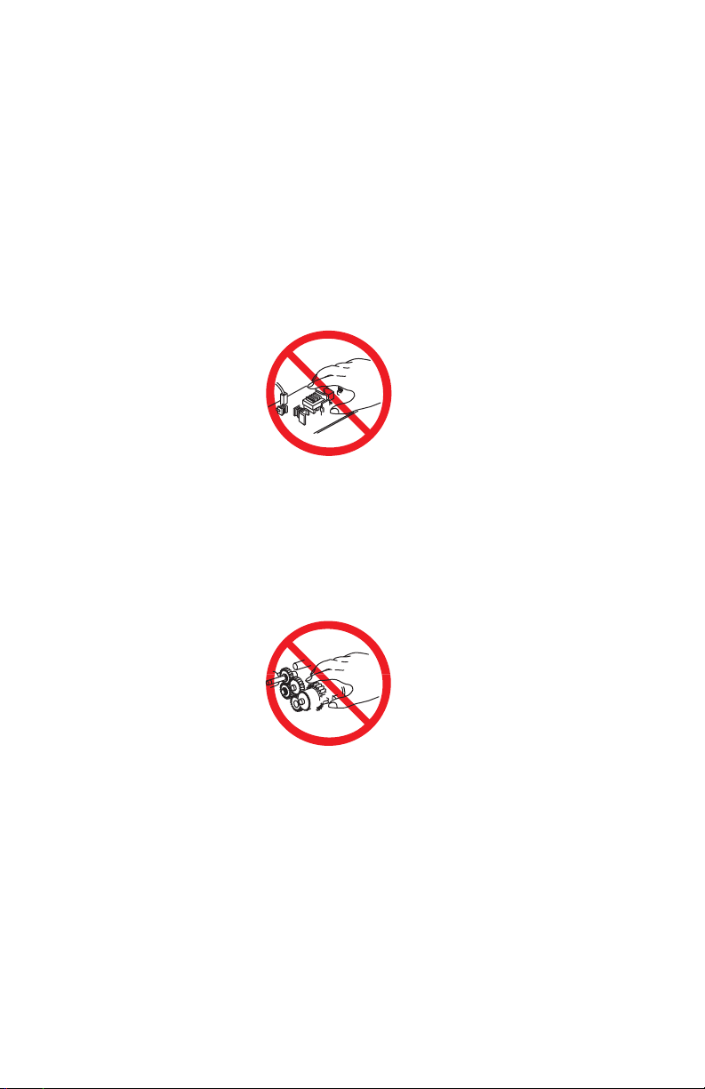
Warning: Do not touch any electrical component unless you are
instructed to do so by a service procedure.
S7300-02
Servicing Mechanical Components
Manually rotate drive assemblies to inspect drive gears.
Warning: Do not try to manually rotate or manually stop the drive
assemblies while any printer motor is running.
S7300-03
Servicing Fuser Components
This printer uses heat to fuse the toner image to a sheet of paper. The Fuser Assembly
is very hot. Turn the printer power OFF and wait at least 5 minutes for the Fuser to
cool before you attempt to service the Fuser Assembly or adjacent components.
viii Phaser 4400 Laser Printer Service Manual
Page 10

Regulatory Specifications
Federal Communications Commission Compliance
The equipment described in this manual generates and uses radio frequency energy. If
it is not installed properly in strict accordance with Xerox instructions, it may cause
interference with radio and television reception or may not function properly due to
interference from another device. However, there is no guarantee that interference
will not occur in a particular installation. If this equipment does cause harmful
interference to radio or television reception, which can be determined by turning the
equipment off and on, the user is encouraged to try to correct the interference by one
or more of the following measures:
■ Reorient or relocate the receiver (device being interfered with).
■ Increase the separation between the printer and the receiver.
■ Connect the printer into an outlet on a circuit different from that which the
receiver is connected.
■ Route the interface cables on the printer away from the receiver
■ Consult the dealer, Xerox service, or an experienced radio/television
technician for help.
Changes or modifications not expressly approved by Xerox can affect the emission
and immunity compliance and could void the user's authority to operate this product.
To ensure compliance, use shielded interface cables. A shielded parallel cable can be
purchased directly from Xerox at www.xerox.com/officeprinting/6200supplies
Xerox has tested this product to internationally accepted electromagnetic emission
and immunity standards. These standards are designed to mitigate interference caused
or received by this product in a normal office environment. This product is also
suitable for use in a residential environment based on the levels tested.
.
In the United States this product complies with the requirements of an unintentional
radiator in part 15 of the FCC rules. Operation is subject to the following two
conditions: (1) this device may not cause harmful interference; (2) this device must
accept any interference received, including interference that may cause undesired
operation.
This digital apparatus does not exceed the Class B limits for radio noise emissions
from digital apparatus set out in the Radio Interference Regulations of the Canadian
Department of Communications, ICES-003.
Le présent appareil numérique n'émet pas de bruits radioélectrique dépassant les
limits applicables aux appareils numériques de la classe B prescrites dans le
Réglement sur le brouillage radioélectrique édicté par le ministere des
Communications du Canada, NMB-003.
Declaration of Conformity
Xerox Corporation, declares, under our sole responsibility that the printer to which
this declaration relates, is in conformity with the following standards and other
normative documents:
Phaser 4400 Laser Printer Service Manual ix
Page 11

In the European Union
following the provisions of the Low Voltage Directive 73/23/EEC and its
amendments:
EN 60950 (IEC 950) “Safety of Information Technology Equipment including Electrical
Business Equipment”
following the provisions of the Electromagnetic Compatibility Directive 89/336/EEC
and its amendments:
EN55022:1998
(CISPR 22)
EN61000-3-2:1995
+A1:1998+A2:1998.
(IEC61000-3-2)
EN61000-3-3:1995
(IEC61000-3-3)
EN55024:1998
(CISPR 24)
CISPR 24 Immunity
Phenomena
Electrostatic Discharge IEC61000-4-2:1995 6kV Contact, 10kV Air
Radio-Frequency
Electromagnetic Field
(radiated)
Fast Burst Transients IEC61000-4-4:1995 5/50 Tr/Th ns, 5kHz Rep. Freq
Line Surge IEC61000-4-5:1995 Combination wave
Radio-Frequency
Electromagnetic Field
(Conducted)
Line voltage dips IEC61000-4-11:1994 >95% dip for ½ cycle @ 50 Hz
Line voltage drop-out IEC61000-4-11:1994 >95% dropout for 250 cycles @ 50 Hz
“Limits and Methods of measurement of radio interference
characteristics of Information Technology Equipment.” Class B.
“Part 3: Limits - Section 2: Limits for harmonic current emissions
(equipment input current less than or equal to 16A per phase).”
“Part 3: Limits - Section 3: Limitation of voltage fluctuations and
flicker in low-voltage supply systems for equipment with rated
current less than or equal to 16A.”
“Information technology equipment - Immunity characteristics Limits and methods of measurement. “
Basic Standard Test Specification
IEC61000-4-3:1995 80-1000 MHz, 3V/m, 80% AM @
1KHz
0.5kV on Signal Lines
1kV on AC Mains
2.0kV Common mode
2.0kV Differential mode
IEC61000-4-6:1996 0.15 - 80 MHz, 3V, 80% AM @ 1kHz
30% dip for 25 cycles @ 50 Hz
This product, if used properly in accordance with the user's instructions is neither
dangerous for the consumer nor for the environment. A signed copy of the
Declaration of Conformity for this product can be obtained from Xerox.
x Phaser 4400 Laser Printer Service Manual
Page 12

Safety Standards
Phaser 4400 satisfies the following safety standards:
Category Standard Satisfied
Laser Safety 100 V/120 V type is submitted to FDA 21 CFR
Ozone Density Does not exceed 0.02 ppm of ozone density TWA
Other standards 100 V/120 V type satisfies:
(Chapter 1, Subchapter J, Section 1010/1040).
220 V/240 V type is submitted to IEC 825 Class 1
Laser Product.
(Time Weight Average), measured according to ECMA
129 standard
UL 1950 3rd Edition, CSA C22.2 no. 950-M95 or
equivalent, NOM
200 V/220 V satisfies:
IEC 950 including amendments 1,2,3 and 4, CE
Directive 1, Nordic and other Agency Approval 2, CCIB
Notes:
1. When the controller is installed, the OEM customer
shall be responsible for the submittal of CE and CCIB.
2. The OEM customer shall be responsible for the
Nordic agency approvals including NEMKO, SEMKO,
SETI and DEMKO.
Phaser 4400 Laser Printer Service Manual xi
Page 13

xii Phaser 4400 Laser Printer Service Manual
Page 14

Contents
General Information 1-1
Section Contents. . . . . . . . . . . . . . . . . . . . . . . . . . . . . . . . . . . . 1-1
Phaser 4400 Laser Printer Overview . . . . . . . . . . . . . . . . . . . . 1-2
Parts of the Printer . . . . . . . . . . . . . . . . . . . . . . . . . . . . . . . . . . 1-4
Machine Orientation . . . . . . . . . . . . . . . . . . . . . . . . . . . . . . . . 1-12
Menu Map . . . . . . . . . . . . . . . . . . . . . . . . . . . . . . . . . . . . . . . . 1-13
Printer Specifications . . . . . . . . . . . . . . . . . . . . . . . . . . . . . . . 1-14
Error Messages and Codes 2-1
Section Contents. . . . . . . . . . . . . . . . . . . . . . . . . . . . . . . . . . . . 2-1
Introduction . . . . . . . . . . . . . . . . . . . . . . . . . . . . . . . . . . . . . . . . 2-1
Service Diagnostics. . . . . . . . . . . . . . . . . . . . . . . . . . . . . . . . . . 2-7
Printer Error Messages . . . . . . . . . . . . . . . . . . . . . . . . . . . . . . 2-11
Image Processor POST Error Codes . . . . . . . . . . . . . . . . . . . 2-58
Troubleshooting 3-1
Section Contents. . . . . . . . . . . . . . . . . . . . . . . . . . . . . . . . . . . . 3-1
Introduction . . . . . . . . . . . . . . . . . . . . . . . . . . . . . . . . . . . . . . . . 3-1
Measurements . . . . . . . . . . . . . . . . . . . . . . . . . . . . . . . . . . . . . 3-1
Troubleshooting Procedures. . . . . . . . . . . . . . . . . . . . . . . . . . . 3-2
Image-Quality Checkout Procedures . . . . . . . . . . . . . . . . . . . 3-41
Image-Quality Troubleshooting Procedures . . . . . . . . . . . . . . 3-53
Tests Prints, Adjustments, and NVRAM Reset 4-1
Section Contents. . . . . . . . . . . . . . . . . . . . . . . . . . . . . . . . . . . . 4-1
Service Test Prints . . . . . . . . . . . . . . . . . . . . . . . . . . . . . . . . . . 4-1
Adjustments . . . . . . . . . . . . . . . . . . . . . . . . . . . . . . . . . . . . . . . 4-5
Resetting NVRAM . . . . . . . . . . . . . . . . . . . . . . . . . . . . . . . . . . . 4-7
Phaser 4400 Laser Printer Service Manual xiii
Page 15

Cleaning and Maintenance 5-1
Service Preventive Maintenance Procedure . . . . . . . . . . . . . . . 5-1
FRU Disassembly 6-1
List of Procedures . . . . . . . . . . . . . . . . . . . . . . . . . . . . . . . . . . . 6-1
Covers and Trays . . . . . . . . . . . . . . . . . . . . . . . . . . . . . . . . . . . 6-6
Tray 1 . . . . . . . . . . . . . . . . . . . . . . . . . . . . . . . . . . . . . . . . . . . 6-18
Paper Feed (Tray 1) . . . . . . . . . . . . . . . . . . . . . . . . . . . . . . . . 6-28
Paper Feed (MPT). . . . . . . . . . . . . . . . . . . . . . . . . . . . . . . . . . 6-44
Paper Transportation. . . . . . . . . . . . . . . . . . . . . . . . . . . . . . . . 6-57
Exit Assembly and Fuser. . . . . . . . . . . . . . . . . . . . . . . . . . . . . 6-65
Xerographics . . . . . . . . . . . . . . . . . . . . . . . . . . . . . . . . . . . . . . 6-79
Main Drive . . . . . . . . . . . . . . . . . . . . . . . . . . . . . . . . . . . . . . . . 6-84
Electrical . . . . . . . . . . . . . . . . . . . . . . . . . . . . . . . . . . . . . . . . . 6-87
Stacker . . . . . . . . . . . . . . . . . . . . . . . . . . . . . . . . . . . . . . . . . 6-101
Optional Paper Feeder . . . . . . . . . . . . . . . . . . . . . . . . . . . . . 6-120
Duplex Unit . . . . . . . . . . . . . . . . . . . . . . . . . . . . . . . . . . . . . . 6-141
Envelope Feeder . . . . . . . . . . . . . . . . . . . . . . . . . . . . . . . . . . 6-157
Parts Lists 7-1
Parts List Index . . . . . . . . . . . . . . . . . . . . . . . . . . . . . . . . . . . . . 7-1
Using the Parts Lists . . . . . . . . . . . . . . . . . . . . . . . . . . . . . . . . . 7-1
Theory of Operation 8-1
Section Contents . . . . . . . . . . . . . . . . . . . . . . . . . . . . . . . . . . . . 8-1
Print Process Overview . . . . . . . . . . . . . . . . . . . . . . . . . . . . . . . 8-3
Print Process Description . . . . . . . . . . . . . . . . . . . . . . . . . . . . . 8-5
The Paper Path . . . . . . . . . . . . . . . . . . . . . . . . . . . . . . . . . . . . 8-11
Drive Flow . . . . . . . . . . . . . . . . . . . . . . . . . . . . . . . . . . . . . . . . 8-14
Engine Logic Board and Front Panel Functions . . . . . . . . . . . 8-22
Image Processor Board. . . . . . . . . . . . . . . . . . . . . . . . . . . . . . 8-22
Power Supplies . . . . . . . . . . . . . . . . . . . . . . . . . . . . . . . . . . . . 8-23
Interlocks . . . . . . . . . . . . . . . . . . . . . . . . . . . . . . . . . . . . . . . . . 8-24
xiv Phaser 4400 Laser Printer Service Manual
Page 16

Laser Control . . . . . . . . . . . . . . . . . . . . . . . . . . . . . . . . . . . . . 8-25
Fuser Control . . . . . . . . . . . . . . . . . . . . . . . . . . . . . . . . . . . . . 8-26
Erase Cycle. . . . . . . . . . . . . . . . . . . . . . . . . . . . . . . . . . . . . . . 8-28
Fan Control . . . . . . . . . . . . . . . . . . . . . . . . . . . . . . . . . . . . . . . 8-28
Duplex Printing . . . . . . . . . . . . . . . . . . . . . . . . . . . . . . . . . . . . 8-29
Envelope Feeder. . . . . . . . . . . . . . . . . . . . . . . . . . . . . . . . . . . 8-33
Stacker . . . . . . . . . . . . . . . . . . . . . . . . . . . . . . . . . . . . . . . . . . 8-37
Option Feeder Assembly. . . . . . . . . . . . . . . . . . . . . . . . . . . . . 8-42
Wiring Data 9-1
Section Contents. . . . . . . . . . . . . . . . . . . . . . . . . . . . . . . . . . . . 9-1
Introduction . . . . . . . . . . . . . . . . . . . . . . . . . . . . . . . . . . . . . . . . 9-2
Base Engine Wiring Data . . . . . . . . . . . . . . . . . . . . . . . . . . . . . 9-4
550-Sheet Feeder . . . . . . . . . . . . . . . . . . . . . . . . . . . . . . . . . . 9-22
Duplex Unit . . . . . . . . . . . . . . . . . . . . . . . . . . . . . . . . . . . . . . . 9-26
Stacker . . . . . . . . . . . . . . . . . . . . . . . . . . . . . . . . . . . . . . . . . . 9-31
Envelope Feeder. . . . . . . . . . . . . . . . . . . . . . . . . . . . . . . . . . . 9-37
Phaser 4400 Laser Printer Service Manual xv
Page 17

xvi Phaser 4400 Laser Printer Service Manual
Page 18

General Information
The Xerox Phaser™ 4400 Laser Printer Service Manual is the primary document
used for repairing, maintaining and troubleshooting.
To ensure complete understanding of the product, participation in Xerox Phaser 4400
Service Training is recommended.
Section Contents
Phaser 4400 Laser Printer Overview. . . . . . . . . . . . . . . . . . . . . . . . . . . . . . . .1-2
Configurations . . . . . . . . . . . . . . . . . . . . . . . . . . . . . . . . . . . . . . . . . . . . . . . . . 1-2
Printer Memory Configuration . . . . . . . . . . . . . . . . . . . . . . . . . . . . . . . . . . . . . 1-3
Monitoring Consumables . . . . . . . . . . . . . . . . . . . . . . . . . . . . . . . . . . . . . . . . . 1-3
Repackaging Information . . . . . . . . . . . . . . . . . . . . . . . . . . . . . . . . . . . . . . . . . 1-3
Parts of the Printer . . . . . . . . . . . . . . . . . . . . . . . . . . . . . . . . . . . . . . . . . . . . . .1-4
Base Configuration Components . . . . . . . . . . . . . . . . . . . . . . . . . . . . . . . . . . . 1-4
Internal Components . . . . . . . . . . . . . . . . . . . . . . . . . . . . . . . . . . . . . . . . . . . . 1-6
Printer Options . . . . . . . . . . . . . . . . . . . . . . . . . . . . . . . . . . . . . . . . . . . . . . . . . 1-6
Front Panel Configuration . . . . . . . . . . . . . . . . . . . . . . . . . . . . . . . . . . . . . . . . 1-8
Image Processor Board . . . . . . . . . . . . . . . . . . . . . . . . . . . . . . . . . . . . . . . . . 1-10
Machine Orientation . . . . . . . . . . . . . . . . . . . . . . . . . . . . . . . . . . . . . . . . . . . .1-12
Menu Map. . . . . . . . . . . . . . . . . . . . . . . . . . . . . . . . . . . . . . . . . . . . . . . . . . . . .1-13
Printer Specifications . . . . . . . . . . . . . . . . . . . . . . . . . . . . . . . . . . . . . . . . . . .1-14
Physical Specifications . . . . . . . . . . . . . . . . . . . . . . . . . . . . . . . . . . . . . . . . . . 1-14
Media and Tray Specifications . . . . . . . . . . . . . . . . . . . . . . . . . . . . . . . . . . . . 1-14
Functional Specifications . . . . . . . . . . . . . . . . . . . . . . . . . . . . . . . . . . . . . . . . 1-18
Electrical Specifications . . . . . . . . . . . . . . . . . . . . . . . . . . . . . . . . . . . . . . . . . 1-19
Environmental Specifications . . . . . . . . . . . . . . . . . . . . . . . . . . . . . . . . . . . . . 1-19
Phaser 4400 Laser Printer Service Manual 1-1
Page 19

Phaser 4400 Laser Printer Overview
The Phaser 4400 Laser Printer combines a monochrome print engine with an image
processor supporting PostScript 3 and PCL5e/6. The Phaser 4400 is a high
performance, 26 ppm desktop laser printer with a resolution up to 1200 x 1200 dpi.
Configurations
The Phaser 4400 is available in four configurations. A replaceable “Configuration
Upgrade Chip” holds configuration information that enables or disables built-in
features as described here.
Phaser 4400B The Phaser 4400B is the base configuration laser printer. The printer
comes standard with 32 Mbytes of memory, 600 x 600 dpi resolution, USB and
Parallel support, a built in Multi-Purpose Tray, and a 550-sheet universal paper tray.
Note: The Phaser 4400B reports 32 Mbytes of memory even though
Phaser 4400N The Phaser 4400N is the networking configuration. This
configuration includes all the features of the 4400B, but comes with 64 Mbytes of
memory, built-in 10/100 Ethernet networking capabilities, and a resolution up to 1200
x 1200 dpi.
Phaser 4400DT The Phaser 4400DT includes all the features of the 4400N but
comes standard with built in auto-duplexing, and one added 550-sheet feeder.
Phaser 4400DXThe Phaser 4400DX includes all the features of the 4400DT, along
with a 20-Gbyte hard drive and a Stacker with offset.
it has a 64-Mbyte DIMM installed. In order to get the full
64 Mbytes of memory to be reported as well as activate other
features, users need to upgrade to the N-configuration with a
Configuration Upgrade Kit, part number 098S04703.
Page Description Languages (PDL)
■ PCL5e/6
■ Adobe PostScript 3
■ PDF
Resident Fonts
■ 39 PostScript Roman fonts available on all models, plus an additional 97
Roman fonts available with the optional Hard Drive.
■ 81 PCL fonts (more fonts are available with the optional internal Hard
Drive.)
1-2 Phaser 4400 Laser Printer Service Manual
Page 20

Printer Memory Configuration
The printer features two slots which accept 32-, 64-, and 128-Mbyte SDRAM
DIMMs. All combinations except 32 Mbytes alone are allowed to a maximum of 256
Mbytes.
The Phaser 4400B reports 32 Mbytes of memory, even though it has a 64-Mbyte
DIMM installed. In order to get the full 64 Mbytes of memory to be reported as well
as activate other features, users must upgrade to the N-model with a Configuration
Upgrade Kit, part number 098S04703.
The Startup page and the Configuration pages list the amount of RAM installed in the
printer.
If the memory does not meet the following specifications, it is ignored by the printer.
■ PC133 DRAM Standard
■ 144-Pin SODIMM
■ Serial Presence Detect
■ 3.3 Volt
Monitoring Consumables
The status of printer consumables is available through the Supplies Info Menu.
Replaceable Items Print Life
Print Cartridge (rated at 5% image
coverage of letter-size paper)
Maintenance Kit (includes Fuser,
Transfer Roller, and nine rollers for Feed,
Retard, and Nudger Roller assemblies).
High-Capacity 15,000
Toner wt. 620 g (1.36 lbs.)
Standard-Capacity 10,000
Toner wt. 420 g. (.9 lbs.)
up to 200,000
Repackaging Information
If the printer must be returned to Xerox and the customer has not saved the shipping
box and all internal packaging, a repackaging kit is available for order from the local
Customer Support Center.
Repackaging Kit: part number 065-0606-00
Phaser 4400 Laser Printer Service Manual 1-3
Page 21
Parts of the Printer
The parts of the printer are covered here in three groups:
■ Base configuration components
■ Internal components
■ Printer options
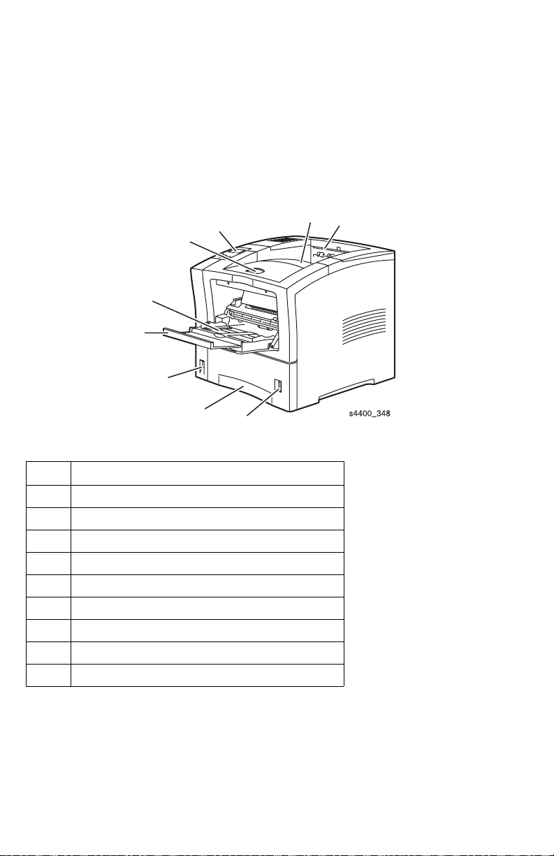
Base Configuration Components
3
4
5
6
7
2
1
8
Front view of base configuration
No. Description
1. Paper exit slot
2. Standard Output Tray
3. Front panel
4. Front cover (shown closed)
5. Multi-Purpose Tray (MPT)
6. Multi-Purpose Tray extension
7. Power switch
8. Tray 1
9. Paper level gauge
9
1-4 Phaser 4400 Laser Printer Service Manual
Page 22

1
2
3
4
5
6
Rear view of base configuration
No. Description
1. Option Cover
2. Rear cover release
3. Rear cover (shown closed)
4. Parallel connector
5. USB connector
6. Ethernet connector
7. Power cord receptacle
8. Left cover
9. Ventilation slots
9
7
8
Phaser 4400 Laser Printer Service Manual 1-5
Page 23
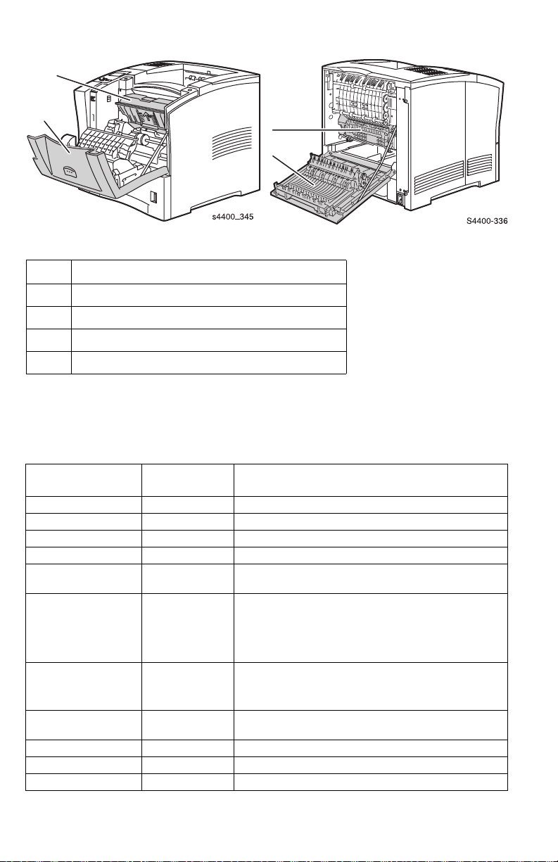
Internal Components
1
2
3
4
Front and rear views with covers open
No. Description
1. Print Cartridge
2. Front cover (shown open)
3. Fuser
4. Rear door (shown open)
Printer Options
The following customer-installed options are available for the Phaser 4400 printer.
Option Customer
Description
Order Number
32-Mbyte DIMM 97S02923 32-Mbyte Memory
64-Mbyte DIMM 97S02912 64-Mbyte Memory
128-Mbyte DIMM 97S02913 128-Mbyte Memory
16-Mbyte Flash DIMM 97S02914 16-Mbyte Flash ROM for storage of fonts, forms, etc.
4400 Network
Upgrade Kit
20+ Gbyte Hard Drive 97S02917 Adds hard disk capability to the printer:
550-Sheet Feeder 97S02878 Provides 550-sheet additional input capacity when
550-Sheet Paper Tray 109R00448 Used with the 550-Sheet Feeder. The Tray holds 550
Duplex Unit 97S02880 Provides duplex (two sided) printing capability.
Stacker 97S02881 Adds 500 sheet output capacity with offset capability.
Envelope Feeder 97S02879 Provides dedicated envelope feed.
98S04703 Configuration Upgrade Chip upgrades a Base printer
to a Network printer.
■ Stores fonts, forms, etc.
■ Enables collation, proof, secure and save jobs.
■ Provides user documentation, setup and care
videos, and printer drivers.
used in conjunction with the 550-sheet Paper Tray.
You can install one or two 550-Sheet Feeders.
sheets of paper.
1-6 Phaser 4400 Laser Printer Service Manual
Page 24
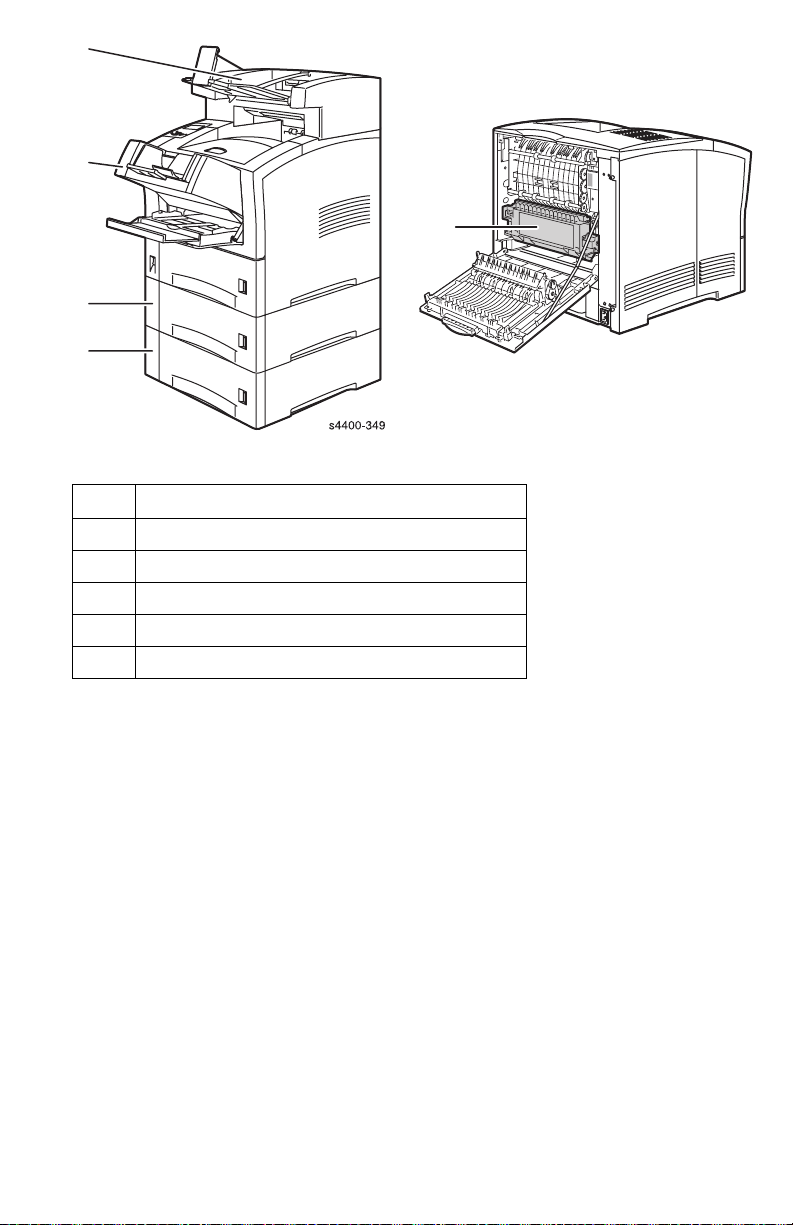
1
2
5
3
4
Printer options
No. Description
1. 500-Sheet Stacker
2. Envelope feeder
3. 550-sheet feeder with tray 2
4. 550-sheet feeder with tray 3
5. Automatic duplex unit
s4400-346
Phaser 4400 Laser Printer Service Manual 1-7
Page 25
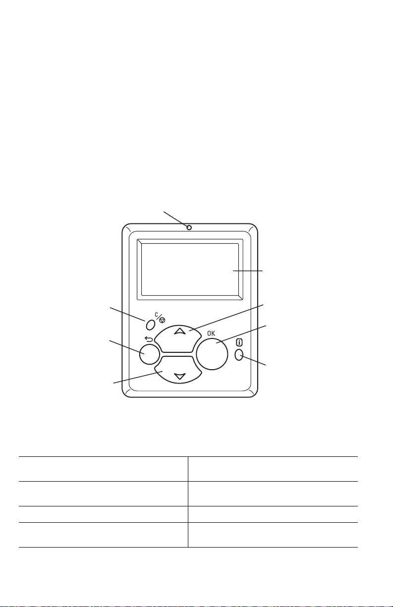
Front Panel Configuration
The Front Panel consists of one tricolor LED, a display window and six functional
keys. These keys navigate the menu system, perform functions and select modes of
operation for the printer.
The LED (light emitting diode) above the Graphics Display can be green, yellow or
red, and can be off, blinking or steady.
LED indications:
Green — Ready to Print
Flashing Green — Receiving, Processing Data or Printing
Flashing Yellow — Warning
Flashing Red — Error (blinks in unison with Image Processor Health LED)
1
2
3
5
7
4
8
6
s4400_006
Phaser 4400 Front Panel Configuration
Front Panel Key Descriptions
Status LED
1
Graphic front panel display
2
Cancel Key
3
Back Key
4
Up Arrow Key - scrolls up the menu
5
system
Down Arrow Key - scrolls down the menu
6
system
OK (select) Key
7
INFO Key - for additional explanation or
8
help
1-8 Phaser 4400 Laser Printer Service Manual
Page 26

Front Panel Shortcuts
Mode Press this selection at power-on
Skip execution of POST diagnostics OK
Print Service Menu Map INFO
Reset PostScript NVRAM BACK+OK
When “Password” appears, press UP +
DOWN keys within 2 seconds
Enter Service Diagnostics BACK+INFO
Phaser 4400 Laser Printer Service Manual 1-9
Page 27
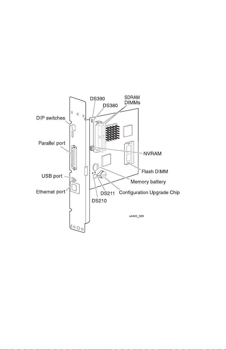
Image Processor Board
The following components must be transferred from the old board when installing a
new Image Processor Board in the printer:
■ SDRAM DIMMs (Slot 1 on the left, slot 2 on the right)
■ NVRAM
■ Configuration Upgrade Chip
■ Flash DIMM
See RRP 9.2 Image Processor Board on page 6-88 for information on replacing the
Image Processor Board.
Inside the printer on the Image Processor board are four LEDs shown in the figure.
DS210 illuminates when the e-net rate is set to 10 Mbits/sec (off indicates
100 Mbits/sec).
DS211 illuminates when a link is established.
DS380 is the HEALTH LED. The CPU flashes this LED to indicate that it is “alive”,
or in the case of a failure, the CPU flashes this LED (and the Front Panel LED, also)
with a code to help diagnose the problem.
DS390 is the CHECK STOP indicator, which illuminates when various fatal errors
occur in the CPU.
1-10 Phaser 4400 Laser Printer Service Manual
Page 28

Rear Panel Configuration Interfaces
■ IEEE 1284 parallel
■ Ethernet 10/100BaseTx
■ USB
On the Ethernet port, the green LED is a RECEIVE DATA indicator and the yellow
LED is a TRANSMIT DATA indicator.
Rear Panel DIP Switch Settings
Note: The DIP switch setting information presented here is meant
to provide a means of returning to as-shipped status in case
the switches have been inadvertently changed. Except in
extreme circumstances, the DIP switches should be left in the
Normal operating mode.
The DIP switches are defined as follows:
■ Switches 1-2 select the modes of operation, as follows:
DIP Switch Settings
Mode of Operation SW1 SW2 SW3 SW4
Normal (or Customer) Open Open Open Open
Manufacturing Open Closed Open Open
Developer (no POST) Closed Closed Open Open
Disaster Recovery (vxWorks only) Closed Open Open Open
■ Switch 3 selects whether the rear panel serial port presents PostScript or
vxWorks backchannel messages. OPEN presents PostScript; Closed presents
vxWorks.
■ Switch 4 is an IP board Reset switch (normally OPEN).
Processor Information
The processor used on the Image Processor board is a 266 MHz PowerPC processor.
Phaser 4400 Laser Printer Service Manual 1-11
Page 29
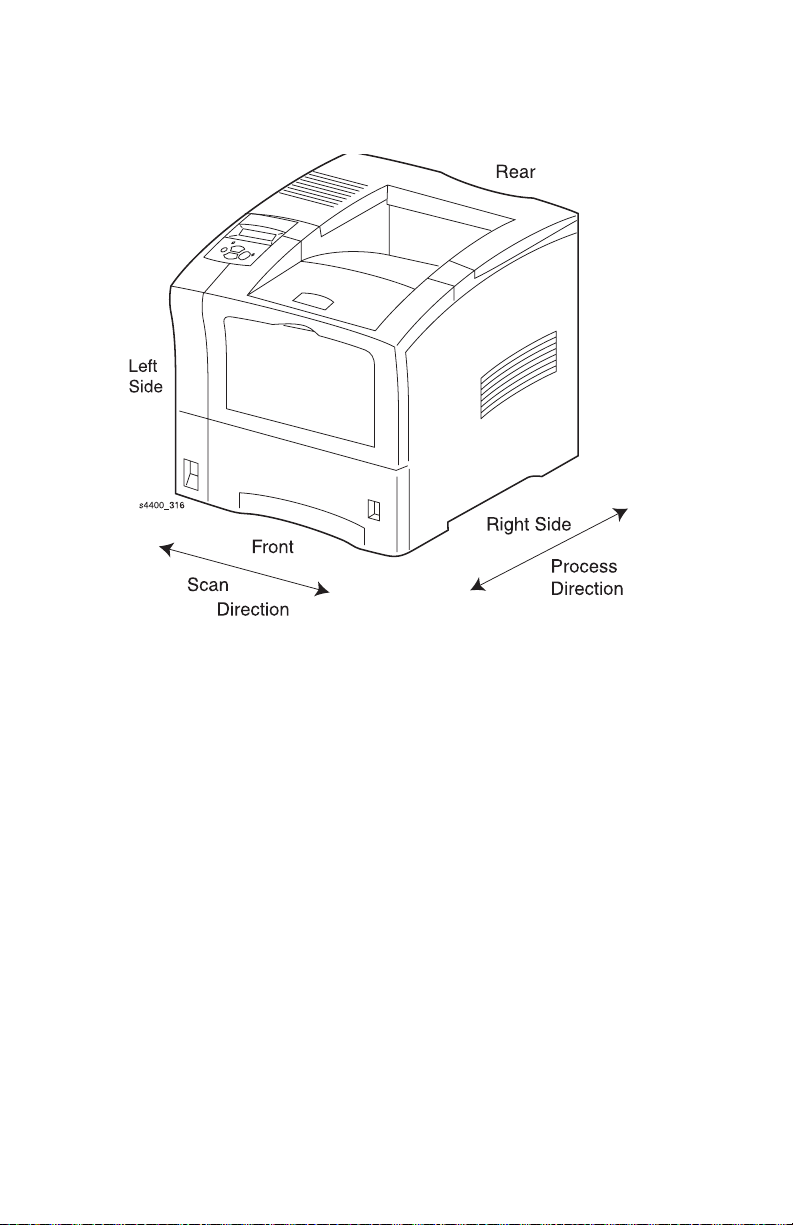
Machine Orientation
For servicing the Phaser 4400 Laser Printer, all references to machine orientation are
as illustrated below.
Machine Orientation
1-12 Phaser 4400 Laser Printer Service Manual
Page 30
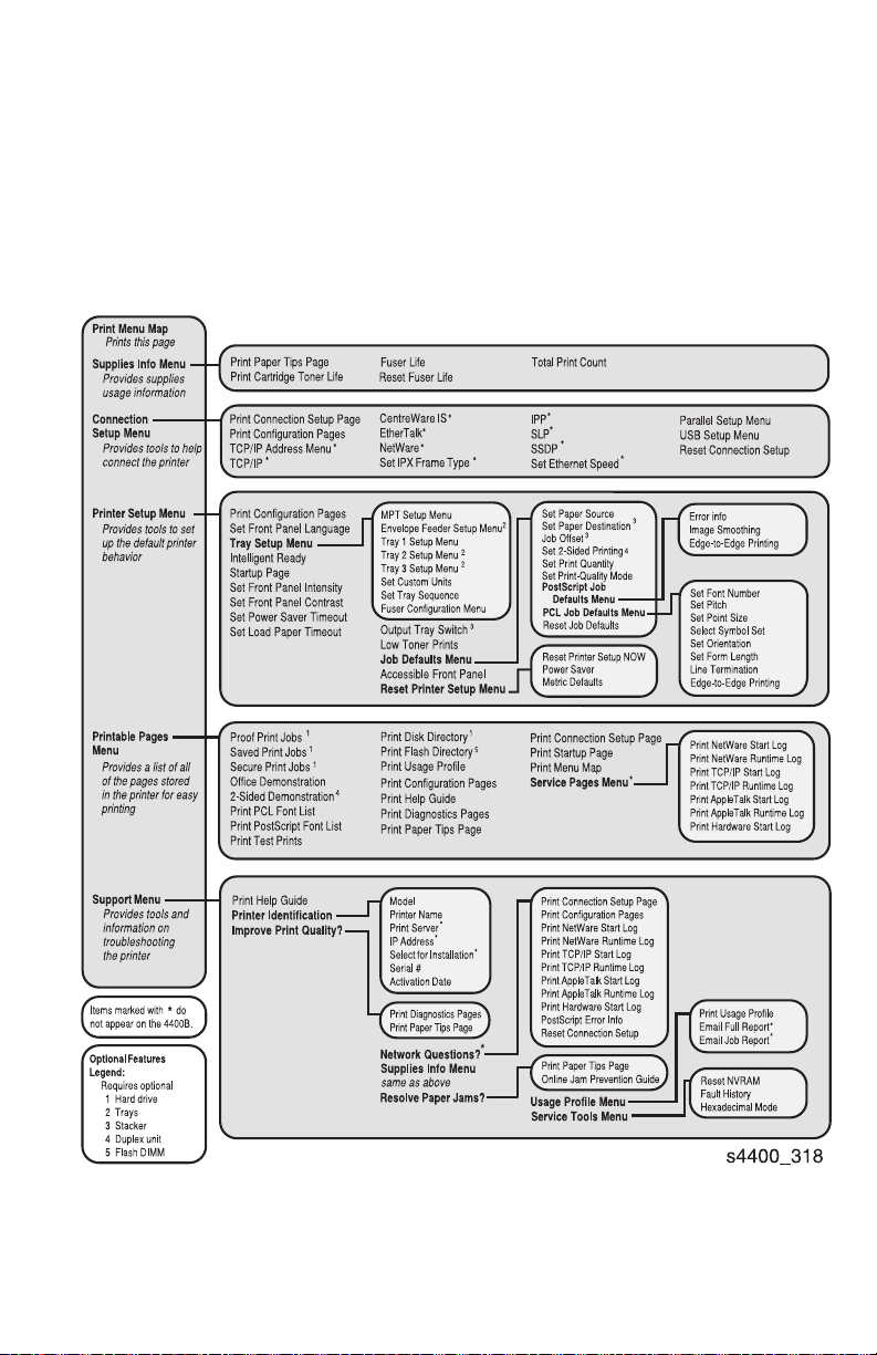
Menu Map
The menu map shown here lists the choices available when you select Menus, and is
printed when you select
of menus, items, and values found in the Menu Map is the order in which the menus,
items, and values are displayed when scrolling through the menu items.
Menus and items in this map marked with a numbered footnote do not appear on the
front panel display unless the associated option is installed in the printer. Items in this
map marked with an asterisk (*) do not appear on the base configuration 4400B.
Print Menu Map from the top level of Menus. The order
Phaser 4400 Laser Printer Service Manual 1-13
Page 31

Printer Specifications
Physical Specifications
Physical Dimensions - Printer
Dimensions Value
Size and weight (not
including the Print
Cartridge, Image
Processor Board or any
options)
Printer clearances
Clearances Value
Top (to closest
overhead object):
Left: Minimum 12” or 300 mm
Right: 300 mm (12 in.)
Front: Minimum 600 mm (24 in.)
Rear: Minimum 600 mm (24 in.)
Mounting surface
flatness:
Width: 422 mm x Depth 439 mm x Height 413 mm (16.5 in. x
17.25 in. x 16.25 in.)
Weight: 25 Kg (55 lbs.)
Packaged Weight: 32.7 kg (72 lbs.)
With Stacker 102 mm (4.0")
Without Stacker 292 mm (11.5")
Horizontal bias within 5° of level
Media and Tray Specifications
Refer to the “Paper Tips” pages shown beginning on page 1-15. You can print the
Paper Tips pages from the Front Panel by selecting
Menu | Print Paper Tips Page
.
The following table lists the total paper capacities available with the three paper deck
combinations:
Maximum Paper Stack Capacity
Combination MBF
(standard)
1 100 sheets 550 sheets — — 650 sheets
2 100 sheets 550 sheets 550 sheets — 1200 sheets
3 100 sheets 550 sheets 550 sheets 550 sheets 1750 sheets
Note: Paper stack capacity applies to baseline paper:
Xerox 4200/4024 20 lb. Letter and RX 80 A4 (3R91720).
1-14 Phaser 4400 Laser Printer Service Manual
1st deck
(standard)
Menus | Supplies Info
2nd deck
(option)
3rd deck
(option)
Tota l
Capacity
Page 32

The Paper Tips Pages shown here list the supported paper and paper sizes, and
provide the paper specifications for the printer.
Refer to the following tables to ensure the best print-quality and to avoid paper jams. For best results, use Xerox-branded paper as it is
guaranteed to produce excellent results on your Xerox Phaser
vary depending on vendor and type of paper used.
Note: If you change the type of paper or transparencies, you must specify the type on the front panel of the printer. For the Multi-Purpose Tray
or envelope feeder only: if you change the size of paper, also specify the size on the front panel.
TM
4400 Laser Printer. Print-quality and paper handling performance may
Supported paper and paper sizes
Input Output
Paper Type
550-Sheet Tray
Multi-Purpose
Tray
A4 (210 x 297 mm)
A5 (148 x 210 mm)
A6 (105 x 148 mm)
ISO B5 (176 x 250 mm)
(1) (1)
(1)
custom
(1)
custom
B5 JIS (182 x 257 mm)
Index Card (3 x 5 in.)
Statement (5.5 x 8.5 in.)
---
custom
(1)
Executive (7.25 x 10.5 in.)
Letter (8.5 x 11 in.)
US Folio (8.5 x 13 in.)
Legal (8.5 x 14 in.)
Envelopes
#10 Commercial (4.12 x 9.5 in.)
Monarch (3.87 x 7.5 in.)
DL (110 x 220 mm)
C5 (162 x 229 mm)
B5 (176 x 250 mm)
custom
custom
custom
custom
custom
(1)
(1)
(1)
(1)
(1)
Transparencies
A4 (210 x 297 mm)
Letter (8.5 x 11 in.)
(1)
(1)
Labels
A4 (210 x 297 mm)
Letter (8.5 x 11 in.)
(2)
Capacity
= Short-edge feed (1) Simplex (one-sided) printing only. (2) Maximum capacity at 75 g/m (20 lb.) paper stock. Capacity is reduced for heavier/thicker stock.
(1)
(1)
550 100 75 500 500
2
Envelope
Feeder
---
---
(1)
(1)
---
---
(1)
(1)
---
---
---
---
---
---
(1)
(1)
(1)
(1)
(1)
custom
(1)
(1)
(1)
(1)
---
---
---
---
Standard
Tray
(1)
500-Sheet
Stacker
---
(1)
(1)
(1)
(1)
(1)
s4400_351
Paper Tips Page 1 of 3
Phaser 4400 Laser Printer Service Manual 1-15
Page 33

Custom paper sizes
550-Sheet Tray
(one-sided)
Simplex
Width
Length
Duplex
Width
Length
98 - 216 mm 76 - 216 mm 98 - 178 mm 76 - 216 mm 98 - 216 mm
3.87 - 8.5 in. 3.0 - 8.5 in. 3.87 - 7.0 in. 3.0 - 8.5 in. 3.87 - 8.5 in.
148 - 356 mm 127 - 356 mm
5.83 - 14.0 in. 5.0 - 14.0 in. 5.83 - 10.0 in. 5.0 - 14.0 in. 5.83 - 14.0 in.
(two-sided)
182 - 216 mm
7.16 - 8.5 in.
257 - 356 mm
10.12 - 14.0 in.
Input Output
Multi-Purpose Tray
182 - 216 mm
7.16 - 8.5 in.
257 - 356 mm
10.12 - 14.0 in.
Envelope Feeder Standard Tray 500-Sheet Stacker
148 - 254 mm
---
---
127 - 356 mm 148 - 356 mm
Same as Input
Same as Input
Paper weights
The Phaser 4400 Laser Printer supports paper weights as follows:
• 16 - 130 lbs. (60 - 216 g/m ) simplex/one-sided
• 16 - 28 lbs. (60 - 105 g/m ) duplex/two-sided
Plain Paper: (60 - 120 g/m ) (16 - 32 lb.)
Card Stock: (120 - 216 g/m ) (32 - 130 lb.)
TM
2
2
2
2
Paper tips
• If excessive jams occur, flip the paper in the tray or install fresh paper from a newly opened ream.
• Transparencies should be fanned prior to loading.
• Other size envelopes may be printed as custom paper sizes.
• Use only paper envelopes. Do not use envelopes with windows or metal clasps.
• Label media should be fanned prior to loading.
• Do not print to label stock once a label has been removed.
s4400_352
Paper Tips Page 2 of 3
1-16 Phaser 4400 Laser Printer Service Manual
Page 34

Ordering supplies
See
www.xerox.com/officeprinting/4400supplies
Xerox Branded Paper
Item Paper Size Part Number
Plain Paper
Xerox Premier 80 A4 (210 x 297 mm) 3R91720
Xerox Premier 80 A5 (148 x 210 mm) 3R91832
Xerox 4024 DP statement Statement (5.5 x 8.5 in.) 3R2072
Xerox 4024 DP Letter (8.5 x 11 in.) 3R721
Xerox 4024 DP folio Folio (8.5 x 13 in.) 3R725
Xerox 4024 DP legal Legal (8.5 x 14 in.) 3R727
Transparencies
Xerox 3M Type L transparencies A4 (210 x 297 mm) 3R91334
Xerox Clear transparencies Letter (8.5 x 11 in.) 3R4446
Labels
Xerox A4 24-up label A4 (210 x 297 mm) 3R96178
Xerox Multi-purpose 30-up label Letter (8.5 x 11 in.) 3R12051
for information on ordering supplies.
Replaceable Items
Item Part Number
Standard-Capacity Print Cartridge 113R00627
High-Capacity Print Cartridge 113R00628
Maintenance Kit
Contains: a Fuser Cartridge,
1 Transfer Roll, and 9 Feed Rollers.
s4400_353
108R00497
108R00498
for 110 V (60 Hz)
for 220 V (50 Hz)
Paper Tips Page 3 of 3
Phaser 4400 Laser Printer Service Manual 1-17
Page 35

Functional Specifications
Characteristic Specification
Printing process Recording System - Electro-photographic system (roller charging,
Resolution /
Addressability
Operating Modes Ready Mode: Ready to receive data.
Continuous Operating
Printing Speed
Fuser Configuration
Temperature
First Print Out
(Engine speed only)
Warm-up time From a cold start (22° C / 71.6° F ambient temperature) to READY
single component magnetic toner development)
Exposure System - Infrared Laser Diode Beam Scanning
Class 1 Laser Product
Class 3B Laser, rated at 5 mW output @ 780 nm
Fusing System - Heat and pressure
600/1200 dots per inch (dpi), switchable at full engine speed.
Power Saver Mode: entered after a user-specified period of Print
Engine inactivity since completion of the last print to minimize
energy consumption.
Paper Size Fuser Setting Duplex
Low Medium High Extra High (ipm)
Letter SEF 18 26 22 8 19
A4 SEF 18 25 22 8 18
Legal 14” SEF 18 21.5 18 7.5 16
Legal 13” SEF 18 21.5 18 7.5 16
Executive 18 26 22 8 19
B5 (JIS) SEF 18 26 22 8 19
Low - Medium setting High - Extra High setting
Range: 194-209°C/ Range: 197-212°C/
381-408°F 387-414°F
Tray 1 (t sec) Tray 2 (sec) Tray 3 (sec) MPT (sec)
Paper Size Simp Dup Simp Dup Simp Dup Simp Dup
Letter 7.5 13.8/ 8.3 14.6/ 9.2 15.5/ 7.7 14.0/
14.6 15.4 16.3 14.8
A4 7.6 14.0/ 8.4 14.8/ 9.3 15.7/ 7.8 15.9/
15.4 16.2 17.1 17.3
TO PRINT within 70 seconds.
1-18 Phaser 4400 Laser Printer Service Manual
Page 36

Electrical Specifications
Characteristic Specification
Power supply 120 VAC (98–140 VAC) 50/60 Hz (47 Hz – 63 Hz)
220/240 VAC (198–264 VAC) 50/60 Hz (47 Hz – 63 Hz)
Power consumption Maximum - 600 Watts
Printing - 525 Watts/hour or 1792 Btus/hour
Standby - 110 Watts/hour or 375 Btus/hour
Power Saver - 20 Watts/hour or 68 Btus/hour
Note: No electrical power is supplied to the Fuser assembly in
Power Saver Mode.
Environmental Specifications
Characteristic Specification
Operating environment 5–35° C / 41–95° F @ 15% to 85% Relative Humidity (operating)
0 - 3100 meter (10171 ft.) above sea level
Storage environment
with a packed Print
Cartridge
Storage environment
without a packed Print
Cartridge
Heat Emission Maximum - 2730 BTU; Average - 1603; 102 (sleep mode)
Acoustic Noise (MPT
closed; options are
Duplex Unit, two
additional feeders,
Envelope Feeder,
Stacker)
Dust Emission No more than 0.075 mg/m3 concentration.
Ozone Emission No more than 0.02 mg/m3 concentration, measured in accordance
Normal condition:12 months maximum at 0–35° C/32–95° F
@ 15–80% Relative Humidity with no condensation present
Severe condition: 1 month maximum at -20° to 0° C / -4° to 32° F or
35° to 40° C / 95 to104° F
@ 5–15 or 80–95% Relative Humidity with no condensation present
Normal condition: 12 months maximum at -20 to -50° C / -4 to -58° F
@ 5-85% Relative Humidity with no condensation present
Severe condition: 48 hours maximum at 50–60° C / 122–140 ° F
@ 85-95% Relative Humidity with no condensation present
Standby: 4.9 B (35.0 dB(A))
Power Saver: 0 dB above background noise
Printing (without options): 6.8 B (52.0 dB(A))
Printing (with options): 7.1 B (55.5 dB(A))
with BAM Standard.
Phaser 4400 Laser Printer Service Manual 1-19
Page 37

1-20 Phaser 4400 Laser Printer Service Manual
Page 38

Error Messages and Codes
Section Contents
Introduction . . . . . . . . . . . . . . . . . . . . . . . . . . . . . . . . . . . . . . . . . . . . . . . . . . . .2-1
Service Flowchart . . . . . . . . . . . . . . . . . . . . . . . . . . . . . . . . . . . . . . . . . . . . . . . 2-2
Service Technician Cautionary Statements . . . . . . . . . . . . . . . . . . . . . . . . . . . 2-3
Procedures . . . . . . . . . . . . . . . . . . . . . . . . . . . . . . . . . . . . . . . . . . . . . . . . . . . . 2-3
Voltage Measurements. . . . . . . . . . . . . . . . . . . . . . . . . . . . . . . . . . . . . . . . . . . 2-4
Using Fault History . . . . . . . . . . . . . . . . . . . . . . . . . . . . . . . . . . . . . . . . . . . . . . 2-5
Service Diagnostics . . . . . . . . . . . . . . . . . . . . . . . . . . . . . . . . . . . . . . . . . . . . .2-7
Entering Service Diagnostics . . . . . . . . . . . . . . . . . . . . . . . . . . . . . . . . . . . . . . 2-7
Service Diagnostics Menu Map . . . . . . . . . . . . . . . . . . . . . . . . . . . . . . . . . . . . 2-8
Using the Front Panel with Service Diagnostics . . . . . . . . . . . . . . . . . . . . . . . . 2-9
Engine Test Print . . . . . . . . . . . . . . . . . . . . . . . . . . . . . . . . . . . . . . . . . . . . . . 2-10
Engine NVRAM Default Settings . . . . . . . . . . . . . . . . . . . . . . . . . . . . . . . . . . 2-10
Printer Error Messages. . . . . . . . . . . . . . . . . . . . . . . . . . . . . . . . . . . . . . . . . .2-11
Index of Errors . . . . . . . . . . . . . . . . . . . . . . . . . . . . . . . . . . . . . . . . . . . . . . . . 2-11
Error Message Summaries . . . . . . . . . . . . . . . . . . . . . . . . . . . . . . . . . . . . . . . 2-12
Image Processor POST Error Codes. . . . . . . . . . . . . . . . . . . . . . . . . . . . . . .2-58
Fault Reporting Devices . . . . . . . . . . . . . . . . . . . . . . . . . . . . . . . . . . . . . . . . . 2-58
Introduction
This section covers troubleshooting procedures for the Phaser 4400 Laser Printer’s
front panel error messages. Only jams and fatal errors will produce an associated
numeric code. Error messages and codes are usually specific, making it important that
service personnel and users record errors exactly when reporting problems with the
printer.
Any error code associated with an error message or jam can be viewed by pressing the
INFO key. Jam error are displayed at the beginning of the info menu, while engine
errors are display at the end.
Some procedures require running Service Diagnostics tests to verify a specific printer
assembly is operating correctly. Refer to Service Diagnostics on page 2-7.
To troubleshoot problems not associated with a front panel error message or code
such as ac power, or problems related to print-quality, refer to the section
Troubleshooting on page 3-1.
Phaser 4400 Laser Printer Service Manual 2-1
Page 39

Service Flowchart
The Service Flowchart outlines one possible approach to troubleshooting and repair
of the printer. The Service Flowchart is an overview of the path a service technician
could
take, using this technical manual, to service the printer and options.
If you choose not to use the Service Flowchart, it is recommended that you start at the
appropriate troubleshooting table and proceed from there.
Step 1: Identify the Problem:
1. Verify the reported problem does exist.
2. Check for any error codes and write them down.
3. Print Test Prints.
4. Make note of any print-quality problems in the Test Prints.
5. Make note of any mechanical or electrical abnormalities present.
6. Make note of any unusual noise or smell coming from the printer.
7. Print a Usage Profile Report, if the printer is able to print.
8. View the fault history under the Service Tools Menu
9. Verify the AC input power supply is within proper specifications.
Step 2: Inspect and Clean the Printer:
1. Switch OFF printer power.
2. Disconnect the AC power cord from the wall outlet.
3. Verify the power cord is free from damage or short circuit and is connected properly.
4. Remove the Print Cartridge and protect it from light.
5. Inspect the printer interior and remove any foreign matter such as paper clips,
staples, pieces of paper, dust or toner.
6. Clean the printer interior with a lint-free cloth, dampened slightly with cold water and
mild detergent.
■ Do not use solvents or chemical cleaners to clean the printer interior.
■ Do not use any type of oil or lubricant on printer parts.
■ Use only an approved toner vacuum.
7. Clean all rubber rollers with a lint-free cloth, dampened slightly with cold water and
mild detergent.
8. Inspect the interior of the printer for damaged wires, loose connections, toner
leakage, and damaged or obviously worn parts.
9. If a Print Cartridge appears obviously damaged, replace with a new one.
Step 3: Find the Cause of the Problem:
1. Use the Print Engine Error Messages table (page 2-11) or POST Error Code table
(page 2-58) to find the cause of the problem.
2. Use Diagnostics to check printer and optional components.
3. Use the Wiring Diagrams and Plug/Jack Locator to locate test points.
4. Take voltage readings at various test points as instructed in the appropriate
troubleshooting procedure.
5. Use the Engine Logic Board Test Print on page 3-49, to isolate print capability
problems between the print engine the Image Processor Board.
Step 4: Correct the Problem:
1. Use the Parts List to locate a part number
2. Use the Removal and Replacement Procedures to replace the part.
Step 5: Final Checkout:
1. Test the printer to be sure you have corrected the initial problem and there are no
additional problems present.
2-2 Phaser 4400 Laser Printer Service Manual
Page 40

Service Technician Cautionary Statements
■ Always turn off the printer and remove the AC power cord, unless instructed
to do otherwise in a procedure. This is particularly important when checking
continuity between wiring.
■ If the printer is kept ON, never touch the conductive parts.
■ Wear an electrostatic discharge wrist strap to help prevent damage to the
sensitive electronics on the printer circuit boards.
■ Wait at least 5 minutes after you have switched OFF the printer power for
the Fuser to cool before you work on or around the Fuser.
■ If checking a specific part with the covers removed and the interlocks, safety
and power switches ON, laser beams may be irradiated from the Laser Unit
causing a health hazard. Observe proper precautions at all times.
■ When using service diagnostics to turn motors, drives and/or gears, never
touch or interrupt the moving parts as damage to the printer will result.
Procedures
Using the Troubleshooting Procedures
1. Each Step in a Troubleshooting Procedure instructs you to perform a certain action
or procedure. The steps are to be followed sequentially in the order given until the
problem is fixed or resolved.
2. The Actions and Questions box contains additional information and/or additional
procedures you must follow to isolate the problem.
3. When a procedure instructs you test a component using service diagnostics, see
Service Diagnostics on page 2-7 for the detailed steps and functions for testing
parts of the printer.
4. The action is followed by a question. If your response to the question is “Ye s” ,
then follow the instructions for a “Ye s ” reply. If your response to the question is
“No”, then follow the instructions for a “No” reply.
5. Troubleshooting Procedures may ask you to take voltage readings or test for
continuity at certain test points within the printer. For detailed diagrams, refer to
the section Wiring Data on page 9-1 for complete information on test point
locations and signal names.
6. Troubleshooting Procedures often ask you to replace a printer component. The
section FRU Disassembly on page 6-1 provides detailed steps for removing and
replacing all major parts of the printer. The section Parts Lists on page 7-1 details
the location, quantity and part number for all spared parts of the printer.
Phaser 4400 Laser Printer Service Manual 2-3
Page 41

General Notes on Troubleshooting
1. Unless indicated otherwise, the instruction “switch ON printer main power” means
for you to switch ON printer power and let the printer proceed through POST.
2. When instructed to take voltage, continuity or resistance readings on wiring
harness, proceed as follows: check P/J 232–1 to P/J 210–5 by placing the red probe
(+) of your meter on pin 1 of P/J 232, and place the black probe (–) of your meter
on pin 5 of P/J 210.
3. When you are instructed to take voltage readings between “P/J 232 P/J 210”
(without specified pin numbers), check all pins. Refer to the section Wiring Data
on page 9-1 for the location of all wiring harnesses and pins.
4. When you are instructed to take a voltage reading, the black probe (–) is generally
connected to a pin that is either RTN (Return) or SG (Signal Ground). You can
substitute any RTN pin or test point in the printer, and you can use FG (frame
ground) in place of any SG pin or test point.
5. Unless a troubleshooting procedure instructs otherwise; before measuring voltages
make sure the printer is switched ON, the Imaging Unit and the paper trays are in
place, and the interlock switches are actuated.
6. All voltage values given in the troubleshooting procedures are approximate values.
The main purpose of voltage readings is to determine whether or not a component
is receiving the correct voltage value from the power supply and if gating (a
voltage drop) occurs during component actuation. Gating signals may be nothing
more than a pulse, resulting in a momentary drop in voltage that may be difficult or
impossible to read on the average multi-meter.
7. When a Troubleshooting Procedure instructs you to replace a non-spared
component and that component is part of a parent assembly, you should replace the
entire parent assembly.
Voltage Measurements
Power and signal grounds are connected to frame ground. You can perform all circuit
troubleshooting using the metal frame (chassis) as the grounding point. If you need
more information to locate connectors or test points, refer to Wiring Data on page 9-1.
Unless otherwise specified, the following voltage tolerances are used within this
section.
Voltage Measurements
Stated Measured Stated Measured
+3.3 VDC +3.0 to 3.6 VDC +24.0 VDC +21.6 to +26.4 VDC
+5.0 VDC +4.8 to +5.2 VDC 0.0 VDC Less than +0.5 VDC
2-4 Phaser 4400 Laser Printer Service Manual
Page 42

Using Fault History
The printer keeps a record of engine errors and jams. You can access Fault History for
either engine errors or jams in one of three ways:
■ View the Fault History at the Front Panel.
■ Print the printer’s Usage Profile.
■ View or print the Usage Profile from the printer’s web page, if the printer is
connected to a network.
The errors are presented as a series of one- or two-digit numeric codes. Use the tables
in “Interpreting Fault History” to decipher the codes.
When an error first occurs, record the error message and code, then cycle power to the
printer to see if the error recurs.
Accessing Fault History
1. View the printer’s fault history on the front panel.
a. Enter Menus, then select Support Menu | Service Tools
Menu | Fault History
b. Select
Engine Errors or Jam Errors to display the errors.
2. Print (if possible) the Usage Profile from the printer’s front panel Support
Menu
. Fault history information for Engine Errors and Jams is detailed in this
report log.
3. If the printer is connected to a network and has a TCP/IP address, view the
printer’s web page using a web browser.
a. Open a web browser.
b. Enter the printer’s IP address as the URL.
c. Select the “Jobs” tab and click the Usage Profile link. You can then
click a link to view or to print the Usage Profile.
.
Phaser 4400 Laser Printer Service Manual 2-5
Page 43

Interpreting Fault History Error Codes
The following tables provide a cross-reference of the numeric fault history codes to
the Diagnostic Message and code found in Printer Error Messages on page 2-11.
These numeric codes are displayed on the Front Panel for both Engine Errors and
Jams; in the Usage Profile, the numeric codes are used only in the Engine Error Log
(Item 262).
Fault History Codes for Engine Errors
Fault
History
Code
0 Fan Failure (U5) 6 Tray 2/3 Failure (E11)
1 Fuser Failure (U4) 7 Tray 1 Failure (C3)
2 Motor Failure (U1) 8 Tray 2 Failure (C3)
3 IOT NVM Failure (U6) 9 Tray 3 Failure (C3)
4 Stacker Failure (E9) 10 Tray 2 Failure (E11)
5 Laser failure (U2) — —
Error Fault
History
Code
Error
Fault History Codes for Jams
Fault
History
Code
1 E7-1 12 E2-12
2 E7-2 13 E2-03
3 E7-3 14 E2-13
4 E4-0 15 E2-0E
Jam Code Fault
History
Code
Jam Code
5 E4-2 16 E2-1E
6 E4-3 17 E6-1
7 E2-0M 18 E6-2
8 E2-1M 19 PSE-1
9 E2-01 20 E3-1
10 E2-11 21 E3-2
11 E2-02 22 E7-0
2-6 Phaser 4400 Laser Printer Service Manual
Page 44

Service Diagnostics
The printer’s Service Diagnostics provide the ability to:
■ Print the Service Diagnostics Menu Map.
■ Check the current print engine status.
■ Start the Engine Test Print after selecting the print quantity, the source tray,
output tray, and simplex or duplex printing.
■ Test the functionality of printer motors and fans, solenoids, and clutches.
■ Test some portions of drive trains by engaging combinations of motors and
clutches or solenoids.
■ Test the functionality of sensors, switches, and options by manually toggling
each sensor or installing an option.
■ Perform NVRAM adjustments essential to the performance of the printer.
■ Check eight different print engine components.
■ Reset the PS NVRAM locations to factory defaults (see Resetting NVRAM
on page 4-7).
Entering Service Diagnostics
To enter Service Diagnostics:
While turning on power, press and hold Back + Info until the message “Entering
Service Diagnostics” appears on the display, then release the keys. The Service
Diagnostics Menu appears.
The Service Diagnostic menu has the following selections:
General Status — Provides current print engine status.
Engine Test Print — Starts the test print.
Motors/Fans Tests — Tests the functionality of the printer Motors/Fan.
Main Motor + Clutches/Sol Tests — Tests the functionality of the main
motor plus clutches or Solenoid at the same time.
Sensor Tests — Tests the functionality of sensors, switches, or the presence of
options by manually toggling each sensor or installing an option. Some of the sensor
tests require cheating the front and/or rear door interlocks.
Note: The Service Diagnostics Sensor Tests do not include a check
of the Tray Stack Height Sensor. Refer to the Stack Height
Sensor Checkout on page 3-23.
Solenoid Tests — Tests the functionality of printer solenoids.
Clutch Tests — Tests the functionality of printer clutches.
Engine NVRAM Adjustments — Perform NVRAM adjustments essential to
the performance of the printer.
Phaser 4400 Laser Printer Service Manual 2-7
Page 45

Component Checks — Tests print engine component functions.
NVRAM Access — Lets you reset the PS NVRAM locations to factory defaults.
Exit — Reboots the Printer out of Diagnostics.
Service Diagnostics Menu Map
The Service Diagnostics Menu Map lists the tests available for testing print engine
parts and functions while diagnosing printer problems. When you enter Service
Diagnostics, the menu items shown in bold type appear on the front panel. When you
select one of these items, the list of individual tests appear.
Print Service Menu Map:
General Status:
Engine ROM Version
Engine Print Counter
Engine Configuration
Print Resolution
Read Fuser Temperature
Read Fuser Set Temperature
Engine Test Print: Starts the test print.
Print Test pattern
Input tray
Output tray
Duplex
Print Quantity
Motors/Fan Test:
Duplex Motor High
Duplex Motor Low
Exit Motor Forward
Exit Motor Reverse High
Exit Motor Reverse Low
Main Motor
Fan Motor High Speed
Laser Scan Motor
Stacker Motor
Stacker Offset Motor
Main Motor + Clutch/Sol Tests: * Runs main drive motor with each
individual clutch and MPT solenoid.
Sensor Tests:
manually toggling each sensor or installing an option.
Front Cover Switch
Rear Cover Switch
Paper Tray Size Read (display paper size, for trays)
Print Cartridge Switch
Toner Sensor
Registration Sensor
Exit Sensor (Fuser)
Duplex Sensor
Stacker Sensor
Stacker Full Sensor
Output Tray Full Sensor (Printer)
Tray 1 Low Paper Sensor
Tray 2 L
Tray 3 Low Paper Sensor
Tray 1 No Paper Sensor
Tray 2 No Paper Sensor
Tray 3 No Paper Sensor
MPT No Paper Sensor
Envelope Feeder No Paper Sensor
Envelope Feeder Presence
Duplex Unit Presence
Stacker Unit Presence
Provides current print engine status.
Test the functionality for motors/fan.
Tests the functionality of sensors/switches/options by
ow Paper Sensor
Prints this page
Solenoid Tests:
*MPT Solenoid
Stacker Direction Solenoid
Clutch tests:
*Registration Clutch
*Tray 1 Feed Clutch
*Tray 2 Feed Clutch
*Tray 3 Feed Clutch
*Tray 1 Turn Roll Clutch
*Tray 2 Turn Roll Clutch
*Tray 3 Turn Roll Clutch
*Envelope Feeder Clutch
Engine NVRAM Adjustments:
the performance of the printer.
Laser Power Setting
MPT Paper Size Adjustment
Envelope Paper Size Adjustment
Tray 1 Process Direction
Tray 2 Process Direction
Tray 3 Process Direction
Envelope Feeder Process Direction
MPT Process Direction
Tray 1 Scan Direction
Tray 2 Scan Direction
Tray 3 Scan Direction
Envelope Feeder Scan Direction
MPT Scan Direction
Duplex Process Direction
Duplex Scan Direction
Component Checks:
Laser Diode
Detack Saw Output
Transfer Roll +
Transfer Roll ñ
Developer Bias AC
Developer Bias DC
Charge Roll AC
Charge Roll DC
NVRAM Access: This menu lets you reset the PS NVRAM locations to
factory defaults.
PostScript NVRAM Reset
Exit:
For Service Use Only:
The Service menu functions are to be used by Xerox service personnel
and authorized service providers. The p
improper use of the built-in service tests.
Test the functionality of printer solenoids
Test the functionality of printer clutches.
Reboots Printer out of Diagnostics.
Perform NVRAM adjustments essential to
rinter can be damaged by
2-8 Phaser 4400 Laser Printer Service Manual
Page 46

Using the Front Panel with Service Diagnostics
The keys on the Front Panel provide the user interface for Service Diagnostics. The
keys and their functions are shown in Front Panel Configuration on page 1-8. After
you enter Service Diagnostics, the Up and Down keys allow you to move or scroll the
highlight up and down through a menu. When you have highlighted the item you
want to select, press OK to enter the selection.
When you are selecting a page quantity in the Engine Test Print menu use the
OK key to move the highlight to the right. then use the Up or Down key to change the
value of the selected digit. when you have entered the desired quantity, use the Back
key to enter the selection.
Note: If you moved past the digit you want to change, keep pressing
the OK key until the highlight wraps to the desired digit.
In most of the Service Diagnostics menus, use the Back key to exit a menu to the
level just above. In most cases, scrolling to the end of a menu and selecting Exit takes
you back to the Service Diagnostics Main Menu.
When you select Read Fuser Temperature from the General Status
menu, the temperature is presented in hex values. The following table lists the
temperatures that correspond to the hex values displayed.
Fuser Temperature Cross Reference Table
Hex value Tem p e ra t u re (°C / °F) Hex value Te m pe r a ture ( °C / °F)
EE 0°C / 32°F CA 140°C / 284F
FE 10°C / 50°F C6 145°C / 293°F
FD 20°C / 68°F C1 150°C / 302°F
FC 30°C / 86°F BD 155°C / 311°F
FB 40°C / 104°F B8 160°C / 320°F
F9 50°C / 122°F B3 165°C / 329°F
F7 60°C / 140°F AE 170°C / 338°F
F4 70°C / 158°F A9 175°C / 347°F
F0 80°C / 176°F A4 180°C / 356°F
EC 90°C / 194°F 99 190°C / 374°F
E7 100°C / 212°F 8F 200°C / 392°F
E1 110°C / 230°F 85 210°C / 410°F
DA 120°C / 248°F 7C 220°C / 428°F
D3 130°C / 266°F 72 230°C / 446°F
Phaser 4400 Laser Printer Service Manual 2-9
Page 47

Engine Test Print
The Engine Test Print test pattern (shown on page 4-4) is stored in the Engine Logic
Board and is accessible through Service Diagnostics. You can use the Engine Test
Print to identify, repair, and validate the operability of printer xerographics and paper
handling from all paper sources, options, and output destinations. When you select
Engine Test Print from the main Service Diagnostics menu, the following selections
are available:
Print Test Pattern — Starts the print
Input Tray — Allows you to select the paper source
Output Tray — Allows you to select the test print destination
Duplex — Turns duplexing on or off if the Duplex Unit is installed
Print Quantity — Allows you to select the number of test prints to run
Error and Jam Recovery
If the printer encounters a problem while printing the Engine Test Print, it halts
printing and displays an error message on the Front Panel. Refer to the Diagnostic
Messages in the Print Engine Error Messages table that follows. (The Diagnostic
Messages also appear as secondary headings in the Troubleshooting Procedures.)
Printing resumes after the problem has been fixed.
Engine NVRAM Default Settings
The following table lists the defaults for each of the Engine NVRAM Adjustments
except the paper size adjustments, which have no default settings.
NVRAM Default Table
Engine NVRAM
Adjustment
Laser Power 10 0 - 15 Tray 2 Scan Direction 3 0 - 8
Tray 1 Process
Direction
Tray 2 Process
Direction
Tray 3 Process
Direction
Envelope Process
Direction
MPT Process
Direction
Tray 1 Scan
Direction
Default
Value
8 0 - 15 Tray 3 Scan Direction 2 0 - 8
8 0 - 15 Envelope Scan Direction 4 0 - 8
8 0 - 15 MPT Scan Direction 6 0 - 8
8 0 - 15 Duplex Process
8 0 - 15 Duplex Scan Direction 4 0 - 8
4 0 - 8
Range Engine NVRAM
Adjustments
Direction
Default
Value
8 0 - 15
Range
2-10 Phaser 4400 Laser Printer Service Manual
Page 48

Printer Error Messages
Index of Errors
Front Panel Message Page
Jam Errors
Jam at Tray [#]. Open Tray [#] and Front Cover. Code: Jam E2-## 2-18
Jam at Envelope Feeder; Remove Feeder and Open Front Cover.
Code: Jam E2-#E
Jam at MPT; Open Front Cover to Clear. Code: Jam E2-0M
Code: Jam E2-1M
Jam at Front; Open Front Cover to Clear. Code: Jam E3-# 2-23
Jam At Exit; Open Rear Cover To Clear. Code: Jam E4-0
Code: Jam E4-2
Code: Jam E4-3
Jam at Stacker; Open Both Rear Covers to Clear. Code: Jam E6-# 2-27
Jam at Front/Rear; Open Front/Rear Cover to Clear. Code: Jam E7-1
Code: Jam E7-2
Code: Jam E7-3
Paper Size Jam; Check Size and Open Rear Cover to Clear. (PSE-1)
Code: Jam PSE-1
Door and Cover Errors
Close Front Cover/Close Rear Cover. 2-31
Consumable Errors
Install or Reseat Print Cartridge. 2-33
Replace Print Cartridge. 2-34
Toner is Low. 2-35
Maintenance Kit is Near End of Life. 2-36
Printer Option Errors
Install or Reseat the Duplex Unit. Code: E9-1 2-36
Stacker Failure. Code: E9-2 2-37
Install or Reseat the Envelope Feeder. Code: E9-E 2-37
Tray and Media Errors
Standard Output Tray is Full. Unload Paper. 2-38
Tray [#] Failure. Open and Close Tray [#]. C3-[#]E 2-43
Tray [#] Paper is Low. 2-39
Tray 2 (or Tray 3) Paper is Low. 2-40
Load MPT with [paper size] [paper type]. 2-51
No Paper in Tray [#]. 2-41
Media Mismatch Errors
Load Tray [#] with [paper size] [paper type]. 2-42
Front Panel Fatal Error Messages and Codes
Tray 2 or 3 Failure. Code: E11 2-52
Main Motor Failure. Code: U1 2-45
Laser Unit Failure. Code: U2 2-48
Fuser Failure. Code: U4 2-49
2-21
2-22
2-25
2-29
2-30
Phaser 4400 Laser Printer Service Manual 2-11
Page 49

Index of Errors (cont'd.)
Front Panel Message Page
Fan Failure; Power Off Now. Code: U5 2-49
Engine Logic Board NVRAM Failure. Code: U6 2-50
Image Processor POST Error Codes 2-58
Error Message Summaries
Note: The messages listed in the “Diagnostic Message” column
appear only in Service Diagnostics while printing Engine
Test Prints. The code numbers in these messages also
appear as part of the Help information displayed when you
press i.
Front Panel
Message
Jam At Tray [#];
Open Tray [#]
and Front Cover
to Clear.
Press i.
Jam At
Envelope
Feeder;
Remove Feeder
and Open Front
Cover to Clear.
Press i.
Jam At MPT;
Open Front
Cover To Clear.
Press i.
Diagnostic
Error Description Troubleshooting
Message
E2-01: Feed Jam
E2-02
E2-03
E2-11: Feed Jam
E2-12
E2-13
E2-0E: Feed Jam Paper arrives at
E2-1E: Feed Jam Paper does not
E2-0M: Feed Jam Paper arrives at
E2-1M: Feed Jam Paper does not
Paper arrives at
Registration Sensor
too early.
Paper does not
arrive at Registration
Sensor position
within the specified
time.
Registration Sensor
too early.
arrive at Registration
Sensor position
within the specified
time.
Registration Sensor
too early.
arrive at REG
Sensor position
within the specified
time.
Procedure
Open Tray [#].
Open Front Cover.
Clear Paper Path.
Go to Jam at Tray [#]. Open
Tray [#] and Front Cover.
on page 2-18.
Remove Envelope Feeder.
Open Front Cover.
Clear Paper Path.
Go to Jam at Envelope
Feeder; Remove Feeder
and Open Front Cover. on
page 2-21.
Open Front Cover and
remove paper.
Go to Jam at MPT; Open
Front Cover to Clear. on
page 2-22.
2-12 Phaser 4400 Laser Printer Service Manual
Page 50

Error Message Summaries (cont'd.)
Note: The messages listed in the “Diagnostic Message” column
appear only in Service Diagnostics while printing Engine
Test Prints. The code numbers in these messages also
appear as part of the Help information displayed when you
press i.
Front Panel
Message
Jam at Front;
Open Front
Cover to Clear.
Press i.
Jam At Exit;
Open Rear
Cover To Clear.
Press i.
Jam At Stacker;
Open Both Rear
Covers to Clear.
Press i.
Diagnostic
Error Description Troubleshooting
Message
E3-1: Registration
Jam
E3-2: Registration
Jam
E4-0: Exit Jam Paper leaves Exit
E4-2: Exit Jam 1. Paper late off Exit
E4-3: Exit Jam Custom Paper late
E6-1: Stacker Jam 1. Paper late to
E6-2: Stacker Jam 1. Paper late off
Paper Late to Fuser
sensor after arrival at
Registration Sensor.
Exit Sensor did not
actuate within time
after the Registration
clutch is actuated.
1. Registration
Sensor did not
deactuate within time
after actuation of
Registration sensor.
2. Registration
Sensor is actuated at
power-on.
Sensor early.
Sensor.
2. Exit Sensor on at
power-on.
off Exit Sensor,
exceeding the
specified time from
Registration Sensor.
Stacker Sensor.
Stacker Sensor.
2. Stacker Sensor on
at power-on.
Procedure
Open Front Cover.
Remove Print Cartridge.
Clear Paper Path.
Go to Jam at Front; Open
Front Cover to Clear. on
page 2-23.
Open Rear Cover.
Clear Paper Path.
Go to Jam At Exit; Open
Rear Cover To Clear. on
page 2-25.
Open Rear Cover.
Clear Paper Path.
Change Paper Setting in
Custom Mode to correct
size.
Go to Jam At Exit; Open
Rear Cover To Clear. on
page 2-25.
Open Stacker Rear Door.
Clear Paper Path.
Open Printer Rear Cover.
Clear Paper Path.
Go to Jam at Stacker; Open
Both Rear Covers to Clear.
on page 2-27.
Phaser 4400 Laser Printer Service Manual 2-13
Page 51

Error Message Summaries (cont'd.)
Note: The messages listed in the “Diagnostic Message” column
appear only in Service Diagnostics while printing Engine
Test Prints. The code numbers in these messages also
appear as part of the Help information displayed when you
press i.
Front Panel
Message
Jam At Front;
Open Front
Cover To Clear
Press i.
Jam At Rear;
Open Rear
Cover To Clear.
Press i.
Tray [#] Failure.
Open and Close
Tray [#].
Press i.
No (Load)
Paper In
Envelope
Feeder
Press i.
Load MPT MPT Paper Empty MPT is out of paper. Load paper into MPT.
Stacker Is Full,
Unload Paper.
Press i.
Standard Output
Tray is Full,
Unload Paper.
Press i.
Diagnostic
Error Description Troubleshooting
Message
E7-0: Duplex Jam Paper arrives at
E7-1: Duplex Jam Paper late to Duplex
E7-2: Duplex Jam 1. Paper late off
E7-3: Duplex Jam Paper late to
C3-#E Tray [#] Not In ■ Tray [#] is not
Envelope Feeder
Empty
Stacker Output Tray
Full
Output Tray Full Top Tray is declared
Registration Sensor
early from Duplex
Sensor.
Sensor.
Duplex Sensor.
2. Duplex Sensor on
at power-up.
Registration Sensor
from Duplex Sensor.
detected
■ Tray motor failure
■ Harness problem
■ Stack height sensor
failure
Envelope Feeder is
out of paper.
Several prints are
delivered to the top
tray after the Stacker
Full Stack Sensor is
actuated.
full when several
prints are delivered
to the top tray after
the Full Stack Sensor
is actuated.
Procedure
Open front cover.
Remove print cartridge.
Clear paper path.
Go to Jam at Front/Rear;
Open Front/Rear Cover to
Clear. on page 2-29.
Open Rear Cover.
Remove Duplex Unit.
Clear paper path.
Go to Jam at Front/Rear;
Open Front/Rear Cover to
Clear. on page 2-29.
Inspect and repair Tray [#].
Tray [#] Failure. Open and
Close Tray [#]. on
page 2-43.
Load Paper into Envelope
Feeder.
Go to Load Envelope
Feeder with [paper size]
[paper type]. on page 2-55.
Go to Load MPT with
[paper size] [paper type]. on
page 2-51.
Empty Stacker Tray.
Go to Stacker is Full,
Unload Paper. on
page 2-54.
Empty Top Tray.
Go to Standard Output Tray
is Full. Unload Paper. on
page 2-38.
2-14 Phaser 4400 Laser Printer Service Manual
Page 52

Error Message Summaries (cont'd.)
Note: The messages listed in the “Diagnostic Message” column
appear only in Service Diagnostics while printing Engine
Test Prints. The code numbers in these messages also
appear as part of the Help information displayed when you
press i.
Front Panel
Message
No Paper In
Tray [#]
Press i.
Load Tray [#]
with [paper size]
[paper type].
Close Front
Cover
Close Rear
Cover.
Press i.
Install or Reseat
The Duplex
Unit.
Press i.
Stacker Failure.
Press i.
Install or Reseat
the Envelope
Feeder
Press i.
Tray 2 or 3
Failure
Press i.
or
Tray 2 Failure
Press i.
Diagnostic
Error Description Troubleshooting
Message
Tray [#] Empty Tray [#] is out of
PSE-1: Paper Size
Error
Close Front
Cover/Close Rear
Cover
E9-1: Duplex Unit
Fail.
E9-2: Stacker Unit
Fail
E9-E: Envelope
Feeder Fail/Reinstall
E11: Tray 2/3 Fail Either Tray 2 or Tray
paper.
Paper Size Error. Load correct size paper in
1. Front cover
interlock is open.
2. Rear cover
interlock is open.
Duplex module
removed while power
is on.
Stacker removed
while power is on.
Envelope feeder
module removed
while power-on.
3 was disconnected
after power-on.
Procedure
Load paper into Tray [#].
Go to No Paper in Tray [#].
on page 2-41.
tray.
Go to Load Tray [#] with
[paper size] [paper type]. on
page 2-42
Close Front Cover.
Close Rear Cover.
Go to Close Front
Cover/Close Rear Cover.
on page 2-31.
Reinstall Duplex Module.
Go to Install or Reseat the
Duplex Unit. on page 2-36.
Reinstall Stacker.
Go to Stacker Failure. on
page 2-37.
Reinstall Envelope Feeder.
Go to Install or Reseat the
Envelope Feeder. on
page 2-37.
Reinstall Feeder 2/3.
Go to Tray 2 or 3 Failure.
on page 2-52.
Phaser 4400 Laser Printer Service Manual 2-15
Page 53

Error Message Summaries (cont'd.)
Note: The messages listed in the “Diagnostic Message” column
appear only in Service Diagnostics while printing Engine
Test Prints. The code numbers in these messages also
appear as part of the Help information displayed when you
press i.
Front Panel
Message
Paper Size
Jam; Check
Size and Open
Rear Cover To
Clear.
Press i.
Install Or
Reseat Print
Cartridge
Press i.
Toner Is Low.
Press i.
Main Motor
Failure
Press i.
Laser Unit
Failure
Press i.
Diagnostic
Error Description Troubleshooting
Message
PSE-1: Paper Size
Error
J3 Missing Print
Cartridge.
J5 Toner Low. Toner Low is
U1 Motor Fail/Power
Off
U2 Laser Fail/Power
Off
There is a conflict
between the size of
the paper, which is
detected by the Size
Switches, and the
length of paper the
printer detects by the
length of time the
Registration Sensor
is actuated.
1. Print Cartridge is
not installed.
2. The installed Print
Cartridge is not the
correct one.
detected after 10
prints while Toner
Sensor is on.
Main Motor speed is
less than specified
RPM after 1.3
seconds.
1.Transmitting /BD
signal is longer than
specified value for 10
sec. + t1.
2. The laser power
does not reach the
specified value.
3. Laser signal
intervals become
longer than the Fail
time interval after
Laser warm-up is
completed.
Procedure
Correct the mismatch.
Open Rear Cover.
Go to Paper Size Jam;
Check Size and Open Rear
Cover to Clear. (PSE-1) on
page 2-30.
Install the Print Cartridge,
or replace with the correct
Print Cartridge.
Go to Install or Reseat Print
Cartridge. on page 2-33.
Go to Toner is Low. on
page 2-35.
Power Off and On.
Go to Main Motor Failure.
on page 2-45.
Power Off and On.
Go to Laser Unit Failure. on
page 2-48.
2-16 Phaser 4400 Laser Printer Service Manual
Page 54

Error Message Summaries (cont'd.)
Note: The messages listed in the “Diagnostic Message” column
appear only in Service Diagnostics while printing Engine
Test Prints. The code numbers in these messages also
appear as part of the Help information displayed when you
press i.
Front Panel
Message
Fuser Failure
Press i.
Fan Failure
Power Off Now
Press i.
Engine Logic
Board NVRAM
Failure.
Press i.
Diagnostic
Message
U4 Fuser Fail/Power
Off
U5 Fan Fail/Power
Off
U6 NVM Fail/Power
Off
Error Description Troubleshooting
Procedure
■ Low temperature
trouble/Power off
(Fuser temperature
drops below the set
temperature after the
Fuser warm-up is
complete).
■ Warm-up
fail/Power off (Fuser
warm-up does not
complete within 110
seconds).
■ STS Disconnection
fail/Power off
(Thermistor circuit is
detected to be open).
■ High Temperature
trouble/Power off
(Fuser temperature
rises above the set
temperature).
■ Continuous heat
on/Power off (Heat
rod is on for 10
seconds when the
Main Drive Motor is
stopped, after the
Fuser warm-up is
completed).
Main Fan has failed. Check the Main Fan.
1. Read error
detected during
power-on.
2. Write Error
detected.
Go to Fuser Failure. on
page 2-49.
Power Off and On.
Go to Fan Failure; Power
Off Now. on page 2-49.
Power Off and On.
Go to Engine Logic Board
NVRAM Failure. on
page 2-50).
Phaser 4400 Laser Printer Service Manual 2-17
Page 55

Jam at Tray [#]. Open Tray [#] and Front Cover.
(E2-##: Feed Jam)
E2-0#: Paper arrives early to the Registration Sensor or is on the sensor at power-on.
E2-1#: Paper arrives late to the Registration Sensor.
Paper Jam/Misfeed Troubleshooting Procedure
Step Actions and Questions Yes No
1 Check the paper in all trays. Check for curled,
damaged, or damp paper and for paper that is out of
specification.
Is the paper in good condition and does it meet
specification?
2 Check all paper paths for contamination, paper, or
other obstructions.
Are all paper paths clean and free of
obstructions?
3 1. Enter Service Diagnostics and select Test Print.
2. Run five prints from every paper tray.
Does the problem appear when printing from
Tray 2 or 3?
4 1. Remove Tray 1 from the printer.
2. Check the Nudger Roller, Feed Roller, and Retard
Roller for contamination and wear.
Are all rolls clean and in good condition?
5 1. Reinsert Tray 1 into the printer.
2. From the rear of the printer, watch the Tray 1 Bottom
Plate.
Is the Bottom Plate raised fully and evenly?
6 From the rear of the printer, watch the paper feed as
you print a test print from Tray 1.
Do the Nudger Roller and Feed Roller rotate?
7
Is paper fed from the tray to the Turn Roller
Assembly?
Go to step 2. Replace with
fresh dry
paper that is
within specifications.
Go to step 3. Remove con-
tamination or
obstructions.
Go to step 9. Go to step 4.
Go to step 5. Clean or
replace the
Nudger, Feed
or Retard
Roller as
necessary
(RRP 3.8 on
page 6-36/
RRP 2.1 on
page 6-18).
Go to step 6. Go to Tray
Motor
Assembly
Checkout on
page 3-26.
Go to step 7. Go to Tray 1
Feed Clutch
on page 3-29.
Go to step 8. Replace the
Retard,
Nudger, and
Feed Rollers
(RRP 2.1 on
page 6-18 and
RRP 3.8 on
page 6-36).
2-18 Phaser 4400 Laser Printer Service Manual
Page 56

Paper Jam/Misfeed Troubleshooting Procedure (cont'd.)
Step Actions and Questions Yes No
8
Does the Turn Roller Assembly move the paper
to the Registration Sensor?
9 1. Remove Tray 1.
2. Check the paper chute at the front of the tray (the
chute guides paper from Tray 2 to the Tray 1 turn
rollers). Check for contamination, paper, or other
obstructions.
Go to
Registration
Sensor on
page 3-20.
Go to step
10.
Is the chute clean and free of obstructions?
10
Do the jams occur when feeding from Tray 3.
11 1. Remove Tray 2 and place the tray in Feeder 1.
2. Place Tray 1 in Feeder 2.
3. Enter Service Diagnostics and select Test Print.
4. Run 20 to 25 test prints from Tray 2.
Did all prints complete successfully?
12 1. Remove the tray currently in Feeder 2.
2. Check the Nudger and Feed Rollers in Feeder 2 for
contamination and wear.
Go to step
14.
The paper
tray currently
in Feeder 1
appears to
be defective.
Go to step
18.
Go to step
13.
Are the Feed Rollers clean and in good
condition?
13 Check the Tray 2 Turn Roller Assembly for
obstructions, contamination, or wear.
Are the Turn Rolls clean and in good condition?
14 Remove Tray 1 and Tray 2. Check the paper chute at
the front of both trays (the chute guides paper from
Tray 3 to the Tray 2 turn rolls and from Tray 2 to the
Tray 1 turn rollers). Check for contamination, paper, or
other obstructions.
Replace the
Feeder PWB
(RRP 11.9 on
page 6-128).
If the problem persists,
replace the
Size PWB
(RRP 11.19
on
page 6-139),
then the
Engine Logic
Board (RRP
9.3 on
page 6-89).
Go to step
15.
Is the chute clean and free of obstructions?
Go to Turn
Roller Clutch
Assembly on
page 3-28.
Remove
obstructions
and clean
chute.
Replace paper
tray if necessary (PL 2.1
on page 7-6).
Go to step 11.
Go to step 12.
Replace the
Feed Rollers
(RRP 11.11 on
page 6-130).
Remove the
obstruction;
clean, or
replace the
Turn Roller
Assembly
(RRP 11.8 on
page 6-127).
Remove
obstructions
and clean
chute.
Replace paper
tray if necessary (PL 2.1
on page 7-6).
Phaser 4400 Laser Printer Service Manual 2-19
Page 57

Paper Jam/Misfeed Troubleshooting Procedure (cont'd.)
Step Actions and Questions Yes No
15 1. Replace Tray 2.
2. Remove Tray 3 and place the tray in Feeder 1.
3. Place Tray 1 in Feeder 3.
4. Enter Service Diagnostics and select Test Print.
5. Run 20 to 25 test prints from tray 3.
Did all prints complete successfully?
16 1. Remove the tray currently in Feeder 3.
2. Check the Nudger and Feed Rolls in Feeder 3 for
contamination and wear.
The paper
tray currently in
Feeder 1
appears to
be defective.
Go to step
19.
Go to step
17.
Are the Feed Rolls clean and in good condition?
17 Check the Tray 3 Turn Roller Assembly for
obstructions, contamination, or wear.
Go to step
20.
Are the Turn Rolls clean and in good condition?
18 Perform Tray Motor Assembly Checkout on page 3-26
to check the tray motor.
Does it operate correctly?
19 Perform Tray Motor Assembly Checkout on page 3-26
to check the tray motor.
Does it operate correctly?
20 Replace the Feeder PWB (RRP 11.9 on page 6-128). If
the problem persists, replace in this order:
■ Size PWB (RRP 11.19 on page 6-139)
■ Engine Logic Board (RRP 9.3 on page 6-89)
Check the
paper tray for
contamination, obstructions, broken
or deformed
parts.
Replace the
paper tray if
necessary
(PL 2.1 on
page 7-6).
Check the
paper tray for
contamination, obstructions, broken
or deformed
parts.
Replace the
paper tray if
necessary
(PL 2.1 on
page 7-6).
Go to step 16.
Replace the
Feed Rolls
(RRP 11.11 on
page 6-130).
Remove the
obstruction,
clean, or
replace the
Turn Roller
Assembly
(RRP 11.8 on
page 6-127).
Follow the
repair advice
in the
checkout
procedure.
Follow the
repair advice
in the
checkout
procedure.
2-20 Phaser 4400 Laser Printer Service Manual
Page 58

Jam at Envelope Feeder; Remove Feeder and Open
Front Cover.
(E2-#E: Feed Jam)
E2-0E: Paper arrives at Registration Sensor too early.
E2-1E: Paper does not arrive at Registration Sensor position within a specified time.
Envelope Feeder Jam Troubleshooting Procedure
Step Actions and Questions Ye s No
1 1. Remove all envelopes.
2. Check the Envelope Feeder and Printer for
contamination, paper scraps, or other obstructions.
Is the printer and Envelope Feeder clean and
free of obstructions?
2 Check the Feed Belts. Check for dirt or contamination
on the top side and the under side of the belt.
Are both sides of the belt clean?
3 1. Enter Service Diagnostics and select Clutch Tests.
2. Scroll to Envelope Feeder and press OK.
Can you hear the clutch energize?
4 1. Press Back.
2. Scroll to Main Motor+Clutch/Sol Tests and press OK.
3. Scroll to Motor+Envelope Feeder.
4. Press OK and watch the Feed Belts and Feed
Rollers.
Do all the Feed Belts and Feed Rollers rotate?
5 Ensure the Envelope Feeder is installed properly and is
contacting the printer drive gear.
Is the Envelope Feeder installed correctly?
6 Remove the Envelope Feeder and check the feeder
drive gears.
Are all gears in good condition and operating
properly?
Go to step 2. Clean feeder
Go to step 3. Replace the
Go to step 4. Go to
Go to step 7. Go to step 5.
Go to step 6. Reinstall the
Replace the
Envelope
Feed Clutch
(RRP 13.12
on
page 6-168).
If the problem persists,
Replace the
Envelope
Feeder PWB
(RRP 13.3
on
page 6-159).
and remove
all
obstructions.
Feed Belts
(RRP 13.17
on
page 6-176).
Envelope
Feed Clutch
on
page 3-38.
Envelope
Feeder
correctly.
Replace the
gears as
necessary
(PL 12.2 on
page 7-32).
Phaser 4400 Laser Printer Service Manual 2-21
Page 59

Envelope Feeder Jam Troubleshooting Procedure (cont'd.)
Step Actions and Questions Yes No
7 Perform Registration Sensor on page 3-20 to check the
Registration Sensor.
Is the Registration Sensor operating correctly?
Replace the
Engine Logic
Board (RRP
9.3 on
page 6-89).
Jam at MPT; Open Front Cover to Clear.
(E2-#M: Feed Jam)
E2-0M: Paper arrives at REG sensor early.
E2-1M: Paper arrives at REG sensor late.
Feed Jam Procedure
Step Actions and Questions Yes No
1 1. Switch the printer power OFF.
2. Open the Front Cover.
3. Check the MPT Chute for contamination or
obstructions.
Is the MPT free of contamination, paper, or other
obstructions?
2 Check the MPT Feed Roller for contamination and
wear.
Is the feed roller clean and in good condition?
3 1. Enter Service Diagnostics and select Solenoid Tests.
2. Scroll to MPT and press OK.
Can you hear the solenoid energize?
4 1. Open the Front Cover and cheat the Front Cover
Interlock.
2. From the Service Diagnostics menu select
Motors/Fans Tests and press OK.
3. Scroll to Main Motor and press OK.
Do the MPT drive gears rotate smoothly?
Go to step 2. Clean the
Go to step 3. Replace the
Go to step 4. Go to MPT
Go to step 5. Check, re-
Replace the
Registration
Sensor (RRP
5.4 on
page 6-61).
MPT and
remove the
paper or
obstruction.
MPT Feed
Roller (RRP
4.3 on
page 6-47).
Pick Up
Solenoid on
page 3-30.
pair, or replace the
Drive Gear
(PL 5.1 on
page 7-14),
Main Drive
Gear Assembly (RRP 8.2
on
page 6-85),
or Main Motor Assembly (RRP 8.1
on
page 6-84)
as necessary.
2-22 Phaser 4400 Laser Printer Service Manual
Page 60

Feed Jam Procedure (cont'd.)
Step Actions and Questions Yes No
5 1. Scroll to Main Motor + Clutch/Sol Tests and press
OK.
2. Select Main Motor + MPT Sol and press OK.
Do all of the following occur?
■ The Feed Roller Shaft rotates?
■ The Pick-up Cams move and allow the Bottom
Plate to contact the Feed Roller?
■ The Feed Roller Shaft stops after one complete
revolution?
6 1. Check the Registration Sensor (Registration Sensor
on page 3-20).
Is the Registration Sensor good?
Check the
Registration
Sensor
(Registration
Sensor on
page 3-20).
If the
problem
persists,
replace the
Engine Logic
Board (RRP
9.3 on
page 6-89).
Remove the
MPT Chute
Assembly
(RRP 4.1 on
page 6-44)
and repair or
replace
components
as
necessary.
Follow the
repair advice
in the
Registration
Sensor
check.
Jam at Front; Open Front Cover to Clear.
(E3-#: Registration Jam)
E3-1: Paper is late to the Exit Sensor or paper is late off the Registration Sensor.
E3-2: Registration Sensor is actuated at power-on.
Registration Jam Troubleshooting Procedure
Step Actions and Questions Ye s No
1 1. Switch the printer power OFF.
2. Open the Front Cover and remove the Print
Cartridge.
3. Check the printer for contamination, paper scraps, or
other obstructions.
Go to step 2. Clean compo-
nents and
remove all
obstructions.
Is the paper path clean and free of obstructions?
2 1. Open the Rear Cover.
2. Remove the Duplex unit if installed.
3. Open the Fuser Access Cover.
4. Check for contamination, paper scraps, or other
obstructions.
Go to step 3. Clean compo-
nents and
remove all
obstructions.
Is the paper path clean and free of obstructions?
3 1. Remove Fuser.
2. Rotate the Fuser Gear.
Does the Fuser Idler Gear rotate smoothly?
4 Check the paper in all trays.
Is the paper loaded in the paper trays damp,
wrinkled, or damaged?
Go to step 4. Replace the
Replace with
fresh, dry
paper.
Fuser Assembly (RRP 6.2
on
page 6-66).
Go to step 5.
Phaser 4400 Laser Printer Service Manual 2-23
Page 61

Registration Jam Troubleshooting Procedure (cont'd.)
Step Actions and Questions Yes No
5
Is the paper size used within specifications?
6 1. Reinstall the Fuser.
2. Close the Rear Cover.
3. Cheat the Front Cover Interlock.
4. Enter Service Diagnostics, select Clutch Tests, and
press OK.
5. Select Registration and press OK.
Go to step 6. Replace with
Go to step 7. Go to
Can you hear the Registration Clutch energize?
7 1. Press Back to return to the top Diagnostics menu,
then select Main Motor+Clutch/Sol tests and press
OK.
2. Select Motor+Registration and press OK.
Go to step 9. Go to step 8.
Do the Registration Rolls rotate smoothly?
8 Repair or replace as necessary:
■ Registration Rolls (RRP 5.6 on page 6-62)
■ Registration Clutch (RRP 5.5 on page 6-62)
■ Main Drive Gear Assembly (RRP 8.2 on page 6-85)
■ Main Motor Assembly (RRP 8.1 on page 6-84).
9 Perform Registration Sensor on page 3-20 to test the
Registration Sensor.
Go to step
10.
Is the Registration Sensor working correctly?
10 Perform Exit Sensor on page 3-34 to test the Exit
Sensor.
Go to step
11.
Is the Exit Sensor working correctly?
11 1. Enter Service Diagnostics (if necessary).
2. Select Engine Test Print and press OK.
3. Run test prints.
4. When the error code appears, inspect the position of
lead edge of the paper.
Go to step
12.
Does the lead edge of the paper pass between
the Transfer Roller and the Print Cartridge
Drum?
12
Is the Detack Saw clean and free of
contamination?
Go to step
13.
paper meeting size specifications.
Registration
Clutch on
page 3-27.
Repair or
replace the
Registration
Sensor as
necessary
(RRP 5.4 on
page 6-61).
Replace the
Fuser Assembly (RRP 6.2
on
page 6-66).
Clean the
Registration
Rollers.
Clean the
Detack Saw
or Replace
the Transport
Chute
Assembly
(RRP 6.1 on
page 6-65).
2-24 Phaser 4400 Laser Printer Service Manual
Page 62

Registration Jam Troubleshooting Procedure (cont'd.)
Step Actions and Questions Yes No
13 Inspect paper path between Transport Chute Assembly
and the Fuser Assembly.
Does the paper pass through the Fuser
Assembly.
Replace the
Engine Logic
Board (RRP
9.3 on
page 6-89).
Replace the
Fuser
Assembly
(RRP 6.2 on
page 6-66).
Jam At Exit; Open Rear Cover To Clear.
(E4-#: Exit Jam)
E4-0: Paper leaves the Exit Sensor early.
E4-2: Paper leaves the Exit Sensor late.
The Exit Sensor is on at power-on.
E4-3: Custom paper late off the Exit Sensor within a specified time from the
Registration Sensor.
Exit Jam Troubleshooting Procedure
Step Actions and Questions Ye s No
1 Check the paper in the paper trays. Ensure that:
■ The paper is installed correctly and the end guide
touches the rear of the paper stack.
■ The paper is within specification.
■ If Custom Mode is used, the settings are correct.
Are all settings correct and is the paper within
specification?
2 Check the paper path for contamination, paper, or other
obstructions.
Is the paper path clean and free of obstructions?
3 1. Enter Service Diagnostics and select Engine Test
Print.
2. Print 25 prints from Tray 1.
When the error code is displayed, is there paper
on the Exit Sensor?
4 1. Open the Rear Cover and the Fuser Access Cover.
2. Check the Exit Sensor Actuator.
Does the actuator move freely and return to the
home position when released?
Go to step 2. Install fresh
paper that is
within
specification
or correct
settings.
Go to step 3. Remove
obstructions
and clean
components
as
necessary.
Go to step 6. Go to step 4.
Go to step 5. Repair
actuator or
replace the
Fuser
Assembly
(RRP 6.2 on
page 6-66).
Phaser 4400 Laser Printer Service Manual 2-25
Page 63

Exit Jam Troubleshooting Procedure (cont'd.)
Step Actions and Questions Yes No
5 1. Enter Service Diagnostics and select Sensor Tests.
2. Scroll to Exit Sensor (Fuser) and press OK.
3. Open the Fuser Access Cover and use a piece of
paper to block and unblock the Exit Sensor.
Does the message on the display alternate
Replace
Engine Logic
Board (RRP
9.3 on
page 6-89).
between “With Paper” and “Without Paper” as
you block and unblock the sensor?
6 Open the Rear Cover and check the Face Up Chute
Assembly for contamination or obstructions.
Go to step 7. Clean or
Is the chute assembly clean and free of
obstructions?
7 1. Scroll to Motors/Fans Tests and press OK.
2. Scroll to Exit Motor Forward and press OK.
Go to step 8. Go to Exit
Does the Exit Motor rotate?
8
Do the Exit Rollers and Pinch Rollers (on the
Go to step 9. Replace the
Rear Cover) rotate smoothly?
9 Check the Fuser Assembly for obstructions or
contamination.
Go to step
10.
Is the Fuser clean and free of obstructions?
10 Check the Transport Chute for contamination or
obstructions.
Is the Transport Chute clean and free of
obstructions?
Replace the
Engine Logic
Board (RRP
9.3 on
page 6-89).
Go to Exit
Sensor on
page 3-34.
replace the
Face Up
Chute
Assembly as
necessary
(PL 1.2 on
page 7-4).
Motor on
page 3-35.
Exit Rollers
or Exit Chute
Assembly as
necessary
(PL 7.1 on
page 7-18).
Clean or
replace the
Fuser
Assembly
(RRP 6.2 on
page 6-66),
as
necessary.
Clean or
replace the
Transport
Chute as
necessary
(RRP 6.1 on
page 6-65).
2-26 Phaser 4400 Laser Printer Service Manual
Page 64

Jam at Stacker; Open Both Rear Covers to Clear.
(E6-#: Stacker Jam)
E6-1: Paper late to Stacker Sensor.
E6-2: Paper late off Stacker Sensor.
Stacker Jam Troubleshooting Procedure
Step Actions and Questions Ye s No
1 1. Open the printer Rear Cover and the Stacker Rear
Cover.
2. Check for paper or other obstructions in the paper
path.
Is the printer free of jammed paper, paper
scraps, or other obstructions?
2 1. Enter Service Diagnostics.
2. Select Engine Test Print and press OK
3. Scroll to Print Quantity and press OK.
4. Set the quantity 15 and press Back.
5. Scroll to Output Tray and press OK.
6. Press Down to select Stacker and press OK.
7. Scroll to Print Test Pattern and press OK.
Does the error code reappear?
3 1. Enter Service Diagnostics and select Sensor Tests.
2. Scroll to Stacker Sensor test and press OK.
3. Open the Stacker Rear Cover.
4. Press and release the Stacker Exit Sensor Actuator.
Does the message on the display alternate
between “With Paper” and “Without Paper” as
you press and release the actuator?
4 1. Remove the Left Interface Cover (RRP 1.1 on
page 6-6), Left Cover (RRP 1.2 on page 6-7), and the
Left Plate (RRP 1.11 on page 6-16).
2. On the Engine Logic Board, check the voltage
between P/J35 pin 7 and frame ground as you
actuate and deactuate the Stacker Exit Sensor
Actuator.
Is the voltage +3.3 VDC when deactuated and
0.0 VDC when actuated?
5 1. Exit Sensor Tests and scroll to Motors/Fans Tests.
2. Scroll to Stacker Motor and press OK. The motor
should run for about three seconds.
Does the Stacker Motor run?
Go to step 2. Clear all
Go to step 3. Problem
Go to step 5. Go to step 4.
Replace the
Engine Logic
Board (RRP
9.3 on
page 6-89).
Go to step 8. Go to step 6.
jammed
paper, paper
scraps, and
obstructions
from the
printer and
the Stacker.
solved.
Replace the
Stacker Exit
Sensor (RRP
10.11 on
pa ge 6- 111).
If the
problem
persists,
replace the
Sta cker PWB
(RRP 10.7
on
page 6-107).
Phaser 4400 Laser Printer Service Manual 2-27
Page 65

Stacker Jam Troubleshooting Procedure (cont'd.)
Step Actions and Questions Yes No
6 1. Remove the Left Interface Cover (RRP 1.1 on
page 6-6), Left Cover (RRP 1.2 on page 6-7), and the
Left Plate (RRP 1.11 on page 6-16).
2. Enter Service Diagnostics and select Motors/Fans
Te st s .
3. Scroll to Stacker Motor.
4. On the Engine Logic Board, measure the voltage
between P/J35 pin 6 and frame ground as you press
OK.
Go to step 7. Replace the
Does the voltage drop from +3.3 VDC to
+0.5 VDC when OK is pressed?
7 1. Switch the printer power OFF.
2. Remove the Stacker from the printer (RRP 10.1 on
page 6-101) and turn the Stacker upside down.
3. Disconnect P/J210 from the Stacker PWB.
4. Check the resistance between pins 1 and 4, pins 1
and 6, pins 2 and 3, and pins 2 and 5 on the
disconnected plug.
Replace the
Stacker PWB
(RRP 10.7
on
page 6-107).
Are all readings 70 ± 10 ohms?
8 1. Open the Stacker Rear Cover.
2. Press OK to run the Stacker Motor.
3. Check the Stacker rollers.
Go to step 9. Repair or
Are the Stacker Rollers rotating smoothly?
9 1. Switch the printer power OFF.
2. Remove the Stacker (RRP 10.1 on page 6-101).
3. Open the printer rear cover and check the movement
of the Exit Gate.
Go to step
10.
Does the Exit Gate move freely in both
directions when pressed and released?
10 1. Reinstall the Stacker.
Note: Each time the printer’s rear cover or front
cover is opened and closed with power
applied, the printer performs a reset. At the
completion of the reset, the Exit Gate toggles
between fully open and fully closed
positions.
2. Open the printer rear cover. Remove the Duplex Unit
if installed.
3. Switch the printer power-on.
4. Cheat the Rear Cover Interlock and watch the Exit
Gate at the end of reset.
5. Remove then replace the Rear Cover Interlock
cheater.
Replace the
Stacker PWB
(RRP 10.7
on
page 6-107).
If the
problem
persists,
replace the
Engine Logic
Board (RRP
9.3 on
page 6-89).
Does the Exit Gate toggle at the completion of
each reset?
Engine Logic
Board (RRP
9.3 on
page 6-89).
Replace the
Stacker
Motor (RRP
10.8 on
page 6-108).
replace the
Stacker
Rollers as
necessary
(RRP 10.14
on
page 6-114/
RRP 10.15
on
page 6-115).
Repair or
replace the
Exit Gate as
necessary
(RRP 6.4 on
page 6-69).
Replace the
Direction
Solenoid
(RRP 10.10
on
page 6-110).
If the
problem
persists,
replace the
Stacker PWB
(RRP 10.7
on
page 6-107).
2-28 Phaser 4400 Laser Printer Service Manual
Page 66

Jam at Front/Rear; Open Front/Rear Cover to Clear.
(E7-#: Duplex Jam)
E7-0: Paper arrives at the Registration Sensor early from the Duplex Sensor.
E7-1: Paper is late to the Duplex Sensor.
E7-2: Paper is late off the Duplex Sensor.
The Duplex Sensor is on at power-on.
E7-3: Paper is late to the Registration Sensor from the Duplex Sensor.
Duplex Jam Troubleshooting Procedure
Step Actions and Questions Ye s No
1 1. Open the printer and check for paper or other
obstructions in the paper path.
2. Remove the Duplex Unit and check the rear entrance
chute to the Paper Handler.
Is the printer free of jammed paper, paper
scraps, or other obstructions?
2 Check the Duplex Belt, Rollers, and gears. Check for
contamination, wear, and obstructions.
Are the Duplex rollers, gears, and belt clean and
in good condition?
3 1. Reinstall the Duplex Unit and enter Service
Diagnostics.
2. Select Engine Test Print and press OK
3. Scroll to Print Quantity and press OK.
4. Set the quantity to 15 and press Back.
5. Scroll to Duplex and press OK. Set duplex to ON.
6. Scroll to Print Test Pattern and press OK.
Does the error code reappear?
4 1. Select Motors/Fans Tests.
2. Scroll to Duplex Motor High and press OK. The motor
should run for about three seconds.
3. Scroll to Duplex Motor Low and press OK. The motor
should run for about three seconds.
Can you hear the Duplex Motor run at both
speeds?
Go to step 2. Clear all
Go to step 3. Replace
Clear the jam
and press
Back. Go to
step 4.
Go to step 5. Go to step 6.
jammed
paper, paper
scraps, and
obstructions
from the
printer.
components
or Duplex
Unit as
necessary
(RRP 12.1
on
page 6-141).
Problem
solved.
Phaser 4400 Laser Printer Service Manual 2-29
Page 67

Duplex Jam Troubleshooting Procedure (cont'd.)
Step Actions and Questions Yes No
5 1. Select Sensor Tests.
2. Select Duplex Sensor.
3. Open the Rear Cover and use a narrow strip of paper
(approximately 1 inch wide) to actuate and deactuate
the Duplex Sensor.
Does the message on the display alternate
between “With Paper” and “Without Paper” as
you press and release the actuator?
6 1. Remove the Duplex Unit, then remove the Duplex
Cover (RRP 12.3 on page 6-143).
2. Disconnect P/J38 from the Duplex PWB.
3. Measure the resistance on the disconnected plug
between pin 1 and pin 2; between pin 1 and pin 3;
between pin 1 and pin 4; and between pin 1 and pin 5.
Are all four readings between 30 and 37 ohms?
Perform
Registration
Sensor on
page 3-20 to
test the
Registration
Sensor.
Replace the
Duplex PWB
(RRP 12.4
on
page 6-144).
If the
problem
persists,
replace the
Engine Logic
Board (RRP
9.3 on
page 6-89).
Replace the
Duplex
Sensor (RRP
12.13 on
page 6-155).
If the
problem
persists,
replace the
Engine Logic
Board (RRP
9.3 on
page 6-89).
Replace the
Duplex Motor
Assembly
(RRP 12.8
on
page 6-149).
Paper Size Jam; Check Size and Open Rear Cover
to Clear. (PSE-1)
(PSE-1: Paper size error)
There is a conflict between the size of the paper detected by the printer, and the length
of time the Registration Sensor is actuated.
Paper Size Error Troubleshooting Procedure
Step Actions and Questions Yes No
1
Does the problem appear when using Tray 1, 2,
or 3?
2 1. Verify the size of paper currently in the MPT Tray.
2. Select Menus and press OK, then
3. Select Printer Setup Menu and press OK.
4. Select Tray Setup Menu and press OK.
5. Select MPT Setup Menu and press OK.
6. Select Change Paper Size and press OK.
Does the paper size checked in the MPT Setup
Menu match the size actually in the MPT?
2-30 Phaser 4400 Laser Printer Service Manual
Go to step 3. Go to step 2.
Replace the
Engine Logic
Board (RRP
9.3 on
page 6-89).
Set MPT size
to the size of
paper actually
installed, then
press OK.
Page 68

Paper Size Error Troubleshooting Procedure (cont'd.)
Step Actions and Questions Yes No
3
Is the paper size in the problem tray within
Go to step 4. Replace with
printer specifications?
4 Check the side guides and the Paper Stack End Guide
in the problem tray.
Go to step 5. Properly set
Are all guides properly set for the size of paper
installed?
5 Check the size cam on the left side of the paper tray
(see the Paper Size Actuators table below).
Go to step 6. Replace the
Are the cams in good condition (not broken) and
do they move freely as the paper tray end guide
is moved.
6 1. Reinstall the paper tray.
2. Enter Service Diagnostics and select Sensor Tests.
3. Scroll to Paper Tray Size Read and press OK.
4. Select “Tray 1 Size” and press OK.
5. Press “Back” and select another tray size until all
installed trays are tested.
Replace the
Engine Logic
Board (RRP
9.3 on
page 6-89).
Does the paper size displayed on the Front
Panel display match the size of the paper
actually loaded in the tray?
Close Front Cover/Close Rear Cover.
paper that
meets
specifications.
the guides.
paper tray (PL
2.1 on
page 7-6/PL
11. 1 o n
page 7-26).
Replace the
Tray Size
PWB
(RRP 3.13 on
page 6-42/
RRP 11.19 on
page 6-139).
(Close Front Cover/Close Rear Cover)
Close Front/Rear Cover Troubleshooting Procedure
Step Actions and Questions Ye s No
1 1. Open and close the Front Cover.
2. Inspect the movement of the Interlock Switch.
Does the actuator tab on the Front Cover press
down on the Interlock Switch lever?
2 1. Open and close the Rear Cover.
2. Inspect the movement of the Interlock Switch.
Does the actuator tab on the Rear Cover press
down on the Interlock Switch lever?
3 1. Enter Service Diagnostics and select Sensor Tests.
2. Scroll to Rear Cover Switch test and press OK.
3. Open and close the Rear Cover.
Does the message on the display alternate
between “Closed” and “Open” as you open and
close the Rear Cover?
Phaser 4400 Laser Printer Service Manual 2-31
Go to step 2. Replace the
Front Cover
Assembly
(PL 1.1 on
page 7-2).
Go to step 3. Replace the
Rear Cover
Assembly
(PL 1.2 on
page 7-4).
Go to step 5. Go to step 4.
Page 69

Close Front/Rear Cover Troubleshooting Procedure (cont'd.)
Step Actions and Questions Yes No
4 1. Switch the printer power OFF.
2. Remove the Left Interface Cover (RRP 1.1 on
page 6-6), Left Cover (RRP 1.2 on page 6-7), and the
Left Plate (RRP 1.11 on page 6-16).
3. Disconnect P/J30 from the Engine Logic Board.
4. Measure the resistance between pins 1 and 2 on the
disconnected plug as you open and close the Rear
Cover.
Replace the
Engine Logic
Board (RRP
9.3 on
page 6-89).
Is there continuity when the Rear Cover is
closed and infinity when the Rear Cover is
open?
5 Open and close the Front Cover.
Does the message on the display alternate
between “Closed” and “Open” as you open and
close the Front Cover?
6 1. Switch the printer power OFF.
2. Remove the Left Interface Cover (RRP 1.1 on
page 6-6), Left Cover (RRP 1.2 on page 6-7), and the
Left Plate (RRP 1.11 on page 6-16).
3. Disconnect P/J284 from the LVPS PWB.
4. Measure the resistance between pins 1 and 2 on the
disconnected plug as you open and close the Front
Cover.
Replace the
Engine Logic
Board (RRP
9.3 on
page 6-89).
Go to step 7. Check the
Is there continuity when the Front Cover is
closed and infinity when the Front Cover is
open?
7 1. Connect P/J284 to the LVPS.
2. Switch the printer power-on.
3. On the Engine Logic Board, check the voltage
between P/J28 pin 1 and frame ground.
Is the voltage +24 VDC?
Replace the
Engine Logic
Board (RRP
9.3 on
page 6-89).
Check the
wiring between P/J30
and the Rear
Cover Interlock Switch.
Repair or replace the wiring or interlock switch
(RRP 9.10
on
page 6-97)
as required.
Go to step 6.
wiring
between
P/J284 and
the Front
Cover
Interlock
Switch.
Repair or
replace the
wiring or
interlock
switch (RRP
9.9 on
page 6-96)
as required.
Replace the
LVPS (RRP
9.5 on
page 6-91).
2-32 Phaser 4400 Laser Printer Service Manual
Page 70

Install or Reseat Print Cartridge.
(J3: Missing Print Cartridge)
1. Print Cartridge is not installed or seated correctly.
2. The installed Print Cartridge is not the correct one.
Print Cartridge Installation Troubleshooting Procedure
Step Actions and Questions Ye s No
1 1. Open the Front Cover and remove the Print
Cartridge.
2. Inspect the tab on the top center of the Print Cartridge
that actuates the Print Cartridge Sensor Assembly.
Is the tab on the Print Cartridge intact?
2 Press and release the Print Cartridge Sensor Assembly
Actuator.
Does the Print Cartridge Sensor Assembly
Actuator move smoothly?
3 1. Enter Service Diagnostics and select Sensor Tests.
2. Scroll to Print Cartridge Sensor test and press OK.
3. Insert and remove the Print Cartridge a few times.
Does the display alternate between “Not
Installed” and “Installed” as you remove and
replace the Print Cartridge?
4 1. Switch the printer power OFF.
2. Remove the Left Interface Cover (RRP 1.1 on
page 6-6), the Left Cover (RRP 1.2 on page 6-7), and
the Left Plate (RRP 1.11 on page 6-16).
3. Install the Print Cartridge. Leave the Front Cover
open.
4. Disconnect P/J25 from the Engine Logic Board.
5. On the Engine Logic Board, check for continuity
between J21-4 and J25-3, and J25-2 and J25-1 as
you insert and remove the Print Cartridge.
Is there continuity between J25-4 and J25-3, and
J25-2 and J25-1 when you insert the cartridge
and no continuity when you remove the
cartridge?
5
Is the Print Cartridge a Xerox Phaser 4400 Print
Cartridge?
Go to step 2. Replace the
Go to step 3. Replace the
Replace the
Engine Logic
Board (RRP
9.3 on
page 6-89).
Replace the
Engine Logic
Board (RRP
9.3 on
page 6-89).
Replace the
Print
Cartridge
Sensor
Assembly
together with
the harness
(RRP 7.4 on
page 6-81).
Print
Cartridge (PL
8.1 on
page 7-20).
Print
Cartridge
Sensor
Assembly
(RRP 7.3 on
page 6-81).
Go to step 4.
Go to step 5.
Replace
Print
Cartridge
with a Xerox
Phaser 4400
Print
Cartridge (PL
8.1 on
page 7-20).
Phaser 4400 Laser Printer Service Manual 2-33
Page 71

Replace Print Cartridge.
(J5: Toner Low)
The Print Cartridge is in a low toner condition.
Print Cartridge Low Toner Troubleshooting Procedure
Step Actions and Questions Yes No
1 Install a new Print Cartridge.
Does the Replace Print Cartridge message still
appear?
2 1. Remove the Front Cover (RRP 1.6 on page 6-11) and
the Left Front Cover (RRP 1.7 on page 6-12).
2. Cheat the Front Cover Interlock Switch.
3. On the Connector PWB, check the voltage between
P/J42 pin 4 and frame ground.
Is the voltage 0.0 VDC with the print cartridge
installed and +3.3 VDC with the print cartridge
removed?
3 Check the voltage between P/J42 pin 3 and pin 1.
Is the voltage +24 VDC?
4 On the Connector PWB, check the voltage between
P/J231 pin 11 and pin 12.
Is the voltage +24 VDC?
5 On the connector PWB, check the voltage between
P/J231 pin 9 and frame ground.
Is the voltage 0.0 VDC with the print cartridge
installed and +3.3 VDC with the print cartridge
removed?
Go to step 2. Problem
Go to step 5. Go to step 3.
Replace the
Toner Sens or
(RRP 5.2 on
page 6-59).
Replace the
Connector
PWB (RRP
9.7 on
page 6-94).
Check the
Connector
Harness
Assembly. If
OK, replace
the Engine
Logic Board
(RRP 9.3 on
page 6-89).
solved.
Go to step 4.
Check the
Connector
Harness
Assembly. If
OK, replace
the Engine
Logic Board
(RRP 9.3 on
page 6-89).
Replace the
Connector
PWB (RRP
9.7 on
page 6-94).
2-34 Phaser 4400 Laser Printer Service Manual
Page 72

Toner is Low.
(J5: Toner Low)
The Print Cartridge is almost empty.
Print Cartridge Low Toner Troubleshooting Procedure
Step Actions and Questions Ye s No
1 Install a new Print Cartridge.
Does the Replace Print Cartridge message still
appear?
2 1. Remove the Front Cover (RRP 1.6 on page 6-11) and
the Left Front Cover (RRP 1.7 on page 6-12).
2. Cheat the Front Cover Interlock Switch.
3. On the Connector PWB, check the voltage between
P/J42 pin 4 and frame ground.
Is the voltage 0.0 VDC with the print cartridge
installed and +3.3 VDC with the print cartridge
removed?
3 Check the voltage between P/J42 pin 3 and pin 1.
Is the voltage +24 VDC?
4 On the Connector PWB, check the voltage between
P/J231 pin 11 and pin 12.
Is the voltage +24 VDC?
5 On the connector PWB, check the voltage between
P/J231 pin 9 and frame ground.
Is the voltage 0.0 VDC with the print cartridge
installed and +3.3 VDC with the print cartridge
removed?
Go to step 2. Problem
Go to step 5. Go to step 3.
Replace the
Toner Sensor
(RRP 5.2 on
page 6-59).
Replace the
Connector
PWB (RRP
9.7 on
page 6-94).
Check the
Connector
Harness
Assembly. If
OK, replace
the Engine
Logic Board
(RRP 9.3 on
page 6-89).
solved.
Go to step 4.
Check the
Connector
Harness
Assembly. If
OK, replace
the Engine
Logic Board
(RRP 9.3 on
page 6-89).
Replace the
Connector
PWB (RRP
9.7 on
page 6-94).
Phaser 4400 Laser Printer Service Manual 2-35
Page 73

Maintenance Kit is Near End of Life.
Indicates that the parts that make up the Maintenance Kit (Fuser, Transfer Roller,
Feed and Retard Rollers) are nearing the end of their rated useful life.
Maintenance Kit Troubleshooting Procedure
Step Actions and Questions Yes No
1 1. Install the Maintenance Kit in accordance with the
instructions included with it.
Does the warning message reappear?
2 Perform the Fuser Reset.
Does the warning message continue to appear?
3 Replace the following in order:
■ Engine Logic Board (RRP 9.3 on page 6-89)
■ Image Processor Board (RRP 9.2 on page 6-88)
■ Front Panel (RRP x.x on page 6-14).
Go to step 2. Problem
solved.
Go to step 3. Problem
solved.
Install or Reseat the Duplex Unit.
(E9-1: Duplex Unit Fail)
Duplex Unit was removed while power was on.
Duplex Unit Troubleshooting Procedure
Step Actions and Questions Yes No
1 1. Switch the printer power OFF.
2. Remove and reinstall the Duplex Unit.
3. Switch the printer power-on.
4. Print Configuration Pages.
Problem
solved.
Go to step 2.
Is the Duplex Unit listed on the Configuration
Page (2-sided Printing)?
2 1. Enter Service Diagnostics.
2. Select Sensor Tests and press OK.
3. Scroll to Duplex Unit Presence and press OK.
Does the display read “Installed” with the unit
present, and “Not Installed” without the unit
Replace the
Engine Logic
Board (RRP
9.3 on
page 6-89).
Go to step 3.
present?
3 Check the wiring harnesses.
Are the wiring harnesses in good condition?
Replace the
Duplex PWB
(RRP 12.4,
page 6-144).
If the
problem
persists,
replace the
Engine Logic
Board (RRP
9.3 on
page 6-89).
Replace the
Duplex
Harness
Assembly,
J32/P341
(RRP 9.12,
page 6-99).
2-36 Phaser 4400 Laser Printer Service Manual
Page 74

Stacker Failure.
(E9-2: Stacker Unit Fail.)
Stacker has failed or was removed while power is on.)
Stacker removed while power is on.
Stacker Failure Troubleshooting Procedure
Step Actions and Questions Ye s No
1 1. Switch the printer power OFF.
2. Remove and reinstall the Stacker.
3. Switch the printer power-on.
4. Print a Configuration Page.
Is the Stacker listed on the Configuration Page?
2 1. Switch the printer power OFF.
2. Remove the Left Interface Cover (RRP 1.1 on
page 6-6), Left Cover (RRP 1.2 on page 6-7), and the
Left Plate (RRP 1.11 on page 6-16).
3. Remove the Stacker from the printer. Switch the
printer power-on. On the Engine Logic Board, check
the voltage between P/J35 pin 1 and frame ground.
Is the voltage 3.3 VDC.
3 1. Switch the printer power OFF.
2. Properly install the Stacker on the printer.
3. Switch the printer power-on.
4. On the Engine Logic Board, check the voltage
between P/J35 pin 1 and frame ground.
Is the voltage 0.0 VDC.
Problem
solved.
Go to step 3. Replace the
Replace the
Engine Logic
Board (RRP
9.3 on
page 6-89).
Go to step 2.
Engine Logic
Board (RRP
9.3 on
page 6-89).
Replace the
Sta cker PWB
(RRP 10.7
page 6-107).
Install or Reseat the Envelope Feeder.
(E9-E: Envelope Feeder Fail/Re-install.)
Envelope feeder failed or was removed while power is on.
Envelope Feeder Failure Troubleshooting Procedure
Step Actions and Questions Yes No
1 1. Switch the Printer power OFF.
2. Remove and reinstall the envelope feeder.
3. Switch the Printer power-on.
4. Print a Configuration Page.
Is the Envelope Feeder listed on the
Configuration Pages?
2 1. Switch the Printer power OFF.
2. Remove the Left Interface Cover (RRP 1.1 on
page 6-6), Left Cover (RRP 1.2 on page 6-7), and
the Left Plate (RRP 1.11 on page 6-16).
3. Switch the Printer power-on.
4. Check the voltage on the Engine Logic Board
between P/J23 Pin 4 and frame ground.
Is the voltage 0.0 VDC?
Phaser 4400 Laser Printer Service Manual 2-37
Problem
solved.
Replace the
Envelope
Feeder PWB
(RRP 13.3 on
page 6-159).
Go to step 2.
Go to step 3.
Page 75

Envelope Feeder Failure Troubleshooting Procedure (cont'd.)
Step Actions and Questions Yes No
3 1. Switch the Printer power OFF.
2. Remove the Envelope Feeder.
3. Check for continuity between J418 Pin 3 (Envelope
Connector Assembly) and P/J23 Pin 4 on the Engine
Logic Board.
Replace the
Envelope
Feeder PWB
(RRP 13.3 on
page 6-159).
Is there continuity between the two pins?
4 1. Remove the Front Cover (RRP 1.6 on page 6-11)
and the Left Front Cover (RRP 1.7 on page 6-12).
2. Check for continuity between P/J 41 Pin 6 on the
Connector PWB and P/J 23 Pin 4.
Is there continuity between the two pins?
5 Check the Connector Harness Assembly for proper
connection and for defective wires.
Is the Harness in good condition?
Replace the
Envelope
Connector
Assembly
(RRP 4.10 on
page 6-56).
Replace the
Connector
PWB (RRP
9.7 on
page 6-94).
Standard Output Tray is Full. Unload Paper.
(Standard Output Tray Full)
Error message indicates the output tray is full.
Output Tray Full Troubleshooting Procedure
Go to step 4.
Go to step 5.
Repair or
replace if
necessary.
Step Actions and Questions Yes No
1
Is there a paper stack in the standard bin
actuating the Output Tray Full Sensor?
2
Is the paper curled?
3 Lift and release the Output Tray Full Actuator a few
times.
Does the actuator move freely?
4 Replace paper in paper tray with fresh dry paper. Run
test prints.
Remove the
paper stack.
Go to step 4. Go to step 3.
Go to step 5. Replace
Go to step 5. Problem
Go to step 2.
Output Tray
Full Actuator
(RRP 6.8 on
page 6-76)
or Output
Tray Full
Sensor (RRP
6.6 on
page 6-72),
as
necessary.
solved.
Does the error code reappear?
2-38 Phaser 4400 Laser Printer Service Manual
Page 76

Output Tray Full Troubleshooting Procedure (cont'd.)
Step Actions and Questions Yes No
5 1. Enter Service Diagnostics and select Sensor Tests.
2. Scroll to Output Tray Full Sensor and press OK.
3. Manually actuate and deactuate the Output Tray Full
Actuator.
Does the message on the display alternate
Replace
Engine Logic
Board (RRP
9.3 on
page 6-89).
between “Full” and “Not Full” as you lift and
release the actuator (the indication may have a
short delay because of the sensor circuit)?
Tray [#] Paper is Low.
Paper stack in the Paper Tray Assembly is below 50 ±30 sheets.
Low Paper Troubleshooting Procedure
Step Actions and Questions Ye s No
1 Fill the tray in the affected position.
Does the message reappear?
2 1. Remove the affected tray Assembly.
2. Push up the Low Paper Actuator manually and then
release.
The Low Paper Actuator moves smoothly.
3 1. Enter Service Diagnostics and select Sensor Tests.
2. Scroll to Tray [#] Low Paper Sensor and press OK.
3. Press the Low Paper Actuator manually and then
release.
Does the message on the Front Panel display
alternate between “Low” and “Not Low” as you
press the Low Paper Actuator?
4 Check the wiring associated with the specific Low
Paper Sensor.
Is the wiring OK?
Go to step 2. Problem
Go to step 3. Repair or
Replace the
Engine Logic
Board (RRP
9.3 on
page 6-89).
Replace the
Low Paper
Sensor
(RRP 3.5,
page 6-32/
RRP 11.14,
page 6-133)
Go to Output
Tray Full
Sensor on
page 3-22.
solved.
replace the
Low Paper
Sensor
Assembly
(RRP 3.5,
page 6-32/
RRP 11.14,
page 6-133).
Go to step 4.
Replace the
faulty wiring.
Phaser 4400 Laser Printer Service Manual 2-39
Page 77

Tray 2 (or Tray 3) Paper is Low.
Paper stack in Tray 2 and/or Tray 3 is below 50 ±30 sheets.
Low Paper (Tray 2 or Tray 3) Troubleshooting Procedure
Step Actions and Questions Yes No
1 Fill the affected paper tray with fresh paper.
Is the Error Message still displayed?
2 1. Remove the paper tray from affected Feeder
Assembly.
2. Manually push up and release the low paper actuator.
Does the low paper actuator move smoothly up
and down?
3 1. Enter Service Diagnostics and select Sensor Tests.
2. Scroll to Tray 2 (or Tray 3) Low Paper Sensor and
press OK.
3. Press and release the Low Paper Actuator.
Does the message on the Front Panel display
alternate between Low and Not Low as you
press and release the actuator?
4 1. Switch the printer power OFF.
2. Remove the Left Interface Cover (RRP 1.1 on
page 6-6), Left Cover (RRP 1.2 on page 6-7), and the
Left Plate (RRP 1.11 on page 6-16).
3. Switch the printer power-on.
4. On the Engine Logic Board, check the voltage
between P/J33 pin 8 and frame ground.
Is the voltage +3.3 VDC?
5 On the Engine Logic Board, check the voltage between
P/J28 pin 10 and frame ground.
Is the voltage +3.3 VDC?
6 1. Enter Service Diagnostics and select Sensor Tests.
2. Scroll to Tray 2 (or Tray 3) Low Paper Sensor and
press OK.
3. As you actuate the Low Paper Sensor, check the
voltages at the following locations on the Engine
Logic Board:
■For Tray 2, check between P/J33 pin 9 and frame
ground.
■For Tray 3, check between P/J33 pin 10 and frame
ground.
Does the voltage change from +3.3 VDC to 0.0
VDC?
Go to step 2. Problem
Go to step 3. Inspect the
Replace the
Engine Logic
Board (RRP
9.3 on
page 6-89).
Go to step 6. Go to step 5.
Replace the
Engine Logic
Board (RRP
9.3 on
page 6-89).
Replace the
Engine Logic
Board (RRP
9.3 on
page 6-89).
solved.
Low Paper
Actuator.
Repair or
replace as
required.
Go to step 4.
Replace the
LVPS (RRP
9.5 on
page 6-91).
Replace the
Low Paper
Sensor
(RRP 11.14,
page 6-133)
for the
affected tray.
If the
problem
persists,
replace the
Feeder PWB
(RRP 11.9,
page 6-128)
then the Size
PWB
(RRP 11.19,
page 6-139).
2-40 Phaser 4400 Laser Printer Service Manual
Page 78

No Paper in Tray [#].
A tray (Tray 1, Tray 2, or Tray 3) incorrectly indicates that it is empty.
Tray [#] Empty Troubleshooting Procedure
Step Actions and Questions Yes No
1
Does the problem appear when
using Tray 2 or Tray 3?
2 Check the paper level in Tray 1.
Is there paper in Tray 1?
3 1. Enter Service Diagnostics and select
Tes t Pr i n t .
2. Print a test print from Tray 1.
Does the error message reappear?
4 1. Remove Tray 1 from the printer.
2. Remove all paper from the tray.
3. Reinsert Tray 1 into the printer.
4. From the rear of the printer, watch the
Tray 1 bottom plate.
Is the Bottom Plate is raised fully
and evenly?
5 1. Remove Tray 1.
2. Manually actuate the Tray 1 No Paper
sensor.
Does the No Paper Actuator move
smoothly?
6 1. Enter Service Diagnostics and select
Sensor Tests.
2. Scroll to Tray 1 No Paper and press
OK.
3. Manually actuate the Tray 1 No Paper
Sensor.
Does the message on the display
alternate between “With paper” and
“Without paper” as you press and
release the actuator?
7 Check the paper level in Tray 2/3.
Is there paper in the tray?
8 1. Enter Service Diagnostics and select
Tes t Pr i n t .
2. Print a test print from Tray 2/3.
Does the error message reappear?
9 Remove Tray 2/3 from the printer.
Remove all paper from the tray. Reinsert
the Tray into the printer. From the rear of
the printer, watch the tray bottom plate.
Is the Bottom Plate raised fully and
evenly?
Go to step 7. Go to step 2.
Go to step 3. Load paper into
Go to step 4. Return to
Go to step 5. Go to Tray
Go to step 6. Replace the
Replace the
Engine Logic
Board (RRP 9.3 on
page 6-89).
Go to step 8. Load paper into
Go to step 9. Return to
Go to step 10. Go to Tray
Tray 1.
“Service
Flowchart” and
restart.
Motor Assembly
Checkout on
page 3-26.
Tray 1 No Paper
Actuator (RRP
3.3 on
page 6-30).
Go to Tray 1 No
Paper Sensor
on page 3-22.
Tray 2/3.
“Service
Flowchart” and
restart.
Motor Assembly
Checkout on
page 3-26.
Phaser 4400 Laser Printer Service Manual 2-41
Page 79

Tray [#] Empty Troubleshooting Procedure (cont'd.)
Step Actions and Questions Yes No
10 1. Remove Tray 2/3.
2. Manually actuate the No Paper Sensor.
Does the No Paper Actuator move
smoothly?
11 1. Enter Service Diagnostics and select
Sensor Tests.
2. Scroll to Tray 2 No Paper or Tray 3 No
Paper and press OK.
3. Manually actuate the Tray 2/3 No Paper
Sensor.
Does the message on the display
alternate between “With paper” and
“Without paper” as you press and
release the actuator?
Go to step 11. Replace the
Replace the
Engine Logic
Board (RRP 9.3 on
page 6-89).
Tray 2/3 No
Paper Actuator
(RRP 11.7 on
page 6-126).
Replace the
following in
order for the
problem feeder
assembly:
■ Feeder PWB
(RRP 11.9 on
page 6-128)
■ Size PWB
(RRP 11.19 on
page 6-139)
Load Tray [#] with [paper size] [paper type].
There is a conflict between the size of the paper detected by the Size Switches, and
the length of paper detected by the length of time the Registration Sensor is actuated.
Paper Size Error Troubleshooting Procedure
Step Actions and Questions Yes No
1
Does the problem appear when using Tray 1, 2,
or 3?
2 1. Verify the size of paper currently in the MPT Tray.
2. Select Menus and press OK, then
3. Select Printer Setup Menu and press OK.
4. Select Tray Setup Menu and press OK.
5. Select MPT Setup Menu and press OK.
Does the paper size checked in the MPT Setup
Menu match the size actually in the MPT?
3
Is the paper size in the problem tray within
printer specifications?
4 Check the side guides and the Paper Stack End Guide
in the problem tray.
Are all guides properly set for the size of paper
installed?
5 Check the size cam on the left side of the paper tray
(see the Paper Size Actuators table below).
Are the cams in good condition (not broken) and
do they move freely as the paper tray end guide
is moved.
Go to step 2. Go to step 3.
Replace the
Engine Logic
Board (RRP
9.3 on
page 6-89).
Go to step 4. Replace with
Go to step 5. Properly set
Go to step 6. Replace the
Set MPT size
to the size of
paper actually
installed, then
press OK.
paper that
meets
specifications.
the guides.
paper tray (PL
2.1 on
page 7-6/PL
11.1 on
page 7-26).
2-42 Phaser 4400 Laser Printer Service Manual
Page 80

Paper Size Error Troubleshooting Procedure (cont'd.)
Step Actions and Questions Yes No
6 1. Reinstall the paper tray.
2. Enter Service Diagnostics and select Sensor Tests.
3. Scroll to Paper Tray Size Read and press OK.
4. Select “Tray 1 Size” and press OK.
5. Press “Back” and select another tray size until all
installed trays are tested.
Replace the
Engine Logic
Board (RRP
9.3 on
page 6-89).
Does the paper size displayed on the Front
Panel display match the size of the paper
actually loaded in the tray?
Paper Size Actuators
Actuator Cam
Extended
To p X X
Middle X X X
Bottom X X
B5
SEF
A5
SEF
13"
SEF
14"
SEF
8.5"
SEF
A4
SEF
Tray [#] Failure. Open and Close Tray [#].
(C3-[#]E Tray [#] Not In)
A Tray Assembly (Tray 1, 2, or 3) is not in place.
Tray Failure Troubleshooting Procedure
Replace the
Tray Size
PWB
(RRP 3.13 on
page 6-42/
RRP 11.19 on
page 6-139).
Step Actions and Questions Ye s No
1 1. Enter Service Diagnostics,
2. Print a test print from every tray.
Go to step
11.
Go to step 2.
Does the Error Code specify Tray 2 or Tray 3?
2 Remove and reinstall Tray 1.
Does the C3 error code still appear?
3 Measure the voltage from the lower contact of the
Feeder Socket (P/J672) to frame ground.
Go to step 3. Problem
solved.
Go to step 8. Go to step 4.
Is the voltage +24 VDC?
4 Measure the voltage from P/J33 pin 6 on the Engine
Logic Board to frame ground.
Is the voltage +24 VDC?
5 1. Switch off the printer power.
2. Remove the Size Sensor Housing (RRP 3.11 on
page 6-40).
3. Measure continuity between the disconnected P/J33
pin 6 and P/J331 pin 12 on the Tray 1 Size PWB.
Is there continuity between the two pins?
Go to step 5. Go to DC
Power
(LVPS) on
page 3-4.
Go to step 6. Repair or
replace
Feeder
Harness
Assembly
(PL 9.1 on
page 7-22).
Phaser 4400 Laser Printer Service Manual 2-43
Page 81

Tray Failure Troubleshooting Procedure (cont'd.)
Step Actions and Questions Yes No
6 On the Tray 1 Size PWB, measure continuity between
P/J331 pin 12 to P/J61 pin 1.
Go to step 7. Replace the
Is there continuity between the two pins?
7 Check the wiring between P/J67 pin 5 on the Tray 1
Feeder PWB and the bottom pin on the Paper Feeder
Socket (P/J672).
Is the wiring in good condition?
8 On the paper tray, measure the resistance between the
middle and bottom terminals on the Paper Feeder
Socket.
Replace the
Tray 1
Feeder PWB
(RRP 3.9 on
page 6-37).
Go to step 9. Go to Tray
Is the resistance 90 ±15 ohms?
9 On the paper tray, measure the resistance between the
top and bottom terminals on the Paper Feeder Socket.
Go to step
10.
Is there continuity between the two pins?
10 Replace the following parts one at a time until the
problem is resolved:
■ Stack Height Sensor (RRP 3.4 on page 6-31)
■ Feeder PWB (RRP 3.9 on page 6-37)
■ Size 1 PWB (RRP 3.13 on page 6-42)
■ Engine Logic Board (RRP 9.3 on page 6-89)
11 Remove and reinstall the Tray indicated.
Does the C3 error code still appear?
12 1. Exchange Tray 1 with the Tray generating the “C3”
code.
2. Print a test print from each tray.
Go to step
12.
Go to step
19.
Does the error code now indicate a Tray 1
failure?
13
Does the error code indicate a Tray 2 failure?
14 1. Remove Tray 3 from the feeder.
2. Check the voltage between the lower terminal on the
Paper Feeder Connector and frame ground.
Go to step
16.
Go to step
18.
Is the voltage +24 VDC?
15 Check the wiring harness between the Tray 2 Size
PWB (P/J53) and the Tray 3 Size PWB (P/J54).
Is the harness in good condition?
Replace the
Tray 3 Siz e
PWB (RRP
11.19 on
page 6-139),
then the Tray
3 Feeder
PWB (RRP
11. 9 o n
page 6-128.
Tray 1 Size
PWB (RRP
3.13 on
page 6-42).
Replace the
Socket and
Harness (PL
3.1 on
page 7-10.
Motor
Assembly
Checkout on
page 3-26.
Replace the
Socket and
Harness (PL
3.1 on
page 7-10.
Problem
solved.
Go to step
13.
Go to step
14.
Go to step
15.
Replace the
Size Harness
Assembly
(PL 11.1 on
page 7-27).
2-44 Phaser 4400 Laser Printer Service Manual
Page 82

Tray Failure Troubleshooting Procedure (cont'd.)
Step Actions and Questions Yes No
16 1. Remove Tray 2 from the feeder.
2. Check the voltage between the lower terminal on the
Feeder Connector and frame ground.
Go to step
18.
Is the voltage +24 VDC?
17 Check the wiring harness between the Tray 1 Size
PWB (P/J51) and the Tray 2 Size PWB (P/J52).
Is the harness in good condition?
18 Replace the following components, in order, until the
problem is resolved:
■ Stack Height Sensor (RRP 11.13 on page 6-132)
■ Feeder PWB (RRP 11.9 on page 6-128)
■ Size PWB (RRP 11.19 on page 6-139)
■ Engine Logic Board (RRP 9.3 on page 6-89)
19 Remove the tray now occupying the Tray 1 position
and continue with Tray Motor Assembly Checkout on
page 3-26.
Replace the
Tray 2 Size
PWB (RRP
11.19 on
page 6-139)
then the Tray
2 Feeder
PWB (RRP
11.9 on
page 6-128).
Main Motor Failure.
Go to step
17.
Replace the
Size Harness
Assembly
(PL 11.1 on
page 7-27).
(U1 Motor Fail/Power Off)
Main Motor speed is less than specified RPM after 1.3 seconds.
There is a problem with the Main Motor.
Main Motor Failure Troubleshooting Procedure
Step Actions and Questions Ye s No
1 1. Switch the printer power OFF.
2. Remove the Left Interface Cover (RRP 1.1 on
page 6-6), the Left Cover (RRP 1.2 on page 6-7), and
the Left Plate (RRP 1.11 on page 6-16).
3. Open the Rear Cover and, if installed, remove the
Duplex Unit.
4. Manually rotate the rotor of the Main Motor clockwise
(as viewed from the left side of the printer).
Does the rotor of the Main Motor rotate
smoothly?
2 1. Open the Front Cover and remove Print Cartridge.
2. Manually rotate the rotor of motor clockwise.
Does the rotor of the Main Motor rotate
smoothly?
Phaser 4400 Laser Printer Service Manual 2-45
Go to step 5. Go to step 2.
Replace the
Print
Cartridge.
Go to step 3.
Page 83

Main Motor Failure Troubleshooting Procedure (cont'd.)
Step Actions and Questions Yes No
3 1. Remove the Fuser Assembly (RRP 6.2 on
page 6-66).
2. Manually rotate the rotor of the Motor clockwise.
Does the rotor of the Main Motor rotate
smoothly?
4 Remove the Main Motor (RRP 8.1 on page 6-84).
Manually rotate the rotor of the Motor clockwise.
Does the rotor of the Main Motor rotate
smoothly?
5 Open the Front Cover and remove the Print Cartridge.
Rotate the Metal Registration Roller manually.
Replace the
Fuser
Assembly
(RRP 6.2 on
page 6-66
Replace the
Main Drive
Gear
Assembly
(RRP 8.2 on
page 6-85)
Go to step 6. Replace the
).
Do the Metal and Rubber Registration Rolls
rotate smoothly?
6 1. With the Front Cover open, cheat the Front Cover
Interlock.
2. Enter Service Diagnostics and select Motor/Fans
Tests.
3. Scroll to Main Motor and press OK.
4. Visually inspect the Main Motor and Main Drive
Gears.
Go to step 7. Go to RRP
Do the Main Motor and drive gears run smoothly
and are all drive gears in good condition?
7 1. Press the Back key twice to return to top Menu.
2. Select Main Motor+Clutches/Sol Tests.
3. Scroll to Motor+MPT Sol and press OK.
Go to step 8. Replace the
Does the MPT Feed Roller Assembly rotate
smoothly?
8 Scroll to Motor+Tray 1 Turn Roll and press OK.
Note: If optional feeders are installed, all turn rollers
should actuate when you press OK.
Go to step 9. Repair or
Do all Turn Roller Shafts rotate smoothly?
Go to step 4.
Replace the
Main Motor
(RRP 8.1 on
page 6-84).
Registration
Rolls (RRP
5.6 on
page 6-62)
or clutch
(RRP 5.5 on
page 6-62),
as
necessary.
8.1 on
page 6-84
and RRP 8.2
on
page 6-85.
MPT Feed
Roller
components
as necessary
(RRP 4.2,
page 6-45/
RRP 4.3,
page 6-47).
replace the
appropriate
Turn Roller
Assembly
(RRP 3.2,
page 6-29 or
RRP 11.8,
page 6-127).
2-46 Phaser 4400 Laser Printer Service Manual
Page 84

Main Motor Failure Troubleshooting Procedure (cont'd.)
Step Actions and Questions Yes No
9 Scroll to Motor+Registration and press OK.
Does the Registration Roller rotate smoothly?
10 1. Remove paper from all paper trays.
2. Scroll to Motor+Tray 1 Feed and press OK.
Go to step
10.
Go to step
11.
Does the Main Motor rotate smoothly?
11
Does the printer have a Tray 2?
12 Scroll to Motor+Tray 2 Feed and press OK.
Does the Main Motor rotate smoothly?
13
Does the printer have a Tray 3?
14 Scroll to Motor+Tray 3 Feed and press OK.
Does the Main Motor rotate smoothly?
Go to step
12.
Go to step
13.
Go to step
14.
Go to Main
Motor
Assembly on
page 3-15.
Repair or
replace the
Registration
Rolls (RRP
5.6,
page 6-62)
as
necessary.
Repair or
replace the
Tray 1 Feed
Clutch or
Feed Shaft
(RRP 3.6,
page 6-33).
Replace the
Main Motor
Assembly
(RRP 8.1,
page 6-84).
Repair or
replace the
Tray 2 Feed
Clutch or
Feed Shaft
(RRP 11.10,
page 6-129).
Replace the
Main Motor
Assembly
(RRP 8.1,
page 6-84).
Repair or
replace the
Tray 3 Feed
Clutch or
Feed Shaft
(RRP 3.6,
page 6-33).
Phaser 4400 Laser Printer Service Manual 2-47
Page 85

Laser Unit Failure.
(U2 Laser Fail/Power Off)
Laser Failure at warm-up:
■ Transmitting /BD signal is longer than specified value for 10 sec. + t1.
■ The laser power does not reach the specified value.
Laser Failure after warm-up:
■ Laser signal intervals become longer than the Fail time interval after Laser
warm-up is completed.
Laser Failure Troubleshooting Procedure
Step Actions and Questions Yes No
1 1. Enter Service Diagnostics and
2. Select Engine NVRAM Adjustments.
3. Scroll to Laser Power and press OK.
Is the value for Laser Power set to “10”?
2 Select Motors/Fans Tests then Laser Scan Motor.
Can you hear the Laser Scan Motor spin up?
3 1. Switch the printer power OFF.
2. Remove the Left Interface Cover (RRP 1.1 on
page 6-6), the Left Cover (RRP 1.2 on page 6-7), and
the Left Plate (RRP 1.11 on page 6-16).
3. Disconnect P/J21 from the Engine Logic Board.
Switch the printer power-on.
4. On the Engine Logic Board, check the voltage
between P21-6 and frame ground.
Is the voltage +5.0 VDC?
4 On the Engine Logic Board, check the voltage between
P25 pin 4 and frame ground.
Is the voltage +5.0 VDC?
5 On the Engine Logic Board, check the voltage between
P28 pin 7 and frame ground.
Is the voltage +5.0 VDC?
6 On the Engine Logic Board, check the voltage between
P25 pin 3 and frame ground.
Is the voltage +5.0 VDC?
Go to step 2. Set the value
Go to step 3. Go to Laser
Go to Laser
Assembly on
page 3-17.
Go to step 6. Go to step 5.
Replace the
Engine Logic
Board (RRP
9.3 on
page 6-89).
Replace the
Engine Logic
Board (RRP
9.3 on
page 6-89).
to 10. If the
problem
persists,
replace the
Engine Logic
Board (RRP
9.3,
page 6-89).
Assembly on
page 3-17.
Go to step 4.
Replace the
LVPS (RRP
9.5 on
page 6-91).
Go to Install
or Reseat
Print
Cartridge. on
page 2-33.
2-48 Phaser 4400 Laser Printer Service Manual
Page 86

Fuser Failure.
(U4 Fuser Fail/Power Off)
■ Low temperature trouble/Power off (Fuser temperature drops below the set
temperature after the Fuser warm-up is complete.)
■ Warm-up fail/Power off (Fuser warm-up does not complete within 110
seconds.)
■ STS Disconnection fail/Power off (Thermistor circuit is detected to be
open).
■ High Temperature trouble/Power off (Fuser temperature rises above the set
temperature.)
■ Continuous heat on/Power off (Heat rod is on for 10 seconds when the Main
Drive Motor is stopped, after the Fuser warm-up is completed.)
Fuser Failure Troubleshooting Procedure
Step Actions and Questions Ye s No
1 Switch the printer power OFF. Wait a few minutes, then
switch the printer power-on.
Does the error message reappear?
2 Run 25 to 30 test prints.
Does the error message reappear?
Go to Fuser
Assembly on
page 3-18.
Go to Fuser
Assembly on
page 3-18.
Go to step 2.
Problem
solved.
Fan Failure; Power Off Now.
(U5 Fan Fail/Power Off)
The printer is detecting incorrect fan rotation.
Fan Failure Troubleshooting Procedure
Step Actions and Questions Ye s No
1 Switch the printer power OFF, then ON.
Does the Fan rotate when the main power is
switched on?
2 1. Switch the printer power OFF.
2. Remove the Left Interface Cover (RRP 1.1,
page 6-6), Left Cover (RRP 1.2, page 6-7), and Left
Plate (RRP 1.11, page 6-16).
3. Switch the printer power-on.
4. On the LVPS, check the voltage between P/J283 pin
1 and frame ground.
Is the voltage +19 ±1.9 VDC?
3 Check the voltage between P/J281 pin 13 and frame
ground.
Is the voltage +0.8 ±0.1VDC?
Phaser 4400 Laser Printer Service Manual 2-49
Go to step 4. Go to step 2.
Replace the
Fan
Assembly
(RRP 9.1 on
page 6-87).
Replace the
LVPS (RRP
9.5 on
page 6-91).
Go to step 3.
Replace the
Engine Logic
Board (RRP
9.3 on
page 6-89).
Page 87

Fan Failure Troubleshooting Procedure (cont'd.)
Step Actions and Questions Yes No
4 1. Enter Service Diagnostics and select Motors/Fans
Tests.
2. Scroll to Fan Motor High Speed and press OK.
Go to step 7. Go to step 5.
Does the Fan rotate at high speed?
5 1. Switch the printer power OFF.
2. Remove the Left Interface Cover (RRP 1.1,
page 6-6), Left Cover (RRP 1.2, page 6-7), and Left
Plate (RRP 1.11, page 6-16).
3. Enter Service Diagnostics and select Motors/Fans
Tests and press OK.
4. Scroll to Fan Motor High Speed and press OK.
5. On the LVPS, check the voltage between P/J283 pin
1 and frame ground.
Replace the
Fan
Assembly
(RRP 9.1 on
page 6-87).
Is the voltage +21.5 ±2.1 VDC?
6 1. On the LVPS, check the voltage between P/J281 pin
11 and frame ground.
2. With the Fan Motor High Speed test still highlighted,
press OK.
Replace the
LVPS ( R R P
9.5 on
page 6-91).
Does the voltage change from 0.8 VDC to 0.0
VDC when you press OK?
7 1. Switch the printer power OFF.
2. Remove the Left Interface Cover (RRP 1.1,
page 6-6), Left Cover (RRP 1.2, page 6-7), and Left
Plate (RRP 1.11, page 6-16).
3. On the LVPS, check the voltage between P/J283 pin
2 and frame ground.
Replace the
Engine Logic
Board (RRP
9.3 on
page 6-89).
Is the voltage less than 1.0 VDC?
Go to step 6.
Replace the
Engine Logic
Board (RRP
9.3 on
page 6-89).
Replace the
Fan
Assembly
(RRP 9.1 on
page 6-87).
Engine Logic Board NVRAM Failure.
(U6 NVM Fail/Power Off)
There is problem with Non-Volatile RAM on the Engine Logic Board.
NVM Failure Troubleshooting Procedure
Step Actions and Questions Yes No
1 Switch the printer power OFF then ON.
Does the error message reappear?
2 To ensure that the problem is solved, switch the printer
power OFF and ON several times.
Does the error message reappear?
2-50 Phaser 4400 Laser Printer Service Manual
Replace the
Engine Logic
Board (RRP
9.3 on
page 6-89).
Replace the
Engine Logic
Board (RRP
9.3 on
page 6-89).
Go to step 2.
Problem
solved.
Page 88

Load MPT with [paper size] [paper type].
(MPT Paper Empty)
Load MPT Troubleshooting Procedure
Step Actions and Questions Ye s No
1 1. Enter Service Diagnostics and select Sensor Tests.
2. Scroll to Sensor Input test and press OK.
3. Actuate and deactuate the MPT No Paper Sensor.
Does the Front Panel display alternate between
“With Paper” and “Without Paper” as you press
and release the actuator?
2
Does the actuator move freely and is it in good
condition (not broken or damaged)?
3 1. Switch the printer power OFF.
2. Remove the Left Interface Cover (RRP 1.1 on
page 6-6), Left Cover (RRP 1.2 on page 6-7), and the
Left Plate (RRP 1.11 on page 6-16).
3. Switch the printer power-on.
4. On the Engine Logic Board, measure the voltage
between P/J23 pin 14 and frame ground.
Is the voltage +3.3 VDC with the MPT No Paper
Sensor deactuated and 0.0 VDC with the Sensor
actuated?
4 1. Switch the printer power OFF.
2. Remove the Left Front Cover (RRP 1.7 on
page 6-12).
3. Switch the printer power-on.
4. On the Connector PWB, measure the voltage
between P/J45 pin 3 and frame ground.
Is the voltage +3.3 VDC with the MPT No Paper
Sensor deactuated and 0.0 VDC with the Sensor
actuated?
5 Check the voltage between P/J45 pin 1 and frame
ground.
Is the voltage +1.2 ±0.1 VDC?
It appears
that the MPT
No Paper
Sensor is
working
correctly. If a
problem
persists,
replace the
Engine Logic
Board (RRP
9.3 on
page 6-89).
Go to step 3. Replace the
Replace the
Engine Logic
Board (RRP
9.3 on
page 6-89).
Replace the
Connector
PWB (RRP
9.7 on
page 6-94).
Replace the
MPT No
Paper
Sensor (RRP
4.8,
page 6-53).
Go to step 2.
MPT No
Paper
Sensor
Actuator
(RRP 4.5 on
page 6-50).
Go to step 4.
Go to step 5.
Replace the
Engine Logic
Board (RRP
9.3 on
page 6-89).
Phaser 4400 Laser Printer Service Manual 2-51
Page 89

Tray 2 or 3 Failure.
(E11: Tray 2/3 Fail)
Tray 2 or 3 disconnected after power-on.
Controller does not recognize the Feeder Assembly.
Tray 2 or 3 Failure Troubleshooting Procedure
Step Actions and Questions Yes No
1 1. Check the alignment of the printer to the 550-Sheet
Feeder and the alignment of the top 550-Sheet
Feeder to the second 550-Sheet Feeder, if installed.
2. Ensure that the connectors are properly aligned and
properly connected.
Are all connectors properly aligned and
connected?
2 1. Switch the printer power OFF.
2. Remove the Left Interface Cover (RRP 1.1 on
page 6-6), Left Cover (RRP 1.2 on page 6-7), and the
Left Plate (RRP 1.11 on page 6-16).
3. Switch the printer power-on.
4. On the Engine Logic Board, check the voltage
between P/J33 pin 13 and frame ground.
Is the voltage +24 VDC?
3 On the Engine Logic Board, check the voltage between
P/J33 pin 6 and frame ground.
Is the voltage +24 VDC?
4 1. Remove Paper Tray 2.
2. Check the voltage between the bottom terminal on
the mating connector on the Tray 2 feeder and frame
ground.
Is the voltage +24 VDC?
5 1. Remove paper tray 1.
2. Check the voltage between the bottom terminal on
the mating connector on the Tray 1 feeder and frame
ground.
Is the voltage +24 VDC?
6 Check the resistance between the bottom and top
terminals of the mating connector on paper tray 1.
Is there continuity between the two pins?
Go to step 2. Reseat the
Go to step
10.
Go to step 4. Replace the
Go to step 8. Go to step 5.
Go to step 6. Replace the
Go to step 7. Replace the
feeders and
printer to
obtain proper
alignment
and
connection.
Go to step 3.
Engine Logic
Board (RRP
9.3 on
page 6-89).
Tray 1 Size
PWB (RRP
3.13 on
page 6-42). If
the problem
persists,
replace the
Tray 1
Feeder PWB
(RRP 3.9 on
page 6-36).
paper tray
mating
connector
(PL 2.2 on
page 7-8).
2-52 Phaser 4400 Laser Printer Service Manual
Page 90

Tray 2 or 3 Failure Troubleshooting Procedure (cont'd.)
Step Actions and Questions Yes No
7 Check that the paper tray mating connector and the
feeder mating connector are properly aligned when tray
1 is inserted into the feeder.
Are the mating connectors properly connected
when the paper tray is inserted?
8 Check the resistance between the bottom and top
terminals of the mating connector on the paper tray 2.
Replace the
Tray 1 Size
PWB (RRP
3.13 on
page 6-42). If
the problem
persists,
replace the
Tray 1
Feeder PWB
(RRP 3.9 on
page 6-37).
Go to step 9. Replace the
Is there continuity between the two pins?
9 Check that the paper tray mating connector and the
feeder mating connector are properly aligned when the
tray is inserted into the feeder.
Are the mating connectors properly connected
when the paper tray is inserted?
10
Does the printer have two optional 550-Sheet
Feeders installed?
11 On the Engine Logic Board, check the voltage between
P/J33 pin 14 and frame ground.
Is the voltage +24 VDC?
Replace the
Tray 2 Size
PWB (RRP
11.19 on
page 6-139).
If the
problem
persists,
replace the
Tray 2
Feeder PWB
(RRP 11.9 on
page 6-128).
Go to step
11.
Replace the
Engine Logic
Board (RRP
9.3 on
page 6-89).
Repair or
replace
components
as
necessary.
paper tray
mating
connector
(PL 2.2 on
page 7-8).
Repair or
replace
components
as
necessary.
Replace the
Engine Logic
Board (RRP
9.3 on
page 6-89).
Go to step
12.
Phaser 4400 Laser Printer Service Manual 2-53
Page 91

Tray 2 or 3 Failure Troubleshooting Procedure (cont'd.)
Step Actions and Questions Yes No
12 1. Remove Paper Tray 3.
2. Check the voltage between the bottom terminal on
the mating connector on the Tray 3 feeder and frame
ground.
Go to step
13.
Is the voltage +24 VDC?
13 Check the resistance between the bottom and top
terminals of the mating connector on paper tray 3.
Go to step
14.
Is there continuity between the two pins?
14 Check that the paper tray mating connector and the
feeder mating connector are properly aligned when the
tray is inserted into the feeder.
Are the mating connectors properly connected
when the paper tray is inserted?
Replace the
Tray 3 Siz e
PWB (RRP
11.19 on
page 6-139).
If the
problem
persists,
replace the
Tray 3
Feeder PWB
(RRP 11.9 on
page 6-128).
Replace the
Tray 3 Size
PWB (RRP
11.19 on
page 6-139).
If the
problem
persists,
replace the
Tray 3
Feeder PWB
(RRP 11.9 on
page 6-128).
Replace the
paper tray
mating
connector
(PL 2.2 on
page 7-8).
Repair or
replace
components
as
necessary.
Stacker is Full, Unload Paper.
(Stacker output tray full.)
Error message indicates the Stacker output tray is full.
Stacker Full Troubleshooting Procedure
Step Actions and Questions Yes No
1
Is there a paper stack in the offset bin actuating
the Stack Full Sensor?
2
Is the paper curled?
2-54 Phaser 4400 Laser Printer Service Manual
Remove the
paper stack.
Go to step 4. Go to step 3.
Go to step 2.
Page 92

Stacker Full Troubleshooting Procedure (cont'd.)
Step Actions and Questions Yes No
3 Lift and release the Stack Full Actuator a few times.
Does the actuator move freely?
4 1. Replace paper in paper tray with fresh dry paper.
2. Run test prints.
Go to step 5. Replace
Stack Fu ll
Actuator
(RRP 10.12
on
page 6-112)
or Stack Full
Sensor (RRP
10.13 on
page 6-113),
as
necessary.
Go to step 5. Problem
solved.
Does the error code reappear?
5 1. Enter Service Diagnostics and select Sensor Tests.
2. Scroll to Stacker Full Sensor.
3. Manually actuate and deactuate the Stack Full
Actuator.
Does the message on the display alternate
Replace
Engine Logic
Board (RRP
9.3 on
page 6-89).
Go to
Stacker Full
Sensor on
page 3-37.
between “Full” and “Not Full” as you lift and
release the actuator (the count may have a short
delay because of the sensor circuit)?
Load Envelope Feeder with [paper size] [paper
type].
(Envelope Feeder empty.)
Load Envelope Troubleshooting Procedure
Step Actions and Questions Yes No
1 1. Enter Service Diagnostics and select Sensor Tests.
2. Scroll to Envelope No Paper and press OK.
3. Press and release the Envelope Feeder No Paper
Sensor Actuator.
Does the message on the display alternate
between “With Paper” and “Without Paper” as
you press and release the actuator?
2 1. Switch the Printer power OFF.
2. Remove the Left Interface Cover (RRP 1.1 on
page 6-6), Left Cover (RRP 1.2 on page 6-7), and
the Left Plate (RRP 1.11 on page 6-16).
3. Switch the Printer power-on.
4. On the Engine Logic Board check the voltage
between P/J23 Pin 4 and the frame ground.
Is the voltage 0.0 VDC?
Phaser 4400 Laser Printer Service Manual 2-55
Replace the
Engine Logic
Board (RRP
9.3 on
page 6-89).
Go to step 3. Go to Install
Go to step 2.
or Reseat the
Envelope
Feeder. on
page 2-37.
Page 93

Load Envelope Troubleshooting Procedure (cont'd.)
Step Actions and Questions Yes No
3 Check the voltage between P/J23 Pin 3 and frame
ground.
Is the voltage 3.3 VDC with the Envelope Feeder
No Paper Sensor de-actuated, and 0.0 VDC with
the sensor actuated?
4 1. Switch the Printer power OFF and remove the
Envelope Feeder.
2. Check for continuity between J418 (Envelope
Connector Assembly) and P/J23 Pin 3 on the Engine
Logic Board.
Is there continuity between the pins?
5 1. Remove the Front Cover (RRP 1.6 on page 6-11)
and the Left Front Cover (RRP 1.7 on page 6-12).
2. Check for continuity between P/J41 Pin 5 on the
Connector PWB and P/J23 Pin 3 on the Engine Logic
Board.
Is there continuity between the pins?
Replace the
Engine Logic
Board (RRP
9.3 on
page 6-89).
Replace the
Envelope
Feeder PWB
(RRP 13.3 on
page 6-159).
If the problem
persists,
replace the
Envelope
Feeder No
Paper Sensor
(RRP 13.10
on
page 6-166).
Replace the
Envelope
Connector
Assembly
(RRP 4.10 on
page 6-56).
Go to step 4.
Go to step 5.
Check the
Connector
Harness
Assembly for
proper
connection
and for
defective
wires. Repair
or replace if
necessary. If
Harness is in
good
condition,
replace the
Connector
PWB (RRP
9.7 on
page 6-94).
2-56 Phaser 4400 Laser Printer Service Manual
Page 94

Install or Reseat Print Cartridge.
(J3: Missing EP Cartridge)
1. Print Cartridge is not installed or seated correctly.
2. The installed Print Cartridge is not the correct one.
Print Cartridge Installation Troubleshooting Procedure
Step Actions and Questions Ye s No
1 1. Open the Front Cover and remove the Print
Cartridge.
2. Inspect the tab on the top center of the Print Cartridge
that actuates the Print Cartridge Sensor Assembly.
Is the tab on the Print Cartridge intact?
2 Press and release the Print Cartridge Sensor Assembly
Actuator.
Does the Print Cartridge Sensor Assembly
Actuator move smoothly?
3 1. Enter Service Diagnostics and select Sensor Tests.
2. Scroll to Print Cartridge Sensor test and press OK.
3. Insert and remove the Print Cartridge a few times.
Does the display alternate between “Not
Installed” and “Installed” as you remove and
replace the Print Cartridge?
4 1. Switch the printer power OFF.
2. Remove the Left Interface Cover (RRP 1.1 on
page 6-6), the Left Cover (RRP 1.2 on page 6-7), and
the Left Plate (RRP 1.11 on page 6-16).
3. Install the Print Cartridge. Leave the Front Cover
open.
4. Disconnect P/J25 from the Engine Logic Board.
5. On the Engine Logic Board, check for continuity
between J21-4 and J25-3, and J25-2 and J25-1 as
you insert and remove the Print Cartridge.
Is there continuity between J25-4 and J25-3, and
J25-2 and J25-1 when you insert the cartridge
and no continuity when you remove the
cartridge?
5
Is the Print Cartridge a Xerox Phaser 4400 Print
Cartridge?
Go to step 2. Replace the
Go to step 3. Replace the
Replace the
Engine Logic
Board (RRP
9.3 on
page 6-89).
Replace the
Engine Logic
Board (RRP
9.3 on
page 6-89).
Replace the
Print
Cartridge
Sensor
Assembly
together with
the harness
(RRP 7.4 on
page 6-81).
Print
Cartridge (PL
8.1 on
page 7-20).
Print
Cartridge
Sensor
Assembly
(RRP 7.3 on
page 6-81).
Go to step 4.
Go to step 5.
Replace
Print
Cartridge
with a Xerox
Phaser 4400
Print
Cartridge (PL
8.1 on
page 7-20).
Phaser 4400 Laser Printer Service Manual 2-57
Page 95

Image Processor POST Error Codes
The Image Processor Power-On Self-Test (POST) detects two major types of faults:
■ Hard faults are those that are known to prevent initialization of the operating
system used by the Image Processor board CPU.
■ Soft faults are those that are not a core resource to the operating system, and
do not prevent it from initializing and becoming available as a tool for
troubleshooting. Soft faults are reported on the Startup Page after the system
is running.
Fault Reporting Devices
There are four fault presentation devices: the health LED, the Front Panel LED, the
Front Panel display, and the Start Page. (Refer to Image Processor Board on
page 1-10 for the health LED location on the Image Processor Board.) These devices
are used only after initial tests indicate they are functioning properly.
For hard faults:
■ The health LED blinks according to the fault code.
■ The Front Panel LED blinks in unison with the health LED.
■ The last posted message to the Front Panel display is present.
For soft faults:
■ All soft faults are printed on the Start Page.
LED Blink Patterns
For faults identified as hard faults, the POST firmware blinks the Health LED in a
particular pattern of short and long blinks to identify the fault. A long blink is worth 5
and a short blink is worth 1. If a fault blink pattern is flashed as long, long, short,
short, this is fault code 5+5+1+1=12. Note that for test 5, the blink pattern is five short
blinks.
The exception to the pattern just described is a RAM test error. The RAM tests have a
special blink pattern and the front panel displays
front panel LED is on. If the RAM tests fail, the Image Processor Board health LED
turns off, and the front panel LED is red. At 1/2-second intervals, the health LED and
the front panel LED toggle continuously.
2-58 Phaser 4400 Laser Printer Service Manual
RAM Error. During power-on the
Page 96

POST Error Code Table
LED Blink
Code
1+1 2: I/O ASIC Image Processor Board ASIC failure. Go to Image
1+1+1 3: LOCAL BUS
1+1+1+1+1 5: Please Install
5+5 10: EEPROM 1. Switch off printer power.
5+5+1 11: ETHERNET
5+5+1+1 12: CPU
5+5+1+1+1 13: USB Image Processor parallel port failure, USB port failure,
5+5+1+1+1+1 14: REAL TIME
5+5+5 15: RAM DIMM RAM DIMM failure. Go to 15: RAM DIMM (RAM Error) on
5+5+5+1 16: RAM LIMIT Image Processor Board Timer failure. Go to Image
5+5+5+1+1+1 18: L2 CACHE
5+5+5+1+1+1+1 19: PCI BRIDGE Image Processor Board Timer failure. Go to Image
5+5+5+5 20: IDE DISK Hard disk failure.
5+5+5+5+1 21: PARALLEL
5+5+5+5+1+1 22: ENGINE
5+5+5+5+1+1+1 23: VIDEO DMA
Continuous 1/2
second interval
Front Panel
Comment
Message
Processor Isolation on page 3-31.
BRIDGE/FRONT
PANEL
Configuration
Chip.
PHY
INTERRUPTS
CLOCK
TEST
PORT
COMMAND
TEST
RAM Error Go to 15: RAM DIMM (RAM Error) on page 2-60.
Image Processor Board ASIC failure. Go to Image
Processor Isolation on page 3-31.
1. Switch off printer power.
2. Remove and re-install the Configuration Chip.
3. Switch on printer power.
4. If the error message persists, first replace the
Configuration Chip, then the Image Processor Board.
2. Remove and re-install the NVRAM EEPROM.
3. Switch on printer power.
4. If the error message persists, first replace the NVRAM
EEPROM, then the Image Processor Board (RRP 9.2
on page 6-88).
Image Processor parallel port failure, USB port failure,
E-Net Port Failure.
Replace Image Processor Board (RRP 9.2 on page 6-88).
Go to Image Processor Isolation on page 3-31.
E-Net Port Failure.
Replace Image Processor Board (RRP 9.2 on page 6-88).
Image Processor Board Timer failure. Go to Image
Processor Isolation on page 3-31.
page 2-60.
Processor Isolation on page 3-31.
Image Processor Board Timer failure. Go to Image
Processor Isolation on page 3-31.
Processor Isolation on page 3-31.
Replace the Hard Disk (PL 10.1 on page 7-24).
Replace the Image Processor Board (RRP 9.2 on
page 6-88).
Image Processor parallel port failure, USB port failure,
E-Net Port Failure.
Image Processor Board Timer failure. Go to Image
Processor Isolation on page 3-31.
Image Processor Board Timer failure. Go to Image
Processor Isolation on page 3-31.
Image Processor Xerox Image Enhanced VDMA failure.
Image Processor Board Timer failure. Go to Image
Processor Isolation on page 3-31.
Phaser 4400 Laser Printer Service Manual 2-59
Page 97

Start page Soft Fault Messages
The soft faults that are set by POST diagnostics will print a message on the Start Page
in a gray box. The box is large enough to contain all the soft faults encountered, with
the upper left corner of the box in the center of the Start Page, and extending to the
right margin, similar to the one shown here.
Hardware Failure:
<device>:
General Failure
The following messages are substituted for <device>:
■ Real Time Clock: (for POST_DEV_RTC)
■ Ram Memory Slot 1 Checksum (for POST_DEV_DIMM)
■ Ram Memory Slot 2 Checksum (for POST_DEV_DIMM)
■ Ram Memory Slot 1 Rejected (for POST_DEV_DIMM)
■ Ram Memory Slot 2 Rejected (for POST_DEV_DIMM)
■ IDE Disk: (for POST_DEV_IDEOPT)
■ Parallel Port: (for POST_DEV_CENT)
15: RAM DIMM (RAM Error)
RAM DIMM Troubleshooting Procedure
Step Actions and Questions Yes No
1 1. Switch the printer power OFF.
2. Remove the Left Interface Cover (RRP 1.1 on
page 6-6).
3. Remove and re-install the RAM DIMM(s).
4. Switch the printer power-on.
Does the error code reappear?
2
Does the RAM DIMM meet the specifications
listed on page 1-3?
3
Does the RAM function correctly?
Go to step 2. Problem
Go to step 3. Install a new
Problem
solved.
solved.
RAM DIMM
(PL 10.1
Electrical on
page 7-24).
Install a new
RAM DIMM
(PL 10.1
Electrical on
page 7-24).
2-60 Phaser 4400 Laser Printer Service Manual
Page 98

Troubleshooting
Section Contents
Introduction . . . . . . . . . . . . . . . . . . . . . . . . . . . . . . . . . . . . . . . . . . . . . . . . . . . .3-1
Measurements . . . . . . . . . . . . . . . . . . . . . . . . . . . . . . . . . . . . . . . . . . . . . . . . . .3-1
Troubleshooting Procedures . . . . . . . . . . . . . . . . . . . . . . . . . . . . . . . . . . . . . .3-2
Index of Troubleshooting Procedures. . . . . . . . . . . . . . . . . . . . . . . . . . . . . . . . 3-2
Image-Quality Checkout Procedures . . . . . . . . . . . . . . . . . . . . . . . . . . . . . .3-41
Index of Image-Quality Checkout Procedures . . . . . . . . . . . . . . . . . . . . . . . . 3-41
Image-Quality Troubleshooting Procedures . . . . . . . . . . . . . . . . . . . . . . . .3-53
Index of Image-Quality Troubleshooting Procedures . . . . . . . . . . . . . . . . . . . 3-53
Introduction
This section covers two types of troubleshooting procedures:
■ Troubleshooting procedures for problems not directly associated with error
messages or codes
■ Troubleshooting Procedures for Image-quality (IQ) problems
Troubleshooting procedures will normally isolate a problem to a specific component
or subassembly, in some cases including the wire harnesses.
In the Yes/No steps of the procedures, a Yes/No response will either lead you to the
next step or will indicate a corrective action. When you complete the indicated
corrective action, restart the System Check to verify that the problem has been
corrected.
Measurements
Power and signal grounds are connected to frame ground. You can perform all circuit
troubleshooting using the metal frame (chassis) as the grounding point. If you need
more information to locate connectors or test points, refer to Wiring Data on page 9-1.
Unless otherwise specified, the following voltage tolerances are used within this
section:
Voltage Measurements
Stated Measured Stated Measured
+3.3 VDC +3.0 to 3.6 VDC +24.0 VDC +21.6 to +26.4 VDC
+5.0 VDC +4.8 to +5.2 VDC 0.0 VDC Less than +0.5 VDC
Phaser 4400 Laser Printer Service Manual 3-1
Page 99

Troubleshooting Procedures
Index of Troubleshooting Procedures
Verifying AC Power . . . . . . . . . . . . . . . . .3-2 Print Cartridge Sensor Assembly . . . . . 3-24
DC Power (LVPS). . . . . . . . . . . . . . . . . . .3-4
DC Power Loading . . . . . . . . . . . . . . . . . .3-6
Toner Sensor Failure . . . . . . . . . . . . . . . .3-8
Inoperative Printer . . . . . . . . . . . . . . . . . .3-9
Malfunctioning Front Panel. . . . . . . . . . .3-11
Inoperative Front Panel . . . . . . . . . . . . .3-13
Erratic Printer Operation. . . . . . . . . . . . .3-13
Power Supply . . . . . . . . . . . . . . . . . . . . .3-14
Main Motor Assembly. . . . . . . . . . . . . . .3-15
Laser Assembly . . . . . . . . . . . . . . . . . . .3-17
Fuser Assembly . . . . . . . . . . . . . . . . . . .3-18
Registration Sensor . . . . . . . . . . . . . . . .3-20
MPT No Paper Sensor . . . . . . . . . . . . . .3-21
Tray 1 No Paper Sensor. . . . . . . . . . . . .3-22
Output Tray Full Sensor . . . . . . . . . . . . .3-22
Stack Height Sensor Checkout. . . . . . . .3-23
Verifying AC Power
Tray Motor Assembly Checkout . . . . . . 3-26
Registration Clutch . . . . . . . . . . . . . . . . 3-27
Turn Roller Clutch Assembly. . . . . . . . . 3-28
Tray 1 Feed Clutch . . . . . . . . . . . . . . . . 3-29
MPT Pick Up Solenoid . . . . . . . . . . . . . 3-30
Image Processor Isolation. . . . . . . . . . . 3-31
High-Voltage Power Supply (HVPS)
Assembly. . . . . . . . . . . . . . . . . . . . . . . . 3-31
Electrical Noise . . . . . . . . . . . . . . . . . . . 3-33
Exit Sensor . . . . . . . . . . . . . . . . . . . . . . 3-34
Exit Motor . . . . . . . . . . . . . . . . . . . . . . . 3-35
550-Sheet Feeder Feed Clutch . . . . . . . 3-36
Stacker Full Sensor. . . . . . . . . . . . . . . . 3-37
Stacker Offset Operation Not Performed3-38
Envelope Feed Clutch . . . . . . . . . . . . . . 3-38
Envelope No Paper Sensor . . . . . . . . . . 3-39
There is a possible problem with AC power.
Warning: Improper connection of the grounding conductor can
result in the risk of electrical shock.
The following must be observed:
■ Never use a ground adapter plug to connect the machine to a power source.
■ Never attempt any maintenance function that is not specifically called out in
the service procedures.
■ Never remove any covers that are fastened with screws, unless so instructed
in the service procedures.
Caution: If any of the voltage measurements are not as specified in
the following steps, the cause must be corrected. Caution
the customer NOT to connect the machine to the wall
outlet. Advise the customer that a licensed electrician must
correct the wiring. Do not attempt to correct the wiring
yourself. If you later find the condition has not been
corrected, inform your manager in writing of the improper
wiring.
3-2 Phaser 4400 Laser Printer Service Manual
Page 100

AC Power Testing Procedure
Step Actions and Questions Yes No
1
1. Disconnect the AC power cord from the wall outlet.
for
[115
VAC ]
2. Measure the AC voltage between AC Line and
Neutral, between AC Line and Ground, and between
AC Neutral and Ground.
3. The voltage between Line and Neutral and between
Line and Ground should range from 90 to 140 VAC
and the voltage between Neutral and Ground should
be less than 3 VAC.
Go to step 4 Inform
Is the AC voltage within specification?
1
1. Disconnect the AC power cord from the wall outlet.
for
[220
VAC ]
2. Measure the AC voltage between Line and Neutral,
between AC Line and Earth/Ground, and between
Neutral and Earth/Ground.
3. The voltage between Line and Neutral and between
Line and Earth/Ground should range from 198 to 264
VAC and the voltage between Neutral and Ground
should be less than 3 VAC.
Go to step 2. Inform
Is the AC line voltage within specification?
1
1. Disconnect the AC power cord from the wall outlet.
for
[220
VAC ]
Go to step 2. Inform
customer of
insufficient
voltage or
improper
wiring.
customer of
insufficient
voltage or
improper
wiring.
customer of
insufficient
voltage or
improper
wiring.
2. Measure the AC voltage between Line and Neutral,
between AC Line and Earth/Ground, and between
Neutral and Earth/Ground.
3. The voltage between Line and Neutral and between
Line and Earth/Ground should range from 198 to 264
VAC and the voltage between Neutral and Ground
should be less than 3 VAC.
Is the AC line voltage within specification?
2 1. Check the continuity through all connections of the
power cord.
2. The measurement should be less than 10 ohms for
each connection.
Perform “DC
Power
(LVPS)”
Replace the
power cord
(“PL 10.1
Electrical”).
Does continuity test per specification?
Phaser 4400 Laser Printer Service Manual 3-3
 Loading...