

Page 1

Phaser® 3600
Laser Printer
Service Manual
Page 2

Phaser
Service Manual
®
3600 Printer
First Printing: September 2008
Warning
The following servicing instructions are for use by qualified service personnel
only. To avoid personal injury, do not perform any servicing other than that
contained in the operating instructions, unless you are qualified to do so.
Page 3

Prepared By:
Xerox Corporation
XOG Worldwide Product Training and Information
26600 SW Parkway
Wilsonville, OR 97070
Unpublished rights reserved under the copyright laws of the United States. Contents of this publication may not be reproduced in any form
without permission of Xerox Corporation.
Copyright protection claimed includes all forms and matters of copyrightable materials and information now allowed by statutory or judicial law
or hereinafter granted, including without limitation, material generated from the software programs which are displayed on the screen such as
styles, templates, icons, screen displays, looks, etc.
Xerox technical training materials and service manuals are intended for use by authorized Xerox service technicians and service partners only
and are not for resale. These materials may not be distributed, copied, or otherwise reproduced without prior written consent from Xerox
Corporation.
XEROX®, CentreWare®, Phaser®, PrintingScout®, and Walk-Up® are trademarks of Xerox Corporation in the United States and/or other
countries.
Adobe® and PostScript® are trademarks of Adobe Systems Incorporated in the United States and/or other countries.
Apple®, Bonjour®, ColorSync®, EtherTalk®, Macintosh®, and Mac OS® are trademarks of Apple Computer, Inc. in the United States and/or
other countries.
PCL® is a trademark of Hewlett-Packard Corporation in the United States and/or other countries.
Microsoft®, Windows®, Windows Server®, and Windows Vista® are trademarks of Microsoft Corporation in the United States and/or other
countries.
Novell®, NetWare®, and IPX/SPX™ are trademarks of Novell, Incorporated in the United States and/or other countries.
SM
Sun
, Sun Microsystems™, and Solaris™ are trademarks of Sun Microsystems, Incorporated in the United States and/or other countries.
UNIX® is a registered trademark in the US and other countries, licensed exclusiv ely through X/Open Company Limited.
As an ENERGY STAR® partner, Xero x Corporation has determined that this product meets the ENERGY ST AR guidelines for energ y efficiency.
The ENERGY STAR name and logo are registered U.S. marks.
Page 4

Service Terms
Not
Manual Terms
Various terms are used throughout this manual to either provide additional
information on a specific topic or to warn of possible danger present during a
procedure or action. Be aware of all symbols and terms when they are used,
and always read Note, Caution, and Warning statements.
e
A note indicates an operating or maintenance procedure, practice or
condition that is necessary to efficiently accomplish a task.
A note can provide additional information related to a specific subject or
add a c
Caution
A caution indicates an operating or mainte nance pr oc edure, practice or
condition that, if not strictly observed, results in damage to, or destruction of,
equipment.
omment on the results achieved through a previous action.
Product Terms
Warning
A warning indicates an operating or maintenance procedure, practice or
condition that, if not strictly observed, results in injury or loss of life.
Caution: A personal injury hazard exists that may not be apparent. For
example, a panel may cover the hazardous area.
Danger: A personal injury hazard exists in the area where you see the sign.
Phaser 3600 Printer Service Manual iii
Page 5
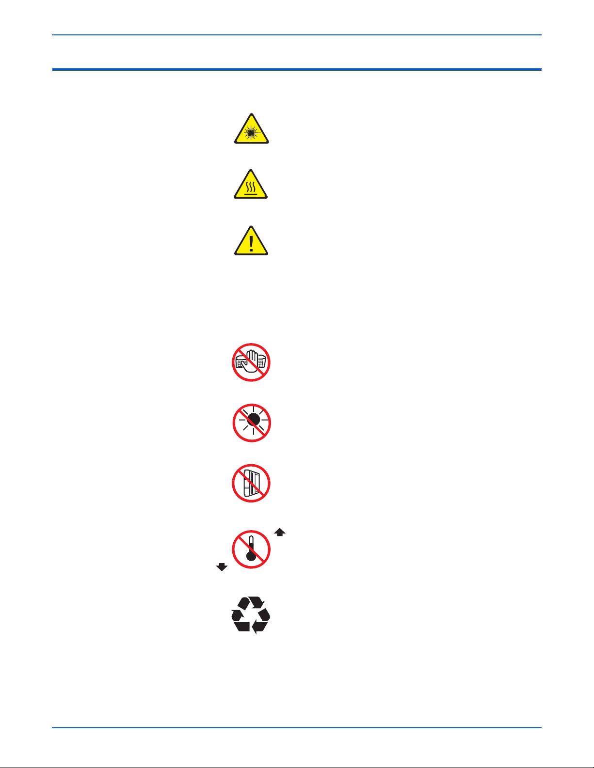
Symbols Marked on the Product
Warning. Danger invisible laser radiation when open. Avoid
direct exposure to beam.
Hot surface on or in the printer. Use caution to avoid personal
injury.
Warning. Use caution to avoid personal injury.
Use caution (or draws attention to a particular component).
Refer to the manual(s) for information.
0°C
32°F
Do not touch the OPC Drum.
Do not expose the item to sunlight.
Do not tilt the Print Cartridge.
35°C
Do not expose item to extreme temperature.
95°F
Recycle the item.
iv Phaser 3600 Printer Service Manual
Page 6

Power Safety Precautions
Power Source
Disconnecting Power
For 115 VAC printers, do not apply more than 127 volts RMS between the
supply conductors or between either supply conductor and ground. For 230
VAC printers, do not apply more than 254 volts RMS between the supply
conductors or between either supply conductor and ground. Use only the
specified power cord and connector. This manual assumes that the reader is
a qualified service technician.
Plug the three-wire power cord (with grounding prong) into a grounded AC
outlet only. If necessary, contact a licensed electrician to install a properly
grounded outlet. If the product loses its ground connection, contact with
conductive parts may cause an electrical shock. A protective ground
connection by way of the grounding conductor in the power cord is essential
for safe operation.
Warning
Turning the power Off using the power switch does not completely deenergize the printer. You must also disconnect the power cord from the
printer’s Alternating Current (AC) inlet. Disconnect the power cord by pulling
the plug, not the cord.
Disconnect the power cord in the following cases:
■ if the power cord or plug is frayed or otherwise damaged,
■ if any liquid or foreign material is spilled into the product,
■ if the printer is exposed to any excess moisture,
■ if the printer is dropped or damaged,
■ if you suspect that the product needs ser vi cing or repa ir,
■ whenever you clean the product.
Phaser 3600 Printer Service Manual v
Page 7

Electrostatic Discharge Precautions
Some semiconductor components, and the respective sub-assemblies that
contain them, are vulnerable to damage by Electrostatic Discharge (ESD).
These components include Integrated Circuits (ICs), Large-Scale Integrated
circuits (LSIs), field-effect transistors, and other semiconductor chip
components. The following techniques will reduce the occurrence of
component damage caused by static electricity.
Be sure the power is Off to the chassis or circuit board, and observe all other
safety precautions.
■ Immediately before handling any semiconductor components assemblies,
drain the electrostatic charge from your body. This can be accomplished
by touching an earth ground source or by wearing a wrist strap device
connected to an earth ground source. Wearing a wrist strap will also
prevent accumulation of additional bodily static charges. Be sure to
remove the wrist strap before applying power to the unit under test to
avoid potential shock.
■ After removing a static sensitive assembly from its anti-static bag, place it
on a grounded conductive surface. If the anti-static bag is conductive, you
may ground the bag and use it as a conductive surface.
■ Do not use freon-propelled chemicals. These can generate electrical
charges sufficient to damage some devices.
■ Do not remove a replacement component or electrical sub-assembly from
its protective package until you are ready to install it.
■ Immediately before removing the protective material from the leads of a
replacement device, touch the protective material to the chassis or circuit
assembly into which the device will be installed.
■ Minimize body motions when handling unpacked replacement devices.
Motion such as your clothes brushing together, or lifting a foot from a
carpeted floor can generate enough static electricity to damage an
electro-statically sensitive device.
■ Handle IC’s and Erasable Programmable Read-Only Memories
(EPROM’s) carefully to avoid bending pins.
■ Pay attention to the direction of parts when mounting or inserting them on
Printed Circuit Boards (PCB’s).
vi Phaser 3600 Printer Service Manual
Page 8

Service Safety Summary
General Guidelines and Safety precautions:
Warning Labels
For qualified service personnel only: Refer also to the preceding “Power Safety
Precautions” on page v.
Avoid servicing alone: Do not perform internal service or adjustment of this
product unless another person capable of rendering first aid or resuscitation is
present.
Use care when servicing with power: Dangerous voltages may exist at several
points in this product. To avoid personal injury, do not touch exposed
connections and components while power is On. Disconnect power before
removing the power supply shield or replacing components.
Do not wear jewelry: Remove jewelry prior to servicing. Rings, necklaces, and
other metallic objects could come into contact with dangerous voltages and
currents.
Read and obey all posted warning labels. Throughout the printer, warning
labels are displayed on potentially dangerous components. As you service the
printer, check to make certain that all warning labels remain in place.
Safety Interlocks
Make sure all covers are in place and all Interlock Switches are functioning
correctly after you have completed a printer service call. If you bypass an
Interlock Switch during a service call, use extreme caution when working on
or around the printer.
Class 1 Laser Product
The Phaser 3600 is certified to comply with Laser Product Performance
Standards set by the U.S. Department of Health and Human Services as a
Class 1 Laser Product. This means that this product does not emit hazardous
laser radiation; which is possible only because the laser beam is totally
enclosed during all modes of customer operation. When servicing the printer
or laser unit, follow the procedures specified in this manual and there will be
no hazards from the laser.
Phaser 3600 Printer Service Manual vii
Page 9
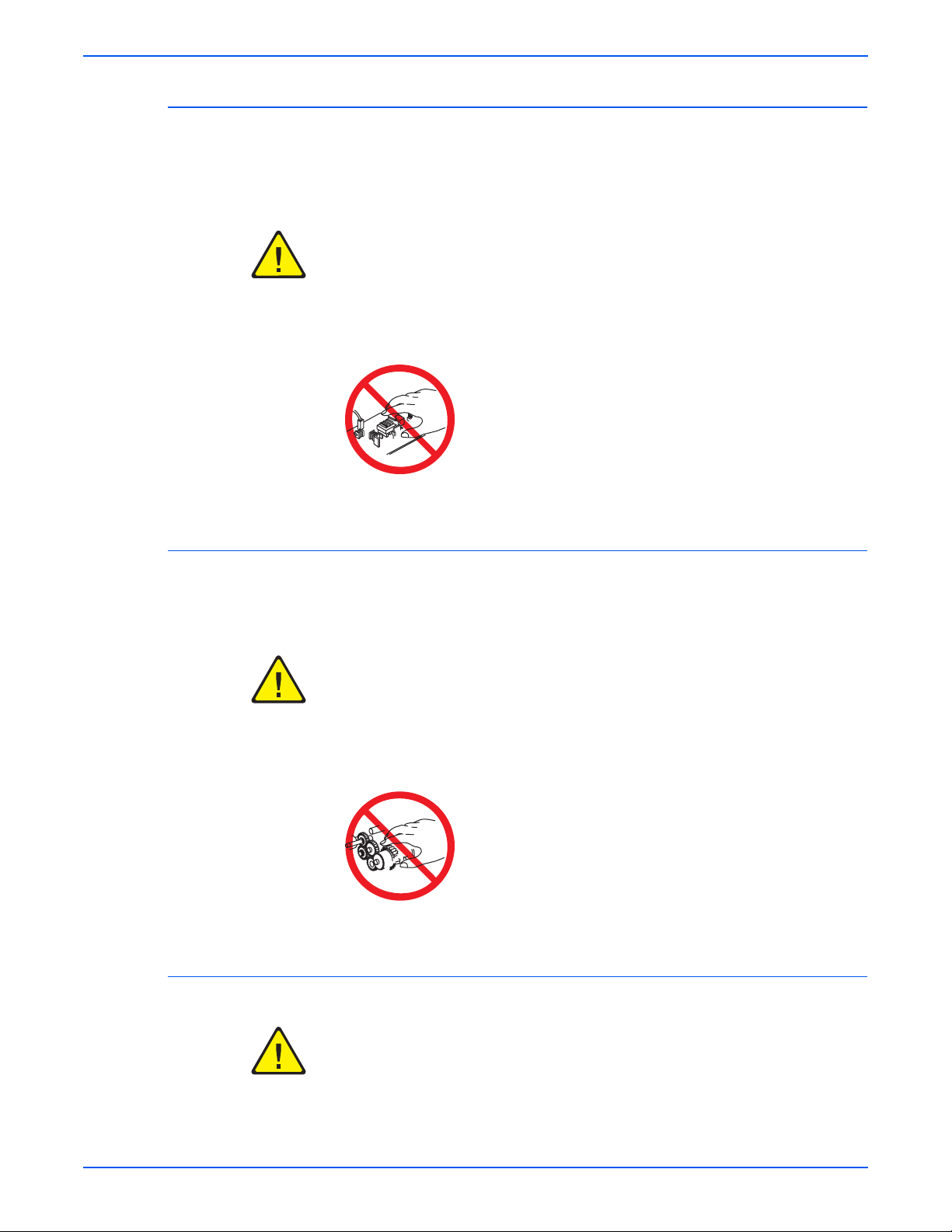
Servicing Electrical Components
Before starting any service procedure, switch the printer power Off and
unplug the power cord from the wall outlet. If you must service the printer with
power applied, be aware of the potential for electrical shock.
Warning
Do not touch any electrical component unless you are instructed to do so by a
service proc edure.
Servicing Mechanical Components
When servicing mechanical components within the printer, manually rotate
the Drive Assemblies, Rollers, and Gears.
Warning
Do not try to manually rotate or manually stop the drive assemblies while any
printer motor is running.
Servicing Fuser Components
Warning
This printer uses heat to fuse the toner image to paper. The Fuser is VERY
HOT. Turn the printer power Off and wait at least 5 minutes for the Fuser to
cool before attempting to service the Fuse r or adjacent compo nen ts.
viii Phaser 3600 Printer Service Manual
Page 10

Regulatory Information
United States (FCC Regulations)
Xerox has tested this product to electromagnetic emission and immunity
standards. These standards are designed to mitigate interference caused or
received by this product in a typical office environment.
This equipment has been tested and found to comply with the limits for a
Class B digital device, pursuant to Part 15 of the Federal Communications
Commission (FCC) Rules. These limits are designed to provide reasonable
protection against harmful interference in a residential installation. This
equipment generates, uses, and can radiate radio frequency energy. If it is not
installed and used in accordance with these instructions, it may cause harmful
interference to radio communications. However, there is no guarantee that
interference will not occur in a particular installation. If this equipment does
cause harmful interference to radio or television reception, which can be
determined by turning the equipment Off and On, the user is encouraged to
try to correct the interference by one or more of the following measures:
■ Reorient or relocate the receiver (device being interfered with).
■ Increase the separation between the printer and the receiver.
■ Connect the equipment into an outlet on a circuit different from that which
■ Consult the dealer or an experienced radio/television technician for help.
Any changes or modifications not expressly approved by Xerox could void the
user's authority to operate the equipment. To ensure compliance with Part 15
of the FCC rules, use shielded interface cables.
Canada (Regulations)
This Class B digital apparatus complies with Canadian ICES-003.
Cet appareil numérique de la classe B est conforme à la norme NMB-003 du
Canada
the receiver is connected.
.
Phaser 3600 Printer Service Manual ix
Page 11

European Union
The CE mark applied to this product symbolizes Xerox’s
declaration of conformit y with the following applicable
Directives of the European Union as of the dates indicated:
December 12, 2006: Council Directive 2006/95/EC as amended. Approximation of
the laws of the member states related to low voltage equipment.
December 15, 2004: Council Directive 2004/108/EC as amended. Approximation of
the laws of the member states related to electromagnetic compability.
This product, if used properly in accordance with the user's instructions, is
neither dangerous for the consumer nor for the environment.
To ensure compliance with European Union regulations, use shielded
interface cables.
A full declaration of conformity , defining the relevant directives and referenced
standards, can be obtained from your Xerox Limited representative.
x Phaser 3600 Printer Service Manual
Page 12

Manual Organization
The Phaser 3600 Printer Service Manual is the primary document used for
repairing, maintaining, and troubleshooting the printer. Use this manual as
your primary resource for understanding the operational characteristics of the
printer and all available options. This manual describes specifications, theory,
and the diagnosis and repair of problems occurring in the print engine and
attached options. Also included are detailed replacement procedures, parts
lists, and wiring diagrams.
The Phaser 3600 Printer Service Manual contains these chapters:
Introductory, Safety, and Regulatory Information: This section contains important
safety information and regulatory requirements.
Chapter 1 - General Information: This chapter contains an overview of the
printer’s operation, configuration, specifications, and consumables.
Chapter 2 - Theory of Operation: This chapter contains detailed functional
information on the printer components.
Chapter 3 - Error Messages: This chapter provides detailed troubleshooting
procedures for error messages generated by resident diagnostics.
Chapter 4 - General Troubleshooting: This chapter contains general information
on troubleshooting the printer. In addition, this chapter includes
troubleshooting methods for situations where error indicators are not
available.
Chapter 5 - Print-Quality Troubleshooting: Th is chapter f ocuses on t echniques to
correct image quality problems associated with the printer output.
Chapter 6- Cleaning and Maintenance: This chapter provides periodic cleaning
procedures for the printer.
Chapter 7- Service Parts Disassembly:
procedures for spare parts listed in the Parts List. A replacement procedure is
included when necessary.
Chapter 8- Parts List: Th
and optional Field Replaceable Units (FRUs), as well as part numbers for
orderable parts.
Chapter 9- Plug/Jack and Wiring Diagrams: This chapter contains the plug/jack
locations and the wiri ng dia grams for the printer.
Reference: This section provides a list of acronyms and abbreviations
is chapter contains exploded views of the print engine
This chapter contains removal
Phaser 3600 Printer Service Manual xi
Page 13

Service Terms . . . . . . . . . . . . . . . . . . . . . . . . . . . . . . . . . . . . . . . . . . . . . . . . . . . . . . . . . . . . . . . . . . . . . . . . . . . . . . . . iii
Symbols Marked on the Product . . . . . . . . . . . . . . . . . . . . . . . . . . . . . . . . . . . . . . . . . . . . . . . . . . . . . . . . . . . . . . . . . . iv
Power Safety Precautions . . . . . . . . . . . . . . . . . . . . . . . . . . . . . . . . . . . . . . . . . . . . . . . . . . . . . . . . . . . . . . . . . . . . . . . . v
Electrostatic Discharge Precautions. . . . . . . . . . . . . . . . . . . . . . . . . . . . . . . . . . . . . . . . . . . . . . . . . . . . . . . . . . . . . . . . vi
Service Safety Summary . . . . . . . . . . . . . . . . . . . . . . . . . . . . . . . . . . . . . . . . . . . . . . . . . . . . . . . . . . . . . . . . . . . . . . . . vii
Regulatory Information . . . . . . . . . . . . . . . . . . . . . . . . . . . . . . . . . . . . . . . . . . . . . . . . . . . . . . . . . . . . . . . . . . . . . . . . . ix
Manual Organization . . . . . . . . . . . . . . . . . . . . . . . . . . . . . . . . . . . . . . . . . . . . . . . . . . . . . . . . . . . . . . . . . . . . . . . . . . . xi
1 General Information
Printer Configurations . . . . . . . . . . . . . . . . . . . . . . . . . . . . . . . . . . . . . . . . . . . . . . . . . . . . . . . . . . . . . . . . . . . . . . . . . 1-2
Printer Options and Supplies. . . . . . . . . . . . . . . . . . . . . . . . . . . . . . . . . . . . . . . . . . . . . . . . . . . . . . . . . . . . . 1-2
Consumable and Service Part Life Expectancy. . . . . . . . . . . . . . . . . . . . . . . . . . . . . . . . . . . . . . . . . . . . . . . . . . . . . . . 1-3
Parts of the Printer. . . . . . . . . . . . . . . . . . . . . . . . . . . . . . . . . . . . . . . . . . . . . . . . . . . . . . . . . . . . . . . . . . . . . . . . . . . . 1-4
Front View . . . . . . . . . . . . . . . . . . . . . . . . . . . . . . . . . . . . . . . . . . . . . . . . . . . . . . . . . . . . . . . . . . . . . . . . . . . 1-4
Rear View . . . . . . . . . . . . . . . . . . . . . . . . . . . . . . . . . . . . . . . . . . . . . . . . . . . . . . . . . . . . . . . . . . . . . . . . . . . 1-4
Control Panel . . . . . . . . . . . . . . . . . . . . . . . . . . . . . . . . . . . . . . . . . . . . . . . . . . . . . . . . . . . . . . . . . . . . . . . . . . . . . . . . 1-5
Menu Map . . . . . . . . . . . . . . . . . . . . . . . . . . . . . . . . . . . . . . . . . . . . . . . . . . . . . . . . . . . . . . . . . . . . . . . . . . . 1-5
Error and Warning Messages . . . . . . . . . . . . . . . . . . . . . . . . . . . . . . . . . . . . . . . . . . . . . . . . . . . . . . . . . . . . 1-5
Printer Specifications. . . . . . . . . . . . . . . . . . . . . . . . . . . . . . . . . . . . . . . . . . . . . . . . . . . . . . . . . . . . . . . . . . . . . . . . . . 1-6
Printer Location and Clearance . . . . . . . . . . . . . . . . . . . . . . . . . . . . . . . . . . . . . . . . . . . . . . . . . . . . . . . . . . . 1-6
Printer Physical Specifications . . . . . . . . . . . . . . . . . . . . . . . . . . . . . . . . . . . . . . . . . . . . . . . . . . . . . . . . . . . 1-7
Functional Specifications. . . . . . . . . . . . . . . . . . . . . . . . . . . . . . . . . . . . . . . . . . . . . . . . . . . . . . . . . . . . . . . . 1-7
Electrical Specifications. . . . . . . . . . . . . . . . . . . . . . . . . . . . . . . . . . . . . . . . . . . . . . . . . . . . . . . . . . . . . . . . . 1-9
Environmental Specification . . . . . . . . . . . . . . . . . . . . . . . . . . . . . . . . . . . . . . . . . . . . . . . . . . . . . . . . . . . . . 1-9
Media and Tray Specifications . . . . . . . . . . . . . . . . . . . . . . . . . . . . . . . . . . . . . . . . . . . . . . . . . . . . . . . . . . . . . . . . . . 1-10
Table Of Contents
Table Of Contents
2 Theory of Operation
Phaser 3600 Operational Overview . . . . . . . . . . . . . . . . . . . . . . . . . . . . . . . . . . . . . . . . . . . . . . . . . . . . . . . . . . . . . . . 2-2
Summary of the Printing Process . . . . . . . . . . . . . . . . . . . . . . . . . . . . . . . . . . . . . . . . . . . . . . . . . . . . . . . . . 2-2
Print Cartridge and Print Modes . . . . . . . . . . . . . . . . . . . . . . . . . . . . . . . . . . . . . . . . . . . . . . . . . . . . . . . . . . 2-3
Printer Paper Path . . . . . . . . . . . . . . . . . . . . . . . . . . . . . . . . . . . . . . . . . . . . . . . . . . . . . . . . . . . . . . . . . . . . . . . . . . . . 2-4
Paper Path Components . . . . . . . . . . . . . . . . . . . . . . . . . . . . . . . . . . . . . . . . . . . . . . . . . . . . . . . . . . . . . . . . 2-4
Duplex Paper Path. . . . . . . . . . . . . . . . . . . . . . . . . . . . . . . . . . . . . . . . . . . . . . . . . . . . . . . . . . . . . . . . . . . . . 2-5
Print Engine Assemblies . . . . . . . . . . . . . . . . . . . . . . . . . . . . . . . . . . . . . . . . . . . . . . . . . . . . . . . . . . . . . . . . . . . . . . . 2-6
Image Processing Assembly and Main Board . . . . . . . . . . . . . . . . . . . . . . . . . . . . . . . . . . . . . . . . . . . . . . . . 2-6
Laser Scan Unit (LSU). . . . . . . . . . . . . . . . . . . . . . . . . . . . . . . . . . . . . . . . . . . . . . . . . . . . . . . . . . . . . . . . . . 2-7
Motor Drive Assemblies . . . . . . . . . . . . . . . . . . . . . . . . . . . . . . . . . . . . . . . . . . . . . . . . . . . . . . . . . . . . . . . . 2-7
Feed Assembly Process and Components. . . . . . . . . . . . . . . . . . . . . . . . . . . . . . . . . . . . . . . . . . . . . . . . . . . 2-7
Transfer Roller Assembly . . . . . . . . . . . . . . . . . . . . . . . . . . . . . . . . . . . . . . . . . . . . . . . . . . . . . . . . . . . . . . . 2-8
Fuser Assembly . . . . . . . . . . . . . . . . . . . . . . . . . . . . . . . . . . . . . . . . . . . . . . . . . . . . . . . . . . . . . . . . . . . . . . . 2-8
Duplex and Tray Assemblies . . . . . . . . . . . . . . . . . . . . . . . . . . . . . . . . . . . . . . . . . . . . . . . . . . . . . . . . . . . . . . . . . . . . 2-9
Duplex Assembly. . . . . . . . . . . . . . . . . . . . . . . . . . . . . . . . . . . . . . . . . . . . . . . . . . . . . . . . . . . . . . . . . . . . . . 2-9
Tray 2 and Optional Tray 3 Assemblies . . . . . . . . . . . . . . . . . . . . . . . . . . . . . . . . . . . . . . . . . . . . . . . . . . . . . 2-9
Printer Controls . . . . . . . . . . . . . . . . . . . . . . . . . . . . . . . . . . . . . . . . . . . . . . . . . . . . . . . . . . . . . . . . . . . . . . . . . . . . . 2-10
Paper Size Control. . . . . . . . . . . . . . . . . . . . . . . . . . . . . . . . . . . . . . . . . . . . . . . . . . . . . . . . . . . . . . . . . . . . 2-10
Automatic Paper Pick Control . . . . . . . . . . . . . . . . . . . . . . . . . . . . . . . . . . . . . . . . . . . . . . . . . . . . . . . . . . . 2-10
Laser Scan Unit (LSU) Control . . . . . . . . . . . . . . . . . . . . . . . . . . . . . . . . . . . . . . . . . . . . . . . . . . . . . . . . . . 2-11
Laser Light Intensity Control . . . . . . . . . . . . . . . . . . . . . . . . . . . . . . . . . . . . . . . . . . . . . . . . . . . . . . . . . . . . 2-11
Toner Control . . . . . . . . . . . . . . . . . . . . . . . . . . . . . . . . . . . . . . . . . . . . . . . . . . . . . . . . . . . . . . . . . . . . . . . 2-11
Fuser Temperature Control . . . . . . . . . . . . . . . . . . . . . . . . . . . . . . . . . . . . . . . . . . . . . . . . . . . . . . . . . . . . . 2-12
Phaser 3600 Color Laser Printer Service Manual 1
Page 14

Sensor Functions. . . . . . . . . . . . . . . . . . . . . . . . . . . . . . . . . . . . . . . . . . . . . . . . . . . . . . . . . . . . . . . . . . . . . . . . . . . . 2-13
Sensor Types. . . . . . . . . . . . . . . . . . . . . . . . . . . . . . . . . . . . . . . . . . . . . . . . . . . . . . . . . . . . . . . . . . . . . . . . 2-13
Sensors in the Paper Path . . . . . . . . . . . . . . . . . . . . . . . . . . . . . . . . . . . . . . . . . . . . . . . . . . . . . . . . . . . . . . 2-15
Power Supplies . . . . . . . . . . . . . . . . . . . . . . . . . . . . . . . . . . . . . . . . . . . . . . . . . . . . . . . . . . . . . . . . . . . . . . . . . . . . . 2-17
High Voltage Power Supply (HVPS) . . . . . . . . . . . . . . . . . . . . . . . . . . . . . . . . . . . . . . . . . . . . . . . . . . . . . . 2-17
Switching Mode Power Supply (SMPS) . . . . . . . . . . . . . . . . . . . . . . . . . . . . . . . . . . . . . . . . . . . . . . . . . . . 2-18
3 Error Messages
Troubleshooting Overview . . . . . . . . . . . . . . . . . . . . . . . . . . . . . . . . . . . . . . . . . . . . . . . . . . . . . . . . . . . . . . . . . . . . . . 3-2
Using the Troubleshooting Procedures . . . . . . . . . . . . . . . . . . . . . . . . . . . . . . . . . . . . . . . . . . . . . . . . . . . . . 3-2
Service Diagnostics . . . . . . . . . . . . . . . . . . . . . . . . . . . . . . . . . . . . . . . . . . . . . . . . . . . . . . . . . . . . . . . . . . . . . . . . . . . 3-3
Service Diagnostics Menu Map . . . . . . . . . . . . . . . . . . . . . . . . . . . . . . . . . . . . . . . . . . . . . . . . . . . . . . . . . . . . . . . . . . 3-3
Entering Service Diagnostics. . . . . . . . . . . . . . . . . . . . . . . . . . . . . . . . . . . . . . . . . . . . . . . . . . . . . . . . . . . . . 3-3
Service Diagnostic Control Panel Button Descriptions . . . . . . . . . . . . . . . . . . . . . . . . . . . . . . . . . . . . . . . . . 3-4
Diagnostic Test Menu Map . . . . . . . . . . . . . . . . . . . . . . . . . . . . . . . . . . . . . . . . . . . . . . . . . . . . . . . . . . . . . . 3-5
Troubleshooting Error Messages. . . . . . . . . . . . . . . . . . . . . . . . . . . . . . . . . . . . . . . . . . . . . . . . . . . . . . . . . . . . . . . . 3-11
Jam At Tray [1] [2] [3] (Jam 0). . . . . . . . . . . . . . . . . . . . . . . . . . . . . . . . . . . . . . . . . . . . . . . . . . . . . . . . . . 3-13
Jam At Top (Jam 1). . . . . . . . . . . . . . . . . . . . . . . . . . . . . . . . . . . . . . . . . . . . . . . . . . . . . . . . . . . . . . . . . . . 3-14
Jam At Exit (Jam 2). . . . . . . . . . . . . . . . . . . . . . . . . . . . . . . . . . . . . . . . . . . . . . . . . . . . . . . . . . . . . . . . . . . 3-15
Jam At Rear (Duplex Jam 1) . . . . . . . . . . . . . . . . . . . . . . . . . . . . . . . . . . . . . . . . . . . . . . . . . . . . . . . . . . . . 3-16
Jam At Duplex (Duplex Jam 2) . . . . . . . . . . . . . . . . . . . . . . . . . . . . . . . . . . . . . . . . . . . . . . . . . . . . . . . . . . 3-17
Check Cartridge, Invalid Print Cartridge, Non-Xerox Cartridge, Replace Print Cartridge . . . . . . . . . . . . . . . 3-18
Close Fuser Door. . . . . . . . . . . . . . . . . . . . . . . . . . . . . . . . . . . . . . . . . . . . . . . . . . . . . . . . . . . . . . . . . . . . . 3-19
Close Top Cover . . . . . . . . . . . . . . . . . . . . . . . . . . . . . . . . . . . . . . . . . . . . . . . . . . . . . . . . . . . . . . . . . . . . . 3-19
Fuser Failure, Engine Fuser Low Heat Error, or Engine Fuser Over Heat Error. . . . . . . . . . . . . . . . . . . . . . . 3-20
Laser Failure . . . . . . . . . . . . . . . . . . . . . . . . . . . . . . . . . . . . . . . . . . . . . . . . . . . . . . . . . . . . . . . . . . . . . . . . 3-21
Output Tray is Full . . . . . . . . . . . . . . . . . . . . . . . . . . . . . . . . . . . . . . . . . . . . . . . . . . . . . . . . . . . . . . . . . . . . 3-22
4 General Troubleshooting
Servicing Instructions . . . . . . . . . . . . . . . . . . . . . . . . . . . . . . . . . . . . . . . . . . . . . . . . . . . . . . . . . . . . . . . . . . . . . . . . . 4-2
Preventive Maintenance Procedure . . . . . . . . . . . . . . . . . . . . . . . . . . . . . . . . . . . . . . . . . . . . . . . . . . . . . . . . . . . . . . . 4-3
Recommended Tools. . . . . . . . . . . . . . . . . . . . . . . . . . . . . . . . . . . . . . . . . . . . . . . . . . . . . . . . . . . . . . . . . . . 4-3
Control Panel Troubleshooting . . . . . . . . . . . . . . . . . . . . . . . . . . . . . . . . . . . . . . . . . . . . . . . . . . . . . . . . . . . . . . . . . . 4-4
No Control Panel Display after Power Is Turned ON . . . . . . . . . . . . . . . . . . . . . . . . . . . . . . . . . . . . . . . . . . . 4-4
Control Panel LED is On, Control Panel Display Is Blank. . . . . . . . . . . . . . . . . . . . . . . . . . . . . . . . . . . . . . . . 4-4
Power Supply Troubleshooting . . . . . . . . . . . . . . . . . . . . . . . . . . . . . . . . . . . . . . . . . . . . . . . . . . . . . . . . . . . . . . . . . . 4-5
Taking Voltage Measurements. . . . . . . . . . . . . . . . . . . . . . . . . . . . . . . . . . . . . . . . . . . . . . . . . . . . . . . . . . . . 4-5
5 Print-Quality Troubleshooting
Print-Quality Problems Overview. . . . . . . . . . . . . . . . . . . . . . . . . . . . . . . . . . . . . . . . . . . . . . . . . . . . . . . . . . . . . . . . . 5-2
Repeating Defects . . . . . . . . . . . . . . . . . . . . . . . . . . . . . . . . . . . . . . . . . . . . . . . . . . . . . . . . . . . . . . . . . . . . . . . . . . . . 5-3
Repeating Defects Measurement Table . . . . . . . . . . . . . . . . . . . . . . . . . . . . . . . . . . . . . . . . . . . . . . . . . . . . . 5-4
Control Panel (Internal) Test Print . . . . . . . . . . . . . . . . . . . . . . . . . . . . . . . . . . . . . . . . . . . . . . . . . . . . . . . . . . . . . . . . 5-4
2 Phaser 3600 Printer Service Manual
Page 15

Image-Quality Troubleshooting . . . . . . . . . . . . . . . . . . . . . . . . . . . . . . . . . . . . . . . . . . . . . . . . . . . . . . . . . . . . . . . . . . 5-9
Blank Print (No Print) . . . . . . . . . . . . . . . . . . . . . . . . . . . . . . . . . . . . . . . . . . . . . . . . . . . . . . . . . . . . . . . . . . 5-9
Light or Undertone Print . . . . . . . . . . . . . . . . . . . . . . . . . . . . . . . . . . . . . . . . . . . . . . . . . . . . . . . . . . . . . . . 5-11
Black Print . . . . . . . . . . . . . . . . . . . . . . . . . . . . . . . . . . . . . . . . . . . . . . . . . . . . . . . . . . . . . . . . . . . . . . . . . . 5-13
Background Contamination . . . . . . . . . . . . . . . . . . . . . . . . . . . . . . . . . . . . . . . . . . . . . . . . . . . . . . . . . . . . . 5-15
Residual Image or Ghosting . . . . . . . . . . . . . . . . . . . . . . . . . . . . . . . . . . . . . . . . . . . . . . . . . . . . . . . . . . . . 5-16
Faded or Missing Image . . . . . . . . . . . . . . . . . . . . . . . . . . . . . . . . . . . . . . . . . . . . . . . . . . . . . . . . . . . . . . . 5-18
Random Spots. . . . . . . . . . . . . . . . . . . . . . . . . . . . . . . . . . . . . . . . . . . . . . . . . . . . . . . . . . . . . . . . . . . . . . . 5-20
Repeating Bands, Lines, Marks, or Spots . . . . . . . . . . . . . . . . . . . . . . . . . . . . . . . . . . . . . . . . . . . . . . . . . . 5-22
Unfused Image . . . . . . . . . . . . . . . . . . . . . . . . . . . . . . . . . . . . . . . . . . . . . . . . . . . . . . . . . . . . . . . . . . . . . . 5-24
Skew . . . . . . . . . . . . . . . . . . . . . . . . . . . . . . . . . . . . . . . . . . . . . . . . . . . . . . . . . . . . . . . . . . . . . . . . . . . . . . 5-25
Horizontal Band, Voids, or Streaks . . . . . . . . . . . . . . . . . . . . . . . . . . . . . . . . . . . . . . . . . . . . . . . . . . . . . . . 5-27
6 Cleaning and Maintenance
Service Maintenance Procedure. . . . . . . . . . . . . . . . . . . . . . . . . . . . . . . . . . . . . . . . . . . . . . . . . . . . . . . . . . . . . . . . . . 6-2
Recommended Tools. . . . . . . . . . . . . . . . . . . . . . . . . . . . . . . . . . . . . . . . . . . . . . . . . . . . . . . . . . . . . . . . . . . 6-2
General Cleaning . . . . . . . . . . . . . . . . . . . . . . . . . . . . . . . . . . . . . . . . . . . . . . . . . . . . . . . . . . . . . . . . . . . . . . . . . . . . . 6-2
Cleaning the Laser Scan Unit. . . . . . . . . . . . . . . . . . . . . . . . . . . . . . . . . . . . . . . . . . . . . . . . . . . . . . . . . . . . . 6-3
Cleaning the Print Cartridge. . . . . . . . . . . . . . . . . . . . . . . . . . . . . . . . . . . . . . . . . . . . . . . . . . . . . . . . . . . . . . 6-3
Control Panel Maintenance . . . . . . . . . . . . . . . . . . . . . . . . . . . . . . . . . . . . . . . . . . . . . . . . . . . . . . . . . . . . . . . . . . . . . 6-4
Cleaning the Drum. . . . . . . . . . . . . . . . . . . . . . . . . . . . . . . . . . . . . . . . . . . . . . . . . . . . . . . . . . . . . . . . . . . . . 6-4
Cleaning the Fuser. . . . . . . . . . . . . . . . . . . . . . . . . . . . . . . . . . . . . . . . . . . . . . . . . . . . . . . . . . . . . . . . . . . . . 6-4
Table Of Contents
7 Service Parts Disassembly
Service Overview . . . . . . . . . . . . . . . . . . . . . . . . . . . . . . . . . . . . . . . . . . . . . . . . . . . . . . . . . . . . . . . . . . . . . . . . . . . . . 7-2
General Notes on Disassembly . . . . . . . . . . . . . . . . . . . . . . . . . . . . . . . . . . . . . . . . . . . . . . . . . . . . . . . . . . . . . . . . . . 7-2
Preparation . . . . . . . . . . . . . . . . . . . . . . . . . . . . . . . . . . . . . . . . . . . . . . . . . . . . . . . . . . . . . . . . . . . . . . . . . . 7-2
Fastener Types . . . . . . . . . . . . . . . . . . . . . . . . . . . . . . . . . . . . . . . . . . . . . . . . . . . . . . . . . . . . . . . . . . . . . . . 7-4
Notations in the Disassembly Text. . . . . . . . . . . . . . . . . . . . . . . . . . . . . . . . . . . . . . . . . . . . . . . . . . . . . . . . . 7-5
Standard Orientation of the Printer . . . . . . . . . . . . . . . . . . . . . . . . . . . . . . . . . . . . . . . . . . . . . . . . . . . . . . . . 7-5
Covers and Control Panel. . . . . . . . . . . . . . . . . . . . . . . . . . . . . . . . . . . . . . . . . . . . . . . . . . . . . . . . . . . . . . . . . . . . . . . 7-6
Right Cover (PL 1.2.3). . . . . . . . . . . . . . . . . . . . . . . . . . . . . . . . . . . . . . . . . . . . . . . . . . . . . . . . . . . . . . . . . . 7-6
Left Cover (PL 1.2.2). . . . . . . . . . . . . . . . . . . . . . . . . . . . . . . . . . . . . . . . . . . . . . . . . . . . . . . . . . . . . . . . . . . 7-7
Rear Cover (PL 1.2.6) . . . . . . . . . . . . . . . . . . . . . . . . . . . . . . . . . . . . . . . . . . . . . . . . . . . . . . . . . . . . . . . . . . 7-8
Rear Cover Fan (PL1.2.6.10) . . . . . . . . . . . . . . . . . . . . . . . . . . . . . . . . . . . . . . . . . . . . . . . . . . . . . . . . . . . . . 7-9
Top Cover (PL 1.2.1). . . . . . . . . . . . . . . . . . . . . . . . . . . . . . . . . . . . . . . . . . . . . . . . . . . . . . . . . . . . . . . . . . 7-10
Access Door (PL 1.2.1.1) . . . . . . . . . . . . . . . . . . . . . . . . . . . . . . . . . . . . . . . . . . . . . . . . . . . . . . . . . . . . . . 7-12
Control Panel (PL 1.2.9) . . . . . . . . . . . . . . . . . . . . . . . . . . . . . . . . . . . . . . . . . . . . . . . . . . . . . . . . . . . . . . . 7-13
Tray 1 (MPT) Assembly . . . . . . . . . . . . . . . . . . . . . . . . . . . . . . . . . . . . . . . . . . . . . . . . . . . . . . . . . . . . . . . . . . . . . . . 7-14
Inner Cover (PL 1.2.5). . . . . . . . . . . . . . . . . . . . . . . . . . . . . . . . . . . . . . . . . . . . . . . . . . . . . . . . . . . . . . . . . 7-16
Tray 1 (MPT) Knock-Up Plate Only (PL 1.1.3). . . . . . . . . . . . . . . . . . . . . . . . . . . . . . . . . . . . . . . . . . . . . . . 7-17
Tray 1 (MPT) Pick-Up Rack (PL 1.3.2) . . . . . . . . . . . . . . . . . . . . . . . . . . . . . . . . . . . . . . . . . . . . . . . . . . . . 7-18
Retard Assembly (PL 1.3.49) . . . . . . . . . . . . . . . . . . . . . . . . . . . . . . . . . . . . . . . . . . . . . . . . . . . . . . . . . . . 7-19
Tray 1 (MPT) Separator Pad Assembly (PL 1.3.4). . . . . . . . . . . . . . . . . . . . . . . . . . . . . . . . . . . . . . . . . . . . 7-20
Tray 1 (MPT) Feed Sensor (PL1.3.97). . . . . . . . . . . . . . . . . . . . . . . . . . . . . . . . . . . . . . . . . . . . . . . . . . . . . 7-21
Paper Tray Empty Sensor (PL1.3.95) . . . . . . . . . . . . . . . . . . . . . . . . . . . . . . . . . . . . . . . . . . . . . . . . . . . . . 7-22
Paper Tray Empty Actuator (PL1.3.58) . . . . . . . . . . . . . . . . . . . . . . . . . . . . . . . . . . . . . . . . . . . . . . . . . . . . 7-23
Sub Toner Low Sensor Board (PL1.3.47) . . . . . . . . . . . . . . . . . . . . . . . . . . . . . . . . . . . . . . . . . . . . . . . . . . 7-24
Pick Roller and Shaft (PL 1.3.2.5). . . . . . . . . . . . . . . . . . . . . . . . . . . . . . . . . . . . . . . . . . . . . . . . . . . . . . . . 7-25
Tray 1 (MPT) Pick Roller Only (PL 1.3.2.4) . . . . . . . . . . . . . . . . . . . . . . . . . . . . . . . . . . . . . . . . . . . . . . . . . 7-28
Tray 1 (MPT) Solenoid (PL 1.1.26) . . . . . . . . . . . . . . . . . . . . . . . . . . . . . . . . . . . . . . . . . . . . . . . . . . . . . . . 7-29
Phaser 3600 Color Laser Printer Service Manual 3
Page 16

Tray 2 Pick-Up Assembly and Rollers . . . . . . . . . . . . . . . . . . . . . . . . . . . . . . . . . . . . . . . . . . . . . . . . . . . . . . . . . . . . 7-30
Pick-Up Gear and Bearing (PL 1.1.21). . . . . . . . . . . . . . . . . . . . . . . . . . . . . . . . . . . . . . . . . . . . . . . . . . . . . 7-34
Tray 2 Feed Roller (PL1.3.59.5). . . . . . . . . . . . . . . . . . . . . . . . . . . . . . . . . . . . . . . . . . . . . . . . . . . . . . . . . . 7-35
Tray 2 Pick Roller (PL1.3.59.2) . . . . . . . . . . . . . . . . . . . . . . . . . . . . . . . . . . . . . . . . . . . . . . . . . . . . . . . . . . 7-35
Tray 2 (PL2.1.0) and Optional Tray 3 (PL2.2.0) Replacement . . . . . . . . . . . . . . . . . . . . . . . . . . . . . . . . . . . . . . . . . . 7-36
Duplex Unit (PL2.3.0) . . . . . . . . . . . . . . . . . . . . . . . . . . . . . . . . . . . . . . . . . . . . . . . . . . . . . . . . . . . . . . . . . . . . . . . . 7-37
Main Drive and Registration Assemblies . . . . . . . . . . . . . . . . . . . . . . . . . . . . . . . . . . . . . . . . . . . . . . . . . . . . . . . . . . 7-38
Main Drive Assembly (PL 1.1.18) . . . . . . . . . . . . . . . . . . . . . . . . . . . . . . . . . . . . . . . . . . . . . . . . . . . . . . . . 7-38
Main Board (PL 1.1.19). . . . . . . . . . . . . . . . . . . . . . . . . . . . . . . . . . . . . . . . . . . . . . . . . . . . . . . . . . . . . . . . 7-39
Main Solenoid (PL 1.1.25). . . . . . . . . . . . . . . . . . . . . . . . . . . . . . . . . . . . . . . . . . . . . . . . . . . . . . . . . . . . . . 7-40
Registration Assembly (PL 1.1.12) . . . . . . . . . . . . . . . . . . . . . . . . . . . . . . . . . . . . . . . . . . . . . . . . . . . . . . . 7-41
Transfer Roller (PL 1.1.7) . . . . . . . . . . . . . . . . . . . . . . . . . . . . . . . . . . . . . . . . . . . . . . . . . . . . . . . . . . . . . . 7-43
Exit Roller (PL 1.3.6). . . . . . . . . . . . . . . . . . . . . . . . . . . . . . . . . . . . . . . . . . . . . . . . . . . . . . . . . . . . . . . . . . 7-44
Exit Gear (PL 1.3.9). . . . . . . . . . . . . . . . . . . . . . . . . . . . . . . . . . . . . . . . . . . . . . . . . . . . . . . . . . . . . . . . . . . 7-44
Outbin Full Actuator (PL 1.3.8) . . . . . . . . . . . . . . . . . . . . . . . . . . . . . . . . . . . . . . . . . . . . . . . . . . . . . . . . . . 7-45
Outbin Full Sensor (PL1.3.21). . . . . . . . . . . . . . . . . . . . . . . . . . . . . . . . . . . . . . . . . . . . . . . . . . . . . . . . . . . 7-46
Duplex Roller (PL 1.3.11) . . . . . . . . . . . . . . . . . . . . . . . . . . . . . . . . . . . . . . . . . . . . . . . . . . . . . . . . . . . . . . 7-47
Exit Solenoid (PL 1.1.16). . . . . . . . . . . . . . . . . . . . . . . . . . . . . . . . . . . . . . . . . . . . . . . . . . . . . . . . . . . . . . . 7-48
Frame Assembly . . . . . . . . . . . . . . . . . . . . . . . . . . . . . . . . . . . . . . . . . . . . . . . . . . . . . . . . . . . . . . . . . . . . . . . . . . . . 7-49
Feed Idle Unit (PL 1.3.50) . . . . . . . . . . . . . . . . . . . . . . . . . . . . . . . . . . . . . . . . . . . . . . . . . . . . . . . . . . . . . . 7-49
Pre-transfer Lamp (PTL) Board (PL 1.3.71) . . . . . . . . . . . . . . . . . . . . . . . . . . . . . . . . . . . . . . . . . . . . . . . . 7-50
Developer Drive Assembly (PL 1.1.17) . . . . . . . . . . . . . . . . . . . . . . . . . . . . . . . . . . . . . . . . . . . . . . . . . . . . 7-51
Joint Board (PL 1.3.61). . . . . . . . . . . . . . . . . . . . . . . . . . . . . . . . . . . . . . . . . . . . . . . . . . . . . . . . . . . . . . . . 7-52
Paper Size Sensor (PL 1.3.14). . . . . . . . . . . . . . . . . . . . . . . . . . . . . . . . . . . . . . . . . . . . . . . . . . . . . . . . . . . 7-53
Fuser Assembly (1.3.80) . . . . . . . . . . . . . . . . . . . . . . . . . . . . . . . . . . . . . . . . . . . . . . . . . . . . . . . . . . . . . . . . . . . . . . 7-54
Fuser Interlock Switch (PL 1.3.77) . . . . . . . . . . . . . . . . . . . . . . . . . . . . . . . . . . . . . . . . . . . . . . . . . . . . . . . 7-55
Fuser Exit Sensor (PL 1.3.76) . . . . . . . . . . . . . . . . . . . . . . . . . . . . . . . . . . . . . . . . . . . . . . . . . . . . . . . . . . . 7-56
Fuser Thermostat (PL 1.4.3) . . . . . . . . . . . . . . . . . . . . . . . . . . . . . . . . . . . . . . . . . . . . . . . . . . . . . . . . . . . . 7-57
Fuser Thermistor (PL 1.4.40) . . . . . . . . . . . . . . . . . . . . . . . . . . . . . . . . . . . . . . . . . . . . . . . . . . . . . . . . . . . 7-58
Heat Roller (PL 1.4.53) and Bushing (PL 1.4.44) . . . . . . . . . . . . . . . . . . . . . . . . . . . . . . . . . . . . . . . . . . . . 7-60
Dual-lamp (PL 1.4.56). . . . . . . . . . . . . . . . . . . . . . . . . . . . . . . . . . . . . . . . . . . . . . . . . . . . . . . . . . . . . . . . . 7-66
Pressure Roller (PL 1.4.66) and Bushing (PL 1.4.50) . . . . . . . . . . . . . . . . . . . . . . . . . . . . . . . . . . . . . . . . . 7-67
Laser Scan Unit (PL 1.1.15). . . . . . . . . . . . . . . . . . . . . . . . . . . . . . . . . . . . . . . . . . . . . . . . . . . . . . . . . . . . . . . . . . . . 7-70
LSU Lower Cover (PL 1.3.48) . . . . . . . . . . . . . . . . . . . . . . . . . . . . . . . . . . . . . . . . . . . . . . . . . . . . . . . . . . . 7-72
Left Side Cooling Supply Fan and Duct (PL 1.1.31). . . . . . . . . . . . . . . . . . . . . . . . . . . . . . . . . . . . . . . . . . . 7-73
Cover Open Board and Sensor (PL 1.3.47) . . . . . . . . . . . . . . . . . . . . . . . . . . . . . . . . . . . . . . . . . . . . . . . . . 7-74
Power Supplies . . . . . . . . . . . . . . . . . . . . . . . . . . . . . . . . . . . . . . . . . . . . . . . . . . . . . . . . . . . . . . . . . . . . . . . . . . . . . 7-75
High Voltage Power Supply (HVPS) (PL 1.1.29.1) . . . . . . . . . . . . . . . . . . . . . . . . . . . . . . . . . . . . . . . . . . . 7-75
Switched Mode Power Supply (PL 1.1.29.2). . . . . . . . . . . . . . . . . . . . . . . . . . . . . . . . . . . . . . . . . . . . . . . . 7-76
8 Parts List
Serial Number Format . . . . . . . . . . . . . . . . . . . . . . . . . . . . . . . . . . . . . . . . . . . . . . . . . . . . . . . . . . . . . . . . . . . . . . . . . 8-2
Serial Number Label Location . . . . . . . . . . . . . . . . . . . . . . . . . . . . . . . . . . . . . . . . . . . . . . . . . . . . . . . . . . . . . . . . . . . 8-3
Using the Parts List . . . . . . . . . . . . . . . . . . . . . . . . . . . . . . . . . . . . . . . . . . . . . . . . . . . . . . . . . . . . . . . . . . . . . . . . . . . 8-4
PL 1.1 Main Assembly . . . . . . . . . . . . . . . . . . . . . . . . . . . . . . . . . . . . . . . . . . . . . . . . . . . . . . . . . . . . . . . . . . . . . . . . . 8-6
PL 1.2 Cover Assembly . . . . . . . . . . . . . . . . . . . . . . . . . . . . . . . . . . . . . . . . . . . . . . . . . . . . . . . . . . . . . . . . . . . . . . . 8-10
PL 1.3 Frame Assembly (1 of 2) . . . . . . . . . . . . . . . . . . . . . . . . . . . . . . . . . . . . . . . . . . . . . . . . . . . . . . . . . . . . . . . . 8-12
PL 1.3 Frame Assembly (2 of 2) . . . . . . . . . . . . . . . . . . . . . . . . . . . . . . . . . . . . . . . . . . . . . . . . . . . . . . . . . . . . . . . . 8-13
PL 1.4 Fuser Assembly . . . . . . . . . . . . . . . . . . . . . . . . . . . . . . . . . . . . . . . . . . . . . . . . . . . . . . . . . . . . . . . . . . . . . . . 8-20
PL 2.1 Tray 2 Cassette. . . . . . . . . . . . . . . . . . . . . . . . . . . . . . . . . . . . . . . . . . . . . . . . . . . . . . . . . . . . . . . . . . . . . . . . 8-24
PL 2.2 Tray 3 Cassette. . . . . . . . . . . . . . . . . . . . . . . . . . . . . . . . . . . . . . . . . . . . . . . . . . . . . . . . . . . . . . . . . . . . . . . . 8-26
PL 2.3 Duplex Assembly . . . . . . . . . . . . . . . . . . . . . . . . . . . . . . . . . . . . . . . . . . . . . . . . . . . . . . . . . . . . . . . . . . . . . . 8-30
4 Phaser 3600 Printer Service Manual
Page 17

9 Plug/Jack and Wiring Diagrams
Plug/Jack Diagrams and Designators . . . . . . . . . . . . . . . . . . . . . . . . . . . . . . . . . . . . . . . . . . . . . . . . . . . . . . . . . . . . . 9-2
Plug/Jack and Connector Locators and Maps . . . . . . . . . . . . . . . . . . . . . . . . . . . . . . . . . . . . . . . . . . . . . . . . . . . . . . . 9-3
Printer Plug/Jack/Connector Designators . . . . . . . . . . . . . . . . . . . . . . . . . . . . . . . . . . . . . . . . . . . . . . . . . . . 9-3
Map 1- LSU and Fuser. . . . . . . . . . . . . . . . . . . . . . . . . . . . . . . . . . . . . . . . . . . . . . . . . . . . . . . . . . . . . . . . . . 9-4
Map 2- Main Board . . . . . . . . . . . . . . . . . . . . . . . . . . . . . . . . . . . . . . . . . . . . . . . . . . . . . . . . . . . . . . . . . . . . 9-5
Map 3- SMPS Board . . . . . . . . . . . . . . . . . . . . . . . . . . . . . . . . . . . . . . . . . . . . . . . . . . . . . . . . . . . . . . . . . . . 9-6
Map 4 - HVPS Board . . . . . . . . . . . . . . . . . . . . . . . . . . . . . . . . . . . . . . . . . . . . . . . . . . . . . . . . . . . . . . . . . . . 9-7
Wiring Diagrams . . . . . . . . . . . . . . . . . . . . . . . . . . . . . . . . . . . . . . . . . . . . . . . . . . . . . . . . . . . . . . . . . . . . . . . . . . . . . 9-8
Notations Used in the Wiring Diagrams. . . . . . . . . . . . . . . . . . . . . . . . . . . . . . . . . . . . . . . . . . . . . . . . . . . . . 9-8
General Wiring Diagram . . . . . . . . . . . . . . . . . . . . . . . . . . . . . . . . . . . . . . . . . . . . . . . . . . . . . . . . . . . . . . . 9-12
HVPS/SMPS to Main Board Wiring Diagram. . . . . . . . . . . . . . . . . . . . . . . . . . . . . . . . . . . . . . . . . . . . . . . . 9-13
Sensor to Main Board Wiring Diagram . . . . . . . . . . . . . . . . . . . . . . . . . . . . . . . . . . . . . . . . . . . . . . . . . . . . 9-14
Main Drive/Joint Board and Optional Tray Wiring Diagram . . . . . . . . . . . . . . . . . . . . . . . . . . . . . . . . . . . . .9-15
LSU and Main Motor to Main Board Wiring Diagram . . . . . . . . . . . . . . . . . . . . . . . . . . . . . . . . . . . . . . . . .9-16
Controller Unit and Duplex Board to Main Board Wiring Diagram . . . . . . . . . . . . . . . . . . . . . . . . . . . . . . . . 9-17
A Reference
Acronyms and Abbreviations . . . . . . . . . . . . . . . . . . . . . . . . . . . . . . . . . . . . . . . . . . . . . . . . . . . . . . . . . . . . . . . . . . . . A-2
Table Of Contents
Index
Phaser 3600 Color Laser Printer Service Manual 5
Page 18

General Information
In this chapter...
■ Printer Configuratio ns
■ Consumable and Service Part Life Expectancy
■ Parts of the Printer
■ Control Panel
■ Printer Specifications
■ Media and Tray Specifications
Chapter
1
Page 19

General Information
Printer Configurations
Print Features and Configurations
Printer Configurations
Features
Maximum Print Speed
tter
Le
Memory (Optional)
Up to 512 MB Optional if
e original DIMM is
th
replaced with 256MB RAM
DIMM and the second slot
has a 256MB RAM DIMM
PostScript and PCL Fonts Yes Yes Yes
Default Resolution
Maximum Resolution
500-Sheet Feeder (Tray 3) Optional Optional Optional Optional
Network Interface Not Optional Not Optional Standard Standard
Automatic 2-Sided Printing
(Separate Duplex
USB, Parallel Interface Yes Yes Yes Yes
Printer Options and Supplies
Unit)
3600_B 3600V_B 3600_N 3600V_N
40 ppm 40 ppm 40 ppm 40 ppm
64 MB 64 MB 128 MB 128 MB
600 x 600 dpi
1200 x 1200
dpi
Optional Optional Optional Standard
x 600 dpi
600
1200 x 1200
dpi
Options and Supplies
Printer Option Item Part Number
Memory 64 MB additional RAM memory
128 MB additional RAM memory
256 MB additional RAM memory
Optional Units Duplex Unit
500-Sheet Feeder
Cartridges Standard-Capacity Print Cartridge
00 pages)
(7,0
gh-Capacity Print Cartridge (14,000
Hi
pages)
Extra High-Capacity Print Cartridge
,
000 pages)
(20
Metered/Pagepack Print cartridge
000 pages)
(20,
Gear Lubricant Xerox lubricant Plastislip grease 043E00550
1-2 Phaser 3600 Printer Service Manual
097S03759
097S03760
097S03761
097S03387
097S03385
106R01370
106R01371
106R01372
106R01369
Page 20

Consumable and Service Part Life Expectancy
Not
Consumable (toner/print cartridge) usage is tracked by the CRUM and
monitored by the Main Board in order to display the near end-of-life and endof-life messages. Life ratings are based on 5% coverage and an average 4
page job length.
Consumables Print Life
Print Cartridge Standard Capacity 7,000 pages
Service Parts
Fuser Assembly 150,000 pages
Transfer Roller 150,000 pages
Feed Roller Kit 150,000 pages
General Information
High Capacity 14,000 pages
Extra High Capacity 20,000 pages
Metered/Pagepack 20,000 pages
Retard Roller 150,000 pages
Separator Pad 150,000 pages
e
The service parts are not tracked with an NVRAM counter and there is no
replace or low warnings associated with these service parts.
Phaser 3600 Printer Service Manual 1-3
Page 21
General Information
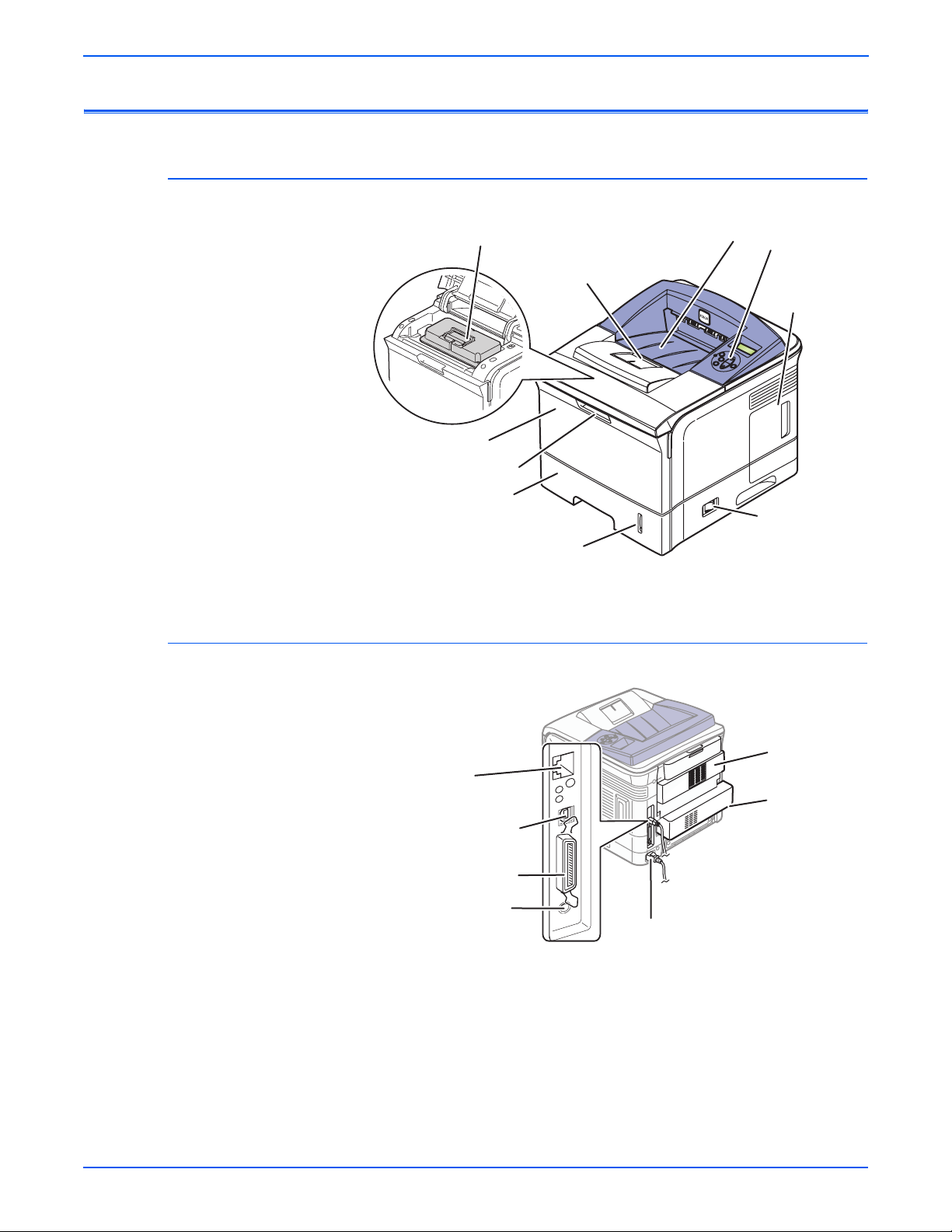
Parts of the Printer
Front View
Rear View
Print Cartridge
Paper Output Support
Tray 1 (MPT)
Tray 1 (MPT) Release
Tray 2
Paper Gauge
Output Tray
Control Panel
Control Board
Cover
On/Off Switch
s3600-001
Network Port
(optional for 3500B)
IEEE 1284 Parallel Port
Tray 3 Optional
Cable Connector
1-4 Phaser 3600 Printer Service Manual
USB Port
Power Cord Receptacle
Rear Door
Duplex Unit
(optional)
s3600-112
Page 22

Control Panel
The Control Panel has three components:
■ Multi-colored Light Emitting Diode (LED) light
■ Alphanumeric disp lay
■ Six-button cluster
Control Panel Buttons
Button Function
Return Returns to the prior higher level menu structure, if
able.
l
avai
CANCEL Terminates the current action.
MENU Cycles through all of the top level menu items.
UP Scrolls up one menu item within a menu list. If you
con
inually press this control, the menu items will ‘wrap’.
t
General Information
DOWN Scrolls up one menu item within a menu list. If you
OK Executes the highlighted menu item.
Menu Map
The Menu Map is a visual representation of the Control Panel settings and
information pages. All Menu Map settings are documented in the User Guide.
Error and Warning Messages
When there is a problem with the printer, the Control Panel LED (3) blinks red
for an error and a warning. An error or warning message is displayed in the
Alphanumeric Display (5).
cont
inually press this control, the menu items will ‘wrap’.
Phaser 3600 Printer Service Manual 1-5
Page 23
General Information
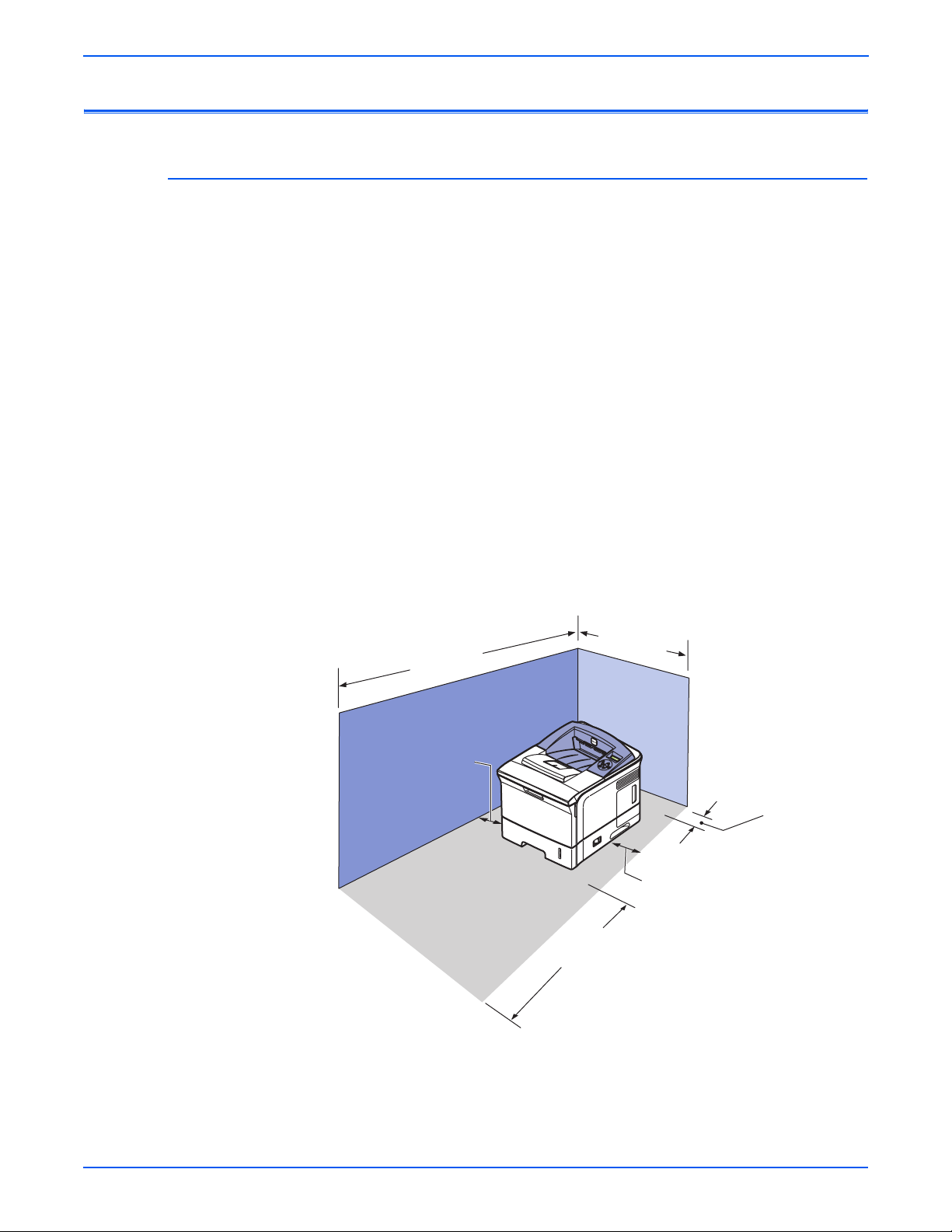
Printer Specifications
Printer Location and Clearance
Place the printer in a dust-free area where the temperature range is 50
degrees F to 89 degrees F (10 degrees C to 32 degrees C) and the relative
humidity range is between 20% to 80%.
■ Place the printer in an area where there is adequate space for ventilation,
operation, and servicing. See the clearance graphic below.
■ Do not block or cover the slots and openings on the printer. The printer
can overheat without adequate ventilation.
■ For altitudes under 2,050 meters (6,726 feet), use the Low Altitude
setting. For altitudes over 2,050 meters (6,726 feet), use the High Altitude
setting.
■ Do not place the printer near a heat source.
■ Do not place the printer in direct sunlight.
■ Do not place the printer in line with the cold air flow from an air
conditioning system.
■ Place the printer on a level, solid surface with adequate strength for the
weight of the printer.
596 mm
1255.6 mm
(24.6 in.)
(49.2 in.)
100 mm
(4 in.)
320 mm
(12.6 in.)
100 mm
(4 in.)
482.6 mm
(18.8 in.)
s3600-003
1-6 Phaser 3600 Printer Service Manual
Page 24

Printer Physical Specifications
Physical Dimensions and Weight
General Information
Item Specification
Packaging
Dimen
(W*D*H)
Net Dimension
(W*D*H)
Toner Dime n s ion
(W*D*H)
Weight SET with 10K toner
Functional Specifications
sion
Packing Dimension w/o
option tray
Net Dimension w/o Option
y
Tra
Net Dimension with Option
Tra
y
Toner 314 x 225 x 116 mm
Toner Packing 368 x 286 x 169 mm
cartri
ge
d
SET w/o toner cartridge 15.46kg (34.06lb)
Consumable toner
cartrid
ge
Set + Consumables 19.15 kg (42.2lb) with 10K toner
Packing Weight 22.46kg (49.50lb)
518*566*568mm
(20.4"*22.3"*22.4")
396*453*353mm
(15.6"*17.8"*13.9")
396*453*501mm
(15.6"*17.8"*19.7")
17.30kg (38.14lb)
10K : 1.85kg (4.08lbs) 20K :
2.06kg (4.54 lbs)
cart.
Print Operability
Characteristic Specification
Printing process Non-Impact Electrophotography
Color medium Monochrome
Resolution / Addressability True 600 x 600 dpi
Addressable 1200 x 1200 dpi
Operating Modes Standby Mode: Pr
prints in less than 9 seconds.
Sleep/ Low Power/ Power Saver Mode: 31
nds from completion of a print.
seco
Continuous Operating Printing
Sp
eed (ppm = pages per
minute)
First Print-Out
(in seconds)
Warm-Up Time Power-on Boot: 40 seconds or less
Letter:
Up to 40 ppm
A4:
Up to 38 ppm
10 seconds or less
int engine capable of making
Phaser 3600 Printer Service Manual 1-7
Page 25

General Information
Print Quality
Property Characteristic Specification
Resolution Normal Up to 1200 x 1200 dpi effective output
Line Width @ 600dpi
Line Width @ 1200dpi
Dot Diameter @ 600dpi
Dot Diameter @ 1200dpi
RET Yes
Halftone (Gray Scale) 256 levels
Blackness >1.20
Homogeneity of Halftone at five points on page must be 0.1
Halftone 20 % = 0.17 50 % = 0.49 80 % = 0.91
Printable Area Letter 208 x 271 mm
A4 200 x 289 mm
Non-Printable Area Envelope 10mm(0.4") from edge(Top/Bottom/Left/Right)
Other Media 4mm(0.16") from edge(Top/Bottom/Left/Right)
Toner Fixing Black (100% Solid) 80%
Halftone 70%
Magnification Horizontal (applied to
17
m length)
7.8m
Vertical (applied to
241.3m
m length)
Printing Skew Tray 1 (MPT)
Tray 2
< 1.0 mm (0.04 ) ( 0.5 % )
< 3.0 mm (0.12 ) ( 1.2 % )
< 1.5 mm (0.06 ) Simplex & Horizontal
< 2.0 mm (0.08 ) Duplex & Horizontal
< 2.0 mm (0.08 ) Simplex & Vertical
< 2.5 mm (0.10 ) Duplex & Vertical
< 1.5 mm (0.06 ) Simplex & Horizontal
< 2.0 mm (0.08 ) Duplex & Horizontal
< 2.0 mm (0.08 ) Simplex & Vertical
< 2.5 mm (0.10 ) Duplex & Vertical
Optional Tray 3
1-8 Phaser 3600 Printer Service Manual
< 2.0 mm (0.08 ) Simplex & Horizontal
< 2.5 mm (0.1 ) Duplex & Horizontal
< 2.5 mm (0.10 ) Simplex & Vertical
< 3.0 mm (0.12 ) Duplex & Vertical
Page 26

Electrical Specifications
Power Rating and Line Voltages
Characteristic Specification
Primary line voltages 110 - 127 V Printer - (100 - 135 V) 13 amp circuit
General Information
220 - 240 V Printer - (180 - 264 V) 7-8 amp circuit
Primary line voltage
ncy range
freque
Power consumption Printing: 550 Watts (average)
Environmental Specification
Operating Environment
Characteristic Specification
Optimal Temperature 10 - 30 degrees C (50-60 degrees F)
Optimal Humidity 20% - 80% Relative Humidity
Altitude
Operating
Low Altitude Setting
High Altitude Setting
Transportation
Acoustic Noise
Idle
Printing
100 - 135 V Printer - 50/60 Hz + 3 Hz
220 - 240 V Printer - 50/60 Hz
Sleep: under 10 Watts
0 - 2,500 meters (8,200 ft.)
0 - 2,050 meters (6,726 ft.)
2,050 - 2,500 meters (6,726 - 8,200 ft.)
0 - 6,092 meters (20,000 ft.)
35.0db or less
49.0db or less
+ 3 Hz
Acoustic Characteristic Mode Specification
Printing Simplex from Tray1 Less than 56.0 dBA
Simplex from MP Less than 56.0 dBA
Simplex from SCF Less than 59.0 dBA
Duplex from Tray1 Less than 59.0 dBA
Measurement Standby Less than 35.0 dBA
Warm up Less than 50.0 dBA
Maximum Less than 60.0 dBA
Phaser 3600 Printer Service Manual 1-9
Page 27

General Information
Media and Tray Specifications
Media Tray Capacity
Property Media Specification
Input Size Max Custom Paper (W*H) 216 x 356 mm (8.5" x 14")
Min Custom Paper
(W*H)
Input Capacity Standard 500-sheet Cassette Tray/100-sheet Multi
Maximum 1 to 100 sheets
Output Capacity Face-Down Capacity 250 sheets
Face-Up Capacity 100 sheets
Output Full sensing Yes (Paper Outbin Full Sensor)
Output path change Face Up/Down controlled manually by
Multi-Purpose
Tra
y
Plain Paper Capacity 100 sheets
Envelope Capacity 10 sheets
Card Stork Capacity 10 sheets
Labels Capacity 25 sheets
Transparencies
Capaci
ty
Media sizes A4/A5/A6/Letter/Legal/Oficio/Folio/
76
x 127 mm (3.0" x 5.0") (>105g)
Purpose T
op
50
Executi
No.10/DL/C5/C6
ray @75g
ng rear cover
eni
sheets
ve/ISO B5/JIS B5/3"x5"/Monarch/
Media type Transparencies/Envelopes/Labels/Card
stock
Media weight 16~43lb (60 to 163g
Sensing Paper Empty Sensor
Standard
Cassette Tr
1-10 Phaser 3600 Printer Service Manual
ay
Capacity 500 sheets
Media sizes A4/A5/Letter/Legal/Executive/Folio/
Ofic
io/ISO B5/JIS B5
Media types Plain paper
Media weight 16~28lb (60 to 105g)
Sensing Paper Empty Sensor and Paper Size
S
nsor
e
Page 28

Media Tray Capacity
General Information
Optional Cassette
Tray
Duplex Supporting Optional
Media Input Size/Weight
Source Media Types Media Sizes Media Weights
Tray 1 Paper, Envelope,
Tray 2 Paper, Cardstock
Capacity 500 sheets@75g
Media sizes A4/A5/Letter/Legal/Executive/Folio/
Oficio
/ISO B5/JIS B5
Media types Plain paper
Media weight 16~28lb (60 to 105g/)
Sensing Paper Empty Sensor
Media sizes A4/Letter/Legal/Folio/Oficio
Media types Plain paper
Media weight 20~24lb (75 to 90g )
A4, Letter, Legal, Folio,
P
per Labels,
a
Transparency.
Min: 76 mm x 127
mm
(3 in. x 5 in.)
Max: Legal
Executive, ISO and JISB5, A5
A4, Letter, Legal, Folio,
O and JISB5, A5,
ve, IS
Executi
A6, Statement Monarch, COM
10, C5, DL, 3” x 5”
16 lb. ~ 28 lb.
(60 ~ 176 gsm)
16 lb. ~ 43 lb.
(60 ~ 105 gsm)
65# Cover
Tray 3 Paper A4, Letter, Legal, Folio,
ve, ISO and
Executi
Duplex Paper A4, Letter, Legal, Folio 20 lb. ~ 24 lb.
Media Print Speed
Property Mode Specification
Speed Simplex Up to 38 ppm in A4
Duplex
First-Page Output Time
(FPOT)
Warm Up Time from sleep/power save mode Less than 31 sec
from standby Less than 9 sec
from sleep/power save mode Less than 40 sec
from cold status Less than 49 sec
from cold status Less than 40 sec
JISB5, A5
16 lb. ~ 28 lb.
(60 ~ 105 gsm)
(75 ~ 90 gsm)
(40 pp
m in Letter)
26 ipm in A4 (27
ip
m in Letter)
(Letter A4 Folio
Of
icio Legal)
Phaser 3600 Printer Service Manual 1-11
Page 29

General Information
Media Print Speed
Toner save setting unit SWS Support
PSU Support (30%)
LUI(Local UI) Support(UI2.0)
Duplex Print Simplex Support
Manual Duplex N/A
Duplex Optional
1-12 Phaser 3600 Printer Service Manual
Page 30

Theory of Operation
In this chapter...
■ Phaser 3600 Operational Overview
■ Printer Paper Path
■ Printer Controls
■ Sensor Functions
■ Printer Controls
Chapter
2
Page 31

Theory of Operation
Phaser 3600 Operational Overview
Summary of the Printing Process
The Phaser 3600 Laser Printer is a desktop monochrome laser printer,
applying the principals of an electrophotographic system to place a
monochrome image onto the print media. The system contains a drum and
developing unit which places the toner image onto print media producing
monochrome prints through the transfer unit.
The printing process is composed of the following:
Charging: T
VDC by the high voltage power supply (HVPS). The charge roller is kept in
contact with the drum surface to provide a uniform negative charge of
approximately -800 VDC on the drum surface as it rotates at a constant
speed.
Exposure: T
image data from the Main board. The laser beams are directed onto the drum
surface through a system of mirrors and lenses. A rotating polygonal mirror
causes the laser beams to scan the drum surface from end to end (axially) as
it rotates. The beams are turned on to print a pixel and off when no printing is
required. The negative charge on the drum surface is reduced to
approximately -250 VDC at each point where the energized laser beam
strikes, to form an invisible electrostatic latent image on the drum surface.
Development: N
applied to the supply roller and are then applied to the developer roller in a
even lay er controlled by the metering blade. The developer roller turns against
the drum and the toner particles are attracted to the relatively positive latent
image. The toner forms a visible image on the drum surface.
Pre-Clean: T
drum lowering the surface potential and thereby providing enhanced transfer
efficiency.
Transfer: Th
media using the voltage supplied by the Transfer Roller. The conductive
Transfer Roller receives a high positive voltage (approximately +1000 VDC)
from the HVPS that puts it at a higher potential than the drum. Since the
Transfer Roller is located behind the print media, the toner image is attracted
to the high potential and deposits on the surface of the print media.
Fixing: T
the
image, the print media goes through the Fuser where it passes between a
pressure roller and the Heat Roller. The toner is fused onto the print media by
the combination of heat and pressure.
The Heat Roller is heated by a heat element. The roller surface temperature is
ec
ted by a Thermistor. The information is fed back to the heater control to
det
maintain a surface temperature of 185º C during printing and 145º C during
standby. If the thermostats detect a Fuser overheat condition, it disconnects
AC power to the Fuser.
Cleaning: A
inside the cartridge removes any remaining toner particles from the drum.
h
he finished toner image is impermanent and easily smeared. To fix
fte
e charge roller is negatively charged at approximately -1400
h
e Laser Scan Unit (LSU) emits laser beams in response to
tively charged toner particles from the toner hopper are
ega
h
e pre-transfer Lamp exposes the developed surface of the
e finished toner image on the drum is transferred onto the print
r the image is transferred to the print media, a cleaning blade
2-2 Phaser 3600 Printer Service Manual
Page 32

Print Cartridge and Print Modes
Print Cartridge
The Print Cartridge receives image data in the form of pulsed laser light from
the Laser Scan Unit (LSU) and creates the image via the xerographic
process. The Print Cartridge contains the following components:
■ Charge Roller
■ Drum
■ Developer Roller (D/R)
■ Supply Roller (S/R)
■ Metering Blade
■ Cleaning Blade
Theory of Operation
Print Modes
Cleaning Roller
-1.5 ~ -1.30KV
Charging Roller
Cleaning Blade
LSU
0.20 mW
Zener Diode
-100V
-400 ~ -500±20V
V
: -680V
0
V
: -620V
L
OPC Drum
Transfer Roller
Doctor Blade
Developing
Roller
Max. +4.2kV
-500 ~
-600±20V
Supply Roller
PTL
s3600-004
The Phaser 3600 Laser Printer provides two print modes:
1. Draft mode: Uses a combination of reduced toner output and the lowest
resolution (300 x 300 dpi) to extend print cartridge life.
2. Enhanced mode: Used for printing on plain paper with an addressable
resolution of 1200 x 1200 dpi.
Phaser 3600 Printer Service Manual 2-3
Page 33

Theory of Operation
Printer Paper Path
Paper Path Components
The diagram below shows the paper path and identifies the major
components of the printer. The simplex paper path is shown in red and the
duplex path is shown in light red.
Registration Sensor
Tray 1 Pick Roller
Tray 1
No Paper
Sensor
Feed 2 Idler
Feed 2 Roller
Retard Roller
Feed 1 Roller
Tray 2
Pick Roller
Retard Roller
Tray 3 Feed Roller
Imaging Drum (OPC)
Idler
Registration Roller
Tray 3 No Paper Sensor
Tray 3 Pick Roller
Exit Roller
Heat Roller
Tray 2 No Paper Sensor
Exit/Duplex Roller
Idler
Fuser Exit Roller
Fuser Exit Sensor
Pressure Roller
Transfer
Roller
Duplex
Rollers
Duplex Sensor
s3600-085
Media that meets printer specifications can be fed from Tray1 (MPT) and Tray
2, or the Optional Tray 3. If you use thick paper with a weight of more than 105
gsm (60 lbs), you must insert the paper into T ra y 1 (MPT) and select the paper
type. Paper will exit the printer to the face down top tray. A door at the rear of
the printer provides access for jam clearance.
All major components of the printer are explained in greater detail under
i
nter Controls on page 2-10.
Pr
2-4 Phaser 3600 Printer Service Manual
Page 34

Duplex Paper Path
Paper Feed Sequence
Paper Transport
Theory of Operation
When 2-sided printing is selected, side two is printed first, the image being
printed is the first image. After the first image prints, the paper is reversed and
is fed through the duplexer and back up to the feed roller with side one
positioned for printing with the second image.
When the Main Board is ready to feed paper, it energizes the paper feed
solenoid. The solenoid armature releases the clutch and the Pick-Up Roller
makes one revolution. This drives the paper to the Feed Roller and the Retard
Roller. The Feed Roller and Retard Roller drive the paper to the Registration
Assembly, which in turn drives the paper towards the transfer area. Before
arriving at the transfer area, the paper actuates the Feed Sensor.
The Registration Assembly continues to drive the paper into the transfer area,
where the image is transferred from the drum to the paper.
After the image transfers, the paper continues to the Fuser Assembly for the
ng the process. In the Fuser Assembly, the Heat Roller is heated by a heat
fusi
element and the paper passes in between the Heat Roller and the pressure
roller, where toner melts onto the paper to form a permanent image. The
temperature of the heat roller is monitored by a Thermistor that sends signals
to the Main Board.
The Fuser Assembly drives the paper into the Exit Rollers, which drive the
er
into the output tray . When printing the first side of a duplex print job, the
pap
drive direction is reversed when the Exit Sensor is actuated. Paper is then
directed into the Duplex Unit for printing on the second side.
Paper Feed Drive
The drive for all rollers is provided by the Main Drive Motor and a series of
drive gears. The Main Motor is used for paper feed, fusing, and the duplex/exit
roller reversal for 2-sided printing. When the main motor turns, all the paper
path components also turn except the Pick-Up Roller. The Pick-Up Roller
assembly moves the paper along the path with the Feed Solenoid. There is a
separate Developer Motor for the Print Cartridge.
Phaser 3600 Printer Service Manual 2-5
Page 35

Theory of Operation
C
Print Engine Assemblies
The print engine assemblies include the following:
■ Image Processing and the Main Board
■ Laser Scan Unit
■ Main Drive Assembly
■ Feed assembly Process and Components
■ Transfer Roller Assembly
■ Fuser Assembly
Image Processing Assembly and Main Board
The Main Board receives image data from the host computer, converts it to a
bitmap image, and then transfers the image to the Laser Scan Unit (LSU).
The Main Board combines the Image Processor and Engine Control
tions. It contains a 32 bit RISC processor and comes with a standard
func
memory capacity of 64 Mbytes of RAM and 4 Mbytes of flash memory. The
board provides one expansion slot that allows available memory to be
expanded up to 512 Mbytes with two 256Mbyte RAM DIMM.
ontrol Panel (CN16)
Cover Open (CN26)
Duplex Solenoid (CN11)
Laser Unit (CN9)
Developer
Thermistor (CN8)
Motor (CN20)
PTL (CN21)
Toner Sensor Board (CN6)
Rear Fan (CN4)
LVPS (CN19)
Ethernet (CN1)
Power (CN22)
USB (CN2)
Duplex (CN17)
Main Motor
(CN18)
Exit Sensor
Parallel Port
(CN3)
(CN23)
Joint Board
(CN24)
Optional
3rd Tray
(CN25)
RAM DIMM 1 (CN14)
RAM DIMM 0 (CN12)
s3600-077
2-6 Phaser 3600 Printer Service Manual
Page 36

Laser Scan Unit (LSU)
The Laser Scan Unit (LSU) is the core element of the image production
process. The LSU receives video data from the controller on the Main Board
and converts the data to an electrostatic latent image on the OPC (Organic
Photo Conductor) drum. The laser beam exposes the OPC drum under
direction of the controller. The controller also turns the drum synchronously
with a polygon mirror within the LSU. The OPC drum also turns in relation to
the speed of the paper feed process. An /HSYNC signal is created when the
laser beam from LSU reaches the end of a polygon mirror, and the signal is
sent to the controller.
The controller detects the /HSYNC signal to adjust the vertical line of the
age
im
image data is sent to the LSU to adjust the left margin of the media.
Motor Drive Assemblies
The Motor Drive Assemblies include the Main Motor and the Developing
Motor. Under control of the Main Board, the Main Motor Drive is a power
delivery unit. Through a series of gears, it supplies the power to the paper
feed components, the fusing unit, and the distributing unit. For the duplex
process, the Main Motor energizes a solenoid to change paper direction.
By gearing, the main motor drives the rollers such as Feed Roller, developing
oll
er, fuser roller, and Exit Roller. In addition, a step motor controls the
r
acceleration of the drive gearing.
The Developing motor also drives gears that, in turn, drive components used
in the
Theory of Operation
on paper. That is, after the controller detects the /HSYNC signal, the
image development process.
Feed Assembly Process and Components
The Feed assembly process and components consists of:
1. Separation process
parates the paper from the friction pad mounted to the center of the
Se
cassette and applies a Retard Roller which uses a spring clutch. A
separate Feed Roller then uses an electronic clutch to control driving
power.
2. Center Loading Process
A center loading method applies 'friction pad separation’, which means
that a software process first detects paper (even though there is a paper
sensor). After the initial detection, the Paper Size Sensor determines
paper size (see “Paper Size Sensor” on page 2-16).
Both the side guide and the rear guide can be adjusted for various types
of papers from A5 to legal size paper. The process also includes a paper
arranging function and a display function displays the amount of paper
remaining. In the front side of the tray, there is a paper level indicator.
3. Paper Pick-up Process
Functions include a paper pickup function, paper feeding function, and the
removal of electronic static.
Phaser 3600 Printer Service Manual 2-7
Page 37

Theory of Operation
Transfer Roller Assembly
4. Miscellaneous Paper Functions
A paper arrangement function uses a stopper roller and a weight without
an electric actuator. It also includes an additional paper separating
function, a driving control function, and a multi feeding prevention
function. The Feed Roller transfers paper along the paper path and is also
part of jam detection.
The transfer subsystem consists of the Pre-transfer Lamp (PTL) and the
Transfer Roller . The PTL exposes the drum surface after the latent image has
been developed to lower surface potential of the drum. This provides
enhanced transfer efficiency.
The Transfer Roller provides a high positive potential on the back of the print
. This potential attracts the negatively charged toner image from the
media
drum and deposits it on the surface of the print media.
The transfer voltage is controlled by PWM (Pulse Width Modulation). When
the pap
er enters the Transfer Roller, the resistance value of the Transfer
Roller will change due to the surrounding temperature of the printer. If the
temperature changes, a new voltage level is created through an AD converter.
Fuser Assembly
The Fuser Assembly contains the entire Fuser Subsystem and is a field
replaceable unit. The Fuser Assembly contains the following components:
■ Heat Element and Heat Roller :Two quartz lamps operate as the heating
elements, which generate the heat inside the Heat Roller. The Heat Roller
melts the toner so it adheres to the paper.
■ Pressure Roller: Provides pressure on the opposite side of the print
media so the Heat Roller can embed the melted toner in the media.
■ Thermistor: Monitors the surface temperature of the He at Roller. This
information is used to control the heat lamp and thus keep the Heat Roller
at the correct temperature.
■ Thermostat: Prevents overheat damage when unexpected system faults
occur.
2-8 Phaser 3600 Printer Service Manual
Page 38

Duplex and Tray Assemblies
Duplex Assembly
The Optional Duplex Assembly automatically prints on both sides of a sheet of
paper. With the Duplex Assembly, the printer can print A4-sized paper up to
26 inches per minute (IPM) and letter-sized paper up to 27 IPM. The duplexer
also supports the Oficio and Folio paper sizes.
The components of the Duplex unit include a paper transfer function, paper
de
gui
board supporting function.
You can remove a jam at the front of the assembly by merely opening up the
cass
merely open the rear cover.
Tray 2 and Optional Tray 3 Assemblies
Theory of Operation
function, jam removing function, paper sensing function, and main
ette and paper guide. To remove a jam in a rear part of the assembly,
You can increase the paper handling capacity of the printer by installing Tra y 2
or an optional Tray 3. Each tray holds 500 sheets of paper (Cassette is same
size as the Tray1 (MPT). Each tray includes a separate driving mechanism
with the following features:
■ Feeding Method : Cassette Type
■ Feeding Standard : Center Loading
■ Feeding Capacity : Cassette 500 Sheets(75g/ , 20lb Paper Standard)
■ Paper Detecting Sensor : Photo Sensor
■ Paper Size Sensor : Yes
Phaser 3600 Printer Service Manual 2-9
Page 39

Theory of Operation
Printer Controls
Paper Size Control
The paper size selection for Tray 2 and Tray 3 is set by moving the paper
guide in the tray. This in turn sets the plastic “fingers” on the side of the paper
tray to a specific postion.The position of the “fingers” activates the correct
combination of the three paper size switches, located in each paper tray slot,
for the selected paper size. Additionally, the back of the tray must be pulled
down in order to select the two largest sizes; US Folio and Legal. Not all sizes
can be used in bo th tr a ys . See “Media and Tray Specifications” on page 10 for
a complete listing of the media types for each tray. Additional media types can
ed in Tray 1 (MPT). After inserting the media in Tray 1, use the Control
us
be
Panel controls to select the media type.
Paper Size Switch
Paper Size
SW1 SW2 SW3
LEGAL 14" ON ON OFF
US FOLIO (LEGAL 13”) OFF OFF OFF
A4 OFF ON ON
LETTER ON OFF OFF
EXECUTIVE OFF ON OFF
B5 ON OFF OFF
B5, JIS-B5 OFF OFF ON
A5 ON ON ON
No Tray OFF OFF OFF
Automatic Paper Pick Control
The default paper pick selection at power ON is T ra y 2, Auto-Select ON is also
default. If the default tray is empty, the printer will automatically switch to any
other tray that contains paper unless Auto-Select is set to OFF.
2-10 Phaser 3600 Printer Service Manual
Page 40

Laser Scan Unit (LSU) Control
The Laser Scan Unit receives the bit-mapped image data from the Main
Board and uses that information to turn the laser beam on and off as required
to correctly expose the drum. Image data transfer from the Main Board is
controlled by a synchronization signal from the LSU so the vertical scanning
line is synchronized with the printed page. The LSU contains the following
components:
■ Laser Diodes: Generates the laser beams.
■ Rotating Polygon Mirror: Scans the laser beam across the drum, axially.
■ Beam Detector: Synchronizes the left margin.
■ Optical Lens System: Focuses the laser beam onto the surface of the
drum.
■ Mirrors: Reflect the laser beam onto the surface of the drum.
Laser Light Intensity Control
Theory of Operation
Toner Control
Image data is transmitted to the laser diode in the Laser Scan Unit as digital
signals. The laser diode converts the image data from digital signals to optical
signals; data expressed by blinking laser beams. The Laser Scan Unit
monitors the output to determine if variations in the light intensity from the
laser beam, variations in the optical system (such as mirrors and lenses), or
variations in drum sensitivity are preventing the system from obtaining a
proper electrostatic image and, if necessary, adjusts the light intensity to
attain a stable electrostatic image.
Error Description Error Message
Polygon Motor
o
r
Err
Hsync Error The polygon motor speed is steady,
Print Cartridge installation and Toner Le vel are detected by the Print Cartridge
Interconnect Board and the associated signals are supplied to the Main
Board. The CRUM not only detects cartridge presence, it also determines
whether it is a genuine Xerox cartridge. When the toner remaining falls to
15%, the printer displays a low toner message on the Control Panel display.
The polygon motor speed cannot
obtain a steady state.
but t
he Hsync signal is not generated.
Laser Failure
Laser Failure
Phaser 3600 Printer Service Manual 2-11
Page 41

Theory of Operation
Fuser Temperature Control
During Fuser temperature control the printer’s target temperature is set. The
Heat Roller surface temperature is controlled to match the target temperature
by turning the heat element ON/OFF. The Heat Roller surface temperature is
detected by a Thermistor. If the Thermistor shows that the temperature is
higher than the target, the heat element is turned OFF. If the detection result
is low, the heater lamp is turned ON. The fuser control circuit keeps the Fuser
temperature at 185º C during printing and at 145º C during standby.
■ When the power voltage for the printer is too high or too low, the Fuser is
stopped to protect the Fuser.
■ When the AC voltage is not applied to the Fuser control circuit, the fuser
will not work and a Fuser Low Heat Error will occur.
■ When the temperature of the Fuser is too high, an “Engine Overheat”
error occurs if the cooling operation is insufficient
Error Description Error Message
Open Heat Error When warming up, the Fuser has been
r than 60 degrees C for over 35
lowe
seconds.
Low Heat Error Stand-by:
■ Lower than 130 degrees C for over
10 seconds.
■ Printing:
■ Up to 2 consecutive pages: Lower
than 155 degrees C for over 7 seconds.
■ From 3 consecutive pages: Lower
than 25 degrees C than the fixed fusing
temperature over 7 seconds.
Over Heat Error Temperature is higher than 230 degrees
C o
ver 10 seconds.
Fuser Fai
lure
Engine Low Heat Error
Engine Over Heat
Error
2-12 Phaser 3600 Printer Service Manual
Page 42

Sensor Functions
Sensor Types
The types of sensors used vary with function. In general, there are three types
in use:
Photo Sensors
Two types of photo sensors are used, photo-reflective and photo-receptive.
Photo-reflective sensors use light reflected back from an object to detect its
presence. Photo-receptive sensors use an actuator or the object itself to block
the light path to detect an object or condition.
Photo-reflective sensors have the light emitter and light receiver aligned on a
ng
si
being reflected back and Low (< +.3 V) when it isn’t.
Photo-receptive sensors consist of a LED in one arm of a U-shaped holder,
and a p
nothing is between the arms of the sensor, light falls on the photo-receptor
sending the signal High. If the light is interrupted, the photo-transistor goes
Low.
Theory of Operation
le surface. Output of the photo-receptor is High (> +4.5 V) when light is
hoto-transistor in the other arm. When the sensing area is vacant,
Actuator
s3600-133
Phaser 3600 Printer Service Manual 2-13
Page 43

Theory of Operation
Microswitches
Microswitches are used primarily as paper size sensors and cover interlocks.
They are in a normally open state, and close when actuated. A bank of
microswitches is used to detect paper size in the universal trays.
Microswitches also employ hooks or catches for retention in the bracket or
frame.
Actuator
Button
Thermistors
Contact
Thermistors have a known value of resistance whose value varies with
temperature. Used primarily in the Fuser for temperature sensing.
Blade
s3600-134
2-14 Phaser 3600 Printer Service Manual
Page 44

Sensors in the Paper Path
Sub T
The following illustration shows the general physical location of the specified
sensor. Not all the sensors in the illustration have replaceable part numbers.
The text topics following the illustration describe those sensors that have
associated part numbers.
and Sensor
oner Low Board
Theory of Operation
Output Tray Full Sensor
Fuser Exit Sensor
Fuser Interlock Switch
Paper Size Sensor
Paper Tray
Empty Sensor
Tray 1(MPT)
Feed Sensor
Tray 2 Paper
Empty Sensor
Tray 3 Paper
Empty Sensor
Paper Tray Empty Sensor
Media supply is monitored by the Paper Tray Empty Sensor. When any paper
tray runs out of paper, the sensor will send a signal to the Main Board, the
control panel LED will blink red, and the message will display on the control
panel identifying which tray “No Paper in Tray {2|3}” is empty.
Cover Open
Interlock Switch
Duplex Sensor
Tray 1(MPT)
Paper Empty
Sensor
Tray 2 Feed
Sensor
Tray 3 Feed
Sensor
s3600-086
Tray 1 (MPT) Paper Empty Sensor
The Tray 1 (MPT) paper empty sensors monitors paper from Tray 1. If Tray 1 is
selected and no paper is available, a message appears on the control panel. If
there is no paper in Tray 2 or Tray 3 and the printer is in auto-select mode, the
printer will look for paper in all the trays and report “No Paper in Tray 1”.
Tray 1 (MPT) Feed Sensor
The Tray 1 (MPT) Feed Sensor has two purposes. First, it monitors paper
movement. If the paper takes too long getting to the sensor, or it stays at the
sensor location too long, the Main Board will shut down the machine, the
control panel LED will blink red, and a “Jam” error message will display on the
control panel.
Phaser 3600 Printer Service Manual 2-15
Page 45

Theory of Operation
Secondly , the signal generated by the sensor tells the Main Board that the
paper is almost at the transfer area and it is time to start the xerographic
process. It is important that the leading edge of the paper enters the transfer
area at the same time as the leading edge of the developed image on the
drum.
Paper Size Sensor
The Paper Size Sensor detects the presence of paper and monitors a paper
size plate consisting of three sensitive metal tabs in the paper path.
Depending on the size of the paper, one or more of these tabs will send a
signal to the Main Board with the information needed to determine the paper
size. For information regarding the paper size combinations, see “Paper Size
Control” on page 2-10.
Outbin Tray Full Sensor
The Outbin Tray Full Sensor detects when the output bin is full and can no
longer accept more paper from the exit section of the paper path. When the
Main Board detects this sensor, it sends an “Output Bin Full” message to the
control panel.
Fuser Exit Sensor
The Fuser Exit Sensor monitors paper exit and detects the “Jam at Exit” error
if the paper takes too long getting to the sensor, or it stays at the sensor too
long. At this point the Main Board will shut down the printer, the Control Panel
LED will blink red, and a “Jam at Exit” error message will display on the
Control Panel. The signal from the Fuser Exit Sensor is also used to control
paper feed to the Duplex Unit for duplex print jobs.
Cover Open Interlock Switch
The Cover Open Interlock Switch detects whether the top cover is open or
closed. When the top cover is open the “Close Top Cover” message displays
on the Control Panel.
Duplex Sensor
The Duplex Unit slides into the rear of the printer above Tray 2. The Main
Board senses the presence of the Duplex Unit and paper in the Duplex unit
through the Duplex connector. As paper leaves the Fuser Assembly and is
picked up by the Exit Rollers, the drive direction is reversed to send the paper
into the Duplex Unit. As the paper leaves the Duplex Unit, it activates the
Duplex Sensor within the unit. This activates the Feed Roller to position the
paper for printing on the second side of the paper.
2-16 Phaser 3600 Printer Service Manual
Page 46

Power Supplies
High Voltage Power Supply (HVPS)
Theory of Operation
The HVPS section generates and supplies the following voltages:
■ Transfer Voltage
■ Charge Voltage
■ Bias Voltage
■ Supply Voltage
The Bias, Supply, and Charge voltages are used by the Print Cartridge.
The power distribution section receives AC voltage and creates the required
DC outp
uts (3.3 VDC, 5 VDC, and 24 VDC) to power the printer components.
It also supplies AC voltage to the Fuser Assembly.
CON02
CON01
CON03
CON05
CON06
CON04
s3600-078
Phaser 3600 Printer Service Manual 2-17
Page 47

Theory of Operation
Switching Mode Power Supply (SMPS)
The SMPS is mounted on the bottom of the printer and is the main power
source of the entire system. It converts the AC input line into two main output
channels: 3.3. volts DC and 24 Volts DC. The SMPS then provides these
output channels to various components throughout the system in a switching
mode as instructed by the Main Board.
The SMPS also drives the AC heater unit, which supplies controlled current
v
els to the Fuser assembly as an independent module.
le
DEVE
SUPPLY
FUSER
MHV
OPC
THV
CN1
CN2
CN4
CN3
s3600-079
2-18 Phaser 3600 Printer Service Manual
Page 48

Error Messages
In this chapter...
■ Troubleshooting Overview
■ Service Diagnostics
■ Service Diagnostics Menu Map
■ Troubleshooting Error Messages
Chapter
3
Page 49

Error Messages
Troubleshooting Overview
Using the Troubleshooting Procedures
This section covers troubleshooting procedures for the Phaser 3600 Laser
Printer. When an error first occurs, record the error message and code and
then cycle power to the printer to see if the error recurs.
To troubleshoot image-quality problems, see “Image-Quality Troubleshooting”
on page 5-9.
1. Each Step in a Troubleshooting Procedure instructs you to perform a
certain action or procedure. The steps are to be followed sequentially until
the problem is fixed or resolved.
2. The Actions and Questions box contains additional information and/or
additional procedures you must follow to isolate the problem.
3. When a procedure instructs you to test a component using service
diagnostics, see the “Service Diagnostics Menu Map” on page 3-3 for the
detailed steps and functions for testing parts of the printer.
4. The action is followed by a question. If your response to the question is
“Yes”, then follow the instructions for a “Yes” reply. If your response to the
question is “No”, then follow the instructions for a “No” reply.
5. Troubleshooting Procedures may ask you to take voltage readings or test
for continuity at certain test points within the printer. For detailed
diagrams, see “Plug/Jack and Connector Locators and Maps” on
page 9-3 for complete information on test point locations and signal
names.
6. Troubleshooting Procedures often ask you to replace a printer
component, see “Service Parts Disassembly” on page 7-1 for detailed
steps in removing and replacing all major components of the printer. The
“Parts List” on page 8-1 details the location, quantity , and part number for
all spared printer components.
3-2 Phaser 3600 Printer Service Manual
Page 50

Service Diagnostics
The printer has built-in diagnostics to aid in troubleshooting problems. The
Service Diagnostics Menu provides a means to test sensors, motors,
switches, clutches, fans and solenoids. Diagnostics also contain built-in test
prints, cleaning procedures, printer status and some NVRAM access.
Service diagnostics are to be executed through the control panel by a certified
r
vice technician only.
se
Service Diagnostics Menu Map
Entering Service Diagnostics
Error Messages
1
2
s3600-113
1. Turn the printer power OFF.
2. While holding down the ‘OK’ button (1), turn the printer back ON (2).
Note
Refer to the “Diagnostic Test Menu Map” on page 3-5 to see the
description of all component tests.
Phaser 3600 Printer Service Manual 3-3
Page 51

Error Messages
Service Diagnostic Control Panel Button Descriptions
1
5
1. Cancel Button
2
6
2. Return Button
3. On-line/Data/Error LED
4. Menu Button
3
4
7
8
5. Status/Error Messages
and Menus
6. Up Arrow Button
7. OK Button
8. Down Arrow Button
The alphanumeric display provides status messages and control panel
menus.
Diagnostic Control Panel Buttons
Button Function
BACK Returns to the prior higher level menu structure, if
able.
avail
Stops the actively running test.
s3600-002
CANCEL Terminates the current test.
MENU Cycles through all of the top level menu items.
UP Scrolls up one menu item within a menu list. This control
does not
Used to increment values in tests requiring user input.
DOWN Scrolls up one menu item within a menu list. This control
does not
Used to increment values in tests requiring user input.
OK Enters the highlighted menu. Executes the current test
ite
Used to select the value entered by the user.
‘wrap’.
‘wrap’.
m.
3-4 Phaser 3600 Printer Service Manual
Page 52

Diagnostic Test Menu Map
Not
e
For definitions of Acronyms and Abbreviations listed in the Diagnostic
Menu Map below, refer to the Appendix (page A-2).
Diagnostic Menu Map Options
Main Menu Sub Menu Description/Function Control Panel
Error Messages
Display
Cover Status
est
0)
(T
Top Cover If the cover is opened, "Open"
message will be displayed and if
not, "Closed" displayed.
Tray 1
Cassette
*(T1 thru T3
fer to Tray
re
1 thru Tray3
respectfully.
T4 is not
supported
Tray 2
Cassette
Tray 3
Cassette
Fuser Door If the Door is opened, "Open"
If the Tray is opened, "Open"
age w
mess
not, "Closed" displayed
If the Tray is opened, "Open"
message w
not, "Closed" displayed
If the Tray is opened, "Open"
message w
not, "Closed" displayed
message w
not, "Closed" displayed.
ill be displayed and if
ill be displayed and if
ill be displayed and if
ill be displayed and if
Top Cover
[Closed]/[Open]
Tray 1 Cassette
Tray 2 Cassette
Tray 3 Cassette
Fuser Door
[Closed] [Open]
Phaser 3600 Printer Service Manual 3-5
Page 53

Error Messages
Diagnostic Menu Map Options
n
Menu Sub Menu Description/Function Control Panel
Mai
Display
Sensor
Status
(Test 1)
Registration
Sensor
T1Feed
or
Sens
T2 Feed
or
s
Sen
T3 Feed
or
Sens
T4 Feed
or
s
Sen
Exit Sensor The first value lists normal display
The first value lists normal display
before touching the sensor, and the
second value lists normal display
after touching the sensor.
The first value lists normal display
before touching the sensor, and the
second value lists normal display
after touching the sensor.
The first value lists normal display
before touching the sensor, and the
second value lists normal display
after touching the sensor.
The first value lists normal display
before touching the sensor, and the
second value lists normal display
after touching the sensor.
The first value lists normal display
before touching the sensor, and the
second value lists normal display
after touching the sensor.
ore touching the sensor, and the
f
be
second value lists normal display
after touching the sensor.
Registration
nsor
Se
[Without Paper]
[With Paper]
T1 Feed Sensor
[Without Paper]
[With Paper]
T2 Feed Sensor
[Without Paper]
[With Paper]
T3 Feed Sensor
[Without Paper]
[With Paper]
T4 Feed Sensor
[Without Paper]
[With Paper]
Exit Sensor
[Without Paper]
[With Paper]
DJam 1
or
s
Sen
The first value lists normal display
before touching the sensor, and the
second value lists normal display
after touching the sensor.
DJam1 Sensor
[Without Paper]
[With Paper]
3-6 Phaser 3600 Printer Service Manual
Page 54

Diagnostic Menu Map Options
n
Menu Sub Menu Description/Function Control Panel
Mai
Display
Error Messages
Sensor
Status (cont)
Outbin
Sensor
Bypass
ty
p
Em
T1 Paper
ty
p
Em
T2 Paper
ty
Emp
T3 Paper
ty
p
Em
T4 Paper
ty
p
Em
The first value lists normal display
before touching the sensor, and the
second value lists normal display
after touching the sensor.
The first value lists normal display
before touching the sensor, and the
second value lists normal display
after touching the sensor.
The first value lists normal display
before touching the sensor, and the
second value lists normal display
after touching the sensor.
The first value lists normal display
before touching the sensor, and the
second value lists normal display
after touching the sensor.
The first value lists normal display
before touching the sensor, and the
second value lists normal display
after touching the sensor.
The first value lists normal display
before touching the sensor, and the
second value lists normal display
after touching the sensor.
Outbin Sensor
[Normal] [Full]
Bypass Empty
[Empty][Present]
T1 Paper Empty
[Empty][Present]
T2 Paper Empty
[Empty][Present]
T3 Paper Empty
[Empty][Present]
T4 Paper Empty
[Empty][Present]
T1 PSize0
or
s
Sen
T1 PSize1
or
s
Sen
T1 PSize2
or
s
Sen
T2 PSize0
or
s
Sen
T2 PSize1
or
s
Sen
The first value lists normal display
before touching the sensor, and the
second value lists normal display
after touching the sensor.
The first value lists normal display
before touching the sensor, and the
second value lists normal display
after touching the sensor.
The first value lists normal display
before touching the sensor, and the
second value lists normal display
after touching the sensor.
The first value lists normal display
before touching the sensor, and the
second value lists normal display
after touching the sensor.
The first value lists normal display
before touching the sensor, and the
second value lists normal display
after touching the sensor.
T1 Psize0 Sen
[Low] [High]
T1 Psize1 Sen
[Low] [High]
T1 Psize2 Sen
[Low] [High]
T2 Psize0 Sen
[Low] [High]
T2 Psize1 Sen
[Low] [High]
Phaser 3600 Printer Service Manual 3-7
Page 55

Error Messages
Diagnostic Menu Map Options
Menu Sub Menu Description/Function Control Panel
Main
Display
Sensor
Status (cont)
T2 PSize2
Sensor
T3 PSize0
or
s
Sen
T3 PSize1
or
s
Sen
T3 PSize2
or
Sens
T4 PSize0
or
s
Sen
T4 PSize1
or
s
Sen
The first value lists normal display
before touching the sensor, and the
second value lists normal display
after touching the sensor.
The first value lists normal display
before touching the sensor, and the
second value lists normal display
after touching the sensor.
The first value lists normal display
before touching the sensor, and the
second value lists normal display
after touching the sensor.
The first value lists normal display
before touching the sensor, and the
second value lists normal display
after touching the sensor.
The first value lists normal display
before touching the sensor, and the
second value lists normal display
after touching the sensor.
The first value lists normal display
before touching the sensor, and the
second value lists normal display
after touching the sensor.
T2 Psize2 Sen
[Low] [High]
T3 Psize0 Sen
[Low] [High]
T3 Psize1 Sen
[Low] [High]
T3 Psize2 Sen
[Low] [High]
T4 Psize0 Sen
[Low] [High]
T4 Psize1 Sen
[Low] [High]
Motors
2)
est
(T
T4 PSize2
or
s
Sen
DPX Detect
or
s
Sen
Main Mtr
Fwd
Main Mtr
Slow
Dev Mtr Nor The motor will run on the forward
Dev Mtr
Slow
Duplex Mtr
Fwd
T2 Feed
Mot
or
The first value lists normal display
before touching the sensor, and the
second value lists normal display
after touching the sensor.
The first value lists normal display
before touching the sensor, and the
second value lists normal display
after touching the sensor.
The motor will run on the forward
direction or stop.
T
he motor will run on the forward
direction in half speed mode.
di
rection in normal speed.
T
he motor will run on the forward
direction in half speed.
T
he motor will run on the forward
direction.
The motor will run on the forward
direction or stop.
T4 Psize2 Sen
[Low] [High]
DPX Detect Sen
[Low] [High]
Main Mtr Fwd
[On] [Off]
Main Mtr Slow
[On] [Off]
Dev Mtr Nor
[On] [Off]
Dev Mtr Slow
[On] [Off]
Duplex Mtr Fwd
[On] [Off]
T2 Feed Motor
[On] [Off]
3-8 Phaser 3600 Printer Service Manual
Page 56

Diagnostic Menu Map Options
Main
Menu Sub Menu Description/Function Control Panel
Display
Error Messages
Motors
(Cont.)
Fans
(Test
3)
Clutches/
enoids
Sol
(Test 4)
T3 Feed
Motor
T4 Feed
Mot
or
Fuser Fan The fan will run or stop. Fuser Fan
Fuser Fan
Rdy
SMPS Fan The fan will run or stop. SMPS Fan
SMPS Fan
Rdy
Duplex Fan The fan will run or stop. Duplex Fan
T1 P-up
Clutch
T2 P-up
Clutch
The motor will run on the forward
direction or stop.
The motor will run on the forward
direction or stop.
Check
whether the fan is in the
locked state.
whether the fan is in the
Check
locked state.
The clutch will run or stop. T1 P-up Clutch
T
he clutch will run or stop. T2 P-up Clutch
T3 Feed Motor
[On] [Off]
T4 Feed Motor
[On] [Off]
[On] [Off]
Fuser Fan Rdy
[Ready]
[Not Ready]
[On] [Off]
SMPS Fan Rdy
[Ready]
[Not Ready]
[On] [Off]
[On] [Off]
[On] [Off]
Fuser Ctrl
(Test
5)
T3 P-up
Clutch
T4 P-up
Clutch
Bypass
Clutch
Duplex Sol. The solenoid will run or stop. Duplex Sol.
Fuser Bias The bias will have the previously
Temp
Cont
rol
Fuser Temp The Control Panel displays a digital
Inner Temp The Control Panel displays a digital
T
he clutch will run or stop. T3 P-up Clutch
[On] [Off]
T
he clutch will run or stop. T4 P-up Clutch
[On] [Off]
T
he clutch will run or stop. Bypass Clutch
[On] [Off]
[On] [Off]
Fuser Bias
saved value.
The fuser unit will control the power
for fixing and displaying the current
temperature on the panel. The target
temperature is 160 degrees.
valent [xxx] of the analog value.
ui
eq
equi
valent [xxx] of the analog value.
[On] [Off]
Temp Control
[On] [Off] [xxx]
Fuser Temp
[xxx]
Inner Temp
[xxx]
Phaser 3600 Printer Service Manual 3-9
Page 57

Error Messages
Diagnostic Menu Map Options
Main
Menu Sub Menu Description/Function Control Panel
Display
LSU Ctrl
(Test 6)
Dev Control
7)
(Test
LD Power1 The display shows the previously
saved value.
LD Power2 The display shows the previously
saved val
Laser Motor The motor will run or stop. Laser Motor
Laser Ready When the LSU is ready to print
(l
aser diode ON with a stable motor
speed), the message, “Normal”
displays.
THV Plus
Bias
THV Minus
Bias
DEV Bias The panel displays the previously
DEV AC Bias The panel displays the previously
DEV Vpp
Bias
The panel displays the previously
saved bias value.
T
he panel displays the previously
saved bias value.
saved bi
saved bi
T
he panel displays the previously
saved bias value.
ue.
as value.
as value.
LD Power1
[On] [Off]
LD Power2
[On] [Off]
[On] [Off]
Laser Ready
[Normal] [Fault]
THV Plus Bias
[On] [Off]
THV Minus Bias
[On] [Off]
DEV Bias
[On] [Off]
DEV AC Bias
[On] [Off]
DEV Vpp Bias
[On] [Off]
Test Print
(Test
8)
MHV Bias The panel displays the previously
saved bi
PTL The Pre-transfer Lamp wil
either on or off.
Erase Lamp The lamp will be either on or off. Erase Lamp
TR Cur Read The Control Panel displays a digital
equi
CR Cur
Read
Pattern Print The printer prints a pattern test page
T2 Version Displays Tray 2 version 2.00
T3 Version Displays Tray 3 version 1.00
T4 Version N/A N/A
DPX Version 1.03
The Control Panel displays a digital
equi
into Tray (MPT).
as value.
l be
valent [xxx] of the analog value.
valent [xxx] of the analog value.
MHV Bias
[On] [Off]
PTL
[On] [Off]
[On] [Off]
TR Cur Read
[xxx]
CR Cur Read
[xxx]
Print
[On] [Off]
3-10 Phaser 3600 Printer Service Manual
Page 58

Troubleshooting Error Messages
The following list summarizes the Phaser 3600 error messages:
Jam At Tray [1|2|3] (JAM 0)
The leading edge of the paper doesn’t pass the Feed Sensor, or the sensor
does not turn ON.
■ After paper pick, paper is not fed.
■ After paper pick, paper enters the printer but does not reach the Feed
Sensor in the specified time.
■ After paper pick, the feed sensor turns ON and tries to pick again but the
paper does not reach the Feed Sensor in the specified time.
Jam At Top (JAM 1)
The paper jams between the Feed Sensor and the Exit Sensor. The Jams
occur when:
Error Messages
■ The leading edge of the paper passes the Feed Sensor but the trailing
edge does not pass through the Feed Sensor in the specified time. (The
Feed Sensor cannot be OFF).
■ The leading edge of the paper passes the Feed Sensor, but the paper
cannot reach the Exit Sensor in the specified time. (The Exit Sensor
cannot be ON).
Jam At Exit (JAM 2)
The trailing edge of the paper passes the Feed Sensor, but the paper does
not pass the Exit Sensor in the specified time.
Jam at Rear (Duplex JAM 1)
The trailing edge of the paper passes the Exit Sensor, but does not reach the
Duplex Sensor in the specified amount of time.
Jam at Duplex (Duplex JAM 2)
The leading edge of the paper passes the Duplex Sensor, but the leading
edge of the paper does not reach the Feed Sensor in the specified time.
Phaser 3600 Printer Service Manual 3-11
Page 59

Error Messages
Check Cartridge, Invalid Print Cartridge, Non-Xerox Cartridge
This message appears when:
■ A print cartridge is not detected.
■ A non-Xerox print cartridge is installed.
■ The Toner Sensor Board is malfunctioning.
Close Top Cover.
This message appears when the:
■ Top cover is damaged
■ Sensor or actuator is damaged.
Fuser Failure, Engine Fuser Low Heat Error, Engine Overheat Error
Fuser is damaged or malfunctioning.
Laser Failure
The Laser Scan Unit is malfunctioning or damaged.
Outbin Tray is Full
The Outbin Tray Full Sensor or actuator is malfunctioning or damaged.
3-12 Phaser 3600 Printer Service Manual
Page 60

Jam At Tray [1] [2] [3] (Jam 0)
Troubleshooting Reference Table
Applicable Parts Wiring and Plug/Jack Map References
Error Messages
■ Tray 1 Assembly, PL1.2.35
■ Tray 1 Solenoid, PL1.1.26
■ Registration Assembly, PL1.1.12
■ Pick Roller, PL1.3.2.5
■ Main Board, PL1.1.19
■ “Sensor to Main Board Wiring Diagram”
on page 9-14
■ “Map 2- Main Board” on page 9-5
Troubleshooting Procedure Table
Step Actions and Questions Yes No
1. Check the side guides for the
operative tray for damage or
in
Replace the Tray
(page 7-14).
improper seating.
Are guides damaged or loose?
2. Check the surface of the Pick
ller for dirt or damage.
o
R
Are the rollers dirty or damaged?
Clean rollers with a
soft cloth very
slightly dampened
with water or
replace
(page 7-25) if
damaged.
Go
3. Do the Registration Rollers turn
y?
freel
to Step 4. Replace
Go to Step 2.
Go to Step 3.
Registration
Assembly
(page 7-41).
4. Is the Feed Sensor Actuator
damage
d or binding?
Repair or replace
the actuator and/or
Go to Step 5.
sensor
(page 7-21).
5. Use service diagnostics to check
the operation of the tray solenoid.
Do the tray solenoids operate
y?
correctl
Replace the Main
ar
d (page 7-39).
Bo
Replace the
inoperative
solenoid
(page 7-29).
Phaser 3600 Printer Service Manual 3-13
Page 61

Error Messages
Jam At Top (Jam 1)
Troubleshooting Reference Table
Applicable Parts Wiring and Plug/Jack Map References
■ Registration Assembly, PL1.1.12
■ Paper Exit Sensor, PL1.3.76
■ Switched Mode Power Supply
■ “Main Drive/Joint Board and Optional
Tray Wiring Diagram” on page 9-15
■ “Map 3- SMPS Board” on page 9-6
Troubleshooting Procedure Table
Step Actions and Questions Ye s No
1. Clean the paper path of any
tructions, dirt or debris.
obs
Complete. Go to Step 2.
Did this correct the problem
2. Use service diagnostics to test
eration of the Registration
the op
Go to Step 3. Replace the
Assembly.
Does the Registration Assembly
p
erate correctly?
o
3. Use service diagnostics to test
e Exit Sensor.
th
Go to Step 4. Replace the Exit
Does the sensor operate
correctl
4. Replace the Fuser Assembly
y?
Complete. Replace the SMPS
(page 7-54) and retest.
Did this correct the problem?
Registratio
Assembly
(page 7-41).
e
nsor page 7-56
S
(page 7-76).
n
3-14 Phaser 3600 Printer Service Manual
Page 62

Jam At Exit (Jam 2)
Error Messages
Troubleshooting Reference Table
Applicable Parts Wiring and Plug/Jack Map References
■ Exit Roller, PL1.3.6
■ Paper Exit Sensor, PL1.3.76
■ Fuser Assembly, PL1.4.1
■ Switched Mode Power Supply,
■ “Map 3- SMPS Board” on page 9-6
■ “Main Drive/Joint Board and Optional
Tray Wiring Diagram” on page 9-15
PL1.1.29.2
■ Main Board, PL1.1.19
Step Action and Questions Yes No
Is the Paper Exit Sensor or the
ator damaged or binding?
actu
Repair or replace
the actuator and/or
Go to Step 2.
Paper Exit Sensor
(page 7-56).
2. Inspect the Exit Roller.
Use service diagnostics to test the
n drive to exit.
mai
Replace the Exit
er (page 7-44).
Roll
Go to Step 3.
Is the exit roller damaged or
ing?
bind
3. Visually inspect the Fuser.
Is there paper wrapped around the
ser r
ollers?
Fu
Remove
ob
struction and
clean Fuser rollers.
Go to Step 4.
4. Is the Fuser Assembly operational.
Do the Fuser gears rotates when
e Main motor is on?
th
5. Use the embedded diagnostics to
check the E
xit Roller.
Are the rollers operational?
Go to Step 5. Replace the Fuser
Assembl
y
(page 7-54).
Replace Main
Board (page 7-39).
Replace the SMPS
(page 7-76).
Phaser 3600 Printer Service Manual 3-15
Page 63

Error Messages
Jam At Rear (Duplex Jam 1)
Troubleshooting Reference Table
Applicable Parts Wiring and Plug/Jack Map References
■ Transfer Roller, PL1.1.7
■ Duplex Exit Sensor, PL2.3.15
■ Duplex Roller, PL2.3.4
■ Duplex Unit, PL2.3.0
■ Main Board, PL1.1.19
■ “Main Drive/Joint Board and Optional
Tray Wiring Diagram” on page 9-15
Step Actions and Questions Yes No
1. Does paper jam after reversal
fore reaching the Duplex
but be
Go to Step 2. Go to Step 3.
Sensor?
2. Replace Transfer Roller Shaft
bly (page 7-43).
Assem
Replace Duplex Unit
(page 7-37).
Does problem recur?
4. Inspect the Duplex Unit. Is any
paper wrap
ped around the
Remove obstruction
and clean rollers.
Duplex Rollers?
5. Are the rollers damaged or
ng?
bindi
6. Is there damage to the duplex
assembly
.
Replace the Duplex
Roller (page 7-47).
Replace the Duplex
Unit (page 7-37).
Complete
Go to Step 5.
Go to Step 7.
Replace Main Board
(page 7-39).
3-16 Phaser 3600 Printer Service Manual
Page 64

Jam At Duplex (Duplex Jam 2)
Troubleshooting Reference Table
Applicable Parts Wiring and Plug/Jack Map References
Error Messages
■ Transfer Roller, PL1.1.7
■ Duplex Exit Sensor, PL2.3.15
■ Duplex Roller, PL2.3.4
■ Main Board, PL1.1.19
■ HVPS Board, PL1.1.29.1
■ “Sensor to Main Board Wiring Diagram”
on page 9-14
■ “Main Drive/Joint Board and Optional
Tray Wiring Diagram” on page 9-15
■ “Map 4 - HVPS Board” on page 9-7
Troubleshooting Procedure Table
Step Actions and Questions Yes No
1. Does the paper jam after reversal
fore reaching the Duplex
but be
Exit Sensor?
2. Use service diagnostics to test the
plex Exit Sensor.
Du
Replace the
Transport Roller
(page 7-43).
Go to Step 3. Replace the
Does the sensor operate
ly?
correct
3. Inspect the Exit and Duplex
ers for any signs of damage
Roll
Replace the Duplex
Roller (page 7-47).
or binding.
4. Replace the Duplex Unit.
Does the problem still occur?
Replace the Main
rd (page 7-39).
Boa
Go to Step 2.
l
ex Unit
Dup
(page 7-37).
Go to Step 4.
Replace the HVPS
Power Supply
Board
(page 7-75).
Phaser 3600 Printer Service Manual 3-17
Page 65

Error Messages
Check Cartridge, Invalid Print Cartridge, Non-Xerox Cartridge, Replace Print Cartridge
Troubleshooting Reference Table
Applicable Parts Wiring and Plug/Jack Map References
■ Print Cartridge, PL1.1.34
■ Toner Sensor Board, PL1.3.47.2
■ Main Board, PL1.1.19
■ “Map 2- Main Board” on page 9-5
■ “Main Drive/Joint Board and Optional
Tray Wiring Diagram” on page 9-15
Step Action and Questions Yes No
1. Open the top cover and ensure
at the Print Cartridge is properly
th
Complete Go to Step 2.
seated.
Does the error clear after
n
reseati
2. Check the Print Cartridge for
damage
Does the
and appear
g the cartridge?
.
cartridge contain toner
to be operating
Go to Step 3. Replace Print
C
properly?
3. Reseat all harness connections to
e Toner Sensor (CRUM) Board.
th
Complete Go to Step 4.
Does the error clear?
4. Check continuity between the
ner Sensor (CRUM) Board and
To
CN7 on the Main Board.
Replace the Toner
Sensor Board
(page 7-24).
Replace the Main
Board (page 7-39).
a
rtridge.
3-18 Phaser 3600 Printer Service Manual
Page 66

Close Fuser Door
Error Messages
Troubleshooting Reference Table
Applicable Parts Wiring and Plug/Jack Map References
Close Top Cover
■ Fuser Assembly, PL1.4.1
■ Main Board, PL1.1.19
■ Switched Mode Power Supply
(SMPS), PL1.1.29.2
■ “LSU and Main Motor to Main Board
Wiring Diagram” on page 9-16
■ “Map 2- Main Board” on page 9-5
■ “Map 3- SMPS Board” on page 9-6
Step Action and Questions Yes No
1. Visually inspect the fuser door
close tab
for damage.
Is the tab broken?
2. Is the sensor and actuator on the
perating correctly.
Fuser o
Replace the Fuser
(page 7-54) then
go to Step 3.
Replace the Main
Board
(page 7-39).
Go to Step 2.
Replace the Fuser
(page 7-54) then
go to Step 3.
3 Is the Printer operational? Complete Replace the SMPS
(page 7-76).
Troubleshooting Reference Table
Applicable Parts Wiring and Plug/Jack Map References
■ Top Cover, PL1.4.1
■ Main Board, PL1.1.19
■ “Map 2- Main Board” on page 9-5
Troubleshooting Procedure Table
Step Action and Questions Yes No
1. Visually inspect the top cover and the
top cover actu
ator.
Replace the Top
(page 7-10).
Cover
Go to
Step 2.
Is the Top Cover or actuator
damage
2. Use diagnostics to test the Cover
Open Board.
Does th
prop
d?
e Cover Open board function
erly?
Replace the Main
ar
d
Bo
(page 7-39).
Replace the
Cover Open
Board
(page 7-74).
Phaser 3600 Printer Service Manual 3-19
Page 67

Error Messages
Fuser Failure, Engine Fuser Low Heat Error, or Engine Fuser Over Heat Error
Troubleshooting Reference Table
Applicable Parts Wiring and Plug/Jack Map References
■ Fuser Assembly, PL1.4.1
■ Switched Mode Power Supply,
PL1.1.29.2
■ Main Board, PL1.1.19
■ “Map 3- SMPS Board” on page 9-6
■ “Main Drive/Joint Board and Optional
Tray Wiring Diagram” on page 9-15
Troubleshooting Procedure Table
Step Action and Questions Yes No
1. Does the error report Fuser
ure?
Fail
2. Check the thermistor.
Is the circuit open?
3. Check the line voltages across the
thermostats.
re they open?
A
Go to Step 2. Go to Step 3.
Replace the Fuser
(page 7-54).
Replace the Fuser
(page 7-54).
4. Is the Fuser getting power? Replace the Fuser
(page 7-54).
Replace the Main
Boar
d
(page 7-39).
Go to Step 4.
Replace the SMPS
(page 7-76).
Replace the Main
d
Boar
(page 7-39).
3-20 Phaser 3600 Printer Service Manual
Page 68

Laser Failure
Error Messages
Troubleshooting Reference Table
Applicable Parts Wiring and Plug/Jack Map References
■ Laser Scan Unit, PL1.1.15
■ Main Board, PL1.1.19
■ “Map 1- LSU and Fuser” on page 9-4
■ “Main Drive/Joint Board and Optional
Tray Wiring Diagram” on page 9-15
Step Actions and Questions Yes No
1. Reseat the connections to the laser
and visual
ly inspect the Laser Scan
Complete Go to Step 2.
Unit for damage.
Did this correct the problem?
2. Use diagnostics to check the laser
tor function.
o
m
Is the Laser Scan Unit Operational?
Replace the Laser
Scan Unit
(page 7-70).
Replace the Main
Board
(page 7-39).
Phaser 3600 Printer Service Manual 3-21
Page 69

Error Messages
Output Tray is Full
Troubleshooting Reference Table
Applicable Parts Wiring and Plug/Jack Map References
■ Main Board, PL1.1.19
■ Tray Full Actuator, PL1.3.8
■ Tray Full Sensor, PL1.3.95
■ “Sensor to Main Board Wiring Diagram”
on page 9-14
■ “Main Drive/Joint Board and Optional
Tray Wiring Diagram” on page 9-15
Step Actions and Questions Yes No
1. Check the Tray Full Sensor and
actuat
or for obvious damage.
Is the actuator damaged?
2. Use diagnostics to test the Tray Full
or.
Sens
Does the sensor operate correctly?
Replace the
actuator
(page 7-45).
Replace the Main
Board
(page 7-39).
Go to Step 2.
Replace the Tray
Full Sensor
(page 7-23).
3-22 Phaser 3600 Printer Service Manual
Page 70

General Troubleshooting
In this chapter...
■ Servicing Instructions
■ Preventive Maintenance Procedure
■ Control Panel Troubleshooting
■ Power Supply Troubleshooting
Chapter
4
Page 71

General Troubleshooting
Servicing Instructions
Step 1: Identify the Problem
1. Verify the problem reported and check for any error codes and write them down.
2.
nt normal customer prints and service test prints and look for any of the following:
Pri
a. any image quality problems in the test prints.
b. any mechanical or electrical abnormalities present.
c. any unusual noise or smell coming from the printer.
3. View the fault and jam histories and look at the total print count for the printer.
4. Verify the AC input power supply is within proper specifications by measuring the voltage at the
electric outlet while the printer is running.
Step 2: Inspect and Clean the Printer
1. Switch OFF printer power and disconnect the AC power cord from the wall outlet.
V
erify the power cord is free from damage or short circuit and is connected properly.
2.
3. Remove the Print Cartridge and protect it from light, then inspect the printer interior and remove any
foreign matter, obstructions, or loose toner.
4. Inspect the interior of the printer for damaged wires, loose connections, toner leakage, and damaged
or obviously worn parts.
5. Do not use solvents or chemical cleaners to clean the printer interior.
6. Do not use any type of oil or lubricant on printer parts.
7. Use only an approved toner vacuum.
8. Clean all rubber rollers with a lint-free cloth, dampened slightly with cold water.
9. Replace any service items that have reached their 150,000 end-of-life.
The service flowchart is an overview of the path a service technician should
take, using this manual, to service the print engine and options.
Step 3: Find the Cause of the Problem
1. Use the Repair Analysis Procedures to find the cause of the problem.
Use Di
2.
agnostics to check printer and optional components.
3. Use the Wiring Diagrams to locate test points.
4. Take voltage readings at various test points as instructed in the appropriate troubleshooting
procedure.
Step 4: Correct the Problem
1. Use the Parts List to locate a part number.
Use the
2.
Repair and Adjustments Procedures to replace the part.
Step 5: Final Checkout
r
1. Test the printer to be sure you have cor
ected the initial problem and there are no additional problems
present.
4-2 Phaser 3600 Printer Service Manual
Page 72

Preventive Maintenance Procedure
Perform the following procedures whenever you check, service, or repair a
printer. Cleaning the printer, as outlined in the following steps, assures proper
operation of the printer and reduces the probability of having to service the
printer in the future.
The frequency of use and the type of paper a customer prints on determines
w c
ritical and how often cleaning the machine is necessary. Record the
ho
number of sheets printed.
Recommended Tools
■ Toner vacuum cleaner
■ Clean water
■ Clean, dry, lint-free cloth
■ Black light protective bag
General Troubleshooting
Phaser 3600 Printer Service Manual 4-3
Page 73

General Troubleshooting
Control Panel Troubleshooting
The following procedures cover Control Panel and Start-up problems with the
printer when no specific error code or Control Panel message is displayed.
No Control Panel Display after Power Is Turned ON
1. Verify that power cord is securely plugged into both the printer and the
grounded, three prong AC outlet with the appropriate power available.
2. Ensure that all covers are securely closed.
3. Verify the Top Cover, Print Cartridge, and Fuser interlocks are functional.
4. V erify voltages at the Main Board. See “T aking V oltage Measurements” on
page 4-5.
5. Replace the Power Supply Board.
6. Replace the Main Board.
7. Replace the Control Panel.
Control Panel LED is On, Control Panel Display Is Blank
1. Remove and reseat the Control Panel wiring to the Main Board.
2. Replace the Control Panel.
3. Replace the Main Board.
4-4 Phaser 3600 Printer Service Manual
Page 74

Power Supply Troubleshooting
1. Check the voltage at the AC wall outlet, there should be approximately
110 VA C ( or 220 VAC if the printer is a 220 V model) at the AC wall outlet?
2. Check the power cord for defects, damage, or a loose connection.
3. Check the AC switch harness for continuity.
4. Verify the Power Supply is operating correctly.
Taking Voltage Measurements
To locate connectors or test points, refer to “Printer Plug/Jack/Connector
Designators” on page 9-3 for more information.
Unless otherwise specified, the following voltage tolerances are used within
is section.
th
Stated Measured
+3.3 VDC +3.135 to +3.465 VDC
General Troubleshooting
+5.0 VDC +4.75 to +5.25 VDC
+24.0 VDC +21.6 to +26.4 VDC
0.0 VDC Less than +0.5 VDC
Phaser 3600 Printer Service Manual 4-5
Page 75

Print-Quality Troubleshooting
In this chapter...
■ Print-Quality Problems Overview
■ Repeating Defects
■ Control Panel (Internal) Test Print
■ Image-Quality Troubleshooting
Chapter
5
Page 76

Print-Quality Troubleshooting
Print-Quality Problems Overview
Image-quality defects can be attributed to printer components, consumables,
media, internal software, external software applications, and environmental
conditions. To successfully troubleshoot image-quality problems, as many
variables as possible must be eliminated.
The following guidelines should be used before troubleshooting an image-
li
ty problem:
qua
■ Use an unopened ream of approved media for evaluating image-quality
problems
See the approved media list, “Media and Tray Specifications” on page 1-10,
for media that has been tested and approved for use with the Phaser 3600
Printer.
Laser
■ Print a test page to see if the image-quality problem still exists. See T est 8
in the “Diagnostic Test Menu Map” on page 3-5.
■ When analyzing a image-quality defect, first determine if the defect is
repeating or random. Repeating defects can often be associated with a
particular component.
■ Inspect the surfaces of all rollers in the paper path for obvious defects.
5-2 Phaser 3600 Printer Service Manual
Page 77

Repeating Defects
Print Cartridge
Print-Quality Troubleshooting
Some image-quality problems can be associated with specific assemblies, the
most common problems and the associated assemblies are listed below. Also,
see the specific image-quality troubleshooting procedure for more
information.
■ Streaks
■ Fine Lines
■ Banding in Process Direct io n
■ Uneven Density
■ Voids
■ Repeating Defects
Transfer Roller
■ Toner on the back side of the printed page (simplex mode)
■ Light Prints
■ Repeating Defects
■ Spots on Image
Fuser
■ Hot or Cold Offsetting
■ Repeating Defects
■ Voids
Phaser 3600 Printer Service Manual 5-3
Page 78

Print-Quality Troubleshooting
Repeating Defects Measurement Table
Repeating Defects
Distance between
Assembly Component
Print Cartridge Developer Roller 50 mm (1.97 in.) Horizontal image band
Drum 94 mm (3.70 in.) White spots on black
fects T
De
ypical Defect
im
age or black spots
on white
Transfer Roller Transfer Roller 56 mm (2.20 in.) Image ghost
Fuser Assembly Heat Roller 126 mm (4.96 in.) Black spots and image
Control Panel (Internal) Test Print
A test print is available to aid in determining the quality of output from the
printer and to assist in troubleshooting image-quality problem (see Test 8 in
the “Diagnostic Test Menu Map” on page 3-5). Each area of the test print is
used for a image-quality parameter. The following pages explain each of the
eas
and the image-quality parameters. Follow these guidelines when
ar
generating the test print:
■ Use supported paper from a fresh, unopened ream
Drum Charge
ers
Roll
Supply Roller 42 mm (1.65 in.) Light or dark
Pressur
e Roller 126 mm (4.96 in.) Black spots on back
38 mm (1.50 in.) Black spots
hori
zontal image
bands
ghost
■ Print five copies of the test print.
■ Discard the first two prints and retain the remaining prints for image-
quality analysis.
Deletions
Inspect the test print for the presence of deletions or unprinted spots. If these
are found, see “Repeating Bands, Lines, Marks, or Spots” on page 5-22.
5-4 Phaser 3600 Printer Service Manual
Page 79

Fusing
Print-Quality Troubleshooting
Rub the image three times at the indicated points with a soft cloth or tissue.
The toner should not lift off of the surface of the print. If the image smears or
toner lifts off the image onto the cloth, see “Unfused Image” on page 5-24.
s3600-080
Resolution
Observe the three resolution check points on several test prints.
■ Ensure that the 2 pixel horizontal, vertical, and diagonal lines are clear
and continuous. The diagonal lines might appear to be narrower than the
others.
■ Characters in the text paragraphs should be uniform and equal in density.
■ The halftone patches should be uniform in appearance.
If the image does not meet the criteria, see “Light or Undertone Print” on
page 5-11 or “Background Contamination” on page 5-15.
Phaser 3600 Printer Service Manual 5-5
Page 80

Print-Quality Troubleshooting
1
2
3
Registration and Skew
Fold the paper from two consecutive test prints in half (first side edge to side
edge and then top edge to bottom edge). Observe the fold lines with reference
to the crosshairs of the printed target. The fold line should be aligned
perpendicular to the target crosshairs and should be within ±2.0 mm of the
target crosshairs (each line on the target is 1.0 mm). If the image does not
meet the criteria, see “Skew” on page 5-25.
5-6 Phaser 3600 Printer Service Manual
Page 81

Print-Quality Troubleshooting
s3600-083
s3600-082
Phaser 3600 Printer Service Manual 5-7
Page 82

Print-Quality Troubleshooting
Skips or Smears
Check the test print in the indicated areas for loss, stretching, or distortion of
the image in bands across the process direction that make the image seem
distorted, blurred, or compressed. If these faults are observed, see
“Horizontal Band, Voids, or Streaks” on page 5-27.
s3600-084
5-8 Phaser 3600 Printer Service Manual
Page 83

Image-Quality Troubleshooting
The following table provides examples and descriptions, possible causes, and
the solutions for troubleshooting various image or printing defects that may be
observed in the Phaser 3600 Laser Printer.
Blank Print (No Print)
The entire image area is blank.
Initial Actions
■ Check the paper transfer path.
■ Ensure the transfer path is free of debris.
Troubleshooting Reference Table
Applicable Parts Example Print
Print-Quality Troubleshooting
■ Transfer Roller, PL1.1.7
■ Registration Assembly, PL1.1.12
■ Laser Scan Unit, PL1.1.15
■ Print Cartridge, PL1.1.34
■ HVPS, PL1.1.29
■ Main Board, PL1.1.19
Troubleshooting Procedure Table
Step Actions and Questions Yes No
Blank Print
1 Print a Demo page.
Go to step 3. Go to step 2.
Is the entire area still blank?
2 Check the paper condition.
Is the paper dry, a recommended type,
oaded in the correct position?
and l
3 Check the Print Cartridge for damages.
Is the Print Cartridge damaged?
Go to step 3. Replace the
pape
r.
Replace the
Cartridge.
Print
Go to step 4.
Phaser 3600 Printer Service Manual 5-9
Page 84

Print-Quality Troubleshooting
Troubleshooting Procedure Table (continued)
Step
Actions and Questions Yes No
4 Check the Registration Assembly.
Is there any damage to the
Registrati
5 Check the Transfer Roller for correct
stallation.
n
i
Reseat the Transfer Roller (page 7-43).
Does the image quality improve?
6 Check the laser beam path.
Is there any debris between the Laser
c
S
7 Check the wiring harness connector
betwee
Main Board.
Are the connectors securely
con
8 Check the Main Board for correct
stallation. Reseat the Main Board
in
(page 7-39).
Does the image quality improve?
on Assembly?
an Unit and Transfer Roller?
n the Laser Scan Unit and the
n
ected?
Replace the
Regist
ration
Assembly
(page 7-41).
Complete. Go to step 6.
Remove any
debris.
Go to step 8. Reconnect the
Complete. Go to step 9.
Go to step 5.
Go
to step 7.
ectors,
conn
then go to step
8.
9 Check the HVPS for correct
stallation. Reseat the HVPS Board
n
i
(page 7-75).
Does the image quality improve?
10 Replace the Laser Scan Unit
(page 7-70).
Does the image quality improve?
Complete. Go to step 10.
Complete. Replace the
Board
n
Mai
(page 7-39).
5-10 Phaser 3600 Printer Service Manual
Page 85

Light or Undertone Print
The image density is too light in all colors.
Initial Actions
■ Check the paper path for any debris.
■ Check the Control Panel settings for proper print settings.
Troubleshooting Reference Table
Applicable Parts Example Print
■ Transfer Roller, PL1.1.7
■ Laser Scan Unit, PL1.1.15
■ Print Cartridge, PL1.1.34
■ HVPS, PL1.1.29
■ Main Board, PL1.1.19
Print-Quality Troubleshooting
Light or Undertone Print
Troubleshooting Procedure Table
Step Actions and Questions Yes No
1 Print a demo page.
Go to step 3. Go to step 2.
Does the error still occur when
ing?
print
2 Print a customer application page.
Go to step 3. Complete.
Does the error still occur?
3 Check the paper condition.
Go to step 4. Replace the
Is the paper dry, recommended type,
oaded in the correct position?
and l
4 Check the Print Cartridge for damages.
Is the Print Cartridge damaged?
5 Check the Transfer Roll
er for correct
Replace the
Cartridge.
Print
Complete. Go to step 6.
installation. Reseat the Transfer Roller
(page 7-43).
Does the image quality improve?
pape
r.
Go to step 5.
6 Replace the Main Board (page 7-39).
Complete. Go to Step 7.
Does the image quality improve?
Phaser 3600 Printer Service Manual 5-11
Page 86

Print-Quality Troubleshooting
Troubleshooting Procedure Table (continued)
ep
St
Actions and Questions Yes No
7 Check the laser beam path.
Is there any debris between the Laser
an Unit and Transfer Roller?
Sc
8 Replace the Laser Scan Unit
(page 7-70).
Does the image quality improve?
9 Check the HVPS for correct
stallation. Reseat the HVPS Board.
in
Does the image quality improve?
Remove the
debris, t
to step 5.
Complete. Go to step 9.
Complete. Replace the
hen go
Go to step 8.
HVPS Board
(page 7-39).
5-12 Phaser 3600 Printer Service Manual
Page 87

Black Print
Print-Quality Troubleshooting
The entire image is black.
Initial Actions
■ Check the paper transfer path.
■ Ensure there is no debris on the transfer path.
Troubleshooting Reference Table
Applicable Parts Example Print
■ Transfer Roller, PL1.1.7
■ Laser Scan Unit, PL1.1.15
■ Print Cartridge, PL1.1.34
■ HVPS, PL1.1.29
■ Main Board, PL1.1.19
Troubleshooting Procedure Table
Step Actions and Questions Yes No
1 Print a demo page.
Go to step 3. Go to step 2.
Does the error still occur when
ing?
print
2 Print a customer application page.
Go to step 3. Complete.
Does the error still occur?
3 Check the paper condition.
Is the paper dry, recommended type,
oaded in the correct position?
and l
4 Check the Print Cartridge for damages.
Is the Print Cartridge damaged?
5 Check the Transfer Roll
er for correct
Go to step 4. Replace the
pape
r.
Replace the
Cartridge.
Print
Go to step 5.
Complete. Go to step 6.
installation. Reseat the Transfer Roller
(page 7-43).
Does the image quality improve?
Phaser 3600 Printer Service Manual 5-13
Page 88

Print-Quality Troubleshooting
Troubleshooting Procedure Table (continued)
ep
St
Actions and Questions Yes No
6 Check the wiring and connectors
between the Laser Scan Unit and the
Main Board.
Are the connectors securely
n
ected?
con
7 Replace the Laser Scan Unit
(page 7-70).
Does the image quality improve?
8 Check the Main Board for correct
n
stallation. Reseat the Main Board
i
(page 7-39).
Does the image quality improve?
9 Check the HVPS for correct
stallation. Reseat the HVPS Board
in
(page 7-75).
Does the image quality improve?
10 Replace the Print Cartridge.
Does the image quality improve?
Go to step 7. Reconnect the
ectors,
conn
then go to step
7.
Complete. Go to step 8.
Complete. Go to step 9.
Complete. Go to step 10.
Complete. Replace the
Board
n
Mai
(page 7-39).
5-14 Phaser 3600 Printer Service Manual
Page 89

Background Contamination
There is toner contamination on all or most of the page. The contamination
appears as a very light gray dusting.
Initial Actions
■ Check the paper transfer path.
■ Ensure there are no debris on the transfer path.
■ Clean the Pre-transfer Lamp (PTL).
Troubleshooting Reference Table
Applicable Parts Example Print
■ Transfer Roller, PL1.1.7
■ Registration Assembly, PL1.1.12
■ Print Cartridge, PL1.1.34
■ HVPS, PL1.1.29
Print-Quality Troubleshooting
Background Contamination
Troubleshooting Procedure Table
Step Actions and Questions Yes No
1 Print a demo page.
Go to step 3. Go to step 2.
Does the error still occur when
ing?
print
2 Print a customer application page.
Go to step 3. Complete.
Does the error still occur?
3 Is the original document normal? Go to step 4. Replace the
origi
document.
4 Check the Print Cartridge for damages.
Is the Print Cartridge damaged?
Replace the
Cartridge.
Print
Go to step 5.
nal
Phaser 3600 Printer Service Manual 5-15
Page 90

Print-Quality Troubleshooting
Troubleshooting Procedure Table (continued)
Step
Actions and Questions Yes No
5 Check the Transfer Roller.
Are there any damages to the Transfer
Roll
6 Check the Registration Assembly.
Is there any damage to the
Registrati
7 Check the HVPS for correct
n
i
(page 7-75).
Does the image quality improve?
Residual Image or Ghosting
There are faint, ghostly images appearing on the page. The images may be
either from a previous page or from the page currently being printed.
Initial Actions
er?
on Assembly?
stallation. Reseat the HVPS
Replace the
Tr
ansfer Roller
(page 7-43).
Replace the
Regist
ration
Assembly
(page 7-41).
Complete. Replace the
Go to step 6.
Go to step 7.
inter
Pr
Cartridge.
■ Check the paper transfer path.
■ Ensure there are no debris on the transfer path.
5-16 Phaser 3600 Printer Service Manual
Page 91

Print-Quality Troubleshooting
■ Verify the paper is within the printer specifications (refer to page 1-10).
Troubleshooting Reference Table
Applicable Parts Example Print
■ Transfer Roller, PL1.1.7
■ Registration Assembly, PL1.1.12
■ Print Cartridge, PL1.1.34
■ Fuser, PL1.4.1
■ Main Board, PL1.1.19
.
Residual Image/Ghosting
Warning
Ensure to wait for the Fuser to cool down before starting the procedure.
Troubleshooting Procedure Table
Step Actions and Questions Yes No
1 Check the printing usage.
Go to step 2. Go to step 3.
Did the user print the same image at a
large volume?
2 Check the Transfer Roller.
Are there any damages to the Transfer
Roller surface?
3 Check the Registration Assembly.
Is there any damage to the
Registration Assembly?
Replace the
Transfer Roller
(page 7-43).
Replace the
Registration
Assembly
Go to step 3.
Go to step 4.
(page 7-41).
4 Check the Print Cartridge for correct
Complete. Go to step 5.
installation. Reseat the Print Cartridge.
Does the image quality improve?
5 Replace the Print Cartridge.
Complete. Go to step 6.
Does the image quality improve?
6 Replace the Fuser (page 7-54).
Does the image quality improve?
Complete. Replace the
Main Board
(page 7-39)
Phaser 3600 Printer Service Manual 5-17
Page 92

Print-Quality Troubleshooting
Faded or Missing Image
Initial Actions
Areas of the image are extremely light or missing in limited areas on the
paper.
■ Check the paper transfer path.
■ Ensure there are no debris on the transfer path.
Troubleshooting Reference Table
Applicable Parts Example Print
■ Transfer Roller, PL1.1.7
■ Registration Assembly, PL1.1.12
■ Print Cartridge, PL1.1.34
.
Color Uneven or Wrong (Process Direction)
Troubleshooting Procedure Table
Step Actions and Questions Yes No
1 Print a demo page.
Go to step 3. Go to step 2.
Does the error still occur when
ing?
print
2 Print a customer application page.
Go to step 3. Complete.
Does the error still occur?
3 Is the original document normal? Go to step 4. Replace the
origi
document.
4 Check the paper condition.
Is the paper dry, recommended type,
oaded in the correct position?
and l
5 Check the Print Cartridge for damages.
Is the Print Cartridge damaged?
Go to step 5. Replace the
pape
Replace the
Cartridge.
Print
Go to step 6.
nal
r.
5-18 Phaser 3600 Printer Service Manual
Page 93

Troubleshooting Procedure Table (continued)
ep
St
Actions and Questions Yes No
Print-Quality Troubleshooting
6 Check the Registration Assembly.
Is there any damage to the
Registrati
7 Check the Transfer Rol
installation. Reseat the Transfer Roller
(page 7-43).
Does the image quality improve?
on Assembly?
er for correct
l
Replace the
Regist
ration
Assembly
(page 7-41).
Complete. Replace the
Go to step 7.
ransfer Unit
T
(page 7-43).
Phaser 3600 Printer Service Manual 5-19
Page 94

Print-Quality Troubleshooting
Random Spots
Initial Actions
Spots of toner are randomly scattered across the page.
■ Check the paper transfer path.
■ Ensure there are no debris on the transfer path.
Troubleshooting Reference Table
Applicable Parts Example Print
■ Transfer Roller, PL1.1.7
■ Print Cartridge, PL1.1.34
■ Fuser, PL1.4.1
Random Spots
Warning
Ensure to wait for the Fuser to cool down before starting the procedure.
Troubleshooting Procedure Table
Step
Actions and Questions Yes No
1 Print a demo page.
Go to step 3. Go to step 2.
Does the error still occur when
printing?
2 Print a customer application page.
Go to step 3. Complete.
Does the error still occur?
3 Check for any debris on the document
glass and the CVT window.
Remove the
debris.
Go to step 4.
Are there any debris?
4 Check for spot’s regular intervals.
Go to step 5. Complete.
Are there any spots on the page?
5-20 Phaser 3600 Printer Service Manual
Page 95

Print-Quality Troubleshooting
Troubleshooting Procedure Table (continued)
Step Actions and Questions Yes No
5 Check the Print Cartridge for damages.
Is the Print Cartridge damaged?
6 Check the Transfer Roller for correct
installation. Reseat the Transfer Roller
(page 7-43).
Does the image quality improve?
7 Check the Fuser for correct
installation. Reseat the Fuser.
Does the image quality improve?
Replace the
Print Cartridge.
Complete. Go to step 7.
Complete. Replace the
Go to step 6.
Fuser
(page 7-54).
Phaser 3600 Printer Service Manual 5-21
Page 96

Print-Quality Troubleshooting
Repeating Bands, Lines, Marks, or Spots
Initial Actions
Recurring lines, marks, or spots appear on the page.
■ Check the paper transfer path.
■ Ensure there are no debris on the transfer path.
Troubleshooting Reference Table
Applicable Parts Example Print
■ Registration Assembly, PL1.1.12
■ Transfer Roller, PL1.1.7
■ Laser Scan Unit, PL1.1.15
■ Print Cartridge, PL1.1.34
Repeating Defects
Warning
Ensure to wait for the Fuser to cool down before starting the procedure.
Troubleshooting Procedure Table
Step Actions and Questions Yes No
1 Print a demo page.
Go to step 3. Go to step 2.
Does the error still occur when
printing?
2 Print a customer application page.
Go to step 3. Complete.
Does the error still occur?
3 Check the document path.
Is there any debris on the document
Remove the
debris.
Go to step 4.
path?
4 Check for band or spot’s regular
intervals.
Are there any bands or spots on the
page?
Refer to
Repeating
defects info on
page page 5-3.
Go to step 5.
5 Check the Print Cartridge for damages.
Is the Print Cartridge damaged?
Replace the
Print Cartridge.
Go to step 6.
5-22 Phaser 3600 Printer Service Manual
Page 97

Print-Quality Troubleshooting
Troubleshooting Procedure Table (continued)
Step Actions and Questions Yes No
6 Check the paper condition.
Is the paper dry, recommended type,
and loaded in the correct position?
7 Check the Transfer Roller.
Are there any damages on the roller
surface?
8 Check the Registration Assembly for
correct installation. Reseat the
assembly (page 7-41).
Does the image quality improve?
9 Check for debris in the laser beam
path between the Laser Scan Unit and
the Registration Assembly.
Is there any debris?
10 Does the image quality improve? Complete. Replace the
Go to step 7. Replace the
paper.
Replace the
Transfer Roller
(page 7-43).
Complete. Go to step 9.
Remove the
debris.
Go to step 8.
Go to step 10.
Laser Scan Unit
(page 7-70).
Phaser 3600 Printer Service Manual 5-23
Page 98

Print-Quality Troubleshooting
Unfused Image
Initial Actions
The toner image is not completely fused to the paper. The image easily rubs
off.
■ Check the paper transfer path.
■ Ensure there are no debris on the transfer path.
Troubleshooting Reference Table
Applicable Parts Example Print
■ Print Cartridge, PL1.1.34
■ Fuser Assembly, PL1.4.1
Unfused Image
Warning
Ensure to wait for the Fuser to cool down before starting the procedure.
Troubleshooting Procedure Table
Step Actions and Questions Yes No
1 Print a demo page.
Go to step 2. Complete.
Does the error still occur when
printing?
2 Verify the media type selection. Go to step 3. Select the
correct media.
3 Check the paper condition.
Is the paper dry, recommended type,
Go to step 4. Replace the
paper.
and loaded in the correct position?
4 Check the Print Cartridge for damages.
Is the Print Cartridge damaged?
Go to step 5. Replace the
Print Cartridge.
5-24 Phaser 3600 Printer Service Manual
Page 99

Troubleshooting Procedure Table (continued)
Print-Quality Troubleshooting
Skew
Step
The printed image is not parallel with both sides of the paper.
Initial Actions
■ Check the paper transfer path.
■ Ensure there are no debris on the transfer path.
Troubleshooting Reference Table
Applicable Notes Example Print
■ Retard Assembly, PL1.3.49
■ Tray 1 (MPT) Assembly, PL1.2.35
■ Separator Pad Assembly, PL1.3.4
■ Feed2 Idle Unit, PL1.3.50
■ Registration Assembly, PL1.1.12
■ Duplex Unit, PL2.3.0
Actions and Questions Yes No
5 Check the Fu
ser for correct
Complete. Replace the
installation. Reseat the Fuser
(page 7-54).
Does the image quality improve?
Fuser
(page 7-54).
Skew 2
Troubleshooting Procedure Table
Step Action and Questions Yes No
1 Print a demo page.
Go to step 3. Go to step 2.
Does the error still occur when
nt
ing?
pri
2 Print a customer application page.
Go to step 3. Complete.
Does the error still occur?
3 Check the paper condition.
Is the paper dry, recommended type,
oaded in the correct position?
and l
Go to step 4. Replace the
pape
r.
Phaser 3600 Printer Service Manual 5-25
Page 100

Print-Quality Troubleshooting
Troubleshooting Procedure Table (continued)
Action and Questions Yes No
ep
St
4 Check the Print Cartridge for correct
installation. Reseat the Print Cartridge.
Does the error still occur?
5 Check the Separator Pad Assembly.
Is there damage or debris on the
or Pad?
Separat
6 Check for a skewed tray.
Is the skewed paper fed from Tray 1
T
)?
(MP
7 Check the Tray 1 (MPT) Side Guides.
Reset the Paper Gui
Does the error still occur?
8 Replace the Tray 1 (MPT) Feed Roller
(page 7-14).
Does the error still occur?
9 Check the Registration Assembly and
ansfer Roller for correct installation.
Tr
Reseat the Transfer Roller (page 7-43).
Does the error still occur?
des.
Go to step 5. Complete.
Remove the
debri
s or replace
the Separator
Pad Assembly
(page 7-20).
reseat the paper
and go
to step 7.
Go to step 8. Complete.
Go to step 9. Complete.
Replace the
stration
Regi
assembly
(page 7-41),
then go to step
10.
Go to step 6.
Go to step 7.
Complete.
10 Check the skewed mode through the
l
ex Unit.
Dup
Is the skewed paper fed the from the
ex?
Dupl
11 Check the Duplex Unit for correct
n
stallation. Reseat the Duplex Roller
i
(page 7-47).
Does the error still occur?
12 Check additional paper trays for
nstallation. Reseat the trays.
ect i
corr
Does the error still occur?
13 Replace the Tray 2 Feed Roller
(page 7-30).
Does the error still occur?
Go to step 11. Go to step 12.
Go to step 12. Complete.
Go to step 13. Complete.
Replace the
Retard
bly
Assem
(page 7-19).
Complete.
5-26 Phaser 3600 Printer Service Manual
 Loading...