

Page 1
Service
Phaser® 3500
laser printer
Manual
Page 2

Service Terms
Cautions, Notes, and Warnings
Note: A note indicates an operating or maintenance procedure, practice or condition that
is neccessary to efficiently accomplish a task. A note can provide additional information
related to a specific subject or add a comment on the results achieved through a previous
action.
Caution: A caution statement indicates an operating or maintenance procedure, practice
or condition that, if not strictly observed, could result in damage to, or destruction of,
equipment.
Warning: A warning statement indicates an operating or maintenance procedure, practice
or condition that, if not strictly observed, could result in injury or loss of life.
Product Terms
Caution: A personal injury hazard exists that may not be apparent. For example, a panel
may cover the hazardous area.
Warning: A personal injury hazard exists in the area where you see the sign.
Phaser® 3500 Laser Printer Service Manual
ii
Page 3
Symbols Marked on the Product
DANGER high voltage.
Protective ground (earth) symbol.
Hot surface on or in the printer. Use caution to avoid personal
injury.
0
30 min.
The surface is hot while the printer is running. After turning off
the power, wait 30 minutes.
Avoid pinching fingers in the printer. Use caution to avoid
personal injury.
Use caution (or draws attention to a particular component). Refer
to the manual(s) for information.
Phaser® 3500 Laser Printer Service Manual
iii
Page 4

Power Safety Precautions
Power Source
For 110 VAC printers, do not apply more than 140 volts RMS between the supply conductors
or between either supply conductor and ground. Use only the specified power cord and
connector. For 220 VAC printers, do not apply more than 264 volts RMS between the supply
conductors or between either supply conductor and ground. Use only the specified power
cord. This manual assumes that the reader is a qualified service technician.
Plug the three-wire power cord (with grounding prong) into a grounded AC outlet only. If
necessary, contact a licensed electrician to install a properly grounded outlet. If the product
loses its ground connection, contact with conductive parts may cause an electrical shock.
Disconnecting Power
Turning the power off using the On/Off switch does not completely de-engergize the printer.
You must also disconnect the printer power cord from the AC outlet. Position the power cord
so that it is easily accessible during servicing so that you may power down the printer during
an emergency.
Disconnect the power plug by pulling the plug, not the cord.
Disconnect the power cord in the following cases:
■ if the power cord or plug is frayed or otherwise damaged,
■ if any liquid or foreign material is spilled into the case,
■ if the printer is exposed to any excess moisture,
■ if the printer is dropped or damaged,
■ if you suspect that the product needs servicing or repair,
■ whenever you clean the product.
Phaser® 3500 Laser Printer Service Manual
iv
Page 5

Electrostatic Discharge (ESD) Precautions
Some semiconductor components, and the respective sub-assemblies that contain them, are
vulnerable to damage by Electrostatic Discharge (ESD). These components include Integrated
Circuits (ICs), Large-Scale Integrated Circuits (LSIs), field-effect transistors and other
semiconductor chip components. The following techniques will reduce the occurrence of
component damage caused by static electricity.
Be sure the power to the chassis or circuit board is off, and observe all other safety
precautions.
■ Before handling any semiconductor components assemblies, drain the electrostatic
charge from your body. This can be accomplished by touching an earth ground source
or by wearing a wrist strap device connected to an earth ground source. Wearing a
wrist strap will also prevent accumulation of additional bodily static charges. Be sure
to remove the wrist strap before applying power to the unit to avoid potential shock.
■ After removing a static sensitive assembly from its anti-static bag, place it on a
grounded conductive surface. If the anti-static bag is conductive, you may ground the
bag and use it as a conductive surface.
■ Do not use freon-propelled chemicals, as they can generate electrical charges that may
damage some devices.
■ Do not remove a static sensitive replacement component or electrical sub-assembly
from its protective package until you are ready to install it.
■ Before removing the protective material from the leads of a replacement device, touch
the protective material to the chassis or circuit assembly into which the device will be
installed.
■ Minimize body motions when handling unpackaged replacement devices. Simple
motions such as your clothes brushing together or lifting a foot from a carpeted floor
can generate enough static electricity to damage a static sensitive device
■ Handle IC’s and EPROM’s carefully to avoid bending pins.
■ Pay attention to the direction of parts when mounting or inserting them on Printed
Circuit Boards (PCB’s).
Phaser® 3500 Laser Printer Service Manual
v
Page 6

Service Safety Summary
General Guidelines
Note: The material presented here is intended as a safety reminder for qualified service
personnel. Refer also to the preceding Power Safety Precautions.
Avoid servicing alone
Do not perform internal service or adjustment of this product unless another person capable of
rendering first aid or resuscitation is present.
Use care when servicing with power
Dangerous voltages may exist at several points in this product. To avoid personal injury, do not
touch exposed connections and components while power is on. Disconnect power before
removing the power supply shield or replacing components.
Do not wear jewelry
Remove jewelry prior to servicing. Rings, necklaces and other metallic objects could come
into contact with dangerous voltages and currents.
Power Source
This product is intended to operate from a power source that will not apply more then 264
volts rms for a 220 volt AC outlet or 140 volts rms for a 110 volt AC outlet between the supply
conductors or between either supply conductor and ground. A protective ground connection by
way of the grounding conductor in the power cord is essential for safe operation.
Warning Labels
Read and obey all posted warning labels. Warning labels are displayed on potentially dangerous printer
components. As you service the printer, check to make certain that all warning labels remain in place.
Safety Interlocks
Make sure all covers and the printer’s control panel are in place and all interlock switches are
functioning correctly after you have completed a printer service call. If you bypass an interlock
switch during a service call, use extreme caution when working on or around the printer.
CLASS 1 LASER PRODUCT
The Phaser 3500 Laser Printer is certified to comply with Laser Product Performance
Standards set by the U.S. Department of Health and Human Services as a Class 1 Laser
Product. This means that this is a class of laser product that does not emit hazardous laser
radiation; this is possible only because the laser beam is totally enclosed during all modes of
customer operation. The laser is not hazardous during servicing if you follow the procedures
specified in the manual.
Phaser® 3500 Laser Printer Service Manual
vi
Page 7

Servicing Electrical Components
Before starting any service procedure, switch off the printer power and unplug the power cord
from the wall outlet. If you must service the printer with power applied, be aware of the
potential for electrical shock.
Warning: Turning the power off by using the On/Off switch does not completely de-energize
the printer. You must also disconnect the printer power cord from the AC outlet. Position the
power cord so that it is easily accessible during servicing.
Warning: Do not touch any electrical component unless you are instructed to do so by a
service procedure.Servicing Mechanical Components
Caution: When servicing mechanical components within the printer, manually rotate drive
assemblies, rollers, and gears.
Warning: Do not try to manually rotate or manually stop the drive assemblies while any
printer motor is running.
Warning: This printer uses heat to fuse the toner image to media. The Fuser Assembly is
VERY HOT. Turn the printer power off and wait at least 5 minutes for the Fuser to cool before
you attempt to service the Fuser Assembly or adjacent components.
Regulatory Specifications
Regulatory Specifications for this printer can be found in the User Guide and on the Xerox
Website.
Phaser® 3500 Laser Printer Service Manual
vii
Page 8

Contents
Service Terms . . . . . . . . . . . . . . . . . . . . . . . . . . . . . . . . . . . . . . . . . . . . . . . . . . . . . . . . . . . . . . ii
Cautions, Notes, and Warnings. . . . . . . . . . . . . . . . . . . . . . . . . . . . . . . . . . . . . . . . . . . . ii
Product Terms. . . . . . . . . . . . . . . . . . . . . . . . . . . . . . . . . . . . . . . . . . . . . . . . . . . . . . . . . ii
Symbols Marked on the Product . . . . . . . . . . . . . . . . . . . . . . . . . . . . . . . . . . . . . . . . . . . . . . . iii
Power Safety Precautions . . . . . . . . . . . . . . . . . . . . . . . . . . . . . . . . . . . . . . . . . . . . . . . . . . . . iv
Power Source . . . . . . . . . . . . . . . . . . . . . . . . . . . . . . . . . . . . . . . . . . . . . . . . . . . . . . . . iv
Disconnecting Power . . . . . . . . . . . . . . . . . . . . . . . . . . . . . . . . . . . . . . . . . . . . . . . . . . iv
Electrostatic Discharge (ESD) Precautions . . . . . . . . . . . . . . . . . . . . . . . . . . . . . . . . . . . . . . . . v
Service Safety Summary . . . . . . . . . . . . . . . . . . . . . . . . . . . . . . . . . . . . . . . . . . . . . . . . . . . . . vi
General Guidelines . . . . . . . . . . . . . . . . . . . . . . . . . . . . . . . . . . . . . . . . . . . . . . . . . . . . vi
CLASS 1 LASER PRODUCT . . . . . . . . . . . . . . . . . . . . . . . . . . . . . . . . . . . . . . . . . . . vi
Servicing Electrical Components . . . . . . . . . . . . . . . . . . . . . . . . . . . . . . . . . . . . . . . . . . . . . . vii
Regulatory Specifications . . . . . . . . . . . . . . . . . . . . . . . . . . . . . . . . . . . . . . . . . . . . . . . vii
1 Service Call Procedures
Servicing Instructions . . . . . . . . . . . . . . . . . . . . . . . . . . . . . . . . . . . . . . . . . . . . . . . . . . . . . . 1-2
Service Preventive Maintenance Procedure . . . . . . . . . . . . . . . . . . . . . . . . . . . . . . . . . . . . . 1-3
Recommended Tools. . . . . . . . . . . . . . . . . . . . . . . . . . . . . . . . . . . . . . . . . . . . . . . . . . 1-3
Cleaning . . . . . . . . . . . . . . . . . . . . . . . . . . . . . . . . . . . . . . . . . . . . . . . . . . . . . . . . . . . 1-3
2 Repair Analysis Procedures
Introduction . . . . . . . . . . . . . . . . . . . . . . . . . . . . . . . . . . . . . . . . . . . . . . . . . . . . . . . . . . . . . . 2-2
Accessing Fault History . . . . . . . . . . . . . . . . . . . . . . . . . . . . . . . . . . . . . . . . . . . . . . . 2-2
Using the Troubleshooting Procedures. . . . . . . . . . . . . . . . . . . . . . . . . . . . . . . . . . . . 2-3
Service Diagnostics . . . . . . . . . . . . . . . . . . . . . . . . . . . . . . . . . . . . . . . . . . . . . . . . . . . . . . . . 2-4
Entering Service Diagnostics . . . . . . . . . . . . . . . . . . . . . . . . . . . . . . . . . . . . . . . . . . . 2-4
Service Diagnostics Menu Map. . . . . . . . . . . . . . . . . . . . . . . . . . . . . . . . . . . . . . . . . . . . . . . 2-5
Service Diagnostic Control Panel Button Descriptions . . . . . . . . . . . . . . . . . 2-5
Troubleshooting Error Messages. . . . . . . . . . . . . . . . . . . . . . . . . . . . . . . . . . . . . . . . . . . . . 2-10
Jam At Tray [1] [2] [3] (Jam 0). . . . . . . . . . . . . . . . . . . . . . . . . . . . . . . . . . . . . . . . . 2-11
Jam At Top (Jam 1). . . . . . . . . . . . . . . . . . . . . . . . . . . . . . . . . . . . . . . . . . . . . . . . . . 2-11
Jam At Exit (Jam 2) . . . . . . . . . . . . . . . . . . . . . . . . . . . . . . . . . . . . . . . . . . . . . . . . . 2-12
Jam At Rear (Duplex Jam 1). . . . . . . . . . . . . . . . . . . . . . . . . . . . . . . . . . . . . . . . . . . 2-12
Jam At Duplex (Duplex Jam 2). . . . . . . . . . . . . . . . . . . . . . . . . . . . . . . . . . . . . . . . . 2-14
Check Cartridge, Invalid Print Cartridge, Non-Xerox Cartridge,
Replace Print Cartridge . . . . . . . . . . . . . . . . . . . . . . . . . . . . . . . . . . . . . . . . . . . . 2-14
Close Fuser Door . . . . . . . . . . . . . . . . . . . . . . . . . . . . . . . . . . . . . . . . . . . . . . . . . . . 2-14
Close Top Cover . . . . . . . . . . . . . . . . . . . . . . . . . . . . . . . . . . . . . . . . . . . . . . . . . . . . 2-15
Fuser Failure, Engine Fuser Low Heat Error, or Engine Fuser Over Heat Error . . . 2-15
Laser Failure . . . . . . . . . . . . . . . . . . . . . . . . . . . . . . . . . . . . . . . . . . . . . . . . . . . . . . . 2-15
Output Tray Is Full . . . . . . . . . . . . . . . . . . . . . . . . . . . . . . . . . . . . . . . . . . . . . . . . . . 2-16
Phaser® 3500 Laser Printer Service Manual
viii
Page 9

Contents
General Troubleshooting . . . . . . . . . . . . . . . . . . . . . . . . . . . . . . . . . . . . . . . . . . . . . . . . . . . 2-17
Control Panel Troubleshooting . . . . . . . . . . . . . . . . . . . . . . . . . . . . . . . . . . . . . . . . . 2-17
No Control Panel Display after Power Is Turned ON . . . . . . . . . . . . . . . . . 2-17
Control Panel LED is On, Control Panel Display Is Blank . . . . . . . . . . . . . 2-17
Power Supply Troubleshooting . . . . . . . . . . . . . . . . . . . . . . . . . . . . . . . . . . . . . . . . . . . . . . 2-18
Taking Voltage Measurements . . . . . . . . . . . . . . . . . . . . . . . . . . . . . . . . . . . . . . . . . 2-18
3 Image-Quality Troubleshooting
Image-Quality Problems Overview. . . . . . . . . . . . . . . . . . . . . . . . . . . . . . . . . . . . . . . . . . . . 3-2
Repeating Defects . . . . . . . . . . . . . . . . . . . . . . . . . . . . . . . . . . . . . . . . . . . . . . . . . . . . . . . . . 3-3
Print Cartridge . . . . . . . . . . . . . . . . . . . . . . . . . . . . . . . . . . . . . . . . . . . . . . . . 3-3
Transfer Roller . . . . . . . . . . . . . . . . . . . . . . . . . . . . . . . . . . . . . . . . . . . . . . . . 3-3
Fuser . . . . . . . . . . . . . . . . . . . . . . . . . . . . . . . . . . . . . . . . . . . . . . . . . . . . . . . . 3-3
Repeating Defects Measurement Table . . . . . . . . . . . . . . . . . . . . . . . . . . . . . . . . . . . 3-3
Control Panel (Internal) Test Print . . . . . . . . . . . . . . . . . . . . . . . . . . . . . . . . . . . . . . . . . . . . 3-4
Deletions. . . . . . . . . . . . . . . . . . . . . . . . . . . . . . . . . . . . . . . . . . . . . . . . . . . . . 3-4
Fusing . . . . . . . . . . . . . . . . . . . . . . . . . . . . . . . . . . . . . . . . . . . . . . . . . . . . . . . 3-4
Resolution. . . . . . . . . . . . . . . . . . . . . . . . . . . . . . . . . . . . . . . . . . . . . . . . . . . . 3-5
Registration and Skew . . . . . . . . . . . . . . . . . . . . . . . . . . . . . . . . . . . . . . . . . . 3-5
Skips or Smears . . . . . . . . . . . . . . . . . . . . . . . . . . . . . . . . . . . . . . . . . . . . . . . 3-6
Image-Quality Troubleshooting . . . . . . . . . . . . . . . . . . . . . . . . . . . . . . . . . . . . . . . . . . . . . . 3-7
No Image/Blank Prints . . . . . . . . . . . . . . . . . . . . . . . . . . . . . . . . . . . . . . . . . . 3-7
Light Prints . . . . . . . . . . . . . . . . . . . . . . . . . . . . . . . . . . . . . . . . . . . . . . . . . . . 3-7
Black Prints . . . . . . . . . . . . . . . . . . . . . . . . . . . . . . . . . . . . . . . . . . . . . . . . . . 3-8
Dark Image . . . . . . . . . . . . . . . . . . . . . . . . . . . . . . . . . . . . . . . . . . . . . . . . . . . 3-8
Background Contamination . . . . . . . . . . . . . . . . . . . . . . . . . . . . . . . . . . . . . . 3-8
Ghosting . . . . . . . . . . . . . . . . . . . . . . . . . . . . . . . . . . . . . . . . . . . . . . . . . . . . . 3-9
Non-Uniform Image . . . . . . . . . . . . . . . . . . . . . . . . . . . . . . . . . . . . . . . . . . . . 3-9
Black Spots/Marks . . . . . . . . . . . . . . . . . . . . . . . . . . . . . . . . . . . . . . . . . . . . 3-10
Spot or Vertical Deletions . . . . . . . . . . . . . . . . . . . . . . . . . . . . . . . . . . . . . . 3-10
Horizontal Bands . . . . . . . . . . . . . . . . . . . . . . . . . . . . . . . . . . . . . . . . . . . . . 3-10
Character Defects . . . . . . . . . . . . . . . . . . . . . . . . . . . . . . . . . . . . . . . . . . . . . 3-10
Unfused Image . . . . . . . . . . . . . . . . . . . . . . . . . . . . . . . . . . . . . . . . . . . . . . . 3-11
Skewed Image . . . . . . . . . . . . . . . . . . . . . . . . . . . . . . . . . . . . . . . . . . . . . . . 3-11
Skips/Smears . . . . . . . . . . . . . . . . . . . . . . . . . . . . . . . . . . . . . . . . . . . . . . . . 3-11
OHP Print Distortion . . . . . . . . . . . . . . . . . . . . . . . . . . . . . . . . . . . . . . . . . . 3-11
4 Repairs and Adjustments
Overview . . . . . . . . . . . . . . . . . . . . . . . . . . . . . . . . . . . . . . . . . . . . . . . . . . . . . . . . . . . . . . . . 4-2
Standard Orientation of the Printer . . . . . . . . . . . . . . . . . . . . . . . . . . . . . . . . . . . . . . . 4-2
General Notes on Disassembly . . . . . . . . . . . . . . . . . . . . . . . . . . . . . . . . . . . . . . . . . . . . . . . 4-3
Preparation . . . . . . . . . . . . . . . . . . . . . . . . . . . . . . . . . . . . . . . . . . . . . . . . . . . . . . . . . 4-3
Notations in the Disassembly Text . . . . . . . . . . . . . . . . . . . . . . . . . . . . . . . . . . . . . . . 4-3
Phaser® 3500 Laser Printer Service Manual
ix
Page 10

Contents
Covers . . . . . . . . . . . . . . . . . . . . . . . . . . . . . . . . . . . . . . . . . . . . . . . . . . . . . . . . . . . . . . . . . . 4-4
Right Cover . . . . . . . . . . . . . . . . . . . . . . . . . . . . . . . . . . . . . . . . . . . . . . . . . . . . . . . . . 4-4
Left Cover . . . . . . . . . . . . . . . . . . . . . . . . . . . . . . . . . . . . . . . . . . . . . . . . . . . . . . . . . . 4-5
Rear Cover . . . . . . . . . . . . . . . . . . . . . . . . . . . . . . . . . . . . . . . . . . . . . . . . . . . . . . . . . 4-6
Top Cover . . . . . . . . . . . . . . . . . . . . . . . . . . . . . . . . . . . . . . . . . . . . . . . . . . . . . . . . . . 4-8
Control Panel and LCD Display . . . . . . . . . . . . . . . . . . . . . . . . . . . . . . . . . . . . . . . . . . . . . 4-10
Open Cover . . . . . . . . . . . . . . . . . . . . . . . . . . . . . . . . . . . . . . . . . . . . . . . . . . . . . . . . . . . . . 4-11
Tray 1 (MPT) Assembly . . . . . . . . . . . . . . . . . . . . . . . . . . . . . . . . . . . . . . . . . . . . . . . . . . . 4-12
Tray 1 Knock-Up Plate . . . . . . . . . . . . . . . . . . . . . . . . . . . . . . . . . . . . . . . . . . . . . . . 4-14
Tray 1 Pick-Up Rack. . . . . . . . . . . . . . . . . . . . . . . . . . . . . . . . . . . . . . . . . . . . . . . . . 4-15
Inner Cover . . . . . . . . . . . . . . . . . . . . . . . . . . . . . . . . . . . . . . . . . . . . . . . . . . . . . . . . . . . . . 4-16
Transfer Roller. . . . . . . . . . . . . . . . . . . . . . . . . . . . . . . . . . . . . . . . . . . . . . . . . . . . . . . . . . . 4-17
Retard Assembly . . . . . . . . . . . . . . . . . . . . . . . . . . . . . . . . . . . . . . . . . . . . . . . . . . . . . . . . . 4-18
Tray 1 Separator (Holder) Pad Assembly . . . . . . . . . . . . . . . . . . . . . . . . . . . . . . . . . . . . . . 4-19
Feed2 Idle Unit . . . . . . . . . . . . . . . . . . . . . . . . . . . . . . . . . . . . . . . . . . . . . . . . . . . . . . . . . . 4-20
Registration Assembly. . . . . . . . . . . . . . . . . . . . . . . . . . . . . . . . . . . . . . . . . . . . . . . . . . . . . 4-21
PTL Board. . . . . . . . . . . . . . . . . . . . . . . . . . . . . . . . . . . . . . . . . . . . . . . . . . . . . . . . . 4-23
Main Drive Assembly and Registration (Feed) Clutch . . . . . . . . . . . . . . . . . . . . . . . . . . . . 4-24
Feed Clutch . . . . . . . . . . . . . . . . . . . . . . . . . . . . . . . . . . . . . . . . . . . . . . . . . . . . . . . . 4-24
Main Drive Assembly . . . . . . . . . . . . . . . . . . . . . . . . . . . . . . . . . . . . . . . . . . . . . . . . 4-25
Tray 1 Pick-Up Assembly and Pick Rollers . . . . . . . . . . . . . . . . . . . . . . . . . . . . . . . . . . . . 4-26
Tray 1 Pick Roller Only . . . . . . . . . . . . . . . . . . . . . . . . . . . . . . . . . . . . . . . . . . . . . . 4-26
Pick Roller and Shaft Removal. . . . . . . . . . . . . . . . . . . . . . . . . . . . . . . . . . . . . . . . . 4-27
Tray 2 Pick-Up Assembly and Rollers . . . . . . . . . . . . . . . . . . . . . . . . . . . . . . . . . . . . . . . . 4-29
Feed 2 Unit . . . . . . . . . . . . . . . . . . . . . . . . . . . . . . . . . . . . . . . . . . . . . . . . . . . . . . . . 4-32
Developer Drive Assembly . . . . . . . . . . . . . . . . . . . . . . . . . . . . . . . . . . . . . . . . . . . . . . . . . 4-33
Connector Board . . . . . . . . . . . . . . . . . . . . . . . . . . . . . . . . . . . . . . . . . . . . . . . . . . . . . . . . . 4-34
Tray 1 (MPT) Solenoid . . . . . . . . . . . . . . . . . . . . . . . . . . . . . . . . . . . . . . . . . . . . . . . . . . . . 4-35
Main Solenoid . . . . . . . . . . . . . . . . . . . . . . . . . . . . . . . . . . . . . . . . . . . . . . . . . . . . . . . . . . . 4-36
Fuser Assembly . . . . . . . . . . . . . . . . . . . . . . . . . . . . . . . . . . . . . . . . . . . . . . . . . . . . . . . . . . 4-37
Exit Solenoid Assembly . . . . . . . . . . . . . . . . . . . . . . . . . . . . . . . . . . . . . . . . . . . . . . . . . . . 4-38
Exit and Duplex Rollers . . . . . . . . . . . . . . . . . . . . . . . . . . . . . . . . . . . . . . . . . . . . . . . . . . . 4-39
Exit Gear . . . . . . . . . . . . . . . . . . . . . . . . . . . . . . . . . . . . . . . . . . . . . . . . . . . . . . . . . . 4-40
Tray Full Actuator. . . . . . . . . . . . . . . . . . . . . . . . . . . . . . . . . . . . . . . . . . . . . . . . . . . 4-40
Duplex Roller . . . . . . . . . . . . . . . . . . . . . . . . . . . . . . . . . . . . . . . . . . . . . . . . . . . . . . 4-41
Laser (LSU) Assembly and Lower Cover . . . . . . . . . . . . . . . . . . . . . . . . . . . . . . . . . . . . . . 4-42
LSU Lower Cover. . . . . . . . . . . . . . . . . . . . . . . . . . . . . . . . . . . . . . . . . . . . . . . . . . . 4-43
Left Side Cooling Supply Fan and Duct . . . . . . . . . . . . . . . . . . . . . . . . . . . . . . . . . . . . . . . 4-44
Toner Sensor Board and CRUM . . . . . . . . . . . . . . . . . . . . . . . . . . . . . . . . . . . . . . . . . . . . . 4-45
Cover Open Board and Harness Cover . . . . . . . . . . . . . . . . . . . . . . . . . . . . . . . . . . . 4-46
Main Board and Shield . . . . . . . . . . . . . . . . . . . . . . . . . . . . . . . . . . . . . . . . . . . . . . . . . . . . 4-47
Power Supply and Shield. . . . . . . . . . . . . . . . . . . . . . . . . . . . . . . . . . . . . . . . . . . . . . . . . . . 4-48
Fuser Gear Assembly. . . . . . . . . . . . . . . . . . . . . . . . . . . . . . . . . . . . . . . . . . . . . . . . . . . . . . 4-50
Paper Size Sensor . . . . . . . . . . . . . . . . . . . . . . . . . . . . . . . . . . . . . . . . . . . . . . . . . . . . . . . . 4-51
Phaser® 3500 Laser Printer Service Manual
x
Page 11

Contents
5Parts List
Using the Parts List . . . . . . . . . . . . . . . . . . . . . . . . . . . . . . . . . . . . . . . . . . . . . . . . . . . . . . . . 5-2
PL 8.1 Main Assembly . . . . . . . . . . . . . . . . . . . . . . . . . . . . . . . . . . . . . . . . . . . . . . . . . . . . . 5-3
PL 8.1 Parts List Table . . . . . . . . . . . . . . . . . . . . . . . . . . . . . . . . . . . . . . . . . . . . . . . . 5-4
PL 8.2 Cover Assembly. . . . . . . . . . . . . . . . . . . . . . . . . . . . . . . . . . . . . . . . . . . . . . . . . . . . . 5-7
PL 8.2 Parts List Table . . . . . . . . . . . . . . . . . . . . . . . . . . . . . . . . . . . . . . . . . . . . . . . . 5-8
PL 8.3 Frame Assembly . . . . . . . . . . . . . . . . . . . . . . . . . . . . . . . . . . . . . . . . . . . . . . . . . . . . 5-9
PL 8.3 Parts List Table . . . . . . . . . . . . . . . . . . . . . . . . . . . . . . . . . . . . . . . . . . . . . . . 5-11
PL 8.4 Fuser Assembly . . . . . . . . . . . . . . . . . . . . . . . . . . . . . . . . . . . . . . . . . . . . . . . . . . . . 5-17
PL 8.4 Parts List Table . . . . . . . . . . . . . . . . . . . . . . . . . . . . . . . . . . . . . . . . . . . . . . . 5-18
PL 8.9 Tray 2 Cassette. . . . . . . . . . . . . . . . . . . . . . . . . . . . . . . . . . . . . . . . . . . . . . . . . . . . . 5-20
PL 8.9 Parts List Table . . . . . . . . . . . . . . . . . . . . . . . . . . . . . . . . . . . . . . . . . . . . . . . 5-21
PL 8.10 Tray 3 Cassette. . . . . . . . . . . . . . . . . . . . . . . . . . . . . . . . . . . . . . . . . . . . . . . . . . . . 5-22
PL 8.10 Parts List Table . . . . . . . . . . . . . . . . . . . . . . . . . . . . . . . . . . . . . . . . . . . . . . 5-23
PL 8.11 Duplex Assembly. . . . . . . . . . . . . . . . . . . . . . . . . . . . . . . . . . . . . . . . . . . . . . . . . . 5-25
PL 8.11 Parts List Table . . . . . . . . . . . . . . . . . . . . . . . . . . . . . . . . . . . . . . . . . . . . . . 5-26
6 General Information and Specifications
Printer Configurations . . . . . . . . . . . . . . . . . . . . . . . . . . . . . . . . . . . . . . . . . . . . . . . . . . . . . . 6-2
Printer Options and Supplies. . . . . . . . . . . . . . . . . . . . . . . . . . . . . . . . . . . . . . . . . . . . 6-2
Consumable and Service Part Life Expectancy. . . . . . . . . . . . . . . . . . . . . . . . . . . . . . . . . . . 6-3
Parts of the Printer . . . . . . . . . . . . . . . . . . . . . . . . . . . . . . . . . . . . . . . . . . . . . . . . . . . . . . . . . 6-4
Front View . . . . . . . . . . . . . . . . . . . . . . . . . . . . . . . . . . . . . . . . . . . . . . . . . . . . . . . . . 6-4
Rear View . . . . . . . . . . . . . . . . . . . . . . . . . . . . . . . . . . . . . . . . . . . . . . . . . . . . . . . . . . 6-4
Control Panel . . . . . . . . . . . . . . . . . . . . . . . . . . . . . . . . . . . . . . . . . . . . . . . . . . . . . . . . . . . . . 6-5
Menu Map . . . . . . . . . . . . . . . . . . . . . . . . . . . . . . . . . . . . . . . . . . . . . . . . . . . . . . . . . . 6-5
Error and Warning Messages . . . . . . . . . . . . . . . . . . . . . . . . . . . . . . . . . . . . . . . . . . . 6-5
Printer Specifications. . . . . . . . . . . . . . . . . . . . . . . . . . . . . . . . . . . . . . . . . . . . . . . . . . . . . . . 6-6
Printer Location and Clearance. . . . . . . . . . . . . . . . . . . . . . . . . . . . . . . . . . . . . . . . . . 6-6
Printer Physical Specifications . . . . . . . . . . . . . . . . . . . . . . . . . . . . . . . . . . . . . . . . . . 6-7
Functional Specifications . . . . . . . . . . . . . . . . . . . . . . . . . . . . . . . . . . . . . . . . . . . . . . 6-7
Electrical Specifications . . . . . . . . . . . . . . . . . . . . . . . . . . . . . . . . . . . . . . . . . . . . . . . 6-8
Environmental Specifications . . . . . . . . . . . . . . . . . . . . . . . . . . . . . . . . . . . . . . . . . . . 6-8
Media and Tray Specifications . . . . . . . . . . . . . . . . . . . . . . . . . . . . . . . . . . . . . . . . . . . . . . . 6-9
7 Wiring Data
Block Diagram. . . . . . . . . . . . . . . . . . . . . . . . . . . . . . . . . . . . . . . . . . . . . . . . . . . . . . . . . . . . 7-2
Phaser® 3500 Laser Printer Service Manual
xi
Page 12

Contents
8 Theory of Operation
Overview of the Phaser 3500 Laser Printer. . . . . . . . . . . . . . . . . . . . . . . . . . . . . . . . . . . . . . 8-2
Summary of the Printing Process . . . . . . . . . . . . . . . . . . . . . . . . . . . . . . . . . . . . . . . . 8-2
Print Modes . . . . . . . . . . . . . . . . . . . . . . . . . . . . . . . . . . . . . . . . . . . . . . . . . . 8-3
Printer Paper Path . . . . . . . . . . . . . . . . . . . . . . . . . . . . . . . . . . . . . . . . . . . . . . . . . . . . . . . . . 8-4
Duplex Paper Path. . . . . . . . . . . . . . . . . . . . . . . . . . . . . . . . . . . . . . . . . . . . . . . . . . . . 8-4
Paper Feed Sequence . . . . . . . . . . . . . . . . . . . . . . . . . . . . . . . . . . . . . . . . . . . 8-5
Paper Transport . . . . . . . . . . . . . . . . . . . . . . . . . . . . . . . . . . . . . . . . . . . . . . . 8-5
Paper Feed Drive . . . . . . . . . . . . . . . . . . . . . . . . . . . . . . . . . . . . . . . . . . . . . . 8-5
Major Assemblies and Functions . . . . . . . . . . . . . . . . . . . . . . . . . . . . . . . . . . . . . . . . . . . . . 8-6
Imaging . . . . . . . . . . . . . . . . . . . . . . . . . . . . . . . . . . . . . . . . . . . . . . . . . . . . . . . . . . . . 8-6
Print Cartridge . . . . . . . . . . . . . . . . . . . . . . . . . . . . . . . . . . . . . . . . . . . . . . . . 8-6
Laser Scan Unit (LSU) . . . . . . . . . . . . . . . . . . . . . . . . . . . . . . . . . . . . . . . . . . 8-7
Transfer Roller . . . . . . . . . . . . . . . . . . . . . . . . . . . . . . . . . . . . . . . . . . . . . . . . 8-7
Fuser Assembly . . . . . . . . . . . . . . . . . . . . . . . . . . . . . . . . . . . . . . . . . . . . . . . 8-7
Sensor Functions . . . . . . . . . . . . . . . . . . . . . . . . . . . . . . . . . . . . . . . . . . . . . . . . . . . . . . . . . . 8-8
Paper Empty Sensor . . . . . . . . . . . . . . . . . . . . . . . . . . . . . . . . . . . . . . . . . . . . 8-8
Tray 1 Paper Empty Sensor . . . . . . . . . . . . . . . . . . . . . . . . . . . . . . . . . . . . . . 8-8
Registration Sensor. . . . . . . . . . . . . . . . . . . . . . . . . . . . . . . . . . . . . . . . . . . . . 8-8
Fuser Exit Sensor . . . . . . . . . . . . . . . . . . . . . . . . . . . . . . . . . . . . . . . . . . . . . . 8-8
Cover Open Sensor. . . . . . . . . . . . . . . . . . . . . . . . . . . . . . . . . . . . . . . . . . . . . 8-8
Duplex Unit Sensor . . . . . . . . . . . . . . . . . . . . . . . . . . . . . . . . . . . . . . . . . . . . 8-8
Printer Controls . . . . . . . . . . . . . . . . . . . . . . . . . . . . . . . . . . . . . . . . . . . . . . . . . . . . . . . . . . . 8-9
Image Processor Function. . . . . . . . . . . . . . . . . . . . . . . . . . . . . . . . . . . . . . . . . . . . . . 8-9
Print Engine Control . . . . . . . . . . . . . . . . . . . . . . . . . . . . . . . . . . . . . . . . . . . . . . . . . . 8-9
Main Board . . . . . . . . . . . . . . . . . . . . . . . . . . . . . . . . . . . . . . . . . . . . . . . . . . . . . . . . 8-10
Power Supply . . . . . . . . . . . . . . . . . . . . . . . . . . . . . . . . . . . . . . . . . . . . . . . . . . . . . . 8-11
Paper Size Control . . . . . . . . . . . . . . . . . . . . . . . . . . . . . . . . . . . . . . . . . . . . . . . . . . 8-12
Paper Pick Auto-Select. . . . . . . . . . . . . . . . . . . . . . . . . . . . . . . . . . . . . . . . . 8-12
Toner Control . . . . . . . . . . . . . . . . . . . . . . . . . . . . . . . . . . . . . . . . . . . . . . . . . . . . . . 8-12
Laser Light Intensity Control . . . . . . . . . . . . . . . . . . . . . . . . . . . . . . . . . . . . . . . . . . 8-13
Fuser Temperature Control . . . . . . . . . . . . . . . . . . . . . . . . . . . . . . . . . . . . . . . . . . . . 8-13
Phaser® 3500 Laser Printer Service Manual
xii
Page 13

Service Call Procedures
This section includes the following:
■ Servicing Instructions on page 1-2
■ Service Preventive Maintenance Procedure on page 1-3
Phaser® 3500 Laser Printer Service Manual
2-1
Page 14

Service Call Procedures
Servicing Instructions
The service flowchart is an overview of the path a service technician should take, using this
manual, to service the print engine and options.
Step 1: Identify the Problem
1. Verify the problem reported and check for any error codes and write them down.
2. Print normal customer prints and service test prints and look for any of the following:
■ any image quality problems in the test prints.
■ any mechanical or electrical abnormalities present.
■ any unusual noise or smell coming from the printer.
3. View the fault and jam histories and look at the total print count for the printer.
4. Verify the AC input power supply is within proper specifications by measuring the
voltage at the electric outlet while the printer is running.
Step 2: Inspect and Clean the Printer
5. Switch OFF printer power and disconnect the AC power cord from the wall outlet.
6. Verify the power cord is free from damage or short circuit and is connected properly.
7. Remove the Print Cartridge and protect it from light, then inspect the printer interior
and remove any foreign matter, obstructions, or loose toner.
8. Inspect the interior of the printer for damaged wires, loose connections, toner leakage,
and damaged or obviously worn parts.
■ Do not use solvents or chemical cleaners to clean the printer interior.
■ Do not use any type of oil or lubricant on printer parts.
■ Use only an approved toner vacuum.
9. Clean all rubber rollers with a lint-free cloth, dampened slightly with cold water.
10. Replace any service items that have reached their 150,000 end-of-life.
Step 3: Find the Cause of the Problem
11. Use the Repair Analysis Procedures to find the cause of the problem.
12. Use Diagnostics to check printer and optional components.
13. Use the Wiring Diagrams to locate test points.
14. Take voltage readings at various test points as instructed in the appropriate
troubleshooting procedure.
Step 4: Correct the Problem
15. Use the Parts List to locate a part number.
16. Use the Repair and Adjustments Procedures to replace the part.
Step 5: Final Checkout
17. Test the printer to be sure you have corrected the initial problem and there are no
additional problems present.
Phaser® 3500 Laser Printer Service Manual
1-2
Page 15

Service Call Procedures
Service Preventive Maintenance Procedure
Perform the following procedures whenever you check, service, or repair a printer. Cleaning
the printer, as outlined in the following steps, assures proper operation of the printer and
reduces the probability of having to service the printer in the future.
The frequency of use and the type of paper a customer prints on determines how critical and
how often cleaning the machine is necessary. Record the number of sheets printed.
Recommended Tools
■ Toner vacuum cleaner
■ Clean water
■ Clean, dry, lint-free cloth
■ Black light protective bag
Cleaning
■ Never apply alcohol to any parts in the printer.
■ Never use a damp cloth to clean up toner.
■ If you remove the Print Cartridge, place it in a light protective bag. Exposure to light
can degrade its performance and result in early failure.
1. Record number of sheets printed.
2. Print several sheets of paper to check for problems or defects.
3. Print several cleaning sheets to clear up image-quality problems.
4. Turn off the printer.
5. Remove any debris or foreign objects.
6. Remove any loose toner from the interior of the printer using a Type II toner vacuum only.
7. Remove and clean the paper trays.
8. Clean pick rollers with a slightly damp, lint-free cloth.
Phaser® 3500 Laser Printer Service Manual
1-3
Page 16

Repair Analysis Procedures
This section includes the following:
■ Introduction on page 2-2
■ Service Diagnostics on page 2-4
■ Troubleshooting Error Messages on page 2-10
■ General Troubleshooting on page 2-17
■ Power Supply Troubleshooting on page 2-18
Phaser® 3500 Laser Printer Service Manual
2-1
Page 17

Repair Analysis Procedures
Introduction
This section covers troubleshooting procedures for the Phaser 3500 Laser Printer. When an
error first occurs, record the error message and code and then cycle power to the printer to see
if the error recurs. Be sure to follow the Service Call Procedures on page 1-1 before servicing
the printer.
To troubleshoot image-quality problems, see image-quality Troubleshooting on page 3-1.
Accessing Fault History
Any code associated with an error message or jam can be viewed by displaying the Fault
History or Jam History on the Control Panel.
1. View the printer’s fault history on the Control Panel.
a. Go to Troubleshooting --> Service Tools --> Fault History or Jam History.
If the printer is connected to a network and has a TCP/IP address, you can view the
printer’s web page using a web browser.
b. Open a web browser.
c. Enter the printer’s IP address as the URL.
d. Select the Troubleshoot link and the fault history will be displayed.
Fault History Code Printer Error Message
41 Insufficient Memory
44 Output Tray Is Full
5A Laser Failure
53 Replace Print Cartridge
55 Invalid Print Cartridge
56 Fuser Failure/Open Fuser Error
57 Fuser Failure/Low Heat Error
58 Fuser Failure/Over Heat Error
Jam History Code Jam Error Message
01 Jam At Tray 1, 2, or 3 (Jam 0)
02 Jam At Top (Jam 1)
03 Jam At Exit (Jam 2)
04 Jam At Rear (Duplex Jam 1)
05 Jam At Duplex (Duplex Jam 2)
Phaser® 3500 Laser Printer Service Manual
2-2
Page 18

Repair Analysis Procedures
Using the Troubleshooting Procedures
1. Each Step in a Troubleshooting Procedure instructs you to perform a certain action or
procedure. The steps are to be followed sequentially until the problem is fixed or resolved.
2. The Actions and Questions box contains additional information and/or additional
procedures you must follow to isolate the problem.
3. When a procedure instructs you to test a component using service diagnostics, see the
Service Diagnostics Menu Map on page 2-5 for the detailed steps and functions for testing
parts of the printer.
4. The action is followed by a question. If your response to the question is “Ye s”, then follow
the instructions for a “Ye s ” reply. If your response to the question is “No”, then follow the
instructions for a “No” reply.
5. Troubleshooting Procedures may ask you to take voltage readings or test for continuity at
certain test points within the printer. For detailed diagrams, see Section 7, Wiring Data on
page 7-1 for complete information on test point locations and signal names.
6. Troubleshooting Procedures often ask you to replace a printer component, see Repairs and
Adjustments on page 4-1 for detailed steps in removing and replacing all major
components of the printer. Section 5, Parts List on page 5-1, details the location, quantity,
and part number for all spared printer components.
Phaser® 3500 Laser Printer Service Manual
2-3
Page 19

Repair Analysis Procedures
Service Diagnostics
The printer has built-in diagnostics to aid in troubleshooting problems. The Service
Diagnostics Menu provides a means to test sensors, motors, switches, clutches, fans and
solenoids. Diagnostics also contain built-in test prints, cleaning procedures, printer status and
some NVRAM access.
Service diagnostics are to be executed through the control panel by a certified service
technician only. The printer must be rebooted to enter Service Diagnostics.
Entering Service Diagnostics
1. Turn the printer power OFF.
2. Hold down the OK button and turn the printer back ON.
3. Continue to hold the button until the following mesage is displayed on the Control Panel:
“Diagnostic Mode” / “Press Menu Key”, and then release the OK button.
4. Press the Menu button and use the Arrow buttons to scroll through the available functions
(see the following Service Diagnostic Menu Map Table).
Phaser® 3500 Laser Printer Service Manual
2-4
Page 20

Repair Analysis Procedures
Service Diagnostics Menu Map
Service Diagnostic Control Panel Button Descriptions
Button Function
BACK Returns to the prior higher level menu structure, if available.
Stops the actively running test.
CANCEL Terminates the current test.
MENU Cycles through all of the top level menu items.
UP Scrolls up one menu item within a menu list. This control does not ‘wrap’.
Used to increment values in tests requiring user input.
DOWN Scrolls up one menu item within a menu list. This control does not ‘wrap’.
Used to increment values in tests requiring user input.
OK Enters the highlighted menu. Executes the current test item.
Used to select the value entered by the user.
Main Menu Sub Menu Description/Function Control Panel Display
Optins
Interface
Tes t
Pattern
Motor/Fan Main Motor Main drive motor runs when
Tr ay 3
Interface
Duplex
Interface
Simplex Prints the test print page in
Duplex Prints the test print page in
Tests the interface between
the main controller and the
Tray 3 interface board.
Tests the interface between
the main controller and the
duplex interface board.
simplex mode. The Control
Panel will display the papers
location during the print
process.
This process will print
continuosly until stopped by
the user.
2-sided or duplex mode.
This process will print
continuosly until stopped by
the user.
the OK button is pressed
and stops when the Cancel
button is pressed.
Tray 3 Interface:
Pass /Fail :x.x.x
Duplex Interface
Pass/Fail :x.x.x
Simplex Print
Start -> Feed On -> Exit On
Duplex Print
Start -> Feed On -> Exit On -> Duplex
On
Main Motor
Running Test
ON/OFF
Phaser® 3500 Laser Printer Service Manual
2-5
Page 21

Repair Analysis Procedures
Main Menu Sub Menu Description/Function Control Panel Display
DEV Motor Developer motor runs when
the OK button is pressed
and stops when the Cancel
button is pressed.
Laser
Motor
Duplex
Motor
Tra y 3
Motor
(If installed)
Main Fan Main fan runs when the OK
Laser motor runs when the
OK button is pressed and
stops when the Cancel
button is pressed.
Duplex motor runs when the
OK button is pressed and
stops when the Cancel
button is pressed.
Tray 3 motor runs when the
OK button is pressed and
stops when the Cancel
button is pressed.
If Tray 3 is not installed, test
does not run.
button is pressed and stops
when the Cancel button is
pressed.
DEV Motor
Running Test
ON/OFF
Laser Motor
Running Test
ON/OFF
Duplex Motor
Running Test
ON/OFF
Tray 3 Motor
Running Test
ON/OFF
Tray 3 Not Installed
Main Fan
Running Test
ON/OFF
Solenoid/
Clutch
SMPS Fan SMPS fan runs when the
OK button is pressed and
stops when the Cancel
button is pressed.
Duplex Fan Duplex fan runs when the
OK button is pressed and
stops when the Cancel
button is pressed
Tra y 1
Solenoid
Tra y 2
Solenoid
Tra y 3
Solenoid
When the OK button is
pressed the Tray 1 solenoid
is turned on for 200ms, and
then it automatically stops.
When the OK button is
pressed the Tray 2 solenoid
is turned on for 200ms, and
then it automatically stops.
When the OK button is
pressed the Tray 3 solenoid
is turned on for 200ms, and
then it automatically stops.
When Tray 3 is not installed,
this function does not work.
SMPS Main
Running Test
ON/OFF
Duplex Fan
Running Test
ON/OFF
Tray 1 Solenoid
ON/OFF
Tray 2 Solenoid
ON/OFF
Tray 3 Solenoid
ON/OFF
Tray 3 Not Installed
Phaser® 3500 Laser Printer Service Manual
2-6
Page 22

Repair Analysis Procedures
Main Menu Sub Menu Description/Function Control Panel Display
Reg Clutch When the OK button is
Duplex
Solenoid
Tr ay 3
Clutch
Sensors Paper Size
Sensor
T1 NP
Sensor
pressed, the registration
clutch and main motor turn
on for 200ms, and then they
automatically stop.
You can visually observe
this test by removing the Top
Cover and Print Cartridge.
When the OK button is
pressed, the duplex
solenoid is turned on for
200ms, and then it
automatically stops.
When the OK button is
pressed, the Tray 3 clutch
and motor turn on for
200ms, and then they
automatically stop.
Place paper in the tray and
compare the size with the
control panel display.
Pull out Tray 1 and manually
toggle the actuator.
Reg Clutch
ON/OFF
Duplex Solenoid
ON/OFF
Tray 3 Clutch
ON/OFF
Example:
Tray2: Legal
Tray3: Letter
Tr ay 1
W/Out Paper or With Paper
T2 NP
Sensor
T3 NP
Sensor
Duplex
Sensor
Cover
Open
Sensor
Feed
Sensor
Exit Sensor Open the rear cover, and
Out Bin
Sensor
Pull out Tray 2 and manually
toggle the actuator.
Pull out Tray 3 and manually
toggle the actuator.
When Tray 3 is not installed,
this function does not work.
With the rear cover open,
push a piece of paper into
the duplex path and watch
the control panel display.
Open the top cover and
toggle the actuator.
Open the top cover, remove
the print cartridge, and then
actuate the sensor
insert paper into the exit
path.
Actuate the output sensor. Out Bin Sensor
Tr ay 2
W/Out Paper or With Paper
Tr ay 3
W/Out Paper or With Paper
Tray 3 Not Installed
Duplex Sensor
W/Out Paper or With Paper
Cover
Open/Closed
Feed Sensor
W/Out Paper or With Paper
Exit Sensor
W/Out Paper or With Paper
Not Full/Full
Phaser® 3500 Laser Printer Service Manual
2-7
Page 23

Repair Analysis Procedures
Main Menu Sub Menu Description/Function Control Panel Display
Tray 2 Out
Sensor
Tray 3 Out
Sensor
Fuser Door
Sensor
HVPS Dev Bias
DC
Dev Bias
AC
Charge
Roll
Voltage
Transfer
Roll (+)
Remove Tray 2 from the
printer.
Remove Tray 3 from the
printer.
Open the rear cover and
actuate the fuser door
sensor.
Developer Bias DC is
applied when the OK button
is pressed, and then goes
off when the Cancel button
is pressed.
Developer Bias AC is
applied when OK is pressed
and goes off when Cancel is
pressed.
Charge Roller Voltage
(+1200V) is supplied when
OK is pressed and goes off
when Cancel is pressed.
Positive Transfer Voltage
(+1200V) is supplied when
OK is pressed and goes off
when Cancel is pressed.
[%d] is the value of the ADC.
Tray 2
IN/OUT
Tray 3
IN/OUT
Fuser Door Sensor
Closed/Opened
Dev Bias DC
ON/OFF
Dev Bias AC
ON/OFF
Charge Roll
ON/OFF
Transfer Roll (+)
[%d]
ON/OFF
Laser Scan
Unit
Transfer
Roll (-)
Pretransfer
Lamp
(PTL)
Laser
Diode_0
Laser
Diode_1
Negative Transfer Voltage
(-800V) is supplied when
OK is pressed and goes off
when Cancel is pressed.
Measure voltage with a
DMM, if required.
PTL turns on when OK is
pressed and goes off when
Cancel is pressed. Visual
confirmation is possible with
the cover open and the Print
Cartridge removed.
Laser Diode0 On is
displayed when the laser
diode is on. In the other
case Laser Diode0 Off is
displayed.
Laser Diode1 On is
displayed when the laser
diode is on. In the other
case Laser Diode0 Off is
displayed.
Transfer Roll (-)
ON/OFF
Pre-transfer Lamp
ON/OFF
Laser Diode0
ON/OFF
Laser Diode1
ON/OFF
Phaser® 3500 Laser Printer Service Manual
2-8
Page 24

Repair Analysis Procedures
Main Menu Sub Menu Description/Function Control Panel Display
L Motor
Ready
Fuser Fuser
Te m p.
Read OPC
Cycle
This tests if the laser unit is
ready and capable of
printing, or at a stable
polygon motor speed.
When the Target Temp is
displayed, INput the
temperature you would like
to set with the arrow buttons.
Press the OK button.
The target temperature and
the real temperature will be
displayed on the bottom line.
Default is T:190
Note: You can adjust the
temperature value while in
diagnostics, however, once
you exit the temperature will
return to the default.
The total rotating number of
the OPC drum is displayed
on the bottom line of the
control panel display when
the process is on.
Laser Ready Test
Pass/Fail
Target/Current
T: 190, C: XX
Total OPC-Cycle
XXXX
Phaser® 3500 Laser Printer Service Manual
2-9
Page 25

Repair Analysis Procedures
Troubleshooting Error Messages
Error Description Page
Jam At Tray [1|2|3] (JAM 0)
The leading edge of the paper doesn’t pass the registration sensor or the sensor does
not turn ON.
■ After paper pick, paper is not fed.
■ After paper pick, paper enters the printer but does not reach the registration sensor
in the specified time.
■ After paper pick, the registration sensor turns ON and tries to pick again but the
paper does not reach the registration senor in the specified time.
Jam At Top (JAM 1)
The paper is between the registration sensor and the exit sensor.
■ The leading edge of the paper passes the registration sensor but the trailing edge
does not pass through the registration sensor in the specified time. (The registration
sensor cannot be OFF).
■ The leading edge of the paper passes the registration sensor, but the paper cannot
reach the exit sensor in the specified time. (The exit sensor cannot be ON).
Jam At Exit (JAM 2)
■ The trailing edge of the paper passes the registration sensor, but the paper does not
pass the exit sensor in the specified time.
Jam at Rear (Duplex JAM 1)
■ The trailing edge of the paper passes the exit sensor, but does not reach the duplex
sensor in the specified amount of time.
page 2-11
page 2-11
page 2-12
page 2-12
Jam at Duplex (Duplex JAM 2)
■ The leading edge of the paper passes the duplex sensor, but the leading edge of the
paper does not reach the registration sensor in the specified time.
Check Cartridge, Invalid Print Cartridge, Non-Xerox Cartridge
■ A print cartridge is not detected.
■ A non-Xerox print cartridge is installed.
■ The toner sensor board is malfunctioning.
Close Fuser Door
■ The fuser door sensor or actuator is malfunctioning or damaged.
Close Top Cover.
■ Top cover is damaged
■ Sensor or actuator is damaged.
Fuser Failure, Engine Fuser Low Heat Error, Engine Overheat Error
■ Fuser is damaged or malfunctioning.
Laser Failure
■ The laser unit is malfunctioning or damaged.
Output Tray is Full
■ The outbin full sensor or actuator is malfunctioning or damaged.
page 2-14
page 2-14
page 2-14
page 2-15
page 2-15
page 2-15
page 2-16
Phaser® 3500 Laser Printer Service Manual
2-10
Page 26

Repair Analysis Procedures
Jam At Tray [1] [2] [3] (Jam 0)
Step Actions and Questions Yes No
1.
2.
3.
4.
5.
6.
1. Check the side guides for the
inoperative tray for damage or
improper seating.
2. Are guides damaged or loose?
1. Check the surface of the pick-up rollers
for dirt or damage.
2. Are the rollers dirty or damaged?
1. Do the Registration Rollers turn freely? Go to Step 4. Replace Registration
1. Is the Registration/Feed Sensor
Actuator damaged or binding?
1. Use service diagnostics to checkthe
operation of the tray solenoids.
2. Do the tray solenoids operate
correctly?
1. Use service diagnostics to check the
operation of the Regi Clutch and Feed
Clutch.
2. Do the clutches operate correctly?
Replace the Tray. Go to Step 2.
Clean rollers with a
soft cloth very
slightly dampened
with water or replace
if damaged.
Repair or replace the
actuator and/or
sensor.
Go to Step 6. Replace the
Go to Step 7. Replace the
Go to Step 3.
Assembly.
Go to Step 5.
inoperative solenoid.
defective clutch.
7.
1. If paper feeds into the printer and the
Jam error message appears, use
service diagnostics to check the feed
sensor operation.
2. Does the feed sensor operate
correctly?
Replace the Main
Board
Jam At Top (Jam 1)
Step Actions and Questions Yes No
1.
2.
1. Clean the paper path of any
obstructions, dirt or debris.
2. Did this correct the problem
1. Use service diagnostics to test the
operation of the Registration roller and
clutch.
2. Does the registration roller and clutch
operate correctly?
Complete. Go to Step 2.
Go to Step 3. Replace the
Replace the
defective sensor or
actuator.
Registration
Assembly.
Phaser® 3500 Laser Printer Service Manual
2-11
Page 27

Repair Analysis Procedures
Step Actions and Questions Yes No
3.
4.
1. Use service diagnostics to test the exit
sensor.
2. Does the sensor operate correctly?
1. Replace the Fuser Assembly and
retest.
2. Did this correct the problem?
Go to Step 4. Replace the exit
Complete. Replace the SMPS.
Jam At Exit (Jam 2)
Step Action and Questions Yes No
1.
2.
3.
4.
5.
1. Is the Exit Sensor Actuator damaged or
binding?
1. Inspect the Exit Roller Assembly.
2. Use service diagnostics to test the main
drive to exit.
3. Is the exit roller damaged or binding?
1. Visually inspect the Fuser.
2. Is there paper wrapped around the
Fuser rollers?
1. Is the Fuser Assembly operational.
2. Do the Fuser gears rotates when the
Main motor is on?
1. Use the embedded diagnostics to check
the Exit Sensor.
2. Is the sensor operational?
Repair or replace the
actuator and/or
sensor.
Replace the Exit
Roller Assembly.
Remove obstruction
and clean Fuser
rollers.
Go to Step 5. Replace the Fuser
Replace Main Board. Replace SMPS.
sensor.
Go to Step 2.
Go to Step 3.
Go to Step 4.
Assembly.
Jam At Rear (Duplex Jam 1)
Step Actions and Questions Yes No
1.
2.
3.
1. Does paper jam after reversal but
before reaching duplex sensor?
1. Replace Transport Roller Shaft
Assembly.
2. Does problem recur?
1. Use service diagnostics to check the
operation of the Duplex Sensor.
2. Does the sensor operate correctly?
Phaser® 3500 Laser Printer Service Manual
Go to Step 2. Go to Step 3.
Replace Duplex
Assembly.
Go to Step 4. Replace the Duplex
2-12
Complete
Sensor and/or
Actuator.
Page 28

Repair Analysis Procedures
Step Actions and Questions Yes No
4.
5.
6.
7.
8.
1. Inspect the Duplex Assembly. Is any
paper wrapped around the Duplex
rollers?
1. Use service diagnostics to check the
exit sensor.
2. Does the sensor operate correctly?
1. Inspect the exit and duplex roller
assemblies.
2. Are the rollers damaged or binding?
1. Inspect the duplex assembly for
damage.
1. Does the Feed Roller Assembly
operate properly without binding?
Remove obstruction
and clean rollers.
Go to Step 6. Replace the exit
Replace the exit or
duplex roller as
necessary.
Replace the duplex
assembly.
Replace Main Board. Replace the Feed
Go to Step 5.
sensor and/or
actuator.
Go to Step 7.
Go to Step 8.
Roller Assembly.
Phaser® 3500 Laser Printer Service Manual
2-13
Page 29

Repair Analysis Procedures
Jam At Duplex (Duplex Jam 2)
Step Actions and Questions Yes No
1.
2.
3.
4.
1. Does the paper jam after reversal but
before reaching the duplex sensor?
1. Use service diagnostics to test the
duplex sensor.
2. Does the sensor operate correctly?
1. Inspect the exit and duplex rollers for
any signs of damage or binding.
1. Replace the Duplex Assembly.
2. Does the problem still occur?
Replace the transport
roller shaft.
Go to Step 3. Replace the duplex
Replace the problem
roller.
Replace the Main
Board.
Go to Step 2.
sensor.
Go to Step 4.
Replace the Power
Supply Board.
Check Cartridge, Invalid Print Cartridge, Non-Xerox Cartridge, Replace Print Cartridge
Step Action and Questions Yes No
1.
1. Open the top cover and ensure that the
Print Cartridge is properly seated.
2. Does the error clear after reseating the
cartridge?
Complete Go to Step 2.
2.
3.
4.
1. Check the Print Cartridge for damage.
2. Does the cartridge contain toner and
appear to be operating properly?
1. Reseat all harness connections to the
Toner Sensor (CRUM) Board.
2. Does the error clear?
1. Check continuity between the Toner
Sensor (CRUM) Board and CN6 on the
Main Board.
2. Does the harness show continuity?
Go to Step 3. Replace Print
Complete Go to Step 4.
Replace the Toner
Sensor Board.
Close Fuser Door
Step Action and Questions Yes No
1.
1. Visually inspect the fuser door close tab
for damage.
2. Is the tab broken?
Replace the Fuser. Go to Step 2.
Cartridge.
Replace Harness.
Phaser® 3500 Laser Printer Service Manual
2-14
Page 30

Repair Analysis Procedures
Step Action and Questions Yes No
2.
1. Verify the sensor and actuator on the
Fuser is operating correctly.
Replace the Main
Board.
Replace the Fuser.
Replace the SMPS.
Close Top Cover
Step Action and Questions Yes No
1.
2.
1. Visually inspec the top cover and the
top cover actuator.
2. Is the top cover or actuator damaged?
1. Use diagnostics to test the cover open
sensor.
2. Does the sensor function properly?
Replace the Top
Cover.
Replace the Main
Board.
Go to Step 2.
Replace the Sensor.
Fuser Failure, Engine Fuser Low Heat Error, or Engine Fuser Over Heat Error
Step Action and Questions Yes No
1.
2.
3.
4.
1. Does the error report Fuser Failure? Go to Step 2. Go to Step 3.
1. Check the thermistor.
2. Is the circuit open?
1. Check the line voltages across the
thermostats.
2. Are they open?
1. Is the Fuser getting power? Replace the Fuser. Replace the SMPS.
Replace the Fuser. Replace the Main
Replace the Fuser. Go to Step 4.
Laser Failure
Step Actions and Questions Yes No
1.
1. Reseat the connections to the laser
and visually inspect the laser unit for
damage.
2. Did this correct the problem?
Complete Go to Step 2.
Board.
Replace the Main
Board.
Phaser® 3500 Laser Printer Service Manual
2-15
Page 31

Repair Analysis Procedures
Step Actions and Questions Yes No
2.
1. Use diagnostics to check the laser
motor function.
2. Did the laser motor fail?
Replace the Laser
Unit.
Output Tray Is Full
Step Actions and Questions Yes No
1.
2.
1. Check the Output Tray sensor and
actuator for obvious damage.
2. Is the actuator damaged?
1. Use diagnostics to test the output tray
sensor.
2. Does the sensor operate correctly?
Replace the actuator. Go to Step 2.
Replace the Main
Board.
Replace the Main
Board.
Replace the Output
Tray S e n s o r .
Phaser® 3500 Laser Printer Service Manual
2-16
Page 32

Repair Analysis Procedures
General Troubleshooting
The following procedures cover Control Panel and Start-up problems with the printer when no
specific error code or Control Panel message is displayed.
Control Panel Troubleshooting
No Control Panel Display after Power Is Turned ON
1. Verify that power cord is securely plugged into both the printer and the grounded, three
prong AC outlet with the appropriate power available.
2. Ensure that all covers are securely closed.
3. Verify the Top Cover, Print Cartridge, and Fuser interlocks are functional.
4. Verify voltages at the Main Board, see Power Supply Troubleshooting on page 2-18.
5. Replace the Power Supply Board.
6. Replace the Main Board.
7. Replace the Control Panel.
Control Panel LED is On, Control Panel Display Is Blank
1. Remove and reseat the Control Panel wiring to the Main Board.
2. Replace the Control Panel.
3. Replace the Main Board.
Phaser® 3500 Laser Printer Service Manual
2-17
Page 33

Repair Analysis Procedures
Power Supply Troubleshooting
1. Check the voltage at the AC wall outlet, there should be approximately 110 VAC (or 220
VAC if the printer is a 220 V model) at the AC wall outlet?
2. Check the power cord for defects, damage, or a loose connection.
3. Check the AC switch harness for continuity.
4. Verify the Power Supply is operating correctly.
Taking Voltage Measurements
To locate connectors or test points, refer to Wiring Data on page 7-1 for more information.
Unless otherwise specified, the following voltage tolerances are used within this section
Stated Measured
+3.3 VDC +3.135 to +3.465 VDC
+5.0 VDC +4.75 to +5.25 VDC
+24.0 VDC +21.6 to +26.4 VDC
0.0 VDC Less than +0.5 VDC
Phaser® 3500 Laser Printer Service Manual
2-18
Page 34

Image-Quality
Troubleshooting
This section covers the following:
■ Image-Quality Problems Overview on page 3-2
■ Control Panel (Internal) Test Print on page 3-4
■ Image-Quality Troubleshooting on page 3-7
Phaser® 3500 Laser Printer Service Manual
3-1
Page 35

image-quality Troubleshooting
Image-Quality Problems Overview
Image-quality defects can be attributed to printer components, consumables, media, internal
software, external software applications, and environmental conditions. To successfully
troubleshoot image-quality problems, as many variables as possible must be eliminated.
The following guidelines should be used before troubleshooting an image-quality problem:
■ Use an unopened ream of approved media for evaluating image-quality problems
Note: See the approved media list, Media and Tray Specifications on page 6-9, for media
that has been tested and approved for use with the Phaser 3500 Laser Printer.
■ Generate the Control Panel (Internal) Test Print on page 3-4, and see if the image-
quality problem still exists
■ When analyzing a image-quality defect, first determine if the defect is repeating or
random. Repeating defects can often be associated with a particular component.
■ Inspect the surfaces of all rollers in the paper path for obvious defects.
Phaser® 3500 Laser Printer Service Manual
3-2
Page 36

image-quality Troubleshooting
Repeating Defects
Some image-quality problems can be associated with specific assemblies, the most common
problems and the associated assemblies are listed below. Also, see the specific image-quality
troubleshooting procedure for more information.
Print Cartridge
■ Streaks
■ Fine Lines
■ Banding in Process Direction
■ Uneven Density
■ Vo i d s
■ Repeating Defects
Transfer Roller
■ Toner on the back side of the printed page (simplex mode)
■ Light Prints
■ Repeating Defects
■ Spots on Image
Fuser
■ Hot or Cold Offsetting
■ Repeating Defects
■ Vo i d s
Repeating Defects Measurement Table
Distance between
Assembly Component
Print Cartridge Developer Roller 50 mm (1.97 in.) Horizontal image band
Drum 94 mm (3.70 in.) White spots on black image
Drum Charge Rollers 38 mm (1.50 in.) Black spots
Supply Roller 42 mm (1.65 in.) Light or dark horizontal
Transfer Roller Transfer Roller 56 mm (2.20 in.) Image ghost
Fuser Assembly Heat Roller 126 mm (4.96 in.) Black spots and image
Pressure Roller 126 mm (4.96 in.) Black spots on back
Defects Typical Defect
or black spots on white
image bands
ghost
Phaser® 3500 Laser Printer Service Manual
3-3
Page 37

image-quality Troubleshooting
Control Panel (Internal) Test Print
A test print is available to aid in determining the quality of output from the printer and to assist
in troubleshooting image-quality problems. Each area of the test print is used for a imagequality parameter. The following pages explain each of the areas and the image-quality
parameters. Follow these guidelines when generating the test print:
■ Use supported paper from a fresh, unopened ream
■ Print five copies of the test print.
■ Discard the first two prints and retain the remaining prints for image-quality analysis.
Deletions
Inspect the test print for the presence of deletions or unprinted spots. If these are found, see
Spot or Vertical Deletions on page 3-10.
Fusing
Rub the image three times at the indicated points with a soft cloth or tissue. The toner should
not lift off of the surface of the print. If the image smears or toner lifts off the image onto the
cloth, see Unfused Image on page 3-11.
s3500-039
Phaser® 3500 Laser Printer Service Manual
3-4
Page 38

image-quality Troubleshooting
Resolution
Observe the three resolution check points on several test prints.
■ Ensure that the 2 pixel horizontal, vertical, and diagonal lines are clear and
continuous. The diagonal lines might appear to be narrower than the others.
■ Characters in the text paragraphs should be uniform and equal in density.
■ The halftone patches should be uniform in appearance.
If the image does not meet the criteria, see Non-Uniform Image on page 3-9 or Character
Defects on page 3-10.
Registration and Skew
Fold the paper from two consecutive test prints in half (first side edge to side edge and then top
edge to bottom edge). Observe the fold lines with reference to the crosshairs of the printed
target. The fold line should be aligned perpendicular to the target crosshairs and should be
within ±2.0 mm of the target crosshairs (each line on the target is 1.0 mm). If the image does
not meet the criteria, see Skewed Image on page 3-11.
Phaser® 3500 Laser Printer Service Manual
3-5
Page 39

image-quality Troubleshooting
Skips or Smears
Check the test print in the indicated areas for loss, stretching, or distortion of the image in
bands across the process direction that make the image seem distorted, blurred, or compressed.
If these faults are observed, see Skips/Smears on page 3-11.
Phaser® 3500 Laser Printer Service Manual
3-6
Page 40

image-quality Troubleshooting
Image-Quality Troubleshooting
The following table provides examples and descriptions, possible causes, and the solutions for
troubleshooting various image or printing defects that may be observed in the Phaser 3500
Laser Printer.
Image Defect Possible Causes Solutions
No Image/Blank Prints
Prints have no visible image.
s3500-043
Light Prints
All areas of the print are light with
no ghosting.
■ Sealing tape or shipping
restraint was not removed
from the cartridge.
■ Low or no toner
■ Defective ground to the
Print Cartridge or OPC
Drum
■ Malfunctioning solenoid or
drive.
■ Main Board
■ Incorrect high-voltage
output from the Power
Supply Board.
■ Multiple sheet feeding
■ Unsupported Media (paper)
■ Seal tape or shipping
restraint was not removed
from the cartridge.
■ Incorrect Control Panel
settings
■ Low toner
■ Transfer Roller
■ Laser contamination or
obstruction
■ Incorrect high-voltage
output
■ Low ambient temperature
(<10º C)
1. Ensure that sealing tape and
shipping restraint have been
removed.
2. Verify Print Cartridge ground.
3. Verify continuity between the
cartridge ground and frame.
4. Ensure the feed solenoid is
functioning properly.
5. Replace in the following
order:
■ Print Cartridge
■ Main Board
■ Power Supply Board
■ Laser Assembly
1. Verify paper meets printer
specifications. Print 20 to
30 pages using the
recommended paper.
2. Verify image-quality menu is
not set to “draft.”
3. Ensure that the sealing tape
and the shipping restraint
have been removed.
4. Verify low toner warning is not
displayed on control panel.
Remove the Print Cartridge
and shake, reinstall or
replace.
5. Inspect the Transfer Roller for
contamination and verify highvoltage contacts. Replace as
required.
6. Inspect the Laser assembly
for any obstructions; clean the
laser exit window.
7. Replace the Power Supply
Board.
Phaser® 3500 Laser Printer Service Manual
3-7
Page 41

image-quality Troubleshooting
Image Defect Possible Causes Solutions
Black Prints
The prints are completely black,
has no visible image.
s3500-045
Dark Image
All areas of the print are too
dark.
Background Contamination
Uniform toner contamination in
non-image area.
s3500-046
■ No charge voltage
■ Power Supply Board
■ Print Cartridge
■ Main board
■ Laser is always ON
■ Incorrect Control Panel
settings
■ Print Cartridge
■ Incorrect high-voltage
outputs (Developer Bias
voltage)
■ Laser assembly
■ Media (paper)
■ Operating environment
■ Print Cartridge
■ Transfer Roller
■ Incorrect High Voltage
outputs
1. Verify the high-voltage
contacts are operational and
make good contact with the
print cartridge.
2. Replace in the following
order:
■ Print Cartridge
■ Power Supply Board
■ Main Board
■ Laser Assembly
1. Verify Remote Control Panel
setting for the Print Density
menu is not set to "dark.”
2. Verify that the high-voltage
contacts are operational and
make good contact with the
print cartridge.
3. Replace the following in
order:
■ Print Cartridge
■ Power Supply Board
■ Laser assembly
1. Verify that paper meets
printer specifications. Print 20
to 30 pages using
recommended paper. If using
recycled paper, try nonrecycled paper.
2. Printer is installed in specified
environment.
3. Replace Print Cartridge.
4. Inspect Transfer Roller for
contamination and good
electrical contact, replace if
required.
5. Clean the Pre-transfer Lamp.
6. Replace Power Supply Board.
Phaser® 3500 Laser Printer Service Manual
3-8
Page 42

image-quality Troubleshooting
8
Image Defect Possible Causes Solutions
Ghosting
Image from the previous page
prints on consecutive pages.
.
s3500-047
Non-Uniform Image
The Line darkness and solidarea density image vary across
the print.
.
s3500-04
■ Operating environment
■ Media (paper)
■ Print Cartridge
■ Transfer Roller
■ Fuser assembly
■ Incorrect high-voltage
outputs.
■ Print Cartridge
■ Print Cartridge grounding
■ Unstable high voltage
output
■ Transfer Roller
contamination
■ Laser Window or optic
contamination
1. Printer is installed in specified
environment?
2. Verify that paper meets
printer specifications. Print 20
to 30 pages using
recommended paper.
3. Determine ghosting pitch and
replace the corresponding
assembly.
NOTE: See Repeating
Defects on page 3-3 for defect
pitch.
4. Replace Power Supply Board.
1. Ensure that Cartridge is not
out of toner. Inspect Drum for
deterioration or
contamination.
2. If defective, replace the Print
Cartridge.
3. Verify Print Cartridge ground.
Check continuity between
cartridge ground contact and
frame ground. Ensure that
drum contact is clean and
undamaged.
4. Inspect the Transfer Roller
spring tension and bearing
contacts.
5. Remove Laser assembly,
clean window, or replace
assembly as necessary.
6. Replace Power Supply Board.
Phaser® 3500 Laser Printer Service Manual
3-9
Page 43

image-quality Troubleshooting
2
Image Defect Possible Causes Solutions
Black Spots/Marks
There are spots and/or marks of
toner on the printed side of the
page.
s3500-051
Spot or Vertical Deletions
Solid areas are marked with
irregular white spots.
.
■ Print Cartridge
■ Fuser Assembly
■ Paper transports
■ Transfer Roller
■ Damp paper
■ Foreign matter
contamination of printer
components
■ Print Cartridge
■ Transfer Roller
1. Replace the Print Cartridge.
NOTE: See Repeating
Defects on page 3-3 for defect
pitch.
2. Inspect /clean/replace Fuser
Assembly as necessary.
3. Clean contamination from
paper transports and exit
rollers.
4. Clean or replace the Transfer
Roller.
1. Replace paper.
2. Check printer components for
surface contamination or
paper scraps. Clean as
required.
3. If deletions repeat every 94
mm, replace Print Cartridge.
s3500-05
Horizontal Bands
Dark bands appearing in the
horizontal direction.
Character Defects
Garbled print, missing, repeating
or scrambled characters are
problems relating to font data or
character generation.
■ Print Cartridge
■ Fuser Assembly
■ Transfer Roller
■ Incorrect high-voltage
outputs
■ Laser Assembly
■ Loose/defective interface
cables; cable not within
specification.
■ Optional DIMM memory
■ Main Board
NOTE: See Repeating
Defects on page 3-3 for defect
pitch.
4. Remove the Transfer Roller
and clean (dust off). If
deletions repeat every 56
mm, replace Transfer Roller.
1. Replace the Print Cartridge.
2. Inspect /clean/replace Fuser
Assembly as necessary.
3. Inspect the Transfer Roller
spring tension and bearing
contacts.
4. Replace Power Supply Board.
5. Replace Laser Assembly.
1. Inspect cable connections;
verify that cables meet
specified requirements.
2. Replace optional DIMM
memory.
3. Replace Main Board.
Phaser® 3500 Laser Printer Service Manual
3-10
Page 44

image-quality Troubleshooting
Image Defect Possible Causes Solutions
Unfused Image
Part or all of the image is
unfused.
Skewed Image
The printed image is not parallel
with the sides of the page.
Skips/Smears
Skips, loss or stretching of the
image in bands across the
process direction.
Smears, the distortion of the
image in bands across the
process direction. Causes image
to appear blurred or
compressed.
OHP Print Distortion
Trembling appearance when
printing on transparencies.
■ Paper quality (damp paper)
■ Operating environment
■ Remote Control Panel
settings
■ Fuser Assembly
■ Main Board
■ Paper
■ Paper tray
■ Pick-up roller assembly/
Paper transportation
■ Fuser Assembly
■ Paper transportation
■ Main drive motor assembly
■ Fuser Assembly
■ Print Cartridge
■ Remote Control Panel
settings
■ Recommended Media
■ Transfer roller voltage
1. Paper is too thick, damp or
contains a high percentage of
cotton.
2. Printer is not installed in
specified environment.
3. Verify Remote Control Panel
settings, such as envelope.
4. Inspect /clean/replace Fuser
assembly as necessary.
5. Replace Main Board.
1. Inspect paper for damage.
Replace as necessary.
2. Check paper tray for damage.
Properly install fresh paper in
the paper tray.
3. Inspect Pick-up roller
assembly. Replace as
necessary.
4. Inspect paper transportation
areas for proper operation.
5. Inspect /clean/replace Fuser
assembly as necessary.
1. Inspect paper transportation
areas for proper operation.
2. Inspect main drive motor
assembly for damage or worn
gears. Replace as necessary.
3. Inspect /clean/replace Fuser
assembly as necessary.
4. Replace Print Cartridge.
1. Verify Remote Control Panel
is configured to Transparency
mode.
2. Verify transparency meets
printer specifications.
3. Inspect the Transfer Roller
spring tension and bearing
contacts.
4. Replace Power Supply Board.
Phaser® 3500 Laser Printer Service Manual
3-11
Page 45

Repairs and Adjustments
This section covers the following:
■ Overview on page 4-2
■ General Notes on Disassembly on page 4-3
■ Covers on page 4-4
■ Control Panel and LCD Display on page 4-10
■ Open Cover on page 4-11
■ Tray 1 (MPT) Assembly on page 4-12
■ Inner Cover on page 4-16
■ Transfer Roller on page 4-17
■ Retard Assembly on page 4-18
■ Tray 1 Separator (Holder) Pad Assembly on page 4-19
■ Feed2 Idle Unit on page 4-20
■ Registration Assembly on page 4-21
■ Main Drive Assembly and Registration (Feed) Clutch on page 4-24
■ Tray 1 Pick-Up Assembly and Pick Rollers on page 4-26
■ Tray 2 Pick-Up Assembly and Rollers on page 4-29
■ Developer Drive Assembly on page 4-33
■ Connector Board on page 4-34
■ Tray 1 (MPT) Solenoid on page 4-35
■ Main Solenoid on page 4-36
■ Fuser Assembly on page 4-37
■ Exit Solenoid Assembly on page 4-38
■ Exit and Duplex Rollers on page 4-39
■ Laser (LSU) Assembly and Lower Cover on page 4-42
■ Left Side Cooling Supply Fan and Duct on page 4-44
■ Toner Sensor Board and CRUM on page 4-45
■ Main Board and Shield on page 4-47
■ Power Supply and Shield on page 4-48
■ Fuser Gear Assembly on page 4-50
■ Paper Size Sensor on page 4-51
Phaser® 3500 Laser Printer Service Manual
4-1
Page 46
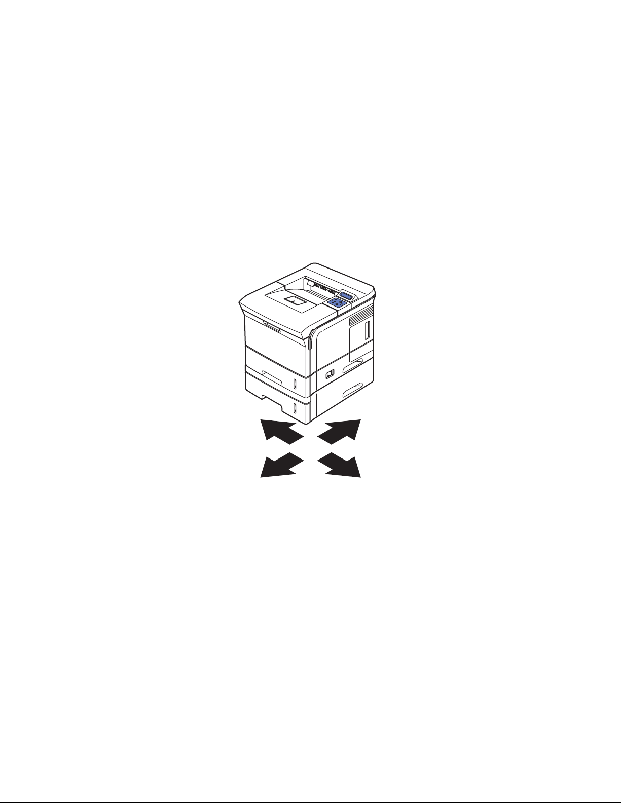
Repairs and Adjustments
Overview
This section contains the removal and replacement procedures for selected parts of the printer
according to the Service Parts List. Not all Replacement Procedures are included in this
Service Manual. In most cases, to reinstall a part, simply reverse the Removal Procedure
shown. In some instances, the Replacement Procedure is included, because it may contain
special steps. For specific assemblies and parts, see Parts List on page 5-1.
Standard Orientation of the Printer
When needed, the orientation of the printer is called out in the procedure for locating printer parts. Refer
to the printer orientation graphic for locating the right, left, front and back sides of the printer.
FRONT
REARLEFT
RIGHT
s3500-056
Phaser® 3500 Laser Printer Service Manual
4-2
Page 47

Repairs and Adjustments
General Notes on Disassembly
Preparation
Before you begin any Removal and Replacement Procedure:
1. Switch OFF the printer power and disconnect the power cord from the wall outlet.
2. Remove the Print Cartridge and protect it from exposure to light by covering it with a light
proof bag or by placing it in a light-tight container.
3. Disconnect all computer interface cables from the printer.
4. Wear an electrostatic discharge wrist strap to help prevent damage to the sensitive
electronics of the printer circuit boards.
5. Remove the Fuser Assembly or wait at least 5 minutes after you have switched OFF
printer power for the Fuser to cool before you work on or around the Fuser.
6. Tray 2 can interfere with the removal of many printer parts. Remove Tray 2 before further
disassembly.
Wherever this video icon appears throughout the manual, detailed
instructions for that procedure are available with videos on the
Phaser 3500 Product Training CD-ROM.
Note: Part names that appear in the disassembly procedures may not exactly match the names
that appear in the Parts List. For example, a part called the Registration Transport Assembly
may appear on the Parts List as Assembly, Transport Regi.
Caution: Many parts are secured by plastic tabs. DO NOT over flex or force these parts. Do
not over torque the screws threaded into plastic parts.
Always use the correct type and size screw. Using the wrong screw can damage tapped holes.
Do not use excessive force to either remove or install either a screw or a printer part.
A spring hook is required for removal and replacement of the various springs in the printer.
Springs can be damaged using pliers or other tools for this task.
Warning: Unplug the AC power cord from the wall outlet before removing any printer part.
Notations in the Disassembly Text
■ The notation “(item X)” points to a numbered callout in the illustration corresponding to the
disassembly procedure being performed.
■ The notation “PLX.X.X” indicates that this component is listed in the Parts List.
■ Bold arrows in an illustration show direction of movement when removing or
replacing a component.
Phaser® 3500 Laser Printer Service Manual
4-3
Page 48

Repairs and Adjustments
Covers
Right Cover
1. Disconnect the power cord.
2. Remove the Duplex Unit.
3. Remove the 2 rear screws securing the Right Cover to the rear of the
printer.
Note: In the next step, ensure the power switch is in the OFF position in order to free the
Right Cover.
4. Slide the Right Cover towards the rear of the printer to release the 3 tabs, and remove it
from the printer.
Phaser® 3500 Laser Printer Service Manual
4-4
Cover Right
s3500-068
Page 49

Repairs and Adjustments
Left Cover
1. Disconnect the power cord.
2. Remove the Duplex Unit.
3. Open the Rear Cover for access to the rear top screw.
4. Remove 2 screws, from the rear of the printer, securing the Left Cover.
5. Close the Rear Cover.
6. Slide the left cover towards the rear of the printer to release the 3 tabs securing it to the
printer.
Cover-Left
Phaser® 3500 Laser Printer Service Manual
4-5
s3500-080
Page 50
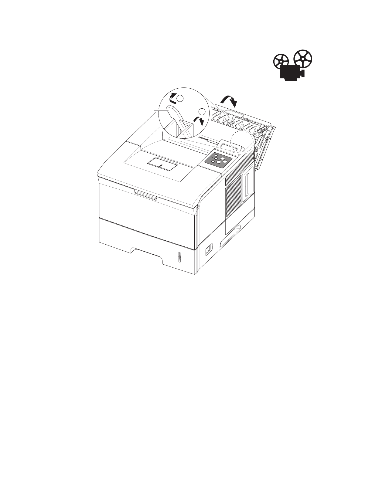
Rear Cover
1. Open the Rear Cover.
2. Release the Restraining Strap (tie stopper).
1
Repairs and Adjustments
Tie Stopper
2
s3500-081
Phaser® 3500 Laser Printer Service Manual
4-6
Page 51

Repairs and Adjustments
3. To release the 2 posts securing the Rear Cover; Lift up on the left (printer left) hinge pin,
then slide the Rear Cover to the left to free the right hinge pin and remove the Rear Cover
from the printer.
Rear Cover
1
2
s3500-082
Phaser® 3500 Laser Printer Service Manual
4-7
Page 52
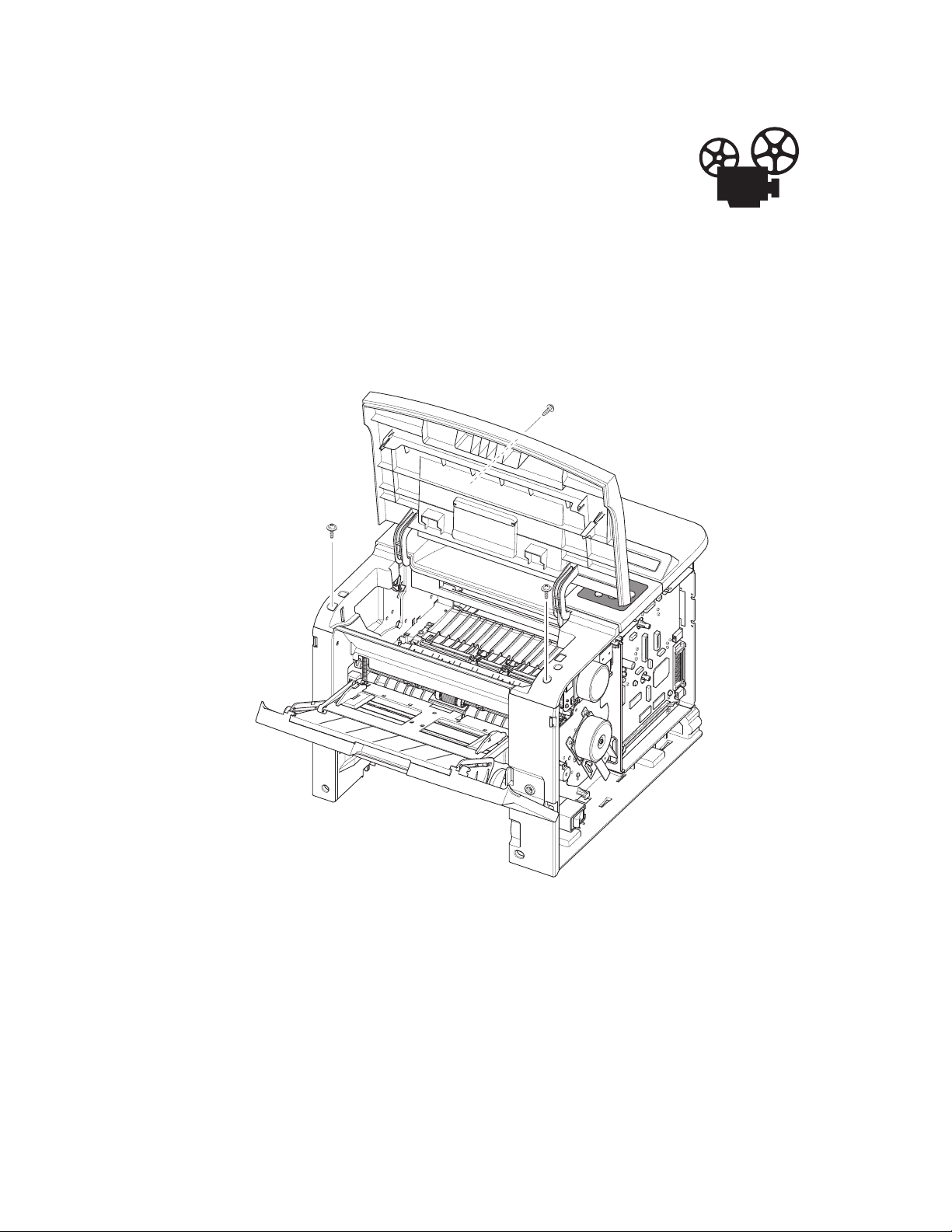
Repairs and Adjustments
Top Cover
1. Remove the Print Cartridge and protect it from light exposure.
2. Remove:
■ Covers on page 4-4
■ Left Cover on page 4-5
Note: Open the Rear and Top Covers for access.
3. Remove the 2 screws located on the front of the Top Cover.
4. On the rear, left side of the printer, remove 1 screw securing the Top Cover.
Phaser® 3500 Laser Printer Service Manual
4-8
s3500-083
Page 53

Repairs and Adjustments
5. Release 3 tabs, one on the left, one on the right, and one on the rear of the Top Cover.
s3500-085
6. Disconnect the Control Panel wiring harnesses from the Main Board, note the connector
location and routing for reassembly.
Phaser® 3500 Laser Printer Service Manual
4-9
Page 54

Repairs and Adjustments
Control Panel and LCD Display
1. Remove:
■ Top Cover on page 4-8
2. Remove the 6 screws securing the LCD and control panel and remove from the top cover.
■ 2 screws to the LCD Board.
■ 4 screws on the key panel board.
Note: DO NOT remove the 3 screws securing the plastic portion of the LCD display.
LCD Panel
Key Panel
s3500-086
Phaser® 3500 Laser Printer Service Manual
4-10
Page 55

Repairs and Adjustments
Open Cover
1. Remove:
■ Covers on page 4-4
■ Left Cover on page 4-5
■ Top Cover on page 4-8
2. Remove the 2 screws and stoppers from the Open Cover.
3. Remove the Open Cover from the Top Cover by flexing the 2 tabs as shown below.
Open Cover
Stopper
s3500-087
s3500-088
Phaser® 3500 Laser Printer Service Manual
4-11
Page 56

Repairs and Adjustments
Tray 1 (MPT) Assembly
1. Open Tray 1.
2. Unhook the 2 springs connecting the Knock-up Plate to the Pick-Up
Rack.
Note: DO NOT unhook the springs from the Pick-Up Rack.
s3500-058
Note: In the next step, if you exert too much pressure you can break the tracks.
Phaser® 3500 Laser Printer Service Manual
4-12
Page 57

Repairs and Adjustments
3. Flex the left and right side tracks to disengage the Knock-Up Plate from the Tray 1
Assembly.
Caution: Tray 1 and the Knock-Up Plate contain unsecured plastic parts that fall off and
are easy to lose.
Tray Link
s3500-059
4. Slide Tray 1 to the right side of the printer to release the 4 pivot points securing the Tray,
then remove the Tray 1 Assembly from the printer.
Phaser® 3500 Laser Printer Service Manual
4-13
Page 58

Repairs and Adjustments
Tray 1 Knock-Up Plate
1. Follow all the steps for removing the Tray 1 (MPT) Assembly on page 4-12.
2. Rotate the tray links down slightly until they come free from the printer.
Note: The tray links are marked “L” for the left and “R” for the right.
3. To free the Knock-Up Plate, carefully spread the slotted hinge piece to release the post,
then remove the Knock-Up Plate.
Note: Tray 1 and the Knock-up Plate contain unsecured plastic parts that fall off and are
easy to lose.
Knock Up Plate Ass'y
Phaser® 3500 Laser Printer Service Manual
Tray Link
4-14
s3500-060
Page 59

Repairs and Adjustments
Tray 1 Pick-Up Rack
1. Remove 2 screws securing the Pick-Up Rack and remove the rack.
2. Separate the clips from the Pick Roller shaft and remove the Pick-Up Rack.
Caution: Do not remove or loose the springs.
MP Pick Up Rack
s3500-118
Phaser® 3500 Laser Printer Service Manual
4-15
Page 60

Inner Cover
1. Remove:
■ Tray 1 (MPT) Assembly on page 4-12
■ Top Cover on page 4-8
2. Open or remove Tray 2 for better access.
3. Remove 2 screws securing the Inner Cover to the printer frame.
4. Remove the Inner Cover.
Repairs and Adjustments
Inner Cover
s3500-089
Phaser® 3500 Laser Printer Service Manual
4-16
Page 61

Repairs and Adjustments
Transfer Roller
Caution: Do not touch the surface of the Transfer Roller.
1. Open the Top Cover.
2. Remove the Print Cartridge and protect it from exposure to light.
3. Remove the cap from the left side of the Transfer Roller.
4. Pinch the bearing clips on both ends of the Transfer Roller.
Note: The gear on the left end of the Transfer Roller shaft is not secured in place. Hold
the gear when removing the roller to prevent it from falling into the printer.
Note: The 2 bearing clips are not interchangeable, and the levers face the rear of the
printer. The clip with the ground contact goes on the gear side of the Transfer Roller.
5. Slide the roller slightly to the right so the end of the shaft clears the lip on the printer case
and lift the Transfer Roller, together with the Bearing Clips and the Transfer Roller Gear,
out of the printer.
Holder
Transfer Roller
s3500-057
Phaser® 3500 Laser Printer Service Manual
4-17
Page 62

Retard Assembly
1. Remove:
■ Tray 1 (MPT) Assembly on page 4-12
2. Squeeze the lock as shown below and take out the retard assembly.
Retard Ass'y
Repairs and Adjustments
s3500-065
Reassembly Notes
Note: When reassembling the retard roller, insert the left end of the retard shaft through
the retard roller first.
s3500-066
Phaser® 3500 Laser Printer Service Manual
4-18
Page 63

Repairs and Adjustments
Tray 1 Separator (Holder) Pad Assembly
1. Remove:
■ Tray 1 (MPT) Assembly on page 4-12
■ Tray 1 Knock-Up Plate on page 4-14
■ Retard Assembly on page 4-18
2. Disconnect the connector from the Separator Pad Assembly.
Caution: Be careful not to break the actuator flag.
There is a spring located behind the separator pad, do not loose the spring.
3. Remove the 3 screws shown below and then remove the Separator Pad Assembly from the
printer.
s3500-062
Friction Pad
MP Actuator
Holder Pad Ass'y
Phaser® 3500 Laser Printer Service Manual
4-19
s3500-063
Page 64

Feed2 Idle Unit
1. Remove:
■ Tray 1 (MPT) Assembly on page 4-12
■ Retard Assembly on page 4-18
■ Tray 1 Separator (Holder) Pad Assembly on page 4-19
2. Remove 4 screws, 2 for each of the feed idle units.
3. Remove each idle unit.
Repairs and Adjustments
Feed2 Idle Unit
Phaser® 3500 Laser Printer Service Manual
4-20
s3500-067
Page 65

Repairs and Adjustments
Registration Assembly
1. Remove:
■ Covers on page 4-4
■ Left Cover on page 4-5
■ Top Cover on page 4-8
2. Remove the Gear Cap located on the right side of the Registration Assembly, the release is
on the front of the cap.
Gear Cap
s3500-115
Phaser® 3500 Laser Printer Service Manual
4-21
Page 66

Repairs and Adjustments
3. Remove the 4 screws securing the Registration Assembly to the printer.
4. Remove the Registration Assembly from the printer.
REGI Ass'y
s3500-114
s3500-116
Phaser® 3500 Laser Printer Service Manual
4-22
Page 67

PTL Board
1. Remove:
■ Covers on page 4-4
■ Left Cover on page 4-5
■ Top Cover on page 4-8
■ Registration Assembly on page 4-21
2. Disconnect the wiring harness.
3. Remove 1 screw and take out the PTL board.
Repairs and Adjustments
PTL Upper
Terminal
PTL PBA
Phaser® 3500 Laser Printer Service Manual
4-23
s3500-117
Page 68

Repairs and Adjustments
Main Drive Assembly and Registration (Feed) Clutch
1. Remove:
■ Covers on page 4-4
Feed Clutch
1. Loosen the grounding bracket screw attached to the plate on the Main Drive Assembly,
and rotate the grounding bracket to gain access to the e-ring.
2. Remove the e-ring securing the clutch to the feed roller shaft.
3. Disconnect the connector to the connector board, and remove the clutch from the printer.
Clutch
E-Ring
s3500-073
Phaser® 3500 Laser Printer Service Manual
4-24
Page 69

Main Drive Assembly
1. Disconnect 1 connector from the main motor assembly.
2. Remove the 6 screws securing the Main Drive to the printer.
3. Remove the Main Drive from the printer.
Repairs and Adjustments
Main Drive
Ass'y
s3500-074
Replacement Notes
Note: There are numbers for replacing each of the 6 screws in the appropriate order when
reassembling the Main Drive Assembly. There is a veristor that is secured underneath the
number 3 screw.
Phaser® 3500 Laser Printer Service Manual
4-25
Page 70

Repairs and Adjustments
Tray 1 Pick-Up Assembly and Pick Rollers
Tray 1 Pick Roller Only
Note: If you are only removing the Pick Roller, and not the shaft, it may be necessary to
rotate the shaft, release the solenoid, and then rotate the shaft gear clockwise to position
the roller properly.
Caution: Do not break the pick shaft by trying to force the pick roller off.
1. Slide the idle gears outward. Release the locking tab on the pick roll assembly and slide
the roller to the right.
1
1
Pick Roller
Idle
2
s3500-123
Phaser® 3500 Laser Printer Service Manual
4-26
Page 71

Repairs and Adjustments
Pick Roller and Shaft Removal
1. Remove:
■ Covers on page 4-4.
■ Left Cover on page 4-5.
■ Top Cover on page 4-8.
■ Tray 1 (MPT) Assembly on page 4-12.
■ Inner Cover on page 4-16.
■ Main Drive Assembly and Registration (Feed) Clutch on page 4-24.
2. On the left side of the printer, remove the locking bearing on the front of the shaft by
rotating it in the direction of the arrows shown below.
Bearing
Phaser® 3500 Laser Printer Service Manual
4-27
s3500-119
Page 72

Repairs and Adjustments
3. Remove 1 screw, on the right end of the shaft, securing the bracket, remove the bracket
with the bearing.
Bracket
Gear ass'y
Bearing
s3500-120
4. Remove the right side gear from the shaft.
5. Lift the latch on the idle cam and slide the shaft to the right, throught the cam, to free it
from the printer.
1
2
Idle-Cam
Phaser® 3500 Laser Printer Service Manual
4-28
s3500-121
Page 73

Repairs and Adjustments
Tray 2 Pick-Up Assembly and Rollers
Note: It is not necessary to remove the entire assembly in order to
remove the Pick Rollers.
1. Remove:
■ Covers on page 4-4
■ Left Cover on page 4-5
■ Top Cover on page 4-8
■ Tray 1 (MPT) Assembly on page 4-12
■ Inner Cover on page 4-16
■ Main Drive Assembly and Registration (Feed) Clutch on page 4-24
■ Tray 2 and Tray 3 (if installed)
2. Release the latch on the pick-up cam and slide off the right side of the shaft.
2
1
Gear-Pick Up Cam
Phaser® 3500 Laser Printer Service Manual
4-29
s3500-124
Page 74

Repairs and Adjustments
3. Remove the e-clip from the feed shaft.
4. Remove the locking bearing, rotating in the direction of the arrow as shown below.
Bearing
Feed2
Gear
5. Remove the gear by sliding off the shaft.
6. Turn the printer onto its left side.
7. Remove the front crossbar secured by 2 screws.
s3500-125
Bottom Cross Bar
Phaser® 3500 Laser Printer Service Manual
4-30
s3500-127
Page 75

8. Slide the actuator down and remove it from the printer.
Actuator
2
1
Repairs and Adjustments
s3500-128
9. Remove the 4 screws securing the pick assembly and manuever the pick assembly out of
the printer.
1
Pick Up Unit
3
2
Phaser® 3500 Laser Printer Service Manual
4-31
s3500-129
Page 76
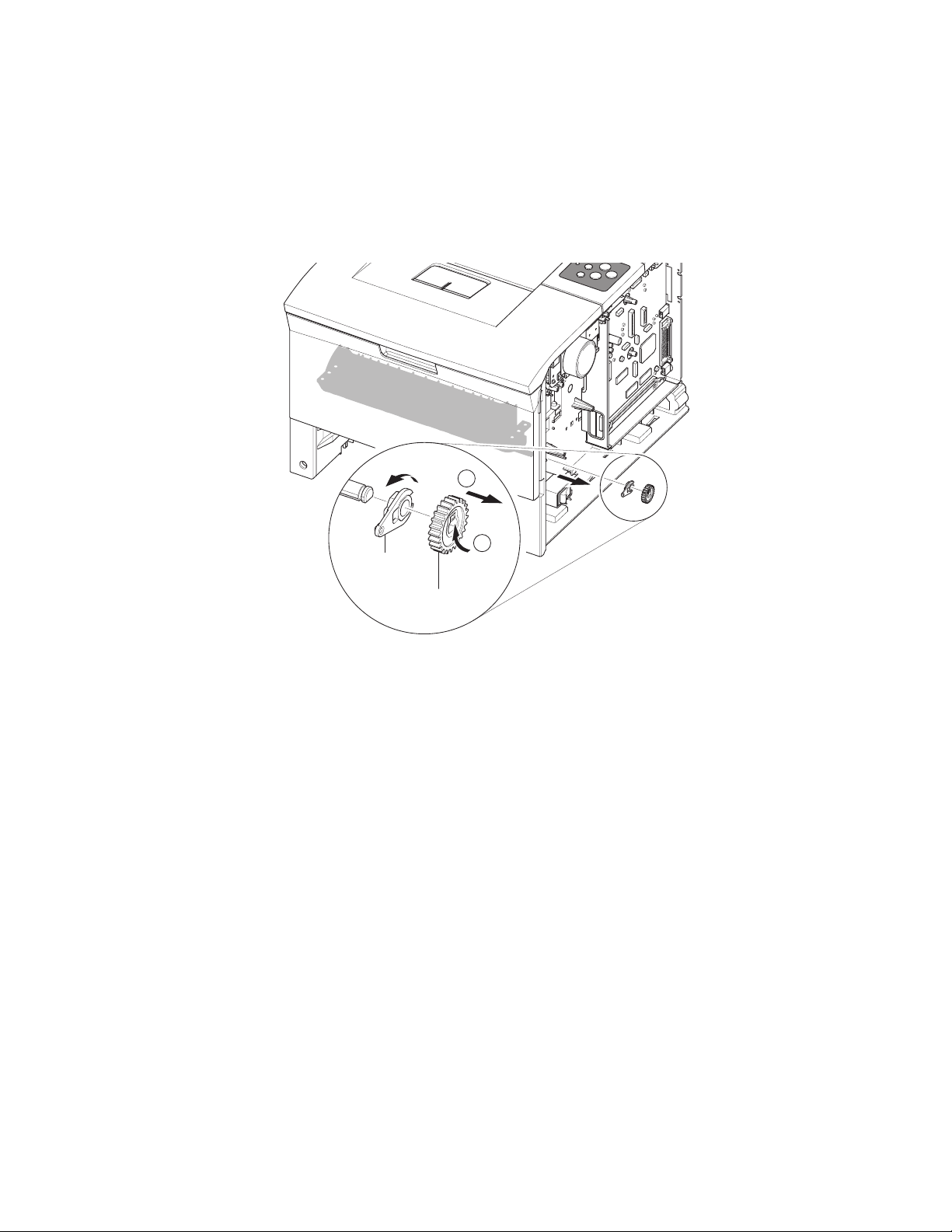
Repairs and Adjustments
Feed 2 Unit
1. Perform all steps for Tray 2 Pick-Up Assembly and Rollers on page 4-29.
2. Remove the pick up gear.
3. Remove remove the locking bearing.
4. Remove the 4 screws securing the Feed 2 Unit to the printer and remove the assembly.
2
Bearing
1
Pick Up Gear
s3500-126
Phaser® 3500 Laser Printer Service Manual
4-32
Page 77

Developer Drive Assembly
1. Remove:
■ Covers on page 4-4
2. Disconnect the connector from the developer drive assembly.
3. Remove 4 screws securing the developer drive to the printer.
Repairs and Adjustments
DEVE Drive
Ass'y
s3500-075
Replacement Notes
Note: There are numbers for replacing each of the 4 screws in the appropriate order when
reassembling the Developer Drive Assembly.
Phaser® 3500 Laser Printer Service Manual
4-33
Page 78

Connector Board
1. Remove:
■ Covers on page 4-4
2. Disconnect all connectors to the connector board.
3. Remove 1 screw securing the board to the chassis.
4. Remove the connector board.
Repairs and Adjustments
Connector
PBA
s3500-076
Phaser® 3500 Laser Printer Service Manual
4-34
Page 79

Tray 1 (MPT) Solenoid
1. Remove:
■ Covers on page 4-4
2. Disconnect the connector to the Tray 1 Solenoid.
3. Remove 1 screw securing the Tray 1 Solenoid.
Repairs and Adjustments
MP Solenoid
s3500-078
Phaser® 3500 Laser Printer Service Manual
4-35
Page 80

Main Solenoid
1. Remove:
■ Covers on page 4-4
■ Feed Clutch on page 4-24
2. Disconnect the connector to the Main Solenoid.
3. Remove 1 screw securing the Main Solenoid.
Repairs and Adjustments
Main Solenoid
s3500-079
Phaser® 3500 Laser Printer Service Manual
4-36
Page 81

Fuser Assembly
1. Remove:
■ Rear Cover on page 4-6
2. Pull the locking lever and take out the Fuser Assembly.
Repairs and Adjustments
Fuser Ass'y
Thermistor
Connector
s3500-090
Phaser® 3500 Laser Printer Service Manual
4-37
Page 82

Repairs and Adjustments
Exit Solenoid Assembly
1. Remove:
■ Covers on page 4-4
■ Left Cover on page 4-5
■ Top Cover on page 4-8
2. Disconnect the connector running to the main board.
3. Remove 3 screws securing the solenoid to the printer.
4. Remove the solenoid assembly.
Note: There is a resistor attached by the upper right hand screw. When reassembling the
printer, ensure the resistor is in place.
Exit Solenoid
Ass'y
Phaser® 3500 Laser Printer Service Manual
4-38
s3500-099
Page 83

Repairs and Adjustments
Exit and Duplex Rollers
1. Remove:
■ Covers on page 4-4
■ Left Cover on page 4-5
■ Top Cover on page 4-8
Note: When you remove the exit rollers, the rollers underneath are spring loaded and can
become lost if not careful.
2. Remove the locking bearings from both ends of the shaft.
Exit Roller
Rack-Exit Roller
Bearing
Phaser® 3500 Laser Printer Service Manual
4-39
s3500-101
Page 84

Exit Gear
1. Remove the bearing in order to remove the gear.
Bearing
2
Tray Full Actuator
1. Remove the actuator from the exit roller.
Repairs and Adjustments
1
Exit Gear
s3500-102
Actuator
s3500-100
Phaser® 3500 Laser Printer Service Manual
4-40
Page 85

Repairs and Adjustments
Duplex Roller
1. Using a small flatblade screwdriver, spread apart the bearings on both side of the duplex
roller and remove from the printer.
Duplex
Exit Roller
Holder
s3500-103
Phaser® 3500 Laser Printer Service Manual
4-41
Page 86

Repairs and Adjustments
Laser (LSU) Assembly and Lower Cover
1. Remove:
■ Covers on page 4-4
■ Left Cover on page 4-5
■ Top Cover on page 4-8
2. Remove the cover-frame exit cover.
3. Disconnect the connector from the LSU to the Main Board.
4. Remove the 3 screws securing the LSU to the chassis.
5. Remove the LSU from the printer.
Note: The screws are numbered and need to be replaced and tightened in the correct order.
LSU
s3500-106
Phaser® 3500 Laser Printer Service Manual
4-42
Page 87

LSU Lower Cover
1. Remove 1 screw securing the fan duct.
2. Remove the fan and duct to access the screw in the next step.
3. Remove 3 screws securing the LSU Cover and remove the cover.
4. Disconnect all the connectors running to the LSU Cover.
Repairs and Adjustments
LSU Lower
Cover
Phaser® 3500 Laser Printer Service Manual
4-43
s3500-113
Page 88

Left Side Cooling Supply Fan and Duct
1. Remove:
■ Covers on page 4-4
■ Left Cover on page 4-5
■ Top Cover on page 4-8
■ Laser (LSU) Assembly and Lower Cover on page 4-42
2. Disconnect the connector to the Toner Sensor Board.
3. Remove 1 screw to remove the fan from the printer.
DC Fan
Stopper
Repairs and Adjustments
Phaser® 3500 Laser Printer Service Manual
4-44
s3500-108
Page 89

Repairs and Adjustments
Toner Sensor Board and CRUM
1. Remove:
■ Covers on page 4-4
■ Left Cover on page 4-5
■ Top Cover on page 4-8
■ Laser (LSU) Assembly and Lower Cover on page 4-42
2. Disconnect all connectors running to the toner sensor board.
3. Remove 2 screws securing the toner sensor board to the LSU cover.
4. Release the 2 locking tabs to remove the board.
Toner Sensor PBA
HV Small
Spring
Phaser® 3500 Laser Printer Service Manual
4-45
s3500-111
Page 90

Repairs and Adjustments
Cover Open Board and Harness Cover
1. Remove:
■ Covers on page 4-4
■ Left Cover on page 4-5
■ Top Cover on page 4-8
■ Laser (LSU) Assembly and Lower Cover on page 4-42
2. Remove 1 screw securing the cover open housing harness cover.
3. Release the latching tab and remove the cover open housing harness cover.
4. Disconnect the connector from the main board.
5. Using a small flatbladed screwdriver, release the 4 tabs to remove the cover open board.
Cover Open PBA
Harness Cover
Cover Open
Phaser® 3500 Laser Printer Service Manual
4-46
s3500-112
Page 91

Repairs and Adjustments
A
Main Board and Shield
Note: If the NIC Board is installed, it must be removed to access screws to the main
board.
NVRAM parameters are not transferable to the replacement board. These parameters
include serial number and copy count. Serial Number can be reinstalled via CentreWare IS
if the NIC Board is installed or via a downloadable PJL command. Observe proper ESD
procedures when removing or replacing any circuit boards in the printer.
1. Remove:
■ Covers on page 4-4
2. Disconnect all connectors from the Main Board.
3. Remove the NIC card or the dummy bracket from the main board.
4. Remove the 6 screws (4 on the Main Board and 2 to the parallel connector) securing the
Main Board to the printer, and then remove the Main Board.
5. Position the retainers on the parallel port connector straight out from the connector for
removal.
6. Move the board toward the front of the printer so the connectors clear the bracket and
remove the Main Board to the right.
7. Remove 1 screw in the center of the shield.
8. Turn the printer onto its left side and remove the rear crossbar and the right duplex guide.
9. Remove the right rear corner screw from the power supply shield to remove.
Phaser® 3500 Laser Printer Service Manual
4-47
Main PB
s3500-071
Page 92

Power Supply and Shield
1. Remove:
■ Print Cartridge
■ Tray 2 and Tray 3 (if installed)
■ Covers on page 4-4
■ Rear Cover on page 4-6
■ Fuser Assembly on page 4-37
2. Turn the printer onto it’s left side.
3. Remove the rear crossbar secured by 2 screws.
4. Remove the Tray 2 no paper actuator for better access.
5. Remove the left and right duplex unit guides.
Repairs and Adjustments
Guide-Duplex L
Guide-Duplex R
Phaser® 3500 Laser Printer Service Manual
4-48
s3500-136
Page 93

Repairs and Adjustments
6. Remove 5 screws from the power supply shield.
7. Remove 1 grounding screw from the rear of the power supply shield.
Engine Shield
Ass'y
s3500-135
8. Pull out the shield slightly and disconnect all connectors to the power supply board.
9. Remove the power supply from the printer.
Engine Shield Ass'y
Phaser® 3500 Laser Printer Service Manual
4-49
s3500-137
Page 94

Repairs and Adjustments
Fuser Gear Assembly
1. Remove:
■ Print Cartridge
■ Tray 2 and Tray 3 (if installed)
■ Covers on page 4-4
■ Rear Cover on page 4-6.
■ Fuser Assembly on page 4-37
■ Exit Solenoid Assembly on page 4-38
■ Main Board and Shield on page 4-47
2. Remove the 3 screws securing the fuser gear train and remove it from the printer.
Phaser® 3500 Laser Printer Service Manual
4-50
Page 95

Repairs and Adjustments
Paper Size Sensor
Note: If the optional Tray 3 Feeder is installed, it must be removed before perfoming this
procedure.
1. Remove:
■ Print Cartridge
■ Tray 2 and Tray 3 (if installed)
■ Left Cover on page 4-5
2. Disconnect CN 1 from the Paper Size Sensor.
3. Gently turn the printer upside down.
Note: The Paper Size Sensor can be removed and replaced without removing the rear
crossbar. However, to provide improved access, remove the crossbar screw above the
Paper Size Sensor and loosen the screw on the other side so you can swing the crossbar out
of the way.
4. On the left side of the printer, remove 2 screws, one on either side of the rear crossbar, that
secure the Paper Size Sensor to the printer chassis.
5. Pull up on the sensor assembly until it is clear of the mounting pins and then remove it
from the printer.
Phaser® 3500 Laser Printer Service Manual
4-51
Page 96

Parts List
This section covers the following:
■ Using the Parts List on page 5-2
■ PL 8.1 Main Assembly on page 5-3
■ PL 8.2 Cover Assembly on page 5-7
■ PL 8.3 Frame Assembly on page 5-9
■ PL 8.4 Fuser Assembly on page 5-17
■ PL 8.9 Tray 2 Cassette on page 5-20
■ PL 8.10 Tray 3 Cassette on page 5-22
■ PL 8.11 Duplex Assembly on page 5-25
Phaser® 3500 Laser Printer Service Manual
5-1
Page 97

Parts List
Using the Parts List
1. No.: The callout number from the exploded part diagram.
2. Part Number: The material part number used to order specific parts.
3. Qty: This number represents the parts per printer, not the number of parts supplied in the
actual part order.
4. Name/Description: Details the name of the part to be ordered and the number of parts
supplied per order.
5. Parts identified throughout this manual are referenced PL #.#.#; For example, PL 3.1.10
means the part is item 10 of Parts List 3.1.
6. A black triangle preceding a number followed by a parenthetical statement in an illustrated
parts list means the item is a parent assembly, made up of the individual parts called out in
parentheses.
7. The notation “with X~Y” following a part name indicates an assembly that is made up of
components X through Y. For example, “1 (with 2~4)” means part 1 consists of part 2, part
3, and part 4.
8. An asterisk (*) following a part name indicates the page contains a note about this part.
9. The notation (NS) next to a part indicates that pariticular part is not spared, but contained
in a kit or major assembly.
10. The notation “J1<>J2 and P2” is attached to a wire harness. It indicates that connector
Jack 1 is attached to one end of the wire harness and connector J2 is attached to the other
end that is plugged into P2.
Only parts showing part numbers are available for support. Parts not showing part
numbers are available on the parent assembly.
Legend:
Identifier Meaning
CC-ring
EE-ring
KL K-clip
SScrew
Phaser® 3500 Laser Printer Service Manual
5-2
Page 98

PL 8.1 Main Assembly
10
8
8-1
8-2
8-3
8-4
7
15
34
32
12
31
14
11
13
Parts List
0
2
37
3
9-1
9-2
9-3
9
38
16
3-4
3-3
3-6
3-5
3-2
3-1
39(Network only)
39-2
35
19
17
1
24
18
20-1
20-3
20-2
22
20
4
23
30
29
30
28
36
25
26
21
27
21-2
21-3
21-1
5
4-1
39-1
40
6
4-2
Phaser® 3500 Laser Printer Service Manual
5-3
Page 99

PL 8.1 Parts List Table
Main Assembly
Item No. Description Qty Part Number
1 ELA UNIT FRAME BASE
2 ELA HOU BASE HOUSING
3 MEA UNIT KNOCK UP MP 050N00475
3.1 PLATE M KNOCK UP MP
3.2 MPR PAD KNOCK UP MP
3.3 PMO SIDE GUIDE MP R
3.4 PMO SIDE GUIDE MP L
3.5 GEAR PINION
3.6 SHAFT REINFORCEMENT
4 MEA UNIT COVER MP XRX 002N02410
Parts List
4.1 COVER M MP XRX
4.2 TRAY M EXTND MP
5 TRAY M LINK MP L 012N00521
6 TRAY M LINK MP R 012N00522
7 ROLLER TRANSFER 022E29520
8 ELA UNIT HOLDER TR R 019E63470
8.1 PMO BUSHING TR
8.2 SPRING ETC TR R HAWK
8.3 PMO TRANSFER HOLDER
8.4 IPR PLATE TR
9 ELA UNIT HOLDER TR L 019E63480
9.1 PMO BUSHING TR
9.2 SPRING ETC TR R HAWK
9.3 PMO TRANSFER HOLDER
10 PMO CAP TR 021N02248
11 GEAR TR29 (Transfer) 007N01013
12 ELA UNIT REGI (Registration Assembly) 022N02171
13 GEAR REGI Z25 007N01360
14 CAP M GEAR 807E06450
15 UNIT LSU (Laser Unit) 122N00242
Phaser® 3500 Laser Printer Service Manual
5-4
Page 100

Main Assembly (Continued)
Item No. Description Qty Part Number
16 ELA UNIT EXIT SOLENOID 121N01100
17 ELA UNIT DEVE MOTOR 127N07389
18 ELA UNIT MAIN MOTOR 127N07390
19 PBA MAIN (Main Board) 140N63016
20 MEA UNIT GEAR PICK UP 007N01361
20.1 GEAR M PICK UP CAM
20.2 GEAR M PICK UP
20.3 SPRINT ETC CAM MP
21 MEA UNIT GEAR P/UP MP CARDINAL 007K13470
21.1 GEAR MP HOLDER CAM
21.2 GEAR MP PICK UP
21.3 SPRING ETC CAM MP
Parts List
22 BEARING PICK UP
23 BRACKET P SHAFT MP
24 MEP CLUTCH FEED 121N01101
25 SOLENOID MAIN 121E19250
26 SOLENOID MP 121N01102
27 RING E
28 SHIELD P SMPS
29 SMPS V1 HVPS - 110V
SMPS V2 HVPS - 220V
30 BAR P CROSS BOTTOM
31 FAN DC 127E14630
32 STOPPER M FAN80
34 ELA UNIT DEVE (Print Cartridge)
6K Toner Cartridge
12K Toner Cartridge
35 ELA UNIT CASSETTE (Tray 2) 109R00756
36 ELA UNIT SCF (Optional Tray 3) 050N00476
105N02059
105N02060
106R01148
106R01149
37 ELA UNIT DUPLEX 084N00718
38 BRACKET P DUMMY CTRL 015N00555
39 ELA HOU NPCE High (Network Interface Card) 140N63021
Phaser® 3500 Laser Printer Service Manual
5-5
 Loading...