

Page 1
Phaser® 3320 and WorkCentre® 3315/3325
Service Manual
Product Photo
Phaser® 3320 and
®
WorkCentre
3315/3325
Service Manual
Xerox Internal-Use Only
Page 2

Phaser 3320
WorkCentre 3315/3325
Service Manual
WARNING: The following servicing instructions are for use by qualified service
personnel only. To avoid personal injury, do not perform any servicing other than
that contained in the operating instructions, unless you are qualified to do so.
First Printing: June 2012 Xerox Internal Use Only
Page 3

Prepared By:
Xerox Corporation
Content Development and Language Services
26600 SW Parkway
Wilsonville, OR 97070
© 2012 by Xerox Corporation. All rights reserved. XEROX® and XEROX and Design®, Phaser®, CentreWare®, PrintingScout®, Walk-Up®,
WorkCentre®, FreeFlow®, SMARTsend®, Scan to PC Desktop®, ColorQube, Global Print Driver®, and Mobile Express Driver are trademarks of
Xerox Corporation in the United States and/or other countries
Unpublished rights reserved under the copyright laws of the United States. Contents of this publication may not be reproduced in any form
without permission of Xerox Corporation.
Copyright protection claimed includes all forms and matters of copyrightable materials and information now allowed by statutory or judicial
law or hereinafter granted, including without limitation, material generated from the software programs which are displayed on the screen
such as styles, templates, icons, screen displays, looks, etc.
Xerox technical training materials and service manuals are intended for use by authorized Xerox service technicians and service partners only
and are not for resale. These materials may not be distributed, copied, or otherwise reproduced without prior written consent from Xerox
Corporation.
Adobe Reader®, Adobe Type Manager®, ATM™, and PostScript® are trademarks of Adobe Systems Incorporated in the United States and/or
other countries.
Apple®, AppleTalk®, Bonjour®, EtherTalk®, LaserWriter®, LocalTalk®, Macintosh®, Mac OS®, and TrueType® are trademarks of Apple
Computer, Inc. in the United States and/or other countries.
HP-GL®, HP-UX®, and PCL® are trademarks of Hewlett-Packard Corporation in the United States and/or other countries.
Windows®, Vista™, and Windows Server™ are trademarks of Microsoft Corporation in the United States and/or other countries.
Novell®, NetWare®, NDPS®, NDS®, Novell Directory Services®, IPX™, and Novell Distributed Print Services™ are trademarks of Novell,
Incorporated in the United States and/or other countries.
SM
Sun
, Sun Microsystems™, and Solaris™ are trademarks of Sun Microsystems, Incorporated in the United States and/or other countries.
SWOP® is a trademark of SWOP, Inc.
UNIX® is a registered trademark in the US and other countries, licensed exclusively through X/Open Company Limited.
As an ENERGY STAR® partner, Xerox Corporation has determined that this product meets the ENERGY STAR guidelines for energy efficiency.
The ENERGY STAR name and logo are registered U.S. marks.
PANTONE® Colors generated may not match PANTONE-identified standards. Consult current PANTONE Publications for accurate color.
PANTONE® and other Pantone, Inc. trademarks are the property of Pantone, Inc. © Pantone, Inc., 2000.
Page 4

Contents
1 General Information
About this Service Manual . . . . . . . . . . . . . . . . . . . . . . . . . . . . . . . . . . . . . . . . . . . . . . . . . . . . . . . . . . . . . . . 1-2
Manual Terms. . . . . . . . . . . . . . . . . . . . . . . . . . . . . . . . . . . . . . . . . . . . . . . . . . . . . . . . . . . . . . . . . . . . . . . 1-2
Manual Organization . . . . . . . . . . . . . . . . . . . . . . . . . . . . . . . . . . . . . . . . . . . . . . . . . . . . . . . . . . . . . . . . . . . . 1-3
Safety . . . . . . . . . . . . . . . . . . . . . . . . . . . . . . . . . . . . . . . . . . . . . . . . . . . . . . . . . . . . . . . . . . . . . . . . . . . . . . . . . . 1-4
Power Safety Precautions . . . . . . . . . . . . . . . . . . . . . . . . . . . . . . . . . . . . . . . . . . . . . . . . . . . . . . . . . . . .1-4
Electrostatic Discharge (ESD) Precautions . . . . . . . . . . . . . . . . . . . . . . . . . . . . . . . . . . . . . . . . . . . . .1-4
Service Safety Summary . . . . . . . . . . . . . . . . . . . . . . . . . . . . . . . . . . . . . . . . . . . . . . . . . . . . . . . . . . . . .1-5
Health and Safety Incident Reporting . . . . . . . . . . . . . . . . . . . . . . . . . . . . . . . . . . . . . . . . . . . . . . . .1-7
Printer Symbols. . . . . . . . . . . . . . . . . . . . . . . . . . . . . . . . . . . . . . . . . . . . . . . . . . . . . . . . . . . . . . . . . . . . . . 1-9
Regulatory . . . . . . . . . . . . . . . . . . . . . . . . . . . . . . . . . . . . . . . . . . . . . . . . . . . . . . . . . . . . . . . . . . . . . . . . .1-10
Introduction and Overview. . . . . . . . . . . . . . . . . . . . . . . . . . . . . . . . . . . . . . . . . . . . . . . . . . . . . . . . . . . . . .1-11
Technical Support Information . . . . . . . . . . . . . . . . . . . . . . . . . . . . . . . . . . . . . . . . . . . . . . . . . . . . . .1-11
Parts of the Printer . . . . . . . . . . . . . . . . . . . . . . . . . . . . . . . . . . . . . . . . . . . . . . . . . . . . . . . . . . . . . . . . . . . . .1-12
Phaser 3320 Front View. . . . . . . . . . . . . . . . . . . . . . . . . . . . . . . . . . . . . . . . . . . . . . . . . . . . . . . . . . . . .1-12
Phaser 3320 Rear and Side Views. . . . . . . . . . . . . . . . . . . . . . . . . . . . . . . . . . . . . . . . . . . . . . . . . . . .1-13
WorkCentre 3315/3320 Front Views . . . . . . . . . . . . . . . . . . . . . . . . . . . . . . . . . . . . . . . . . . . . . . . . .1-14
WorkCentre 3315/3320 Rear View. . . . . . . . . . . . . . . . . . . . . . . . . . . . . . . . . . . . . . . . . . . . . . . . . . .1-15
Control Panel . . . . . . . . . . . . . . . . . . . . . . . . . . . . . . . . . . . . . . . . . . . . . . . . . . . . . . . . . . . . . . . . . . . . . . . . . .1-16
Phaser 3320DN/I Control Panel Button Descriptions . . . . . . . . . . . . . . . . . . . . . . . . . . . . . . . . . .1-16
WorkCentre 3315DN Control Panel Button Descriptions. . . . . . . . . . . . . . . . . . . . . . . . . . . . . . .1-17
WorkCentre 3325DN/DNI Control Panel Button Descriptions . . . . . . . . . . . . . . . . . . . . . . . . . .1-18
Understanding the Status LED . . . . . . . . . . . . . . . . . . . . . . . . . . . . . . . . . . . . . . . . . . . . . . . . . . . . . .1-19
Media Path . . . . . . . . . . . . . . . . . . . . . . . . . . . . . . . . . . . . . . . . . . . . . . . . . . . . . . . . . . . . . . . . . . . . . . . . . . . .1-20
Feeder. . . . . . . . . . . . . . . . . . . . . . . . . . . . . . . . . . . . . . . . . . . . . . . . . . . . . . . . . . . . . . . . . . . . . . . . . . . . . . . . .1-21
Tray 1 . . . . . . . . . . . . . . . . . . . . . . . . . . . . . . . . . . . . . . . . . . . . . . . . . . . . . . . . . . . . . . . . . . . . . . . . . . . . .1-21
Pick Up / Retard Roller . . . . . . . . . . . . . . . . . . . . . . . . . . . . . . . . . . . . . . . . . . . . . . . . . . . . . . . . . . . . . .1-21
Registration Roller . . . . . . . . . . . . . . . . . . . . . . . . . . . . . . . . . . . . . . . . . . . . . . . . . . . . . . . . . . . . . . . . . .1-21
Bypass Tray . . . . . . . . . . . . . . . . . . . . . . . . . . . . . . . . . . . . . . . . . . . . . . . . . . . . . . . . . . . . . . . . . . . . . . . .1-22
Tray 2 . . . . . . . . . . . . . . . . . . . . . . . . . . . . . . . . . . . . . . . . . . . . . . . . . . . . . . . . . . . . . . . . . . . . . . . . . . . . .1-22
ADF . . . . . . . . . . . . . . . . . . . . . . . . . . . . . . . . . . . . . . . . . . . . . . . . . . . . . . . . . . . . . . . . . . . . . . . . . . . . . . .1-22
Duplex Unit . . . . . . . . . . . . . . . . . . . . . . . . . . . . . . . . . . . . . . . . . . . . . . . . . . . . . . . . . . . . . . . . . . . . . . . .1-23
Print Process . . . . . . . . . . . . . . . . . . . . . . . . . . . . . . . . . . . . . . . . . . . . . . . . . . . . . . . . . . . . . . . . . . . . . . . . . . .1-24
Print Cartridge . . . . . . . . . . . . . . . . . . . . . . . . . . . . . . . . . . . . . . . . . . . . . . . . . . . . . . . . . . . . . . . . . . . . .1-24
Fuser . . . . . . . . . . . . . . . . . . . . . . . . . . . . . . . . . . . . . . . . . . . . . . . . . . . . . . . . . . . . . . . . . . . . . . . . . . . . . .1-25
Laser Scanning Unit (LSU). . . . . . . . . . . . . . . . . . . . . . . . . . . . . . . . . . . . . . . . . . . . . . . . . . . . . . . . . . .1-26
Drive . . . . . . . . . . . . . . . . . . . . . . . . . . . . . . . . . . . . . . . . . . . . . . . . . . . . . . . . . . . . . . . . . . . . . . . . . . . . . . . . . .1-27
Electrical. . . . . . . . . . . . . . . . . . . . . . . . . . . . . . . . . . . . . . . . . . . . . . . . . . . . . . . . . . . . . . . . . . . . . . . . . . . . . . .1-28
Sensors . . . . . . . . . . . . . . . . . . . . . . . . . . . . . . . . . . . . . . . . . . . . . . . . . . . . . . . . . . . . . . . . . . . . . . . . . . . .1-29
Maintenance Items . . . . . . . . . . . . . . . . . . . . . . . . . . . . . . . . . . . . . . . . . . . . . . . . . . . . . . . . . . . . . . . . . . . .1-31
Consumables . . . . . . . . . . . . . . . . . . . . . . . . . . . . . . . . . . . . . . . . . . . . . . . . . . . . . . . . . . . . . . . . . . . . . . . . . .1-31
Xerox Internal Use Only Phaser 3320 and WorkCentre 3315/3325
Service Manual
iii
Page 5

Contents
Specifications . . . . . . . . . . . . . . . . . . . . . . . . . . . . . . . . . . . . . . . . . . . . . . . . . . . . . . . . . . . . . . . . . . . . . . . . . .1-32
Configurations . . . . . . . . . . . . . . . . . . . . . . . . . . . . . . . . . . . . . . . . . . . . . . . . . . . . . . . . . . . . . . . . . . . . .1-32
Paper Handling. . . . . . . . . . . . . . . . . . . . . . . . . . . . . . . . . . . . . . . . . . . . . . . . . . . . . . . . . . . . . . . . . . . . .1-34
Printing Specifications . . . . . . . . . . . . . . . . . . . . . . . . . . . . . . . . . . . . . . . . . . . . . . . . . . . . . . . . . . . . . .1-35
Scanning Specifications. . . . . . . . . . . . . . . . . . . . . . . . . . . . . . . . . . . . . . . . . . . . . . . . . . . . . . . . . . . . .1-36
Copy Specifications. . . . . . . . . . . . . . . . . . . . . . . . . . . . . . . . . . . . . . . . . . . . . . . . . . . . . . . . . . . . . . . . .1-37
Fax Specifications . . . . . . . . . . . . . . . . . . . . . . . . . . . . . . . . . . . . . . . . . . . . . . . . . . . . . . . . . . . . . . . . . .1-38
Electrical Specifications . . . . . . . . . . . . . . . . . . . . . . . . . . . . . . . . . . . . . . . . . . . . . . . . . . . . . . . . . . . . .1-39
Environmental Specifications. . . . . . . . . . . . . . . . . . . . . . . . . . . . . . . . . . . . . . . . . . . . . . . . . . . . . . . .1-40
Physical Dimensions and Clearances. . . . . . . . . . . . . . . . . . . . . . . . . . . . . . . . . . . . . . . . . . . . . . . . .1-41
Mounting Surface Specifications . . . . . . . . . . . . . . . . . . . . . . . . . . . . . . . . . . . . . . . . . . . . . . . . . . . .1-43
2 Error Troubleshooting
Introduction . . . . . . . . . . . . . . . . . . . . . . . . . . . . . . . . . . . . . . . . . . . . . . . . . . . . . . . . . . . . . . . . . . . . . . . . . . . .2-2
Monitoring Supplies Life . . . . . . . . . . . . . . . . . . . . . . . . . . . . . . . . . . . . . . . . . . . . . . . . . . . . . . . . . . . . . 2-2
Initial Actions . . . . . . . . . . . . . . . . . . . . . . . . . . . . . . . . . . . . . . . . . . . . . . . . . . . . . . . . . . . . . . . . . . . . . . .2-3
Display Problems . . . . . . . . . . . . . . . . . . . . . . . . . . . . . . . . . . . . . . . . . . . . . . . . . . . . . . . . . . . . . . . . . . . . 2-3
Printing Problems. . . . . . . . . . . . . . . . . . . . . . . . . . . . . . . . . . . . . . . . . . . . . . . . . . . . . . . . . . . . . . . . . . . .2-3
Copy/Scan Problems. . . . . . . . . . . . . . . . . . . . . . . . . . . . . . . . . . . . . . . . . . . . . . . . . . . . . . . . . . . . . . . . .2-4
ADF Problems . . . . . . . . . . . . . . . . . . . . . . . . . . . . . . . . . . . . . . . . . . . . . . . . . . . . . . . . . . . . . . . . . . . . . . . 2-4
Fax Problems. . . . . . . . . . . . . . . . . . . . . . . . . . . . . . . . . . . . . . . . . . . . . . . . . . . . . . . . . . . . . . . . . . . . . . . . 2-4
Media-Based Problems. . . . . . . . . . . . . . . . . . . . . . . . . . . . . . . . . . . . . . . . . . . . . . . . . . . . . . . . . . . . . . .2-5
Servicing Instructions. . . . . . . . . . . . . . . . . . . . . . . . . . . . . . . . . . . . . . . . . . . . . . . . . . . . . . . . . . . . . . . . . . . .2-7
Service Mode . . . . . . . . . . . . . . . . . . . . . . . . . . . . . . . . . . . . . . . . . . . . . . . . . . . . . . . . . . . . . . . . . . . . . . . . . . . 2-8
Phaser 3320 Service Mode . . . . . . . . . . . . . . . . . . . . . . . . . . . . . . . . . . . . . . . . . . . . . . . . . . . . . . . . . . . . . . . 2-9
Entering Service Mode . . . . . . . . . . . . . . . . . . . . . . . . . . . . . . . . . . . . . . . . . . . . . . . . . . . . . . . . . . . . . . . 2-9
Phaser 3320 Service Mode Menu Map . . . . . . . . . . . . . . . . . . . . . . . . . . . . . . . . . . . . . . . . . . . . . . .2-10
Service Mode Menu. . . . . . . . . . . . . . . . . . . . . . . . . . . . . . . . . . . . . . . . . . . . . . . . . . . . . . . . . . . . . . . . .2-11
WorkCentre 3315/3325 Service Mode . . . . . . . . . . . . . . . . . . . . . . . . . . . . . . . . . . . . . . . . . . . . . . . . . . .2-14
Entering Service Mode . . . . . . . . . . . . . . . . . . . . . . . . . . . . . . . . . . . . . . . . . . . . . . . . . . . . . . . . . . . . . .2-14
WorkCentre 3315/3325 Service Mode Menu Map . . . . . . . . . . . . . . . . . . . . . . . . . . . . . . . . . . . .2-14
Error Messages and Troubleshooting . . . . . . . . . . . . . . . . . . . . . . . . . . . . . . . . . . . . . . . . . . . . . . . . . . . .2-22
Error Messages . . . . . . . . . . . . . . . . . . . . . . . . . . . . . . . . . . . . . . . . . . . . . . . . . . . . . . . . . . . . . . . . . . . . .2-22
Troubleshooting Jams . . . . . . . . . . . . . . . . . . . . . . . . . . . . . . . . . . . . . . . . . . . . . . . . . . . . . . . . . . . . . .2-27
Tray and Media Errors . . . . . . . . . . . . . . . . . . . . . . . . . . . . . . . . . . . . . . . . . . . . . . . . . . . . . . . . . . . . . .2-36
Print Cartridge Errors. . . . . . . . . . . . . . . . . . . . . . . . . . . . . . . . . . . . . . . . . . . . . . . . . . . . . . . . . . . . . . . .2-41
Fuser Errors . . . . . . . . . . . . . . . . . . . . . . . . . . . . . . . . . . . . . . . . . . . . . . . . . . . . . . . . . . . . . . . . . . . . . . . .2-45
Motor Errors. . . . . . . . . . . . . . . . . . . . . . . . . . . . . . . . . . . . . . . . . . . . . . . . . . . . . . . . . . . . . . . . . . . . . . . .2-48
Laser Errors . . . . . . . . . . . . . . . . . . . . . . . . . . . . . . . . . . . . . . . . . . . . . . . . . . . . . . . . . . . . . . . . . . . . . . . .2-49
Fax Communication and Configuration Warnings . . . . . . . . . . . . . . . . . . . . . . . . . . . . . . . . . . . .2-50
Network Configuration Errors. . . . . . . . . . . . . . . . . . . . . . . . . . . . . . . . . . . . . . . . . . . . . . . . . . . . . . . .2-52
Scan to Email Warnings. . . . . . . . . . . . . . . . . . . . . . . . . . . . . . . . . . . . . . . . . . . . . . . . . . . . . . . . . . . . .2-55
System Errors . . . . . . . . . . . . . . . . . . . . . . . . . . . . . . . . . . . . . . . . . . . . . . . . . . . . . . . . . . . . . . . . . . . . . .2-57
Scanner Errors. . . . . . . . . . . . . . . . . . . . . . . . . . . . . . . . . . . . . . . . . . . . . . . . . . . . . . . . . . . . . . . . . . . . . .2-59
Other Errors . . . . . . . . . . . . . . . . . . . . . . . . . . . . . . . . . . . . . . . . . . . . . . . . . . . . . . . . . . . . . . . . . . . . . . . . . . . .2-60
Multi Sheet Picks . . . . . . . . . . . . . . . . . . . . . . . . . . . . . . . . . . . . . . . . . . . . . . . . . . . . . . . . . . . . . . . . . . .2-60
No Power . . . . . . . . . . . . . . . . . . . . . . . . . . . . . . . . . . . . . . . . . . . . . . . . . . . . . . . . . . . . . . . . . . . . . . . . . .2-61
iv
Phaser 3320 and WorkCentre 3315/3325 Xerox Internal Use Only
Service Manual
Page 6

3 Image Quality
Image Quality Overview . . . . . . . . . . . . . . . . . . . . . . . . . . . . . . . . . . . . . . . . . . . . . . . . . . . . . . . . . . . . . . . . . 3-2
Defects Associated with Specific Printer Components . . . . . . . . . . . . . . . . . . . . . . . . . . . . . . . . . .3-2
Print-Quality Defect Definitions . . . . . . . . . . . . . . . . . . . . . . . . . . . . . . . . . . . . . . . . . . . . . . . . . . . . . . . . . .3-4
Vertical Blank Line or Band. . . . . . . . . . . . . . . . . . . . . . . . . . . . . . . . . . . . . . . . . . . . . . . . . . . . . . . . . . .3-5
Vertical White Lines or Bands. . . . . . . . . . . . . . . . . . . . . . . . . . . . . . . . . . . . . . . . . . . . . . . . . . . . . . . . . 3-6
Horizontal Black Band . . . . . . . . . . . . . . . . . . . . . . . . . . . . . . . . . . . . . . . . . . . . . . . . . . . . . . . . . . . . . . . 3-7
Black or White Spots. . . . . . . . . . . . . . . . . . . . . . . . . . . . . . . . . . . . . . . . . . . . . . . . . . . . . . . . . . . . . . . . .3-8
Light or Undertone Print . . . . . . . . . . . . . . . . . . . . . . . . . . . . . . . . . . . . . . . . . . . . . . . . . . . . . . . . . . . .3-10
Black Print . . . . . . . . . . . . . . . . . . . . . . . . . . . . . . . . . . . . . . . . . . . . . . . . . . . . . . . . . . . . . . . . . . . . . . . . .3-11
Uneven Density . . . . . . . . . . . . . . . . . . . . . . . . . . . . . . . . . . . . . . . . . . . . . . . . . . . . . . . . . . . . . . . . . . . .3-12
Background Contamination . . . . . . . . . . . . . . . . . . . . . . . . . . . . . . . . . . . . . . . . . . . . . . . . . . . . . . . . .3-13
Ghosting or Residual Image . . . . . . . . . . . . . . . . . . . . . . . . . . . . . . . . . . . . . . . . . . . . . . . . . . . . . . . . .3-14
Stains on Printed Page . . . . . . . . . . . . . . . . . . . . . . . . . . . . . . . . . . . . . . . . . . . . . . . . . . . . . . . . . . . . . .3-15
Stains on Back of Page. . . . . . . . . . . . . . . . . . . . . . . . . . . . . . . . . . . . . . . . . . . . . . . . . . . . . . . . . . . . . .3-16
Blank Print . . . . . . . . . . . . . . . . . . . . . . . . . . . . . . . . . . . . . . . . . . . . . . . . . . . . . . . . . . . . . . . . . . . . . . . . .3-17
Toner Smears . . . . . . . . . . . . . . . . . . . . . . . . . . . . . . . . . . . . . . . . . . . . . . . . . . . . . . . . . . . . . . . . . . . . . .3-19
Unfused Image . . . . . . . . . . . . . . . . . . . . . . . . . . . . . . . . . . . . . . . . . . . . . . . . . . . . . . . . . . . . . . . . . . . .3-20
ADF/DADF Lines or Streaks. . . . . . . . . . . . . . . . . . . . . . . . . . . . . . . . . . . . . . . . . . . . . . . . . . . . . . . . . .3-21
Spots from ADF . . . . . . . . . . . . . . . . . . . . . . . . . . . . . . . . . . . . . . . . . . . . . . . . . . . . . . . . . . . . . . . . . . . .3-22
Test Prints . . . . . . . . . . . . . . . . . . . . . . . . . . . . . . . . . . . . . . . . . . . . . . . . . . . . . . . . . . . . . . . . . . . . . . . . . . . . .3-23
Printing the Test Pattern . . . . . . . . . . . . . . . . . . . . . . . . . . . . . . . . . . . . . . . . . . . . . . . . . . . . . . . . . . . .3-24
Image Specifications . . . . . . . . . . . . . . . . . . . . . . . . . . . . . . . . . . . . . . . . . . . . . . . . . . . . . . . . . . . . . . . . . . .3-25
Guaranteed Print Areas . . . . . . . . . . . . . . . . . . . . . . . . . . . . . . . . . . . . . . . . . . . . . . . . . . . . . . . . . . . . .3-26
Contents
4 Service Parts Disassembly
Overview . . . . . . . . . . . . . . . . . . . . . . . . . . . . . . . . . . . . . . . . . . . . . . . . . . . . . . . . . . . . . . . . . . . . . . . . . . . . . . . 4-2
Standard Orientation of the Printer . . . . . . . . . . . . . . . . . . . . . . . . . . . . . . . . . . . . . . . . . . . . . . . . . . .4-2
Preparation . . . . . . . . . . . . . . . . . . . . . . . . . . . . . . . . . . . . . . . . . . . . . . . . . . . . . . . . . . . . . . . . . . . . . . . . . 4-2
Notations in the Disassembly Text. . . . . . . . . . . . . . . . . . . . . . . . . . . . . . . . . . . . . . . . . . . . . . . . . . . . 4-3
Fastener Types . . . . . . . . . . . . . . . . . . . . . . . . . . . . . . . . . . . . . . . . . . . . . . . . . . . . . . . . . . . . . . . . . . . . . . 4-3
Consumables . . . . . . . . . . . . . . . . . . . . . . . . . . . . . . . . . . . . . . . . . . . . . . . . . . . . . . . . . . . . . . . . . . . . . . . . . . . 4-4
Print Cartridge . . . . . . . . . . . . . . . . . . . . . . . . . . . . . . . . . . . . . . . . . . . . . . . . . . . . . . . . . . . . . . . . . . . . . . 4-4
Tray 1 . . . . . . . . . . . . . . . . . . . . . . . . . . . . . . . . . . . . . . . . . . . . . . . . . . . . . . . . . . . . . . . . . . . . . . . . . . . . . . . . . .4-5
Duplex Assembly . . . . . . . . . . . . . . . . . . . . . . . . . . . . . . . . . . . . . . . . . . . . . . . . . . . . . . . . . . . . . . . . . . . . . . . . 4-6
Phaser 3320 Covers . . . . . . . . . . . . . . . . . . . . . . . . . . . . . . . . . . . . . . . . . . . . . . . . . . . . . . . . . . . . . . . . . . . . .4-7
Front Cover . . . . . . . . . . . . . . . . . . . . . . . . . . . . . . . . . . . . . . . . . . . . . . . . . . . . . . . . . . . . . . . . . . . . . . . . .4-7
Top Cover. . . . . . . . . . . . . . . . . . . . . . . . . . . . . . . . . . . . . . . . . . . . . . . . . . . . . . . . . . . . . . . . . . . . . . . . . . .4-8
Rear Door . . . . . . . . . . . . . . . . . . . . . . . . . . . . . . . . . . . . . . . . . . . . . . . . . . . . . . . . . . . . . . . . . . . . . . . . . .4-10
Left Cover. . . . . . . . . . . . . . . . . . . . . . . . . . . . . . . . . . . . . . . . . . . . . . . . . . . . . . . . . . . . . . . . . . . . . . . . . .4-11
Right Cover . . . . . . . . . . . . . . . . . . . . . . . . . . . . . . . . . . . . . . . . . . . . . . . . . . . . . . . . . . . . . . . . . . . . . . . .4-12
Xerox Internal Use Only Phaser 3320 and WorkCentre 3315/3325
Service Manual
v
Page 7

Contents
WorkCentre 3315/3325 Covers. . . . . . . . . . . . . . . . . . . . . . . . . . . . . . . . . . . . . . . . . . . . . . . . . . . . . . . . . .4-13
Front Cover . . . . . . . . . . . . . . . . . . . . . . . . . . . . . . . . . . . . . . . . . . . . . . . . . . . . . . . . . . . . . . . . . . . . . . . .4-13
Rear Door . . . . . . . . . . . . . . . . . . . . . . . . . . . . . . . . . . . . . . . . . . . . . . . . . . . . . . . . . . . . . . . . . . . . . . . . . .4-15
Left Cover. . . . . . . . . . . . . . . . . . . . . . . . . . . . . . . . . . . . . . . . . . . . . . . . . . . . . . . . . . . . . . . . . . . . . . . . . .4-15
Right Cover . . . . . . . . . . . . . . . . . . . . . . . . . . . . . . . . . . . . . . . . . . . . . . . . . . . . . . . . . . . . . . . . . . . . . . . .4-17
Middle Cover . . . . . . . . . . . . . . . . . . . . . . . . . . . . . . . . . . . . . . . . . . . . . . . . . . . . . . . . . . . . . . . . . . . . . . .4-19
Feeder. . . . . . . . . . . . . . . . . . . . . . . . . . . . . . . . . . . . . . . . . . . . . . . . . . . . . . . . . . . . . . . . . . . . . . . . . . . . . . . . .4-22
Base Plate Pad . . . . . . . . . . . . . . . . . . . . . . . . . . . . . . . . . . . . . . . . . . . . . . . . . . . . . . . . . . . . . . . . . . . . .4-22
Tray 1 Retard Roller. . . . . . . . . . . . . . . . . . . . . . . . . . . . . . . . . . . . . . . . . . . . . . . . . . . . . . . . . . . . . . . . .4-23
Bypass Tray . . . . . . . . . . . . . . . . . . . . . . . . . . . . . . . . . . . . . . . . . . . . . . . . . . . . . . . . . . . . . . . . . . . . . . . .4-24
Bypass Tray Retard Roller . . . . . . . . . . . . . . . . . . . . . . . . . . . . . . . . . . . . . . . . . . . . . . . . . . . . . . . . . . .4-26
Bypass Tray Pick Up Assembly. . . . . . . . . . . . . . . . . . . . . . . . . . . . . . . . . . . . . . . . . . . . . . . . . . . . . . .4-27
Feed Roller . . . . . . . . . . . . . . . . . . . . . . . . . . . . . . . . . . . . . . . . . . . . . . . . . . . . . . . . . . . . . . . . . . . . . . . . .4-29
Feed Drive Assembly. . . . . . . . . . . . . . . . . . . . . . . . . . . . . . . . . . . . . . . . . . . . . . . . . . . . . . . . . . . . . . . .4-31
Pick Up, Registration, and Bypass Tray Clutches . . . . . . . . . . . . . . . . . . . . . . . . . . . . . . . . . . . . . .4-32
20 Feed Gear. . . . . . . . . . . . . . . . . . . . . . . . . . . . . . . . . . . . . . . . . . . . . . . . . . . . . . . . . . . . . . . . . . . . . . .4-35
44-29 Feed Gear/19 Idle Gear. . . . . . . . . . . . . . . . . . . . . . . . . . . . . . . . . . . . . . . . . . . . . . . . . . . . . . .4-36
Pick Up Roller . . . . . . . . . . . . . . . . . . . . . . . . . . . . . . . . . . . . . . . . . . . . . . . . . . . . . . . . . . . . . . . . . . . . . .4-36
Xerographics. . . . . . . . . . . . . . . . . . . . . . . . . . . . . . . . . . . . . . . . . . . . . . . . . . . . . . . . . . . . . . . . . . . . . . . . . . .4-38
Transfer Roller. . . . . . . . . . . . . . . . . . . . . . . . . . . . . . . . . . . . . . . . . . . . . . . . . . . . . . . . . . . . . . . . . . . . . .4-38
Laser Unit. . . . . . . . . . . . . . . . . . . . . . . . . . . . . . . . . . . . . . . . . . . . . . . . . . . . . . . . . . . . . . . . . . . . . . . . . .4-39
Fuser . . . . . . . . . . . . . . . . . . . . . . . . . . . . . . . . . . . . . . . . . . . . . . . . . . . . . . . . . . . . . . . . . . . . . . . . . . . . . .4-39
Thermistor Assembly 43
Rear Frame . . . . . . . . . . . . . . . . . . . . . . . . . . . . . . . . . . . . . . . . . . . . . . . . . . . . . . . . . . . . . . . . . . . . . . . .4-44
Exit Roller Frame . . . . . . . . . . . . . . . . . . . . . . . . . . . . . . . . . . . . . . . . . . . . . . . . . . . . . . . . . . . . . . . . . . .4-46
Exit Rollers . . . . . . . . . . . . . . . . . . . . . . . . . . . . . . . . . . . . . . . . . . . . . . . . . . . . . . . . . . . . . . . . . . . . . . . . .4-48
Main Drive . . . . . . . . . . . . . . . . . . . . . . . . . . . . . . . . . . . . . . . . . . . . . . . . . . . . . . . . . . . . . . . . . . . . . . . . . . . . .4-49
Main Drive Assembly . . . . . . . . . . . . . . . . . . . . . . . . . . . . . . . . . . . . . . . . . . . . . . . . . . . . . . . . . . . . . . .4-49
Main Drive Motor. . . . . . . . . . . . . . . . . . . . . . . . . . . . . . . . . . . . . . . . . . . . . . . . . . . . . . . . . . . . . . . . . . .4-51
RDCN 23/23 Gear and DR 19 Swing Gear . . . . . . . . . . . . . . . . . . . . . . . . . . . . . . . . . . . . . . . . . . . .4-52
Electrical. . . . . . . . . . . . . . . . . . . . . . . . . . . . . . . . . . . . . . . . . . . . . . . . . . . . . . . . . . . . . . . . . . . . . . . . . . . . . . .4-55
Main Board . . . . . . . . . . . . . . . . . . . . . . . . . . . . . . . . . . . . . . . . . . . . . . . . . . . . . . . . . . . . . . . . . . . . . . . .4-55
Wireless Board . . . . . . . . . . . . . . . . . . . . . . . . . . . . . . . . . . . . . . . . . . . . . . . . . . . . . . . . . . . . . . . . . . . . .4-56
Control Panel Board (Phaser 3320) . . . . . . . . . . . . . . . . . . . . . . . . . . . . . . . . . . . . . . . . . . . . . . . . . .4-57
Control Panel Assembly and Board (WorkCentre 3315/3325). . . . . . . . . . . . . . . . . . . . . . . . . .4-59
LCD (WorkCentre 3325). . . . . . . . . . . . . . . . . . . . . . . . . . . . . . . . . . . . . . . . . . . . . . . . . . . . . . . . . . . . .4-61
LVPS. . . . . . . . . . . . . . . . . . . . . . . . . . . . . . . . . . . . . . . . . . . . . . . . . . . . . . . . . . . . . . . . . . . . . . . . . . . . . . .4-62
HVPS . . . . . . . . . . . . . . . . . . . . . . . . . . . . . . . . . . . . . . . . . . . . . . . . . . . . . . . . . . . . . . . . . . . . . . . . . . . . . .4-62
Fax Board . . . . . . . . . . . . . . . . . . . . . . . . . . . . . . . . . . . . . . . . . . . . . . . . . . . . . . . . . . . . . . . . . . . . . . . . . .4-63
Modem Interface Cable. . . . . . . . . . . . . . . . . . . . . . . . . . . . . . . . . . . . . . . . . . . . . . . . . . . . . . . . . . . . .4-65
DADF Board. . . . . . . . . . . . . . . . . . . . . . . . . . . . . . . . . . . . . . . . . . . . . . . . . . . . . . . . . . . . . . . . . . . . . . . .4-66
ADF Board . . . . . . . . . . . . . . . . . . . . . . . . . . . . . . . . . . . . . . . . . . . . . . . . . . . . . . . . . . . . . . . . . . . . . . . . .4-69
Upper and Lower CRUM Holders and CRUM Terminal. . . . . . . . . . . . . . . . . . . . . . . . . . . . . . . . .4-69
Middle Cover Fan. . . . . . . . . . . . . . . . . . . . . . . . . . . . . . . . . . . . . . . . . . . . . . . . . . . . . . . . . . . . . . . . . . .4-72
LVPS Fan. . . . . . . . . . . . . . . . . . . . . . . . . . . . . . . . . . . . . . . . . . . . . . . . . . . . . . . . . . . . . . . . . . . . . . . . . . .4-73
Exhaust Fan. . . . . . . . . . . . . . . . . . . . . . . . . . . . . . . . . . . . . . . . . . . . . . . . . . . . . . . . . . . . . . . . . . . . . . . .4-75
Speaker . . . . . . . . . . . . . . . . . . . . . . . . . . . . . . . . . . . . . . . . . . . . . . . . . . . . . . . . . . . . . . . . . . . . . . . . . . . .4-76
vi
Phaser 3320 and WorkCentre 3315/3325 Xerox Internal Use Only
Service Manual
Page 8

Contents
Sensors and Switches . . . . . . . . . . . . . . . . . . . . . . . . . . . . . . . . . . . . . . . . . . . . . . . . . . . . . . . . . . . . . . . . . . .4-77
Out-bin Full Sensor . . . . . . . . . . . . . . . . . . . . . . . . . . . . . . . . . . . . . . . . . . . . . . . . . . . . . . . . . . . . . . . . .4-77
Registration Sensor and Feed Sensor. . . . . . . . . . . . . . . . . . . . . . . . . . . . . . . . . . . . . . . . . . . . . . . . .4-78
Feed Actuator Spring . . . . . . . . . . . . . . . . . . . . . . . . . . . . . . . . . . . . . . . . . . . . . . . . . . . . . . . . . . . . . . .4-80
Paper Empty Sensor . . . . . . . . . . . . . . . . . . . . . . . . . . . . . . . . . . . . . . . . . . . . . . . . . . . . . . . . . . . . . . . .4-81
Exit Sensor and Exit Sensor Holder. . . . . . . . . . . . . . . . . . . . . . . . . . . . . . . . . . . . . . . . . . . . . . . . . . .4-82
Coupler Bar . . . . . . . . . . . . . . . . . . . . . . . . . . . . . . . . . . . . . . . . . . . . . . . . . . . . . . . . . . . . . . . . . . . . . . . .4-85
WorkCentre 3315/3325 Scanner . . . . . . . . . . . . . . . . . . . . . . . . . . . . . . . . . . . . . . . . . . . . . . . . . . . . . . . .4-86
Scanner Assembly (WorkCentre 3315/3325) . . . . . . . . . . . . . . . . . . . . . . . . . . . . . . . . . . . . . . . . .4-86
Upper Platen . . . . . . . . . . . . . . . . . . . . . . . . . . . . . . . . . . . . . . . . . . . . . . . . . . . . . . . . . . . . . . . . . . . . . . .4-88
Lower Platen . . . . . . . . . . . . . . . . . . . . . . . . . . . . . . . . . . . . . . . . . . . . . . . . . . . . . . . . . . . . . . . . . . . . . . .4-88
A4 Middle Platen. . . . . . . . . . . . . . . . . . . . . . . . . . . . . . . . . . . . . . . . . . . . . . . . . . . . . . . . . . . . . . . . . . . . . . .4-89
A4 Middle Platen Assembly . . . . . . . . . . . . . . . . . . . . . . . . . . . . . . . . . . . . . . . . . . . . . . . . . . . . . . . . .4-89
Scanner Contact Image Sensor (WorkCentre 3315/3325) . . . . . . . . . . . . . . . . . . . . . . . . . . . . .4-91
Scanner Scan Motor (WorkCentre 3315/3325) . . . . . . . . . . . . . . . . . . . . . . . . . . . . . . . . . . . . . . .4-93
Home Position Sensor (WorkCentre 3315/3325) . . . . . . . . . . . . . . . . . . . . . . . . . . . . . . . . . . . . . .4-94
Timing Gear Belt (WorkCentre 3315/3325). . . . . . . . . . . . . . . . . . . . . . . . . . . . . . . . . . . . . . . . . . .4-95
WorkCentre 3325 DADF . . . . . . . . . . . . . . . . . . . . . . . . . . . . . . . . . . . . . . . . . . . . . . . . . . . . . . . . . . . . . . . .4-97
DADF Assembly . . . . . . . . . . . . . . . . . . . . . . . . . . . . . . . . . . . . . . . . . . . . . . . . . . . . . . . . . . . . . . . . . . . .4-97
DADF Cover . . . . . . . . . . . . . . . . . . . . . . . . . . . . . . . . . . . . . . . . . . . . . . . . . . . . . . . . . . . . . . . . . . . . . . . .4-98
DADF Pick Up Unit. . . . . . . . . . . . . . . . . . . . . . . . . . . . . . . . . . . . . . . . . . . . . . . . . . . . . . . . . . . . . . . . . .4-99
DADF Board. . . . . . . . . . . . . . . . . . . . . . . . . . . . . . . . . . . . . . . . . . . . . . . . . . . . . . . . . . . . . . . . . . . . . . 4-100
DADF Drive . . . . . . . . . . . . . . . . . . . . . . . . . . . . . . . . . . . . . . . . . . . . . . . . . . . . . . . . . . . . . . . . . . . . . . 4-103
DADF White Bar Plate . . . . . . . . . . . . . . . . . . . . . . . . . . . . . . . . . . . . . . . . . . . . . . . . . . . . . . . . . . . . 4-108
DADF Registration Sensor, DADF Feed Sensor . . . . . . . . . . . . . . . . . . . . . . . . . . . . . . . . . . . . . . 4-109
DADF Feed Roller. . . . . . . . . . . . . . . . . . . . . . . . . . . . . . . . . . . . . . . . . . . . . . . . . . . . . . . . . . . . . . . . . 4-114
DADF Lifting Solenoid . . . . . . . . . . . . . . . . . . . . . . . . . . . . . . . . . . . . . . . . . . . . . . . . . . . . . . . . . . . . 4-120
DADF Separator Pad. . . . . . . . . . . . . . . . . . . . . . . . . . . . . . . . . . . . . . . . . . . . . . . . . . . . . . . . . . . . . . 4-123
WorkCentre 3315 ADF. . . . . . . . . . . . . . . . . . . . . . . . . . . . . . . . . . . . . . . . . . . . . . . . . . . . . . . . . . . . . . . . 4-124
ADF Assembly (WorkCentre 3315). . . . . . . . . . . . . . . . . . . . . . . . . . . . . . . . . . . . . . . . . . . . . . . . . 4-124
ADF Pick Up Assembly (WorkCentre 3315) . . . . . . . . . . . . . . . . . . . . . . . . . . . . . . . . . . . . . . . . . 4-126
ADF Paper Path Assembly (WorkCentre 3315) . . . . . . . . . . . . . . . . . . . . . . . . . . . . . . . . . . . . . . 4-127
White Bar . . . . . . . . . . . . . . . . . . . . . . . . . . . . . . . . . . . . . . . . . . . . . . . . . . . . . . . . . . . . . . . . . . . . . . . . 4-128
ADF Drive (WorkCentre 3315) . . . . . . . . . . . . . . . . . . . . . . . . . . . . . . . . . . . . . . . . . . . . . . . . . . . . . 4-129
ADF Input Tray (WorkCentre 3315). . . . . . . . . . . . . . . . . . . . . . . . . . . . . . . . . . . . . . . . . . . . . . . . 4-130
ADF Front/Rear Cover (WorkCentre 3315). . . . . . . . . . . . . . . . . . . . . . . . . . . . . . . . . . . . . . . . . . 4-131
Optional Cassette . . . . . . . . . . . . . . . . . . . . . . . . . . . . . . . . . . . . . . . . . . . . . . . . . . . . . . . . . . . . . . . . . . . . 4-133
Optional Tray Front Cover. . . . . . . . . . . . . . . . . . . . . . . . . . . . . . . . . . . . . . . . . . . . . . . . . . . . . . . . . 4-133
Optional Tray Left Side Cover . . . . . . . . . . . . . . . . . . . . . . . . . . . . . . . . . . . . . . . . . . . . . . . . . . . . . 4-134
Optional Tray Right Side Cover . . . . . . . . . . . . . . . . . . . . . . . . . . . . . . . . . . . . . . . . . . . . . . . . . . . . 4-135
Optional Tray Rear Cover . . . . . . . . . . . . . . . . . . . . . . . . . . . . . . . . . . . . . . . . . . . . . . . . . . . . . . . . . 4-136
Optional Tray Dummy Top Cover . . . . . . . . . . . . . . . . . . . . . . . . . . . . . . . . . . . . . . . . . . . . . . . . . . 4-136
Optional Tray Drive Assembly . . . . . . . . . . . . . . . . . . . . . . . . . . . . . . . . . . . . . . . . . . . . . . . . . . . . . 4-137
Optional Tray Registration/Feed Clutch . . . . . . . . . . . . . . . . . . . . . . . . . . . . . . . . . . . . . . . . . . . . 4-139
Optional Tray Feeder Board . . . . . . . . . . . . . . . . . . . . . . . . . . . . . . . . . . . . . . . . . . . . . . . . . . . . . . . 4-142
Xerox Internal Use Only Phaser 3320 and WorkCentre 3315/3325
Service Manual
vii
Page 9

Contents
5Parts Lists
Serial Number Format . . . . . . . . . . . . . . . . . . . . . . . . . . . . . . . . . . . . . . . . . . . . . . . . . . . . . . . . . . . . . . . . . . . 5-2
Using the Parts List . . . . . . . . . . . . . . . . . . . . . . . . . . . . . . . . . . . . . . . . . . . . . . . . . . . . . . . . . . . . . . . . . . . . . .5-3
Parts Lists. . . . . . . . . . . . . . . . . . . . . . . . . . . . . . . . . . . . . . . . . . . . . . . . . . . . . . . . . . . . . . . . . . . . . . . . . . . . . . . 5-4
Parts List 1.0 Phaser 3320 Main . . . . . . . . . . . . . . . . . . . . . . . . . . . . . . . . . . . . . . . . . . . . . . . . . . . . . .5-4
Parts List 1.1 Phaser 3320 Covers. . . . . . . . . . . . . . . . . . . . . . . . . . . . . . . . . . . . . . . . . . . . . . . . . . . . .5-6
Parts List 1.2 Phaser 3320 Right Cover . . . . . . . . . . . . . . . . . . . . . . . . . . . . . . . . . . . . . . . . . . . . . . . .5-8
Parts List 1.3 Phaser 3320 Front Cover . . . . . . . . . . . . . . . . . . . . . . . . . . . . . . . . . . . . . . . . . . . . . . .5-10
Parts List 1.4 WorkCentre 3315/3325 Covers . . . . . . . . . . . . . . . . . . . . . . . . . . . . . . . . . . . . . . . . .5-12
Parts List 1.5 WorkCentre 3315/3325 Middle Cover . . . . . . . . . . . . . . . . . . . . . . . . . . . . . . . . . . .5-14
Parts List 2.1 Phaser 3320 Control Panel . . . . . . . . . . . . . . . . . . . . . . . . . . . . . . . . . . . . . . . . . . . . .5-16
Parts List 3.1 Frame. . . . . . . . . . . . . . . . . . . . . . . . . . . . . . . . . . . . . . . . . . . . . . . . . . . . . . . . . . . . . . . . .5-18
Parts List 3.2 Bypass Tray . . . . . . . . . . . . . . . . . . . . . . . . . . . . . . . . . . . . . . . . . . . . . . . . . . . . . . . . . . .5-24
Parts List 3.3 Fuser. . . . . . . . . . . . . . . . . . . . . . . . . . . . . . . . . . . . . . . . . . . . . . . . . . . . . . . . . . . . . . . . . .5-26
Parts List 3.4 Rear Frame. . . . . . . . . . . . . . . . . . . . . . . . . . . . . . . . . . . . . . . . . . . . . . . . . . . . . . . . . . . .5-28
Parts List 3.5 Drive. . . . . . . . . . . . . . . . . . . . . . . . . . . . . . . . . . . . . . . . . . . . . . . . . . . . . . . . . . . . . . . . . .5-30
Parts List 3.6 Feed Drive. . . . . . . . . . . . . . . . . . . . . . . . . . . . . . . . . . . . . . . . . . . . . . . . . . . . . . . . . . . . .5-32
Parts List 4.1 Duplex Assembly . . . . . . . . . . . . . . . . . . . . . . . . . . . . . . . . . . . . . . . . . . . . . . . . . . . . . .5-34
Parts List 5.1 Tray 1. . . . . . . . . . . . . . . . . . . . . . . . . . . . . . . . . . . . . . . . . . . . . . . . . . . . . . . . . . . . . . . . .5-36
Parts List 6.1 WorkCentre 3315/3325 Main. . . . . . . . . . . . . . . . . . . . . . . . . . . . . . . . . . . . . . . . . . .5-38
Parts List 7.1 WorkCentre 3315 ADF (1/2) . . . . . . . . . . . . . . . . . . . . . . . . . . . . . . . . . . . . . . . . . . . .5-40
Parts List 7.1 WorkCentre 3315 ADF (2/2) . . . . . . . . . . . . . . . . . . . . . . . . . . . . . . . . . . . . . . . . . . . .5-42
Parts List 8.1 WorkCentre 3325 DADF Platen . . . . . . . . . . . . . . . . . . . . . . . . . . . . . . . . . . . . . . . . .5-44
Parts List 8.2 WorkCentre 3325 Lower DADF . . . . . . . . . . . . . . . . . . . . . . . . . . . . . . . . . . . . . . . . .5-46
Parts List 8.3 WorkCentre 3325 Upper DADF . . . . . . . . . . . . . . . . . . . . . . . . . . . . . . . . . . . . . . . . .5-48
Parts List 8.4 WorkCentre 3325 Platen DADF . . . . . . . . . . . . . . . . . . . . . . . . . . . . . . . . . . . . . . . . .5-50
Parts List 9.1 WorkCentre 3315 Scanner and ADF . . . . . . . . . . . . . . . . . . . . . . . . . . . . . . . . . . . . .5-52
Parts List 9.2 WorkCentre 3315 Platen . . . . . . . . . . . . . . . . . . . . . . . . . . . . . . . . . . . . . . . . . . . . . . .5-54
Parts List 10.1 WorkCentre 3325 Control Panel . . . . . . . . . . . . . . . . . . . . . . . . . . . . . . . . . . . . . . .5-56
Parts List 10.2 WorkCentre 3325 Platen . . . . . . . . . . . . . . . . . . . . . . . . . . . . . . . . . . . . . . . . . . . . . .5-58
Parts List 11.1 WorkCentre 3315/3325 Middle Platen . . . . . . . . . . . . . . . . . . . . . . . . . . . . . . . . .5-60
Parts List 12.1 Optional Cassette Tray 2. . . . . . . . . . . . . . . . . . . . . . . . . . . . . . . . . . . . . . . . . . . . . .5-62
Xerox Supplies and Accessories. . . . . . . . . . . . . . . . . . . . . . . . . . . . . . . . . . . . . . . . . . . . . . . . . . . . . . . . . .5-64
Consumables and Maintenance Items . . . . . . . . . . . . . . . . . . . . . . . . . . . . . . . . . . . . . . . . . . . . . . .5-64
Options . . . . . . . . . . . . . . . . . . . . . . . . . . . . . . . . . . . . . . . . . . . . . . . . . . . . . . . . . . . . . . . . . . . . . . . . . . . .5-64
Power Cords. . . . . . . . . . . . . . . . . . . . . . . . . . . . . . . . . . . . . . . . . . . . . . . . . . . . . . . . . . . . . . . . . . . . . . . .5-64
6 Maintenance
Service Maintenance Procedure . . . . . . . . . . . . . . . . . . . . . . . . . . . . . . . . . . . . . . . . . . . . . . . . . . . . . . . . . .6-2
Recommended Tools . . . . . . . . . . . . . . . . . . . . . . . . . . . . . . . . . . . . . . . . . . . . . . . . . . . . . . . . . . . . . . . .6-2
Cleaning. . . . . . . . . . . . . . . . . . . . . . . . . . . . . . . . . . . . . . . . . . . . . . . . . . . . . . . . . . . . . . . . . . . . . . . . . . . . . . . .6-2
Cleaning the Laser Unit Window. . . . . . . . . . . . . . . . . . . . . . . . . . . . . . . . . . . . . . . . . . . . . . . . . . . . . .6-3
Cleaning the Feed Roll . . . . . . . . . . . . . . . . . . . . . . . . . . . . . . . . . . . . . . . . . . . . . . . . . . . . . . . . . . . . . . . 6-3
Cleaning the Platen and Document Cover. . . . . . . . . . . . . . . . . . . . . . . . . . . . . . . . . . . . . . . . . . . . .6-4
Cleaning the Interior. . . . . . . . . . . . . . . . . . . . . . . . . . . . . . . . . . . . . . . . . . . . . . . . . . . . . . . . . . . . . . . . . 6-4
Moving the Printer . . . . . . . . . . . . . . . . . . . . . . . . . . . . . . . . . . . . . . . . . . . . . . . . . . . . . . . . . . . . . . . . . . . . . . 6-5
Adjusting Altitude . . . . . . . . . . . . . . . . . . . . . . . . . . . . . . . . . . . . . . . . . . . . . . . . . . . . . . . . . . . . . . . . . . . . . . . 6-6
viii
Phaser 3320 and WorkCentre 3315/3325 Xerox Internal Use Only
Service Manual
Page 10

Firmware Upgrade Procedure . . . . . . . . . . . . . . . . . . . . . . . . . . . . . . . . . . . . . . . . . . . . . . . . . . . . . . . . . . . .6-6
Remote Upgrade . . . . . . . . . . . . . . . . . . . . . . . . . . . . . . . . . . . . . . . . . . . . . . . . . . . . . . . . . . . . . . . . . . . . 6-6
Local Upgrade. . . . . . . . . . . . . . . . . . . . . . . . . . . . . . . . . . . . . . . . . . . . . . . . . . . . . . . . . . . . . . . . . . . . . . . 6-8
7 Wiring
Printer Plug/Jack Designations . . . . . . . . . . . . . . . . . . . . . . . . . . . . . . . . . . . . . . . . . . . . . . . . . . . . . . . . . . .7-2
Phaser 3320 Plug/Jack Designators . . . . . . . . . . . . . . . . . . . . . . . . . . . . . . . . . . . . . . . . . . . . . . . . . . . 7-2
Phaser 3320 Plug/Jack Locations . . . . . . . . . . . . . . . . . . . . . . . . . . . . . . . . . . . . . . . . . . . . . . . . . . . . .7-4
WorkCentre 3315/3325 Plug/Jack Locations . . . . . . . . . . . . . . . . . . . . . . . . . . . . . . . . . . . . . . . . .7-10
Wiring Diagrams . . . . . . . . . . . . . . . . . . . . . . . . . . . . . . . . . . . . . . . . . . . . . . . . . . . . . . . . . . . . . . . . . . . . . . .7-17
Notations Used in the Wiring Diagrams. . . . . . . . . . . . . . . . . . . . . . . . . . . . . . . . . . . . . . . . . . . . . .7-17
Phaser 3320 Wiring Diagrams. . . . . . . . . . . . . . . . . . . . . . . . . . . . . . . . . . . . . . . . . . . . . . . . . . . . . . . . . . .7-20
Phaser 3320 System Wiring . . . . . . . . . . . . . . . . . . . . . . . . . . . . . . . . . . . . . . . . . . . . . . . . . . . . . . . . .7-20
Phaser 3320 Drive . . . . . . . . . . . . . . . . . . . . . . . . . . . . . . . . . . . . . . . . . . . . . . . . . . . . . . . . . . . . . . . . . .7-21
Phaser 3320 HVPS, LVPS, Laser, and Fuser. . . . . . . . . . . . . . . . . . . . . . . . . . . . . . . . . . . . . . . . . . . .7-22
Phaser 3320 Sensors and Wireless Board. . . . . . . . . . . . . . . . . . . . . . . . . . . . . . . . . . . . . . . . . . . . .7-23
Phaser 3320 Control Panel and Optional Tray Feeder Board . . . . . . . . . . . . . . . . . . . . . . . . . . .7-24
WorkCentre 3315 Wiring Diagrams. . . . . . . . . . . . . . . . . . . . . . . . . . . . . . . . . . . . . . . . . . . . . . . . . . . . . .7-25
WorkCentre 3315 System Wiring . . . . . . . . . . . . . . . . . . . . . . . . . . . . . . . . . . . . . . . . . . . . . . . . . . . .7-25
WorkCentre 3315 Drive . . . . . . . . . . . . . . . . . . . . . . . . . . . . . . . . . . . . . . . . . . . . . . . . . . . . . . . . . . . . .7-26
WorkCentre 3315 HVPS, LVPS, Laser Unit, and Fuser . . . . . . . . . . . . . . . . . . . . . . . . . . . . . . . . . .7-27
WorkCentre 3315 Control Panel and Optional Tray Feeder Board . . . . . . . . . . . . . . . . . . . . . .7-28
WorkCentre 3315 Modem. . . . . . . . . . . . . . . . . . . . . . . . . . . . . . . . . . . . . . . . . . . . . . . . . . . . . . . . . . .7-29
WorkCentre 3315 Scanner . . . . . . . . . . . . . . . . . . . . . . . . . . . . . . . . . . . . . . . . . . . . . . . . . . . . . . . . . .7-30
WorkCentre 3325 Wiring Diagrams. . . . . . . . . . . . . . . . . . . . . . . . . . . . . . . . . . . . . . . . . . . . . . . . . . . . . .7-31
WorkCentre 3325 System Wiring . . . . . . . . . . . . . . . . . . . . . . . . . . . . . . . . . . . . . . . . . . . . . . . . . . . .7-31
WorkCentre 3325 Drive . . . . . . . . . . . . . . . . . . . . . . . . . . . . . . . . . . . . . . . . . . . . . . . . . . . . . . . . . . . . .7-32
WorkCentre 3325 HVPS, LVPS, Laser Unit, and Fuser . . . . . . . . . . . . . . . . . . . . . . . . . . . . . . . . . .7-33
WorkCentre 3325 Control Panel and Optional Tray Feeder Board . . . . . . . . . . . . . . . . . . . . . .7-34
WorkCentre 3325 Modem Board and CIS . . . . . . . . . . . . . . . . . . . . . . . . . . . . . . . . . . . . . . . . . . . .7-35
WorkCentre 3325 Scanner and DADF . . . . . . . . . . . . . . . . . . . . . . . . . . . . . . . . . . . . . . . . . . . . . . . .7-36
WorkCentre 3325 DADF . . . . . . . . . . . . . . . . . . . . . . . . . . . . . . . . . . . . . . . . . . . . . . . . . . . . . . . . . . . .7-37
Contents
Xerox Internal Use Only Phaser 3320 and WorkCentre 3315/3325
Service Manual
ix
Page 11

General Information
This chapter includes...
• About this Service Manual
• Manual Organization
• Safety
• Introduction and Overview
• Configurations
• Parts of the Printer
• Control Panel
• Media Path
• Feeder
• Print Process
• Drive
• Electrical
• Maintenance Items
• Consumables
• Specifications
1
Xerox Internal Use Only Phaser 3320 and WorkCentre 3315/3325
Service Manual
1-1
Page 12

General Information
About this Service Manual
The Phaser 3320 and WorkCentre 3315/3325 Service Manual is the primary document used for
repairing, maintaining, and troubleshooting the printer. Use this manual as your primary resource for
understanding the operational characteristics of the printer and all available options. This manual
describes specifications and the diagnosis and repair of problems occurring in the printer and attached
options. Also included are detailed replacement procedures, parts lists, and wiring diagrams.
Manual Terms
Various terms are used throughout this manual to either provide additional information on a specific
topic or to warn of possible danger present during a procedure or action. Be aware of all symbols and
terms when they are used, and always read Note, Caution, and Warning statements.
WARNING: A warning indicates an operating or maintenance procedure, practice or condition
that, if not strictly observed, results in injury or loss of life.
CAUTION: A caution indicates an operating or maintenance procedure, practice or condition that,
if not strictly observed, results in damage to, or destruction of, equipment.
Replacement Note: A replacement note provides important information related to parts
replacement. When needed, replacement notes appear at the end of the disassembly procedure.
Note: A note indicates an operating or maintenance procedure, practice or condition that is
necessary to efficiently accomplish a task. A note can provide additional information related to a
specific subject or add a comment on the results achieved through a previous action.
1-2
Phaser 3320 and WorkCentre 3315/3325 Xerox Internal Use Only
Service Manual
Page 13

General Information
Manual Organization
The Phaser 3320 and WorkCentre 3315/3325 Service Manual contains these sections:
Introductory, Safety, and Regulatory Information
This chapter contains important safety information and regulatory requirements.
Chapter 1 - General Information
This chapter describes the printer’s operation, configuration, specifications, and consumables.
Chapter 2 - Error Troubleshooting
This chapter provides detailed troubleshooting procedures for error messages and codes displayed
on the Control Panel. Troubleshooting covers the operation of Service Diagnostics. In addition, this
section includes troubleshooting methods for situations where an error indicator is not available.
Chapter 3 - Image Quality
This chapter focuses on techniques to correct image quality problems in printer output.
Chapter 4 - Service Parts Disassembly
This chapter contains removal procedures for spare parts listed in the Parts List. A replacement
procedure is included when necessary.
Chapter 5 - Parts List
This chapter contains exploded views of the print engine and optional Field Replaceable Units
(FRUs), as well as part numbers for orderable parts.
Chapter 6 - Maintenance
This chapter provides periodic cleaning procedures for the printer. This section also provides
procedures for the adjustment of print engine components.
Chapter 7 - Wiring
This chapter contains printer plug/jack locations and wiring diagrams.
Xerox Internal Use Only Phaser 3320 and WorkCentre 3315/3325
Service Manual
1-3
Page 14

General Information
Safety
Power Safety Precautions
Power Source
For 115 VAC printers, do not apply more than 127 volts RMS between the supply conductors or
between either supply conductor and ground. For 230 VAC printers, do not apply more than 254 volts
RMS between the supply conductors or between either supply conductor and ground. Use only the
specified power cord and connector. This manual assumes that the reader is a qualified service
technician.
Plug the three-wire power cord (with grounding prong) into a grounded AC outlet only. If necessary,
contact a licensed electrician to install a properly grounded outlet. If the product loses its ground
connection, contact with conductive parts may cause an electrical shock. A protective ground
connection by way of the grounding conductor in the power cord is essential for safe operation.
Disconnecting Power
WARNING: Turning the power Off using the power switch does not completely de-energize the
printer. You must also disconnect the Power Cord from the printer’s Alternating Current (AC) inlet.
Disconnect the Power Cord by pulling the plug, not the cord.
Disconnect the Power Cord in the following cases:
• if the power cord or plug is frayed or otherwise damaged,
• if any liquid or foreign material is spilled into the product,
• if the printer is exposed to any excess moisture,
• if the printer is dropped or damaged,
• if you suspect that the product needs cleaning, servicing or repair,
Electrostatic Discharge (ESD) Precautions
Some semiconductor components, and the respective sub-assemblies that contain them, are
vulnerable to damage by Electrostatic Discharge (ESD). These components include Integrated Circuits
(ICs), Large-Scale Integrated circuits (LSIs), field-effect transistors, and other semiconductor chip
components. The following techniques will reduce the occurrence of component damage caused by
static electricity.
Be sure the power is Off and observe these other safety precautions.
• Immediately before handling any semiconductor component assemblies, drain the electrostatic
charge from your body. This can be accomplished by touching an earth ground source or by
wearing a wrist strap device connected to an earth ground source. Wearing a wrist strap will also
prevent accumulation of additional bodily static charges. Be sure to remove the wrist strap before
applying power to the unit under test to avoid potential shock.
1-4
Phaser 3320 and WorkCentre 3315/3325 Xerox Internal Use Only
Service Manual
Page 15

General Information
• After removing a static sensitive assembly from its anti-static bag, place it on a grounded
conductive surface. If the anti-static bag is conductive, you may ground the bag and use it as a
conductive surface.
• Do not use freon-propelled chemicals. These can generate electrical charges sufficient to damage
some devices.
• Do not remove a replacement component or electrical sub-assembly from its protective package
until you are ready to install it.
• Immediately before removing the protective material from the leads of a replacement device,
touch the protective material to the chassis or circuit assembly into which the device will be
installed.
• Minimize body motions when handling and unpacked replacement devices. Motion such as your
clothes brushing together, or lifting a foot from a carpeted floor can generate enough static
electricity to damage an electro-statically sensitive device.
• Handle ICs and Erasable Programmable Read-Only Memories (EPROM’s) carefully to avoid
bending pins.
• Pay attention to the direction of parts when mounting or inserting them on circuit boards.
Service Safety Summary
General Guidelines
For qualified service personnel only:
Refer also to the preceding Power Safety Precautions on page 1-4.
Avoid servicing alone:
Do not perform internal service or adjustment of this product unless another person capable of
rendering first aid or resuscitation is present.
Use care when servicing with power:
Dangerous voltages may exist at several points in this product. To avoid personal injury, do not
touch exposed connections and components while power is On. Disconnect power before
removing the power supply shield or replacing components.
Do not wear jewelry:
Remove jewelry prior to servicing. Rings, necklaces and other metallic objects could come into
contact with dangerous voltages and currents.
Warning Labels
Read and obey all posted warning labels. Throughout the printer, warning labels are displayed on
potentially dangerous components. As you service the printer, check to make certain that all warning
labels remain in place.
Xerox Internal Use Only Phaser 3320 and WorkCentre 3315/3325
Service Manual
1-5
Page 16
General Information
Safety Interlocks
Make sure all covers are in place and all Interlock Switches are functioning correctly after you have
completed a printer service call. If you bypass an Interlock Switch during a service call, use extreme
caution when working on or around the printer.
Servicing Electrical Components
Before starting any service procedure, switch the printer power Off and unplug the power cord from the
wall outlet. If you must service the printer with power applied, be aware of the potential for electrical
shock.
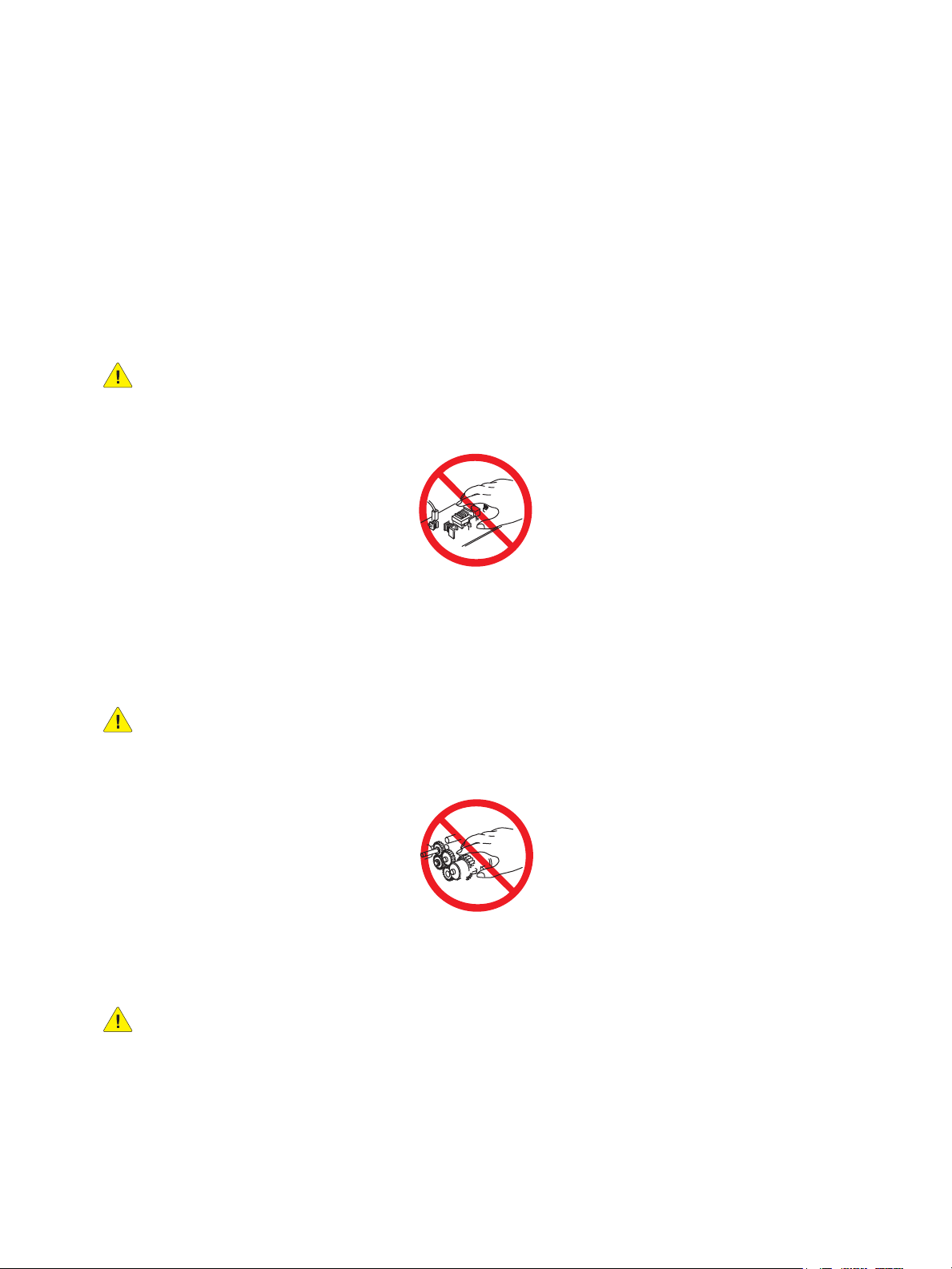
WARNING: Do not touch any electrical component unless you are instructed to do so by a service
procedure
.
Servicing Mechanical Components
When servicing mechanical components within the printer, manually rotate the Drive Assemblies,
Rollers, and Gears.
WARNING: Do not try to manually rotate or manually stop the drive assemblies while any motor
is running.
Servicing Fuser Components
WARNING: This printer uses heat to fuse the image to the media. During operating, the Fuser is
very hot. Allow the Fuser to cool before you attempt to service the Fuser or adjacent components.
1-6
Phaser 3320 and WorkCentre 3315/3325 Xerox Internal Use Only
Service Manual
Page 17

General Information
Health and Safety Incident Reporting
This section defines requirements for notification of health and safety incidents involving Xerox
products (equipment and materials) at customer locations worldwide. These requirements apply to
Xerox Corporation and its subsidiaries worldwide.
Objective
To enable prompt resolution of health and safety incidents involving Xerox products and to ensure
Xerox regulatory compliance.
Definitions
Incident:
An event or condition occurring in a customer account that has resulted in injury, illness or
property damage. Examples of incidents include machine fires, smoke generation, physical injury
to an operator or service representative. Alleged events and product conditions are included in this
definition.
Requirements
Initial Report:
1. Xerox organizations have established a process for individuals to report product incidents to Xerox
Environment Health & Safety within 24 hours of becoming aware of the event.
2. The information to be provided at the time of reporting is outlined in the Health and Safety
Incident Report form.
The Health and Safety Incident Report form used to report incidents involving Xerox products is
available on Xerox Global Service Net at https://www.xrxgsn.com/secure/main.pl?CatId=1789. If
you are unable to download the form, request a form when reporting the incident by phone,
electronic mail or Fax.
3. The initial notification may be made by any of the methods that follow:
– For incidents in North America and Developing Markets West (Brazil, Mexico, Latin American
North and Latin American South):
• Phone* Xerox EH&S at: +1-800-828-6571.
• Electronic mail Xerox EH&S at: usa.xerox.ehs@xerox.com.
• Fax Xerox EH&S at: +1-585-216-8817 [intelnet 8-219-8817].
– For incidents in Europe and Developing Markets East (Middle East, Africa, India, China and
Hong Kong):
• Phone* Xerox EH&S at: +44 (0) 1707 353434.
• Electronic mail Xerox EH&S at: ehs-europe@xerox.com.
• Fax Xerox EH&S at: +44 (0) 1707 353914 [intelnet 8 668 3914].
Note: Initial notification made by phone must be followed within 24 hours by a completed Health
and Safety Incident Report form sent to the indicated electronic mail address or fax number. If
sending a fax, please also send the original form by internal mail.
Xerox Internal Use Only Phaser 3320 and WorkCentre 3315/3325
Service Manual
1-7
Page 18

General Information
Responsibilities for resolution:
1. Business Groups / Product Design Teams responsible for the product involved in the incident shall:
a. Manage field bulletins, customer correspondence, product recalls, safety retrofits.
b. Fund all field retrofits.
2. Field Service Operations shall:
a. Preserve the Xerox product involved and the scene of the incident inclusive of any associated
equipment located in the vicinity of the incident.
b. Return any affected equipment/part(s) to the location designated by Xerox EH&S and/or the
Business Division.
c. Implement all safety retrofits.
3. Xerox EH&S shall:
a. Manage and report all incident investigation activities.
b. Review and approve proposed product corrective actions and retrofits, if necessary.
c. Manage all communications and correspondence with government agencies.
d. Define actions to correct confirmed incidents.
1-8
Phaser 3320 and WorkCentre 3315/3325 Xerox Internal Use Only
Service Manual
Page 19

Printer Symbols
Symbol Description
Warning or Caution:
Ignoring this warning could cause serious injury or even death.
Ignoring this caution could cause injury or damage to the property.
Hot surface on or in the printer. Use caution to avoid personal injury.
Caution: Electrostatic sensitive devices
Verify that you are properly grounded before making contact with the printer.
Ignoring this caution could cause damage to the property.
Do not touch components with this symbol as personal injury could result.
General Information
Do not burn the item.
It may take 40 minutes for the fuser to cool down.
Xerox Internal Use Only Phaser 3320 and WorkCentre 3315/3325
Service Manual
1-9
Page 20

General Information
Regulatory
Xerox has tested this product to electromagnetic emission and immunity standards. These standards
are designed to mitigate interference caused or received by this product in a typical office
environment.
European Union
The CE mark applied to this product symbolizes Xerox’s declaration of conformity with the following
applicable Directives of the European Union as of the dates indicated:
December 12, 2006: Low Voltage Directive 2006/95/EC
December 15, 2004: Electromagnetic Compatibility Directive 2004/108/EC
March 9, 1999: Electromagnetic Compatibility Directive 99/5/EC
This product, if used properly in accordance with the user's instructions, is neither dangerous for the
consumer nor for the environment.
To ensure compliance with European Union regulations, use shielded interface cables.
A signed copy of the Declaration of Conformity for this product can be obtained from Xerox.
1-10
Phaser 3320 and WorkCentre 3315/3325 Xerox Internal Use Only
Service Manual
Page 21

General Information
Introduction and Overview
The Phaser 3320 and WorkCentre 3315/3325 use a single-pass laser design, offering mono print
speeds of 33 to 37 ppm, and resolutions up to 1200 x 1200 dots-per-inch (dpi).
The Tray 1 is a 250-sheet multi purpose tray. The Bypass Tray is a 50 sheet tray that supports specialty
media, card stock, and envelopes. The Output Tray holds 150 sheets facedown.
The WorkCentre 3315/3325 combines a 1200 dpi scanner with the laser printer to provide copy, scan,
and print functions. Both models have a G3 Fax modem, Ethernet interface, and wireless capability to
provide networked copy, scan, and Fax functions.The WorkCentre 3315 model has an Automatic
Document Feeder (ADF), and the WorkCentre 3325 has a Duplex Automatic Document Feeder (DADF).
Technical Support Information
The Xerox Service Manual is the primary document used for repairing, maintaining, and
troubleshooting the printer. To ensure complete understanding of this product, participation in Xerox
Service Training is strongly recommended. To service this product, certification for this product is
required.
For updates to the Service Manual, Service Bulletins, knowledge base, etc., go to:
• Xerox Global Service Net - https://www.xrxgsn.com/secure/main.p
For further technical support, contact your assigned Xerox Technical Support for this product.
Xerox Internal Use Only Phaser 3320 and WorkCentre 3315/3325
Service Manual
1-11
Page 22

General Information
Parts of the Printer
Phaser 3320 Front View
1
2
8
3
7
4
6
5
9
11
No. Description No. Description
1. Output Tray 7. Tray 1
10
s3320-036
2. Control Panel 8. Bypass Tray
3. Control Board Cover 9. Bypass Tray Paper Extension
4. Front Cover 10. Bypass Tray Paper Width Guides
5. Paper Level Indicator 11. Output Support
6. Optional Tray 2
1-12
Phaser 3320 and WorkCentre 3315/3325 Xerox Internal Use Only
Service Manual
Page 23
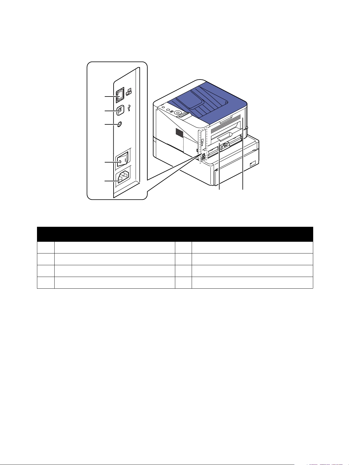
Phaser 3320 Rear and Side Views
1
2
3
4
5
General Information
6
No. Description No. Description
1. Network Port 5. Power Receptacle
2. USB Port 6. Duplex Unit
3. 5V Output 7. Rear Door
4. Power Switch
7
s3320-037
Xerox Internal Use Only Phaser 3320 and WorkCentre 3315/3325
Service Manual
1-13
Page 24
General Information
14
15
16
s3320-038
16
13
12
11
8
10
9
1
4
2
5
3
7
6
18
19
17
14
15
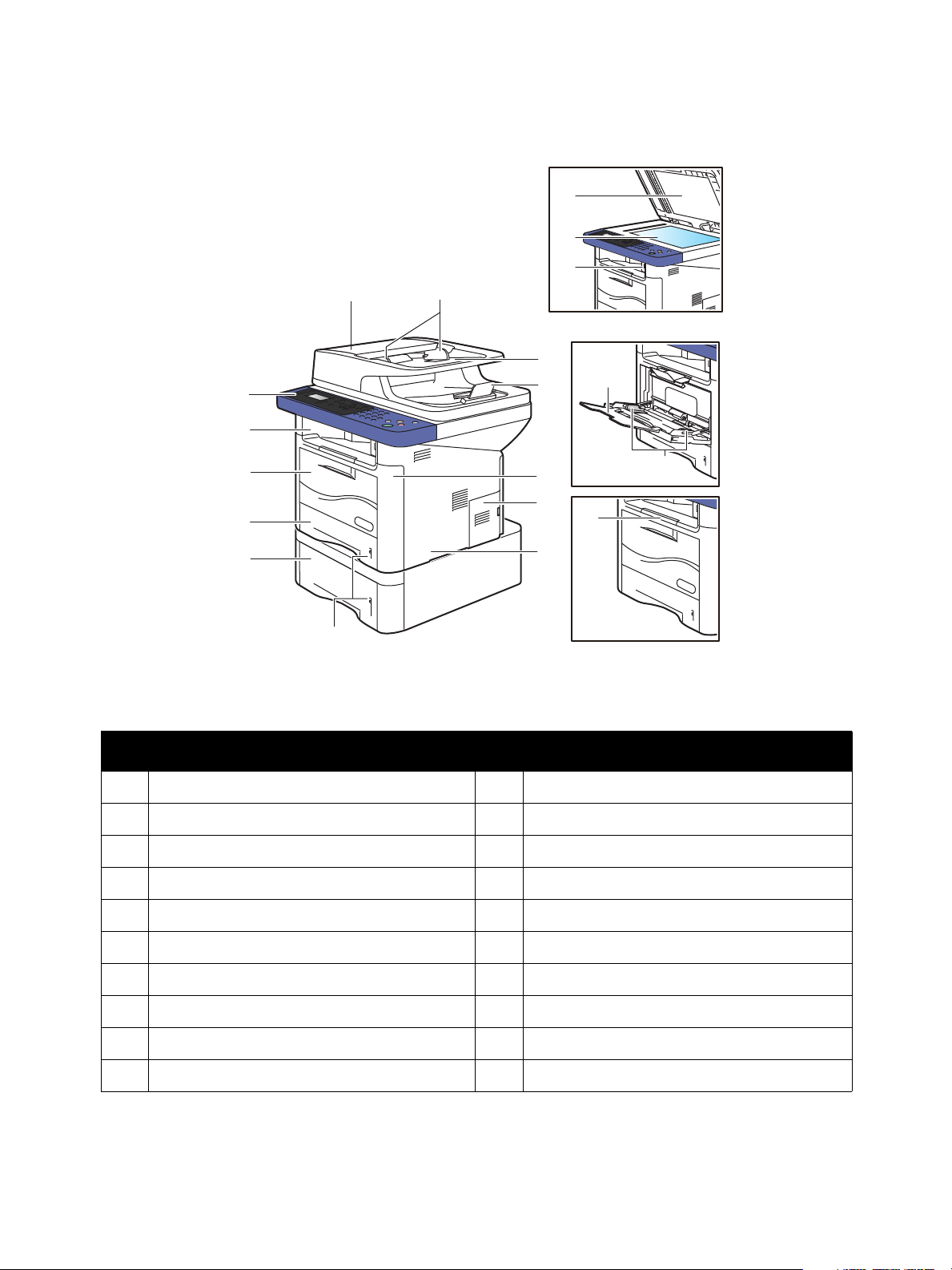
WorkCentre 3315/3320 Front Views
No. Description No. Description
1. Document Feeder Cover 11. Bypass Tray
2. Document Feeder Width Guide 12. Output Tray
3. Document Feeder Input Tray 13. Control Panel
4. Document Feeder Output Tray 14. Bypass Tray Extension
5. Front Cover 15. Bypass Tray Paper Width Guides
6. Control Board Cover 16. Output Tray Extension
7. Right Side Cover 17. Scanner Cover
8. Paper Level Indicators 18. Platen
9. Tray 2 (optional) 19. USB Thumbdrive Connector
10. Tray 1
1-14
Phaser 3320 and WorkCentre 3315/3325 Xerox Internal Use Only
Service Manual
Page 25
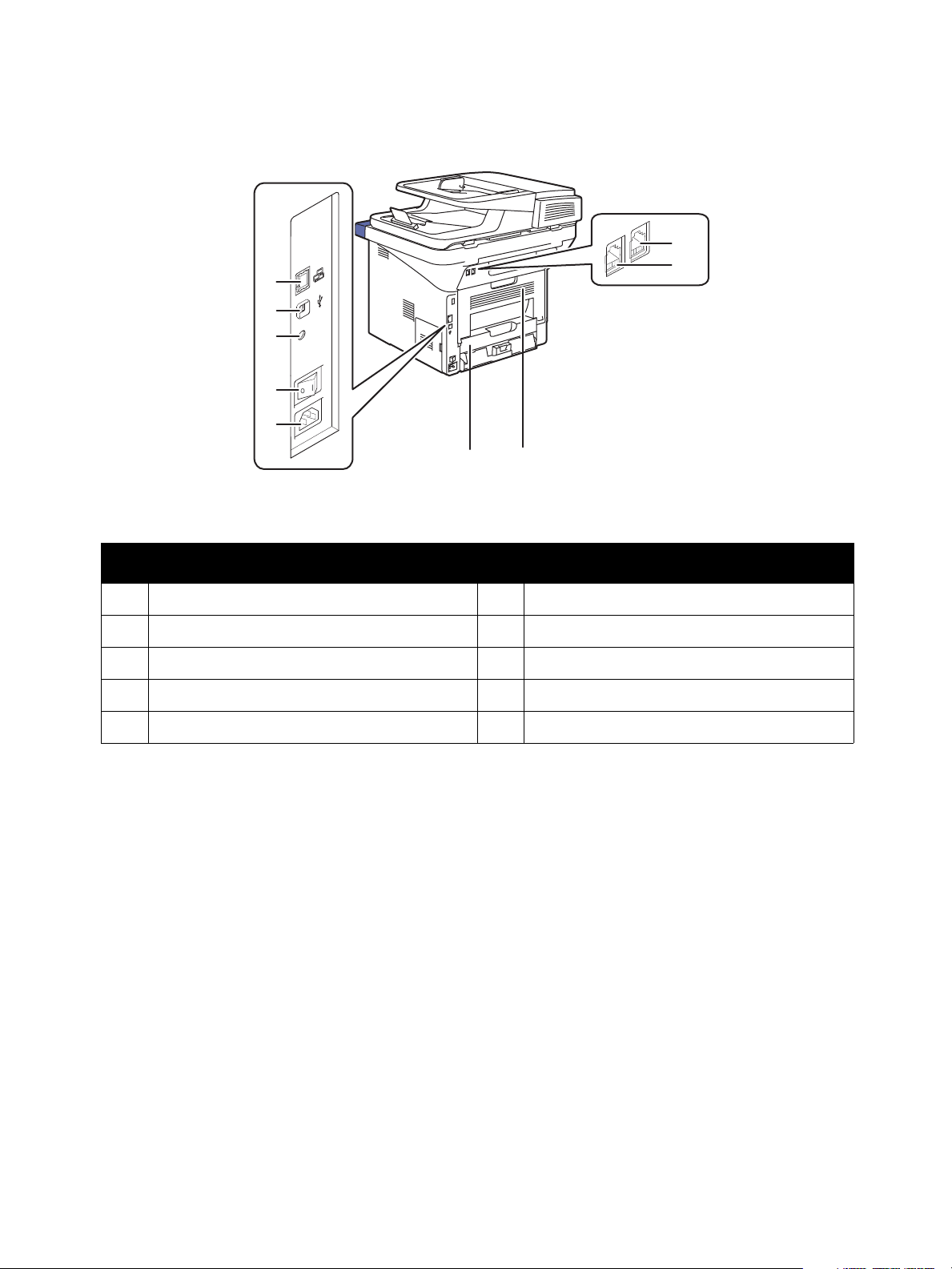
WorkCentre 3315/3320 Rear View
1
2
3
4
5
General Information
9
8
67
s3320-039
No. Description No. Description
1. Network Port 6. Duplex Assembly
2. USB Port 7. Rear Door
3. 5V Output 8. Telephone Line Socket
4. Power Switch 9. Telephone Extension Socket (EXT)
5. Power Receptacle
Xerox Internal Use Only Phaser 3320 and WorkCentre 3315/3325
Service Manual
1-15
Page 26

General Information
Control Panel
The Control Panel consists of multiple LEDs, a display, and several function buttons. These buttons are
used to navigate the menu system, perform functions, and select modes of operation.
Phaser 3320DN/I Control Panel Button Descriptions
Display
Screen
OK
Menu
Power
Save
3320
Arrows
Back
Stop
Status/Wireless LED
s3320-042
Item Description
Display Shows the current status and prompts during an operation.
Menu Enters menu mode and scrolls through the available menus.
OK Confirms the selection on the display.
Arrows Navigates available values by moving to the next or previous options.
Back Sends you back to the upper menu level.
Cancel Stops the current job.
Power Turn the power on and off with this button.
Status/Wireless LED Shows printer status and wireless network connection.
1-16
Phaser 3320 and WorkCentre 3315/3325 Xerox Internal Use Only
Service Manual
Page 27

WorkCentre 3315DN Control Panel Button Descriptions
3315
Copy
Scan
Display
Screen
Arrows
Arrows
Address
Book
OK Keypad
Pause/
Redial
Machine
Status
Job
Status
Menu
2-Sided
Email
Fax
Paper
Supply
Status/Wireless
LED
Clear All
Stop
Start
Cancel EntryManual Dial
Back
Power
Save
s3320-236
General Information
Item Description
Copy, Scan,
E-mail,and Fax
Display Screen Shows current status and prompts during operations.
Paper Supply Use to select the paper tray for a copy job.
Job Status Indicates the status of the printer – power and ready-to-print.
Machine Status Accesses machine information, status information, the machine serial number and
Arrow / OK (5) Navigate menus and useOK to set or confirm the current selection.
Address Book Store or search frequently used fax numbers and email addresses.
Manual Dial In Fax mode, opens the fax line. In E-mail mode, accesses commonly used e-mail
Keypad (14) Input and delete alphanumeric characters.
Power Saver When illuminated, indicates Low Power Mode. Press to return to Ready mode.
CA (Clear All) Clears all text, numbers or instructions.
Stop Stops the current job.
Start Starts the current job.
Back Move back to previous screen.
Menu Enters Menu mode and scrolls through the available menus.
System Switches the display to the System menus.
2 Sided Puts the printer in Manual Duplex mode.
Status/Wireless LED Shows printer status and wireless network connection.
Use these buttons to move to the top of each menu.
various reports to print.
addresses.The text available can be customized using CentreWare Internet Services.
When the user is making changes to a function (Copy, Scan, Print, or Fax), pressing the
Clear All button restores the previous settings and returns the menu to the top level of
that function.
Xerox Internal Use Only Phaser 3320 and WorkCentre 3315/3325
Service Manual
1-17
Page 28

General Information
3325
Copy
Scan
Display
Screen
Arrows
Arrows
Address
Book
OK Keypad
Pause/
Redial
Machine
Status
Job
Status
Menu
2-Sided
Email
Fax
Paper
Supply
Status/Wireless
LED
Interrupt
Printing
Clear All
Stop
Start
Cancel EntryManual Dial
Back
Power
Save
s3320-237
WorkCentre 3325DN/DNI Control Panel Button Descriptions
Item Description
Copy, Scan,
E-mail,and Fax
Display Screen Shows current status and prompts during operations.
Paper Supply Use to select the paper tray for a copy job.
Job Status Indicates the status of the printer – power and ready-to-print.
Machine Status Accesses machine information, status information, the machine serial number and
Arrow / OK (5) Navigate menus and useOK to set or confirm the current selection.
Address Book Store or search frequently used fax numbers and email addresses.
Manual Dial In Fax mode, opens the fax line. In E-mail mode, accesses commonly used e-mail
Keypad (14) Input and delete letters and numbers.
Interrupt Printing Interrupts the current job to run a more urgent job.
CA (Clear All) Clears all text, numbers or instructions.
Power Saver When illuminated, indicates Low Power Mode.
Stop Stops the current job.
Start Starts the current job.
Use these buttons to move to the top of each menu.
various reports to print.
addresses.The text available can be customized using CentreWare Internet Services.
Press to move to Ready from Energy Saver mode.
Back Move back to previous screen.
Menu Enters Menu mode and scrolls through the available menus.
2 Sided Puts the printer in Manual Duplex mode.
1-18
Phaser 3320 and WorkCentre 3315/3325 Xerox Internal Use Only
Service Manual
Page 29
Status/Wireless LED Indicates the wireless status of the printer.
Understanding the Status LED
The color of the Status LED indicates the machine’s current status.
Status Description
Status LED Off The machine is off-line.
Green Blinking • When the backlight slowly blinks, the machine is receiving data
from the computer.
• When the backlight blinks rapidly, the machine is printing data.
On • The machine is on-line and can be used.
• The machine is in power saver mode.
Red Blinking • A minor error has occurred and the machine is waiting for the
error to be cleared. Check the display message. When the
problem is cleared, the machine resumes. For some models that
do not support the display screen on the control panel, this
feature is not applicable.
• Small amount of toner is left in the cartridge. The estimated
cartridge life of toner is close. Prepare a new cartridge for
replacement. You may temporarily increase the printing quality
by redistributing the toner.
General Information
On • A minor error has occurred and the machine is waiting for the
error to be cleared. Check the display message. When the
problem is cleared, the machine resumes. For some models that
do not support the display screen on the control panel, this
feature is not applicable.
• Small amount of toner is left in the cartridge. The estimated
cartridge life of toner is close.
replacement. You may temporarily increase the printing quality
by redistributing the toner.
• The cover is opened. Close the cover.
• There is no paper in the tray. Load paper in the tray.
• The machine has stopped due to a major error.
a
Wireless LED
a. Wireless model only.
b. Estimated cartridge life means the expected or estimated Print Cartridge life, which indicates the average
capacity of print-outs and is designed pursuant to ISO/IEC 19752. The number of pages may be affected
by operating environment, printing interval, graphics, media type and media size. Some amount of toner
may remain in the cartridge even when red LED is on and the printer stops printing.
Blue On When the printer is connected to a wireless network, the Wireless
LED is illuminated.
b
Prepare a new cartridge for
Xerox Internal Use Only Phaser 3320 and WorkCentre 3315/3325
Service Manual
1-19
Page 30

General Information
s3320-044
Main Paper Path
Duplex Paper Path
Bypass Paper Path
Laser Unit
Developer
Tray 1
Duplex
Media Path
The media path throught the print engine is the same for all models
.
1-20
Phaser 3320 and WorkCentre 3315/3325 Xerox Internal Use Only
Service Manual
Page 31

General Information
Pick Up Roller
Retard Roller
Lift Pad
s3320-235
Feeder
Tray 1
The basic tray is located on front side of the machine and allows feeding of common paper. Paper size
is set using the Size Guides in each tray. Adjust the Paper length/width guides to match the paper size.
Paper Width Guide
Paper Length Guide
s3320-045
Pick Up / Retard Roller
When pickup takes place, the Pick Up Roller rotates to separate and transport the paper. The Pick Up
Roller rotates when the Pick Up Clutch is activated. The Retard Roller ensures that a single sheet of
paper is moved to the paper path, and the paper is moved as far as the Registration Roller by the Feed
Roller.
Registration Roller
When a sheet is fed from the tray to the toner transfer section, the registration of the sheet may not be
correctly maintained due to misalignment of lead edges in the tray. To avoid this problem, the lead
edge position needs to be aligned at the Registration Rollers before the sheet is fed in front of the
Transfer Belt, or in front of the BTRs.
By pressing the edge of the sheet fed out of the Tray 1 or Bypass Tray against the Registration Roller
that is locked, the lead edge position of the sheet is corrected.
Xerox Internal Use Only Phaser 3320 and WorkCentre 3315/3325
1-21
Service Manual
Page 32

General Information
Before the Registration Rollers are energized, the paper is advanced from the tray to the rollers. This
process aligns the leading edge of the page. By pushing the edge of the sheet against the Registration
Roller that is not turning, the lead edge of the sheet is registered.
Bypass Tray
The Bypass Tray can hold special sizes and types of print material, such as postcards, note cards, and
envelopes. It is useful for single page printing on letterhead or colored paper. It uses a 3 roller feeding
method to feed 50 sheets of general papers.
The media path from Tray 1 and Bypass Tray are the same. The sheets loaded in the Bypass Tray are
positioned nearer the Feed Roller, and have higher priority in feeding if both Tray 1 and the Bypass Tray
contain media.
s3320-046
Tray 2
When the optional tray is installed, it becomes Tray 2. Tray 2 has a 520 page capacity, a separate
driving mechanism, and uses the same design asTray 1.
ADF
Media is conveyed by the pick up module, and driven through the paper path by torque from the
driving module. When the sheet reaches scanner home position, it is scanned. When the scan
completes, the sheet is ejected to the output tray by the exit roller. The exit roller is driven by torque
from the ADF Motor.
1-22
Phaser 3320 and WorkCentre 3315/3325 Xerox Internal Use Only
Service Manual
Page 33

General Information
Exit Roller
Scanner Home Position
Takeaway Roller
Nudger Roller
Pick Up Module
Feed Roller
Feed Sensor Document Sensor
ADF Separator Pad
: Paper Transfer
: Paper Sensors
s3320-238
s3320-239
Duplex Unit
The Duplex Unit is standard with all models of these printers. Usable papers are A4, letter, and legal
size paper. The Duplex Unit is easily removed for clearing paper jams at both the front and rear of the
printer. To clear paper jams at the front or rear of the printer, pull the Duplex Unit out of the printer.
Xerox Internal Use Only Phaser 3320 and WorkCentre 3315/3325
1-23
Service Manual
Page 34

General Information
s3320-240
Charge
Roller
Drum Cartridge
Drum OPC
Laser Unit
Doctor Blade
Charge Cleaning Roller
Cleaning
Blade
Paper
Path
Pressure
Roller
Heat Roller
Transfer
Roller
Developer Roller
Supply Roller
Agitator 1
Agitator 2
Fuser
Print Process
Print Cartridge
This printer uses a Laser Unit (LSU), single Print Cartridge, Transfer Roller, and Fuser for mono printing.
The Print Cartridge consists of drum unit, development unit and toner supply.
• Operating condition: Temp 1 0 ~30
• Developing Method: Non magnetic single element contact method
• Toner: Non magnetic, single element toner
• The life span of toner (ISO 19752 pattern / A4 standard)
– Initial toner: 2.3K WorkCentre 3315
– Initial toner 5.0K WorkCentre 3325 / Phaser 3320
– Sales toner: 2.3K and 5.0K WorkCentre 3315
– Sales toner 5.0K and 11.0K WorkCentre 3325 / Phaser 3320
• Toner Residual Sensor: Dot count with CRUM(CRU Monitor)
• OPC Cleaning: Collect the toner with cleaning blade
• Handling of wasted toner: Collect wasted toner in the cleaning frame
• Print Cartridge: CRUM identifier.
° C (50~86° F), Humidity 20~85% RH
Print Cartridge Components
Item Item
Charge Roller Supply Roller
Drum OPC Charge Cleaning Roller
Cleaning Blade Agitator 1
Doctor Blade Agitator 2
Developer Roller
1-24
Phaser 3320 and WorkCentre 3315/3325 Xerox Internal Use Only
Service Manual
Page 35

General Information
Fuser
The Fuser consists of a halogen lamp, heat roller, pressure roller, thermistor and thermostat. It sticks
the toner on a paper by heat and pressure to complete the printing job.
Thermistor
Thermostat
Heat Roller
Pressure Roller2
Pressure Roller
Halogen Lamp
s3320-261
•Thermostat
When the heat lamp overheats, the Thermostat cuts off the main power to prevent over- heating.
– Thermostat Type: Non- Contact type THERMOSTAT
–Control Temperature: 170
°C ± 5 C°
•Thermistor
The Thermistor is a temperature detecting sensor.
– Temperature Resistance: 78k ohms (180
°C)
• Heat roller
The heat roller transfers the heat from the lamp to apply heat on the paper.
The surface of the heat roller is coated with Teflon, so toner does not stick to the surface.
• Pressure roller
A pressure roller mounted under a heat roller that is made of a silicon resin, and the surface also is
coated with Teflon. When a paper passes between a heat roller and a pressure roller, toner
adheres to the surface of a paper permanently.
•Halogen Lamp
– Voltage 120 V: 115 ± 5%
Voltage 220 V: 230 ± 5%
– Capacity: 850 Watt ± 25 W
Xerox Internal Use Only Phaser 3320 and WorkCentre 3315/3325
Service Manual
1-25
Page 36

General Information
s3320-264
Photo Diode
Laser Diode
Driver Circuit
Protector Panel
Laser Diode Motor Driver
Polygon Mirror
OPC Drum
Polygon Motor
Laser Scanning Unit (LSU)
It is the core part of the LBP which switches from the video data received to the controller to the
electrostatic latent image on the OPC drum by controlling laser beam, exposing the OPC drum, and
turning principle of the polygon mirror. The OPC drum is turned with the paper feeding speed. The
/HSYNC signal is created when the laser beam from LSU reaches the end of the polygon mirror, and the
signal is sent to the controller.
The controller detects the /HSYNC signal to adjust the vertical line of the image on paper. In other
words, after the /HSYNC signal is detected, the image data is sent to the LSU to adjust the left margin
on paper. The one side of the polygon mirror is one line for scanning.
1-26
Phaser 3320 and WorkCentre 3315/3325 Xerox Internal Use Only
Service Manual
Page 37

General Information
s3320-245
Drive
•Main Drive Assembly
A gear set used to transfer drive from the Main Drive Motor to feed media through the media
path.
Xerox Internal Use Only Phaser 3320 and WorkCentre 3315/3325
Service Manual
1-27
Page 38

General Information
Main Motor
Rear Cover
Open Switch
Main Fan
LVPS Fan
Bypass Tray
Clutch
Pick Up
Clutch
Registration
Clutch
Coupler Bar
s3320-249
Electrical
The electrical system consists of the Main Board, Control Panel Board, HVPS, LVPS, Power Switch
Assembly, ADF/DADF Board, FAX, and Wireless Interface Board.
• Main Board
The Main Board controls all modules required to print, that is, LSU, HVPS, SMPS, FAN, Fuser, FAX,
and Scanner. The controller receives print data from the host through network or USB Port or fax,
Scanner. It takes this information and generates printable video bitmap data. Engine and video
control are combined.
• Control Panel Board - displays the status of the system using 16 x 2line LCD in response to user
actions or the Main controller.
• HVPS - supplies high voltage for the developing Process. The High Voltage is controlled by the
PWM signal from the CPU.
• LVPS - makes +5V and +24V DC from 220V or 110 AC.
• Power Switch Assembly - controls power to the printer.
• ADF/DADF Board - provides the interface between the ADF/DADF and the Main Board.
• FAX Board - provides the FAX interface to the printer.
• WLAN Board - the WLAN board provides a wireless Ethernet interface.
Optional Memory
• Optional Memory DIMM for WorkCentre 3325 only
A 256 MB, SO-DIMM Board is available to increase system memory on the Main Board. Additional
memory is used for operating system, system application programs, and print data storage.
Locations of Phaser 3320 Electrical Components
The following illustration shows the location of electrical components in the Phaser 3320.
1-28
Phaser 3320 and WorkCentre 3315/3325 Xerox Internal Use Only
Service Manual
Page 39

General Information
Locations of WorkCentre 3315/3325 Electrical Components
The following illustration shows the location of electrical components in the WorkCentre 3315/3325.
Main Motor
Rear Cover
Open Switch
Coupler Bar
Mid Fan
Registration
Clutch
Bypass Tray Clutch
Main Fan
Pick Up Clutch
LVPS Fan
(110V machines only)
s3320-248
Sensors
The printer contains sensors of various types that perform a variety of functions. Some sensors track
media along the media path to detect jams. Other sensors detect the Print Cartridge, monitor toner
density, stop printer activity if the Rear Door is open (interlock) and monitor fusing temperature.
Xerox Internal Use Only Phaser 3320 and WorkCentre 3315/3325
Service Manual
1-29
Page 40

General Information
s3320-246
Feed Sensor
Paper Empty Sensor
Outbin Full Sensor
Exit Sensor
Registration Sensor
Bypass Tray Paper Empty Sensor
Scanner
Home Position
Sensor
Feed Sensor
Paper Empty Sensor
Outbin Full
Sensor
Exit Sensor
Registration Sensor
Bypass Tray Paper Empty Sensor
s3320-247
Locations of Phaser 3320 Sensors
Locations of WorkCentre 3315/3325 Electrical Components
1-30
Phaser 3320 and WorkCentre 3315/3325 Xerox Internal Use Only
Service Manual
Page 41

General Information
Maintenance Items
Routine maintenance items are parts or assemblies that require periodic replacement. These items are
typically customer replaceable (CRU).
The listed items have limited life and require periodic replacement.
Item Print Life
Pick Up Roller Up to 90,000 pages
Retard Roller Up to 60,000 pages
Transfer Roller Up to 100,000 pages
Fuser (not customer replaceable) Up to 90,000 pages
ADF Feed Roller Assembly Approximately 20,000 sheets
ADF Separator Pad Assembly Approximately 20,000 sheets
DADF Feed Roller Assembly Approximately 80,000 sheets
Print life is based on “typical” office printing and 5% coverage per color on 24 lb. paper. Print life
figures are not guaranteed and varies depending on usage habits. Imaging Unit print life is based on 3page jobs using letter-size paper.
Consumables
Consumables consist of a single Print Cartridge. The Print Cartridge (except starter cartridges) has a
CRUM (Customer Replaceable Unit Monitor) to record regional and toner usage information. The
CRUM maintains a count of the amount of toner consumed. When the count reaches set values,
warning and error messages appear to notify the user when near and end of life status is reached.
Life ratings are based on A-size sheets at 5% coverage.
Print Cartridge Phaser 3320 WorkCentre 3315MFP WorkCentre 3325MFP
Starter Capacity 5,000 pages 2,300 pages 5,000 pages
Standard Capacity 5,000 pages 2,300 pages 5,000 pages
High Capacity 11,000 pages 5,000 pages 11,000 pages
Starter capacity cartridges are packaged with the printer when shipped from the factory. These starter
cartridges are not available for order.
Xerox Internal Use Only Phaser 3320 and WorkCentre 3315/3325
Service Manual
1-31
Page 42

General Information
Specifications
Configurations
The following table details the Phaser 3320DN/DNI configurations.
Fea tures Phaser 3320DN/DNI
Processor Speed 600 MHz
Memory Configuration 128 MB
Maximum Memory 384 MB
Flash Memory No
Print Speed (A4-size) from Tray 1
Simplex
Phaser 3320DNI Duplex
37 ppm
17 ipm
First Print Output Time As fast as 6.5 seconds
Print Resolutions (dpi)
Standard
a
High
High Speed USB 2.0 Support Standard
Wireless 3320DNI model only
Tray 1 250 sheets
Bypass Tray 50 sheets
Output Tray 150 sheets
Tray 2 (Optional tray) 520 Sheets
Duplex Standard
a. When printing in high resolution mode, printing speed may be reduced due to image quality adjustment.
Printing speed may also be reduced depending on documents
600 x 600
1200 x 1200
1-32
Phaser 3320 and WorkCentre 3315/3325 Xerox Internal Use Only
Service Manual
Page 43

General Information
The following table details the WorkCentre 3315/3325DN/DNI configurations
Fea tures WorkCentre 3315DN WorkCentre 3325DN/DNI
Processor Speed 360 MHz 600 MHz
Memory Configuration
Standard
Maximum Memory
Flash Memory 16 MB 32 MB
Print Speed (A4-size)
Simplex
Duplex
Duplex Standard Standard
Bypass Tray
a
Tray 1 250 Sheets 250 Sheets
Output Tray 150 Sheets 150 Sheets
128 MB
384 MB
33 ppm
15 ipm
256 MB
768 MB
37 ppm
17 ipm
50-sheets 50-sheets
Tray 2 (Optional tray) 520 Sheets 520 Sheets
ADF/DADF
Capacity 50 sheets 50 sheets
2-sided document scanning No Yes (reversing)
Print Resolutions (dpi)
Standard 600 x 600 600 x 600
High
b
1200 x 1200 1200 x 1200
Interfaces
High Speed USB 2.0 Type A
Standard (1 port) Standard (2 ports)
Support
High Speed USB 2.0 Type B
Standard (1 port) Standard (1 port)
Support
Ethernet Interface 10/100 Base-TX 10/100 Base-TX
Wireless Interface IEEE802.11b/g None WorkCentre 3325DNI model only
a. Bypass Tray has priority for feeding paper. Paper is fed from Bypass Tray if there is paper in both Tray 1
and Bypass tray. The printer cannot detect which tray has paper.
b. When printing in high resolution mode, printing speed may be reduced due to image quality adjustment.
Printing speed may also be reduced depending on documents
Xerox Internal Use Only Phaser 3320 and WorkCentre 3315/3325
Service Manual
1-33
Page 44

General Information
Paper Handling
Item Phaser 3320 WorkCentre 3315/3325
Standard Capacity 250-sheet Cassette Tray, 50-sheet
2
Max. Capacity
Multi Purpose Tray @80g/m
850 sheets @80g/m
2
250-sheet Cassette Tray, 50-sheet
Multi Purpose Tray @80g/m
850 sheets @80g/m
2
Printing Max. Size 216 x 356 mm (8.5" x 14") 216 x 356 mm (8.5" x 14")
Min. Size 76 x 127 mm (3.0" x 5.0") 76 x 127 mm (3.0" x 5.0")
Bypass Tray
Capacity Plain Paper
50 sheets @80 g/m
2
50 sheets @80 g/m
2
Envelope 5 sheets 5 sheets
Media sizes A4, A5, A6, Letter, Legal, Folio,
Oficio, Executive, ISO B5, JIS B5,
3"x5", Envelope (Monarch, No.10,
DL, C5, C6), Custom
Media Type Plain, Thin, Thick, Thicker, Cotton,
Colored, Envelope, Transparency,
Pre-Printed, Recycled, Labels,
Bond, Card stock, Archive
Media Weight
16~58 lb (60 to 220 g/m
2
) 16~58 lb (60 to 220 g/m2)
A4, A5, A6, Letter, Legal, Folio,
Oficio, Executive, ISO B5, JIS B5,
3"x5", Envelope (Monarch, No.10,
DL, C5, C6), Custom
Plain, Thin, Thick, Thicker, Cotton,
Colored, Envelope, Transparency,
Pre-Printed, Recycled, Labels,
Bond, Card stock, Archive
Sensing Paper Empty Paper Empty
Tray 1
Capacity
250 sheets @80 g/m
2
Media sizes A4, A5, A6, Letter, Legal, Folio,
Oficio, Executive, ISO B5, JIS B5,
Custom
Media Type Plain Paper, Thin, Thick, Recycled,
Bond, Cardstock, Archive
Media Weight
16~43 lb (60 to 163 g/m
2
) 16~43 lb (60 to 163 g/m2)
250 sheets @80 g/m
A4, A5, A6, Letter, Legal, Folio,
Oficio, Executive, ISO B5, JIS B5,
Custom
Plain Paper, Thin, Thick, Recycled,
Bond, Cardstock, Archive
2
Sensing Paper Empty Paper Empty
Optional Tray 2
Capacity
520 sheets @80 g/m
550 sheets @75 g/m
2
2
Media sizes A4, A5, A6, Letter, Legal, Folio,
Oficio, Executive, ISO B5, JIS B5
Media Type Plain Paper, Thin, Thick, Recycled,
Bond, Cardstock, Archive
Media Weight
16~43 lb (60 to 163 g/m
2
) 16~43 lb (60 to 163 g/m2)
520 sheets @80 g/m
550 sheets @75 g/m
A4, A5, A6, Letter, Legal, Folio,
Oficio, Executive, ISO B5, JIS B5
Plain Paper, Thin, Thick, Recycled,
Bond, Cardstock, Archive
2
2
Sensing Paper Empty Paper Empty
Output Stacking
2
1-34
Phaser 3320 and WorkCentre 3315/3325 Xerox Internal Use Only
Service Manual
Page 45

General Information
Item Phaser 3320 WorkCentre 3315/3325
Capacity Face-Down
Face-Up 1 sheet 1 sheet
Output Full Sensing Yes Yes
Automatic Duplex
Supporting Built-in Built-in
Media Sizes A4, Letter, Oficio, Folio, Legal A4, Letter, Oficio, Folio, Legal
Media Types Plain Paper, Thin, Thick, Recycled,
Media Weight
ADF/DADF
Capacity
2-sided Document Scanning N/A WorkCentre 3325 only
Paper Size
Paper Weight
Feed ing Order
150 sheets @80 g/m
Bond, Cardstock, Archive
16~32 lb (60 to 120 g/m2) 16~32 lb (60 to 120 g/m2)
No
No Width: 142~216mm (5.6"~8.5")
No WorkCentre 3315: 16~28 lbs.
No Top to bottom feed
2
150 sheets @80 g/m
Plain Paper, Thin, Thick, Recycled,
Bond, Cardstock, Archive
50 sheets @80 g/m
Length: 148~356mm (5.8"~14.0")
WorkCentre 3325: 12.5~28 lb
2
2
Printing Specifications
Characteristic Specification
Printing Technology Recording System: Laser electro-photographic system using OPC Drum and direct
transfer to the media.
Exposure System: Laser printhead
Transfer System: Finished image is transferred onto the media
Fusing System: Thermal fusing system by belt
Color Medium Black Print Cartridge
Print-Quality Mode Standard 600 x 600
Enhanced 1200 x 1200
Non-printable Area Envelope 10 mm (0.4”) from edge (top, bottom, left, and right)
Other Media 4 mm (.16”) from edge (top, bottom, left, and right)
Printer Life Phaser 3320DN
Phaser 3320DNI
WorkCentre 3315
WorkCentre 3325
War m-Up Tim e
From Sleep Mode
Phaser 3320DN
Phaser 3320DNI
WorkCentre 3315
WorkCentre 3325
170,000 pages or 5 years (whichever comes first)
220,000 pages or 5 years (whichever comes first)
170,000 pages or 5 years (whichever comes first)
220,000 pages or 5 years (whichever comes first)
35 seconds
35 seconds
As fast as 35 seconds
As fast as 35 seconds
Xerox Internal Use Only Phaser 3320 and WorkCentre 3315/3325
Service Manual
1-35
Page 46

General Information
Characteristic Specification
Operating System Windows 2000, XP(32/64bits), Vista(32/64bits), 2003 Server
(32/64bits), 2008 Server(32/64bits), 7(32/64bits),
2008 Server R2(64bits)
Macintosh OS 10.4 to 10.7
Linux RedHat Enterprise Linux WS 4,5(32/64 bit)
Fedora Core 2 ~10 (32/64 bit)
SuSE Linux 9.1 (32 bit)
OpenSuSE 9.2, 9.3, 10.0, 10.1, 10.2, 10.3, 11.0,
11.1 (32/64 bit)
Mandrake 10.0, 10.1 (32/64 bit)
Mandriva 2005, 2006, 2007, 2008 (32/64 bit)
Ubuntu 6.06, 6.10, 7.04, 7.10, 8.04, 8.10 (32/64 bit)
SuSE Linux Enterprise Desktop 9, 10 (32/64 bit)
Debian 3.1, 4.0, 5.0 (32/64 bit)
* Assumes a 30 day month of printing.
Scanning Specifications
Characteristic Specifications
Scan Driver WIA, TWAIN
Scanning Mode Platen Mode: Scan document using the document glass
Constant Velocity Transport (CVT) Mode: Scan document via the Automatic
Document Feeder (ADF/DADF)
Scan Method Color CIS
Compatibility Twain, WIA
Color Mode Mono, Gray, or Color
Halftone 256 Levels
Scan Speed
Line art, Halftone
(mono), Gray (mono)
Color
Resolution Optical: 600 x 600 dpi
Scan Size
WorkCentre 3315: 20 ipm @ 300 dpi
WorkCentre 3325: 24 ipm @ 300 dpi
WorkCentre 3315: 6 ipm @ 300 dpi
WorkCentre 3325: 8 ipm @ 300 dpi
Enhanced: 4800 * 4800 dpi
Maximum Document Width Max. 216 mm (8.5 in.)
Effective Scan Width Max. 208 mm (8.2 in.)
1-36
Phaser 3320 and WorkCentre 3315/3325 Xerox Internal Use Only
Service Manual
Page 47

Characteristic Specifications
Effective Scan Length Platen: A4
ADF: 356 mm
Scan Depth
General Information
Color
Mono
Scan To
Client (TWAIN/WIA)
Email
Email Protocol
Fold er
Home
Network Scanning Protocol
Mailbox
USB
24 bits
1 bit for Line art & Halftone
8 bits for Grayscale
Ye s
Ye s
SMTP
Yes (WorkCentre 3325 only)
No
FTP/SMB (WorkCentre 3325 only)
No
Ye s
Copy Specifications
Characteristic Specifications
Copy Speed (A4) WorkCentre 3315: 31 ppm
WorkCentre 3325: 35 ppm
First Copy Output Time WorkCentre 3315: < 12 seconds
WorkCentre 3325: < 10 seconds
Resolution 600 x 600 dpi
Copy Mode Black & White
Output Type Standard, Enhanced (Best)
Ori g i n al Type Text , Te xt/P h o t o, P h ot o
Reduce/Enlarge 25% - 400% for Platen
25% - 100%for ADF
Output Collated, Not Collated
Reduce/Enlarge from Glass 25% to 400%
Reduce/Enlarge from ADF/DADF 25% to 400%
Reduction/Enlargement (Presets) 9 + custom
Manual Duplex WorkCentre 3315 only
Xerox Internal Use Only Phaser 3320 and WorkCentre 3315/3325
Service Manual
1-37
Page 48

General Information
Characteristic Specifications
Max Copy Size (Platen) A4
Max Copy Size (ADF/DADF) Legal
Copy to Mailbox No
Automatic Background Suppression Yes
Darkness Control Yes
ID Card Copy Yes
Margin Shift Yes
Book Copy WorkCentre 3325 only (Platen only)
Book Copy with Center Erase WorkCentre 3325 only (Platen only)
Edge Erase WorkCentre 3325 only
Transparencies No
Booklet WorkCentre 3325 only
Multiple Up (N to 1) 2-up, 4-up
Clone Yes
Job Interrupt WorkCentre 3325 only
Job Build Yes
Photo Mode Yes
Fax Specifications
Characteristic Specifications
Communication Mode ITU-T G3 ECM
Communication System PSTN/PABX
Delayed Send Yes
Modem Speed 33.6kbps
TX Speed Approximately 3 seconds (Mono/Standard/ECM-
MMR, @ ITU-T G3 No. 1)
Broadcast/Group Dialing Up to 209
Compression MH/MR/MMR/JBIG/JPEG
Color Fax Yes (TX only)
ECM Yes
External Phone Interface Yes
Key Volume Adjust Yes
Last Number Redial Yes
Memory Receive Yes
1-38
Phaser 3320 and WorkCentre 3315/3325 Xerox Internal Use Only
Service Manual
Page 49

General Information
Characteristic Specifications
Mono Resolution
Std.
Fine
S. Fine
Off-hook Dial Yes
Phone Book Yes
Speed Dial 200 locations
Mail Box No
Receive Mode Fax, TEL, Ans/Fax, DRPD
Ring Volume Adjust Yes
RTI Yes
Secure Fax Yes
Send Confirmation Yes
Send Receive Reporting Journal/Printout Yes
Speaker Volume Adjust Yes
System Data List Print Out Yes
To n e/ P u l se Ye s
Fax Memory 4 MB
TTI Yes
Fax Forward to FAX Yes (On/Off), both Sent and Received
Fax Fo rward to Emai l Yes
Fax Address Book Up to 200 Speed Dial and up to 6 Group Dial
203 x 98 dpi
203 x 196 dpi
300 x 300n dpi
numbers are stored. Group Dial Numbers may have
up to 200 Fax numbers associated with each group;
however, the total number of allowable Fax numbers
for all groups is 200.
Electrical Specifications
Characteristic Phaser 3320 WorkCentre 3315/3325
Power Supply Voltage/Frequency
Line Voltages 110-127 VAC ± 10%
220-240 VAC ± 10%
Frequency Range 50/60 Hz ± 3 Hz 50/60 Hz ± 3 Hz
Current Capacity 110 V Engine: < 8 A
220 V Engine: < 4 A
Power Consumption (with all options, 110 or 220 V)
Deep Sleep 2.5 W or less 2.5 W or less
Power Saver Mode 8 W or less 10 W or less
Xerox Internal Use Only Phaser 3320 and WorkCentre 3315/3325
110-127 VAC ± 10%
220-240 VAC ± 10%
110 V Engine: < 8 A
220 V Engine: < 4 A
Service Manual
1-39
Page 50

General Information
Characteristic Phaser 3320 WorkCentre 3315/3325
Standby Mode (Fuser On) 37 W or less 37 W or less
Continuous Printing 310W or less 310W or less
Environmental Specifications
Image quality is guaranteed in the optimum ranges for temperature and humidity.
Characteristic Specification
Operating Temperature 10 to 32° C (50 to 90° F)
Operating Humidity
(% RH)
Operating Altitude 0 to 2,500 meters (8,200 feet)
Acoustic Noise LWA(B) Sound Power Level (B) Sound Pressure (dBA)
Printing
Phaser 3320DN
Phaser 3320DNI
WorkCentre 3315
WorkCentre 3325
Copying
WorkCentre 3315
WorkCentre 3325
Standby
Phaser 3320
WorkCentre 3315
WorkCentre 3325
Sleep Back Ground Level Back Ground Level
Average Power
Consumption
Operating < 420 W WorkCentre 3315: < 600 W
Standby 37 W or less 37 W or less
Sleep < 8 W < 10 W
Power Off < 0.7 W < 0.7 W
20 to 80% RH
5.1 B
5.2 B
5.2 B
5.3 B
5.4 B
5.4 B
•<2.6 B
• 2.6 B for first 30 pages printing) /
3.0 B (after 30 pages printing)
• 2.6 B (for first 30 pages printing) /
3.0 B (after 30 pages printing)
Phaser 3320 WorkCentre 3315/3325
51dBA
52 dBA
52 dBA
53 dBA
54 dBA
54 dBA
• <26dBA
• 26 dBA (for first 30 pages printing)
/ 30dBA (after 30 pages printing)
• 26 dBA (for first 30 pages printing)
/ 30dBA (after 30 pages printing)
WorkCentre 3325: < 600 W
1-40
Phaser 3320 and WorkCentre 3315/3325 Xerox Internal Use Only
Service Manual
Page 51

Physical Dimensions and Clearances
Phaser 3320DN/I Dimensions
Characteristic Measurement
Height 257 mm (10.1 in.)
Width 366 mm (14.4 in.)
Depth 368 mm (14.5 in.)
Weight (base printer with consumables)
• Phaser 3320DN
• Phaser 3320DNI
WorkCentre 3315 Dimensions
• 11.2 kg (25.79 lbs.)
• 11.2 kg (25.79 lbs.)
General Information
Characteristic Measurement
Height 417 mm (16.4 in.)
Height with 250-Sheet Feeder 563 mm (22.1 in.)
Width 424 mm (16.7 in.)
Depth 422 mm (16.6 in.)
Weight (base printer with consumables) 18.2 kg (40.12 lbs.)
WorkCentre 3325 Dimensions
Characteristic Measurement
Height 447 mm (17.6 in.)
Height with 250-Sheet Feeder 593.4 mm (23.4 in.)
Width 469 mm (18.5 in.)
Depth 458 mm (18.0 in.)
Weight (base MFP with consumables) 20.09 kg (44.29 lb.)
Xerox Internal Use Only Phaser 3320 and WorkCentre 3315/3325
Service Manual
1-41
Page 52

General Information
10 cm
(3.9 in.)
48.3 cm
(18.8 in.)
10 cm
(3.9 in.)
10 cm
(3.9 in.)
s3320-122
10 cm
(3.9 in.)
10 cm
(3.9 in.)
10 cm
(3.9 in.)
48.3 cm
(18.8 in.)
10 cm
(3.9 in.)
10 cm
(3.9 in.)
10 cm
(3.9 in.)
s3320-121
76.2 cm
(30 in.)
100 cm
(39.4 in.)
62.4 cm
(24.6 in.)
100 cm
(39.4 in.)
62.4 cm
(24.6 in.)
90.9 cm
(35.8 in.)
48.3 cm
(18.8 in.)
Phaser 3320 Minimum Clearances
WorkCentre 3315/3325 Minimum Clearances
1-42
Phaser 3320 and WorkCentre 3315/3325 Xerox Internal Use Only
Service Manual
Page 53

General Information
Max Tilt
7mm Max
Mounting Surface Specifications
Mounting surface flatness must be within the specified range. The printer must not be tipped or tilted
more than 7 mm. Failure to adhere to the mounting specifications void all guarantees of print-quality
and/or performance.
Right Hand Side
5mm Max
Max Flex
Xerox Internal Use Only Phaser 3320 and WorkCentre 3315/3325
Service Manual
1-43
Page 54

Error Troubleshooting
In this chapter...
• Introduction
• Servicing Instructions
• Service Mode
• Phaser 3320 Service Mode
• WorkCentre 3315/3325 Service Mode
• Error Messages and Troubleshooting
• Other Errors
2
Xerox Internal Use Only Phaser 3320 and WorkCentre 3315/3325
Service Manual
2-1
Page 55

Error Troubleshooting
Introduction
This chapter describes error messages displayed on the Control Panel or listed on the Error History
page. Also discussed are Service Diagnostics used to test system operation and troubleshooting
procedures to correct problems. Troubleshooting print quality problems is covered in Chapter 3, Image
Quality.
Errors are tracked and reported in a number of ways. The two types of error reporting discussed in this
section include:
• Error messages and codes displayed on the Control Panel
• Engine (fatal) and Jam Error logs displayed on the Control Panel or listed on the Error History
Report
Monitoring Supplies Life
If you experience frequent paper jams or printing problems, check the number of pages the machine
has printed or scanned. Replace the corresponding parts, if necessary.
Accessing Supplies Information on the Phaser 3320
1. On the Control Panel, press Menu > Information.
2. Select the option that you want and press the OK button.
– Demo page: You can print the demo page to check whether your machine is printing properly
or not.
– Configuration: You can print a report on the machine’s overall configuration to show various
SW version and current machine settings status.
– Supplies Information: You can print the supplies’ information page to show consumable unit
life status and toner status.
Accessing Supplies Information on the WorkCentre 3315/3325
1. On the Control Panel, press the Machine Status button, then using the arrow buttons select
System Setup > Maintenance > Supplies Life.
Note: If asked for a password, use the keypad to enter the first password character and then press
the Right Arrow button. Repeat this button sequence to enter the password, and then press OK.
The default password is 1111.
2. Select the option you want and press the OK button.
Supplies Info: Prints the supply information page.
To ta l: Displays the total number of pages printed.
ADF Scan: Displays the number of pages printed by using the document feeder.
Platen Scan: Displays the number of pages scanned by using scanner glass.
3. Press the Stop/Clear button to return to ready mode.
2-2
Phaser 3320 and WorkCentre 3315/3325 Xerox Internal Use Only
Service Manual
Page 56

Error Troubleshooting
Initial Actions
Some problems are easy to resolve. Use these steps in an attempt to quickly isolate the problem.
1. Turn Off the printer, wait 10 seconds, then turn On the printer. This often solves problems related
to power transients, ESD, and software errors.
2. If a message appears on the Control Panel, see “Messages, Codes, and Procedures” on page 3-5
for specific procedures related to error messages.
3. Check the power cord. Is the power cord plugged into the printer and a properly grounded
electrical outlet? Is the power cord damaged?
4. Check the electrical outlet is capable of supplying the full power required by the printer. Refer to
“Electrical Specifications” on page 1-39 for additional information. Is the outlet turned off by a
switch or breaker?
5. Does other electrical equipment plugged into the outlet operate?
Display Problems
If the Control Panel is blank:
1. Turn Off the printer, wait 10 seconds, then turn On the printer.
2. When tests complete, Ready to Print should appear on the display. If not, verify power is available
to the Control Panel using the diagrams in Chapter 7 and repair procedures in Chapter 4. If
necessary, replace the Control Panel.
Printing Problems
If menu settings entered from the Control Panel have no effect, change or disable print settings from
the print driver, the print utilities, or the application.
Note: Settings made in the application, print driver, or print utilities override settings made from
the Control Panel.
If a job did not print correctly or incorrect characters were printed, check the following:
1. Check that the printer is in a “Ready” state before sending a print job.
2. Check the loaded media.
3. Check the print driver.
4. Check the printer connections to Ethernet or USB.
5. Verify that the correct print media size is selected.
6. If using a print spooler, verify that the spooler has not stalled.
7. Check the printer’s interface configuration. Determine the host interface you are using. Print a
Configuration page to verify that the current settings are correct.
Xerox Internal Use Only Phaser 3320 and WorkCentre 3315/3325
Service Manual
2-3
Page 57

Error Troubleshooting
Copy/Scan Problems
If the scanner does not work or operates slowly, check the following:
1. Ensure that you place the document to be scanned face down from the document feeder glass, or
face up in the ADF.
2. There may not be enough available memory to hold the document you want to scan. Try lowering
the scan resolution rate, or if its a multiple page document, try scanning fewer pages.
3. Check that the USB cable is connected properly.
4. Ensure that the USB cable is not defective. Switch the cable with a known good cable. If necessary,
replace the cable.
5. Check that the scanner is configured correctly. Check the application you want to use to make
certain that the scanner job is being sent to the correct port.
6. Graphics are scanned more slowly than text when using the Scan to E-mail or Scan to Network
feature.
7. Communication speed becomes slow in scan mode because of the large amount of memory
required to analyze and reproduce the scanned image.
8. Scanning images at a high resolution takes more time than scanning at a low resolution.
ADF Problems
If document misfeeds or multiple feeds occur in the Automatic Document Feeder (ADF), check and try
the following actions.
1. Check whether the ADF roller assembly is installed properly.
2. Ensure the document's paper type meets the specifications for the printer.
3. Check whether the document is properly loaded in the ADF.
4. Ensure that the document guides are adjusted properly.
5. Ensure that the number of document sheets do not exceed the maximum capacity of the ADF.
6. Ensure that the document is not curled.
Fax Problems
If printer does not properly send or receive faxes, check the following:
1. Check your scan glass for marks and clean it.
2. Try connecting an analog phone set and listen for dial tone. Can you break the dial tone?
3. The other fax machine may be turned off, out of paper, or cannot answer incoming calls. Speak
with the other machine operator and ask her/him to sort out the problem.
4. The FAX mode should be selected.
5. Ensure that there is paper in the paper tray.
6. Ensure that the document is loaded in the ADF or on the document glass.
7. A noisy phone line can cause line errors.
8. Check your printer by making a copy.
9. The Print Cartridge may be empty. Replace the Print Cartridge.
10. The fax machine sending you the fax may be faulty.
2-4
Phaser 3320 and WorkCentre 3315/3325 Xerox Internal Use Only
Service Manual
Page 58

Error Troubleshooting
Media-Based Problems
Check that the correct type of media is being used; for the correct media types and weights. The
customer should be using a quality laser printer paper. The printer may have trouble picking glossy or
overly smooth paper.
1. Inspect the paper for bent, torn, or folded corners.
2. Check the media path for obstructions or debris.
3. Ensure that the correct media type is set at the Control Panel.
4. Ensure that the media guides are set correctly.
5. Ensure that the media is a supported type for the tray.
6. Load a fresh ream of paper in the tray.
Multiple-Sheet Pick
1. Check the media. Is the media in good condition and listed as supported media? Quality office
laser printer paper works best.
2. Check that the printer is printing within its environmental specifications by printing and review the
environmental information on the Information page.
3. Remove the paper, fan, and reload the media. Ensure that the guides are securely against the
paper and the tray has not been over filled.
4. Try loading paper from a fresh ream, fan the paper, and then insert into the tray or flip existing
paper over.
5. Check the tray’s Retard Roller for damage.
6. Clean the Feed Rollers with a clean, dry, lint-free wipe.
7. Replace the Feed Roller.
Mis-Pick
1. Check that the correct type of media is being used and the media guides are set correctly.
2. Remove, fan, and reload the media. Check that the tray is not over filled.
3. Try loading media from a fresh ream, fan, and then insert the media into the tray or flip existing
media over.
4. Clean the Feed and Separator Rollers with a clean, dry, lint-free wipe.
Skewed Image
1. The image area is not parallel, skewed, with the sides of the page but the printer neither jams nor
displays an error code.
2. Remove the tray and ensure the paper guides are set correctly.
3. Check that the correct type of media for the tray is being used.
4. Ensure that the tray has not been over filled. (Skewed images are a common defect when the tray
is overfilled.)
5. Verify the Feed Roller is installed correctly.
6. Clean the Feed and Retard Rollers with a clean, dry, lint-free wipe.
Xerox Internal Use Only Phaser 3320 and WorkCentre 3315/3325
Service Manual
2-5
Page 59

Error Troubleshooting
Damaged Prints
The print exits the printer wrinkled, creased, or torn. The printer neither jams nor displays an error code.
1. Stop the sheet at various points in the media path to determine where the media is damaged.
2. Try using the next heaviest type of paper.
3. Feed paper through the printer from each of the available trays. Is the paper damaged when fed
out of one tray but not when fed out of the others? If so, inspect the tray for damage, ensure that
the media guides are set correctly and verify that the proper media is being used.
4. If media shows damage from all trays, check the registration rollers.
5. Inspect the tray and media path for debris or broken components.
Wrinkled Envelopes
Envelope wrinkling of varying severity can sometimes occur. In general, envelope wrinkling is
considered a technology limitation due to the fusing process which relies on heat and pressure to bond
toner to the media. The #10 Commercial envelopes are particularly susceptible to wrinkling.
1. Check the media path for obstructions or debris.
2. Check that the media guides are set correctly.
3. Test envelopes from other manufacturers to find the best result.
Fuser Jams
WARNING: Allow the Fuser to cool before performing this procedure.
1. Check that the Fuser is properly seated, locked, and operates normally.
2. Ensure that the paper is in good condition and is listed as supported media. Try loading new
media from a fresh ream.
3. Ensure that only supported transparency film is being used.
4. Ensure that the loaded media matches the Control Panel settings.
5. Visually inspect the Fuser for burrs, roller damage, or scraps of paper.
CAUTION: Do not use metal objects to remove debris from the Fuser.
Exit Jams
1. Check that the correct type of media is being used.
2. Ensure the printer is within its operating environmental specifications.
3. If media is showing excessive curl when exiting, try turning the media over, loading new media, or
a different type of media.
4. Ensure that the loaded media matches the Control Panel settings.
5. Is heavy, stiff paper being used for two-sided printing? In so, use lighter paper.
6. If debris is visible, clean the printer with a clean, dry, lint-free wipe.
CAUTION: Do not use metal objects to remove debris from the printer.
2-6
Phaser 3320 and WorkCentre 3315/3325 Xerox Internal Use Only
Service Manual
Page 60

Error Troubleshooting
Servicing Instructions
The service checklist below is an overview of the path a service technician should take when servicing
the printer.
Step 1: Identify the Problem
1. Verify the reported problem does exist.
2. Check for any error codes and write them down.
3. Print normal customer prints and service test prints.
4. Make note of any print-quality problems in the test prints.
5. Make note of any mechanical or electrical abnormalities present.
6. Make note of any unusual noise or smell coming from the printer.
7. Verify the AC input power supply is within proper specifications by measuring the voltage at the
electric outlet while the printer is running.
Step 2: Inspect and Clean the Printer
1. Turn the printer power Off.
2. Disconnect the AC power cord from the wall outlet.
3. Verify the power cord is free from damage or short circuit and is connected properly.
4. Remove the Print Cartridge.
5. Inspect the printer interior and remove any foreign matter such as paper clips, staples, pieces of
paper, dust, or loose toner.
6. Do not use solvents or chemical cleaners to clean the printer interior.
7. Do not use any type of oil or lubricant on printer parts.
8. Use only an approved toner vacuum.
9. Clean all rubber rollers with a lint-free cloth, dampened slightly with cold water and mild detergent.
10. Inspect the interior of the printer for damaged wires, loose connections, toner leakage, and
damaged or obviously worn parts.
11. If the Print Cartridge is damaged, replace with new one.
Step 3: Find the Cause of the Problem
1. Use the Error Messages and Codes and troubleshooting procedures to find the cause of the
problem.
2. Use Service Diagnostics to check the printer and optional components.
3. Use the Wiring Diagrams and Plug/Jack Locator to locate test points.
4. Take voltage readings as instructed in the appropriate troubleshooting procedure.
Step 4: Correct the Problem
1. Use the Parts List to locate a part number.
2. Use the FRU Disassembly procedures to replace the part.
Step 5: Final Checkout
1. Test the printer to be sure you have corrected the initial problem and there are no additional
problems present.
Xerox Internal Use Only Phaser 3320 and WorkCentre 3315/3325
Service Manual
2-7
Page 61

Error Troubleshooting
Service Mode
The Phaser 3320 and WorkCentre 3315/3325 printers have built-in diagnostics to test
electromechanical components, display status, and provide some NVRAM access. Use these tests to
diagnose problems and isolate which component or sub assembly part needs replacement.
If you are confronted with an error that requires more than a cursory investigation to clear, or when
you are directed by a troubleshooting procedure, use the diagnostic tests to exercise selected
sub-assemblies or parts in the vicinity of the reported error. Diagnostic tests are controlled from the
Control Panel and are described in detail here.
In Service Mode, menu selections are used to perform various tests to isolate the cause of a
malfunction. While in Service Mode, the machine still performs all normal operations. Diagnostic tests
are arranged in a menu structure. Use the arrow buttons to scroll through the menus and highlight the
desired test. The OK button runs the test.
Button Function
Up Moves or selects an item or parameter.
Down Moves or selects an item or parameter.
Left Moves the cursor to the left.
Right Moves the cursor to the right.
OK Confirms settings or runs the selected test.
Cancel Resets a diagnostic item, cancel, or exit the menu.
For parameters, pressing OK after selecting an item from the menu displays the current value of the
item.
2-8
Phaser 3320 and WorkCentre 3315/3325 Xerox Internal Use Only
Service Manual
Page 62

Error Troubleshooting
Phaser 3320 Service Mode
Entering Service Mode
To enter Service Mode, press Menu, Back, Left Arrow, Right Arrow, OK, Cancel, and then Menu in
sequence.
Xerox Internal Use Only Phaser 3320 and WorkCentre 3315/3325
Service Manual
2-9
Page 63

Error Troubleshooting
Phaser 3320 Service Mode Menu Map
3320
Data Setup
Counter Reset
Toner Low Level
Transfer Level
Density Level
Set Machine Serial Number
Clear All Memory
Reports
Configuration
Supplies Info
Event Log
Usage Counter
DC 612 Test Pattern
EDC mode
DC131 NVM Read Write
DC132 NVM Initialize
DC330
Reboot
OK
Menu
103-Time
105-Duty
106-Deve
107-Transfer
109-Temp Offset
110-LD Power K
Yes?
0010 Motor
101 Clutch
102 Sensor
105 MHV Bias
Arrows
Back
Stop
040 Pick Int Dely
050 Pick SPL Dely
030-MHV DC K
030-DEV DC K
030-THV K
070 LD Power K
0000 Main BLDC
0010 Main BLDRC
0260 SMPS Fan
0000 Bypass Fe
0010 T1 Pick Up
0020 T2 Pick Up
0050 Registration
000 Ready Temp
010 Print Temp
030 101-185mm Tmp
040 186-216mm Tmp
050 60gsm Temp
060 90gsm Temp
070 Bond Temp
080 Trans Temp
090 Cardstck Tmp
100 Envelps Tmp
110 Labels Tmp
2-10
106 Dev Bias
107 Trans Bias
109 Fuser Heat
110 LSU
Yes/No
0030-K MHV Bia
0030-B Dev Bias
0031-B THV (-)
0070-B THV Rea
0030-B THV Bia
0000-LSU Motr 1R
0060-LSU Motr 1R
0110 LD Power 4
0080 T2 Empty
0280 Bypass Emp
0290 Feed Sens
0300 T2 Feed
0360 Regi Sens
0370 Exit Sens
0010 T1 Empty
0190 Outbin Fu
0000 Temp A
0040 Fuser Fan R
0050 Fuser Bia
s3320-269
Phaser 3320 and WorkCentre 3315/3325 Xerox Internal Use Only
Service Manual
Page 64

Error Troubleshooting
Service Mode Menu
The Service Mode menu consists of 3 high level menu items: Data Setup, Reports, and EDC Mode. The
following tables describe the menu selections under each high level menu item.
Data Setup
Level 2 Description
Counter Reset Resets the counter of the selected component; Fuser, Pick Up Roller, Retard
Roller, or Transfer Roller.
Toner Low Level Sets the amount of toner that activates the Toner Low alarm. Can be set
from 1 to 30%. Default is 10%.
Transfer Level Adjusts the transfer voltage to improve ghosting or blurred images.
Density Level Changes the density of the printed image by adjusting the bias voltage.
Set Machine Serial Number Sets the serial number for the machine.
Clear All Memory When selected all user defined presets and error messages are erased.
Reports
Level 2 Description
Configuration The Configuration Report shows software versions and current machine
settings.
Supplies Info The Supplies Information Report shows print cartridge information such as
toner remaining, and toner capacity.
Event Log The Event Log contains a listing of reported errors.
Usage Counter The Usage Counter Report shows usage page counts since the last service
date. It shows total counts of simplex print and duplex print.
DC 612 Test Pattern This test prints one or all of the test patterns stored in ROM. These are used
to evaluate printer performance and operation.
EDC Mode
Level 2 Level 3 Level 4 Value Description
DC131 NVM
Read Write
103-Time 040 Pick Int Dely 0 to 100
msec
050 Pick SPL Dely 0 to 100
msec
Change the time interval for paper
pick-up.
Change the time interval for paper
pick-up.
105-Duty 030 - MHV DC K 50 to 900 Charger HV Black DC Duty.
106-Deve 030 - DEV DC K 50 to 900 Deve DC Black.
107-Transfer 030-THV K 50 to 900 Transfer1 HV Black Duty.
Xerox Internal Use Only Phaser 3320 and WorkCentre 3315/3325
Service Manual
2-11
Page 65

Error Troubleshooting
Level 2 Level 3 Level 4 Value Description
109-Temp
Offset
000 Ready Temp 0 to 15 Target Temperature during standby
mode.
010 Print Temp 0 to 10 Target Temperature during run mode.
030 101 - 185mm
Tmp
040 186-216mm
Tmp
050 60gsm Temp 0 to 15 Media type offset for fuser roll
060 90gsm Temp 0 to 10 Media type offset for fuser roll
070 Bond Temp 0 to 10 Media type offset for fuser roll
080 Trans Temp 0 to 10 Media type offset for fuser roll
090 Cardstck Tmp 0 to 10 Media type offset for fuser roll
100 Envelps Tmp 0 to 10 Media type offset for fuser roll
110 Labels Tmp 0 to 10 Media type offset for fuser roll
0 to 15 Offset temperature required on
thermistor B for paper width.
0 to 15 Offset temperature required on
thermistor B for paper width.
temperature.
temperature.
temperature.
temperature.
temperature.
temperature.
temperature.
DC132 NVM
Initialize
DC 330
Component
Control
110-LD
Power
Yes? Initializes the NVM back to Factory
0010 Motor 0000 Main BLDC On[Off] Main BLDC Motor is On/Off.
101 Clutch 0000 Bypass Fe On[Off] Engages drive to pick up a paper from
102 Sensor 0080 T2 Empty High[Low] Detect when paper is in Tray 2.
070 LD Power K 50 to 900 Black LD Power at Normal Speed.
Default.
0010 Main BLDRC High[Low] Detect if Main BLDC Motor runs at
normal speed.
0260 SMPS Fan High[Low] Start/Stop Developer Fan running.
Bypass Tray (MP Tray).
0010 T1 Pick Up On[Off] Engages drive to pick up a paper from
Tray 1.
0020 T2 Pick Up On[Off] Engages drive to pick up a paper from
Tray 2. (Optional)
0050 Registration On[Off] Engages drive to registration rollers.
0280 Bypass Emp High[Low] Detects when paper is in Bypass Tray
(MP Tray).
2-12
Phaser 3320 and WorkCentre 3315/3325 Xerox Internal Use Only
Service Manual
Page 66

Level 2 Level 3 Level 4 Value Description
0290 Feed Sens High[Low] Detects when a paper is at Feed
Sensor.
0300 T2 Feed High[Low] Detect when a paper is at T2 Feed
sensor.
(Optional Tray 2)
0360 Regi Sens High[Low] Detect when a paper is at Registration
Sensor.
0370 Exit Sens High[Low] Detect when a paper is at the Exit
Sensor.
0010 T1 Empty High[Low] Detect when paper is in Tray 1.
0190 Outbin Fu High[Low] Detects if paper in the Outbin is
elevated to the sensor.
Error Troubleshooting
105 MHV
Bias
106 Dev Bias 0030 - B Dev Bias On[Off] Black Dev bias voltage on at normal
107 Trans
Bias
109 Fuser
Heat
110 LSU 0000- LSU Motr
0030-K MHV Bia On[Off] Black MHV bias voltage on at normal
drive level.
drive level.
0031 -B THV (-) On[Off] Black THV bias voltage on at normal
drive level.
0070-B THV Rea Numeric 3
digits
0030-B THV Bia On[Off] Black THV bias voltage on at normal
0000 Temp A Numeric 3
digits
0040 Fuser Fan R On[Off] Fuser Fan Motor On/Off.
0050 Fuser Bia On[Off] Fuser bias voltage on at normal drive
High[Low] Detects if LSU motor 1 runs at normal
1R
0060- LSU Motr
1R
0110 LD Power 4 On[Off] LSU LD4 Power On/Off (black).
On[Off] Turns LSU motor 1 On/Off.
Detect what the THV value is on the
THV Roller.
drive level.
Detects what the temperature A is on
fuser.
level.
speed.
Reboot [Yes/No] Reboots the printer.
Xerox Internal Use Only Phaser 3320 and WorkCentre 3315/3325
Service Manual
2-13
Page 67

Error Troubleshooting
WorkCentre 3315/3325 Service Mode
Entering Service Mode
To enter Service Mode, press Menu, #, 1, 9, 3, 4 and then OK in sequence.
WorkCentre 3315/3325 Service Mode Menu Map
The Service Mode menu consists of 3 high level menu items: Data Setup, Machine Test, and Reports.
The following tables describe the menu selections under each high level menu item.
2-14
Phaser 3320 and WorkCentre 3315/3325 Xerox Internal Use Only
Service Manual
Page 68

Data Setup
Send Level
DTMF Level
Pause Time
Dial Mode
Modem Speed Dial
Error Rate
Clear All Mem.
Toner Low Level
Clear Counts
Engine Footer
Internal Drive Format
Dial Tone
Transfer Level
Density Level
Set Machine Ser. No.
9 to -15
0 to 15
1 to 9
Tone, Pulse
33.6, 28.8, 14.4, 12.0, 9.6
5% to 10%
1 to 30%
On[Off]
On[Off]
Yes[No]
XXX-xxxxxxx
Level 0 to Level 3
Level 0 to Level 3
Enter Passcode [????]
s3320-270
3315/3325
Keypad
Menu
Error Troubleshooting
Xerox Internal Use Only Phaser 3320 and WorkCentre 3315/3325
Service Manual
2-15
Page 69

Error Troubleshooting
Machine Test
DC305 UI Test
Modem Test
DRAM Test
ROM Test
Network Ping Test
DC612 Test Pattern
Shading Test
EDC Mode
Restart Machine
Reports
DC131 NVM Read Write
DC132 NVM Initialize
DC330 Component Control
All Reports
Protocol
Supplies Info
Configuration
Error Info
Usage Counter
Component Check
Service Support
0030-K MHV Bia
0030-B Dev Bias
0010 Motor
101 Clutch
102 Sensor
105 MHV Bias
106 Dev Bias
107 Trans Bias
109 Fuser Heat
110 LSU
0000 Main BLDC
0010 Main BLDRC
0260 SMPS Fan
0031-B THV (-)
0070-B THV Rea
0030-B THV Bia
0000-LSU Motr 1R
0060-LSU Motr 1R
0110 LD Power 4
0000 Temp A
0040 Fuser Fan R
0050 Fuser Bia
0000 Bypass Fe
0010 T1 Pick Up
0020 T2 Pick Up
0050 Registration
0080 T2 Empty
0280 Bypass Emp
0290 Feed Sens
0300 T2 Feed
0360 Regi Sens
0370 Exit Sens
0010 T1 Empty
0190 Outbin Fu
030-MHV DC K
030-DEV DC K
Press any key to start
LCD Test
Test Pattern 1 to 7, or
Pattern All
IPv4 Address
IPv6 Address
Host Name
Press OK
Press OK
030-THV K
070 LD Power K
000 Ready Temp
010 Print Temp
030 101-185mm Tmp
040 186-216mm Tmp
050 60gsm Temp
060 90gsm Temp
070 Bond Temp
080 Trans Temp
090 Cardstck Tmp
100 Envelps Tmp
110 Labels Tmp
040 Pick Int Dely
050 Pick SPL Dely
103-Time
105-Duty
106-Deve
107-Transfer
109-Temp Offset
110-LD Power
s3320-271
3315/3325
2-16
Phaser 3320 and WorkCentre 3315/3325 Xerox Internal Use Only
Service Manual
Page 70

Error Troubleshooting
Data Setup
Level 2 Level 3 Description
Send Level 9 to -15 Sets the level of the transmission signal. Typically, the Tx level should
be under -12 dBm.
CAUTION: The Send Level is set at the best condition for the factory
environment. Never change settings arbitrarily.
DTMF Level 0 to 15 This sets the value of the High level tone and low level tone at DTMF
mode. (Not dial mode)
Pause Time 1 to 9 Sets the delay time when a pause is input at auto dial.
Dial Mode Tone, Pulse Sets the dial method: Tone, or Pulse.
Modem Speed
Dial
Error Rate 5% to 10% When the error rate is about to exceed the set value, the Baud rate
Clear All Mem. This function resets the system to factory default settings. All the
Toner Low Level 1 to 30% Sets the amount of toner that activates the Toner Low alarm. Can be
Clear Counts Enter Passcode
Engine Footer On[Off] This function is for monitoring the engine status. When On, the engine
Internal Drive
Form at
Dial Tone On[Off] Turns audio monitor On/Off.
Transfer Level Level 0, Level 1,
33.6, 28.8, 14.4,
12.0, 9.6
[????]
Yes[No] When Yes is selected, the internal drive is formatted.
Level 2, Level 3
Sets the maximum modem speed. When communicating with a slower
modem, the modem speed is automatically set to the lower speed. It is
best set 33.6Kbps as default setting.
automatically adjusts to 2400 bps. This ensures that the error rate
remains below the set value.
information set by the user is erased.
Note: Always perform a memory clear after replacing the Main Board,
otherwise, the system may not operate properly.
set from 1 to 30%. Default is 10%.
Resets the counter of the selected component: Fuser, Pick Up Roller,
Retard Roller, or Transfer Roller.
footer is printed on the bottom of each printed page.
Adjusts the transfer voltage to improve ghosting or blurred images.
Density Level Level 0, Level 1,
Level 2, Level 3
Set Machine
Serial Number
XXX-xxxxxx Sets the serial number of the machine.
Changes the density of the printed image by adjusting the bias
voltage.
Machine Test
Level 2 Level 3 Description
DC305 UI Test Press any key to
start LCD test
Xerox Internal Use Only Phaser 3320 and WorkCentre 3315/3325
Performs a test on the LCD.
Service Manual
2-17
Page 71

Error Troubleshooting
Level 2 Level 3 Description
Modem Test Press OK Use this feature to hear various transmission signals to the
telephone line from the modem. If no transmission signal sound
is heard, it means the modem part of the mainboard
malfunctioned.
Dram Test Performs a check on the DRAM and reports its status.
ROM Test Displays the ROM value.
Network Ping Test IPv4 Address
IPv6 Address
Host Name
DC612 Test Pattern Test Pattern 1 to 7,
or Pattern All
Shading Test This test is used to optimize scan quality. If the copy image
EDC Mode DC131 NVM Read
Write
DC132 NVM
Initialize
DC 330
Component
Control
Restart Machine [Yes/No] Reboots the printer.
Use this test to check network connectivity.
Prints the selected test pattern.
quality is poor, perform this test to check the condition of the
Scanner Contact Image Sensor. When the scan unit becomes
dirty, it can alter the shading value. If copies have black lines or
are blurred, adjust the shading setting.
Use these 3 sub menu selections to check the status of the
components in the machine. See EDC Mode on page 2-19.
2-18
Phaser 3320 and WorkCentre 3315/3325 Xerox Internal Use Only
Service Manual
Page 72

EDC Mode
Level 3 Level 4 Level 5 Value Description
Error Troubleshooting
DC131 NVM
Read Write
103-Time 040 Pick Int Dely 0 to 100
msec
050 Pick SPL Dely 0 to 100
msec
105-Duty 030 - MHV DC K 50 to 900 Charger HV Black DC Duty
106-Deve 030 - DEV DC K 50 to 900 Deve DC Black
107-Transfer 030-THV K 50 to 900 Transfer1 HV Black Duty
109-Temp
Offset
000 Ready Temp 0 to 15 Target Temperature during standby
010 Print Temp 0 to 10 Target Temperature during run mode.
030 101 - 185mm
Tmp
040 186-216mm
Tmp
050 60gsm Temp 0 to 15 Media type offset for fuser roll
060 90gsm Temp 0 to 10 Media type offset for fuser roll
070 Bond Temp 0 to 10 Media type offset for fuser roll
080 Trans Temp 0 to 10 Media type offset for fuser roll
0 to 15 Offset temperature required on
0 to 15 Offset temperature required on
Change the time interval for paper
pick-up.
Change the time interval for paper
pick-up.
mode.
thermistor B for paper width.
thermistor B for paper width.
temperature.
temperature.
temperature.
temperature.
DC132 NVM
Initialize
DC 330
Component
Control
090 Cardstck Tmp 0 to 10 Media type offset for fuser roll
temperature.
100 Envelps Tmp 0 to 10 Media type offset for fuser roll
temperature.
110 Labels Tmp 0 to 10 Media type offset for fuser roll
temperature.
110-LD
Power
0010 Motor 0000 Main BLDC On[Off] Main BLDC Motor is On/Off.
101 Clutch 0000 Bypass Fe On[Off] Engages drive to pick up a paper from
070 LD Power K 50 to 900 Black LD Power at Normal Speed.
Initializes the NVM.
0010 Main BLDRC High[Low] Detect if Main BLDC Motor runs at
normal speed.
0260 SMPS Fan High[Low] Start/Stop Developer Fan running.
Bypass Tray (MP Tray).
Xerox Internal Use Only Phaser 3320 and WorkCentre 3315/3325
Service Manual
2-19
Page 73

Error Troubleshooting
Level 3 Level 4 Level 5 Value Description
0010 T1 Pick Up On[Off] Engages drive to pick up a paper from
Tray 1.
0020 T2 Pick Up On[Off] Engages drive to pick up a paper from
Tray 2. (Optional)
0050 Registration On[Off] Engages drive to registration rollers.
102 Sensor 0080 T2 Empty High[Low] Detect when paper is in Tray 2.
0280 Bypass Emp High[Low] Detects when paper is in Bypass Tray
(MP Tray).
0290 Feed Sens High[Low] Detects when a paper is at Feed
Sensor.
0300 T2 Feed High[Low] Detect when a paper is at T2 Feed
Sensor. (Optional Tray 2)
0360 Regi Sens High[Low] Detect when a paper is at Registration
Sensor.
0370 Exit Sens High[Low] Detect when a paper is at the Exit
Sensor.
0010 T1 Empty High[Low] Detect when paper is in Tray 1.
0190 Outbin Fu High[Low] Detects if paper in the Outbin is
elevated to the sensor.
105 MHV
Bias
106 Dev Bias 0030 - B Dev Bias On[Off] Black Dev bias voltage on at normal
107 Transfer
Bias
109 Fuser
Heat
110 LSU 0000- LSU Motr
0030-K MHV Bia On[Off] Black MHV bias voltage on at normal
drive level.
drive level.
0031 -B THV (-) On[Off] Black THV bias voltage on at normal
drive level.
0070-B THV Rea Numeric 3
digits
0030-B THV Bia On[Off] Black THV bias voltage on at normal
0000 Temp A Numeric 3
digits
0040 Fuser Fan R On[Off] Fuser Fan Motor On/Off.
0050 Fuser Bia On[Off] Fuser bias voltage on at normal drive
High[Low] Detects if LSU motor 1 runs at normal
1R
0060- LSU Motr
1R
On[Off] Turns LSU motor 1 On/Off.
Detect what the THV value is on the
THV Roller.
drive level.
Detects what the temperature A is on
fuser.
level.
speed.
2-20
0110 LD Power 4 On[Off] LSU LD4 Power On/Off (black)
Phaser 3320 and WorkCentre 3315/3325 Xerox Internal Use Only
Service Manual
Page 74

Error Troubleshooting
Reports
Level 2 Description
All Reports Prints all reports.
Protocol The Protocol Report shows the sequence of the CCITT group 3 T.30 protocol
during the most recent sending or receiving operation. Use this list to check
for send and receive errors.
Supplies Info The Supplies Information Report shows print cartridge information such as
toner remaining, and toner capacity.
Configuration The Configuration Report shows the status of the user-selectable options.
You may print this list to confirm your changes after changing settings. This
page provides useful information for service.
Error Info The Error Info Report contains a listing of reported errors.
Usage Counter The Usage Counter Report shows usage page counts since the last service
date. It shows total counts of simplex print and duplex print.
Component Check The Component Check Report shows the results of tests performed while in
Service Mode.
Service Support The Customer Assistance Report shows the country setting procedure, F/W
upgrade procedure, and the procedure for printing a Test Pattern page.
Xerox Internal Use Only Phaser 3320 and WorkCentre 3315/3325
Service Manual
2-21
Page 75

Error Troubleshooting
Error Messages and Troubleshooting
Error Messages
The following table lists possible errors and page references for the corrective procedure.
• The Error column provides the error code associated with the error message.
• The Error Message column provides the message relating to the error.
• The Cause column lists the probable cause of the error.
• The Initial Action column provides the first step to correct the error.
• The Go To column references the page number for the procedure.
Use this table to identify the proper procedure to correct the reported error.
Error Error Message Cause Initial Action Go To
Jam Errors
05-100 Original Paper Jam
Paper jam
inside of Doc
Fee der.
05-600 Original Paper Jam
Paper jam
inside of Doc
Fee der.
05-900 Original Paper Jam
Paper jam
inside of Doc
Fee der.
07-130 Paper Jam in Tray 1 Paper has jammed in the
07-230 Paper Jam in Tray 2 Paper has jammed in the
The lead edge of The
document failed to actuate
the Scan Sensor within the
correct time after actuating
the Registration Sensor.
The Scan Sensor does not
turn off within the correct
time after the Registration
Sensor is off.
Occurs when one or more
sensors are on when power is
on.
Paper in the DADF paper
path when at power up.
A jam occurred near the top
of the Duplex Assembly.
Tray 1 paper feeding area.
Paper is jammed in pick-up
unit.
Tray 2 paper feeding path.
The leading edge of media
does not arrive at
Registration Sensor from
Tray 2 on time.
Open ADF/DADF Cover
and remove jammed
media.
Open ADF/DADF Cover
and remove jammed
media.
Open the Rear Door and
remove the jammed
paper.
Remove the Duplex Unit
and check for jammed
paper.
Open Tray 1 and remove
the jammed paper.
Open Tray 2 and remove
the jammed paper.
Power the printer Off and
then On.
page 2-28
page 2-28
page 2-30
page 2-31
page 2-32
2-22
Phaser 3320 and WorkCentre 3315/3325 Xerox Internal Use Only
Service Manual
Page 76

Error Troubleshooting
Error Error Message Cause Initial Action Go To
07-530 Paper Jam in Bypass Occurs when the machine
detects non-feeding from the
Bypass Tray.
08-100 Jam inside machine Paper jam in the Registration
area.
08-500 Jam in exit area Paper jam in the Fuser area. Open the Rear Cover and
08-600 Jam bottom of
duplex
08-610 Jam top of duplex Paper jam near the top of
Tray and Media Errors
01-100 Door is open
Close it
07-110 Tray 1 Empty No paper in Tray 1 Load paper in Tray 1. page 2-37
07-210 Tray 2 Empty No paper in Tray 2 Load paper in Tray 2. page 2-38
07-220 Tray 2 is open. Tray 2 is open. Close Tray 2 until it locks
07-500 Bypass Empty The Bypass Tray is empty. Load the Bypass Tray. page 2-39
08-700 Output Bin full.
Remove Paper
Print Cartridge Errors
09-100 Toner Low Toner is almost empty. Toner
09-350 Replace Print Cart. The Print Cartridge is near
09-450 Replace Print Cart. The Print Cartridge is at end
Paper jam near the bottom
of the Duplex Assembly.
the Duplex Assembly.
The Front Cover or Rear Door
is open.
The Output Bin Full sensor
detected tray is 90% full.
may be low or Toner may be
unevenly distributed.
the end of life. Error
displayed when the machine
encounters the Print
Cartridge life based on a set
number of printed pages.
of life.
Remove the jam from
Bypass Tray.
Cycle printer power.
Open the Front Cover and
remove the Print Cartridge
to remove the jam.
Cycle printer power.
remove the jam.
Open the Fuser Exit door
and remove jam.
Open the Rear Door and
remove the jam.
Remove the Duplex Unit
and check for a jam.
Open the Rear Door and
remove the jam.
Remove the Duplex Unit
and check for a jam.
Close an latch the door. page 2-31
into place.
Remove prints from the
Output Tray.
Remove the Print
Cartridge and roll the
cartridge six times to
redistribute the toner.
Change the Print
Cartridge only when
“REPLACE Print Cartridge”
is displayed in the LCD.
Replace the Print
Cartridge.
page 2-33
page 2-34
page 2-35
page 2-30
page 2-30
page 2-36
page 2-40
page 2-41
page 2-42
page 2-42
Xerox Internal Use Only Phaser 3320 and WorkCentre 3315/3325
Service Manual
2-23
Page 77

Error Troubleshooting
Error Error Message Cause Initial Action Go To
09-550 Print Cartridge not
installed
or
Install Print Cart.
09-800
09-820
Fuser Errors
01-110 Rear Door Open The Rear Door is not securely
10-100
10-200
10-300 Over Heat error The Fuser exceeded
Motor Errors
04-500 Motor Error
Laser Unit Errors
06-100 LSU Motor Error The LSU could not reach the
06-200 LSU Hsync Error The laser beam was not
Fax Communication and Configuration Errors
20-100 Fax Comm Error A problem with the facsimile
20-200 No Groups are
20-400 Line Busy The remote FAX did not
Invalid Print
Cartridge
or
Invalid Print
Cartridge. Install
Xerox Print Cart.
Open Fuser error
Low Heat error
Turn off then o n
configured
Print Cartridge is not
installed.
The Print Cartridge is not for
this printer.
latched.
The Fuser did not reach a
Ready temperature during
operation.
temperature set points.
Main motor not running. Replace the Main Drive
READY state within the
defined time.
detected within the set time.
communications has
occurred.
A selection for a group
location was made where
only a single location
number can be used, such as
when adding locations for a
multi-dial operation.
answer.
Remove and reseat the
Print Cartridge.
Ensure the Print Cartridge
is the correct part.
Replace with a Genuine
Xerox Print Cartridge.
Latch the Rear Door. page 2-45
Plug the printer directly
into the wall outlet.
Check the Fuser and Fan
vents for debris.
Motor (page 4-51).
If fault persists, replace
the Main Board
(page 4-55).
Turn the printer on and
then off and then check to
see if the error persists.
Turn the printer on and
then off and then check to
see if the error persists.
Try resending the fax. page 2-51
Try again, ch eck location
for a group.
Try again. page 2-50
page 2-43
page 2-44
page 2-46
page 2-47
page 2-48
page 2-49
page 2-49
page 2-50
2-24
Phaser 3320 and WorkCentre 3315/3325 Xerox Internal Use Only
Service Manual
Page 78

Error Troubleshooting
Error Error Message Cause Initial Action Go To
20-410 Line Error There is an error with Fax
data reception.
The machine cannot connect
with the remote machine, or
has lost contact because of a
problem with the phone line.
20-500 Memory Full The memory has become
full.
20-550 Memory Full Available Fax Memory is
getting low.
20-600 No answer. When the machine could not
connect to the remote
machine after Completion of
redial up to redial counter in
system data.
The remote machine did not
answer after all the redial
attempts.
20-700 No assigned The speed dial location you
tried to use has no number
assigned to it.
20-900 Retry Redial The machine is waiting for
the programmed interval to
automatically redial.
Try again. If failure
persists, wait an hour or so
for the line to clear then
try again.
Either delete unnecessary
documents, or retransmit
after more memory
becomes available, or split
the transmission into
more than one operation.
Fax Memory is almost full.
Print or remove received
fax Job.
Try again. Make sure the
remote machine is OK.
Dial the number manually
with the keypad, or assign
the number.
Press Start to immediately
redial, or Stop to cancel
the redial operation.
page 2-50
page 2-50
page 2-50
page 2-50
page 2-50
page 2-50
Xerox Internal Use Only Phaser 3320 and WorkCentre 3315/3325
Service Manual
2-25
Page 79

Error Troubleshooting
Error Error Message Cause Initial Action Go To
Network Configuration Errors
17-100 IP Conflict
or
Network Problem:
IP Conflict
17-200 Network Problem Network cable is not
17-562
17-563
17-700 BOOTP problem BOOPT error and Auto IP is
17-710 BOOTP problem BOOPT error and Auto IP is
17-800 DHCP problem DHCP error and Auto IP is
17-810 DHCP problem DHCP error and Auto IP is
17-900 802.1x
Scan to Email Errors
Errors that occur when scanning to email. page 2-55
System Errors
03-410 Load A4
03-420 Load A4
No LUI message
required
Network Error
in Tray 1
or
Paper mismatch in
Tray 1
In Tray2
or
Paper mismatch
Tray 2
Two devices are trying to use
the same IP address.
connected.
Machine is unable to contact
the remote Xerox SMart
eSolutions Communication
Server.
working.
not working.
working.
not working.
802.1X Authentication
fai led.
Paper Color mismatch.
Paper Type mismatch.
Paper Size mismatch.
Paper Color mismatch.
Paper Type mismatch.
Paper Size mismatch.
Obtain new IP address. page 2-52
Connect network cable. page 2-52
Review SMart eSolutions
settings.
Input new static IP
address or correct the
BOOTP server address.
Input new static IP
address or correct the
BOOTP server address.
Input new static IP
address or correct the
DHCP server address.
Input new static IP
address or correct the
DHCP server address.
Ensure the 802.1X EAP
Type, Username and
Password for the Machine,
Authentication Switch and
Authentication Server
match.
If printing from PC, ensure
print driver and tray guide
settings match.
Verify tray guide settings.
If printing from PC, ensure
print driver and tray guide
settings match.
Verify tray guide settings.
page 2-53
page 2-54
page 2-54
page 2-54
page 2-54
page 2-54
page 2-57
page 2-57
2-26
Phaser 3320 and WorkCentre 3315/3325 Xerox Internal Use Only
Service Manual
Page 80

Error Troubleshooting
Error Error Message Cause Initial Action Go To
03-450 Load A4
In Bypass
or
Paper mismatch
Tray 1
Load [A4] [Plain]
03-600 Memory Failure Memory access failure. Cycle printer power.
03-602 Memory Full
Fax memory is full.
03-800 Check Internal Drive An internal drive failure
Scanner Errors
05-920 Scanner door Open DADF Top Cover open. Close the DADF Top Cover. page 2-59
14-100 Scanner Lock Scanner lock error occurred. Replace the Scanner
Paper Color mismatch.
Paper Type mismatch.
Paper Size mismatch.
Hard Drive/ Internal Drive
Failure, not running properly.
occurred.
If printing from PC, ensure
print driver and tray guide
settings match.
Verify tray guide settings.
Reseat Memory DIMM(s).
If necessary, replace the
Main Board (page 4-55).
Either delete unnecessary
documents, retransmit
after more memory
becomes available, or split
the transmission into
more than one operation.
If the error persists,
replace the Main Board
(page 4-55).
Replace the Main Board
(page 4-55).
Contact Image Sensor
(page 4-91).
page 2-57
page 2-58
page 2-58
page 2-58
page 2-59
Troubleshooting Jams
Some initial steps to take when evaluating repeated jams:
1. Ask the customer about the paper types being used. If not on the recommended list, determine if
this is contributing to the problem. Recycled, multi-purpose or copier paper tends to contaminate
the paper path. Constant use of special papers such labels or business cards can also contribute to
jamming.
2. Ensure the correct tray loading and setup procedures are followed (securing the guides, selecting
the correct paper type, fanning the paper, etc.)
3. Make sure the printer is plugged directly into an electrical outlet. Using extension cords or a power
strip is not recommended.
4. Make every attempt to establish a jam rate prior to starting any work. If possible print an Error
Information Report and note the page count between jams.
5. Determine if jamming is occurring in one tray but not another. This helps to identify any dirty or
defective parts.
6. Clear the paper path of any jams and paper debris.
7. Clean the paper rollers in the paper tray and tray slot using a slightly damp (water only) lint free
cloth.
Xerox Internal Use Only Phaser 3320 and WorkCentre 3315/3325
Service Manual
2-27
Page 81

Error Troubleshooting
DADF Jam
Paper jam occurred in the DADF.
Applicable Errors
• 05-100: Original Paper Jam
• 05-600: Original Paper Jam
Initial Actions
• Open the ADF/DADF Cover and remove the jammed paper.
• Turn the machine on and then off, if the error persists use the following procedure.
Troubleshooting Reference Table
Applicable Parts Wiring and Plug/Jack Map Reference
• DADF Pick Up Unit, PL8.12.2
• ADF Pick Up Assembly, PL7.1.2
•ADF Paper Path Assembly, PL7.1.3
• DADF Feed Roller, PL8.2.14
• DADF Rubber Unit, PL8.3.2
• DADF Lifting Solenoid. PL8.4.8
• DADF Feed Sensor, PL8.3.24
• DADF Registration Sensor, PL8.2.13
•DADF Drive, PL8.1.5
• ADF Drive, PL7.1.4
• DADF Assembly, PL8.1.0
• ADF Assembly, PL7.1.0
• WorkCentre 3315 System Wiring on page 7-25
• WorkCentre 3315 Scanner on page 7-30
• WorkCentre 3325 System Wiring on page 7-31
• WorkCentre 3325 Scanner and DADF on page 7-36
Troubleshooting Procedure Table
Step Actions and Questions Yes No
1. Is the ADF/DADF Cover completely closed?
Does the error persist?
2. Does the error persist? Go to step 3. Complete.
3. Reseat P/J3 on the Main Board.
Does the error persist?
Go to step 2. Close the ADF/DADF
Cover and go to step 2.
Go to step 4. Complete.
4. Does the ADF/DADF feed the document? Go to step 5. Go to step 7.
5. Check the media path.
Is there debris in the media path?
6. Does the error persist? Go to step 7. Complete.
2-28
Phaser 3320 and WorkCentre 3315/3325 Xerox Internal Use Only
Service Manual
Remove the debris and
go to Step 6.
Go to step 7.
Page 82

Step Actions and Questions Yes No
Error Troubleshooting
7. Clean the DADF Feed Roller, or clean the
ADF Pick Up Assembly rollers.
Do the rollers rotate smoothly?
8. Does the error persist? Go to step 9. Complete.
9. Replace the DADF Pick Up Unit (page 4-99)
or the ADF Paper Path Assembly
(page 4-127).
Does the error persist?
10. Replace the DADF Lifting Solenoid
(page 4-120).
Does the error persist?
11. Replace the DADF Feed Sensor
(page 4-109).
Does the error persist?
12. Does the error persist? Replace the DADF Drive
Go to step 8. Replace the DADF Feed
Roller (page 4-114) or
ADF Pick Up Assembly
(page 4-126), and go to
step 8.
If troubleshooting a
WorkCentre 3325, go to
step 10.
If troubleshooting a
WorkCentre 3315, go to
step 12.
Replace the DADF
Rubber Unit
(page 4-123) and go to
step 11.
Replace the DADF
Registration Sensor
(page 4-109) and go to
step 12.
Unit (page 4-103) or the
ADF Drive and go to step
13.
Complete.
Complete.
Complete.
Complete.
13. Does the error persist? Replace the DADF
Assembly (page 4-97) or
the ADF Assembly
(page 4-124).
Complete.
Xerox Internal Use Only Phaser 3320 and WorkCentre 3315/3325
Service Manual
2-29
Page 83

Error Troubleshooting
Duplex Jam
Paper jam occurred in the top of the Duplex section.
Applicable Errors
• 05-900: Original Paper Jam
• 08-600: Jam bottom of duplex
• 08-610: Jam top of duplex
Initial Actions
• Open the Rear Door and remove the jammed paper.
• Remove the Duplex Unit and check for jammed paper.
• Check for paper curl when duplexing.
• Adjust the paper guides correctly.
• Verify printer will print Simplex pages.
• Turn the machine on and then off, if the error persists use the following procedure.
Troubleshooting Reference Table
Applicable Parts Wiring and Plug/Jack Map Reference
• Duplex Assembly, PL 4.1.0 • Phaser 3320 System Wiring on page 7-20
• WorkCentre 3315 System Wiring on page 7-25
• WorkCentre 3325 System Wiring on page 7-31
Troubleshooting Procedure Table
Step Actions and Questions Yes No
1.
Check that the Duplex Assembly paper
Go to step 2. Complete.
guides are adjusted correctly.
Does the error persist?
2. Replace the Duplex Assembly (page 4-6). Complete.
2-30
Phaser 3320 and WorkCentre 3315/3325 Xerox Internal Use Only
Service Manual
Page 84

Tray 1 Paper Jam
A paper jam was detected in the Tray 1 feeding section.
Applicable Error
• 07-130: Paper Jam in tray 1
Initial Actions
• Clean the Feed Roller.
• Clear the jammed paper.
• Clear the paper path of debris.
• Ensure the loaded paper is supported. Tray printing with different paper.
• Ensure the paper guides are set correctly.
• If problem persists use the following procedure.
Troubleshooting Reference Table
Error Troubleshooting
Applicable Parts Wiring and Plug/Jack Map Reference
• Pick Up Clutch, PL3.1.46
• Pick Up Roller. PL3.1.117
•Feed Drive Assembly, PL3.6.0
• Feed Roller, PL3.1.103
• Retard Roller, PL5.1.23
• Base Plate Pad, PL5.1.21
• Tray 1, PL5.1.0
• Phaser 3320 System Wiring on page 7-20
• Phaser 3320 Drive on page 7-21
• WorkCentre 3315 System Wiring on page 7-25
• WorkCentre 3325 System Wiring on page 7-31
• WorkCentre 3325 Drive on page 7-32
Troubleshooting Procedure Table
Step Actions and Questions Yes No
1. Send a print job to the printer while pushing
the Paper Empty Sensor.
Does the Pick Up Roller rotate normally?
2. Replace the Pick Up Clutch (page 4-32).
Does the error persist?
3. Does the error persist? Go to step 4. Complete.
Go to step 4. Go to step 2.
Replace the Feed Drive
Assembly (page 4-31)
and go to step 3.
Complete.
4. Clean and inspect the Pick Up Roller, replace
if damaged (page 4-36).
Does the error persist?
5. Clean and inspect the Feed Roller, replace if
damaged (page 4-29).
Does the error persist?
Xerox Internal Use Only Phaser 3320 and WorkCentre 3315/3325
Go to step 5. Complete.
Go to step 6. Complete.
Service Manual
2-31
Page 85

Error Troubleshooting
Step Actions and Questions Yes No
6. Replace the Tray 1 Retard Roller
(page 4-23).
Does the error persist?
7. Check the Base Plate Pad.
Is the Base Plate Pad installed correctly?
8. Replace Tray 1. Complete.
Go to step 7. Complete.
Go to step 8. Trim or replace the Base
Tray 2 Paper Jam
A jam was detected in the Tray 2 feeding section.
Applicable Error
• 07-230: Paper Jam in tray 2
Initial Actions
• Open Tray 2 and remove the jammed paper.
• Verify the paper is supported
• Clean/Inspect the pick/feed rollers
• Verify tray guides are properly set.
• Cycle printer power.
• If the problem persists continue troubleshooting.
Plate Pad.
Troubleshooting Reference Table
Applicable Parts Wiring and Plug/Jack Map Reference
• Optional Tray Registration Clutch,
PL12.1.18
• Optional Tray Feed Clutch, PL12.1.21
• Optional Tray Drive Assembly, PL12.1.16
Phaser 3320 System Wiring on page 7-20
WorkCentre 3315 System Wiring on page 7-25
WorkCentre 3325 System Wiring on page 7-31
Troubleshooting Procedure Table
Step Actions and Questions Yes No
1. Remove the Optional Tray Registration
Clutch (page 4-139).
Does the error persist?
2. Replace the Optional Tray Feed Clutch
(page 4-139).
Does the error persist?
Go to step 2. Complete.
Replace the Optional
Tray Drive Assemb ly
(page 4-137) and go to
step 3.
Complete.
2-32
Phaser 3320 and WorkCentre 3315/3325 Xerox Internal Use Only
Service Manual
Page 86

Error Troubleshooting
Step Actions and Questions Yes No
3. Does the error persist? Go to step 4. Complete.
4. Replace the Optional Tray Feeder Board
(page 4-142).
Does the error persist?
Replace Optional Tray 2.
Bypass Tray Paper Jam
A paper jam was detected in the Bypass Tray feed section.
Applicable Error
• 07-530: Paper Jam in Bypass
Initial Actions
• Clear the jammed paper.
• Check that the Bypass Tray paper guides are set correctly.
• If problem persists use the following procedure.
Troubleshooting Reference Table
Applicable Parts Wiring and Plug/Jack Map Reference
• Pick Up Clutch, PL3.1.46
•Feed Drive Assembly, PL3.6.0
• Pick Up Roller. PL3.1.117
• Phaser 3320 System Wiring on page 7-20
• Phaser 3320 Drive on page 7-21
• WorkCentre 3315 System Wiring on page 7-25
• WorkCentre 3315 Drive on page 7-26
• WorkCentre 3325 System Wiring on page 7-31
• WorkCentre 3325 Drive on page 7-32
Troubleshooting Procedure Table
Step Actions and Questions Yes No
1. Clean and inspect the Pick Up Roller and
replace if damaged (page 4-36).
Does the error persist?
Xerox Internal Use Only Phaser 3320 and WorkCentre 3315/3325
Go to step 2. Complete.
Service Manual
2-33
Page 87

Error Troubleshooting
Step Actions and Questions Yes No
2. Print the Supply Information report and
check the life remaining of the Bypass Tray
Pick Up Assembly and the Bypass Tray
Retard Roller:
Phaser 3320: Menu > Information Supplies
Info.
WorkCentre 3315/3325: Machine Status >
System Setup > Maintenance > Supplies
Life.
Are either at or near end of life?
3. Send a print job to the printer while pushing
the Paper Empty Sensor.
Does the Pick Up Roller rotate normally?
4. Replace the Pick Up Clutch (page 4-32).
Does the error persist?
Jam Inside Machine
Paper has jammed in the Registration area.
Applicable Error
• 08-100: Jam inside machine
Replace the appropriate
part:
•Bypass Tray Retard
Roller (page 4-26)
•Pick Up Assembly
(page 4-27).
Complete. Go to step 4.
Replace the Feed Drive
Assembly (page 4-31)
and go to step 3.
Go to step 3.
Complete.
Initial Actions
• Remove the jammed paper.
• Turn the printer off and then on again.
• If problem persists use the following procedure.
Troubleshooting Reference Table
Applicable Parts Wiring and Plug/Jack Map Reference
• Feed Sensor, PL3.1.18
• Registration Sensor, PL3.1.18
• Main Drive Assembly, PL3.5.0
• Main Board. PL1.0.11 (Phaser 3320),
PL6.1.6 (WorkCentre 3315/3325)
• Phaser 3320 System Wiring on page 7-20
• Phaser 3320 Drive on page 7-21
• WorkCentre 3315 System Wiring on page 7-25
• WorkCentre 3315 Drive on page 7-26
• WorkCentre 3325 System Wiring on page 7-31
• WorkCentre 3325 Drive on page 7-32
2-34
Phaser 3320 and WorkCentre 3315/3325 Xerox Internal Use Only
Service Manual
Page 88

Troubleshooting Procedure Table
Step Actions and Questions Yes No
Error Troubleshooting
1. Check the paper path for debris or
obstructions.
Does the error persist?
2. Check if the Feed Sensor and the
Registration Sensor are connected properly
or damaged. Replace if damaged
(page 4-78).
Does the error persist?
3. Clean the Registration Roller.
Does the error persist?
4. Does the error persist? Replace the Main Board
Go to step 2. Complete.
Go to step 3. Complete.
Replace the Main Drive
Assembly (page 4-49)
and go to step 4.
(page 4-55).
Jam In Exit
Paper has jammed in the Exit area.
Applicable Error
• 08-500: Jam in exit area
Complete.
Initial Actions
• Open Rear Cover and remove jammed paper.
• Open the Fuser Exit Door and remove jammed paper.
• Turn the printer off and then on again.
• Try printing with different paper.
• If problem persists use the following procedure.
Troubleshooting Procedure Table
Step Actions and Questions Yes No
1. Check exit guides for damage or debris.
Is the exit clean?
2. Test operation of Exit Sensor/flag.
Does the Exit Sensor operate correctly?
3. Inspect Fuser for damage.
The Fuser is undamaged.
Go to Step 2. Clean the exit area of all
Go to step 3. Replace the Exit Sensor
Inspect the Exit Roller
and Rear Frame. Replace
if necesary.
debris.
(page 4-82).
Replace the Fuser
(page 4-39).
Xerox Internal Use Only Phaser 3320 and WorkCentre 3315/3325
Service Manual
2-35
Page 89

Error Troubleshooting
Tray and Media Errors
Door is Open
The Front Door or Rear Door is open.
Applicable Errors
• 01-100: Door is open
• 07-220: Tray 2 is open
Initial Actions
• Close the door until it locks in to place.
• If problem persists use the following procedure.
Troubleshooting Reference Table
Applicable Parts Wiring and Plug/Jack Map Reference
•LVPS, PL3.1.5 • Phaser 3320 HVPS, LVPS, Laser, and Fuser on page 7-22
• WorkCentre 3315 HVPS, LVPS, Laser Unit, and Fuser on
page 7-27
• WorkCentre 3325 HVPS, LVPS, Laser Unit, and Fuser on
page 7-33
Troubleshooting Procedure Table
Step Actions and Questions Yes No
1. Reseat P/J18 on the Main Board and P/J4
on the LVPS.
Does the error persist?
2. Check the cover open switch for damage.
Repair if damaged.
Does the error persist?
3. Replace the LVPS (page 4-62). Complete.
Go to step 2. Complete.
Go to step 3. Complete.
2-36
Phaser 3320 and WorkCentre 3315/3325 Xerox Internal Use Only
Service Manual
Page 90

Tray 1 Empty
The paper has run out in Tray 1.
Applicable Error
• 07-110: Tray 1 Empty
Initial Actions
• Load paper in Tray 1.
• If problem persists use the following procedure.
Troubleshooting Reference Table
Applicable Parts Wiring and Plug/Jack Map Reference
Error Troubleshooting
• Paper Empty Sensor, PL3.1.18
• Main Board, PL1.0.11 (Phaser 3320),
PL6.1.6 (WorkCentre 3315/3325)
• Phaser 3320 System Wiring on page 7-20
• WorkCentre 3315 System Wiring on page 7-25
• WorkCentre 3325 System Wiring on page 7-31
Troubleshooting Procedure Table
Step Actions and Questions Yes No
1. Check that the Paper Empty Sensor
(page 4-81) and Paper Empty Actuator are
installed correctly.
Does the error persist?
2. Replace the Paper Empty Sensor
(page 4-81).
Does the error persist?
3. Replace the Main Board (page 4-55). Complete.
Go to step 2. Complete.
Go to step 3. Complete.
Xerox Internal Use Only Phaser 3320 and WorkCentre 3315/3325
Service Manual
2-37
Page 91

Error Troubleshooting
Tray 2 Empty
The paper has run out in Tray 2.
Applicable Error
• 07-210: Tray 2 Empty
Initial Actions
• Load paper in Tray 2.
• If problem persists use the following procedure.
Troubleshooting Reference Table
Applicable Parts Wiring and Plug/Jack Map Reference
• Paper Empty Sensor, PL3.1.18
• Main Board, PL1.0.11 (Phaser 3320),
PL6.1.6 (WorkCentre 3315/3325)
• Phaser 3320 System Wiring on page 7-20
• WorkCentre 3315 System Wiring on page 7-25
• WorkCentre 3325 System Wiring on page 7-31
Troubleshooting Procedure Table
Step Actions and Questions Yes No
1. Check that the Paper Empty Sensor
(page 4-81) and Paper Empty Actuator are
installed correctly.
Does the error persist?
2. Replace the Paper Empty Sensor
(page 4-81).
Does the error persist?
Go to step 2. Complete.
Replace the Main Board
(page 4-55).
Complete.
2-38
Phaser 3320 and WorkCentre 3315/3325 Xerox Internal Use Only
Service Manual
Page 92

Bypass Empty
The Bypass Tray is empty.
Applicable Error
• 07-500: Bypass Empty
Initial Actions
• Load originals in the Bypass Tray.
• If problem persists use the following procedure.
Troubleshooting Reference Table
Applicable Parts Wiring and Plug/Jack Map Reference
Error Troubleshooting
• Paper Empty Sensor, PL3.1.18
• Main Board, PL1.0.11 (Phaser 3320),
PL6.1.6 (WorkCentre 3315/3325)
• Phaser 3320 System Wiring on page 7-20
• WorkCentre 3315 System Wiring on page 7-25
• WorkCentre 3325 System Wiring on page 7-31
Troubleshooting Procedure Table
Step Actions and Questions Yes No
1. Check that the Paper Empty Sensor
(page 4-81) and Paper Empty Actuator are
installed correctly.
Does the error persist?
2. Does the error persist? Replace the Main Board
Replace the Paper Empty
Sensor (page 4-81). and
go to step 2.
(page 4-55).
Complete.
Complete.
Xerox Internal Use Only Phaser 3320 and WorkCentre 3315/3325
Service Manual
2-39
Page 93

Error Troubleshooting
Output Bin Full
The Output Bin Full Sensor detected that the tray is 90% full.
Applicable Error
• 08-700: Output Bin full
Initial Actions
• Clear the output bin of paper.
• If problem persists use the following procedure.
Troubleshooting Reference Table
Applicable Parts Wiring and Plug/Jack Map Reference
• Out-bin Full Sensor, PL3.1.18
• Main Board, PL1.0.11 (Phaser 3320,)
PL6.1.6 (WorkCentre 3315/3325)
• Phaser 3320 System Wiring on page 7-20
• WorkCentre 3315 System Wiring on page 7-25
• WorkCentre 3325 System Wiring on page 7-31
Troubleshooting Procedure Table
Step Actions and Questions Yes No
1. Check that the Out-bin Full Sensor is
installed correctly.
Does the error persist?
2. Reseat P/J6 on the Main Board.
Does the error persist?
3. Replace the Main Board (page 4-55). Complete.
Replace the Out-bin Full
Sensor (page 4-77) and
go to step 2.
Go to step 3. Complete.
Complete.
2-40
Phaser 3320 and WorkCentre 3315/3325 Xerox Internal Use Only
Service Manual
Page 94

Error Troubleshooting
Print Cartridge Errors
CAUTION: Over exposure to light reduces OPC drum sensitivity. After removal, cover the Print
Cartridge to block light reaching the OPC Drum.
Tone r L ow
The Print Cartridge is almost empty. Toner may be low or be unevenly distributed.
Applicable Error
• 09-100: Toner Low
Initial Actions
• Turn the printer off and then on again.
• If the problem persists continue troubleshooting.
Troubleshooting Reference Table
Applicable Parts Wiring and Plug/Jack Map Reference
• Print Cartridge, PL1.0.12 • Phaser 3320 System Wiring on page 7-20
• WorkCentre 3315 System Wiring on page 7-25
• WorkCentre 3325 System Wiring on page 7-31
Troubleshooting Procedure Table
Step Actions and Questions Yes No
1. Remove the Print Cartridge and roll the
cartridge six times to distribute the toner
evenly inside the cartridge. Reinstall the
Print Cartridge.
Does the error persist?
2. Order a replacement and use the current
Print Cartridge until empty.
Go to step 2. Complete.
Complete.
Xerox Internal Use Only Phaser 3320 and WorkCentre 3315/3325
Service Manual
2-41
Page 95

Error Troubleshooting
Replace Print Cart.
The Print Cartridge is near the end of life. The error is displayed when the machine encounters the Print
Cartridge life based on a set number of pages.
Applicable Errors
• 09-100: Replace Print Cart.
• 09-350: Replace Print Cart.
• 09-450: Replace Print Cart.
Initial Actions
• Turn the printer off and then on again.
• If the problem persists continue troubleshooting.
Troubleshooting Reference Table
Applicable Parts Wiring and Plug/Jack Map Reference
• Print Cartridge, PL1.0.12 • Phaser 3320 System Wiring on page 7-20
• WorkCentre 3315 System Wiring on page 7-25
• WorkCentre 3325 System Wiring on page 7-31
Troubleshooting Procedure Table
Step Actions and Questions Yes No
1. Print the Supply Information report and
check the life remaining of the Print
Cartridge.
If it is at or near end of life, replace the Print
Cartridge (page 4-4).
2. Replace the Print Cartridge. Complete.
Go to step 2. Complete.
2-42
Phaser 3320 and WorkCentre 3315/3325 Xerox Internal Use Only
Service Manual
Page 96

Print Cartridge Not Installed
The Print Cartridge is not installed.
Applicable Error
• 09-550: Print Cartridge not installed
Initial Actions
• Turn the printer off and then on again.
• If the problem persists continue troubleshooting.
Troubleshooting Reference Table
Applicable Parts Wiring and Plug/Jack Map Reference
Error Troubleshooting
• Print Cartridge, PL1.0.12
• HVPS, PL3.1.44
• Phaser 3320 HVPS, LVPS, Laser, and Fuser on page 7-22
• WorkCentre 3315 HVPS, LVPS, Laser Unit, and Fuser on
page 7-27
• WorkCentre 3325 HVPS, LVPS, Laser Unit, and Fuser on
page 7-33
Troubleshooting Procedure Table
Step Actions and Questions Yes No
1. Reseat the Print Cartridge.
Does the error persist?
2. Clean the high voltage contacts on the Print
Cartridge and frame.
Does the error persist?
3. Replace the Print Cartridge (page 4-4).
Does the error persist?
4. Check the high voltage contacts located in
the frame behind the HVPS.
Are the contacts installed correctly and is
spring tension adequate?
Go to step 2. Complete.
Go to step 3. Complete.
Go to step 4. Complete.
Replace the HVPS
(page 4-62).
Repair the contacts.
Xerox Internal Use Only Phaser 3320 and WorkCentre 3315/3325
Service Manual
2-43
Page 97

Error Troubleshooting
Invalid Print Cartridge
The Print Cartridge is not a genuine Xerox cartridge. Non-Xerox or Third Party Print Cartridges can
cause malfunctions, print-quality problems, and jam errors.
Applicable Errors
• 09-800: Invalid Print Cartridge
• 09-820: Invalid Print Cartridge. Install Xerox Print Cart.
Initial Actions
• Ensure the Print Cartridge is valid for this printer.
• Reseat the Print Cartridge.
• Turn the printer off and then on again.
• If the problem persists continue troubleshooting.
Troubleshooting Reference Table
Applicable Parts Wiring and Plug/Jack Map Reference
• Print Cartridge, PL1.0.12 • Phaser 3320 System Wiring on page 7-20
• WorkCentre 3315 System Wiring on page 7-25
• WorkCentre 3325 System Wiring on page 7-31
Troubleshooting Procedure Table
Step Actions and Questions Yes No
1. Reseat the Print Cartridge and cycle the
power.
Does the error persist?
2. Clean the HV contacts on the Print Cartridge
and frame.
Does the error persist?
3. Replace the Print Cartridge (page 4-4).
Does the error persist?
4. Check the HV contacts located in the frame
behind the HVPS.
Are the contacts installed correctly and is
spring tension adequate?
Replace the Print
Cartridge (page 4-4).
Go to step 3. Complete.
Go to step 4. Complete.
Replace the HVPS
(page 4-62).
Complete.
Repair the contacts.
2-44
Phaser 3320 and WorkCentre 3315/3325 Xerox Internal Use Only
Service Manual
Page 98

Fuser Errors
Fuser Door Open
The Rear Door is not securely latched.
Applicable Error
• 01-110: Fuser Door Open
Initial Actions
• Close the Rear Door until it locks.
• Turn the printer off and then on again.
• If the problem persists continue troubleshooting.
Troubleshooting Reference Table
Applicable Parts Wiring and Plug/Jack Map Reference
Error Troubleshooting
•LVPS, PL3.1.5 • Phaser 3320 HVPS, LVPS, Laser, and Fuser on page 7-22
• WorkCentre 3315 HVPS, LVPS, Laser Unit, and Fuser on
page 7-27
• WorkCentre 3325 HVPS, LVPS, Laser Unit, and Fuser on
page 7-33
Troubleshooting Procedure Table
Step Actions and Questions Yes No
1. Reseat P/J18 on the Main Board and P/J4
on the LVPS.
Does the error persist?
2. Check the cover open switch and actuator
for damage. Repair if damaged.
Does the error persist?
3. Replace the LVPS (page 4-62). Complete.
Go to step 2. Complete.
Go to step 3. Complete.
Xerox Internal Use Only Phaser 3320 and WorkCentre 3315/3325
Service Manual
2-45
Page 99

Error Troubleshooting
Open Fuser/Low Heat Error
The temperature control of fuser unit is abnormal.
Applicable Errors
• 10-100: Open Fuser error
• 10-200: Low Heat error
Initial Actions
• Plug the print directly into the wall outlet.
• Turn the printer off and then on again.
• If the problem persists continue troubleshooting.
Troubleshooting Reference Table
Applicable Parts Wiring and Plug/Jack Map Reference
• Thermistor, PL3.3.2
• Fuser, PL3.3.0
• Phaser 3320 HVPS, LVPS, Laser, and Fuser on page 7-22
• WorkCentre 3315 HVPS, LVPS, Laser Unit, and Fuser on
page 7-27
• WorkCentre 3325 HVPS, LVPS, Laser Unit, and Fuser on
page 7-33
Troubleshooting Procedure Table
Step Actions and Questions Yes No
1. Reinstall Fuser.
Does the error persist?
2. If the problem persists, turn the machine off
and remove the Fuser.
Check if the Fuser connector is connected
properly.
Check if the input voltage is normal.
Check if the Thermistor is twisted or
contaminated. Clean or replace the
Thermistor (page 4-43).
Does the error persist?
Go to step 2. Complete.
Replace the Fuser
(page 4-39).
Complete.
2-46
Phaser 3320 and WorkCentre 3315/3325 Xerox Internal Use Only
Service Manual
Page 100

Over Heat Error
The Fuser exceeded temperature set point.
Applicable Error
• 10-300: Low Heat error
Initial Actions
• Check the Fuser and Fan vents for debris.
• Turn the printer off and then on again.
• If the problem persists continue troubleshooting.
Troubleshooting Reference Table
Applicable Parts Wiring and Plug/Jack Map Reference
Error Troubleshooting
• Thermistor, PL3.3.2
• Fuser, PL3.3.0
• Phaser 3320 System Wiring on page 7-20
• Phaser 3320 HVPS, LVPS, Laser, and Fuser on page 7-22
• WorkCentre 3315 System Wiring on page 7-25
• WorkCentre 3315 HVPS, LVPS, Laser Unit, and Fuser on
page 7-27
• WorkCentre 3325 System Wiring on page 7-31
• WorkCentre 3325 HVPS, LVPS, Laser Unit, and Fuser on
page 7-33
Troubleshooting Procedure Table
Step Actions and Questions Yes No
1. Reinstall Fuser.
Does the error persist?
2. If the problem persists, turn the machine off
and remove the Fuser.
Check if the Fuser connector is connected
properly.
Check if the input voltage is normal.
Check if the Thermistor is twisted or
contaminated. Clean or replace the
Thermistor (page 4-43).
Does the error persist?
Go to step 2. Complete.
Replace the Fuser
(page 4-39).
Complete.
Xerox Internal Use Only Phaser 3320 and WorkCentre 3315/3325
Service Manual
2-47
 Loading...