

Page 1

Phaser® 3250
Laser Printer
Service Manual
701P47817
Page 2

®
Warning
Phaser
Laser Printer
Service Manual
701P47817
3250
First Printing: March 2008
The following servicing instructions are for use by qualified service personnel
only. To avoid personal injury, do not perform any servicing other than that
contained in the operating instructions, unless you are qualified to do so.
Page 3

Prepared By:
Xerox Corporation
XOG Worldwide Product Training and Information
26600 SW Parkway
Wilsonville, OR 97070
Unpublished rights reserved under the copyright laws of the United States. Contents of this publication may not be reproduced in any form
without permission of Xerox Corporation.
Copyright protection claimed includes all forms and matters of copyrightable materials and information now allowed by statutory or judicial law
or hereinafter granted, including without limitation, material generated from the software programs which are displayed on the screen such as
styles, templates, icons, screen displays, looks, etc.
Xerox technical training materials and service manuals are intended for use by authorized Xerox service technicians and service partners only
and are not for resale. These materials may not be distributed, copied, or otherwise reproduced without prior written consent from Xerox
Corporation.
XEROX®, CentreWare®, Phaser®, PrintingScout®, and Walk-Up® are trademarks of Xerox Corporation in the United States and/or other
countries.
Adobe® and PostScript® are trademarks of Adobe Systems Incorporated in the United States and/or other countries.
Apple®, Bonjour®, ColorSync®, EtherTalk®, Macintosh®, and Mac OS® are trademarks of Apple Computer, Inc. in the United States and/or
other countries.
PCL® is a trademark of Hewlett-Packard Corporation in the United States and/or other countries.
Microsoft®, Windows®, Windows Server®, and Windows Vista® are trademarks of Microsoft Corporation in the United States and/or other
countries.
Novell®, NetWare®, and IPX/SPX™ are trademarks of Novell, Incorporated in the United States and/or other countries.
SM
Sun
, Sun Microsystems™, and Solaris™ are trademarks of Sun Microsystems, Incorporated in the United States and/or other countries.
UNIX® is a registered trademark in the US and other countries, licensed exclusively through X/Open Company Limited.
As an ENERGY STAR® partner, Xerox Corporation has determined that this product meets the ENERGY STAR guidelines for energy efficiency.
The ENERGY STAR name and logo are registered U.S. marks.
ii Phaser 3250 Laser Printer Service Manual
Page 4

Service Terms
Note
Caution
Warning
Manual Terms
Various terms are used throughout this manual to either provide additional
information on a specific topic or to warn of possible danger present during a
procedure or action. Be aware of all symbols and terms when they are used,
and always read Note, Caution, and Warning statements.
A note indicates an operating or maintenance procedure, practice or
condition that is necessary to efficiently accomplish a task.
A note can provide additional information related to a specific subject or
add a comment on the results achieved through a previous action.
A caution indicates an operating or maintenance procedure, practice or
condition that, if not strictly observed, results in damage to, or destruction of,
equipment.
Product Terms
A warning indicates an operating or maintenance procedure, practice or
condition that, if not strictly observed, may result in personal injury.
Caution: A personal injury hazard exists that may not be apparent. For
example, a panel may cover the hazardous area.
Danger: A personal injury hazard exists in the area where you see the sign.
Phaser 3250 Laser Printer Service Manual iii
Page 5
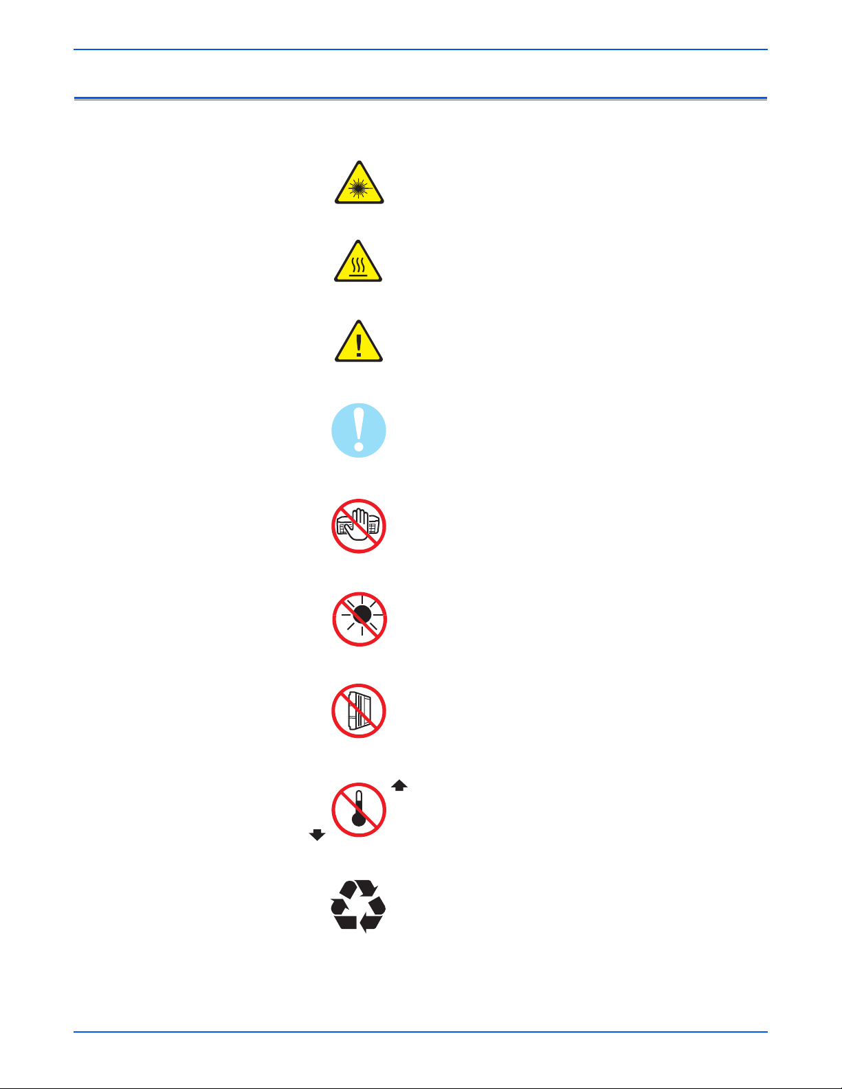
Symbols Marked on the Product
Warning. Danger invisible laser radiation when open. Avoid
direct exposure to beam.
Hot surface on or in the printer. Use caution to avoid
personal injury.
Warning. Use caution to avoid personal injury.
Use caution (or draws attention to a particular component).
Refer to the manual(s) for information.
0°C
32°F
Do not touch the OPC Drum.
Do not expose the item to sunlight.
Do not tilt the Print Cartridge.
35°C
Do not expose item to high temperature.
95°F
Recycle the item.
iv Phaser 3250 Laser Printer Service Manual
Page 6

Power Safety Precautions
Warning
Power Source
Disconnecting Power
For 115 VAC printers, do not apply more than 127 volts RMS between the
supply conductors or between either supply conductor and ground. For 230
VAC printers, do not apply more than 254 volts RMS between the supply
conductors or between either supply conductor and ground. Use only the
specified power cord and connector. This manual assumes that the reader is
a qualified service technician.
Plug the three-wire power cord (with grounding prong) into a grounded AC
outlet only. If necessary, contact a licensed electrician to install a properly
grounded outlet. If the product loses its ground connection, contact with
conductive parts may cause an electrical shock. A protective ground
connection by way of the grounding conductor in the power cord is essential
for safe operation.
Turning the power Off using the power switch does not completely deenergize the printer. You must also disconnect the power cord from the
printer’s Alternating Current (AC) inlet. Disconnect the power cord by pulling
the plug, not the cord.
Disconnect the power cord in the following cases:
■ if the power cord or plug is frayed or otherwise damaged,
■ if any liquid or foreign material is spilled into the product,
■ if the printer is exposed to any excess moisture,
■ if the printer is dropped or damaged,
■ if you suspect that the product needs servicing or repair,
■ whenever you clean the product.
Phaser 3250 Laser Printer Service Manual v
Page 7

Electrostatic Discharge Precautions
Some semiconductor components, and the respective sub-assemblies that
contain them, are vulnerable to damage by Electrostatic Discharge (ESD).
These components include Integrated Circuits (ICs), Large-Scale Integrated
circuits (LSIs), field-effect transistors, and other semiconductor chip
components. The following techniques will reduce the occurrence of
component damage caused by static electricity.
Be sure the power is Off to the chassis or circuit board, and observe all other
safety precautions.
■ Immediately before handling any semiconductor components assemblies,
drain the electrostatic charge from your body. This can be accomplished
by touching an earth ground source or by wearing a wrist strap device
connected to an earth ground source. Wearing a wrist strap will also
prevent accumulation of additional bodily static charges. Be sure to
remove the wrist strap before applying power to the unit under test to
avoid potential shock.
■ After removing a static sensitive assembly from its anti-static bag, place it
on a grounded conductive surface. If the anti-static bag is conductive, you
may ground the bag and use it as a conductive surface.
■ Do not use freon-propelled chemicals. These can generate electrical
charges sufficient to damage some devices.
■ Do not remove a replacement component or electrical sub-assembly from
its protective package until you are ready to install it.
■ Immediately before removing the protective material from the leads of a
replacement device, touch the protective material to the chassis or circuit
assembly into which the device will be installed.
■ Minimize body motions when handling unpacked replacement devices.
Motion such as your clothes brushing together, or lifting a foot from a
carpeted floor can generate enough static electricity to damage an
electro-statically sensitive device.
■ Handle IC’s and Erasable Programmable Read-Only Memories
(EPROM’s) carefully to avoid bending pins.
■ Pay attention to the direction of parts when mounting or inserting them on
Printed Circuit Boards (PCB’s).
vi Phaser 3250 Laser Printer Service Manual
Page 8

Service Safety Summary
General Guidelines
Warning Labels
For qualified service personnel only: Refer also to the preceding “Power Safety
Precautions” on page v.
Use care when servicing with power: Dangerous voltages may exist at several
points in this product. To avoid personal injury, do not touch exposed
connections and components while power is On. Disconnect power before
removing the power supply shield or replacing components.
Do not wear jewelry: Remove jewelry prior to servicing. Rings, necklaces, and
other metallic objects could come into contact with dangerous voltages and
currents.
Ozone: During normal operation, this machine produces ozone gas. The
amount of ozone produced does not present a hazard to the operator.
However, it is advisable that the machine be operated in a well ventilated
area.
Read and obey all posted warning labels. Throughout the printer, warning
labels are displayed on potentially dangerous components. As you service the
printer, check to make certain that all warning labels remain in place.
Safety Interlocks
Make sure all covers are in place and all Interlock Switches are functioning
correctly after you have completed a printer service call. If you bypass an
Interlock Switch during a service call, use extreme caution when working on
or around the printer.
Class 1 Laser Product
The Phaser 3250 is certified to comply with Laser Product Performance
Standards set by the U.S. Department of Health and Human Services as a
Class 1 Laser Product. This means that this product does not emit hazardous
laser radiation; which is possible only because the laser beam is totally
enclosed during all modes of customer operation. When servicing the printer
or laser unit, follow the procedures specified in this manual and there will be
no hazards from the laser.
Phaser 3250 Laser Printer Service Manual vii
Page 9

Maintenance
Warning
Cleaning
Toner Cartridge
Fuses
Before cleaning this product, unplug the product from the electrical outlet.
Aways use materials specifically designated for this product, the use of other
materials may result in poor performance and create a hazardous situation.
Do not use aerosol cleaners; they may be explosive and flammable under
certain conditions.
The product contains a dry image cartridge that is recyclable. Under various
state and local laws, it may be illegal to dispose of the cartridge into the
municipal waste. Check with the local waste officials for details on recycling
options or the proper disposal procedures.
Do not install a Fuse of a different type or rating. Installing the wrong type or
rating of Fuse can cause overheating and a risk of fire.
Part Replacement
Only use genuine Xerox approved spare parts or components to maintain
compliance with legislation and safety certification.
Reassembly Precautions
Use extreme care during assembly. Check all harnesses to ensure they do not
contact moving parts and do not get trapped between components.
viii Phaser 3250 Laser Printer Service Manual
Page 10

Servicing Electrical Components
Warning
Warning
Warning
Before starting any service procedure, switch the printer power Off and
unplug the power cord from the wall outlet. If you must service the printer with
power applied, be aware of the potential for electrical shock.
Do not touch any electrical component unless you are instructed to do so by a
service procedure.
Servicing Mechanical Components
When servicing mechanical components within the printer, manually rotate
the Drive Assemblies, Rollers, and Gears.
Do not try to manually rotate or manually stop the drive assemblies while any
printer motor is running.
Servicing Fuser Components
This printer uses heat to fuse the toner image to paper. The Fuser is VERY
HOT. Turn the printer power Off and wait at least 5 minutes for the Fuser to
cool before attempting to service the Fuser or adjacent components.
Phaser 3250 Laser Printer Service Manual ix
Page 11

Moving the Printer
Warning
Warning
Warning
11.9 kg
26.2 lb
s3250-001
Parts of the printer are hot. Wait at least 30 minutes for the printer to cool
before moving or packing the printer.
Use the power switch to turn Off the printer, and unplug all cables and cords.
Do not turn the printer Off by pulling the power cord or using a power-strip
with an On/Off switch.
Back injury could result if you do not lift the printer properly.
■ The printer can be lifted by one person. Use safety lifting and handling
techniques when moving the printer.
■ Always move the printer separately from Tray 2.
x Phaser 3250 Laser Printer Service Manual
Page 12

When shipping the printer, repack the printer using the original packing
Caution
material and boxes or a Xerox packaging kit. Instructions for repacking the
printer are included in the kit. If you do not have all the original packaging, or
are unable to repackage the printer, contact your local Xerox service
representative.
Failure to repackage the printer properly for shipment can result in damage to
the printer. Damage to the printer caused by improper packaging is not
covered by the Xerox warranty, service agreement, or Total Satisfaction
Guarantee.
Phaser 3250 Laser Printer Service Manual xi
Page 13

Regulatory Information
United States (FCC Regulations)
Xerox has tested this product to electromagnetic emission and immunity
standards. These standards are designed to mitigate interference caused or
received by this product in a typical office environment.
This equipment has been tested and found to comply with the limits for a
Class B digital device, pursuant to Part 15 of the Federal Communications
Commission (FCC) Rules. These limits are designed to provide reasonable
protection against harmful interference in a residential installation. This
equipment generates, uses, and can radiate radio frequency energy. If it is not
installed and used in accordance with these instructions, it may cause harmful
interference to radio communications. However, there is no guarantee that
interference will not occur in a particular installation. If this equipment does
cause harmful interference to radio or television reception, which can be
determined by turning the equipment Off and On, the user is encouraged to
try to correct the interference by one or more of the following measures:
■ Reorient or relocate the receiver (device being interfered with).
■ Increase the separation between the printer and the receiver.
■ Connect the equipment into an outlet on a circuit different from that which
■ Consult the dealer or an experienced radio/television technician for help.
Any changes or modifications not expressly approved by Xerox could void the
user's authority to operate the equipment. To ensure compliance with Part 15
of the FCC rules, use shielded interface cables.
Canada (Regulations)
This Class B digital apparatus complies with Canadian ICES-003.
Cet appareil numérique de la classe B est conforme à la norme NMB-003 du
Canada.
the receiver is connected.
xii Phaser 3250 Laser Printer Service Manual
Page 14

European Union
The CE mark applied to this product symbolizes Xerox’s
declaration of conformity with the following applicable
Directives of the European Union as of the dates indicated:
December 12, 2006: Council Directive 2006/95/EC as amended. Approximation of
the laws of the member states related to low voltage equipment.
December 15, 2004: Council Directive 2004/108/EC as amended. Approximation of
the laws of the member states related to electromagnetic compability.
This product, if used properly in accordance with the user's instructions, is
neither dangerous for the consumer nor for the environment.
To ensure compliance with European Union regulations, use shielded
interface cables.
A signed copy of the Declaration of Conformity for this product can be
obtained from Xerox.
Phaser 3250 Laser Printer Service Manual xiii
Page 15

Manual Organization
The Phaser 3250 Laser Printer Service Manual is the primary document used
for repairing, maintaining, and troubleshooting the printer. Use this manual as
your primary resource for understanding the operational characteristics of the
printer and all available options. This manual describes specifications, theory,
and the diagnosis and repair of problems occurring in the print engine and
attached options. Also included are detailed replacement procedures, parts
lists, and wiring diagrams.
The Phaser 3250 Laser Printer Service Manual contains these sections:
Introductory, Safety, and Regulatory Information: This section contains important
safety information and regulatory requirements.
Section 1 - General Information: This section contains an overview of the
printer’s operation, configuration, specifications, and consumables.
Section 2 - Theory of Operation: This section contains detailed functional
information on the print engine components.
Section 3 - Error Codes and Messages: This section provides detailed
troubleshooting procedures for error messages and codes generated by
resident diagnostics.
Section 4 - General Troubleshooting: This section contains the operation of
Power On Self Test (POST) and Service Diagnostics. In addition, this section
includes troubleshooting methods for situations where error indicator is not
available.
Section 5 - Print-Quality Troubleshooting: This section focuses on techniques to
correct image quality problems associated with the printer output.
Section 6 - Adjustments and Calibrations: This section provides procedures for
the adjustment of the print engine components.
Section 7 - Cleaning and Maintenance: This section provides periodic cleaning
procedures for the printer.
Section 8 - Service Parts Disassembly:
procedures for spare parts listed in the Parts List. A replacement procedure is
included when necessary.
Section 9 - Parts List: This section contains exploded views of the print engine
and optional Field Replaceable Units (FRUs), as well as part numbers for
orderable parts.
Section 10 - Plug/Jack and Wiring Diagrams: This section contains the plug/jack
locations and the wiring diagrams for the printer.
Appendix A - Reference: This section provides an illustration of the printer’s
Control Panel menu structure, printer firmware update instructions, and a list
of acronyms and abbreviations.
This section contains removal
xiv Phaser 3250 Laser Printer Service Manual
Page 16

Service Terms . . . . . . . . . . . . . . . . . . . . . . . . . . . . . . . . . . . . . . . . . . . . . . . . . . . . . . . . . . . . . . . . . . . . . . . . . . . . . . . . iii
Symbols Marked on the Product . . . . . . . . . . . . . . . . . . . . . . . . . . . . . . . . . . . . . . . . . . . . . . . . . . . . . . . . . . . . . . . . . . iv
Power Safety Precautions . . . . . . . . . . . . . . . . . . . . . . . . . . . . . . . . . . . . . . . . . . . . . . . . . . . . . . . . . . . . . . . . . . . . . . . .v
Electrostatic Discharge Precautions. . . . . . . . . . . . . . . . . . . . . . . . . . . . . . . . . . . . . . . . . . . . . . . . . . . . . . . . . . . . . . . . vi
Service Safety Summary . . . . . . . . . . . . . . . . . . . . . . . . . . . . . . . . . . . . . . . . . . . . . . . . . . . . . . . . . . . . . . . . . . . . . . . . vii
Regulatory Information . . . . . . . . . . . . . . . . . . . . . . . . . . . . . . . . . . . . . . . . . . . . . . . . . . . . . . . . . . . . . . . . . . . . . . . . .xii
Manual Organization . . . . . . . . . . . . . . . . . . . . . . . . . . . . . . . . . . . . . . . . . . . . . . . . . . . . . . . . . . . . . . . . . . . . . . . . . . xiv
1 General Information
Printer Introduction and Overview. . . . . . . . . . . . . . . . . . . . . . . . . . . . . . . . . . . . . . . . . . . . . . . . . . . . . . . . . . . . . . . . 1-2
Technical Support Information . . . . . . . . . . . . . . . . . . . . . . . . . . . . . . . . . . . . . . . . . . . . . . . . . . . . . . . . . . . 1-2
Printer Configurations . . . . . . . . . . . . . . . . . . . . . . . . . . . . . . . . . . . . . . . . . . . . . . . . . . . . . . . . . . . . . . . . . . . . . . . . . 1-3
Parts of the Printer. . . . . . . . . . . . . . . . . . . . . . . . . . . . . . . . . . . . . . . . . . . . . . . . . . . . . . . . . . . . . . . . . . . . . . . . . . . . 1-4
Front View . . . . . . . . . . . . . . . . . . . . . . . . . . . . . . . . . . . . . . . . . . . . . . . . . . . . . . . . . . . . . . . . . . . . . . . . . . . 1-4
Rear View . . . . . . . . . . . . . . . . . . . . . . . . . . . . . . . . . . . . . . . . . . . . . . . . . . . . . . . . . . . . . . . . . . . . . . . . . . . 1-4
Duplex Unit . . . . . . . . . . . . . . . . . . . . . . . . . . . . . . . . . . . . . . . . . . . . . . . . . . . . . . . . . . . . . . . . . . . . . . . . . . 1-5
LAN (Network Model) . . . . . . . . . . . . . . . . . . . . . . . . . . . . . . . . . . . . . . . . . . . . . . . . . . . . . . . . . . . . . . . . . . 1-5
Control Panel. . . . . . . . . . . . . . . . . . . . . . . . . . . . . . . . . . . . . . . . . . . . . . . . . . . . . . . . . . . . . . . . . . . . . . . . . 1-6
Printer Options. . . . . . . . . . . . . . . . . . . . . . . . . . . . . . . . . . . . . . . . . . . . . . . . . . . . . . . . . . . . . . . . . . . . . . . . . . . . . . . 1-8
Additional Memory . . . . . . . . . . . . . . . . . . . . . . . . . . . . . . . . . . . . . . . . . . . . . . . . . . . . . . . . . . . . . . . . . . . . 1-8
Optional 250-Sheet Feeder (Tray 2). . . . . . . . . . . . . . . . . . . . . . . . . . . . . . . . . . . . . . . . . . . . . . . . . . . . . . . . 1-8
Maintenance Items. . . . . . . . . . . . . . . . . . . . . . . . . . . . . . . . . . . . . . . . . . . . . . . . . . . . . . . . . . . . . . . . . . . . . . . . . . . . 1-9
Consumables. . . . . . . . . . . . . . . . . . . . . . . . . . . . . . . . . . . . . . . . . . . . . . . . . . . . . . . . . . . . . . . . . . . . . . . . . . . . . . . 1-10
Specifications . . . . . . . . . . . . . . . . . . . . . . . . . . . . . . . . . . . . . . . . . . . . . . . . . . . . . . . . . . . . . . . . . . . . . . . . . . . . . . 1-11
Functional Specifications. . . . . . . . . . . . . . . . . . . . . . . . . . . . . . . . . . . . . . . . . . . . . . . . . . . . . . . . . . . . . . . 1-11
Memory Specifications . . . . . . . . . . . . . . . . . . . . . . . . . . . . . . . . . . . . . . . . . . . . . . . . . . . . . . . . . . . . . . . . 1-11
Environmental Specifications . . . . . . . . . . . . . . . . . . . . . . . . . . . . . . . . . . . . . . . . . . . . . . . . . . . . . . . . . . . 1-12
Electrical Specifications. . . . . . . . . . . . . . . . . . . . . . . . . . . . . . . . . . . . . . . . . . . . . . . . . . . . . . . . . . . . . . . . 1-13
Print Speed . . . . . . . . . . . . . . . . . . . . . . . . . . . . . . . . . . . . . . . . . . . . . . . . . . . . . . . . . . . . . . . . . . . . . . . . . 1-13
Operating Mode. . . . . . . . . . . . . . . . . . . . . . . . . . . . . . . . . . . . . . . . . . . . . . . . . . . . . . . . . . . . . . . . . . . . . . 1-14
Warm-Up Time . . . . . . . . . . . . . . . . . . . . . . . . . . . . . . . . . . . . . . . . . . . . . . . . . . . . . . . . . . . . . . . . . . . . . . 1-14
First Print Output Time . . . . . . . . . . . . . . . . . . . . . . . . . . . . . . . . . . . . . . . . . . . . . . . . . . . . . . . . . . . . . . . . 1-14
Image Specifications . . . . . . . . . . . . . . . . . . . . . . . . . . . . . . . . . . . . . . . . . . . . . . . . . . . . . . . . . . . . . . . . . . 1-15
Physical Dimensions and Clearances . . . . . . . . . . . . . . . . . . . . . . . . . . . . . . . . . . . . . . . . . . . . . . . . . . . . . 1-16
Mounting Surface Specifications. . . . . . . . . . . . . . . . . . . . . . . . . . . . . . . . . . . . . . . . . . . . . . . . . . . . . . . . . 1-17
Media and Tray Specifications. . . . . . . . . . . . . . . . . . . . . . . . . . . . . . . . . . . . . . . . . . . . . . . . . . . . . . . . . . . 1-18
Non-Genuine Mode . . . . . . . . . . . . . . . . . . . . . . . . . . . . . . . . . . . . . . . . . . . . . . . . . . . . . . . . . . . . . . . . . . . . . . . . . . 1-20
Toner Remaining Amount . . . . . . . . . . . . . . . . . . . . . . . . . . . . . . . . . . . . . . . . . . . . . . . . . . . . . . . . . . . . . . 1-20
Maintenance Function . . . . . . . . . . . . . . . . . . . . . . . . . . . . . . . . . . . . . . . . . . . . . . . . . . . . . . . . . . . . . . . . . . . . . . . . 1-20
Firmware Update . . . . . . . . . . . . . . . . . . . . . . . . . . . . . . . . . . . . . . . . . . . . . . . . . . . . . . . . . . . . . . . . . . . . . 1-20
Diagnostics . . . . . . . . . . . . . . . . . . . . . . . . . . . . . . . . . . . . . . . . . . . . . . . . . . . . . . . . . . . . . . . . . . . . . . . . . . . . . . . . 1-21
Power Save Mode . . . . . . . . . . . . . . . . . . . . . . . . . . . . . . . . . . . . . . . . . . . . . . . . . . . . . . . . . . . . . . . . . . . . . . . . . . . 1-21
Printer Settings Utility . . . . . . . . . . . . . . . . . . . . . . . . . . . . . . . . . . . . . . . . . . . . . . . . . . . . . . . . . . . . . . . . . . . . . . . . 1-23
Accessing Printer Settings Utility . . . . . . . . . . . . . . . . . . . . . . . . . . . . . . . . . . . . . . . . . . . . . . . . . . . . . . . . 1-23
CentreWare IS . . . . . . . . . . . . . . . . . . . . . . . . . . . . . . . . . . . . . . . . . . . . . . . . . . . . . . . . . . . . . . . . . . . . . . . . . . . . . . 1-24
Accessing the CentreWare IS . . . . . . . . . . . . . . . . . . . . . . . . . . . . . . . . . . . . . . . . . . . . . . . . . . . . . . . . . . . 1-24
Contents
Contents
Phaser 3250 Laser Printer Service Manual xv
Page 17

Reports and Information Pages . . . . . . . . . . . . . . . . . . . . . . . . . . . . . . . . . . . . . . . . . . . . . . . . . . . . . . . . . . . . . . . . . 1-26
Control Panel Method . . . . . . . . . . . . . . . . . . . . . . . . . . . . . . . . . . . . . . . . . . . . . . . . . . . . . . . . . . . . . . . . . 1-27
CentreWare IS Method (Network) . . . . . . . . . . . . . . . . . . . . . . . . . . . . . . . . . . . . . . . . . . . . . . . . . . . . . . . . 1-28
Printer Settings Utility Method (USB Connection). . . . . . . . . . . . . . . . . . . . . . . . . . . . . . . . . . . . . . . . . . . . 1-31
Demo Page . . . . . . . . . . . . . . . . . . . . . . . . . . . . . . . . . . . . . . . . . . . . . . . . . . . . . . . . . . . . . . . . . . . . . . . . . 1-32
Menu Map . . . . . . . . . . . . . . . . . . . . . . . . . . . . . . . . . . . . . . . . . . . . . . . . . . . . . . . . . . . . . . . . . . . . . . . . . . 1-33
Configuration Page . . . . . . . . . . . . . . . . . . . . . . . . . . . . . . . . . . . . . . . . . . . . . . . . . . . . . . . . . . . . . . . . . . . 1-34
Event Log . . . . . . . . . . . . . . . . . . . . . . . . . . . . . . . . . . . . . . . . . . . . . . . . . . . . . . . . . . . . . . . . . . . . . . . . . . 1-36
Supplies Info . . . . . . . . . . . . . . . . . . . . . . . . . . . . . . . . . . . . . . . . . . . . . . . . . . . . . . . . . . . . . . . . . . . . . . . . 1-37
Page Count . . . . . . . . . . . . . . . . . . . . . . . . . . . . . . . . . . . . . . . . . . . . . . . . . . . . . . . . . . . . . . . . . . . . . . . . . 1-37
Print Cleaning Page. . . . . . . . . . . . . . . . . . . . . . . . . . . . . . . . . . . . . . . . . . . . . . . . . . . . . . . . . . . . . . . . . . . 1-38
PCL Font List. . . . . . . . . . . . . . . . . . . . . . . . . . . . . . . . . . . . . . . . . . . . . . . . . . . . . . . . . . . . . . . . . . . . . . . . 1-39
PS Font List. . . . . . . . . . . . . . . . . . . . . . . . . . . . . . . . . . . . . . . . . . . . . . . . . . . . . . . . . . . . . . . . . . . . . . . . . 1-39
2 Theory of Operation
Phaser 3250 Operational Overview . . . . . . . . . . . . . . . . . . . . . . . . . . . . . . . . . . . . . . . . . . . . . . . . . . . . . . . . . . . . . . . 2-2
System Overview. . . . . . . . . . . . . . . . . . . . . . . . . . . . . . . . . . . . . . . . . . . . . . . . . . . . . . . . . . . . . . . . . . . . . . 2-2
Paper Path of the Printer . . . . . . . . . . . . . . . . . . . . . . . . . . . . . . . . . . . . . . . . . . . . . . . . . . . . . . . . . . . . . . . . . . . . . . . 2-3
Paper Feeding . . . . . . . . . . . . . . . . . . . . . . . . . . . . . . . . . . . . . . . . . . . . . . . . . . . . . . . . . . . . . . . . . . . . . . . . 2-3
Major Assemblies and Functions. . . . . . . . . . . . . . . . . . . . . . . . . . . . . . . . . . . . . . . . . . . . . . . . . . . . . . . . . . . . . . . . . 2-8
Transfer Roller. . . . . . . . . . . . . . . . . . . . . . . . . . . . . . . . . . . . . . . . . . . . . . . . . . . . . . . . . . . . . . . . . . . . . . . . 2-8
Drive Assembly . . . . . . . . . . . . . . . . . . . . . . . . . . . . . . . . . . . . . . . . . . . . . . . . . . . . . . . . . . . . . . . . . . . . . . . 2-8
Fuser . . . . . . . . . . . . . . . . . . . . . . . . . . . . . . . . . . . . . . . . . . . . . . . . . . . . . . . . . . . . . . . . . . . . . . . . . . . . . . . 2-9
Laser Unit . . . . . . . . . . . . . . . . . . . . . . . . . . . . . . . . . . . . . . . . . . . . . . . . . . . . . . . . . . . . . . . . . . . . . . . . . . 2-11
Print Cartridge. . . . . . . . . . . . . . . . . . . . . . . . . . . . . . . . . . . . . . . . . . . . . . . . . . . . . . . . . . . . . . . . . . . . . . . 2-12
Electrical Components . . . . . . . . . . . . . . . . . . . . . . . . . . . . . . . . . . . . . . . . . . . . . . . . . . . . . . . . . . . . . . . . . . . . . . . . 2-13
Main Controller Board . . . . . . . . . . . . . . . . . . . . . . . . . . . . . . . . . . . . . . . . . . . . . . . . . . . . . . . . . . . . . . . . . 2-13
High-Voltage Power Supply (HVPS) . . . . . . . . . . . . . . . . . . . . . . . . . . . . . . . . . . . . . . . . . . . . . . . . . . . . . . 2-18
Low-Voltage Power Supply (LVPS) (SMPS) . . . . . . . . . . . . . . . . . . . . . . . . . . . . . . . . . . . . . . . . . . . . . . . . 2-21
Fuser AC Power Control . . . . . . . . . . . . . . . . . . . . . . . . . . . . . . . . . . . . . . . . . . . . . . . . . . . . . . . . . . . . . . . 2-23
Engine F/W . . . . . . . . . . . . . . . . . . . . . . . . . . . . . . . . . . . . . . . . . . . . . . . . . . . . . . . . . . . . . . . . . . . . . . . . . 2-24
3 Error Messages and Codes
Introduction. . . . . . . . . . . . . . . . . . . . . . . . . . . . . . . . . . . . . . . . . . . . . . . . . . . . . . . . . . . . . . . . . . . . . . . . . . . . . . . . . 3-2
Accessing the Event Log . . . . . . . . . . . . . . . . . . . . . . . . . . . . . . . . . . . . . . . . . . . . . . . . . . . . . . . . . . . . . . . . 3-2
Event Log . . . . . . . . . . . . . . . . . . . . . . . . . . . . . . . . . . . . . . . . . . . . . . . . . . . . . . . . . . . . . . . . . . . . . . . . . . . 3-3
Servicing Instructions . . . . . . . . . . . . . . . . . . . . . . . . . . . . . . . . . . . . . . . . . . . . . . . . . . . . . . . . . . . . . . . . . . . . . . . . . 3-4
Error Messages and Procedures . . . . . . . . . . . . . . . . . . . . . . . . . . . . . . . . . . . . . . . . . . . . . . . . . . . . . . . . . . . . . . . . . 3-5
Error Message Abbreviations. . . . . . . . . . . . . . . . . . . . . . . . . . . . . . . . . . . . . . . . . . . . . . . . . . . . . . . . . . . . . 3-5
Error Message Summary. . . . . . . . . . . . . . . . . . . . . . . . . . . . . . . . . . . . . . . . . . . . . . . . . . . . . . . . . . . . . . . . 3-6
Jam Errors. . . . . . . . . . . . . . . . . . . . . . . . . . . . . . . . . . . . . . . . . . . . . . . . . . . . . . . . . . . . . . . . . . . . . . . . . . . . . . . . . . 3-7
Paper Jam 0 . . . . . . . . . . . . . . . . . . . . . . . . . . . . . . . . . . . . . . . . . . . . . . . . . . . . . . . . . . . . . . . . . . . . . . . . . 3-7
Paper Jam 1 . . . . . . . . . . . . . . . . . . . . . . . . . . . . . . . . . . . . . . . . . . . . . . . . . . . . . . . . . . . . . . . . . . . . . . . . . 3-9
Paper Jam 2 . . . . . . . . . . . . . . . . . . . . . . . . . . . . . . . . . . . . . . . . . . . . . . . . . . . . . . . . . . . . . . . . . . . . . . . . 3-11
Jam Duplex . . . . . . . . . . . . . . . . . . . . . . . . . . . . . . . . . . . . . . . . . . . . . . . . . . . . . . . . . . . . . . . . . . . . . . . . . 3-13
Tray and Paper Errors . . . . . . . . . . . . . . . . . . . . . . . . . . . . . . . . . . . . . . . . . . . . . . . . . . . . . . . . . . . . . . . . . . . . . . . . 3-14
No Paper Error. . . . . . . . . . . . . . . . . . . . . . . . . . . . . . . . . . . . . . . . . . . . . . . . . . . . . . . . . . . . . . . . . . . . . . . 3-14
Paper Empty without Indication. . . . . . . . . . . . . . . . . . . . . . . . . . . . . . . . . . . . . . . . . . . . . . . . . . . . . . . . . . 3-15
Multi Feeding. . . . . . . . . . . . . . . . . . . . . . . . . . . . . . . . . . . . . . . . . . . . . . . . . . . . . . . . . . . . . . . . . . . . . . . . 3-16
Wrong Print Position. . . . . . . . . . . . . . . . . . . . . . . . . . . . . . . . . . . . . . . . . . . . . . . . . . . . . . . . . . . . . . . . . . 3-17
xvi Phaser 3250 Laser Printer Service Manual
Page 18

Consumables/Routine Maintenance Part Errors. . . . . . . . . . . . . . . . . . . . . . . . . . . . . . . . . . . . . . . . . . . . . . . . . . . . . 3-18
Fuser Error . . . . . . . . . . . . . . . . . . . . . . . . . . . . . . . . . . . . . . . . . . . . . . . . . . . . . . . . . . . . . . . . . . . . . . . . . 3-18
Paper Rolled in the Fuser. . . . . . . . . . . . . . . . . . . . . . . . . . . . . . . . . . . . . . . . . . . . . . . . . . . . . . . . . . . . . . . 3-20
Fuser Gear Does Not Function due to Overheating . . . . . . . . . . . . . . . . . . . . . . . . . . . . . . . . . . . . . . . . . . . 3-22
Paper Rolled on the OPC Drum . . . . . . . . . . . . . . . . . . . . . . . . . . . . . . . . . . . . . . . . . . . . . . . . . . . . . . . . . . 3-24
Print Cartridge Not Installed . . . . . . . . . . . . . . . . . . . . . . . . . . . . . . . . . . . . . . . . . . . . . . . . . . . . . . . . . . . . 3-26
Motor, Cover, and Laser Errors . . . . . . . . . . . . . . . . . . . . . . . . . . . . . . . . . . . . . . . . . . . . . . . . . . . . . . . . . . . . . . . . . 3-27
Defective Motor Operation. . . . . . . . . . . . . . . . . . . . . . . . . . . . . . . . . . . . . . . . . . . . . . . . . . . . . . . . . . . . . . 3-27
Front Cover Open. . . . . . . . . . . . . . . . . . . . . . . . . . . . . . . . . . . . . . . . . . . . . . . . . . . . . . . . . . . . . . . . . . . . . 3-28
Laser Unit Not Ready. . . . . . . . . . . . . . . . . . . . . . . . . . . . . . . . . . . . . . . . . . . . . . . . . . . . . . . . . . . . . . . . . . 3-29
Print-Quality Error . . . . . . . . . . . . . . . . . . . . . . . . . . . . . . . . . . . . . . . . . . . . . . . . . . . . . . . . . . . . . . . . . . . . . . . . . . . 3-30
Vertical Line Getting Curved . . . . . . . . . . . . . . . . . . . . . . . . . . . . . . . . . . . . . . . . . . . . . . . . . . . . . . . . . . . . 3-30
4 General Troubleshooting
Introduction. . . . . . . . . . . . . . . . . . . . . . . . . . . . . . . . . . . . . . . . . . . . . . . . . . . . . . . . . . . . . . . . . . . . . . . . . . . . . . . . . 4-2
Service Diagnostics. . . . . . . . . . . . . . . . . . . . . . . . . . . . . . . . . . . . . . . . . . . . . . . . . . . . . . . . . . . . . . . . . . . . 4-2
LED Status and Errors . . . . . . . . . . . . . . . . . . . . . . . . . . . . . . . . . . . . . . . . . . . . . . . . . . . . . . . . . . . . . . . . . . . . . . . . . 4-2
No Error LED when the Front Cover is Open . . . . . . . . . . . . . . . . . . . . . . . . . . . . . . . . . . . . . . . . . . . . . . . . . 4-4
Inoperable Printer Troubleshooting . . . . . . . . . . . . . . . . . . . . . . . . . . . . . . . . . . . . . . . . . . . . . . . . . . . . . . . . . . . . . . . 4-5
The Printer is Not Responding to the Print Command. . . . . . . . . . . . . . . . . . . . . . . . . . . . . . . . . . . . . . . . . . 4-5
The Printer is Not Responding to a Print Command due to Incorrect Setup . . . . . . . . . . . . . . . . . . . . . . . . . 4-6
SPOOL Error . . . . . . . . . . . . . . . . . . . . . . . . . . . . . . . . . . . . . . . . . . . . . . . . . . . . . . . . . . . . . . . . . . . . . . . . . 4-7
Power Supply Troubleshooting . . . . . . . . . . . . . . . . . . . . . . . . . . . . . . . . . . . . . . . . . . . . . . . . . . . . . . . . . . . . . . . . . . 4-8
AC Power Troubleshooting . . . . . . . . . . . . . . . . . . . . . . . . . . . . . . . . . . . . . . . . . . . . . . . . . . . . . . . . . . . . . . 4-8
No Power. . . . . . . . . . . . . . . . . . . . . . . . . . . . . . . . . . . . . . . . . . . . . . . . . . . . . . . . . . . . . . . . . . . . . . . . . . . . 4-9
Print Cartridge Troubleshooting. . . . . . . . . . . . . . . . . . . . . . . . . . . . . . . . . . . . . . . . . . . . . . . . . . . . . . . . . . . . . . . . . 4-11
Precautions for Print Cartridge . . . . . . . . . . . . . . . . . . . . . . . . . . . . . . . . . . . . . . . . . . . . . . . . . . . . . . . . . . 4-11
Print Cartridge Life . . . . . . . . . . . . . . . . . . . . . . . . . . . . . . . . . . . . . . . . . . . . . . . . . . . . . . . . . . . . . . . . . . . 4-11
Redistributing Toner . . . . . . . . . . . . . . . . . . . . . . . . . . . . . . . . . . . . . . . . . . . . . . . . . . . . . . . . . . . . . . . . . . 4-11
Operating System and Application Problems. . . . . . . . . . . . . . . . . . . . . . . . . . . . . . . . . . . . . . . . . . . . . . . . . . . . . . . 4-12
Common Windows Problems . . . . . . . . . . . . . . . . . . . . . . . . . . . . . . . . . . . . . . . . . . . . . . . . . . . . . . . . . . . 4-12
Common Macintosh Problems . . . . . . . . . . . . . . . . . . . . . . . . . . . . . . . . . . . . . . . . . . . . . . . . . . . . . . . . . . 4-12
Common Linux Problems . . . . . . . . . . . . . . . . . . . . . . . . . . . . . . . . . . . . . . . . . . . . . . . . . . . . . . . . . . . . . . 4-13
Common PostScript Problems . . . . . . . . . . . . . . . . . . . . . . . . . . . . . . . . . . . . . . . . . . . . . . . . . . . . . . . . . . 4-14
Contents
5 Print-Quality Troubleshooting
Print-Quality Problems Overview. . . . . . . . . . . . . . . . . . . . . . . . . . . . . . . . . . . . . . . . . . . . . . . . . . . . . . . . . . . . . . . . . 5-2
Defects Associated with Specific Printer Components . . . . . . . . . . . . . . . . . . . . . . . . . . . . . . . . . . . . . . . . . 5-2
Checklist Before Troubleshooting Print-Quality . . . . . . . . . . . . . . . . . . . . . . . . . . . . . . . . . . . . . . . . . . . . . . . . . . . . . . 5-4
Checking the Printer Condition . . . . . . . . . . . . . . . . . . . . . . . . . . . . . . . . . . . . . . . . . . . . . . . . . . . . . . . . . . . 5-4
Checklist Before Troubleshooting Image Quality. . . . . . . . . . . . . . . . . . . . . . . . . . . . . . . . . . . . . . . . . . . . . . 5-5
Test Print . . . . . . . . . . . . . . . . . . . . . . . . . . . . . . . . . . . . . . . . . . . . . . . . . . . . . . . . . . . . . . . . . . . . . . . . . . . . . . . . . . 5-10
Print-Quality Specifications . . . . . . . . . . . . . . . . . . . . . . . . . . . . . . . . . . . . . . . . . . . . . . . . . . . . . . . . . . . . . . . . . . . . 5-11
Environmental Condition. . . . . . . . . . . . . . . . . . . . . . . . . . . . . . . . . . . . . . . . . . . . . . . . . . . . . . . . . . . . . . . 5-11
Quality Paper. . . . . . . . . . . . . . . . . . . . . . . . . . . . . . . . . . . . . . . . . . . . . . . . . . . . . . . . . . . . . . . . . . . . . . . . 5-11
Paper Condition. . . . . . . . . . . . . . . . . . . . . . . . . . . . . . . . . . . . . . . . . . . . . . . . . . . . . . . . . . . . . . . . . . . . . . 5-11
Printer Condition . . . . . . . . . . . . . . . . . . . . . . . . . . . . . . . . . . . . . . . . . . . . . . . . . . . . . . . . . . . . . . . . . . . . . 5-11
Print-Quality Troubleshooting . . . . . . . . . . . . . . . . . . . . . . . . . . . . . . . . . . . . . . . . . . . . . . . . . . . . . . . . . . . . . . . . . . 5-12
Print-Quality Defect Definitions . . . . . . . . . . . . . . . . . . . . . . . . . . . . . . . . . . . . . . . . . . . . . . . . . . . . . . . . . . 5-12
Repeating Defect Measurement. . . . . . . . . . . . . . . . . . . . . . . . . . . . . . . . . . . . . . . . . . . . . . . . . . . . . . . . . . 5-13
Light or Undertone Print . . . . . . . . . . . . . . . . . . . . . . . . . . . . . . . . . . . . . . . . . . . . . . . . . . . . . . . . . . . . . . . 5-14
Black Print. . . . . . . . . . . . . . . . . . . . . . . . . . . . . . . . . . . . . . . . . . . . . . . . . . . . . . . . . . . . . . . . . . . . . . . . . . 5-16
Uneven Density . . . . . . . . . . . . . . . . . . . . . . . . . . . . . . . . . . . . . . . . . . . . . . . . . . . . . . . . . . . . . . . . . . . . . . 5-18
Background Contamination . . . . . . . . . . . . . . . . . . . . . . . . . . . . . . . . . . . . . . . . . . . . . . . . . . . . . . . . . . . . . 5-19
Phaser 3250 Laser Printer Service Manual xvii
Page 19

Ghosting (1) . . . . . . . . . . . . . . . . . . . . . . . . . . . . . . . . . . . . . . . . . . . . . . . . . . . . . . . . . . . . . . . . . . . . . . . . 5-21
Ghosting (2) . . . . . . . . . . . . . . . . . . . . . . . . . . . . . . . . . . . . . . . . . . . . . . . . . . . . . . . . . . . . . . . . . . . . . . . . 5-23
Ghosting (3) . . . . . . . . . . . . . . . . . . . . . . . . . . . . . . . . . . . . . . . . . . . . . . . . . . . . . . . . . . . . . . . . . . . . . . . . 5-24
Vertical White Line. . . . . . . . . . . . . . . . . . . . . . . . . . . . . . . . . . . . . . . . . . . . . . . . . . . . . . . . . . . . . . . . . . . . 5-25
Vertical Black Line and Band . . . . . . . . . . . . . . . . . . . . . . . . . . . . . . . . . . . . . . . . . . . . . . . . . . . . . . . . . . . . 5-27
Horizontal Black Line and Band. . . . . . . . . . . . . . . . . . . . . . . . . . . . . . . . . . . . . . . . . . . . . . . . . . . . . . . . . . 5-28
Black/White Spot. . . . . . . . . . . . . . . . . . . . . . . . . . . . . . . . . . . . . . . . . . . . . . . . . . . . . . . . . . . . . . . . . . . . . 5-29
Stains on the Front of the Page . . . . . . . . . . . . . . . . . . . . . . . . . . . . . . . . . . . . . . . . . . . . . . . . . . . . . . . . . . 5-31
Stains on the Back of the Page . . . . . . . . . . . . . . . . . . . . . . . . . . . . . . . . . . . . . . . . . . . . . . . . . . . . . . . . . . 5-32
Blank Page (1). . . . . . . . . . . . . . . . . . . . . . . . . . . . . . . . . . . . . . . . . . . . . . . . . . . . . . . . . . . . . . . . . . . . . . . 5-33
Blank Page (2). . . . . . . . . . . . . . . . . . . . . . . . . . . . . . . . . . . . . . . . . . . . . . . . . . . . . . . . . . . . . . . . . . . . . . . 5-34
6 Adjustments and Calibrations
Adjustments. . . . . . . . . . . . . . . . . . . . . . . . . . . . . . . . . . . . . . . . . . . . . . . . . . . . . . . . . . . . . . . . . . . . . . . . . . . . . . . . . 6-2
Altitude Adjustment. . . . . . . . . . . . . . . . . . . . . . . . . . . . . . . . . . . . . . . . . . . . . . . . . . . . . . . . . . . . . . . . . . . . 6-2
Adjusting Altitude . . . . . . . . . . . . . . . . . . . . . . . . . . . . . . . . . . . . . . . . . . . . . . . . . . . . . . . . . . . . . . . . . . . . . 6-3
7 Cleaning and Maintenance
Service Maintenance Procedure. . . . . . . . . . . . . . . . . . . . . . . . . . . . . . . . . . . . . . . . . . . . . . . . . . . . . . . . . . . . . . . . . . 7-2
Recommended Tools. . . . . . . . . . . . . . . . . . . . . . . . . . . . . . . . . . . . . . . . . . . . . . . . . . . . . . . . . . . . . . . . . . . 7-2
Cleaning. . . . . . . . . . . . . . . . . . . . . . . . . . . . . . . . . . . . . . . . . . . . . . . . . . . . . . . . . . . . . . . . . . . . . . . . . . . . . . . . . . . . 7-2
Cleaning the Print Cartridge. . . . . . . . . . . . . . . . . . . . . . . . . . . . . . . . . . . . . . . . . . . . . . . . . . . . . . . . . . . . . . 7-3
Cleaning the Laser Unit . . . . . . . . . . . . . . . . . . . . . . . . . . . . . . . . . . . . . . . . . . . . . . . . . . . . . . . . . . . . . . . . . 7-4
Printing the Print Cleaning Page . . . . . . . . . . . . . . . . . . . . . . . . . . . . . . . . . . . . . . . . . . . . . . . . . . . . . . . . . . 7-5
Maintenance . . . . . . . . . . . . . . . . . . . . . . . . . . . . . . . . . . . . . . . . . . . . . . . . . . . . . . . . . . . . . . . . . . . . . . . . . . . . . . . . 7-8
RIP (Repair, Inspect, and Prevent) Procedure. . . . . . . . . . . . . . . . . . . . . . . . . . . . . . . . . . . . . . . . . . . . . . . . 7-8
8 Service Parts Disassembly
Overview . . . . . . . . . . . . . . . . . . . . . . . . . . . . . . . . . . . . . . . . . . . . . . . . . . . . . . . . . . . . . . . . . . . . . . . . . . . . . . . . . . . 8-2
Standard Orientation of the Printer . . . . . . . . . . . . . . . . . . . . . . . . . . . . . . . . . . . . . . . . . . . . . . . . . . . . . . . . 8-3
Preparation . . . . . . . . . . . . . . . . . . . . . . . . . . . . . . . . . . . . . . . . . . . . . . . . . . . . . . . . . . . . . . . . . . . . . . . . . . 8-4
Notations in the Disassembly Text. . . . . . . . . . . . . . . . . . . . . . . . . . . . . . . . . . . . . . . . . . . . . . . . . . . . . . . . . 8-5
Fastener Types . . . . . . . . . . . . . . . . . . . . . . . . . . . . . . . . . . . . . . . . . . . . . . . . . . . . . . . . . . . . . . . . . . . . . . . 8-6
Maintenance Items and Consumables . . . . . . . . . . . . . . . . . . . . . . . . . . . . . . . . . . . . . . . . . . . . . . . . . . . . . . . . . . . . . 8-7
Print Cartridge (PL1.1.20). . . . . . . . . . . . . . . . . . . . . . . . . . . . . . . . . . . . . . . . . . . . . . . . . . . . . . . . . . . . . . . 8-7
Tray Holder Pad (PL11.1.14). . . . . . . . . . . . . . . . . . . . . . . . . . . . . . . . . . . . . . . . . . . . . . . . . . . . . . . . . . . . . 8-8
Transfer Roller (PL1.1.11). . . . . . . . . . . . . . . . . . . . . . . . . . . . . . . . . . . . . . . . . . . . . . . . . . . . . . . . . . . . . . 8-10
MEA Pick Up Unit (Pick-Up Roller) (PL6.1.26) . . . . . . . . . . . . . . . . . . . . . . . . . . . . . . . . . . . . . . . . . . . . . . 8-11
Fuser (PL9.1.0) . . . . . . . . . . . . . . . . . . . . . . . . . . . . . . . . . . . . . . . . . . . . . . . . . . . . . . . . . . . . . . . . . . . . . . 8-13
Thermistor Assembly (PL9.1.5). . . . . . . . . . . . . . . . . . . . . . . . . . . . . . . . . . . . . . . . . . . . . . . . . . . . . . . . . . 8-15
Thermostat (PL9.1.7) . . . . . . . . . . . . . . . . . . . . . . . . . . . . . . . . . . . . . . . . . . . . . . . . . . . . . . . . . . . . . . . . . 8-16
Heat Roller (PL9.1.10). . . . . . . . . . . . . . . . . . . . . . . . . . . . . . . . . . . . . . . . . . . . . . . . . . . . . . . . . . . . . . . . . 8-17
Pressure Roller (#1) (PL9.1.21) . . . . . . . . . . . . . . . . . . . . . . . . . . . . . . . . . . . . . . . . . . . . . . . . . . . . . . . . . 8-20
Pressure Roller (#2) (PL9.1.23) . . . . . . . . . . . . . . . . . . . . . . . . . . . . . . . . . . . . . . . . . . . . . . . . . . . . . . . . . 8-22
Halogen Lamp (PL9.1.30) . . . . . . . . . . . . . . . . . . . . . . . . . . . . . . . . . . . . . . . . . . . . . . . . . . . . . . . . . . . . . . 8-24
Covers . . . . . . . . . . . . . . . . . . . . . . . . . . . . . . . . . . . . . . . . . . . . . . . . . . . . . . . . . . . . . . . . . . . . . . . . . . . . . . . . . . . . 8-27
Front Cover (PL4.1.0) . . . . . . . . . . . . . . . . . . . . . . . . . . . . . . . . . . . . . . . . . . . . . . . . . . . . . . . . . . . . . . . . . 8-27
Rear Cover (PL5.1.0). . . . . . . . . . . . . . . . . . . . . . . . . . . . . . . . . . . . . . . . . . . . . . . . . . . . . . . . . . . . . . . . . . 8-28
Top Cover (PL2.1.0) . . . . . . . . . . . . . . . . . . . . . . . . . . . . . . . . . . . . . . . . . . . . . . . . . . . . . . . . . . . . . . . . . . 8-29
Left Cover (PL3.1.2) . . . . . . . . . . . . . . . . . . . . . . . . . . . . . . . . . . . . . . . . . . . . . . . . . . . . . . . . . . . . . . . . . . 8-32
Right Cover (PL3.1.3) . . . . . . . . . . . . . . . . . . . . . . . . . . . . . . . . . . . . . . . . . . . . . . . . . . . . . . . . . . . . . . . . . 8-34
Manual Feeder Cover (PL4.1.3). . . . . . . . . . . . . . . . . . . . . . . . . . . . . . . . . . . . . . . . . . . . . . . . . . . . . . . . . . 8-36
xviii Phaser 3250 Laser Printer Service Manual
Page 20

Contents
Duplex . . . . . . . . . . . . . . . . . . . . . . . . . . . . . . . . . . . . . . . . . . . . . . . . . . . . . . . . . . . . . . . . . . . . . . . . . . . . . . . . . . . . 8-37
Duplex Unit (PL1.1.13) . . . . . . . . . . . . . . . . . . . . . . . . . . . . . . . . . . . . . . . . . . . . . . . . . . . . . . . . . . . . . . . . 8-37
Paper Feeder . . . . . . . . . . . . . . . . . . . . . . . . . . . . . . . . . . . . . . . . . . . . . . . . . . . . . . . . . . . . . . . . . . . . . . . . . . . . . . . 8-38
Registration Clutch (PL6.1.18) . . . . . . . . . . . . . . . . . . . . . . . . . . . . . . . . . . . . . . . . . . . . . . . . . . . . . . . . . . 8-38
Pick-Up Solenoid (PL6.1.37). . . . . . . . . . . . . . . . . . . . . . . . . . . . . . . . . . . . . . . . . . . . . . . . . . . . . . . . . . . . 8-39
Feed Roller (Registration Roller) (PL6.1.20) . . . . . . . . . . . . . . . . . . . . . . . . . . . . . . . . . . . . . . . . . . . . . . . . 8-40
Feed Roller (PL6.1.83). . . . . . . . . . . . . . . . . . . . . . . . . . . . . . . . . . . . . . . . . . . . . . . . . . . . . . . . . . . . . . . . . 8-43
Feed Actuator (PL6.1.72). . . . . . . . . . . . . . . . . . . . . . . . . . . . . . . . . . . . . . . . . . . . . . . . . . . . . . . . . . . . . . . 8-45
Duplex Actuator (PL6.1.73). . . . . . . . . . . . . . . . . . . . . . . . . . . . . . . . . . . . . . . . . . . . . . . . . . . . . . . . . . . . . 8-47
Feed Sensor (Photo Interrupter) (PL6.1.75) . . . . . . . . . . . . . . . . . . . . . . . . . . . . . . . . . . . . . . . . . . . . . . . . 8-49
Empty Sensor (Photo Interrupter) (PL6.1.75). . . . . . . . . . . . . . . . . . . . . . . . . . . . . . . . . . . . . . . . . . . . . . . 8-51
Empty Actuator (PL6.1.84) . . . . . . . . . . . . . . . . . . . . . . . . . . . . . . . . . . . . . . . . . . . . . . . . . . . . . . . . . . . . . 8-53
Exit Actuator (PL9.1.19) . . . . . . . . . . . . . . . . . . . . . . . . . . . . . . . . . . . . . . . . . . . . . . . . . . . . . . . . . . . . . . . 8-54
Exit Sensor (Photo Interrupter) (PL9.1.37) . . . . . . . . . . . . . . . . . . . . . . . . . . . . . . . . . . . . . . . . . . . . . . . . . 8-55
Xerographics . . . . . . . . . . . . . . . . . . . . . . . . . . . . . . . . . . . . . . . . . . . . . . . . . . . . . . . . . . . . . . . . . . . . . . . . . . . . . . . 8-57
Laser Unit (PL1.1.12) . . . . . . . . . . . . . . . . . . . . . . . . . . . . . . . . . . . . . . . . . . . . . . . . . . . . . . . . . . . . . . . . . 8-57
CRUM Board (PL6.1.53) . . . . . . . . . . . . . . . . . . . . . . . . . . . . . . . . . . . . . . . . . . . . . . . . . . . . . . . . . . . . . . . 8-58
Exit Guide. . . . . . . . . . . . . . . . . . . . . . . . . . . . . . . . . . . . . . . . . . . . . . . . . . . . . . . . . . . . . . . . . . . . . . . . . . . . . . . . . . 8-59
Rear Guide Assembly (PL6.1.114) . . . . . . . . . . . . . . . . . . . . . . . . . . . . . . . . . . . . . . . . . . . . . . . . . . . . . . . 8-59
Drive . . . . . . . . . . . . . . . . . . . . . . . . . . . . . . . . . . . . . . . . . . . . . . . . . . . . . . . . . . . . . . . . . . . . . . . . . . . . . . . . . . . . . 8-60
Drive Assembly (PL1.1.8) . . . . . . . . . . . . . . . . . . . . . . . . . . . . . . . . . . . . . . . . . . . . . . . . . . . . . . . . . . . . . . 8-60
Electrical . . . . . . . . . . . . . . . . . . . . . . . . . . . . . . . . . . . . . . . . . . . . . . . . . . . . . . . . . . . . . . . . . . . . . . . . . . . . . . . . . . 8-62
Main Controller Board (PL1.1.2) . . . . . . . . . . . . . . . . . . . . . . . . . . . . . . . . . . . . . . . . . . . . . . . . . . . . . . . . . 8-62
Controller Shield (PL1.1.1) . . . . . . . . . . . . . . . . . . . . . . . . . . . . . . . . . . . . . . . . . . . . . . . . . . . . . . . . . . . . . 8-63
High Voltage Power Supply (HVPS) (PL1.1.3) . . . . . . . . . . . . . . . . . . . . . . . . . . . . . . . . . . . . . . . . . . . . . . 8-64
Low Voltage Power Supply (LVPS) (PL1.1.4) . . . . . . . . . . . . . . . . . . . . . . . . . . . . . . . . . . . . . . . . . . . . . . . 8-67
LVPS Shield (PL6.1.64). . . . . . . . . . . . . . . . . . . . . . . . . . . . . . . . . . . . . . . . . . . . . . . . . . . . . . . . . . . . . . . . 8-69
Main Fan (PL6.1.5) . . . . . . . . . . . . . . . . . . . . . . . . . . . . . . . . . . . . . . . . . . . . . . . . . . . . . . . . . . . . . . . . . . . 8-71
DC Fan (Laser Unit Fan) (PL6.1.39). . . . . . . . . . . . . . . . . . . . . . . . . . . . . . . . . . . . . . . . . . . . . . . . . . . . . . . 8-73
LED Board (PL6.1.44) . . . . . . . . . . . . . . . . . . . . . . . . . . . . . . . . . . . . . . . . . . . . . . . . . . . . . . . . . . . . . . . . . 8-75
Main ZENER Board (PL6.1.3) . . . . . . . . . . . . . . . . . . . . . . . . . . . . . . . . . . . . . . . . . . . . . . . . . . . . . . . . . . . 8-76
Options . . . . . . . . . . . . . . . . . . . . . . . . . . . . . . . . . . . . . . . . . . . . . . . . . . . . . . . . . . . . . . . . . . . . . . . . . . . . . . . . . . . 8-77
Memory Card. . . . . . . . . . . . . . . . . . . . . . . . . . . . . . . . . . . . . . . . . . . . . . . . . . . . . . . . . . . . . . . . . . . . . . . . 8-77
Optional 250-Sheet Feeder (PL1.1.18) . . . . . . . . . . . . . . . . . . . . . . . . . . . . . . . . . . . . . . . . . . . . . . . . . . . . 8-78
9 Parts List
Serial Number Format . . . . . . . . . . . . . . . . . . . . . . . . . . . . . . . . . . . . . . . . . . . . . . . . . . . . . . . . . . . . . . . . . . . . . . . . . 9-2
Using the Parts List . . . . . . . . . . . . . . . . . . . . . . . . . . . . . . . . . . . . . . . . . . . . . . . . . . . . . . . . . . . . . . . . . . . . . . . . . . . 9-4
Print Engine Parts . . . . . . . . . . . . . . . . . . . . . . . . . . . . . . . . . . . . . . . . . . . . . . . . . . . . . . . . . . . . . . . . . . . . . . . . . . . . 9-5
Parts List 1.1 Main . . . . . . . . . . . . . . . . . . . . . . . . . . . . . . . . . . . . . . . . . . . . . . . . . . . . . . . . . . . . . . . . . . . . 9-5
Parts List 2.1 Top Cover . . . . . . . . . . . . . . . . . . . . . . . . . . . . . . . . . . . . . . . . . . . . . . . . . . . . . . . . . . . . . . . . 9-7
Parts List 3.1 Cover Assembly. . . . . . . . . . . . . . . . . . . . . . . . . . . . . . . . . . . . . . . . . . . . . . . . . . . . . . . . . . . . 9-9
Parts List 4.1 Front Cover . . . . . . . . . . . . . . . . . . . . . . . . . . . . . . . . . . . . . . . . . . . . . . . . . . . . . . . . . . . . . . 9-11
Parts List 5.1 Rear Cover. . . . . . . . . . . . . . . . . . . . . . . . . . . . . . . . . . . . . . . . . . . . . . . . . . . . . . . . . . . . . . . 9-13
Parts List 6.1 Frame . . . . . . . . . . . . . . . . . . . . . . . . . . . . . . . . . . . . . . . . . . . . . . . . . . . . . . . . . . . . . . . . . . 9-15
Parts List 6.1 Frame (continued). . . . . . . . . . . . . . . . . . . . . . . . . . . . . . . . . . . . . . . . . . . . . . . . . . . . . . . . . 9-16
Parts List 7.1 Main Drive. . . . . . . . . . . . . . . . . . . . . . . . . . . . . . . . . . . . . . . . . . . . . . . . . . . . . . . . . . . . . . . 9-21
Parts List 8.1 Rear Guide. . . . . . . . . . . . . . . . . . . . . . . . . . . . . . . . . . . . . . . . . . . . . . . . . . . . . . . . . . . . . . . 9-23
Parts List 9.1 Fuser . . . . . . . . . . . . . . . . . . . . . . . . . . . . . . . . . . . . . . . . . . . . . . . . . . . . . . . . . . . . . . . . . . . 9-25
Parts List 10.1 Duplex Unit . . . . . . . . . . . . . . . . . . . . . . . . . . . . . . . . . . . . . . . . . . . . . . . . . . . . . . . . . . . . . 9-27
Parts List 11.1 Tray 1 . . . . . . . . . . . . . . . . . . . . . . . . . . . . . . . . . . . . . . . . . . . . . . . . . . . . . . . . . . . . . . . . . 9-29
Options . . . . . . . . . . . . . . . . . . . . . . . . . . . . . . . . . . . . . . . . . . . . . . . . . . . . . . . . . . . . . . . . . . . . . . . . . . . . . . . . . . . 9-31
Parts List 12.1 Tray 2 . . . . . . . . . . . . . . . . . . . . . . . . . . . . . . . . . . . . . . . . . . . . . . . . . . . . . . . . . . . . . . . . . 9-31
Xerox Supplies and Accessories . . . . . . . . . . . . . . . . . . . . . . . . . . . . . . . . . . . . . . . . . . . . . . . . . . . . . . . . . . . . . . . . 9-34
Phaser 3250 Laser Printer Service Manual xix
Page 21

10 Plug/Jack and Wiring Diagrams
Plug/Jack Diagrams and Designators . . . . . . . . . . . . . . . . . . . . . . . . . . . . . . . . . . . . . . . . . . . . . . . . . . . . . . . . . . . . 10-2
Print Engine Plug/Jack Designators. . . . . . . . . . . . . . . . . . . . . . . . . . . . . . . . . . . . . . . . . . . . . . . . . . . . . . . 10-2
Plug/Jack Locators . . . . . . . . . . . . . . . . . . . . . . . . . . . . . . . . . . . . . . . . . . . . . . . . . . . . . . . . . . . . . . . . . . . . . . . . . . 10-5
Map 1 - Main Controller Board . . . . . . . . . . . . . . . . . . . . . . . . . . . . . . . . . . . . . . . . . . . . . . . . . . . . . . . . . . 10-6
Map 2 - HVPS . . . . . . . . . . . . . . . . . . . . . . . . . . . . . . . . . . . . . . . . . . . . . . . . . . . . . . . . . . . . . . . . . . . . . . . 10-7
Map 3 - LVPS . . . . . . . . . . . . . . . . . . . . . . . . . . . . . . . . . . . . . . . . . . . . . . . . . . . . . . . . . . . . . . . . . . . . . . . 10-8
Map 4 - Fuser . . . . . . . . . . . . . . . . . . . . . . . . . . . . . . . . . . . . . . . . . . . . . . . . . . . . . . . . . . . . . . . . . . . . . . . 10-9
Notations Used in the Wiring Diagrams. . . . . . . . . . . . . . . . . . . . . . . . . . . . . . . . . . . . . . . . . . . . . . . . . . . . . . . . . . 10-10
Print Engine Wiring Diagrams . . . . . . . . . . . . . . . . . . . . . . . . . . . . . . . . . . . . . . . . . . . . . . . . . . . . . . . . . . . . . . . . . 10-13
Map 5 - General Wiring Diagram. . . . . . . . . . . . . . . . . . . . . . . . . . . . . . . . . . . . . . . . . . . . . . . . . . . . . . . . 10-13
Map 6 - Main Motor, Interlock Switch, Fans, and Sensors . . . . . . . . . . . . . . . . . . . . . . . . . . . . . . . . . . . . 10-14
Map 7 - LVPS, HVPS, Fuser, Developer Unit CRUM, and Power Switch . . . . . . . . . . . . . . . . . . . . . . . . . . 10-15
Map 8 - Laser Unit. . . . . . . . . . . . . . . . . . . . . . . . . . . . . . . . . . . . . . . . . . . . . . . . . . . . . . . . . . . . . . . . . . . 10-16
Map 9 - Optional Tray 2 and Control Panel . . . . . . . . . . . . . . . . . . . . . . . . . . . . . . . . . . . . . . . . . . . . . . . . 10-17
A Reference
Phaser 3250 Menu Map. . . . . . . . . . . . . . . . . . . . . . . . . . . . . . . . . . . . . . . . . . . . . . . . . . . . . . . . . . . . . . . . . . . . . . . . A-2
Updating Firmware. . . . . . . . . . . . . . . . . . . . . . . . . . . . . . . . . . . . . . . . . . . . . . . . . . . . . . . . . . . . . . . . . . . . . . . . . . . .A-3
Network Connection . . . . . . . . . . . . . . . . . . . . . . . . . . . . . . . . . . . . . . . . . . . . . . . . . . . . . . . . . . . . . . . . . . .A-3
USB Connection . . . . . . . . . . . . . . . . . . . . . . . . . . . . . . . . . . . . . . . . . . . . . . . . . . . . . . . . . . . . . . . . . . . . . .A-5
Resetting Firmware . . . . . . . . . . . . . . . . . . . . . . . . . . . . . . . . . . . . . . . . . . . . . . . . . . . . . . . . . . . . . . . . . . . . . . . . . . .A-6
USB Connection . . . . . . . . . . . . . . . . . . . . . . . . . . . . . . . . . . . . . . . . . . . . . . . . . . . . . . . . . . . . . . . . . . . . . .A-6
Restoring Printer Setting and Network Setting (Network Connection) . . . . . . . . . . . . . . . . . . . . . . . . . . . . .A-6
Acronyms and Abbreviations. . . . . . . . . . . . . . . . . . . . . . . . . . . . . . . . . . . . . . . . . . . . . . . . . . . . . . . . . . . . . . . . . . . . A-9
Index
xx Phaser 3250 Laser Printer Service Manual
Page 22

General Information
In this chapter...
■ Printer Introduction and Overview
■ Printer Configurations
■ Parts of the Printer
■ Printer Options
■ Maintenance Items
■ Consumables
■ Specifications
■ Non-Genuine Mode
■ Maintenance Function
■ Power Save Mode
■ Printer Settings Utility
■ CentreWare IS
■ Reports and Information Pages
Chapter
1
Page 23

General Information
Printer Introduction and Overview
The Xerox Phaser 3250 Laser Printer has a single-pass laser design
architecture, which offers mono print speed at 30-ppm, and resolution up to
1200 x 1200 dots-per-inch image quality. The printer supports PostScript 3
and PCL 6 for Base and Network configurations.
The Phaser 3250 provides a standard 250-Sheet Tray 1. The Manual Feeder
holds 1 sheet and does not act as a tray. The Manual Feeder supports
specialty media, card stock, and envelopes. The Output Tray holds 50 sheets
facedown.
The printer options add memory, media capacity, and functionality:
■ Memory upgrades are available to increase from 32 MB standard RAM up
to 160 MB maximum.
■ A 250-Sheet Feeder (Tray 2) is available as an option.
■ Automatic 2-sided printing is available and no tools are required to install
the Duplex Unit.
Technical Support Information
The Xerox Phaser 3250 Laser Printer Service Manual is the primary
document used for repairing, maintaining, and troubleshooting the printer.
To ensure complete understanding of this product, participation in Xerox
Phaser 3250 Service Training is strongly recommended. To service this
product, Xerox certification for this product is required.
For updates to the Service Manual, Service Bulletins, knowledge base, etc.,
go to:
■ Xerox Global Service Net: https://www.xrxgsn.com/secure/main.pl
■ Service Partners: http://www.office.xerox.com/partners
For further technical support, contact your assigned Xerox Technical Support
for this product.
1-2 Phaser 3250 Laser Printer Service Manual
Page 24

Printer Configurations
General Information
The Phaser 3250 printer is available in two configurations.
Phaser 3250 Configurations
Features Printer Configurations
3250D 3250DN
Processor and Clock Speed 400 MHz 400 MHz
Memory Configuration* 32 MB 32 MB
Duplex Unit Standard Standard
Print Speed
■ Simplex (ppm) Letter 30 30
■ Duplex (ipm) Letter 15 15
Printer Resolutions (dpi)
■ Standard 600 x 600 600 x 600
■ Enhanced (dpi quality) 1,200 x 1,200 1,200 x 1,200
Fonts
■ PostScript 3 Fonts Standard Standard
■ PCL6 Fonts Standard Standard
■ EPSON/IBM Standard Standard
Interface
■ USB 2.0 Hi-Speed Standard Standard
■ Parallel Port Standard Standard
■ Ethernet Interface N/A 10/100 Base-TX
■ Wired Network (Protocol) N/A SPX/IPX, TCP/IP,
EtherTalk, SNMP,
HTTP 1.1
■ Wireless Network (Protocol) N/A N/A
Tra y
■ Manual Feeder Standard Standard
■ Tray 1 (250 Sheet) Standard Standard
■ Tray 2 250-Sheet Feeder (250 Sheet) Optional Optional
Application
■ Printer Settings Utility Windows/
Macintosh/UNIX
■ CentreWare IS (Network
N/A Standard
Windows/
Macintosh/UNIX
Management)
■ Set IP N/A Standard
* All configurations have one memory slot supporting 128 MB DDR2 DIMM to a maximum of 160 MB.
Phaser 3250 Laser Printer Service Manual 1-3
Page 25

General Information
Manual Feeder
Tray 1
Optional 250-Sheet
Feeder/Tray 2
Memory
Access Panel
Front Cover
Control Panel
Output Tray
Paper Level Indicators
Output Support
s3250-002
Power Switch
Power Cord
Connector
Duplex Unit
Tray 2 (Optional)
Cable Connector
Ethernet Port
USB Port
s3250-003
Parts of the Printer
Front View
1-4 Phaser 3250 Laser Printer Service Manual
Rear View
Page 26

Duplex Unit
s3250-006
RJ-45 Jack
Link LED(Green)
Active LED(Orange)
s3250-004
General Information
The Phaser 3250 includes a Duplex Unit. User can install the Duplex Unit
without using any tools.
LAN (Network Model)
The Phaser 3250 can be used with a wired LAN.
LED State Printer State
Active LED Random Blink Normal NPC & Normal packet receive
Active LED Regular Blink Normal NPC & No Packet
Active LED Off/On Maintenance NPC Initial Error
Link LED On Link LED On, Normally linked
Link LED Off Link LED Off, Link Error
Phaser 3250 Laser Printer Service Manual 1-5
Page 27
General Information
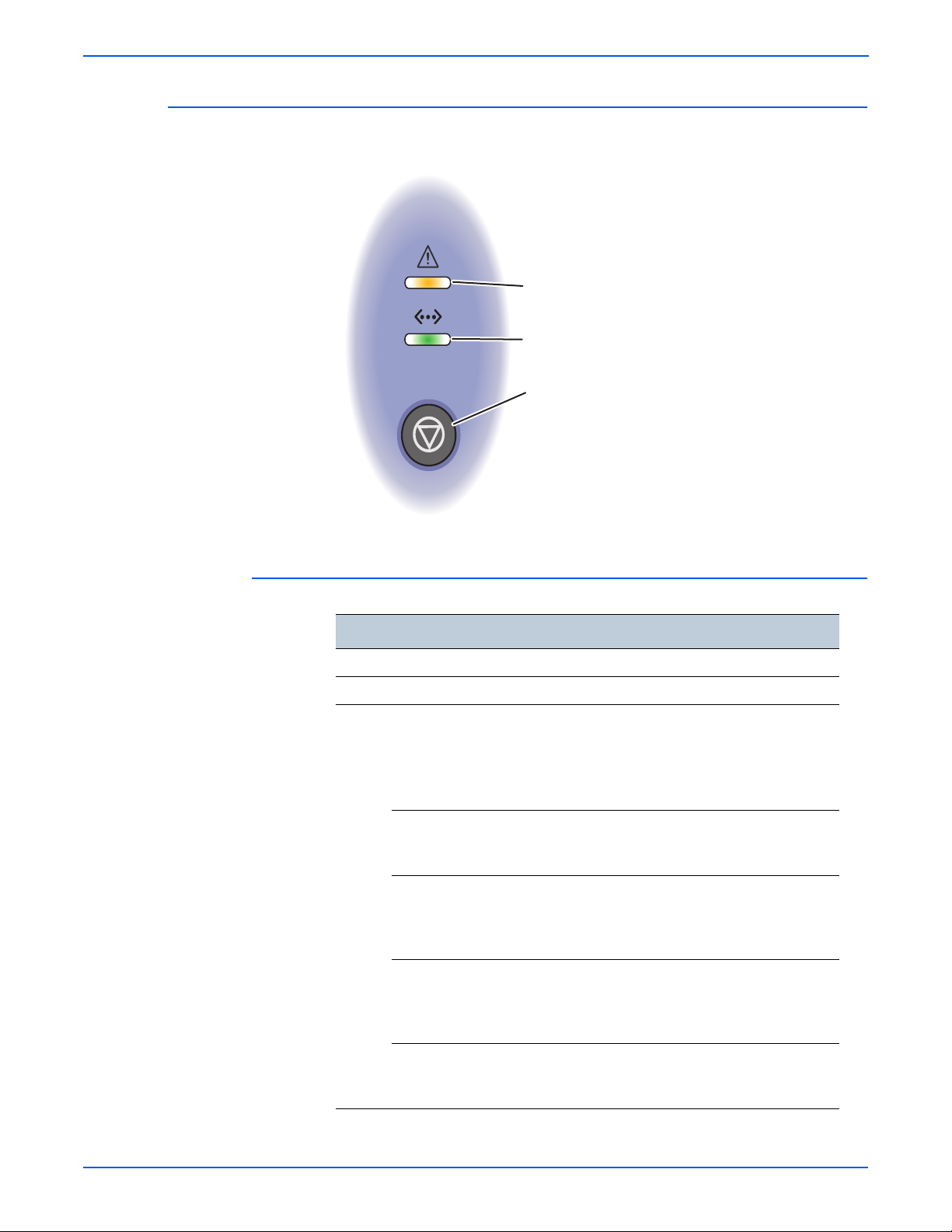
Error (Amber or Red)
LED
Online LED
Start/Stop Button
s3250-005
Control Panel
The Control Panel consists of 2 LEDs and 1 function button.
Control Panel Description
Description
1 Error: Indicates status of the printer.
2 Online: Indicates status of the printer.
3 Start/Stop button:
■ Prints a Demo page or Configuration page.
■ Cleans the Printer.
■ Cancels the print job.
■ Resumes a print job.
Print the Demo Page: In Ready mode, press and hold the Start/Stop
button until the bottom LED slowly blinks green, and then release
(approximately 2 seconds).
Print the Configuration page and Menu Map: In Ready mode, press
and hold the Start/Stop button until the bottom LED slowly blinks
green, then changes to fast blinking, and then release (approximately 6
seconds).
Clean the Printer: In Ready mode, press and hold the Start/Stop button
until the bottom LED slowly blinks (green), changes to fast blinking,
changes to slow blinking, and then release the Start/Stop button
(approximately 10 seconds).
Cancel a Print Job: In Ready mode, press the Start/Stop button.
■ Note: In Manual Feed mode, it is not possible to cancel the print job
by pressing the Start/Stop button.
1-6 Phaser 3250 Laser Printer Service Manual
Page 28

LED Indicators
Note
LED State Printer State
Green The printer is ready to print or in Power Save mode.
Amber Paper jam has occurred.
Red Error has occurred.
Flashing Red A minor error has occurred.
General Information
The printer is on-line.
The Print Cartridge is empty or is not installed.
The Print Cartridge toner is low.
Refer to “LED Status and Errors” on page 4-2, Chapter 4, Troubleshooting
Procedure for additional detailed information.
Phaser 3250 Laser Printer Service Manual 1-7
Page 29

General Information
Note
RAM DIMM
s3250-007
Printer Options
Additional Memory
The Phaser 3250 printer options include:
■ Additional Memory (128 MB)
■ 250-Sheet Feeder (Tray 2)
The standard 32 MB memory is soldered on board. The printer features one
memory slot that supports a 128 MB for a maximum of 160 MB. Memory
modules must meet the following characteristics:
■ 200 Pin DDR2 DIMM (8 chip type)
■ Unbuffered, Non-parity
The printer’s Configuration page lists the amount of RAM installed in the
printer.
Optional 250-Sheet Feeder (Tray 2)
The Optional 250-Sheet Feeder increases the input capacity of the printer and
can be attached to the printer underneath Tray 1. The Optional 250-Sheet
Feeder is customer installable.
Only one Optional 250-Sheet Feeder is supported.
1-8 Phaser 3250 Laser Printer Service Manual
Page 30

Maintenance Items
Note
s3250-051
Fuser
Transfer Roller
Pick-Up Roller
Tray Pad Holder
General Information
A maintenance item is a printer part or assembly that has a limited life, and
requires periodic replacement.
The following listed items have limited life and require periodic replacement.
Phaser 3250 Maintenance Items
Item Print Life
Fuser 50,000 pages
Pick-Up Roller (*) 50,000 pages
Transfer Roller (*) 50,000 pages
Tray Holder Pad 50,000 pages
(*) Customer Replaceable
Print life is based on “typical” office printing and 5% coverage per color on
24 lb. paper. The 50,000 life is not guaranteed and varies depending on
usage habits.
Phaser 3250 Laser Printer Service Manual 1-9
Page 31

General Information
s3250-016
Consumables
Consumables consist of 1 Print Cartridge used in the printer.
The Print Cartridge has a CRUM (Customer Replaceable Unit Meter) to
record the usage information. A CRUM counts the amount of remaining toner.
When toner empty is detected, Life End status will be sent to indicate toner
empty.
Life ratings are based on A4 (Letter) sheets at 5% coverage.
Print Cartridge
Standard Capacity 3,500 pages
High Capacity 5,000 pages
Print Life
1-10 Phaser 3250 Laser Printer Service Manual
Page 32

Specifications
Functional Specifications
General Information
Characteristic Specifications
Printing Technology Printing System: Laser Diode Unit and Electro-photographic
system
Developing System: Non-magnetic Contacting
Development System
Fusing System: Heat Roller heating by 750W Halogen
Lamp.
Printer Life 100,000 pages or 5 years
Average Monthly
Print Volume
(average)
Maximum Duty Cycle 30,000 pages/month*
Resolution Up to 1,200 x 1,200 dpi
Print-Quality Mode 600 x 600 dpi
Average Image
Coverage
Warm-Up Time 15 seconds
Operating System Windows 2000/ 2003 Server/ XP/ Vista
* Assumes a 30 day month of printing.
Memory Specifications
600 PV/month
For Duplex prints, prints on the front and back sides of
paper are counted as 2 PV.
5%
Mac OS 8.6~9.2 / OS 10.1~10.4
Linux Redhat 8~9, Fedora Core 1~4,
Mandrake 9.2~10.1, SuSE 8,2~9.2
Characteristic Specifications
Memory Minimum 32 MB on-board
Maximum 160 MB
Supported RAM Supports up to 160 MB of DDR2 DIMM with one slot
for 128 MB.
Phaser 3250 Laser Printer Service Manual 1-11
Page 33

General Information
Environmental Specifications
Characteristic
Temperature
Operating 10 to 32° C(50 to 90° F)
Storage (unpacked) 0 to 35° C (32 to 95° F)
Storage (packed) -20 to 40° C (-4 to 104° F)
Humidity (% RH)
Operating 10 to 80% RH
Storage (unpacked) 20 to 80% RH
Storage (packed) 20 to 95% RH
Altitude
Operating 2,500 meters (8,200 feet)
Acoustic Noise Level
Printing Less than
Standby Less than 25.0 dB(A)
Sound Power/Pressure (Decibels)
Simplex Duplex Tray 2
50.0 dB(A)
Specifications
Less than
54.0 dB(A)
Less than
55.0 dB(A)
Sleep Background Level
1-12 Phaser 3250 Laser Printer Service Manual
Page 34

Electrical Specifications
Characteristic Specifications
Power Supply Voltage/Frequency
Line Voltages 100-127 VAC -10% ~ +6%
Frequency Range 50/60 Hz ± 3 Hz
Current Capacity 110 V: 9.0A
Power Consumption AC 110 V AC 220 V
Standby 70 W or less 70 W or less
Sleep Mode 11 W or less 11 W or less
Average Less than 550 W Less than 550 W
In-rush Current
General Information
220-240 VAC -10% ~ +6%
220 V: 4.5A
Print Speed
At 25° Cold Start Less than 40 Amp
Hot Start 135 Amp
Other Conditions Less than 60 Amp
Leakage Current Less than 3.5 mA (UL)
Resolution Simplex (ppm) Duplex (ipm)
Letter 30 15
A4 28 14
Legal 24 10
B5 21 ----A5 15 ----A6 15 -----
Phaser 3250 Laser Printer Service Manual 1-13
Page 35

General Information
Operating Mode
The Phaser 3250 consists of the following operating modes:
■ Ready Mode: When the machine is turned On, it changes from the power
Off state to Ready mode. In this mode, printing is available.
■ Running Mode: The printer operates in the Print mode.
■ Save Mode: The Printer enters into the Save mode to reduce power
consumption when it has not received data for the specified time.
Information listed in the table provides description and statuses of the printer
modes at various states.
Operating Modes
Mode LED Status State
Ready Green The printer is ready.
Running Flashing Green In operation.
Save Green Printer idles at a specified time.
Warm-Up Time
Warm-up Time is defined as the time when the printer changes from PowerOn to Standby mode.
■ Standard Configuration: 15 seconds (from Sleep)
First Print Output Time
First Print Output Time (FPOT) is defined as the time from when the engine
receives a Start signal in Ready state, until a single page is printed and
delivered to the output tray.
Mode FPOT (sec.)
Ready Less than 8.5
Sleep Less than 23.5
Cold Start Less than 25.0
1-14 Phaser 3250 Laser Printer Service Manual
Page 36

Image Specifications
Note
■ Refer to “Print-Quality Troubleshooting” on page 5-1 for detailed
Print Margins
General Information
The printer has 4 mm margins on all sides. Edge-to-edge printing will not
be available.
troubleshooting.
Print Area Margin
Guaranteed Print
Quality Area
Printable Area Paper Width (A+B) A = Left Margin 3 mm
Characteristic Specifications
Skew
Vertical 241.3 mm (9.5 in.) ± 2.0 mm (.08 in.)
Horizontal 177.8 mm (7.0 in.) ± 1.5 mm (.06 in.)
Linearity
Paper Width (A+B) A = Left Margin 4.23 mm
B = Right Margin 4.23 mm
Paper Length
(C+D)
Paper Length
(C+D)
Tray 3, Duplex: 241.3 mm (9.5 in.) ± 2.5 mm (.09 in.)
Tray 3, Duplex: 241.3 mm (9.5 in.) ± 2.0 mm (.08 in.)
C = Top Margin 4.23 mm
D = Bottom Margin 4.23 mm
B = Right Margin 3 mm
C = Top Margin 3 mm
D = Bottom Margin 3 mm
Horizontal 200 mm (7.9 in.) ± 0.5 mm (.02 in.)
Magnification
Horizontal 177.8 mm (7.0 in.) ± 1.8 mm (.07 in.)
Vertical 241.3 mm (9.5 in.) ± 2.4 mm (.09 in.)
Registration
Left Print Position
(scanning direction)
Top Print Position
(feeding direction)
Phaser 3250 Laser Printer Service Manual 1-15
Simplex: 2.5 mm (.09 in.)
Duplex: 3.0 mm (1.2 in.)
Simplex: 3.0 mm (1.2 in.)
Duplex: 3.0 mm (1.2 in.)
Page 37

General Information
482.6 mm
(18.8 in.)
100 mm
(3.9 in.)
100 mm
(3.9 in.)
100 mm
(3.9 in.)
951.6 mm
(37.3 in.)
564 mm
(22.3 in.)
s3250-055
Physical Dimensions and Clearances
Printer Dimensions
Print Engine 3250D 3250DN
Height 198 mm (7.8 in.) 198 mm (7.8 in.)
Width 364 mm (14.3 in.) 364 mm (14.3 in.)
Depth 370 mm (14.5 in.) 370 mm (14.5 in.)
Weight (base printer with
standard fill print cartridge)
Optional 250-Sheet Feeder
Height 91.2 mm (3.6 in.) 91.2 mm (3.6 in.)
Width 363.0 mm (14.3 in.) 363.0 mm (14.3 in.)
Depth 402.5 mm (15.8 in.) 402.5 mm (15.8 in.)
Weight 2.62 kg (5.7 lb.) 2.62 kg (5.7 lb.)
Minimum Clearances
11.9 kg (26.2 lb.) 11.9 kg (26.2 lb.)
1-16 Phaser 3250 Laser Printer Service Manual
Page 38

Mounting Surface Specifications
s3250-009
100 mm
(3.9 in.)
100 mm
(3.9 in.)
100 mm
(3.9 in.)
482.6 mm (18.8 in.)
s3250-010
2 mm 2 mm
These specifications apply to any printer used as a table-top printer.
1. In order to function properly, the printer must be placed on a surface with
the following minimum dimensions.
General Information
2. Mounting surface flatness must be within the specified range. The printer
must not be tipped or tilted more than 2 mm.
Failure to adhere to the specified mounting specifications will void all
guarantees of print-quality and/or performance.
Phaser 3250 Laser Printer Service Manual 1-17
Page 39

General Information
Media and Tray Specifications
The following tables list the supported paper and media for the Phaser 3250.
Supported Paper Type and Size
Paper Type Paper Size Dimension
Plain Paper Letter 8.5 x 11 in.
(216 x 279 mm)
Legal 8.5 x 14 in.
(216 x 356 mm)
US Folio 8.5 x 13 in.
(216 x 330.2 mm)
Oficio 8.5 x 13.5 in.
(216 x 343 mm)
Executive 7.25 x 10.5 in.
(184 x 267 mm)
A4 8.26 x 11.69 in.
(210 x 297 mm)
A5 5.82 x 8.26 in.
(148 x 210 mm)
A6 4.13 x 5.82 in.
(105 x 148 mm)
B5 ISO 6.93 x 9.84 in.
(176 x 250 mm)
Manual
Feeder
Tray
1, 2
Yes Yes Yes
Yes Yes Yes
Yes Yes Yes
Yes Yes Yes
Yes Yes No
Yes Yes No
Yes Yes No
Yes Yes No
Duplex
B5 JIS 7.18 x 10.12 in.)
Yes Yes No
(182 x 257 mm
Custom Page Size* Yes Yes No
Transparency Letter, A4 Refer to Plain
Yes Yes Yes
Paper
Labels Letter, Legal, Folio,
Oficio, A4, JIS B5,
Refer to Plain
Paper
Yes No No
ISO B5, Executive,
A5, A6
Card Stock Letter, Legal, Folio,
Oficio, A4, JIS B5,
Refer to Plain
Paper
Yes No No
ISO B5, Executive,
A5, A6
Custom (minimum size) 3.86 x 5.83 in.
Yes No No
(76 x 127 mm)
Custom (maximum size) 8.5 x 14 in.
Yes No No
(215.9 x 356 mm)
* All trays support Custom sizes. The Manual Feeder supports a wider range of
Custom size dimensions than trays 1 and 2.
1-18 Phaser 3250 Laser Printer Service Manual
Page 40

Supported Paper Type and Weight
Paper Type Paper Weight
Manual
Feeder
General Information
Tray 1, 2 Duplex
Plain Paper 60-105 g/m
(16-28 lb. Bond)
60-163 g/m
(16-43 lb. Bond)
Labels 120-150 g/m
(32-40 lb.)
Card Stock 60-163 g/m
(16-43 lb.)
Transparency 138-146 g/m
Xerox Premium
Transparency
Envelope 75-90g/m
(20-24 lb.)
Custom 60-163 g/m
(16-43 lb.)
Supported Envelopes
Type Dimension
#10 Commercial
Envelope
4.12 x 9.5 in.
(105 x 241 mm)
2
2
2
2
2
2
2
Yes Yes Yes
Yes No No
Yes No No
Yes No No
Yes No No
Yes No No
Manual
Feeder
Tray 1 , 2 Duplex
Yes No No
Monarch Envelope 3.88 x 7.5 in.
Yes No No
(98.4 x 190.5 mm)
B5 Envelope 6.93 x 9.84 in.
Yes No No
(176 x 250 mm)
C5 Envelope 6.38 x 9.02 in.
Yes No No
(162 x 229 mm)
C6 Envelope 4.49 x 6.38 in.
Yes No No
(114 x 162 mm)
DL Envelope 4.33 x 8.66 in.
Yes No No
(110 x 220 mm)
Note: Do not use envelopes with hot melt glue, windows, or metal clasps.
Phaser 3250 Laser Printer Service Manual 1-19
Page 41

General Information
Non-Genuine Mode
When the Print Cartridge life has ended, the printer stops accepting print
request (life of the Print Cartridge is counted by the counter in the CRUM).
Print Cartridge Error Information
Print Cartridge
Xerox Red Replace Toner Stops printing.
Xerox Blinking Red Low Toner Prints with full
Non-Xerox Print
Cartridge
Manufacturer
Toner Remaining Amount
Toner remaining amount can be checked through CentreWare Internet
Services (CWIS), Configuration Page, or Supplies Info Page.
CentreWare IS View
LED Display
Red Invalid Toner Stops printing.
Status Monitor Functionality
functionality.
Maintenance Function
Firmware Update
The Main Controller Board firmware can be updated by customers and
service technicians using Windows PC or Macintosh with dedicated utilities.
Firmware updates are available at www.xerox.com/office/support.
Detailed procedures are available in the “Updating Firmware” on page A-3.
Updated Firmware Windows
Via USB/IEEE1284 Via Network (port 9100)
Main Controller Board Available Available
1-20 Phaser 3250 Laser Printer Service Manual
Page 42

Diagnostics
Power Save Mode
General Information
Two types of diagnostic functions are available:
1. Auto Diagnostics: The printer is checked when whether or not it is turned
On. It is checked whether or not hardware (ROM, RAM, ASIC, etc....)
operates properly.
2. Manual Diagnostics: Only qualified service personnel can perform manual
diagnostics.
The Power Save Mode is controlled by the main system firmware. In order to
switch the Ready state to the Power Save Mode after a specified time, the
main system sends a sleep command to the engine. When the engine
receives a sleep command, it stops the operation of the Fuser and the Fan
Unit in the engine. The main system then sets the engine to a sleep state.
User can adjust Power Save Mode for the Phaser 3250 printer. The Power
Save can be set from 5 to 120 minutes.
Printer Settings Utility View (USB Connection)
Phaser 3250 Laser Printer Service Manual 1-21
Page 43

General Information
CentreWare IS View (Network Connection)
1-22 Phaser 3250 Laser Printer Service Manual
Page 44

Printer Settings Utility
Accessing Printer Settings Utility
General Information
The Printer Settings Utility enables user to monitor the printer’s status. User
can use the Printer Settings Utility to add and/or update the printer’s
information as needed.
1. From the Start Menu, select Programs > Xerox P3250 > Printer
Settings Utility.
2. The Printer Settings Utility window is displayed.
3. Information contained in the Printer Settings Utility include:
■ Information: Print Configuration Page, Print Demon Page
■ Setting: Power Save, Auto Continue, Altitude Adjustment, Auto CR,
Job Timeout, Toner Save, Emulation Type
■ Layout: Orientation, Simplex Margin, Duplex, Duplex Margin
■ Paper Option: Copies, Paper Size, Paper Type, Paper Source, Tray
Chaining
■ Graphic: Resolution, Darkness, Image Enhance
■ Emulation: Emulation Setting
■ Network: Configuration Network, Print Network Configuration
■ About
Phaser 3250 Laser Printer Service Manual 1-23
Page 45

General Information
CentreWare IS
Accessing the CentreWare IS
The CentreWare IS enables the user to monitor the printer’s status. User can
access the CentreWare IS menu to add and/or update the printer’s
information as needed.
1. Open a web browser.
2. Enter the printer’s IP address.
3. The CentreWare IS page is displayed.
4. Various printer information are located under different categories:
■ Status: Provides General Status information of the printer.
■ Print: Prints Help pages.
■ Properties: Provides general information about the printer including
Version Information, Memory, Page Description Languages, and
Printer Options.
■ Troubleshoot: Provides list of embedded pages including Menu Map,
PostScript Font List, PCL Font List, and Print Cleaning Page.
■ Support: Provides web links and information for support including
Software, Documentation, Supplies, and Registration.
1-24 Phaser 3250 Laser Printer Service Manual
Page 46

General Information
The Index provides additional detailed information on the printer.
Phaser 3250 Laser Printer Service Manual 1-25
Page 47

General Information
Reports and Information Pages
The following reports and information pages are available in the Phaser 3250
printer. The embedded pages can be printed using various methods.
Report/Information Page Print Method
Printer Settings
Control Panel
Demo Page Yes Yes Yes
Menu Map Yes No Yes
Printer Configuration Page Yes Yes Yes
Network Configuration Page No Yes Yes
Event Log Yes No No
Supplies Info Yes No No
PCL Font List No Yes Yes
PostScript Font List No Yes Yes
Print Cleaning Page Yes No Yes
Utility (USB)
CentreWare IS
(Network)
1-26 Phaser 3250 Laser Printer Service Manual
Page 48

Control Panel Method
Embedded
Pages
Blinking
Rate
Slowly
2 seconds
For Customer
(in the User Guide)
Only for Service Technician
(in the Service Manual)
5 seconds 10 seconds 15 seconds
Quickly Slowly Quickly
Approx.
Release
Time
Demo Page Print
Cleaning Page
Event Log and
Supplies
Information
Configuration
Page and
Menu Map
s3250-074
To print various report/information page from the Control Panel, press and
hold the Start/Stop button for a specific amount of time and release the Start/
Stop button.
Report/Information Page Time (second) LED Status
Demo page 0~2 Blinks slowly
Configuration Page and Menu Map 0~5 Blinks quickly
Print Cleaning Page 0~10 Blinks slowly
Supplies Info and Event Log 0~15 Blinks quickly
General Information
Phaser 3250 Laser Printer Service Manual 1-27
Page 49

General Information
CentreWare IS Method (Network)
1. Open a web browser.
2. Enter the printer’s IP address.
3. The CentreWare IS page is displayed.
4. Click the Index button.
5. Click the appropriate page link to be printed.
■ Print Cleaning Page
■ Print Configuration Pages
■ Print Demo Page
■ Print Diagnostics Pages
■ Print Help Pages
1-28 Phaser 3250 Laser Printer Service Manual
Page 50

Print Cleaning Page
Print Configuration Pages
Print Demo Page
General Information
Print Diagnostics Pages
Print Help Pages
Phaser 3250 Laser Printer Service Manual 1-29
Page 51

General Information
6. Select the appropriate page to be printed.
7. Click the Blue button.
8. The status window is displayed. Click OK to close the window. Close the
CentreWare IS window.
9. The Green LED on the Control Panel starts blinking and a printable page
is printed.
1-30 Phaser 3250 Laser Printer Service Manual
Page 52

Printer Settings Utility Method (USB Connection)
1. From the Start Menu, select Programs > Xerox P3250 > Printer
Settings Utility.
2. The Printer Settings Utility window is displayed.
a. On the left side of the page, select Information or Network.
b. On the right column of the window, Information is displayed.
3. Select the appropriate page to be printed and click the Print button.
■ Information: Prints the Configuration Page or Print Demo Page.
■ Network: Prints the Network Configuration.
General Information
Phaser 3250 Laser Printer Service Manual 1-31
Page 53

General Information
Demo Page
The Demo Page provides sample print for the Phaser 3250 Laser Printer.
1-32 Phaser 3250 Laser Printer Service Manual
Page 54

Menu Map
General Information
The Menu Map lists all the available functions of the printer.
Menu Map Information
General Description Detail Description
1. Information Menu Map, Configuration, Demo Page, PCL Font
List, PostScrip 3 Font List, EPSON Font
2. Layout Orientation, Simplex Margin, Duplex, Duplex Margin
3. Paper Copies, Paper Size, Paper Type, Paper Source
4. Graphic Resolution, Darkness, Image Enhance
5. System Setup Language, Power Save, Auto Continue, Altitude Adj,
Auto CR, Job Timeout, Toner Save, Maintenance,
Clear Setting
6. Emulation Emulation Type, Setup
7. Network TCP/IP, EtherTalk, Ethernet Speed, Clear Setting,
Network Info.
PCL (-) Typeface, Symbol, Courier, Pitch, Lines
PostScript (-) Print PS Error
EPSON (-) Font, Character Set, Character Tab, Pitch, LPI, Auto
Wrap
Phaser 3250 Laser Printer Service Manual 1-33
Page 55

General Information
Configuration Page
The Configuration page contains configuration information for the printer. Two
types of Configuration page are available: Printer Configuration page and
Network Configuration.
Printer Configuration Page Information
General Description Detail Description
Printer Information Total Page Counts, Firmware Version, Engine
Version, USB SN, PCL5E Version, PCL6 Version, PS
Version, EPSON Version, SPL Version, Tray2 Version
Memory Information Total Memory Size, Base Memory Size
Cartridge Information Toner Remaining, Page Counts, Model ID, Capacity,
Supplier, Product Date
Network Card NIC Firmware Version, MAC Address, IP Address,
SubNet Mask, Default Gateway
Install Options Option Tray Installed/Option Tray Not Installed
1-34 Phaser 3250 Laser Printer Service Manual
Page 56

General Information
Network Configuration Page Information
General Description Detail Description
General Information Host Name, Contact, Location, MAC Address, NIC F/W
Version, Network Connection Status
TCP/IP Information IP Assignment, IP Address, SubNet Mask, Default
Gateway
IPP Information IPP Protocol, Printer URI, Authentication Scheme
Raw TCP/IP Printing
Information
LPD Information LPD Printing, Port Number
SLP Information SLP Protocol, SLP Multicast TTL, Port Number
IP Filtering Information IP Filtering
UPnP Information Auto IP, SSDP, SSDP TTL
EtherTalk Information EtherTalk Protocol, Printer Name, Printer Type, Current
Raw TCP/IP Printing, Port Number
Zone
Phaser 3250 Laser Printer Service Manual 1-35
Page 57

General Information
Event Log
The user can print the Event Log on A size paper from the default tray. The
Event Log contains:
■ Event Log Info
■ Toner Event Log
■ Error Counts
Detailed information on the Event Log Info and Error Counts include:
■ Event Log Info (##): Page number where the error occurs
■ Error Counts (#): Number of error per the type of error
1-36 Phaser 3250 Laser Printer Service Manual
Page 58

Supplies Info
General Information
The user can print the Supplies Info page on A-size paper from the default
tray. The Supplies Info page contains:
■ Cartridge Information: Cartridge Status, Equivalent Pages Printed, Dot
Counts, Page Counts, Main Motor On Time, Clear Toner, Replaced Toner
Counts, Model ID, Capacity, Supplier, Product Date, Serial Number
■ Toner Event Log
Page Count
Page Count information is available through CentreWare IS.
Phaser 3250 Laser Printer Service Manual 1-37
Page 59

General Information
Print Cleaning Page
The Print Cleaning page is printed when a Cleaning procedure is performed.
There are two methods for printing the Print Cartridge Cleaning page.
■ Control Panel Method - refer to “Control Panel Method” on page 1-27
(Chapter 1, General Information).
■ CentreWare IS Method - refer to “Printing the Print Cleaning Page” on
page 7-5 (Chapter 7, Cleaning and Maintenance).
1-38 Phaser 3250 Laser Printer Service Manual
Page 60

PCL Font List
PS Font List
General Information
The user can print the PCL Fonts List on A-size paper from the default tray.
The PCL Font List contains:
■ Font Number, Font Name, Pitch/Point, Escape Sequence
The user can print the PostScript Font List on A-size paper from the default
tray.
Phaser 3250 Laser Printer Service Manual 1-39
Page 61

General Information
1-40 Phaser 3250 Laser Printer Service Manual
Page 62

Theory of Operation
In this chapter...
■ Phaser 3250 Operational Overview
■ Paper Path of the Printer
■ Major Assemblies and Functions
■ Electrical Components
Chapter
2
Page 63

Theory of Operation
Phaser 3250 Operational Overview
The Phaser 3250 is a monochrome laser printer that uses Laser Scanner Unit
(LSU) with an electrophotographic process. The printer system consists of
one print cartridge which creates toner image.
System Overview
The Phaser 3250 Laser Printer consists of the Feeding Mechanism, Drive
Assembly, Transfer Roller, Fuser, Laser Unit, Control Panel, and Printer
Controller.
■ Feeding Mechanism: The Feeding mechanism consists of the Manual
Feeder, Tray 1, Tray 2, Pick-Up Roller, Tray Holder Pad, and Feed Rollers.
The rollers and sensors in the paper feed path control paper registration
and guide the paper through the image transfer, image development,
image fusing, and exit assemblies.
■ Drive Assembly: The Drive Assembly receives power from the Main
Controller Board, The Main Motor provides drive energy to the paper feed,
Toner Cartridge, Fuser, Pick-Up Roller, Feed Rollers, and Duplex Unit.
The Drive Assembly consists of a Main Motor.
■ Main Motor: DC 24V
■ Rated RPM: 2170 rpm
■ Transfer Roller: The Transfer Roller transfers toner on an Organic Photo
Conductor (OPC) to the paper.
■ Fuser: The Fuser consists of a Heat Lamp, Heat Roller, Pressure Roller,
Thermistor, and Thermostat. The Fuser applies toner on to paper using
heat and pressure.
■ Laser Unit: The Laser Unit is an exposure unit that generates laser
beams to form electrostatic latent image on the drum surface.
■ Control Panel: The Control Panel displays LED status of the printer.
■ Printer Controller: The Printer Controller controls the total system of the
machine. The Printer Controller processes and stores images from the
Print Engine, printer I/F, and controls the panel.
2-2 Phaser 3250 Laser Printer Service Manual
Page 64

Paper Path of the Printer
Laser Unit
Developer
Tray 1
Duplex
Fuser
s3250-011
Theory of Operation
The media is supplied from the Manual Feeder, Tray 1, or Tray 2, and is
transported through the printer as shown.
Paper Feeding
Separation Method
Paper feeding consists of the Manual Feeder, Tray 1, Tray 2, Duplex Unit, and
components relating to paper transferring. The Rollers and Sensors in the
paper feed path control paper registration and guide the paper through the
image transfer, image development, image fusing, and exit assemblies. The
paper path has an anti-static connection to ground to eliminate problems due
to static charge on the paper.
Individual sheets are separated from the Friction Pad in the tray. When paper
feeds into the printer, it passes over a spring loaded Friction Pad that
separates the sheets of paper.
Phaser 3250 Laser Printer Service Manual 2-3
Page 65

Theory of Operation
Holder Pad
Paper Guide
Paper Guide
Rear Paper Guide
Knock Up P Plate
s3250-012
Paper Tray
The paper tray uses a “center loading” method. The paper tray has Side and
Rear Guides which can be adjusted for various paper sizes. A paper level
indicator, located in front of Tray 1 and Tray 2, indicates the amount of
remaining paper.
The paper tray also has a paper detecting functions which includes Existence
Sensing function, Paper Arranging function, Various Size Papers Accepting
function, Tray 2 Paper Path function, and Displaying Remaining of Paper
function.
2-4 Phaser 3250 Laser Printer Service Manual
Page 66

Pick-Up Roller
s3250-013
s3250-042
s3250-043
The Pick-Up Roller is used to pick up and feed paper into the printer and
remove static charge on the paper.
Theory of Operation
Feed Roller (Registration)
The Feed Roller arranges paper, transfers paper, detects paper, and removes
jam.
Feed Roller (top area of the printer)
Feed Roller (bottom area of the printer)
Phaser 3250 Laser Printer Service Manual 2-5
Page 67

Theory of Operation
s3250-044
s3250-006
Manual Feeder
The Manual Feeder is used to hold non-standard or custom paper sizes and
special media (envelopes, transparencies, etc.). The Manual Feeder uses a
friction pad method to ensure paper is separated and can only hold 1 sheet of
paper.
Duplex Unit
The Duplex Unit can be installed without using any tools. The Duplex Unit
uses a side feeding method. When a jam occurred in the front or rear part of
the printer, the Duplex Unit can be removed to access the jam area.
2-6 Phaser 3250 Laser Printer Service Manual
Page 68

Tray 2 (Optional Tray)
s3250-007
The Optional Tray 2 is universal with Tray 1 and has a capacity of 250 sheets.
Tray 2 has a separate driving mechanism.
Theory of Operation
Phaser 3250 Laser Printer Service Manual 2-7
Page 69

Theory of Operation
s3250-045
1
5
3
7
6
2
4
s3250-072
Major Assemblies and Functions
Transfer Roller
The Transfer Roller transfers toner on an Organic Photo Conductor (OPC) to
the paper.
Drive Assembly
The Drive Assembly receives power from the Main Controller Board, The
Main Motor provides drive energy to the paper feed, Toner Cartridge, Fuser,
Pick-Up Roller, Feed Rollers, and Duplex Unit. The Drive Assembly consists
of a Main Motor.
■ Main Motor: DC 24V
■ Rated RPM: 2170 rpm
2-8 Phaser 3250 Laser Printer Service Manual
Page 70

Fuser
s3250-014
Thermistor
Thermostat
Heat Roller
Pressure Roller
Halogen Lamp
(inside Heat Roller)
Pressure Roller
(behind Heat Roller)
s3250-107
Theory of Operation
The Fuser uses a heat lamp process. The Fuser consists of a Halogen Lamp,
Heat Roller, 2 Pressure Rollers, Thermistor, and Thermostat. Toner is melted
to adhere to the paper surface by heat and pressure process.
Fuser Components
Halogen Lamp
■ Voltage
■ 120V: 115 ± 5%
■ 220V: 230 ± 5%
■ Capacity: 750 Watt ± 25 W
Phaser 3250 Laser Printer Service Manual 2-9
■ Temperature Distribution: 120%
Page 71

Theory of Operation
Thermistor (Temperature Detecting Sensor)
The Thermistor is used to detect the temperature of the heating unit and feeds
this data into the main processor.
Thermostat (Heat Lamp Power Cut-Off)
When the Heat Lamp becomes too hot, the Thermostat cuts off power to the
Lamp to prevent from overheating.
Heat Roller
The Heat Roller transfers heat from the Lamp to the paper. As the paper
passes between the Heat Roller and Pressure Rollers, the toner is melted and
permanently fixed to the paper. The surface of the Heat Roller is coated with
Teflon, so that toner does not stick to the surface.
Pressure Roller
The Pressure Roller, mounted under a Heat Roller, is made of a silicon resin
and the surface is also coated with Teflon. When paper passes between the
Heat Roller and the Pressure Roller, toner powder is melted and permanently
fixed to the surface of the paper.
Safety Features
To Prevent Overheating:
■ 1st Protection Device: Hardware cuts off when overheated.
■ 2nd Protection Device: Software cuts off when overheated.
■ 3rd Protection Device: Thermostat cuts off main power to the Lamp.
Safety Device:
■ Fuser power is cut off when the Front Cover is opened.
■ Laser power is cut off when the Front Cover is opened.
■ The temperature of the Fuser cover’s surface is maintained at less than
80°
to protect the user. A Caution label is attached where the customer
can easily see when the Rear Cover is opened.
2-10 Phaser 3250 Laser Printer Service Manual
Page 72

Laser Unit
s3250-015
Theory of Operation
The Laser Unit is the core part of the Phaser 3250 and is controlled by a video
controller. The Laser Unit converts video data received from the computer into
an electrostatic latent image on the surface of the OPC Drum. This is
achieved by controlling the laser beam and exposing the surface of the OPC
Drum to the laser light. A rotating polygon mirror reflects the laser light onto
the OPC. Each face of the mirror produces one scan line. The OPC Drum
rotates at the same as the paper feeding speed. As the OPC Drum turns, the
laser scans, which creates the full page image.
The Horizontal Sync (HSYNC) signal is created when the laser beam from the
Laser Unit reaches the end of the polygon mirror and this signal is sent to the
controller. The controller detects the HSYNC signal to adjust the vertical line
of the image on paper. In other words, after the HYSNC signal is detected, the
image data is sent to the Laser Unit to adjust the left margin on the paper.
Phaser 3250 Laser Printer Service Manual 2-11
Page 73

Theory of Operation
s3250-016
-1.25 ~ -1.45KV
s3250-073
Laser Scanning Unit (LSU)
0.20 mW
Charging Roller
Cleaning Blade
Transfer Roller
Developing
Roller
Supply Roller
Cleaning Roller
OPC Drum
Doctor Blade
Pre-Transfer Lamp
(PTL)
Max. +4.2kV
V
0
: -750V
V
L
: -130V
V
s
: -680V
V
D
: -430V
-+
-250V
Print Cartridge
The Print Cartridge is an integral unit containing the OPC Unit and toner unit.
The OPC Unit consists of the OPC Drum and Charging Roller. The Print
Cartridge consists of toner, Toner Cartridge, Supply Roller, Developing Roller,
and Blade (Doctor Blade).
■ Developing Method: Non-contacting method
■ Toner: Non magnetic 1 component pulverized type toner
■ Toner Life: 3,500 pages/5,000 pages (ISO19752 standard)
■ Toner Remaining Sensor: Yes
■ OPC Cleaning: Cleaning blade type
■ Management of Waste Toner: Collects toner using the Cleaning Blade.
■ OPC Drum Protecting Shutter: No
■ Toner CRUM Reader: Identifies whether toner is Xerox branded toner or
whether a Non-Xerox toner cartridge is installed in the printer, except for
the initial cartridge.
2-12 Phaser 3250 Laser Printer Service Manual
Page 74

Electrical Components
s3250-028
Ethernet IC
U18 NOR FLASH
U17 NOR FLASH
U8 ASIC
DC to DC
Converter, 1.3V
DC to DC
Converter, 3.3V
U3 EEPROM
U4 EEPROM
U6 SDRAM
U7 SDRAM
USB IC
Main Controller Board
Theory of Operation
The Engine Board and the Controller Board have been integrated into one
Main Controller Board, which consists of the CPU and printer control
functions. The CPU functions as the bus control, I/O handling, drivers, and PC
interface. The Main Controller Board sends the current image video data to
the Laser Unit and manages the electrophotographic printing process.
Circuits on the Main Controller Board drive the Main Motor (paper feed),
Clutch, Pre-Transfer Lamp, Heat Lamp, and Fan.
The signals from the Paper Feed Jam Sensor and Paper Empty Sensor are
inputted to the Main Controller Board.
Phaser 3250 Laser Printer Service Manual 2-13
Page 75

Theory of Operation
Asic (SPGPv3)
CPU Core: ARM1020E
■ 32KB instruction cache and 32 KB data cache
Operating Frequency
■ CPU Core: Over 300 MHz
■ System Bus: 100 MHz
SDRAMC
■ 32 Bits only, 100 MHz
■ 5 Banks (up to 128 MB per Bank)
ROMC
■ 4 Banks (up to 16 MB per Bank)
IOC
■ 6 Banks (up to 16 per Bank)
DMAC
■ 4 channels
HPVC
■ Dual/Single Beam
■ LVDS Pad (VDO, HSYNC)
UART
■ 5 channels (1 channel supports DMA operation)
PCI Controller
■ 32 Bits, 33/66 MHz
■ PCI Local Bus specification rev2.2 Compliant
■ Host/Agent Mode (supports 4 devices in Host mode)
NAND Flash Controller
■ 8/16 Bits, H/W EEC Generation
■ Auto Boot Mode (using Internal SRAM, 4 KB)
MAC
■ 10 M/100 Mbps
■ Full IEEE 802.3 compatibility
2-14 Phaser 3250 Laser Printer Service Manual
Page 76

Memory
RAM DIMM
Theory of Operation
Engine Controller
■ Laser Unit interface
■ Step Motor: 2 channels
■ PWM: 8 channels
■ ADC: 6 channels
I2C Controller
■ I2C (S-BUS) Slave Device Support (I2C version 2.1)
RTC
■ RTC Core Voltage: 3 V
PLL
■ 3 PLL: Main, PCI, PVC
The Main Controller Board has Flash ROM and DRAM memory units.
■ Flash Memory: Stores System Program and downloads the System
Program through PC Interface.
■ Capacity: 16 MB (NOR Flash)
■ Random Access Time: 10 us (max.)
■ Serial Page Access Time: 50 ns (min.)
■ DRAM: It is used as Swath Buffer, System Working Memory Area, while
printing. DRAM also stores Font List, compresses into Flash memory on
DRAM, and uses it as PCL font for export based on printer configuration.
■ Capacity: 32 MB (basic), up to 160 MB (factory option)
■ Type: SDRAM 100 MHz/133 MHz, 32 Bit
Phaser 3250 Laser Printer Service Manual 2-15
Page 77

Theory of Operation
Exit Sensor Actuator
s3250-018
Sensor Input Circuit
Paper Empty Sensing
The Paper Empty Sensor (Photo Interrupter) on the High-Voltage Power
Supply (HVPS) provides the state of paper to the CPU whether the tray is
empty or not when the Actuator is in operation. When the tray is empty, the
Paper Empty Sensor detects E20 of the CPU and then flashes the red LED on
the printer’s Control Panel.
Paper Feeding with Print Cartridge Sensing
When paper passes the Actuator on the Feed Sensor, it detects the signal of
the Photo Interrupter, sends the paper feeding state to the CPU, and starts
creating the image after a specified delay time.
If the Feed Sensor is not detected within one second after paper is fed, a
paper Jam0 occurs, while the amber LED is lit on the printer’s Control Panel.
After the Print Cartridge is installed, the sub CRUM reads the data of the Print
Cartridge from contacting with the CRUM involved in the Print Cartridge. If the
data of the Print Cartridge is invalid, the red LED is lit on the printer’s Control
Panel.
Paper Exit Sensing
This detects that paper exits cleanly from the printer using an Exit Sensor on
the HVPS and Actuator on the printer frame. Paper detects the On/Off time of
the Exit Sensor by reading D22 of the CPU, and the normal operation or a jam
status is reported. If a Jam2 error occurs, the amber LED is lit on the printer’s
Control Panel.
2-16 Phaser 3250 Laser Printer Service Manual
Page 78

Theory of Operation
Front Cover Open Sensing
The Front Cover Sensor is located on the HVPS. When the Front Cover is
open, +24 V that is supplied to the DC Fan, Solenoid, Main Motor, Polygon
Motor in the Laser Unit, HVPS, and Laser Diode are cut off. When the Front
Cover is open, the red LED is lit on the printer’s Control Panel.
DC Fan/Solenoid Driving
It is driven by transistor and controlled by the Main Fan (D14), Duplex Fan
(E16), Pick-Up Clutch (C23), Regi Clutch (C18), and the Manual Feeder
Clutch (D15) of the CPU.
When it is high, the Transistor turns On and drives the Fan, and it is Off when
Sleep mode is selected. There are three Solenoids, and they are driven by
paper Pick-Up, Regi, and Manual Feeder signals. It is turned On or Off by
C23, C18, and D15 of the CPU.
The diode protects the driving Transistor from the noise pulse, which is
created when the Solenoid is de-energizing.
The Fan Driving Circuit is driven by the Transistor and controls D14 and E16
of the CPU.
Motor Driving Circuit
The main motor driving circuits are located on the Brush-less Direct Current
(BLDC) Motor Assembly. The Motor Assembly Control Board contains a Motor
Driver IC.
The Exit Motor Driving Circuit is formed when the driver IC is selected. The
AN44060A Motor Driver IC is used in this case. The resistance Rs value for
sensing and voltage value for the V reference can be changed by motor
driving voltage value. The motor driving voltage is calculated with the following
formula:
IN 0, 2 IN 1, 3 Output Current
L L Vref / (10*Rs) = lout
H L Vref / (15*Rs) = lout * 2/3
L H Vref / (30*Rs) = lout *1/3
H H 0
The motor driving circuit is formed when the driver IC is selected. The A3977
Motor Driver IC is used in this case. The resistance Rs value for sensing and
voltage value for the V reference can be changed by the motor driving voltage
value.
■ I = Vref / Rs, wherein Vref is (R1 x 5V) / (R1+R2)
Phaser 3250 Laser Printer Service Manual 2-17
Page 79

Theory of Operation
A
132
133
134
135
136
137
138
139
140
141
142
143
144
145
131
BCDEFGHIJKL
s3250-019
CN1 Main Controller Board
Front Cover Open Switch
Rear Cover
Open Switch
THV
Varistor
Supply
Developer
OPC
MHV
High-Voltage Power Supply (HVPS)
The HVPS uses 24 V and outputs high voltage for the THV/MHV/BIAS and
the outputted high voltage is supplied to the toner, OPC Cartridge, and
Transfer Roller.
2-18 Phaser 3250 Laser Printer Service Manual
Page 80

Transfer High Voltage (THV+)
The (+) Transfer High Voltage is supplied to the Transfer Roller for transferring
toner onto the OPC Drum to the paper.
■ Input Voltage: 24 VDC ± 15%
■ Output Voltage:
■ MAX +5.0KV ± 5% (duty variable, no loading)
■ -1.2KV ± 15% (when cleaning, 200 M Ω)
■ Output Voltage Trigger: 6.5 uA
■ Input Contrast of the Voltage Stability Degree: Under ± 3% (fluctuating
input 21.6 V ~ 26.4 V0
■ Loading Contrast: ± 5% or less
■ Output Voltage Rising Time: 50 ms Max
■ Output Voltage Falling Time: 100 ms Max
Theory of Operation
■ Fluctuating Transfer Voltage with Environmental Various: 0 ~ 5 KV
■ Environment Recognition Control Method: The THV-PWM ACTIVE is
transfer active signal. It detects the resistance by recognizing the voltage
value, F/B, while permits the environmental recognition voltage.
■ Output Voltage Control Method: Transfer Output Voltage is outputted
and controlled by changing Duty of THV/PWM signal.
Charge Voltage (MHV)
The High Voltage is supplied to the OPC Drum through the Charging Roller
while charging the skin of the OPC Drum.
■ Input Voltage: 24 VDC ± 15%
■ Output Voltage: -1.0 KV ~ -1.8 VDC ± 3%
■ Output Voltage Riding Time: 50 ms Max
■ Output Voltage Failing Time: 50 ms Max
■ Output Loading Range: 30 M Ω ~ 1000 M Ω
■ Output Control Signal (MHV-PWM): CPU is HV output when PWM is Low.
Phaser 3250 Laser Printer Service Manual 2-19
Page 81

Theory of Operation
Cleaning Voltage (THV-)
The (-) Transfer High Voltage is supplied to the Transfer Roller to remove the
remaining toner from the OPC Drum.
■ The (+) Transfer Voltage is not outputted because the THV PWM is
controlled with high.
■ The (-) Transfer Voltage is outputted because the THF-Enable Signal is
controlled with low.
■ The output fluctuation range is large because there is no feedback
control.
Developing Voltage (DEV)
The Developing Voltage is supplied to the Developer Roller to transfer to the
toner to the charge on the OPC Drum scanned by the laser beam while
printing the image. The engine controls whether the high voltage is supplied
and its quantity.
■ Input Voltage: 24 VDC ± 15%
Supply
■ Output Voltage: -200 V ~ 600 V DC ± 3%
■ Output Voltage Fluctuation Range: PWM Control
■ Input Contrast of the Output Stability Degree: ± 3% or less
Loading Contrast: ± 3% or less
■ Output Voltage Rising Time: 50 ms Max
■ Output Voltage Failing Time: 50 ms Max
■ Output Loading Range: 10 M Ω ~ 1000 M Ω
■ Output Control Signal (BIAS-PWM): The CPU output is HV output when
PWM is low.
■ Output Voltage: -400 C ~ 800 VDC ± 50 V (ZENER using, DEV)
■ Input Contrast of the Output Stability Degree: Under ± 5%
■ Loading Contrast: ± 5% or less
■ Output Voltage Rising Time: 50 ms Max
■ Output Voltage Failing Time: 50 ms Max
■ Output Loading Range: 10 M Ω ~ 1000 M Ω
■ Output Control Signal (BIAS-PWM): The CPU is HV output when PWM is
low.
2-20 Phaser 3250 Laser Printer Service Manual
Page 82

Low-Voltage Power Supply (LVPS) (SMPS)
s3250-020
CON1 AC Inlet
CON2 Fuser
CON3 Main Board
A
132
133
134
135
136
137
138
139
140
141
142
143
144
145
131
BCDEFGHIJKL
The LVPS is the power source for the entire printer system. The LVPS
supplies DC power for driving the printer, and the AC heater control, which
supplies power to the Fuser.
The LVPS has two output channels: +5.0 V and +24 V.
Theory of Operation
Phaser 3250 Laser Printer Service Manual 2-21
Page 83

Theory of Operation
AC Input
■ Input Rated Voltage:
■ AC 220 V~240 V
■ AC 110 V~127 V
■ Input Voltage Fluctuation Range:
■ AC 198 V~264 V
■ AC 99 V~135 V
■ Rated Frequency Fluctuating Range: 47~63 Hz
■ Input Current: Under 4.0 Arms/2.0 Arms (when the e-coil is Off or rated
voltage is inputted/outputted)
Rated Output Power
No. Item CH1 CH2 Remark
1 CHANNEL NAME +5.0 V +24.0 V
2 CONNECTOR PIN CON 35V PIN: 11,
13, 15
GND PIN: 12, 14, 16
3 Rated Output +5 V ± 5%
(4.75~5.25 V)
CON 324V PIN: 3, 5,
7, 9
GND PIN: 4, 6, 8, 10
+24 V ± 10%
(21.6~26.4 V)
4 Max. Output Current 3 A 4.4 A
5 Peak Loading Current 3.6 A 5.3 A 1ms
6 RIPPLE NOISE
100mVp-p Under 500mVp-p
Voltage
7 Maximum Output 15 W 105.6 W
8 Peak Output 18 W 127.2 W 1ms
9 Protection for
Loading Shortage
Shut down or Fuse
Protection
Shut down or Output
Voltage Drop
and Overflowing
Current
2-22 Phaser 3250 Laser Printer Service Manual
Page 84

Power Consumption
No. Item System
1 Standby Less than 70 W
2 Printing Less than 550 W
3 Sleep Mode Less than 11 W
■ Length of Power Cord: 1830 ± 50 mm (72.0 ± 1.9 in.)
■ Power Switch: Use
■ Feature:
■ Insulating Resistance: 100 M Ω or more (at DC 500 V)
■ Withstanding Voltage: Must be no problem within 1 min.
■ Leaking Current: Under 3.5 mA
■ Running Current:
Theory of Operation
(at 1000V-LV model/1500Vac-HV model, 10 mA)
■ Rising Time: Within 2 Sec.
■ Falling Tine: Over 20 ms
■ Surge: Bi-Wave 3kV - Normal, 6kV - Common
Fuser AC Power Control
The Fuser receives heat from AC power, which controls the switch with the
Triac, a semiconductor switch. The On/Off control is operated when the gate
of the Triac is turned On/Off by Phototriac (insulting part). In other words, the
AC control part is passive circuit, so it turns the heater On/Off while retrieving
signal from the engine control part.
When the Heater On signal is turned On at the print engine, the LED of
PC501 (Photo Triac) measures the voltage and flashes. From the flashing
light, the Triac part (light receiving part) measures the voltage, and the voltage
is supplied to the gate of Triac and flows into the Triac. As the result, the AC
current flows in the Lamp, and heat is generated.
On the other hand, when the signal is Off, the PC501 is Off, the Triac is cut off
at the gate of Triac. When the Triac turns Off, the Lamp is turned Off.
* Under 40 A PEAK (at 25° C, COLD START)
* Under 60 A PEAK (in other conditions)
■ Triac (Q501) Feature: 24A-LV model/16A-HV model, 600 V Switching
■ Phototriac Coupler (PC501)
■ Turn On if Current: 15 mA~50 mA (Design: 16 mA)
■ High Repetitive Peak Off State Voltage: Min 600 V
Phaser 3250 Laser Printer Service Manual 2-23
Page 85

Theory of Operation
Engine F/W
Control Algorithm
Feeding
When feeding from a paper tray, the drive of the Pick-Up Roller is controlled
by the Solenoid.
The printer feeds the paper from the Manual Feeder according to information
provided by the Manual Feed Sensor, and by driving the Main Motor, insert
the paper in front of the Feed Sensor.
Different types of Jam are provided in the following table:
Jam Errors
Item Description
JAM 0 This is an indication that the leading edge of the paper did not
pass the Feed Sensor.
■ After paper pick, paper does not enter the printer.
■ After paper pick, paper enters the printer, but does not reach
the Feed Sensor in the specified time.
■ If paper has been picked, and the Feed Sensor is not On, the
printer will re-pick. If after re-picking, the Feed Sensor is still
not reported as On, this error will occur.
This is an indication that the leading edge of the paper already
passed the Feed Sensor.
■ Even though paper reaches the Feed Sensor, the Feed Sensor
is not On.
JAM 1 This is an indication that the paper is between the Feed Sensor
and the Exit Sensor.
■ After the leading edge of the paper passes the Feed Sensor,
the trailing edge of the paper cannot pass the Feed Sensor in
the specified time. (The Feed Sensor cannot be Off.)
■ After the leading edge of the paper passes the Feed Sensor,
paper cannot reach the Exit Sensor in the specified time. (The
Exit Sensor cannot be Off.)
JAM 2 After the trailing edge of the paper passes the Feed Sensor,
paper cannot pass the Exit Sensor in the specified time.
DUPLEX JAM 1 After the trailing edge of the paper passes the Exit Sensor, the
leading edge of the paper cannot reach the Regi Sensor in the
specified time.
DUPLEX JAM 0 After the leading edge of the paper passes the Regi Sensor, the
leading edge of the paper cannot reach the Feed Sensor in the
specified time.
2-24 Phaser 3250 Laser Printer Service Manual
Page 86

Driver
Transfer
Fusing
Theory of Operation
The Main Motor drives the Feed Roller, Developing Roller, and Exit Roller.
The BLDC Motor controls acceleration and steadiness of the Rollers. The
BLDC Motor is operated by the BLDC Clock and enable signal.
The charging voltage, developing voltage, and transfer voltage are controlled
by Pulse Width Modulation (PWM). Each output voltage is changeable due to
the PWM duty cycle. The transfer voltage is used when the paper passes the
Transfer Roller is decided by environmental recognition. The resistance value
of the Transfer Roller changes due to the surrounding environment or the
printer, or the voltage value. This change in resistance in turn changes the
value of the voltage due to loading. This voltage is fed back into the printer
through the A/D Converter. Based on the value fed back, the PWM cycle is
changed to maintain the required transfer voltage.
The temperature change of the Heat Roller’s surface is detected according to
the value of the Thermistor. The Thermistor resistance is measured using the
A/D Converter and thus the CPU can determine the temperature of the Heat
Roller. AC power is controlled by comparing the target temperature to the
value from the Thermistor. If the value from the Thermistor is out of the
controlled range while controlling the fusing process, an error is reported.
Lamp Method
Error Description LED Display
Open Heat Error When the engine operates at the warm-up
All LEDs blinking.
state, the temperature of the fixing unit is
not higher than a specified temperature.
When the error occurs, the engine stops all
functions and keeps it at error state.
■ Lower than 90° C for more than 10
seconds while warming up.
■ When the engine operates warm-up
process, if the temperature of the fixing
unit is not higher than a specified
temperature.
Phaser 3250 Laser Printer Service Manual 2-25
Page 87

Theory of Operation
Lamp Method
Error Description LED Display
Low Heat Error When the engine is at Standby, Printing, or
Warm-Up mode, if the temperature of the
fixing unit is lower than the specified
temperature at each state and the lower
temperature state is maintaining during a
specified time.
When the error occurs, the engine stops all
functions and keeps it at error state.
Standby
■ Lower than -20° C for more than 10
seconds.
Printing
■ Lower than -20° C for more than 10
seconds.
Warm-Up End
■ Lower than -10° C for more than 10
seconds.
Over Heat Error For overall engine state, if the temperature
of the fixing unit is higher than the specified
temperature and the temperature state is
kept during a specified time.
When the error occurs, the engine stops all
functions and keeps it at error state.
■ It has been higher than 220° C for more
than 20 seconds.
■ It has been higher than 230° C for more
than 3 seconds.
■ It has been higher than 10° C for more
than 180 seconds.
All LEDs blinking.
All LEDs blinking.
Recovering from Heat Error
Heat error is automatically recovered when the error is only caused by Low
Heat Error, and not the Heat Errors in Warm-Up state and the Over Heat
Error.
When an error occurs, the engine memorizes the present temperature.
In case of Low Heat Error, the maximum heat is supplied to the fixing unit.
When a specified time is elapsed, the engine detects the temperature again. If
the present temperature is higher than the memorized temperature, the error
is recovered.
In case of Over Heat Error, no heat is supplied to the fixing unit. When a
specified time is elapsed, the engine detects a present temperature again. If
the present temperature is a specified degree lower than the memorized
temperature, the error is recovered.
2-26 Phaser 3250 Laser Printer Service Manual
Page 88

Laser Scanner Unit
The Laser Scanner Unit (LSU) receives image data from the PVC or HPVC
and make latent image on the OPC surface. The LSU uses dual beam
system, LD1 and LD2. The control method of the two beams are the same. In
comparison with a single beam system, dual beam contains half of the LSU’s
frequency.
The LSU consists of laser diode (LD) and the polygon motor control. When
the printing signal occurs, the laser diode is turned On and the polygon motor
is enabled. When the light sensor detects the beam, H-SYNC occurs. When
the polygon motor speed becomes steady, Ready mode occurs. If these two
conditions are satisfied, the Laser Unit is ready. If the two conditions are not
satisfied, one of the two errors are reported as shown in the table below:
Error Description
Theory of Operation
Polygon Motor Error
(LReady)
■ When the polygon motor speed is not steady.
■ When printing is started, the engine drives the Polygon
Motor of the LSU. After a specified time is elapsed, if
the motor is not at a Ready status, the engine detects
the error that the Polygon Motor is not Ready.
H-SYNC Error ■ The Polygon Motor speed is steady, but the H-SYNC is
not generated.
■ When the Polygon Motor is Ready, the LSU sends out
the signal called H-SYNC and used to synchronize with
each image line. If the engine does not detect the signal
consecutively for a fixed time, H-SYNC error occurs.
When this error occurs, the engine stops all functions
and keeps it at error state. Red error LED is lit when
error occurs.
LSU Error Recovery
When LReady or H-SYNC error occurs, paper exits from the printer. The
engine mode is changed to recovery mode and the engine checks the LSU
error. When the error stops, print job will continue.
Phaser 3250 Laser Printer Service Manual 2-27
Page 89

Theory of Operation
2-28 Phaser 3250 Laser Printer Service Manual
Page 90

Error Messages and
Codes
In this chapter...
■ Introduction
■ Servicing Instructions
■ Error Messages and Procedures
■ Jam Errors
■ Tray and Paper Errors
■ Consumables/Routine Maintenance Part Errors
■ Motor, Cover, and Laser Errors
■ Print-Quality Error
Chapter
3
Page 91

Error Messages and Codes
Note
Embedded
Pages
Blinking
Rate
Slowly
2 seconds
For Customer
(in the User Guide)
Only for Service Technician
(in the Service Manual)
5 seconds 10 seconds 15 seconds
Quickly Slowly Quickly
Approx.
Release
Time
Demo Page Print
Cleaning Page
Event Log and
Supplies
Information
Configuration
Page and
Menu Map
s3250-074
Introduction
Accessing the Event Log
This chapter describes error messages listed on the Error History page.
These error indications serve as the entry point into the troubleshooting
process.
Troubleshooting of problems not directly indicated by or associated with an
error message or error code is covered in
“General Troubleshooting” on
page 4-1. Print quality problems are covered in “Print-Quality
Troubleshooting” on page 5-1.
The printer tracks and reports errors on the Error History Report including
Engine (fatal) and Jam Error logs (refer to
“Error Message Summary” on
page 3-6)
For detailed information on how to print various embedded pages, refer to
“Reports and Information Pages” on page 1-26, Chapter 1, General
Information.
1. From the Control Panel, press and hold the Start/Stop button for
2. The Event Log is printed.
approximately 15 seconds and release the Start/Stop button.
3-2 Phaser 3250 Laser Printer Service Manual
Page 92

Event Log
Error Messages and Codes
The Event Log provides a list of error messages relating to Jam errors and
System (fatal) errors.
Information on the Event Log includes: Event Log Info, Error Counts, and
Toner Event Log.
■ Event Log Info (##): Page number where the error occurs
■ Error Counts (#): Number of error per the type of error
Phaser 3250 Laser Printer Service Manual 3-3
Page 93

Error Messages and Codes
Servicing Instructions
The service checklist below is an overview of the path a service technician
should take when servicing the printer and printer optional equipment.
Step 1: Identify the Problem
1.Verify the reported problem does exist.
2.Check for any error codes and write them down.
3.Print normal customer prints and service test prints.
4.Make note of any print-quality problems in the test prints.
5.Make note of any mechanical or electrical abnormalities present.
6.Make note of any unusual noise or smell coming from the printer.
7.View the System Error and Paper Jam Error on the Event Log.
8.Verify the AC input power supply is within proper specifications by
measuring the voltage at the electric outlet while the printer is running.
Step 2: Inspect and Clean the Printer
1.Turn the printer power Off.
2.Disconnect the AC power cord from the wall outlet.
3.Verify the power cord is free from damage or short circuit and is connected
properly.
4.Remove the Print Cartridge and protect it from light.
5.Remove the Transfer Roller.
6.Inspect the printer interior and remove any debris such as paper clips,
staples, pieces of paper, dust, or loose toner.
7.Do not use solvents or chemical cleaners to clean the printer interior.
8.Do not use any type of oil or lubricant on the printer parts.
9.Use only an approved toner vacuum.
10.Clean all rubber rollers with a lint-free cloth, dampened slightly with cold
water and mild detergent.
11.Inspect the interior of the printer for damaged wires, loose connections,
toner leakage, and damaged or obviously worn parts.
12.If the Print Cartridge appears damaged, replace with new one.
Step 3: Find the Cause of the Problem
1.Use the Error Messages and Codes and troubleshooting procedures to find
the cause of the problem.
2.Use Service Diagnostics to check the printer and optional components.
3.Use the Wiring Diagrams and Plug/Jack Locator to locate test points.
4.Take voltage readings as instructed in the appropriate troubleshooting
procedure.
Step 4: Correct the Problem
1.Use the Parts List to locate a part number.
2.Use the Disassembly procedures to replace the part.
Step 5: Final Checkout
1.Test the printer to be sure you have corrected the initial problem and there
are no additional problems present.
3-4 Phaser 3250 Laser Printer Service Manual
Page 94

Error Messages and Procedures
The error messages generated by the printer’s operating system are the leadin to the troubleshooting procedures that follow in subsequent pages. This
section correlates the output of the printer’s diagnostic aids and provides the
troubleshooting procedures to locate and correct the reported errors.
Error Message Abbreviations
Due to limited display space, some error messages include abbreviations.
The most common abbreviations used throughout this chapter are listed here.
Ter m Definition
DEV Developer
HSYNC Horizontal Sync Signal
LSU Laser Scanner Unit
Error Messages and Codes
Phaser 3250 Laser Printer Service Manual 3-5
Page 95

Error Messages and Codes
Error Message Summary
The Error Message Summary table lists possible errors and page reference
for the corrective procedure.
■ The Description column provides the message relating to the error.
■ The Go to Page column references the procedure related to the error.
Use this table to identify the proper procedure to correct the reported error.
Error Message Display
Description Go to Page
Jam Errors (page 3-7)
Paper Jam 0 page 3-7
Paper Jam 1 page 3-9
Paper Jam 2 page 3-11
Jam Duplex page 3-13
Tray and Paper Errors (page 3-14)
No Paper Error page 3-14
Paper Empty without Indication page 3-15
Multiple Feeding page 3-16
Wrong Print Position page 3-17
Consumables/Routine Maintenance Part Errors (page 3-18)
Fuser Error (Open Fuser Error) page 3-18
Fuser Error (Low Heat Error) page 3-18
Paper Rolled in the Fuser page 3-20
Fuser Gear Does Not Function due to Overheat page 3-22
Paper Rolled on the OPC Drum page 3-24
Print Cartridge Not Installed page 3-26
Motor, Cover, and Laser Errors (page 3-27)
Defective Motor Operation page 3-27
Front Cover Open page 3-28
Fuser Error (Overheat Error) page 3-18
Laser Unit Not Ready page 3-29
Laser Unit Not Ready page 3-29
3-6 Phaser 3250 Laser Printer Service Manual
Page 96

Jam Errors
s3250-023
Paper Jam 0
Error Messages and Codes
Paper is not exiting from the paper tray. Jam 0 has occurred when paper feeds
into the printer.
Applicable Error Message
■ Paper Jam 0
Initial Actions
■ Try picking paper from a different tray.
■ Check the paper path for obstructions or debris.
■ Cycle printer power.
■ If the problem persists, refer to the following procedure.
Troubleshooting Reference Table
Applicable Parts Wiring and Plug/Jack Map References
■ Main Controller Board, PL1.1.2
■ Pick-Up Roller, PL6.1.26
■ Pick-Up Solenoid, PL6.1.37
■ Feed Sensor, PL6.1.75
■ Paper Holder Pad, PL11.1.14
■ Map 1 - Main Controller Board
■ “Map 6 - Main Motor, Interlock Switch,
Fans, and Sensors” on page 10-14
Phaser 3250 Laser Printer Service Manual 3-7
Page 97

Error Messages and Codes
Troubleshooting Procedure Table
Step Actions and Questions Yes No
1 1.Check the Pick-Up Solenoid for
damage.
2.Is the Pick-Up Solenoid damaged?
2 1.Check the Paper Holder Pad on the
paper tray (page 8-8).
2.Is the Paper Holder Pad loose due
bad sealing of the side-pad?
3 1.Check the surface of the Pick-Up
Roller for damage or debris. Wipe
the Pick-Up Roller using a damp
cloth.
2.Is the Pick-Up Roller damaged?
4 1.Check the Feed Sensor for damage.
2.Is the Feed Sensor damaged?
Replace the
Pick-Up
Solenoid
(
page 8-39).
Replace the
Paper Holder
Pad (
page 8-8).
Replace the
Pick-Up Roller
page 8-11).
(
Replace the
Feed Sensor
(
page 8-49).
Go to step 2.
Go to step 3.
Go to step 4.
Replace the
Main Controller
Board
(
page 8-62).
3-8 Phaser 3250 Laser Printer Service Manual
Page 98

Paper Jam 1
s3250-024
Error Messages and Codes
There is a paper jam in front of or inside of the Fuser. There is a paper jam
stuck between the Transfer Roller and in the Fuser, just after passing the Feed
Actuator.
Applicable Error Message
■ Paper Jam 1
Initial Actions
■ Check the paper path for obstructions or debris.
■ Cycle printer power.
■ If the problem persists, refer to the following procedure.
Troubleshooting Reference Table
Applicable Parts Wiring and Plug/Jack Map References
■ Main Controller Board, PL1.1.2
■ LVPS, PL1.1.4
■ Feed Actuator, PL6.1.72
■ Fuser, PL9.1.0
■ Exit Sensor (Photo Interrupter),
PL9.1.37
■ Map 1 - Main Controller Board
■ Map 6 - Main Motor, Interlock Switch,
Fans, and Sensors
■ Map 7 - LVPS, HVPS, Fuser, Developer
Unit CRUM, and Power Switch
Troubleshooting Procedure Table
Step Actions and Questions Yes No
1 1.Check the Feed Actuator for correct
installation. Reseat the Feed
Actuator (page 8-45).
2.Does the error still occur?
Replace the
Feed Actuator
(page 8-45).
Go to step 2.
Complete.
Phaser 3250 Laser Printer Service Manual 3-9
Page 99

Error Messages and Codes
Troubleshooting Procedure Table (continued)
Step Actions and Questions Yes No
2 Does the error still occur? Go to step 3. Complete.
3 1.Check the Exit Sensor for damage.
2.Is the Exit Sensor damaged?
4 1.Check the LVPS for correct
installation. Reseat the LVPS
(page 8-67).
2.Does the error still occur?
5 1.Check the Main Controller Board for
correct installation. Reseat the Main
Controller Board (page 8-62).
2.Does the error still occur?
Replace the Exit
Sensor
(page 8-55).
Replace the
LVPS
(page 8-67).
Go to step 5.
Replace the
Main Controller
Board
(page 8-62).
Go to step 4.
Complete.
Complete.
3-10 Phaser 3250 Laser Printer Service Manual
Page 100

Paper Jam 2
s3250-025
Error Messages and Codes
There is an accordion jam in front of or inside of the Fuser. The accordion
jamis stuck between the Exit Roller and in the Fuser, just after passing the
Feed Actuator.
Applicable Error Message
■ Paper Jam 2
Initial Actions
■ Check the paper path for obstructions or debris.
■ Cycle printer power.
■ If the problem persists, refer to the following procedure.
Troubleshooting Reference Table
Applicable Parts Wiring and Plug/Jack Map References
■ Fuser, PL9.1.0
■ Guide Claw, PL9.1.16
■ Exit Actuator, PL9.1.19
■ Exit Sensor (Photo Interrupter),
PL9.1.37
■ Map 1 - Main Controller Board
■ Map 7 - LVPS, HVPS, Fuser, Developer
Unit CRUM, and Power Switch
Phaser 3250 Laser Printer Service Manual 3-11
 Loading...