

Page 1

Phaser 3100MFP
SERVICE MANUAL
04/08
708P89057
Page 2

Phaser 3100MFP
Service Documentation
708P89057
04/08
Prepared by:
Xerox Europe,
Global Knowledge & Language Services,
Enterprise Centre,
P.O. Box 17,
Bessemer Road,
Welwyn Garden City,
Hertfordshire,
AL7 1BU, England.
© Copyright 2008 by Xerox Ltd.
Xerox, and all identifying numbers used in connection with the Xerox products mentioned in this
publication are registered trademarks of Xerox. Other company trademarks are also acknowledged.
NOTICE
While every care has been taken in the preparation of this manual, no liability will be accepted by
Xerox Europe arising out of any inaccuracies or omissions.
All service documentation is supplied to Xerox external customers for informational purposes
only. Xerox service documentation is intended for use by certified, product trained service personnel only. Xerox does not warrant or re present that it will not ify or provide to such c ustomer
any future change to this documentation. Customer performed service of equipment, or modules,
components or parts of such equipment may affect whether Xerox is responsible to fix machine
defects under the warranty offered by Xerox with respect to such equipment. You should consult
the applicable warranty for its terms regarding customer or third-party provided service.
04/08 Phaser 3100MFP
Page 3

Introduction
Introduction
Safety Precautions ..................................................................................................................... iii
Health and Safety Incident Reporting ........................................................................................ viii
1 Service Call Procedures
Section Contents....................................................................................................................... 1-1
2 Repair Analysis Procedures
Section Contents....................................................................................................................... 2-1
3 Image Quality
Section Contents....................................................................................................................... 3-1
4 Repairs and Adjustments
Section Contents....................................................................................................................... 4-1
5 Parts List
Section Contents....................................................................................................................... 5-1
6 General Procedures and Information
Section Contents....................................................................................................................... 6-1
7 Wiring Data
Section Contents....................................................................................................................... 7-1
04/08 i
Page 4

Introduction
This page is intentionally blank
ii 4/08
Page 5

Introduction
Safety Precautions
In order to prevent accidents and to prevent damage to the equipment, please read the precautions listed below carefully before servicing the machine and follow them closely.
Warnings, Cautions and Notes
WARNING
A warning is used wheneve r an operating or maintena nce procedu re, practice , condition or statement, if not strictly observed, could result in personal injury.
CAUTION
A caution is used whenever an operation or maintena nce procedure, practice, cond ition or statement, if not strictly observed, could result in damage to the equipment.
Note: A note is used where it is essential to highlight a procedure, practice, condition or
statement.
Safety Warning
1. Only to be serviced by appropriately qualified service engineers.
High voltages and l asers insi de this produc t are dange rous. Thi s machi ne shou ld only be ser-
viced by a suitably trained and qualified service engineer.
2. Use only Xerox replacement parts
There are no user serviceable parts inside the machine. Do not make any unauthorized
changes or additions to the machine, these could cause the machine to malfunction and create electric shock or fire hazards.
3. Laser Safety Statement
The machine is certified in the U.S. to conform to the requirements of DHHS 21 CFR, chapter
1 Subchapter J for Class 1(1) laser products, and elsewhere, it is certified as a Class I laser
product conforming to the requirements of IEC 825. Class I laser products are not considered
to be hazardous. The laser system and machine are designed so there is never any human
access to laser radia tion above a Cla ss I le vel d uring norm al op erati on, user ma inten anc e, or
prescribed service condition.
WARNING
Follow the service procedure exactly as written. Use of controls or adjustments other than those
specified in this manual, m ay result in an expo sure to invisible laser radiation. Durin g servicing,
the invisible laser radiation can cause eye damage if looked at directly.
Phaser 3100 MFP 04/08 iii
Page 6

Introduction
Materials
1. If the LCD control panel is damaged, it is possible for the liquid inside the display to leak.
Contact with ski n should be avoided, wash any splashes from eyes or skin immediately an d
contact your doctor. If t he liqui d gets into the m outh or is swa llowed see a doctor imme diately.
2. Please keep print cartridges away from children.
Electric Shock and Fire Safety Precautions
Failure to follow the following instructions could cause electric shock or potentially cause a fire.
1. Use only the correct voltage, failure to do so could damage the machine and potentially
cause a fire or electric shock.
2. Use only the p ower cable supplied with the machine. Use of an incorrectly specified cable
could cause the cable to overheat and potentially cause a fire.
3. Do not overload the power socket, this could lead to overheating of the cables inside the wall
and could lead to a fire.
4. Do not allow water or other liquids to spill into the machine, this can cause electric sho ck. Do
not allow paper clip s, pins or other fo reign object s to fall into the machine these cou ld cause a
short circuit leading to an electric shock or fire hazard.
5. Never touch the plugs on either end of the power cable with wet hands, this can cause electric shock. When servicing the machine, remove the power plug from the wall socket.
6. Use caution when inserting or removing the power connector. The power connector must be
inserted completely oth erwise a poor contact cou ld cause overheati ng and possibly leadin g to
a fire. When removing the power connector grip it firmly and pull.
7. Take care of the power cable. Do not allow it to become twis ted, bent sharply round corners
or otherwise damaged. Do not place objects on top of the power cable. If the power cable is
damaged, it could overheat and cause a fire or exposed wires could cause an electric shock.
Replace a damaged power cable immediately, do not reuse or repair the damaged cable.
Some chemicals can corrode the coating on the power cable, weaken the cover or exposing
wires causing fire and shock risks.
8. Ensure that the power sockets and plugs are not cracked or broken in any way. Any such
defects should be repaired immediately. Take care not to cut or damage the power cable or
plugs when moving the machine.
9. Avoid damp or dusty areas, in stall the machine in a clean well vent ilated location. Do not
position the machine near a humidifier. Moisture and dust build up inside the machine can
lead to overheating and cause a fire.
10.Do not position the machine in direct sunlight.
11.Do not insert any metal objects into the machi ne through th e ventila tor fan or othe r part of the
casing, it could m ake co nta ct w i th a h ig h volta ge conductor insi de th e m a chine a nd cause an
electric shock.
Handling Precautions
The following instructions are for your own personal safety, to avoid injury and so as not to damage the machine
1. Ensure th e mac hine is in stal led on a level surface, capable of supporting its weight. Failure to
do so could cause the machine to tip or fall.
iv 04/08 Phaser 3100 MFP
Page 7

Introduction
2. The machine contains many rollers, gears and fans. Take great care to ensure that you do
not catch your fingers, hair or clothing in any of these rotating devices.
3. Do not place any small metal objects, containers of water, chemicals or other liquids close to
the machine which if spilled could get into the machine and cause damage or a shock or fire
hazard.
4. Do not install the machin e i n ar e as wit h hi gh dust or moisture levels, beside an o pen window
or close to a humidifier or heater. Damage could be caused to the machine in such areas.
5. Do not place candles, burning cigarettes, etc. on the machine, these could cause a fire.
6. The fuser unit works at a high temperature. Use caution when working on the machine. Wait
for the fuser to cool down before disassembly.
Assembly / Dis assembly Precautions
Replace parts carefully, al ways use Xerox parts. Take care to note the exact location of parts and
also cable routing before disman tlin g any p art o f the ma chine . Ensur e all part s and ca bles are replaced correc tly.
Please carry out t he followi ng procedu res befo re disma ntling th e machine or replaci ng any pa rts.
1. Check the contents of the machine memory and make a note of any user settings. These will
be erased if the mainboard is replaced.
2. Ensure that power is disconnected before servicing or replaci ng any electrical parts.
3. Disconnect printer interfa ce cables and power cables.
4. Be sure to remove the print cartridge before you disassemble any parts.
5. Only use approved spa re p arts. E nsure that pa rt nu mber , pro duct na me, a ny volt age , curren t
or temperature rating are correct.
6. When removing or re-fitting any parts do not use excessive f orc e, especially when fitting
screws into plastic.
7. Take care not to drop any small parts into the machine.
8. Handling of the OPC Dr um
- The OPC Drum can be ir reparably damaged if it exposed to light.
Take care not to expose the OPC Drum either to direct sunlight or to fluorescent or incandes-
cent room lighting. Exposure for as little as 5 minutes can damage the surface’s photoconductive properties and will result in print quality degrad ation. Take extra care when servicing
the machine. Re move the OPC Dru m an d store it in a bla ck bag or other li g htproof conta iner.
Take care when working with the covers (especially the top cover) open as light is admitted to
the OPC area and can damage the OPC Drum.
- Take care not to scratch the green surface of OPC Drum Unit.
If the green surface of the Drum Cartridge is scratched or touched the print quality will be
compromised.
ESD Precautions
Certain semiconducto r devices can be easily damaged by static electric ity. Such components a re
commonly called “Electrostatically Sensitive (ES) Devices”, or ESDs. Examples of typical ESDs
are: integrated circuits, some field effe ct transistors, and semicond uctor “chip” components.
Phaser 3100 MFP 04/08 v
Page 8

Introduction
The techniques outlined below should be followed to help redu ce the incidence of component
damage caused by static electricity.
CAUTION
Be sure no power is applied to the chassis or circuit, and observe all other safety precautions.
1. Immediately before handling a semiconductor component or semiconductor-equipped
assembly, drain off any electrostat ic charg e on your body by touching a known ear th ground .
Alternatively, employ a commercially available wrist strap device, which should be removed
for your personal safety reasons prior to applying power to the unit under test.
2. After removing an electrical assembly equipped with ESDs, place the assembly on a conductive surface, such as aluminium or copper foil, or conductive foam, to prevent electrostatic
charge buildup in the vicinity of the assembly.
3. Use only a grounded tip soldering iron to solder or desolder ESDs.
4. Use only an “anti-static” solder removal device. Some solder removal devices not classified
as “anti-static” can generate electrical charges sufficient to damage ESDs.
5. Do not use Freon-prope lled chemi cals. When sprayed, these can genera te electrical charges
sufficient to damage ESDs.
6. Do not remove a replacement ESD from its protective packaging until immediately before
installing it. Most repl ace ment ESDs are packaged with all leads shorted together by conductive foam, aluminium foil, or a comparable conductive material.
7. Immediately before removing t he pro tective shor ting mate rial from the lea ds of a replacem ent
ESD, touch the protect ive material to the chassis or cir cuit assembly into which the de vice will
be installed.
8. Maintain continuous electrical contact between the ESD and the assembly into which it will be
installed, until completely plugged or soldered into the circuit.
9. Minimize bodily motions when h andling unpackaged replacement ESDs. Normal mot ions,
such as the brushing together of clothing fabric and lifting one’s foot from a carpeted floor,
can generate static electric ity sufficient to damage an ESD.
vi 04/08 Phaser 3100 MFP
Page 9

Introduction
Health and Safety Incident Reporting
I. Summary
This section defines requirements for notification of health and safety incidents involving Xerox
products (equipment and materials) at customer locati ons.
II. Scope
Xerox Corporation and subsidiaries worldwide.
III. Objective
To enable prompt resolu tion of health and safety incid ents involving Xerox produc ts and to ensure
Xerox regulatory compliance.
IV. Definitions
Incident:
An event or condition occurring in a customer account that has resulted in injury, illness or property damage. Examples of incidents include machine fires, smoke generation, physical injury to
an operator or ser vi ce r e pr ese nta ti ve. Al lege d events and product con di tion s ar e incl ud ed i n t hi s
definition.
V. Requirements
Initial Report:
1. Xerox organisations shall establish a process for individuals to report product incidents to
Xerox Environment Health & Safety within 24 hours of becom i ng aware of the ev ent.
2. The informatio n to be provided at the time of re porting i s contained in Appendix A (H ealth and
Safety Incident Report involving a Xerox product).
3. The initial notification may be made by any of the following methods:
• For incidents in North America and Developing Markets West (Brazil, Mexico, Latin Ame r-
ican North and Latin American South):
- Phone* Xerox EH&S at: 1-800-828-6571.
- Electronic mail Xerox EH&S at: Doris.Bush@usa.xerox.com.
- Fax Xerox EH&S at: 1-585-422-6449 [intelnet 8*222 6449].
• For incident s in Europe and Deve loping Markets East (Middle East, Africa, India, China
and Hong Kong):
- Phone* Xerox EH&S at: +44 (0) 170 7 353434.
- Electronic mail Xerox EH&S at: Elaine.Grange@GBR.xerox.com.
- Fax Xerox EH&S at: +44 (0) 1707 353914 [intelnet 8*668 3914].
*Initial notification made by phone must be followed within 24 hours by a completed incident
report and sent to the indicated electronic mail address or fax number.
Note: If sending a fax, please also send the original via internal mail.
Phaser 3100 MFP 04/08 vii
Page 10

Introduction
Responsibilities for Resolution:
1. Business Groups/Product Design Teams responsible for the product involved in the incident
shall:
a. Manage field bulletins, customer correspondence, product recal ls, safety retrofits.
b. Fund all field retrofits.
2. Field Service Operations shall:
a. Preserve the Xerox product involved and the scene of the incident inclusive of any associ-
ated equipment located in the vicinity of the incident.
b. Return any affected equipment/part(s) to the location designated by Xerox EH&S and/or
the Business Division.
c. Implement all safety retrofits.
3. Xerox EH&S s hall:
a. Manage and re port all incident investigation activities.
b. Review and approve proposed product corrective actions and retrofits, if necessary.
c. Manage all communications and correspondence with government agencies.
d. Define actions to correct confirmed incidents.
VI. Appendices
The Health and Safet y Incident Report in volving a Xerox Pro duct (Form # EH&S- 700) is availabl e
at the end of the manual.
viii 04/08 Phaser 3100 MFP
Page 11

Service Call Procedures
1 Service Call Procedures
SCP 1 Service Call Actions........................................................................ ..... ..... .... ................. 1-3
SCP 2 Cleaning......................................................................................................................... 1-4
SCP 3 Final Actions.................................................................................................................. 1-7
Phaser 3100 MFP 04/08 1-1
Page 12

Service Call Procedures
This page is intentionally blank
1-2 04/08 Phaser 3100 MFP
Page 13

Service Call Procedures
SCP 1 Service Call Actions
Procedure
WARNING
Switch off the electricity to the machine. Disconnect the power cord from the customer supply
while performing tasks that do not need electricity. Electricity can cause death or injury. Moving
parts can cause injury.
1. Take note of symptoms or error messages.
2. Ask the operator to describe or demonstrate the problem.
3. Make sure that:
• The power cord is connected to the wall outlet and to the machine.
• All cables are connected correctly.
• If necessary perform SCP 2 Cleaning
4. If available, check the m achine service log book for any previous acti ons that may be re levant
to the call.
5. Review any defective print or copy samples.
6. Refer to RAP 1 Error Codes for a list of error codes and possible solutions.
.
Phaser 3100 MFP 04/08 1-3
Page 14
Service Call Procedures
SCP 2 Cleaning
To keep the machine in good working condition, the following operations should be carried out
regularly:
• Cleaning the paper transport rollers of the ADF (3100 MF P/X only).
• Cleaning the paper separator (310 0 MFP/X only).
• Cleaning the CIS window of the scanner.
• Cleaning the control panel keys and the printer covers.
• Cleaning the printer with a soft cloth , never use abrasives or detergents.
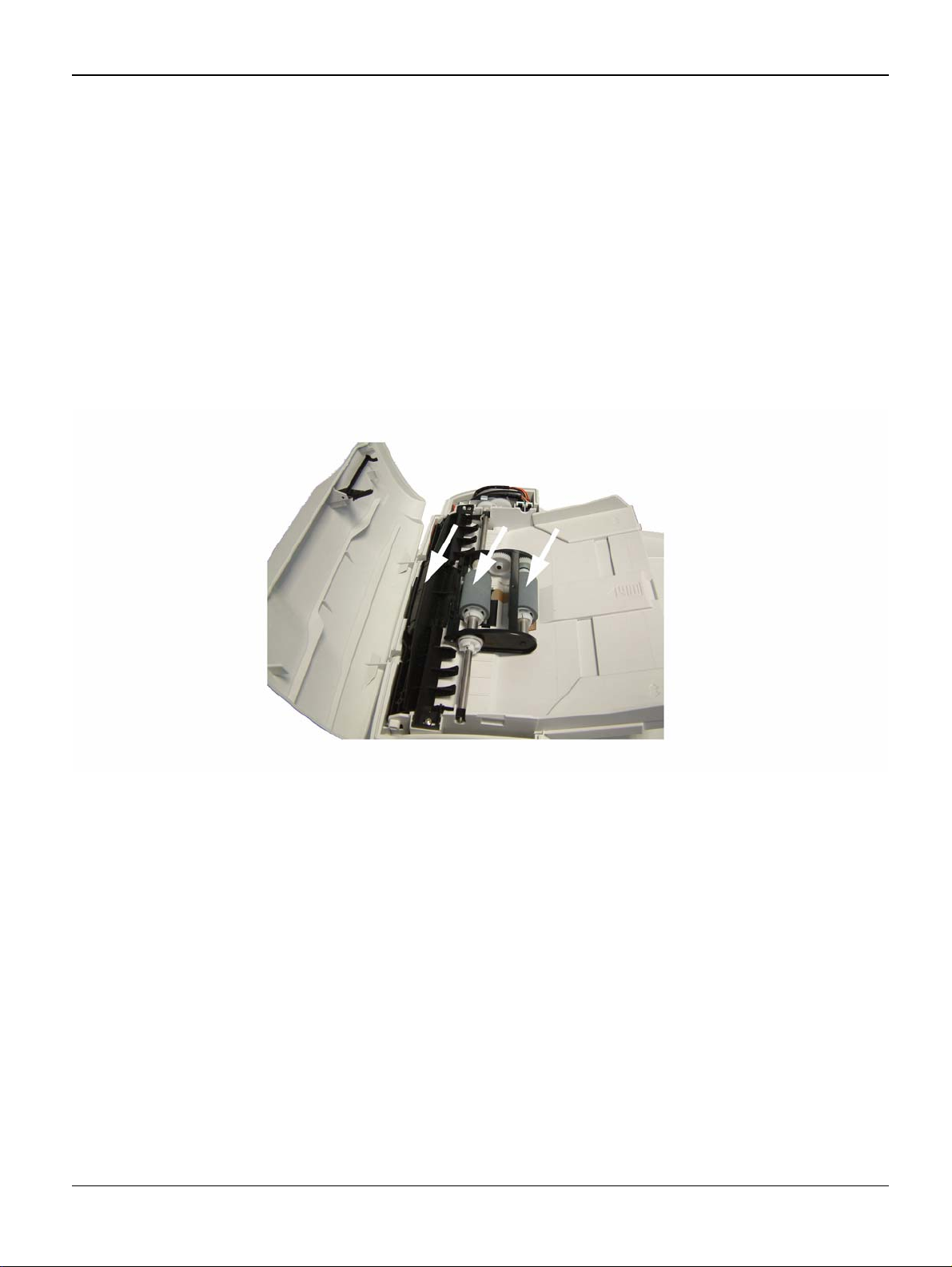
Paper Transport Rollers (3100 MFP/X only)
Figure 1
1. Set the On/Off switch to Off (position 0).
2. Open the ADF cover.
3. Clean the roller s of the docu ment feed er and feed sh afts, and al so the two i dler rol lers located
on the mobile part of the scanner, wit h a lint-free cloth moistened in isopropyl alcohol. To
clean them, rotate them in the same direction as during paper transport.
Recommended interval: from 2 to 6 months, depending on utilization.
1-4 04/08 Phaser 3100 MFP
Page 15

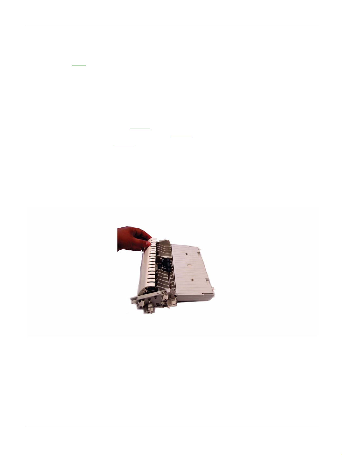
Paper Separator Module (3100 MFP/X only)
Service Call Procedures
Figure 2
1. Set the On/Off switch to Off (position 0).
2. Open the ADF scanner cover.
3. Disassemble the ADF feeder ( REP 4).
4. Wipe the elements of the paper separator module with a lint-free cloth soaked with isopropyl
alcohol. Recommended interval: from 2 to 6 months, depending on utilization.
CIS and Document Glass
1. Set the On/Off switch to Off (position 0).
2. Open the scanner cover.
3. Clean the CIS window with a lint-free cloth moistened with isopropyl alcohol or use antistatic
paper used for cleaning optic glass.
Recommended interval: depending on utilization; it is advisable to make a local copy to check if
the window is clean.
Control Panel Keys and Covers
Cleaning the Control Panel Keys
1. Set the On/off switch to Off (position 0).
2. Clean the top of the control panel and the keys wi th a lint-fr ee clot h mo i stened with isopropyl
alcohol or a spray-on cleaning product.
3. Leave the product on for a few seconds before wiping it off.
Recommended interval: to be defined depending on utilization.
Phaser 3100 MFP 04/08 1-5
Page 16

Service Call Procedures
Cleaning the Covers
It is advisable to clean all the covers during a maintenance visit.
1. Set the On/Off switch to Off (position 0).
2. Clean the external areas of the covers with a lint-free cloth moistened with isopropy l alcohol
or a spray-on cleaning prod uct.
3. Leave the product on for a few s ec onds before wiping it off.
1-6 04/08 Phaser 3100 MFP
Page 17

Service Call Procedures
SCP 3 Final Actions
After the machine has been re-assembled, perform the steps that follow:
1. Exercise the machine in all modes.
2. Make a proof copy or print of a customer document.
3. If any of the customers selections were changed, return them to the customers preferred settings.
4. Mark off any hardware/software options and modifications installed and/or enabled in the
Service Log, GP 19.
5. At the first service and at any subsequent service where changes are made or options are
added, print the configuration report and store it with the machine log book. Discard any previous versions of the configuration report.
6. Remove and destroy any copies of test patterns.
7. Complete the machine service log, refer to GP 19
8. Ensure the machine and service area are clean before leaving the customer premises.
9. Provide customer train ing if required.
Service Log.
Phaser 3100 MFP 04/08 1-7
Page 18

Service Call Procedures
This page is intentionally blank
1-8 04/08 Phaser 3100 MFP
Page 19

Status Indicator RAPs
2 Status Indicator RAPs
RAP 1 Error Codes ................................................................................................................... 2-3
RAP 2 Jam Detection ............................................................................................................... 2-6
Phaser 3100 MFP 04/08 2-1
Page 20

Status Indicator RAPs
This page is intentionally blank
2-2 04/08 Phaser 3100 MFP
Page 21

Status Indicator RAPs
RAP 1 Error Codes
Scanning and Communication Error Codes
The communication error codes appear in the logs (printed using key sequence 5 4) and in the
transmission reports.
General Codes
The following table presents and details for each error code displayed by the machine its cause
and when required the corrective action to perform.
Table 1:
Code Error Cause Action
01 Engaged or no fax tone This code appears after 6 failed attempts. Restart the transmission
at a later time.
03 Stopped by operator Communication stopped by the operator by
pressing the STOP key.
04 Programmed number invalid Invalid programmed single-key or quick-
dial number (Example: a delayed transmission has been programmed with a single
key and this key has been deleted).
05 Scanning fault An error has occurred at the location of the
document to be transmitted (Example: the
sheet is jammed).
06 Printer not available An error has occurred on the printer
(Example: out of paper, paper jam or cover
open). In the case of a reception, this incident code only appears if the
WITHOUT PAPER
W
ITHOUT PAPER.
07 Disconnect The communication has been cut (bad
connection).
08 Quality The document that you have transmitted
has not been received correctly.
parameter is set to
RECEPTION
Check the validity of the
programmed number
and/or the single-key
associated to the programmed number.
Check the ADF module.
Check the printer.
Check the called number.
Contact your correspondent to check
whether it i s nece ssar y to
retransmit the document:
the interference may
have occurred in an
unimportant area of the
document.
Phaser 3100 MFP 04/08 2-3
Page 22

Status Indicator RAPs
Table 1:
0A No document to recover You have attempted to recover a document
from a correspondent, but the latter has not
stored the document or the password that
was entered is wrong.
0B Wrong number of pages There is a difference between the number
of pages indicated when the document was
stored for transmission and the number of
pages actually transmitted.
0C Received document faulty. The document is too long to be received in
its entirety.
0D Document transmission fault Document reception error. Ask the correspondent to
13 Memory full The machine memory is full (there are too
many documents that have been received
but not yet printed, or waiting to be transmitted).
Contact your correspondent to check
whether the document to
recover has been stored
or to check the validity of
the password.
Check the number of
pages of the document.
Ask the correspondent to
check/reduce the length
of his document.
retransmit his document.
Print the received documents. Delete or transmit
in immediate mode the
documents waiting to be
transmitted.
14 Memory full Received document memory saturated. Print the received docu-
ments.
16 List number x not retransmitted Failure to retransmit a document via a
remote fax (the requested list of recipients
is not programmed on the remote fax).
19 Stopped by correspondent Communication stopped by your corre-
spondent (Example: a machine attempts to
recover a document from your machine,
and there is no document waiting for this
correspondent).
1A Disconnect Transmission has not started (the phone
line is too noisy).
Check that the list of
recipients is programmed
on the remote fax.
Check the quality of the
phone line or restart the
transmission at a later
time.
2-4 04/08 Phaser 3100 MFP
Page 23

Status Indicator RAPs
Table 1:
1B Document transmission fault Document transmission error. Transmission: restart the
transmission. Reception:
ask your correspondent
to retransmit the document.
Phaser 3100 MFP 04/08 2-5
Page 24

Status Indicator RAPs
RAP 2 Jam Detection
Jam 1. Paper jam at the paper cassette
When the registration sensor does not tur n on withi n 2.52 se conds aft er the pap er pick-up clutch
for the paper cassette turns on.
Jam 2. Paper did not pass the registration sensor
When the registration sensor does not turn off within the specif ie d ti me for passi n g each pape r
size (see below) + 3 seconds after the registration sensor turns on.
Table 2:
Paper Size A4SEF A5SEF A5LEF A6SEF B5SEF B6SEF Letter
SEF
Specified
Time
(msec)
2555 1807 1273 1273 2211 1566 2400 3059 1643
Legal
SEF
Envelope
(91x191mm)
Jam 3. Paper did not reach the fusing unit
When the paper exit sensor does not turn on within 1.94 seconds after the registration sensor
turns on.
Jam 4. Paper jam in the fusing exit area
When the paper exit sensor does not turn off within 2.99 seconds after the registration sensor
turns off.
Jam 5. Paper no feed jam in the bypass tray
When the registration sensor does not turn on within 1.72 seconds after the main motor starts.
2-6 04/08 Phaser 3100 MFP
Page 25

Image Quality
3 Image Quality
IQ 1 Checking the quality of Prints and Tuning the Scanner .................................................... 3-3
Phaser 3100 MFP 04/08 3-1
Page 26

Image Quality
This page is intentionally blank
3-2 04/08 Phaser 3100 MFP
Page 27

Image Quality
IQ 1 Checking the Quality of Prints and Calibrating the Scanner
To check or improve the qualit y of prints , you should first calibr ate the scann er. Follow thi s procedure:
1. Press enter * then A on the keyboard and confirm with OK. The machine reboots.
2. Start making copies of documen ts on the document gl ass and check the quality of the copies.
If the problem persists and if it is related to the scanner:
• Repeat the calibration procedure (step 1). If the problem persists and if it is related to the
printer (the scanner still provides unsatisfactory results):
1. Press then enter 56 on the keyboard. The machine prints the list of printer parameters.
2. Check the printer’s printing and copying parameters.
3. Check the print cartridge.
Phaser 3100 MFP 04/08 3-3
Page 28

Image Quality
This page is intentionally blank
3-4 04/08 Phaser 3100 MFP
Page 29

Repairs and Adjustments
4 Repairs and Adjustments
REP 1 Control Panel ....................................... ..... ..... ............................ .... ..... .......................... 4-3
REP 2 ADF Cover and Document Pad .................................................................................... 4-5
REP 3 Front Door and Side Cover .............................................. ..... ............................ ..... .... . 4-10
REP 4 Feeder Assembly ........................................................................................................ 4-13
REP 5 Retard Pad and Cork Pad ........................................................................................... 4-15
REP 6 ADF Document Feed Assembly .................................................................................. 4-17
REP 7 Upper Paper Guide Assembly .................................................................................... 4-20
REP 8 Motor Frame ............................................................................................................... 4-22
REP 9 ADF Feed Guide / Registration Roll / Paper Deflector ................................................ 4-25
REP 10 ADF Sliders and Antistatic Brush .............................................................................. 4-28
REP 11 CPU Module .............................................................................................................. 4-30
REP 12 Speaker ..................................................................................................................... 4-33
REP 13 Back Cover ............................................................................................................... 4-35
REP 14 Output Tray Assembly .............................................................................................. 4-37
REP 15 Machine Disassembly ............................................................................................... 4-39
REP 16 Scanner Assembly .................................................................................................... 4-40
REP 17 Power Supply Unit .................................................................................................... 4-43
REP 18 Scanner Frame ......................................................................................................... 4-44
REP 19 CIS ............................................................................................................................ 4-46
REP 20 CIS Ribbon Cable ..................................................................................................... 4-48
REP 21 CIS Support .............................................................................................................. 4-50
REP 22 Scanner Motor .......................................................................................................... 4-52
REP 23 Paper Tray Components ........................................................................................... 4-54
REP 24 Laser Unit .................................................................................................................. 4-58
REP 25 Fusing Unit ................................................................................................................ 4-61
REP 26 Paper Exit Assembly ................................................................................................. 4-63
REP 27 Fusing Lamp and Heat Roller ................................................................................... 4-65
REP 28 Pressure Roller ......................................................................................................... 4-70
REP 29 Thermistor ................................................................................................................. 4-73
REP 30 Thermostat ................................................................................................................ 4-74
REP 31 Heat Roller Stripper Fingers ..................................................................................... 4-76
REP 32 Paper Feed Roller ..................................................................................................... 4-78
REP 33 Registration Roller .................................................................................................... 4-81
REP 34 Transfer Roller .......................................................................................................... 4-84
REP 35 Fan Assembly ........................................................................................................... 4-86
REP 36 Main Motor ................................................................................................................ 4-87
REP 37 Discharge Lamp Assembly ....................................................................................... 4-89
REP 38 Scanner Cover and Document Pad .......................................................................... 4-91
Phaser 3100 MFP 04/08 4-1
Page 30

Repairs and Adjustments
This page is intentionally blank
4-2 04/08 Phaser 3100 MFP
Page 31

Repairs and Adjustments
REP 1 Control Panel
Parts List on: PL 1
WARNING
Switch off the electricity to the machine. Disconnect the power cord from the customer supply
while performing tasks that do not need electricity. Electricity can cause death or injury. Moving
parts can cause injury.
Preparation
• None.
Removal
1. Unlock the three clips of the front panel (A, B and C), Figure 1.
Figure 1 (3100 MFP/X shown, 3100 MFP/S similar)
2. Pull the panel forward to release it from the two bottom slots (D and E).
Phaser 3100 MFP 04/08 4-3
Page 32

Repairs and Adjustments
3. Disconnect the ribbon cable from the control panel board, Figure 2.
Figure 2
4. Remove the control panel.
Replacement
1. Replacement is the reverse of the removal pro cedure.
4-4 04/08 Phaser 3100 MFP
Page 33

Repairs and Adjustments
REP 2 ADF Cover and Document Pad
Parts List on: PL 7
WARNING
Switch off the electricity to the machine. Disconnect the power cord from the customer supply
while performing tasks that do not need electricity. Electricity can cause death or injury. Moving
parts can cause injury.
Preparation
• None.
Removal
Document Pad:
1. Raise the ADF.
2. Remove the document pad located on the underside of the ADF, Figure 1.
Figure 1
Phaser 3100 MFP 04/08 4-5
Page 34

Repairs and Adjustments
ADF Cover:
1. Close the ADF and open the ADF cover assembly, Figure 2.
Figure 2
2. Remove the ADF motor cover from its two slots using a flat screwdr iver then r emove the ADF
motor cover, Figure 3.
Figure 3
4-6 04/08 Phaser 3100 MFP
Page 35

3. Unscrew the mounting screw of the ground cable, Figure 4.
Repairs and Adjustments
Figure 4
4. Disconnect the ADF cover sen sor connector (A) and the paper sensor connector (B), Figure
5.
Figure 5
Phaser 3100 MFP 04/08 4-7
Page 36

Repairs and Adjustments
5. Open the ADF cover, unscrew the two mounting screws of the cable cover and remove the
cable cover, Figure 6.
Figure 6
6. Remove the ground cable, the ADF cover sensor connector and the paper sensor connector
from their cable guide then slide them out of the ADF cover, Figure 7.
Figure 7
4-8 04/08 Phaser 3100 MFP
Page 37

Repairs and Adjustments
7. Insert a flat screwdriver in each slot of the two ADF cover hinges, Figure 8.
Figure 8
8. Lift and remove the ADF cover, do not forget the mounting screws of the hinges, Figure 9.
Figure 9
Replacement
1. Replacement is the reverse of the removal pro cedure.
Phaser 3100 MFP 04/08 4-9
Page 38

Repairs and Adjustments
REP 3 Front Door and Side Cover
Parts List on: PL 2
WARNING
Switch off the electricity to the machine. Disconnect the power cord from the customer supply
while performing tasks that do not need electricity. Electricity can cause death or injury. Moving
parts can cause injury.
Preparation
• None.
Removal
Front Door:
1. Push the left and right side of the printer front door and simultaneously pull it forward.
2. Move the arms away from each other and remove the printer front door, Figure 1.
Figure 1
Side Covers:
1. Open the printer’s paper tray.
4-10 04/08 Phaser 3100 MFP
Page 39

Repairs and Adjustments
2. Unscrew the two mounting screws on the front and back of the side covers, front mounting
screw of the r i ght hand side c over, back moun ting screw of the right-hand si de cover, Figure
2.
Figure 2
3. Using a flat screwdriver, re lease the tabs under the covers from their slots, Figure 3.
Figure 3
Phaser 3100 MFP 04/08 4-11
Page 40

Repairs and Adjustments
4. Unclip the side covers from the top slots located at the back of the machine and pivot them
towards yourself to remove the m, Figure 4.
Figure 4
5. Remove the side covers.
Replacement
1. Replacement is the reverse of the removal pro cedure.
4-12 04/08 Phaser 3100 MFP
Page 41

Repairs and Adjustments
REP 4 Feeder Assembly
Parts List on: PL 8
WARNING
Switch off the electricity to the machine. Disconnect the power cord from the customer supply
while performing tasks that do not need electricity. Electricity can cause death or injury. Moving
parts can cause injury.
Preparation
• None.
Removal
1. Open the ADF cover, Figure 1.
Figure 1
2. Remove the ADF motor cover, refer to REP 2.
Phaser 3100 MFP 04/08 4-13
Page 42

Repairs and Adjustments
3. Lift the roller bearing, Figure 2.
Figure 2
4. Lift the roller bearing from the other end of the fee der, Figure 3.
Figure 3
5. Lift the feeder and remove the feeder.
Replacement
1. Replacement is the reverse of the removal pro cedure.
4-14 04/08 Phaser 3100 MFP
Page 43

Repairs and Adjustments
REP 5 Retard Pad and Cork Pad
Parts List on: PL 8
WARNING
Switch off the electricity to the machine. Disconnect the power cord from the customer supply
while performing tasks that do not need electricity. Electricity can cause death or injury. Moving
parts can cause injury.
Preparation
• Remove the feeder assembly, REP 4.
Removal
Rocking Plate:
1. Insert a screwdriver in the right slot as shown below and make a pivoting movement downwards without strain to remove the retard pad.
2. Repeat the previous step for the left slot of the retard pad, Figure 1.
Figure 1
3. Remove the feed roll assembly.
Phaser 3100 MFP 04/08 4-15
Page 44

Repairs and Adjustments
Cork Dad:
4. Insert a screwdriver in the right slot as shown below and make a pivoting movement downwards without strain to remove the cork pad, Figure 2.
Figure 2
Replacement
Cork Pad
1. Make sure that the slot of the cork on the paper input guide is clean.
2. Replacement is the reverse of the removal pro cedure.
Retard Pad Assembly:
1. Replacement is the reverse of the removal pro cedure.
4-16 04/08 Phaser 3100 MFP
Page 45

Repairs and Adjustments
REP 6 ADF Document Feed Assembly
Parts List on: PL 7
WARNING
Switch off the electricity to the machine. Disconnect the power cord from the customer supply
while performing tasks that do not need electricity. Electricity can cause death or injury. Moving
parts can cause injury.
Preparation
None.
Removal
1. Lift the ADF cover and unscrew the two mounting screws of the document feed assembly,
Figure 3.
Figure 3
Phaser 3100 MFP 04/08 4-17
Page 46

Repairs and Adjustments
2. Lift the document feed assembly and remove it from its slot without disassembling it, Figure
4.
Figure 4
3. Remove the m otor frame cable from its cable guide, Figure 5.
Figure 5
4-18 04/08 Phaser 3100 MFP
Page 47

Repairs and Adjustments
4. Disconnect the connector to the ADF cover and remove the assembly, Figure 6.
Figure 6
Replacement
1. Replacement is the reverse of the removal pro cedure.
Phaser 3100 MFP 04/08 4-19
Page 48

Repairs and Adjustments
REP 7 Upper Paper Guide Assembly
Parts List on: PL 8
WARNING
Switch off the electricity to the machine. Disconnect the power cord from the customer supply
while performing tasks that do not need electricity. Electricity can cause death or injury. Moving
parts can cause injury.
Preparation
• Remove the feeder assembly, REP 4.
Removal
1. Open the ADF cover.
2. Unscrew the two mounting screws of the paper guide assembly, Figure 1.
Figure 1
4-20 04/08 Phaser 3100 MFP
Page 49

3. Pull out the paper guide assembly, Figure 2.
Repairs and Adjustments
Figure 2
Replacement
1. Replacement is the reverse of the removal pro cedure.
Phaser 3100 MFP 04/08 4-21
Page 50

Repairs and Adjustments
REP 8 Motor Frame
Parts List on: PL 8
WARNING
Switch off the electricity to the machine. Disconnect the power cord from the customer supply
while performing tasks that do not need electricity. Electricity can cause death or injury. Moving
parts can cause injury.
Preparation
• Remove the feeder assembly, REP 4.
• Remove the document feed assembly, REP 6.
Removal
1. Unscrew the mounting screw of the motor frame, Figure 1.
Figure 1
4-22 04/08 Phaser 3100 MFP
Page 51

Repairs and Adjustments
2. Lift and remove the motor frame. Take note of the location of the teeth gears, then remove
them, Figure 2.
Figure 2
3. If required unscrew the two mounting screws of the motor and remove the motor, Figure 3.
Figure 3
Phaser 3100 MFP 04/08 4-23
Page 52

Repairs and Adjustments
Replacement
1. Replacement is the reverse of the removal pro cedure.
2. Position the teeth gears respecting their location identified during disassembly, Figure 4.
Figure 4
4-24 04/08 Phaser 3100 MFP
Page 53
Repairs and Adjustments
REP 9 ADF Feed Guide / Registration Roll / Paper Deflector
Parts List on: PL 9
WARNING
Switch off the electricity to the machine. Disconnect the power cord from the customer supply
while performing tasks that do not need electricity. Electricity can cause death or injury. Moving
parts can cause injury.
Preparation
• Remove the feeder assembly, REP 4.
• Remove the ADF document feed assembly, REP 6
• Remove the motor frame REP 8.
Removal
ADF Feed Guide
1. Turn the assembly upside down.
2. Lift the ADF feed guide to remove it from the ADF document feed assembly, Figure 1.
Figure 1
Phaser 3100 MFP 04/08 4-25
Page 54

Repairs and Adjustments
Paper Deflector
3. Turn the ADF assembly upside down.
4. Unclip the paper deflector and remove it.
Registration Roller
5. Turn the assembly upside down.
6. Turn each roller bearing of the registration roller, Figure 2.
Figure 2
7. Remove the E-clip, bearing, gear then the registration roller.
4-26 04/08 Phaser 3100 MFP
Page 55

Repairs and Adjustments
Replacement
ADF Feed Guide
1. Replacement is the reverse of the removal pro cedure.
Paper Deflector
2. Position the paper deflector on the registration roller and press to clip it in place, Figure 3.
Figure 3
Registration Roller
3. Replacement is the reverse of the removal pro cedure.
Phaser 3100 MFP 04/08 4-27
Page 56

Repairs and Adjustments
REP 10 ADF Sliders and Antistatic Brush
Parts List on: PL 8, PL 9
WARNING
Switch off the electricity to the machine. Disconnect the power cord from the customer supply
while performing tasks that do not need electricity. Electricity can cause death or injury. Moving
parts can cause injury.
Preparation
• Remove the feeder assembly, REP 4.
• Remove the ADF document feed assembly, REP 6
• Remove the motor frame REP 8.
Removal
1. Turn the assembly upside down.
2. Remove the 2 mounting screws of the lower cover and remove it, Figure 1.
Figure 1
4-28 04/08 Phaser 3100 MFP
Page 57

Repairs and Adjustments
3. Lift the rack gears and remove them from the input tray assembly, Figure 2.
Figure 2
4. Carefully remove the antistatic brush, Figure 3.
Figure 3
Replacement
1. Replacement is the reverse of the removal pro cedure.
2. Check that the slot of the antistatic brush is clean. Position the antistatic brush in its slot and
press on the lower part to make sure the adhesives are strongly fixed.
Phaser 3100 MFP 04/08 4-29
Page 58

Repairs and Adjustments
REP 11 CPU Module
Parts List on: PL 2
WARNING
Switch off the electricity to the machine. Disconnect the power cord from the customer supply
while performing tasks that do not need electricity. Electricity can cause death or injury. Moving
parts can cause injury.
Preparation
• Print the machine’s parameters (user, administrator and technical) and the activity counter
values in order to keep a record ( 5 6). You can al so stor e user par ame ter s and di r ecto ry
entries on a smart card ( * 6) and re stor e the m ( * 9) after the machine is serviced.
• Remove the printer front door assembly and the right side cover, REP 3
Removal
1. Unscrew the three mounting screws of the CPU board shield plate, Figure 1.
.
Figure 1
2. Pull the CPU bo ard shield plate forwards and remove it .
4-30 04/08 Phaser 3100 MFP
Page 59

Repairs and Adjustments
3. Unscrew the mounting screw of the CPU card ground connector and disconnect it, Figure 2.
Figure 2
4. Disconnect all connectors from the CPU board.
CAUTION
Note all connections for reassembly.
5. Unscrew the eight mounting screws and remove the CPU board, Figure 3.
Figure 3
Phaser 3100 MFP 04/08 4-31
Page 60

Repairs and Adjustments
Replacement
1. Replacement is the reverse of the removal pro cedure.
2. Connect all connectors to the CPU board, Figure 4.
3. Perform the scanner calibration ( 8 0).
Figure 4
4-32 04/08 Phaser 3100 MFP
Page 61

Repairs and Adjustments
REP 12 Speaker
Parts List on: PL 2
WARNING
Switch off the electricity to the machine. Disconnect the power cord from the customer supply
while performing tasks that do not need electricity. Electricity can cause death or injury. Moving
parts can cause injury.
Preparation
• Remove the printer front door assembly and the right side cover, REP 3.
• Remove the CPU shield plate, REP 11.
Removal
1. Disconnect the speaker conn ector from the CPU board.
CAUTION
Before removing the speaker harness from the ferrite tube make a note of the routing.
2. Remove the speaker connector from its ferrite tube and cable guide, Figure 1.
Figure 1
Phaser 3100 MFP 04/08 4-33
Page 62

Repairs and Adjustments
3. Press the top clip inwards until it unclips and pull out the speaker, Figure 2.
Figure 2
Replacement
1. Replacement is the reverse of the removal pro cedure.
4-34 04/08 Phaser 3100 MFP
Page 63

Repairs and Adjustments
REP 13 Back Cover
Parts List on: PL 3
WARNING
Switch off the electricity to the machine. Disconnect the power cord from the customer supply
while performing tasks that do not need electricity. Electricity can cause death or injury. Moving
parts can cause injury.
Preparation
• Remove the ADF cover, REP 2.
• Remove the printer front door and the side covers, REP 3.
• Remove the CPU shield plate, refer to REP 11.
• Remove the platen assemb ly, REP 16
Removal
1. Unscrew the two back mounting screws on the back cover (A and B), Figure 1.
.
Figure 1
Phaser 3100 MFP 04/08 4-35
Page 64

Repairs and Adjustments
2. Unscrew the two top mount ing screws on the back cover (C and D), Figure 2.
Figure 2
3. Pull the back cover and remove it.
Replacement
1. Replacement is the reverse of the removal pro cedure.
4-36 04/08 Phaser 3100 MFP
Page 65

Repairs and Adjustments
REP 14 Output Tray Assembly
Parts List on: PL 3
WARNING
Switch off the electricity to the machine. Disconnect the power cord from the customer supply
while performing tasks that do not need electricity. Electricity can cause death or injury. Moving
parts can cause injury.
Preparation
• Remove the ADF cover, REP 2.
• Remove the front door and the side covers, REP 3.
• Remove the CPU shield plate, REP 11.
• Remove the speaker, REP 12
• Remove the platen assemb ly, REP 16
• Remove the back cover, REP 13.
Removal
.
.
1. Unscrew the two mounting screws on the left and right side on the output tray assembly, Figure 1.
Figure 1
Phaser 3100 MFP 04/08 4-37
Page 66

Repairs and Adjustments
2. Lift and remove the out put tray assembly, Figure 2.
Figure 2
Replacement
1. Replacement is the reverse of the removal pro cedure.
4-38 04/08 Phaser 3100 MFP
Page 67

Repairs and Adjustments
REP 15 Machine Disassembly
Parts List on: PL 2
WARNING
Switch off the electricity to the machine. Disconnect the power cord from the customer supply
while performing tasks that do not need electricity. Electricity can cause death or injury. Moving
parts can cause injury.
Preparation
• None.
Removal
1. Stand in front of the machine.
2. Remove the control panel REP 1
3. Remove the ADF cover (REP 2
4. Remove the front door and the side covers (REP 3).
5. Remove the CPU module (REP 11) and the speaker (REP 12).
6. Remove the platen assembly (REP 16).
7. Remove the back cover (REP 13) and the output tray assembly (REP 14).
.
) or the platen cover (REP 38).
Replacement
1. Replacement is the reverse of the removal pro cedure.
Phaser 3100 MFP 04/08 4-39
Page 68

Repairs and Adjustments
REP 16 Scanner Assembly
Parts List on: PL 2
WARNING
Switch off the electricity to the machine. Disconnect the power cord from the customer supply
while performing tasks that do not need electricity. Electricity can cause death or injury. Moving
parts can cause injury.
Preparation
• Print the machine’s parameters (user, administrator and technical) and the activity counter
values in order to keep a record ( 5 6). You can al so stor e user par ame ter s and di r ecto ry
entries on a smart card ( * 6) and restore them ( * 9) after the machine is serviced.
• Remove the printer front door and the side covers, REP 3
• Remove the CPU shield plate, REP 11
.
Removal
1. Disconnect the scanner connector from the CPU board and remove it from its ferrite tube and
cable guide.
CAUTION
Before removing the ribbon connections make a note of the correct connection positions.
2. Disconnect the front panel ribbo n cable and th e CIS ribb on cable fr om the CPU bo ard, Fig ure
1.
.
Panel ribbon connection CIS ribbon connection
Figure 1
4-40 04/08 Phaser 3100 MFP
Page 69

Repairs and Adjustments
3. Remove the front panel and CIS ribbon cables from their cable guide, Figure 2.
Figure 2
4. Use a flat head screwdriver to unhook, then remove the scanner assembly, Figur e 3.
Figure 3
Phaser 3100 MFP 04/08 4-41
Page 70

Repairs and Adjustments
5. Lift, then remove the platen assembly, Figure 4.
Figure 4
Replacement
1. Replacement is the reverse of the removal pro cedure.
2. Perform the scanner calibration ( 8 0).
4-42 04/08 Phaser 3100 MFP
Page 71

Repairs and Adjustments
REP 17 Power Supply Unit
Parts List on: PL 13
WARNING
Switch off the electricity to the machine. Disconnect the power cord from the customer supply
while performing tasks that do not need electricity. Electricity can cause death or injury. Moving
parts can cause injury.
Preparation
• Remove the print cartridge.
• Remove the paper tray.
• Remove the output tray assembly, R EP 14
• Remove the right and left shield, refer to REP 36
Removal
1. Remove the power supply unit, Figure 1.
1
Remove 4 connectors,
circled in blue
Figure 1
Replacement
1. Replacement is the reverse of the removal pro cedure.
2
Remove 9 screws to
remove the power
supply unit
Phaser 3100 MFP 04/08 4-43
Page 72

Repairs and Adjustments
REP 18 Scanner Frame
Parts List on: PL 5
WARNING
Switch off the electricity to the machine. Disconnect the power cord from the customer supply
while performing tasks that do not need electricity. Electricity can cause death or injury. Moving
parts can cause injury.
Preparation
• Remove the ADF cover, REP 2, or the platen cover, REP 38.
• Remove the front door and the side covers, REP 3.
• Remove the CPU shield plate, REP 11.
• Remove the platen assemb ly, REP 16
Removal
1. Remove the two mounting screws on the frame (A and B) and turn the cover upside down,
Figure 1.
.
Figure 1
4-44 04/08 Phaser 3100 MFP
Page 73

Repairs and Adjustments
2. Unscrew the seven mou nting scr ews at the back of t he fr ame and t urn it u pside down, Figu re
2.
Figure 2
3. Lift the front part o f the scanner frame and remove it, Figure 3.
Figure 3
Replacement
1. Replacement is the reverse of the removal pro cedure.
Phaser 3100 MFP 04/08 4-45
Page 74

Repairs and Adjustments
REP 19 CIS
Parts List on: PL 5
WARNING
Switch off the electricity to the machine. Disconnect the power cord from the customer supply
while performing tasks that do not need electricity. Electricity can cause death or injury. Moving
parts can cause injury.
Preparation
• Remove the ADF cover, REP 2.
• Remove the printer front door and the side covers, REP 3.
• Remove the CPU armour plate, REP 11.
• Remove the platen assemb ly, REP 16
Removal
1. Lift the CIS backwards, Figure 1.
.
Figure 1
4-46 04/08 Phaser 3100 MFP
Page 75

Repairs and Adjustments
2. Disconnect the CIS ribbon cable and remove it from its two side slots, Figure 2.
CAUTION
Keep the CIS support springs and slides.
Figure 2
3. Remove the CIS.
Replacement
1. Replacement is the reverse of the removal pro cedure.
Phaser 3100 MFP 04/08 4-47
Page 76

Repairs and Adjustments
REP 20 CIS Ribbon Cable
Parts List on: PL 6
WARNING
Switch off the electricity to the machine. Disconnect the power cord from the customer supply
while performing tasks that do not need electricity. Electricity can cause death or injury. Moving
parts can cause injury.
Preparation
• Remove the ADF cover, REP 2.
• Remove the front door and the side covers, REP 3.
• Remove the CPU shield plate, REP 11.
• Remove the platen assemb ly, REP 16
Removal
1. Unfold the end of the CIS ribbon cable and remove it from its slot, Figure 1.
.
Figure 1
2. Slide the CIS ribbon cable out of its ferrite tube which is fixed to the CIS panel and remove it
from the scanner.
3. Remove the CIS ri bbon cable f rom its cabl e guid es lo cated a bove a nd be low th e scann er b ottom then slide it to remove it from the scanner bottom.
CAUTION
Note the cable guide positio n for rea ssem bly.
4. Remove the CIS ribbon cable.
4-48 04/08 Phaser 3100 MFP
Page 77

Replacement
1. Replacement is the reverse of the removal pro cedure.
Repairs and Adjustments
Phaser 3100 MFP 04/08 4-49
Page 78

Repairs and Adjustments
REP 21 CIS Support
Parts List on: PL 6
WARNING
Switch off the electricity to the machine. Disconnect the power cord from the customer supply
while performing tasks that do not need electricity. Electricity can cause death or injury. Moving
parts can cause injury.
Preparation
• Remove the ADF cover, REP 2.
• Remove the front door and the side covers, REP 3.
• Remove the CPU shield plate, REP 11.
• Remove the platen assemb ly, REP 16
Removal
1. Lift the CIS drive pulley and the drive to remove the CIS drive pulley from its slot, Figure 1.
.
Figure 1
4-50 04/08 Phaser 3100 MFP
Page 79

2. Remove the belt from the drive pulley, Figure 2.
Repairs and Adjustments
Figure 2
3. Lift then remove the CIS panel.
Replacement
1. Replacement is the reverse of the removal pro cedure.
Phaser 3100 MFP 04/08 4-51
Page 80

Repairs and Adjustments
REP 22 Scanner Motor
Parts List on: PL 5
WARNING
Switch off the electricity to the machine. Disconnect the power cord from the customer supply
while performing tasks that do not need electricity. Electricity can cause death or injury. Moving
parts can cause injury.
Preparation
• Remove the ADF cover, REP 2.
• Remove the front door and the side covers, REP 3.
• Remove the CPU shield plate, REP 11.
• Remove the platen assemb ly, REP 16
Removal
1. Unscrew the two mounting screws of the scanner motor (A and B), Figure 1.
.
Figure 1
2. Remove the end of the scanner motor connector from its ferrite tube.
4-52 04/08 Phaser 3100 MFP
Page 81

3. Remove the CIS motor connector from its ca ble guide, Figur e 2.
Repairs and Adjustments
Figure 2
4. Remove the scanner motor.
Replacement
1. Replacement is the reverse of the removal pro cedure.
Phaser 3100 MFP 04/08 4-53
Page 82

Repairs and Adjustments
REP 23 Paper Tray Components
Parts List on: PL 10
WARNING
Switch off the electricity to the machine. Disconnect the power cord from the customer supply
while performing tasks that do not need electricity. Electricity can cause death or injury. Moving
parts can cause injury.
Preparation
None.
Removal
1. Remove the paper tray, Figure 1.
Figure 1
4-54 04/08 Phaser 3100 MFP
Page 83

Pinion Gear
2. Remove the pinion gear, Fig ure 2.
Repairs and Adjustments
Figure 2
Phaser 3100 MFP 04/08 4-55
Page 84

Repairs and Adjustments
3. Unhook and lift the bottom plate, Figure 3.
Figure 3
4. Unhook the left pinion gear. Repeat with the ri ght pinion gear .
Bottom Plate
5. Unhook the bottom plate from the pivots pins at both sides of the cassette, Figure 3.
4-56 04/08 Phaser 3100 MFP
Page 85

Friction Pad
6. Release 2 ho oks from below, Figure 4.
CAUTION
When releasing the hooks take care not to lose the spring.
Repairs and Adjustments
Figure 4
Replacement
1. Replacement is the reverse of the removal pro cedure.
Phaser 3100 MFP 04/08 4-57
Page 86

Repairs and Adjustments
REP 24 Laser Unit
Parts List on: PL 13
WARNING
Switch off the electricity to the machine. Disconnect the power cord from the customer supply
while performing tasks that do not need electricity. Electricity can cause death or injury. Moving
parts can cause injury.
WARNING
Avoid exposure to laser beam. Invisible laser radiation.
Preparation
1. Remove the output tray assembly, REP 14
4-58 04/08 Phaser 3100 MFP
Page 87

Removal
2. Remove the laser unit, Figure 1.
Repairs and Adjustments
1
Disconnect the laser
diode harness
2
Disconnect the polygon
mirror motor harness
Figure 1
3
Remove 3 scr ews (circled)
to remove the laser unit
Phaser 3100 MFP 04/08 4-59
Page 88

Repairs and Adjustments
Replacement
1. Replacement is the reverse of the removal pro cedure.
2. When reassembling, ensure to set the positioning pin in the hole, Figure 2.
Positioning pin
Figure 2
4-60 04/08 Phaser 3100 MFP
Page 89

Repairs and Adjustments
REP 25 Fusing Unit
Parts List on: PL 12
WARNING
Switch off the electricity to the machine. Disconnect the power cord from the customer supply
while performing tasks that do not need electricity. Electricity can cause death or injury. Moving
parts can cause injury.
WARNING
Do not touch the fuser while it is hot.
Preparation
• Remove the output tray assembly, R EP 14
Removal
1. Remove the fusing unit, Figure 1.
4
Remove 4 screws
(circled in blue) to
remove the fusing
unit
2
Disconnect the paper
exit sensor harness
1
Disconnect the
thermistor harness
3
Disconnect the fusing
lamp harness
Figure 1
Phaser 3100 MFP 04/08 4-61
Page 90

Repairs and Adjustments
Replacement
1. Replacement is the reverse of the removal pro cedure.
4-62 04/08 Phaser 3100 MFP
Page 91

Repairs and Adjustments
REP 26 Paper Exit Assembly
Parts List on: PL 12
WARNING
Switch off the electricity to the machine. Disconnect the power cord from the customer supply
while performing tasks that do not need electricity. Electricity can cause death or injury. Moving
parts can cause injury.
Preparation
• Remove the fuser, REP 25
Removal
1. Remove the end plate, Figure 1.
1
Remove 1 screw
Figure 1
Phaser 3100 MFP 04/08 4-63
Page 92

Repairs and Adjustments
2. Remove 2 screws to remove the paper exit assembly, Figure 2 and Figure 3.
1
Remove 2 screws
Figure 2
Figure 3
Replacement
1. Replacement is the reverse of the removal pro cedure.
4-64 04/08 Phaser 3100 MFP
Page 93

Repairs and Adjustments
REP 27 Fusing Lamp and Heat Roller
Parts List on: PL 12
WARNING
Switch off the electricity to the machine. Disconnect the power cord from the customer supply
while performing tasks that do not need electricity. Electricity can cause death or injury. Moving
parts can cause injury.
WARNING
Do not touch the fuser while it is hot.
Preparation
• Remove the paper exit assembly, REP 26.
• Remove the fuser, REP 25
Phaser 3100 MFP 04/08 4-65
Page 94

Repairs and Adjustments
Removal
Fusing Lamp
1. Release the fusing lamp, Figu re 1.
CAUTION
Do not touch the surface of the fusing la mp with bare ha nds. Take care when removi ng the la mp,
it can break if not handled with care.
1
Remove 2 screws,
1 at each end of the fusing lamp
Figure 1
4-66 04/08 Phaser 3100 MFP
Page 95

2. Remove the fusing lamp from the fuser, Figure 2.
1
Carefully remove the fusing
lamp by withdrawing it from
the fuser
Repairs and Adjustments
Hot Roller
3. Disconnect the electrode , Figure 3.
1
Disconnect the electrode
Figure 2
Figure 3
Phaser 3100 MFP 04/08 4-67
Page 96

Repairs and Adjustments
4. Pull the heat roller out of the fuser unit, Figure 4.
CAUTION
Do not touch the surface of the heat roller with bare hands.
Figure 4
4-68 04/08 Phaser 3100 MFP
Page 97

Repairs and Adjustments
Replacement
1. Replacement is the reverse of the removal pro cedure.
CAUTION
When re-assembling, be careful not to damage the stripper fingers.
2. When reassembling, be careful to set the fusing lamp on the frame first, then set the terminals, Figure 5.
Figure 5
Phaser 3100 MFP 04/08 4-69
Page 98

Repairs and Adjustments
REP 28 Pressure Roller
Parts List on: PL 12
WARNING
Switch off the electricity to the machine. Disconnect the power cord from the customer supply
while performing tasks that do not need electricity. Electricity can cause death or injury. Moving
parts can cause injury.
WARNING
Do not touch the fuser while it is hot.
Preparation
• Remove the paper exit assembly, REP 26.
• Remove the fusing lamp and hot roller, REP 27.
4-70 04/08 Phaser 3100 MFP
Page 99

Removal
1. Remove the pressure roller, Figure 1.
CAUTION
Note the position of the bushing and spring at each end of the roller.
Pressure roller
Repairs and Adjustments
Bushing and spri ng at ea ch side
Figure 1
Phaser 3100 MFP 04/08 4-71
Page 100

Repairs and Adjustments
Replacement
1. Replacement is the reverse of the removal pro cedure.
2. When re-assembling, be careful to set the bushing and spring in the correct position, Figure
2.
Figure 2
4-72 04/08 Phaser 3100 MFP
 Loading...