

Page 1

Xerox® Phaser® 3052/3260
Service Manual
702P02830
June 2014
Initial Issue
Page 2

Page 3

Xerox® Phaser® 3052/3260 Service Manual
Service Documentation
Xerox® Phaser® 3052/3260 Service Manual
702P02830
June 2014
Prepared by:
Content Development and Language Services - North America
800 Phillips Road - Building 218-01A
Webster, New York 14580-9791
ISO9001 and ISO27001 Certified
©2014 Xerox Corporation. All rights reserved. Xerox®, Xerox and Design®, and Xerox® are
trademarks of Xerox Corporation in the US and/or other countries.
Printed in the United States of America.
***Xerox Private Data***
All service documentation is supplied to Xerox external customers for informational purposes
only. Xerox service documentation is intended for use by certified, product-trained service personnel only. Xerox does not warrant or represent that it will notify or provide to such customer
any future change to this documentation. Customer performed service of equipment, or m odules, components, or parts of such equipment may affect whether Xerox is responsible to fix
machine defects under the warranty offered by Xerox with respect to such equipment. You
should consult the applicable warranty for its terms regarding customer or third-party provided
service.
WARNING
This equipment generates, uses and can radiate radio frequency energy, and if not
installed and used in accordance with the instructions documentation, may cause interference to radio communications. It has been tested and found to comply with the limits
for a Class A computing device pursuant to subpart J of part 15 of FCC rules, which are
designed to provide reasonable protection against such interference when operated in
a commercial environment. Operation of this equipmen t in a residential area is likely to
cause interference in which case the u ser, at his own expense, will be required to correct the interference.
DANGER: Cet équipement génère, utilise et peut émettre des fréquences radio, et, s'il
n'est pas installé et utilisé selon les recommandations du manuel d'instructions, peut
causer des interférences aux communications radio. Il a été testé et jugé conforme aux
limites des systèmes de catégorie A, conformément à la partie 15 de l'alinéa J des règlements FCC, établis pour protéger contre de telles interférences pendant le fonctionnement en milieu commercial. Dans une zone résidentielle, il peut causer des
interférences; dans ce cas, l'utilisateur devra corriger le problème à ses propres frais.
While Xerox has tried to make the documentation accurate, Xerox will have no liability arising
out of any inaccuracies or omissions.
June 2014
Xerox® Phaser® 3052/3260
1
Page 4

June 2014
2
Xerox® Phaser® 3052/3260
Page 5

About This Documentation.............................................................................................. iii
How to Use this Manual .................................................................................................. iv
Service Safety Summary............................................................... .................................. v
Reference Symbology..................................................................................................... vi
Voltage Specifications........................................................... .... .. .. .... .. .. ....... .. .... .. .. .... ..... vii
Health and Safety Incident Reporting ............................................................................. viii
Regulatory Specifications............................................................................... .. .. .... .. .. ..... ix
Translation of Warnings .................................................................................................. x
Tag Usage................................................... ........................................ ............................xi
Phaser® 3052/3260 Overview ...................................................... .... .. ......... .... .... .. .... ..... xii
Introduction
Xerox® Phaser® 3052/3260 Service Manual
June 2014
i
Introduction
Page 6

Introduction
June 2014
ii
Xerox® Phaser® 3052/3260 Service Manual
Page 7

About This Documentation
Introduction
The Xerox® Phaser® 3052/3260 Service Manual is part of the multinational documentation for
the Xerox® Phaser® 3052/3260 Printer. It is structured in standard Xerox service documentation format. This manual is the primary document used for diagnosing, repairing, maintaining,
and troubleshooting these systems. The Service Manual is the controlling publication for a service call. Information about using this document is found in the Introduction s ection . To ensure
understanding of this product, complete the Xerox Service Training Program for this particular
printer.
Organization
The Xerox® Phaser® 3052/3260 Printer Service M anual is organized and defined within the
following sections:
Section 1 Service Call Procedures
This section contains procedures that determine what actions are to be taken during a
service call on the machine and in what sequence they are to be completed. This is the
entry level for all service calls.
Section 2 Status Indicator RAPs
This section contains the diagnostic aids for troubleshooting the Fault Code and non-Fault
Code related faults (with the exception of image quality problems).
Section 3 Image Quality Repair Analysis Procedures
This section contains the diagnostic aids for troubleshooting any image quality problems,
as well as image quality specifications and image defect samples.
Section 4 Repairs and Adjustments
This section contains the Adjustment and Repair procedures.
Section 5 Parts List
This section consists of a series of illustrations and an associated parts listing. Any part
that is spared or any part that must be removed to access a spared part is illustrated.
Common hardware is shown as a letter callout.
Section 6 General Procedures and Information
This section contains general information, change tag information, and general procedures.
Section 7 Wiring Data
This section contains Block Schematic Diagrams (BSDs), Plug/Jack locations, Voltage
Specifications, and I/O Module locations and information.
Component Names
Names of parts that appear in the procedures may not be exactly the same as the names that
appear on the part or listed in the Parts List. For example: a part called the Registration
Assembly may appear on the Parts List as Assembly, REGI.
Repairs include procedures for removal and replacement of parts which have the following
special conditions:
• When there is a personnel or machine safety issue.
• When removal or replacement cannot be determined from the exploded view of the Parts
List.
• When there is a cleaning or a lubricating activity associated with the procedure.
• When the part requires an adjustment after replacement.
• When a special tool is required for removal or replacement.
Use the repair procedures for the correct order of removal and replacement, for warnings, cautions, and notes.
Adjustments include procedures for adjusting the parts that must be within specification for the
correct operation of the system.
Use the adjustment procedures for the correct sequence of operation for specifications, warnings, cautions and notes.
June 2014
Xerox® Phaser® 3052/3260 Service Manual
Introduction
iii
About This Documentation
Page 8

How to Use this Manual
Always start with Service Call Procedures, Section 1. Per form Initial Actions and verify the
problem, then follow the directions given.
How to Differentiate Between Machine Variants
The machine configuration will be identified in this manual by the configuration identifiers
3052NI, 3260DI, 3260DNI and 3260DN.
The Phaser® 3052/3260 is Blue Angel certified with software configuration for up to 29 ppm
capability. Refer to the User Guide, Parts List and Procedures for information specific to printer
configuration.
When a procedure, parts list description or other reference is unique amongst different configurations of the machine, the appropriate configuration designator is indicated. Any artwork is
also specific.
NOTE: This manual services all configurations of the machine. Ignore references to options
not installed on the machine.
Warnings, Cautions and Notes
WARNING
A warning is used whenever an operating or maintena nce procedure, practice, condition or statement, if not strictly observed, could result in personal injury.
A translated version of all warnings is in Translation of Warnings.
CAUTION
A caution is used whenever an operation or maintenance procedure, practice, condition or
statement, if not strictly observed, could result in damage to the equipment.
NOTE: A note is used where it is essential to highlight a procedure, practice, condition or statement.
Introduction
June 2014
iv
Xerox® Phaser® 3052/3260 Service Manual
Page 9

Service Safety Summary
General Guidelines
For qualified service personnel only: Refer also to Electrical Safety.
Avoid servicing alone: Do not perform internal service or adjustment of this product unless
another person capable of rendering first aid or resuscitation is present.
Use care when servicing with power applied: Dangerous voltages may exist at several points in
this product. To avoid personal injury, do not touch exposed connections and components
while power is on. Disconnect power before removing the power supply shield or replacing
components.
Do not wear jewelry: Remove jewelry prior to servicing. Rings, necklaces and other metallic
objects could come into contact with dangerous voltages and currents.
Electrical Safety
• Use the Power Cord supplied with the printer.
• Plug the Power Cord directly into a properly grounded electrical outlet.
• Do not use a ground adapter plug to connect the printer to an electrical outlet that does
not have a ground connection terminal.
• Do not use an extension cord or power strip.
• Do not place the system in an area where people might step on the power cord.
• Do not place objects on the power cord.
• Do not block the ventilation openings. These openings are provided to prevent overheat ing of the printer.
• Do not drop paper clips or staples into the printer.
Operational Safety
The printer and supplies were designed and tested to meet strict safety requirements. These
include safety agency examination, approval, and compliance with established environmental
standards.
Pay attention to these safety guidelines to ensure the continued, safe operation of the printer.
• Use the supplies specifically designed for your system. The use of unsuitable materials
may cause poor performance and a possible safety hazard.
• Follow all warnings and instructions marked on, or supplied with, the system, options and
supplies.
NOTE: The Total Satisfaction Guarantee is available in the United States and Canada. Coverage may vary outside these areas; please contact your local representative for details.
Warning Labels
Read and obey all posted warning labels. Throughout the printer, warning labels are displayed
on potentially dangerous components. As you service the printer, check to make certain that all
warning labels remain in place.
Safety Interlocks
Make sure all covers are in place and all interlock s witches are functioning correc tly after you
have completed a printer service call. If you bypass an interlock switch during a service call,
use extreme caution when working on or around the printer.
Electrostatic Discharge (ESD) Field Service Kit
The purpose of the ESD Protection Program is to preserve the inherent reliability and quality of
electronic components that are handled by the Field Service Personnel. This program has
been implemented as a direct result of advances in microcircuitry technology, as well as a new
acknowledgment of the magnitude of the ESD problem in the electronics industry today.
This program will reduce Field Service costs that are cha rged to PWB failures. Ninety percent
of all PWB failures that are ESD related do not occur immediately. Using the ESD Field Service
Kit will eliminate these delayed failures and intermittent problems caused by ESD. This will
improve product reliability and reduce callbacks.
The ESD Field Service Kit should be used whenever Printed Wiring Boards or ES D sensitive
components are being handled. This includes activities like replacing or re-seating of circuit
boards or connectors. The kit should also be used in order to prevent additional damage when
circuit boards are returned for repair.
The instructions for using the ESD Field Service Kit can be found in GP 7 in the General Procedures section of the Service Documentation.
Product Safety Certification
This product is certified by various NRTLs/NCBs to the safety standards listed below:
UL60950-1/CSA22.2, No. 60950-1 (USA/Canada)
IEC60950-1 (CB Scheme)
Maintenance Safety
• Do not attempt any maintenance procedure that is not specifically described in the doc umentation supplied with the printer.
• Do not use aerosol cleaners. The use of supplies that are not approved may cause poor
performance and could create a hazardous condition.
• Do not burn any consumables or routine maintenance items. For inform ation on Xerox
supplies recycling programs, go to www.xerox.com/gwa.
June 2014
Xerox® Phaser® 3052/3260 Service Manual
Introduction
v
Service Safety Summary
Page 10
Reference Symbology
Safety Symbols and Terminology
The following are examples of the terminology and symbols that are used in this documentation for an Electrostatic Device Caution, Laser Warning, and general Warnings, Cautions, or
Notes.
WARNING
Improper operation ma y result in injury to a person.
CAUTION
Improper operation may result in machine damage.
ESD
Certain components in this product are susceptible to damage from Electrostatic Discharge.
Observe all ESD procedures to avoid component damage.
The following reference symbols are used throughout the Xerox® Phaser® 3052/3260 Service
Manual.
1. Flag
• This symbol indicates a reference point into a circuit diagram from a RAP.
Laser
Indicates that Laser safety precautions must be used.
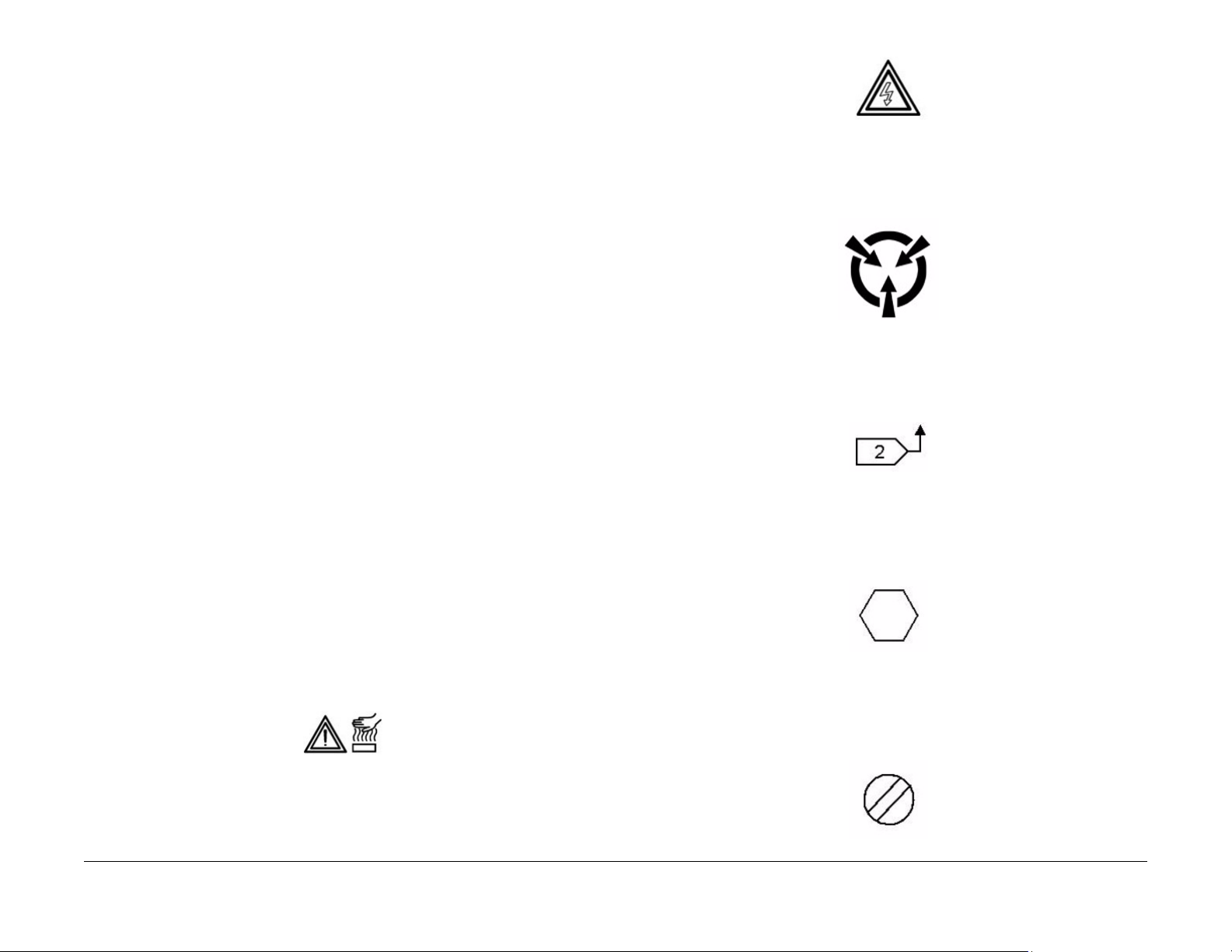
Hot Surface
Indicates that a surface can be hot. Use caution when reaching in the machine to avoid touching the hot surface.
Electrical Current
Danger label indicates where electrical currents travel when the machine is closed and operating. Use caution when reaching in the machine.
Introduction
June 2014
2. Note
• This symbol is used to refer to notes that are found on the same page of a circuit dia-
• Hints or other information that may assist the user.
3. Parts List
• This symbol, refers to the Parts List exploded view page where the part can be
4. Adjustment
• This symbol refers to an adjustment procedure in the Repair/Adjustments section.
vi
gram. A note is used whenever it is necessary to highlight an operating or maintenance procedure, a practice, condition, or statement.
found.
Xerox® Phaser® 3052/3260 Service Manual
Page 11
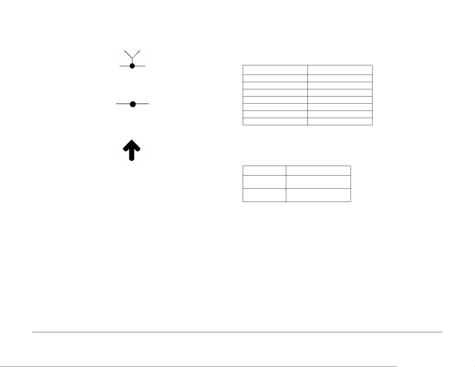
5. Test Point, Test Hole, Test Stake
• This symbol is used to indicate that a test point, test hole, or test stake is available
for accessing the signal line. The prefix indicates whether the acces s is a test point
(TP), test hole (TH), or test stake (TS).
6. Commoning Point
• This symbol is used to refer to a location in the machine wiring where more than two
wires a connected together at a single point.
7. Arrow
• This symbol points to the location to install, gain access to, or to release a compo-
nent.
Voltage Specific ations
AC and DC Voltages
Measurements of DC voltage must be made with reference to the specified DC Common,
unless some other point is referenced in a diagnostic procedure. All measurements of AC voltage should be made with respect to the adjacent return or ACN wire (Table 1).
Table 1 Voltage Measurement and Specifications
VOLTAGE SPECIFICATION
110 to120 VAC 60Hz 100 to 132 VAC
Neutral to Ground VAC 0 VAC (+/- 5VAC)
+5 VDC +5.05 VDC TO +5.25 VDC
+12 VDC +11.4 VDC TO +12.6 VDC
-12 VDC -11. 4 VDC TO -12.6 VDC
+24 VDC +22.8VDC TO +25.2 VDC
+36 VDC +34.2 VDC TO +37.8 VDC
Logic Voltage Levels
Measurements of logic levels must be made with reference to the specified DC Common,
unless some other point is referenced in a diagnostic procedure (Table 2)
Table 2 Logic Levels
VOLTAGE H/L SPECIFICATIONS
+5 VDC H= +3.00 TO +5.25 VDC, L=
0.0 TO 0.8 VDC
+24 VDC H= +23.37 TO +27.06 VDC,
L= 0.0 TO 0.8 VDC
Xerox® Phaser® 3052/3260 Service Manual
DC Voltage Measurements in RAPs
The RAPs have been designed so that when it is required to use the DMM to measure a DC
voltage, the first test point listed is the location for the red (+) meter lead and the second test
point is the location for the black meter lead. For example, the following statement may be
found in a RAP:
There is +5 VDC from TP7 to TP68.
In this example, the red meter lead would be placed on TP7 and the black meter lead on TP68.
Another example of a statement found in a RAP might be:
There is -15 VDC from TP21 to TP33.
In this example, the red meter lead would be placed on TP21 and the black meter lead would
be placed on TP33.
If a second test point is not given, it is assumed that the black meter lead may be attached to
the copier frame.
June 2014
vii
Voltage Specifications
Introduction
Page 12

Health and Safety Incident Reporting
I. Summary
This section defines requirements for notification of health and safety incidents involving Xerox
products (equipment and materials) at customer locations.
II. Scope
Xerox Corporation and subsidiaries worldwide.
III. Objective
To enable prompt resolution of health and safety incidents involving Xerox pro ducts and to
ensure Xerox regulatory compliance.
IV. Definitions
Incident:
An event or condition occurring in a customer accoun t that has resulted in injury, illness or
property damage. Examples of incidents include machine fires, smoke g eneration, physical
injury to an operator or service representative. Alleged events and product conditions are
included in this definition.
V. Requirements
Initial Report:
1. Xerox organizations shall establish a process for individuals to report product incidents to
Xerox Environment Health & Safety within 24 hours of becoming aware of the event.
2. The information to be provided at the time of reporting is contained in Appendix A (Health
and Safety Incident Report involving a Xerox product).
3. The initial notification may be made by any of the following methods:
• For incidents in North America and Developing Markets West (Brazil, Mexico, Latin
American North and Latin American South):
– Phone* Xerox EH&S at: 1-800-828-6571.
– Electronic mail Xerox EH&S at: USA.XEROX.EHS@xerox.com.
– Fax Xerox EH&S at: 1-585-216-8817 [intelnet 8*219-68817].
• For incidents in Europe and Developing Markets East (Middle East, Africa, India,
China and Hong Kong):
– Phone* Xerox EH&S at: +44 (0) 1707 353434 [intelnet 8*668 3434]
– Electronic mail Xerox EH&S at: EH&S-Europe@xerox.com
– Fax Xerox EH&S at: +44 (0) 1707 353914 [intelnet 8*668 3914]
*Initial notification made by phone must be followed within 24 hours by a completed incident report and sent to the indicated electronic mail address or fax number.
NOTE: If sending a fax, please also send the original via internal mail.
Responsibilities for resolution:
1. Business Groups/Product Design Teams responsible for the product involved in the incident shall:
a. Manage field bulletins, customer correspondenc e, product recalls, safety retrofits.
b. Fund all field retrofits.
2. Field Service Operations shall:
a. Preserve the Xerox product involved and the scene of the incident inclusive of any
associated equipment located in the vicinity of the incident.
b. Return any affected equipment/part(s) to the location designated by Xerox EH&S
and/or the Business Division.
c. Implement all safety retrofits.
3. Xerox EH&S shall:
a. Manage and report all incident investigation activities.
b. Review and approve proposed product corrective actions and retrofits, if necessary.
c. Manage all communications and correspondence with government agencies.
d. Define actions to correct confirmed incidents.
Introduction
Health and Safety Incident Reporting
June 2014
viii
Xerox® Phaser® 3052/3260 Service Manual
Page 13

Regulatory Specifications
Xerox has tested this product to electromagnetic emission and immunity standards. These
standards are designed to mitigate interference caused or received by this product in a typical
office environment.
United States (FCC Regulations)
The Xerox® Phaser® 3052/3260 has been tested and found to comply with the limits for a
Class A digital device pursuant to Part 15 of the FCC Rules. These limits are designed to provide reasonable protection against harmful interference in a commercial installation. This
equipment generates, uses, and can radiate radio frequency e nergy. If it is not installed and
used in accordance with these instructions, it may cause harmful interference to radio communications. Operation of Class A equipment in a res idential a rea is likely to cause harmful interference in which case the user will be required to correct the interference at his/her own
expense. There is no guarantee that interference will not occur in a particular installation.
If this equipment does cause harmful interference to radio or television reception, which can be
determined by turning the equipment Off and On, the user is encouraged to try to c orrect the
interference by one or more of the following measures:
• Reorient or relocate the receiver.
• Increase the separation between the equipment and receiver.
• Connect the equipment into an outlet on a circuit different from that to which the receiver
is connected.
• Consult the dealer or an experienced radio/television technician for help.
Any changes or modifications not expressly approved by Xerox could void the user's authority
to operate the equipment. To ensure compliance with Part 15 of the FCC rules, use shielded
interface cables.
To ensure compliance with European Union regulations, use shielded interface cables.
A signed copy of the Declaration of Conformity for this product can be obtained from Xerox.
Canada (Regulations)
This Class A digital apparatus complies with Canadian ICES-003.
Cet appareil numérique de la classe A est conforme
à la norme NMB-003 du Canada.
European Union
CE Mark
The CE mark applied to this product symbolizes Xerox’s
declaration of conformity with the following applicable Directives of the European Union as of the dates indicated:
Figure 1 CE Symbol
December 12, 2006: Low Voltage Directive 2006/95/EC
December 15, 2004: Electromagnetic Compatibility Directive 2004/108/EC
This product, if used properly in accordance with the user's instructions, is neither dangerous
for the consumer nor for the environment.
Xerox® Phaser® 3052/3260 Service Manual
June 2014
Introduction
ix
Regulatory Specifications
Page 14

Translation of Warnings
WARNING
Switch off the electricity to the machine. Disconn ect the power cord fro m the cu stomer
supply while performing tasks that do not need electricity. Electricity can cause death or
injury . Moving p arts can cause injury.
DANGER : Mettez la machine hors tension. Déconnectez le cordon d'alimentation de
l'alimentation du client lorsque vous réalisez des tâches qui ne nécessitent pas d'électricité. L'électricité peut être à l'origine de blessures, voire d'un accident mortel. Les
pièces amovibles peuvent être à l'origine de blessures.
AVVERTENZA: Spegnere la macchina. Scollegare il cavo di alimentazione dall'alimentatore quando si eseguono attività che non richiedono elettricità. L'elettricità può causare
morte o lesioni personali. Le parti in movimento possono causare lesioni personali.
VORSICHT: Schalten Sie die Stromversorgung der Maschine ab. Ziehen Sie das Stromkabel ab, wenn Sie Aufgaben ausführen, für die keine Stromversorgung benötigt wird.
Stromschläge können Todesfällen oder Verletzungen verursachen. Bewegliche Teile
können zu Verletzungen führen.
AVISO: Apague la electricidad de la máquina. Desconecte el cable de alimentación eléctrica de la toma de pared mientras esté realizando tareas que no necesiten corriente. La
electricidad puede causar daños o la muerte. Las partes móviles pueden causar daños.
WARNING
Do not work in a confined space. 1 m (39 inches) space is needed for safe working.
DANGER : Ne pas travailler dans un espace restreint. 1 mètre d'espace est nécessaire
pour un dépannage en toute sécurité.
AVVERTENZA: Non lavorare in uno spazio limitato; è necessario uno spazio di almeno
un metro attorno alla macchina per la sicurezza dell'operatore.
VORSICHT: Nur mit ausreichendem Bewegungsspielraum (1 m) arbeiten.
AVISO: No trabaje en un espacio reducido. Se necesita 1 metro de espacio para trabajar
con seguridad.
WARNING
Use safe handling procedures when removing the module. Refer to G P 16. The module
is heavy.
DANGER: Conformez-vous aux procédures de manipulation de sécurité pour le retrait
du module. Reportez-vous à GP 16. Le module est lourd.
AVVERTENZA: Utilizzare procedure di gestione sicure durante la rimozione del modulo.
Vedere GP 16. Il modulo è pesante.
VORSICHT: Verwenden Sie sichere Vorgehensweisen zum Entfernen des Moduls. Siehe
auch GP 16. Das Modul ist sehr schwer.
AVISO: Utilice los procedimientos de seguridad cuando elimine el módulo. Consulte el
GP 16. El módulo es pesado.
WARNING
Follow the service procedure exactly as written. Use of controls or adjustments other
than those specified in this manual, may result in an exposure to invisible lase r radiation. During servicing, the invisible laser radiation can cause eye damage if looked at
directly.
DANGER : Les procédures de dépannage doivent être suivies à la lettre. Si les réglages
ou vérifications ne sont pas effectués suivant les instructions de ce manuel, il peu t y
avoir un risque d'exposition dangereuse au faisceau laser. Celui-ci peut provoquer des
lésions oculaires s'il est observé directement.
AVVERTENZA: Eseguire le procedure di servizio esattamente come descritto. L'utilizzo
di dispositivi di controllo o di registrazione diversi da quelli riportati in questo manuale
potrebbe comportare un'esposizione a r a diazioni laser invisibili. Tali radia zioni possono
danneggiare gli occhi se si guarda direttamente il fascio laser durante gli interventi di
servizio.
VORSICHT: Die Wartungsarbeiten genau den Anweisungen entsprechend durchführen.
Der Umgang mit Steuer- oder Bedienelementen, deren Verwendung nicht ausdrücklich
in diesem Handbuch angewiesen wurde, kann dazu führen, dass unsichtbare Laserstrahlung frei gesetzt wird. Direkter Blickkontakt mit dem Laserstrahl kann b leibende
Augenschäden verursachen.
AVISO: Siga los procedimientos de mantenimiento tal como están descritos. El uso de
controles o ajustes no especificados en este manual puede tener como resultado la
exposición a radiación láser invisible. Durante las operaciones de mantenimiento, la
radiación de láser invisible puede causar daños en los ojos si se mira directamente a
ella.
WARNING
USA and Canada. Do not install this machine in a hallway or exit route that does not
have 1.12 m (44 inches) of space additional to the normal space requirements in front of
the machine. To conform with fire regulations this additional 1.12 m (44 inches) of space
is needed in front of the machine in hallway and exit routes.
DANGER : États-Unis et Canada. Si cette machine est installée dans un couloir ou une
voie de sortie, 1,12 m (44 pouces) d'espace supplémentaire à l'espace normal doit être
disponible devant la machine conformément aux normes de sécurité d'incendie.
AVVERTENZA: N/A
VORSICHT: N/A
AVISO: Estado s Unidos y Canadá. No instale esta máquina en un corredor o ruta de sal-
ida que no tenga 1.12 m (44 pulgadas) de ancho delante de la máquina, sin incluir el
espacio que ocupe la máquina. Este espacio adicional de 1.12 m (44 pulgadas) delante
de la máquina en corredores y rutas de salida es necesario para cumplir los requisitos
de las normas sobre incendios.
Introduction
Translation of Warnings
June 2014
x
Xerox® Phaser® 3052/3260 Service Manual
Page 15

WARNING
Use only Xerox materials and components. This product is safety certified using Xerox
materials and components. The use of non Xerox materials and components may invalidate the safety certificate.
DANGER : N'utilisez que des matières premières et des composants Xerox. La sécurité
du produit est assurée dans le cadre de son utilisation avec des matières premières et
des composants Xerox. L'utilisation de matières premières et de composants autres
que ceux de Xerox risque d'invalider le certificat de sécurité.
AVVERTENZA: Utilizzare solo materiali e componenti Xerox per avvalersi della certificazione di protezione. L'utilizzo di materiali e componenti non Xerox può rendere nulla
la certificazione di protezione.
VORSICHT: Verwenden Sie nur Materialien und Komponenten von Xerox. Dieses
Produkt besitzt die Sicherheitszertifizierung bei Verwendung von Xerox-Materialien und
-Komponenten. Die Verwendung von Materialien und Komponenten anderer Hersteller
setzt möglicherweise das Sicherheitszertifikat außer Kraft.
AVISO: Utilice solo los materiales y componentes Xerox. Este producto dispone de u n
certificado de seguridad si se utilizan los materiales y componentes Xerox. Este certificado de seguridad no será válido si se utilizan materiales y componentes que no sean
de Xerox.
WARNING
Do not touch the fuser while it is hot.
DANGER : Ne pas toucher au four pendant qu'il est encore chaud.
AVVERTENZA: Non toccare il fonditore quando è caldo.
VORSICHT: Fixierbereich erst berühren, wenn dieser abgekühlt ist.
AVISO: No toque el fusor mientras está caliente.
Tag Usage
Tags
If different parts or actions exist because of a modification, the Tag number will identify the
appropriate part or action.
• Example 1). Tag xx: PWB. . .
• Example 2) PWB (Tag xx) . . .
Tag Symbols
This symbol is used to show a particular part or area of a figure that has been modified by the
Tag number within the circle.
This symbol is used to show a particular part or area of a figure that has not been modified by
the Tag number within the circle.
This symbol is used to show a Tag change has modified an area of the terminal.
Xerox® Phaser® 3052/3260 Service Manual
This symbol is used to show a Tag change has not modified an area of the terminal.
June 2014
xi
Translation of Warnings, Tag Usage
Introduction
Page 16

Phaser® 3052/3260 Overview
Refer to the Phaser® 3250/3260 User Guide, Product Configuration Section 1 f or detailed
descriptions and illustrations of Control Panel functions, machine features and options.
Table 1 Product Configurations
Component Phaser 3052NI Phaser 3260DI Phaser 3260DNI Phaser 3260DN
Paper Tray - 250 Sheets Standard Standard Standard Standard
Manual Feed Slot - 1 sheet Standard Standard Standard Standard
Output Tray - 150 Sheets Standard Standard Standard Standard
AirPrint Standard Standard Standard Standard
Google Cloud Print Standard Standard Standard Standard
Network Printing Standard Not Applicable Standard Standard
USB Device Standard Standard Standard Standard
USB Host Not Applicable Not Applicable Not Applicable Not Applicable
Wi-Fi Standard Standard Standard Not Applicable
Wi-Fi Direct™ Standard Standard Standard Not Applicable
Introduction
Phaser® 3052/3260 Overview
June 2014
xii
Xerox® Phaser® 3052/3260 Service Manual
Page 17

Call Flow
Service Call Overvie w..................... ........................................ ........................................ 1-3
Safety Precautions...................................... ........................................ ............................ 1-3
SCP 01 Introduction to Service Call Procedures ............................................................ 1-4
SCP 02 Initial Actions...................................................................................................... 1-4
SCP 03 Corrective Actions.............................................................................................. 1-5
SCP 04 Final Actions ...................................................................................................... 1-5
HFSI’s ............................................................................................................................. 1-6
1 Service Call Procedur es
Xerox® Phaser® 3052/3260 Service Manual
June 2014
1-1
Service Call Procedures
Page 18

Service Call Procedures
June 2014
1-2
Xerox® Phaser® 3052/3260 Service Manual
Page 19

Service Call Overview
This section provides an overview of actions a service technician should take when servicing a
machine. Refer to the checklist below as a guide f or steps to take when troubleshooting pr oblems with the printer. Follow all precautions listed in the Safety Precautions section.
1. Identify the problem
• Verify that the problem exists.
• Record any error codes.
• Print both customer and test prints.
• Make note of any image quality problems in the test prints.
• Observe if any unusual odors or noises coming from the printer.
• Ensure that the AC input power is within specifications.
• From the Diagnostics Mode, print an Error Information Report.
2. Inspect and clean the printer
• Disconnect and inspect the power cord.
• Inspect the interior of the printer. Remove any debris or contamination.
• Inspect the printer for damaged wires, loose connections toner leakage or any ot her
worn or damaged parts.
3. Find the cause of the problem.
• Use troubleshooting procedures to find the root cause of the problem
• Use diagnostics to check the printer and components
• Use the BSDs and wiring diagrams to locate test points.
• Take voltage readings as instructed in the troubleshooting procedure.
4. Correct the problem
• Use the Parts List to locate part numbers.
• Use the Repair Procedures to replace parts.
5. Final Actions
• Test the printer to verify that the problem has been corrected and that there are no
additional problems.
Safety Precautions
Ensure that all Cautions and Warnings in the service procedures are followed.
Failure to follow the following instructions could cause an electrical shock or fire hazard.
• Only use the Power Cord supplied with this product.
Do not allow the Power Cord to become twisted, bent, or damaged.
• Do not allow liquids to spill on or into the machine.
• Do not allow paper clips, pins or other objects to fall into the machine.
• When replacing the SMPS PWB wait 5 minutes after unplugging the Power Cord before
removing the PWB. This allows the PWB to discharge, preventing electrical shock.
Laser Safety
• The Laser system is designed so there is never human access to the Laser radiation during normal operation, user maintenance, or service maintenance.
• Do not bypass or disable any laser safety devices or attempt to service the Laser.
Diagnostic Mode
The Xerox® Phaser® 3020 printer has built-in diagnostics to test components, display status
and some NVM access. The diagnostic tests are accessed through t he Embedde d Diagnostic
Control (EDC) tool. Refer to the Xerox® Phaser® 3020 User Guide for detailed instructions on
using the Control Panel buttons and menus. Refer to Section 6 for diagnostic test menus.
June 2014
Xerox® Phaser® 3052/3260 Service Manual
1-3
Service Call Procedures
Service Call Overview,
Page 20

SCP 01 Introduction to Service Call Procedures
Purpose
Service Call Procedures (SCP) are the guide to performing a service call on the Xerox®
Phaser® 3020.
The Operator has been trained in the use of the Customer He lp Information located in the
Xerox® Phaser® 3020 User Guide to help analyze the fault. The Problem Solving section
directs the Operator in the following:
• Faults indicated by a Status Code or UI message
• Web Registration Module problem solving
• Image quality defect initial actions
• Image quality defect diagnosis
• Image quality fault code problem solving
If the Operator is unable to resolve the problem, they initiate a service call by contacting The
Xerox Support Center at: www.xerox.com/support.
For NASG, the Xerox® Phaser® 3020 Printer customer will initiate a service call by contacting
The Xerox Support Center at www.xerox.com/support.
For XE, the customer will initiate a service call by contacting the Welcome Centre.
SCP 02 Initial Actions
The purpose of Initial Actions is to gather information and organize the service call. The customer is questioned, and the complaint is verified.
All anticipated service actions are classified as primary or secondary. Primary service actions
are those actions that directly relate to the reason for the call.
SCP 03 Corrective Actions
Corrective Actions are the diagnostic and repair activities required to correct the problem that
initiated the service call (primary actions), as well as any other problems or secondary actions
identified in Initial Actions.
When performing maintenance actions, either scheduled or unscheduled, always consider the
customer’s print schedule and whether they are in a highly time-sensitive print run, or in a less
time-sensitive print run. The customer’s current mode of operation will determine the service
actions on Unscheduled Maintenance (UM) calls. The objective of all service actions is to integrate the Xerox service process with the customer ’s printing process in a manner that maximizes customer equipment up-time and productivity during periods of time-sensitive print runs.
This is one of the tenets of Overall Equipment Effectiveness (OEE).
SCP 02 Initial Actions
Purpose
The purpose of the Initial Actions is to help organize the service call. Customer input, machine
observations and print samples are all used to gather information about the condition of the
system. Gather a list of symptoms, error codes, or other information concerning the problem
that the customer may provide. This information may help identify and correc t intermittent or
unusual problems.
During each service call, perform all Primary Maintenance Activities, then decide if Secondary
Maintenance Activities are needed.
• Primary Maintenance Activities are actions performed which relate to the customer’s complaint.
• Secondary Maintenance Activities are any activities identified during the service call
which are not related to the primary activity, but may lead to a future service call or otherwise negatively affect the customer’s satisfaction.
Before deciding to perform any secondary maintenance, first determine if the customer is
in a time-sensitive print run. If so, perform only those actions required to ensure completion of the run, and defer all other actions-- including HFSI’s that are not required to com plete the print run. The objective of any service call during a time-sensitive print run is to
return the system to production as soon as possible.
Before performing any secondary maintenance actions, first inform the customer of what
secondary actions are indicated and the system down time required. You may want to
return on another, mutually agreeable time to perform the secondary maintenance activity/actions.
Likewise, for any secondary maintenance actions deferred during a time-sensitive print
run, inform the customer of what remaining secondary actions are indicated and the down
time required. Coordinate with the customer’s print schedule to determ ine a mutuallyagreeable time frame to complete these activities.
Procedure
1. Discuss the problem with the customer.
2. If the problem is IQ related, run prints to verify that the problem is present.
3. Determine if there are any bulletins, or Eureka tips relating to the Customer's primary
problem. Bulletins are on Eureka and are searchable with SearchLite.
4. When all information has been gathered, and all anticipated service actions have been
classified as primary or secondary, proceed to SCP 03 Corrective Actions.
Service Call Procedures
SCP 01, SCP 02
June 2014
1-4
Xerox® Phaser® 3052/3260 Service Manual
Page 21

SCP 03 Corrective Actions
SCP 04 Final Actions
Purpose
The Corrective Actions procedure will direct you to the appropriate section of the service manual to diagnose and repair the primary problem, and provides you with the information required
to identify any due HFSI items.
Procedure
1. Review the Customer Log Book, as well as the Service Log Book, to determine if any previously performed activities could be causing the problem.
2. Using the Customer Log Book and the Service Log Book, review the HFSI ’s to identify
any due HFSI’s. Clean/replace only components that are due and you think may be contributing to the problem.
System Fault Analysis
1. If the problem is a fault code, determine if the fault code is a Printer fault code or a DFE
fault code.
a. If the problem is a Printer fault code:
• Check for associated fault codes that have the same or nearly the same timestamp as the primary fault code
• Troubleshoot fault codes with the lowest chain number first
2. If the problem is IQ related, refer to Section 3 Image Quality Entry RAP.
3. When the primary problem is resolved, proceed to Final Actions.
Purpose
Final Actions verify total operation of the machine, ensures that the HSFI’s are completed, and
provides a Machine Site Checklist to complete the call.
Procedure
1. Print a Sample Job and verify with the operator the total operation of the machine. If any
problems are identified, return to SCP 03 Corrective Actions.
2. Perform SCP Call Closeout in Diagnostics.
3. Complete the Machine Site Checklist:
• Check the customer consumables.
• Service tools are properly stored and secured.
• Verify the access to the circuit breakers is clear.
• Check that all the doors and panels are in place and interlock cheaters are removed
and secured.
• Verify that all mandatory retrofits have been installed. If required, set a time with the
customer to install any mandatory retrofits.
Xerox® Phaser® 3052/3260 Service Manual
June 2014
1-5
Service Call Procedures
SCP 03, SCP 04
Page 22

HFSI’s
Customer and Service HFSI’s
As with other CSE actions, these actions should be performed according to customer run
requirements. Some actions may be deferred to a Xerox Initiated activity, taking into consideration any risks with deferring those actions.
To track HFSI items, a tracking sheet is provided. The tracking sheets are located in a pocket
inside the front cover of the:
• Printer Service Log Book (CSE) - tracking sheet Service Maintenance Intervals.
Table 1 Customer/Service HFSI’s
HSFI Item Action Customer Service Reference Interval Notes
Toner Cartridge Replace X N/A 1,000 st andard / 3,000 high
Drum Cartridge (OPC) Replace X N/A 10,000
Transfer Roller Replace X REP 1.16 100,000
Forward Roller Replace X REP 1.15 50,000
Retard Roller Replace X REP 1.12 50,000
Pick-up Roller Replace X REP 1.15 50,000
Fuser Replace X REP 1.24 100,000
• Customer Maintenance Log Book (operator) - tracking sheet Service Maintenance Inter-
vals.
If necessary, and if the customer agrees, clean/replace any secondary HFSI’s that are due or
may cause a return service call.
Be sure to continually update and review the Printer Service Log and Customer Maintenance
Log for all maintenance actions, to avoid any unnecessary actions that increase cus tomer
equipment down times, service time, and costs.
Initial toner cartridge yield is approximately 1,500
yield (approx. impressions)
Service Call Procedures
June 2014
1-6
Xerox® Phaser® 3052/3260 Service Manual
Page 23

01-100 Front Cover Open Fault...................................................................................... 2-3
03-410 Paper Mismatch at Tray 1................................................................................... 2-3
03-450 Paper Mismatch at Manual Feed Slot . ................................................................ 2-4
03-900 Main PWB Motor Control Chip Fault................................................................... 2-4
04-500 Main Drive (BLDC) Motor Start Fault.................................................................. 2-5
06-100 / 200 Laser Module (LSU) Motor Fault................................................................ 2-5
07-110 Paper Tray 1 Empty Fault................................................................................... 2-6
07-130 Paper Jam in Tray 1 Fault................................................................................... 2-7
07-500 Manual Feed Slot Paper Empty Fault................................................................. 2-8
07-530 Paper Feed Fault - Manual Feed Slot................................................................. 2-8
08-100 Paper Feed Fault - Tray 1 ................................................................................... 2-9
08-500 Paper Jam in Exit Area Fault.............................................................................. 2-9
08-700 Output Tray Full Fault ..................................................... .. .. .... .. ....... .. .... .. .. .... ..... 2-10
08-600 Paper Jam in Duplex Area Fault......................................................................... 2-10
09-100 Toner Cartridge Near End of Life Fault............................................................... 2-11
09-300 Imaging Unit Near End of Life Fault.................................................................... 2-11
09-350 Toner Cartridge End of Life Fault........................................................................ 2-12
09-400 Imaging Unit End of Life Fault............................................................................. 2-12
09-550 Toner Cartridge Undetected Fault ...................................................................... 2-13
09-800 Incompatible Toner Cartridge Fault .................................................................... 2-13
09-900 Imaging Unit Undetected Fault ........................................................................... 2-14
10-100 Fuser Temperature (Open) Fault........................................................................ 2-14
10-200/ 300 Fuser Under/ Over Temperature Fault........................................................ 2-15
17-100 IP Conflict Error Fault.......................................................................................... 2-15
17-310 Communication Error (Main PWB to Wireless PWB) Fault................................. 2-16
17-700 / 710 BOOTP Error Fault .................................................................................... 2-16
17-800 / 810 DHCP Error Fault....................................................................................... 2-17
17-900 802.1X Network Authentication Error Fault......................................................... 2-17
17-910 Firmware Upgrade Fault ..................................................................................... 2-18
2 Status Indicator RAPs
Xerox® Phaser® 3052/3260 Service Manual
June 2014
2-1
Status Indic a tor RAPs
Page 24

Status Indicator RAPs
June 2014
2-2
Xerox® Phaser® 3052/3260 Service Manual
Page 25

01-100 Front Cover Open Fault
The front cover is open or the cover open switch is defective.
03-410 Paper Mismatch at Tray 1
The size setting for the Paper Tray does not match the paper size loaded in the tray.
BSD-Reference: 1.1 AC/Low Voltage and High Voltage Power/Interlocks
Initial Actions
Ensure that the front cover is completely closed.
Procedure
WARNING
Do not perform repair activities with the power on or electrical power supplied to the
machine. The machine could activate and cause serious personal injury when the power
is on or electrical power is supplied.
DANGER: Ne pas effectuer de dépannage avec le contact principal activé ou avec l'alimentation électrique appliquée à la machine: celle-ci pourrait démarrer et causer de
graves blessures.
AVVERTENZA: Non effettuare alcuna riparazione con la macchina accesa o con l'alimentazione elettrica inserita. La macchina potrebbe avviarsi all'improvviso e causare
gravi ferite.
VORSICHT: Es dürfen keine Reparaturarbeiten durchgeführt werden, solange das Gerät
eingeschalten oder mit der Stromquelle verbunden ist. Das Gerät kann u.U in den AktivZustand übergehen und somit erhebliche körperliche Schäden verursachen.
AVISO: No realice r ep araciones con la máquina encendida o conect ada a la cor riente. La
máquina podría activarse y ocasionar daños personales graves.
Check the Front Cover Open Switch connection to the Main PWB. The connection is good.
YN
• Check that there is no contamination present.
• Check for an open or short circuit
• Replace the LVPS/HVPS (REP 1.2), PL 4.1 .
BSD-Reference: 3.1A Communications
Initial Actions
• Check the media size settings for the tray from the Control Panel.
• Adjust the Paper Tray Guides to match the size of the paper that is loaded into the tray.
• Place the correct size paper into the tray for the tray size setting.
Procedure
1. Switch Off the power, then switch On the power.
2. If the problem continuees, replace the Main PWB (REP 1.8), PL 1.1.
Check the connection between the Main PWB and the HVPS. The connection is secure.
YN
• Check that there is no contamination present.
• Check for broken or defective wires or cables.
• Secure the connection between the Main PWB and the HVPS.
Replace the HVPS PWB (REP 1.7), PL 4.1.
Xerox® Phaser® 3052/3260 Service Manual
June 2014
2-3
Status Indic a tor RAPs
01-100 , 03-410
Page 26

03-450 Paper Mismatch at Manual Feed Slot
The size setting for the Manual Feed Slot does not match the paper size loaded.
03-900 Main PWB Motor Control Chip Fault
The Motor Control Chip on the Main PWB is not functioning normally.
BSD-Reference: 3.1A Communications
Initial Actions
• Using Easy Printer Manager, Device Settings, check the media size settings for the tray.
• Adjust the Paper Tray Guides to match the size of the paper that is loaded into the tray.
• Place the correct size paper into the tray for the tray size setting.
Procedure
1. Switch Off the power, then switch On the power.
2. If problem continue, replace the Main PWB (REP 1.8), PL 1.1.
BSD-Reference: 3.1A, 3.1B Communications
Procedure
1. Switch Off th e p o w e r then switch On the power.
2. If problem continues, replace the Main PWB (REP 1.8) , PL 1.1.
Status Indicator RAPs
03-450 , 03-900
June 2014
2-4
Xerox® Phaser® 3052/3260 Service Manual
Page 27

04-500 Main Drive (BLDC) Motor Start Fault
The Main Drive (BLDC) Motor did not start within the specified time after the ready signal was
sent.
BSD-Reference: 4.1 Main Drive
Initial Actions
• Switch Off the power, then switch On the power.
Procedure
Enter Diagnostic (EDC) Mode. Using the arrows, scroll to [DC330 Test Routines, 100 Moto]
to start the motor. The motor rotates.
YN
Remove the Right Cover REP 1.2 and check the motor connector on the Main PWB. The
connector on the Main PWB is securely connected.
YN
• Check that there is no contamination present.
• Check for broken and defective wires or cables.
• Securely reconnect the motor connector.
Manually rotate the Main Drive Unit. The Main Drive Motor rotates freely.
YN
Replace the Main Drive Unit (REP 1.10), PL 4.6.
The Main PWB is defective.
• Replace the Main PWB (REP 1.8), PL 1.1.
If the problem persists, replace the Main PWB, (REP 1.8), PL 1.1.
06-100 / 200 Laser Module (LSU) Motor Fault
The machine has detected that the Laser Module Drive Motor is not working correctly.
BSD-Reference: 6.1 LSU (ROS)
Procedure
WARNING
Do not perform repair activities with the power on or electrical power supplied to the
machine. The machine could activate and cause serious personal injury when the power
is on or electrical power is supplied.
DANGER: Ne pas effectuer de dépannage avec le contact principal activé ou avec l'alimentation électrique appliquée à la machine: celle-ci pourrait démarrer et causer de
graves blessures.
AVVERTENZA: Non effettuare alcuna riparazione con la macchina accesa o con l'alimentazione elettrica inserita. La macchina potrebbe avviarsi all'improvviso e causare
gravi ferite.
VORSICHT: Es dürfen keine Reparaturarbeiten durchgeführt werden, solange das Gerät
eingeschalten oder mit der Stromquelle verbunden ist. Das Gerät kann u.U in den AktivZustand übergehen und somit erhebliche körperliche Schäden verursachen.
AVISO: No realice rep ar aciones con la máquina encendida o conect ada a la corr iente. La
máquina podría activarse y ocasionar daños personales graves.
WARNING
Use eye protection when performing the following procedure. Failure to wear eye protection could result in serious personal injury.
DANGER: Porter des lunettes de sécurité pendant la procédure suivante . À défaut, de
graves blessures peuvent se produire.
AVVERTENZA: Indossare occhiali di protezione durante la seguente procedura. In caso
contrario, si possono provocare gravi ferite.
VORSICHT: Folgende Verfahren dürfen nicht ohne Schutzbrille angewandt werden. Die
Nichteinhaltung dieser Regel kann zu ernsthaften körperlichen Verletzungen führen.
AVISO: Use gafas de protección para realizar el procedimiento siguiente. No proteger
los ojos puede ocasionar daños personales graves.
Xerox® Phaser® 3052/3260 Service Manual
June 2014
2-5
Status Indic a tor RAPs
04-500, 06-100 / 200
Page 28

Enter Diagnostic (EDC) Mode. Select: [DC330 Component Control, 110 LSU, LSU Mot1
Run] to test the LSU motor. The motor runs.
YN
Check the Main Wire Harness and connectors on the Laser Module. The connections
are secure.
YN
• Check that there are no broken or defective wires and that no contamination is
present
• Disconnect and securely reconnect the harness.
Check the harness for a short circuit or open circuit. The harness is OK.
YN
• Check that there are no broken or defective wires and that no contaminatin is
present
• Replace the Harness (REP 1.11), PL 4.1.
Replace the LSU Laser Module (REP 1.11), PL 4.1.
Go to SCP 04 Final Actions.
07-110 Paper Tray 1 Empty Fault
The Tray Empty Sensor failed to detect paper in the tray
BSD-Reference: 7.1 Paper Feed and Registration
Initial Actions
Ensure that paper is loaded in the tray. Clear any jammed sheets. Refer to Section 7: Troubleshooting in the Xerox® Phaser® 3052/3260 User Guide for detailed instructions on clearing
paper jams.
Procedure
Check the Paper Tray Empty Sensor Actuator. The actuator moves freely and is undamaged.
YN
Replace the Paper Tray Empty Sensor Actuator (REP 1.14), PL 4.5.
Enter Diagnostic (EDC) Mode. Select [DC330 Test Routines, 102 Sensor, Tray 1 Empty] to
block and clear the Tray 1 Empty Sensor. The Sensor Signal changes.
YN
Check for 3.3 VDC at the Paper Tray Empty Sensor. Voltage is present at the Paper
Tray Empty Sensor.
YN
Check for 3.3 VDC at the Main PWB. Voltage is present at the Main PWB.
YN
Check that all voltages are present between the HVPS PWB and the Main
PWB. The voltages between the HVPS PWB and the Main PWB are
present.
YN
• Replace the HVPS PWB (REP 1.7), PL 4.1.
• Replace the Main PWB (REP 1.8), PL 1.1.
Status Indicator RAPs
06-100 / 200 , 07-110
Replace the Paper Tray Empty Sensor PL 4.5.
Replace the Paper Tray Empty Sensor PL 4.5.
Replace the Paper Tray Empty Sensor PL 4.5.
If the problem is intermittent, check the circuit of the Tray Empty Sensor.
June 2014
2-6
Xerox® Phaser® 3052/3260 Service Manual
Page 29

07-130 Paper Jam in Tray 1 Fault
A paper jam has occurred in Tray 1.
BSD-Reference: 7.1 Paper Feed and Registration
Initial Actions
• Remove jammed paper from Tray 1 area. Refer to Section 7: Troubleshooting, in the
Xerox® Phaser® 3052/3260 User Guide for detailed instructions on clearing paper jams.
• Clear the paper path of any debris or obstructions.
• Ensure the loaded paper is within machine specifications. Refer to Section 6 General Procedures for product specifications.
B
YN
Check all voltages are present between the HVPS PWB and the Main PWB.
The voltages between the HVPS PWB and the Main PWB are present
YN
• Replace the HVPS PWB (REP 1.7), PL 4.1.
• Replace the Main PWB (REP 1.8), PL 1.1.
Replace the Feed Sensor PWB (REP 1.14), PL 4.4.
Replace the Feed Clutch (REP 1.13), PL 4.1.
Perform SCP Final Actions.
Procedure
Remove Tray 1 and ensure that guides are set correctly. The paper is loaded correctly in
the tray.
YN
Align the paper in Tray 1 then reinsert the tray.
Check the position of the jammed sheet. The lead edge reached the Retard Roll.
YN
Enter Diagnostic (EDC) Mode. Se lect: [DC330 Test Routines, 102-Sensor, Feed Sens]
to block and clear the Paper Feed Sensor. The sensor is signal changes.
YN
Check for 3.3 VDC on the Feed Sensor PWB. The voltage is present at the connector on the Feed Sensor PWB.
YN
Check for 3.3 VDC on the Main PWB. The voltage is present on the Main
PWB.
YN
Check that all voltages are present between the HVPS PWS and the Main
PWB. The voltages between the HVPS PWB and the Main P WB are
present.
YN
• Replace the HVPS PWB (REP 1.7), PL 4.1.
• Replace the Main PWB (REP 1.8) , PL 1.1.
Replace the Feed Sensor PWB (REP 1.14), PL 4.4.
Replace the Feed Sensor PWB (REP 1.14), PL 4.4.
Remove any jammed paper. Check the following for wear or damage and replace as required:
• Retard Roller, [REP 1.12], PL 4.5.
• Pick up (Feed) and Forward Roll Assembly, (REP 1.15) , PL 4.5.
Replace the Feed Sensor PWB (REP 1.14), PL 4.4.
In Diagnostics, go to [101-Clutch, Tray 1 Pick up] to energize the clutch. The clutch
engages.
YN
Check for 24 VDC on the Paper Feed PWB. The voltage is present at the connector on the Paper Feed PWB.
AAB
Xerox® Phaser® 3052/3260 Service Manual
June 2014
2-7
Status Indic a tor RAPs
07-130
Page 30

07-500 Manual Feed Slot Paper Empty Fault
The Registration Sensor failed to detect paper in the Manual Feed Slot.
07-530 Paper Feed Fault - Manual Feed Slot
The lead edge was not detected by the Paper Feed Sensor.
BSD-Reference: 7.1 Paper Feed and Registration
Initial Actions
Ensure that paper is loaded in the tray. Clear any jammed sheets. Refer to Section 7: Troubleshooting, in the Xerox® Phaser® 3052/3260 User Guide for detailed instructions on clearing
paper jams.
Procedure
Check the Registration Sensor actuator. The actuator moves freely and is undamaged.
YN
• Check that no contamination is present.
• Replace the Registration Sensor Actuator (REP 1.14), PL 4.4.
Enter Diagnostics (EDC) Mode [DC330 Test Routines, 102-Sensor, Registration Sensor]. to
block and clear the Registration Sensor. The sensor signal changes.
YN
Check for 3.3 VDC on the Main PWB. The voltage is present on the Main PWB.
YN
• Replace the HVPS PWB (REP 1.7), PL 4.1.
• Replace the Main PWB (REP 1.8), PL 1.1.
Replace the Feed Sensor PWB (REP 1.14), PL 4.4.
Perform SCP Final Actions.
BSD-Reference: 7.1 Paper Feed and Registration
Initial Actions
Clear any jammed sheets. Refer to Section 7: Troubleshooting, in the Xerox® Phaser® 3052/
3260 User Guide for detailed instructions on clearing paper jams.
Procedure
Check the position of the jammed sheet. The lead edge reached the Retard Roll.
YN
Enter Diagnostic (EDC) Mode. Select: [DC330 Test Routines, 102-Sensor, Feed Sens]
to block and clear the Paper Feed Sensor. The sensor is OK.
YN
• Check for an open or short circuit.
• Replace the Feed Sensor (REP 1.14), PL 4.4.
In Diagnostic Mode, select: [101-Clutch, Registration] to engage the drive to pick up
paper from tray 1. The clutch engages.
YN
• Check for an open or short circuit.
• Replace the Tray 1 Pick up (Feed) Clutch (REP 1.13), PL 4.1.
Perform SCP Final Actions.
Check the Paper Feed actuator. The actuator moves freely and is undamaged.
YN
Replace the Paper Feed actuator, (REP 1.14), PL 4.4.
Inspect the Paper Feed Sensor for damage. The sensor is OK.
YN
• Check for an open or short circuit.
• Replace the Paper Feed Sensor PWB (REP 1.14), PL 4.4.
Status Indicator RAPs
07-500 , 07-530
Check the circuit of the Paper Feed PWB.
June 2014
2-8
Xerox® Phaser® 3052/3260 Service Manual
Page 31

08-100 Paper Feed Fault - Tray 1
The lead edge was not detected by the Paper Feed Sensor.
08-500 Paper Jam in Exit Area Fault
The machine has detected a paper jam in the Exit Area.
BSD-Reference: 7.1 Paper Feed and Registration
Initial Actions
Clear any jammed sheets. Refer to Section 7: Troubleshooting, in the Xerox® Phaser® 3052/
3260 User Guide for detailed instructions on clearing paper jams.
Procedure
Check the Paper Feed Sensor Actuator for damage or binding. The Actuator moves freely.
YN
Replace the Paper Feed Sensor Actuator (REP 1.14), PL 4.4.
Check the position of the jammed sheet. The lead edge reached the Retard Roll.
YN
Enter Diagnostic (EDC) Mode. Select: [DC330 Test Routines, 101-Clutch, Tray 1 Pick
up] to engage the drive to pick up paper from tray 1 The clutch engages.
YN
• Check the circuit between the Feed clutch and the Ma in PWB for an open or
short circuit.
• Replace the Tray 1 Pick up (Feed) Clutch (REP 1.13), PL 4.1.
Check the Paper Feed Sensor Actuator. The actuator moves freely.
YN
Replace the Paper Feed Sensor Actuator (REP 1.14), PL 4.4.
In Diagnostics Mode. Select: [102-Sensor, Feed Sens] to block and clear the Paper
Feed Sensor. The signal changes.
YN
• Check that there is no contamination or damage on any connectors from the
Feed Sensor PWB to the HVPS PWB. Repair as necessary.
• Replace the Paper Feed Sensor PWB (REP 1.14), PL 4.4.
BSD-Reference: 7.1 paper Feed and Registration, 10.2 Print Exit
Initial Actions
Open the Rear Cover and remove jammed sheets from exit area. Refer to Section 7: Troubleshooting, in the Xerox® Phaser® 3052/3260 User Guide for detailed instructions on clearing
paper jams.
Check the Paper Guides for proper position.
Check the Duplex Gate and Spring for damage. Ensure that the gate is seated correctly and
moves freely without binding.
Procedure
Enter Diagnostic (EDC) Mode. Select: [DC330 Test Routines, 102-Sensor, Exit Sens] to
block and clear the Exit Sensor. The Exit Sensor is OK.
YN
• Check that there is no contamination present.
• Check for an open or short circuit.
• Replace the Exit Sensor (REP 1.19), PL 4.1.
In Diagnostics, go to [102-Sensor, Registration] to block and clear the Registration Sensor.
The signal changes.
YN
• Check that there is no contamination present.
• Check for an open or short circuit.
• Replace the Feed Sensor PWB (REP 1.14), PL 4.4.
Inspect the Exit Roller and Drives for wear or damage. Replace if needed. PL 4.4.
Perform SCP Final Actions.
If the problem is intermittent check the cables for binding.
Xerox® Phaser® 3052/3260 Service Manual
June 2014
2-9
Status Indic a tor RAPs
08-100 , 08-500
Page 32

08-700 Output Tray Full Fault
The Output Tray Full Sensor has detected that the Output Tray is full.
08-600 Paper Jam in Duplex Area Fault
The machine has detected a paper jam in the Duplex Area.
BSD-Reference: 10.2 Print Exit
Initial Actions
Remove sheets from the Output Tray. (Maximum capacity is 250 sheets/ standard paper 8.5 x
11 in./ 80g/m2.)
Procedure
Enter Diagnostic (EDC) Mode. Select: [DC330 Test Routines, 101-Clutch, Out Bin Full] to
block and clear the Out Bin Full Sensor. The signal changes.
YN
• Check that the sensor connector is firmly seated.
• Check that there is no contamination present.
• Check for an open or short circuit.
• Replace the Output Tray Full Sensor, (REP 1.20), PL 4.3.
Check actuator for binding. If the problem is intermittent, replace the Out Bin Full Sensor Actuator, (REP 1.20), PL 4.3.
BSD-Reference: 10.2 Print Exit
Initial Actions
Remove jammed sheets from duplex area. Refer to Section 7: Troubleshooting, in the Xerox®
Phaser® 3052/3260 User Guide for detailed instructions on clearing paper jams.
Ensure that the paper guide and machine settings are correct for the paper that is loaded in the
tray.
Procedure
Check the Exit Sensor Actuator. The actuator moves freely.
YN
Replace the Exit Sensor Actuator, (REP 1.19), PL 4.1.
Enter Diagnostics (EDC) Mode. Select: [DC330 Test Routines, 102-Sensor, Exit Sens] to
block and clear the Exit Sensor. The sensor is OK.
YN
• Check that the sensor connector is firmly seated
• Check that there is no contamination present.
• Check for an open or short circuit.
• Replace the Exit Sensor (REP 1.19), PL 4.1.
Check the following parts for wear or damage and replace if needed:
• Duplex Paper Guide (REP 1.18), PL 4.2
• Duplex Gate PL 4.2
• Duplex Gate Spring PL 4.2
• Duplex Gate Mounting PL 4.2
• Paper Guide on Rear Cover [PL 1.2]
Make certain that the Duplex Gate is seated correctly and moves freely without binding.PL
Status Indicator RAPs
08-700 , 08-600
June 2014
2-10
Xerox® Phaser® 3052/3260 Service Manual
Page 33

09-100 Toner Cartridge Near End of Life Fault
The Toner Cartridge life is less than 10%.
09-300 Imaging Unit Near End of Life Fault
The Imaging Unit life is less than 10%.
BSD-Reference: None
Procedure
1. Check the remaining life of the Toner Cartridge by using one of the methods listed below:
• Print a Supplies Information Report. [GP 2]
• Open Easy Printer Manager, check Toner Life.
• Open the CWIS application. Select; [Status, Supplies, Print Cartridge].
NOTE: The workstation and printer machine must be networked to use the CWIS
application.
2. Check the remaining life of the Toner Cartridge.
3. If the Toner Cartridge has reached end of li fe, switc h Off t he power and repl ace the Toner
Cartridge.
BSD-Reference: None
Procedure
1. Check the remaining life of the Imaging Unit by using one of the methods listed below:
• Print a Supplies Information Report. [GP 2]
• Open Easy Printer Manager, select [Machine Settings, ]
• Open the CWIS application. Select; [Stat us , Supplies, Black Imaging Unit].
NOTE: The workstation and printer machine must be networked to use the CWIS
application.
2. Check the remaining life of the Imaging Unit.
3. If the Imaging Unit has reached end of life, switch Off the power and replace the Imaging
Unit.
Xerox® Phaser® 3052/3260 Service Manual
June 2014
2-11
Status Indic a tor RAPs
09-100 , 09-300
Page 34

09-350 Toner Cartridge End of Life Fault
The Toner Cartridge has reached end of life.
09-400 Imaging Unit End of Life Fault
The Imaging Unit has reached end of life.
BSD-Reference: None
Procedure
1. Check the remaining life of the Toner Cartridge by using one of the methods listed below:
• Print a Supplies Information Report. [GP 2]
• Open Easy Printer Manager, check Toner Life.
• Open the CWIS application. Select; [Status, Supplies, Print Cartridge].
NOTE: The workstation and printer machine must be networked to use the CWIS
application.
2. Check the remaining life of the Toner Cartridge.
3. If the Toner Cartridge has reached end of li fe, switc h Off t he power and repl ace the Toner
Cartridge.
BSD-Reference: None
Procedure
1. Check the remaining life of the Imaging Unit by using one of the methods listed below:
• Print a Supplies Information Report. [GP 2]
• Open Easy Printer Manager, select [Machine Status].
• Open the CWIS application. Select; [Stat us , Supplies, Black Imaging Unit].
NOTE: The workstation and printer machine must be networked to use the CWIS
application.
2. Check the remaining life of the Imaging Unit.
3. If the Imaging Unit has reached end of life, switch Off the power and replace the Imaging
Unit.
Status Indicator RAPs
09-350 , 09-400
June 2014
2-12
Xerox® Phaser® 3052/3260 Service Manual
Page 35

09-550 Toner Cartridge Undetected Fault
The Toner Cartridge has not be en installed or machine software is unable to detect the Toner
Cartridge.
BSD-Reference: 9.1 Xerographics
Initial Actions
Ensure that the Toner Cartridge has been installed and the cover is fully closed and latched.
Procedure
1. Switch Off the p o w e r.
2. Remove the Toner cartridge. Rotate the cartridge five to six completions to distribute the
toner evenly.
3. Check the CRUM contact area for contamination and clean if necessary.
4. Reinstall the Toner Cartridge.
5. Check the connections on the HVPS for contamination. Clean as necessary.
6. If the problem continues, install a new Toner Cartridge.
09-800 Incompatible Toner Cartridge Fault
The Toner Cartridge is not compatible with the printer.
BSD-Reference: None
Procedure
1. Print a Supplies Information Report, [GP 2].
2. Check the Toner Cartridge information. Replace the Toner Cartridge if is not a genuine
Xerox® cartridge.
Xerox® Phaser® 3052/3260 Service Manual
June 2014
2-13
Status Indic a tor RAPs
09-550 , 09-800
Page 36

09-900 Imaging Unit Undetected Fault
The Imaging Unit has not been installed or machine software is unable to detect the Imaging
Unit.
10-100 Fuser Temperature (Open) Fault
The temperature of the Fuser is outside of the normal operating range of 383°F ± 5°F (195°C ±
5°C.)
BSD-Reference: 9.1 Xerographics
Initial Actions
• Ensure that a genuine Xerox Imaging Unit has been installed.
• Switch Off the p o w e r th e n switch On th e po w e r.
Procedure
WARNING
Do not perform repair activities with the power on or electrical power supplied to the
machine. The machine could activate and cause serious personal injury when the power
is on or electrical power is supplied.
DANGER: Ne pas effectuer de dépannage avec le contact principal activé ou avec l'alimentation électrique appliquée à la machine: celle-ci pourrait démarrer et causer de
graves blessures.
AVVERTENZA: Non effettuare alcuna riparazione con la macchina accesa o con l'alimentazione elettrica inserita. La macchina potrebbe avviarsi all'improvviso e causare
gravi ferite.
VORSICHT: Es dürfen keine Reparaturarbeiten durchgeführt werden, solange das Gerät
eingeschalten oder mit der Stromquelle verbunden ist. Das Gerät kann u.U in den AktivZustand übergehen und somit erhebliche körperliche Schäden verursachen.
AVISO: No realice r ep araciones con la máquina encendida o conect ada a la cor riente. La
máquina podría activarse y ocasionar daños personales graves.
1. Switch Off the p o w e r.
2. Remove the Imaging Unit.
3. Check the CRUM contact area for contamination and clean if necessary.
4. Reinstall the Imaging Unit
5. Check the contacts on the HVPS.
6. If the problem continues, install a new Imaging Unit.
BSD-Reference: 10.1 Fuser
Initial Actions
Switch Off the po wer then sw it c h On the power.
Procedure
WARNING
Do not handle the fuser components until they have cooled. Some fuser components
operate at hot temperatures and can produce serious personal injury if touched.
DANGER: Ne pas manipuler les éléments du four avant de les laisser refroidir. Certains
éléments du four fonctionnent à des températures très élevées et peuvent causer de
graves blessures s'ils sont touchés.
AVVERTENZA: Non maneggiare i componenti del fusore finché non sono raffreddati.
Alcuni di questi componenti funzionano ad alte temperature e possono provocare gravi
ferite se vengono toccati.
VORSICHT: Die Fixieranlage sollte erst gehandhabt werden, wenn diese genügend
abgekühlt ist. Einige Teile der Fixieranlage erzeugen übermäßige Hitze und führen bei
der Berührung zu schweren Verbrennungen.
AVISO: No manipule los componentes del fusor antes de que se enfríen. Algunos de los
componentes del fusor funcionan a altas temperaturas y pueden ocasionar daños personales graves si se los toca.
Power Off the machine and check that the Fuser connection is fully seated, REP 1.17. The
Fuser connections are OK.
YN
• Check the Fuser connections for contamination and clean as required.
• Firmly reconnect the Fuser Assembly. Switch the power ON,
Check for +3.3 VDC to the Thermistor on Main PWB. The voltage is present.
YN
• Check the wire harness for open or short circuits.
• Replace the Main PWB (REP 1.8 ), PL 1.1.
Status Indicator RAPs
09-900 , 10-100
Check the voltage to the Over Heat Thermostat. T he voltage is present.
YN
• Check for AC line voltage to the LVPS PWB PL 4.1.
• Check the Over Heat thermostat for contamination.
• Check the wire harness from the LVPS PWB for open or short circuits.
• Replace the LVPS PWB (REP 1.6), PL 4.1 .
• Check the circuits and connectors for the Fuser Module.
• Check the Heat Lamp for an open circuit.
• Repair or replace the Fuser Assembly as required (REP 1.17), PL 5.1.
June 2014
2-14
Xerox® Phaser® 3052/3260 Service Manual
Page 37

10-200/ 300 Fuser Under/ Over Temperature Fault
The temperature of the Fuser is outside of the normal operating range of 383°F ± 5°F (195°C ±
5°C.)
BSD-Reference: 10.1 Fuser
Initial Actions
Switch Off the power. Remove and reinstall the Fuser Assembly. Switch On the power.
Procedure
WARNING
Do not handle the fuser components until they have cooled. Some fuser components
operate at hot temperatures and can produce serious personal injury if touched.
DANGER: Ne pas manipuler les éléments du four avant de les laisser refroidir. Certains
éléments du four fonctionnent à des températures très élevées et peuvent causer de
graves blessures s'ils sont touchés.
AVVERTENZA: Non maneggiare i componenti del fusore finché non sono raffreddati.
Alcuni di questi componenti funzionano ad alte temperature e possono provocare gravi
ferite se vengono toccati.
VORSICHT: Die Fixieranlage sollte erst gehandhabt werden, wenn diese genügend
abgekühlt ist. Einige Teile der Fixieranlage erzeugen übermäßige Hitze und führen bei
der Berührung zu schweren Verbrennungen.
AVISO: No manipule los componentes del fusor antes de que se enfríen. Al gunos de los
componentes del fusor funcionan a altas temperaturas y pueden ocasionar daños personales graves si se los toca.
Enter Diagnostic (EDC) Mode. Select: [DC330 Test Routines, 109 Fuser Heat, Temp A] to
obtain a temperature reading from the Fuser. The Fuser temperature is within normal oper-
ating range.
YN
Replace the Fuser Assembly (REP 1.17), PL 5.1.
17-100 IP Conflict Error Fault
The IP address conflicts with that of another system causing a machine communication error.
BSD-Reference: None
Procedure
Use Xerox Easy Print Manger to obtain a new IP address.
From the menu, select: [Advanced Settings, Machine Settings, Network Settings, Assign
IP address].
If problem is intermittent, check the circuit of the Fuser Assembly for one of the following:
• All connectors are securely connected and no contamination is present.
• Short circuit or damaged wire. Repair as necessary.
Xerox® Phaser® 3052/3260 Service Manual
June 2014
2-15
Status Indic a tor RAPs
10-200/ 300 , 17-100
Page 38

17-310 Communication Error (Main PWB to Wireless PWB)
Fault
The machine software has detected a communication error between the Main PWB and the
Wireless PWB.
BSD-Reference: 3.1A Communications
Initial Actions
• Switch Off the p o w e r th e n switch On th e po w e r.
• Check machine network and data configuration settings.
Procedure
1. Ensure that the connectors are fully seated between the Main PWB and the Wireless
PWB, REP 1.21.
2. If the problem persists, replace parts in the following order:
• Flat Cable PL 4.1
• Wireless PWB [REP 1.12] , PL 3.1
• Main PWB [REP 1.8] , PL 1.1
17-700 / 710 BOOTP Error Fault
The machine displays the error message “DHCP, or BOOTP, causing a machine communication error.
BSD-Reference: 3.1A, 3.1B Communications
Procedure
1. Switch Off th e p o w e r then switch On the power.
2. Check BOOTP and network configuration.
Status Indicator RAPs
17-310 , 17-700 / 710
June 2014
2-16
Xerox® Phaser® 3052/3260 Service Manual
Page 39

17-800 / 810 DHCP Error Fault
The machine displays the error message “DHCP, or BOOTP, causing a machine communication error.
BSD-Reference: 3.1A, 3.1B Communication
Procedure
1. Switch Off the p o w er th e n switch On th e pow e r.
2. Check DHCP and network configuration.
17-900 802.1X Net work Authentication Error Fault
The the 802.1X network authentication failed.
BSD-Reference: None
Procedure
Ensure that the 802.1X EAP Type, User name, and Password, for the Machine, Authentication
Switch and Authentication Server match.
Xerox® Phaser® 3052/3260 Service Manual
June 2014
2-17
Status Indic a tor RAPs
17-800 / 810 , 17-900
Page 40

17-910 Firmware Upgrade Fault
The firmware upgrade aborted due to an invalid file.
BSD-Reference: None
Initial Actions
1. Check the USB connection.
2. Verify that the correct firmware file is being used.
Procedure
Cycle the machine power and repeat upgrade procedure GP 6.
Status Indicator RAPs
17-910
June 2014
2-18
Xerox® Phaser® 3052/3260 Service Manual
Page 41

Image Quality Overview......... ......... .... .... .. ......... .... .... .. .... ......... .... .. .... ......... .... .. .... .... ..... 3-3
IQ1 Vertical Black Line and Band RAP........................................................................... 3-4
IQ2 Vertical White Line and Band RAP........................................................................... 3-4
IQ3 Horizontal Black Bands RAP.................................................................................... 3-5
IQ4 Spots RAP................................................................................................................ 3-5
IQ5 Low Image Density RAP......................... .......................................................... ....... 3-6
IQ6 Black or Dark Image RAP ........................................................................................ 3-7
IQ7 Uneven Density RAP................................................................................................ 3-8
IQ8 Background RAP...................................................................................................... 3-9
IQ9 Residual Image (Ghosting) RAP .............................................................................. 3-9
IQ10 Side 2 Staining ....................................................................................................... 3-10
IQ11 Blank Page RAP..................................................................................................... 3-11
IQ12 Partial Image Deletions RAP.................................................................................. 3-12
3 Image Quality
Xerox® Phaser® 3052/3260 Service Manual
June 2014
3-1
Image Quality
Page 42

Image Quality
June 2014
3-2
Xerox® Phaser® 3052/3260 Service Manual
Page 43

Image Quality Overview
Image quality defects can be attributed to printer components, consumables, media, internal
software, external software applications, and environmental conditions. To successfully troubleshoot print-quality problems, eliminate as many variables as possible.
If the print-quality defect is still present after printing on approved media from an unopened
ream of paper, investigate software applications and environmental conditions. Check the temperature and humidity under which the printer is operating. Compare this to the Env i ronmental
Specifications listed in Section 6.
When analyzing a imaging defect, determine if the defect is repeating or random. Check the
Supplies Information Report for end of life conditions. Inspect the visible surfaces of all rollers
for obvious defects. If a cursory inspection does not reveal any obvious defects, continue troubleshooting the defect.
WARNING
Do not perform repair activities with the power on or electrical power supplied to the
machine. Some machine components contain dangerous electrical voltages that can
result in electrical shock and possible serious injury.
DANGER: Ne pas effectuer de dépannnage avec le contact principal activé ou avec l'alimentation électrique appliquée à la machine. Certains éléments de la machine comportent des tensions électriques dangereuses qui peuvent causer un ch oc électrique et de
graves blessures.
AVVERTENZA: Non effettuare alcuna riparazione con l'alimentazione elettrica inserita.
Alcuni componenti contengono corrente ad alta tensione che può provocare forti
scosse e gravi ferite.
VORSICHT: Es dürfen erst Rep ara tura rbei ten dur c hgeführ t wer den, w enn da s Gerä t ausgeschaltet ist oder der Netzstecker nicht mehr mit der Stromquelle verbunden ist. Einige Komponenten des Gerätes sind stromführend und können daher zu ernsthaften
Verletzungen oder Stromschlägen führen.
AVISO: No realice reparaciones con la máquina encendida o conectada a la corriente.
Algunos componentes de la máquina contienen voltajes eléctricos peligrosos que
pueden producir una descarga eléctrica y causar daños graves.
Defects Associated with Specific Components
To aid with diagnosis, the list below outlines image defects associated with specific components.
lLaser Scanner Unit (LSU)
• Black Print
• Vertical White Lines
Transfer Roller:
• Uneven Density
• Background contamination
• Ghosting
• Vertical white lines
• Vertical black line or band
• Stains on the page back
Fuser:
• Ghosting
• Stains on the page back or front
• Poor image adhesion
Print Cartridge:
• Uneven density
• Background contamination
• Spots, smudges, or smears
• Ghosting
• Vertical white lines
• Vertical black line or band
• Stains on the page front
• Blank prints
• Black prints
• Horizontal Black lines or bands
After determining the defect type and possible source, match the defect with those listed in
Table 1. Go to the RAP listed to correct the defect.
Image Defect Definitions
Table 1 lists image defect definitions and the RAP used to correct the problem.
Table 1 Image Defect Definitions
Defect Definition Go To
Vertical Black Line
and Band
Vertical White Line
and Band
Horizontal Black
Band
Spots Random or periodic dark areas in the low density
Low Image Density Printed image is light with no ghosting. IQ5
Black or Dark Image Printed image is totally dark or black. IQ6
Uneven Density Print density is uneven between the left and right por-
Background Uniform toner contamination in most or all non-image
Residual Image
(Ghosting)
Blank Page The entire image area is blank. IQ10
Partial Image Dele-
tions
Vertical black lines or bands occur in the printed image. IQ1
Vertical white lines or bands occur in the printed image. IQ2
Periodic dark or blurry horizontal bands in the printed
image.
areas of a print, or voids in the dark areas of a print.
tion of the printed image.
areas.
The image from a previous print appears on the current
print.
Areas of the printed image are light or missing entirely
on limited areas of the paper.
IQ3
IQ4
IQ7
IQ8
IQ9
IQ11
Xerox® Phaser® 3020 Printer Service Manual
June 2014
3-3
Image Quality
Image Quality Overview
Page 44

IQ1 Vertical Black Line and Band RAP
Thin black vertical lines or black vertical bands occur in the printed image.
IQ2 Vertical White Line and Band RAP
Thin white vertical lines or white vertical bands occur in the printed image.
Procedure
Switch Off the pow e r.
Check the Transfer Roller, PL 3.1 for wear or damage. The Transfer Roller is OK.
YN
Replace the Transfer Roller;(REP 1.13), PL 3.1.
Switch On the power and make a test print. If problem persists, replace the Drum Cartridge.
(PL-XX). Refer to the Xerox® Phaser® 3020 User Guide, Section 6 Maintenance, General
Care, for detailed instructions on how to replace the Drum Cartridge.
Initial Actions
Clean the surface of the LSU window with a clean co tton swab and recommended cleaner
(IPA).
Procedure
From the Control Panel, check the life of the Print Cartridge. The Print Cartridge has
reached end of life.
YN
Switch Off the power. Replace the Print Cartridge. Refer to the Xerox® Phaser® 3020
User Guide, Section 6 Maintenance, General Care, for detailed instructions on how to
replace the Print Cartridge.
Check the space between the LSU and Imaging Unit and remove any debris or blockage. The
defect is gone.
YN
Replace the Fuser Module; (REP 1.14), PL 3.2.
Switch on the power. Perform SCP 04, Final Actions.
Image Quality
IQ1, IQ2
Figure 1 Black lines and bands
June 2014
3-4
Figure 1 White lines and bands
Xerox® Phaser® 3020 Printer Service Manual
Page 45

IQ3 Horizontal Black Bands RAP
Periodic dark of blurry horizontal stripes in the printed image (Figure 1).
Procedure
• Switch Off the p o w e r.
• Check high voltage contacts for contamination or damage.
• Switch On the power and make a test print.
The defect is still present.
YN
Go to Call Closeout.
• Replace the Print Cartridge.
• Refer to the Xerox® Phaser® 3020 User Guide, Section 6 Maintenance, General Care,
for detailed instructions on how to replace the Print Cartridges.
IQ4 Spots RAP
Random or periodic dark areas in the low density areas of a print, or voids in the dark areas of
a print (Figure 1).
Initial Actions
Ensure that the Imaging Unit is firmly seated.
Procedure
Check the Transfer Roller for wear, damage and remaining life. The Transfer Roller is OK.
YN
Replace the Transfer Roller; (REP 1.13), PL 3.1.
Clean the voltage terminals for the Print Cartridges:
Switch on the power and make a test print. The test print looks OK.
YN
Replace the Print Cartridge.
Refer to the Xerox® Phaser® 3020 User Guide, Section 6 Maintenance, General Care,
for detailed instructions on how to replace the Print Cartridges.
If problem persists, replace the Fuser Module; (RE P 1.14), PL 3.2.
Figure 1 Horizontal black bands
Xerox® Phaser® 3020 Printer Service Manual
June 2014
3-5
Figure 1 Black spots
Image Quality
IQ3, IQ4
Page 46

IQ5 Low Image Density RAP
The printed image is light, with no ghosting (Figure 1).
IQ6 Black or Dark Image RAP
The printed image is totally dark or black (Figure 1).
Initial Actions
Remove Print Cartridge. Rotate the cartridge 5-6 full rotations to redistribute the toner. Make a
test print.
Check the life of the Print Cartridge, refer to GP 2 Machine Status and Reports. Replace the
Print Cartridge if it has reached end of life.
If the problems continue, follow the procedure.
Procedure
• Switch off the power.
• Clean the contacts on the Print Cartridge and the LVPS / HVPS PWB.
• Switch on the power and make a test print.
The problem continues.
YN
Go to SCP 04 Final Actions.
Replace the LVPS / HVPS PWB; PL 3.2, (REP 1.6).
Procedure
WARNING
Do not perform repair activities with the power on or electrical power supplied to the
machine. Some machine components contain dangerous electrical voltages that can
result in electrical shock and possible serious injury.
DANGER: Ne pas effectuer de dépannnage avec le contact principal activé ou avec l'alimentation électrique appliquée à la machine. Certains éléments de la machine comportent des tensions électriques dangereuses qui peuvent causer un ch oc électrique et d e
graves blessures.
AVVERTENZA: Non effettuare alcuna riparazione con l'alimentazione elettrica inserita.
Alcuni componenti contengono corrente ad alta tensione che può provocare forti
scosse e gravi ferite.
VORSICHT : Es dürfen erst Reparaturarbeiten durchgeführt werden, wenn das Gerät ausgeschaltet ist oder der Netzstecker nicht mehr mit der Stromquelle verbunden ist. Einige Komponenten des Gerätes sind stromführend und können daher zu ernsthaften
Verl e tzungen oder Stromschlägen füh ren.
AVISO: No realice reparaciones con la máquina encendida o conectada a la corriente.
Algunos componentes de la máquina contienen voltajes eléctricos peligrosos que
pueden producir una descarga eléctrica y causar daños graves.
• Switch Off the p o w e r.
• Clean the contacts on the Print Cartridge and the LVPS / HVPS PWB.
• Switch on the power and make a test print.
The problem continues.
YN
Go to Call Closeout.
• If the image is Black, replace the LVPS / HVPS PWB; PL 3.1 (REP 1.5).
• The Charge Roller is likely defective, replace the Print Cartridge.
Refer to the Xerox® Phaser® 3020 User Guide, Section 6 Maintenance, General Care,
for detailed instructions on how to replace the Print Cartridges.
Image Quality
IQ5, IQ6
Figure 1 Light Image
June 2014
3-6
Xerox® Phaser® 3020 Printer Service Manual
Page 47

Figure 1 Dark or Black Image
IQ7 Uneven Density RAP
Print density is uneven between the left and right portion of the printed image (Figure 1).
Initial Actions
• Ensure that the printer is level.
• Remove the Print Cartridge. Rotate the Print Cartridge 5-6 full rotations to redistribute the
toner.
• Check Supplies Life. Refer to GP 2 Machine Status and Reports.
– Replace any components that have reached end of life.
Procedure
WARNING
Do not perform repair activities with the power on or electrical power supplied to the
machine. Some machine components contain dangerous electrical voltages that can
result in electrical shock and possible serious injury.
DANGER: Ne pas effectuer de dépannnage avec le contact principal activé ou avec l'alimentation électrique appliquée à la machine. Certains éléments de la machine comportent des tensions électriques dangereuses qui peuvent causer un ch oc électrique et d e
graves blessures.
AVVERTENZA: Non effettuare alcuna riparazione con l'alimentazione elettrica inserita.
Alcuni componenti contengono corrente ad alta tensione che può provocare forti
scosse e gravi ferite.
VORSICHT : Es dürfen erst Reparaturarbeiten durchgeführt werden, wenn das Gerät ausgeschaltet ist oder der Netzstecker nicht mehr mit der Stromquelle verbunden ist. Einige Komponenten des Gerätes sind stromführend und können daher zu ernsthaften
Verl e tzungen oder Stromschlägen füh ren.
AVISO: No realice reparaciones con la máquina encendida o conectada a la corriente.
Algunos componentes de la máquina contienen voltajes eléctricos peligrosos que
pueden producir una descarga eléctrica y causar daños graves.
Switch Off the Power. Check the contacts on the Print Cartridge. The contacts are OK.
YN
Replace the Print Cartridge.
Refer to the Xerox® Phaser® 3020 User Guide, Section 6 Maintenance, General Care,
for detailed instructions on how to replace the Print Cartridges.
Xerox® Phaser® 3020 Printer Service Manual
Check the Transfer Roller for wear or damage. The Transfer Roller is OK.
YN
Replace the Transfer Roller; (REP 1.13), PL 3.1.
If problem persists, replace the LVPS / HVPS PWB; (REP 1.5), PL 3.1.
June 2014
3-7
Image Quality
IQ6, IQ7
Page 48

Figure 1 Uneven Density
IQ8 Background RAP
Uniform toner contamination appears in most or all non-image areas of the printed sheet (Fig-
ure 1).
Initial Actions
• Check that media type settings are correct.
• Check that the paper meets specifications. Refer to Section 6 for product specifications.
• Check the supplies life of the Print Cartridge, refer to GP 2 Machine Status and Reports.
Replace the Print Cartridge if it has reached end of life.
Procedure
• Switch off the power.
• Clean the contacts on the Print Cartridge and the LVPS / HVPS PWB.
• Switch on the power and make a test print.
The test print looks OK.
YN
Replace the LVPS / HVPS PWB; (REP 1.5), PL 3.1.
Go to SCP 04 Final Actions.
Image Quality
IQ7, IQ8
June 2014
3-8
Figure 1 Background
Xerox® Phaser® 3020 Printer Service Manual
Page 49

IQ9 Residual Image (Ghosting) RAP
The image from a previous print appears on the current print (Figure 1).
IQ10 Blank Page RAP
The entire image area is blank (Figure 1).
Procedure
Switch Off the Power.
Check the Transfer Roller for the following:
• Wear or damage.
• The left and right tension springs for damage.
• Be sure all parts are installed correctly.
The Transfer Roller is OK.
YN
Replace the Transfer Roller or parts as needed; (REP 1.13), PL 3.1.
If problem persists, Replace components in the following order:
• Print Cartridge, refer to the Xerox® Phaser® 3020 User Guide, Section 6 Maintenance,
General Care, for detailed instructions on how to replace the Print Cartridges.
•Fuser; (REP 1.14 ), PL 3.2.
• LVPS / HVPS PWB; (REP 1.5), PL 3.1.
Initial Actions
Replace any components at end of life.
Procedure
• Switch Off the p o w e r.
• Check the space between the LSU and the Print Cartridge for a blockage, remove any
debris or blockage.
• Clean the contacts on the Print Cartridge and the LVPS / HVPS PWB.
• Switch on the power and make a test print.
The problem continues.
YN
Go to Call Closeout.
Replace the Print Cartridge, refer to the Xerox® Phaser® 3020 User Guide, Section 6 Maintenance, General Care, for detailed instructions on how to replace the Print Cartridges. The
problem continues.
YN
Go to Call Closeout.
Check circuit between the Main PWB and the LVPS / HVPS PWB, BSD 1.1. The circuit is
OK.
YN
Replace any defective components:
• Main PWB to LVPS / HVPS PWB Wire Harness.
• Main PWB; (REP 1.6), PL 1.1.
• LVPS / HVPS PWB; (REP 1.5), PL 3.1.
Figure 1 Ghost Image
Xerox® Phaser® 3020 Printer Service Manual
Replace the LSU; (REP 1.10), PL 3.6.
June 2014
3-9
Image Quality
IQ9, IQ10
Page 50

Figure 1 Blank Image
IQ11 Partial Image Deletions RAP
Areas of the printed image are light or missing entirely on limited areas of the paper (Figure 1).
Initial Actions
Be sure the printer is installed on a level surface.
Procedure
Procedure
• Switch Off the Power.
• Remove the Print Cartridge.
• Rotate the Print Cartridge side to side for 5 to 6 full rotations to redistribute the toner.
• Reinstall the Print Cartridge and print 10 test copies.
The problem continues.
YN
Go to SCP 04 Final Actions.
Switch Off the Pow e r.
Check the Transfer Roller for the following:
• Wear or damage.
• The left and right tension springs for damage.
• Be sure all parts are installed correctly.
The Transfer Roller is OK.
YN
Replace the Transfer Roller or parts as needed; (REP 1.13), PL 3.1.
Check the supplies life of the Print Cartridge, refer to GP 2 Machine Status and Reports.
Replace the Print Cartridge if it has reached end of life.
Image Quality
IQ10, IQ11
June 2014
3-10
Xerox® Phaser® 3020 Printer Service Manual
Page 51

Figure 1 Image Deletions
Xerox® Phaser® 3020 Printer Service Manual
June 2014
3-11
Image Quality
IQ11
Page 52

Image Quality
IQ11
June 2014
3-12
Xerox® Phaser® 3020 Printer Service Manual
Page 53

REP 1.1 Front Cover................. .......................................................... ............................ 4-3
REP 1.2 Left and Right Side Covers............................................................................... 4-5
REP 1.3 Top Cover......................................................................... ................................ 4-6
REP 1.4 Rear Cover .............................................. ......................................................... 4-7
REP 1.5 Control Panel PWB........................................................................ .... .. .... .... ..... 4-8
REP 1.6 LVPS (Low Voltage Power Supply) ................................ .... .. ......... .... .... .. .... ..... 4-9
REP 1.7 HVPS (High Voltage Power Supply)................................................................. 4-10
REP 1.8 Main PWB........................................ .......................................................... ....... 4-11
REP 1.9 Drive Motor..................... ........................................ .......................................... 4-12
REP 1.10 Main Drive Unit........................................................... .................................... 4-18
REP 1.11 LSU and Cables............................................................................. .. .. .. .. .. .. ..... 4-19
REP 1.12 Retard Roll..................................... .......................................................... ....... 4-20
REP 1.13 Feed and Registration Clutches / Paper Feed PWB ...................................... 4-22
REP 1.14 Feed and Registration Sensors PWB and Actuators . ..................................... 4-22
REP 1.15 Feed and Forward Roll Assembly................................................................... 4-24
REP 1.16 Transfer Roll................... ........................................ ........................................ 4-26
REP 1.17 Fuser Module.................................................................................................. 4-27
REP 1.18 Duplex Assembly......................................... ................................................... 4-28
REP 1.19 Exit Sensor....................... ........................................................... ................... 4-29
REP 1.20 Output Tray Full Sen sor.... ........................................................... ................... 4-30
REP 1.21 WNPC (WiFi) PWB.................................... ..................................................... 4-31
REP 1.22 Exit Roll and Bushings.................................................................................... 4-32
REP 1.23 Manual Paper Tray ......................................................................................... 4-33
REP 1.24 Feed Idler Gear............................................................................................... 4-34
REP 1.25 Paper Drive Roll........................................................................... .... .. .... .... ..... 4-35
REP 1.26 Registration Roll ...................................... ....................................................... 4-39
REP 1.27 Manual Feed Cover ............................................................................. .... .. ..... 4-47
4 Repairs
Xerox® Phaser® 3052/3260 Service Manual
June 2014
4-1
Repairs
Page 54

Repairs
June 2014
4-2
Xerox® Phaser® 3052/3260 Service Manual
Page 55

REP 1.1 Front Cover
Parts List on PL 2.1
Removal
1. Switch Off the Printer and disconnect the Power Cord.
2. Remove the Left and Right Side Covers (REP 1.2).
3. Disconnect the wire harness to the Front Cover (Figure 1).
Front Cover Support Arm
Figure 2 Front Cover Support Arm
Connector
Figure 1 Front Cover P/J Connector
4. Disconnect the Front Cover Support Arm (Figure 2).
Xerox® Phaser® 3052/3260 Service Manual
June 2014
4-3
Repairs
REP 1.1
Page 56

NOTE: A wide blade flat screwdriver can be used to help release the Front Cover Pivot.
5. Release the Front Cover Pivots (2) and remove the cover (Figure 3).
Pivots
Figure 3 Front Cover Removal
6. IMPORTANT
Remove the Tag Matrix from the inside of the manual feed slot.
7. Place the Tag Matrix on the new Front Cover Assembly. Figure 4
Repairs
REP 1.1
Figure 4 Tag Matrix on new Front Cover Assembly
Replacement
Install the components in the reverse of removal.
June 2014
4-4
Xerox® Phaser® 3052/3260 Service Manual
Page 57

REP 1.2 Left and Right Side Covers
Parts List on PL 2.1
Removal
1. Remove the Paper Cassette from the printer.
NOTE: Cover the Drum Cartridge with several sheets of paper to prevent it from being light
shocked.
2. Open the Front Cover, remove the T oner Cartridge and the Drum Cartridge (Figure 1).
Toner Cartridge
Figure 1 Toner Cartridge and Photoreceptor Handles
Drum Cartridge
3. The side covers are held in place with Plastic Latches, release them carefully to avoid
breakage. To release the Latches press the hook end of the latch away from the part (Fig-
ure 2).
Figure 2 Plastic Latches
4. Remove the Right Side Cover, being careful not to damage the latching hooks.
a. Release (pull) the upper front latch hook.
b. Release the top latch hooks then the bottom latch hooks.
c. Release the front lower latch hook, and remove the cover.
5. Remove the Left Side Cover, being careful not to damage the latching hooks.
a. Release (pull) the center front latch hook.
b. Release the top latch hooks then the bottom latch hooks.
c. Release the rear latch hook, and remove the cover.
Replacement
Install the components in the reverse of removal.
Xerox® Phaser® 3052/3260 Service Manual
June 2014
4-5
Repairs
REP 1.2
Page 58

REP 1.3 Top Cover
Screws
Parts List on PL 3.1
Removal
1. Switch Off the Printer and disconnect the Power Cord.
2. Remove the following covers:
a. Remove the Left and Right Side Covers (REP 1.2).
b. Remove the Front Cover (REP 1.1).
c. Remove the Rear Cover (REP 1.4).
3. Disconnect the Control Panel connector from the Main PWB (Figure 1).
For a Phaser 3052 also disconnect the WNPC (WiFi) connector.
Control Panel Connector
Figure 1 Main PWB Connectors to Disconnect
4. Remove the Top Cover screws (2) at the front of the printer (Figure 2).
WNPC (WiFi) Connector
Figure 2 Top Cover Screws (Front View)
5. Release the Latch Hooks (2) at the rear of the printer, and remove the Top Cover (Figure
3).
Repairs
REP 1.3
June 2014
4-6
Xerox® Phaser® 3052/3260 Service Manual
Page 59

Latch Hooks
Figure 3 Top Cover Latch Hooks
Replacement
Install the components in the reverse of removal.
REP 1.4 Rear Cover
Parts List on PL 2.1
Removal
1. Remove the Left and Right Side Covers (REP 1.2).
2. Remove the Rear Cover Screws (4) (Figure 1).
Screws
Screws
Xerox® Phaser® 3052/3260 Service Manual
Data Plate Label
Figure 1 Rear Cover Screws and Data Plate Label
3. Open the Rear Cover and release the Support Arms on each side of the Rear Cover (Fig-
ure 2).
June 2014
4-7
REP 1.3, REP 1.4
Repairs
Page 60

Support Arms
Figure 2 Releasing the Support Arms
4. Push down on the top of the Rear Cover to release the Latch Hooks (3 ) and remove the
cover.
Replacement
Important: If the Rear Cover is being replaced, remove the Data Plate Label from the old
Rear Cover and install it onto the new Rear Cover (Figure 1).
REP 1.5 Control Panel PWB
Parts List on PL 3.1
Removal
1. Switch Off the Printer and disconnect the Power Cord.
2. Remove the following covers:
a. Remove the Left and Right Side Covers (REP 1.2).
b. Remove the Front Cover (REP 1.1).
c. Remove the Rear Cover (RE P 1.4).
d. Remove the Top Cover (REP 1.3).
3. Remove the screws (2) and release the latches (4) to remove the Control Panel PWB
(Figure 1).
The Figure shows the Phaser 3062 Without the Wireless (WLAN) PWB.
Install the components in the reverse of removal.
Repairs
REP 1.4, REP 1.5
Control Panel PWB
Figure 1 Control Panel PWB (Underside of Top Covers)
Replacement
Install the components in the reverse of removal.
June 2014
4-8
Xerox® Phaser® 3052/3260 Service Manual
Page 61

REP 1.6 LVPS (Low Voltage Power Supply)
Parts List on PL 4.1
Removal
WARNING
Do not perform repair activities with the power on or electrical power supplied to the
machine. Some machine components contain dangerous electrical voltages that can
result in electrical shock and possible serious injury.
DANGER: Ne pas effectuer de dépannnage avec le contact principal activé ou avec l'alimentation électrique appliquée à la machine. Certains éléments de la machine comportent des tensions électriques dangereuses qui peuvent causer un ch oc électrique et de
graves blessures.
AVVERTENZA: Non effettuare alcuna riparazione con l'alimentazione elettrica inserita.
Alcuni componenti contengono corrente ad alta tensione che può provocare forti
scosse e gravi ferite.
VORSICHT: Es dürfen erst Rep ara tura rbei ten dur c hgeführ t wer den, w enn da s Gerä t ausgeschaltet ist oder der Netzstecker nicht mehr mit der Stromquelle verbunden ist. Einige Komponenten des Gerätes sind stromführend und können daher zu ernsthaften
Verletzungen oder Stromschlägen führen.
AVISO: No realice reparaciones con la máquina encendida o conectada a la corriente.
Algunos componentes de la máquina contienen voltajes eléctricos peligrosos que
pueden producir una descarga eléctrica y causar daños graves.
1. Switch Off the Printer and disconnect the Power Cord.
2. Remove the Right Side Covers (REP 1.2).
3. Remove the LVPS PWB (Figure 1):
a. Disconnect the connectors (2)
b. Remove the screws (6) and the LVPS PWB.
Connectors
Figure 1 LVPS PWB
Xerox® Phaser® 3052/3260 Service Manual
Replacement
NOTE: Tapered Plastic Screws and Round Machine S crews are used to hold the PWB to t he
frame. Make sure that the Plastic Screws go into plastic components and Machine Screws go
into the metal frame.
Install the components in the reverse of removal.
June 2014
4-9
Repairs
REP 1.6
Page 62

REP 1.7 HVPS (High Voltage Power Supply)
Parts List on PL 4.1
Removal
WARNING
Do not perform repair activities with the power on or electrical power supplied to the
machine. Some machine components contain dangerous electrical voltages that can
result in electrical shock and possible serious injury.
DANGER: Ne pas effectuer de dépannnage avec le contact principal activé ou avec l'alimentation électrique appliquée à la machine. Certains éléments de la machine comportent des tensions électriques dangereuses qui peuvent causer un ch oc électrique et de
graves blessures.
AVVERTENZA: Non effettuare alcuna riparazione con l'alimentazione elettrica inserita.
Alcuni componenti contengono corrente ad alta tensione che può provocare forti
scosse e gravi ferite.
VORSICHT: Es dürfen erst Rep ara tura rbei ten dur c hgeführ t wer den, w enn da s Gerä t ausgeschaltet ist oder der Netzstecker nicht mehr mit der Stromquelle verbunden ist. Einige Komponenten des Gerätes sind stromführend und können daher zu ernsthaften
Verletzungen oder Stromschlägen führen.
AVISO: No realice reparaciones con la máquina encendida o conectada a la corriente.
Algunos componentes de la máquina contienen voltajes eléctricos peligrosos que
pueden producir una descarga eléctrica y causar daños graves.
1. Switch Off the Printer and disconnect the Power Cord.
2. Remove the Right Side Cover (REP 1.2).
NOTE: When removing the HVPS PWB be careful not to lose the spring loaded contacts
between the Print Cartridge and the HVPS PWB.
3. Remove the HVPS PWB. (Figure 1).
a. Disconnect all the connectors on the HVPS PWB.
b. Remove the screws (6) and the HVPS PWB.
Repairs
REP 1.7
Replacement
Install the components in the reverse of removal.
June 2014
4-10
Figure 1 HVPS PWB
Xerox® Phaser® 3052/3260 Service Manual
Page 63

REP 1.8 Main PWB
WNPC (WiFi) Connector
Parts List on PL 1.1
Removal
WARNING
Do not perform repair activities with the power on or electrical power supplied to the
machine. Some machine components contain dangerous electrical voltages that can
result in electrical shock and possible serious injury.
DANGER: Ne pas effectuer de dépannnage avec le contact principal activé ou avec l'alimentation électrique appliquée à la machine. Certains éléments de la machine comportent des tensions électriques dangereuses qui peuvent causer un ch oc électrique et de
graves blessures.
AVVERTENZA: Non effettuare alcuna riparazione con l'alimentazione elettrica inserita.
Alcuni componenti contengono corrente ad alta tensione che può provocare forti
scosse e gravi ferite.
VORSICHT: Es dürfen erst Rep ara tura rbei ten dur c hgeführ t wer den, w enn da s Gerä t ausgeschaltet ist oder der Netzstecker nicht mehr mit der Stromquelle verbunden ist. Einige Komponenten des Gerätes sind stromführend und können daher zu ernsthaften
Verletzungen oder Stromschlägen führen.
AVISO: No realice reparaciones con la máquina encendida o conectada a la corriente.
Algunos componentes de la máquina contienen voltajes eléctricos peligrosos que
pueden producir una descarga eléctrica y causar daños graves.
1. Record the machine serial number from the Data Plate (located on the rear cover beneath
the bar code) or from a Configuration Report printed prior to installing the new PWB. To
print a Configuration Report, select from the PWS; [Easy Print Manager, Machine Set-
ting, Print Information, Configuration].
2. Switch Off the Printer and disconnect the Power Cord.
3. Remove the Right Side Cover (REP 1.2).
4. Remove the WNPC (WiFi) PWB if installed ([REP 1.21]).
NOTE: Mark the location of the Ground Screw, with larger head, so it can be re-installed in the
correct location.
5. Remove the Main PWB. (Figure 1).
a. Disconnect all connectors on the Main PWB.
b. Remove the screws (5) and the Main PWB.
(Phaser 3052)
Figure 1 Main PW B
Replacement
NOTE: Tapered Plastic Screws and Round Machine S crews are used to hold the PWB to t he
frame. Make sure that the Plastic Screws go into plastic components and Machine Screws go
into the metal frame.
Install the components in the reverse of removal.
Xerox® Phaser® 3052/3260 Service Manual
After installing a new Main PWB, the following steps MUST be performed to write the machine
serial number to the new Main PWB:
1. Reconnect the Power Cord. Power On the machine.
2. Connect the PWS to the printer via USB connection.
3. Run the USB Serial Number Writing Tool application. (Download the USB Serial Number
writing application to the PWS from the GSN website). Ref. GP 8.
a. Double-click the executable file and follow the steps listed in the USB Serial applica-
tion window to write the machine serial number to the new Main PWB. (Figure 2).
June 2014
4-11
Repairs
REP 1.8
Page 64

NOTE: Select the [Check USB] button to ensure that there is a good USB connection BEFORE entering the serial number. If the connection is good, “USB Success,”
will display in the area above the button. If there is an problem with the USB connection, “USB Fail“ will display.
Figure 2 PWB Serial Number Screen
b. After successfuly entering the serial number, exit the PWB Serial Number writing
application.
4. Print a Configuration Report and check that the original machine serial number is displayed under the “Device Profile” heading.
REP 1.9 Drive Motor
Parts List on PL 4.6
Removal
1. Switch Off the Printer and disconnect the Power Cord.
2. Remove the following covers:
a. Remove the Left and Right Side Covers (REP 1.2).
b. Remove the Front Cover (REP 1.1).
c. Remove the Rear Cover (RE P 1.4).
d. Remove the Top Cover (REP 1.3).
Repairs
REP 1.8, REP 1.9
June 2014
4-12
Xerox® Phaser® 3052/3260 Service Manual
Page 65

3. Remove the Bottom Bar and Assembly (Figure 1).
a. Remove the screws (2) and Bottom Bar.
b. Press the Green Tabs (2) to unlatch the Duplex Assembly.
Duplex Tabs
Bottom Bar
Figure 1 Bottom Bar and Duplex Assembly (Bottom View)
4. Remove the Main Drive Unit ( 5 screws) and move the Fuser Drive Lo cking Lever to the
Unlock position (Right) (Figure 2).
Screws
Locking Lever
Figure 2 Main Drive Unit
5. Perform the Following (Figure 3):
a. Disconnect the Feeder PWB Connector (CN3), and remove the PWB (1 screw).
b. Remove the Feed and Registration Clutches, remove the Snap Rings and Washer
from the Clutches.
c. Remove the Feed and Registration Clutch Assembly and the PWB, release the
latches (2).
Xerox® Phaser® 3052/3260 Service Manual
June 2014
4-13
Repairs
REP 1.9
Page 66

CN3
Screw
7. Remove the following (Figure 5):
Make note of the order that the Feed and Registration Drive Gears are remove in so they
can be re-installed correctly.
a. Feed and Registration Drive Gears, there is a Snap Ring on one gear.
b. Feed and Registration Clutch Bushings (2 Snap Rings).
c. Exit Drive Gears, (2 screws and a Latch).
Snap Rings
& Washers
Figure 3 Feed and Registration Clutch / Feeder PWB
6. Remove the Feed and Registration Clutch Drive Gears (Figure 4).
Latches
Clutch Drive
Gears
Exit Drive Gears
Feed & Registration Drive Gears
Figure 5 Drive Gears and Bushings
8. Remove the following from the Left Frame (Figure 6):
a. Shaft Bushings (2), release the latches.
b. LSU Support (2 screws).
c. Paper Path Module (5 screw s).
Snap Ring
Clutch Bushings
Repairs
REP 1.9
Figure 4 Feed and Registration Clutch Drive Gears
June 2014
4-14
Xerox® Phaser® 3052/3260 Service Manual
Page 67

Step 8c
Step 8b
Step 8c
9. On the bottom of the Printer (Figure 7):
a. Disconnect the Printer Drive Motor Connector.
b. Remove the screw (1) and the Ground Clip.
Connector
Screw
Step 10
Figure 6 Frame Screw Removal
Step 8a
Figure 7 Drive Motor Connector & Ground Clip (Bottom View)
10. Remove the Left Frame (3 screws) (Figure 6).
11. Remove the Drive Motor (4 screws) (Figure 8).
Drive Motor
Figure 8 Drive Motor
Xerox® Phaser® 3052/3260 Service Manual
June 2014
4-15
Repairs
REP 1.9
Page 68

Replacement
NOTE: Tapered Plastic Scr ews and Round Machine Screws are used to hold the PW B to the
frame. Make sure that the Plastic Screws go into plastic components and Machine Screws go
into the metal frame.
Install the components in the reverse of removal.
1. Install the new Drive Motor (4 screws).
NOTE: The Frame is flexible and can be bowed out if the screws are not tightened in the
correct order.
Reinstall the Frame as follows so it seats flush against the printer internal modules.
2. Align the Frame on to the internal modules and shafts.
NOTE: Do Not fully tighten the screws in Step 3 until instructed.
3. Install, but do not tighten, the following module screws (Figure 9):
a. The Fuser Module screws (2)
b. The Front Paper Path Module screws (3)
b. Connect the Drive Motor Connector.
Step 5c
Step 3a
Figure 9 Frame Screw Installation
4. On the bottom of the Printer (Figure 7):
a. Install the Ground Clip and screw (1).
Tighten the screw.
Step 5b
Step 3b
Repairs
REP 1.9
June 2014
4-16
Xerox® Phaser® 3052/3260 Service Manual
Page 69

5. Install and tighten the Frame screws from the center of the Frame:
To the Front of the printer, then to the Rear of the Printer (Figure 9).
a. Tighten the Front Paper Path Module screws (3) installed in Step 3b.
b. The ROS Support screws (2)
c. The Rear Paper Path Module screws (3)
d. Tighten all the Fuser Module Screws (2) installed in Step 3a.
6. Reinstall the Drive Gears, and Snap Ring.
Refer to (Figure 10) for correct installation the Feed and Registration Drive Gears.
Support Arm
Figure 11 Front Cover Support Arm Placement
Snap Ring
Figure 10 Feed and Registration Drive Gears
7. Install the remaining components in the reverse of removal.
When installing the Front Cover Support Arm make sure it is c orrect ly placed on t he Stop
Bracket (Figure 11).
Xerox® Phaser® 3052/3260 Service Manual
June 2014
4-17
Repairs
REP 1.9
Page 70

REP 1.10 Main Drive Unit
Parts List on PL 4.6
Removal
1. Switch Off the Printer and disconnect the Power Cord.
2. Remove the Left Side Cover (REP 1.2).
3. Remove the screws (5) from the Main Drive Unit (Figure 1).
4. Move the Fuser Drive Locking Lever to the Unlock position (Right) (Figure 1).
Remove the Main Drive Unit and the Front Door Support Arm.
Screws
Locking Lever
Figure 1 Main Drive Unit Removal
Replacement
1. Place the Front Cover Support Arm on the Stop Bracket (Figure 2).
Support Arm
Figure 2 Front Cover Support Arm Placement
2. Reinstall the Main Drive Unit (5 screws).
NOTE: Make sure the Tabs (2) on the Locking Lever are inside the Frame cutouts before
moving the Fuser Drive Locking Lever to the Lock position.
3. Align the Locking Lever Tabs (2) to the cutouts in the frame (Figure 3).
4. Press in on the Locking Lever to move the Tabs into the cutouts.
Move the Locking Lever to the Lock position (Left).
5. Install the remaining components in the reverse of removal.
Repairs
REP 1.10
June 2014
4-18
Xerox® Phaser® 3052/3260 Service Manual
Page 71

Locking Lever
Tab and Cutout
REP 1.11 LSU and Cables
Parts List on PL 4.1
Removal
1. Switch Off the Printer and disconnect the Power Cord.
2. Remove the following covers:
a. Remove the Left and Right Side Covers (REP 1.2).
b. Remove the Front Cover (REP 1.1).
c. Remove the Rear Cover (RE P 1.4).
d. Remove the Top Cover (REP 1.3).
3. To replace the LSU Cables: (Figure 1).
a. Disconnect the cable connector at the LSU.
b. Disconnect the cable connector at the Main PWB.
Wire Harness
Figure 3 Locking Lever Tab and Frame Cutout
Xerox® Phaser® 3052/3260 Service Manual
NOTE: The Flat Cable may be adhered to the LSU. Detach it from the LSU and reinstall it
on the new LSU in the same location.
4. To replace the LSU:
June 2014
4-19
Connector
Figure 1 LSU Cable Connectors and Wire Harness (Top View)
Repairs
REP 1.10, REP 1.11
Page 72

a. Release the wire harness from the top of the LSU and disconnect the connectors (2)
Screws
at the LSU (Figure 1).
b. Remove the screws (3) (Fi gure 2).
REP 1.12 Retard Roll
Parts List on PL 6.1
Removal
1. Remove the Paper Tray and any paper from the tray.
2. In the Paper Tray, pull down on the latches (2) to open the Retard Roll Cover (Figure 1).
Latches
Figure 2 LSU Removal (Top View)
Replacement
Install the components in the reverse of removal.
Repairs
REP 1.11, REP 1.12
Figure 1 Retard Roll Cover Latches
3. Rotate the Retard Roll Holder up and remove it from the Paper Tray (Figure 2).
June 2014
4-20
Xerox® Phaser® 3052/3260 Service Manual
Page 73

Retard Roll Holder
Figure 2 Retard Roll Holder Removal
Replacement
1. Install the components in the reverse of removal.
NOTE: Make sure the Springs (2) on the Retard Roll Holder are correctly positioned on
the holes (Figure 4).
4. Sliding the left side of the Retard Roll out of the holder and remove it (Figure 3).
Slide Out
Figure 3 Retard Roll Removal
Xerox® Phaser® 3052/3260 Service Manual
June 2014
4-21
Springs
Figure 4 Springs Locat e d in Hole s
Repairs
REP 1.12
Page 74

REP 1.13 Feed and Registration Clutches / Paper Feed
PWB
Parts List on PL 4.1
Removal
1. Switch Off the Printer and disconnect the Power Cord.
2. Remove the Left Side Cover (REP 1.2).
3. Removing the Paper Feed PWB (Figure 1):
a. Disconnect the Connectors (3) on the Paper Feed PWB.
b. Remove the Screw (1) and the PWB.
4. Removing the Feeder Clutch (Figure 1)
a. Disconnect the Feeder Clutch Connector (CN2) on the Paper Feed PWB and
release the wires from the wire clamps.
b. Remove the E-ring and Washer from the Feeder Clutch.
c. Remove the Feeder Clutch.
5. Removing the Registration Clutch (Figure 1)
a. Disconnect the Registration Clutch Connector (CN1) on the Paper Feed PWB and
release the wires from the wire clamps.
b. Remove the E-ring and Washer from the Registration Clutch.
c. Remove the Registration Clutch.
REP 1.14 Feed and Registration Sensors PWB and
Actuators
Parts List on PL 4.4
Removal
1. Switch Off the Printer and disconnect the Power Cord.
2. Remove the Duplex Assembly (REP 1.18).
3. Set the printer on the Rear Cover (Front of printer facing up).
4. Remove the Bottom Bar (2 screws) (Figure 1).
Screws
CN1
Registration Clutch
Figure 1 Feed and Registration Clutches / Paper Feed PWB
Replacement
Install the components in the reverse of removal.
Repairs
REP 1.13, REP 1.14
Paper Feed PWB
Feed Clutch
Screw
CN2
Figure 1 Bottom Bar (Bottom View)
5. Remove the Feed and Registration Sensors PWB Cover (Figure 2).
a. Remove the screw (1).
b. Release the Latch and remove the cover.
June 2014
4-22
Xerox® Phaser® 3052/3260 Service Manual
Page 75

7. Removing the Feed and Registration Sensor Actuators (Figure 4):
Note the location of the Spring in the frame cutout for reinstallation (Figure 5).
a. Release the Actuator from the latch.
b. Remove the Actuator.
Screw
Figure 2 Feed and Reg Sensors PWB Cover (Bottom View)
6. Release the Latch and remove the Feed and Registration Sensor PWB (Figure 3).
Sensors PWB
Latch
Feed Sensor Actuator
Latch
Figure 4 Feed and Registration Sensors Actuators (Bottom View)
Reg Sensor Actuator
Spring
Spring
Replacement
NOTE: Tapered Plastic Screws and Round Machine S crews are u sed to hold the cover to t he
frame. Make sure that the Plastic Screws go into plastic components and Machine Screws go
into the metal frame.
Install the components in the reverse of removal.
Latch
Figure 3 Feed and Registration Sensors PWB (Bottom View)
Xerox® Phaser® 3052/3260 Service Manual
June 2014
4-23
Repairs
REP 1.14
Page 76

NOTE: When replacing the Actuators make sure the Spring is correctly seated in the cutout in
the frame (Figure 5).
Spring Cutouts
Figure 5 Actuator Spring Cutouts (Bottom View)
REP 1.15 Feed and Forward Roll Assembly
Parts List on PL 4.4
Removal
1. Switch Off the Printer and disconnect the Power Cord.
2. Remove the Paper Cassette.
3. Remove the Left and Right Side Covers (REP 1.2).
4. Set the printer so the Front of the printer facing up.
NOTE: The Feed and Forward Roll Assembly screws are different from the Bottom Bar
screws. Observe the screw locations for correct replacement.
5. Remove the Bottom Bar (2 screws) (Figure 1).
Screws
Repairs
REP 1.14, REP 1.15
Figure 1 Removing the Bottom Bar (Bottom View)
6. Remove the Feed and Forward Roll Assembly (Figure 2):
a. Remove the screws (2)
b. Pull the right side of the assembly out, then slide the assembly out to the right.
June 2014
4-24
Xerox® Phaser® 3052/3260 Service Manual
Page 77

Screws
Figure 2 Removing the Feed and Forward Roll Assembly (Bottom View)
7. Remove the Feed and Forward Rolls from the assembly (Figure 3).
Replacement
Install the components in the reverse of removal.
NOTE: Tapered Plastic Screws and Round Machine S crews are u sed to hold the cover to t he
frame. Make sure that the Plastic Screws go into plastic components and Machine Screws go
into the metal frame.
NOTE: When replacing the Feed and Forward Roll Assembly made sure the Flat on the Bushing is lined up with the Flat on the Assembly (Figure 4).
Bushing Flat
Figure 3 Removing the Feed and Forward Roll
Xerox® Phaser® 3052/3260 Service Manual
June 2014
4-25
Figure 4 Bushing Flat (Bottom View)
Repairs
REP 1.15
Page 78

REP 1.16 Transfer Roll
Parts List on PL 4.1
Removal
1. Open the Front Cover.
NOTE: Cover the Drum Cartridge with several sheets of paper to prevent it from being light
shocked.
2. Remove the Toner Cartridge and the Drum Cartridge.
3. Remove (squeeze and lift) the Transfer Roll Retainer Clip (Figure 1).
Transfer Roll Clip
Figure 2 Removing the Transfer Roll
Replacement
Install the components in the reverse of removal.
Figure 1 Transfer Roll Retainer Clip
4. Remove the Transfer Roll (Figure):
a. Lift the right end of the Transfer Roll and slide the left end out of the bushing (Figure
2).
Repairs
REP 1.16
June 2014
4-26
Xerox® Phaser® 3052/3260 Service Manual
Page 79

REP 1.17 Fuser Module
Parts List on PL 5.1
Removal
WARNING
Do not perform repair activities with the power on or electrical power supplied to the
machine. Some machine components contain dangerous electrical voltages that can
result in electrical shock and possible serious injury.
DANGER: Ne pas effectuer de dépannnage avec le contact principal activé ou avec l'alimentation électrique appliquée à la machine. Certains éléments de la machine comportent des tensions électriques dangereuses qui peuvent causer un ch oc électrique et de
graves blessures.
AVVERTENZA: Non effettuare alcuna riparazione con l'alimentazione elettrica inserita.
Alcuni componenti contengono corrente ad alta tensione che può provocare forti
scosse e gravi ferite.
VORSICHT: Es dürfen erst Rep ara tura rbei ten dur c hgeführ t wer den, w enn da s Gerä t ausgeschaltet ist oder der Netzstecker nicht mehr mit der Stromquelle verbunden ist. Einige Komponenten des Gerätes sind stromführend und können daher zu ernsthaften
Verletzungen oder Stromschlägen führen.
AVISO: No realice reparaciones con la máquina encendida o conectada a la corriente.
Algunos componentes de la máquina contienen voltajes eléctricos peligrosos que
pueden producir una descarga eléctrica y causar daños graves.
WARNING
Do not handle the fuser components until they have cooled. Some fuser components
operate at hot temperatures and can produce serious personal injury if touched.
DANGER: Ne pas manipuler les éléments du four avant de les laisser refroidir. Certains
éléments du four fonctionnent à des températures très élevées et peuvent causer de
graves blessures s'ils sont touchés.
AVVERTENZA: Non maneggiare i componenti del fusore finché non sono raffreddati.
Alcuni di questi componenti funzionano ad alte temperature e possono provocare gravi
ferite se vengono toccati.
VORSICHT: Die Fixieranlage sollte erst gehandhabt werden, wenn diese genügend
abgekühlt ist. Einige Teile der Fixieranlage erzeugen übermäßige Hitze und führen bei
der Berührung zu schweren Verbrennungen.
AVISO: No manipule los componentes del fusor antes de que se enfríen. Al gunos de los
componentes del fusor funcionan a altas temperaturas y pueden ocasionar daños personales graves si se los toca.
1. Switch Off the Printer and disconnect the Power Cord.
2. Remove the following covers:
a. Remove the Left and Right Side Covers (REP 1.2).
b. Remove the Rear Cover (REP 1.4).
3. Disconnect the Fuser Connectors (2) (F igure 1).
a. Connector CON 2 from the LVPS PWB.
b. Connector FUSER from the Main PWB.
CON2 FUSER
Figure 1 Fuser Connectors
NOTE: Remember the location of the Screw with the larger head for Fuser replacement.
4. Remove the Fuser Module screws (4) (Figure 2).
Remove the Fuser, routing the wires through the frame opening.
Xerox® Phaser® 3052/3260 Service Manual
June 2014
4-27
Repairs
REP 1.17
Page 80

Screws
Figure 2 Fuser Screws (Rear View)
Replacement
NOTE: Tapered Plastic Screws and Round Machine S crews are use d to hold the Fuser to the
frame. Make sure that the Plastic Screws go into plastic components and Machine Screws go
into the metal frame.
Install the components in the reverse of removal.
REP 1.18 Duplex Assembly
Parts List on PL 4.2
Removal
1. Switch Off the Printer and disconnect the Power Cord.
2. Remove the Paper Cassette.
3. Remove the following covers:
a. Remove the Left and Right Side Covers (REP 1.2).
b. Remove the Rear Cover (REP 1.4).
NOTE: The Rear Cover holds the Duplex Assembly Pivot in the frame cutout. With the
Rear Cover removed, the assembly will come out of the piv ot when the front latches are
released.
4. Remove the Duplex Assembly:
a. From the front of the printer press the Duplex Assembly release tabs (2) (Figure 1).
b. From the rear of the printer slide the Duplex Assembly off the pivots to remove it
(Figure 2).
Release Tabs
Repairs
REP 1.17, REP 1.18
June 2014
4-28
Figure 1 Duplex Assembly Release Tabs (Bottom View)
Xerox® Phaser® 3052/3260 Service Manual
Page 81

Pivot Hole
Figure 2 Duplex Assembly Pivots (Rear View)
Replacement
Install the components in the reverse of removal.
Pivot Cutout
REP 1.19 Exit Sensor
Parts List on PL 4.1
Removal
1. Switch Off the Printer and disconnect the Power Cord.
2. Remove the following covers:
a. Remove the Left and Right Side Covers (REP 1.2).
b. Remove the Rear Cover (REP 1.4).
3. Remove the Fuser Module (REP 1.17)
4. Press the Latch on the underside of the frame to release the Exit Sensor Mounting Plate
from the frame (Figure 1).
Latch
1. Insert the pivot on the left side into the hole.
2. Insert the right pivot into the frame cutout.
3. Lift and latch the front of the Duplex Assembly into position (Figure 2).
Xerox® Phaser® 3052/3260 Service Manual
Figure 1 Exit Sensor Plate Latch Release (Bottom View)
5. Remove the Exit Sensor (Figure 2):
a. Release the wires from the cable clamps.
b. Unlatch and remove the Exit Sensor, disconnect the connector.
June 2014
4-29
Repairs
REP 1.18, REP 1.19
Page 82

Figure 2 Exit Sensor Removal (Rear View)
Replacement
Install the components in the reverse of removal.
Exit Sensor
REP 1.20 Output Tray Full Sensor
Parts List on PL 4.3
Removal
1. Switch Off the Printer and disconnect the Power Cord.
2. Remove the following covers:
a. Remove the Left and Right Side Covers (REP 1.2).
b. Remove the Rear Cover (REP 1.4).
c. Remove the Top Cover (REP 1.3).
NOTE: Do not disconnect the connectors to the Main PWB. The PWB only needs to be moved
away from the frame to access the Output Tray Full Sensor.
NOTE: Mark the location of the Ground Screw, with larger head, so it can be re-installed in the
correct location.
3. Remove the screws (5) to move the Main PWB away from the printer frame (Figure 1).
Main PWB
Repairs
REP 1.19, REP 1.20
4. Remove the Output Tray Full Sensor (Figure 2):
a. Disconnect the Sensor connector.
b. Unlatch and remove the Output Tray Sensor.
June 2014
4-30
Figure 1 Main PW B
Xerox® Phaser® 3052/3260 Service Manual
Page 83

Output Tray Full Sensor
REP 1.21 WNPC (WiFi) PWB
Parts List on PL 1.1
Removal
1. Switch Off the Printer and disconnect the Power Cord.
2. Remove the following covers:
a. Remove the Left and Right Side Covers (REP 1.2).
b. Remove the Rear Cover (REP 1.4).
c. Remove the Top Cover (REP 1.3).
3. Disconnect the following connectors from the Main PWB (Figure 1):
a. Control Panel Connector.
b. WNPC PWB Connector.
Figure 2 Output Tray Full Sensor (Top Right View)
Replacement
NOTE: When re-installing the Main PWB make sure the ground screw, with large head, is reinstalled in the correct location.
Install the components in the reverse of removal.
Control Panel Connector
Figure 1 Main PWB Connectors to Disconnect
WNPC Connector
Xerox® Phaser® 3052/3260 Service Manual
June 2014
4-31
Repairs
REP 1.20, REP 1.21
Page 84

4. Release the WNPC PWB from the latches and remove it (Figure 2).
WNPC PWB
Figure 2 WNPC PWB (Underside of Top Cover)
Replacement
Install the components in the reverse of removal.
REP 1.22 Exit Roll and Bushings
Parts List on PL 4.3
Removal
1. Switch Off the Printer and unplug the Power Cord.
2. Remove the following covers:
a. Remove the Left and Right Side Covers (REP 1.2).
b. Remove the Rear Cover (REP 1.4).
c. Remove the Top Cover (REP 1.3).
3. Remove the Exit Roll and Bushings (Figure 1).
a. Remove the Drive Gear, release the latch.
b. Remove the Bushings (2), release the latch and rotate the bushing.
c. Remove the Exit Roll.
Exit Roll
Repairs
REP 1.21, REP 1.22
Bushings
Figure 1 Exit Roll and Bus hing (Top View)
Replacement
Install the components in the reverse of removal.
June 2014
4-32
Drive Gear
Xerox® Phaser® 3052/3260 Service Manual
Page 85

REP 1.23 Manual Paper Tray
Parts List on PL 4.4
Removal
1. Switch Off the Printer and unplug the Power Cord.
2. Remove the following covers:
a. Remove the Left and Right Side Covers (REP 1.2).
b. Remove the Rear Cover (REP 1.4).
c. Remove the Top Cover (REP 1.3).
3. Remove the Manual Paper Tray bottom screws (2) (Figure 1).
Screws
4. Remove the Manual Paper Tray top screws (2) and the paper tray (F igure 2).
Screws
Figure 2 Manual Paper Tray Top Screws (Top View)
Replacement
Install the components in the reverse of removal.
Figure 1 Manual Paper Tray Bottom Screws (Bottom View)
Xerox® Phaser® 3052/3260 Service Manual
June 2014
4-33
Repairs
REP 1.23
Page 86

REP 1.24 Feed Idler Gear
Parts List on PL 4.6
Removal
1. Switch Off the Printer and disconnect the Power Cord.
2. Remove the Left Side Cover (REP 1.2).
3. Remove the Feed Clutch and Drive Gear (Figure 1):
a. Remove the E-ring and Washer from the Feeder Clutch.
b. Remove the Feeder Clutch and Drive Gear.
4. Remove the Snap Ring and Idler Gear (Figure 2).
Feed Idler Gear
Figure 2 Feed Idler Gear
Repairs
REP 1.24
Feed Clutch
Figure 1 Feed Clutch Removal
Replacement
Install the components in the reverse of removal.
June 2014
4-34
Xerox® Phaser® 3052/3260 Service Manual
Page 87

REP 1.25 Paper Drive Roll
Parts List on PL 4.5
Removal
1. Switch Off the Printer and unplug the Power Cord.
2. Remove the Top Cover (REP 1.3).
3. Disconnect connector CN6 from the HVPS PWB, and route the wires through the frame
(Figure 1).
CN6
4. Remove the Main Drive Unit ( 5 screws) and move the Fuser Drive Lo cking Lever to the
Unlock position (Right) (Figure 2).
Screws
Locking Lever
Figure 2 Main Drive Unit
Figure 1 HVPS CN6
Xerox® Phaser® 3052/3260 Service Manual
June 2014
4-35
Repairs
REP 1.25
Page 88

5. Perform the Following (Figure 3):
a. Disconnect CN3 from the paper Feed PWB, and remove the screw (1).
b. Remove the Feed and Registration Clutches, remove the Snap Rings and Washer
from the Clutches.
c. Remove the Feed and Registration Clutch Assembly and the PWB, release the
latches (2).
Clutch Drive
Gears
CN3
Snap Rings
& Washers
Figure 3 Feed and Registration Clutch / Paper Feed PWB
6. Remove the Feed and Registration Clutch Drive Gears (Figure 4).
Screw
Figure 4 Feed and Registration Clutch Drive Gears
Latches
Repairs
REP 1.25
June 2014
4-36
Xerox® Phaser® 3052/3260 Service Manual
Page 89

7. Remove the following (Figure 5):
a. Drive Gears (2).
b. Feed Clutch Bushing, remove the Snap Ring.
c. Feed Shaft Bushings (2), release the latch and rotate the bushing.
d. Feed Assembly screw (1).
Screws
Screws
Clutch Bushing
Figure 5 Feeder Drives
8. Remove the Feed Assembly bottom screws (2) (Figure 6).
Feed Shaft Bushings
Drive Gears
Figure 6 Feeder Assembly Bottom Screws (Bottom View)
CAUTION
The Brackets holding the Registration Pinch Rolls and Guide are Spring Loaded. Maintain light
pressure on the Brackets when removing them to avoid damaging parts or personal injury.
9. Remove the Registration Pinch Rolls and Paper Guide Brackets (2 screws) (Figure 7):
Xerox® Phaser® 3052/3260 Service Manual
June 2014
4-37
Screws
Figure 7 Registration Pinch Rolls and Paper Guide Brackets
Repairs
REP 1.25
Page 90

10. Remove the following (Figure 8):
a. Lift the Pinch Rolls and Paper Guide out of the printer.
b. Remove the Feed Assembly upper half.
Pinch Rolls &
Paper Guide
Figure 8 Registration Pi nc h Rolls and Paper Guide
11. Remove the following (Figure 9):
a. The Feed Assembly lower half.
b. The Drive Roll from the lower half.
Upper Half
Drive Roll
Lower Half
Figure 9 Feed Assembly Lower Half
12. Remove the Snap Rings and Bushing from the Drive Roll Shaft (Figure 10).
Repairs
REP 1.25
June 2014
4-38
Snap Rings Bushing
Figure 10 Drive Roll
Xerox® Phaser® 3052/3260 Service Manual
Page 91

Replacement
NOTE: Tapered Plastic S crews and Round Mac hine Screws ar e used to hold the c over t o the
frame. Make sure that the Plastic Screws go into plastic components and Machine Screws go
into the metal frame.
Install the components in the reverse of removal.
1. When replacing the Drive Roll in the Feed Assembly lower half make sure the flat on the
bushing aligns with the flat on the assembly
2. After installing the Feed Assembly upper half; install the Feed Assembly bottom screw s
(2) first, and route the wires through the frame (Figure 6).
REP 1.26 Registrati on Rol l
Parts List on PL 4.4
Removal
1. Switch Off the Printer and unplug the Power Cord.
2. Remove the following covers:
a. The Front Cover (REP 1.1).
b. The Top Cover (REP 1.3).
3. Remove the Bottom Bar and Duplex Assembly (Figure 1).
a. Remove the screws (2) and the Bottom Bar.
b. Press the Green Tabs (2) to unlatch the Duplex Assembly.
Remove the Duplex Assembly through the rear of the printer.
Duplex Tabs
Xerox® Phaser® 3052/3260 Service Manual
Figure 1 Bottom Bar and Duplex Assembly (Bottom View)
4. Remove the Fuser Module (REP 1.17).
June 2014
4-39
Bottom Bar
Repairs
REP 1.25, REP 1.26
Page 92

5. Remove the Main Drive Unit (5 screws) and move the Fuser Drive Locking Lever to the
Unlock position (Right) (Figure 2).
Screws
Snap Rings
& Washers
CN3
Screw
Latches
Locking Lever
Figure 2 Main Drive Unit
6. Perform the Following (Figure 3):
a. Disconnect the paper Feed PWB Connector (CN3), and remove the PWB (1 screw).
b. Remove the Feed and Registration Clutches, remove the Snap Rings and Washer
from the Clutches.
c. Remove the Feed and Registration Clutch Assembly and the PWB, release the
latches (2).
Figure 3 Feed and Registration Clutch / Paper Feed PWB
7. Remove the Feed and Registration Clutch Drive Gears (Figure 4).
Clutch Drive
Gears
Figure 4 Feed and Registration Clutch Drive Gears
Repairs
REP 1.26
June 2014
4-40
Xerox® Phaser® 3052/3260 Service Manual
Page 93

8. Remove the following (Figure 5):
Make note of the order that the Feed and Registration Drive Gears are remove in so they
can be re-installed correctly.
a. Feed and Registration Drive Gears, there is a Snap Ring on one gear.
b. Feed and Registration Clutch Bushings (2 Snap Rings).
c. Shaft Bushings (2), release the latches.
Feed & Registration Drive Gears
Clutch Bushings
Figure 5 Drive Gears and Bushings
9. On the Bottom of the printer, remove the Feed and Registration Sensor PWB Cover (Fig-
ure 6).
a. Remove the screw (1).
b. Release the Latch and remove the cover.
Snap Ring
Shaft Bushings
Screw
Figure 6 Feed and Reg Sensors PWB Cover (Bottom View)
10. Removing the Feed Sensor Actuator, release the actuator from the latch (Figure 7):
Note the location of the Spring in the frame cutout for reinstallation.
Feed Sensor Actuator
Latch
Spring
Xerox® Phaser® 3052/3260 Service Manual
June 2014
4-41
Latch
Figure 7 Feed Sensor Actuator (Bottom View)
Repairs
REP 1.26
Page 94

11. On the bottom of the Printer (Figure 8):
a. Disconnect the Drive Motor Connector.
b. Remove the ground screw (1).
Screw
Figure 8 Drive Motor Connector & Screw (Bottom View)
Connector
HVPS PWB
Main PWB
LVPS PWB
12. Remove the PWB’s (3), disconnect the connectors (Figure 9):
a. The HVPS PWB (6 screws), and rem ove the Spring Contacts (4) from the high volt-
age contact guide.
b. Remove the LVPS PWB (6 screws), and the insulation (black) pad behind the PWB.
c. Remove the Main PWB (5 screws )
Repairs
REP 1.26
June 2014
4-42
Figure 9 PWB Removal
Xerox® Phaser® 3052/3260 Service Manual
Page 95

13. Remove the LSU Assembly (4 screws ), 2 on each side of the printer (Figure 10, Figure
11).
Screws
Figure 10 LSU Left Side Screws
Screws
14. Remove the following (Figure 12):
Wire harness guide (2 screws).
High voltage contact guide (2 screws).
Screws
Figure 12 Wire Guides and HV Co ntact Guide
Figure 11 LSU Right Side Screws
Xerox® Phaser® 3052/3260 Service Manual
June 2014
4-43
Repairs
REP 1.26
Page 96

15. Remove the Exit Sensor Plate screws (2) from the Right Frame (Figure 13).
Frame Screws
Screws
16. Remove the Right Frame Paper Path screws (3) and the Exit Assembly screw (2) (Figure
14).
Exit Screws
Repairs
REP 1.26
Figure 13 Exit Sensor Plate Screws
June 2014
4-44
Figure 14 Right Frame Screws Removal
Xerox® Phaser® 3052/3260 Service Manual
Page 97

17. Remove the Left Frame Paper Path screws (3) (Figure 15).
19. Remove the Reg Roll Drive Pivot Gears from the Paper Path Frame (Figure 16).
Screws
Figure 15 Left Frame Screw Removal
18. Separate the Left and Right Frames from the Paper Path Frame, route the wires through
the frames as needed.
Pivot Drive Gears
Figure 16 Registration Roll Drive Pivot Gears
20. Remove the Reg Roll Drive Gear and Bushing (1 screw) (Figure 17).
Drive Gear
Screw
Xerox® Phaser® 3052/3260 Service Manual
June 2014
4-45
Figure 17 Registration Roll Drive Gear and Bushing
Repairs
REP 1.26
Page 98

21. Remove the Reg Roll from the Paper Path Frame (Figure 18).
Note the location of the Bushing in the frame for reinstallation.
Bushing
Figure 18 Registration Roll Removal
Registration Roll
Replacement
NOTE: Tapered Plastic Screws and Round Ma chine Screws are used to hold the parts to the
frame. Make sure that the Plastic Screws go into plastic components and Machine Screws go
into the metal frame.
Install the components in the reverse of removal.
NOTE: The Frame is flexible and can be bowed out if the screws are not tightened in the correct order.
Reinstall the Frame as follows so it seats flush against the printer internal modules.
1. After aligning the left and right frames together with the inside modules; install, but do not
tighten, the Paper Path Frame screws, (3) on the Left and Right Side Frame to hold the
printer together.
Refer to (Figure 14) and (Figure 15).
2. On the bottom of the printer, refer to (Figure 8):
a. Install the ground screw (1).
b. Connect the Printer Drive Motor Connector.
3. Tighten the Paper Path Frame screws installed in Step 1.
4. Continue with the parts replacement.
a. When installing the Paper Feed Sensor Actuator made sure the spring is seated in
the frame cutout, refer to (Figure 7).
b. When installing the Feed and Registration Drive Gears, and Snap Ring, refer to (Fig-
ure 20) for correct installation the Feed and Registration Drive Gears.
22. Remove the Bushing and E-ring from the Reg Roll (Figure 19).
E-ring
Bushing
Figure 19 Registration Roll
Repairs
REP 1.26
June 2014
4-46
Snap Ring
Figure 20 Feed and Registration Drive Gears
Xerox® Phaser® 3052/3260 Service Manual
Page 99

c. When installing the Front Cov e r S upport Arm make sure it is correctly placed on the
Stop Bracket (Figure 21).
Support Arm
Figure 21 Front Cover Support Arm Placement
REP 1.27 Manual Feed Cover
Parts List on PL 2.1
Removal
1. Remove the Manual Feed Cover, release it from the pivots (2) (Figure 1).
Xerox® Phaser® 3052/3260 Service Manual
Pivots
Figure 1 Manual Feed Cover (Top View)
Replacement
1. IMPORTANT:
If the Manual Feed Cover is being replaced, remove the Tag Matrix from the old cover and
install it on to the new Manual Feed Cover (Figure 1).
Install the components in the reverse of removal.
June 2014
4-47
Tag Matrix
Repairs
REP 1.26, REP 1.27
Page 100

Repairs
REP 1.26, REP 1.27
June 2014
4-48
Xerox® Phaser® 3052/3260 Service Manual
 Loading...