

Page 1
®
P H A S E R
2 1 3 5
C O L O R PR I N T E R
Service Quick Reference Guide
Page 2

PHASER® 2135
COLOR PRINTER
Service Quick Reference Guide
Warning
The following servicing instructions are for
use by qualified service personnel only. To
avoid personal injury, do not perform any
servicing other than that contained in
operating instructions unless you are qualified
to do so.
This printing: January 2001
071-0725-00
Page 3

Copyright © Xerox Corporation. Unpublished rights reserved under the copyright laws of
the United States. Contents of this publication may not be reproduced in any form without
permission of Xerox Corporation.
Phaser®, PhaserShare®, ColorStix®, the T ekColor® icon, Made For Each Other®, DocuPrint®,
WorkSet®, Ethernet®, the stylized X, and XEROX® are registered trademarks of Xerox
Corporation. PhaserLink™, PhaserPort™, PhaserPrint™, PhaserSym™, PhaserTools™,
InfoSMART™, and the TekColor™ name are trademarks of Xerox Corporation. TekColor
SM
and RealSUPPORTSM are service marks of Xerox Corporation.
Care
®
FTP
Software is a registered trademark of FTP Software, Incorporated.
PCL® and HP-GL
®
are registered trademarks of Hewlett-Packard Corporation.
Novell® and NetWare® are registered trademarks of Novell, Incorporated.
Sun®, Sun Microsystems®, and Sun Microsystems Computer Corporation® are registered
trademarks of Sun Microsystems, Incorporated.Other marks are trademarks or registered
trademarks of the companies with which they are associated.
All trademarks noted herein are either the property of Xerox Corporation, Pantone, Inc., or
their respective companies.
© Pantone, Inc., 1988.
TE/sn
Page 4

Users safety summary
Terms in
manual:
Power source:
between the supply conductors or between either supply conductor and ground.
Use only the specified power cord and connector. For 220 VAC printers, do not
apply more than 260 volts RMS between the supply conductors or between either
supply conductor and ground. Use only the specified power cord and connector.
Refer to a qualified service technician for changes to the cord or connector.
Operation of product:
technician to replace fuses inside the product. Do not operate without the covers
and panels properly installed. Do not operate in an atmosphere of explosive
gases.
Safety instructions:
product into a power source.
Terms on
product:
Care of product:
Disconnect the power plug if the power cord or plug is frayed or otherwise
damaged, if you spill anything into the case, if product is exposed to any excess
moisture, if product is dropped or damaged, if you suspect that the pr oduct needs
servicing or repair, and whenever you clean the product.
CAUTION Conditions that can result in damage to the product.
WARNING Conditions that can result in personal injury
or loss of life.
For 110 VAC printers, Do not apply more than 140 volts RMS
Avoid electric shock by contacting a qualified service
Read all installation instructions carefully before you plug the
CAUTION A personal injury hazard exists that may not be
apparent. For example, a panel may cover the hazardous area.
Also applies to a hazard to property including the product itself.
DANGER A personal injury hazard exists in the area where
you see the sign.
Disconnect the power plug by pulling the plug, not the cord.
Ground the product:
grounded AC outlets only. If necessary, contact a licensed electrician to install a
properly grounded outlet.
Lifting the printer:
lift the printer.
Plug the three-wire power cord (with grounding prong) into
To avoid injury or damage to the printer, use three people to
Page 5

Symbols as marked on product:
DANGER high voltage:
Protective ground (earth) terminal:
Use caution. Refer to the manual(s) for information:
!
WARNING:
controls (and other conductive parts) can cause an electrical shock. Electrical
product may be hazardous if misused.
If the product loses the ground connection, usage of knobs and
Service safety summary
For qualified service personnel only:
Summary.
Do not service alone:
product unless another person capable of rendering first aid or resuscitation is
present.
Use care when servicing with power on:
points in this product. To avoid personal injury, do not touch exposed
connections and components while power is on.
Disconnect power before removing the power supply shield, soldering, or
replacing components.
Do not wear jewelry:
other metallic objects could come into contact with dangerous voltages and
currents.
Power source:
not apply more than 120 or 250 volts AC RMS (depending on printer model)
between the supply conductors or between either supply conductor and ground.
A pr otective ground connection by way of the gr ounding conductor in the power
cord is essential for safe operation.
Do not perform internal service or adjustment of this
Remove jewelry prior to servicing. Rings, necklaces, and
This product is intended to operate from a power source that will
Refer also to the preceding Users Safety
Dangerous voltages may exist at several
Page 6

Contents
General Information 1
The Phaser 2135 Color Printer 2
Printer RAM and printer capabilities 4
CRC life counter behavior 4
Print engine assemblies 5
The image processor board 8
The control panel 9
On Line LED 9
! Fault 9
Rear panel 10
Accessing special operating modes 11
System controller board LEDs 11
Paper tray size sensing 12
Specifications 13
Regulatory specifications 16
Error Codes and Messages 17
Error messages 17
Troubleshooting 29
Fault History Log 29
Power on self-diagnostic test 30
Print engine troubleshooting 31
Testing the print engine controller board 31
Verifying printer operation by using its self-test print 32
Verifying power supply operation 32
Measuring power supply voltages 32
Inspecting the low-voltage power supply fuse 34
Safety interlocks 34
Ensuring the +5 VDC loop is complete 35
Testing for a shorted motor 36
Motor and fuser roller resistances 37
Media jams and the paper path 38
Media-based problems 38
Media problems 38
Multiple-sheet pick 38
The media skews passing through the paper path 39
The paper tray indicates it is empty when it is not 39
Service Guide
v
Page 7

Jams 40
Wrong media 40
Paper jams at the paper tray 40
Manual bypass feeder feed jams 41
Paper jams at the registration rollers 41
Paper jams at the transfer belt 41
Fuser jams 42
Eject jams 42
Jams in the duplex unit 43
No imaging drum installed 43
Imaging drum up/down error 43
Fan error 44
Fuser unit error 44
Other problems 45
The printer continuously displays “Booting” or “Initializing.” 45
False “No toner cartridge installed” message 45
False “No fuser unit installed” message 45
Right-side door indicated being open when it is closed 46
High temperature error 46
Low temperature error 46
Invalid memory DIMM 46
Printing and print quality problems 47
Light or blurred images 47
Dark, stained background 48
Blank print 49
Black stripe in direction of paper travel 50
White stripe in direction of paper travel 51
Poor fusing, toner offsetting 52
Repeating defect or voids on print 53
Missing characters or voids in print 54
Color misalignments 55
Unexpected colors 56
Image is skewed on the paper 57
Image is not centered on the print 57
The print is wrinkled 57
Macintosh printing problems 58
Image never prints 58
Image is rotated 90 degrees 58
Image prints in black-and-white 58
Printer isn’t in the Chooser 59
Windows printing problems 59
Image never prints 59
vi
Phaser 2135 Color Printer
Page 8

Service Tests and Adjustments 61
Starting the diagnostics mode 61
Switch scan test 63
Motor and clutch tests 69
Test printing 72
Consumable count initialization 74
Consumable counter display 75
Consumable continuation counter display 76
Adjusting color density and balance 77
Printing a Test Page 77
Interpreting the Color Balance test print 77
What to look for 78
Making adjustments 78
Adjustment recovery 79
Cleaning and Maintenance 81
Service preventive maintenance procedure 81
Recommended tools 82
Periodically replaced parts 82
Cleaning 83
Cleaning the LED bar 83
Cleaning the pickup roller 83
Resetting NVRAM 85
FRU Disassembly 87
About screw colors 87
Cabinet panels 88
Top cover 88
Rear cover 89
Front cover 90
Left-side cover 91
Face-up tray 92
Right door 93
Frame components 94
Electrical card cage cooling fan 94
Front power supply fan 95
Rear power supply fan 96
Rear shield plate 97
Electrical card cage 98
Printer unit chassis 100
Top cover inner frame and front/rear top cover spring assembly 102
Front plate assembly 104
Service Guide
vii
Page 9

Electronic boards 105
System controller board 105
RAM DIMMs 106
Hard drive 107
Print engine controller board 108
Toner sensor board 109
Entrance sensor board 111
High voltage power supply 112
Low voltage power supply 114
Control panel 115
Paper feed components 116
Tray 1 feed roller and nudger roller 116
Paper-size sensing board 117
Main feeder assembly 118
Paper tray lift motor 118
Multi-sheet bypass feeder components 119
Multi-sheet bypass feeder 119
Drive gear 119
Multi-sheet bypass feeder sensors 119
Temperature/humidity sensor board 119
Paper transport components 121
Tray 1 entrance sensor actuator 121
Belt entrance and multi-sheet bypass feed sensor actuators 122
Duplex solenoid and exit solenoid 123
Transfer belt unit 124
Registration components 125
Registration clutch 125
Registration motor assembly 126
Registration roller assembly A and drive gear 127
Registration roller assembly B 129
Exit assembly and fuser components 130
Duplex guide assembly 130
Fuser latching handle (front) 132
Fuser latching handle (rear) 134
Fuser exit roller 135
Exit sensor assembly 137
Eject guide assembly 138
Stack full sensor 139
viii
Phaser 2135 Color Printer
Page 10

Drive assembly components 141
Main motor assembly 141
Imaging drum motor 142
Fuser motor and transfer belt drive motor assembly 143
Xerographic components 144
Shutter plate 144
Color registration sensor assembly 145
Color registration solenoid 146
LED assembly 147
Drum contact assembly 148
Toner sensor actuators 149
Duplex unit 151
FRU List 153
Using the parts list 153
Test Prints 173
Wiring Diagram 177
Service Guide
ix
Page 11

Figures
The Phaser 2135 Color Printer with lower tray assembly and lower tray deck 1
Print engine circuit boards 5
Print engine sensor and switch locations 6
Print engine motors, clutches and solenoids 7
Features of the controller board 8
The control panel 9
The printer rear panel 10
Tray switch sensors and actuators 12
Door safety interlock switches 35
Print problem caused by dirty LED lens 83
Removing the top cover 88
Removing the rear cover 89
Removing the front cover 90
Removing the left-side cover 91
Removing the face-up tray 92
Removing the right door. 93
Removing the electrical card cage cooling fan 94
Removing the front power supply fan 95
Removing the rear power supply fan 96
Removing the rear shield plate 97
Removing the electrical card cage 99
Disconnecting the registration motor in-line connector (HOPFF) 100
Removing the printer unit chassis 101
Removing the top shield plate 103
Removing the left plate assembly 104
Removing the system controller board 105
Removing the RAM DIMMs 106
Removing the hard drive 107
Removing the print engine controller 108
Removing the toner sensor board 110
Removing the entrance sensor board 111
Removing the high voltage power supply 113
Removing the low voltage power supply 114
Removing the control panel 115
Removing the feed rollers and nudger roller 116
Removing the feed roller and nudger roller 117
Removing the main feeder assembly 118
Removing the multi-sheet bypass feeder 120
x
Phaser 2135 Color Printer
Page 12

Removing the tray 1 entrance sensor actuator 121
Removing the belt entrance sensor actuator 122
Removing the duplex solenoid and the exit solenoid 123
Removing the transfer belt unit 124
Removing the registration clutch 125
Removing the registration motor assembly 126
Removing the registration roller assembly A and drive gear 128
Removing the registration roller assembly B 129
Removing the duplex guide assembly 131
Fuser latching handle (left) 133
Fuser latching handle (left) 134
Removing the fuser exit roller 136
Removing the exit sensor assembly 137
Removing the eject guide assembly 138
Removing the stack full sensor 140
Removing the main motor assembly 142
Removing the fuser motor and transfer belt drive motor assembly 143
Removing the shutter plate 144
Removing the color registration sensor assembly 145
Removing the color registration solenoid 146
Removing an LED assembly 147
Removing the drum contact assembly 148
Removing the toner sensor actuators 150
Removing the duplex unit 151
Cabinet and top cover FRUs 155
Top cover FRUs 157
Printer chassis FRUs (1 of 2) 159
Printer chassis FRUs (2 of 2) 161
Paper tray and paper tray guides FRUs 163
Electrical components FRUs 164
Duplexer unit 165
Lower Tray Assembly FRUs 167
Wiring diagram 177
Wire routing at the engine controller board 178
Details of wiring passthru 179
Wiring under the top shield plate 180
Wiring harnesses route by the imaging drum motors 181
Wire routing by the fuser and transfer belt motor unit. 181
Ribbon cable routing under the toner sensor board 182
Service Guide
xi
Page 13

Tables
Entering special operating modes 11
Paper size detection 12
Physical dimensions 13
Printer clearances 13
Functional specifications 14
Electrical specifications 15
Environmental specifications 15
Printer fault messages 17
System controller board diagnostic error codes 27
System controller board fatal error codes 28
POWER connector pinout 33
Motor and fuser roller resistances 37
Engine maintenance mode menu 62
Switch scans and the sensor and switches test 64
Motor and clutch test constraints 70
Test Print menu 72
Table 1: Initialization items - consumables 74
Consumable counter menu items 75
Consumable life-cycle counts 76
Periodically replaced parts 82
FRU parts list of the printer cabinet and top cover 154
FRU part list of the top cover inner frame 156
FRU part list of the printer chassis (1 of 2) 158
FRU of the printer chassis (2 of 2) 160
FRU of the paper tray and paper tray guides 162
Electrical components FRUs 164
FRUs of the duplexer unit 165
FRUs of the Lower Tray Assembly 166
Hardware kit 168
Gear kit 168
Harness kit 169
Sensor flag kit 170
Customer supplies and accessories 170
xii
Phaser 2135 Color Printer
Page 14

General Information
This service guide contains information useful for troubleshooting, repairing,
adjusting, and maintaining the Xerox Phaser
includes troubleshooting guides, adjustment procedures and a field replaceable
units (FRU) list.
Topics such as printer theory of operation and required service tools are located
on the companion
To ensure a complete understanding of the product, Xerox recommends
participation in Phaser 2135 printer service training.
Color Printer Service & Support Resources CD-ROM
®
2135 Color Printer. This manual
.
0725-56
The Phaser 2135 Color Printer with lower tray assembly and lower tray deck
Service Guide
1
Page 15

The Phaser 2135 Color Printer
The Phaser 2135 Color Printer combines a 4-color, LED-based, tandem-design
Tabloid print engine with an EFI image processing controller board supporting
Adobe’s PostScript Level 3 page description language. The controller features a
bi-directional parallel interface and an Ethernet port for host communication. The
Ethernet port supports EtherTalk 10/100baseT, Novell and TCP/IP. All printer
versions support the color PCL5C printer language.
The printer is available in three configurations:
The
■
Phaser 2135N
Additional 64-, 128- and 256-Mbyte RAM DIMMs can be added with a
maximum usable capacity is 512 Mbytes. The printer contains
136 standard, built-in fonts. The Phaser 2135N prints at a color
resolutions of 600 x 600 dots-per-inch and 600 x 1200 dots-per-inch.
The
■
Phaser 2135DT
192 Mbytes of memory, an auto-duplexer, an internal hard drive and a
lower feeder tray assembly. With the hard drive the 2135DT supports a
print collation mode, a “First Page Preview” mode and a secure print
job “password” mode.
The
■
Phaser 2135DX
Phaser 2135DT printers but includes 256 MBytes of RAM and a
three-tray lower tray deck.
The printer supports the following resolutions:
600 x 600 dpi (Normal)
■
comes standard with 128 Mbytes of RAM.
is the same as the Phaser 2135N except it includes
has all the features and capabilities of the
600 x 1200 dpi (High-quality)
■
The printer also accepts 300 x 300 dpi files from PCL legacy drivers, PCL bit map
fonts, PCL bit map images, although these are imaged at 600 x 600 dpi. The
resolution supported is a function of the PDL used and the feature being selected,
such as Fax Friendly Black and Draft Mode. Both PostScript and PCL allow full
selection of all paper sources, paper sizes, paper types and output trays.
The auto-duplexer unit (optional on the Phaser 2135N) allows the printer to
automatically create two-sided prints.
Print speeds depend on the chosen resolution and selected media. For r esolutions
of 600 x 600 (standard), in color, the printer prints at 21 pages-per-minute (ppm)
on paper. Monochrome printing is at 26 ppm on paper. Transparency film
printing is always 6.5 ppm. For 600 x 1200 dpi (enhanced) color printing, the
printer prints color at the same speeds as standard mode.
The printer support printing on paper sizes such as A-, A4- , Legal-, B-, A3-size
and 12 x 18 in. paper and transparency film from an adjustable tray. The printer
supports up to 5 trays. The printer also features a built-in multi-sheet bypass
feeder from which specialty media, cardstock and envelopes can be fed.
2
Phaser 2135 Color Printer
Page 16

If the printer is equipped with multiple trays loaded with the same-size paper, the
printer will switch to an alternate tray as a paper source when a tray runs out of
paper.
The printer support these tray combination:
One lower tray assembly
■
Two lower tray assemblies
■
One three-tray lower tray-desk
■
One lower tray assembly and a three-tray lower tray deck
■
After being idle for the selected amount of time the printer switches into its
Energy Star mode where it consumes less than 45 watts of power. It “awakens”
upon receiving data at any of its ports.
Proof Jobs.
A proof job is a specific case of a multiple-copy job. With a proof job,
the customer assigns a password and copy account at the client workstation
before printing. The first set of prints are printed immediately. The original
number of requested sets are printed after the customer enters the matching
password on the printer’s control panel. The customer has the option of printing
the original number of requested sets or deleting the job. Since more than one job
may be associated with the same password, the customer can print all the jobs,
delete all the jobs or select or delete individual jobs. A proof job that has not been
printed is retained on hard disk thr ough power cycles. Pr oof jobs sent to a printer
without the hard disk option are not printed and are discarded.
Secure Jobs.
Secure printing allows the customer to defer printing of a job until a
matching password is entered from the control panel. The customer assigns the
password at the client workstation before printing. The job is stor ed, and printing
is delayed until the password is entered on the printer’s control panel. Since more
than one job can have the same password, all secure jobs with the same password
are printed. A secure job that has not been printed or released is retained on disk
through power cycles. The internal hard drive is required for this function.
TIFF Direct Printing.
TIFF files consist of compressed binary images. The TIFF
format itself has no capability to select printing options such as orientation, paper
size, or duplexing. All TIFF files downloaded to the printer are processed using
the default PostScript parameters stored in the printer. Auto sensing of TIFF files
are included in the emulation sensing and switching logic when the TIFF option is
enabled. TIFF direct printing requires the internal hard drive.
PDF Direct Printing
. The printer supports a native PDF image processing.
Processing PDF files directly requir es a hard disk. PDF printing uses the printer’s
currently defined imaging settings. Auto sensing of PDF files are included in the
emulation sensing and switching logic when the PDF option is installed. PDF
direct printing requires the internal hard drive.
Service Guide
3
Page 17

Printer RAM and printer capabilities
The printer features three DIMM connectors which accept 64-, 128-, and
256-Mbytes RAM DIMMs. The printer can use off-the-shelf RAM meeting these
specifications:
168-pin DIMM
■
Synchronous DRAM
■
3.3 volt
■
9 nsec speed
■
Valid on-board Serial Presence Detect ROM.
■
The Startup page and the Configuration Page list the amount of RAM installed in
the printer.
If the DIMM does not meets the system controller board’s specifications, then the
printer reports an “Invalid Memory DIMM Configuration” message and stops the
booting process.
If the power-up self-test diagnostics detect a DIMM with defective memory cells
the printer declares “Diagnostics Failed - Press Enter to Continue.” After the
enter key is pressed the boot process continues and the defective RAM DIMM is
ignored. Note that a seriously defective RAM DIMMs (with grounded address
lines, for example) can keep the system controller board from booting up at all.
With more memory the printer gains the capabilities of printing without having
to use image compression (which trades less installed RAM for longer image
processing time) and dual frame buffers for printing one image while processing
a second image (which gives greater printing throughput).
The printer features three slots each of which can contain a 64-, 128-, or
256-Mbytes SDRAM DIMM. Any slot may be used for any size DIMM. DRAM
memory totalling beyond 512 Mbytes will be ignored.
512 Mbytes, 256-Mbyte DRAM DIMMs cannot be mixed with 128-Mbyte RAM
DIMMs.
non-volatile memory (NVRAM), to store all for the necessary values that can be
set on the printer.
The image-processing controller board also contains 16-kbytes of
For a capacity of
CRC life counter behavior
Internal counters track customer replaceable consumable (CRC) life usage and
store the values in NVRAM. The controller monitors these counters in order to
display the near end-of-use and end-of-use messages.
The toner states displayed are OK, Low, and Empty, where the engine senses and
automatically reports the Low and Empty states. When the empty state is
reached for toner, the printer terminates printing at the end of current page and
displays the appropriate message on the control panel. No further jobs are
accepted from any input port. All printer CRCs wait for the current print job to
finish before declaring a Low or Empty state.
4
Phaser 2135 Color Printer
Page 18
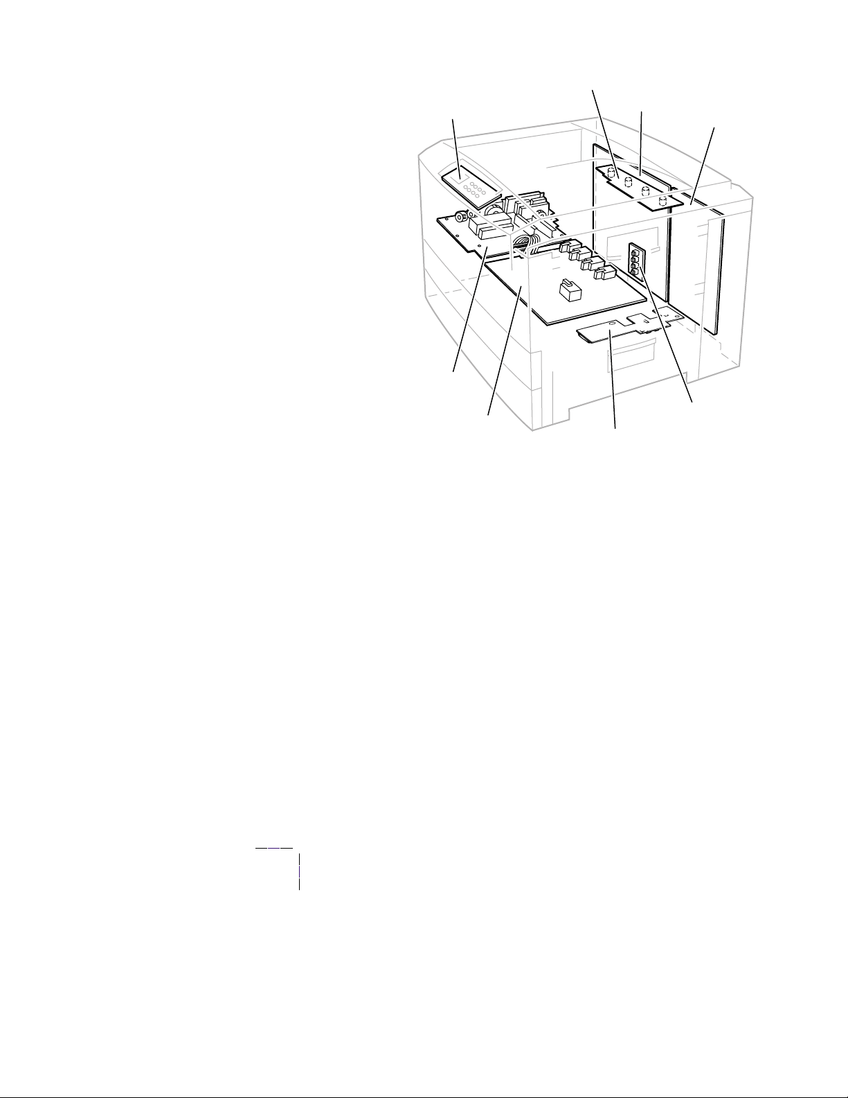
Print engine assemblies
Toner Sensor Board
Control Panel Board
Low Voltage
Power Supply
Board
System Controller Board
Engine Controller Board
High Voltage
Power Supply Board
Print engine circuit boards
Paper Size Sensor Board
Entrance Sensor Board
Service Guide
0725-64
5
Page 19
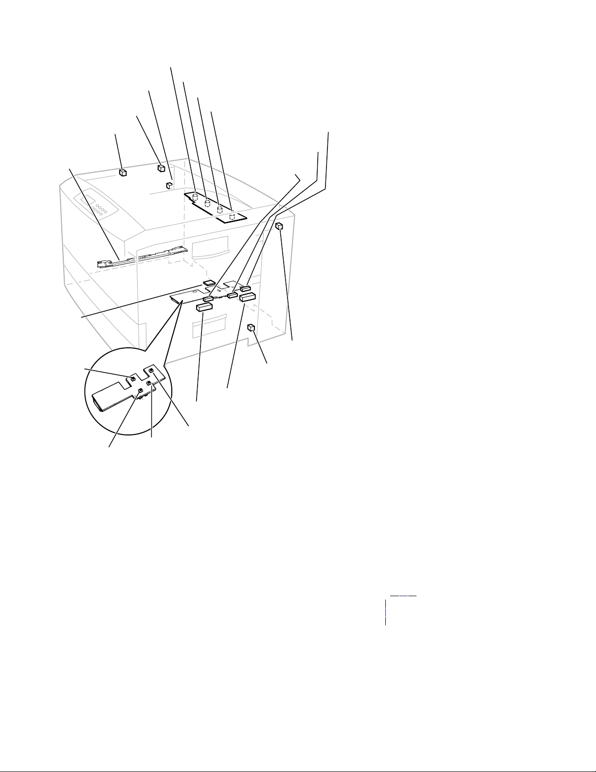
Face-up Tray Open Sensor
Stack Full Sensor
Exit Sensor
Color Registration
Sensor Assembly
Temperature/
Humidity
Sensor Board
Belt Entrance
Sensor
Cyan Toner Cartridge Sensor
Magenta Toner Cartridge Sensor
Yellow Toner Cartridge Sensor
Black Toner Cartridge Sensor
MBF Home Position
Sensor
MBFTransparency
Sensor
MPT Empty Sensor
Top Door
Open Switch
Right-side Door
Open Switch
Tray 1 Low Paper Sensor
Tray 1 Paper Out Sensor
Entrance Sensor
Registration Sensor
Print engine sensor and switch locations
6
Phaser 2135 Color Printer
Waste Toner Sensor
0725-63
Page 20
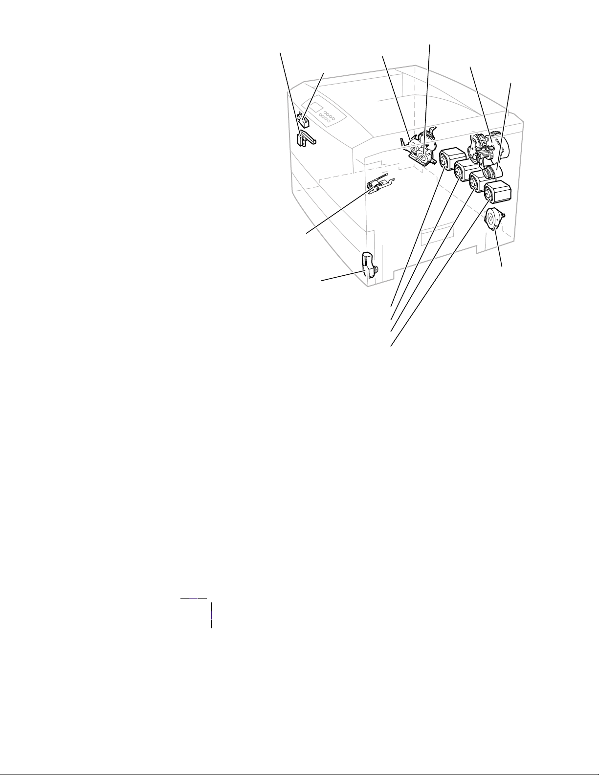
Duplex Solenoid
Fuser Motor
Exit Solenoid
Color Registration
Shutter Solenoid
Tray Lift Motor
Cyan Imaging Drum Motor
Magenta Imaging Drum Motor
Yellow Imaging Drum Motor
Black Imaging Drum Motor
Transfer Belt Drive Motor
Registration Motor
Registration Clutch
Paper Feed Motor
0725-62
Print engine motors, clutches and solenoids
Service Guide
7
Page 21
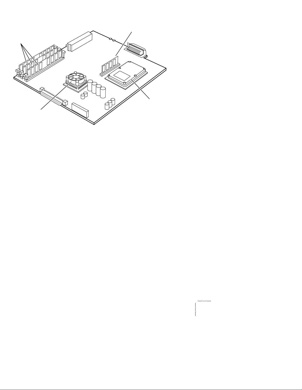
The image processor board
SDRAM
Fan cooled processor
Features of the controller board
ROM DIMM
Hard drive
0728-05
8
Phaser 2135 Color Printer
Page 22

The control panel
The control panel consists of eight labeled keys. These keys navigate the menu
system for printer operations. Two LEDs on the display indicate On Line and
active faults. The LCD display is two lines by twenty-four characters wide.
Menu up/down
Item up/down
Value up/down
C/
The control panel
Key 0 places the printer off-line or on-line. Key 4 is an Enter key. The pairs of
keys 1 and 5 are used to scroll through the main menu. Keys 2 and 6 navigate the
sub menus, and Keys 3 and 7 scroll sub-menu values. Key 6 cancels print jobs.
On Line LED
Green in color, this LED indicates when the printer is “On Line” and ready to
process data. When transitioning from “On Line” to “Off Line”, the LED flashes
at a rate of two times per second. When data is being received and processed, the
LED flashes at a rate of once per second.
! Fault
Red in color, this LED illuminates whenever operator intervention is required,
such as a paper jam in the printer.
Service Guide
9
Page 23
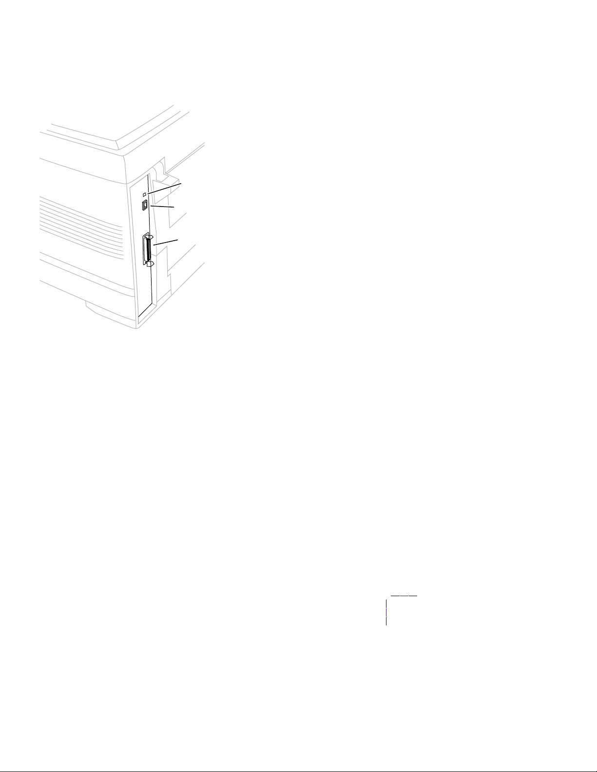
Rear panel
The rear panel of the printer features the host interface connectors:
Bi-directional parallel IEEE 1284-B connector.
■
Twisted Pair 10/100baseT Ethernet connector.
■
LEDs
Ethernet port
Parallel port
The printer rear panel
off
The LED LNK is
blinks
while data is transmitted to the host.
The LED SPD is
when the card is set for 16 MBPS.
10
Phaser 2135 Color Printer
when the printer is not installed on an Ethernet network, it
off
when the card is set for 4 megabits-per-second (MBPS), on
0728-03
Page 24

Accessing special operating modes
The printer can be placed in diagnostics or other operation modes by
simultaneously holding the
Menu Up (1)
the printer.
Entering special operating modes
Key Combination Mode
On Line (0) and
Enter (4)
Menu Up (1) and
Menu Down (5)
Menu Up (1) and
Enter (4)
Enter (4) and
Value Down (7)
This enables the
The Reset Menu is not normally available to the customer, as it contains
the ability to format devices and perform a factory reset of all items.
The control panel displays
To exit, switch the printer power off, then on.
This forces the
The Control Panel will display
Mode
on the second line. This indicates that the printer is ready to be
have its flash firmware updated.
To exit, switch the printer power off, then on.
Forces the printer into the
controller.
The control panel displays
that the printer is ready to enter diagnostics.
To exit, switch the printer power off, then on.
This reinitiates the NVRAM to factory defaults for all values except copy
counts and consumable counts.
The control panel displays
Reset Menu
Software Update Mode
and the
Ready
Engine Diagnostics Mode
Diag Mode 1?
Ready
Enter (4)
to become available at the control panel.
when completed.
Entering...
when complete.
keys as you turn on
on the parallel port.
on the first line
in the first line. This indicates
and Download
, bypassing the
System controller board LEDs
A power LED (PWR), when illuminated, indicates +5V is being supplied to the
system controller board.
The LED HDD, illuminates to flashes to indicate hard drive read/write activity.
LED GIO2 flashes to indicate proper CPU operation.
LED GIO3; off indicates 10baseT connection, on indicates 100baseT.
Service Guide
11
Page 25

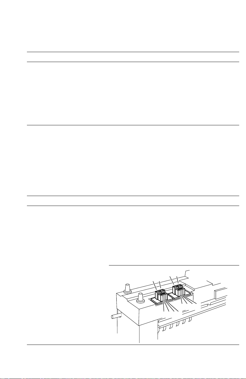
Paper tray size sensing
The position of a multi-slotted plate, at the rear of the paper tray, is set according
to the position of the tray’s paper guides. Upon insertion of the tray in the printer,
the plate’s four rows of slots activate four switches. The combinations of the slot
positions indicate the size of the paper in the tray.
Paper size detection
State of Microswitch Paper Size
SW1
(top)
0000No tray installed
0001B4
0010A4 (landscape)
0011A3-Nobi
0100Legal 13 in.
0101Legal 14 in.
0110A5
0111A6
1000B5 (landscape)
1001A3
1010A/Letter (landscape)
1011B/Tabloid
1100B5 (portrait)
1101Executive
1110A4 (portrait)
1111A/Letter (portrait)
SW2 SW3 SW4
(bottom)
Back of paper tray
Tray switch sensors and actuators
12
Phaser 2135 Color Printer
Paper tray
sensor board
0725-67
Page 26

Specifications
Physical dimensions
Dimensions Specification
Height: 46.0 cm (18.1 in.)
Width: 66.6 cm (26.2 in.)
Depth: 62.6.0 cm (24.6 in.)
Weight: About 72 kgs (158 lbs.)
Printer clearances
Clearances Specification
Top: 91.5 cm (36 in.)
Left: 30.5 cm (12 in.)
Right: 30.5 cm (12 in.)
Front: Unlimited for removal of consumables
Rear: 15.3 cm (6 in.) for connecting computer cable and power cord
Mounting surface
flatness:
Each additional lower tray adds 12.7 cm (5 ins.)
The lower tray deck adds 48 cm (19 ins.)
Each additional lower tray adds 16.8 kgs (37 lbs.). The lower tray
deck weights 57.7 kbs (127 lbs)
Maximum deviation of 50 mm (2 in.) from horizontal, side-to-side,
with all four feet in contact with the table surface.
Service Guide
13
Page 27

Functional specifications
Characteristic Specification
Printing process Electro-photographic, four color (CMYK) tandem transfer printing
Color medium Four toner cartridges each contain one of four colors: cyan, magenta,
Addressability Selectable 600 x 600 and 600 x 1200 dpi, text and graphics
Printing speed
pages per minute
(ppm)
yellow or black. The toner is a nonmagnetic, monocomponent
contact medium.
Time from paper-load to paper-eject for continuous printing:
Single-sided
A-size A4 B-size A3
Four-color: 20 21 11 11
Monochrome: 25 26 14.5 14.8
OHP: 6.6 6.4 na na
Cover/specialty: 10 10 6 5.8
Two-sided
Four-color: 10 10 5 5
Monochrome: 12 12 7 7
OHP: na na na na
Cover/specialty: na na na na
Print times do not include image processing time, which can vary
depending on image complexity.
Minimum printing
margins
Usable paper Tray: A-size (Letter), Legal, Executive (7.25 x 10.5 in.),
All sides 5 mm (0.2 in.),
A4-size (metric letter), SRA3, 12 x 18 in. B4, 8 x 13 in, A5
Tabloid (11 x 17 in.), A6, JIS B5, US Folio.
Use only premium bond laser printer or copier paper, transparency
film, card stock and glossy paper in Tray 1
Tray feed paper weight: 60 to 163 g/m2 (16 to 43 lb.)
Minimum paper size: 148 mm x 210 mm (5.83 x 8.27 in.)
Multi-sheet bypass feeder: A-size (Letter), Legal, Executive
(7.25 x 10.5 in.), 8 x 10 in., 12 x 18 in., A 4-size (metric letter),
SRA3, B4,
8 x 13 in, Tabloid (11 x 17 in.), A6, JIS B5, US Folio, A5. SP Folio,
, Statement,
Multi-sheet Bypass Feeder paper weight:
16 lb. to 54 lb. (60g/m2 to 203 g/m2)
Only
Xerox-brand Phaser 35-series A- and A4-size transparency film
is supported.
Automatic two-sided printing: 75 to 120 g/m2 (20 to 32 lb.)
A6 paper, transparency film, heavy card stock, and glossy paper are
not supported by Trays 2 thru 5
A-size A4 B-size A3
14
Phaser 2135 Color Printer
Page 28

Functional specifications
Characteristic Specification
Paper tray capacity Tray 1: 550 sheets of 20 lb. paper, 250 standard transparencies,
200 premium transparencies.
Tray 2 and Tray 5: 550 sheets of paper.
Multi-sheet Bypass Feeder: single sheet to 100 sheets of standard
paper. Varying number of envelopes and other special stock. The
Multi-sheet Bypass Feeder can use media in the 20 to 203 gm2
range.
Electrical specifications
Characteristic Specification
Primary line voltages 99 to 140 VAC (115 VAC nominal)
Primary voltage frequency
range
Power consumption 150 Watts during standby state, (1300 Watts max)
Primary voltage fusing 110 VAC configuration – 20 Amp
Secondary DC voltages Low Voltage Power Supply High Voltage Power Supply
RF emissions Both 110 and 220 VAC-configured instruments pass these
198 to 264 VAC (220 VAC nominal)
50 (48 to 52) or 60 (58 to 62) Hz
1400 Watts during warm-up
550 Watts operation average reference value
42 Watts during Energy Star state
220 VA C configuration – 15 Amp
+3.3 VDC (CH) -900 to -1.4 kV
+ 5 V (DB) -10 to 400/+300 V
+12 V (SB) -100 to -700 V
+ 32 V (TB) +1k to +7 kV
+3.8 V (FIX) 0 to 7 kV
standards: FCC Part 15 Class B
VDE Class B
EN60555-2 Class A
VCCI (CISPR 22:1997) Class B
Environmental specifications
Characteristic Specification
Temperature
Operating
Non-operating
Storage
Humidity
Operating
Non-operating
10o to 32o C (50oto 90oF)
0o to 32o C (32o to 90o F)
-10o to 43o C (-14 to 109o F) (with supplies)
Media should be acclimated 24 hours before using in the printer.
10 to 80% relative humidity, non-condensing
10 to 90% relative humidity, non-condensing
Media should be acclimated 24 hours before using in the printer.
Service Guide
15
Page 29

Environmental specifications
Characteristic Specification
Altitude
Operating
Non-operating
Vibration/shock
Operating
Non-Operating (vibration)
Non-operating (shock)
Acoustic Noise (operating) Standby: 45 dBa, Running: 54 dBa, Impulse: 57 dBa
0 to 2500 m (8,000 ft.) at 25oC
0 to 6000 m (20,000 ft.)
May drop any side or corner 50 mm (2 in.) without impairment of
subsequent operation.
On five mutually perpendicular axes: 0.5 g, 25-minute sweep, 5
to 200 to 5 Hz, 100 to 200 sec./sweep cycle. No resonant
frequencies below 50 Hz.
15 g, trapezoidal flared pulse, 20 msec each axis.
Regulatory specifications
The printer is a recognized component in conformance with the following
regulatory standards:
The packaged product meets ASTM D4169-93 and ASTM D4728-91
■
Transportation Standards.
Listed UL 1950 Information Processing and Business Equipment.
■
Certified CSA C22.2 No. 950 Safety of Information Technology
■
Equipment, Including Electrical Business Equipment.
GS licensed IEC 950 (1991) Second Edition; EN60950 Information
■
Processing and Business Equipment.
EN50022 (CISPR 22) Class B
■
EN61000-3-2
EN61000-3-3
VCCI (CISPR 22) Class B
FCC Class B (for 115 VAC equipment) pursuant to Sub-part J of Part 15.
■
ICES 03 Class B
16
Phaser 2135 Color Printer
Page 30

Error Codes and Messages
Error messages
The front panel displays error codes when it encounters certain system failures.
These error codes are discussed in the next topic. Except for media jams and other
such errors, when an error code first occurs, cycle power on the printer to see if
the error re-occurs.
Printer fault messages
Code Front panel message Service message
A6 Jam Inside Top Cover, Open Cover, See
Labels
1.
Ensure the correct weight and type of paper is loaded in the feeder. Also
ensure the paper is loaded correctly in the feeder.
2.
Clean the bypass feeder’s pick roller.
3.
Test the main feed motor as described in “Motor and clutch tests” on
page 69.
4.
Replace the main feed motor.
5.
Replace the engine controller board.
A7 Jam Inside Top Cover, Open Cover, See
Labels
1.
Ensure the correct weight and type of paper is loaded in the currently used
tray. Also ensure the paper is loaded correctly in the tray.
2.
Clean the duplex unit’s rollers.
3.
Test the duplex motor and clutch as described in “Motor and clutch tests”
on page 69.
4.
Replace the duplex unit.
5.
Replace the engine controller board.
A10 Jam Inside Top Cover, Open Cover, See
Labels
1.
Ensure the correct weight and type of paper is loaded in the currently used
tray. Also ensure the paper is loaded correctly in the tray.
2.
Clean the exit rollers.
3.
Ensure the exit rolls rotate freely when the exit roller gear train is rotated.
4.
At the rear of the printer, inspect the gate which directs the print to the
face-up output bin or the face-down output bin.
5.
Test the fuser motor (which drives the exit gear train) using the test
described in “Motor and clutch tests” on page 69.
6.
Replace the engine controller board.
A6-Bypass Feeder Jam
A7-Duplex Entry Jam
A10-Paper Output Jam
Service Guide
17
Page 31

Printer fault messages
Code Front panel message Service message
A11 Jam Inside Top Cover, Open Cover, See
Labels
1.
Ensure the correct weight and type of paper is loaded in the currently used
tray. Also ensure the paper is loaded correctly in the tray.
2.
Clean the pick and registration rollers.
3.
Ensure there are no obstructions in the paper path.
4.
Test the registration motor and clutch as described in “Motor and clutch
tests” on page 69. Replace the motor or clutch if necessary.
5.
Inspect the wiring for the registration clutch and registration motor.
6.
Replace the engine controller board.
A22 Jam Inside Top cover, Open Cover, See
Labels
1.
Ensure the correct weight and type of paper is loaded in the currently used
tray. Also ensure the paper is loaded correctly in the tray.
2.
Clean the pick and registration rollers.
3.
Ensure there are no obstructions in the paper path.
4.
Test the registration motor and clutch as described in “Motor and clutch
tests” on page 69. Replace the motor or clutch if necessary.
5.
Inspect the wiring for the registration clutch and registration motor.
6.
Replace the engine controller board.
B8 Jam Inside Duplex Unit, Open Cover, See
Labels
1.
Ensure the correct weight and type of paper is loaded in the currently used
tray. Also ensure the paper is loaded correctly in the tray.
2.
Clean the duplex unit’s rollers.
3.
Test the duplex motor and clutch as described in “Motor and clutch tests”
on page 69.
4.
Replace the duplex unit.
5.
Replace the engine controller board.
B13 Jam Inside Duplex Unit, Open Cover, See
Labels
1.
Ensure the correct weight and type of paper is loaded in the currently used
tray. Also ensure the paper is loaded correctly in the tray.
2.
Inspect and clean the eject rollers behind the fuser unit.
3.
Ensure the paper path leading to the duplex unit and the duplex unit’ s paper
path are both clear of obstructions.
4.
Inspect the operation of the solenoid activated separator gate the direct the
print into the duplex unit. Test the exit solenoid with the “Motor and clutch
tests” on page 69.
5.
Replace the duplex unit.
6.
Replace the engine controller board.
A11-Paper Feed Jam
A22-Feed Path Jam
B8-Duplex Jam
B13-Duplex Inverter Jam
18
Phaser 2135 Color Printer
Page 32

1.
2.
3.
4.
5.
1.
2.
3.
4.
5.
1.
2.
3.
3.
4.
4.
5.
1.
2.
Printer fault messages
Code Front panel message Service message
B21 Jam Inside Right Door A, Open Right Door A B21-Duplex Area Jam
1.
Ensure the correct weight and type of paper is loaded in the currently used
tray. Also ensure the paper is loaded correctly in the tray.
2.
Clean the duplex unit’s rollers.
3.
Test the duplex motor and clutch as described in “Motor and clutch tests”
on page 69.
4.
Replace the duplex unit.
5.
Replace the engine controller board.
C1 Close Tray 1, Tray 1 Not Detected C1-Check Tray 1
C2 Close Tray 2, Tray 2 Not Detected C2-Check Tray 2
C3 Close Tray 3, Tray 3 Not Detected C3-Check Tray 3
C4 Close Tray 4, Tray 4 Not Detected C3-Check Tray 4
C5 Close Tray 5, Tray 5 Not Detected C3-Check Tray 5
Ensure the tray is installed correctly.
Inspect and test the paper size sensors and the tray’s corresponding
sensor flags.
Replace the paper tray sensor board
Replace the paper tray.
Replace the engine controller board.
E1 Tray 1 Misfeed, Open Rt Door A and Tray 1 E1-Tray 1 Misfeed
E2 Tray 2 Misfeed, Open Rt Door B and Tray 2 E1-Tray 2 Misfeed
E3 Tray 3 Misfeed, Open Rt Door C and Tray 3 E1-Tray 3 Misfeed
E4 Tray 4 Misfeed, Open Rt Door D and Tray 4 E1-Tray 4 Misfeed
E5 Tray 5 Misfeed, Open Rt Door E and Tray 5 E1-Tray 5 Misfeed
Ensure the correct weight and type of paper is loaded in the tray. Also
ensure the paper is loaded correctly in the tray.
Clean the pick rollers.
Test the main feed motor as described in “Motor and clutch tests” on
page 69.
Replace the main feed motor.
Replace the engine controller board.
E9 Top Cover Open, Close Top Cover A E9-Top Cover A Open
Close the cover.
Inspect the switch and ensure the switch’s actuator is not broken.
Test the top cover open switch using the sensor test described in “Switch
scan test” on page 63.
Inspect the switch’s wiring harness.
Replace the engine controller board.
E12 Top Output Tray Full Remove Output E12-Output Bin Full, Top
Ensure the output bin full sensor flag operates freely.
T est the output bin full sensor using the test described in “Switch scan test”
on page 63.
Inspect the sensor and its wiring harness.
Replace the engine controller board.
Service Guide
19
Page 33

Printer fault messages
Code Front panel message Service message
E14 Close Duplex Unit, Duplex Unit Not Detected E14-Duplex Unit Not
1.
Ensure the duplexer is installed correctly.
2.
Inspect the connector at the rear end of the
duplexer unit.
3.
Inspect the wiring harness leading from the
duplexer unit interface connector to the
engine controller board.
4.
Replace the duplexer unit.
5.
Replace the engine controller board.
E18 Right Door A Open, Close Right Door A E18-Right Door A Open
E20 Right Door B Open, Close Right Door B E20-Right Door B Open
E21 Right Door C Open, Close Right Door C E21-Right Door C Open
E22 Right Door D Open, Close Right Door D E22-Right Door D Open
E23 Right Door E Open, Close Right Door E E23-Right Door E Open
1.
Ensure the cover’s sensor flag operates
freely.
2.
Test the output bin full sensor using the test
described in “Switch scan test” on page 63.
3.
Inspect the sensor and its wiring harness.
4.
Replace the engine controller board.
EA Black Imaging Drum Missing, Reseat Drum EA-Black Imaging Drum
EB Cyan Imaging Drum Missing, Reseat Drum EA-Cyan Imaging Drum
EC Magenta Imaging Drum Missing, Reseat Drum EA-Magenta Imaging Drum
ED Yellow Imaging Drum Missing, Reseat Drum EA-Yellow Imaging Drum
1.
Remove and install the drum unit.
2.
Inspect the spring-loaded drum contact assembly. Ensure they are clean
and move up and down freely. Remove the assembly and reseat it, if
necessary.
3.
Replace the engine controller board.
4.
Replace the printer unit chassis
Detected
Missing
Missing
Missing
Missing
20
Phaser 2135 Color Printer
Page 34

1.
2.
3.
4.
5.
3.
1.
2.
3.
1.
2.
Printer fault messages
Code Front panel message Service message
EE Transfer Belt Missing, Reseat Belt EE-Transfer Belt Unit
1.
Remove and re-install the transfer belt unit.
2.
Clean the transfer belt unit’s contact on the front-left side of the engine
chassis. Clean the corresponding contacts on the transfer belt unit.
3.
Install a new transfer belt unit.
4.
Replace the engine controller board.
5.
Replace the printer unit chassis.
EF Fuser Missing, Reseat Fuser EF-Fuser Unit Missing
1.
Remove and reinstall the fuser.
2.
install a new fuser.
3.
Replace the low-voltage power supply.
4.
Replace the engine controller board.
H1 Disk Read Error, Press Enter to Clear
A hard disk error was detected that prevented
data from being read from the disk.
H2 Disk Write Error, Press Enter to Clear
A hard disk error was detected that prevented
data from being written to the disk.
H3 Disk Full Error, Press Enter to Clear
A hard disk full error occurred that prevented
data from being written to the disk
Turn the printer off and on again.
Ensure the hard drive is properly installed.
Re initialize the hard drive. by scrolling to the Reset Menu and selecting
the submenu item Disk Init .
Replace the hard drive.
Replace the system controller board.
J3 Replace Fuser J3-Replace Fuser
Install a new fuser.
If a new fuser has been installed but the print engine continues to ask for a
new fuser, reset the fuser life count using the topic “Consumable count
initialization” on page 73.
Replace the engine controller board.
J4 Replace Tr ansfer Belt J4-Replace T r ansfer Belt
Install a new transfer belt.
If a new transfer belt has been installed but the print engine continues to
ask for a new transf er belt, reset the tr ansf er belt life count using the topic
“Consumable count initialization” on page 73.
Replace the engine controller board.
Missing
H1-Disk Read Error
H2-Disk Write Error
H3-Hard Disk Full
Service Guide
21
Page 35

Printer fault messages
Code Front panel message Service message
J5 Replace Yellow Imaging Drum J5-Replace Yellow Imaging
J6 Replace Magenta Imaging Drum J6-Replace Magenta
J7 Replace Cyan Imaging Drum J7-Replace Cyan Imaging
J8 Replace Black Imaging Drum J8-Replace Black Imaging
1.
Install a new drum unit.
2.
If a new drum unit has been installed but the print engine continues to ask
for a new drum unit, reset the drum unit life count using the topic
“Consumable count initialization” on page 73.
3.
Inspect the spring-loaded drum unit contacts (in a set of three). Ensure
they are clean and move up and down freely. Remove and reseat them, if
necessary.
4.
Replace the engine controller board.
J9 Y ellow Toner Empty Replace Yellow Toner J9-Yellow T oner Empty
J10 Magenta Toner Empty Replace Magenta Toner J10-Magenta Toner Empty
J11 Cyan Toner Empty Replace Cyan Toner J11-Cyan Toner Empty
J12 Black Toner Empty Replace Black Toner J12-Black Toner Empty
1.
Install a new toner cartridge.
2.
If a new cartridge has been installed but the print engine continues to ask
for a new cartridge, reset the toner cartridge life count using the topic
“Consumable count initialization” on page 73.
3.
Replace the drum unit.
4.
Replace the engine controller board.
L0 Load Tray # 1 Size 2 Type 3 Load Tray #, Size Type
1. Load the requested size and type of paper in the tray.
2. Ensure the tray is installed correctly.
3. Inspect and test the paper size sensors and the tray’s corresponding
sensor flags.
4. Replace the paper tray sensor board.
5. Replace the paper tray.
6. Replace the engine controller board.
Drum
Imaging Drum
Drum
Drum
22
Phaser 2135 Color Printer
Page 36

Printer fault messages
Code Front panel message Service message
T1 Fuser Upper Error T1 Power Off/On T1-Fuser Upper Error
T2 Fuser Lower Error T2 Power Off/On T2-Fuser Lower error
1. Remove and install the fuser.
2. Test the thermistors inside the fuser using the test described in “Switch
scan test” on page 63.
3. Replace the fuser.
4. Replace the low-voltage power supply.
5. Replace the engine controller board.
T29 Temp Sensor Error T29, Power Off/On T29-Temp Sensor Error
T30 RH Sensor Error T30, Power Off/On T30-RH Sensor Error
1. Test the temperature sensor or the relative humidity sensor using the
sensor test described in “Switch scan test” on page 63.
2. Inspect the wiring harness leading to the entrance sensor board.
3. Replace the temperature/humidity sensor board.
4. Replace the engine controller board.
T31 Roller Over Temp T31, Power Off/On T31-Roller Over Error
1. Inspect the fuser cooling fan. Ensure it is running correctly and is not
blocked.
2. Remove and install the fuser.
3. T est the thermistor inside the fuser using the test described in “Switch scan
test” on page 63.
4. Replace the fuser.
5. Replace the low-voltage power supply.
6. Replace the engine controller board.
T32 LED Over Temperature T32, Power Off/On T32-LED Over Temp Error
1. Ensure all the chassis cooling fan is operating and is not blocked.
2. Ensure the printer is operating in the correct temperature environment; the
printer’s Service Menu : Print Diag Summary test page lists the ambient
temperature sensed by the printer.
3. Replace the LED heads.
4. Replace the engine controller board.
Service Guide 23
Page 37

Printer fault messages
Code Front panel message Service message
U0 Engine ROM Error U0, Power Off/On U0-Engine ROM Error
U1 Engine RAM Error U1, Power Off/On U1-Engine RAM Error
U2 Engine EPROM Error U2, Power Off/On U2-Engine EPROM Error
U3 Engine EPROM Missing U3, Power Off/On U3-Engine EPROM Missing
U4 Engine SRAM Error U4, Power, Off/On U4-Engine SRAM Error
U5 Engine Control Error U5, Power, Off/On U5-Engine Control Error
1. Turn the printer off and then on
2. Reset the printer NVRAM using the procedure “Resetting NVRAM” on
page 85.
3. Replace the engine controller board.
U6 Power Supply Error U6, Power Off/On U6-Power Supply Error
1. Inspect the front and rear power supply fans. Ensure they is running
correctly and are not blocked. The front fan blows into the chassis. The
rear fan blows out from the chassis.
2. Turn the printer off and then on.
3. Replace the low-voltage power supply.
4. Replace the engine controller board.
U7 Feeder Home Error U7, Power Off/On U7-Feeder Home Error
1. Test the manual bypass feeder home sensor using the test described in
“Switch scan test” on page 63.
2. Inspect the sensor and its wiring harness.
3. Replace the engine controller board.
U8 Controller Fan Error U8, Power Off/On U8-Controller Fan Error
1. Inspect the electrical chassis fan to see if it is running and not blocked.
2. Inspect the fan’s wiring harness.
3. Replace the fan.
4. Replace the engine controller board.
U9 Supply Fan Error U9, Power Off/On U9-Supply Fan Error
1. Inspect the main cooling fan to see if it is running and not blocked.
2. Inspect the fan’s wiring harness.
3. Replace the fan.
4. Replace the engine controller board.
U10 Roller Position Error U10, Power Off/On U10-Roller Position Error
1. Ensure the correct weight and type of paper is loaded in the currently used
tray. Also ensure the paper is loaded correctly in the tray.
2. Clean the pick and registration rollers.
3. Ensure there are no obstructions in the paper path.
4. Test the registration motor and clutch as described in “Motor and clutch
tests” on page 69. Replace the motor or clutch if necessary.
5. Inspect the wiring for the registration clutch and registration motor.
6. Replace the engine controller board.
24 Phaser 2135 Color Printer
Page 38

Printer fault messages
Code Front panel message Service message
U12 Duplex I/F Error U12, Power Off/On U12-Duplex I/F Error
1. Turn the printer off and on.
2. Pull out the duplexer and inspect its connector at the right front corner (the
connector faces rearward). Inspect the printer’s corresponding connector
on the printer chassis (covered by a flexible metal plate).
3. Inspect the wiring harness leading from the engine control board to the
duplex unit connector.
4. Replace the duplex unit.
5. Replace the engine controller board.
U13 Tray 3 I/F Error U13, Power Off/On U13-Tray 3 I/F Error
U14 Tray 2 I/F Error U14, Power Off/On U14-Tray 2 I/F Error
U16 Tray 4 I/F Error U13, Power Off/On U13-Tray 4 I/F Error
U17 Tray 5 I/F Error U14, Power Off/On U14-Tray 5 I/F Error
1. Turn the printer off and then on.
2. Inspect the interface connector connecting the tray unit to the print engine.
Inspect the printer’s corresponding connector on the underside of the
printer. Inspect the wiring harness leading from the connector to the
engine control board.
3. Replace the engine controller board.
U15 Control Panel Error U15, Power Off/On U15-Control Panel Error
1. Turn the printer off and then on.
2. Reset the printer NVRAM using the procedure “Resetting NVRAM” on
page 85.
3. Replace the engine controller board.
U18 Yellow LED Error U18, Power Off/On U18-Yellow LED Bar
U19 Magenta LED Error U19, Power Off/On U19-Magenta LED Bar
U20 Cyan LED Error U20, Power Off/On U20-Cyan LED Bar Missing
U21 Black LED Error U21, Power Off/On U21-Black LED Bar Missing
1. Ensure the LED assembly is correctly installed.
2. Inspect the wiring harnesses leading to the LED assembly.
3. Replace the engine controller board.
U22 Yellow Toner Missing, Reseat Toner U22-Yellow Toner Missing
U23 Magenta Toner Missing, Reseat Toner U23-Magenta Toner Missing
U24 Cyan Toner Missing, Reseat Toner U24-Cyan Toner Missing
U25 Black Toner Missing, Reseat Toner U25-Black Toner Missing
1. Inspect the toner cartridge sensor flag. Ensure to moves properly and is
not broken.
2. T est the sensor using the test described in “Switch scan test” on page 63.
3. Inspect he toner sensor boards wiring harness.
4. Replace the toner sensor board.
5. Replace the engine control board.
U26 Yellow Drum Error U26, Power Off/On U26-Yellow Drum Error
Missing
Missing
Service Guide 25
Page 39

Printer fault messages
Code Front panel message Service message
U27 Magenta Drum Error U27, Power Off/On U27-Magenta Drum Error
U28 Cyan Drum Error U28, Power Off/On U28-Cyan Drum Error
U29 Black Drum Error U29 Power Off/On U29-Black Drum Error
1. Remove and install the drum unit.
2. Inspect the spring-loaded drum unit contacts (in a set of three). Ensure
they are clean and move up and down freely. Remove the assembly and
reseat it, if necessary.
3. Test the drum unit contacts using the Drum contact switch test listed in
“Switch scan test” on page 63.
4. Install a new drum unit.
5. Replace the engine controller board.
6. Replace the print unit chassis.
W16 Fuse Cut Error W16 - Fuse Cut Error
For the new Customer Replaceable
Consumable (imaging drums, transfer belt or
fuser) just installed, the printer did not detect
the CRC’s “new/used” fuse blow. An internal
fuse of a new CRC ordinarily blows a few
seconds after the CRC is installed. If the fuse
cannot be blown, then the consumable’s
counter can't be reset and the “consumable
expired / replace” messages will not go away.
1. Remove the CRC.
2. Cycle the printer’s power.
3. Install the CRC again. If the error still
occurs, try a different CRC.
4. If error reoccurs with a different CRC,
replace the engine controller board.
5. Replace the print unit chassis.
26 Phaser 2135 Color Printer
Page 40

System controller board diagnostic error codes
Code Test Possible Cause
1 Memory Bad memory DIMMs
2 Memory Speed Bad DIMMs or system controller board
3 CPU Tick Bad system controller board
4 System Timer Bad system controller board
5 BX Host Bridge Bad system controller board
6 PIIX4 PCI-ISA Bridge Bad system controller board
7 21152 PCI-ISA Bridge Bad system controller board
8 PCI-PCI Bridge Bad system controller board
9 IX Bad system controller board
10 Parameter Flash R/W not implemented
11 Strata Flash R/W not implemented
12 Strata Flash Boot Block
Integrity
13 Strata Flash File System
Integrity
14 STE100 Bad system controller board
15 VX2b-0 Bad system controller board
16 VX2b-1 Bad system controller board
17 VX2b-2 Bad system controller board
18 VX2b-3 Bad system controller board
19 Disk Identify Bad hard disk drive
20 Disk Read/Write Bad hard disk drive
21 Disk Read Capability Bad hard disk drive
22 Disk Write Capability Bad hard disk drive
23 Disk Data Format Check Bad hard disk drive
Bad system controller board
Bad system controller board
Service Guide 27
Page 41

These are error codes returned by the system controller board. In the event that
one of these errors occurs:
1. Cycle printer power to see if the error reoccurs.
2. Reseat the system controller board.
3. Replace the system controller board.
These errors can also be caused by the board’s hard drive or the RAM DIMMs.
System controller board fatal error codes
Code Description
00 Unknown. Replace the hard drive before replacing the controller board.
04 Video T ask
08 Serial Task
10 System Display Task
14 System Status Task
18 Startup, Key Press Processing, Menus Task
1C Parallel Port Read Buffer Manager
20 Parallel Port Write Buffer Manager
24 NVEE Manager
28 Scheduler
2C Job Log
30 Print File Task
34 Video Cleanup Task
3C Collation T ask
40 Parallel Port Hear Task
48 PostScript Task 1. Replace the hard drive before replacing the controller
board.
4C PostScript Task 2
50 PostScript_Wrapper Task
54 PCL Task. Replace the hard drive before replacing the controller board.
58 PJL T ask
78 Dequeue T ask
84 In-menu Print File Task
8C Alert Recovery Task
90 Sweeper T ask
94 SNMP Alert Task
98 SNMP Main Task
9C SNMP UDP Task
A0 SNMP DDP Task
A4 SNMP IPX Task
A8 Notification Manager
B4 Image Handler
C4 Job Manager
D0 PowerSa ver Task
D4 TIFF T ask
28 Phaser 2135 Color Printer
Page 42

Troubleshooting
This topic discusses troubleshooting the printer. Troubleshooting is discussed
with two approaches:
A step-by-step verification procedure that systematically confirms that
■
particular components of the printer are properly functioning until a
problem is found.
A symptom/cause scheme that lists particular printer failures or error
■
codes and their possible causes.
Fault History Log
The printer maintains a log file of the last 50 errors that have occurred. The most
recent error is displayed first.
To view the log:
1.
Turn on the printer.
2.
Press the
3.
Press the
4.
Press the
most recent error. Press the
Menu (5)
Item(6)
Value (7)
key to scroll to the
key to scroll to the menu item
key to scroll down the list of errors. The first item is the
Value (3)
Support Menu.
Show Fault History
key to scroll back up the list.
.
Service Guide
29
Page 43

Power on self-diagnostic test
Initial test. The following checks are automatically performed when the printer is
powered on:
1.
ROM check (loader). Checks ROM by comparing the sum of bits in the
received data unit by the number of bits in the transferred data unit.
2.
RAM check. Checks RAM by writing a preset data pattern in RAM, reading
the contents of RAM, and comparing the data read from RAM by the data
written in RAM.
3.
EEPROM check. Checks ID numbers stored in the fixed addresses of
EEPROM. Checks the content of the menu area by control firmwar e and the
engine area by engine firmware.
4.
Flash ROM check. Checks Flash ROM by writing a present data pattern in
Flash ROM, reading the contents of Flash ROM, and comparing the data
read from Flash ROM by the data written in Flash ROM.
5.
Mechanical check.
All the engine fans turned on and are checked to ensure they run
■
properly.
The fuser heaters activate to heat up the heated rollers.
■
■
The print engine checks to see that the imaging drums are installed.
■
The engine motors rotate to ensure that their rotation sensors are
detected.
■
A sensor check is made to determine if any paper is jammed in the
printer.
■
The print engine checks the presence of each toner cartridge.
■
Option unit check. Checks whether the optional units (such as the paper
tray 2, paper tray 3, duplex unit) have been installed before entering the
operation mode.
The print engine performs a color misalignment detection check by
■
laying down patches of toner on the transfer belt and reading their
relative positions to each other with the color registration sensor
assembly.
■
After the fuser reaches its idle temperature the printer is placed on line in
its READY state.
The print engine is initialized. If the startup page feature has not been disabled
and no error occurred with the printer, the printer prints a startup page.
30
Phaser 2135 Color Printer
Page 44

Print engine troubleshooting
This topic is a step-by-step procedure for systematically verifying particular
aspects of the printer's operation. Following this procedure should lead to the
cause of a printer's failure.
Testing the print engine controller board
1.
If the printer does not power up, or does not initialize, or the printer
initializes but the motors do not run properly, go to the later topic,
“Verifying power supply operation” on page 32.
2.
Observe that the
go to the later topic “Verifying power supply operation” on page 32.
3.
To ensure the print engine operates correctly, print one of its internal test
pages from its diagnostic menu as explained in the topic “Test printing” on
page 71.
If the printer prints a test print, then the printer's print engine is working
correctly. Proceed with the next topic, “Verifying printer operation by using its
self-test print” on page 32.
If the printer does not make the test print, then a problem exists with the print
engine. Proceed with the topic, “Verifying power supply operation” on page 32.
Ready
message is displayed on the front panel. If it is not,
Service Guide
31
Page 45

Verifying printer operation by using its self-test print
1.
If not already on, turn on the printer. If the printer does not power up, or
does not initialize, or the printer initializes but the motors do not run
properly, go to the next topic “Verifying power supply operation.”
2.
Verify that the system controller board’s health LED is flashing. The health
LED is viewable through the rear panel. If the health LED is not flashing,
then the system controller board is not working.
3.
When the
Ready
message is displayed, press the
Menu (1, 5)
buttons to
enter the menu.
4.
Press the
Item (2, 6
Menu (1, 5)
buttons to navigate to the
Print Menu
item. Press the
) keys to scroll through the list of available test prints. Select any
test print.
5.
Press
Enter
to print a test prints. The printer should print a test page from
the system controller board.
If the printer prints a test pattern, then the print engine controller board and the
system controller board are working correctly and the printer's problem resides
with the network or host interface.
Verifying power supply operation
Required tools
#1 Phillips screwdriver
■
■
Digital multimeter (DMM)
Verifying the power supply involves four steps:
Measuring the input and output voltages.
■
Checking the power supply fuse.
■
Checking the safety interlocks.
■
Ensuring the +5 VDC loop is complete.
■
Testing for a shorted motor which would shut down the power supply
■
or damage the engine controller board.
Measuring power supply voltages
1.
Turn off the printer and unplug it from its power outlet.
2.
AC Input:
being supplied to the printer. It should measure between 87 to 128 VAC
(115 VAC nominal) or 174 to 250 VAC (220 VAC nominal).
32
With the DMM set to measure AC voltages, measure for power
Phaser 2135 Color Printer
Page 46

3.
Power supply fans
: With the power switch on, ar e the fr ont and rear power
supply fans running? (Access the fans by removing the front and rear
covers.) If not, check the fans’ wiring harnesses (CN2 and CN5) to the
low-voltage power supply board; each fan’s voltage should measure 32 to
38VDC (the voltage drops to zero when you disconnect a fan). If the
voltage is not correct, replace the low-voltage power supply. Otherwise,
replace the non-functioning power supply fan.
DC Output:
With the DMM set to measure DC voltages, measure the voltages at
the POWER connector on the bottom of the print engine controller board for
+3.3VDC, +5 VDC, +12 VDC and +32 VDC. (You must remove the rear cover and
rear shield plate to access the engine controller board.)
If the voltages are not correct, inspect the wiring harness connecting the POWER
connector of the engine controller board to the CN1 connector of the low-voltage
power supply. If the harness is undamaged, replace the power supply.
POWER connector pinout
Pin Voltage/Signal Level Pin Voltage/Signal Level
1 +12 VDC 16 +3.3 VDC
2 No connection 17 +3.3 VDC
3 Ground 18 +3.3 VDC
4 Ground 19 No connection
5 Ground 20 Signal
6 Ground 21 Signal
7 +32 VDC 22 Signal
8 +32 VDC 23 Signal
9 +32 VDC 24 Signal
10 +32 VDC 25 Ground
11 +5 VDC 26 Ground
12 +5 VDC 27 Ground
13 +5 VDC 28 Ground
14 +5 VDC 29 Signal
15 +3.3 VDC 30 Signal
If DC voltages are not being output by the power supply, proceed to the next step,
“Inspecting the low-voltage power supply fuse” on page 34.
If the +5 and +32 VDC voltages measure correctly, but the printer does not operate
correctly, then proceed to the topic, “Safety interlocks” on page 34.
Service Guide
33
Page 47

Inspecting the low-voltage power supply fuse
The 115 VAC power supply features a 20 A fuse. The 220 V AC power supply fuse
uses a 15 A fuse.
1.
Turn off the printer.
2.
Disconnect the power cord from the printer.
3.
Remove the front cover as described in “Front cover” on page 90.
4.
Remove the AC power switch (1 screw) and the front power supply fan as
described in “Front power supply fan” on page 95. The fuse is now
accessible.
If the fuse is good, but the printer's power supply does not output DC voltages,
replace the low-voltage power supply. Check the +% v loop circuit as described
earlier in “Ensuring the +5 VDC loop is complete” on page 35.
Safety interlocks
The printer features two safety interlock switches:
Top door-opened switch.
■
Right door-opened switch.
■
When the top cover switch is opened, the +32 VDC supply to the motors is shut
down, as well as the high-voltage power supply and an error message is
displayed on the front panel. When the right cover door is opened, the +32 VDC
supply to the duplex unit and high-voltage power supply is disabled.
1.
Turn off the printer.
2.
With a DMM set to measure resistance, test each switch when it is opened
and closed.
3.
Inspect each switch’s wiring harness for pinches, nicks or open connections.
If you find a switch that is defective, replace it. If no motors appear to be at fault,
replace the engine controller board.
34
Phaser 2135 Color Printer
Page 48
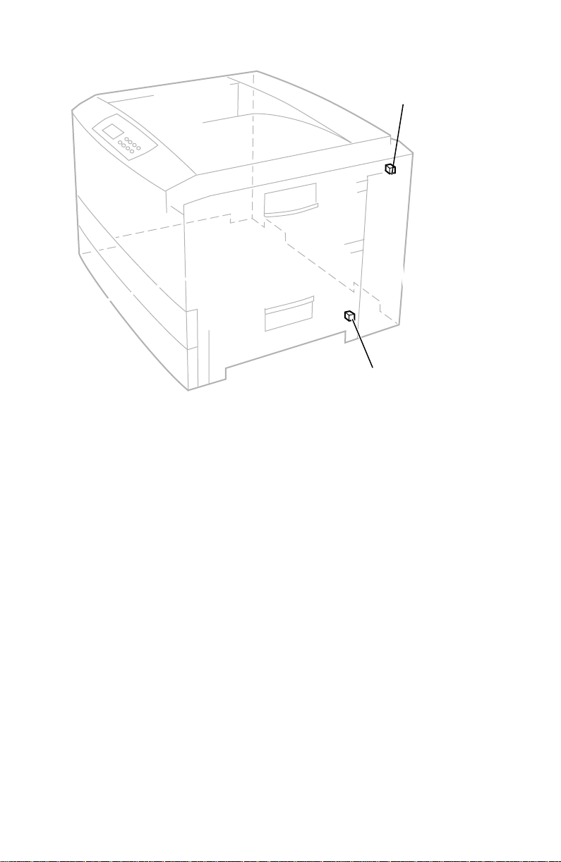
Door safety interlock switches
Top Cover
Open Switch
Front Cover
Open Switch
0725-63
Ensuring the +5 VDC loop is complete
The +5 voltage from low-voltage power supply is routed out of the power supply
connector CN1, via a wiring harness, to the POWER connector the engine
controller board, through surface-mount fuse F6, out the engine controller board
via the ribbon cable OPTN to the toner sensor board. The +5V is then routed back
out the toner sensor board through its power supply harness to the low-voltage
power supply connector CN 2.
Upon power-up, if the low-voltage power supply does not detect the return of the
+5 VDC, then the power supply will immediately shut-down. You may see the
CPU fan “bump” or the engine board LED (LED2) flash. To troubleshoot the loop:
1.
Test surface-mount fuse F6 for continuity. It is located on the upper-right
corner of the engine controller board next to the REG connector. If the fuse
is opened, replace the engine controller board.
2.
Inspect the two power wiring harnesses and the ribbon cable that carry the
+5 VDC loop. Ensure they are properly connected. The wiring harness
leading form the toner sensor board to the power supply features an
interconnect next to the rear hinge. Ensure it is properly connected.
Service Guide
35
Page 49

3.
Disconnect the POWER wiring harness (red wire bundle) from the engine
controller board. Also, disconnect the power wiring harness interconnect
connecting the toner sensor board’s white wire harness to the low-voltage
power supply board’s dark-gray wire harness. The interconnect is located
by the rear hinge.
Run a jumper wire from the +5V pins of the first wiring harness (pins 11 14, red wire bundle) to the +5V pin (pin 9, dark-gray wire bundle) of the
second power wiring harness. (With the jumper wire, you are bypassing
the engine controller board, the OPTN ribbon cable and the toner sensor
board).
Turn the printer on. If the jumper connection is correct, the low-voltage
power supply will start and the power supply fans will run. This indicates
the problem lies with the engine controller board or the toner sensor board
or their wiring. If the low-voltage power supply does not turn on, it is
probably bad. (Ensure your jumper connection is correct.)
Testing for a shorted motor
1.
Remove the top and rear covers.
2.
Disconnect the motor harnesses and verify motor resistances (see the
following topic).
3.
Refer to the topic “Wiring Diagram” on page 215 for a diagram that locates
each connector.
4.
Turn on the printer again to see if it overloads now that the motors are
disconnected from the engine driver board.
If the power supply still does not function, replace it.
36
Phaser 2135 Color Printer
Page 50
Motor and fuser roller resistances
1.
Turn off the printer and disconnect the power cord.
2.
With a DMM set for measuring resistance, test each motor's windings for
correct resistance (disconnected from the printer).
Motor and fuser roller resistances
Motor Measure between ... Resistance
~3
Yellow drum unit motor
Magenta drum unit motor
Cyan drum unit motor
Black drum unit motor
Between motor Pins 1 and 2
Between motor Pins 3 and 4
All the drum motors connect to
connector ID at the top of the
engine controller board
Black Pins 1 thru 4
Yellow Pins 5 thru 8
magenta Pins 9 thru 12
Cyan Pins 13 thru 16
Transfer belt motor
Registration motor
Fuser motor
Main feed drive motor
Between motor Pins 1 and 2
Between motor Pins 3 and 4
The transfer belt motor
connects to connector
BELTHET pins 5 thru 8
The feed motor connects to
connector HOPFF pins 1 thru 4
The main motor connects to
connector HOPFF pins 5 thru 8
Tray lift motor Between motor Pins 1 and 2 ~100
Fuser unit
Upper Roller
Between Pins A and B
New fuser: The resistance
between pins C and D of the
lower roller will be O Ω, a fuse.
Used fuser: The fuse between
pins C and D of the lower roller
Between Pins C and D
Between Pins E and F
Lower Roller
Between Pins A and B
Between Pins C and D
Between Pins E and F
will be open. The fuse indicates
a new fuser and is blown within
seconds of being installed to
indicate a fuser now in use.
B A
B A
Ω
~3
Ω
~8
Ω
~8
Ω
Ω
2
Ω
Open
~360 at 25
3
Ω
0 Ω or open
(fuse)
~360 at 25
o
C
o
C
C D E F
C D E F
Underside of fuser
Service Guide
-
37
Page 51

Media jams and the paper path
Required tools
■ #1 Phillips screwdriver
■ DMM
Jams fall into the following four categories:
Media-based problems
■
Paper-picking errors
■
Printing jams
■
Paper-ejecting errors
■
Media-based problems
Media problems
1.
Check that the correct type of media is being used. The customer should be
using a quality laser printer paper. The printer may have trouble picking
slick-finish paper.
2.
Inspect the paper for bent, torn or folded corners.
3.
Ensure that the correct media is loaded in the paper tray.
4.
Only Xerox-brand 35-Series transparency film for this printer should be
used from Tray 1 or from the multi-sheet bypass feeder.
5.
Refer to the media specifications in the table “Functional specifications,” on
page 17.
Multiple-sheet pick
1.
Is the paper in good condition and appropriate for a laser printer? Quality
office laser printer paper works best.
2. Is the printer printing within its environmental specifications? Print the
Diagnostic Summary Page to determine the printer’s condition.
3. Ensure the paper is correctly loaded in the tray.
4. Clean the pick rollers with a clean, dry, lint-free wipe if debris is visible.
5. Replace the paper pick rollers.
6. Check the tray’s retard roller for damage.
7. Replace the paper tray.
38
Phaser 2135 Color Printer
Page 52

The media skews passing through the paper path
1. Make sure that the media is properly installed in the tray.
2. Does the pick-up roller pick up evenly? Is it clean? Clean it with a clean,
dry, lint-free cloth if debris is visible.
3. Is the paper tray damaged or obstructed?
4. Are the tray's side paper guides snugly adjusted against the stack of media?
The guides should be neither too loose nor too tight.
5. The problem occur when printing from a different tray?
6. Is there an obstacle blocking the paper path?
7. Is the media excessively curled?
8. Is the customer using an appropriate type of media – a type the printer can
handle?
9. Ensure the corners or the paper are under the tabs in the corners of the tray.
10. Replace the paper pick rollers.
The paper tray indicates it is empty when it is not
The procedure for troubleshooting this problem applies to the lower tray
assembly as well.
1. Does the paper empty flag properly interrupt the paper empty sensor?
Remove the paper tray and actuate the paper-empty flag located to the left
of the pick rollers.
2. Test the sensor using the service tests described in “Switch scan test” on
page 63.
3. Does the tray lift motor raise the loaded paper up to the sensor flag when
the tray is installed? Remove most of the paper from the tray, reinsert the
tray in the printer and then observe the tray paper level indicator on the
front of the tray. The indicator should move from a level full indication
(tray lift in lowest position) to a near-empty indication (tray lift in a higher
position).
Ensure the tray lift mechanism in the tray moves freely. If you do not hear
the tray lift motor operate, test the motor with the motor test in “Motor and
clutch tests” on page 69. Replace the tray lift motor, if necessary. If the
motor runs but the paper is not raised, replace the main feeder assembly.
4. Replace the engine controller board.
Service Guide 39
Page 53

Jams
Wrong media
1. Ensure the correct media type and size is loaded in the correct tray. For the
multi-sheet bypass feeder, ensure the loaded media matches the control
panel settings.
2. Inspect the paper tray for damage to the tray’s paper size sensor actuators.
3. Test the printer’s paper size sensors using the service test “Switch scan test”
on page 63. If the sensors test ok, then the engine controller board is
probably bad.
4. Replace the paper size sensor board’s wiring harness.
Paper jams at the paper tray
1. Is the paper in good condition and appropriate for a laser printer?
2. Is the printer printing within its environmental specifications? Print the
Diagnostic Summary Page to determine the printer’s environmental
conditions.
3. Are the pick rollers dirty? If so, clean them if debris is visible and try
printing again.
4. Remove the paper tray and inspect the paper tray lift levers on the
inner-sides of the paper tray cavity. Inspect the tray’s paper lift mechanism.
5. Does the paper feed motor run? Check the motor’s wiring harness and
connection (HOPFF) to the engine controller board.
6. Replace the main feeder assembly (it contains the paper feed motor).
7. Check the gear train for broken teeth and proper installation.
8. Replace the pick rollers.
9. Does the pick clutch work properly? If not, replace it.
10. Replace the engine controller board.
40 Phaser 2135 Color Printer
Page 54

Manual bypass feeder feed jams
1. Is the paper in good condition and appropriate for a laser printer?
2. Is the printer printing within its environmental specifications? Print the
Diagnostic Summary Page to determine the printer’s environmental
conditions.
3. Do not overload the manual bypass tray; otherwise jams will occur.
4. If debris is visible, clean the manual bypass feed pick roller. Replace the
roller, if necessary.
5. Test the manual bypass feeder sensors using the service test “Switch scan
test” on page 63.
6. Inspect the wiring harness from the manual bypass feeder to the engine
controller board.
7. Replace the manual bypass feeder assembly.
8. Replace the engine controller board.
Paper jams at the registration rollers
1. Ensure that the pick-up rollers are clean. Clean them with a clean, dry,
lint-free cloth if debris is visible.
2. Check the paper path for burrs or foreign obstructions that could block the
movement of a sheet of paper.
3. Clean the registration rollers with a clean, dry, lint-free wipe if debris is
visible.
4. Test, and if necessary, replace the registration motor. Test the motor using
the service test “Motor and clutch tests” on page 69.
5. Does the registration roller electric clutch operate correctly? Operate it with
the service test “Motor and clutch tests” on page 69.
6. Transparency film. Use only Xerox 35-series transparency film meant for
this printer.
Paper jams at the transfer belt
1. Check for a paper scrap in the paper path.
2. Is the transfer belt assembly correctly installed?
3. Test the transfer belt motor using the service test “Motor and clutch tests”
on page 69.
Service Guide 41
Page 55

Fuser jams
1. Is the paper in good condition and appropriate for a laser printer?
2. Is Xerox Series-35 transparency film being used.
3. Is the printer printing within its environmental specifications? Print the
Diagnostic Summary Page to determine the printer’s environmental
conditions.
4. Test the fuser motor using the service test “Motor and clutch tests” on
page 69.
5. Does the exit sensor flag properly actuate its sensor? Use the service test
“Switch scan test” on page 63 to test the senor.
6. Does the jam occur only during a two-sided print? Is so the duplex
solenoid may not be operating correctly and the print is jamming in the
fuser.
7. Replace the fuser.
8. Replace the engine controller board.
Eject jams
1. Is the paper in good condition and appropriate for a laser printer? Is the
paper curling?
2. Is the printer printing within its environmental specifications? Print the
Diagnostic Summary Page to determine the printer’s environmental
conditions.
3. Is the jam caused by a heavy, stiff paper being printed to the face-down
tray? In such cases, a lighter grade of paper should be used or face-up
mode to the side output tray should be used.
4. Is the paper excessively curved after passing through the fuser? Try
flipping the paper over in the paper tray. Also, for A-, A4- and B5-sized
paper , re-orient the paper in the tray so the short edge feeds into the printer.
5. Clean all the eject rollers with a clean, dry, lint-free wipe if debris is visible.
6. Does the exit sensor flag properly actuate its sensor? Test the sensor using
the service test “Switch scan test” on page 63.
7. Replace the engine controller board.
42 Phaser 2135 Color Printer
Page 56

Jams in the duplex unit
1. Is the duplex unit correctly installed?
2. Clean the rollers inside the duplex unit with a clean, dry, lint-free wipe if
debris is visible.
3. Inspect the duplex unit for foreign objects such as a scrap of paper.
4. Inspect the duplex unit’s electrical connector for damage.
5. Does the duplex unit’s sensors operate correctly? Test the sensors using the
service test “Switch scan test” on page 63.
6. Test the duplex motor using the service test “Motor and clutch tests” on
page 69.
7. Replace the duplex unit.
8. Replace the engine controller board.
No imaging drum installed
1. Ensure that the imaging drums are properly installed.
2. Check the high-voltage terminal connectors for the imaging drum to ensure
that they are not damaged.
3. Replace the imaging drum.
Imaging drum up/down error
1. Cycle the printer power to see if the problem clears.
2. Ensure that each imaging drum unit is correctly installed and that each
unit’s drum contact assembly (a set of three spring-loaded pins) is not
damaged. Ensure that each contact moves up and down freely and is not
contaminated with toner. Remove an assembly from the printer to inspect,
if necessary.
3. Open the top cover, defeat the top cover open switch, and observe if the
color imaging drum unit are lifted up and down.
4. Test the drum contact assemblies using service test “Switch scan test” on
page 63. If a drum contact assembly is damaged, replace it.
5. Does each imaging drum motor rotate. Test them using the service test
“Motor and clutch tests” on page 69. Replace the main motor assembly, if
indicated.
6. Inspect the gear drive for each imaging drum unit for damage.
7. Replace the engine controller board.
Service Guide 43
Page 57

Fan error
1. Is power supplied to pin 1 of the fan? If yes, replace the fan.
2. Inspect the fan’s wiring harness for damage.
3. Replace the low-voltage power supply
4. Replace the engine controller board.
Fuser unit error
1. Does the error occur immediately after the printer is turned on? Replace
the fuser.
2. Check that AC voltage supplied to the printer is correct.
3. Does the fuser get hot? If not, replace the fuser.
4. If the fuser does warm up, verify that it is reaching the correct temperature
by running the service test “Switch scan test” on page 63.
5. If the fuser does not get warm. Does AC voltage appear between Pins 1 and 2
of CN 4-1 and CN 4-2 of the fuser connector. These pins connect to Pins A
and B of the fuser (illustrated below) when the fuser is installed. Remove
the fuser to check. If not, replace the power supply.
B A
B A
C D E F
C D E F
Underside of fuser
0728-02
Bear in mind that the correct AC voltage may be present at Pins 1 and 2 of
CN 4-1 and CN 4-2 even though the drivers ICs feeding these pins are
damaged and cannot deliver the current required by the fuser heaters.
6. Replace the engine controller board.
7. Replace the low-voltage power supply.
44 Phaser 2135 Color Printer
Page 58

Other problems
These problems may be indicated as errors on the front panel.
The printer continuously displays “Booting” or “Initializing.”
The most likely cause is that the system controller board has not successfully
loaded its EEPROM contents (instructions) into RAM. The health indicator LED
(heart beat) usually indicates such an error state by being on or off but not
flashing. All print engine operation halts, and will only become ready when the
system controller board successfully boots.
1. Re-powering the printer, or perform a NVRAM reset may fix this problem.
2. To verify if the system controller board has failed:
a. Power down the printer, and remove the system controller board.
b. Power-up the printer. Wait at least 5 minutes while the print engine
initializes. If there was a problem with the system contr oller boar d,
it will now not affect the print engine controller board.
c. If the print engine powers up correctly, a traveling “
around the control panel display. If not, then your problem is most
likely associated with the print engine controller board, and you
will need to replace it. If, however, you see the traveling “*”, then
the most likely cause is the system controller board.
d. Turn off the printer and reseat the system contr oller boar d and turn
on the printer to determine if seating was the problem.
e. Turn off the printer and systematically remove a RAM DIMM and
turn on the printer.
f. Replace the system controller board.
” moves
*
False “No toner cartridge installed” message
1. Ensure that the toner cartridge is correctly installed. Reseat the toner
cartridge.
2. Replace the toner cartridge.
3. Test the toner cartridge sensor board using the service test “Switch scan
test” on page 63.
4. Replace the engine controller board.
False “No fuser unit installed” message
1. Ensure that the fuser unit is correctly installed.
2. Check the condition of fuser units’s connector and their corresponding
receptacles on the print engine (under the fuser unit).
3. Replace the fuser unit.
4. Replace the engine controller board.
5. Replace the low-voltage power supply.
Service Guide 45
Page 59

Right-side door indicated being open when it is closed
1. Inspect that the front door’s interlock for damage.
2. Check the interlock switch for +32 V. Replace the switch if necessary.
3. Check its wiring harness.
4. Replace the engine controller board.
5. Replace the power supply if +32 volts is not present.
High temperature error
1. Check the fans for proper operation.
2. Replace the low-voltage power supply unit.
3. Replace the engine controller board.
Low temperature error
If the fuser is cold,
4. Ensure the fuser unit is properly installed.
5. Check the fuser unit’s connection and wiring.
6. Replace the fuser unit.
7. Replace the low-voltage power supply.
8. Replace the engine controller board.
If the fuser is hot,
1. Replace the fuser
2. Replace the engine controller board
Invalid memory DIMM
1. Upon power-up, the system controller board checks each DIMM for
information such as data width, clock delay, number of address columns
and row, refresh rate and more. If the DIMM does not meets the required
specifications the printer displays an “Invalid memory DIMM” error
message and then continues the boot-up process.
46 Phaser 2135 Color Printer
Page 60

Printing and print quality problems
Required tools
■ #1 Phillips screwdriver ■ Conductive grease
■ Volt-ohm-meter (VOM) ■ Ruler
Light or blurred images
1. Is the correct paper being used
in the printer?
2. Are the toner cartridges low?
3. Are any of the imaging drum
reaching their end-of-life?
Replace them if they are.
4. Do the imaging drum units
make good connection to their
power terminals?
5. Are the LED heads dirty? Clean
each head with a clean,
alcohol-soaked, lint-free cloth.
6. Are the LED heads wiring
harnesses undamaged and
properly seated?
7. Is +3.8V (red wire) supplied to
Pin 3 of each LED head
assembly? If yes, replace the
LED head assembly.
8. Is +3.8 V supplied to the
POWER connector pins 1, 2, 3,
4, 5, 6, 7 and 8 on the junction board or at the 16-pin interconnect near the
top cover hinge (under the top shield plate). Inspect the junction board’s
wiring connectors. If the voltage is not OK, replace the low-voltage power
supply.
9. If +32 volts supplied to the POWER connector pins 7, 8, 9 and 10 on the
engine controller board? Inspect the wiring harnesses or replace the
low-voltage power supply.
10. Is +32V supplied to the HVOLT connector Pin 5 of the engine board. If not
replace the engine board. (Transfer the old engine controller board’s
EEPROM (lower-right corner of board) to the new engine contr oller boar d.)
11. Inspect the high-voltage wiring harnesses.
12. Replace the high-voltage power supply.
Service Guide 47
Page 61

Dark, stained background
1. Determine if any of the imaging
drums were exposed to light for
an extended amount of time. If
so, replace any unit which was.
2. Examine the fuser rollers for
contamination. Replace the
fuser if they are.
3. Ensure the media type is
correctly set.
4. Are the power supply fans both
running? A heat build-up
under the imaging units can
cause toner to stain the print’s
background.
5. Do the imaging drum units
make good connection to their
power terminals?
6. Are the LED heads wiring
harnesses undamaged and
properly seated?
7. Is +3.8V (red wire) supplied to
Pin 3 of each LED head assembly? If yes, replace the LED head assembly.
8. Is +3.8 V supplied to the POWER connector pins 1, 2, 3, 4, 5, 6, 7 and 8 on
the junction board or at the 16-pin interconnect near the top cover hinge
(under the top shield plate). Inspect the junction board’s wiring connectors.
If the voltage is not OK, replace the low-voltage power supply.
9. If +32 volts supplied to the POWER connector pins 7, 8, 9 and 10 on the
engine controller board? Inspect the wiring harnesses or replace the
low-voltage power supply.
10. Is +32V supplied to the HVOLT connector Pin 5 of the engine board. If not,
replace the engine board. (Transfer the old engine controller board’s
EEPROM (lower-right corner of board) to the new engine contr oller boar d.)
11. Inspect the high-voltage wiring harnesses.
12. Replace the high voltage power supply.
48 Phaser 2135 Color Printer
Page 62

Blank print
1. Do the imaging drum units
make good connection to their
power terminals?
2. Are the LED heads wiring
harnesses undamaged and
properly seated?
3. Is +3.8V (red wire) supplied to
Pin 3 of each LED head
assembly? If yes, replace the
LED head assembly.
4. Is +3.8 V supplied to the
POWER connector pins 1, 2, 3,
4, 5, 6, 7 and 8 on the junction
board or at the 16-pin
interconnect near the top cover
hinge (under the top shield
plate). Inspect the junction
board’s wiring connectors. If
the voltage is not OK, replace
the low-voltage power supply.
5. If +32 volts supplied to the
POWER connector pins 7, 8, 9
and 10 on the engine controller
board? Inspect the wiring harnesses or replace the low-voltage power
supply.
6. Is +32V supplied to the HVOLT connector Pin 5 of the engine board. If not,
replace the engine board. (Transfer the old engine controller board’s
EEPROM (lower-right corner of board) to the new engine contr oller boar d.)
7. Inspect the high-voltage wiring harnesses.
8. Replace the high voltage power supply.
Service Guide 49
Page 63

Black stripe in direction of paper travel
Note A-size prints are normally
processed through the printer
with the short edge of the print
parallel to the direction of the
paper path making print artifacts
parallel to the short edge of the
print.
B-size prints are processed
through the printer with the long
edge of the print parallel to the
paper path making artifacts
parallel to the long axis of the
print.
Leading Edge
1. Do the imaging drum units make
good connection to their power
terminals?
2. Are the LED heads wiring
harnesses undamaged and
properly seated?
3. Is +3.8V (red wire) supplied to
Pin 3 of each LED head
assembly? If yes, replace the
LED head assembly.
4. Is +3.8 V supplied to the POWER connector pins 1, 2, 3, 4, 5, 6, 7 and 8 on
the junction board or at the 16-pin interconnect near the top cover hinge
(under the top shield plate). Inspect the junction board’s wiring connectors.
If the voltage is not OK, replace the low-voltage power supply.
5. If +32 volts supplied to the POWER connector pins 7, 8, 9 and 10 on the
engine controller board? Inspect the wiring harnesses or replace the
low-voltage power supply.
6. Is +32V supplied to the HVOLT connector Pin 5 of the engine board. If not
replace the engine board. (Transfer the old engine controller board’s
EEPROM (lower-right corner of board) to the new engine contr oller boar d.)
7. Inspect the high-voltage wiring harnesses.
8. Replace the high voltage power supply.
50 Phaser 2135 Color Printer
Page 64

White stripe in direction of paper travel
Note A-size prints are normally
processed through the printer
with the short edge of the print
parallel to the direction of the
paper path making print artifacts
parallel to the short edge of the
print.
B-size prints are processed
through the printer with the long
edge of the print parallel to the
paper path making artifacts
parallel to the long axis of the
print.
Leading Edge
1. Look for dirt or contamination
on the LED heads. Clean them
with a clean, alcohol-soaked,
lint-free wipe.
2. Do the imaging drum units make
good connection to their power
terminals?
3. Are the LED heads wiring
harnesses undamaged and
properly seated?
4. Is +3.8V (red wire) supplied to Pin 3 of each LED head assembly? If yes,
replace the LED head assembly.
5. Is +3.8 V supplied to the POWER connector pins 1, 2, 3, 4, 5, 6, 7 and 8 on the
junction board or at the 16-pin interconnect near the top cover hinge (under
the top shield plate). Inspect the junction board’s wiring connectors. If the
voltage is not OK, replace the low-voltage power supply.
6. If +32 volts supplied to the POWER connector pins 7, 8, 9 and 10 on the
engine controller board? Inspect the wiring harnesses or replace the
low-voltage power supply.
7. Is +32V supplied to the HVOLT connector Pin 5 of the engine board. If not
replace the engine controller board. Transfer the old engine controller
board’s EEPROM (lower-right corner of boar d) to the new engine contr oller
board.
8. Inspect the high-voltage wiring harnesses.
9. Replace the high voltage power supply.
Service Guide 51
Page 65

Poor fusing, toner offsetting
1. Is a supported paper type being
used? Try printing on a different
brand of paper.
2. Is the fuser unit properly
installed and making good
electrical contact with the print
engine? Inspect its connector.
3. Inspect the fuser. Are its rollers
contaminated or damaged?
4. Ensure the media type is
correctly set.
5. Does AC voltage appear between
Pins 1 and 2 of CN 4-1 and
CN 4-2 of the fuser connector.
These pins connect to Pins A and
B on the fuser’s underside when
the fuser is installed; remove the
fuser to check. If not, replace the
power supply.
6. Is the resistance of the fuser’s
upper roller thermistor (at room
temperature) between 190 to 980 Ω? If not replace the fuser.
7. Is the resistance of the fuser’s lower roller thermistor (at room temperature)
between 190 to 980 Ω? If not replace the fuser.
8. Is the fuser temperature correct during printing? Run the maintenance
mode fuser test “Test printing” on page 71 and check the temperature
displayed on the controller panel.
9. Replace the engine controller board. Transfer the old engine controller
board’s EEPROM (lower-right corner of boar d) to the new engine contr oller
board.
Offsetting and fuser temperature. Offsetting occurs on specialty paper if the
fuser’s temperature does not match the paper loaded in the multi-sheet bypass
feeder . For cold-of fsetting, characterized by toner fl aking of f the completed print,
you want to raise the fuser’s temperature. For hot-offsetting, characterized by
toner pulled off print as it is fused, you want to lower the fuser’s temperature.
The chart below lists the specialty paper types and relative fuser temperatures
used. To correct offsetting, select the next paper type above or below the current
paper type you are using. Removing and reloading paper in the multi-sheet
bypass feeder, prompts you for the paper type at the control panel.
Hottest fuser temperature used
Thick Cardstock
Glossy
Thin Cardstock
Heavy Paper
Plain Paper
Light Paper
Coolest fuser temperature used
52 Phaser 2135 Color Printer
Page 66
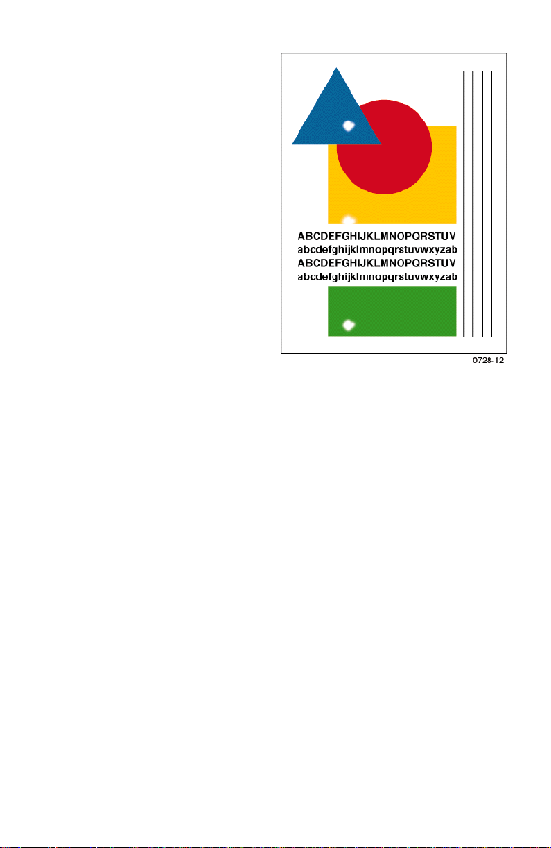
Repeating defect or voids on print
This can usually be traced to a
dent-like defect in the developer
roller of the imaging drum unit in
question. Measure the spacing
between the spots. The distance
between the repeating spots
indicates the source of the problem.
In some instances, the spots may be
dark instead of white. They may
also be shaped something other
than round.
■ If the spots are about 143 mm
(5.6 in.) apart, then the problem
is a defect on a fusers heat
roller. Replace the fuser.
■ If the spots are about 113 mm
(4.4 in.) apart, then the problem
is a defect on a fusers pressure
roller. Replace the fuser.
■ If the spots are 58 mm
(2.3 in.) the problem is with the
transfer roller of the transfer
belt unit. Replace the transfer
belt unit.
■ 94 mm (3.7 in.): Imaging drum. Replace the imaging drum unit.
■ 50 mm (2.0 in.): Developing roller. Replace the imaging drum unit of
the affected color.
■ 44 mm (1.7 in.): Charging roller. Replace the imaging drum unit of the
affected color.
■ 68 mm (2.7 in.): Toner supply roller. Replace the imaging drum unit of
the affected color.
Service Guide 53
Page 67

Missing characters or voids in print
1. Look for dirt or contamination
on the LED heads. Clean them
with a clean, alcohol-soaked,
lint-free wipe.
2. Inspect and clean the imaging
drum unit’s power terminals
Ensure the spring-loaded pins
travel smoothly up and down.
3. Is a low-toner condition
occurring?
4. Replace any imaging drum
units you suspect are defective.
5. Are the LED heads’ ribbon
cables undamaged and
properly seated?
6. Is +3.8V (red wire) supplied to
Pin 3 of each LED head
assembly? If yes, replace the
LED head assembly.
7. Is +3.8 V supplied to the
POWER connector pins 1, 2, 3,
4, 5, 6, 7 and 8 on the junction board or at the 16-pin interconnect near the
top cover hinge (under the top shield plate). Inspect the junction board’s
wiring connectors. If the voltage is not OK, replace the low-voltage power
supply.
8. If +32 volts supplied to the POWER connector pins 7, 8, 9 and 10 on the
engine controller board? Inspect the wiring harnesses or replace the
low-voltage power supply.
9. Is +32V supplied to the HVOLT connector Pin 5 of the engine board. If not
replace the engine controller board. Transfer the old engine controller
board’s EEPROM (lower-right corner of boar d) to the new engine contr oller
board.
10. Inspect the high-voltage wiring harnesses.
11. Replace the high voltage power supply.
54 Phaser 2135 Color Printer
Page 68

Color misalignments
1. Test the registration sensor as
described in the topic “Switch
scan test” on page 63. Ensure
the registration sensors are
clean without toner dust on
them. Also test the registration
solenoid, as described in the
topic “Motor and clutch tests”
on page 69, to ensure the
registration shutter operates
smoothly and closes complely,
allowing no toner to fall on the
senors.
2. Look for any broken gears in
the printer. specifically, inspect
the imaging drum gear
assembly, the paper feeder
assembly and the transfer belt
assembly.
3. Inspect and clean the imaging
drum unit’s power terminals
Ensure the spring-loaded pins
travel smoothly up and down.
4. Replace any imaging drum units you suspect are defective.
5. Are the LED heads’ ribbon cables undamaged and properly seated?
Replace any suspect LED head assembly, if necessary
6. Inspect the wiring harnesses of the junction board for damage or improper
seating.
7. Inspect the wiring harnesses of the engine controller board for damage or
improper seating.
8. Replace the engine controller board. Transfer the old engine controller
board’s EEPROM (lower-right corner of boar d) to the new engine contr oller
board.
Service Guide 55
Page 69

Unexpected colors
The colors produced by the printer are dramatically different from the color you
expected.
1. Look for dirt or contamination
on the LED heads. Clean them
with a clean, alcohol-soaked,
lint-free wipe.
2. If it appears that a single
primary color is missing, check
that imaging drum’s toner
cartridge to see if it is empty;
the toner sensor board may not
be detecting the empty sensor.
3. Inspect and clean the imaging
drum unit’s power terminals
Ensure the spring-loaded pins
travel smoothly up and down.
4. Replace any imaging drum
units you suspect are defective.
5. Are the LED heads wiring
harnesses undamaged and
properly seated?
6. Is +3.8V (red wire) supplied to
Pin 3 of each LED head
assembly? If yes, replace the
LED head assembly.
7. Is +3.8 V supplied to the POWER connector pins 1, 2, 3, 4, 5, 6, 7 and 8 on
the junction board or at the 16-pin interconnect near the top cover hinge
(under the top shield plate). Inspect the junction board’s wiring connectors.
If the voltage is not OK, replace the low-voltage power supply.
8. If +32 volts supplied to the POWER connector pins 7, 8, 9 and 10 on the
engine controller board? Inspect the wiring harnesses or replace the
low-voltage power supply.
9. Is +32V supplied to the HVOLT connector Pin 5 of the engine board. If not
replace the engine controller board. Transfer the old engine controller
board’s EEPROM (lower-right corner of boar d) to the new engine contr oller
board.
10. Inspect the high-voltage wiring harnesses.
11. Replace the high voltage power supply.
56 Phaser 2135 Color Printer
Page 70

Image is skewed on the paper
1. Is the paper in good condition and the recommended type and weight for a
laser printer? Does the paper in the multi-sheet bypass feeder match the
front panel settings?
2. Is the printer printing within its environmental specifications? Print the
Diagnostic Summary Page to determine the printer’s conditions.
3. Ensure the tray is properly loaded with the tray’s paper guides correctly
snugged against the stack of paper.
4. Swap the tray from which the skewed print originates.
5. Ensure that paper feed rollers are clean and undamaged. Clean them with
a clean, dry, lint-free cloth if debris is visible. Inspect the paper pick roller.
6. Replace the paper pick rollers.
7. Look for obstructions in the paper path.
8. Clean the intermediate and aligning rollers. Clean them with a clean, dry,
lint-free cloth if debris is visible.
9. Replace the paper feeder.
Image is not centered on the print
1. Is the paper in good condition and appropriate for a laser printer?
2. Is the printer printing within its environmental specifications? Print the
Diagnostic Summary Page to determine the printer’s conditions.
3. Ensure that paper feed rollers are clean and undamaged. Clean them with a
clean, dry, lint-free cloth if debris is visible. Inspect its paper pick roller.
Look for obstructions in the paper path.
4. Clean the feed rollers and the registration rollers with a clean, lint-free wipe.
5. Use the margin adjust function found in the front panel Support Menu /
Margin Adjust.
6. Replace the engine controller board.
The print is wrinkled
1. Check for an obstruction in the paper path, particularly with the feed rollers
and the fuser.
2. Is the paper in good condition and appropriate size, weight, grain and
grade for a laser printer? Print the Diagnostic Summary Page to determine
the printer’s conditions.
3. Is the printer printing within its environmental specifications?
4. If possible, you should feed long-grain paper into the printer. Long-grained
paper's grain is parallel to the paper path (the direction the paper travels
while it is fed through the printer). Rotate A-, A4- and B5-size paper for
short-edge feed to see if it makes a difference.
Service Guide 57
Page 71

Macintosh printing problems
Image never prints
The printer indicates it is receiving data, but no print comes out of printer or the
printer goes back to Ready to Print mode without printing an image.
1. Make sure that the correct printer icon was selected in the Chooser. Try
printing the job again. Try printing a different file or from a different
application.
2. In the Chooser, switch background printing off. Try printing the job
again. With newer LaserWriter printer drivers, select Foreground
Printing in the Print dialog box.
3. Download the Echo showpage snippet which produces a blank sheet of
paper, to determine if the printer is receiving and processing files.
4. Make sure you are printing with the correct PPD file.
5. Activate Error Handler using the front panel Advanced Printer
Settings menu. Alternately, download the Error Handler utility and
try printing the job again. If an error page is printed after printing the
job again, call the Customer Support Hotline for further assistance.
Please have the error page in hand.
6. If available, try printing to a black-and-white PostScript Level 2 printer
(such as an Apple LaserWriter). If the file does not print on the
black-and-white PostScript printer, this may mean that the problem is
application- or network-related.
Image is rotated 90 degrees
1. In the application's Page Setup, make sure that the image is selected to
print in Portrait or Landscape orientation, as you expect.
Image prints in black-and-white
1. In the Chooser, ensure a color printer icon is displayed next to the
Phaser 2135 in the list of available printers. This indicates the printer’s
PPD has been selected and properly configured.
2. In the Print dialog box, make sure that the Color/Grayscale option has
been selected.
3. Make sure that the Phaser 2135 printer icon was selected in the
Chooser. Try printing the job again.
4. Check the version of your LaserWriter driver to ensur e that it is version
8.0.x or higher. Earlier versions of the driver do not support color
PostScript.
5. The application may require special instructions to print, such as those
contained in a PPD file; check in the Phaser 12135 Printer CD-ROM.
58 Phaser 2135 Color Printer
Page 72

Printer isn’t in the Chooser
1. Ensure that the printer is turned on and the printer is in its READY
mode.
2. Check the Network or AppleTalk control panel to ensure the proper
network or zone is selected.
3. Power-cycle the printer.
4. Check to see if the printer has not been renamed or placed in another
zone. You can print a Configuration Page, which lists this EtherTalk
information as well as other information about the printer.
5. Verify the EtherTalk settings on the printer’s Configuration Page.
6. Verify that the printer is correctly cabled to the network and that the
Ethernet cable functions properly.
7. Locate and remove and Windows NT shared printers that have
captured the AppleTalk queue for the printer.
8. Verify the driver version for the built-in Ethernet port on a Macintosh
G3.
9. Reset the printer’s NVRAM settings.
10. Disable QuickDraw GX
Windows printing problems
Image never prints
The printer’s front panel Receiving data message is displayed as if receiving
data, but nothing comes out of printer or the printer goes back to Ready to
Print mode without printing an image.
1. From the printer driver, under the printer's set up options, set
TRANSMISSION RETRY = 850.
Service Guide 59
Page 73

Service Tests and Adjustments
Starting the diagnostics mode
To start the engine maintenance mode:
1.
Turn off the printer.
2.
Press and hold the
3.
Turn on the printer.
Menu (1)
and
Enter (4)
keys.
4.
5.
6.
7.
Use engine maintenance mode to test the printer sensors, test the media transport
system, test the imaging LED banks, and to reset NVRAM.
To exit engine maintenance mode, while
press
then turn power back on.
DIAGNOSTIC MODE xx.xx.xx
When,
xx.xx.xx
(
Press the
Press the
Press the
Press the
Online (0)
is the ROM version), release the control panel keys.
Menu (1)
Item (2) or (6)
Value (3)
Value (7)
key to enter the maintenance mode menu.
key to activate the displayed menu item.
key to discontinue a test in progress.
. Alternately, you can turn the power off, wait a few seconds, and
is displayed on the control panel
keys to scroll through the menu.
DIAGNOSTIC MODE xx.xx
is displayed,
Service Guide
61
Page 74

These are the items of the engine maintenance mode menu.
Switch Scan Test
■
Motor & Clutch Tests
■
Test Print
■
Consumables count reset
■
Consumable Status
■
Printer Status
■
This table details the menu items, their sub-menus, and settings.
Engine maintenance mode menu
Menu -
scroll
using Menu(1) or
Menu(5)
SWITCH SCAN SCAN00 thru
MOTOR &
CLUTCH TEST
TEST PRINT Items set for test
NV-RAM INITIAL
(consumables
count reset)
CONSUMABLE
STATUS
PRINTER
STATUS
Items -
scroll
using
Item(2) or Item(6)
SCAN19
Lists each motor
and clutch
print
TABLE 1
TABLE 2
TABLE 3
Displays each
consumable item
Lists print count
and impressions
made by each
imaging unit
Settings -
using
Value(3] or Value(7)
Test start/stop Select and test printer
Test start/stop
Alternation of setting
or T est start/stop
Select parameters of
print such as paper
source and print
mode. Test start/stop
Test start/stop Table 1 determines the
no settings
no settings
scroll
Description
switches and sensors
Test the printer motors and
clutches. A selected motor or
clutch is operated for 10
seconds
Test the print engine’s ability
to print
counter values initialized after
exchanging the drum belt
unit, fuser unit or toner
cartridge. The adjusted
values for mechanical
controls are all cleared to
their initial values.
use Table 2 or Table 3.
The consumption status of
each consumables is
displayed in turn. Values
show are of prints made and
percentage of toner
consumed.
The life status of the selected
consumable is displayed.
Do not
62
Phaser 2135 Color Printer
Page 75
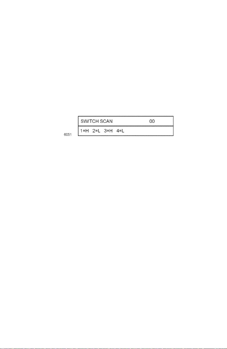
Switch scan test
Use this test to check the operation of the printer’s switches and sensors.
1.
Enter the diagnosis mode by pressing and holding the
Enter (4)
2.
Press the
SCAN
3.
Press the
SWITCH SCAN tests. The table below list the SCAN test items and
which sensors and switches and test by that menu item.
4.
Pressing the
test. The SWITCH SCAN number begins to blink, and the
corresponding logic state (High or Low) of the particular switches or
sensors scanned by the test (listed as 1=, 2=, 3=, and 4=) are displayed.
5.
With a test active, you can manually actuate the sensors being scanned
and look for a change at the control panel.
6.
Press
7.
Repeat steps 2 through 5 as required.
8.
To exit the switch scan test mode, press
keys as you turn on the printer.
Menu (1, 5)
appears on the upper display.
Item (2,6)
Value (3)
Value (7)
keys to scroll through the list of test until
keys to scroll through the list of sensor tests, called
key activates the currently displayed switch scan
to stop the current test.
Enter (4)
.
Menu (1)
SWITCH
and
Service Guide
63
Page 76

Face-down paper eject sensor
Face-down sensor
Paper eject sensor
Heat roller
Driving roller
Paper eject roller
Stacker full sensor
C drum
K drumY drumM drum
Entrance belt sensor
MT feed roller
Pinch roller 2
Backup roller
Duplex-in sensor
Duplex roller
Duplex rear sensor
Carrier belt
Duplex front sensor
Duplex feed roller
Driving roller
Belt cleaning blade
Switch scans and the sensor and switches test
Switch or sensor Switch scan test Test result Details
Tray 1 No Paper
Sensor
Tray 1 Low Paper
Sensor
Cassette
Entrance
Manual Bypass
Feeder Entrance
sensor
Belt Entrance Switch Scan 011=L - Paper present
Exit Sensor Switch Scan 012=L - No paper
Stack Full Sensor Switch Scan 013=L - Stack full
not used
Black Toner
Cartridge Present
Cyan Toner
Cartridge Present
Magenta T oner
Cartridge Present
Switch Scan 001=L - Paper present
H - No paper
Switch Scan 002=L - Paper level OK
H - Low paper
Switch Scan 003=L - Paper present
H - No paper
Switch Scan 004=L - Paper present
H - No paper
H - No paper
H - Paper present
H - No paper
Switch Scan 01
4=
Switch Scan 021=L - Deactuated
H - Unit installed
Switch Scan 022=L - Deactuated
H - Unit installed
Switch Scan 023=L - Deactuated
H - Unit installed
Pull main tray out to test sensor
Pull main tray out to test sensor
Open right-side door and toggle sensor
flag below the feed rollers
Open right-side door and push sheet of
paper into paper path leading to the
transfer unit
Open right-side door and push sheet of
paper into paper path leading to the
transfer unit. Open the top cover and
manually rotate the registration roller
(use the green thumbwheel on the left
end of the roller) to feed the paper to the
transfer belt.
Toggle sensor flag behind the fuser.
Remove the fuser, if necessary
Toggle the sensor flag at the exit bin
not used
Open top cover and pull down the
sensor flag next to rear of the LED head.
Open top cover and pull down the
sensor flag next to rear of the LED head.
Open top cover and pull down the
sensor flag next to rear of the LED head.
Registration roller B
Entrance MT sensor
1st feed roller
2nd feed roller
Registration roller A
Entrance cassette sensor
Auxiliary roller
Carrier sensor
Pinch roller 1
0725-75
64
Phaser 2135 Color Printer
Page 77

Switch scans and the sensor and switches test
Switch or sensor Switch scan test Test result Details
Yellow Toner
Cartridge Present
Top Cover Switch Switch Scan 031=L - Top closed
Right Cover
Switch (Door A)
Waste Toner
Sensor
not used
not used
not used
Manual Bypass
Feeder Home
Sensor
Manual Bypass
Feeder Paper
Empty Switch
not used
Manual Bypass
Feeder OHP
Sensor
Tray 1, Size 1
Switch - (Top)
Tray 1, Size 2
Switch
Tray 1, Size 3
Switch
Tray 1, Size 4
Switch - (Bottom)
Color Registration
(Front) - 006
Color Registration
(Rear) - 00A
not used
not used
Upper Fuser
Thermistor - 00D
not used
Switch Scan 024=L - Deactuated
H - Unit installed
H - Top opened
Switch Scan 032=L - Cover closed
H - Cover opened
Switch Scan 033=L - Not full
H - Full
Switch Scan 03
4=
Switch Scan 04
Switch Scan 05
Switch Scan 061=L - Roller at home
H - Roller not
home
Switch Scan 062=L - Paper loaded
H - No Paper
Switch Scan 06
3=
Switch Scan 064=L - Transparency
H - Paper
Switch Scan 071=L - Actuated
H - Deactuated
Switch Scan 072=L - Actuated
H - Deactuated
Switch Scan 073=L - Actuated
H - Deactuated
Switch Scan 074=L - Actuated
H - Deactuated
Switch Scan 081=Density Value
***H
Switch Scan 082=Density Value
***H
Switch Scan 08
3=
Switch Scan 08
4=
Switch Scan 091=Encoded fuser
roller temperature
Switch Scan 09
2=
Open top cover and pull down the
sensor flag next to rear of the LED head.
Open top cover
Open right-side door
Remove the drum units and the transfer
belt. Locate the optical sensor in a hole
below the registration rollers. Interrupt
the sensor by inserting a scrap of paper
not used
not used
not used
Open the top cover and remove the
drum units. Manually rotate the manual
bypass feed roller by turning the white
gear on the right end of the registration
roller.
Toggle the switch located at the
inner-base of the Manual Bypass Feeder
tray next to the pick pad
not used
Manually feed a sheet of paper thru the
feeder by rotating the registration roller.
Transparency film causes no change
Remove the tra y and actuate the sensor
flags at the rear of the tray cavity
Color value in hexidecimal format. The
default is between 000 to 060 when the
sensors are exposed to light. Manually
open the registration shutter to expose
the sensors to light. If the sensor
reading is too high, clean any toner dust
off the sensor lens and test again.
not used
not used
Temperature is encoded as a
hexidecimal value. The default is
between 001 and 0D4.
not used
Service Guide
65
Page 78

Switch scans and the sensor and switches test
Switch or sensor Switch scan test Test result Details
Lower Fuser
Thermistor - 00F
not used
Humidity Sensor Switch Scan 101=Encoded
Temperature
Sensor
not used
not used
Duplex In Sensor Switch Scan 111=L - Deactuated
Duplex Rear
Sensor
not used
Switch Scan 093=Encoded fuser
roller temperature
Switch Scan 09
4=
environmental
humidity
Switch Scan 102=Encoded
environmental
temperature
Switch Scan 10
3=
Switch Scan 10
4=
H - Paper present
Switch Scan 112=L - Deactuated
H - Paper present
Switch Scan 113=not used
Temperature is encoded as a
hexidecimal value. The default is
between 001 and0 D4.
not used
Ambient environmental humidity is
encoded as a hexidecimal value. The
default is between 158 and 2A7.
Ambient environmental temperature is
encoded as a hexidecimal value. The
default is between 0E7 and 27C.
not used
not used
Pull out the duplex unit. Lift its cover.
Place a sheet of paper inside on the
sensor flag. Close the cover. Reinsert
the duplex unit in the printer.
Pull out the duplex unit. Lift its cover.
Place a sheet of paper inside on the
sensor flag. Close the cover. Reinsert
the duplex unit in the printer.
Duplex Front
Sensor
Tray 2, Size 1
Switch - (Top)
Tray 2, Size 2
Switch
Tray 2, Size 3
Switch
Tray 2, Size 4
Switch - (Bottom)
Tray 2 No Paper
Sensor
Tray 2 Low Paper
Sensor
not used
not used
Right Door Tray 2 Switch Scan 141=L - Opened
not used
Tray 2 Feed
Sensor
not used
Switch Scan 114=L - Deactuated
H - Paper present
Switch Scan 121=L - Actuated
H - Deactuated
Switch Scan 122=L - Actuated
H - Deactuated
Switch Scan 123=L - Actuated
H - Deactuated
Switch Scan 124=L - Actuated
H - Deactuated
Switch Scan 131=L - Paper present
H - No paper
Switch Scan 132=L - Paper level OK
H - Low paper
Switch Scan 133=not used
Switch Scan 134=not used
H - Closed
Switch Scan 142=not used
Switch Scan 143=L - Actuated
H - Deactuated
Switch Scan 144=not used
Pull out the duplex unit. Lift its cover.
Place a sheet of paper inside on the
sensor flag. Close the cover. Reinsert
the duplex unit in the printer.
Remove the tra y and actuate the sensor
flags at the rear of the tray cavity
Pull tray out to test sensor
Pull tray out to test sensor
Open door to test sensor
Open the Tray 2 right-side door and
toggle sensor flag below the feed rollers
66
Phaser 2135 Color Printer
Page 79

Switch scans and the sensor and switches test
Switch or sensor Switch scan test Test result Details
Tray 3, Size 1
Switch - (Top)
Tray 3, Size 2
Switch
Tray 3, Size 3
Switch
Tray 3, Size 4
Switch - (Bottom)
Tray 3 No Paper
Sensor
Tray 3 Low Paper
Sensor
not used
Switch Scan 151=L - Actuated
H - Deactuated
Switch Scan 152=L - Actuated
H - Deactuated
Switch Scan 153=L - Actuated
H - Deactuated
Switch Scan 154=L - Actuated
H - Deactuated
Switch Scan 161=L - Paper present
H - No paper
Switch Scan 162=L - Paper level OK
H - Low paper
Switch Scan 163=not used
Remove the tra y and actuate the sensor
flags at the rear of the tray cavity
Pull tray out to test sensor
Pull tray out to test sensor
not used
Right Door Tray 3 Switch Scan 17
not used
Tray 3 Feed
Sensor
not used
Tray 4, Size 1
Switch - (Top)
Tray 4, Size 2
Switch
Tray 4, Size 3
Switch
Tray 4, Size 4
Switch - (Bottom)
Tray 4 No Paper
Sensor
Tray 4 Low Paper
Sensor
not used
not used
Right Door Tray 4 Switch Scan 201=L - Opened
not used
Switch Scan 164=not used
1=
Switch Scan 172=not used
Switch Scan 173=L - Actuated
Switch Scan 174=not used
Switch Scan 181=L - Actuated
Switch Scan 182=L - Actuated
Switch Scan 183=L - Actuated
Switch Scan 184=L - Actuated
Switch Scan 191=L - Paper present
Switch Scan 192=L - Paper level OK
Switch Scan 193=not used
Switch Scan 194=not used
Switch Scan 202=not used
L - Opened
H - Closed
H - Deactuated
H - Deactuated
H - Deactuated
H - Deactuated
H - Deactuated
H - No paper
H - Low paper
H - Closed
Open door to test sensor
Open the Tray 3 right-side door and
toggle sensor flag below the feed rollers
Remove the tra y and actuate the sensor
flags at the rear of the tray cavity
Pull tray out to test sensor
Pull tray out to test sensor
Open door to test sensor
Tray 4 Feed
Sensor
not used
Switch Scan 203=L - Actuated
H - Deactuated
Switch Scan 204=not used
Open the Tray 4 right-side door and
toggle sensor flag below the feed rollers
Service Guide
67
Page 80

Switch scans and the sensor and switches test
Switch or sensor Switch scan test Test result Details
Tray 5, Size 1
Switch - (Top)
Tray 5, Size 2
Switch
Tray 5, Size 3
Switch
Tray 5, Size 4
Switch - (Bottom)
Tray 5 No Paper
Sensor
Tray 5 Low Paper
Sensor
not used
Switch Scan 211=L - Actuated
H - Deactuated
Switch Scan 212=L - Actuated
H - Deactuated
Switch Scan 213=L - Actuated
H - Deactuated
Switch Scan 214=L - Actuated
H - Deactuated
Switch Scan 221=L - Paper present
H - No paper
Switch Scan 222=L - Paper level OK
H - Low paper
Switch Scan 223=not used
Remove the tra y and actuate the sensor
flags at the rear of the tray cavity
Pull tray out to test sensor
Pull tray out to test sensor
not used
Right Door Tray 5 Switch Scan 23
not used
not used
not used
Black LED Head
temperature
Yellow LED Head
temperature
Magenta LED
Head temperature
Cyan LED Head
temperature
Black Imaging
Drum Contact
Cyan Imaging
Drum Contact
Magenta Imaging
Drum Contact
Yellow Imaging
Drum Contact
Switch Scan 224=not used
1=
Switch Scan 232=not used
Switch Scan 233=not used
Switch Scan 234=not used
Switch Scan 241=Encoded head
Switch Scan 242=Encoded head
Switch Scan 243=Encoded head
Switch Scan 244=Encoded head
Switch Scan 251=L - Installed
Switch Scan 252=L - Installed
Switch Scan 253=L - Installed
Switch Scan 254=L - Installed
L - Opened
H - Closed
temperature
temperature
temperature
temperature
H - Missing
H - Missing
H - Missing
H - Missing
Open door to test sensor
Temperature is encoded as a
hexidecimal value. The default is
between 083 and 316.
T ests the imaging drum up/down sensor .
Remove drum unit to test.
68
Phaser 2135 Color Printer
Page 81

Motor and clutch tests
1.
Enter the diagnosis mode by pressing and holding the
Enter (4)
keys as you turn on the printer.
Menu (1)
and
2.
Press the
& CLUTCH TEST
Caution
3.
Press the
clutches until the desired item is displayed.
4.
If indicated, remove the consumable items constraining the test.
5.
Press the
item blinks, and the selected motor or clutch is driven for 10 seconds.
6.
Press the
Menu (1, 5)
Before running some motor and clutch tests you must remove
certain printer consumable items; refer to table below. The front
panel also reminds you to remove the necessary item before
starting the test.
Item (2, 6)
Value (3)
Value (7) key to stop the unit.
keys to scroll through the list of test until
appears on the upper display.
keys to scroll through the list of motors and
key to start the displayed test. The displayed test
7. Repeat the Steps 2 to 7 for other motor or clutch tests.
8. Press Enter (4) ends the tests.
MOTOR
Service Guide
69
Page 82

Motor and clutch test constraints
Constraints
Motor or clutch displayed
on control panel
BLACK-ID MOTOR REMOVE ID Run test with the drum units removed.
YELLOW-ID MOTOR REMOVE ID Run test with the drum units removed.
MAGENTA-ID MOTOR REMOVE ID Run test with the drum units removed.
CYAN-ID MOTOR REMOVE ID Run test with the drum units removed.
TRANSFER BELT MOTOR REMOVE ID Run test with the drum units removed.
FUSER MOTOR none Remove the fuser and observe the fuser
REGISTRATION MOTOR Remove media
REGISTRATION CLUTCH none Open the front cover and observe
FRONT MOTOR
(REGISTRATION MOTOR)
REGISTRATION SHUTTER none Remove the imaging drums and the
EXIT SOLENOID none Open the top cover and observe the exit
FACEDOWN SOLENOID none Open the face-up tray and observe the
DUPLEX MOTOR none Listen for the motor turning for about 5
DUPLEX REAR CLUTCH none Listen for the clutch activating
DUPLEX FRONT CLUTCH none Listen for the clutch activating
TRAY 1 MOTOR
(FEED MOTOR)
TRAY 2 MOTOR
(FEED MOTOR)
displayed on
control panel Details
Observe the imaging drum drive gear rotate
Observe the imaging drum drive gear rotate
Observe the imaging drum drive gear rotate
Observe the imaging drum drive gear rotate
drive gears turn.
Remove the imaging drums and observe
from the
multi-sheet bypass
feeder
Remove media
from the
multi-sheet bypass
feeder
EXIT TRA Y1
CASSETTE
EXIT TRA Y2
CASSETTE
the registration roller B rotate
registration roller A turning
Open the multi-sheet bypass feeder and
observe the paper position plate cycle up
and down
transfer belt to watch the shutter open
and close smoothly and completely.
gate move up and down
facedown gate move up and down
seconds
Run the test with Tray 1 removed.
Observe the pick roller rotate as the
motor runs
Run the test with Tray 2 removed.
Observe the pick roller rotate as the
motor runs
70 Phaser 2135 Color Printer
Page 83

Motor and clutch test constraints
Constraints
Motor or clutch displayed
on control panel
TRAY 3 MOTOR
(FEED MOTOR)
TRAY 4 MOTOR
(FEED MOTOR)
TRAY 5 MOTOR
(FEED MOTOR)
TRAY 1 HOPPING CLUTCH none Remove Tray 1 and listen for the clutch
TRAY 2 HOPPING CLUTCH
(OPTIONAL)
TRAY 3 HOPPING CLUTCH
(OPTIONAL)
TRAY 4 HOPPING CLUTCH
(OPTIONAL)
TRAY 5 HOPPING CLUTCH
(OPTIONAL)
FEED ROLLER 1 CLUTCH none Remove Tray 1 and listen for the clutch
FEED ROLLER 2 CLUTCH
(OPTIONAL) -
FEED ROLLER 3 CLUTCH
(OPTIONAL)
FEED ROLLER 4 CLUTCH
(OPTIONAL)
FEED ROLLER 5 CLUTCH
(OPTIONAL)
ID UP/DOWN Raises and lowers the imaging drum units
FAN1 TEST Chassis fan, runs for 10 seconds
FAN2 TEST Fuser fan, runs for 10 seconds
TRAY 1 LIFT MOTOR EXIT TRAY1
TRAY 2 LIFT MOTOR
(OPTIONAL)
TRAY 3 LIFT MOTOR
(OPTIONAL)
TRAY 4 LIFT MOTOR
(OPTIONAL)
displayed on
control panel Details
EXIT TRA Y3
CASSETTE
EXIT TRA Y4
CASSETTE
EXIT TRA Y5
CASSETTE
none Remove Tray 2 and listen for the clutch
none Remove Tray 3 and listen for the clutch
none Remove Tray 4 and listen for the clutch
none Remove Tray 5 and listen for the clutch
none Remove Tray 2 and listen for the clutch
none Remove Tray 3 and listen for the clutch
none Remove Tray 4 and listen for the clutch
none Remove Tray 5 and listen for the clutch
CASSETTE
EXIT TRA Y2
CASSETTE
EXIT TRA Y3
CASSETTE
EXIT TRA Y4
CASSETTE
Run the test with Tray 3 removed.
Observe the pick roller rotate as the
motor runs
Run the test with Tray 4 removed.
Observe the pick roller rotate as the
motor runs
Run the test with Tray 5 removed.
Observe the pick roller rotate
Run the test with Tray 1 removed. This
test activates the tray 1’ s lift motor. Watch
it raise the l paper lift plate
Run the test with Tray 2 removed. This
test activates the tray 2’ s lift motor. Watch
it raise the l paper lift plate
Run the test with Tray 3 removed. This
test activates the tray 3’ s lift motor. Watch
it raise the l paper lift plate
Run the test with Tray 4 removed. This
test activates the tray 4’ s lift motor. Watch
it raise the l paper lift plate
Service Guide 71
Page 84

Test printing
1. Enter the diagnosis mode by pressing and holding the Menu (1) and
Enter (4) keys as you turn on the printer.
2. Press the Menu (1, 5) keys to scroll through the list of test until TEST
appears on the upper display.
PRINT
3. Press the Item (2, 6) keys to scroll through the list of test print items
until the desired print option is displayed.
4. With a test print menu item displayed, press the Value (3, 7) keys to
scroll through the printing options of that item, such as which tray to
print from and to print in blank-and-white or color.
Test Print menu
Display Set Value Function
PRINT
EXECUTE
TEST
PATTERN
CASSETTE TRAY1 Lets you select the source of paper for the test print.
PAGE XXXX Set number of print you wish the printer to print, 0000 mean
COLOR ON Lets you select between color or monochrome printing
DUPLEX ON Lets you select between single-sided or double-sided printing.
- Press Value (3) to start printing. Press Value (7) to stop printing.
1 Selection of Printing Patterns
2
3
4
5
6
7 - 14
TRAY2
TRAY3
FF
NONE
OFF
OFF
1: LED Head Drive Pattern
2: Color Registration Adjust Pattern
3: Reserved
4: Gray pattern
5: Thin lines
6: Colored stripes
7 thru 14: Do not use
continuous printing.
5. Press the Item (2, 6) keys to scroll to the menu item PRINT EXECUTE.
Press Value (3) to starts printing.
6. Press Value (7) to stop printing.
72 Phaser 2135 Color Printer
Page 85

The following messages are showing at warm-up and during printing.
P: Number of sheets printed for test (in units of sheets)
U: Upper fuser heater temperature measurement (in degrees Celsius)
L: Lower fuser heater temperature measurement (in degrees Celsius)
T: Environmental temperature measurement (in degrees Celsius)
H: Environmental humidity measurement (in units of%). The key
Value (3) changes the display.
7. Press Enter (4) to end the test.
Service Guide 73
Page 86

Consumable count initialization
This test menu item allows you to initialize the print engine’s consumable counts
and registration set points.
1. Enter the diagnosis mode by pressing and holding the Menu (1) and
Enter (4) keys as you turn on the printer.
2. Press the Menu (1, 5) keys to scroll through the list of test until NV-RAM
appears on the upper display.
INITIAL
3. Press the Item (2, 6) keys to select Table 1. The table indicates which
NVRAM items will be initialized. Refer to the table printed below.
4. Press and hold Value (3) for 10 seconds to initialize the items of the
selected table. The front panel display
times.
5. Press Enter (4) to exit the test mode.
Table 1: Initialization items - consumables
Initialization
Item Detail
NV-RAM INITIAL blinks eight
Drum Counter
Black
Yellow
Magenta
Cyan
Belt Unit
Counter
Fuser Unit
Counter
Toner Counter
Black
Yellow
Magenta
Cyan
Initializes the drum counter’s count
after the replacement of a drum.
Initializes the print count after the
replacement of a transfer belt unit.
Initializes the fuser’s print count after
the replacement of a fuser unit.
Initializes the toner use count after a
toner cartridge is replaced
74 Phaser 2135 Color Printer
Page 87

Consumable counter display
This test indicate the status of each consumable supply.
1. Enter the diagnosis mode by pressing and holding the Menu (1) and
Enter (4) keys as you turn on the printer.
2. Press the Menu (1, 5) keys to scroll through the list of test until
CONSUMABLE STATUS appears on the upper display.
3. Press the Item (2, 6) keys to scroll through the list of consumable supply
items. The consumption value is displayed with the item. The table
below lists the menu items.
4. Press Enter (4) to end the test.
Consumable counter menu items
Upper Display Lower Display Detail
FUSER UNIT ********IMAGES Shows the number of sheets printed since
installation of a new fuser unit.
TR BELT UNIT ********IMAGES Shows the number of images printed since
installation of a new transfer belt unit.
BLACK ID UNIT ********IMAGES Indicates the number of images processed by
YELLOW ID UNIT ********IMAGES
MAGENTA ID UNIT ********IMAGES
CYAN ID UNIT ********IMAGES
BLACK TONER ***% Shows the amount of toner consumed from each
YELLOW TONER ***%
MAGENTA TONER ***%
CY AN T ONER ***%
each imaging drum unit since it was installed.
toner cartridge.
Service Guide 75
Page 88

Consumable continuation counter display
The self-diagnosis is carried out to indicate the consumption status of each
consumable supply.
1. Enter the diagnosis mode by pressing and holding the Menu (1) and
Enter (4) keys as you turn on the printer.
2. Press the Menu (1, 5) keys to scroll through the list of test until
PRINTER STATUS appears on the upper display.
3. Press the Item (2, 6) keys to scroll through the list of supply items. The
life-cycle consumption value is displayed with the item. The table
below lists the menu items.
1. Press Enter (4) to end the test.
Consumable life-cycle counts
Upper Display Lower Display Unit Detail
TOTAL SHEETS
FED
BLACK
IMPRESSIONS
YELLOW
IMPRESSIONS
MAGENTA
IMPRESSIONS
CYAN
IMPRESSIONS
******** PRINTS Prints Indicates the total number of sheets fed
including blank paper
******** IMAGES Image Displays the number of images printed
by each imaging drum
******** IMAGES Image
******** IMAGES Image
******** IMAGES Image
76 Phaser 2135 Color Printer
Page 89
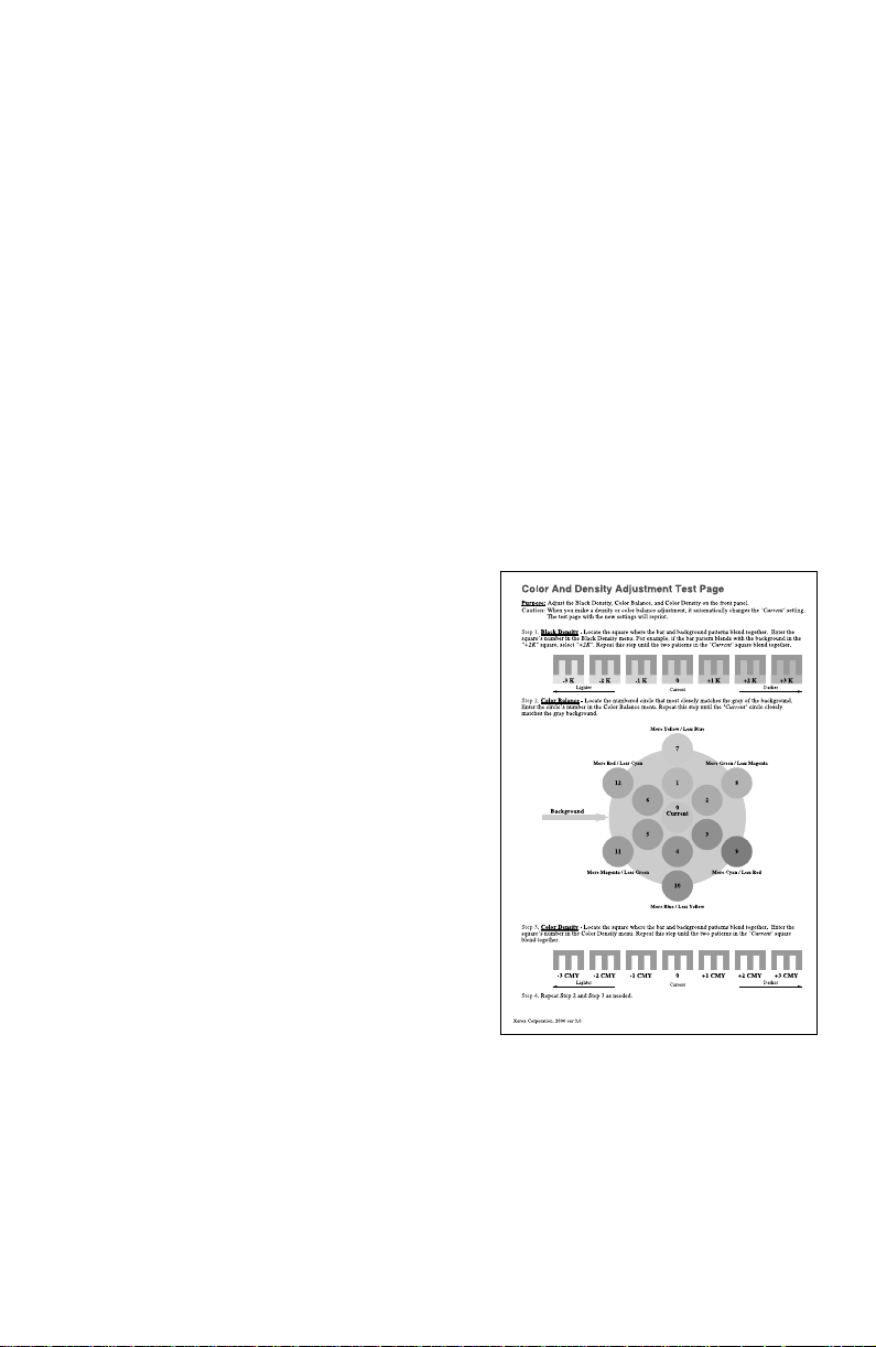
Adjusting color density and balance
Over the life of the printer, colors may change. For example, reds may begin to
take on a purple cast, or blues may take on a green cast. This happens during the
normal use of a color printer and can be easily remedied by using the color
adjustment procedure described in this section
This front panel procedure involves printing a test page and adjusting the
densities and colors based on the appearance of the test page. You may need to
repeat this procedure and test your adjustments until you achieve the desired
effect.
Note At any time, you can reset the printer to the factory defaults by
selecting Color Defaults from the Color Adjust Menu.
Printing a Test Page
1. Press the Menu (1, 5) keys until you see Color Adjust.
2. Press Item (2, 6) keys and the printer prints the Color Balance test print.
Interpreting the Color Balance test print
The Color Balance test print contains
numbered images and disks that indicate
possible adjustments that can be made. You
can choose to make an adjustment to the
Black Density, the Color Balance, or the
Color Density.
■ The Black Density Images, numbered
-3K...0,...+3K, show a
lightness/darkness range using black
only.
■ The Color Balance Images, numbered
0,1,2,...12, show variations of
three-color gray. Each of these circles
contains gray with tints of other colors.
■ The Color Density Images, numbered
-3CMY...0,...+3CMY, show a
lightness/darkness range using three
colors (cyan, magenta, yellow).
Service Guide 77
Page 90

What to look for
There are three things to look for in examining the test print.
■ The correct Black Density is determined by selecting the image in which
the foreground and background grays most closely match.
■ The correct Color Balance is determined by matching the “Current”
disk in the center with the gray background. The background is
produced using black only and the circles are produced using a
combination of cyan, magenta, and yellow.
■ The correct Color Density is determined by selecting the image in
which the foreground and background gray patterns most closely
match.
Making adjustments
Use the following procedures to make adjustments to the color density and
balance:
Black density adjustment
Press Item (2, 6) keys until you see Color Adjust Menu: Black Density.
1.
2. Press Value (3, 7) keys until you see Black Density = New V alue .
Values are: -3K, -2K, -1K, 0, +1K, +2K, +3K.
3. Press Enter. The Color Adjust Page prints and the front panel displays
Color Adjust Menu: Black Density.
Repeat Steps 2 and 3 above until you are satisfied with the results.
Color density adjustment
1. Press Item (2, 6) keys until you see Color Adjust Menu: Color Density.
2. Press Value (3, 7) keys until you see Color Density = New V alue.
Values are: -3CMY, -2CMY, -1CMY, 0, +1CMY, +2CMY, +3CMY.
3. Press Enter. The Color Adjust Page prints and the front panel displays
Color Adjust Menu: Color Density.
Repeat Steps 2 and 3 above until you are satisfied with the results.
78 Phaser 2135 Color Printer
Page 91

Color balance adjustment
1. Press Menu (1, 5) keys until you see Color Adjust Menu.
2. Press Item (2, 6) keys until you see Color Adjust Menu: Color Balance.
3. Press Value (3, 7) keys until you see Color Density = New V alue.
Values are: 0, 1, 2, 3, 4, 5, 6, 7, 8, 9, 10, 11, 12, 13.
4. Press Enter. The Color Adjust Page prints and the front panel displays
Color Adjust Menu: Color Balance.
Repeat Steps 2 and 3 above until you are satisfied with the results.
Adjustment recovery
While in the color adjustment routine you can choose to return the values to the
factory default values by using the Color Adjust menu’s Color Defaults item.
The printer will be restored to the default values.
Service Guide 79
Page 92

Cleaning and Maintenance
Service preventive maintenance procedure
Whenever you check, service, or repair a printer, you should perform the
following procedures. Cleaning the printer, as outlined in the following steps,
assures proper operation of the printer and reduces the probability of having to
service the printer in the future.
The frequency of use and the type of paper a customer prints on determines how
critical cleaning the machine is. Users of ordinary laser Bond paper (copier paper)
should have very few problems since this paper is smooth and relatively
dust-free. You should thoroughly inspect and clean these printers.
Service Guide
81
Page 93

Recommended tools
Toner vacuum cleaner
■
Suction bulb (air blower)
■
Cleaning water
■
Lint-free wipes
■
Cotton swabs
■
Imaging unit cover
■
Isopropyl alcohol (greater than 90% pure)
■
Periodically replaced parts
Periodically replaced parts
Part name Display or Warning
Toner Cartridge When the message is
Drum Units When the message is
Fuser Unit When the message is
Transfer Belt
Unit
Condition
displayed
displayed
displayed
When the message is
displayed
Recommended
condition for
replacement
When 15,000 (hi-cap
cartridge) or 7,500
(standard cartridge)
pages are printed (5%
print density).
When 35,000 pages
are printed out (for
3 Page/Job printing of
Letter paper).
When 80,000 pages
are printed out.
When 80,000 pages
are printed out.
Adjustment after
replacement
No adjustment required
after replacing toner
cartridge
The printer’s imaging
drum unit counters are
automatically reset due
to a fuse being blown
in the unit a few
seconds after a unit is
installed
The printer’s fuser unit
counter is automatically
reset due to a fuse
being blown in the unit
a few seconds after it is
installed
The printer’s transfer
belt unit counter is
automatically reset due
to a fuse being blown
in the unit a few
seconds after it is
installed
82
Phaser 2135 Color Printer
Page 94

Cleaning
Periodically clean the inside and outside of the printer with a soft cloth and small
vacuum cleaner when necessary.
Caution
Do not touch the terminals of the image drums, the LED bar, and
the LED head connector block. Clean with alcohol wipe, if
necessary.
Cleaning the LED bar
The LED lens array must be cleaned when the printed paper has white lines or
irregular colors (such as a void or light printing) running vertically down of the
paper. Clean the lens with an alcohol wipe to clean the LED bar. (An alcohol
wipe always comes with the toner cartridge.)
Print the 100% Color Stripe Pattern. If a light or white stripe appears in any
primary color or a secondary color has an irregular color streak, clean the LED
lens of the affected color.
Print problem caused by dirty LED lens
Cleaning the pickup roller
When mispicks occur, clean the pickup roller.
Note
The roller should be cleaned with a clean, dry, lint-free cloth if
debris is visible so the surface is not scratched.
Service Guide
83
Page 95

Resetting NVRAM
Resetting NVRAM returns all the image processor's NVRAM-stored parameters,
including the network card, to their factory defaults except the print counts and
the Adobe firmware serial number. This procedure reset all values, including
language and color balance, to the factory default values. Event logs cannot
cleared.
1.
Turn off the printer.
2.
Press and hold-down the
3.
Turn on the printer . When the message
4.
Menu (1, 4)
the
Reset Menu
item
Use the
■
Factory Defaults
Use the
Press
keys to scroll through the list of menu items to the menu
. Press
Menu (1, 4)
Item (2, 6)
Enter
to confirm your selection.
On Line (0)
Enter (4)
keys to scroll through the list of reset options:
. (print engine settings)
keys to activate the
key and the
Ready
.
Enter (4)
will be displayed use the
Confirm Action Yes/No
keys.
menu.
Network Defaults
■
Use the
Press
■
Demo Mode
Use the
Press
■
CRU Reset
Use the
Use the
the consumable item displayed. Press
Alternately, refer to the service test procedure “Consumable count initialization”
on page 73 to reset the print engine’s NVRAM-stored consumable counts or the
registration set points parameters.
A customer-accessible NVRAM reset is available through the front panel menu
Support Menu
item
but does not clear copy counts nor consumable counts.
Item (2, 6)
Enter
to confirm your selection.
Item (2, 6)
Enter
to confirm your selection.
. (consumable print counts)
Item (2, 6)
Value (2, 6)
. (network settings)
keys to activate the
.
keys to activate the
keys to scroll through the list of consumable items.
keys to activate the
. This reset returns the printer to its factory-default settings
Confirm Action Yes/No
Confirm Action Yes/No
Confirm Action Y es/No
Enter
to confirm your selection.
menu.
menu.
menu for
Service Guide
85
Page 96

FRU Disassembly
This topic illustrates how to remove and replace printer Field Replaceable Units
(FRUs). Refer to the later topic “FRU List” on page 187 for a list of the printer’s
FRUs. The printer does not contain any mechanical field adjustable components.
Default settings and soft switch settings are covered in “Service Tests and
Adjustments” on page 61.
About screw colors
Black screws
illustrations the black screws are marked with a
Gold-colored screws
mount plastic to metal. In the illustrations the gold-colored screws are marked
with a
are coarse-thread screws used to join plastic to plastic. In the
B.
are fine-thread screws used to join metal to metal or to
G.
Service Guide
87
Page 97

Cabinet panels
Top cover
Warning
1.
Open the top cover . Remove the dr um/toner cartridges. Place them in
a lightproof black bag to protect the drum units fr om light and stor e in a
safe place.
2.
Remove the rear cover as explained in “Rear cover” on page 89
3.
Remove the 10 screws securing the top cover to the top cover inner unit.
4.
Remove the top cover.
Switch off the power and disconnect the power cord.
Top Cover
0725-09
Inner Unit
Remove
Screws
Removing the top cover
To reinstall the top cover, reverse the removal order.
88
Phaser 2135 Color Printer
Page 98

Rear cover
Warning
1.
Remove the system controller board as explained in “System controller
board” on page 105.
2.
Open the top cover . Remove the dr um/toner cartridges. Place them in
a lightproof black bag to protect the drum units fr om light and stor e in a
safe place.
3.
Remove the seven screws securing the rear cover to the printer.
Remove the rear cover.
Switch off the power and disconnect the power cord.
B
Remove
Screws
G
G
G
G
Removing the rear cover
Reverse the removal steps to install the rear cover.
0725-11
Rear Cover
Service Guide
89
Page 99

Front cover
Warning
1.
Open the top cover.
2.
Remove the drum/toner cartridges. Place them in a lightproof black
bag to protect the drum units from light and store in a safe place.
3.
Remove the duplex unit/paper tray.
4.
Remove the seven screws securing the cover to the printer frame.
Remove the cover by lifting it straight up.
Switch off the power and disconnect the power cord.
Remove
Screws
B
B
B
G
G
G
G
Front Cover
0725-10
Removing the front cover
Reverse these steps to install the front cover. Lower the front cover into the gap
created by the chassis and the fully-open top cover.
90
Phaser 2135 Color Printer
Page 100
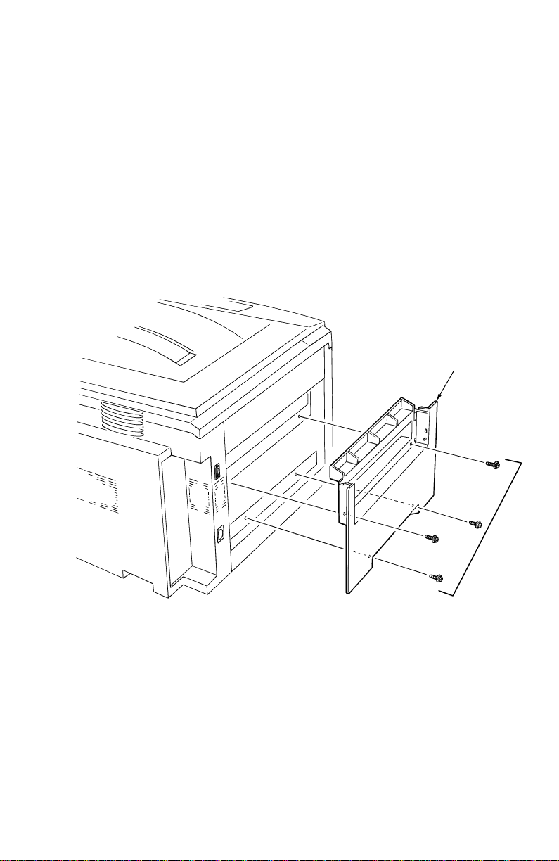
Left-side cover
Warning
1.
Open the top cover.
2.
Remove the drum/toner cartridges. Place them in a lightproof black
bag to protect the drum units from light and store in a safe place.
3.
Remove the front cover as described in “Front cover” on page 90.
4.
Remove the rear cover as described in “Rear cover” on page 89.
5.
Lift the face-up tray to access and remove the two screws underneath.
6.
Remove the four screws securing the left side cover.
7.
Pull the top of the cover out then up to remove.
Switch off the power and disconnect the power cord.
Left-side Cover
B
0725-13
Removing the left-side cover
To reinstall the left-side cover, reverse the removal order.
B
G
Remove Screws
Service Guide
G
91
 Loading...