

Xerox DocuPrint 100 EPS, DocuPrint 135, DocuPrint 115 EPS, DocuPrint 135 EPS, DocuPrint 155 EPS Installation Planning Manual
...Page 1

Xerox DocuPrint 100/115/135/155/180 EPS
installation
planning
701P24750
April, 2005
guide
Page 2

Prepared by:
Xerox Corporation
Global Knowledge and Language Services
800 Philips Road Bldg. 845-17S
Webster, New York 14580
USA
©2005 by Xerox Corporation. All rights reserved.
Copyright protection claimed includes all forms and matters of copyrightable material and information
now allowed by statutory judicial law or hereinafter granted, i ncluding without limitation, material generated
from the software programs di splayed on the screen such as ic ons, screen displays, or look s.
Printed in the United States of America.
XEROX® and all Xerox product names mentioned in this publicat i on are trademarks of XEROX CORPORATION.
Other company trademark s are al so acknowledged.
Changes are periodically made to thi s document. Changes, tec hni cal inaccuracies, and
typographic errors will be corrected
in subsequent editions.
Page 3

Safety
Laser safety . . . . . . . . . . . . . . . . . . . . . . . . . . . . . . . . . . . . . . . . . . . . . . . . . . . . . . . . . . . . . . . . . . v
Ozone information: U. S. only . . . . . . . . . . . . . . . . . . . . . . . . . . . . . . . . . . . . . . . . . . . . . . . . . . . . . v
Operation safety: U. S. . . . . . . . . . . . . . . . . . . . . . . . . . . . . . . . . . . . . . . . . . . . . . . . . . . . . . . . . . .vi
Operation safety: Europe . . . . . . . . . . . . . . . . . . . . . . . . . . . . . . . . . . . . . . . . . . . . . . . . . . . . . . . vii
Warning markings . . . . . . . . . . . . . . . . . . . . . . . . . . . . . . . . . . . . . . . . . . . . . . . . . . . . . . vii
Electrical supply . . . . . . . . . . . . . . . . . . . . . . . . . . . . . . . . . . . . . . . . . . . . . . . . . . . . . . . vii
Ventilation . . . . . . . . . . . . . . . . . . . . . . . . . . . . . . . . . . . . . . . . . . . . . . . . . . . . . . . . . . . . viii
Operator accessible areas . . . . . . . . . . . . . . . . . . . . . . . . . . . . . . . . . . . . . . . . . . . . . . .viii
Maintenance . . . . . . . . . . . . . . . . . . . . . . . . . . . . . . . . . . . . . . . . . . . . . . . . . . . . . . . . . .viii
Before cleaning your product . . . . . . . . . . . . . . . . . . . . . . . . . . . . . . . . . . . . . . . . . . . . .viii
CE mark: Europe only . . . . . . . . . . . . . . . . . . . . . . . . . . . . . . . . . . . . . . . . . . . . . . . . . . . . . . . . . . viii
Radio and telecommunications equipment directive . . . . . . . . . . . . . . . . . . . . . . . . . . . . . . . . . . . .ix
Europe only . . . . . . . . . . . . . . . . . . . . . . . . . . . . . . . . . . . . . . . . . . . . . . . . . . . . . . . . . . . .ix
For further information . . . . . . . . . . . . . . . . . . . . . . . . . . . . . . . . . . . . . . . . . . . . . . . . . . . . . . . . . . x
Introduction
About this guide . . . . . . . . . . . . . . . . . . . . . . . . . . . . . . . . . . . . . . . . . . . . . . . . . . . . . . . . . . . . . . .xi
Contents . . . . . . . . . . . . . . . . . . . . . . . . . . . . . . . . . . . . . . . . . . . . . . . . . . . . . . . . . . . . . .xi
Conventions . . . . . . . . . . . . . . . . . . . . . . . . . . . . . . . . . . . . . . . . . . . . . . . . . . . . . . . . . . xii
Notice . . . . . . . . . . . . . . . . . . . . . . . . . . . . . . . . . . . . . . . . . . . . . . . . . . . . . . . . . . . . . . . . . . . . . . xiii
Table of contents
1 Product overview
System overview . . . . . . . . . . . . . . . . . . . . . . . . . . . . . . . . . . . . . . . . . . . . . . . . . . . . . . . . . . . . 1-1
System components . . . . . . . . . . . . . . . . . . . . . . . . . . . . . . . . . . . . . . . . . . . . . . . . . . . . . . . . . . 1-2
Client workstations and system software . . . . . . . . . . . . . . . . . . . . . . . . . . . . . . . . . . . . . . . . . . 1-4
Supported hardware and operating systems . . . . . . . . . . . . . . . . . . . . . . . . . . . . . . . . 1-5
Client networking software . . . . . . . . . . . . . . . . . . . . . . . . . . . . . . . . . . . . . . . . . . . . . . 1-5
MICR printing features . . . . . . . . . . . . . . . . . . . . . . . . . . . . . . . . . . . . . . . . . . . . . . . . . 1-5
MICR fonts . . . . . . . . . . . . . . . . . . . . . . . . . . . . . . . . . . . . . . . . . . . . . . . . . . . . 1-6
Unsupported features . . . . . . . . . . . . . . . . . . . . . . . . . . . . . . . . . . . . . . . . . . . . 1-7
Host connectivity options . . . . . . . . . . . . . . . . . . . . . . . . . . . . . . . . . . . . . . . . . . . . . . . . . . . . . . 1-7
Remote Services . . . . . . . . . . . . . . . . . . . . . . . . . . . . . . . . . . . . . . . . . . . . . . . . . . . . . . . . . . . . 1-8
2 Controller components and options
Controller overview . . . . . . . . . . . . . . . . . . . . . . . . . . . . . . . . . . . . . . . . . . . . . . . . . . . . . . . . . . . 2-1
Controller components . . . . . . . . . . . . . . . . . . . . . . . . . . . . . . . . . . . . . . . . . . . . . . . . . . . . . . . . 2-1
Sun workstation . . . . . . . . . . . . . . . . . . . . . . . . . . . . . . . . . . . . . . . . . . . . . . . . . . . . . . . 2-2
Controller interface options . . . . . . . . . . . . . . . . . . . . . . . . . . . . . . . . . . . . . . . . . . . . . . . . . . . . 2-9
Online interface . . . . . . . . . . . . . . . . . . . . . . . . . . . . . . . . . . . . . . . . . . . . . . . . . . . . . . . 2-9
Tape drive option . . . . . . . . . . . . . . . . . . . . . . . . . . . . . . . . . . . . . . . . . . . . . . . . . . . . 2-10
3 Printer components and options
Printer components . . . . . . . . . . . . . . . . . . . . . . . . . . . . . . . . . . . . . . . . . . . . . . . . . . . . . . . . . . 3-1
Installation Planning Guide
i
Page 4

Table of contents
Printer configurations . . . . . . . . . . . . . . . . . . . . . . . . . . . . . . . . . . . . . . . . . . . . . . . . . . . . . . . . . 3-2
Bypass transport option . . . . . . . . . . . . . . . . . . . . . . . . . . . . . . . . . . . . . . . . . . . . . . . . . . . . . . . 3-3
Roll feeder support (DP155 and DP180 EPS only) . . . . . . . . . . . . . . . . . . . . . . . . . . . . . . . . . . 3-4
4 Preparing for installation
Responsibilities . . . . . . . . . . . . . . . . . . . . . . . . . . . . . . . . . . . . . . . . . . . . . . . . . . . . . . . . . . . . . 4-1
Xerox responsibilities . . . . . . . . . . . . . . . . . . . . . . . . . . . . . . . . . . . . . . . . . . . . . . . . . . 4-2
Customer responsibilities . . . . . . . . . . . . . . . . . . . . . . . . . . . . . . . . . . . . . . . . . . . . . . . 4-2
Installation planning checklist . . . . . . . . . . . . . . . . . . . . . . . . . . . . . . . . . . . . . . . . . . . . . . . . . . . 4-3
Connectivity requirements . . . . . . . . . . . . . . . . . . . . . . . . . . . . . . . . . . . . . . . . . . . . . . . . . . . . . 4-5
Ethernet specifications . . . . . . . . . . . . . . . . . . . . . . . . . . . . . . . . . . . . . . . . . . . . . . . . . 4-5
Token Ring specifications . . . . . . . . . . . . . . . . . . . . . . . . . . . . . . . . . . . . . . . . . . . . . . . 4-5
Channel-attached specifications . . . . . . . . . . . . . . . . . . . . . . . . . . . . . . . . . . . . . . . . . . 4-6
5 Controller requirements and specifications
Power requirements . . . . . . . . . . . . . . . . . . . . . . . . . . . . . . . . . . . . . . . . . . . . . . . . . . . . . . . . . . 5-1
Outlet configurations . . . . . . . . . . . . . . . . . . . . . . . . . . . . . . . . . . . . . . . . . . . . . . . . . . . 5-1
Environmental specifications . . . . . . . . . . . . . . . . . . . . . . . . . . . . . . . . . . . . . . . . . . . . . . . . . . . 5-3
Space requirements . . . . . . . . . . . . . . . . . . . . . . . . . . . . . . . . . . . . . . . . . . . . . . . . . . . . . . . . . . 5-3
Controller placement . . . . . . . . . . . . . . . . . . . . . . . . . . . . . . . . . . . . . . . . . . . . . . . . . . . 5-3
Guidelines for controller placement . . . . . . . . . . . . . . . . . . . . . . . . . . . . . . . . . . . . . . . . 5-4
Controller hardware specifications and requirements summary . . . . . . . . . . . . . . . . . . . . . . . . 5-4
6 Printer requirements and specifications
Power requirements . . . . . . . . . . . . . . . . . . . . . . . . . . . . . . . . . . . . . . . . . . . . . . . . . . . . . . . . . . 6-1
Outlet configurations . . . . . . . . . . . . . . . . . . . . . . . . . . . . . . . . . . . . . . . . . . . . . . . . . . . . . . . . . 6-2
60 Hz printer outlet voltages . . . . . . . . . . . . . . . . . . . . . . . . . . . . . . . . . . . . . . . . . . . . . 6-2
50 Hz printer outlet voltages . . . . . . . . . . . . . . . . . . . . . . . . . . . . . . . . . . . . . . . . . . . . . 6-3
Environmental specifications . . . . . . . . . . . . . . . . . . . . . . . . . . . . . . . . . . . . . . . . . . . . . . . . . . . 6-5
Space requirements . . . . . . . . . . . . . . . . . . . . . . . . . . . . . . . . . . . . . . . . . . . . . . . . . . . . . . . . . . 6-5
Printer configurations available . . . . . . . . . . . . . . . . . . . . . . . . . . . . . . . . . . . . . . . . . . . 6-6
Printer configuration diagrams . . . . . . . . . . . . . . . . . . . . . . . . . . . . . . . . . . . . . . . . . . . 6-6
Bypass transport specifications . . . . . . . . . . . . . . . . . . . . . . . . . . . . . . . . . . . . . . . . . . . . . . . . . 6-9
Bypass transport dimensions . . . . . . . . . . . . . . . . . . . . . . . . . . . . . . . . . . . . . . . . . . . 6-10
Configuration diagrams with bypass transport . . . . . . . . . . . . . . . . . . . . . . . . . . . . . . 6-12
Space planning guidelines . . . . . . . . . . . . . . . . . . . . . . . . . . . . . . . . . . . . . . . . . . . . . . . . . . . . 6-14
Clearance space requirements . . . . . . . . . . . . . . . . . . . . . . . . . . . . . . . . . . . . . . . . . . 6-15
Shared space between components . . . . . . . . . . . . . . . . . . . . . . . . . . . . . . . 6-15
Shared space configuration diagrams . . . . . . . . . . . . . . . . . . . . . . . . . . . . . . 6-15
Floor leveling . . . . . . . . . . . . . . . . . . . . . . . . . . . . . . . . . . . . . . . . . . . . . . . . . . . . . . . . 6-18
Delivery access requirements . . . . . . . . . . . . . . . . . . . . . . . . . . . . . . . . . . . . . . . . . . . 6-19
Turning radius . . . . . . . . . . . . . . . . . . . . . . . . . . . . . . . . . . . . . . . . . . . . . . . . 6-19
Printer hardware specifications and requirements summary . . . . . . . . . . . . . . . . . . . . . . . . . . 6-23
Space planning templates . . . . . . . . . . . . . . . . . . . . . . . . . . . . . . . . . . . . . . . . . . . . . . . . . . . . 6-26
7 System connections
Cable lengths . . . . . . . . . . . . . . . . . . . . . . . . . . . . . . . . . . . . . . . . . . . . . . . . . . . . . . . . . . . . . . . 7-1
Cable locations . . . . . . . . . . . . . . . . . . . . . . . . . . . . . . . . . . . . . . . . . . . . . . . . . . . . . . . . . . . . . . 7-1
Channel attachments . . . . . . . . . . . . . . . . . . . . . . . . . . . . . . . . . . . . . . . . . . . . . . . . . . . . . . . . . 7-2
8 Installation
ii Installation Planning Guide
Page 5

Installation process . . . . . . . . . . . . . . . . . . . . . . . . . . . . . . . . . . . . . . . . . . . . . . . . . . . . . . . . . . . 8-1
Your responsibilities . . . . . . . . . . . . . . . . . . . . . . . . . . . . . . . . . . . . . . . . . . . . . . . . . . . . . . . . . . 8-2
Defining the printer to the host . . . . . . . . . . . . . . . . . . . . . . . . . . . . . . . . . . . . . . . . . . . . . . . . . . 8-2
Software licensing . . . . . . . . . . . . . . . . . . . . . . . . . . . . . . . . . . . . . . . . . . . . . . . . . . . . . . . . . . . 8-3
Ongoing maintenance . . . . . . . . . . . . . . . . . . . . . . . . . . . . . . . . . . . . . . . . . . . . . . . . . . . . . . . . 8-3
Routine maintenance . . . . . . . . . . . . . . . . . . . . . . . . . . . . . . . . . . . . . . . . . . . . . . . . . . 8-3
Meter reading and reporting . . . . . . . . . . . . . . . . . . . . . . . . . . . . . . . . . . . . . . . . . . . . . 8-4
A Supplies
Paper and other throughput stocks . . . . . . . . . . . . . . . . . . . . . . . . . . . . . . . . . . . . . . . . . . . . . . A-1
Selecting paper . . . . . . . . . . . . . . . . . . . . . . . . . . . . . . . . . . . . . . . . . . . . . . . . . . . . . . . A-1
Paper sizing and print speed . . . . . . . . . . . . . . . . . . . . . . . . . . . . . . . . . . . . . . . . . . . . . A-3
Paper care . . . . . . . . . . . . . . . . . . . . . . . . . . . . . . . . . . . . . . . . . . . . . . . . . . . . . . . . . . . A-9
Other supplies . . . . . . . . . . . . . . . . . . . . . . . . . . . . . . . . . . . . . . . . . . . . . . . . . . . . . . . . . . . . . A-11
Dry ink . . . . . . . . . . . . . . . . . . . . . . . . . . . . . . . . . . . . . . . . . . . . . . . . . . . . . . . . . . . . . A-12
Fuser agent . . . . . . . . . . . . . . . . . . . . . . . . . . . . . . . . . . . . . . . . . . . . . . . . . . . . . . . . . A-12
Developer . . . . . . . . . . . . . . . . . . . . . . . . . . . . . . . . . . . . . . . . . . . . . . . . . . . . . . . . . . A-12
Diskettes . . . . . . . . . . . . . . . . . . . . . . . . . . . . . . . . . . . . . . . . . . . . . . . . . . . . . . . . . . . A-13
Cartridge tapes . . . . . . . . . . . . . . . . . . . . . . . . . . . . . . . . . . . . . . . . . . . . . . . . . . . . . . A-13
Stacker containers and pallets (optional) . . . . . . . . . . . . . . . . . . . . . . . . . . . . . . . . . . A-13
Fonts . . . . . . . . . . . . . . . . . . . . . . . . . . . . . . . . . . . . . . . . . . . . . . . . . . . . . . . . . . . . . . A-13
Consumable supplies tables . . . . . . . . . . . . . . . . . . . . . . . . . . . . . . . . . . . . . . . . . . . . . . . . . . A-14
Paper and special stocks tables . . . . . . . . . . . . . . . . . . . . . . . . . . . . . . . . . . . . . . . . . A-14
Complete supplies list for the printer . . . . . . . . . . . . . . . . . . . . . . . . . . . . . . . . . . . . . . A-19
Ordering supplies . . . . . . . . . . . . . . . . . . . . . . . . . . . . . . . . . . . . . . . . . . . . . . . . . . . . . . . . . . . A-20
Table of contents
Paper width and throughput speed (LCDS printing only) . . . . . . . . . . . . . . . . . A-3
Paper size and pitch mode minimum and maximum . . . . . . . . . . . . . . . . . . . . A-5
Feed direction for standard paper sizes . . . . . . . . . . . . . . . . . . . . . . . . . . . . . . A-7
B Xerox support services
Xerox Customer Service Support Center . . . . . . . . . . . . . . . . . . . . . . . . . . . . . . . . . . . . . . . . . . B-1
Xerox Printing Systems Customer Support Center (U. S.) . . . . . . . . . . . . . . . . . . . . . . . . . . . . . B-2
Xerox Documentation and Software Services (U. S.) . . . . . . . . . . . . . . . . . . . . . . . . . . . . . . . . B-3
Operator training . . . . . . . . . . . . . . . . . . . . . . . . . . . . . . . . . . . . . . . . . . . . . . . . . . . . . . . . . . . . B-3
Xerox Customer Education . . . . . . . . . . . . . . . . . . . . . . . . . . . . . . . . . . . . . . . . . . . . . . . . . . . . B -3
Xerox Font Services . . . . . . . . . . . . . . . . . . . . . . . . . . . . . . . . . . . . . . . . . . . . . . . . . . . . . . . . . . B-4
C Related publications
DocuPrint 100/115/135/155/180 EPS documentation . . . . . . . . . . . . . . . . . . . . . . . . . . . . . . . . C-1
NPS/IPS publications . . . . . . . . . . . . . . . . . . . . . . . . . . . . . . . . . . . . . . . . . . . . . . . . . . . . . . . . . C-1
Index
Installation Planning Guide iii
Page 6

Table of contents
iv Inst allation Planning Guide
Page 7

Laser safety
Safety
WARNING: Adjustments, use of controls, or performance of
procedures other than those specified herein may result in
hazardous light exposure.
The Xerox DocuPrint printers are certifi ed to comply with the
performance standards of the U.S. Department of Health,
Education, and Welfare for Class 1 laser products. Class 1 laser
products do not emit hazardous radiation. The DocuPrint printers
do not emit hazardous radiation because the laser beam is
completely enclosed during all modes of customer operation.
The laser danger labels on the system are for Xerox service
representatives and are on or near panels or sh ields that must be
removed with a tool.
DO NOT REMOVE LABELED PANELS OR PANELS NEAR
LABELS. ONLY XEROX SERVICE REPRESENTATIVES HAVE
ACCESS TO THESE PANELS.
Ozone information: U. S. only
Installation Planning Guide v
This product produces ozone during normal operati on. The
amount of ozone produced depends on copy volume. Ozone is
heavier than air. The environmental p a rameters specified in the
Xerox installation i nstructi ons ensure th at concent ration l evels are
within safe limits. If you need additional information concerning
ozone, call 1-800-828-6571 to request the Xerox publication
Facts About OZONE.
Page 8

Safety
Operation safety: U. S.
Your Xerox equipment and supplies have been designed and
tested to meet strict safety requirements. They have been
approved by safety agencies, and they comply with environment al
standards. Please observe the following precautions to ensure
your continued safety.
WARNING: Improper connection of the equipment grounding
conductor may result in risk of electrical shock.
• Always connect equipment to a properly grounded elect ri cal
• Never use a ground adapter plug to connect equipment to an
• Always place equipment on a solid support surface with
• Always use materials and supplies specifically designed for
outlet. If in doubt, have the outlet checked by a qualified
electrician.
electrical outlet that lacks a ground connection terminal.
adequate strength for its weigh t.
your Xerox equipment. Use of unsuit able materials may result
in poor performance and may create a hazardous situation.
• Never move either the printer or the controller without first
contacting Xerox for approval.
• Never attempt any maintenance that is not specifically
described in this documentation.
• Never remove any covers or guards that are fastened with
screws. There are no operator-serviceable areas within these
covers.
• Never override electrical or mechanical interlocks.
• Never use supplies or cleaning materials for other than their
intended purposes. Keep all materials out of the reach of
children.
• Never operate the equipment if you notice unusual noises or
odors. Disconnect the power cord f rom the electrical outlet and
call service to correct the problem.
If you need any additional safety information concerning the
equipment or materials Xerox supplies, call Xerox Product Safety
at the following toll-free number in the United St ates:
1-800-828-6571
For customers outside the United States, contact your local Xerox
representative or operating company.
vi Installation Planning Guide
Page 9
Operation safety: Europe
This Xerox product and supplies are manufactured, tested and
certified to strict safety regulations, electromagnetic regulations
and established environmental standards.
Any unauthorised alteration, whic h may include the addition of
new functions or connection of external devices, may impact the
product certification.
Please contact your Xerox representative for more information.
Wa rning markings
All warning instructions marked on or suppli ed with the product
should be followed.
This WARNING alerts users to areas of the produc t where there is
the possibility of personal damage.
Safety
Electrical supply
This WARNING alerts users to areas of the product where there
are heated surfaces, which should not be touched.
This product shall be operated from the type of elec trical supply
indicated on the product’s data plate label . If you are not sure that
your electrical supply meets the req uirements, please consul t your
local power company for advice.
WARNING
This product must be connected to a protective eart h cir cuit. This
product is supplied with a plug that has a protectiv e earth pi n. This
plug will fit only into an earthed electrical outlet. This is a safety
feature. Always connect equipment to a properly grounded
electrical outlet. If in doubt, have the outlet checked by a qualified
electrician.
Installation Planning Guide vii
To disconnect all electrical power to the product, the disconnect
device is the power cord. Remove the plug from the electrical
outlet.
Page 10

Safety
Ventilation
Slots and opening in the enclosure of the product are provided for
ventilation. Do not block or cover the ventilation vents, as this
could result in the product overheati ng.
This product should not be placed in a built-in installation unless
proper ventilation is provided, please contact your Xerox
representative for advice.
Never push objects of any kind into the ventilation vents of the
product.
Operator accessible areas
This product has been designed to rest rict operator access to safe
areas only. Operator access to hazardous areas is restricted with
covers or guards, which would require a tool to remove. Never
remove these covers or guards.
Maintenance
Before cleaning your product
CE mark: Europe only
Any operator product maintenanc e procedures will be descr ibed in
the user documentation supplied with the product. Do not carry
out any maintenance on the product, which is not descr ibed in t he
customer documentation.
Before cleaning this pro duct, unplug the product from the el ectrical
outlet. Always use materials specifi cally designated for this
product, the use of other materi als may result in po or performance
and may create a hazardous situation. Do not use aerosol
cleaners, they may be flammable under certain circumstances.
January 1, 1995: Council Directive 73/23/EEC, amended by
Council Directive 93/68/EEC, approximation of the laws of the
member states related to low voltage equipment.
January 1, 1996: Council Directive 89/336/EEC, appr oximation of
the laws of the member states related to electromagnetic
compatibility.
viii Installation Planning Guide
Page 11

March 9, 1999: Council Directi ve 99/5/EC, on radio equipment and
telecommunications terminal equipment and the mutual
recognition of their conformity.
A full declaration of conformity, defining the relevant directives and
referenced standards, can be obtained from your Xerox
representative.
In order to allow this equipment to operate in proximity to
Industrial, Scientific and Medical (ISM) equipment, the external
radiation for the ISM equipment may have to be limited or special
mitigation measures taken.
This is a Class A product. In a domestic environment thi s product
may cause radio frequency interference, in which case the user
may be required to take adequate measures.
Shielded interface cables must be used with this product to
maintain compliance with Council Dir ective 89/36/EEC.
Radio and telecommunications equipment directive
Safety
Europe only
Certification to 1999/5/EC Radio Equipment and
Telecommunications Terminal Equipment Directive:
This Xerox product has been self-certified by Xerox for panEuropean single terminal connection to the analog publi c switched
telephone network (PSTN) in accordance with Directive 1
999/5/EC.
The product has been designed to work with the national PSTNs
and compatible PBXs of the following countries:
• Austria • Germany • Luxembourg • Sweden
• Belgium • Greece • Netherlands • Switzerland
• Denmark • Iceland • Norway • United Kingdom
• Finland • Ireland • Portugal
• France • Italy • Spain
In the event of problems, contact your local Xerox representative
in the first instance.
Installation Planning Guide ix
This product has been tested to, and is compliant wit h, TBR21, a
specification for terminal equipment for use on analog switched
telephone networks in the European Economic area.
Page 12

Safety
The product may be configured to be compatible with other
country networks. Please contact your Xerox representative if
your product needs to be reconnected to a network in another
country. This product has no user-adjustable settings.
NOTE: Although this product can use either loop disconnect
(pulse) or DTMF (tone) signaling, it should be set to use DTMF
signaling. DTMF signaling provides reliabl e and faster call setup.
Modification or connection to external control software, or to
external control apparatus not authorized by Xerox, inval idat es its
certification.
For further information
For more information on Environment, Health and Safety in
relation to this Xerox product and supplies, please contact the
following customer help lines:
Europe:+44 1707 353434
USA:1 800 8286571
Canada:1 800 8286571
x Installation Planning Gu ide
Page 13

About this guide
Introduction
This document helps you prepare for delivery and installation of
your new Xerox DocuPrint printing system.
This guide is intended for the person responsible for coordinating
the installation of the Xerox DocuPrint 100/115/135/155/180
Enterprise Printing System at your site. It lists the tasks you must
complete before installation can begin, as well as your
responsibilities during the installation. This guide i s a companion
to the Getting Ready for Installation manual.
NOTE: All information in this guide, unless otherwise stated,
pertains to the Xerox DocuPrint 100/ 115/135/155/180 EPS
printers.
Contents
The Inst allat ion Planning Gui de is one of several manuals that are
available for your new printing system. You receive it in advance
of hardware delivery to help you prepare your site for the delivery
and installation of the system. A set of user material will be
delivered with the system.
Before using this guide, become familiar with its contents and
conventions.
This guide contains the following:
• Chapter 1, “Product overview,” provides an overview of the
Xerox DocuPrint 100/115/135/155/180 Enterprise Printing
System.
• Chapter 2, “Controller components and options,” describes
controller hardware, software, and options.
• Chapter 3, “Printer components and options,” describes
printer components, configurations, and options.
• Chapter 4, “Preparing for installation,” provides a checklist of
tasks that must be accomplished before the in stallat ion. It also
explains connectivity requirements for submitting documents
from the host or client to the printing system.
Installation Planning Guide xi
• Chapter 5, “Controller requirements and specifications,”
Page 14

Introduction
describes power, environmental, and space requirements for
the controller.
• Chapter 6, “Printer requirements and specifications,”
describes power, environmental, and space requirements for
the printer. Space planning guidelines and diagrams are
provided to help you set up the work area.
• Chapter 7, “System connections,” provides cable requirement s
for the printing system.
• Chapter 8, “Installation,” describes the activities that occur
during installation. It also describes ongoing maintenance
activities.
• Appendix A, “Supplies,” describes how to sel e ct, store, and
use supplies for the printing system. It also provides a list of
consumable supplies you can order.
• Appendix B, “Xerox support services,” explains how to utilize
available Xerox support services.
• Appendix C, “Related publications, ” lists other Xerox
documents that are part of this publication set.
Conventions
• An index is provided at the end of this document.
This guide uses the following conventions :
• Initial capita l and an gle brackets: Within procedures, the
names of keys are shown with an initial capital and within
angle brackets (for example, pr ess <Enter>).
• Angle brackets: Variable information, or the position of a
specified argument in the command syntax, appears in angle
brackets (for example, List Fonts <pattern>).
• Fixed pitch font: Within procedures, text and numbers that
you enter are shown in a bold, fixed pit ch (“computer”) font (for
example, enter privilege operator).
Messages that appear on the controller screen are shown in
the medium weight fixed pitch font (for example, Online
Gateway disabled).
• The word “enter” within procedures: The two-step process
of keying in data and pressing <Enter> (for example, enter y).
xii Installation Planning Gu ide
• Italics: Document and li brary names are shown in italics (for
example, the Xerox DocuPrint NPS/IPS Guide to Managing
Print Jobs).
Variable elements in a command or directory path are also
shown in italics (for example, var/spool/XRXnps/ filename).
Vertical bars: Alternatives to specified arguments are
separated by vertical bars (f or example, Set Time <Time |
Page 15

Notice
Introduction
Remote Host Name | IP Address>).
NOTE: Notes are hints that help you perform a task or under stand
the text.
CAUTION: Cautions alert you to an action that could damage
hardware or software.
WARNING: Warnings alert you to conditions that may affect the
safety of people.
This publication may contain descriptions of concepts and
features not currently available for your Xerox printing system.
Consult your Xerox sales represent ativ e or your operat in g system
software program descripti on for additional information.
Installation Planning Guide xiii
Page 16

Introduction
xiv Installation Planning Guide
Page 17
System overview
1 Product overview
This chapter provides an overview of the features and functions of
the Xerox DocuPrint 100/115/135/155/180 Enterprise Printing
System (EPS).
The Xerox DocuPrint 100/115/135/155/180 EPS prints high
quality, high resolution monochrome documents in simplex (onesided) or duplex (two-sided) at high production speeds from
LCDS, PostScript, PCL, IPDS, and other data streams.
The printer supports:
• Duplex printing
• Offline printing of data from 9-track and 18/36-track tape
drives
• Media handling of multiple weights, sizes, and types
• Optional modules for enhanced finishing and output to third
party devices
• Optional high capacity feeder stacker modules, which provide
additional feeder trays and output bins
• High resolution printing of supported data streams (shown in
the following table)
Table 1-1 Data stream resolution
Data stream Input resolution Print resolution:
DP155 and DP180
LCDS 300 by 300 dpi 600 x 2400 dpi 600 by 600 dpi
PostScript and PCL 300 by 300 dpi or
600 by 600 dpi
IPDS* 240 by 240 dpi* or
300 by 300 dpi or
600 by 600 dpi**
600 x 2400 dpi 600 by 600 dpi
600 x 2400 dpi 600 by 600 dpi
Print resolution:
DP100, DP115, and DP135
Installation Planning Guide 1-1
*Requires additional equipment to enable.
**600 by 600 dpi input resolution support ed for f u ll page IOCA
only
Page 18
Product overview
System components
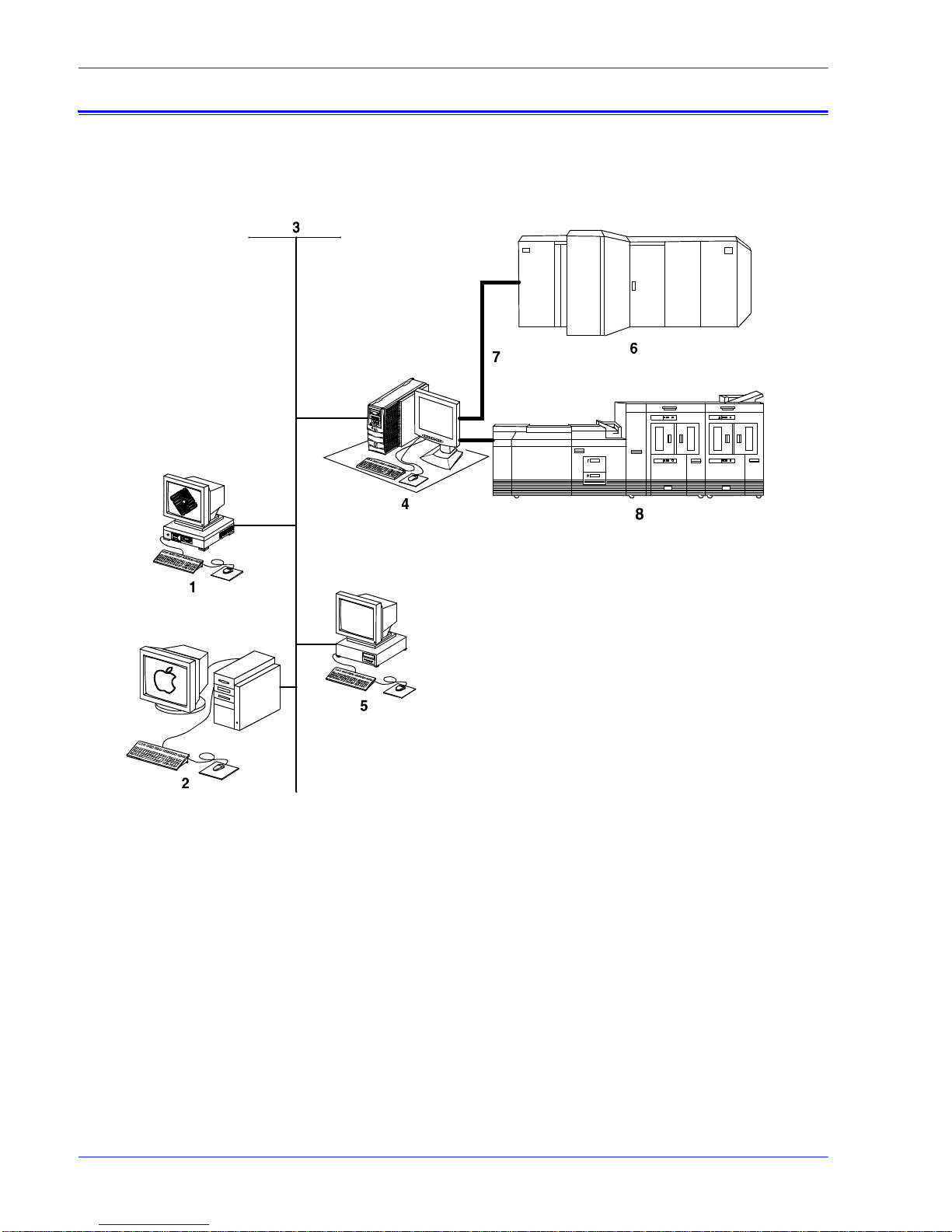
The following figure shows the configurations supported for the
Xerox DocuPrint 100/115/135/155/180 EPS.
1-2 Installat ion Planning Guide
QTC0702A-SOR
Figure 1-1 Configurations supported by Xerox DocuPrint
100/115/135/155/180 EPS
1. Sun UNIX client workstation
2. Apple Macintosh client workstation
3. Network connection
4. Controller
5. PC client workstation
6. Mainframe host computer
7. Bus and tag cables (channel connection)
8. Print engine
The following sections briefly describe the functionality of each
system component.
Page 19

Product overview
DocuPrint 100/115/
135/155/180 EPS
Customer-supplied
client workstation
The DocuPrint 100/115/135/155/180 EPS includes the controller,
printer and all appropriat e sof tware. “DocuPri nt printe r” or “pr inter”
refers to the base printer engine (IOT) only.
NOTE: Some printer configurations may include a control console
(not shown).
A host mainframe computer or network-connected PC, Apple
Macintosh, or Sun UNIX client workstati on submits print jobs to
the printing system. The print job may be in any of the following
data formats:
• PostScript levels 2 and 3
• HP PCL5c, PCL5e, and PCL6: Hewlett-Packard Print Control
Language
• LCDS: Line Conditioned Data Stream
• IPDS: Intelligent Printer Data Stream
• ASCII: American Standard Code for Information Interchange
• PDF: Portable Document Format
• TIFF: Tagged Image File Format
• VIPP: Variable Data Int elligent PostScript Print Ware
Customer-supplied
network and
channel connection
Xerox-supplied
controller
NOTE: Enablement of IPDS data format may require additional
equipment. Contact your local Xerox representative for more
information.
The customer needs to supply one or more of the following
communication connections:
• Ethernet local area network (LAN) running TCP/IP, AppleTalk,
or Novell NetWare network protocol software.
• Online (channel-attached): Bus and tag cables supporting the
IBM 3211/4245 interface.
• Token ring LAN running TCP/IP, Novell 3.x, or AppleTalk
network protocol software.
NOTE: Enablement of channel-attached and Token Ring
communication connection requires additiona l equipment. Contact
your local Xerox represent ative for more information.
The controller (monitor, processor, DVD drive, keyboard, mouse,
diskette drive, and cartridge tape drive) accepts the print job from
the host mainframe computer or network-connected client
workstation, converts the files into page images, and sends the
page images to the print engine. External 9-track and 18/36-track
tape drives can be used for resource loading and for offline
printing.
Xerox-supplied
printer
Installation Planning Guide 1- 3
The printer (also known as t he image output termina l [IOT] or pr int
engine) accepts page image dat a from the controller and prints
the document according to the print options specified by the user.
The printer also handles paper stacking, collating, and optional
finishing.
Page 20
Product overview
NOTE: It is the responsibility of the customer to supply , ins tall, and
maintain hardware and software on any PC, Sun workstation, or
Macintosh workstation that is used to generate documents for
printing on the DocuPrint 100/115/135/155/180 EPS. You are also
responsible for obtaining, installing, and maintaining the required
Ethernet local area network , transceivers, b us and tag cables, and
any other connecting cables.
The Xerox DocuPrint 100/115/135/155/180 EPS prints LCDS data
from a mainframe host computer, emulating an IBM 4245 or 3211
line printer. The printing system can receive data over a channel
through bus and tag cables and throug h the Socket Gateway or lpr
using TCP/IP protocol.
Table 1-2 Throughput speed
Printing
system
Maximum
throughput
speed
Maximum throughput
speed with 7 by 10 inch/
178 by 254 mm paper
DP100 EPS 100 ppm 100 ppm
DP115 EPS 115 ppm 115 ppm
DP135 EPS 135 ppm 154 ppm
DP155 EPS 155 ppm 155 ppm
DP180 EPS 180 ppm 206 ppm
NOTE: Maximum throughput speed with 7 by 10 inch / 178 by 254
mm paper requires the 7 by 10 inch enablement kit.
Xerox is responsible for the phys ical inst alla tion and ser vice of the
printer and controller hardware and software components. You
have the general responsibility for the site of ensuring that the
correct personnel, supplies, and network hardware and software
are available. Refer to the “Pr ep ari ng for ins t all ation” chapt er for a
detailed description of the shared responsibilities of the customer
and of Xerox.
Client workstations and system software
1-4 Installat ion Planning Guide
To submit print jobs to the printing system, the customer needs to
provide the proper client hardware as well as operating system
and network software.
Page 21

Supported hardware and operating systems
The Xerox DocuPrint 100/115/135/155/180 EPS supports the
following types of networked client wo rkstations and operating
systems:
• Sun Workstation r unning Solaris 2.3 or higher
• PC running MS-DOS 5.0 or higher , using Ethernet with TCP/IP
or Novell NetWare 3.11 or higher, Windows 95/98, Windows
NT 4.0, Windows Millennium, Windows 2000, or Windows XP
• PC running MS-DOS 5.0 or higher, with one or more of the
following TCP/IP packages:
– PC/TCP Network Software by FTP Software, Inc.
– Pathway Access by Wollongong Group, Inc.
– PC-NFS by Sun Select
• Apple Macintosh running 8.6 through 9.x, or 10.1 or higher in
Classic mode, using AppleTalk through Ethernet
• Any system that supports RFC-1179 lpr/lpd
The printing system software may be compatible with workstation
models and software versions other than those l ist ed above.
Product overview
Client networking software
Xerox client software, a third-party TCP/IP lpr networking
software, Novell, or Apple/Macintosh Printer Access Protocol
(PAP) networking softw are must be installed on your client
workstations or downloaded from the controller. This software
provides an interface with the contro ller, which allows you to
submit print jobs and check job status.
NOTE: The printing options that are available to a client user vary
according to the networking software loaded on the client
workstation.
Additional information on submitting j obs from a cli ent workstation
is specified in othe r documents that are p art of this publicati on set.
MICR printing features
The DocuPrint 100/115/135/155/180 MX systems produc e a
Magnetic Ink Character Recognition (MICR) line on negotiable
and turnaround documents such as checks and bills. The MICR
printing system prints documents using magnetic ink and special
fonts to create machine readable information that allows for quick
document processing.
Installation Planning Guide 1- 5
Page 22

Product overview
In general, MICR is used to print accounting and routing
information on blank checks and ot her negotiable document s. The
magnetic encoding capabil iti es can be used f or any pri nted out put.
The following illustrates a check printed with a MICR line in U.S.
format. The entire MICR line, which consist s of numbers and
characters (called symbols), is printed using magnetic ink.
ERA
PAY ROLL ACCOUNT
PAYTOTHE ORDER OF
ERA CORP O R ATION P.O.BOX 9968 KENAN,N.Y.146008
JEAN L.MAGNIN
484 NORTH PROSPECT
CARUBA BEACH, CA 80297
PAYABLE IF DESIRED AT SOUTHERN PACIFIC
NATIONALTRUST AND SAVINGS ASSOC.
OMAHA, NEBRASKA
SECURITYTRUST COMPANY OF KENEAN,N.Y.
Figure 1-2 Example of a check printed with MICR line (U. S.)
The DocuPrint 100/115/135/155/180 MX systems meet ABA
standards and ANSI and ISO specifications for automatic check
handling. They print the variable data and the MICR line at the
same time. This single-p ass printing c apability reduc es processing
time and costs.
06-29-84
VOID AFTER 90 DAY S
NOT NEGOTIABLE
$* * * *980 28
12-35/9290
DOLLARS CENTS
MICR Line
1962721
$980.28
50-16
223
MICR fonts
MICR fonts The MICR fonts include the following .
1-6 Installat ion Planning Guide
Xerox provides a set of 300 and 600 dpi E13B and CMC7 MICR
fonts for use with your DocuPrint 100/115/135/155/180 MX
system. To receive the high print qu ality gua ranteed by Xerox, yo u
must use these MICR fonts.
CMC7 fonts have been adopted in vari ous countr ies out side of the
U.S., and are the official standard in France. Like the E13B font,
they are magnetically readable, but wit h a different character
design and recognition criteria. (Currently, CMC7 is available only
through Xerox Europe.)
E13B fonts:
• E13B
• E13B Landscape
Page 23

Product overview
• E13B Test
• E13B Test Landscape.
CMC7 fonts:
•CMC7
• CMC7 Landscape
•CMC7 Test
• CMC7 Test Landscape
The “Test” fonts are non-readable MICR hollow bitmap (or outline)
fonts, provided for testing MICR applications and printing nonnegotiable documents.
LCDS MICR fonts The MICR fonts that are used for printing an LCDS data stream
include the following.
E13B4 fonts:
• E13B4 Portrait
• E13B4 Landscape
• E13B4 Inverse Portrait
• E13B4J
CMC7 fonts:
• CMC74 Portrait
• CMC74 Landscape
• CMC74 Inverse Portrait
• CMC74J
Unsupported features
The DocuPrint 100/115/135/155/180 EPS does not support the
security and audit feature or bar code reading. In addition,
although the Line Thickening selection and the Virtual Printer
Imaging parameters are available when you use MICR, using
these features when printing MICR documents is not
recommended, as they corrupt the MICR line.
In general, all print quali ty adj ustm ent s and enhance ment sett ing s
should be set at the nominal settings when printing MICR output.
Host connectivity options
Installation Planning Guide 1- 7
The Xerox DocuPrint 100/115/135/155/180 EPS can receive data
in the following w a y s:
• Over a channel through a bus and tag cable connection
• Through a network interface, using Novell, TCP/IP, or
Page 24

Product overview
Remote Services
AppleTalk protocols
Your system may have one or both of these configurations.
Remote Services is a web based application that enables direct
communication between DocuSP and Xerox support. This service
enables:
• Quick resolution of First Call issues
• Automated workflow monitoring
• Real-time trouble-shooting and analysis of print jobs
• Live demonstrations of new product features
For additional information, contact your local Xerox
representative.
1-8 Installat ion Planning Guide
Page 25

2 Controller component s and
Controller overview
options
This chapter describes the components and options available for
the Xerox DocuPrint 100/115/135/155/180 EPS controller.
The controller receives dat a from a mainframe host or a
workstation client, processes the data, and sends it to the printer.
The controller also provides the printer with print data and
commands, and receives status information from the printer.
The controller consists of a high performance Sun workstation
processor running Solaris s oftware. Al so resident on th e controller
is the DocuSP software, which manages all printing, diagnostic,
and administrative functions on the pr inting system.
The DocuSP software includes a full colo r graphical user interface
(GUI). Using the GUI, you set up and configure the system, set up
and implement system options, and manage print jobs.
DocuSP remote access
(Remote Workflow)
Remote Workflow, a remote graphical user interface, is available
for installation from a CD. The remote GUI allows you to manage
your DocuSP-based printers from a single PC or Sun work stati on.
You may set your preferences from the remote client to disable or
enable some or all connections.
Remote Workflow allows you to configure the printers that you
want to manage, and provides real t ime status of the printer s. You
may switch between the printers that you are managing, but you
can display only one printer GUI at a time.
The Remote Workflow GUI looks and functions the same as the
local DocuSP GUI on the controller.
Controller components
The controller consists of a specially-configured Sun workstation
and uses proprietary Xerox hardware, firmware, and software.
Your controller has one of two possible configurations, described
in the following sections.
NOTE: Controller hardware configurations are subject to change,
to keep up with technology advances.
Installation Planning Guide 2-1
Page 26
Sun workstation
Sun Blade 1000/2000
configuration
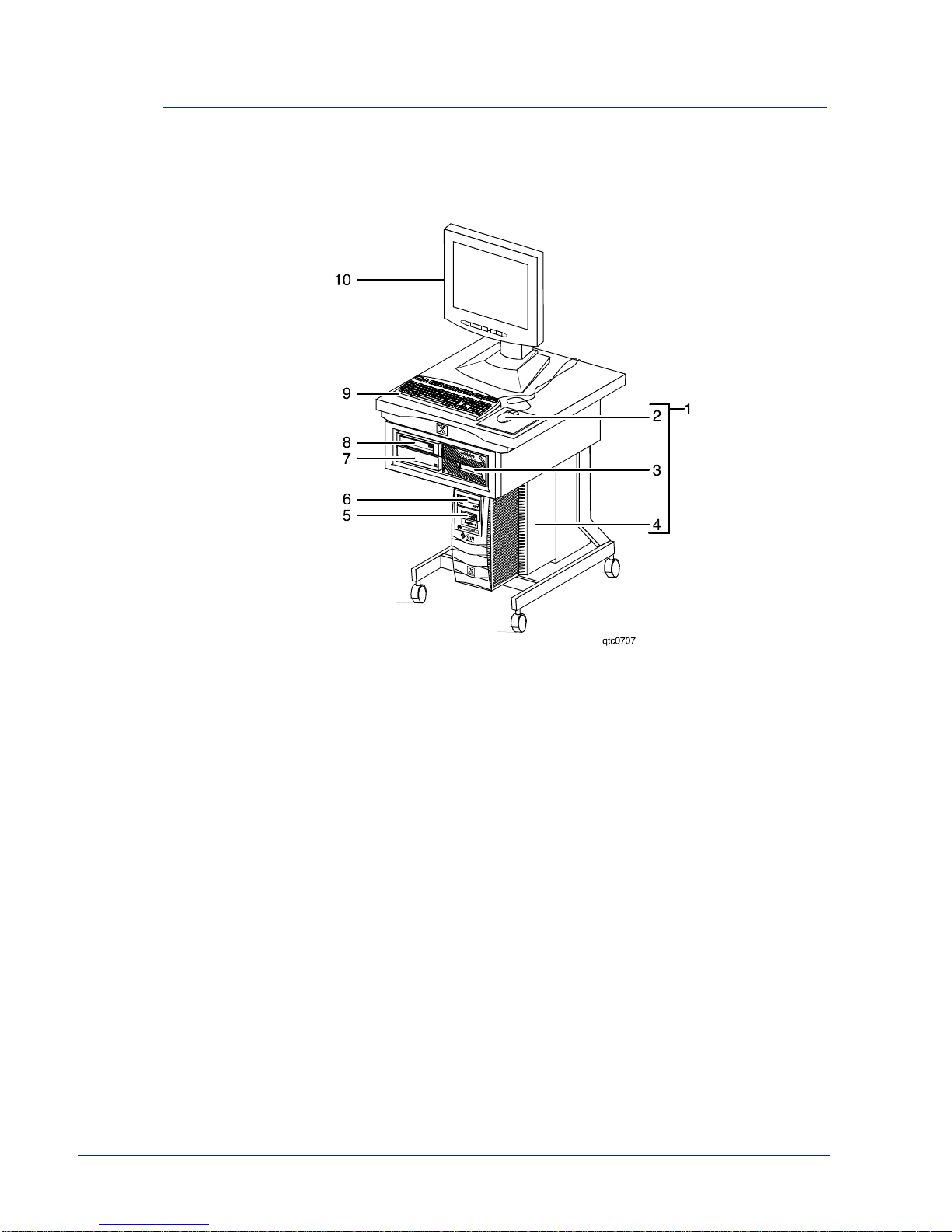
The controller is based on either the Sun Blade 1000/2000, Sun
Blade 2500, or the Sun W1100z workstations with highperformance architecture for complex processing tasks.
Figure 2-1 Sun Blade 1000/2000 controller
1. Controller stand
2. Mouse
3. 18/36-track cartridge tape drive (optional)
4. Processor
5. Diskette drive
6. CD drive
7. Quarter-inch cartridge (QIC) tape drive
8. External fixed disk drive (optional)
9. Keyboard
10. Display monitor
The Sun Blade 1000/2000 contains the following hardware
components:
• Processor (system unit) containing the following:
– One or two UltraSPARC III high-speed central processing
unit (CPU) modules
• DP 100, 115, and 135: 1 CPU
• DP 155 and 180: 2 CPUs
Installation Planning Guide 2-2
Page 27

NOTE: In XE, all printers use a dual CPU configuration.
– 1 or 2 GB of memory (one or two 1-GB Dual In-line
Memory Modules, or DIMMs)
• DP 100, 115, and 135: 1 GB
• DP 155 and 180: 1 or 2 GB
NOTE: In XE, all printers use a 2 GB memory
configuration.
– Hard disk drive
• Sun Blade 1000: 36 GB
• Sun Blade 2000: 73 GB
– CD drive
– Diskette drive: uses 3.5 inch, 1. 44 MB, double-sided, high-
density diskettes
– Ethernet
– Two Printer Controller Interface (PCI ) boards to interface
with the printer
– PGx64 video graphics board
• Universal Serial Bus (USB) keyboard and three-button mous e
• 17-inch flat panel monitor
Installation Planning Guide 2-3
Page 28
Sun Blade 2500 and
Sun W1100z
configuration
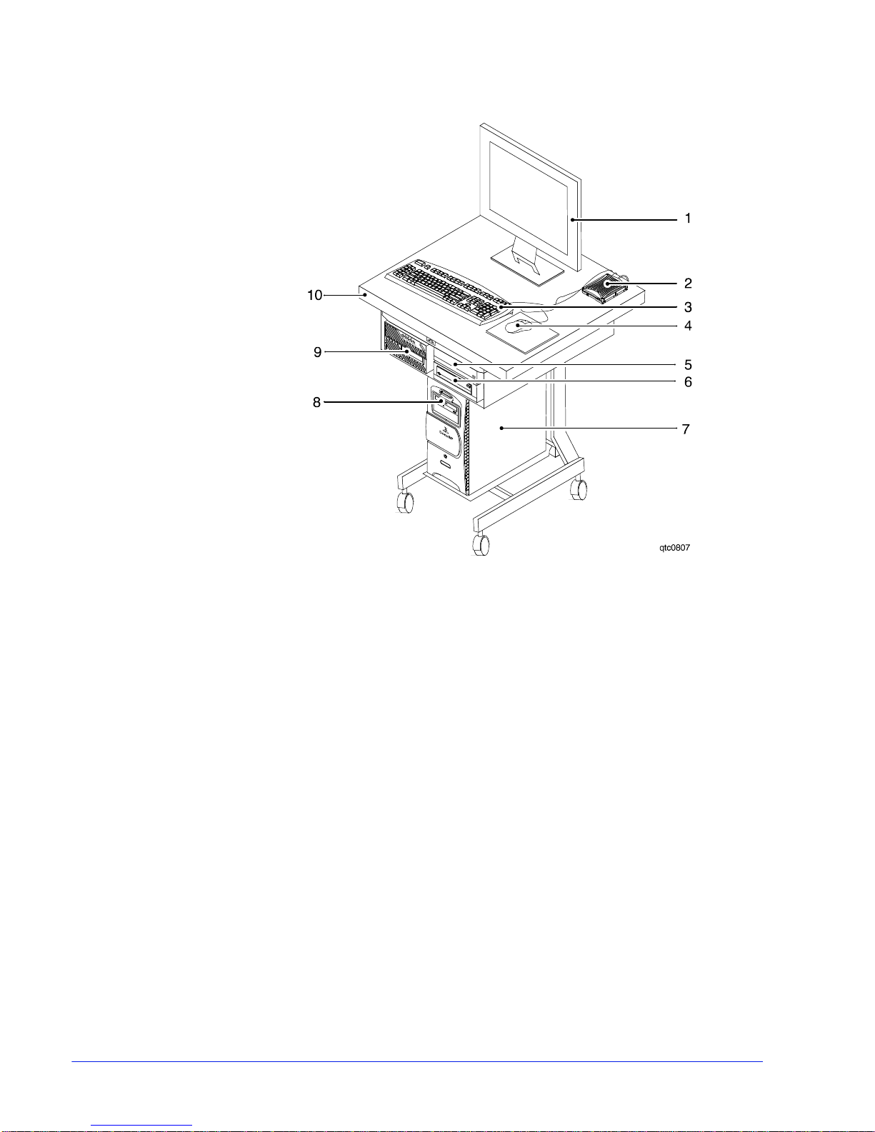
Figure 2-2 Sun Blade 2500 and Sun W1100z controller
1. Display monitor
2. External diskette drive
3. Keyboard
4. Mouse
5. External fixed disk drive (optional)
6. Quarter-inch cartridge (QIC) tape drive
7. Processor
8. DVD/CD-RW drive
9. 18/36-track cartridge tape drive (optional)
10. Controller stand
The Sun workstation contain s the following hardware
components:
• Processor (system unit) containing the following:
– One UltraSPARC IIIi high-speed processing unit (CPU)
module
– 1 or 2 GB of memory (one or two 1-GB Dual In-line
Memory Modules, or DIMMs)
• DP 100, 115, and 135: 1GB
Installation Planning Guide 2-4
• DP 155 and 180: 2 GB
Page 29

NOTE: In Xerox Europe, all printers use a 2 GB memory
configuration.
– 36 GB hard disk drive
– High-density, read-only DVD-ROM drive
– Ethernet
– One or two Printer Controller Interf ace (PCI) boards to
interface with the printer
• DP 100, 115, and 135: 1 board
• DP 155 and 180: 2 boards
– XVR-100 video graphics board
• Universal Serial Bus (USB) keyboard and three-button mous e
• 17-inch flat panel monitor
• Diskette drive (external)
Processor The central processing unit contains the memory, internal disk
drive, a graphics board, a DVD/CD-RW drive, a diskette drive,
power receptacle and outlet, connectors and ports.
• Memory: T wo 1 GB Dual In-line Memory Modules, or DIMMs,
are provided as a standard feature of the processor.
• Hard disk drive: A 36 or 73 GB primary dis k drive is provided
as a standard feature of the processor. The operating system,
the NPS/IPS application, and any queued print jobs are stored
on the internal disk. This disk cannot be used to st ore other
applications or data except as directed by your service
representative.
• CD drive: The CD drive is a high density, read-only, optical
laser storage device used for loading the NPS/IPS operating
system and other files. The CD-ROM drive is located in the
processor above the diskette drive.
Installation Planning Guide 2-5
Page 30
Controller components and option s
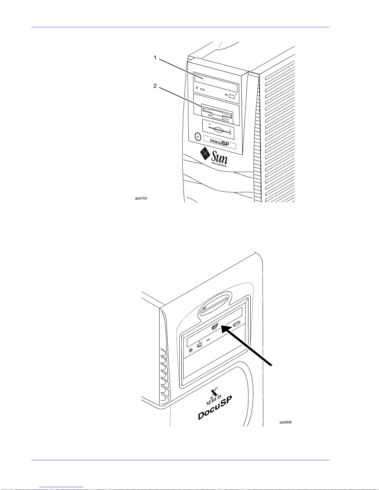
Figure 2-3 Drive locations on the Sun Blade 1000/2000 processor
1. CD drive
2. Diskette drive
2-6 Installat ion Planning Guide
Figure 2-4 DVD/CD-RW drive location on Sun Blade 2500 and Sun
W1100z processor
Page 31

Controller components and options
• Back panel: The back panel of the processor has a power
receptacle and outlet, connectors, connector openings, and
ports. The following figure shows the back panel of the
controller.
Installation Planning Guide 2- 7
Figure 2-5 Back panel of the Sun Blade 1000/2000 controller
1. Access panel lock block
2. Serial connectors A and B, DB-25
3. Parallel connector
4. SCSI connector
5. Universal serial bus (USB) connectors
(for keyboard and for mouse)
6. Twisted-pair Ethernet (TPE) connector
7. IEEE 1394 connectors
8. Fibre Channel-Arbitrated Loop (FC-AL) connector
9. Audio module headphones, line-in, line-out, and
microphone connectors
10. Graphics card / video connector (frame buffer 0)
11. PCI card slot 4
12. Graphics card / video connector (frame buffer not used)
13. PCI card slots 3 and 2
14. Power connector
15. PCI card slot 1
Page 32

Controller components and option s
Figure 2-6 Common back panel of Sun Blade 2500 and Sun W1100z
1. Parallel connector
2. Audio module headphones, line-in, line-out, and
microphone connectors
3. PCI card slots 4 and 5
4. Graphics accelerator
5. PCI card slots 0, 1, and 2
6. External UltraSCSI connector
7. Twisted-pair Ethernet
8. Serial connector
9. USB connectors (The diskette drive may be plugged into
any one of these.)
10. Power connector
Keyboard The keyboard consists of alphanumeric keys similar to a
typewriter, symbols and special character keys, an extended
character set, and function keys. The keyboard is one of your
main methods of communicating with the printer. You can use the
keyboard to make selections, and to enter commands that control
functions such as requesting sample prints, or shutting down the
system.
2-8 Installat ion Planning Guide
Page 33

Controller components and options
Mouse The mouse is another main method of communicating with the
printer.
Display monitor The 17-inch LCD monitor allows you to interact with the printer
and to monitor it s interaction with the various components. During
a print job, printer er ror messages may displa y to notify you of any
unexpected conditions.
Diskette drive The external diskette drive plugs into the back panel of the
processor. Diskettes inserted into a diskette drive are used to
install font s and to load files to, and back up files f rom, the inter nal
disk drive. The diskette drive uses industry st andard 3.5 inch, 1.44
MB, double-sided, high-density diskettes.
Optional processor
components
The controller may be configured with any of the followi ng optional
components:
• Connectivity board to enable Token Ring
• Channel interface board for channel connection to a host for
online LCDS printing
• One SCSI board to connect to an external tape drive
• Graphics board:
– PGx64 (Sun Blade 1000/2000)
– XVR-100 (Sun Blade 2500)
– Creator-3D series 3 graphics board
NOTE: The PGX64 graphics board is provided as a standard
feature of the processor. If more than one connectivity option is
installed, the PGx64 board is repl aced by the Creator3D graphics
board.
Controller interface options
Online interface
Installation Planning Guide 2- 9
Your printing system may be configured for either the online
interface, the offline interface, or both.
The online (channel-attached) interface receives input directly
from any environment that supports the IBM 3211 and 4245 host
systems.
Page 34

Controller components and option s
Tape driv e option
The 36-track cartridge tape drive i s an option. Your printing
system supports the followin g tape drives for offline prin ting and
importing and exporting of resources:
• 9-track open reel tapes
• 36-track cartridge tapes
Figure 2-7 Peripheral cabinet with tape drives
1. 9-track open reel tape drive
2. 18/36-track cartridge tape drive
If you have other Xerox printing systems, you may alread y have a
peripheral cabinet that houses a 9-track open reel and an 18/36track cartridge tape drive. The DocuPrint 100/115/135/155/180
EPS supports existing peripheral cabinets, but the peripheral
cabinet option is not available with new systems.
The following 18-track tape drives are not supported:
• STK 4220 MOD 1 tape drive (3480)
• STK 4220 MOD 2 tape drive (3490)
2-10 Installation Planning Guide
Page 35

3 Printer components and
Printer components
options
The printer processes the page images received from the
controller and produce s the pri nted output. Thi s chap ter descr ibes
the components and options available for the Xerox DocuPrint
100/115/135/155/180 EPS printer.
The standard printer components are the sample tray, the purge
tray, the two processor feeder trays, and the feeder/stacker
module or modules.
The base configuration for the printer includes an inverter feeder/
stacker and one additional feeder/stacker module.
Installation Planning Guide 3-1
Figure 3-1 Printer base components
1. Processor feeder trays
2. Sample tray
3. Attention light
4. Purge tray
5. Feeder/stacker module
6. Inverter feeder/stacker module
NOTE: Some printer configurations may include a control
console (not shown).
The printer provides control buttons and displays for basic printer
functions and status information. Where available, the printer
control console displays messages and graphics that assist you
with jam clearance and printer maintenance. Labels are located
Page 36

Printer components and options
Printer configurations
throughout the printer to assist you with a variety of tasks such as
clearing a paper jam.
Refer to the Xerox DocuPrint 100/115/135/155/180 Enterprise
Printing System Operator Guide for detailed description of the
features and operation of the printer components.
The Xerox DocuPrint 100/115/135/155/180 EPS is available in
several different conf igurations, which allow you to customize the
printing system for increased e fficiency and for specialized
applications.
• Inverter feeder/stacker + 1 feeder/stacker
• Inverter feeder/stacker + 2 feeder/stackers
• Inverter feeder/stacker + 3 feeder/stackers
These configurations are illustrated below.
Figure 3-2 Printer with inverter feeder/stacker and
one feeder/stacker
Figure 3-3 Printer with inverter feeder/stacker and
two feeder/stackers
3-2 Installat ion Planning Guide
Page 37

Figure 3-4 Printer with inverter feeder/stacker and
Bypass transport option
The bypass transport option provides an interface between the
DocuPrint 100/115/135/155/180 EPS and your finishing
accessories. However, finishing devices require separate power
sources that are independent of the printing system.
The bypass transport optio n enables third party finishing devi ces
to interface directly with t he pr inti ng system. The bypass transport
allows you to customize your printer for increased efficiency and
specialized applications i n volving finishing.
Printer components and opti ons
three feeder/stackers
Function of the
bypass transport
Paper stocks
supported on
bypass transport
Bypass transport
printer
configurations
NOTE: A bypass transport must be installed for the printing
system to support a third party finishing device.
Connected to the last feeder/st acker module, the bypass transport
moves paper from the stacker to a third party finisher such as a
stitcher, booklet maker, tape binder, and so on. By making
selections on the user interface windows, you can program the
printer to send output to the byp a ss transport, which direct s the
output to the finishing equipment.
The bypass transport a ccepts all paper stocks on which the prin ter
can print, and it accommodates simplex and duplex printing.
The following printer configurations may have the bypass
transport, illustrated below:
• Printer with inverter feeder/stacker and 1 feeder/stacker
• Printer with inverter feeder/stacker and 2 feeder/stacker s
Installation Planning Guide 3- 3
Page 38

Printer components and options
Figure 3-5 Printer with inverter feeder/stacker,
one feeder/stacker, and bypass transport
Figure 3-6 Printer with inverter feeder/stacker,
two feeder/stackers, and bypass transport
Roll feeder support (DP155 and DP180 EPS only)
The roll feeder option may be installed in the inverter feeder/
stacker module, replacing the feeder tray. This option does not
require DFA or input enablement software, or any additional
hardware.
The maximum number of feeder/stacker modules supported for
this configuration is four, including the inverter module with the roll
feeder. With the two processor feeder trays, this makes a total of
six input trays possible.
3-4 Installat ion Planning Guide
Page 39

4 Prep aring for installation
This chapter assists you in preparing for the installation of your
Xerox DocuPrint 100/115/135/155/180 EPS. Use this chapter in
conjunction with the Getting Ready for Installation manual.
Preparing for inst alla tion is a responsibi lity shar ed by perso nnel at
your site and Xerox. Your Xerox representatives are available to
discuss installation issues and to assist you in completing the site
installation tasks.
Before installation, you must select and prepare an appropriate
location for the printing syst em and order supplies. This chapter
helps you accomplish these tasks by providing the following
information:
• A summary of your responsibilities and those of your Xerox
service representative
• A checklist of installation planning activities.
For information on contr oller power and spa ce requirement s, r efer
to the “Controller specific ations and requirements” chapter of thi s
guide. For facts about printer power and space requirements,
refer to the “Printer specifications and requirements” chapter of
this guide.
Responsibilities
This section describes your site responsibilities and the
responsibilities of your service representatives. Some joint
responsibilities are included.
Installation Planning Guide 4-1
Page 40

Preparing for installation
Xerox responsibilities
This section list s the respon sibili ties of t he service r epresent atives
and systems analysts before, duri ng, and after installati on:
• Site selection
– Assist in site selection
– Inspect and approve the site
• Installation
– Schedule the delivery of the hardware
– Monitor installation activities
– Assist you in ordering any supplies requi red
– Install the printing system
– Install LCDS system resource files, if applicable
•Training
– Provide initial operator training
– Provide information an d assist ance in regi stering for Xe rox
Customer Education classes
• Service
– Review preventive maintenance schedules and service
call procedures
– Provide ongoing maintenance
– Assist in resolving hardware and software problems
– Obtain software licenses as appropriate
Customer responsibilities
Your responsibilities before, during, and after inst allation of the
DocuPrint printing system are to schedule and monitor your
installation activities. Refer to the installation planning checklist in
this chapter for a complete list of responsibilities.
Refer to the “Xerox support services” appendix for information on
services designed to support you before, during, and after your
installation.
NOTE: Operating system software is not the same for all printing
systems. Therefore, make sure that your system specialists are
familiar with the operating syst em software that is specifi c to your
DocuPrint system. If your system specialists are familiar with one
operating systems and you are converting to, or adding another,
they should be familiar with the differences.
Site personnel Identify the person (or persons) at your site who will be the
4-2 Installat ion Planning Guide
primary interface with Xerox.
Page 41

Preparing for inst allation
After the installation of the printing system, there are a few
ongoing tasks that must be performed. These tasks may include
all or some of the following:
• Meter reading and reporting
• Overseeing routine maintenance
• Placing service calls for hardware problems
• Ordering additional documentation, software, or fonts
• Arranging additional operator training
• Maintaining an adequate inventory of consumable supplies.
It is your responsibility to designate a person (or persons) to
perform these tasks.
Operator and
systems training
Site preparation Select and prepare the site for system installation (including
Network install ation Install the necessary network components required to connect
Channel-attached
printing
Client workstations Make sure all client workstations that will be submitting print jobs
Applications Work with your Xerox systems analyst to determine requi rements
Select personnel for operator and systems training and set up a
training schedule.
proper power, air conditioning, and work space). If connecting to
other equipment, obtain the necessary interfaces, cables,
transceivers, phone lines, and so forth.
client workstations to the printing system. Refer to the Getting
Ready for Installation manual for details.
Obtain and install fully populated bus and tag cables required to
connect the host to the printing system. Refer to the Getting
Ready for Installation manual for details.
have the proper hardware, operating system, and networking
software required by the print ing system as client platforms.
for initial applications.
Installation planning checklist
Installation Planning Guide 4- 3
To aid you in planning for printer installation, the following
checklist contains the tasks that you and your service
representative must complete before installation. If you have
questions about any of these activities, contact your sales or
service representative.
Use the time frames in this checklist as guidelines. It is best to
consult your suppliers to determine the required lead times.
Page 42

Preparing for installation
Table 4-1 Installation planning checklist
Week Activity Responsibility
Date
completed
-4 • Select location for the printing system.
• Order additional sets of documentation, as
necessary.
• Register for Xerox Customer Education classes
and order tutorials, as necessary.
• Schedule printer delivery.
-3 • Schedu le har dwa re deliver y.
• Prepare site:
• Ensure proper electrical outlets are installed.
• Install network to system location, if applicable.
• Install channel to system location, if applicable.
Cables must be fully populated.
• Ensure proper operating environment.
-2 • Inspect and approve site.
• Order consumable supplies. Minimum supplies
needed for installation:
• Pa per (2 cartons )
• Developer (1 carton)
• Fuser agent (2 boxes)
• Dry ink (1 carton)
• After installation, you will need to establish a
procedure for ordering supplies according to
your ongoing production requirements.
Customer
Customer
Customer and Xerox
Xerox
Customer and Xerox
Customer
Xerox
Customer and Xerox
_________
_________
_________
_________
_________
_________
_________
_________
_________
_________
_________
-1 • Schedu le oper a tor trainin g. Customer and Xerox _________
Install Ensure supplies are available.
Ensure system administrators are available during
Customer
Customer
_________
_________
software installation.
Provide applicable completed worksheets from the
Customer
_________
Getting Ready for Installation document.
If the NPS/IPS Extension option is being installed,
provide applicable information as directed in the 96/
4635/180 NPS/IPS Installation Pl ann ing Guid e.
Install printing system hardware and software.
Have operators available for training.
Check documentation and software kits for
completeness.
Xerox
Customer
Customer
_________
_________
_________
Have test jobs ready to run.
Provide stocks needed fo r default input
configuration.
Customer
Customer
_________
_________
Obtain and enable software license.
Customer
_________
4-4 Installat ion Planning Guide
Page 43

Preparing for inst allation
Week Activity Responsibility
Date
completed
Post-install Become familiar with support services available.
Establish supplies maintenance procedure.
Provide ongoing system maintenance.
Adjust the printer alignment and magnification.
Order additional documentation, as necessary.
.
Connectivity requirements
An Ethernet local area network (LAN) running Transmission
Control Protocol/Internet Protocol (TCP/IP), AppleTalk, or Novell
NetWare software is the network communication system used to
transport documents from the client workstation to the printing
system.
Ethernet specifications
Customer
Customer
Customer and
Xerox
Xerox
Customer
_________
_________
_________
_________
_________
The Ethernet connection to the controller processor must be
compatible with the Institute of Electrical and Electronics
Engineers (IEEE) 802.3 standard.
The Ethernet interface on the controlle r processor is a 10 Mb/sec
twisted pair standard (10BaseT, 100BaseT, and 1000BaseT).
Attachment Unit Interface (AUI) Coax Ethernet is enabled with an
adapter cable.
Work with your system administrator to assess what type of
network you have and what modifications need to be made to
supply an Ethernet connector to the controller processor.
Token Ring specifications
Users of network client workstations may send print jobs to the
printer using TCP/IP, Novell 3.x, or Apple Talk network protocol.
The Token Ring connection to the controller processor must be
compatible with the Institute of Electrical and Electronics
Engineers (IEEE) 802.3 standard.
The controller processor has a 4 MB or 16 MB Token Ring Auto
interface (16 MB is preferred).
Installation Planning Guide 4- 5
Page 44

Preparing for installation
Channel-attached specifica tions
For an online configuration with an I BM host system, t he foll owing
cables must be available:
• Bus and tag cables (bus in, bus out, t ag in, tag out)
• Terminators (as necessary, due to location on channel).
For your convenience, you may be able to order the bus and tag
cables through Xerox on a purchase-only basis. Cont act your
Xerox sales representative for availability, current pricing, and
order information.
4-6 Installat ion Planning Guide
Page 45

5 Controller requirements
Power requirements
and specifications
This chapter provides power and space requirements for the
controller. It also provides controller environmental specificati ons.
For facts about pri nter power and s pace requirement s, refer to the
“Printer specifications and requi rements” chapter of this guide.
Your controller has important power requirements that must be
accommodated. These requirements are summarized in the table
below.
For details on printer power requirements, refer to the “Printer
specifications and requirements” chapter of this guide.
Table 5-1 Controller electrical requirements
Sun and
Sun Blade
controller
60 HZ 100 to 240
50 HZ 100 to 240
Table 5-2
Agency certification: UL 1950, IEC 950, CSA 22.2 #950-1950,
FCC (Class A), and EN 55022: 1998 (Clas s A), and EN 61000-3 -2
(or EN 61000-4-2,3,4,5,6,8,11): 1995 + A1-1998 + AZ 1998,
EN6100-3-3: 1995 and EN 55024: 1998.
Outlet configurations
Voltage Amp service KVA rating NEMA
15 amp 0.4 KVA 5-15R
VAC
15 amp 0.4 KVA N/A
VAC
Installation Planning Guide 5-1
This section discusses specific ations for system outlets and the
required wall outlet configurations f or the USA / Canada and
internationally.
Page 46

Controller requirements and specifications
N
USA/Canada
Supply
NOTE: All power outlets must be dedicated to this equipment.
When determining the electrical connections for printing system,
make sure that:
-Each power cord has a separate circuit.
-The printer power cord configurati ons match your receptacle.
-Your electrical outlets are within the required specifications.
50 Hz systems: Ensure that power connections are per local
codes/regulations.
The following figure shows American, Canadian, and European
wall outlets in which to plug the controller.
NOTE: The optional 9 track and 18/36 track tape drives each
require an outlet identical to the one that is shown for the
controller.
AC Neutral
(ACN)
eutral
AC Hot (ACH)
Earth Ground (GND)
United Kingdom
Europe
Earth
Earth
Live
Figure 5-1 Multinational wall outlet c onfigurations
The required wall outlet voltages for USA / Canada, United
Kingdom, and the rest of Europe are as follows:
5-2 Installat ion Planning Guide
• USA / Canada: The voltage at the wall outl et is 100 to 120
VAC between AC hot and neutral, and between AC hot and
GND. The voltage is less than three VAC between GND and
neutral.
• United Kingdom: The voltage at the wall receptacle is 200 to
240 VAC between live and neutral, and between live and
earth. The voltage is less than three VAC between earth and
neutral.
• Europe: The voltage at the wall recept acle is 200 to 240 VAC
between supply pins. The volt age be tween one suppl y pin and
Page 47

earth is 200 to 240 VAC. The voltage between the other
supply pin and earth is less than 3 VAC.
Refer to the controller electrical requirements table earlier in this
chapter for a description of the power specifications for the
controller.
WARNING: To reduce the risk of electrical shock, do not plug
components into any other type of power system. Contact your
facilities manager or a qual ified el ectrician i f you are not sure what
type of power is supplied to your work area.
Environmental specifications
The controller is a sturdy piece of equipment; however, like any
piece of electronic equipment, it must be treated properly. Avoid
extremes in temperature and other environmental hazards. Place
the controller in a rel ativel y du st-fr ee ar ea that i s well -venti lated t o
avoid overheating.
Controller requirements and specifications
Space requirements
Controller placement
In general, if your wor king envi ronment i s comfor t abl e fo r yo u, it is
suitable for your controller. The following sections define the
acceptable environmental ranges for the controller models with
which your system may be configured.
For recommended environmental ran ges for the pri nter work area,
refer to the “Printer specifications and requirements” chapter of
this guide.
This section provides recommendations for placement of
controller hardware components.
For printer component space requirements, refer to the “Printer
specifications and requirements” chapter of this guide. Cont act
your service representative if you have questions not specificall y
addressed in this guide.
Installation Planning Guide 5- 3
WARNING: The controller must be positioned within the line-ofsight of the printer for safety purposes while servicing the
equipment.
The controller components are place d in the accompanying
controller stand. You should consider the following factors when
deciding where to place the controller and stand:
• There should be at least 36 inches / 15.2 cm of clearance on
Page 48

Controller requirements and specifications
all sides of the controller stand.
• Adequate work space and service clearance around the
equipment
• Proximity to electrical and network connectors
• Security of the work area. You may need to place the system
in an area where you can restrict access to it.
Guidelines for controller placement
To ensure consistent performance and avoid any damage to
equipment, follow these rules for placi ng the components of the
controller.
Do:
• Use the controller stand that comes with your printing system
equipment.
• Allow at least 6 inches / 152 mm of unobstructed space at the
front and rear of the processor, so the fan and vents are not
blocked.
The following illustration shows fa n and vent locations on the
front and back of the processor.
Do not:
• Place the monitor and processor on a desk or table top.
• Do not place the monitor on top of the processor.
• Do not allow any piece of equipment to blow warm air into the
air intake vents of the pr ocessor.
• Do not place the processor on its side, or i n any other posit ion
but the upright, vertical position achieved by using the
controller stand.
• Do not place the processor or monitor on top of the printer.
Controller hardware specifications and requirements summary
For a summary of printer hardware specifications and
requirements, refer to the “Printer specifications and
requirements” chapter of this guide. Contact your local Xerox
representative if you have questions not specifically addressed in
this guide.
5-4 Installat ion Planning Guide
Page 49

6 Printer requirements and
Power requirements
specifications
This chapter provides power and space requirements for the
DocuPrint 100/115/135/155/180 EPS printer. It also provides
printer environmental specifications.
For information about controller power and space requirements,
refer to the “Controlle r specification s and requirement s” chapter of
this guide.
Your printer has important power requirements that must be
accommodated. These requirements are summarized in the table
below.
For further details on power requirements, refer to the voltage
charts and wiring diagrams that follow.
For details on controller power requirements, refer to the
“Controller specifications and requirements” chapter of this guide.
Table 6-1 Printer electrical requirements
Component Voltage Amp. service
Printer 60 Hz
(U.S. and
Canada)
Printer 50 Hz WYE (Star)
120/240 VAC or 120/
208 VAC (Cord 1)
120/240 VAC or 120/
208 VAC (Cord 2 for DP
155 and DP180 only)
380, 400, 415 VAC
(3 phase, 5 wire)
50 amp (Cord 1)
30 amp (Cord 2 for
DP 155 and DP180
only)
30 amp Consult local
Agency certification: UL 478 and 1950, IEC 950, CE Mark,
CSA 22.2 #220-1986, FCC (Class A), and VDE 0871 (Class A).
KVA rating
(operating mode)
Operating: 7.3
+ .75 per middle
module stacker
service
representative
Additional
Requirements
14-50R (Cord 1)
14-30R (Cord 2
for DP 155 and
DP180 only)
Installation Planning Guide 6-1
Page 50

Printer requirements and specifications
Outlet configurations
This section discusses specifications for printer outlets and the
required wall outlet configurations f or the USA / Canada and
internationally.
NOTE: All power outlets must be dedicated to this equipment.
When determining the electrical con nections for your pri nter , make
sure that:
a) Each power cord has a separate circuit
b) The printer power cord configurations match your receptacle
c) Your electrical outlets are within the required specifications
50 Hz systems: Ensure that power connections are per local
codes/regulations.
60 Hz printer outlet voltages
Printer power outlet
and cord voltage
configurations–
60 Hz
The following table shows the voltages for the outlets on your
printer. All power outlets must have a dedicat ed circuit for each
system equipment piece. Make sure each power cord has a
separate circuit .
Table 6-2 Printer (60Hz) voltage requirements at power outlet
Service outlet
configuration
4 Wire Line 1 to neutral 120 V RMS 107-127 V RMS
4 Wire Line 2 to neutral 120 V RMS 107-127 V RMS
4 Wire Neutral to ground 0 0-10 V RMS
4 Wire Line 1 to line 2 208 V RMS 182-220 V RMS
4 Wire Line 1 to line 2 240 V RMS 210-254 V RMS
Measurement of
wiring
Nominal Range
The following figures shows the 60 Hz power outlet configuration
for 50 amp NEMA 14-50R and 30 amp NEMA 14-30R. Voltage to
ground is shown for troubleshooting purposes.
6-2 Installat ion Planning Guide
Page 51

Printer requirements and speci fications
NEMA
14-50R
Figure 6-1 60 Hz power configuration–50 amp
NEMA
14-30R
Figure 6-2 60 Hz power configuration–30 amp
50 Hz printer outlet voltages
All power outlets must have a dedicated circuit for each system
equipment piece. Make sure each power cord has a separate
circuit.
NOTE: Consult with your service representati ve to ensur e that the
installation conforms to your local electrical req u irements.
WYE (or Star )
configurations–
50 Hz
For the 50 Hz WYE configuration, measure the WYE or Star
connection voltages at the power source.
Installation Planning Guide 6- 3
Page 52

Printer requirements and specifications
Table 6-3 Printer (50 Hz) WYE (Star) 415 voltage
Service outlet
configuration
5 Wire 415 V Line 1 to line 2 415 V RMS 374-457 V RMS
5 Wire 415 V Line 2 to line 3 415 V RMS 374-457 V RMS
5 Wire 415 V Line 1 to Line 3415 V RMS 374-457 V RMS
5 Wire 415 V Line 1 to
5 Wire 415 V Line 2 to
5 Wire 415 V Line 3 to
Measuremen
t of wiring
neutral
neutral
neutral
Nominal Range
240 V RMS 216-264 V RMS
240 V RMS 216-264 V RMS
240 V RMS 216-264 V RMS
The following lists the 50 Hz WYE/Star printer outlet information
for 380 and 400 volts.
Table 6-4 Printer (50 Hz) WYE (Star) 380 and 400 voltage
Service outlet
configuration
Measurement
of wiring
Nominal Range
Printer power outlet/
cord voltage
configurations–
50 Hz
5 Wire 380 V Line 1 to line 2 380 V RMS 342-419 V RMS
5 Wire 380 V Line 2 to line 3 380 V RMS 342-419 V RMS
5 Wire 380 V Line 1 to Line 3 380 V RMS 342-419 V RMS
5 Wire 380 V Line 1 to neutral 220 V RMS 198-242 V RMS
5 Wire 380 V Line 2 to neutral 220 V RMS 198-242 V RMS
5 Wire 380 V Line 3 to neutral 220 V RMS 198-242 V RMS
5 Wire 400 V Line 1 to line 2 400 V RMS 358-438 V RMS
5 Wire 400 V Line 2 to line 3 400 V RMS 358-438 V RMS
5 Wire 400 V Line 1 to Line 3 400 V RMS 358-438 V RMS
5 Wire 400 V Line 1 to neutral 230 V RMS 207-253 V RMS
5 Wire 400 V Line 2 to neutral 230 V RMS 207-253 V RMS
5 Wire 400 V Line 3 to neutral 230 V RMS 207-253 V RMS
For 50 Hz systems outlet/power cord configurations, consult your
local service representative to determine the type of plug and
receptacle to use.
6-4 Installat ion Planning Guide
Page 53

Environmental specifications
When you select a location for your printer, avoid environments
with extreme variations in temperature and other hazards, such as
excessive dust or humidity. Recommended environmental ranges
for the work area are as follows:
Table 6-5 Printer environmental specifications
Condition Range
Printer requirements and speci fications
Operating
temperature
Recommended:
Minimum:
Maximum:
Humidity Recommended:
Minimum:
Maximum:
Altitude: Normal:
Maximum:
Heat
dissipation:
Operating:
DP 155 and
180 (2-stacker
Standby:
Energy Saver:
system)
Operating:
DP 100, 115,
and 135
Standby:
Energy Saver:
(2-stacker
system)
68° F to 76° F / 20° C to 24° C
50° F / 10° C
85° F / 29° C
45% ±10%
30%
65%
Up to 6,000 feet / 1,830 m
above sea level
9,000 feet / 2,743 m above
sea level
32,770 BTU/hour
4,454 BTU/hour
2,700 BTU/hour
28,140 BTU/hour
4,454 BTU/hour
2,700 BTU/hour
Space requirements
Installation Planning Guide 6- 5
Audible noise Operating:
Continuous:
82 dB(A)
82 dB(A)
Impulse:
Standby:
Continuous:
Impulse:
52 dB(A)
N/A
You should consider the following factors when deciding where to
place the printer hardware components:
• Adequate work space and service clearance around the
equipment
Page 54

Printer requirements and specifications
• Proximity to electrical and network connectors
• Security of the work area. You may need to place the system
in an area where you can restrict access to it. This may be
important if your personnel need to print confidential
documents or if you are concerned with unauthorized usage.
Dimensions and weights of the printer components are listed in
this section, along with diagrams, to help you visualize the sizes
and total space requirements.
NOTE: There must be a 78 inch / 198 cm vertical clearance
throughout the entire area. In additi on, your printer must be
installed in a fixed location with a minimum clearance space of 36
inches / 91.4 cm around all sides of each piece of equipment for
access by service personnel. In addition, there must be 50 inches
/ 126.9 cm clearance space in front of the printer.
For information on clearance space and other space planning
considerations, refer to the “Space planning gu idelines” section of
this chapter. Contact your service representative if you have
questions not specifically addressed in this guide.
Printer configurations available
The following configurations are available for the printer:
• Printer + inverter feeder/stacker + 1 feeder/stacker
• Printer + inverter feeder/stacker + 2 feeder/stackers
• Printer + inverter feeder/stacker + 3 feeder/stackers.
Measurements and a top-view diagram for each of these
configurations is provided on the follo wing pages.
Printer configuration diagrams
The following diagrams show sp ace requi r ements for three p rinter
configurations.
Printer wi th
inverter feeder/
stacker and
one feeder/stacker
The dimensions of the printer with the inverter feeder/stacker and
feeder/stacker are as foll ows:
• Width: 151.25 inches / 384.2 cm
• Depth: 38.8 inches / 98.6 cm
6-6 Installat ion Planning Guide
• Height: 59.6 inches / 151.3 cm
• Weight: 2,588 pounds / 1174.9 kg
• Total space requirement: 223.25 by 114 inches / 567 by 290.3
cm
Page 55

Printer requirements and speci fications
Printer wi th
inverter feeder/
stacker and
two feeder/stackers
Figure 6-3 Printer with inverter feeder/stacker and
one feeder/stacker (top view)
1. Printer
2. Back of printer area
3. Inverter feeder/stacker
4. Feeder/stacker
5. Front of printer area
The dimensions of the printer with t he i nverter feeder/ st acker, and
two feeder/stackers are as follows:
• Width: 183.50 inches / 466.1 cm
• Depth: 38.8 inches / 98.6 cm
• Height: 59.6 inches / 151.3 cm
• Weight: 3,109 pounds / 1,411.9 kg
• Total space requirement: 114 by 256.50 inches / 290.3 by
648.9 cm
Installation Planning Guide 6- 7
Page 56

Printer requirements and specifications
Printer wi th
inverter feeder/
stacker and
three feeder/
stackers
Figure 6-4 Printer with inverter feeder/stacker and two feeder/
stackers (top view)
1. Printer
2. Back of printer area
3. Inverter feeder/stacker
4. Feeder/stacker
5. Feeder/stacker
6. Front of printer area
The dimensions of the printer with the inverter feeder/stacker and
three feeder/stackers are as follows:
• Width: 215.75 inches / 548 cm
• Depth: 38.8 inches / 98.6 cm
• Height: 59.6 inches / 151.3 cm
• Weight: 3,630 pounds / 1,648.9 kg
• Total space requirement: 114 by 287.75 inches / 290.3 by
730.8 mm
6-8 Installat ion Planning Guide
Page 57

Printer requirements and speci fications
Figure 6-5 Printer with inverter feeder/stacker and three feeder/
stackers (top view)
1. Back of printer area
2. Printer
3. Inverter feeder/stacker
4. Feeder/stacker
5. Feeder/stacker
6. Feeder/stacker
7. Front of printer area
Bypass transport specifications
The bypass transport optio n enables you to add a third-party
finishing device. The bypass transport is installed by your service
representative and remains permanen tly in place. You should not
attempt to remove or reinstall it . The following is
supported by the bypass transport:
• Paper size and weight: You can use all of the paper sizes
and weights supported by the printer in the bypass transport.
Installation Planning Guide 6- 9
• Sheet exit orientation: 1 to N (the same order in which
sheets are fed from the printer), delivered face down.
• Maximum throughput speed: The bypass transport for the
printer supports throughput speeds of up to 180 ppm (pages
per minute). This rate is based on stocks up to 9 by 14.33 /
229 by 364 mm in length.
• Sheet exit height: 34 inches / 86 cm above the floor.
Page 58

Printer requirements and specifications
Bypass transport dimensions
The following pages contain diagr ams showing dimensions,
service access, and the paper path for the bypass transport.
Dimensions The following figure shows the dimensions of the bypass tr ansport
in millimeters and inches from the right end view.
6-10 Installation Planning Guide
Figure 6-6 Bypass transport dimensions
Page 59

Printer requirements and speci fications
Service access The following figure provides space planning information and
service access requirements for the bypass transport.
Figure 6-7 Bypass transport space planning diagram (top view)
1. Recommended third-party feeder hardware attaches at rear
of printer
2. Expected third-party input paper feed path
3. Neutral area, to remain unoccupied
4. Shaded areas at rear and right side of the bypass transport
require third-party input/output devices to be undockable
from the feeder/stacker or the bypass transport
5. Register edge of the output sheet
6. Third-party hardware must not extend more than 1 inch /
25 mm beyond bypass transport front cover line for cor rect
front door access
7. Bypass transport / input enablement jam clearance space is
required
Bypass transport
paper path
The following figure shows the paper path through the bypass
transport from a front view.
Installation Planning Guide 6-11
Page 60

Printer requirements and specifications
Figure 6-8 Bypass transport paper path
Configuration diagrams with bypass transport
The following diagrams show the dimensions and space
requirements of the printer with a bypass transport. These
diagrams represent top views of the components, surrounded by
the minimum access space requirements on all sides.
6-12 Installation Planning Guide
Page 61

Printer requirements and speci fications
Figure 6-9 Printer—inverter feeder/stacker and
one feeder/stacker with bypass transport
1. Printer
2. Inverter feeder/stacker
3. Back of printer area
4. Feeder/stacker
5. Bypass transport
6. Front of printer area
Installation Planning Guide 6- 13
Page 62

Printer requirements and specifications
Figure 6-10 Printer—inverter feeder /st ack er and
1. Printer
2. Inverter feeder/stacker
3. Back of printer area
4. Feeder/stacker
5. Feeder/stacker
6. Bypass transport
7. Front of printer area
Space planning guidelines
When determining your space requirements and planning for
shared space between your printers, it is important to consider all
of the components you plan to install.
To ensure all of the space requirements are met, it is important to
work with your Xerox representative.
Before installation, you must consider the following:
• Clearance space requirements where you intend to install the
printer
two feeder/stackers with bypass transport
6-14 Installation Planning Guide
• Recommended cable lengths and locations (refer to the
“System connections” chapter of this guide for more
information)
• Delivery access requirements
Page 63

• Floor leveling
Clearance space requirements
The printer must be installed in a fixed location that provides the
following clearance space:
• 36 inches / 91.4 cm on all sides of each component
• 78 inches / 198 cm of vertical clearance throughout the entire
area
• 24 inches / 61 cm of exclusive operator area in front of each
component
NOTE: There must be a total of 50 inches / 126.9 cm of c learance
space in front of the printer.
Shared space between component s
Printer requirements and speci fications
It is best to provide the full amount of clearance space around the
hardware components. Your environment may require you to use
shared space between components such as between the pri nter
and the controller or between the printer and another Xerox
printing system. You can share the 36-inch / 91.4 cm clearance
space around each component, as long as you follow these rules:
• Space may be shared only with other Xerox equipment.
• Components may share the 36-inch / 91.4 cm general service
clearance areas, but they may not share the 24-inch / 61 cm
operator area in front of each component.
• There must be 78 inches / 198 cm of vertical clearance
throughout the entire area.
NOTE: Finishers that are attached to your bypass transport may
occupy shared space with Xerox equipment. However, they must
be removable to allow servicing of the printer feeders and
stackers. Consult with your Xerox representative to ensure all the
requirements are met.
Shared space configuration diagrams
The following figures illustrate three possible configurations of
shared space.
Back-to-back
shared space
Installation Planning Guide 6- 15
The figure below illustrates the two prin ters placed in a back-toback position. This allows the printe rs to share the entire 36
inches /
91.4 cm of general service space.
Page 64

Printer requirements and specifications
Face-to-face
shared space
Figure 6-11 Back-to-back shared service area space
1. Operat or area
2. Printer
The following figure shows the two printe rs f acing eac h othe r. The
printers share 26 inches / 30.5 cm of the general se rvice space,
but not the exclusive operator area in fron t of each printer.
Therefore, the printers should be separated by 24 inches / 61 cm,
plus 24 inches / 61 cm, plus 26 inches / 30.5 cm. This allows for
the entire operator spa ce fo r each printe r, plus the shared general
service area of 26 inches / 30.5 cm.
6-16 Installation Planning Guide
Page 65

Printer requirements and speci fications
Face-to-face
shared space
Installation Planning Guide 6- 17
Figure 6-12 Face-to-face shared service area space
1. Operat or area
2. Printer
The following figure shows the two printers arranged wit h one
facing the back of the other. Between them is 60 inches / 152.4 cm
of space. This allows for 24 inches / 61 cm of operator space in
front of the printer facing toward the other, plus 36 inches / 91.4
cm of service space behind the printer facing away from the other.
Page 66

Printer requirements and specifications
Floor leveling
6-18 Installation Planning Guide
Figure 6-13 Face-to-back shared space
1. Operat or area
2. Printer
For proper operation, the printer must be perfectly level. On floors
less than two degrees out of level, installation personnel use a
leveling kit to level the machine.
NOTE: The printer will not function properly on floors more than
two degrees out of level.
If the floor is more than two degrees out of level, find another
location for the printer.
Page 67

For your reference, two degrees represents a height discrepancy
of approximately 3.8 inches / 9.6 cm measur ed at t he caster s with
the printer tilting from lef t to right, or appr oximately 0.7 inches / 1.8
cm with the printer tilting from back to fr ont.
If you move the printer after its initial installation, it is your
responsibility to make sure that the pr inter can be leveled properl y .
If you do not have the leveling kit (the printer in its initial location
did not require it), and you need one to level the printer in a new
location, contact your Xerox site representative to
obtain one.
Delivery access requirements
It is easy to overlook the path required to move the equipment
from the truck to the operation site. To determine access, ask the
following questions:
• Does the equipment need to go up or down a stairwell? How
wide is the stairwell?
Printer requirements and speci fications
• Do you have an elevator, if the equipment is to be located
above or below the first floor?
• Is the elevator large enough for the equipment?
• How wide are the hallways and doorways?
• Do you have a loading dock or a specific door to which the
equipment should be delivered?
You need to review these issues before or during the site
inspection conducted by your service representative.
The equipment dimensions are speci fied e arli er i n thi s chapter, so
it is easy to determine whether your hallways and doorways are
wide enough to permit access.
Turning radius
You must also consider the width of the passageway when the
equipment must negotiate a corner, whether into a room, an
elevator, or another passageway.
There are L-shaped turns and T-shaped turns. The diagrams and
the tables that follow show the minimum space required to
maneuver through the turns.
Installation Planning Guide 6- 19
Page 68

Printer requirements and specifications
Figure 6-14 L-shaped turn
Passage 1
Passage 2
Using the turning
radius tables
Turning radius for
printer wi th
separated
components
Figure 6-15 T-shaped turn
Passage 1
Passage 2
To use the tables:
1. Measure the minimum width of the passage or doorway you
need to use. This is Passage 1.
2. Find that number (or the next higher number) in the turning
radius table and read across to the correspondi ng minimum
value for Passage 2, depending on the type of turn the
equipment must negotiate.
The printing system is delivered with the printer, inverter feeder/
stacker, and each feeder/stacker as separate modules. If
necessary , the printe r can be sep arated in to two pieces fo r ease in
moving. The larger of the two parts contains the xerographic
system; the smaller of the parts (the paper handling module, or
PHM) contains paper trays 1 and 2. Do not confuse these two
parts of the printer with the inverter and feeder/stacker modules,
which have their own turning requirements.
The following table lists the turning requirements for the printer
without the PHM (separated)
6-20 Installation Planning Guide
Page 69

Printer requirements and speci fications
Table 6-6 Turning radius for printer
Passage or doorway 1 width Minimum passage 2 width
29 inches / 73.7 cm 74.5 inches / 189.2 cm
30 inches / 76.2 cm 64.5 inches / 163.8 cm
31 inches / 78.7 cm 62 inches / 157.5 cm
32 inches / 81.3 cm 59.5 inches / 151.1 cm
34 inches / 86.4 cm 56 inches / 142.2 cm
36 inches / 91.4 cm 53 inches / 134.6 cm
38 inches / 96.5 cm 50 inches / 127 cm
40 inches / 101.6 cm 48 inches / 121.9 cm
42 inches / 106.7 cm 45.5 inches / 115.6 cm
The following table list s the tur ning requ irement s for the pri nter if i t
is upended for easier moving or stair-cl imbing. This table reflects
requirements for the printer separated from the PHM
Turning radius for
unseparated
printer components
Table 6-7 Turning radius for printer (separated and upended on
dolly)
Passage or doorway 1 width Minimum passage 2 width
30 inches / 76.2 cm 49 inches / 124.5 cm
31 inches / 78.7 cm 43 inches / 109.2 cm
32 inches / 81.3 cm 41 inches / 104.1 cm
34 inches / 86.4 cm 37.5 inches / 95.3 cm
36 inches / 91.4 cm 35 inches / 88.9 cm
38 inches / 96.5 cm 33.5 inches / 85.1 cm
40 inches / 101.6 cm 32 inches / 81.3 cm
42 inches / 106.7 cm 31 inches / 78.7 cm
The following table lists the turning requirements for the printer
when attached to the paper handling module (not separated).
Installation Planning Guide 6- 21
Page 70

Printer requirements and specifications
Table 6-8 Turning radius for printer (not separated)
Passage or doorway 1 width Minimum passage 2 width
29 inches / 73.7 cm 83 inches / 210.8 cm
30 inches / 76.2 cm 76 inches / 193 cm
31 inches / 78.7 cm 73 inches / 185.4 cm
32 inches / 81.3 cm 70.5 inches / 179.1 cm
34 inches / 86.4 cm 66.5 inches / 169 cm
36 inches / 91.4 cm 63.5 inches / 161.3 cm
38 inches / 96.5 cm 61.5 inches / 156.2 cm
40 inches / 101.6 cm 58 inches / 147.3 cm
42 inches / 106.7 cm 55 inches / 139.7 cm
Turning radii for
feeder/stacker
modules
The following table lists the turning requirements for the inverter
feeder/stacker module.
Table 6-9 Turning radius for inverter feeder/stacker module
Passage or doorway 1 width Minimum passage 2 width
29 inches / 73.7 cm 43 inches / 109.2 cm
30 inches / 76.2 cm 41 inches / 104.1 cm
31 inches / 78.7 cm 40 inches / 101.6 cm
32 inches / 81.3 cm 38 inches / 96.5 cm
33 inches / 83.8 cm 37 inches / 94 cm
34 inches / 86.4 cm 36 inches / 91.4 cm
35 inches / 88.9 cm 35 inches / 88.9 cm
36 inches / 91.4 cm 34 inches / 86.4 cm
37 inches / 94 cm 33 inches / 83.8 cm
38 inches / 96.5 cm 32 inches / 81.3 cm
6-22 Installation Planning Guide
39 inches / 99.1 cm 31 inches / 78.7 cm
40 inches / 101.6 cm 31 inches / 78.7 cm
41 inches / 104.1 cm 30 inches / 76.2 cm
42 inches / 106.7 cm 29 inches / 73.7 cm
43 inches / 109.2 cm 29 inches / 73.7 cm
NOTE: These figures are based on inverter/feeder/stacker
dimensions of 28 inches / 711 mm by 42 inches / 1,067 mm.
Page 71

Printer requirements and speci fications
The following table lists the turning requirements for the feeder/
stacker module.
Table 6-10 Turning radius for feeder/stacker module
Passage or doorway 1 width Minimum passage 2 width
29 inches / 73.7 cm 33 inches / 83.8 cm
30 inches / 76.2 cm 32 inches / 81.3 cm
31 inches / 78.7 cm 31 inches / 78.7 cm
32 inches / 81.3 cm 30 inches / 76.2 cm
33 inches / 83.8 cm 29 inches / 73.7 cm
NOTE: These turning figures are based on inverter/feeder/stacker
dimensions of 28 inches / 71.1 cm by 32.25 inches / 81.9 cm.
Printer hardware specifications and requirements summary
The following table summarizes the specifications and electrical
requirements of your printer hardwar e comp onents.
Installation Planning Guide 6- 23
Page 72

Printer requirements and specifications
Table 6-11 Printer specifications and power requirements
Device
Printer with
inverter feeder/
stacker and one
feeder/stacker
Dimensions (width,
depth, height)
W=151.2 in / 384 cm
H=59.6 in / 151.3 cm
D=38.8 in / 98.6 cm
Total space required
(+ access):
223.25 in W by 114 in D
/ 567 cm W by 290.3 cm
D
Total Weight Heat dissipation
2,588 lbs/
1,174.9 kg.
DP 100, 115, and
135:
Operating:
28,140 BTU per hr
Standby:
4,454 BTU per hr
Energy Saver:
2,700 BTU per hr
DP 155 and 180:
Operating:
32,770 BTU per hr
Standby:
4,454 BTU per hr
Energy Saver:
2,700 BTU per hr
Power
requirements
60 Hz:
DP 100, 115,
and 135:
120/240 VAC
or
120/208 VAC;
50 amp
service;
NEMA L1450R;
KVA 7.3
(operating)
DP 155 and
180:
120/208 VAC
(182 V to 220
V),
KVA 7.3
(operating)
Cord 1: 50
amp,
NEMA 14-50R
Cord 2: 30
amp,
NEMA 14-30R
50 Hz:
Consult your
local service
representative.
6-24 Installation Planning Guide
Page 73

Printer requirements and speci fications
Device
Printer with
inverter feeder/
stacker and two
feeder/stackers
Dimensions (width,
depth, height) Total Weight Heat dissipation
W=183.5 in / 466.1 cm
H=59.6. in / 151.3 cm
D=38.8 in / 98.6 cm
3,109 lbs /
1,411.9 kg
DP 135:
Operating:
28,140 BTU per hr
Standby:
Total space required
(+ access):
256.5 in W by 114 in D /
4,454 BTU per hr
Energy Saver:
2,700 BTU per hr
648.9 cm W by 290.3
cm D
DP 155 and 180:
Operating:
32,770 BTU per hr
Standby:
4,454 BTU per hr
Energy Saver:
2,700 BTU per hr
Power
requirements
60 Hz:
DP 135:
120/240 VAC
or
120/208 VAC;
50 amp
service;
NEMA 14-50R,
KVA
8.1(operating)
DP 155 and
180:
120/208 VAC
(182 V to 220
V),
KVA
8.1(operating)
Cord 1: 50
amp,
NEMA 14-50R
Cord 2: 30
amp,
NEMA 14-30R
50 Hz:
Consult your
local service
representative
Installation Planning Guide 6- 25
Page 74

Printer requirements and specifications
Device
Printer with
inverter feeder/
stacker and
three feeder/
stackers
Dimensions (width,
depth, height) Total Weight Heat dissipation
W=216 in / 730.8 cm
H=59.6 in / 151.3 cm
D=38.8 in / 98.6 cm
3,630 lbs /
1,648.9 kg
DP 135:
Operating:
28,140 BTU per hr
Standby:
Total space required
(+ access):
288 in W by 114 in D /
4,454 BTU per hr
Energy Saver:
2,700 BTU per hr
730.8 cm W by 290.3
cm D
DP 155 and 180:
Operating:
32,770 BTU per hr
Standby:
4,454 BTU per hr
Energy Saver:
2,700 BTU per hr
Power
requirements
60 Hz:
DP 135:
120/240 VAC
or
120/208 VAC;
50 amp
service;
NEMA 14-50R,
KVA
8.1(operating)
DP 155 and
180:
120/208 VAC
(182 V to 220
V),
KVA
8.1(operating)
Cord 1: 50
amp,
NEMA 14-50R
Bypass
transport
W=20.4 in / 51.9 cm
H=56.1 in / 142.5 cm
D=28.3 in / 71.9 cm
Space planning templates
The dimensions and space requirements for your printer
components are provided earlier in this chapter. The space
planning templates are designed to simplify the space planning
process by helping you to create a floor plan for your base
components, particul arly if you have shared clearance space.
176 lbs /
80 kg
Cord 2: 30
amp,
NEMA 14-30R
50 Hz:
Consult your
local service
representative
--- ---
6-26 Installation Planning Guide
The easiest way to use the space planning templates is to move
the templates around on the grid located at the end of this section
and determine the optimum placement for your printer
components. Make sure to consider other pieces of equipment,
Page 75

Printer requirements and speci fications
such as cabinets, tables, and optional equipment when planning
your space. Your customer support representative can help you
plan space for additional components.
The templates are to scale with the grid; ea ch square is equal to
12 by 12 inches / 30.5 by 30.5 cm. The curved dotted lines in the
corners of the space perimeters indi cate the corners that may be
rounded off while still maintaining the required clearance space.
There are a number of factors to keep in mind when planning you r
site, including the following:
• Clearance space requirements
• Cable length
Refer to these sections in this manual when consideri ng the
various factors involved in planning the appropriate location for
your printing system.
When determining your space requirements, remember to
consider all of the components you plan to have installed. If you
have a bypass transport or input enablement device option on
your printing system, you should co ntact the sal es representat ives
for the company from which you purchased your fini shers and
feeders, as well as your Xerox representative, to ensure that all of
your space requirements are met.
Installation Planning Guide 6- 27
Page 76

Printer requirements and specifications
6-28 Installation Planning Guide
Page 77

Printer requirements and speci fications
Installation Planning Guide 6- 29
Page 78

Printer requirements and specifications
6-30 Installation Planning Guide
Page 79

Printer requirements and speci fications
Installation Planning Guide 6- 31
Page 80

Printer requirements and specifications
6-32 Installation Planning Guide
Page 81

234567891011121314
C
O
D
o
e
d
L
n
e
GRID PATTERN
1
Printer requirements and speci fications
1/4 inch represents one foot
15 16 17 18 19 20 21 22 23 24 25 26 27 28
1
2
3
4
5
6
7
8
9
10
u
t
n
t
t
i
11
12
13
14
15
16
17
18
19
20
21
22
23
24
25
26
27
28
Installation Planning Guide 6- 33
29
30
31
32
33
34
35
36
37
38
39
40
Page 82

Printer requirements and specifications
6-34 Installation Planning Guide
Page 83

Cable lengths
Interface cable The printer and contr oller c an be sep ara ted up to t he lengt h of the
7 System connections
This chapter provides cable requirement s for your Xerox
DocuPrint 100/115/135/155/180 EPS. It also provides information
about channel-attaching your pri nter. To ensure all of your cable
requirements are met, work with your Xerox repr esentative.
Cable lengths are important considerations in planning your
layout, as components can be separat ed only up to the length of
the data interface cables that connect them.
Cables supplied with the printer are long enough to meet the
needs of most installations . Some of these cables are specific
lengths to conform to engineering and safety standards.
interface cables that connect them. The printer and controller are
connected by a 20 foot / 6.1 meter cable, or an optional 50 foot /
15.2 meter cable.
Power cables The printing system power cable lengths are as follows:
Cable locations
Table 7-1 Power cable lengths
Power cable Length
Controller 8 feet / 2.4 m
Printer 15 feet / 4.5 m
WARNING: Using an inappropriate alternate cable may degrade
the performance of your equipment and may also be hazardous.
NOTE: Cable length loss must be factored in if equipment is
installed in a raised-floor environment. You should also consider
that part of the length of a cable is routed inside the equipment to
connect with interior power or data receptacles.
To run the cables beneath the flooring, you must know where the
cables enter and exit the printer. The following diagrams shows
that location marked with an X.
Installation Planning Guide 7-1
Page 84

System connections
Figure 7-1 Cable enter/exit location (top view)
1. Back of printer area
2. Printer with feeder/stacker modules
3. Front of printer area
All power cords attach to the back of the printer. Power cord
distances from the left end of the printer (as you face it) are:
Channel attachments
• DP 100, 115, and 135–d istance from end of printer:
• 14 inches / 356 mm
• DP 155 and 180–distance from end of printer:
– Cord 1: 36 inches / 914 mm (with ELCI)
– Cord 2: 23 inches / 584 mm (with ELCI)
The Xerox DocuPrint 100/115/135/155/180 EPS conforms to IBM
standards and requirements for any channel-attached printer.
When you channel-attach your printi ng system, keep the following
in mind:
• Channel length is usually determined by the length of the
cables, the number of devices on th e channel, and t he number
of connections in the cable itself (for example, connecting two
cables to each other).
• Subtract 15 feet / 3.8 m from the total allowable cable length
for any device attached to the channel or for any connection of
two cables.
7-2 Installat ion Planning Guide
• IBM channel cable lengths are as follows:
– Gray: 200 feet / 61 m (with one device, 185 feet / 56 m)
– Blue: 400 feet / 122 m (with one device, 385 feet / 117 m)
Page 85

System connections
For further information, refer to the following IBM manuals:
• IBM System 360 and System 370 Input-output Interface
Channel to Control Unit OEM Information (#GA22-6974-3825)
• Page Printer Product Description (#G544- 3482)
• 3825 Introduction and Planning Guide (#G544-3480)
Installation Planning Guide 7- 3
Page 86

System connections
7-4 Installat ion Planning Guide
Page 87

8 Installation
Installation process
This chapter describes the activiti es performed by you and Xerox
personnel during the installation of the Xerox DocuPrint 100/115/
135/155/180 EPS hardware and software components. Before
installation can begin, you must complete the tasks described in
the “Preparing for installation” chapter of this guide.
Xerox personnel are responsible for the physical inst allation of the
printing system hardware components and the software.
NOTE: For customers outside the United States, contact your
local Xerox operating company for your specific installation
process.
The installation process can t ake one or sev eral days to compl ete.
Equipment, software kits, and documentation kits may arrive in
one day, or over the course of several days. When all of the
necessary items are in place, Xerox personnel will complete the
installation of the pr inter components.
In the United S tates, the steps in the ins tallation process typical ly
occur in the following order:
1. Xerox personnel install all printer hardware and connects the
controller to your site’s network through the Ethernet
connector you supply. This process takes approximately four
hours if all the necessary network and electri cal connectors
are in place.
2. Xerox personnel load software on the controller
(approximately 1.5 hours).
3. Xerox personnel download Xerox clien t software , if applic able,
on one client workstation to validate the installation (15
minutes). Software is downloaded on another client
workstation as part of training conducted by your systems
analyst. All other client software installations are your
responsibility.
4. Xerox personnel test the system and run sample jobs (30
minutes).
5. Xerox personnel conduct initial operations trai ning (four to six
hours).
6. Xerox personnel review preventive maintenance schedules
and service call procedures.
Installation Planning Guide 8-1
Page 88

Installation
Your respon sibil ities
Xerox personnel are responsible f or the phy sical ins tal lation o f the
printer components and for loading the software and applications.
You have the general site responsibility of ensuring that the right
personnel, supplies, and network information are available.
At the time of installation, you should do the following:
• Make sure that your system administrator is available during
the loading of software.
• For software loading purposes, be prepared to provide Xerox
personnel with network information from the preinstallation
worksheets. Refer t o the Getting Ready fo r Install ation manual
for specifics regarding network information.
• Designate two client workst ations for downloading Xerox cl ient
software if applicable : one for initial system validation and
another for use in operator training provided by your systems
analyst.
• If your system will be connected to an IBM host through a
channel, provide the host channel address, channel unit
address, and data transfer mode.
• If your system will be connected to an IBM host through
Socket TCP/IP, provide the host IP address and port number.
• Check the documentation and software kits with their packing
lists for completeness .
• Load Xerox client software on any additional client
workstations.
Remember that you are responsible for supplying, installing,
and maintaining your cl ient workst ations and the Ethernet local
area network (LAN) that connects them with the printing
system.
• Have test jobs ready to run.
• Have your operators available for training.
Refer to the installation planning checklist in the “Preparing for
installation” chapter of this guide for a complete list of
responsibilities.
Defining the printer to the host
8-2 Installat ion Planning Guide
Prior to installation of the pri nting system, your host system must
be configured to communicate with the Xerox DocuPrint 100/115/
135/155/180 EPS. This requires defining seve ral parameters to
your host. The required information and configu ration procedures
differ according to your co nnectivity t ype (channel or TCP/IP), and
Page 89

Software licensing
Ongoing maintenance
Installation
your host environment. You will need to provide these parameters
to your Xerox representative on installation day.
When you purchase a Xerox DocuPrint 100/115/135/155/180
EPS, you receive a license to use the operating system sof twar e .
This license is enabled by entering a 20-character alphanumeric
string at the controller. Your Xerox or servi ce representative
obtains this license string for you and enters it when your printing
system is installe d.
After the installation of your printing system, there are a few
ongoing tasks that must be performed. These tasks may include
the following:
• Maintaining an adequate inventory of consumable supplies
• Overseeing routine maintenance and meter reporting
• Arranging for additional operator training
• Ordering additional font s
• Ordering additional documentation
• Placing service calls for hardware problems
• Obtaining assistance in solving software-related problems
As installation coordinat or, it is your responsibility to designate the
staff members responsible for these tasks.
Routine maintenance
A number of routine maintenance tasks must be performed to
ensure maximum efficiency of your printer. These tasks include:
• Adding standard dry ink to your printer
• Adding fuser agent
• Replacing the dry ink waste container
Installation Planning Guide 8- 3
• Cleaning sensors in the printer
• Cleaning the exterior surfaces of the system
Step-by-step instructions on performing these routine
maintenance tasks are cont ained in the Operator Guide. You need
to decide how many operators will be responsible fo r performing
these maintenance tasks. Most maintenance procedures are
Page 90

Installation
covered in the initial operator trai ning provided shortly after
installation.
Meter reading and reporting
As print jobs are processed, the printing system accumulates,
saves, and maintains usage data.
During the last five working days of each month, you need to
review and transmit the data t o Xerox for bill ing purposes. Refer to
your DocuPrint 100/115/135/155/180 EPS Operator Guide for
complete instructions on how to report meter readings.
8-4 Installat ion Planning Guide
Page 91

A Supplies
This appendix provides information and specifications for media
used with your Xerox DocuPrint 100/115/135/155/180 EPS
printer. Instructions for or dering supplies are also provided.
Consumable supplies (those that are depleted during operation of
the system), such as paper, dry ink, developer, fuser agent, etc.,
must be ordered for your printer. It is important that an adequate
supply of these items be on hand for installation, and that your
supply be maintained afterwards.
Paper and other throughput stocks
The success of any print run is greatly dependent on the prop er
selection, care, and handling of the stock used.
Selecting paper
Acceptable paper
stocks and sizes
Select your paper carefully. If you do not use the proper paper,
you increase the probability of paper jams and misfeeds. The
stocks you use must meet the spe cif icati ons set f orth by Xer ox for
operability in the printer. For additional information about paper
specifications, refer to Helpful Facts about Paper, delivered w ith
your printer.
The printer accepts the following standard size cut-sheet papers:
• 7 by 10 inches / 178 by 254 mm (with 7-inch kit option)
• B5: 7.17 by 10.12 inche s / 18 2 by 257 mm (with 7- inch opt ion)
• US Letter: 8.5 by 11 inches / 216 by 279 mm
• US Legal: 8.5 by 14 inches / 216 by 356 mm
• A4: 8.27 by 11.69 inches / 210 by 297 mm
• B4 (European): 9.84 by 13.89 inches / 250 by 353 mm
• JIS B4 (Japanese): 10.12 by 14.33 inches / 257 by 364 mm
• US Ledger/US Tabloid: 11 by 17 inches / 279 by 432 mm
• A3: 11.69 by 16.54 inches / 297 by 420 mm
Recommended
weight and grade
Installation Planning Guide A-1
Use a good quality, xerographic-grade paper. For best results,
use paper that is 20-pound or 80 gsm (grams per square meter)
bond, xerographic grade. Xerox 4024 Dual Purpose Paper
provides optimal performance in the printer. (Refer to the
consumable supplies table lat e r in this appendix.)
Page 92

Supplies
Use paper within these par ameters:
• Lightest: 16-pound (65 gsm) bond
• Heaviest: 110-pound (200 gsm) index
Characteristics The paper stock should have the foll owing characteristics:
• Low moisture content (a paper-to-moisture ratio below 5.7
percent). Paper with higher moisture content may curl and
jam.
• Smooth surface
• Moisture-resistant wrapping
• No defects (bent edges, uneven surfaces)
• Grain long (parallel with the long side of paper)
Paper is usually fed into the printer with the long side as the
leading edge (except 11 by 17-inch or A3 paper). When you
purchase paper, buy long-grain paper. Make sure the grain is
parallel with the long side (long-grain) for the most reliable
feeding and stacking.
Special stocks Following are some guidelines for choosing and using special
materials:
Guidelines for
choosing and using
special materials:
• Labels: Must be the type designed for high-speed printers
and must meet the specifications described in the section
above. Loading instructions are printed on all paper trays.
Use only the processor feeding tr ays (trays 1 and 2) for lab els.
Load labels in the tray with the label side up.
You can direct printed labels to any output tray. Be sure the
printed labels are stacked face up in the output tray, to avoid
ink offsetting and jams due to delamination.
• Transparencies: Must be the type designed for high-speed
printers and must meet the specifications described in the
section above. Loading instructions are pr inted on all paper
trays.
Load transparencies with the op aque strip to the right. All
printed transparencies are delivered to the sample tray.
As long as they meet your printer’s paper specifications, you
can also use:
• Tinted paper: Available in a variety of colors, it has many
uses, including calling attention to certain printed materi al,
separating special sections, or dividing chapters of a report.
• Preprinted paper: May be letterhead, forms, or logos.
A-2 Installation Planni ng Guide
• Predrilled paper: Has a varying number of holes for use in
binders or binder rings. Before loading predr illed paper, fan it
to remove loose plugs that could cause paper jams. Load
predrilled paper in the printer with holes to the right.
• Perforated paper
• Pre-cut or full tabs
Page 93

• Carbonless paper
NOTE: The printer can print on precollated or ordered stocks,
including ordered tabs. However, jam recovery is not supported
with these stocks.
Paper sizing and print speed
The printer paper trays have edge gui de sensors that det ect paper
length and width. The system select s correct paper trays for the
print job based on the paper size speci fied in the job, as follows:
• If an exact match is found, the print job continues.
• If an exact match is not found, the programmer can specify in
the job for the printer to eith er:
– Stop prin ting the job and print an error sheet
– Print the data on an oversized sheet.
If you encounter any problems related to pa per sizing, contact
your lead operator, systems specialist, or service representative.
Supplies
Paper width and throughput speed (LCDS printing only)
The width of the paper you use for your LCDS print job is directly
related to the rate at which the printer can print the job. The rate at
which a job prints is called the “thr oughput speed” and is
measured in pages per minute (ppm).
NOTE: “Pages per minute” actually means “impressions per
minute,” referring to one side of a printed sheet.
A pitch is the amount time the printer takes to image a p age on the
photoreceptor belt. The term “pitch mode” refers to the number of
pitches that can occur during one complete photoreceptor
revolution. The pitch mode in which a specific job prints is based
on the paper size used for that job.
The following tables list the pitch mode boundary values, paper
widths, and relat ed printing speeds for the system. Notice that the
shorter the paper width, the higher the pitch mode and the faster
the throughput speed (higher page per minute rate).
Installation Planning Guide A-3
Page 94

Supplies
Table A-1 Throughput data DP100
Pitch Paper width Speed
5 7 to 12.12 in / 178 to 308 mm 100 ppm
4 12.12 to 15.31 in / 308 to 389 mm 77 ppm
3 15.31 to 17 in / 389 to 432 mm 58 ppm
Table A-2 Throughput data DP115
Pitch Paper width Speed
6 7 to 10.19 in / 178 to 259 mm 116 ppm
5 10.19 to 12.12 in / 259 to 308 mm 96 ppm
4 12.12 to 15.31 in / 308 to 389 mm 77 ppm
3 15.31 to 17 in / 389 to 432 mm 58 ppm
Table A-3 Throughput data DP135
Pitch Paper width Speed
8 7 to 7.4 in / 178 to 188 mm 154 ppm
7 7.4 to 9.01 in / 188 to 229 mm 135 ppm
6 9.01 to 10.19 in / 229 to 259 mm 116 ppm
5 10.19 to 12.12 in / 259 to 308 mm 96 ppm
4 12.12 to 15.31 in / 308 to 389 mm 77 ppm
3 15.31 to 17 in / 389 to 432 mm 58 ppm
Table A-4 Throughput data DP155
Pitch Paper width Speed
6 7 to 10.19 in / 178 to 259 mm 154 ppm
5 10.19 to 12.12 in / 259 to 308 mm 128 ppm
4 12.12 to 15.31 in / 308 to 389 mm 103 ppm
3 15.31 to 17 in / 389 to 432 mm 77 ppm
Table A-5 Throughput data DP180
A-4 Installation Planni ng Guide
Pitch Paper width Speed
8 7 to 7.4 in / 178 to 188 mm 206 ppm
7 7.4 to 9.01 in / 188 to 229 mm 180 ppm
6 9.01 to 10.19 in / 229 to 259 mm 154 ppm
5 10.19 to 12.12 in / 259 to 308 mm 128 ppm
Page 95

Supplies
Pitch Paper width Speed
4 12.12 to 15.31 in / 308 to 389 mm 103 ppm
3 15.31 to 17 in / 389 to 432 mm 77 ppm
Each time a job requires a different paper size that changes
across a pitch boundary, the system performs a time-consuming
xerographic quality adjustment. When the printing speed of an
LCDS job appears to degrade due to the use of mixed stock s izes,
you may be able to improve the speed by using the LCDS
OUTPUT command TMODE parameter in the JSL to run the pr int
job in a lower pitch mode. Refer to the OUTPUT TMODE
parameter in Using LCDS Print Description Language for
information on using this LCDS command.
Similarly, if the system cycles down frequently because your
external finishing equipment has a slower th roughput rat e than the
printing system, you can use the TMODE parameter of the LCDS
OUTPUT command to lower the pitch mode to match the speed of
the finishing equipment. This can improve overall throughput by
avoiding time-consuming cycle downs.
Using small paper
sizes in 8 pitch
mode
NOTE: “Pages per minute” actually means “impressions per
minute,” referring to one side of a printed sheet.
Paper size and pitch mode minimum and maximum
The illustrations in this section show the pi tch modes i n whic h you
can operate with the smallest and largest size papers supported
by the printing system.
Printing in 8 pitch mode provides the highest throughput speed
available —up to 154 ppm for the DP135 printer and up to 206
ppm for the DP180 printer . (The DP100 print er does not support 8pitch mode.) However, you should keep the following in mind
when you select the paper you want to use for this mode:
• Paper sizes smaller than 8 inches / 203 mm in width are
supported only when the optional 7 inch Paper Kit is installed
on the printer.
• The leading edge of any paper used in the printer cannot be
less than 10 inches / 254 mm long.
The following figure illustrates the maximum and minimum paper
sizes supported in 8 pitch mode.
Installation Planning Guide A-5
Page 96

Supplies
Figure A-1 8 pitch mode paper sizes
1. Maximum paper size for 8 pitch mode
2. Minimum paper size for 8 pitch mode
3. Travel direction of sheets out of paper tray
Using large paper
sizes in 3 pitch
mode
Large paper sizes with widths of 15.31 to 17 inches / 389 to 432
mm are supported only in 3 pitch mode and must feed short edge
first. These paper sizes slow down the throughput speed.
Therefore, a short edge feed job takes longer to print than a long
edge feed job.
NOTE: The system can support 14 by 17 inch / 356 by 432 mm,
20 pound or 80 gsm paper stock in 3 pitch mode. However,
printing performance is not guaranteed for all ty pes of paper of this
size. Heavy (110 pound / 200 gsm) and light (16 pound / 60 gsm)
weight papers can cause jams thr oughout the s ystem, and ar e not
recommended.
The following figure illustrates the maximum and minimum paper
sizes supported in 3 pitch mode.
A-6 Installation Planni ng Guide
Page 97

14.33 in
(364 mm)
10 in
(254 mm)
15.31 in
(389 mm)
17 in
(432 mm)
Figure A-2 3 pitch mode paper sizes
1. Maximum paper size for 3 pitch mode
2. Minimum paper size for 3 pitch mode
3. Travel direction of sheets out of paper tray
Supplies
3
Feed direction for standard paper sizes
Currently, 14.33 inches / 364 mm is the maximum paper length for
which the system supports long edge feeding (5 to 8 pitch mode).
Any papers with long edges greater than this (such as 11 by 17
inch / 279 by 432 mm paper) must be loaded for short edge
feeding (3 or 4 pitch mode).
European papers The following figures show how European paper sizes feed
through the printer in various pit ch mode s.
Figure A-3 A4 / 210 by 297 mm paper feeding (long edge fee d)
Installation Planning Guide A-7
Page 98

Supplies
Figure A-4 A3 / 297 by 420 mm paper feeding (short edge
feed)
US papers The following figures show how some US paper sizes feed
through the printer in the different pitch modes.
Figure A-5 US Letter / 8. 5 by 11 inch paper feeding (long e dge
feed)
Figure A-6 US Ledger or US Tabloid / 11 by 17 inch paper
feeding (short edge feed)
B4 papers There are two versions of B4 paper: European (ISO B4: 9.84 by
13.89 inches / 250 by 353 mm) and Japanese (JIS B4: 14.33 by
10.12 inches / 364 by 257 mm). European B4 feeds long edge
first, while JIS B4 must feed short edge first because its length is
greater than 14 inches or 356 mm.
A-8 Installation Planni ng Guide
Page 99

Supplies
Figure A-7 B4 / 250 by 35 3 mm paper feeding (long edge feed)
Figure A-8 JIS B4 / 257 by 364 mm paper feeding (may be long
or short edge feed)
Paper care
Once you have purchased your paper, you must be sure it is
stored and conditioned properly, so that it performs optimally in
the printer with a minimum of jams.
Storing paper Paper has a tendency to curl under the heat that is present inside
xerographic equipment. To minimize the amount of curling, use
paper with low moisture content. Paper with excessive moisture
content has a tendency to jam because of the greater curl. The
maximum recommended moisture content is 5.7 percent.
Keep these points in mind when preparing your paper storage
area:
• Store paper in its own wrapper; do not leave it unwrapped or
where it can be damaged by dampness or heat.
• Stor e paper on a flat surface and not on its side or edge.
• Store reams of paper in a closed cabinet.
Installation Planning Guide A-9
• Always store paper in a cool, dry area. Store on pallets or
shelves, not on the floor.
• Plan ahead and keep at least a day’s supply of paper in the
Page 100

Supplies
same area as the printer to allow environmental stabilization
prior to printing.
For more detailed infor mat ion on paper for Xerox printers, refer to
Helpful Facts about Paper, provided with your printer.
Figure A-9 Storing paper correctly
Figure A-10 Recommended temperature and humidity for
paper storage
A-10 Installation Planni ng Guide
 Loading...