

Page 1
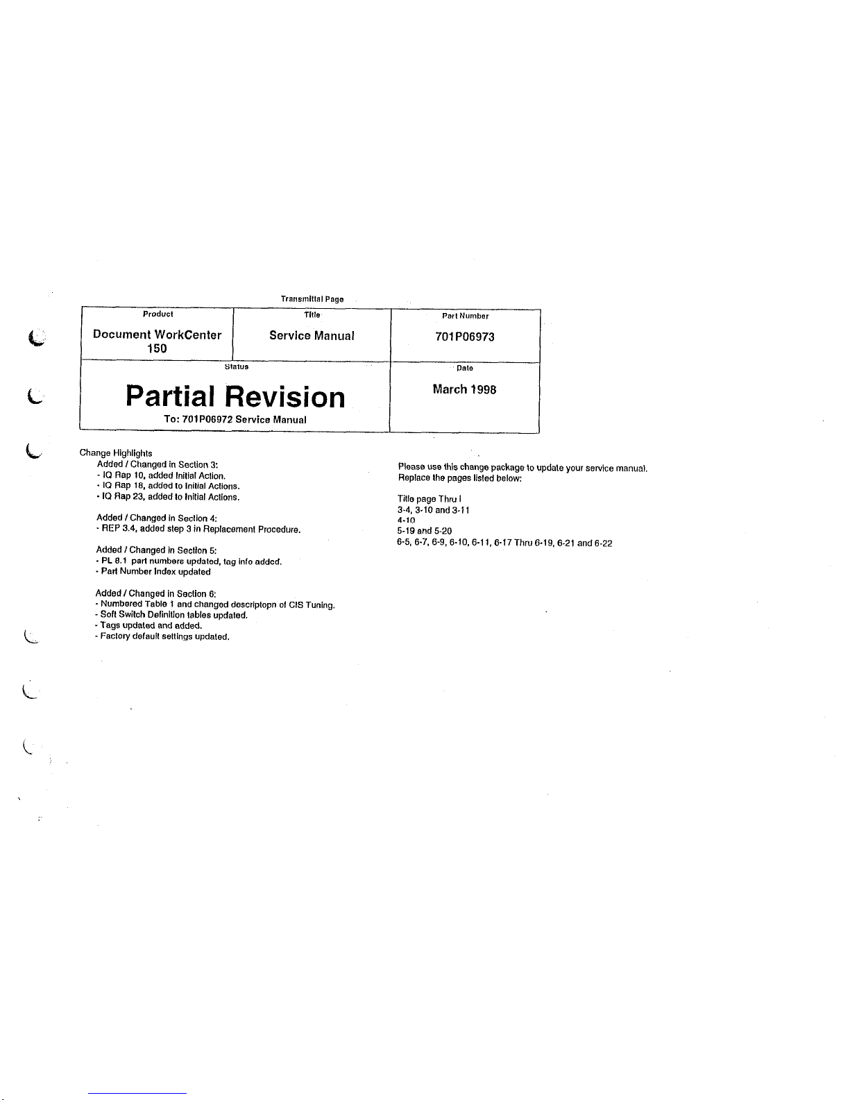
Transmlltal Page
Product Tim
Part Number
Document WorkCenter
Service Manual
701 PO6973
150
Slal”s
Ilate
/ Partial Revision I
March 1998
I
To:
701 PO6972 Service Manual
Change Highlighls
Added I Changed in Section 3:
- ICI Rap 10. added Initial Aclion.
. I(3 Rap 16. added lo Initial Aclions.
. IQ Rap 23, added lo lnilial Aclions.
Please use this change package to updale your service manual.
Replace Ihe pages listed below:
Tille ~aoe Thru I
3-4, i-ii and 3-i
1
4-10
Added I Changed in Seclion 4:
” REP 3.4, added slep 3 in Replacemenl
Procedure.
5-19 and 5-20
Added I Changed in Seclion 5:
. PL 6.1 part numbers updated. lag info added.
. Pad Number Index updaled
Added I Changed in Seclion 6:
. Numbered Table 1 and changed descriplopn of Cl.5 Tuning.
- So6 Swilch Definilion tables updaled.
_ Tags updaled and added.
- Faclory defaull sellings updeled.
6-5, 6-7. 6-9, 6-10,6-l 1, 6-17 Thru 6-19, 6-21 and 6-22
Page 2

Page 3
XEROX
Document WorkCenter 150
G Service Manual
CAUTION
The Main PWB has a lithium balfery which is
ml a spared item. /I fhe Main PWS fails,
relurn Ihs assembly to Ihe Xerox premises
for disposal in accordance wilh local
regulalions. DO NOT SHORT C/RCU/J
THEBATTERY
TERMINALS.
Page 4
NOTICE
All service documentation is supplied to Xerox
external cuslomers for inlormattonal purposes
only. Xerox service documentation is intended lot
use by certified. product Irained setvtc~ personnel
Only. Xerox does not warrant or represent that
such documentation is complete. Nor does Xerox
represent or warrant Ihst it will notify or provide lo
such cuslomer any tuture changes lo this
documentation. Service by the customer of
equipment, or modules. components, or parts of
such equipment may void any olhewise
applicable. Xerox warranties.
If Customer
Services such equipment, modules, components,
or parts thereof. Customer releases Xerox ham
any and all liability for aclions by the Customer,
and Customer agrees to indemnify. defend. and
hold Xerox harmless horn any third pady claims
which arise direclly or indirectly horn such
service.
Prepared by:
Xerox Corporallon
Customer 8 Service Documentation Development
PAHMl,
3400
Hlllvtew Avenue
Palo Alto. CA. 94304
0 1996 by Xerox Corporation. All rlghts F%BIVS~.
Xerox end all Xerox oroducls menlloned I” thts
publication 8~ reglslered trademarks 01 the Xerox
Corporalion.
Page 5
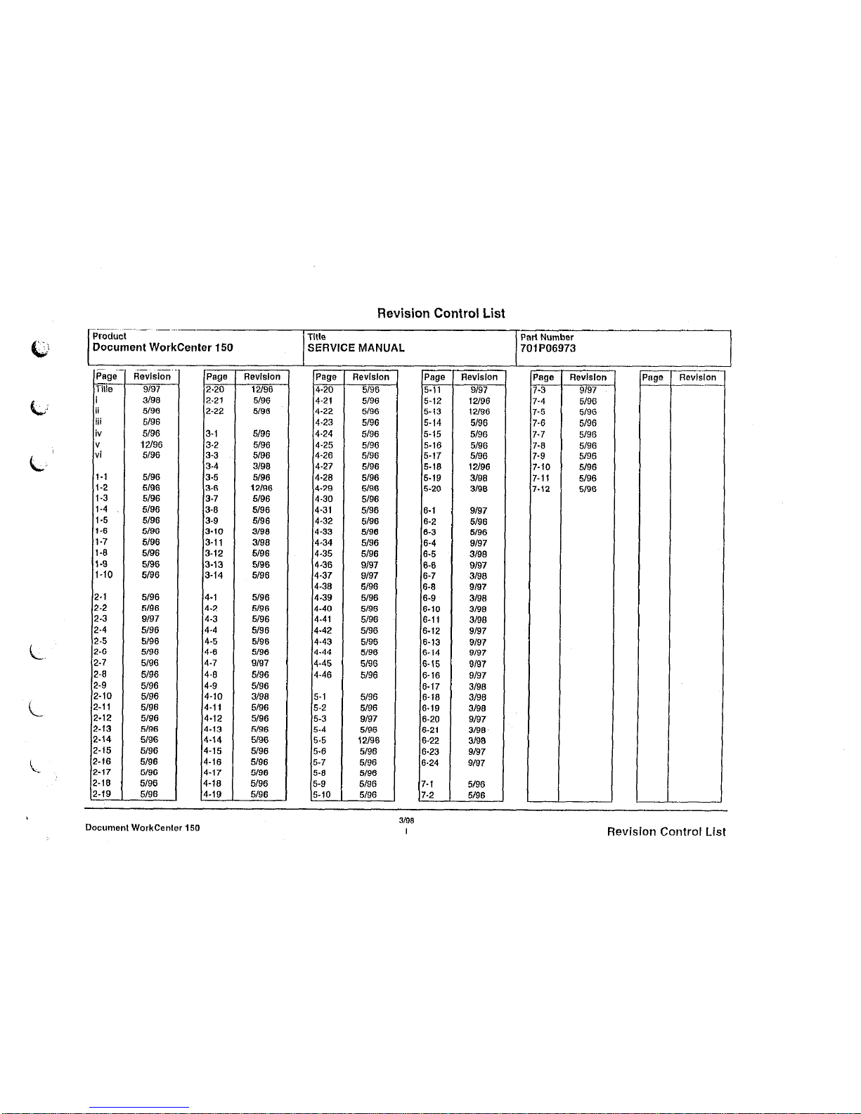
Revision Control List
Product
Title PartNumber
Document
WorkCenter 150 SERVICE MANUAL 701 PO6973
- -
Page
Tille
I
ii
iii
iv
"
vi
Aevlslon
9197
3198
5/96
5196
5/96
12l96
5/96
Page l7evlsion
2.20 12/36
2.21 5196
2-22
5/36
1-l
5196
l-2
5/36
i-3
5136
1-4 5136
1<5 5196
1-6 5196
i-7 5196
l-8 5196
I.3
5/36
l-10 5196
3-i 5136
3-2 5/96
3-3 5/96
3-4 3/98
3-5 5196
3-6
12l96
3-7
5196
3-6 5196
3-9 5136
3-10 3190
3-11 3198
3-12 5196
3-13 5136
3-14 5/96
2.1 5/96 4-l
5196
2.2 5196
4-2 5196
2.3
9197
4-3 5196
2-4
5196 4-4
5136
z-5 5/96 4-5 5/96
2.6
5196
4-6 5196
2-7 5496 4-7 s/97
2-6 5196 4-6
5196
2.9 5196 4-9 5196
2.10 5196 4-10 3198
2.11 5196 4-11 5196
z-12 5196
4-12 5196
2.13 5196
4-13 5/36
2.14 5/36 4.14 5136
z-15 5196 4-15 5196
2.16 5136 4-16 5196
2-17
5/96
4-17 5196
2.16 5196
4-16 5/96
2.19 5196 4-1s
5/36
Page Revision
4-20 5/96
4-21 5196
4-22 5/36
4-23 5196
4-24 5/96
4-25
5196
4-26
5196
4-27 5/96
4-26
5/96
4-2s 5/36
4-30 5196
4-31
5136
4.32
5196
4.33
5196
4-34 5136
4.35
5196
4-36 9/37
4.37
9197
4-36
5/96
4-3s
5136
4.40
5196
4.41
5196
4.42
5196
4-43 5/96
4.44
5196
4-45 5196
4.46
5196
5-l
5196
5-2
5196
5-3 9197
5-4
5196
5-5 12196
5-6
5196
5-7
5196
5-6
5196
5-9 5196
5.10
5196
Page Aevlslon
'age
Revision
5.11
9/97
-3
9/97
5.12 12/96 -4 5196
5-13 12/96
-5 5/96
5-14 5196
-6 5196
5-15 5196
-7
5196
5-16
5196
-6 5/96
5-17 5/96
-9 5196
5.16
12/96
-10 5136
5-19 3198
-11
5196
5-20
3138
-12
5/36
6-l
9197
6-2 5196
6-3 5196
6-4 3197
6.5 3198
6-6 9197
6-7
3198
6-6 s/97
6-9
3198
6.10 3136
6-11 3198
6-12 9137
6-13 s/97
6-14 9197
6-15 3137
6-16
9197
6-17 3198
6-16
3/98
6.19
3/98
6-20
9197
6-21 3198
6-22
3lS8
6-23
9137
6.24
9197
7-1 5/96
7-2 5196
-
DocumenlWorkCenler150
3/98
I
Revision Control List
Page 6
Page 7
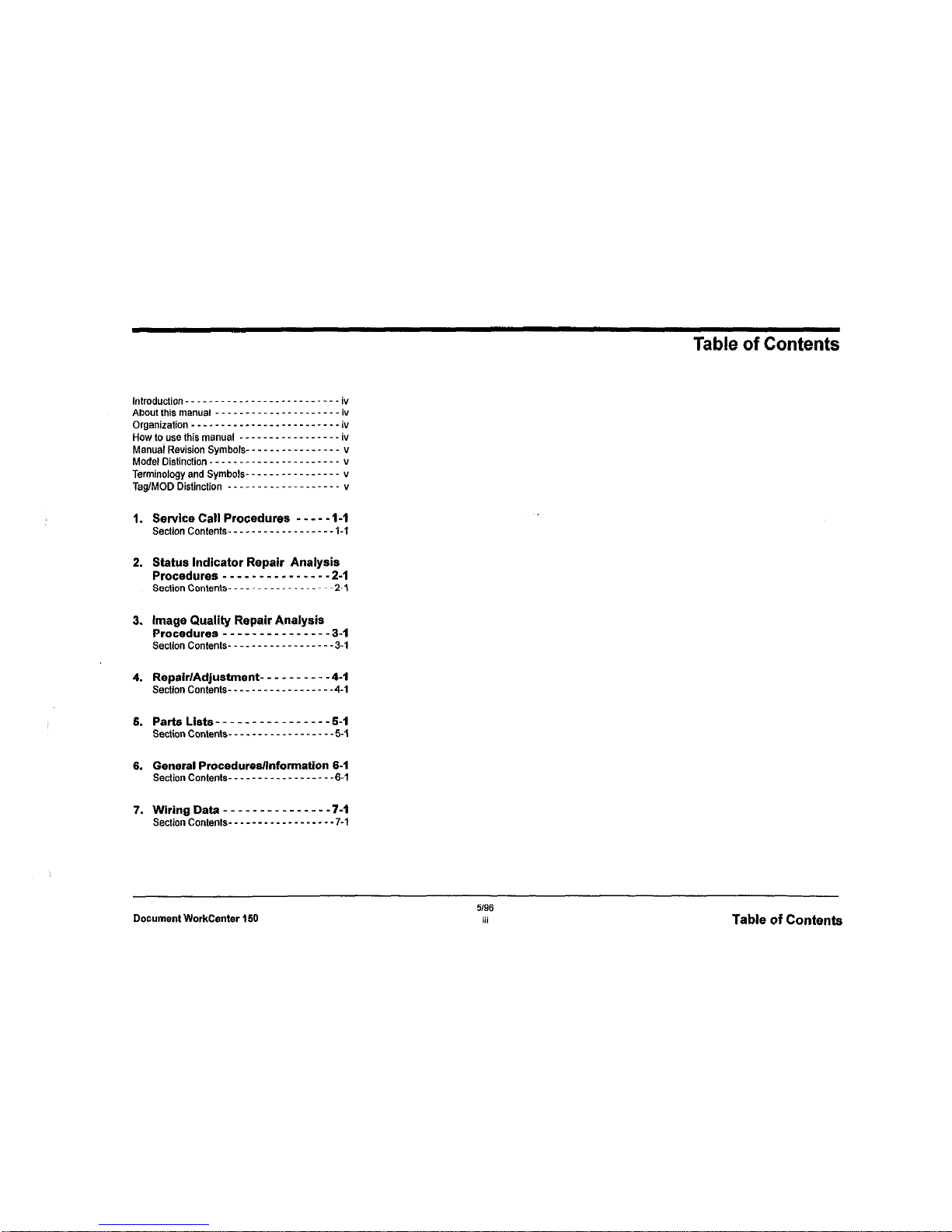
Table of Contents
3. Image Quality Repair Analysis
Procedures
-___---_ew----- 3-I
Section Co&n,s- _ _ _ - _ _ _ _ _ - _ _ _ _ - - -3-I
4. Repair/Adjustment- - - - - - - - - -4-I
Section Con,en,s- _ _ _ _ _ _ _ _ _ - _ _ _ _ - - -4.1
6. General Procedures/Information 6-1
Section Con,en,s- _ _ _ _ _ _ _ _ _ _ _ _ _ _ - _ -6.1
Document WorkCenter 150
5/w
iii
Table of Contents
Page 8
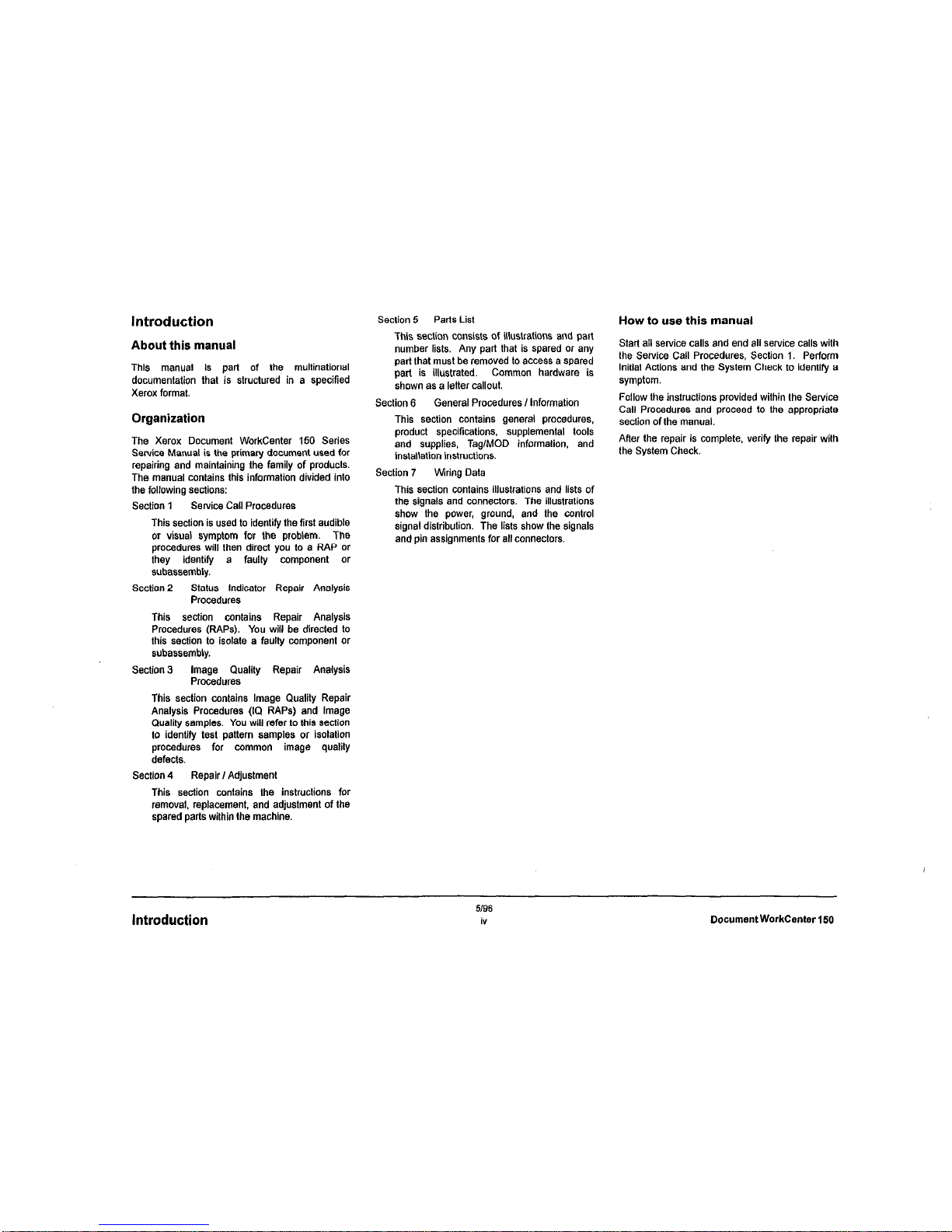
Introduction
About this manual
This manual is pan of the multinational
documentation that is structured in a specified
Xerox format.
Organization
The Xerox Document WorkCenter 150 Series
Service Manual is the primary document used for
repairing and maintaining the family of products.
The manual contains this information divided into
the following sections:
Section 1
Service Call Procedures
This section is used to identify the first audible
or visual symptom for the problem. The
procedures will then direct you to a RAP or
they identify a faulty component or
subassembly.
Section 2
Status Indicator Repair Analysis
Procedures
This section contains Repair Analysis
Procedures (RAPS). You will be directed to
this section to isolate a faulty component or
subassembly.
Section 3
Image Quality Repair Analysis
Procedures
This section contains Image Quality Repair
Analysis Procedures (t0 RAPS) and Image
Quality samples. You will refer to this sectlon
to identify test pattern samples or isolation
procedures for common image quality
defects.
Sectlon 4
Repair I Adjustment
This section contains the instructions for
removal, replacement, and adjustment of the
spared parts within the machine.
Section 5
Parts List
This section consists of illustrations and part
number lists. Any part that is spared or any
pert that must be removed to access a spared
part is illustrated. Common hardware is
shown as a letter callout.
Section 6
General Procedures I tnformation
This section contains general procedures,
product specifications, supplemental tools
and supplies, Tag/MOD informalion. and
installation instructions.
Section 7 Wiring Data
This section contains illustrations and lists of
the signals and connectors. The illustrations
show the power, ground, and the control
signal distribution. The lists show the signals
and pin assignments for all connectors.
How to use this manual
Start all service calls and end all service calls with
the Service Call Procedures, Section 1. Perform
Initial Actions and the System Check to identify a
symptom.
Follow the instructions provided within the Service
Call Procedures and proceed to the appropriate
section of the manual.
After the repair is complete, verify the repair with
the System Check.
Introduction
5/96
iv
DocumentWorkCenter 150
Page 9
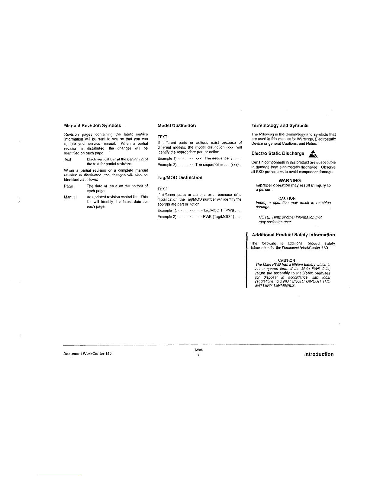
Manual Revision Symbols Model Distinction
Revision pages containing the latest service
information~ will be sent to you so that you can
update your service manual. When a partial
revision is distributed, the changes will be
identified on each page.
TEXT
Text
Black vedical bar al the beginning of
the text for partial revisions.
If different paris or actions exist because of
different models, the model distinction (xxx) will
identify the appropriate part or action.
Example 1). - - - xxx: The sequence is.
Example 2) - - - The sequence is. (xxx).
When a partial revision or a complete manual
revision is distributed, the changes will also be
identified as follows:
Tag/MOD Distinction
Page
ManLLFll
The date of issue on the bottom of
each page.
An updated revision control list. This
list will identify the latest date for
each page.
TEXT
If different parts or actions exist because of a
modification, the Tag/MOD number will identify the
appropriate part or action.
Examplel).-----------Tag/MODl: PWB...
Example2) -----------PWBCTag/MODl)...
Terminology and Symbols
The following is the terminology and symbols that
are used in this manual for Warnings, Electrostatic
Device or general Cautions, and Notes.
Electra Static Discharge k,
Certain components in this product are susceptible
to damage from electrostatic discharge. Observe
all ESD procedures lo avoid component damage.
WARNING
Improper operation may result in injury to
a person.
CAUTtON
lmpmper operation may result in machine
damage.
NOTE: Hinfs orofher information that
may assist the LL%V
Additional Product Safety information
The following is additional product safely
, information for the Document WorkCenter 150.
I
CAUTION
The Main P WE has a lithium baffery which is
not a spared item. If the Main PWB fails,
relum the assembly to the Xerox premises
for disposal in accordance wilh local
regulations. DO NOT SHORT CIRCUIT THE
BATTERY TERMINALS.
Document WorkCenter 150
12/96
Y
Introduction
Page 10
5196
Introduction
vi
Document WorkCenter 150
Page 11
1 Service Call Procedures
Introduction
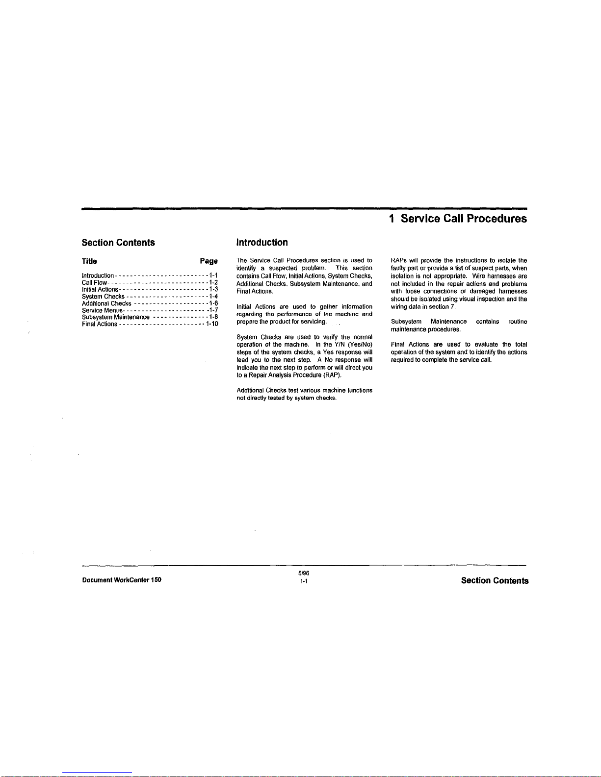
The Service Call Procedures section is used to
identify a suspected problem.
This section
contains Call Flow, tnitial Actions, System Checks,
Additional Checks, Subsystem Maintenance. and
Final Actions.
Initial Actions are used to gather information
regarding the performance of the machine and
prepare the product for servicing.
System Checks are used to verify the normal
operation of the machine. In the Y/N (Yes/No)
steps of the system checks, a Yes response will
lead you lo the next step. A No response will
indicate the next step to perform or will direct you
to a Repair Analysis Procedure (RAP).
Additional Checks test various machine functions
not directly tested by system checks.
RAPS will provide the instructions to isolate the
faulty part or provide a list of suspect parts, when
isolation is not appropriate. Wire harnesses are
not included in the repair actions and problems
with loose connections or damaged harnesses
should be isolated using visual inspection and the
wiring data in section 7.
Subsystem
Maintenance contains
routine
maintenance procedures.
Final Actions are used to evaluate the total
operation of the system and to identify the actions
required to complete the service call.
Document WorkCenter 150
5196
1-i
Section Contents
Page 12
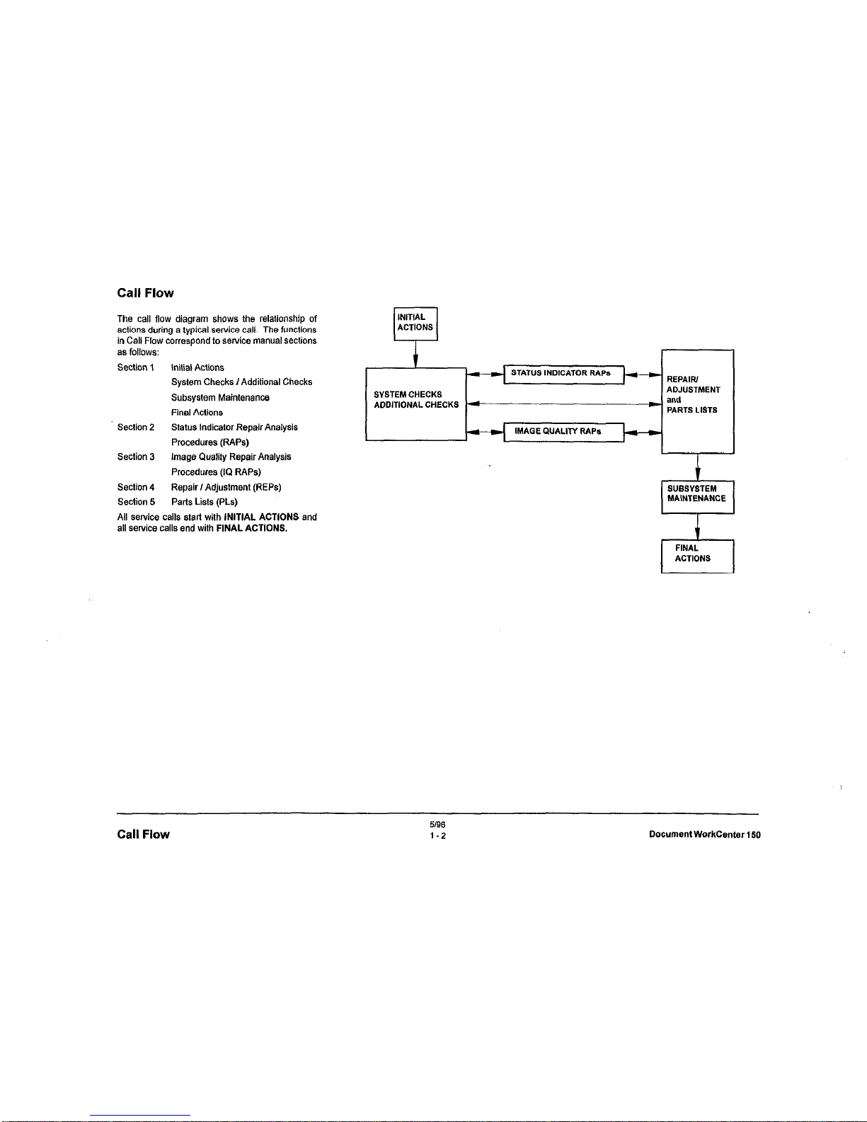
Call Flow
The call flow diagram shows the relationship of
actions during a typical service call. The functions
in Call Flow correspond to service manual sections
as follows:
Section 1
Initial Actions
System Checks I Additional Checks
Subsystem Maintenance
Final Actions
Section 2
Status Indicator Repair Analysis
Procedures (RAPS)
Section 3 Image Quality Repair Analysis
Procedures (IQ RAPS)
Section 4
Repair I Adjustment (REPS)
Section 5
Parts Lists (PLs)
All SeNica calls stall with INITIAL ACTIONS and
all service calls end with FINAL ACTIONS.
INITIAL
n
ACTIONS
MAGE QUALITY RAPS
Call Flow
5196
1-2
Document WorkCenter 150
Page 13
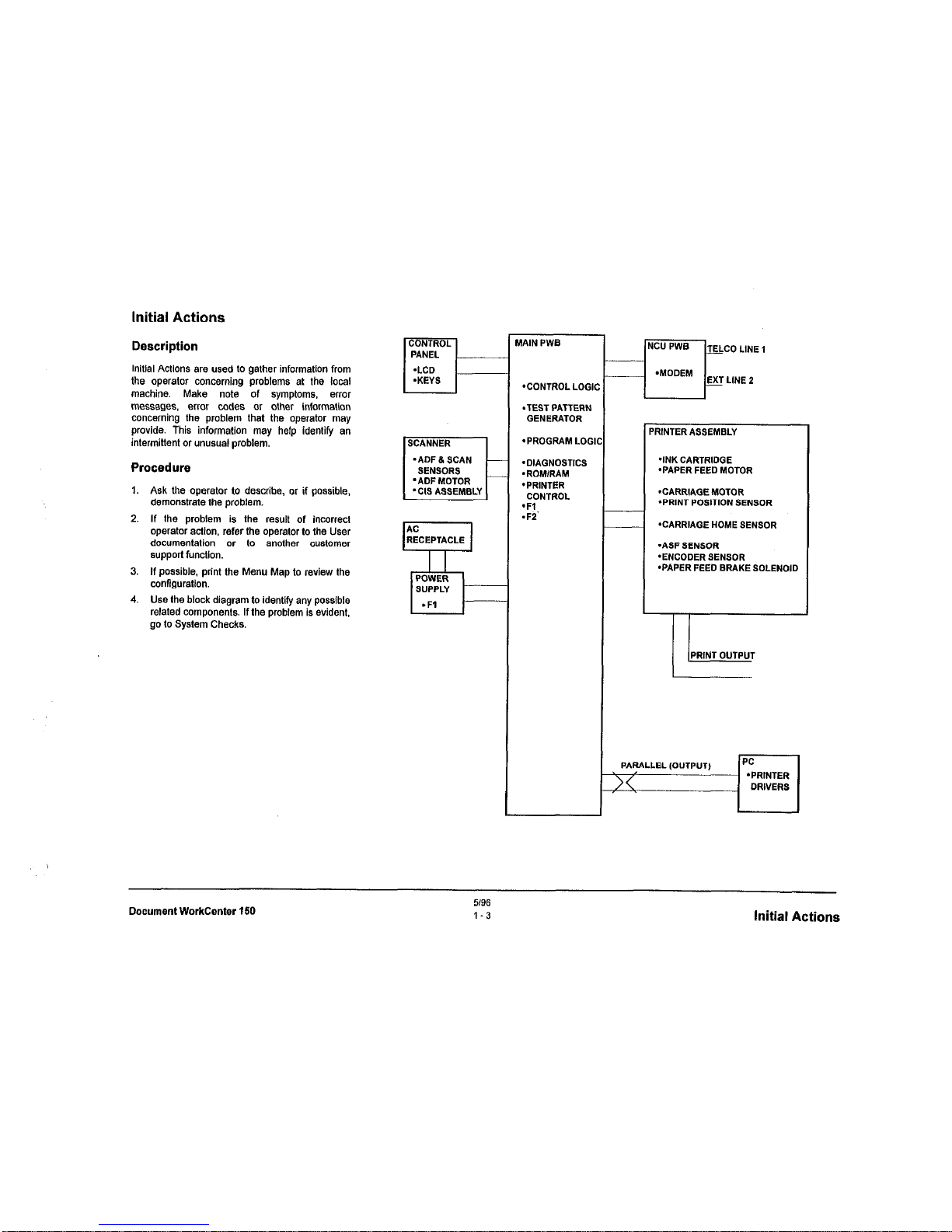
Initial Actions
Description
initial Actions are used to gather information from
the operator concerning problems at the local
machine. Make note of symptoms, emx
messages, ertcr codes or other information
concerning the problem that the operator may
provide. This information may help identify en
intermittent or unusual problem.
Procedure
1.
Ask the operator to describe, or if possible,
demonstrate the problem.
2. If the problem is the result of incorrect
operator action. refer the operator to the User
documentation or to another customer
support fu”ctl0”.
3.
If possible, print the Menu Map to review the
wnftguration.
4.
Use the block diagram to identify any possible
related components. If the problem is evident,
go to System Checks.
’ ADF 8 SCAN
SENSORS
’ ADF MDTOR
‘CIS ASSEMBLY
HAIN PWB
*CONTROL LOGIC
.TEST PATTERN
GENERATOR
*PROGRAM LOGII
‘DIAGNOSTICS
.ROMlRAM
*PRINTER
CONTROL
‘Fl
.Fi
‘RINTERASSEMBLY
*INK CARTRIDGE
‘PAPER FEED MOTOR
‘CARRIAGE MOTOR
*PRINTPOSlTlONSENSOR
‘CARRIAGE HOME SENSOR
‘ASF SENSOR
-ENCODERSENSOR
‘PAPER FEED BRAKE SOLENOID
I-
PRINT OUTPUT
Document WorkCenter 150
5/96
1-3
Initial
Actions
Page 14
System Checks
Initial conditions
Inspect for the following conditions:
.
Ensure the telephone is connected properly.
.
Ensure that the telephone line cable is
connected correctly at the machine line jack
and the wall jack.
-
Ensure that the power cord is connected lo
the wall outlet and to the machine.
*
No documents are loaded and scanner is
free
of foreign particles.
-
The scanner is correctly closed.
*
The paper is loaded correctly in the printer.
*
Ensure the parallel cable is not connected.
Off-Line System Checks
NOTE:
If an ERROR MESSAGE
appears at any time, do
Refer to section 2, &b/e 1 disg&
LuQSiWLor tahb 2
elmr -and
NOTE: The displays shown in the
system checks may vary fmm those on
the machine being tested in /he
following areas:
.
Time
.
Local ID
* Telephone numbers
*
Original and resolution selections
.
CCITT operation modes (9600, ECM)
Differences in the above items should not be
interpreted as a problem.
1.
2.
3.
4.
5
6
7
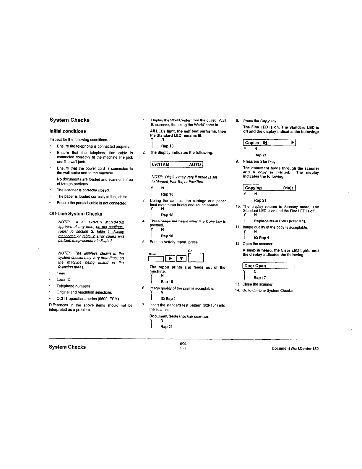
Unplug the WorkCenter from the outlet. Wait
10 seconds, then plug the WorkCenter in.
All LEDs light, the self test performs, then
the Standard LED remains lit.
i kpl0
The display indicates the following:
1 09:llAM
AUTO 1
NOTE:
Display may vary if mode is set
to Manual, Fax Tel, or FwTam.
i LPI3
During the self test the carriage and paper
feed motors run brietly and sound normal.
Y N
I
Rap 18
Three beeps are heard when the
Copy
key is
pressed.
i :ap+s
Print an Activity report, press
The report prints and feeds out of the
machine.
i ~ap16
image quality of the print is acceptable.
i fbRap1
Insert the standard test pattern (82P151) into
the scanner.
Document feeds into the scanner.
i lap21
6.
9.
10
11
12
13.
14.
Press the Copy key.
The Fine LED is on, The Standard LED is
off and the display indicates the following:
1 Copies : 01
i :a,21
b]
Press the Start key.
The document feeds through the *canner
and a copy is printed.
indicates the following:
The display
Copying
i LIP21
Ol/Ol )
The display returns to Standby mode, The
Standard LED is on and the Fine LED is off.
i
:.place Main PWB (REP 8.1).
tmage quality of the copy is acceptable.
i !lRsp,
Open the scanner.
A beep is heard, the Error LED lights and
the display indicates the following:
Door Open
i zap17
Close the scanner.
Go to On-Line System Checks,
System Checks
5/96
1-4
Document WorkCenter 150
Page 15

On-Line System Checks
NOTE: Perfom, these checks only
afler the Off-Line System Checks have
been performed.
1.
2.
3.
4.
5.
.
.
Insert a document in the scanner
Use the keypad on the control panel to dial a
nearby telephone number, press Start.
The WorkCenter dials the telephone number
and
the display
indicates
the
following.
I
Dialing
J
i NRap24
Ringing is heard from the remote telephone.
i Lql26
Press Stop when ringing is heard
NOTE: For fhe next step ensure lhe
WorkCenter is set to “Auto Receive”
answer on the first ring. (Refer to
Chapters 4 & 9 in the Users Guide).
Oial the WorkCenter from a remote telephone.
Ringing Is heard and the display indicates
the following after 1 ring.
1 CONNECTING
I
i :C” PWB (REP8.3)
For Fax problems, perform RAP 26.
For PC printing problems, verify the correct
printer driver is installed in the PC and a
parallel cable is connected. If OK, replace the
Main PWB (REP&l).
For all other problems, go to Additional
Checks on the next page.
996
I-5
System Checks
Page 16
Additional Checks
Description
This section is used to identify specific problems
which did not occur during system checks. Many
times the decision will have to be based on the
customers explanation of the problem.
Always complete the Off-Line and On-Line system
checks before using these procedures.
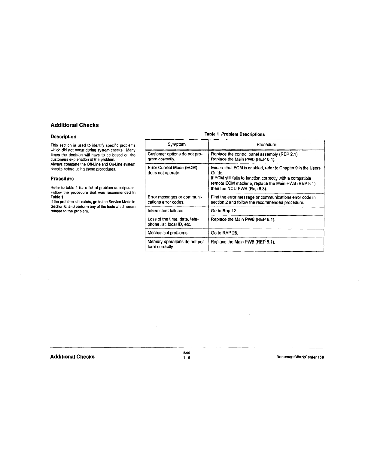
Refer to table 1 for a list of problem descriptions.
Follow the procedure that we8 recommended in
Table I.
If the problem stilt exists, go to the Service Mode in
Section 6. and perform any of the tests which seem
related to the problem.
Table 1 Problem Descriptions
Symptom Procedure
Customer options do not pro-
Replace the control panel assembly (REP 2.1).
gram correctly.
Replace the Main PWB (REP 8.1).
Error Correct Mode (ECM)
does not operate.
Ensure that ECM is enabled, refer to Chapter 9 in the Users
Guide.
If
ECM
still fails to function correctly with a compatible
remote ECM machine, replace the Main PWB (REP 8.1)
then the NCU PWB (Rep 8.3).
Error messages or communi-
I
Find the error message or communications error code in
cations error codes.
section 2 and follow the recommended procedure.
I
Intermittent failures
1 Go to Rap 12.
Loss of the time, date, tele-
Replace the Main PWB (REP 8.1).
phone list, local ID, etc.
I
Mechanical problems
Go to RAP 28.
Memory operations do not per- Replace the Main PWB (REP 8.1).
form correctly.
Additional Checks
5/96
I-6
Document WorkCenter
Page 17
The Service Mode provides additional service tests
for diagnosis of problems.
The complete
procedure for the Service Mode tests can be found
in section 6.
Refer to section 5 for adjustment procedures or
section 6 for the d&ailed descriptions and
procedures for these tests.
Procedure
The service mode is cancellad automatically after
approximately 3 minutes of no machine activity.
1,
Enter Service Mode, Press:
sisli
The display indicates
the
following.
1 SeRVlCE (1-s) x.x1
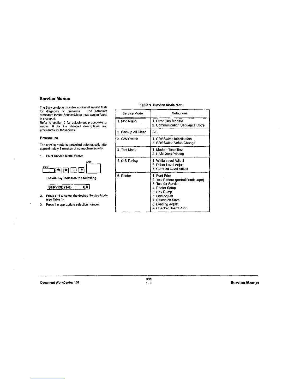
2.
Press I- 6 10 select the desired Service Mode
(see Table I).
3.
Press the appropriate selection number.
Table 1 Service Mode Menu
Selections
I. Error Line Monitor
2. Communication Sequence Code
ALL
1. S.W Switch Initialization
2. SIW Switch Value Change
1. Modem Tone Test
2. RAM Data Printing
1. White ievel Adjust
2. Dither Level Adjust
3. Contrast Level Adjust
1. Font Print
2. Test Pattern (portrait/landscape)
3. Test for Service
4. Printer Setup
5. Hex Dump
6. Grid Adjust
7. Select Ink Save
13. Loading Adjust
9. Checker Board Print
Document WorkCenter 150
5196
1-7
Service Menus
Page 18
Subsystem Maintenance
Detailed procedure
Description
This section contains a check list and a detailed
procedure for subsystem maintenance. The parts
should be inspected and cleaned as required. The
printer should be cleaned and lubricated if
accessed for the repair of a problem.
1. Disconnect the power cord.
2. Open the Front Cover.
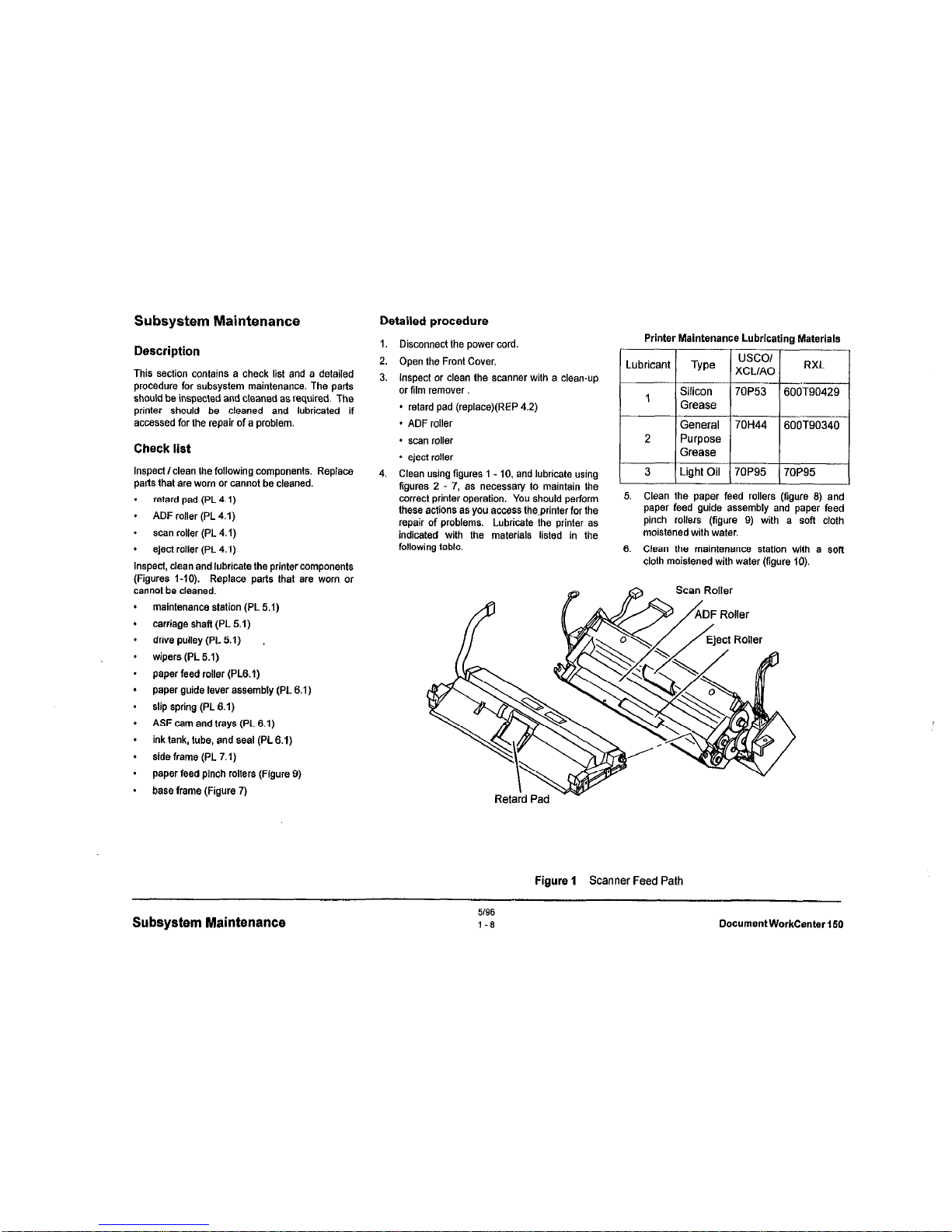
3. Inspect or clean the scanner with a clean-up
or film remO”er
* retard pad (replace)(REP 4.2)
. ADF roller
Check list
* scan roller
Inspect/clean the following components. Replace
parts that are worn or cannot be cleaned.
. retard pad (PL 4.1)
.
ADF roller (PL 4.1)
* scan roller (PL 4.1)
- eject roller (PL 4.1)
Inspect. clean and lubricate the printer components
(Figures I-10). Replace parts that are worn or
cannot be cleaned.
* eject roller
4. Clean using figures 1 - 10. and lubricate using
figures 2 - 7, as necessary to maintain the
correct printer operation. You should perform
these actions as you access the.printer for the
repair of problems. Lubricate the printer as
indicated with the materials listed in the
following table.
maintenance station (PL 5.1)
carriage shaft (PL 5.1)
drive pulley (PL 5.1)
wipers (PL 5.1)
paper feed rolter (PL6.1)
paper guide lever assembly (PL 6.1)
slip spring (PL 6.1)
ASF cam and trays (PL 6.1)
ink tank, tube, and seat (PL6.1)
side frame (PL 7.1)
paper feed pinch rollers (Figure 0)
base frame (Figure 7)
Printer Maintenance Lubricating Materials
Lubricant
TYPO
usco/
XCLIAO
RXL
I
I
I
3 1 Light Oil I7OP95 ( 7OP95
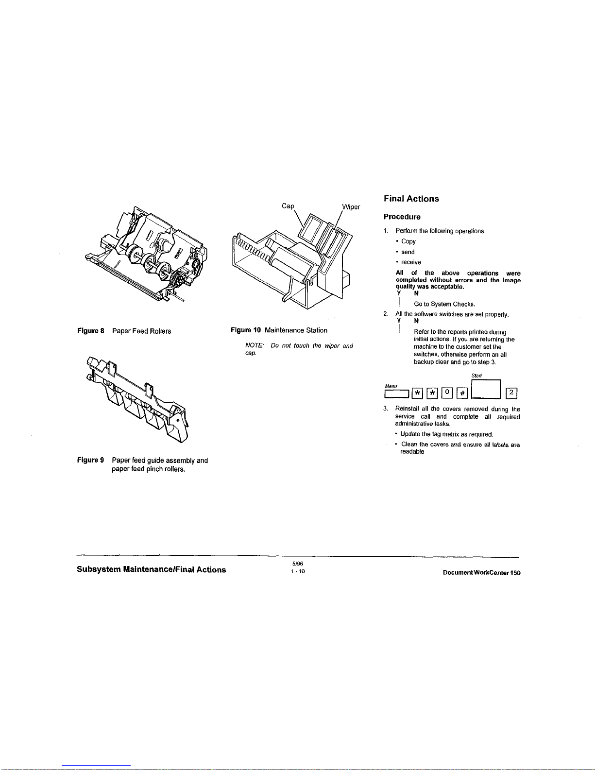
5. Clean the paper feed rollers (figure 8) and
paper feed guide assembly and paper feed
pinch rollers (figure 0) with a soft cloth
moistened with water.
8. Clean the maintenance station with a sofl
cloth moistened with water (figure 10).
Scan Roller
Figure 1 Scanner Feed Path
Subsystem Maintenance
5/96
l-8
DocumentWorkCenter150
Page 19
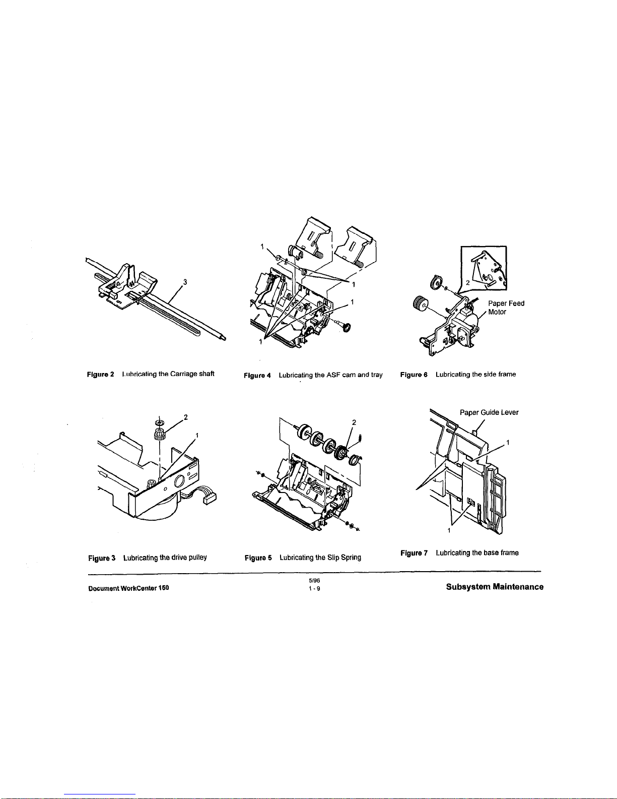
Flgure 2
Lubricating the Carriage shaft
Figure 3
Lubricating the drive pulley
Figure 5
Lubricating the Slip Spring
Figure 4
Lubricating the ASF cam and tray Figure 6
Lubricating the side frame
Figure 7
Lubricating the base frame
Document WorkCenter 150
5196
1-S
Subsystem Maintenance
Page 20
Final Actions
Procedure
1.
Perform the following operations:
* COPY
* send
* receive
All of the above operations were
completed
without errcm
and the image
quality
was acceptable.
i :CI lo System Checks.
2. All the software swilches are set properly.
Figure 8
Paper
Feed Rollers
Figure
IO Maintenance Station
i N
Refer to the reports printed during
NOTE: Do nof touch the wiper and
initial actions. If you are returning the
machine to the cuslomer set the
Cap.
switches, othenvise perform an all
backup clear and go to step 3.
3. Reinstall all Ihe cwers removed during the
SeNice
call and complete all required
administrative tasks.
* Update the tag matrix as required.
- Clean the cwers and ens”re all labels are
readable
Figure 9
Paper feed guide assembly and
paper feed pinch rollers.
Subsystem Maintenance/Final Actions
DocumentWorkCenter150
Page 21
2 Status Indicator Repair Analysis Procedures
Section Contents
Introduction
Title
Page
Intro&&n _.___._______ __ __________ 2-1
M*asu,*m*“ts .__----____- ___ ___- ----*-,
D,sp,ayM*ss*g*s ------ _ _--- ____ .---- 2.2
Communication Error Codes- - - - - - - - _ - - - -2-3
RAP10 InputPower------------------Z-4
RAP 12 Intermittent Failures - - - - - - - - - - - -2-6
RAP 13 Blank or Garbled Display
- - - - - - _ -2-7
RAP15 ControlPanelLEDs ------------Z-E
RAP 16 Control Panel Keys _ - - - - - _ _ -----Z-Q
RAP 17 Scanner Interlock - - - _ _ - - - - - _ _ -2-10
RAP18 PaperFeeding---------------Z-11
RAP20 InkCartridge ----------------Z-l4
RAP 21
Document Feeding - _ - - - - - - - - - - 2-16
RAP 23 Printer Comm Error- - - - _ - - - - - - - 2-18
RAP24
DialTo,,, .-____ _ ____ __ _____ -2-18
RAP 25 Dialing and Connecting - - - - - - _ - -2-19
RAP 26 Transmit and Receive Errors - - - - -2-20
RAP 27 Paper Feed Brake Solenoid- - - - -2-21
RAP 28 Mechanical Checkout - - - - - - - - - _ 2.22
The Repair Analysis Procedures section is used
to isolate and identify problems to a faulty
component or subassembly. It contains the
Introduction, display message
table,
communication errw code table and the Repair
Analysis Procedures (RAPS).
The various tables include all operator messages
indicated in the display and their meanings. The
tables will also list the Transmit z&Receive error
codes and associated messages.
Use the Display Messages and Communication
Error Codes tables when messages are displayed
or error codes are printed in a report.
The Repair Analysis Procedures (RAPS) are
accessed from Section I, system checks or
additional checks. There are two types of RAPS:
Status Indicator (Sl) RAPS. contained in this
section, and Image Quality (IQ) RAPS, located in
Section 3.
RAPS will normally isolate a problem to a specific
component or subassembly, excluding the wire
harnesses.
In the Y/N (Yes/No) steps of the RAPS, a Yes
response will lead you to the next step. A No
response will indicate a corrective action. When
the indicated corrective action has been
completed, go to Section 1 and restart the System
Check to verify that the problem has bean
corrected.
Measurements
Power and signal grounds are connected to frame
ground, therefore all circuit troubleshooting can
be performed using the metal frame (chassis) as
the QrOundinQ point. lf more information is
needed to locate connectors or test points, refer
to section 7.
NOTE: Make all voltage to ground
unless instmcted to measum fmm “xx”
to “xx
Unless otherwise specified , the following voltage
lolerances are used within this section:
St&d------u- _____ _.__ ___“.__ ,&as”&
+5OVDC---------+4.75VDCto+5.25VDC
+12.0 VDC - - _ - - - - -+ 10.8 VDC to + 13.2 VDC
-12.0 VDC - - - - - - - -10.8 VDC to -13.2 VDC
+ 42.3 VDC - - - - - - - - -+37.8 VDC to +41X2 VDC
,,,,,,,,-,C _____ _____ ____ _ ____ __ +0,5,,,,C
Document WorkCenter 150
396
2-l
Section Contents
Page 22
Display Messages and Communication error codes
If a” error code is available, refer lo Table 2.
If no error code, refer to Table 1 for the message and the procedure.
not listed, return to section 1, additional checks.
If no error code is available and the message is
Display messages
ADD PAPER
Check Printer...
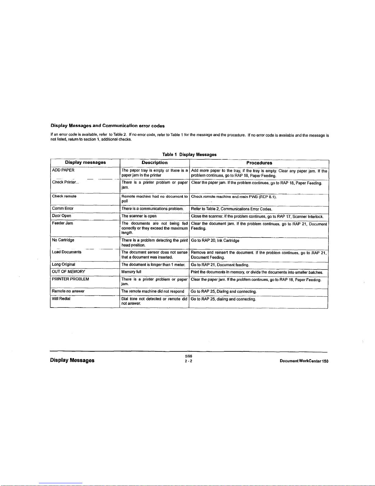
Table 1 Display Messages
Description
Procedures
The paper tray is empty or there is a
paperjam in the printer
Add more paper to the tray, if the tray is empty. Clear any paper jam. If the
problem continues, go to RAP 18, Paper Feeding.
There is a printer problem or paper Clear the paper jar”. If the problem continues, go to RAP 18, Paper Feeding.
jam.
Check remote
Comm Error
Door Open
Feeder Jam
Remote machine had no document to Check remote machine and main PWB (REP 8.1).
poll
There is a communications problem. Refer to Table 2, Communications Error Codes.
The scanner is open
Close the scannar. If the problem continues, go to RAP 17, Scanner Interlock.
The documents a&z not being fed Clear the document jam. If the problem continues. go to RAP 21, Document
correctly or they exceed the maximum
Feeding.
No Cartridge
Load Documents
Long Original
OUT OF MEMORY
PRtNTER PROBLEM
Remote no answer
will Redial
length.
There is a problem detecting the print
Go to RAP 20, Ink Carlridge
head position.
The document ssnsor does not sense
Remove and reinsert the document. If the problem continues, go to RAP 21,
that a document was inserted. Document Feeding.
The document is longer than 1 meter.
Go to RAP 21. Document feeding.
Memory full
Print the documents in memory, or divide the documents into smaller batches.
There is a printer problem or paper Clear the paper jam. If the problem continues, go to RAP 18, Paper Feeding.
jam.
The remote machine did not respond Go to RAP 25, Dialing and connecting.
Dial lone not detected or remote did Go to RAP 25, dialing and connecting.
not answer.
Display Messages
5/96
2-2
Document WorkCenter 150
Page 23
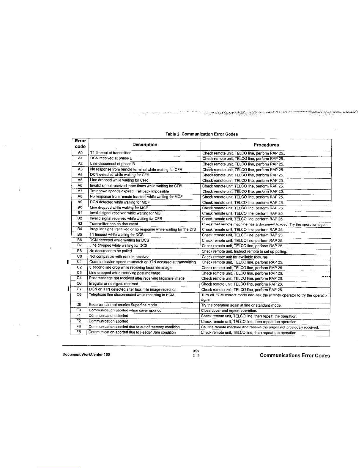
Table 2 Communication Error Codes
trror
code
Description
A0
T1 timen,,, irt tr3ncmiH~r
. ..__I. I. ..I..“......“.
Pkeck remote unit. TELLX
Al
_^.. UC;N recewe* at pnase El
Chew I~IIIUVZ urw, I CL~\
A2
Line disconnart 11 nhzxe R
rheck remote unit. TELCX
Procedures
“II
1 line, perform RAP 25..
_A_ _^__._ .._:I I,--, n
‘I line. perform RAP 25..
“II
1 line, perform RAP 25.
! ^_I, _^_^I^ .._:. IT--, nq line, perform RAP 25,
1 line. perform RAP 25.
A3
1 NO response from remote terminal while waitino for cFR
I
oacn lmposslale
mit, TELCO line, perform RAP 25.
--. ,.
‘I line. perform RAP 25.
, ,,,3 line, perform RAP 25.
_-I_ _^__‘_ ..-:- 7-s “9 ,i”e, perform RAP 25,
1 line, perform RAP 25.
^-lr ----‘- ‘mit,
TELCO line, perform RAP 25.
line, perform
RAP 25.
I
0 wnw wamng
,or C-K
,,,,3 line, perform RAP 25.
e has a document loaded. Try the operation again.
1 line, perform RAP 25.
nit, TELCO line. perform RAP 25.
--’ “7 line, perform RAP 25.
-- . _ ..-..... J
) line. perform RAP 25.
_- ^.^..
nit.
Instruct remote to set up polling.
lable features.
,,,3 line, perform RAP 25.
__I_ _^__._ ..-:.
Post message not received after receiving facsimile image
Irregular or no signal received
DCN or RTN detected after facsimile image ran-n+;-Telephone line disconnecled while receiving in ECM.
Irl “P) ,ine, perform RAP 26,
‘hsck remote unit. TELCC -,,~
I line. perform RAP 26.
Chtw. ,r,,,u,r u,
-. .^LI -^-^ ,^
nit, TELCO line. perform RAP 26.
Check remote un~r. I CLU
~” --’ “7 line, perform RAP 26.
’ Ch%k remote unit. TELCC
I ““5
) line, perform RAP 26.
1 Turn off ECM correct mode
! and ask the remote operator to try the operation
again.
I
D9
Receiver can not receive Superfine mode.
1 Tw the ope.-‘;-~-
FO
com()l,mi.-2tin” d,nrbrl Wh‘,” r,Ts,er nn.3nmi
’ P’-se cove
Fl
F2
F3
F5
c4
C6
c7
C6
Document WorkCenter $50
9/97
2-3
Communications Error Codes
Page 24
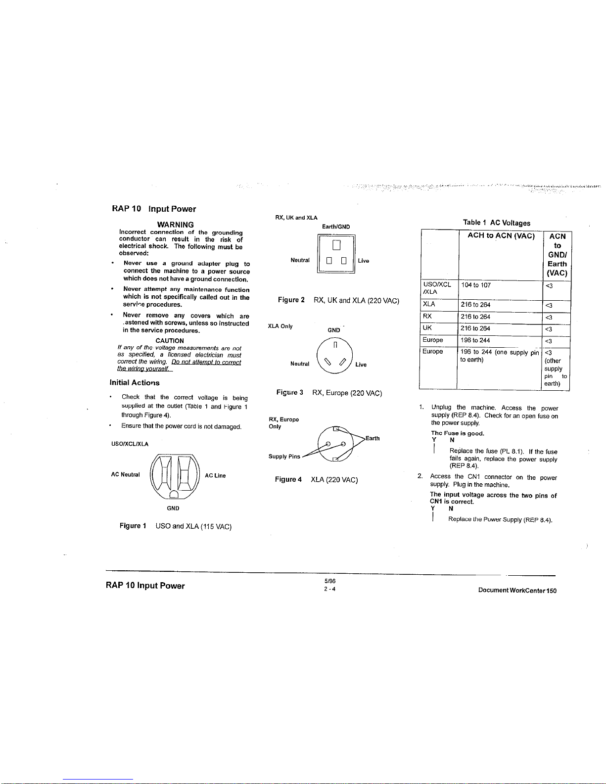
RAP 10 Input Power
WARNING
Incorrect
connection of the grounding
conductor can result in the risk of
electrical shock. The following must be
observed:
.
Never “se a ground adapter plug to
connect the machine to a power source
which does not have a ground connection.
.
Never attempt any maintenance function
which is not specifically called out in the
service procedures.
.
Never remove any covers which are
.astened with screws, unless so instructed
in the service procedures.
CAUTION
If any of the voltage measurements are not
as specified, a licensed electrician most
Initial Actions
* Check that the corred voltage is being
supplied at the outlet (Table 1 and Figure 1
lhrough Figure 4).
* Ensure that the power cord is not damaged.
usolxcuxlA
AC Neutral
AC Line
Figure 1 US0
and XLA (115 VAC)
RX, UK and XLA
EarthlGND
Neutral
Live
Figure 2
RX, UK and XLA (220 VAC)
XLA Only
GND
Neutral
Figure 3
RX, Europe (220 VAC)
RX. Eurom
Only
Earth
Supply Pins
Figure 4 XLA (220 VAC)
Table 1 AC Voltages
ACH to ACN (VAC)
USO/xCL
104 to 107
MLA
XLA
216 to 264
RX
216 to 264
UK
216to264
Europe
196to244
ACN
to
GNDI
Earth
WC)
E3
c3
c3
:3
:3
:3
other
;“PPlY
>I” to
!arth)
1. Unplug the machine. Access the power
supply (REP 8.4). Check for an open fuse on
the power supply.
The
Fuse is good.
i No
Replace the fuse (PL 8.1). If the fuse
fails again. replace the power supply
(REP 6.4).
2. Access the CNI connedor on the power
supply. Plug in the machine.
The input voltage across the two pins of
CNl is correct.
i N
Replace the Power Supply (REP 6.4).
RAP
10
Input Power
51%
2-4
DocumentWorkCenter150
Page 25
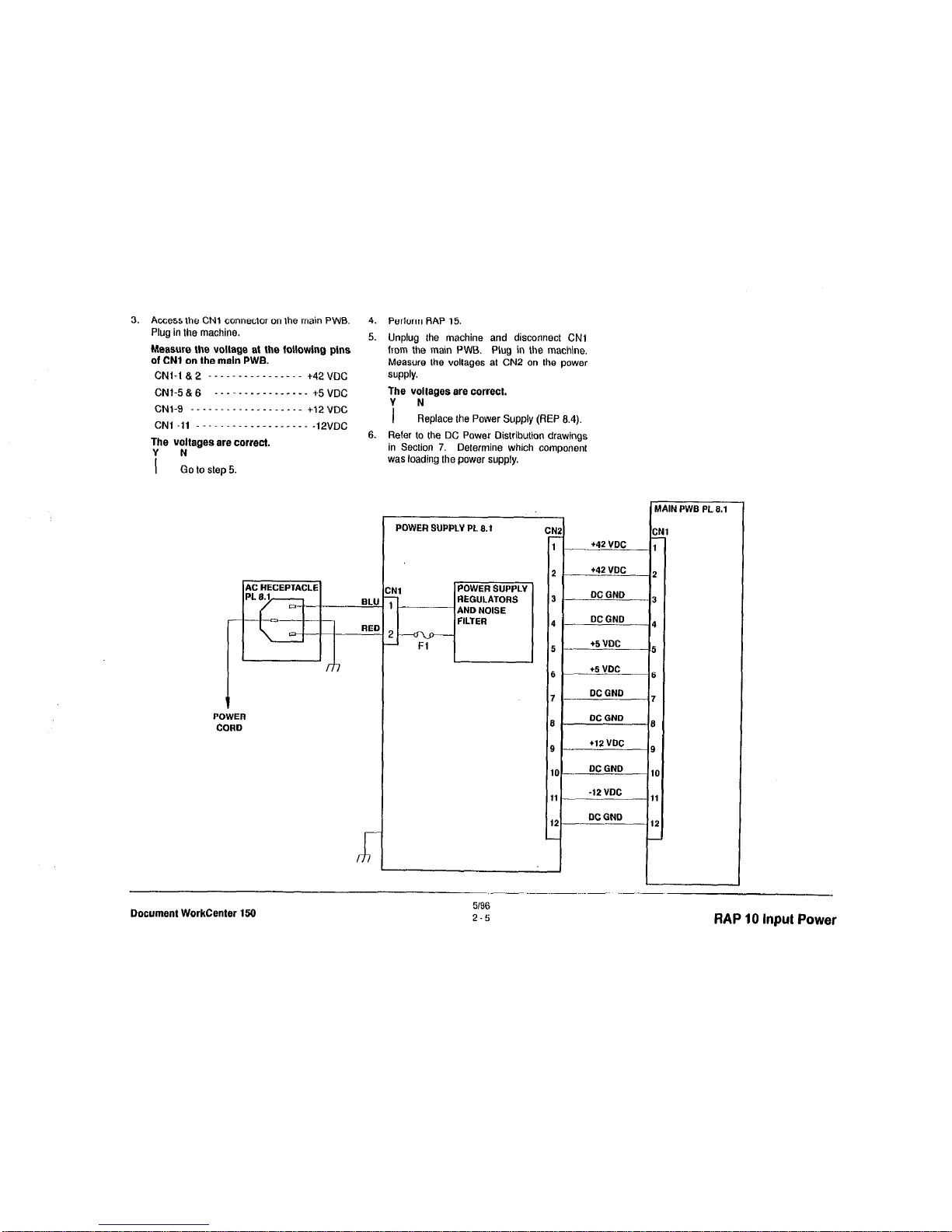
3.
Access lhe
CNl connector on the main
PWB.
Plug in the machine.
The voltages ere correct.
Y N
1 Go to step 5.
POWER
CORD
4.
Perform RAP 15.
5. Unplug the machine and disconnect
CNl
from the main PWB. Plug in the machine.
Measure the voltages at CN2 on the power
SUPPlY.
The voltages ere correct.
i N
Replace the Power Supply (REP 6.4).
6. Reler to the DC Power Oistribution drawings
in Section 7. Determine which componenl
was loading the power supply.
POWER SUPPLY PL 6.1
REGULATORS
CNZ CN2
CNI CNI
1 1 +42 VDC +42 VDC 1 1
2 2 t42 VDC t42 VDC 2 2
3 3 DCGND DCGND -2 -2
4 4 DC GND DC GND 4 4
5 5 +5 VDC +5 VDC 5 5
6 6 +5 VDC +5 VDC 6 6
7 7 DC GND DC GND 7 7
6 6 DCGND DCGND 6 6
9 9 +I2 VDC +I2 VDC 9 9
IO IO
DC GND DC GND
10 10
11 11 -12 VDC -12 VDC 11 11
12 12 DC DC
GND GND
12 12
I
I
Document WorkCenter 150
5196
2-5
RAP 10 Input Power
Page 26
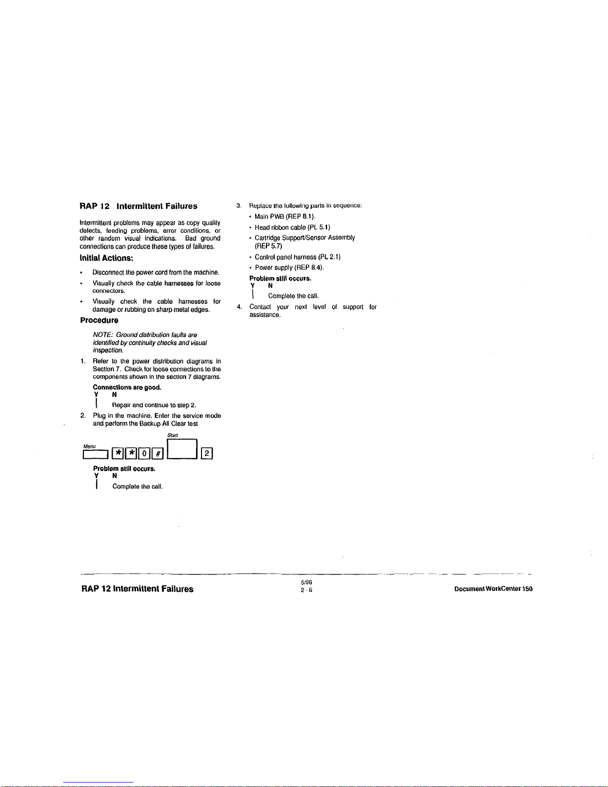
RAP 12 intermittent Failures
intermittent problems may appear as copy quality
defects. feeding problems, error conditions, or
other random visual indications. Bad ground
connections can produce these types 01 failures.
Initial Actions:
.
Disconnect the power cord from the machine.
* Visually check the cable harnesses for loose
connectors.
.
Visually check the cable harnesses for
damage or rubbing on sharp metal edges.
Procedure
NOTE: Ground distribution taults are
idenlilied by continuily checks and visual
inspection.
1. Refer to the power distribution diagrams in
Section 7. Check lor loose conneclions to the
components shown in the section 7 diagrams.
Connectlone ere good.
Y N
1 Repair and continue lo step 2,
2. Plug in the machine. Enter the service mode
and pedorm the Backup All Clear test
Problem
still
occurs.
i zomplete the call.
3. Replace the lollowing parts in sequence:
- Main PWB (REP 8.1).
+ Head ribbon cable (PL 5.1)
- Cartridge Support/Sensor Assembly
(REP 5.7)
- Control panel harness (PL 2.1)
- Power supply (REP 8.4)
Problem egll
occurs.
Y N
I
Complete the call.
4. Contact your next level 01 support for
assistance.
RAP 12 Intermittent Failures
5/96
2-6
Document WorkCenter 150
Page 27
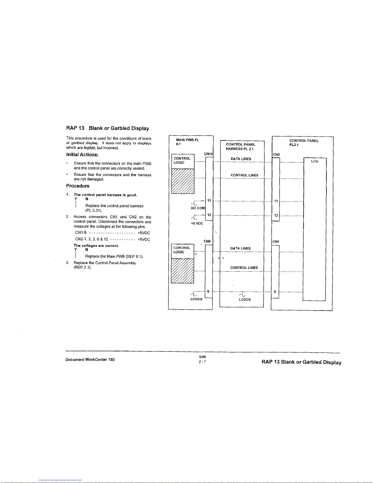
RAP 13 Blank or Garbled Display
This procedure is used for the conditions of blank
or garbled display. It does not apply to displays
which are legible, but incorrect.
lnitiai Actions:
* Ensure that the connectors on the main PWB
and the control panel are correctly seated.
* Ensure that the connectors and the harness
are not damaged.
Procedure
1. The control panel harness is good.
i ”
Replace the control panel harness
(PL 2.31).
2. Access connectors CNl and CN2 on the
control panel. Disconnect the connectors and
measure the voltages at the following pins.
CN1.6 _ _ ._ _ _. _ _ _. _ _ _. _. _ _.
+5”,,c
CNZ-1,2,3,6&12 ----------- +SVDC
The voltages are correct.
i N
Replace the Main PWB (REP 8.1)
3. Replace the Control Panel Assembly
(REP 2.1).
DC CD
-L
+5 “DC
CONTROL PANEL
HARNESS PL 2.1
DATA LINES
CONTROL LlNES
DATA LINES
CONTROL LINES
--
--
C
-
c
,
CONTROL PANEL
PLZ.1
:N2
-
LCD
Document WorkCenter 150
5196
2.7
RAP 13 Blank or Garbled Display
Page 28
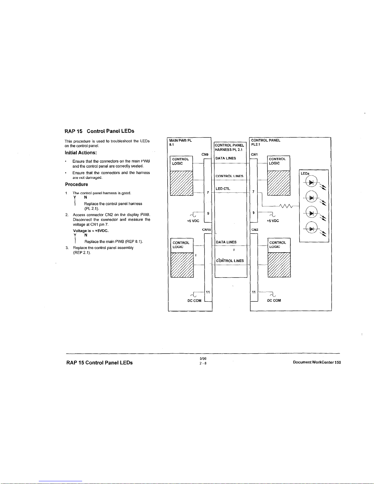
RAP 15 Control Panel LEDs
This procedure is used to troubleshoot the LEDs
on the control panel.
Initial Actions:
. Ensure that the connectors on the main PWB
and the control panel are correctly seated.
. Ensure that the connectors and the harness
are not damaged.
Procedure
1. The control panel harness is good.
1 N
Replace the control panel harness
(PL 2.1).
2. Access connector CN2 on the display PWB.
Disconnect the connector and measure the
voltage at CNI pin 7.
Voltage is = +5VOC.
i N
Replace the main PWB (REP 8.1).
3. Replace the control panel assembly
(REP 2.1).
MNN PWB PL
8.1
CN9
47
DC co
1
1’
M
:ONTROL’PANEL
1ARNESS PL 2.1
>ATA LINES
30NTROL LINES
LED CTL
DATA LINES
A
CbdTROL LlNES
ONTROL PANEL
L2.1
N2
1
-
RAP 15 Control Panel LEDs
5196
2-6
DocumentWorkCenter150
Page 29
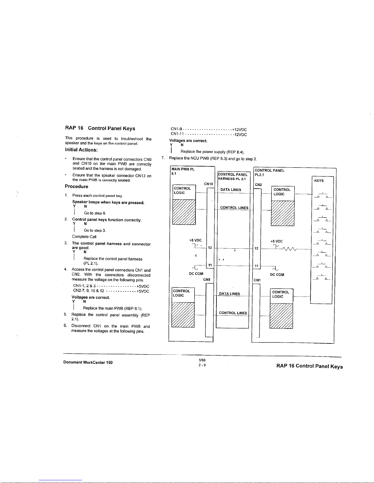
RAP 16 Control Panel Keys
This procedure is used to troubleshoot the
speaker and the keys on the control panel.
Initial Actions:
- Ensure that the control panel connectors CN9
and CNlO on the main PWB are correctly
seated and the harness is not damaged.
* Ensure that the speaker conneclor CN13 on
the main PWB is correctly seated.
Procedure
1. Press each control panel key.
Speaker beeps when keys are pressed.
i :o to step 6.
2. Control panel keys function correctly.
i :o to step 3.
Complete Call
3. The control panel harness and connector
are good.
i N
Replace the control panel harness
(PL 2.1).
4. Access the control panel connectors CNl and
CN2. With the connectors disconnected
measure the voltage on the following pins.
CN ,-1,2&S __._.._.__..___.. +~“,,c
CNZ-7.9,10&12 -------------+S”DC
Voltages are correct.
i N
Replace the main PWB (REP 8.1).
5. Replace the control panel assembly (REP
2.1).
6. Disconnect CNI on the main PWB and
measure the voltages at the following pins.
CN1.9 . . ..__._._......__.._ +,2”,,C
CN,-, ,
_ _ _. _ _ _ _. _ _. _ .,2”,3C
Voltages are correct.
i N
Replace the power supply (REP 8.4).
Replace the NCU PWB (REP 6.3) and go to step 2.
VlAlN PWS PL
1.1
+5 “DC
YL
6
DC COM
:ONTROL PANE,
IARNESS Pt. 2.1
DATA LINES
CONTROL LlNEl
DATA LINES
ZONTROL LINES
:ONTROL PANEL
+5 “DC
T+
DC COM
Document WorkCenter 150
U9S
2-9
RAP 16 Control Panel Keys
Page 30
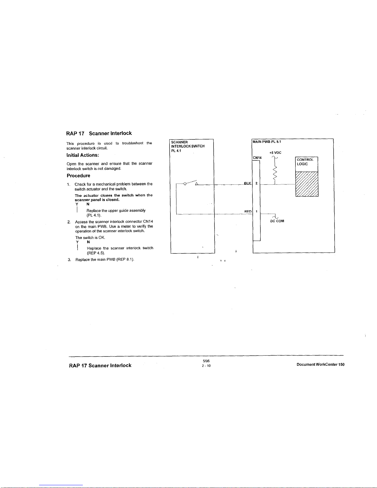
RAP 17 Scanner Interlock
This procedure is used to troubleshoot the
scanner interlock circuit.
Initial Actions:
Open the scanntx and ensure that the scanner
interlock switch is not damaged.
Procedure
1. Check for a mechanical problem between the
switch actuator and the switch.
The actuator closes the switch when the
scanner panel is closed.
i N
Replace the upper guide assembly
(PL 4.1).
2. Access the scanner interlock connector CN14
on the main PWB. Use a meter to verify the
operation of the scanner interlock switch.
The switch is OK.
i N
Replace the scanner interlock switch
(REP 4.5).
3. Replace the main PWB (REP 8.1).
s
:ANNER
IN
TERLOCKSWITCH
PI
_ 4.1
t
lW,lN PWB PL 0.1
14
i
DC COM
RAP 17 Scanner Interlock
5196
2-10
Document WorkCenter 150
Page 31

..~~. ..,,.
...~,::,,~
RAP 18 Paper Feeding
This procedure is used to troubleshoot printer
paper feed problems.
Initial Actions
* Disconnect the power cord and ensure that
there is no obstruction in the paper path.
* Clean the paper feed roller.
Procedure
NOTE: The circuit diagrams are OR the
following two pages.
1. Check fuse Fl on the main PWB.
Fl is OK.
i N
Replace the fuse (PL 8.1). If the new
fuse fails, go to step 7.
2. Check fuse F2 on the main PWB.
F2 is OK.
i N
Replace the fuse (PL 8.1). If the new
fuse fails, go to step 9.
3. Disconnect CN3 and CN4 from the main
PWB. Measure the voltage at the following
pins on the main PWB.
CN3.1~32 -._..___.___.__.._ +42VDC
CN4.j 8 2-. _ _. _ _. __ . _. _ +42vDC
Voltages are correct.
Y N
I
Perform RAP 10.
4. With connectors CN3 and CN4 disconnected,
measure the resistance between the pins.
Refer to Tables 4 and 5.
Resistance is OK.
i !epIace the defective motor
(REP 7.2 or REP 5.2).
5. Check the following components and
connections.
* ASF sensor and harness connector CN6
(REP 6.2).
* Encoder and harness connector (REP 5.4).
* Paper feed brake solenoid (RAP 27).
* Head ribbon cable and connectors (PL 5.1).
Components and connections are OK.
i Lpair or replace part
6. Replace the main PWB (REP 8.1).
7. Check the paper feed motor for mechanical
binding or incorrect reSi&ance (fable 2).
Motor is OK.
Y N
I
Replace the paper feed motor
(REP 7.2).
8. Replace the main PWB (REP 8.1).
9. Check the carriage motor for mechanical
binding or incorrect resistance (Table 1).
i
6
I/ t
Motor is OK.
i N
Replace the carriage motor (REP 5.2)
10. Replace the main PWB (REP 8.1).
Table 1 Carriage Motor
Table 2 Paper Feed Motor
Roller
Paper Feed Guide Assembly
Paper Feed Motor
Document WorkCenter 150
Si96
2-11
RAP 18 Paoer
Fc?wfinn
Page 32

SF SENSOR
L 6.1
r-
,A,N PWB PL 8.1
Cl
N
gy
4
Y
!
Y
5
Y
3
1 OF
F
2
-I
PAPER FEED MOTOR ON
EL
-42 VOC CLOCK
PAPER FEED MOTOR ON
EL +42 VDC CLOCK
‘EL
‘EL
PAPER FEED MOTOR ON
+42 VDC CLOCK
PAPER FEED MOTOR ON
+42 VDC CLOCK
IED
~42 “DC
IED
+42 VDC
J 1 1
6
1.
1.
Jl
1
RAP 18 Paper Feeding
5196
2.12
DocumentWorkCenterl50
Page 33

MAIN PWB PL cl.,
r
PAPER HEIGHT
SENSOR
iEAD RIBBON
:ABLE PL 5.1
MAIN PWB PL 8.1
C
CONTROL
r-l
LOGIC
(
l 5 w
,k
C
CI
-41
+SVDC
NS
d
1
‘2
-I
CARRIAGE MOTOR
fEL ON +42 VDC CLOCK
CARRIAGE MOTOR
IEL ON +42 VDC CLOCK
CARRIAGE MOTOR
,EL ON +42 VDC CLOCK
CARRIAGE MOTOR
IEL ON +42 VDC CLOCK
IED
+42 WC
IED
+42 WC
-
+l
t
ARRIAGE MOTOR
L 5.1
a20
ohms
ENCODER
ASSEMBLY PL 5.1
Document WorkCenter 150
5196
2-13
RAP 18 Paper Feeding
Page 34

RAP 20 Ink Cartridge
This procedure is used to troubleshoot the ink
cartridge.
CAUTtON
Do not the touch or put any adhesive (i.e.:
tape) on the nozzles of the ink cartridge.
They can be blocked or misaligned.
Procedure
1.
Move the
cartridge to the
center
(replacement) position.
2. Open the front cover and move the cartridge
lock lever to the rear of the machine.
3. Ensure that the head ribbon cable (PL 5.1)
between the main PWB and the carriage is
correctly seated and is not damaged.
4. Carefully reseat the ink cartridge and move
lhe lock lever toward ihe control panel.
5. If the problem still exists, replace the ink
c&ridge (PL 3.1).
RAP 20 Ink Cartridge
5/96
2-14
Document workcanter 150
Page 35

MAIN PWE PL 8.1
CARRIAGE PL 1.1
7
L-
6
5
12
1s
K-J
18
17
1s
14
13
R E
INK CARTRIDGE
PL 3.1
I
CNIS CN14 I
CN13
CNl2 /
INK HEAD
:ONTROL LOGIC
JK HEAD
OZZLES (128,
4
I
s I
Pin 1
Pin IO
/
CN2
Document WorkCenter 150
S/S6
2-15
RAP 20 Ink Cartridge
Page 36

RAP 21 Document Feeding
This procedure is used to troubleshoot a
document detection or a feed problem.
Initial
Actions
* Ensure that there is no document or other
obstruction in the document path.
* Open the scanner and ensure that the
actuator for the scan sensor is not binding.
Procedure
1. Use a meter to verify the operation of the
document sensors.
The sensors an? good.
i :eptace the sensor board PWB
assembly (REP 4.1).
2. Make a copy.
Document feeds through the scanner.
i :o to step 6.
3. ‘y”” image on the copy is good.
I N
Clean or replace the retard pad (REP
4.2) and clean the ADF, scan, and eject
rollers (PL 4.1).
4. Load 5 sheets into the ADF and press
Copy
then Start.
Observe operation for a mechanical problem
with the ADF feeder such as:
* A broken or damaged gear
* Binding switch actuator
* Contaminated feed rolls.
Operation is good.
; N
Repair or replace appropriate part.
5. Clean or replace the retard pad (REP 4.2) and
clean the ADF and eject rollers (PL 4.1).
6. Check the ADF motor for mechanical binding
or incorrect resistance (Table 1).
The motor is OK.
i N
Replace the ADF motor (REP 4.3).
7. Replace the main PWB (REP 8.1).
AIN PWB PL8.1
+5 “DC
t.
CNI
1
I
.-II-
2
5
r-
DC COM
CN2
Table 1 ADF Motor
Resistance
SENSOR BOARD ASSEMBLY
PL4.1
ADF SENSOR
-
MAIN PWB 8.1
RAP 21 Document Feeding
51%
2-1s
Document WorkCenter 150
Page 37

6
;I
ILK
ADF MOTOR ON +2O VDC CLOCK
IRN
ADF MOTOR ON +2O VDC CLOCK
IFI
ADF MOTOR ON +20 VDC CLOCK
)RN
ADF MOTOR ON +20 VDC CLOCK
7ED
342 VDC
6
RED
‘V *
+42 VDC
,DF MOTOR PL 4.1
400 400
ohms ohms
G300 G300
ohms ohms
400 400 1300 1300
/ /
ohms ohms ohms ohms
Document WorkCenter 150
5/96
2-17
RAP 21 Document Feeding
Page 38

RAP 23 Printer Comm Error
RAP 24 Dial Tone
This procedure is used to troubleshoot printer
communication errors.
Procedure
This procedure is used to troubleshoot failures
which do not provide dial tone at the telephone
handset.
Initial Actions:
1. Unplug the machine. Disconnect CNl from
the main PWB. Connect the meter across
pins 1 and 3 of the disconnected harness
connector. Plug in the machine.
There is +42 VDC present.
i N
Replace the power supply (REP 8.4).
2. Replace the main PWEI (REP 8.1)
Check that the telephone and telephone line
cables are correctly connected.
Ensure that the cables are not damaged
Procedure
1. Dial a telephone number and press Start
A dial tone is heard before the number is
dialed.
i N
Connect a telephone directly to the
telephone wall outlet.
2. Replace the main PWB (REP 8.1).
RAP 23 Comm, RAP 74 Dial Tone:
5196
Z-16
LlocumentWorkCenter1sl
Page 39

RAP 25 Dialing and Connecting
This procedure is used to troubleshoot failures of a
send operation from the machine. It does not
include image quality problems.
Initial Actions
* Check that the telephone line cable is
correctly connected.
* Ensure that the cable is not damaged.
- Ensure that the machine is set to the correct
dial mode; lone or pulse.
Voltages are correct.
Y N
I
Replace Main PWB (REP 6.1).
5.
Replace NCU PWB (REP 6.3).
6.
Connect another telephone to this telephone
line at the wall outlet. Use this telephone to
manually dial the remote machine.
The remote machine answers and sends a
ready tone back.
i N
Inform the customer of the telephone
line oroblem.
Procedure
7.
Replace the first telephone.
1. Use the external telephone to manually dial
the remote machine.
The remote machine answers and sends a
ready tone.
i :otostep6.
2. Locate the NCU PWE connector CN12 on the
main PWB. Measure the vollages at the
following pins.
(3.4,2-z, .____.___._.__...__. +,2”DC
CN,2-2 ~---~---~------~,z”DC
CNIZD,10,11&12------------+SVDC
CN,2-13 --~~_--~~--~~ py,,s,,DC
Voltages are correct.
i Lmstep4.
3. Replace the NCU PWB (REP 6.3).
4. Disconnect connector CN12 and measure the
voltages at the following pins on the main
PWB.
CN12-4,5,6&13 -------------+SVDC
CN,2.2 ~--------------~,zVDC~
cpJ,z.g . .._..._......_._.__ +,z”lJC
CNIZ-IO, 11 812---------- c.4VDC
n
#AiN PWB PL 8.1
r12 “DC
?-
+5 VDC
?-
J”
DC COM
DC
Cl
-.
--
CONTROL LINES
NW PWB PL 8.1
Document WorkCenter 150
z-19
RAP 25 Dialing and Connecting
Page 40

RAP 26 Transmit and Receive
6. Problem occurs only when remote machine initiates the transmission.
Errors
i N
The remote operator should call for service.
This procedure is used to isolate system
7. Ask the remote customer to contact the TELCO vendor for assistance.
components which contribute to on line
communications failures.
8. Turn off ECM and try the test again.
Initial Actions
The test completes normally without communications error codes.
* All normal system checks have been
i N
Contact the next level of support for additional assistance.
completed successfully.
9. Go to step 5.
Procedure
1
2,
3.
4.
I
5.
The problem occurs during a send
operation.
i :o to step 4.
Send a two page lest document to a known
good machine.
The test completes normally without
communications error codes.
i N
Contact the next level of supporl for
additional assistance.
Repeat the two page test with the machine
that caused the original problem.
If the
problem still exists, contact the next level of
support for additional assistance.
Receive two test copies from a known good
machine.
The test completes normally without
communications error codes.
i kAep8.
Repeat the two page test with the machine
that caused the original problem.
Test completes normally
without
communications error codes.
i N
The remote operator should call for
service.
‘~~,~, RAP 26 Transmit and Receive Errors
%~~~*;
‘%.
12196
2 20
Document Workcenter 150
Page 41

RAP 27 Paper Feed Brake Solenoid
Procedure
1. Measure the voltage at CNS, pin 1.
Voltage meaS”ree = +5vtx.
i :o tcl step 4.
2. Make a copy
The voltage at CNS-1 decreased to
approximately 0 VDC when the paper was
feeding.
i !eplace the main PWB (REP 8.1).
3. Ensure the solenoid actuator mechanism is
operating properly.
4. Measure the voltage at CNB, pin 2.
Voltage meas”res li/ +5voc.
I-
i f:eplace the main PWB (REP 8.1).
5. Disconnect CNS. Set the meter to meewre 64
ohms. Connect the meter across pins 1 and 2
of the disconnected connector CNS.
i
There is approximately 64 ohms present. 1
i N
s ,
Go to Flags 1 and 2 and check for an
open connection. If OK, replace the
paper feed roller brake solenoid (P/O
Side Frame) (PL 7.1).
6. Go to Flag 1 and check for a short circuit. If
shorted replace the paper feed roller brake
solenoid (P/O Side Frame) (PL 7.1).
Document WorkCenter 150
5196
2-21
RAP 27 Paper Feed Brake Solenoid
Page 42

RAP 28 Mechanical Checkout
The following procedure applies to all gears,
shafts, rollers. springs. and bearings in these
=W?S.:
.
Upper and lower scanner
* Printer
Initial Actions
Disconnect the power cord,
Procedure
NOTE: Lubrication is only added or
replaced on those components which
were originally lubricated as
manufactured.
1. Inspect all of the following. Replace any pari
that is binding or damaged.
* shafts, shaft supports, or bearings
* cover latch spring or latches.
Assembly
Assembly
RAP 28 Mechanical Checkout
~-
DocumentWorkCenter150
Page 43

3 Image Quality Repair Analysis Procedures
Section Contents
Title
Page
lntro&ction.. _ _ _ _ _ _ . _ _ _ _ . _ _ _. _. _ _ 3.1
Measureme”ts . _. _ _ - - -. _ _ _ _ -. _. _ _ -3-1
Image Quality Test Pattern - - - - - - - - - - -3-2
IQ RAP 1 Entry Image Quality RAP - - - - - 3-3
IQ RAP 10 Blank or mostly blank print - - - - -3-4
IQ RAP 12 Vertical/horizontal deletionsllines 3.6
IQ RAP 14 Dark image 2 inches wide - - - - - - 3.7
IQ RAP 15 Black with thin deletions - - - - - -3-7
IQRAP16 Blackprint-----------------3-S
IQ RAP 17 MisregistrationlSkew- - - - - -3-9
lQRAP18 Printdensity---------------3-10
IQ RAP 23 Gray or mostly gray copy - - - - 3.11
IQRAP30 V-bars ___..____.______.._ 3-1,
IQ RAP 31 Blurry, Fuzzy I Smudged Image- 3-12
IQ RAP 32 Image quality is unacceptable - - 3-13
Introduction
The Image Quality (IQ) section is used to identify
image quality problems.
It conlains the
Introduction, Image Quality samples, and Image
Quality RAPS.
The sample is a reproduction of the image quality
test pattern 82P151.
Compare the image quality of the samples
produced in section 1, System Checks, with the
82P151 test pattern in your kit. This will identify
any image quality defects which may have been
produced during Off-line or On-line System
Checks.
Use the Image Quality RAPS to further diagnose
machine problems.
In the YIN C/es/No) steps of the RAPS. a Yes
response will lead you to the next step. A No
response will indicate a corrective action, or will
direct you to another step. When the ihdicated
corrective action ‘has been completed, go to
Section 1 and restart the Syste& Check to verify
that the problem has been corrected.
Measurements
Power and signal grounds are connected to frame
ground, therefore all circuit troubleshooting can
be performed using the metal frame (chassis) as
the grounding point.
If more information is
needed to locate connectors or test points, refer
to section 7.
NOTE: Make aft voltage measurements
to ground unless instructed to measure
from “W to “xx’:
Unless specified otherwise. the following voltage
tolerances are used within this section:
St&d. __ _ _. . - - -. _. . _. _. . _ .,&as”&
+5.0VDC---------t4.75VDCto+5.25VDC
+12.0 VDC - - - - -+ 10.8 VDC to + 13.2 VDC
-12.0 VDC - - - - - - -10.8 VDC to -13.2 VDC
+ 42.3 VDC - - - -+37.8 VDC to +46.2 VDC
O,OV,,C .____..__._.. _ . ..__._ +O,s,,DC
Document
WorkCenter 150
Section Contents
Page 44

Image Quality Test Pattern
Image Quality Test Pattern
5/96
3-2
Document WorkCenter 150
Page 45

IQ RAP 1 Entry Image Quality RAP
Procedure
G
1. Enter It10 wvice mode and print the internal test pattern.
SlOtI
8,
&,
2. Make a copy of test pattern 82P151.
3. Determine which mode caused the defect,
4. Read through Ihe list of defecls and select the best description of Ihe
defect.
5. Go to the RAP or IQ RAP indicated in Table 1.
Table 1 Image Quality Defects
IMAGE QUALITY DEFECTS
Blank or mostly blank print
Gical I Horizontal deletions I tines
Dark image 2 inches wide
Black with thin deletions
Black print
MisregislrationlSkew
Prinl densily
Stretched copy
Gray or mostly gray copy
V-bars
Blurry, fuzzy or smudged image
Image quality is unacceplable
RAP
IO RAP 10
ICI RAP 12
IQ RAP 14
ICI RAP 15
IQ RAP 16
IQ RAP 17
IQ RAP 18
RAP 21
IQ RAP 23
IQ RAP 30
IQ RAP 31
IQ RAP 32
Document Workcenter 150
3-3
IQ RAP 1 Entry image Quality RAP
Page 46

IQ RAP 10 Blank or mostly blank print
I
Initial Action
- Check CIS tuning (see Section 6).
Procedure
1. The internal test pattern Is good.
i N
. Ensure that lhe ink cartridge is installed correctly.
* Prime the Ink Cadridge.
a Ensure that the head ribbon cable (PL 5.1) is not damaged.
* Ensure that all connections are correct on the main PWB.
* Ensure that the maintenance station (PL 5.1) &ds correctly to the
ink cartridge.
* Ensure that the pump system (PL 6.1 I7.1) Is working correctly.
* II the problem slill exists. replace the following pads in sequence:
. ink cartridge (PL 3.1).
- main PWB (REP 6.1).
2. Ensure that connections CN5 8 CN15 are correct on the main PWB.
Co”“ectlon Is correct.
i Repair or reconnect CNt5.
3. Perform the following actions:
. Clean lhe scan. ADF. and eject rollers.
* Remove the scanner assembly and check lor an obstruction in the optical
path. Clean or repair as required.
The problem has been corrected.
i N
Replace the scanner assembly (REP 3.4).
4. Complete the call.
M
IAIN PWB PL 8.1
CARRIAGE PL 5.1
+5 VDC
CN!
2
1
17
DC cm
”
-----I-
I
I
HEAD RIBBON
CABLE PL 5.1
:N1,2
‘“1
I-
INK
CAATRtDGE
11
/
PL 3.1
9
13
16
17
16
CARRIAGE
IQ RAP 10 Blank or mostly blank print
3/98
3-4
Document WorkCenter
Page 47

MAIN PWB PL 8.1
CONTROL
r-l
LOGIC ‘~
-L-
+5 “DC
-t
DC COM
-12 “DC
42 VDC
5
-D
c
,
ATA LINES
LED ARRAY ON
(L, +5 VDC
ONTROL LINES
SCANNER ASSEMBLY
‘L3.1 _
I
Cl.5 ASSY
PL 4.1
-;L
DC COM
7
-12 VDC
7
+,2 VDC
Document WorkCenter 150
3-5
IQ RAP IO Blank or mostly blank print
Page 48

IQ RAP 12
Vertical I horizontal deletions I lines
Procedure
1. The internal test pattern is good.
i N
I . Ensure that the reverse spring is attached to the slip spring and
frame.
. Ensure that the ink cartridge is installed correctly.
- Ensure that the connectors are not damaged and are correctly
seated on the main PWB.
*
If the problem exists after periods of non use. check that the
Maintenance Station to cartridge seal is not damaged and the
Prime function/pump system isworking correctly (PL 5.1 PL 7.1).
* Prime the cartridge. More than one time may be required.
- If the problem still exists, replace the ink cartridge (PL 3.1)
* Perform RAP 27 Paper Feed Brake Solenoid.
2. Perform the following actions:
* Clean the scan. ADF, and eject rollers
* Remove the scanner assembly and check for an obstruction in the optical
path. Clean or repair as required.
I * Ensure that the earth spring is making contact with the ends of the ADF
roller, scan roller and eject roller.
The problem has been corrected.
i N
Replace the scanner assembly (REP 3.4).
3. Complete the call.
IQ RAP 12 Vertical I horizontal deletions I lines
3-6
Document WorkCenter 150
Page 49

IQ RAP 14
Dark image 2 inches wide
IQ RAP 15 Black with thin deletions
Initial Action:
Initial Action:
.
Ensure that the ink cartridge is installed correctly.
- Ensure that all connectors are correctly seated on the main PWB.
* If the problem still exists, replace the ink cartridge (PL 3.1).
*
Ensure that the ink cartridge is installed correctly.
’
Ensure that all connectors are correctly seated on the main PWB
*
If the problem still exists, replace the ink cartridge (PL 3.1).
HEAD RIBBON HEAD RIBBON
CABLE PL 5.1 CABLE PL 5.1
CN112
CARRIAGE PL 5.1
Document WorkCanter 150
5196
3-7
IQ RAP 14, IQ RAP 15
Page 50

IQ RAP 16
Black Print
Procedure
I. The internal test pattern is good.
i N
. Ensure that the ink cartridge is installed correctly.
* Ensure that all connectors are correctly seated on the main PWB.
* If the problem still exists, go to step 3.
2. Ensure that connection CN15 is correct on the main PWB.
Connection is correct.
i :epair or reconnect CN15.
3. Replace the parts in the sequence listed:
* ink cartridge (PL3.1).
* main PWB (REP 8.1)
HEAD RIBBON
CABLE PL 5.1
-
-.
1
CARRIAGE PL 5.1
SNIIZ
7
I-
INK
CARTRIDGE
11
!-
PL 3.1
9
13
16
17
16
2
J
MAIN PWB PL 8.1
-c-
+5 VDC
q-
DC COM
.4r-
-12 “DC
s *c-
+I2 VDC
IATA LINES
LED ARRAY ON
(L) +S VDC
ONTROL LINES
-2
DC COM
4
+I2 VDC
IQ RAP 16 Black Print
5196
3-8
Document WorkCenter 150
Page 51

IQ RAP 17 Misregistration I Skew
This RAP is used if the image is not correctly positioned on the paper either top
- lo - bottom or side . to - side.
Q: Procedure
The internal lest pattern is good.
1 N
e Ensure lhal there is no obstruction in Ihe paper palh.
. Ensure that the copy paper ts loaded correctly. The edges are
even, the paper guides do not inlerfere wilh lhe paper movemenl,
and lhere are less lhan 100 sheols in Ihe Iray.
- If Ihe problem slill exists, gc lo slep 4.
6,, 2.
3.
4.
5.
Clean Ihe scan. ADF, and ejecl rollers. Check lhal Ihe document guides
are adjusled against Ihe document and lhal Ihe guides hold the
documenls, bul do nol interfere wilh Ihe document movemenl.
i N
Repair and retry Ihe operalion.
Ensure thal there no obslruclion In the documenl leeder. Ensure lhat lhe
documenl guide, document dettector, and document stop are not
interfering with the correct movement of the documents. Check that the
dccumenl and scan sensors are installed correctly and that the senwr
actuators mcve Ireely.
i N
Repair and retry the operation.
Perform the grid adjust (ADJ 5.1) procedure.
If the problem still exists, replace Ihe main PWB (REP 8.1).
Document WorkCenter 150
IQ RAP 17 Misregistration I Skew
Page 52

IQ RAP 18 Print density
This RAP is used il Iho image densily is not unilorm.
Initial Actions:
I*
Check CIS Tuning (see Seclion 6).
* Sel the graphic densily lo 300 dpi (A&r lo the Dos Print Setup Oplions in
the users guide Chapter 6, “Prinler Conlrol and Configuration”).
.
Sol draft mode off (Refer lo Ihs users guide Chapter 6, ‘Prinler Conlrol and
Conliguralion”).
* lnspecl lhe paper qualily and inslall fresh paper.
* Check lhat Ihe head gap arm is posilionsd in Ihe gap lever on Ihe lronl
cover, and lhat Ihe gap lever is correclly positioned lor Ihe print material.
Procedure:
1.
2.
3.
4.
5.
6.
The internal lest pallern is good.
i Llstcp3.
Ensure the scanner slol is clean and replace the scanner assembly
(REP 3.4).
Prime Iha ink cartridge and reprint Ihe inlet”4 test pattern.
The lnlernal test
paller” is
good.
i :mep5.
Check Ihat the main\enance stalion to cartridge seal is not damaged and
Ihe prime lunclionlpump system is working correctly.
i N
Replace parts as required (PL 5.1 - PL 7.1)
Verily (he ink cartridge latch is not damaged.
The ink cartrldge latch is good.
i N
Replace the cam pin (REP 5.6), lhen Ihe cartridge supporVsensor
assembly (REP 5.7), (hen the carriage assembly (REP 3.5).
Check Ihe head gap adjuslment (ADJ. 5.2).
The adjuslment Is correcl.
i Idjrrs, Ihe head gap.
7. Enter the service mode and perlorm Ihe all backup clear procedure.
CAUTION
The programmed data and any documents h msmmy will be deleted.
The internal test pattern Is good.
i N
Replace Iha following pads 1” sequence:
f main PWB (REP 6.1).
- printer assembly (REP 3.2).
6. Complele (he call.
IQ RAP 18 Print density
3.10
Document WorkCenter 150
c
Page 53

IQ RAP 23
Gray or mostly gray copy
Initial Actions
&! ,:
Ensure Ihal CN15 is correclly connected to Ihe main PWB.
Check CIS Tuning (see Seclon G).
Procedure
1. The Internal test palter” IS good.
g&
i ~oIostep4.
2. The scan roller and the scanner 5101 are clean.
i :,,a” the areas.
3. Replace the CIS assembly (REP 4.4).
4. Replace lhe inkcartridge (PL 3.1).
The Internal lest paltern is good.
i
:eplace the main PWB (REP 8.1).
5. Complete the call.
IQ RAP 30 V-bars
This RAP is used if the image is missing wilh black vertical lines or bars and
relates only lo copy qualily of a fax operation.
Initial Actions
Ensure that lhe telephone line cord is connecled correctly.
Procedure
1. Transmit a document over a known good telephone line.
The Image is good.
i N
Replace the main PWB (REP 8.1).
2. The transmission line needs lo be lesled.
Documenl WorkCenler 150
IQ RAP 23 Gray or mostly gray copy
Page 54

IQ RAP 31 Blurry, Fuzzy, or Smudged Image
Procedure
1. The lnlernal test pattern is good.
i kJslep5.
2. lnspecl the original document and check that Ihe document guides are
adjusled correclly against the document.
Document and guides are okay.
i *
Replace original or adjust Ihe guides.
3. lnsp& lhe documenl feeder and enwre lhal Ihare is no obstruclion in lhe
scanner area.
Document feeder and scanner are clean.
i *
Clean the scanner area and Ihe scan, ADF. and eiecl rollers.
4. Replace the ADF motor (REP 4.3).
5. Inspect the lollowing ilems:
* Ensure the prinl paper has a smooth surface.
* Ensurs lhal Ihe ink cartridge is installed correctly.
* Ensure the Gap Lever is set cortecUy.
* Perform ADJ 5.3 Head Gap.
* Check that Ihe maintenance Nation lo cartridge seal is not damaged and
lhe prime funclion / pump syslem is working correclly (PL 5.1 . PL 7.1).
l
Prime the printer.
* Replace the ink cartridge (PL 3.1).
l
If problem slill exists, perform RAP 27 Paper Feed Brake Solenoid.
IQ RAP 23 Gray, IQ RAP 30 V-bars
Page 55

IQ RAP 32 Image Quality is Unacceptable
Initial Actions
1. Establish voice contact using the same telecommunication link used to
transmit the document. if possible.
The line is quiet and a normal voice can be heard clearly.
i N
The telephone company must verify the quality of the
telecommunication link.
2. The original document tfvat was transmitted is clean and has no
defects.
i :se a good document.
3. The document was transmitted with Superfine resolution selected.
i N
Retransmit the document with Superfine resolution selected.
4. Print the phone book
5. Print the menu map
NOTE: Do not perto”” a memory clear unless absotutety necessary.
6. Enter service mode and perform the all backup clear procedure.
S,M
The programmed data and any documents in memory will be deleted.
Document WorkCenter 150
S/96
3-13
IQ RAP 32 Image Quality is Unacceptable
Page 56

Notes
Notes
5196
3-14
Document workcenter 150
Page 57

4 Repair/Adjustment
Section Contents
Carriage Assembly
introduction
Covers and Trays
REPl.lFrontCover ---.-----_
REP 5.1 Wipers Blades and Blotters - - - - - 4-22
REP5.2CarriageMotor.--------------4-23
REP 5.3 Maintenance Station. - - - - - - - 4-24
REP 5.4 Encoder Assembly - - - - - _ - - - 4-25
REp5.5Carriage __....-.. _ ..__..._._ 4.26
REP5.6CamPin _.__ I _.__ _ .____ _ _.__ 4-28
REP 5.7 Cartridge SupportlSensor AssemblyC30
Paper Feed Assembly
REPl.ZRearCover ----------------s-4-4
Control Panel
REP 2.1 Control Panel Assembly -. - - - - - - -4-5
REP 2.2 Document Exit Guide - - - - - - - - - -4-6
Scanner and Printer Systems
REP 3.1 Printer and Tray Assembly - - - - - -4-7
REP 3.2 Printer Assembly - - - - - - - - - - - - 4-6
REP 3.3 Scanner and Guide Assembly - - - - -4-9
REP3,4ScannerAssembly----------- 4-10
REP 3.5 Carriage Assembly - - - - - - - - - 4-11
REP 3.6 Side Frame Assembly - - - - - - - - - -614
ADF and Scanner Assembly
REP 4.1 Sensor Board PWE Assembly - -4-16
REP4,2RetardPad------------------4-17
REP4.3ADFMotor------------------4-16
REP4,4CISAssembly----------------4-19
REP 4.5 Scanner Interlock Switch - - - - - - - _ 4-20
REP 4.6 ADF, Scan and Eject Rollers - - - - -4-21
REP6,lPaperFeedRoller-------------4-31
REP 6.2 ASF Sensor Cam and ASF Trays 4-32
REP6.3TankandSeal ----------M----4-33
Side Frame
REP7.,P”,,,p _.____.______.___.__-. 4-34
REP 7.2 Paper Feed Motor- - - - - - - - - - - - - 4-35
I
Electrical Components
REP&lMainP~ _-__-,__- y.‘. _____. 4-36
REP&ZEPR‘,Ms--ss ______.___ ____ 4.37
REP6,3NC”P,,,,,3-- ___..______.___. 4-36
REP6,4PowerSupply----------------4-39
REP,j,5Sp&er---- _--.._.___ _ _____ .,.,$O
Adjustments
ADJ5,lGridAdjust------------- ---.- 4.41
ADJ5.2HeadGap------------- ----.- 4-42
ADJ 5.3 Home Position Sensor Plate - _ - - - 4-45
Document WorkCenter 150
5/96
4-I
Section
Contents
Page 58

introduction
Overview
The Repair I Adjustment section, Section 4 of the
Service Manual, provides information that enables
the Service Representative to restore the product
to within specification after fault isolation.
Section Contents
The Section Contents lists, in sequence, all the
items of the section, with page references. Each
entry in the section contents appears exactly as it
appears in the manual.
Repair Procedures
This repair subsection contains instructions for
removal and replacement tasks. A removal and/or
replacement task is included when it is not obvious
how components are removed and replaced. or
when special conditions (such as an adjustment)
must be met during these tasks.
Step-by-step removal procedures for a specific
component or assembly are provided.
A good. general procedure to follow for most
repairs is to remove the handset and cradle. Also,
disconnect all the modular cables from the
machine.
Illustrations are used to assist you with the
procedures. You should refer to the specific Parts
List illustration (listed under the repair title) for
locating most components within a procedure.
Adjustment
The adjustment subsection consists of a complete
set of instructions for performing independent
adjustment tasks.
The title of each independent adjustment is in
boldface type. Under the title, the adjustment task
contains the following sections:
Purpose
The Purpose of the adjustment task states the
reason for performing the adjustment.
Gflak
The Check defines the quickest way to determine
whether the adjustments are within specification.
A check is used only when it is possible to
determine that the component is within
specification without disturbing the adjustment.
The Adjustment contains complete instructions for
performing the adjustment task,.
I
6
‘S ,
Introduction
5196
4-2
Document WorkCenter 150
Page 59

REP 1 .I Front Cover
Parts List on PL 1.1
Removal
WARNING
Dii;;tnnect the Power Cord from the
1. Disconnect the Power Cord from the outlet.
2. Remove the Paper Tray.
3. Remove the Front Cover (Figure 1).
4. Note the position of the Gap Lever, front or
rear position.
5. Open Front Cover and remove the E-Ring
from each of the Front Cover pivot
QOStS.
6. Slide the Front Cover off of the pivot posts
one side at a time.
Replacement
CAUTION
Ensure fhs Gap Lever is engaged wifh Ihe
Prinfsr Gap Ann and fhe Gap Lever is
Mumed to the pailion
nofed in
skp 4.
1. Reinstall the components in the reverse order.
Front Cover
Figure 1
~Removing the Front Cover
Document WorkCenter 150~
5,96
4-3
REP 1 .I Front Cover
Page 60

REP 1.2 Rear Cover
Parts List on PL 1.1
Removal
WARNING
Disconnect the Power Cord from the
outlet.
1. Disconnect the following:
a. Power Cord.
b. Parallel Cable.
c. Telephone Cables.
2. Remove the Paper Tray.
3. Remove the 3 screws retaining the Rear
COVf3.
4. Slide the Rear Cover off, disengaging the 4
tabs from the Bottom Pan (Figure 1).
Replacement
1. Ensure the 4 tabs engage the Bottom Pan
slots.
Figure 1
Disengaging the tabs
REP
1.2
Rear Cover
U96
4-4
Document WorkCenter 150
Page 61

REP 2.1 Control Panel Assembly k,
Parts List on PL 2.1
Removal
WARNING
Disconnect the Power Cord from the
outlet.
1. Remove Front Cover (REP 1.1).
2.
Remove the Control Panel (Figure 1).
a. Open the Control Panel.
CAUTION
The flexible fab on the right side pivot w;//
break if overllexed.
b. Slide the Control Panel to the right.
c. Slide the Control Panel off of the left
pivot.
d. Slide the Control Panel off of the right
pivot.
3. Disconnect the cable connector.
Replacement
1. Reinstall the components in the reverse order.
Figure I
Removing the Control Panel Assembly
5/96
Document WorkCenter 150
4-5
REP
2.1 Control Panel Assembly
Page 62

REP 2.2 Document Exit Guide
Parts
List on PL 2.1
Removal
WARNING
Disconnect the Power Cord from the
outlet.
1. Remove the Front Cover (REP 1 .l).
2. Remove the Control Panel Assembly
(REP 2.1).
3. Remove the Document Exit Guide
(Figure 1).
NOTE: Lift the Fmnt of the machine to
grip the tower edge of the Exit Guide.
a. Grip the lower edge of the Exit Guide and
pull down.
b. Gently rotate up to disengage the tabs
(both sides).
c. Disengage the upper tabs.
d. Remove the Document Exit Guide.
Replacement
1. Reinstall the components in the reverse order.
*
Figure I, ,
Removing the Document Exit Guide
REP 2.2
Document Exit Guide
5,536
4-6
Document WorkCanter ?60
Page 63

Parts List on PL 3.1
Removal
WARNING
Disconnect the Power Cord from the
outlet.
1.
2.
Remove the Rear Cover (REP 1.2).
Remove the Printer and Tray Assembly
(Figure 1).
a. Remove the two (2) mounting screws -
one
on each side.
b. Open the Control Panel.
c. Slide the Printer and Tray Assembly
toward the Document Exit Guide to
disengage the tabs.
NOTE: Cables to the
Main
PWB may
become disconnected during the next
step. Observe
cable
connector locations
andpoladfy
of the flex cable CN5 during
disassembly.
d. Lift the rear of the Printer and Tray
Assembly and tilt to access the cables.
a. Disconnect cables at CN3, CN4, CN5.
CN6, CN7. and CNS.
1. Ensure all cable connections are fully seated.
2. Reinstall the componenta in the reverse order.
Figure I
Removing the Printer and Tray Assembly
NOTE: Forctadt& the Front Coverand Control Pane/ are not shown.
Document WorkCenter 150
9/W
4-7
REP 3.1 Printer and Tray Assembly
Page 64

Removal
WARNING
Disconnect the Power Cord from the
outlet.
1. Remove the following:
a. Rear Cover (REP 1.2).
b. Printer and Tray Assembly (REP 3.1).
c. Paper Feed Guide.
2. Remove the Printer Assembly (Figure 1).
a. Loosen the screws and remove the Lever
stop Plate.
b. Loosen the screws and remove the Left
and Right Ground Clips.
Replacement
1. Route all of the Printer Assembly cables
through the openings in the Printer Tray.
2. Reinstall the remaining components in the
r.sver.se order.
Printer Assembly
Figure 1
Removing the Printer Assembly
REP 3.2 Printer Assembly
5/96
4-8
Document WorkCenter 150
Page 65

REP 3.3 Scanner and Guide Assembly k,
Parts List on PL 3.1
Removal
WARNING
Dlsconnecl the
Power Cord from the
outlet.
1.
Remove the following:
a. Front Cover (REP 1.1).
b.
c.
t; d.
Rear Cover (REP 1.2).
Control Panel Assembly (REP 2.1).
Document Exit Guide (REP 2.2).
Prinler and Tray Assembly (REP 3.1).
2. Remove the Scanner and Guide Assembly
from the Bollom Pan (Figure 1).
a. Disconnect conneclors CN2. CNll,
CN14, and CN15.
b.
Remove the two (2) ground cable scrws.
c. Remove the two (2) mounting screws.
d. Lilt the Scanner and Guide Assembly.
Replacement
1. Ensure that the Scanner Motor harness is
dressed away
from Ihe Scanner gears.
2.
Reinslall the components in the rewse order.
Figure 1 Removing Ihe Scanner and Guide Assembly
Document WorkCenter 150
5,X3
4-9
REP 3.3 Scanner
and
Guide Asselnbly
Page 66

REP 3.4 Scanner Assembly
Parts List on PL 3.1
Removal
WARNING
Disconnect
the Power Cord from the
OUllFA.
1. Remove the following:
a. Front Cover (REP 1.1).
b. Rear Cover (REP 1.2).
c. &ntrol Panel Assembly (REP 2.1).
d. Document Exit Guide (REP 2.2).
B. Printer and Tray Assembly (REP 3.1).
I. Scanner and Guide Assembly (REP 3.3).
2. Remove the Scanner horn the Lelt and Right
Guides (Figure 1).
Replacement
1. Ensure that all cables on Ihe left side are
routed between the Lelt Guide mounting
bosses.
2. Reinstall the componenls in lhe reverworder.
copy quality and accomplish CIS
necessary (see Section 6).
Figure
1
Removing the
Scanner
Page 67

REP 3.5 Carriage Assembly
Parts List on PL 3.1
CAUTION
Leavinq the Ink Catiddae removed for long
m ink nozzles to
periods of time will cause iI
dry out. Image qualily pmblems or a blank
print could resdlt. If nece.ssa& prime the Ink
C&ridge after reinstallation.
1.
Disconnect the Power Cord from the outlet.
2.
Remove the following:
a. Ink Cartridge Cover (PL 3.1).
b. Ink Cartridge.
c. Rear Cover (REP 1,2).
d. Printer and Tray Assembly (REP 3.1).
e. Printer Assembly (REP 3.2).
3. Disconnect the maintenance tube from the
tank (Figure 1).
Maintenance Tube
Figure 1
Disconnecting the Maintenance Tube
Document WorkCenter 150
5/96
4-11
REP 3.5 Carriage Assembly
Page 68

4. Turn the Printer Assembly over.
5.
Release the cable from the clamp (Figure 2)
Release Cable
Figure 2
Releasing the Cable
6. Turn the Printer Assembly over.
7. Remove the Carriage Assembly (Figure 3).
Figure 3
Removing the Carriage Assembly
REP 3.5 Carriage Assembly
5/96
4-12
Document WorkCenter 150
Page 69

Replacement
1. Ensure the Carriage Assembly engages the
slot in the Printer Assembly which is located
just above the Tank (Figure 4).
2. Ensure that the Pump Tube is routed to avoid
restrictions.
3. Reinstall the remaining components in the
reverse order.
Adjustments
1. Head Gap (ADJ 5.2).
2. Grid Adjust (ADJ 5.1).
3ot in
+inter
Figure 4
Engaging slot in Printer Assembly
Document WorkCenter 150
5196
4-13
REP 3.5 Carriage Assembly
Page 70

REP 3.6
Side Frame Assembly
Part List on PL 7.1
CAUTION
Leaving the Ink Carbidge removed for tong
periods of time will cause the ink nozzles to
dry out. Image quality problems or a blank
print could iaesult. If necessary, prime the Ink
Cartddge after reinstallation.
1. Disconnect the Power Cord from the outlet.
2. Remove the following:
a.
Ink Cartridge Cover (PL 3.1).
b. Ink Cartridge.
c.
Rear Cover (REP 1.2).
d.
Printer and Tray Assembly (REP 3.1).
a.
Printer Assembly (REP 3.2).
3. Remove the Side Frame Assembly
(Figure 1).
a.
Disconnect the Pump tube.
b. Remove the three (3) Side Frame
Assembly mounting screws.
c.
Carefully pull the Side Frame Assembly
out to access the Reverse Spring.
d.
Dismnnect the Reverse Spring.
e.
Remove the Side Frame Assembly.
Figure 1 Removing the Side Frame Assembly
REP 3.6 Side Frame Assembly
S/S%
4-14
Document WorkCenter 150
Page 71

1. Rotate the Paper Feed Roller and Slip Ring
Spacer to the front towards the
Carriage
Assembly (Figure 2).
Spacer
Figure 2
Rotate Paper Feed Roller and
Slip Ring Spacer
2. Rotate the ASF Cam Gear until the ASF Trays
are in the down position and the ASF Cam
Gear is as shown (Figure 3).
3. Install the Side Frame Assembly,
a.
b.
c.
d.
e.
f.
Carefully insert the Side Frame
Assembly.
Slide the Side Frame Assembly back
out just far enough to allow alignment of
the Lift Gear to the ASF Cam Gear.
Align the marks on the gears as shown
(Figure 4).
Secure the Side Frame Assembly with
the three (3) screws.
Install the Reverse Spring oriented as
shown (Figure 5).
Reinstall the Pump. tube to the inlet pelt
(Figure 6).
4. Reinstall the remaining components in the
n?“er~e order.
Pointer on
ASF
Figure
4 Align marks on gears
Adjustments
5. Head Gap (ADJ 5.2)
6. Grid Adjust (ADJ 5.1)
Paper Feed
Roller Gear
Figure 5
install Reverse Spring
Pump Tube
ASF C8m Gear
Figure 6
Install Pump Tube
Figure 3
Rotate ASF Cam Gear
5196
Document workcenter 150
4-15
REP 3.6 Side Frame Assembly
Page 72

REP4.1
Sensor
PWB k,
Parts List on PL 4.1
Removal
WARNING
Disconnect the Power Cord at the outlet
1. Remove the following:
a. Front Cover (REP 1.1).
b. Control Panel Assembly (REP 2.1)
c. Document Exit Guide (REP 2.2).
2. Remove the Scanner Cover from the Upper
Guide (Figure 1).
a. Open the Upper Scanner Guide.
b. Release the tabs and remove the
Scanner Cover.
3. Remove the Sensor Board PWE Assembly
(Figure 1).
a. Discamect the Sensor Board Cable
connector, CNl
b. Remove the board.
Sensor PWB
Scanner Cover
w
‘Figure 1
Remjxing the
Sensor
h
e r
Replacement
4. Reinstall the components in the reverse order.
REP 4.1 Sensor PWB
S/96
‘l-16
Page 73

REP 4.2 Retard Pad
Parts List on PL 4.1
Removal
1. Open the Control Panel.
2. Remove the Retard Pad Assembly
(Figure 1).
a. Remove the mounting screw.
b. Open the Scanner Cover.
C. Press tabs and remove the Retard Pad
assembly.
Replacement
1. Reinstall the components in the reverse order.
Figure 1
Removing the Retard Pad
Document WorkCenter 150
5196
4-17
REP 4.2 Retard Pad
Page 74

REP 4.3
ADF Motor k,
Parts List on PL 4.1
Removal
WARNING
Disconnect the Power Cord from the
outlet.
1. Remove the following:
a.
Front Cover (REP 1.1).
b.
Rear Cover (REP 1.2).
c.
Control Panel Assembly (REP 2.1).
d.
Document Exit Guide (REP 2.2).
e.
Printer and Tray Assembly (REP 3.1).
f.
Scanner and Guide Assembly (REP 3.3).
9.
Scanner Assembly (REP 3.4).
NOTE: The ADF Motor flange is used to
hold the gears in place. Use care when
removing the motor so that the gears and
spacer stay in place.
2. Remove the ADF Motor (Figure 1).
Replacement
1. Reinstall the ADF Motor with the wires toward
the front of the machine.
2. Reinstall the remaining components in the
rever.se order.
I
d
:s 8
Figure 1
Removing the ADF Motor
REP 4.3 ADF Motor
5196
4-18
Document WorkCenter 150
Page 75

REP 4.4
CIS Assembly k,
Parts List on PL 4.1
Removal
WARNING
Disconnect the Power Cord from the
outlet.
1. Remove the following:
a.
Front Cover (REP 1.1).
b.
Rear Cover (REP 1.2).
c.
Control Panel Assembly (REP 2.1).
d.
Document Exit Guide (REP 2.2).
e.
Printer and Tray Assembly (REP 3.1).
f.
Scanner and Guide Assembly (REP 3.3).
g.
Scanner Assembly (REP 3.4).
2. Remove the CIS Assembly (Figure 1).
a.
Open the Scanner and remove Ihe Uppa
Guide Assembly.
b.
Remove the four (4) mounting screws.
c.
Remove the Lower Guide.
NOTE:
Do not touch the glass
surface
of
the C/S Assembly. Scratches or residue
will compromise scanned image quatity
d.
Lifl the Scan Roller Bushing tabs inward
and rotate them up to remove the Scan
Roller.
e.
Turn the Scan Frame Assembly over.
f.
Using a suewdriver, carefully push the
CIS Assembly endplates to unsnap them
from the pivots.
g.
Disconnect the CIS cable.
h.
Remove the CIS Assembly.
Replacement
1. Reinstall the components in Ihe reverse order.
Lower Guide
Figure 1
Removing the CIS Assembly
Document WorkCenter 150
S/96
4-19
REP 4.4 CIS Assembly
Page 76

REP 4.5 Scanner interlock Switch k,
Parts List on PL 4.1
Removal
WARNING
Disconnect the Power Cord from the
outlet
1. Remove the following:
a. Front Cover (REP 1.1).
b. Rear Cover (REP 1.2).
c. Control Panel Assembly (REP 2.1).
d. Document Exit Guide (REP 2.2).
e. Printer and Tray Assembly (REP 3.1).
f. Scanner and Guide Assembly (REP 3.3).
g. Scanner Assembly (REP 3.4).
2. Remove the Scanner Interlock Switch
(Figure 1).
Replacement
NOTE: Ensure the .scanner interlock
switch cable is routed around the fenite
corn.
1. Reinstall the components in the reverse order.
Scanner Interlock
Switch
Figure 1
Removing the Scanner Interlock Switch
REP 4.5 Scanner interlock Switch
9%
4-m
Document WorkCenter 150
Page 77

REP 4.6 ADF, Scan and Eject Rollers
Parts List on PL 4.1
WARNING
Disconnect the Power Cord from the
outlet.
1. Remove the following:
a. Front Cover (REP 1.1).
b. Rear Cover (REP 1.2).
c. Control Panel Assembly (REP 2.1).
d. Document Exit Guide (REP 2.2).
e. Printer and Tray Assembly (REP 3.1).
1. Scanner and Guide Assembly (REP 3.3).
2. Remove the ADF Roller and the Scan Roller
(Figure 1).
a. Open the Scanner and remove the Upper
Guide~Assembly.
b. Remove the four (4) mounting screws.
c. Remove the Lower Guide.
NOTE: Do not
touch
the glass sudace of
the CtS Assembly. Scratches or residue
wit/ compromise scanned image quality
d. Lift the ADF Roller and Scan Roller
bushing tabs inward and rotate them up
to remove the rollers.
3. Remove the Eject Roller (Figure 1)
a. Remove the E-ring
b. Lift the tab on the Platen Roller Gear and
remove the Gear.
c. Remove the Bushing.
d. Slide the left Bushing out and remove the
Eject Roller.
Replacement
GL
ADF Roller
Figure 1
Removing the ADF, Scan and Eject Rollers
1. Reinstall the components in the reverse order.
Document WorkCenter 150
5196
4-21
REP 4.6 ADF, Scan and Eject Rollers
Page 78

REP 5.1 Wiper Blades and Blotter(s)
Parts List on PL 5.1
CAUTION
Leaving the Ink Cartridge removed for long
periods of time will cause the ink nozzles to
dry out. Image quality pmblems or a blank
print could result. If necessary. prime the Ink
Cartridge after reinstallation.
Removal
1. Remove the following:
a. Ink Cartridge Cover (PL 3.1).
b. Ink Cartridge.
c. Paper Tray.
d. Paper Feed Guide Assembly
2. Disconnect the Power Cord from the outlet.
3. Remove the Wiper Blades from the
Maintenance Station (Figure 1).
CAUTION
Use cam when removing the Btotter(sj. The
plastic clip will bmak if overflexed.
NOTE: One or hvo Blotter(s) may be
used, depending on the configuration.
4. Remove the Blotter(s) from the clip on the
Carriage (Figure 1).
1. Ensure the Wiper Blades are fully seated.
2. Ensure the Blotter(s) are fully seated.
3. Reinstall the remaining components in the
reverse order.
Wiper Blades
!
‘S ,
Carriage
”
mters
Plastic Clip
Figure 1
Removing the Wiper Blades and Blotter(s)
REP 5.1 Wiper Blades and Blotter(s)
996
4-22
Document WorkCenter ISI
Page 79

REP 5.2 Carriage Motor k,
Part List on PL 5.1
CAUTION
Leaving the Ink Cartridge removed for tong
pedods of time will cause the ink nozzles to
dry out. Image quality problems or a blank
print could result. If necessary, prime the Ink
Cartridge after
reinstallation.
1. Disconnect the Power Cord from the outlet.
2.
Remove the following:
a. Ink Cartridge Cover (PL 3.1).
b. Ink Cartridge.
c. Rear Cover (REP 1.2).
d. Printer and Tray Assembly (REP 3.1).
e. Printer Assembly (REP 3.2).
f. Carriage Assembly (REP 3.5).
3. Turn the Carriage Assembly over.
4.
Remove the Carriage Motor (Figure 1).
1. Reinstall the components in the reverse order.
Adjustments
1. Head Gap (ADJ 5.2).
2. Grid Adjust (ADJ 5.1).
Figure 1
Removing the Carriage Motor
Document WorkCenter 150
51%
4-23
REP 5.2 Carriage Motor
Page 80

REP 5.3 Maintenance Station
Part
List on PL 5.1
Removal
CAUTION
Leaving the Ink C&ridge removed for long
periods of time wi// cause fhe ink nozzles to
dry out. image quality problems or a blank
print could msulf. If necessary prime the Ink
Cartridge after minstallation.
1. Disconnect the Power Cord from the outlet.
2. Remove the following:
a. Ink Cartridge Cover (PL 3.1).
b. Ink Cartridge.
c. Rear Cover (REP 1.2).
d. Printer and Tray Assembly (REP 3.1).
e. Printer Assembly (REP 3.2).
f. Carriage Assembly (REP 3.5).
3. Remove the Maintenance Station (Figure 1).
a. Place the Carriage Assembly on its side.
b. Push the tab.
c. Remove the Maintenance Station.
Replacement
1. Ensure the four (4) guides and the locking tab
are engaged (Figure 2).
2. Ensure the Maintenance Tube is positioned in
the damp behind the arm (Figure 1).
3. Reinstall the remaining components in the
reverse order.
Adjustments
I. Head Gap (ADJ 5.2)
2. Grid Adjust (ADJ 5.1)
Maintenance Station
Tube
/
Figure 1
Replacing the Maintenance Station
REP 5.3 Maintenance Station
5/96
4.24
Document WorkCenter 150
Page 81

REP 5.4
Encoder Assembly L,
Part List on PL 5.1
Adjustments
Removal
1. Head Gap (ADJ 5.2)
CAUTION
2. Grid Adjust (ADJ 5.1)
Leaving the Ink Cartddge rsmoved for long
periods of time witI cau.se the ink no.zles to
dry
out.
Image quality problems or a blank
print could result. N necessary. prime the Ink
Cadddge after reinstaflation.
1. Disconnect the Power Cord from the outlet.
2. Remove the following:
a. Ink Cartridge Cover (PL 3.1).
b. Ink Cartridge.
C. Rear Cover (REP 1.2).
d. Printer and Tray Assembly (REP 3.1).
e. Printer Assembly (REP 3.2).
f. Carriage Assembly (REP 3.5).
3. Turn the Carriage Assembly over and remove
the Encoder Assembly (Figure 1).
a. Disconnect the two (2) Belt Tension
Springs.
b. Disconnect CN7.
c. Remove the Encoder Assembly.
Replacement
1. Reinstall the Encoder Assembly
a. Reinstall the belt around the pulleys.
b. Finger tighten the hvo (2) screws.
c. Connect the two (2) Belt Tension Springs.
d. Move the Carriage horizontally to ensure
there is no backlash.
e. Tighten the hvo (2) mounting screws.
2. Reinstall the remaining components in the
rwerse order.
Encoder Assembly
Figure 1
Removing the Encoder Assembly
Document WorkCenter 150
5/96
4-25
REP 5.4 Encoder Assembly
Page 82

REP 5.5 Carriage &,
Part List on PL 5.1
Removal
CAUTION
Leaving the Ink Cartridge removed for long
periods of time wilt cause the ink nozzles to
dry out. Image quality problems or a blank
print could result. If necessary prime the Ink
Cartridge after minstallation.
1. Disconnect the Power Cord from the outlet.
2. Remove the following:
a. Ink Cartridge Cover (PL 3.1).
b. Ink Cartridge.
c. Rear Cover (REP 1.2).
d.
Printer
and Tray Assembly (REP 3.1).
e. Printer Assembly (REP 3.2).
f. Carriage Assembly (REP 3.5).
g. Encoder Assembly (REP 5.4).
3. Remove the Carriage (Figure 1).
a.
b.
c.
d.
Open the cable clamps.
Remove the Carriage Shaft Ground
Plates from both sides.
Remove the E-ring.
Remove the screw and the Right Gap
Adjust Plate.
Move the Carriage Shaft to the right to
release the Carriage from the Carriage
Frame.
Remove the Micro Gap Adjusters (Z),
Gap Adjust Lever, and Gap Set Bushing.
Micro Gap
Adjuster
1 Bushing
Ground
Plate
riage
Gap Adjust
Plate
Figure 1
Removing and Replacing the Carriage
Remove the Carriage from the Shaft,
,
REP 5.5 Carriage
5196
4-26
Document WorkCenter 150
Page 83

Replacement
1. Reinstall the Micro Gap Adjusters
2. Reinstall the Carriage onto the Shaft.
3. Reinstall the Bushing and Gap Adjust Lever
onto the Shaft.
NOTE: Ensure the Belt and Cable am
muted comctly before reinstalling the
Shaft.
4. Reinstall the Carriage (Figure 1).
a. Engage the front of the Carriage with the
Carriage Frame.
b. Reinstall the right end of the Shaft
assembly into the Micro Gap Adjuster.
c. Reinstall the left and of the Shaft
assembly into the Micro Gap Adjuster.
d. Reinstall the Right Gap Adjust Plate.
e. Reinstall the E-ring.
f. Reinstall the Ground Plates (2).
9. Secure the flex cable with the cable
damps.
5. Reinstall the remaining components in the
reverse order.
Adjustments
1. Head Gap (ADJ 5.2)
2. Grid Adjust (ADJ 5.1)
I
:li ‘
Document WorkCenter 150
5/96
4-27
REP 5.5 Carriage
Page 84

REP 5.6 Cam Pin
Parts List on PL 5.1
CAUTION
Leaving fhe Ink Cartridge removed for long
periods of time will c.w.se the ink nozzles to
dry out. Image qua/@ problems or a blank
print could ewlts. If necessary. prims the Ink
Cartddge after reinstallation.
1. S&xl Change Ink Cartridge, press:
yyqT-j,II,,I,, b
2. Remove the following:
a. Ink Cartridge Cover (PL 3.1).
b. Ink Cartridge.
3. Remove the Cam Pin. (Figure 1, A-C)
a. Compress the Carriage
b. Rotate the Lever SO0 clockwise.
c. Remove the Lever and Cam Pin.
Sha
Figure I Removing the Cam Pin
i
c
~9 ,
REP 5.6 Cam Pin
5196
4-28
Document WorkCenter 150
Page 85

Replacement
1, Reinstall the Cam Pin (Figure 2, A-D)
A
a. Compress the carriage and inseri the
Cam Pin and Lever into the Carriage.
b. Rotate the Lever 90’ counterclockwise.
c. Ensure the Cam Pin and Lever is located
in the wvrect position.
d. Release the Carriage.
2. Reinstall the Ink Cartridge and Ink Cartridge
COW?r.
Figure
2
Replacing the Cam Pin
Document WorkCenter 150
REP 5.6 Cam Pin
Page 86

REP 5.7 Cartridge Support/Sensor Assembly
Parts List on
PL 5.1
CAUTION
Leaving the Ink Cartridge removed for long
periods of time wilt cause the ink nozzles to
dv
out. tmege quality problems or a
blank
print could results. If necessary. prime the Ink
C&ridge after reinstatlation.
Removal
1.
2.
Remove the Cam Pin (REP 5.6).
Remove the
Carriage SupportlSensor
Assembly (Figure 1).
a. Disconnect the Head Ribbon Cable at the
carriage connector by sliding the
connnector locking tab away from the
connector on both sides.
b. Slide the cable out of the connector.
c. Remove the Carriage SupporVSensor
Assembly.
Replacement
1. Engage the lab on the front of the Carriage
Support/Sensor Assembly with the carriage
frame (Figure 1).
2. Ensure the coil spring is fully seated.
3. Reinstall the remaining components in the
reverse order.
Cartridge Suppoti
Sensor Assembly
Figure 1
Removing the Carriage SuppotiSensor Assembly
REP 5.7 Cartridge Support/Sensor Assembly
4-N
Document WorkCenter 150
Page 87

REP 6.1 Paper Feed Roller
Part List on PL 6.1
Removal
CAUTION
Leaving the Ink Cartridge removed for tong
periods of time will cause the ink nozzles to
dry out. tmage quality problems or a blank
print could result. If necessary prime the Ink
Cartridge after reinstallation.
1. Disconnect the Power Cord from the outlet.
2. Remove the following:
a. Ink Cartridge Cover (PL 3.1).
b. Ink Cartridge.
c. Rear Cover (REP 1.2).
d. Printer and Tray Assembly (REP 3.1).
e. Printer Assembly (REP 3.2).
f. Carriage Assembly (REP 3.5).
g. Side Frame Assembly (REP 3.6).
3. Remove the Paper Feed Roller (Figure 1).
a. Remove the Reverse Spring.
b. Remove the E-rings (2). Bushings (2).
and washer (1).
c. Slide off the Gear Guard.
d. Remove the Paper Feed Roller, Slip
Spring Spacer, and Slip Spring.
Replacement
1. Reinstall the components in the reverse order.
Adjustments
I. Head Gap (ADJ 5.2)
2. Grid Adjust (ADJ 5.1)
Paper Feed Roller
Gear Guard
/ I
Bushing
/
E-Ring
Figure 1
Removing the Paper Feed Roller
Document WorkCenter 150
9%
4-31
REP 6.1 Paper Feed Roller
Page 88

REP 6.2 ASF Sensor Cam and ASF Trays
Part List on PL 6.1
Removal
CAUTION
Leaving the Ink Cartridge removed ior long
periods of time wi// cawe the ink nozzk?s to
bry out. Image quality problems or a blank
print could resu/t. If necessary, prime the Ink
Catiddge after reinstallation
1. Disconnect the Power Cord from the outlet.
2. Remove the following:
a.
b.
c.
d.
e.
f.
9.
h.
Ink Cartridge Cover (PL 3.1).
Ink Cartridge.
Rear Cover (REP 1.2).
Printer and Tray Assembly (REP Xi),
Printer Assembly (REP 3.2).
Carriage Assembly (REP 3.5).
Side Frame Assembly (REP 3.6).
Paper Feed Roller (REP 6.1).
3. Remove the ASF Sensor Cam and the A.9
Trays (Figure 1).
a.
b.
c.
d.
e.
Push the lever while removing the ASF
Cam Gear.
Remove the screw and the ASF Sensor.
Push the four (4) tabs and remwe the
ASF Sensor Cover.
While pushing down on the ASF Trays,
move the ASF Cam up and remove it.
Bring the ASF Trays to a horizontal
position and remove them.
Replacement
ASF Sensor
1. Ensure the ASF Springs are positioned in
their recesses when installing the ASF Cam.
2. Reinstall the remaining components in the
reverse order.
Figure 1
Removing the ASF Sensor Cam and the ASF Trays
Adjustments
1. Head Gap (ADJ 5.2)
2. Grid Adjust (ADJ 5.1)
5/96
REP
6.2 ASF Sensor Cam and ASF Trays
4 - 32
Document WorkCenter 150
Page 89

REP 6.3
Tank and Seal
Part List on PL 6.1
CAUTION
Leaving the Ink Cadddge removed for long
periods
of
lime will cause the ink nozzles to
dry out. image quality problems or a blank
print
could
mull.
If news&y,
prime
the Ink
Carlridge after rsinstallatton.
1. Disconnect the Power Cord from the outlet.
2. Remove the following:
a.
Ink Cartridge Cover (PL 3.1).
b. Ink Cartridge.
c.
Rear Cover (REP 1.2).
d.
Printer and Tray Assembly (REP 3.1).
e. PrinterAssembly (REP 3.2).
f.
Carriage Assembly (REP 3.5).
CAUTION
The Seal is inside the Tube. The Seat allows
air to
pass
until it comes in
contact
with ink.
If
Ink contacts the Seat. reolace the Tube and
Sd.
3. Remove the Tank (Figure 1)
a.
Disconnect the Pump Tube.
b. Carefully remove the Tank by pulling it in
the direction shown.
4. Carefully remove the Tube and Seal.
Replacement
1. Ensure that the Pump Tube is routed to avoid
restrictions.
2. Reinstall the remaining components in the
reverse order.
Adjustments
1.
Head Gap (ADJ 5.2)
2.
Grid Adjust (ADJ 5.1)
Pump Tube
Figure 1
Removing the Tank
5196
Document WorkCenter 150 4-33
REP 6.3 Tank and Seal
Page 90

REP 7.1 Pump
Parts
List on PL 7.1
Removal
WARNING
h&mect
the Power Cord from the
1.
Remove the following:
c. Rear Cover (REP 1.2).
d. Printer and Tray Assembly (REP 3.1).
e. Printer Assembly (REP 3.2).
2.
Remove the Pump (Figure 1).
a. Disconnect the Pump Tube.
b. Remove the Pump.
Replacement
1. Ensure that the locating pin on the Pump
mounting surface engages the motor flange
Slot.
2.
Ensure that the Pump tube is routed to avoid
restrictions and is connected to the inlet port.
3. Reinstall the remaining components in the
reverse order.
I ”
\
Inlet Port
Puinp Tube
f
I
,9 6
Fig&e 1
Removing the Pump
REP 7.1 Pump
5196
4-34
Document WorkCenter 1x1
Page 91

Parts List on PL 7.1
Removal
WARNING
Disconnect
the Power Cord from the
outlet.
1. Remove the following:
a. Front Cover (REP 1.1).
b. Rear Cover (REP 1.2).
c. Control Panel Assembly (REP 2.1).
d. Document Exit Guide (REP 2.2).
e. Printer and Tray Assembly (REP 3.1).
f. Printer Assembly (REP 3.2).
g. Pump (REP 7.1).
2. Remove the Paper Feed Motor (Figure 1).
Replacement
1. Rotate the Paper Feed Motor fully
counterclockwise before tightening the
screws.
2. Reinstall the remaining components in the
reverse order.
Paper Feed
Motor
Figure 1
Removing the Paper Feed Motor
996
Document WorkCenter 150
4-35
REP 7.2 Paper Feed Motor
Page 92

REP 8.1 Main PWB k,
Parts List on PL 8.1
Removal
WARNING
Disconnect
the Power Cord From the
outlet.
1. Remove the following:
a. Rear Cover (REP 1.2).
b. Printer and Tray Assembly (REP 3.1).
CAUTION k,
Follow elecfmstafic discharge precautions.
Static electdcily can damage this part.
2. Remove the Main PWB (Figure 1).
a. Disconnact the cables from the Main
PWB.
b. Remove the Main PWEI.
CAUTION
The Main P WE has a lithiutn batiery which is
nof a spared item. If the Main PWB fails.
return the assembly to the Xerox premises
for disposal in accordance with local
regulations. DO NOT SHORT ClRCUlT THE
BATTERY TERMINALS.
Replacement
1.
1 :I
4.
5.
Reinstall U26, and U26 on the new Main
PWB.
Set the DIP switches on the new Main PW.3 to
the same positions as the old PWB.
Perform the Total Memory Clear procedure
(Section 6).
Ensure connectors CN13 (Speaker) and
CN14 are connected correctly.
Reinstall the remaining components in the
reverse order.
Adjustments
1.
After complete reassembly, adjust the Grid Adjust (ADJ 5.1)
2.
Ensure the original customer options are programmed.
Figure 1
Removing the Main PWB
REP 8.1 Main PWB
9197
4 - 36
Document WorkCenter 150
Page 93

REP 8.2 EPROMs k,
Parts List on PL 8.1
WARNING
Disconnect the Power Cord from the
outlet.
1. Remove the following:
a. Rear Cover (REP 1.2).
0. Printer and Tray Assembly (REP 3.1)
CAUTION &,
Follow electrostatic discharge precautions.
Sfafic electdc2y can damage this part.
2. Remove the E%OMs U7.6 and U28
(Figure 1).
Replacement
CAUTION
Ensure that the pins 0” each EPROM is
aligned pmpedy with the socket before
insertion.
1.
install
the EPROMs. Ensure proper
orientation (observe the Pin 1 locator). Ensure
U26 and U28 are installed in their proper
locations.
2
I (Section 6).
Perform the Total Memory Clear procedure
3. Reinstall the remaining components in the
rwerse order.
Main PWB
Figure 1
Removing the EPROMs
Document WorkCenter 150
9197
4-37
REP 8.2 EPROMs
Page 94

REPS.3 NCU PWB A,
Parts List on PL 8.1
Removal
WARNING
Disconnect the Power Cord from the
outlet.
1. Remove the following:
a. Rear Cover (REP 1.2).
b. Printer and Tray Assembly (MP 3.1)
CAUTION ‘k,
Follow electrostatic discbarge precautions.
Static electricity can damage this pat.
2. Remove the NCU PWB (Figure 1).
a. Disconnect the cables CNI and CN13.
b. Remove the NCU PWB.
Replacement
1. Reinstall the components in the reverse order.
Figure 1
Removing the NCU PWB
REP 8.3 NCU PWB
5t96
4-36
Document WorkCenter 150
Page 95

REP 8.4 Power Supply PWB &,
Parts List on PL 8.1
Removal
WARNING
Disconnect the Power Cord from the
Outlet.
1. Remove the following:
a. Rear Cover (REP 1.2)
b. Printer and Tray Assembly (REP 3.1)
CAUTION &,
Follow electrostatic discharge precaufions.
Static electric#y can damage fhis part.
1. Remove the Power Supply (Figure 1).
a. Disconnect cable CNl at the Power
SUPPlY.
b. Remove the fnre (5) mounting screws.
c. Disconnect the Power Supply from the
Main PWB.
d. Remove the Power Supply.
Replacement
1. Reinstall the components in the reverse order.
,
Power Supply
1
/:A.
Figure 1
Removing the Power Supply
Document WorkCenter 150
5196
4 - 39
REP a.4 Power Supply PWB
Page 96

REP 8.5 Speaker
Parts List on PL 8.1
Removal
WARNING
Disconnect the Power Cord from the
outlet
1. Remove the following:
a.
Rear Cover (REP 1.2).
b. Printer and Tray Assembly (REP 3.1).
CAUTION k,
2. Remove the Speaker (Figure 1).
a.
Disconnect the cable CN13.
b.
Remove the Speaker.
Replacement
1. Reinstall the components in the reverse order
Figure 1
Removing the Speaker
REP 8.5 Speaker
Page 97

ADJ 5.1
Grid Adjust
Purpose
Ensures that the horizontal print alignment is
within specification.
NOTE: Figure 1 is an example of the test
pattern printed in the Grid Adjust Mode.
The center Grid Line Set represents the
current hodzontalpdnt alignment. The
sets of Grid Lines above and below the
center Grid Line Set are printed to assist
in determining whether the cunent value
should be changed in the pas [+j or the
neg (-) direction.
Each vertical line is formed by three short
lines. If the three lines we properly
aligned, perfectly straight lines will be
printed. The adjustment moves only the
middle line of the three lines. The
adjustment range is i32.
Adjustment
1. Enter the service mode and print the Grid
Adjust pattern (Figure 1).
.%I?
r
2. Check for correct vedical alignment of the
center Grid Line Sei. If the check is good, exit
the procedure.
3. Change the current value to a setting that will
align the three short lines of the center grid
line set.
a. Press
td
to decrease the current
value.
b. Press
q
to mcrease the current value.
C. Store the new value by pressing
El
4.
Repeat the adjustment.
I
Center
Grid
Line
Set
I
,f ,
+oo
Figure 1
Grid Adjust pattern
Document WorkCenter 150
5196
4 - 41
ADJ 5.1 Grid Adjust
Page 98

ADJ 5.2 Head Gap
Purpose
The purpose is to set the distance from the print
head to the printing surface to ensure even image
quality from side to side.
NOTE: Head Gap Too1 600T1997 is
required to padoom, this pmcsdure.
Check
WARNING
Disconnect the dower cord.
CAUTION
Leavino the _ J ink cadridge removed for long
periods of time will rxuse the ink nozzles to
dfy out. Image quality problems or a blank
print could result. If necessary prime the ink
cartridge after reinstallation.
1. Remove the ink cartridge.
2. Install the Head Gap Tool into the Carriage
(Figure 1).
Figure 1
installing the Head Gap Tool
ADJ 5.2 Head Gap
5/96
4-42
Document WorkCenter 160
Page 99

3. Move the Gap Adjust Lever to the Paper
position (detent in carriage frame) (Figure 2).
NO JE: Move Ihe carriage leff and right
by pushing on the caniage directly above
fhc caniage shaft. This minimizes rocking
and wiN provide Ihe most accurate head
gap check.
4. Check the head gap on the right side.
a. Move the carriage to the right side.
b. Align the Head Gap Tool with a large rib
on the Paper Feed Guide (Figure 2).
c. Check that the Head Gap Tool just
touches the rib.
d. Check that the carriage moves left and
right with minimal contact between the
Head Gap Tool and the ribs.
5. Check the head gap on the left side.
a. Move the carriage to the left side.
b. Align the Head Gap Tool with a large rib
on the Paper Feed Guide (Figure 2).
c. Check that the Head Gap Tool just
touches the rib.
d. Check that the carriage mwes lefl and
right with minimal contact between the
Head Gap Tool and the ribs.
6. If the gap at either and is out of specification,
perform the adjustment.
Paper Feed Guide
A
1 De& 1
Figure 2
Checking the Head Gap
NO JE:
Lever Stop Plate not shown for clarify
Document WorkCenter 150
51%
4-43
ADJ 5.2 Head Gap
Page 100

Adjustment
NOTE: Ensure that the Gap Adjust Lever
is in the Paper (detent) position when
performing the adjustment (Figure 2).
1. Perform the check.
2. Set the head gap on both ends of the
Carriage Assembly (Figure 1).
a. Remove the Lever Stop Plate.
b. Remove the Gap Adjust Plates.
c. Rotate the Micro Gap Adjuster until no
gap is observed (both ends).
d. Reinstall the Gap Adjust Plates.
e. Reinstall the Lever Stop Plate.
3. Repeat the check.
Gap
Adjust
Plate .
Figure 1
Setting the Head Gap
ADJ 5.2 Head Gap
5196
4-44
Document WorkCenter 150
 Loading...