

Page 1

Document Centre 285/235 Series
User Guide (Printer)
This PDF file is best viewed using Acrobat Reader 5
Page 2

AppleTalk, EtherTalk, Apple and Macintosh are trademarks of Apple Computer, Inc.
TrueType is a registered trademark of Apple Computer, Inc.
Adobe, Adobe Type Connection, Adobe Type Manager, P ostSc ript, P ostScript 3, and the PostScript logo are trade-
marks of Adobe Systems Incorporated.
Helvetica, Palatino, Times are trademarks of Linotype-Hell, AG.
Microsoft, MS-DOS, Windows, Windows NT are registered trademarks of Microsoft Corporation in the U.S. and
other countries.
NetWare is a registered trademark of Novell, Inc.
UNIX is a trademark of X/Open Company Ltd.
All product/brand names are trademarks or registered trademarks of the respective holders.
Permission has been obtained from Microsoft Corporation for use of software screen shots.
Important
➀ This manual is copyrighted with all rights reserved. Under the copyright laws, this manual may not be
copied, in whole or part without the written consent of the publisher.
➁ Parts of this manual are subject to change without prior notice.
➂ We welcome any comments on ambiguities, errors, omissions, or missing pages.
➃ Never attempt any procedure on the machine that is not specifically described in this manual.
Unauthorized operation can cause faults or accidents. Fuji Xerox is not liable for any problems resulting
from unauthorized operation of the equipment.
Xerox is a registered trademark.
The Document Company and Ethernet are trademarks which may be registered in certain jurisdictions.
CentreWare and Docuworks are trademarks.
Page 3
Preface
Welcome to Fuji Xerox Document Centre 285/235 Series.
Written with the new user in mind, this User Guide (Prin ter) provides all the neces s ary information
about operatin g the printer functions of the printe r as well as installing the printer drivers. To get the
most out of the machine, please read this manual before using it.
This guide is written with the assumption that you are familiar with the basic knowledge and way of
operating the different operating systems. Refer to the manuals of these products for information on
them.
Note that this guide is written for users operating the Document Centre 285/235 Series with a client
computer installe d with an Engli sh edition oper ating system . Unless other wise indicat ed, this gu ide is
written for use with Eng li s h ed ition operating syste m onl y.
After reading, keep this guide handy for a quick r eference should y ou en count er an y di f ficul t ie s whe n
using the mach in e.
In this manual , saf ety ins tructions are described with th e symbol . Alwa ys read and f o llo w these
instructions before perfo rming the r equired procedure.
This product is in the Class B category based on the standard of Voluntary Control Council for
Interference from Information Technology Equipment (VCCI)*. If the mac hine is used near a radio
or television receiver in a domestic environment, it may cause radio interference. Install and use
the machine according to the instructions.
* This regulation applies only to Japan.
This equipment co nf orms to the guidelin es of t he J apan Bus iness Ma chine Ma ker s Asso ciation on
the harmonic effects by copiers and other reproduction devices. These guidelines conf orm to the
guides on the harmonic suppressors of electronic appliances and general-purpose machines.
Reception inte rference:
When installed at a certain location, the machine may cause interference with radio and television
reception. If you notice flickering or distorted images or noises on your audio-visual units, your
machine may be causing radio inter ference. Swit ch it off, and if the interference disappears, the
machine is the caus e of radio interference. Perfor m th e following proc ed u r es un ti l the int erference
is corrected.
• Move the machine and th e TV and radio away from each other.
• Reposition or re-orientate the machine and/or the TV and radio.
• Unpl ug th e machi ne , TV and r adio, and replug them i nto ou tlets t hat oper a te on di ff e rent ci rcui ts .
• Re-orientate the TV and/or radio antennas and cables until the interference stops. For an
outdoor antenna , you should ask your local electrician for support.
• Use coaxial cable antennas.
i
Page 4

Types of Manuals
We provide the follow ing manuals for opti mum usage of the Document Centre 285/235 series
machines:
●
User Guide (Copier)
This manual comes with the machine.
This manual describes all the necessary steps for copying, clearing paper jams,
daily care and safety information.
●
User Guide (Facsimile)
You can find this manual in the optional fax unit package or models installed with a
fax feature.
This manual describes all the necessary ste ps and troubleshooting when using a
facsimile unit. The model installed with a fax feature or the optional fax unit package
will be available after December 2001.
●
User Guide (Printer)
You can find this manual in the optional printer kit package or models installed with a
printer feature.
This manual describes all the ncessary steps for printing, direct transmission from a
personal computer and precautions.
●
User Guide (Scanner)
You can find this manual in the optional kit package or models installed with a printer
feature.
This manual describes all the necessary steps for scanner installation, operating
information and precautions.
The scanner feature is applicable only when fax and printer features are available. This feature and the
scanner user guide will be available after December 2001.
●
Other manuals
Some models may have such manuals in the package, depending on the availability
of the application software option.
ii
Page 5

Using This Guide
Organization
The following is a summary of each chapter:
Chapter 1 Overview of the Printer
This chapter explains the interface connections, special features, printer functions and
powering on/off.
Chapter 2 Setting Up
This chapter explains the cable connections and the increase/allocation of memory.
Chapter 3 Useful Oper ations
This chapter explains the operations that you need to know about using the printer functions
such as cancelling printing/fax transmission, outputting and the main frame control panel
operation s during printing/transmission.
Chapter 4 Installing/Configuring the Printer Drivers
This chapter explains how to in st al l p rinter drivers, set the printer p rope rties, print a nd fax from
an application in different OS environments.
Chapter 5 Mode Menu and Common Menu
This chapter explains about the two menus, Mode menu and Common menu and their
menu items.
Chapter 6 Precautions and Limitations
This chapter explains the precautions and limitations of using the printer.
Chapter 7 Troubleshooting
This chapter e xplai ns how to solv e prob lems when th e printer is not fu nctioni ng properly. When
problems occur, read this first before treating it as a breakdown.
Appendix
This section pro vide s information on the printing area, conne ctor and allocat ion si gnals as well
as the meanings of the terms used in this guide.
iii
Page 6

Conventions
1. In this manual, a host device refers to a personal computer or workstation and "FX
Document Centre 285/235" refers to "Fu ji Xerox Document Centre 285/235".
2. The fol lowing icons are used in this guide:
Instructions or important information for preventing equipment damage.
For your information. This indicates additional information on procedures of operations and features.
Indicates sources of references.
3. The fol lowing conventions are used in this guide.
Bold Face
:
Bold face characters ref er to selections made li ke opti ons on the screen, hard or soft
buttons, and keys from the keyboard.
For example: Press Esc.
iv
Page 7

Contents
◆
Preface.......................................................................................................................................... i
◆
Types of Manuals.......................................................................................................................... ii
◆
Using This Guide ......................................................................................................................... iii
◆
Contents........................................................................................................................... ..... . ...... v
◆
Safety Precautions..................................................................................................................... viii
Chapter 1 Overview of the Printer
1.1 Getting Ready to Print ................................................................................................. 2
1.2 Special Features of the Printer.................................................................................... 4
1.3 Main Components and Their Functions....................................................................... 5
1.3.1 Parts of the printer kit ................................................................................... 5
1.3.2 Printer control panel ........................................................... ...... ....... ...... ....... 7
1.3.3 Display message ..........................................................................................8
1.3.4 Power Saver Mode .....................................................................................10
Chapter 2 Setting Up
2.1 Setting Printer Environments..................................................................................... 12
2.1.1 As a local printer ........................................................................................12
2.1.2 As a network printer (Ethernet interface) .................................................... 13
2.1.3 As a network printer (Token Ring interface) ...............................................17
2.2 Connecting Cable...................................................................................................... 18
2.2.1 Connecting by parallel interface .................................................................18
2.2.2 Connecting by USB interface .....................................................................19
2.2.3 Connecting by Ethernet interface ............................................................... 21
2.2.4 Connecting by Token Ring interface .......................................................... 22
2.3 Using Quick Setup Menu........................................................................................... 23
2.4 Flow of Setting Different Printer Environments.......................................................... 26
2.5 Setting IP Address..................................................................................................... 27
2.5.1 Flow of setting ............................................................................................ 27
2.5.2 Setting Address ........ ...... ....... ...... ....... ...... ...... ....... ...... ...............................29
2.6 Setting Port................................................................................................................ 32
2.6.1 Activating port ............................................................................................33
2.6.2 Setting the port and transport protocol .......................................................34
2.7 Other Printer Settings................................................................................................ 36
2.8 Memory Allocation..................................................................................................... 38
2.8.1 Uses ........................................................................................................... 38
2.8.2 Suggested values .......................................................................................38
Chapter 3 Useful Operations
3.1 Flow of Printing.......................................................................................................... 42
3.1.1 For Windows ..............................................................................................42
3.2 Printing vs Copying.................................................................................................... 43
3.2.1 Control panel operations during printi ng ............... ...... ....... ...... ....... ...... ..... 43
3.2.2 Printing and copying functions ...................................................................43
3.3 Printing Features ....................................................................................................... 45
3.3.1 Setting printing features ........................... .................................................. 45
3.3.2 Online Help ................................................................................................46
3.4 Canceling Printing ..................................................................................................... 48
3.4.1 Canceling from computer ............ ....... ...... ...... ............................................ 48
3.4.2 Canceling from printer .... ....... ...... ....... ...... ...... ....... ...... ....... ........................49
3.4.3 Checking job status of print instruction ....................................................... 50
v
Page 8

3.5 Outputting.................................................................................................................. 51
3.5.1 Forced outputting of remaining print data ...................................................51
3.5.2 Outputting all jobs in the printer ..................................................................52
3.6 Printing Data Combined Using Overlays................................................................... 53
3.7 Printing Secure Print and Sample Print Jobs ............................................................ 56
3.7.1 Storing User ID and Password ...................................................................57
3.7.2 Printing Secure Print/Sample Print Jobs ....................................................59
Chapter 4 Installing/Configuring the Printer Drivers
4.1 About the Printer Drivers ........................................................................................... 64
4.1.1 The PCL 6 printer drivers ...........................................................................64
4.1.2 Installation/configuration methods ..............................................................64
4.1.3 Settings on the printer ................................................................................64
4.2 Installing/Uninstalling the Printer Drivers................................................................... 65
4.2.1 For a local printer .......................................................................................65
4.2.2 For a network printer ..................................................................................68
4.2.3 Uninstalling the printer drivers ....................................................................69
4.3 Configuring the Printer Drivers .................................................................................. 71
4.3.1 Accessing the printer properties dialog box ...............................................71
4.3.2 Setting the printer properties ......................................................................73
Chapter 5 Mode Menu and Common Menu
5.1 Menus........................................................................................................................ 98
5.1.1 About menu ................................................................................................98
5.1.2 Mode menu ................................................................................................99
5.1.3 Common menu ................................ ....... ...... ...... ....... ...... ....... ..................100
5.2 Mode Menu Items.................................................................................................... 102
5.2.1 List of Mode Menu items ..........................................................................102
5.2.2 Setting a mode menu ...............................................................................108
5.3 Common Menu Items .............................................................................................. 109
5.3.1 List of common menu items .....................................................................109
5.3.2 Setting a common menu ..........................................................................128
5.4 Outputting Reports/Lists .......................................................................................... 129
5.4.1 Types of reports/lists .... ...... ....... ...... .........................................................129
5.4.2 Printing reports/lists .................................................................................. 148
5.5 CentreWare Internet Services................................................................................. 149
5.5.1 Structure of the CentreWare Internet Services screen ............................. 149
5.5.2 System environment ................................................................................. 150
5.5.3 Target computers and browsers ...... ....... ............................................. ..... 150
5.5.4 Configuring browser .................................................................................151
5.5.5 Checking proxy server and port number .................................................. 152
5.5.6 Configuring the printer ..............................................................................153
5.5.7 Using CentreWare Internet Services ........................................................154
Chapter 6 Precautions and Limitations
6.1 In General................................................................................................................ 158
6.2 On Using TCP/IP................................ ....... ...... ....... ...... ...... ....... ...... ....... ...... ........... 160
6.2.1 During setup .............................................................................................160
6.2.2 During switching power on/off ..................................................................160
6.2.3 During printing ..........................................................................................161
vi
Page 9

Chapter 7 Troubleshooting
7.1 When Problems Occur ............................................................................................ 164
7.2 When the Print Quality is Poor ................................................................................ 167
7.3 Messages................................................................................................................ 171
7.3.1 List of messages ......................................................................................171
7.3.2 Messages about error codes ....................................................................174
7.4 Using TCP/IP........................................................................................................... 178
7.4.1 When using Windows 95, Windows 98, Windows Me ..............................178
7.4.2 When using Windows NT 4.0 ................................................................... 179
7.5 Using CentreWare Internet Services....................................................................... 181
Appendix
A Specifications .......................................................................................................... 184
A.1 Product specifications ..............................................................................184
A.2 Printing area ................... ....... ...... ....... ...... ...... ....... ...... .............................185
A.3 Parallel interface ......................................................................................186
A.4 Interface Board (for Token Ring) ..............................................................188
B Glossary .................................................................................................................. 189
vii
Page 10
Safety Precautions
Read these safety notes befo re using the printer functions of this machine.
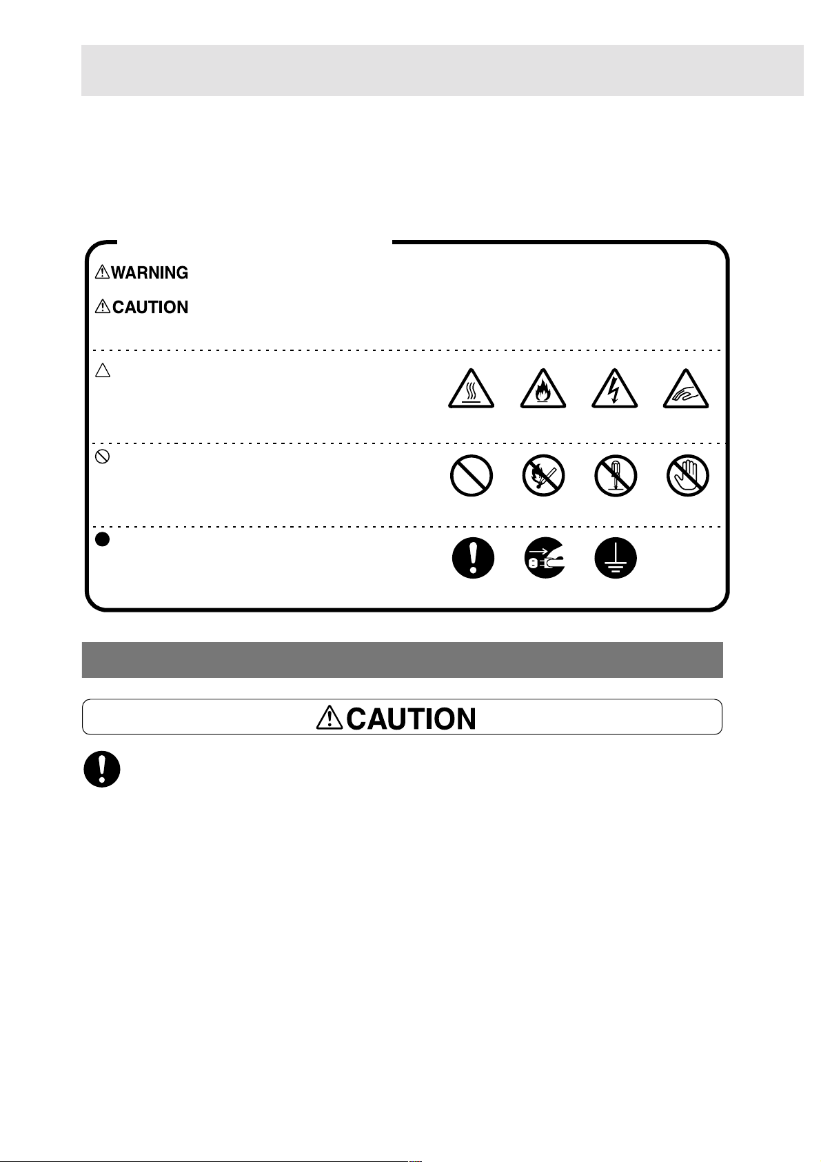
Conventions and symbols
is used to alert operators to an operating procedure, practice or conditi on that, if
not strictly observed, can result in severe injury or loss of life.
is used to alert operators to an operating procedure, practice or conditi on that, if
not strictly observ ed, might result in safety hazards to personnel or damage to
the equipment.
This symbol is used to alert operators to a specific
operating procedure that requires close attention.
Read and follow instructions carefully to ensure the
task is accomplished safely.
This symbol is used to alert operators to a specific
operating procedure that must not be performed.
Read and follow instructions carefully.
This symbol is used to alert operators to a specific
operating procedure that should be emphasised for
operating safety. Read and follow instructions
carefully.
Heated
surface
Prohibited!
Instructions Unplug Ground/Earth
Flammable
No fire
Electric
shock
Do not
tear dowm
Pinched
fingers
Do not
touch
Precaution for power and earth connection
When connecting interface cable, make sure that the power of the main frame and host
device is switched off to prevent the possibility of electricity shock.
viii
Page 11

Precaution for switching off the power
● When switching off the power for this machine with fax functions, check that the Document
In Memory indicator light on the main frame control panel is off. If the power is switched off
while the light is on, document data spooled in the memory will be erased.
●
After being charged for 45 hours, this machine is able to keep the contents in memory for three
hours.
●
If the Document In Memory indicator light is lit, check if there is any "Received document". If yes,
follow the instruction on display and output it. Otherwise, output the list of stored document and
check the contents.
● When the power is switched off, print data remaining in the printer kit and information
spooled in the memory of the printer kit will be erased.
Also, Secure Print/Sample Print data saved in the Hard Disk will remain but data that has
not been saved completely will be deleted.
Before switching off the power during normal operation, check that the message "Ready to
print" is shown on the display of the cont rol panel.
●
The memory used by the printer belongs to the printer kit, which is different from thos e used b y the
copier and fax functions. However, when the power is switched off, data will be erased from the
memory.
ix
Page 12

This page is intentionally left blank.
Page 13

12
Overview of the Printer
1.1 Getting Ready to Print .....................................................................2
1.2 Special Features of the Printer........................................................ 4
1.3 Main Components and Their Functions...........................................5
Page 14
Overview of the Printer
1
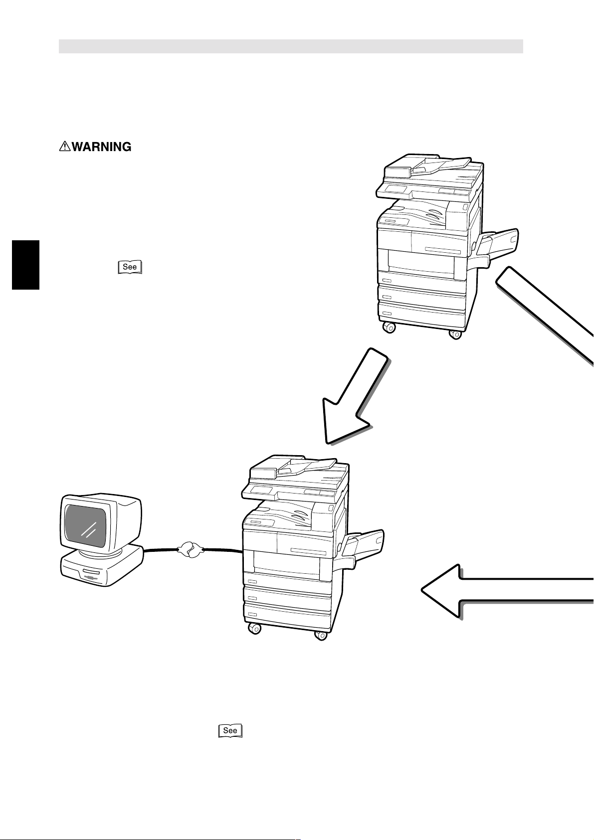
Getting Ready to Print
1.1
This section explains the procedure for setting up the printer. The flow of operations is as follows:
Check that the printer is switched off before handling it to prevent electric
shock.
Connect the cable and allocate memory.
"Chapter 2 Setting Up"
Parallel
When connecting to
the host device
directly
Carry out the necessary installation
and setting to th e computer.
The printer control panel also needs to
be set.
2
"Chapter 4 Installing/Configuring the Printer Drivers"
Page 15
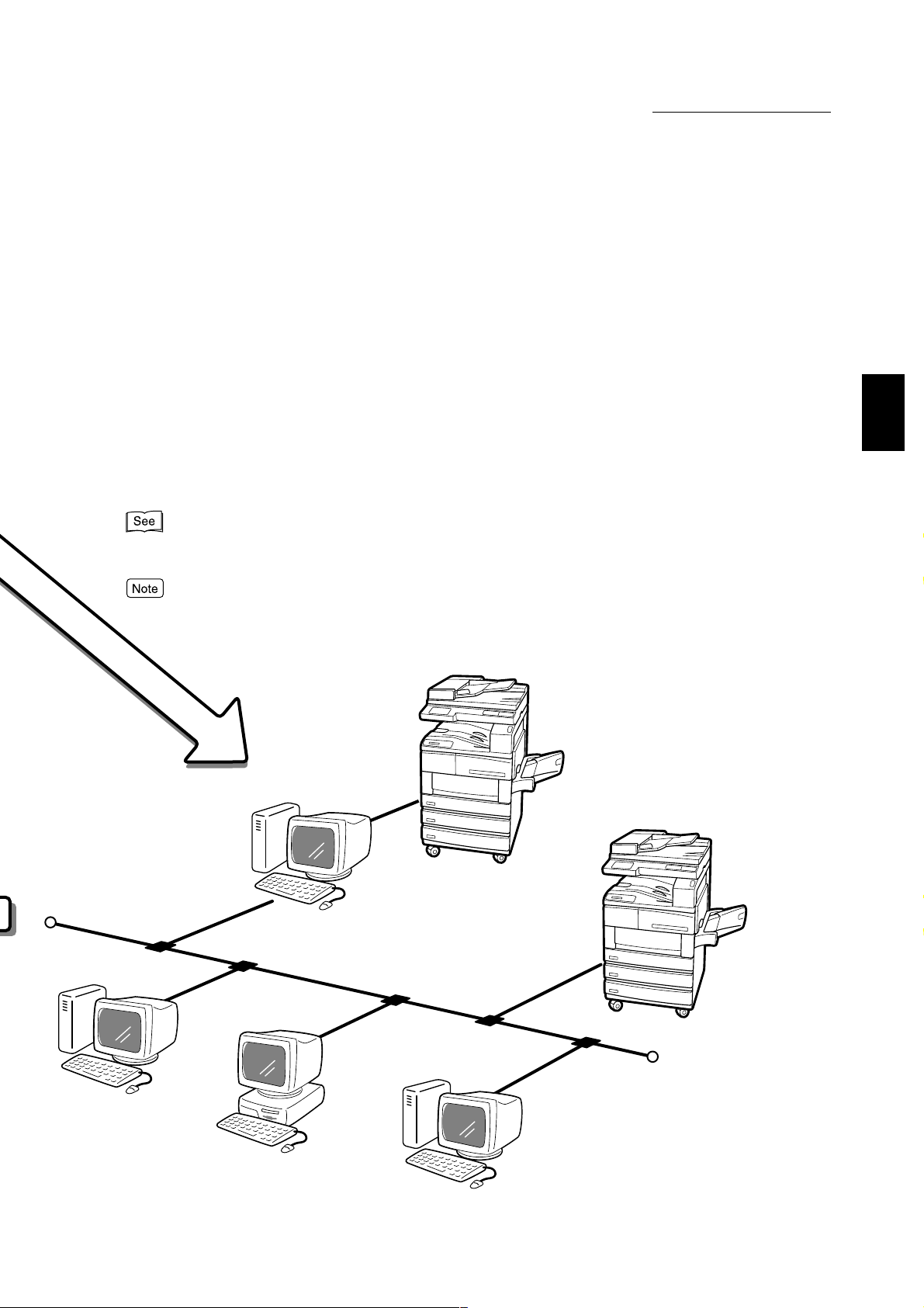
When the printer is used via a network, it is necessary to make settings on
the different types of servers and the printer control panel.
1.1 Getting Ready to Print
Overview of the Printer
1
Network Print Environment User Guide (Network.pdf) in the PCL Driver/Network Utility
(Windows
It is suggested that the memory be increased.
When connecting to network
) CD-ROM regarding these settings.
3
Page 16

Special Features of the
Overview of the Printer
1
1.2
Printer
This printer kit can be used as a network-compatible printer that can be connected directly to the
network.
It can be installed w ith multi-emulation.
The special features of the printer are as follows:
●
It is installed with PCL emulation. PostScript emulation is an optional feature.
●
Printing can be specified without taking into consideration the printer language as there is an
automatic printer language detection feature (applicable only when more than one emulation is
installed).
●
High quality printing can be achieved with its 400/600 dpi laser-style resolution.
Also, it comes with an image-enhancement feature which can increase resolution and produce
smooth printing witho ut any notches (equivalent to 2,400 dpi).
●
Besides the par allel and USB interfaces, it can be used in network (multi-protocol) environment
through the inst allation of interfa c e card for Ethernet or Token Ring. Token Ring is an optional
feature.
●
All the interfaces installed can receive data at the same time, except Ethernet and Token Ring
which are mutually exclusive.
●
Double-sided printing can be done by in stalling a duplex modul e.
●
Multiple-copies sorting can be achieved through the electronic sorting feature (when installing the
hard disk). Also, there is no need to rear r an ge pa ges as pag es ca n be out put wit h the prin te d si de
facing up without interrupting the page order.
●
DPI is the abbreviation of Dot Per Inch and is the unit that indicates the number of dots that can be
printed within a one-inch area. It is used as a unit indicating resolution.
●
Protocol is the essential communcation regulation for carrying out data transmission.
4
Page 17
Main Components and
1.3
Their Functions
This section de scribes the names o f the v arious p arts of the p rinter k it. For other parts, see "1. 1 Mai n
Components and Their Functions" of the User Guide (Copier).
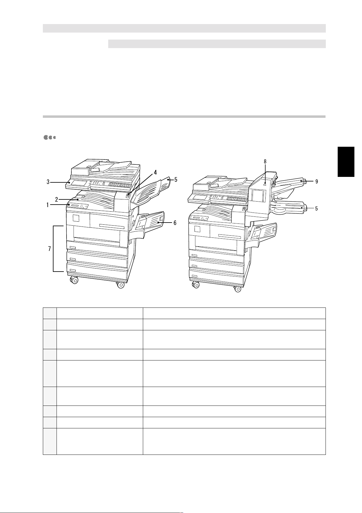
1.3.1 Parts of the printer kit
Front view
Overview of the Printer
1
1 Printer control panel For use of printer functions.
2 Center output tray For outputting printed copies, facing down.
3 Control panel For use of copier functions. When necessary, it will also
indicate that the machine is being used for printer functions.
4 Switch For switching machine on/off.
5 Side output tray* For outputting printed copies, facing up. When the optional
finisher is installed, the lower tray of the finisher will become
the side output tray.
6 Bypass tra y* For loadi ng p ape r so urce tha t c annot be lo ad ed i n pap er tr ays,
like postcard or transparency.
7 Pape r trays* For loading paper. Tray 4 is an optional kit.
8 Pause/Resume button For retrieving paper output to the finisher.
9 Finisher tray (upper)* For outputting printed copies when the finisher is installed.
Documents output here can be stapled. Finisher is an optional
kit.
* optional kit but may be installed for certain models
5
Page 18
Overview of the Printer
1
1.3 Main Components and Their Functions
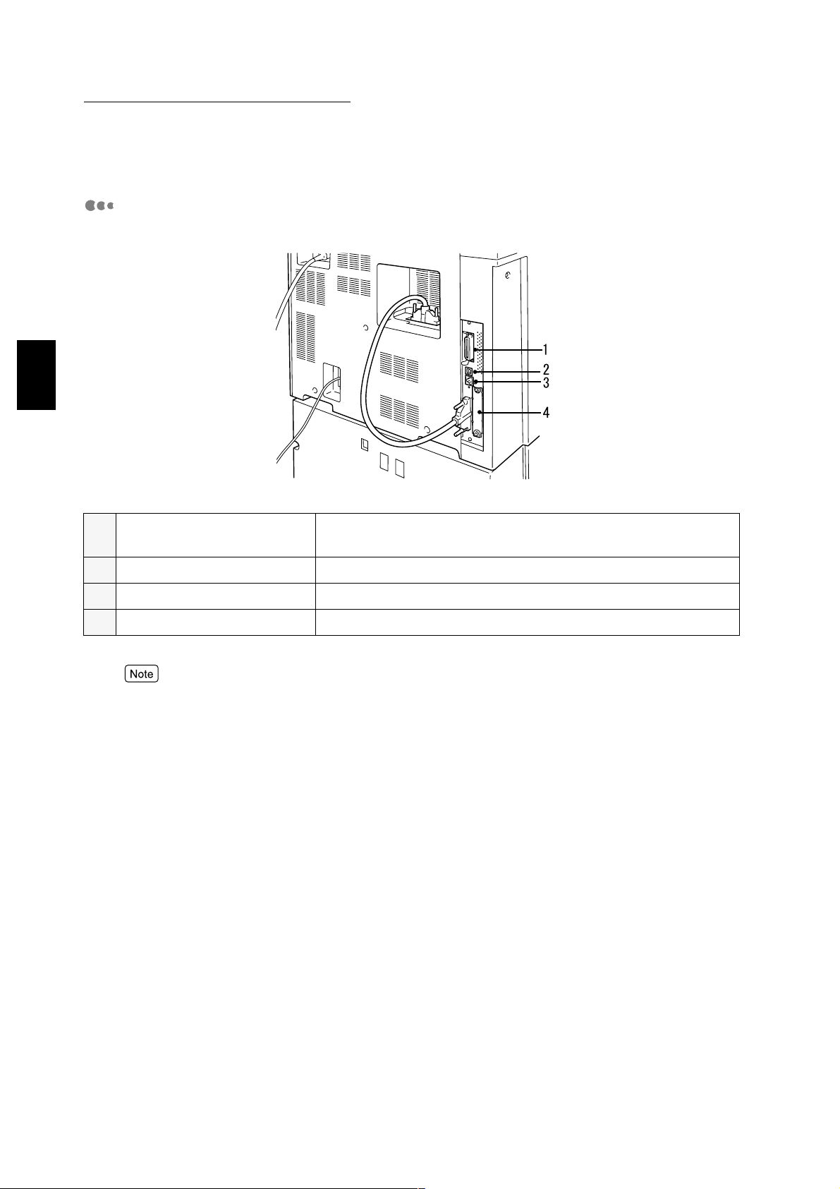
Back view
1 Parallel interface connector For connecting this printer t o a computer by a cen tronics/IEEE
1284-compliant interface cable.
2 USB interface connector For connecting this printer to a computer by an USB cable.
3 Ethernet interface connector For conn ecting this printer by an Ethernet interface cable.
4 Slot fo r Token R ing interface For attaching an optional interface board (for Token Ri ng).
To install Token Ring, you will need an Token Ring Installation Kit besides the interface board (for Token
Ring). Contact our Customer Support Center for installation of the kit by our customer engineers.
6
Page 19
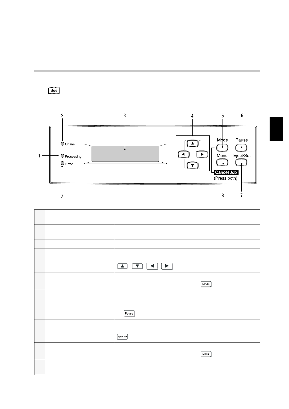
1.3.2 Printer control panel
The different parts of the printer control panel are as follows:
"1.3.3 Display message" for details on the messages of the display.
1.3 Main Components and Their Functions
Overview of the Printer
1
1 Processing indicat or When the light is on, indicates that this printer is processing
print instructions.
2 Online indicator When the light is on , indicates that this printer is ready to
receive data from the computer.
3 Display Shows settings, printer status, messages etc.
4 The up, down, right, left
buttons
5 Mode button Press to enter to the mode menu.
6 Pause button Press to enter to the pause state. When in the pause state, no
7 Eject/Set button Press to set the can didate value of the menu. Also used to
8 Menu button Press to navigate to the common menu.
Press to navigate the menu, menu item, item and candidate
value. In this manual, these four buttons will be displayed as
, , , .
In this manual, it will be displayed as .
data can be received and print instruction processed. Press
again to e xi t th e paus e state . In this manual , it will be d isplayed
as .
print reports and lists. In t his manual, it will be displayed as
.
In this manual, it will be displayed as .
9 Error indicator When the light is on, indicates that there is a machine
breakdown.
7
Page 20
Overview of the Printer
1
1.3 Main Components and Their Functions
1.3.3 Display message
The displa y sho ws messages i ndicati ng the printe r and sett ings sta tus , and which may include
the following screens.
Depending on the optional kits installed, printer settings, and printer model, some messages may not be
displayed.
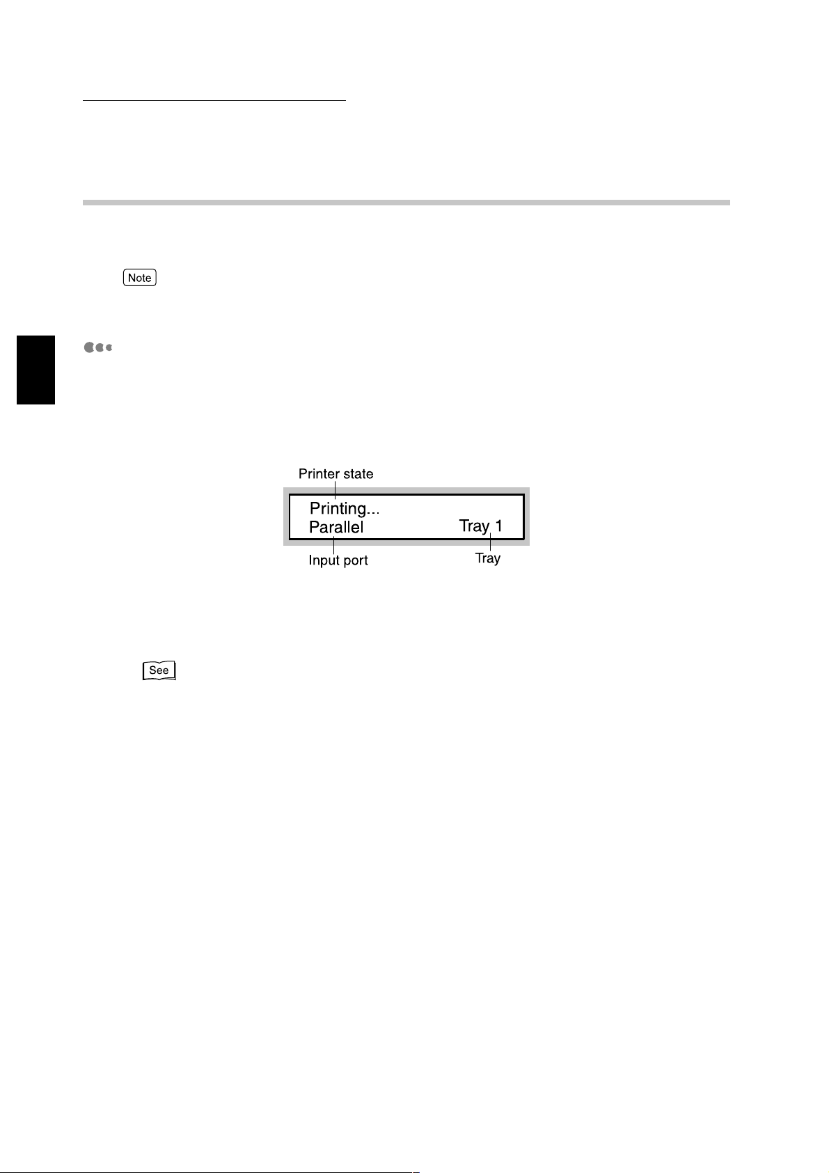
Print screen
While printing or waiting for data, the display will show the print screen which indicates the
printer status as well as the ongoing data processing.
As an example, the following message will be shown on the display when data has been
received from the parallel port and is to be printed on paper from tray 1:
Printer state
Indicates the st ate of the printer.
Messages include " Please wait", "Ready to print", "Printing", "Canceling" and "Dat a wait".
"7.3 Messages" regarding the messages.
Input port
Indicates the input port that is receiving the data.
Messages include "Parallel", "IPP", "SMB", "EtherTalk", "LPD", "NetWare", "USB",
"Port9100".
Tray
Indicates the paper tray for printing.
Messages include "Tray 1", "Tray 2", "Tray 3", "Tray 4", "Bypass".
8
Page 21
1.3 Main Components and Their Functions
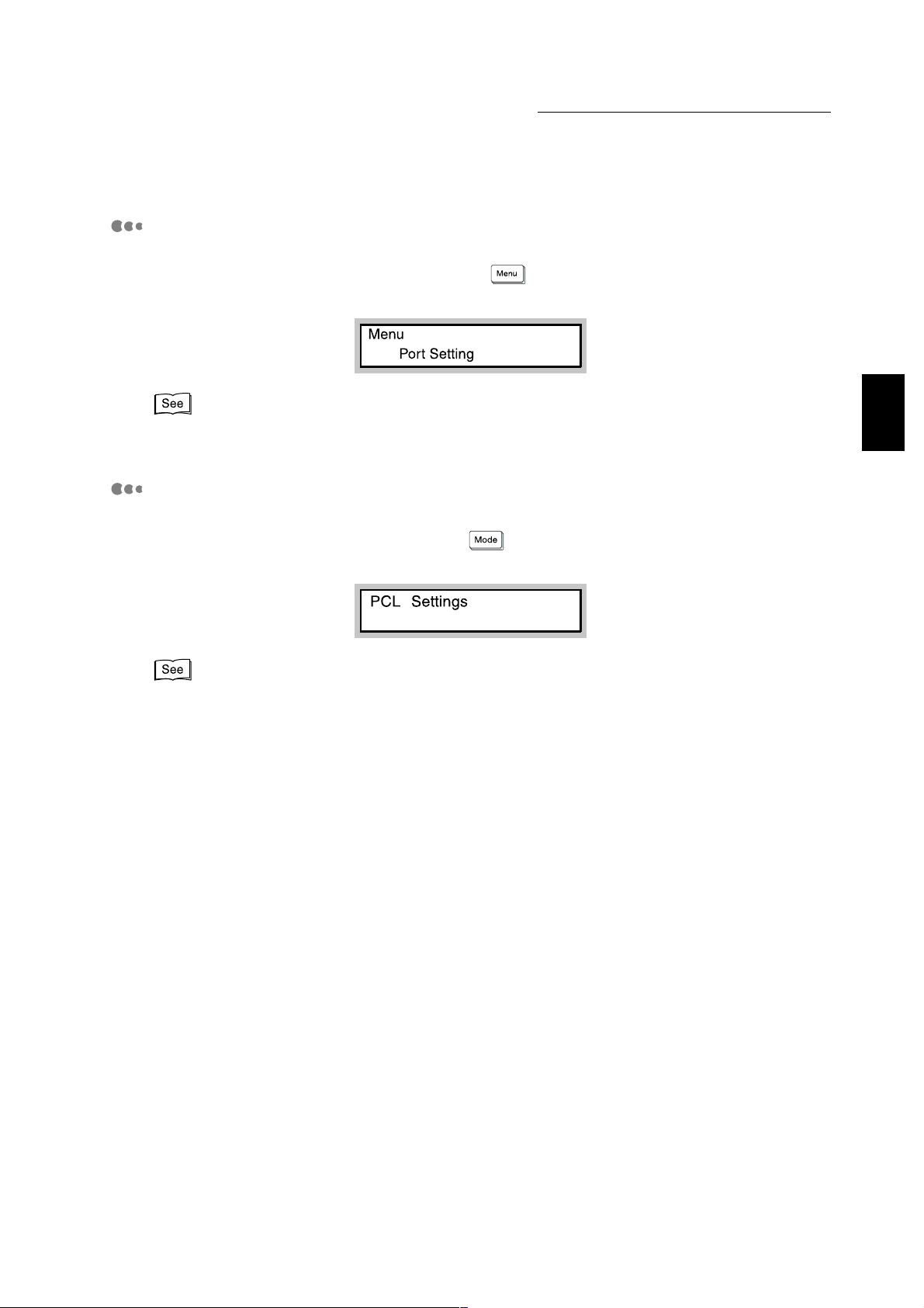
Common menu screen
The screen to set items common to all print modes.
To dis p lay the comm on menu screen, press .
As an example, the screen to set Port Setting is di s pl ayed as follows:
Overview of the Printer
"5.3 Common Menu Items" for details on the Common menu screen.
Mode menu screen
The screen to fix setting for emulati on processing.
To display the mode menu screen, press .
As an example, the screen to set PCL Settings is displayed as follows:
"5.2 Mode Menu Items" for details on the mode menu screen.
1
9
Page 22
1.3 Main Components and Their Functions
Overview of the Printer
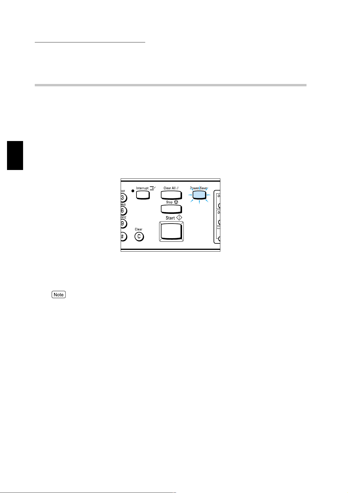
1.3.4 Power Saver Mode
This machine has a power saver feature that reduces the power consumption when the
machine is switched on and left unused for a certain duration. There are three modes in this
power saver feature.
●
Standby mode: The motor is left idle.
●
Low power mode: The temperature of the heater area is kept low and the motor is left idle.
●
Sleep mode: The main power is switched off (the mode which can save the most power).
1
When the machine is in Low power mode or Sleep mode, the touch panel display will be off
and the
When print data is received from the computer, the machine will automatically exit the power
saver mode and start processing printing.
You can exit the power saver mode by pressing the illuminated
To use the printer control panel during power saver mode, exit the mode first by pressing
Power Saver
lights up .
Power Saver
.
Power Saver
.
10
Page 23

2
Setting Up
2.1 Setting Printer Environments......................................................... 12
2.2 Connecting Cable................... ... ....................................................18
2.3 Using Quick Setup Menu........ ... ... ... .............................................. 23
2.4 Flow of Setting Different Printer Environments.............................. 26
2.5 Setting IP Address......................................................................... 27
2.6 Setting Port....................................................................................32
2.7 Other Printer Settings................ ... ... ... ......................... .................. 36
2.8 Memory Allocation......................................................................... 38
Page 24
Setting Printer
Setting Up
2
2.1
Environments
This section explains the different printer environments that can be set up for the printer.
When connected to a co mputer directly, the printer can be used as a local printer.
When connected to a network, the printer can be used as a network printer. As this printer supports
multi-protocol, it can be shared among users fro m different network environments.
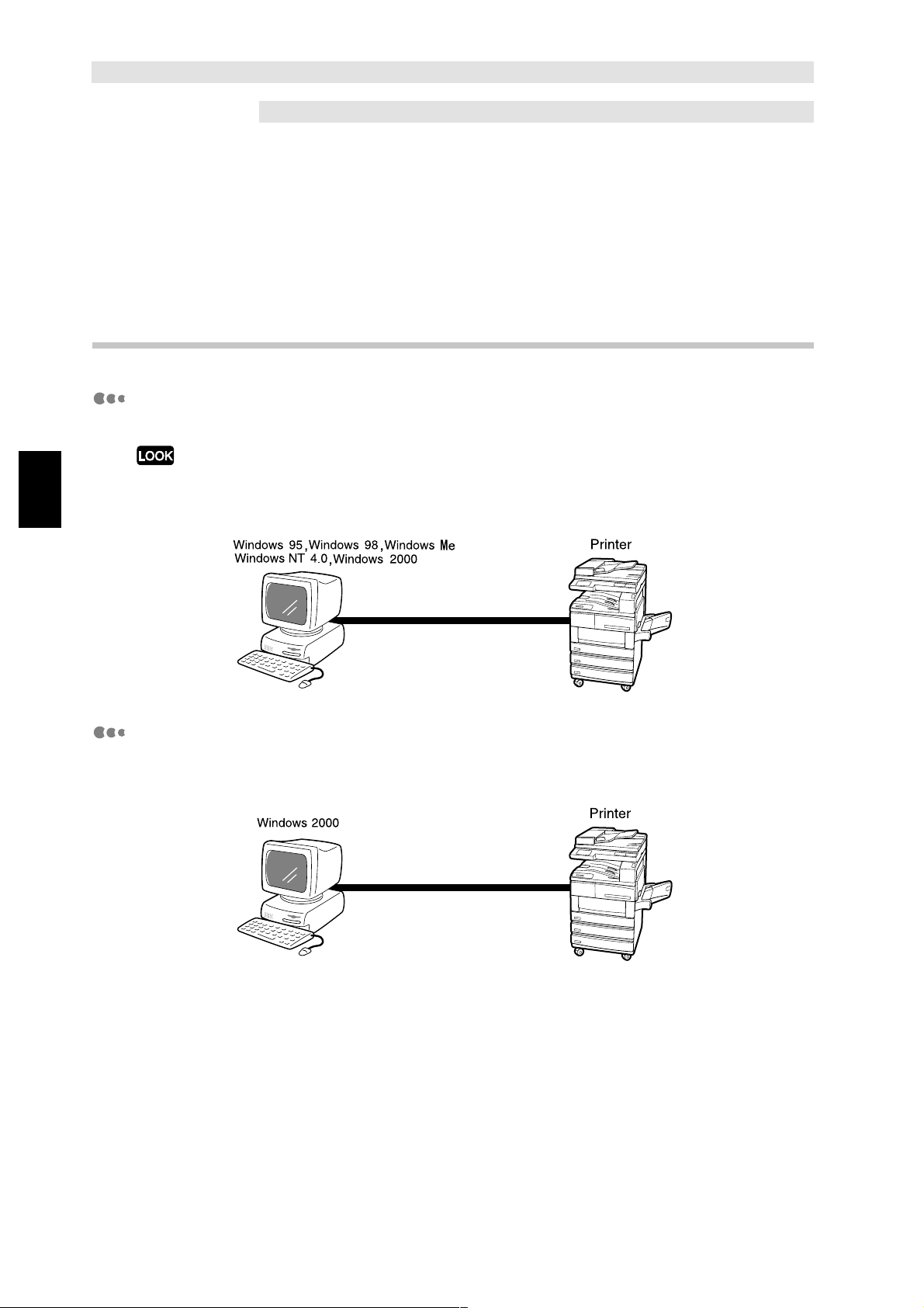
2.1.1 As a local printer
Using parallel interface
Connects the printe r to a computer by parallel interface for printing.
Use only the parallel interface cable provided by our company, as an optional product. Using parallel
interface cable from other company might lead to electric wave obstruction.
Using USB interface
Connects the printer to a computer by USB cable for printing.
12
Page 25
2.1 Setting Printer Environments
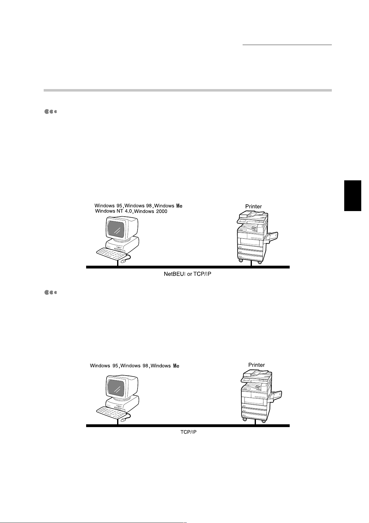
2.1.2 As a network printer (Ethernet interface)
Windows Network (SMB)
Server Message Block (SMB) is a protocol for sharing file or printer on Windows 95,
Windows
or settings can be sent directly to a printer on the same network (Ethernet interface) without
going through the server.
As this printer supports SMB, y ou can print b y ju st acti v ati ng the SMB port and registe ring the
printer on the network on each of the Windows 95, Windows 98, Windows Me, Windows NT
4.0 and Windows 2000 operating system (OS).
You can use NetBEUI and TCP/IP as the transport protocol for SMB.
98, Windows Me, Windows NT 4.0, and Windo ws 2000. Using SMB , print data
Setting Up
2
TCP/IP Direct Print Utility (Windows 95, Windows 98, Windows Me)
TCP/IP Direct Print Utility is a software developed by our company to allow print data to be
sent directl y from a Wi ndows 95, Wind ows 98 , Windo ws Me com puter to a printer on the sa me
network (Ethernet inte r face) without going thro ugh the serv er. As this printer su ppo rts TCP/IP
(LPD) protocol , th e p rint dat a can be s ent d ir ec tly a nd p rint ed fr om th e W indows 95, Windows
98, Windows Me computer when using this software. You will need to set the IP address on
the printer and the Windows 95, Windows 98, Windows Me computer.
13
Page 26
Setting Up
2
2.1 Setting Printer Environments
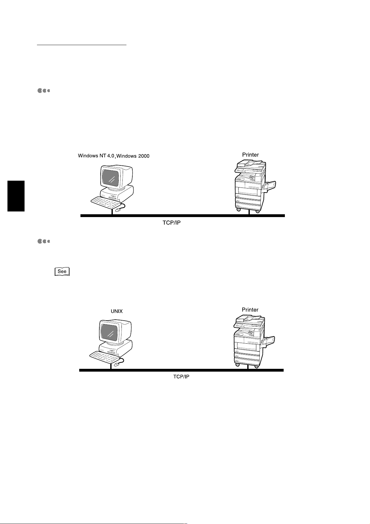
TCP/IP (Windows NT 4.0, Windows 2000)
As this printer supports TCP/IP protocol, print data can be sent directly from a Windows NT
4.0, Windo ws 2000 compu ter f or printing, no t only u sing SMB b ut LP R as w ell. You will ne ed to
set the IP address on the printer and the Windows NT 4.0, Windows 2000 computer.
And once the printer registered on the Windows NT 4.0, Windows 2000 computer is shared,
you can also print from Windows 95, Windows 98, Windows Me com puter through this printer.
TCP/IP (UNIX)
As this printer supports TCP/IP protocol, you can print from a UNIX machine. You will need to
set the IP address on the printer and the UNIX machine.
Network Print Environment User Guide (Network.pdf) in the PCL Driver/Network Utility (Windows) CDROM for details on printing from the UNIX machine.
14
Page 27
2.1 Setting Printer Environments
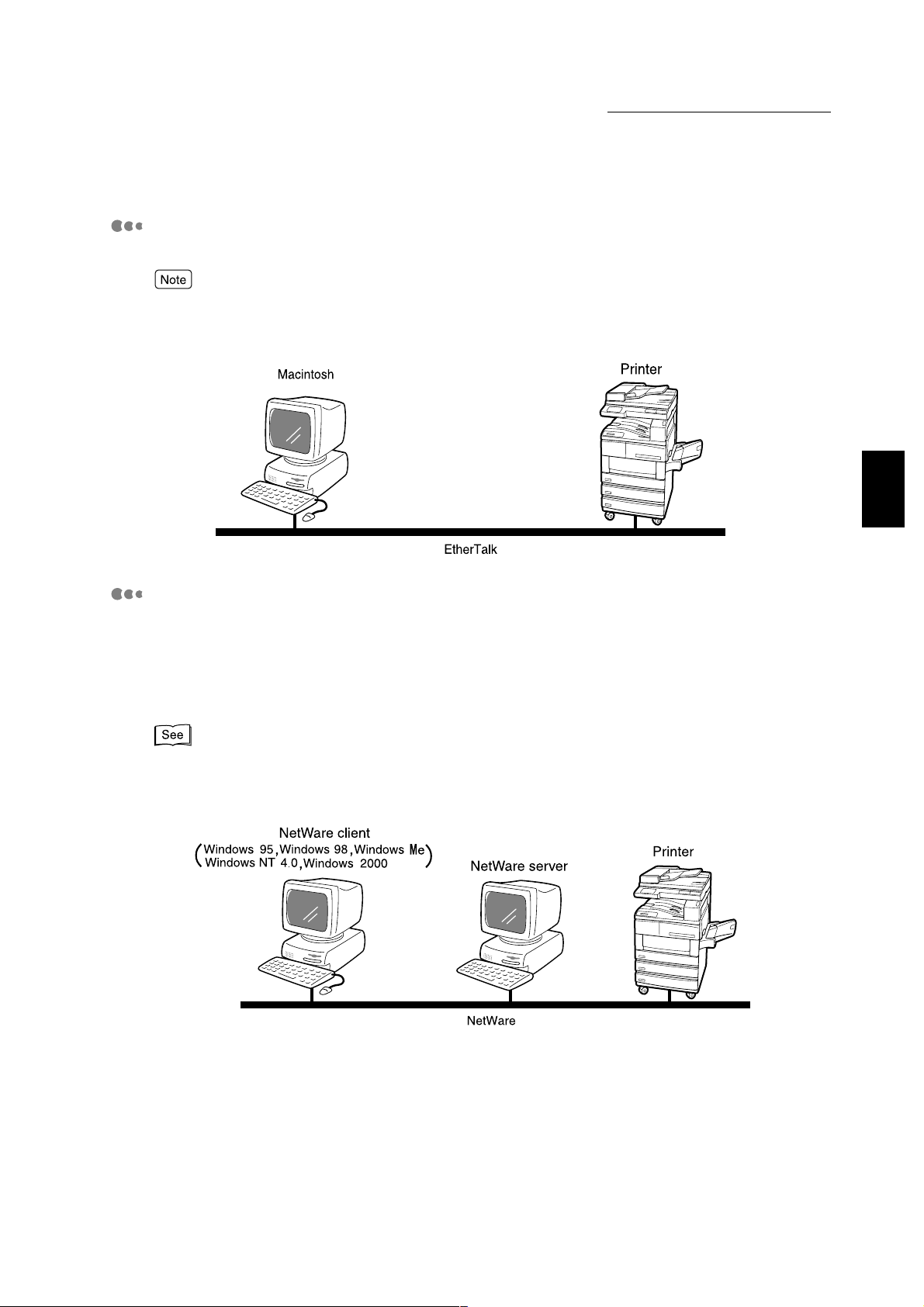
AppleTalk
As the printer supports AppleTalk protocol, you can print from a Macintosh using EtherTalk.
You will need the optional PostScript Kit for using EtherTalk to print. Refer to the manuals bundled with
the PostScri pt Kit for details on using it.
Setting Up
2
NetWare
As a network OS, th is printer supp orts Novell NetWare (version 3.12, 3.2, 4.11, 4. 2, 5, 5. 1) as
well as the prin t serv er (PS erv er) mo de onl y usi ng bi ndery and NDS (version 4.11 and ab o ve).
In the PServer mode, the printer will be the the print server and will print out jobs in the print
queue. This printer uses one user licence of the file server.
You can use IPX/SPX and TCP/IP as the protocol for NetWare.
Network Print Environment User Guide (Network.pdf) in the PCL Driver/Network Utility (Windows) CDROM for details on using NetWare for printing.
15
Page 28
Setting Up
2
2.1 Setting Printer Environments
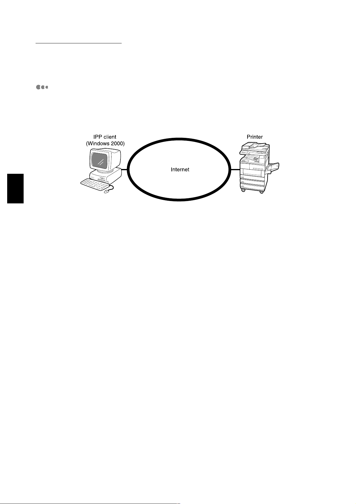
Internet printing
This printer supports Internet Printing Protocol (IPP). As Wind ows 2000 is installed with the
client software needed to output to IPP printer, you can spec ify the printer to support IPP
using the Add Printer Wi zard . Us ing I P P, you can print to a r emot e printer th roug h t he i nternet
or intranet.
16
Page 29
2.1 Setting Printer Environments
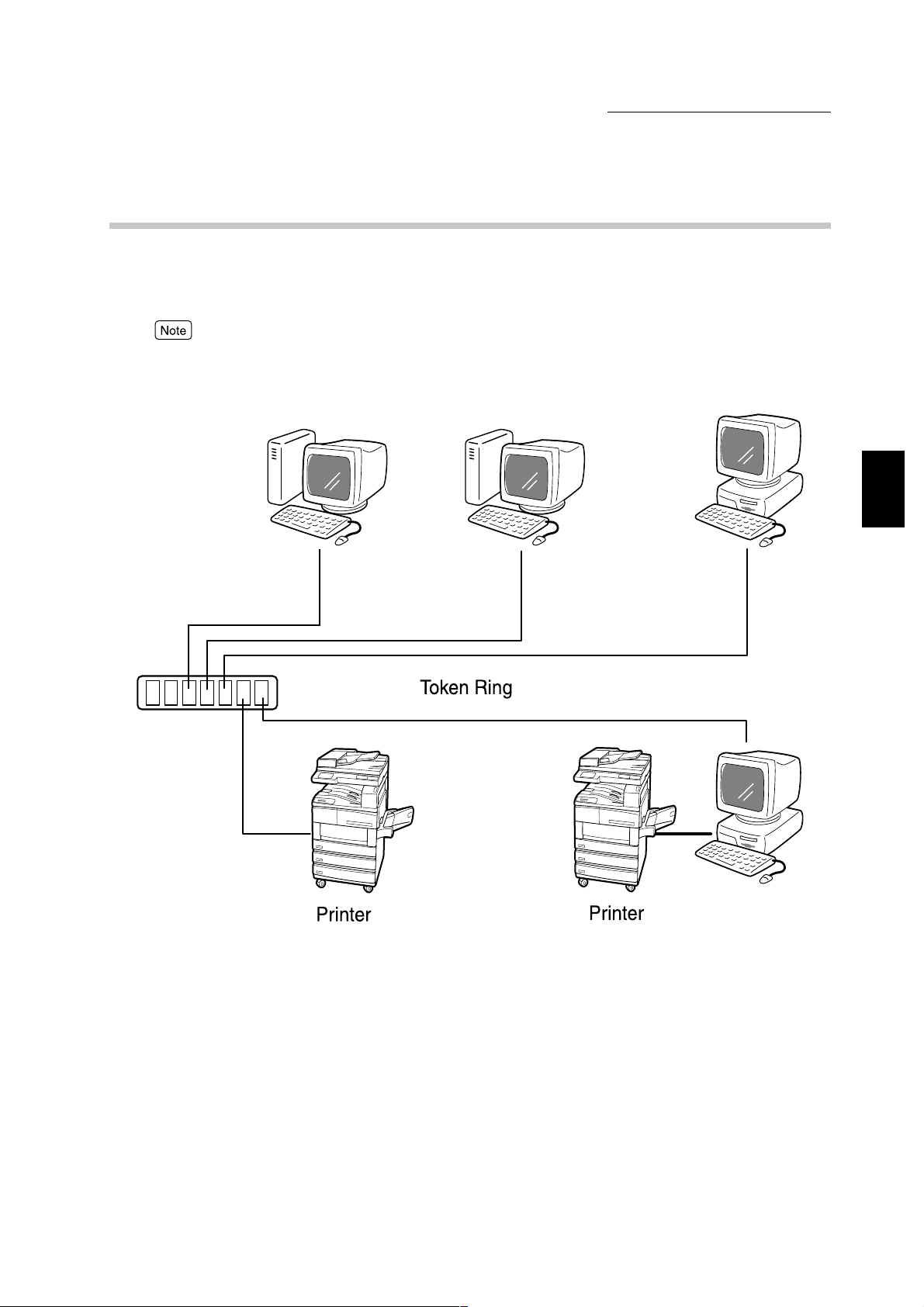
2.1.3 As a network printer (Token Ring interface)
This printer supports Token Ring. When insta lled with the optional interface board for Token
Ring, y ou can us e the print er i n a netw ork en vi ronme nt wit h NetWare or TCP/IP e xi stin g alon e
or together.
Whe the interface board for Token Ring is installed, the Ethernet interface cannot be used. Also, the
items that can be set are also different. Refer to "2.2.4 Connecting by Token Ring interface" for details.
Setting Up
2
17
Page 30
2.2
This section describ es connecting by cable, to the interfac e of the environment to be used.
Remember to switch off the power supply during installation to prevent electric shock.
You cannot use the optional Token Ring interface together with Ethernet interface.
Setting Up
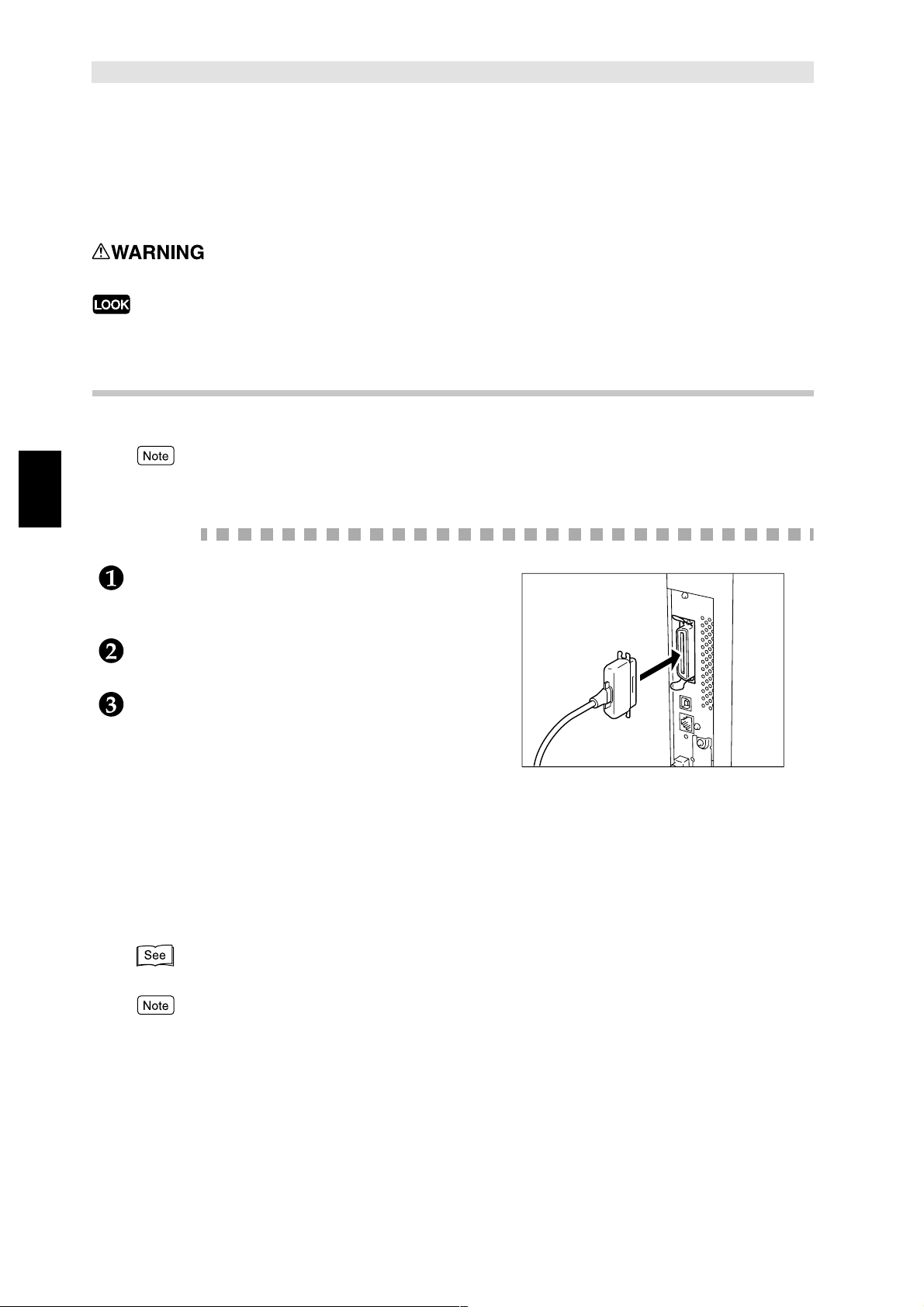
2.2.1 Connecting by parallel interface
Connecting Cable
The following procedure explains how to connect by the parallel interface.
2
To connect by the parallel interf ace, y ou will need the parallel interfac e cable provided b y our company as
an optional product. For details, consult our Customer Support Center.
Procedure
Insert the interface cable connector to the
parallel interface connector and secure it by the
wire clips on both sides.
Connect the other end of the interface ca ble
connector to the co m p uter.
Switch on the pr in te r.
If necessary, set the following items on the printer control panel (Network/Port > Parallel):
●
Print Mode
●
PJL
●
Adobe Protocol
●
Auto Eject Time
●
Bi-directional
(Factory setting: Auto)
(Factory setting: Enable)
(Factory setting: Normal)
(Factory setting: 30 Secs)
(Factory setting: Enable)
18
"5.3 Common Menu Items" for details on the individual item and the setting method.
For normal use, there is no need to change the factory settings of all the items.
Page 31

2.2.2 Connecting by USB interface
The following procedure explains how to connect by the USB interface.
USB is supported by Windows 2000 only.
2.2 Connecting Cable
Insert the USB cable connector to the USB
interface connector.
Connect the othe r en d of the in te rface cable
connector to the computer.
Switch on the printer.
On the printer co nt rol pan e l, set th e USB Port to
Enable.
Proceed by following the procedure below:
Setting Up
2
19
Page 32

Setting Up
2
2.2 Connecting Cable
If necessary, set the following items on the printer control panel (Netwo rk/Port > USB):
●
Print Mode
●
PJL
●
Adobe Protocol
●
Auto Eject Time
"5.3 Common Menu Items" for details on the individual item and the setting method.
For normal use, there is no need to change the factory settings of all the items.
(Factory setting: Auto)
(Factory setting: Enable)
(Factory setting: Normal)
(Factory setting: 30 Secs)
20
Page 33

2.2.3 Connecting by Ethernet interface
The Ethernet interface supports the following two types of environment:
●
100BASE-TX
●
10BASE-T
2.2 Connecting Cable
The factory setting of Ethernet is set as Auto, enabling automatic switching to 100BASE-TX or
10BASE-T.
The fol lowing procedure explains how to connect by the Ethernet interface:
Procedure
Insert the Ethernet interface cable connector to
the interface connector.
Use only interface cable suitable for the network
connection in use.
Switch on the printer.
When you want to fix the transmission speed for 10BASE-T or 100BASE-TX connector or
change the printer s etting according to the environment in use while connected to 10BASE-T/
100BASE-TX connector, refer to "5.3 Common Menu Items".
Setting Up
2
21
Page 34

Setting Up
2
2.2 Connecting Cable
2.2.4 Connecting by Token Ring interface
The Token Ring interface supports the follo wing two types of environment:
●
UTP
●
STP
The following procedure explains how to connect by the Token Ring interface.
When the Token Ring interface board has been installed, the Ethernet interface cannot be used. And as
a result, the Ethernet board cannot be used too.
●
To set up Token Ring, you will need the Token Ring Installation Kit besides the Token Ring interface
board. The Token Ring Installation Kit will be installed by our customer engineer. Contact our
Customer Support Center for details.
●
When the Token Ring interface port is installed, the MAC address will be changed.
●
When using gateway in Token Ring environment, set Source Routing to On.
Procedure
Insert the Token Ring interface cable connector
to the interface connector.
Use only interface cable suitable for the network
connection in use.
Do not connect the interface cable to the two Token
Ring interface port connectors as this will cause poor
transmission or breakdown.
Switch on the pr in te r.
If necessary, set the following items on the
printer control panel (Network/Port>):
●
IPX/SPX FrameType
●
(Token Ring>) Transmit Rate
●
(Token Ring>) Max Packet Size
●
(Token Ring>) Source Routing
"5.3 Common Menu Items" for details on the items and the setting method.
(Factory setting: Auto)
(Factory setting: Auto)
(Factory setting: 1500B)
(Factory setting: Off)
For normal use, there is no need to change the factory settings of all the items.
22
Page 35

Using Quick Setup Menu
2.3
When setting up the printer environment, you can use the Quick Setup menu to set the basic
necessary items all at once.
Quick Setup menu items
The following menu items can be set by the Quick Setu p me nu. Set each item by answering
the questions displayed on the printer control panel.
Item Remarks
Sets whether you want an auto
print of the Job History Report.
Sets system clock. The system cloc k displays the date and time in
Sets the network port, protocol
and spool setting.
Sets whether to use Internet
Service.
The Job History Report includes information on
the latest 50 print jobs. Sets whether you want to
print the Job History automatically for every 50
print jobs rea c he d.
the following formats:
• YYYY.MM.DD (year.month.date)
(for years between 2000-2099 only)
• HH:MM (hour:minute).
The date and time set here will be printed in lists
and reports.
You can use the Quick Setup menu to define
settings for multiple ports all at once:
• SM B, LPD, IPP, NetWare, EtherTalk (optional)
Sets the port, protocol and spool setting to be
used for the network environmen t.
• SNMP
Sets this when us ing softw are li ke f or man aging
multiple printe rs rem o te ly.
The CentreWare Internet Services can be used ,
through a web browser, to display the printer/ job
status and cha ng e the printer settings.
Setting Up
2
Sets whether to use Dynamic Ho st
Configuration Protocol (DHCP),
BOOTP or RARP as well as to set
the IP address.
(To be set only when using TCP/
IP)
You can also specify settings for the individual items without using the Quick Setup Menu. For items that
cannot be set using the Quick Setup Menu or details on setting individual items, refer to "2.4 Flow of
Setting Different Printer Environments" and "5.3 Common Menu Items".
Sets whether to obtain automatically essential
information for using TCP/IP (e.g. IP address,
subnet mask, gateway address) from the DHCP
server, BOOTP or RARP.
Enter the IP address manually if the DHCP
server, BOOTP or RARP is not used.
23
Page 36

Setting Up
2
2.3 Using Quick Setup Menu
Procedure for setting the Quick Setup Menu
Follow the procedure below to set essential settings using the printer control panel.
When using the Quick Setup Menu to change settings, select Y for Save Settings to save settings and
reboot before printing the Printer Settings List.
●
During setting up, the settings will not be valid if your press
●
R: Reboot; Y: Yes; N: No.
.
24
Page 37

2.3 Using Quick Setup Menu
Setting Up
2
25
Page 38

Flow of Setting Different
Setting Up
2
2.4
Printer Environments
This section explains the flow of setting the printer environmen t for the different environment in use.
Check the necessary settings for the respective printer environments as your proceed by following
the flow chart. When using EtherTalk, refer to the manual bundled with the PostScript Kit.
*1 You can install the printer driver from the attached CD-ROM or download it automatically.
Refer to the Network Print Environment User Guide (Network.pdf) in the PCL Driver/Network Utility
(Windows
*2 For details on the procedure to install the printer driver when using IPP, refer to the above-mentioned
Network.pdf file.
*3 For details on the procedure to set up the environment for using NetWare, refer to the above-mentioned
Network.pdf file.
*4 For details on the procedure to change the host name and workgroup name, refer to the above-
mentioned Network.pdf file.
26
) CD-ROM.
Page 39

Setting IP Address
2.5
This section explains how to set the IP address.
Depending on the net work environment, you ma y need to se t t he subnet mask and gateway addres s.
If your network has a Dynamic Host Configuration Protocol (DHCP), BOOTP or RARP environment,
the printer can obtain t hese items automatically from each of the server.
By the factory setting, these items are obtained automatically from the DHCP server.
●
Use the DHCP server together with the Windows Internet Name Service (WINS) server at the same time.
When using the WINS server , set setti ngs if necessary, by selecting the f ollo wing on the printer control panel:
Network/Port
●
When using the BOOTP or RARP server, select the following on the printer control panel:
Network/Port
Check with your system administrator if you have any queries on the BOOTP or RARP environment.
"5.3 Common Menu Items" for details on each of these items and the way to set them.
, followed by
, followed by
WINS Server
TCP/IP Settings, Get IP Address
, and then the various items.
, and then
BOOTP
or
RARP
.
2.5.1 Flow of setting
When the IP address is obtained automatically f rom the DHCP, BOOTP or RARP server, you
do not need to follow the procedure in this section to set the IP address.
When you need to set the IP address manually using the printer control panel, refer to "2.5.2
Setting Address".
When you are unsure whether you have a DHCP server, follow the procedure below to check.
If you do not have a DHCP server, set the IP address by referring to "2.5.2 Setting Address".
Checking DHCP server
Setting Up
2
Check with your system administrator if you have any queries on DHCP environment.
27
Page 40

Setting Up
2
2.5 Setting IP Address
Outputting Printer Settings List
Procedure
Print out the Printer Settings List by referring to "5.4 Outputting Reports/Lists".
Check the following items under Communication Settings on the Printer Settings list:
●
TCP/IP: IP Address
●
TCP/IP:Subnet Mask
●
TCP/IP: Gateway Address
●
WINS Server: Primary Server IP Address
●
WINS Server: Secondary Server IP Address
Refer to the following se ction on how to check the Printer Settings List.
Checking Printer Settings List
●
When the addresses in TCP/IP and WINS are not obtained:
There is no DHCP server and WINS server.
Set the IP address by referring to "2.5.2 Se tti ng Add re ss" .
●
When the address in TCP/IP is obtained but not in WINS:
There is no WINS server. Do not use the DHCP environment as the printer may not be
usable due to a change in the IP address allocated to the machine.
Set the IP address manua ll y by referring to "2.5.2 Sett in g Ad dre s s ".
●
When the addresses in both TCP /IP and WINS are obtained:
The DHCP server and WINS server are in operation. It is recommended to use the DHCP
environment. When the DHCP environment is used, the printer IP address is set by the
DHCP server. The name, "FX-xxxxxx" listed in Host Name of SMB under Communic ation
Settings in the Printer Settings List is regis tered in the WINS server.
28
Page 41

2.5 Setting IP Address
2.5.2 Setting Address
The fol lowing procedure explains how to set the IP address from the printer control panel.
Depending on the net w ork used , you may need to set the sub net mask and ga t eway address.
Consult your system administrator before setting the essent ial items. Take note that the initial
displa y of the IP address setting might be dif fer ent. If the messa ge initiall y displa yed is " Unable
to get IP Address", proceed from Step after pressing
Setting IP Address
.
Setting Up
2
29
Page 42

Setting Up
2
2.5 Setting IP Address
Setting Subnet Mask and Gateway Address
30
Page 43

2.5 Setting IP Address
Setting Up
2
31
Page 44

Setting Port
2.6
Activate the por t to be used from the printer co n tro l pa nel.
If the settings have already been set to Enable, the proc edure here is not needed. F ollow the
procedure here only if the settings have been set to Disable.
You can als o set th e po rt setting s fro m CentreWare Internet Ser v i ce s. For details, refer to "5.5
CentreWare Internet Services".
Setting Up
2
When using TCP/IP (LPD)
●
(LPD) Port Status (factory setting: Enable)
"2.6.1 Activating port" for details on activating LPD port.
When using internet printing
●
(IPP) Port Status (factory setting: Disable)
"2.6.1 Activating port" for details on activating IPP port.
When using SMB
●
(SMB) Port Status (factory setting: Enable)
●
(SMB) Transport Protocol (factory setting: TCP/IP, NetBEUI)
"2.6.2 Setting the port and transport protocol" for details on setting the SMB port and transport protocol.
When using software for managing printer remotely
●
(SNMP) Port Status (factory setting: Enable)
●
(SNMP) Transport Protocol (factory setting: UDP)
32
"2.6.2 Setting the port and transport protocol" for details on setting the SNMP agent and transport
protocol.
Page 45

2.6 Setting Port
2.6.1 Activating port
As an e xamp le , th e following proce dure explains how to ac ti vate the LPD port (factory setting:
Enable) using the printer control panel.
Foll ow the same procedure if you are activating the IPP port (factory setting: Disable).
Setting Up
2
33
Page 46

Setting Up
2
2.6 Setting Port
2.6.2 Setting the port and transport protocol
As an example, the follo wing procedure expl ains how to activate the SNMP port (factory
setting: Enable) and transport protocol to IPX and/or UDP (factory setting: UDP).
Follow the same procedure if y ou want to activate the SMB port (factory setting: Enable) and
transport protocol (factory setting:TCP/IP, NetBEUI).
34
Page 47

2.6 Setting Port
Setting Up
2
35
Page 48

Setting Up
2
Other Printer Settings
2.7
If necessary, use the printer control panel to define settings for the following items.
However , it is usually not necessary to change the factory settings of these items for normal use.
"5.3 Common Menu Items" for details on each item and the way of setting
When using TCP/IP (LPD)
■Network/Port > LPD
●
Print Mode (factory setting: Auto)
●
PJL (factory sett in g: Enable)
●
Connect Time-Out (factory setting: 16 Secs)
●
TBCP Filter (factory setting: Disable)
●
IP Filter (factory setting: Off)
■Allocate Memory > Buffer Size
●
LPD Spool (factory setting: Off/25 6K)
When using SMB
■Network/Port > SMB
●
Print Mode (factory setting: Auto)
●
PJL (factory sett in g: Enable)
●
TBCP Filter (factory setting: Disable)
■Allocate Memory > Buffer Size
●
SMB Spool (fac tory setting: Of f/256K)
Set the following items by using CentreWare Internet Services or changing the "config.txt" file
of the printer via a Wind ows computer:
●
Workgroup (factory setting: WORKGROUP)
●
Host Name (factory setting: FX-xxxxxx)
[where xxxxxx is the last six digits of the Ethernet address of the printer]
●
Administrator Name (factory setting: admin)
●
Administrator Password (factory setting: admin)
●
Maximum Sessions (factory setting: 5)
●
TBCP Filter (factory setting: Disable)
●
Auto Driver Download (factory setting: Enable)
●
Unicode Suppo rt (factory sett in g: Disable)
●
Auto Master Mode (factor y setting: On)
●
Encryp t Password (factory se tt in g: On )
36
●
"5.5 CentreWare Internet Services" for details on operating CentreWare Internet Services
●
Network Print Environment User Guide (Network.pdf) in the PCL Driver/Network Utility (Windows)
CD-ROM for details on "config.txt" file
Page 49

When using IPP
■Network/Port > IPP
●
Print Mode (factory setting: Auto)
●
PJL (factory setting: Enable)
●
TBCP Filter (factory setting: Disable)
●
Access Control (factory settin g: Disable)
●
DNS (factory setting: Enable)
●
Add Port No. (factory settin g: 80)
●
Connect Time-Out (factory setting: 60 Secs)
■Allocate Memory > Buffer Size
●
IPP Spool (factory setting: Off/256K)
2.7 Other Printer Settings
Setting Up
2
37
Page 50

Setting Up
2
Memory Allocation
2.8
This sections explains how to allocate memory.
2.8.1 Uses
Memory is meant for the following uses:
●
System
●
Receive buffer
●
Page buffer
●
PCL memory
●
PS memory
Besides page b uffer, you can allocate memory using the printer cont rol panel or the
CentreWare Internet Services. The memory allocated will become effective after the power
has been sw itched off and then on again (or after the system has been rebooted).
●
"5.3 Common Menu Items" for details on each of the memory and the way to set these on the printer
control panel.
●
"5.5 CentreWare Internet Services" for details on using CentreWare Internet Services
2.8.2 Sugge sted v alues
System
Area used by the print er system, with the capacity remaining unchanged.
Receive buffer use
A receiv e b uf f er is p repa red for each of the multi ple ports so as to rece iv e data f rom ports. The
following receive buffers can be set:
●
Parallel buffer
●
SMB spool
●
LPD spool
●
IPP spool
●
NetWare Memory
●
EtherTalk Memory
●
USB Memory
●
P ort9100 Memory
38
It is recommended to stop unused ports, and allocate memory for ot her uses.
For the NetWare Memory, the default value is usually sufficient.
For the E ther Talk Memory, it i s r eco mmended th at as ma n y ar e as are mai ntai ned as p oss ible.
You will nee d to in s ta ll th e op ti on a l PostScript Ki t to se t thi s.
Page 51

2.8 Memory Allocation
Page buffer use
Area for drawing the actual print image. It is possible to allocate this area from the remaining
area after all the oth er use s ha v e been a llocate d. To confirm the page buffe r capaci ty, print the
Printer Settings List and then check the page b uffer capacity. If the page buffer is too small, it
will affect the performance and two- sided printing may be reject ed.
PCL memory use
Area for the use of PCL. This memory is to store the interim data for creating the print image.
By increasing the me mory capacit y, the printing speed may be increased. The memory
capacity is 2.50 to 32.00 MB in increments of 0.25 MB. The default is 5.00 MB.
Setting Up
PS memory use
Area for the use of PS. The optional PostScript Kit ne eds to be installed to set this memory
size.
2
39
Page 52

This page is intentionally left blank.
Page 53

3
Useful Operations
3.1 Flo w of Printing..............................................................................42
3.2 Printing vs Copying........................................................................43
3.3 Printing Features ........................................................................... 45
3.4 Canceling Printing ........................................................................ 48
3.5 Outputting...................................................................................... 51
3.6 Printing Data Combined Using Overlays.......................................53
3.7 Printing Secure Print and Sample Print Jobs ................................ 56
Page 54

3.1
3.1.1 For Wind ows
The basic flow of printing from Windows environment is as follows:
(This may differ depending on the computer and system configuration used.)
Activate application program used by
Useful Operations
the computer
Refer to the manual of the applicati on regarding its operation.
Flow of Printing
3
If necessary
Specify printing from application, etc.
Refer to the manual of the application regarding its operation.
If necessary
Operate menu
Before sending print data from the computer, check the following:
(1) Port status in Menu > Network/Port > (port used) > Port Status
(2) Print mode in Menu > Network/Port > (port used) > Print Mode
"5.3 Common Menu Items"
Stop printing
"3.4 Canceling Printing"
42
End
If necessary
Output
"3.5 Outputting"
Page 55

Printing vs Copying
3.2
3.2.1 Control panel operations during printing
The touch panel display of the control panel (not printer control panel) during printing will be as
follows:
Useful Operations
Printer
Close
Printing in progress...
The operations that can be done on this control panel during printing are as follows
Control panel operations Printer actions
Close
Press
above to start copying.
Press
on the screen displayed
Interrupt
during printing. Printing will be paused and you can use the copying
You can pr ogram th e next operati on wi th ou t di s rupting
the current pri nt in g.
functions. Press
mode and resume printing.
Interrupt
again to exit the Interrupt
3
Job Status Stop
Press
job, and press
Stop
, select a print
.
Printing will be paused and the copying functions can
be used. The paused printing will resume automatically.
The print job cannot be stopped using the control
panel.
3.2.2 Printing and copying functions
The relation ship between the printing and copying functions is explained below.
Auto Tray Switch
Auto Tray Swit ch ref er s to th e f eatur e of aut omaticall y send ing pape r from an other t ra y w ith the
same size/orientation as the paper in the tr ay which has run out of paper.
This f eature will usually be activated when
Pap er/Output tab of the printer properties dialog box. This feat ure is independent of the
copying function setting.
Auto
has been selected for
Paper Source
on the
43
Page 56

3.2 Printing vs Copying
Paper Tray Priority
For printi ng, t he t r ays are allocated priority a s follows: tray 1, tray 2, tr ay 3 and tra y 4 ( wi th tr ay
1 having the highest priority). This feature is independent of the copying function setting.
Printing Priority
Useful Operations
Printing of the following items will be prioritized according to the setting made on the control
panel if they are all in the Output Waiting Job list: print job, auto-output report.
Printing functions during copying functions
When the control panel is being used
●
Printing cannot be done when the control panel is being used. However, printing
instruction can be received from the computer.
●
Printing specified from the computer will be printed after a certain time* has passed
after using the con tro l pa ne l .
*: Setting of this time is done on the control panel. See the User Guide (Copier) for details.
3
When transmitting
Printing instruction spe cifi ed from th e comput er wil l be printe d accordi ng to th e orde r received.
When copying and outputting originals for copying
●
Printing cannot be done during copying and outputting originals. However, printing
instructions can be rece ived from the computer.
●
Printing specified from the computer will be printed after all the originals and copies that
are being copied and output have been output.
When in the Interrupt mode
Printing cannot be done during the Interrupt mode. However, printing instructions can be
received from the comp uter.
Interrupt
Press
the Interrupt mode, the processing of printing will resume if no operations have been carried
out for a certain time*.
* : Setting of this time is done on the control panel. See the User Guide (Copier) for details.
to ex it the I nterrupt mo de, and to beg in the process ing of print ing. Ev en during
44
Page 57

Printing Features
3.3
3.3.1 Setting printing features
Most of the printing features are set on the screens of the different tabs of the printer
properties dialog bo x, which is displ a y ed when p rinting f rom an appl icat ion prog ram or c lic king
the printer icon of the printer installed on the compute r.
For details on these features and the way to set them, refer to the Online Help of the printer
driver or "4.3 Configuring the Printe r Drivers".
●
For details on using the Online Help, refer to "3.3.2 Online Help".
●
Hardware options installed on the printer must be set on the Printer tab of the printer driver . If not, they
may not be usable and may be dimmed on other tabs.
Properties screen
Notice the ta bs of the f ol lo wing two scre ens sh o wing the sa me Paper/Output ta b b ut w hich ar e
displayed differently.
The screen displ ayed when you click
double click the icon of your print er model to display the properties screen (for Windows 98):
Start
; select
Settings
, followe d by
Printers
Useful Operations
; and then
3
The screen displayed when you print from an application program, and then select
of the printer to set printing features (for Windows 98):
Properties
45
Page 58

3.3 Printing Features
3.3.2 Onl ine Help
You can use the online Help of the printer driver to check the e xplanat ion an d way of setting of
the items on the printer driver.
The following procedure explains how to display the Online Help. Here, we will use the
Windows 98 printe r driver as an illustration.
Useful Operations
Procedure
Click
Double click the icon of your printer model, and then select
display the properties dialog box.
To find out more about a printer item, click on the appropriate tab to display it.
Next, either click the "?" mark at the top right corner of the printer driver screen, followed by
another click on the item itself or simply click
3
Start
, select
Settings
, followed by
Printers
Help
. The Printers window appears.
Properties
on the bottom left corner of the screen.
from the File menu to
The different Help displayed:
●
when you click the "?" mark
An explanation on the item clicked will be displayed in a pop-up window.
46
Page 59

3.3 Printing Features
●
when you click
The Driver Hel p w ith th e pa ge c ont ai ning th e explanation on th e tab s hown will be displa yed.
Click on
Contents
Help
on the top left of the screen if you want to display the whole Online Help.
Useful Operations
3
47
Page 60

3.4
To cancel printing, first of a ll, try deleting the print inst ruction fro m the comput er . If thi s is not po ssibl e,
then delete it from the printer.
You can che ck the jo b st atus of the print instruction on th e co m p uter.
3.4.1 Canceling from computer
Useful Operations
Using Windows
The following procedure explains how to cancel printing from Windows:
Procedure
Canceling Printing
3
Start
Click
Double click the icon of your printer model.
In the window displayed, click the document that you want to delete and then press
the keyboard.
Using CentreWare Internet Services
You can use CentreWare Internet Services to cancel print data sent to the printer.
"5.5.7 Using CentreWare Internet Services" for details on CentreWare Internet Services.
, select
Settings
, followed by
Printers
. The Printers window appears.
Delete
on
48
Page 61

3.4 Canceling Printing
3.4.2 Canceling from printer
Canceling jobs in process
The procedure to ca ncel jobs in process from the printer is as follows. However, the page
which is being printed will still be output.
Procedure
When the display is at a state as shown on the
right, press and
The canceling of th e th e jo bs w ill be pr oc e ss e d.
When the process has been completed, the
message will display, "Ready to print".
together.
Useful Operations
Canceling all jobs in the printer
The procedure to cancel all jobs that have been received by the printer is as follows.
By this procedure, you can stop the receiving of data and empty the buffer.
Buffer is the location to store data sent from the computer.
To empty the buffer, you can also execute and print all the jobs in the printer. For details, refer to "3.5.2
Outputting all jobs in the printer".
Procedure
When the display is at a state as shown on the
right, press .
The printer will enter the Pause mode.
When is pressed, the printer will automatically
be unable to receive data .
3
49
Page 62

3.4 Canceling Printing
Press and together.
The canceling of printing will be processed.
When the processing is complete, "Printer
paused" will be shown.
Useful Operations
Press .
"Ready to print" will be shown.
3
3.4.3 Checking job status of print instruction
Using Windows
The procedure to c heck job status from Windows is as follows:
Procedure
Start
Click
Double click the printer icon.
In the window displayed, check
, select
Settings
, followed by
Status
.
Printers
. The Printers window appears.
Using CentreWare Internet Services
You can use CentreW are Internet Services to check job status .
"5.5.7 Using CentreWare Internet Services" for details on CentreWare Internet Services.
50
Page 63

Outputting
3.5
This section explains the two types of outputting:
●
Force d outputting of remaining print data
●
Outputting all jo bs in th e printer
3.5.1 Forced outputting of remaining print data
For the PCL emulation mode, data will not be output until a full page of data is collected.
If the last piec e of data ends at the middle of a page, it will wait for the next data until the
present Auto Eject Time has passed and "Data wait" will be shown on the display.
To forcibly print data in the printer without waiting for the Auto Eject Time to pass in such an
instance is known as forced outp utting.
The procedure is as follows:
For parallel interface, the next job sent when the display shows "Data wait" might not be printed properly.
Send the next job after forced outputting or when Auto Eject Time is over.
"5.3 Common Menu Items" regarding Auto Eject Time.
Procedure
When the display is at the state as shown on the
left, press .
Printing will begin.
Useful Operations
3
When printin g is do ne, "R ea dy to print" will be
shown.
51
Page 64

3.5 Outputting
3.5.2 Outputting all jobs in the printer
To execute an d print all jobs received in the printer.
This operation can stop the receiving of data and empty the buffer.
The procedure is as follows:
Useful Operations
There is also a way to erase all jobs in the printer. Refer to "3.4.2 Canceling from printer" for details.
Procedure
When the display is at the state as shown on t he
left, press .
The printer will enter the Pause mode.
3
When is pressed, the printer will automatically
be unable to receive data.
Press .
The printing begins.
When all the jobs have been executed and
printed, "Printer paused" will be shown.
For parallel interface, data might be received in the
midst of a job depending on the timing when is pressed in Step .
In this case, all data following this will be recognised as a new job after is pressed and then
processed as a new job after exiting the pause state in Step .
Press .
"Ready to print" will be shown.
After exiting the pause state here , data that hav e been
treated as a new job will not be printed properly if the
Print Mode is set to Auto.
"5.3 Common Menu Items" regarding the Print Mode setting.
52
Page 65

Printing Data Combined
3.6
Using Overlays
You can use the overlay feature of the printer driver to combine data for printing.
For example, you can f irs t cr e ate an overlay for a blank f orm and sto re it in th e printer. Later, you can
send the data for the form to the printer for printing out the data with the form.
Here, we will explain the proc ess by printing from Word on Windows 98 as an example.
Useful Operations
Depending on the application program, the way to display the printer properties dialog box might be different.
Check the manuals of the program used.
3
53
Page 66

3.6 Printing Data Combined Using Overlays
Creating an overlay
The procedure to c reate an overlay is as follows :
Procedure
Useful Operations
Using the application program, create the form.
From the File menu, select
Check that this printer is selected at the Name li st box, and then click
The printer properties dialog box appears.
Click the Overlays tab.
3
Print
.
Properties
.
Create Overlay
Click
The Create Overlay dialog box appears.
Enter a name for the overlay in the File name box.
If you wish, select another directory other than the default C:\pageover.
OK
Click
Click OK to close the printe r properties dialog box.
Then click OK to close the Print dial og box. When a confirmation message, "Create Pag e
Overlay?" appears, click
to close the Create Page Overlay dialog box.
.
Yes
to confirm. The overlay will be stored in y our computer.
54
Page 67

Printing with an overlay
The procedure to print your data with the overlay is as follows:
Procedure
3.6 Printing Data Combined Using Overlays
Using the appli cation program, create the data for the form.
From the File menu, select
Check that this printer is selected at the Name list box, and then click
properties dialog bo x appears.
Click the Overlays tab.
Select the o verlay (e.g. "Form1") to be used from
Print
.
Overlays
.
Properties
Useful Operations
. The printer
3
Click OK to close the printer properties dialog bo x. Then clic k OK to close the Print dialog box.
The data will be pr in ted with the overlay.
55
Page 68

Printing Secure Print and
3.7
When the Printer H DD Kit has been installed, you can use the Secure Print and Sample Print
features.
As the Printer HDD Kit may break down, important data saved in the Hard Disk should be saved in some other
place for safe keeping.
Useful Operations
Before specifying Secure Print and Sample Print features, select
driver.
Secure Print
You can attach a password to a piece o f data on t he comput er, send it to th e printer f or storing ,
and then print out the dat a later us ing the cont rol panel. This f eat ure is kno wn as Secur e Print.
You can also send data to the printer without a password. This feature is useful for storing
frequently-used data in the printer, and then using only the printer and not the computer to
print it out.
Sample Print Jobs
Hard Disk
on the Printer tab of the printer
3
Sample Print
When printing multiple copies, you can print out only the first set to check the printing result
first before printing the remaining copi es from the printer control panel. This feature is known
as Sample Print.
56
Page 69

3.7 Printing Secure Print and Sample Print Jobs
3.7.1 Storing User ID and Password
To use the Security Print and Sample Print features, you need to set the User ID and
password (for Security Print only) first.
Procedure
Start
Click
Double click the printer icon, and select
properties dialog box.
Click th e Paper/Output tab.
, select
Settings
, followe d by
Printers
Properties
. The Printers window appears.
from the File menu to display the
Useful Operations
From the Job Type list box, select
The Secure Print Settings or Sample Print Settings dialog box appears.
Secure Print
Sample Print
or
.
3
User ID
For
This is mandatory. If no user ID is specified, you will be prompted by a wa rning message.
Document Name
For
This is optional. If you do not enter a name here, it will be retrieved from the applicatio n.
, specify a user ID usin g 1-24 characters.
, specify a document name using 1-24 characters.
57
Page 70

3.7 Printing Secure Print and Sample Print Jobs
For Secure Print only:
Password
For
This is optional. The password specified will be displayed by one * for each number entered.
Password
After
password for confirmation.
Click OK.
Useful Operations
A button,
the Job Type list box.
, specify a password using one to four numbers.
is entered,
Secure Print Settings
Confirm Password
Sample Print Settings
or
will be enabled for you to re-enter the
will become available just below
3
When
Secure Print Settings
is created
58
Page 71

3.7 Printing Secure Print and Sample Print Jobs
3.7.2 Printing Secure Print/Sample Print Jobs
The procedure to print Secure Print and Sample Print j obs is as follows.
First, you need to set the Secure Print and Sample Print features on the computer. Then, you
print out the print data using the printer.
At the computer
Here, we will use the Wordpad of Windows 98 as an example.
The way to display the printer properties dialog box differs according to the appli cation prog ra m. Refer to
the manuals of the application program used.
Procedure
From the File menu of the application program, select
Check th at the print er to be use d is the printer whe re yo u ha v e set y our Us er ID and pass wor d,
and then click
For Sample Print only
Click th e Paper/Output tab, and select at least 2 for
Secure Print Settings
Click
Output tab.
A Secure Print Settings or Sample Print Settings dialog box appears.
Check the User ID and Document Name on these dia log boxes, and then click OK to close it.
If necessary, select settings on the tab s of the printer dr iver, and then click OK to close the
printer properties dialog box.
Properties
:
.
Sample Print Settings
or
Print
.
Copies
.
that have been created on the Paper/
Useful Operations
3
Click OK on the Print dialog box to close it and to send data to the printer for storing.
59
Page 72

3.7 Printing Secure Print and Sample Print Jobs
At the control panel
The following procedure describes how to print out, using the control panel, the Secure Print
or Sample Print job that has been stored in the printer.
Procedure
Useful Operations
3
Press the button,
panel.
The Job Status screen is displayed.
Select the tab,
Select
Here, we will select
Select the job that y ou want to print b y th e ID assig ned
to the Secure Print/Sample Print job, and then touch
Show Docume nt List
Job Status Stop
Secure/Sampl e Job
Secure Print
Sample Print
or
Secure Print
.
on the control
.
.
as an illustration.
For Secur e Print jobs with password assigned only
A Password Entry screen appears. Enter your
password and then select
Confirm
.
60
:
Page 73

3.7 Printing Secure Print and Sample Print Jobs
Select the job that you want to print, and then select
Print
.
●
Selecting
●
To stop printing, select the jobs that you want to stop
printing and then select
Select an option after printing.
Select
after printi ng.
Select
printing.
Printing will then begin.
Select All
Print and Delete
Print and Save
will select the jobs all at once.
.
Delete
if you want to delete the job
if you wan t to save the job after
Useful Operations
Select
control panel.
Select
Close
Exit
.
3
if you want to end operations at the
61
Page 74

This page is intentionally left blank.
Page 75

4
Installing/Configuring
the Printer Drivers
4.1 About the Pri n te r Drivers........ ......................... ......................... .....64
4.2 Installing/Un in s ta ll ing th e Printer Drivers...... ........................ .........65
4.3 Configuring the Printer Dr ivers .............. ......................... ...............71
Page 76

Installing/Configuring the Printer Drivers
About the Printer Drivers
4.1
This section gives an overview of the printer drivers.
4.1.1 The PCL 6 printer drivers
The PCL 6 printer drivers are installed on the Windows operating systems to provide a
standard interface between an application program and the printer device. By installing these
printer drive rs, print jobs are converted into the PJL and PCL 6 printer languages and then
print through the prin ter device.
These printer drivers are system specific, each will only run on either Windows 95/Windows
98/Windows Me, o r Win do ws NT 4.0 /Win do ws 2000. There a re al toget her tw o dif ferent printer
drivers provided:
●
PCL 6 printer driver for Windows 95/Windows 98/Windows Me
●
PCL 6 printer driver for Windows NT 4.0/Windows 2000
4
4.1.2 Installation/configuration methods
The methods of inst alling/configuring all these different printer drivers as well as the
procedures for printing using these drivers are basically the same. Regardless of the
operating syst em (OS) y ou are using, the ba sic steps are similar e xcept f or t he look of som e of
the dialog boxes. Only one printer driver will be used to discuss these operations in this
chapter but any differences among these drivers will be pointed out.
4.1.3 Settings on the printer
Make sure the PJL switch for the interface is turned to ON. If th e PJ L switch is turned to OFF,
you may not obtain the desired printing r esults when using some driver features.
64
Page 77

Installing/Uninstalling the
4.2
Printer Drivers
This section describes the procedure for instal ling and uninstalling the printer drivers.
Two methods of installation are described here, one for a local printer and the other for a network
printer.
If you have installed an earlier version of th e printer driver, uninstall it first by following the procedure
in "4.2.3 Uninstalling the printer drivers" before installing the new version.
You can also use the Add Printer Wizard to install the printer driver. Refer to ReadMe for more details.
4.2.1 For a local printer
Local printer re fers to a printer that is directly connected to yo ur computer.
Procedure
Start Windows 95, Windows 98, Windows Me, Windows NT 4.0 or Windows 2000.
Installing/Configuring the Printer Drivers
For this example, we will install the DC285 PCL 6 printer driver on the Windows 98 OS.
Start
Click
The Run dialog box appears.
Insert in the PCL Driver/Network Utility (Windows
"E:\English \DC285\Win9x_Me\PCL6\Setup\Setup.exe" on the Run dialog box.
Then click OK.
●
For this example, we assume that drive E is the CD-ROM drive. Enter the appropriate letter for your
CD-ROM drive.
●
Enter "DC235" instead of "DC285" if you are installing the DC235 printer driver.
The End User Licence Agreement dialog box appears. Read through the licence agreement
carefully. If you have no objections to it, click on the checkbox,
above Licence Agreement
and select
Run
.
, and then click
Next
) CD-ROM and enter
I accept the terms of the
.
4
65
Page 78

Installing/Configuring the Printer Drivers
4.2 Installing/Uninstalling the Printer Drivers
The Printer Installation dialog box appears.
Check the printer model and then click
The following Printer Installation dialog box appears.
Determine the printer name and then click
Next
.
Next
.
4
The Ready to Start Copying dialog box appears.
Click Finish to continue.
After the installation is completed, the following Installat ion Successful dialog box appears
Windows 95/Windows 98/Windows Me Windows NT 4.0/Windows 2000
66
Page 79

4.2 Installing/Uninstalling the Printer Drivers
To restart the system, click
To exit the installation, click
To configure the printer driver, click
Printer Properties
or
recommended to act ivate the Auto Configuration feature first to define y our printer
configuration in the printer driver. For details, refer to
Setting the printer properties".
"4.3 Configuring the Printer Drivers" for details on how to configure the printer driver.
●
You must restart Windows in order for the driver to work properly.
●
You may run the Setup.exe program to install the Windows 95/Windows 98/Windo ws Me printer driver
as an alternate driver on the Windows NT server (workstation) after you have installed the printer
driver for Windows NT 4.0. If you install the alternate driver onto Windows 2000, use the Add Printer
Wizard. In this case, as there is no need to restart Windows, click
downloading the alternate Windows 95/Windows 98/Windows Me driver installed in Windows NT/
Windows 2000, on the Windows 95/Windows 98/Windows Me client computer, use the Add Printer
Wizard dialog box.
Restart Windows Now
Exit to Windows
Printer S et up
Document Defaults
and
.
.
(for Windo ws 95/Wi ndo ws 98/Win do ws M e)
(for Windows NT 4.0/Windows 2000). It is
Auto Configuration
Exit to Windows
of
Printer
. When
in "4.3.2
Installing/Configuring the Printer Drivers
4
67
Page 80

Installing/Configuring the Printer Drivers
4.2 Installing/Uninstalling the Printer Drivers
4.2.2 For a network printer
Network pr in te r refers to pr in te r tha t is con n ec te d to your computer through a network.
Use the Add Printer Wizard to install the printer driver if you are using:
●
TCP/IP (LPD or Port9100) to print from Windows 2000/Windows NT 4.0;
●
IPP.
For details, refer to Network Print Environment User Guide (Network.pdf) in the PCL Driver/Network
Utility (Windows
Procedure
Follo w St eps to of "4.2.1 For a loca l printe r" to display the Printer Install ati on dia log box.
Add Network Port
Click
The Add Network Printer Port dialog box appears. Select the network printer from
Neighborhood
) CD-ROM.
.
and then click OK.
Network
4
If you do not know the network address of the network printer, consult your system administrator.
The Printer Installation dialog box showing the network path of the network printer appears.
Next
Click
.
Follow Steps to of "4.2.1 For a local printer" to complete the installation procedure.
68
Page 81

4.2.3 Uninstalling the printer drivers
●
For drivers installed by the Setup.exe program, use the Unsetup.exe program to uninstall.
●
For Windows 95/Windows 98/Windows Me alternate drivers installed in Windows NT server
(workstation), use the Unsetup.exe program to uninstall the Windows 95/Windows 98/Windows Me
drivers and then activate the Unsetup.exe program of the Windows NT driver.
●
To uninstall the alternate drivers downloaded using the Add Printer Wizard dialog box at the client
computer, open the Printers window and erase the applicable printer icons.
Procedure
4.2 Installing/Uninstalling the Printer Drivers
Installing/Configuring the Printer Drivers
Start
Click
and select
In the Run dialog box displayed, click
For this example, we will uninstall the DC 285 PCL 6 driver on the Windows 98 OS.
Run
.
Browse
.
Insert in the PCL Driv er/Net work U tilit y (Win do ws) CD-ROM and select the CD-ROM drive in
the Browse dialog box.
Next, select Unsetup.exe (English\DC285\Win9x_Me\PCL6\Setup\ ) from the CD-ROM and
Open
click
●
When uninstalling any driver, remember to use the Unsetup.exe program of the correct driver and of
the same version as the Setup.exe program used for installation.
●
Enter "DC235" instead of "DC285" if you are uninstalling the DC235 printer driver.
to close the Browse dialog box.
The path for the unsetup program appears in the Run dialog box.
Click OK to continue.
The following Printer Uninstall dialog box appears.
Check the printer model and click
Next
.
4
The following Ready to Start Deleting dialog box appears.
Finish
Click
to continue.
69
Page 82

4.2 Installing/Uninstalling the Printer Drivers
Installing/Configuring the Printer Drivers
4
When the uninstall ation is complet ed, click
completely removed from the system.
Restart Windo ws Now
to ensure th at t he d riv e r i s
70
Page 83

Configuring the Printer
4.3
Drivers
This section describes how to configure the printer driv er fro m the printer prope rties dialog box. This
dialog bo x will appea r if y o u click Printer Setup (f or W indo ws 95 /Win do ws 98 /Windo w s Me) or Printe r
Properties (for Windows NT 4.0/Windows 2000) on the Installation Successful screen. If you have
quit the printer setup program, follow the procedure in "4.3.1 Accessing the printer properties dialog
box" to display this dialog box.
This printer properties dialog box includes many tabs for you to set up th e printing conditions, such
as Printer and P aper/ Output. You will need to select appropriate opt ions on the Printer tab fir st bef ore
the other tabs. If not, the other tabs may not show options appropriate to your machine.
For Windows NT 4.0/Windows 2000 drivers:
printer properties dialog box before acce ssi ng th e document default dialog bo x (for Windows NT 4. 0)
or printing preferences dialog box (for Windows 2000) to define the other properties.
For details of all the different properties, refer to "4.3.2 Setting the printer properties".
4.3.1 Accessing the printer properties dialog box
You have to define settings on the Printer tab from this
Installing/Configuring the Printer Drivers
For Windows 95/Windows 98/Windows Me
Start
Click
The Printers window appears.
Double click the icon of your prin ter model.
Select
, select
Properties
Settings
from the File men u to display the Properties dialog box.
, followe d by
Printers
.
4
71
Page 84

4.3 Configuring the Printer Drivers
Installing/Configuring the Printer Drivers
4
For Windows NT 4.0/Windows 2000
Accessing the printer properties dialog box
Follow Steps and of the procedur e for Windows 95/ Windows 98/Windows Me to select
the icon of your printer model.
Select
.
Properties
from the Printer menu to display the f ollowing Properties dialog box.
Windows NT 4.0 Windows 2000
Accessing the document defaults/printing preferences dialog box
Follow Steps and of the procedur e for Windows 95/ Windows 98/Windows Me to select
the icon of your printer model.
Select
2000) from the Printer menu to display the following document defaults/print ing preferences
dialog box to define settings on the other tabs.
For Windows 2000: You can also click
dialog box to display the printing preferences dialog box.
Document Defaults
(for Win dows NT 4.0) or
Printing Preferences
Printing Preferences
on the General tab of the printer properties
(for Windows
72
Windows NT 4.0 Windows 2000
Page 85

4.3 Configuring the Printer Drivers
4.3.2 Setting the printer properties
Through the printer properties (and document default/printing preferences) dialog box, the
printer driver will provide an interface for you to ensure that the driver settings match those of
the printer and to select printer option settings for the different properties. The s ettings made
here will be the default printer configuration for printing subsequent jobs.
Although an app licati on may change the page setup each ti me a job is printed, it wil l not a ff ec t
these default settings. Changes to these configurations can only be made through these
dialog boxes.
Befo re listing the diff erent properties of each tab, h ere is a summary of them:
●
Printer
Settings here include the printer hardware options installed (e.g. Bypass Tray, Tray 4, Side
Output Tray, Finisher, Offset Catch Tray, Duplex Module, Hard Disk) and other printer
settings that are not configured frequently, like Error Report, Select S ubstitute Tray, Bypass
Feed Orient ation, Job Owner Settings, Auto Configuration.
(for Windows NT 4.0/Windows 2000 only
●
Paper/Output
This property controls several aspects of how the printer works with paper and ho w it
handles a print job. Settings include Job Type (i.e. Print, Secure Print, Sample Print), Paper
Size, Paper Source, Image Orientation, Copies, Output Des tination, 2 Sided Print etc.
●
Output Options
Includes settings on how the printed output is to be processed. Settings include Job Offset
Settings, Collated Settings, Finishing, Document Options (e.g. First Sheet, Transparency
Separators) etc.
(for Windows NT 4.0/Windows 2000 only
●
Graphics
Settings contai ne d h ere con tro l th e q ual ity of p rinted ou tp ut as well as how the g r aph ics an d
TrueType fonts will be processed and printed.
(for Windows NT 4.0/Windows 2000 only
●
Overlays
Allows you to create, use and delete page overlays for the printer.
●
Layout
The layout property provides six job finishing features to modify the printed layout of a
document like Multi-Up, Booklet Creation, Fit To Output Size, Zoo m , Change Output Size
(No Zoom), Poster.
●
Watermarks
A watermark is a light image printed in the background on a page. The PCL 6 driver allows
text (as w ate rmark) to be printed in the back grou nd or f oreg round and placed across the fi rst
page or all pages of a document. This property dialog allows you to create, delete and
modify such watermarks.
: Device Halftone)
: EMF Spooling)
: Halftone Color Adjustment)
Installing/Configuring the Printer Drivers
4
73
Page 86

4.3 Configuring the Printer Drivers
Installing/Configuring the Printer Drivers
4
Printer
Windows 95/Windows 98/Windows Me Windows NT 4.0/Windows 2000
The Printer tab defin es two main types of settings: the current hardware configuration of the
printer (
that are not configured frequently. You need to define your printer configuration on the Printer
tab bef ore s pec if yi ng oth er opti on s , whi ch th ey may be disab le d i f the in sta lle d opt i ons are n ot
correctly specified . You can simply click
options installed on your printer, and automatically display the correct hardw are option
settings on this tab. Or you may also specify the installed options manually instead.
Paper Source Options
Paper Output Options
and
Auto Configuration
) as well as other printer settings
to search through the network for
Paper Source Options
Specify the optional paper source that can be attached to your printer ot her than the
standard tray. The printer image on th e Paper/Output tab will be changed accordingly.
Bypass Tray
Select this if your printer is installed with this manual feeder for loading paper that
cannot be used in a paper tray.
Tray 4
(default: off)
Select this if your prin te r is in st alled with tray 4.
●
If
Bypass Tray
Paper/Output tab.
●
If
Tray 4
tab.
(default: off)
is not checked here,
is not checked here,
Bypass Tray
will not be available for
Tray 4
will not be available for
Paper Source
Paper Source
on the Paper/Output
Paper Output Options
Specify the opt ional output tray that can be attached to your printer for additional capacity
over the standard output tray.
Side Output Tray
Select this if your printer is installed with the Side Tray Kit that is fitted to the side of the
printer. Printed copies are delivered face up in this tray.
(default: off)
on the
74
Page 87

4.3 Configuring the Printer Drivers
Finisher
(default: off)
Select this if your printer is installed with this attachment of two finisher trays. It is
equipped with the offset catch tray and the stapler.
●
If
Side Output Tray
Destination
●
If
Finisher
available for
●
Only one of these two options,
on the Paper/Output tab.
is not checked here,
Output Destination
is not checked here,
Finisher Tray Upper
on the Paper/Output tab.
Side Output Tray
Side Output Tray
and
or
Finisher
will not be available for
Finisher Tray Lower
, can be selected at a time.
will not be
Output
Select Substitute Tray
Use this feature to determine the output action w hen the printer fails to feed the desired
paper size for print jobs with
Auto
selected for
Options include:
●
Use Printer Settings (default)
Paper will be fed according to the printer settings.
●
Use Larger Size (No Zoom)
The next bigger size to the selected size will be used for outputting the job without
adjusting the imag e size and position. A smaller size will be used if a bigger size is not
available.
●
Display Message
A message, prompting for paper to be loaded in tray, will be displayed on the printer
control panel.
Paper Source
on the Paper/Output tab.
Installing/Configuring the Printer Drivers
4
Bypass Feed Orientation
Select the orientation of the paper to be loaded in the bypass tray. Options include:
●
Landscape (default)
Paper will be fed by its short edge and the pa per will be output in landscape orientation.
●
Portrait
Paper will be fed by its l ong edge and the paper will be output in portrait orientation.
Enabled onl y if
Even when
landscape orientation because of the bypass tray specification.
Offset Catch Tray
Bypass Tray
Portrait
has been selected for
has been selected, some paper sizes need to be loaded and fed only in
(default: off)
Select this if your printer is installed with the Offset Output Kit. Only the standard Center
Output Tray can be used with the offset catch tray.
If this is not checked,
Output Options tab.
Duplex Module
Offset Per Job
(default: off)
and
Offset Per Set
Select this if your printer is installed with a duplex module to perform two-sided printing.
If this is not checked,
on the Paper/Output tab.
Print
Flip on Long Edge
and
Flip on Short Edge
Paper Source Options
will not be available for
will not be available for
Job Offset
on this tab.
2 Sided
on the
75
Page 88

4.3 Configuring the Printer Drivers
Installing/Configuring the Printer Drivers
4
Hard Disk
Select this if y ou r printer is ins talled wit h a hard di sk whi ch enab les the print er to su pport job
collation. This has to be selected also when using the stapling function.
If this is not checked,
(default: off)
Collated
on the Output Options tab will not be available.
Error Report
Select whether or not errors are to be reported for print jobs. Options include:
●
Off
No error report will be printed.
●
Error Page (default)
An error page will be printed when the printer encounter s error in printing the job.
Device Halftone
Click to display the Device Color/Halftone Properties dialog box for defining the color and
halftone properties for the printer.
(for Windows NT 4.0/Windows 2000 only
)
Job Owner Settings
Click to display the Job Owner Settings dialog box to define the job owner name, whi c h is
required b y th e print er to gen erate the print volume rep ort. The name can be enter e d in 1 to
31 characters. If you do not specify the name, the printer will use the us er’s login name.
Auto Configuration
Click to automatically display the correct hardware options instead of manually specifying
each device option.
Befo re clicking this button to update the printer configuration, you will need to enable
as a network port and select
details, refer to "2.6.2 Setting the po rt and transport protocol".
If the printer driver is using TCP/IP or IPX network port, and the connected printer is of the
same target model as the printer driver, the driver will successfully acquire the information
on your printer conf ig urati o n an d th e ch eck box of the installed options will be sel ec t ed.
Once the printer has been configured automatically, the network printer address will be
displayed on the tab, right below
UDP
IPX
or
Bypass Feed Orientation
Transport Protocol
for
on the printer contro l. For
.
SNMP
76
Page 89

However, the driver may fail to acquire the information and display the following error
message:
When this happens, carry out the following procedure:
Procedure
4.3 Configuring the Printer Drivers
Yes
Click
The following Printer Searching Method dialog box will appear.
on the Searching for a Printer dialog box.
Installing/Configuring the Printer Drivers
Select
address, and proceed to Step .
Otherwise, sele ct
When
Select
Printers window. Then sel ect the appropriate printer, and click OK.
Alternatively, you can select the check box,
TCP/IP selection, and then enter numbers between 0-255 for each box.
Network Printer Address
Broadcast
TCP/IP
or
Broadcast
has been selected:
IPX
, and then click
, and proceed to Step .
if you can specify exactly the network printer
Search
to list the printer in the Searched
User define d broadcast address
4
for
77
Page 90

Installing/Configuring the Printer Drivers
4.3 Configuring the Printer Drivers
Network Printer Address
When
Select
TCP/IP
or
click OK.
●
For TCP/IP, enter numbers between 0-255 for each box.
●
For IPX, enter 8 characters for the first box and 12 for the second box. You can enter
numbers (0-9) or letters (a-f, case insensitive).
has been selected:
IPX
for your protocol, enter the printer network address, and then
4
The options i nstalle d to y our printer will be d etected thro ugh t he ne twork, and the chec k b o xes
of the installe d op ti on s wil l be se le ct ed . The network prin te r address will be displayed.
●
If the driver is still not able to acquire the information, specify the printer configuration
manually.
●
If the configuration settings have been modified manually after performing Auto
Configuration, the display of network printer address will be gone.
Restore D efaults
Restore the sett ings in the dialog box to their default values.
78
Page 91

4.3 Configuring the Printer Drivers
Paper/Output
The Paper/Output tab has option settings that determine the print enviro nment in which a job
is printed. Notic e that there ar e imag e displa ys of Job Type, P aper S ize , Imag e Orientatio n and
2 Sided Print t o t he le ft of t hes e drop -d own lists, which wi ll c han ge acc ordi ng t o the sel ect i ons
made. There is also a display of the printer with clickable image areas of the paper input and
output devices. You can either click on these displays or choose from the drop-down lists to
make selections.
Job Type
Specify the type of job you want to output. Options include:
●
Print (default)
Select this for the usual print job.
●
Secure Print
Select this when you want to keep the job in the printer. The jobs can then be printed
only when requested from the printer control panel.
●
Sample Print
Select this when you want to print only the first copy of multiple collated copies as
sample. The rest of the copies will be stored in the printer until requested from the
printer control panel.
Secure Print
(
the Printer tab )
Sample Print
and
are available only if
Hard Disk
has been selected on
Installing/Configuring the Printer Drivers
4
"3.7 Printing Secure Print and Sample Print Jobs" for details on printing Secure Print and Sample Print
jobs.
Copies
Specify the nu m ber of copies to print. The valid range is 1-999 copies.
(default: 1)
79
Page 92

Installing/Configuring the Printer Drivers
4
4.3 Configuring the Printer Drivers
Paper Size
Specify the paper size to use for the print data. Options include:
●
A4 (210×297 mm) (default)
●
8.5×11" (Letter)
●
B5 (182×257 mm)
●
B4 (257×364 mm)
●
8.5×13" (Folio)
●
8.5×14" (Legal)
●
8K (267×388 mm)
●
A3 (297×420 mm)
●
11×17" (Ledger)
●
A5 (148×210 mm)
●
P ostcard (100×148 mm)
●
5.5×8.5" (Statem e nt)
●
B6 (128×182 mm)
●
A6 (105×148 mm)
●
Booklet on A4
●
Booklet on Letter
●
Booklet on A3
●
Booklet on Ledger
5.5×8.5" (Statement), B6 (128×182 mm)
(
Bypass Tray
Booklet on A4, Booklet on Letter, Booklet on A3
available only if
has been selected for
Duplex Mo dule
A6 (105×148 mm)
, and
Paper Source Options
Booklet on Ledger
, and
on the Printer tab;
are available only if
has been selected on the Printer tab)
are
You can define your own paper size by clicking
Custom Paper Size
.
Custom Paper Size
Click to display the Custom Paper Size dialog box for defining the no n- standard size of the
print media that you are using. For a print job, it is enabled only if
selected for
Paper Source Options
on the Printer tab.
Options include:
Select
Select from one of the standard paper sizes that is closer to your custom size, and then
New
click
to enable the other options for editi ng.
Name
Enter up to a maximum of 32 characters.
Unit
Choose either millimeter or inch to define the custom paper size.
Size
Enter a paper siz e ranging from 100×148 mm to 297×431 mm.
Portrait
Define the printable area margins in portrait orientation by defining the left, right, top
and bottom margins.
Landscape
Define the printab le are a margi ns in lan dsc ape orientat ion by defining the left, right, top
and bottom margins.
Bypass Tray
has been
80
Page 93

4.3 Configuring the Printer Drivers
Paper Source
Specify the default paper tray to use. Options include:
●
Auto (default)
Paper w ill be automatically selected.
●
Tray 1
●
Tray 2
●
Tray 3
●
Tray 4
(av ailable only if
●
Bypass Tray
(available only if
Tray 4
has been selected for
Bypass Tray
has been selected for
Printer tab)
The paper size s available for each paper source are as follows:
Paper Size Auto Tray 1 Tray 2, 3, 4 Bypass Tray
A4
8.5×11" (Letter)
B5
Paper Source Options
Paper Source Options
on the Printer tab)
on the
Installing/Configuring the Printer Drivers
B4
8.5×13" (Folio)
8.5×14" (Legal)
8K
A3
11×17" (Ledger)
A5
Postcard
5.5×8.5" (Statem e nt )
A6
B6
×××
×××
×××
Booklet on A4 *
Booklet on Letter *
Booklet on A3
Booklet on Ledger
Custom
×××
×
×
4
×
×
×
×
×
×
×
××
××
: supported; ×: not supported
* : not supported if
Layout Mode
on the Layout tab.
Fit To Output Size
or
Change Output Size (No Zoom)
Output Destination
Specify an output destination. Options include:
●
Center Output Tray (default)
Printouts are deli vered face down.
has been selected for
81
Page 94

Installing/Configuring the Printer Drivers
4
4.3 Configuring the Printer Drivers
●
Finisher Tray Upper
(available only if
Bypass Tray
Output tab)
●
Finisher Tray Lower
(Finisher Tray Upper and Finisher Tray Lower are available only if
selected for
●
Side Output Tray
Paper Output Options
Printouts are delivered face up.
(av ailab le only if
Side Output Tray
Printer tab)
Paper of the following paper sizes, even if selected, will not be output to to Finisher Tray Upper or
Finisher Tray Lower: postcard, A6, B6, custom paper size.
Image Orientation
Select the orientation of the image when printed. Options include:
●
Portrait (default)
P ortrai t means the page is printed with the heigh t of the image greater than the width.
Whe you view a page that is printed with a portrait orie ntation, you hold it with the long
edges to the sides.
●
Landscape
Landscape means the page is printed with the width of the image greater than the
height. Whe y ou vie w a page th at is printed wit h a landsca pe orientati on, y ou hold it w ith
the short edges to the sides.
has not been selected for
on the Printer tab)
has been sele cted f or
Paper Source
on the Paper/
Finisher
has been
Paper Output Options
on the
2 Sided Print
Select whether yo u want to print o n one or bot h sides o f the pap er . If y ou are print ing on b oth
sides, you have to decide w hether to align to the long or short edge of the paper. Options
include:
●
1 Sided Print (default)
Prints only on one page.
●
Flip on Long Edge
Two-sided printing aligned to the long edge of the paper.
●
Flip on Short Edge
Two-sided printing aligned to the short edge of the paper.
Two-sided print options are available only if all of the following conditions are met:
Duplex Module
-
Bypass Tray
-
has been selected on t he Printer tab;
has not been selected for
Paper Source
on the Paper/Output tab.
Paper Type (Bypass Tray)
Select the type of paper or media for the bypass tray. Options include:
●
Plain (default)
●
Heavyweight
●
Transparency
Enabled only if
Bypass Tray
has been selected for
Paper Source Options
on the Printer
tab.
Restore D efaults
Restore the sett ings in the dialog box to their default values.
82
Page 95

4.3 Configuring the Printer Drivers
Output Options
Windows 95/Windows 98/Windows Me Windows NT 4. 0/Windows 2000
The Output Options tab has some advanced features for sending a print job . Noti ce th at there
are image displays of Collated Settings and Finishing which will change according to the
selections made. You can either click on these displays or choose from the drop-down list (for
Stapling) to make selections.
Job Offset Settings
This feature provides a means of identifying one print job from another in the printer output
tray by outputting jobs in an in-out manner.
Job Offset
Options include:
●
None (default)
No job offset.
●
Offset Per Job
Offsets each print jo b.
●
Offset Per Set
Offsets each set w ithin a p rint job . This wil l only appl y when tw o or mor e sets ha v e
been selected.
The two job offset options are available only if either one of the following co nditions is
met:
Offset Catch Tray
-
Output Destination
Finisher
-
Finisher Tray Upper
has been selected for
has been selected on t he Printer tab and
on the Paper/Output tab; or
Paper Output Options
Output Destination
for
on the Paper/Output tab.
Center Output Tray
on the Printer tab and
for
Installing/Configuring the Printer Drivers
4
Collated Settings
Specify how you want your document to be arranged.
Collated
Check on th e check box to colla te or u ncoll ate y our docu ments . En ab led only if all of the
following conditions are met:
-
- more than 1 is selected for
(default: on)
Hard Disk
has been selected on the Printer tab;
Copies
on the Paper/Output tab.
83
Page 96

Installing/Configuring the Printer Drivers
4.3 Configuring the Printer Drivers
Finishing
Select where to st aple your printed document .
Pap er sizes that can be stapled include A5, B5, A4, 8.5×11", B4, A3, 8.5×13", 8.5×14", 8K
and 11×17".
Stapling
Options include:
●
None (default)
Staple function off.
●
Top Left Corner
●
Top Right Corner
●
Bottom Left Cor n e r
●
Bottom Right Cor ner
Enabled onl y if all of the follo wing conditions are met:
Finisher
-
Hard Disk
-
Finisher Tray Upper
tab;
Collated
-
- more than 1 has been selected for
has been selected for
has been selected on t he Printer tab;
has been selected for
Paper Output Options
has been selected for
Collated Settings
Copies
on the Printer tab;
Output Destination
on the Paper/Output
;
on the Paper/Output tab.
4
The finisher can staple up to a maximum of 30 sheets.
Document Options
Enables special output document options for print jobs. Options include:
None
(default)
The print job is output normally.
First Sh eet
Allows the paper source for the fir s t sheet in your job to be different from the rest of the
printed output sheets. The paper size must be the same as the body of the document.
When this is sele cted, a d rop-do wn list ,
you to choose your paper source f or the First Sheet. Options include:
●
Auto (default)
●
Tray 1
●
Tray 2
●
Tray 3
●
Tray 4
(available only if
Tray 4
has been selected for
Printer tab)
●
Bypass Tray
(available only if all of the following condi tions are met:
- on the Printer tab,
- on the P aper/Out put tab,
Finisher Tray U pp er
Bypass Tray
1 Sided Print
has not been selected for
Feed First Sheet from
Paper Source Options
has been selected;
has been selected f o r
Output Destination
will become a v ailab le f or
on the
2 Sided Pr i n t
and
)
84
Page 97

4.3 Configuring the Printer Drivers
Transparency Separators
Allows separators to be inserted between the transparencies output of a print job.
Enabled only if all of th e following co n di tions are met:
- on the Printer tab,
- on the Paper/Output tab,
Transparency
When this is selected , a drop-do wn list,
you to choose your paper source for the separators. Option s include:
●
Use Printer Settings (default)
●
Auto
●
Tray 1
●
Tray 2
●
Tray 3
●
Tray 4
(available only if
Printer tab)
Bypass Tray
Paper Type (Bypass Tray)
for
Tray 4
has been selected;
Bypass Tray
has been selected for
has been selected for
.
Feed Separators from
Paper Source Options
Paper Source
will become av ailab le f or
on the
Installing/Configuring the Printer Drivers
and
EMF Spooling
Check the check box to allow the print jo b to be ou tp ut in vector graphi c mo de.
Enabled onl y if
(for Windows NT 4.0/Windows 2000 drivers only
Vector
has been selected for
Graphics Mode
)
on the Graphics tab.
Restore Defaults
Restore the settings in the dialog box to their default values.
4
85
Page 98

4.3 Configuring the Printer Drivers
Installing/Configuring the Printer Drivers
4
Graphics
Windows 95/Windows 98/Windows Me Windows NT 4.0/Windows 2000
The Graphics tab has option settings that affect the quality of a printed output. Notice that
there is a visual representation of the selected graphics mode.
Clicking the image will toggle both the radio button and the image display selections.
Graphics Mode
The graphics mode option enables you to optimize graphics printing, increase speed and
improve print quality. Options incl ude:
●
Raster
Graphics are sent to the printer as bitmap raster images (i.e. images composed of
individual dot s ). The printed output may app ear to be a closer match to the screen
image than the other mode, but printing is slower.
●
Vector (default)
Graphics are sent to the printer as a combination of v ector and raster images. This
mode enables images to be printed faster but not all graphic images can be printed
using this mode. If the printed graphic images do not appear the same way as they did
on your screen, select
Raster
and reprint your graphic.
86
Halftone
Halftone refers to a type of pattern that is applied to the printed image. By using a
combination of black dots, the s e patterns produce a grey appearance on the printed image.
This Halftone feature is designed to process images (e.g. photog raphs) but not computer
generated art (e.g. clip art). The appear ance o f the printe d image will vary depending on the
the Halftone settings. The best way to select a Halftone setting for your graphic image is to
experiment. Print a graphic image at each setting and choose the one you like best.
Note the different options available for the different drivers.
For Windows 95/Windows 98/W indows Me
●
Device (default)
Uses the default printer Halftone attributes to produce the image objects.
●
Line Art
Provides solid lines and sharp contrasts between sh aded areas. It is usually used for
images with fine lines.
●
Fine
Provides smooth shades of grey.
:
Page 99

4.3 Configuring the Printer Drivers
●
Coarse
Provides rough greyscale with high contrasts for images that will be scanned/copied.
●
Diffusion
Ideal fo r pho to graphic images. How ever, it requires more time to crea te th e appearance
of grey scale. Available only if
For Windows NT 4.0/Windows 2000
●
Device (default)
Uses the default printer Halftone attributes to produce the image objects. Available only
Vector
if
●
System
Enables the system to process the Halftone setting. Click
for system halftone color adjustmnent.
has been selected for
Raster
has been selected for
:
Graphics Mode
.
Graphics Mode
Halftone Color Adjustment
.
Installing/Configuring the Printer Drivers
Image Enhancement
Enhances the quality of the output image.
All Text to Black
Sets the colo r of a ll text in the print job to b lack. If this is not sele cted, c olor s wi ll be printed in
varying degree s of grey. Disabled if
Font Mode
Draft Mode
Reduces the amount of toner the printer uses by using less toner on each page.
When this is se lect ed, text and graphi cs ar e prin ted i n gr e y r ather th an b lac k. It is s uitab l e for
printing of drafts.
.
(default: off)
(default: on)
(default: off)
Print as Graphics
has been selected for
TrueType
TrueType Font Mode
Select how the Windows TrueType fonts are to be processed. Options include:
●
Download as TrueType (default)
The complete character set of the TrueType font contained on the page is sent to the
printer in an outline form that the printer can underst and and deal with directly. The
downloaded fonts are vector-based, scalable typefaces.
●
Download as Bitmap
Each TrueType character will be sent to the printer as an individual bitmap font. The
downloaded fonts are raster-based, non-scalable typefaces.
●
Print as Graphics
Prints TrueType texts as graphic images. The printed output may appear to be a closer
match to the screen image than the other options, though it may print slower. Enabled
Raster
only if
Use Printer TrueType Fonts
When this is selected, printer-resident fonts will be used and the fonts will not be
downloaded to the printer, unless they are not presen t on the printe r . Th is frees memory
and speeds up printing. Disabled if
has been selected for
(default: on)
Graphics Mode
Print as Graphics
.
has been selected.
4
Halftone Color Adjustment
Click to display the Halftone Color Adjustment dialog box for setting the color adjustment
values that are used to adjust the color of bitmap images for printing. Color adjustments
affect certain attributes of the image, such as contrast and brightness. Enabled only if
System
has been selected for
(for Windows NT 4.0/Windows 2000 only
Halftone
.
)
87
Page 100

Installing/Configuring the Printer Drivers
4.3 Configuring the Printer Drivers
Restore D efaults
Restore the sett ings in the dialog box to their default values.
Overlays
4
The Overla ys functi on is meant f or printi ng one or more object s (te xts/ gr aphics) on e v ery page
of your docu ment, e.g. letterhead, logo. An Overlay object is created within one page, and is
usually know n as a page overlay. Once created and stored in the printer, a page overlay can
be invoked upon request and eliminates the need to download the same information over
again, thus saving transmission time.
Load Overlay
When you want to use file from an external source as an overlay, click this button to inform
the overlay manager of the file and its location.
If you source an external file from a floppy disk and then remove the disk from the disk drive, the file
will no longer be available as an overlay. If you intend to use this file regularly, it is recommended that
you copy the file to your system local disk before using this button.
Create Overlay
Creates and stores a Page Overlay from a file containing the overlay that you want.
"3.6 Printing Data Combined Using Overlays" for more details on creating overlays.
Delete Overlay
To delete an overlay, select it in the Overlay list box, and click
confirm deletion and No to abort the action.
Delete Overlay
. Click
Yes
to
88
Delete All
Deletes all overlays from any or all of the destinations.
 Loading...