

Page 1

User Guide
English
Xerox CX Print Server, Powered by
Creo, for the Xerox DocuColor
7002/8002 Digital Press
Version 1.0
731-01738A-EN
Page 2

Page 3
Copyright
Eastman Kodak Company, 2009. All rights reserved.
This document is also distributed in Portable Document Format (PDF). You may reproduce the document from
the PDF file for internal use. Copies produced from the PDF file must be reproduced in whole.
Trademarks
Kodak, Brisque, Creo and InSite are trademarks of Kodak.
Adobe, Acrobat, Adobe Illustrator, Distiller, Photoshop, PostScript, and PageMaker are registered trademarks of
Adobe Systems Incorporated.
Apple, AppleShare, AppleTalk, iMac, ImageWriter, LaserWriter, Mac OS, Power Macintosh, and TrueType are
registered trademarks of Apple Computer, Inc. Macintosh is a trademark of Apple Computer, Inc., registered in
the U.S.A. and other countries.
PANTONE, Hexachrome, PANTONE Goe, PANTONE Hexachrome, and PANTONE MATCHING SYSTEM are
the property of Pantone, Inc.
PEARL, PEARLsetter, PEARLhdp, PEARLdry, and PEARLgold are registered trademarks of Presstek, Inc.
Xerox and the sphere of connectivity design are trademarks of Xerox Corporation in the United States and/or
other countries.
FCC Compliance
Any Creo branded equipment referred to in this document complies with the requirements in part 15 of the FCC
Rules for a Class A digital device. Operation of the Creo branded equipment in a residential area may cause
unacceptable interference to radio and TV reception, requiring the operator to take whatever steps are necessary
to correct the interference.
Product Recycling and Disposal
If you are managing the disposal of your Xerox product, please note that the product contains perchlorate, lead,
mercury, and other materials whose disposal may be regulated due to environmental considerations in certain
countries or states. The presence of perchlorate, lead and mercury is fully consistent with global regulations
applicable at the time that the product was placed on the market. Application of this symbol on your equipment is
confirmation that you must dispose of this equipment with agreed national procedures.
In accordance with European legislation, end of life electrical and electronic equipment subject to disposal must
be managed within agreed procedures.
For the proper treatment, recovery, and recycling of old products and used batteries, please take them to
applicable collection points in accordance with your national legislation and directives 2002/96/EC and 2006/66/
EC. By disposing of these products and batteries correctly, you will help save valuable resources and prevent
any potential negative effects on human health and the environment that could otherwise arise from
inappropriate waste handling. In accordance with national legislation, penalties may be applicable for incorrect
disposal of this waste.
Xerox operates a worldwide equipment take back and reuse/recycle program. Contact your Xerox sales
representative (1-800-ASK-XEROX) to determine whether this Xerox product is part of the program. For more
information about Xerox environmental programs visit http://www.xerox.com/environment.
For perchlorate disposal information, contact your local authorities. In the United States, you may also refer to
the California Department of Toxic Substances Control (DTSC) or see http://www.dtsc.ca.gov/hazardouswaste/
perchlorate.
This electronic information product complies with Standard SJ/T 11363 - 2006 of the Electronics Industry of the
People's Republic of China.
Limitation of Liability
The product, software or services are being provided on an "as is" and "as available" basis. Except as may be
stated specifically in your contract, Kodak and its subsidiaries, and affiliates expressly disclaim all warranties of
Page 4

any kind, whether express or implied, including, but not limited to, any implied warranties of merchantability,
fitness for a particular purpose and non-infringement.
You understand and agree that, except as may be stated specifically in your contract, Kodak and its
subsidiaries, and affiliates shall not be liable for any direct, indirect, incidental, special, consequential or
exemplary damages, including but not limited to, damages for loss of profits, goodwill, use, data or other
intangible losses (even if Kodak has been advised of the possibility of such damages), resulting from: (i) the
use or the inability to use the product or software; (ii) the cost of procurement of substitute goods and
services resulting from any products, goods, data, software, information or services purchased; (iii)
unauthorized access to or alteration of your products, software or data; (iv) statements or conduct of any
third party; (v) any other matter relating to the product, software, or services.
The text and drawings herein are for illustration and reference only. The specifications on which they are
based are subject to change. Kodak may, at any time and without notice, make changes to this document.
Kodak, for itself and on behalf of its parents, subsidiaries, and affiliates, assumes no liability for technical or
editorial errors or omissions made herein, and shall not be liable for incidental, consequential, indirect, or
special damages, including, without limitation, loss of use, loss or alteration of data, delays, or lost profits or
savings arising from the use of this document.
http://www.creoservers.com
Internal 731-01738A-EN
Revised 2009-07-15
Page 5

Contents
1 Getting started 1
Printing this guide....................................................................................................................................1
System overview.....................................................................................................................................2
Overview of the Workspace....................................................................................................................3
Turning on the CX print server................................................................................................................5
Turning off the CX print server................................................................................................................6
2 Setting up your computer for printing 7
Setting up your computer overview.........................................................................................................7
Setting up printing on a Windows computer............................................................................................9
Adding a network printer to your Windows computer.......................................................................9
Loading the Print Driver software for the first time......................................................................... 10
Deactivating the Print Driver software............................................................................................10
Removing the Print Driver software................................................................................................11
Downloading fonts..........................................................................................................................11
Setting up printing in Mac OS................................................................................................................12
Installing the Print Driver software in Mac OS................................................................................12
Defining a printer with the Print Driver software in Mac OS........................................................... 13
Removing the Print Driver software................................................................................................14
3 Calibration 15
Calibration overview..............................................................................................................................15
Defining the inline spectrophotometer as the calibration device...........................................................16
Creating a calibration table using the Inline Spectrophotometer...........................................................17
Creating a calibration table using the X-Rite i1 spectrophotometer......................................................18
Mapping jobs to calibration tables.........................................................................................................21
4 Printing a file in Windows and Mac OS 23
Printing a file to the CX print server.......................................................................................................23
Using a hot folder to print......................................................................................................................23
Password protect jobs...........................................................................................................................24
5 Printing from the color server 27
Importing and printing a job...................................................................................................................27
Previewing and editing a PDF file......................................................................................................... 27
Editing a job overview........................................................................................................................... 28
Moving a page in a job..........................................................................................................................29
Deleting a page from a job....................................................................................................................29
Merging one or more pages into a job...................................................................................................29
Replacing pages....................................................................................................................................30
Finding the CMYK values of a specific area..........................................................................................31
Verifying the content of the job..............................................................................................................31
Analyzing a PDF job.......................................................................................................................33
Page 6

vi Xerox CX Print Server, Powered by Creo, for the Xerox DocuColor 7002/8002 Digital Press
Performing a preflight check...........................................................................................................34
Viewing and printing a preflight report............................................................................................35
Preflight Report window..................................................................................................................35
Proofing the job using color sets...........................................................................................................36
Assigning a color set to your job.....................................................................................................37
Secure printing overview.......................................................................................................................38
6 Managing jobs 39
Archival and retrieval of jobs.................................................................................................................39
Archiving a job................................................................................................................................39
Retrieving a job...............................................................................................................................40
Forwarding a job to another CX print server ........................................................................................40
Duplicating jobs.....................................................................................................................................41
Resubmitting a job.................................................................................................................................41
Printing copies of a job...................................................................................................................41
Job Reports...........................................................................................................................................42
Accounting Viewer overview ..........................................................................................................42
Job Report overview.......................................................................................................................42
Ensuring proper billing....................................................................................................................42
InSite jobs..............................................................................................................................................43
Exporting a job as an InSite job......................................................................................................44
PDF2Go jobs.........................................................................................................................................44
Exporting an RTP or PDL file as a PDF file....................................................................................45
7 Managing color 47
Color tools overview..............................................................................................................................47
Managing color and profiles .................................................................................................................47
Creating a destination profile..........................................................................................................48
Importing a destination profile........................................................................................................51
Importing a source profile...............................................................................................................51
Mapping media using the Media and Color Manager tool.....................................................................52
Managing calibration tables...................................................................................................................54
Calibrations window........................................................................................................................54
Adding an entry to a calibration table.............................................................................................56
Managing spot colors............................................................................................................................57
Adding a spot color.........................................................................................................................59
Editing a spot color.........................................................................................................................60
Deleting a spot color.......................................................................................................................60
Printing a spot color chart...............................................................................................................60
Spot color variations overview........................................................................................................61
Protecting specific spot colors........................................................................................................64
Defining an RGB color as a spot color...........................................................................................65
Defining a gray color as a spot color..............................................................................................65
Defining a CMYK color as a spot color...........................................................................................66
Color adjustment with the Gradation Tool ............................................................................................67
Previewing a job.............................................................................................................................68
Creating a new gradation table.......................................................................................................68
Editing a gradation table.................................................................................................................69
Correcting an image using Photo Touch-up..........................................................................................70
8 Production workflows 73
Print using imposition............................................................................................................................73
Page 7

Contents vii
Imposition overview........................................................................................................................73
Previewing an imposition layout.....................................................................................................74
Printing a business card job...........................................................................................................76
Printing a saddle stitch job..............................................................................................................78
Imposition Template Builder Tool....................................................................................................79
Print with exceptions.............................................................................................................................83
Adding exceptions to your job........................................................................................................83
Deleting exceptions from your job..................................................................................................84
Dynamic page exceptions and setpagedevice commands.............................................................84
Printing dynamic page exceptions..................................................................................................85
Print tabs using the Creo Color Server Tabs plug-in for Acrobat...........................................................86
Tabs plug-in overview.....................................................................................................................86
Tabs plug-in window.......................................................................................................................86
Creating tabs..................................................................................................................................90
Managing tabs................................................................................................................................92
9 Variable data printing jobs 95
Variable Data Printing jobs....................................................................................................................95
About VDP document formats...............................................................................................................95
About Variable Print Specification..................................................................................................96
About PPML...................................................................................................................................97
Managing VDP elements.......................................................................................................................97
Selecting to Cache Global VDP Elements......................................................................................97
Archiving VDP elements.................................................................................................................98
Retrieving VDP elements...............................................................................................................98
Deleting VDP Elements..................................................................................................................99
10 Job parameters 101
Print tab in the Job Parameters window..............................................................................................101
Imposition tab in the Job Parameters window.....................................................................................104
Quality tab in the Job Parameters window..........................................................................................108
Color tab in the Job Parameters window.............................................................................................110
Photo touch-up tab in the Job Parameters window.............................................................................115
Finishing tab in the Job Parameters window.......................................................................................116
Exceptions tab in the Job Parameters window....................................................................................117
Services tab in the Job Parameters window........................................................................................118
11 Setting up your color server 123
The Preferences window.....................................................................................................................123
Setting up a virtual printer...................................................................................................................127
Virtual printers..............................................................................................................................127
Adding and editing a virtual printer...............................................................................................127
Removing a virtual printer.............................................................................................................128
Maintaining your settings.....................................................................................................................128
Backing up the configuration........................................................................................................128
Restoring the configuration...........................................................................................................129
Tools for maintaining your system................................................................................................ 130
12 Working with color server tools on your computer 131
Creo Remote Site Manager.................................................................................................................131
Remote Site Manager overview...................................................................................................131
Page 8

viii Xerox CX Print Server, Powered by Creo, for the Xerox DocuColor 7002/8002 Digital Press
Activating remote tools.................................................................................................................131
Installing the Remote Site Manager in Windows..........................................................................132
Adding Creo color servers to the Remote Site Manager .............................................................133
Viewing the printer status.............................................................................................................134
Remote Workspace overview.......................................................................................................134
Using the Web Center.........................................................................................................................135
Overview of the Web Center........................................................................................................135
Connecting to the Web Center.....................................................................................................135
Office Hot Folder tool..........................................................................................................................136
Installing the Office Hot Folder tool..............................................................................................136
Creating a hot folder.....................................................................................................................137
Using the Office Hot Folder tool to print.......................................................................................137
Creo Color Server Job Ticket software...............................................................................................138
Creo Color Server Job TicketCreo Color Server Job Ticket overview..........................................138
Language settings........................................................................................................................138
Installing the Creo Color Server Job Ticket software in Windows................................................139
Installing the Creo Color Server Job Ticket software in Mac OS..................................................139
Creating and managing job tickets...............................................................................................139
Easy VDP File Creator tool.................................................................................................................141
Selecting an Easy VDP File Creator template..............................................................................143
Adding records manually to your variable data job.......................................................................145
Adding records from a database to your variable data job...........................................................146
Creating and printing the variable data job...................................................................................147
13 Troubleshooting 149
Job History window.............................................................................................................................149
Handling alerts and frozen jobs...........................................................................................................150
Aborting a job......................................................................................................................................151
Resume printing...........................................................................................................................151
Alerts window......................................................................................................................................151
Printing system messages..................................................................................................................152
14 Glossary 153
Page 9
1
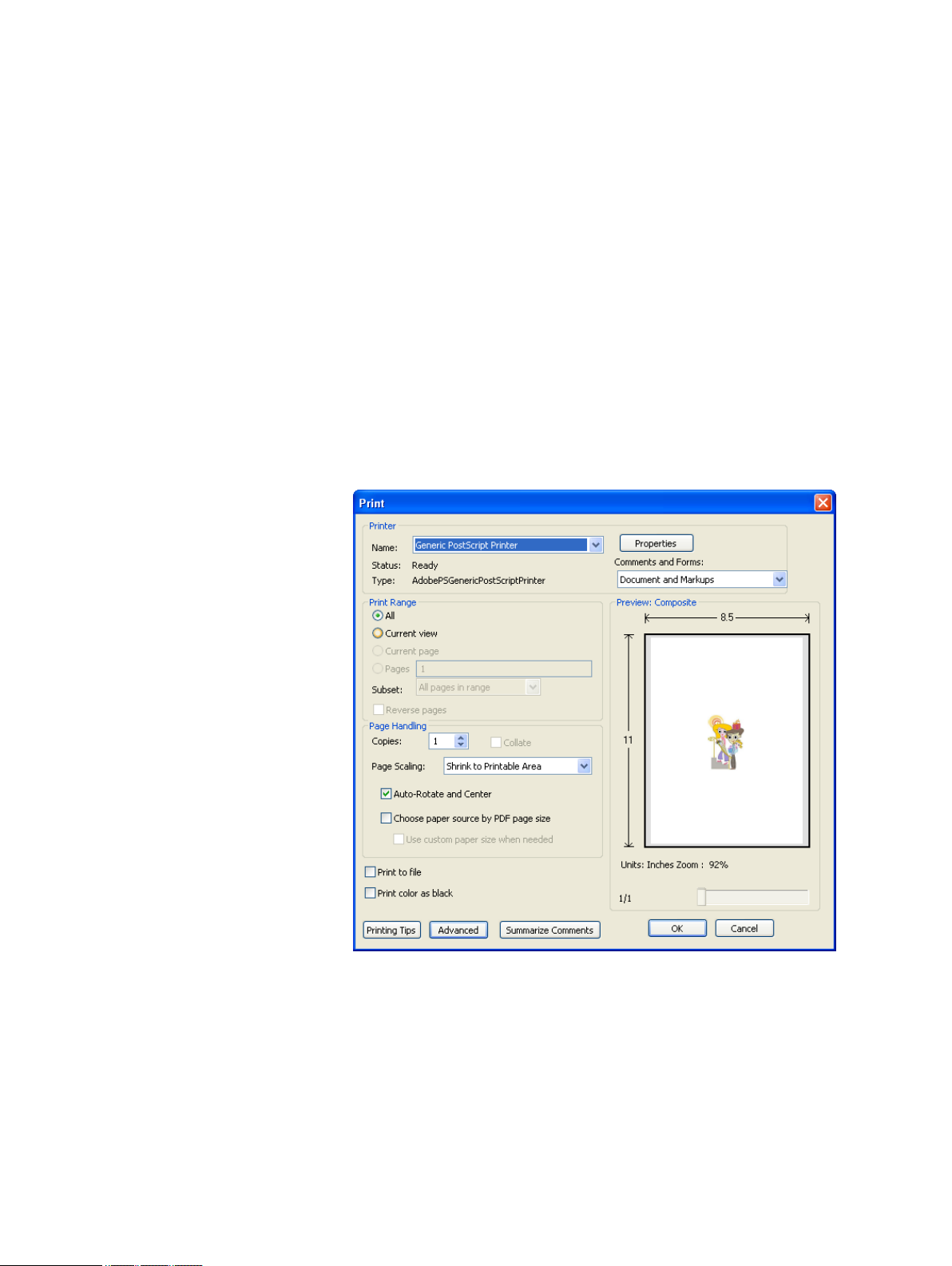
Printing this guide
Change the paper size to print this document on any printer.
1. Open the PDF file in Adobe® Acrobat®.
2. From the File menu, select Print.
The Print dialog box appears.
Getting started
Select the desired paper size, for example, A4 or letter.
3.
4. In the Page Scaling list, select Fit To Printable Area or
Shrink To Printable Area.
The names in the Page Scaling list vary according to the version of
Note:
the Adobe Acrobat software.
5. Click OK.
This document is printed to the selected paper size to your printer.
Page 10

2 Chapter 1—Getting started
System overview
The Xerox CX Print Server, Powered by Creo®, for the Xerox
®
DocuColor® 7002/8002 Digital Press is an on-demand prepress
system that uses advanced prepress technologies to drive the
Xerox DocuColor 7002/8002 Digital Press.
The CX print server enables you to print from computers running
the Microsoft® Windows® operating system and Apple® Mac OS
®
operating system software. Using raster image processor (RIP)
technology, the CX print server converts image files in pagedescription language (PDL) formats—for example, Adobe
PostScript®, PDF, and variable data printing formats—to a suitable
ready-to-print (RTP) format for direct high-quality digital printing.
The CX print server also streamlines the printing process by
allowing you to print with preset workflows.
In combination with the printer, the CX print server enables you to
efficiently print flyers, brochures, pamphlets, dummy catalogs, shortrun trials, and print-on-demand publications. When installed as a
network printer with the CX print server, the press prints at the fullrated speed.
The CX print server combines RIP functionalities, automation,
control tools, and special hardware development capabilities with
Windows-based architecture.
Hardware and software components
The CX print server includes:
●
Creo hardware, including the interface board
●
Off-the-shelf hardware
●
A DVD-RW drive with DVD burning software
●
The following software:
❐ CX print server software
❐ Adobe Acrobat 9.0 and PDF 1.8 (PDF library 9.0)
❐ Enfocus PitStop Edit
❐ Microsoft Internet Explorer® 6
Supported formats
The CX print server supports the following file formats:
Page 11
Overview of the Workspace 3
●
PostScript (composite or pre-separated files) (levels 1, 2, and 3)
●
Adobe PDF (versions 1.2 through 1.7)
●
EPS
●
Creo VPS (Variable Print Specification)
●
Xerox VIPP® (Variable Data Intelligent PostScript PrintWare)
●
VIPP.VPC (VIPP Project Container)
●
PPML (Personalized Print Markup Language)
●
PPML.zip
●
File formats from various prepress systems—for example,
Kodak® Brisque® and TIFF/IT software
●
CT, LW
●
JPEG
●
TIFF
●
Pre-separated formats
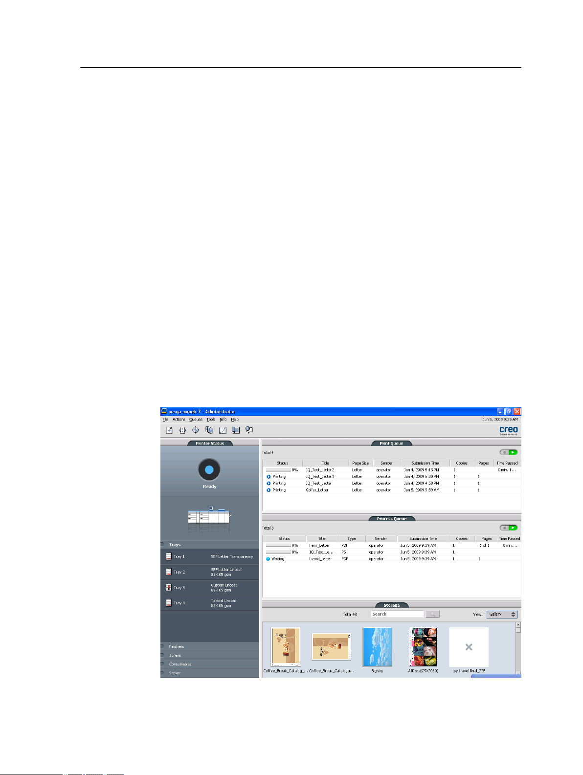
Overview of the Workspace
When you start the CX print server software the workspace
automatically appears.
The workspace contains different areas that enable you to monitor
your job during the process and print stages. In addition, the
Page 12
4 Chapter 1—Getting started
workspace includes tools and options that enable you to fully
customize and manage your server and jobs.
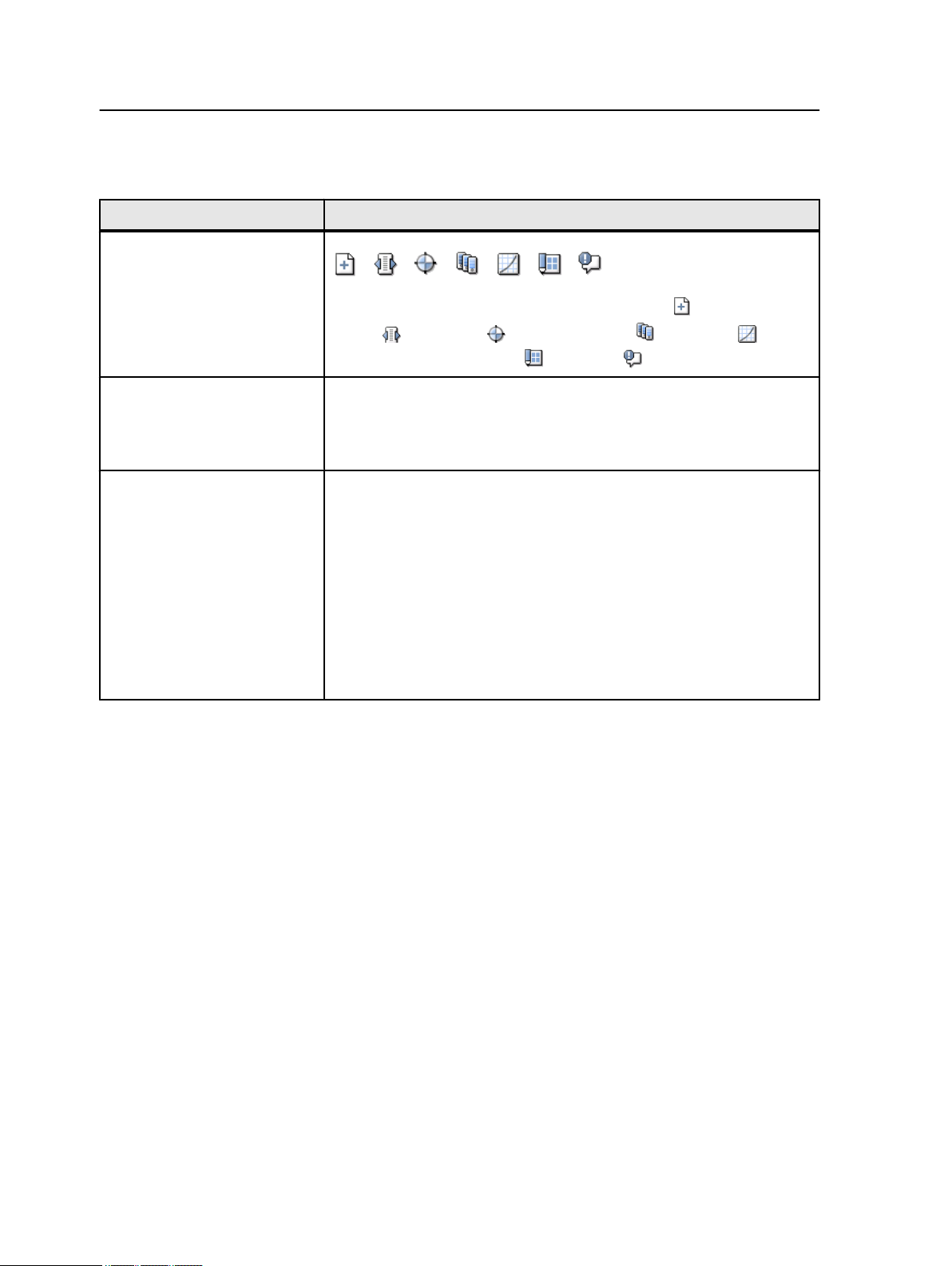
Workspace area Description
Toolbar
Consists of shortcut buttons for the Import window , Resource
Center
Imposition Template Builder
Printer Status panel The Printer Status pane displays information about the current printer
status—for example, Printing, Ready, Warming up.
The printer icon changes according to the configuration of the printer
and the finishing devices connected.
Resource details Click Trays, Finishers, Toners, or Server to display information about
the size and type of paper in each tray, the connected finishing devices,
the available toner, and disk space and network details.
Under Server, you can also view the date that the printer was most
recently calibrated. Progress bars display information about incoming
and outgoing jobs.
, Calibration , Spot Color Editor , Gradation ,
, and Alerts
.
If there is a problem with one of the printer components or with the
server, a red indicator appears in the printer icon and next to the
relevant component—for example, if a tray is empty.
Page 13
Turning on the CX print server 5
Workspace area Description
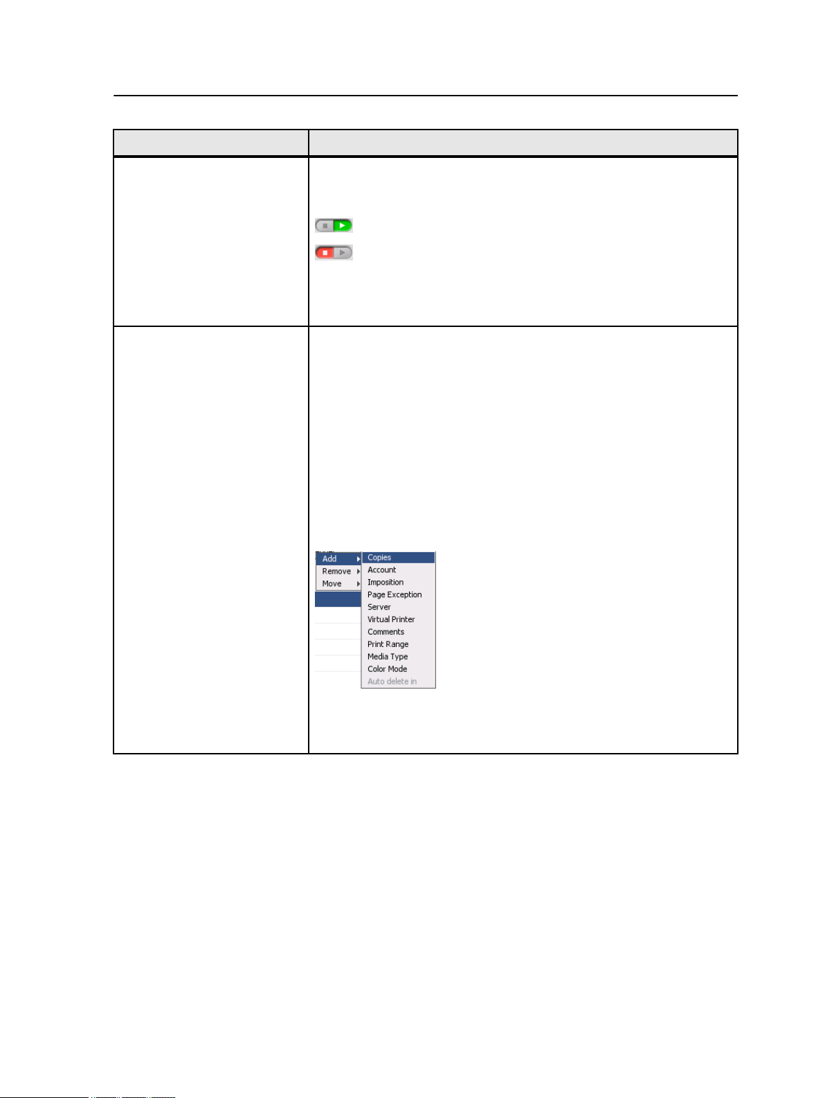
Process and Print queues Consists of the Process Queue, which lists the files to be processed.
After a file has been processed successfully, it moves either to the Print
Queue (the upper area) or to the Storage area.
Indicates that the queue is ready for processing or printing.
Indicates that the queue is suspended. You will need to release
the queue in order to process and print the jobs in this queue.
Note: When a queue is suspended you can open and edit the job
parameters of a job.
Storage area The Storage area contains files that:
●
were successfully printed
●
were held, were aborted, or failed during processing or printing
●
were sent directly from the client workstation to the Storage area or
were imported to the Storage area.
There are three different views available in the Storage area: List,
Preview, and Gallery.
You can modify the columns and information that is displayed in the
Storage area.
To add or remove a column, right-click on the Storage area title bar and
select the column that you want to add or remove.
Note: If you select Copies, then you will be able to change the number
of copies for that job and submit it for printing without opening and
editing the job parameters.
Turning on the CX print server
1. Turn on the monitor.
2. Open the front panel of the CX print server, and push the
power control button.
The power indicator on the front panel lights up, and the
Windows operating system logon screen appears.
The CX print server splash screen appears, followed by the
workspace.
Page 14

6 Chapter 1—Getting started
Notes: If the workspace does not automatically appear, open the application
from the Windows Start menu. By default, you can open the workspace
without logging on each time. If you want each user to log on, clear the Auto
Log On checkbox in the Preferences window, and then assign each user an
access level and password.
There are three different access levels available:
●
Operator (default): Enables the user to operate the CX print server and
configure the Preferences.
●
Administrator: Enables the user to access all features and settings on the
CX print server
●
Guest: Enables the user to import a job through an existing virtual printer
and view the workspace
Note: By default the Windows screen saver is off. If the screen saver is
activated with a password, then the user name is set to operator and
password is spire.
Turning off the CX print server
Requirements:
If you are working in the IPDS workflow mode, you can not shut
down the software until the IPDS connection is disconnected.
1. From the File menu in the workspace, select Exit.
A confirmation message appears.
2. Click Yes.
The CX print server software closes. This may take a few
minutes.
If you move the cursor over the server icon on the taskbar, the
Note:
following tooltip appears: Color Server is Shutting Down. Please Wait.
3. Verify that the CX print server icon does not appear on the
taskbar.
4. From the Windows Start menu, select Shut Down, and click
OK.
5. After the CX print server has shutdown, you can now turn off
the the printer
Page 15

Setting up your computer for printing
2
Setting up your computer overview
Printing Methods
Some methods for printing with the CX print server:
●
Submit the job to one of the CX print server virtual printers. The
job is spooled and then processed or printed (according to the
selected job flow of the virtual printer). If you use this method,
you can print from any software—for example, Microsoft Word—
and use any file format from any Windows and Apple Mac®.
●
Drag the job to a hot folder. The job is spooled and processed or
printed (according to the selected job flow of the corresponding
virtual printer). If you use the hot folder method, you can print
most PDL files—for example, PostScript, PDF, EPS, Variable
Print Specification, and PPML.
Network printers
To print your file using a CX print server virtual printer, you first
need install the virtual printer as a network printer on your computer.
After you install a network printer on your computer, you will be
able to submit files for printing. The network printers are installed
by default with the Print Driver software. You can change the
default settings of the network printer to use the PPD parameters
instead of the Print Driver software.
The CX print server supports printing from the following operating
systems:
●
Mac OS X
●
Windows 2000, Windows XP, Microsoft Windows Vista®,
Microsoft Windows Server® 2003, and Windows Server 2008
The CX print server provides default network printers, referred to
here as virtual printers.
A virtual printer contains preset workflows that are automatically
applied to all print jobs processed with that virtual printer. The
default virtual printers are published on the network with specific
parameters set for processing and printing.
Page 16

8 Chapter 2—Setting up your computer for printing
The default virtual printers are:
●
ProcessStore
Files sent to this printer are automatically processed and stored
in ready-to-print (RTP) format in the Storage area. Later, you
can submit an RTP job for printing, or change the parameters of
the job and resubmit it for processing or printing.
●
ProcessPrint
Files sent to this printer are automatically processed and
immediately sent to the press for printing.
●
SpoolStore
Files sent to this printer are spooled to the Storage area and
wait until you submit them for processing and printing. The files
remain in PDL format (such as PS, PDF, VIPP, VPS, and PPML).
Print Driver software
Use the Print Driver software to set job parameters when you are
submitting a job to the CX print server from any application in your
computer. The Print Driver software is automatically installed on a
Windows computer when you set up a network printer.
On a Mac computer, you must install the Print Driver software manually.
Note:
In the Print Driver window, you can perform the following actions:
●
Define or change job parameters regardless of whether your
computer is connected to the server
●
Lock a job
●
Save a set of parameters. Sets are useful when you want to
print different jobs with the same parameters, or if you want to
reprint a job.
●
Retrieve a saved set of parameters
●
Check the status of the printer
●
Define PostScript parameters for the job
●
Preview imposition layout
Page 17

Setting up printing on a Windows computer 9
Setting up printing on a Windows computer
Adding a network printer to your Windows computer
To print from a Windows computer, you first need to add a CX print
server virtual printer to your client workstation.
Tip: Following are some shortcut tips for setting up a printer. The full
procedure is detailed below.
●
Locate the CX print server in My Network Places, and then double-click
on the network printer you want to install. The network printer is
automatically installed on your computer and appears in the list of printers.
●
If you know the name of your CX print server, click Start > Run, and then
type \\server name. The CX print server opens showing a list of all the
network printers. Double-click on the network printer you want to install.
1. From the Start menu, select Settings > Printers and Faxes.
The Printers and Faxes window appears.
2. In the Printer Tasks area, select Add a printer.
Your computer might have slightly different wording from what
Note:
appears in this task.
The Add Printer Wizard appears.
3. Select Next.
4. Select A network printer, or a printer attached to another
computer, and then click Next.
5. Select Browse for a printer, and click Next.
6. Find the CX print server, and double-click it to display the list
of network printers.
7. Select the desired printer, and click Next.
8. When a message appears, click Yes.
9. Select one of the following:
●
Yes if you want to set this printer as the default printer on
your computer.
●
No if you don't want to set the printer as the default printer
on your computer.
10. Click Next.
11. Click Finish to close the wizard.
The CX print server network printer is added to your printer list. In
addition, the Print Driver software and PPD file are automatically
installed.
Page 18

10 Chapter 2—Setting up your computer for printing
Loading the Print Driver software for the first time
Requirements:
A network printer must be defined on your computer.
Load the Print Driver software after installing a network printer so
that the CX print server will be ready for printing.
1. Open a file with its corresponding application—for example,
open a PDF file in Adobe Acrobat.
2. From the File menu, select Print.
The Print dialog box appears.
3. Select one of the network printers—for example, Print and
click Properties.
A message tells you that the software is loading.
Note: This process may take a few minutes.
After the software loads successfully, click Finish. The job
parameters window appears.
4. Close the job parameters window and printer Print Dialog box
to complete the installation of the Print Driver.
The network printer is set up for printing using the Print Driver
software.
Deactivating the Print Driver software
Deactivate the Print Driver software if you want to access the PPD
file parameters. The Print Driver software is active by default.
1. From the Windows Start menu, select Settings > Printers
and Faxes.
2. Right-click the printer icon of the network printer you want to
deactivate the Print Driver, and select Properties.
3. Click the Print Driver tab.
4. In the Enable enhanced user interface, list select off.
5. Click Apply.
6. Click OK.
Page 19

Removing the Print Driver software 11
Removing the Print Driver software
Perform this procedure if you need to upgrade to a later version of
the Print Driver software or if you want to install the Print Driver
software for a printer with a different name.
Requirements:
All applications must be closed.
1. From the Windows Start menu, select Settings > Printers
and Faxes.
2. Right-click the network printer that you want to remove, and
select Delete.
3. In the Printers and Faxes window, from the File menu, select
Server Properties.
4. In the Print Server Properties dialog box, click the Drivers tab.
5. Select the appropriate printer, and click Remove.
The driver is removed.
6. From the Windows Start menu, select Run.
7. In the Open box, type \\, followed by the host name or IP
address of the server, and click OK.
The server window opens.
8. Navigate to \Utilities\PC Utilities\Driver Extension.
9. Perform one of the following steps:
Downloading fonts
●
If you are using Windows XP, double-click
DEX_Uninstaller.exe
●
If you are using Windows Vista, right-click
DEX_Uninstaller.exe, and select Run as Administrator.
The Print Driver software is removed.
Use the HF_Fontdownloader hot folder, located in D:
\HotFolders, to install new or missing fonts to the CX print server
fonts directory.
The HF_Fontdownloader hot folder can be used with the
following operating systems:
●
Windows Vista
●
Windows XP
●
Windows 2000
●
Windows Server 2008
Page 20

12 Chapter 2—Setting up your computer for printing
●
Windows Server 2003
●
Mac OS X
Drag the required fonts from the computer to the
HF_Fontdownloader hot folder.
Setting up printing in Mac OS
Installing the Print Driver software in Mac OS
During the installation of the Print Driver software, the PPD file is
automatically copied to your computer. In versions earlier than
Mac OS 10.4, you must copy the PPD manually.
1. From the Go menu, select Connect to Server.
2. In the Server Address box, type your server address, and
click Connect.
3. In the Connect as area, select Guest.
4. Click Connect.
5. Select Utilities and click OK.
6. Select the Mac Utilities folder.
7. Double-click the
CX8002_ColorServerPrintDriverInstaller.dmg file.
The Welcome screen appears.
8. Click Continue.
9. In the message window, click Continue.
10. In the Software License Agreement window, click Continue.
11. Click Agree to agree to the terms and continue with the
installation procedure.
12. Click Change Install Location.
13. In the Select Destination area, select the destination volume
in which you want to install the Print Driver software, and click
Continue.
14. Click Install.
15. Type your login name (if necessary) and password, and click
OK.
16. Click Close.
The Print Driver software and PPD are installed.
Page 21

Defining a printer with the Print Driver software in Mac OS 13
Note: If you deactivate the Print Driver software, you can still use the PPD
because it has been installed already.
Defining a printer with the Print Driver software in Mac OS
Requirements:
The following information must be available:
●
IP address and computer name of your CX print server
●
Name of the network printer that you want to use with the Print
Driver software
1. On your Mac computer, open the System Preferences window
and double-click Print & Fax.
2. In the Print & Fax window, click the add (+) button.
Note: You can also define your printer using the Default option.
3. In the Add Printer window, select the IP tab, and enter the
following information:
●
In the Address box, type the address of your server.
●
In the Queue box, type the name of the network printer that
you want to use with the Print Driver software.
●
In the Name box, type a name for the printer.
●
In the Print Using list, select Other.
4. Navigate to Library / Printers / PPDS / Contents /
Resources / en.lproj, select either Europe_A4 or US_Letter,
and then select the CX8002v1.PPD.
5. Click Open.
6. Click Add.
7. Close the Print & Fax window.
The network printer is defined with the PPD file.
8. In the Print & Fax window, double-click the network printer.
9. Click Utility.
10. In the Enable Enhanced User Interface list, make sure that
On is selected.
11. In the Server Hostname box, type the IP address of the server.
12. Click Apply.
Page 22

14 Chapter 2—Setting up your computer for printing
Removing the Print Driver software
Perform this procedure if you need to upgrade to a later software
version of the Print Driver software.
Requirements:
All applications must be closed.
1. Open the System Preferences window, and double-click Print
& Fax.
2. In the Print & Fax window, select the network printer that you
want to remove.
3. Click delete (-), and then click OK.
4. Navigate to Library / Printers / Creo_Color_Server_Tools,
and delete the Creo_Color_Server_Tools folder.
5. Navigate to Library / Receipts folder, and delete all of the
CX*.pkg files.
The Print Driver software is removed. You can now upgrade the
Print Driver software.
You will need to reinstall the network printers that you removed after
Note:
you have upgraded the software.
Page 23

Calibration
3
Calibration overview
Obtaining the most satisfactory print quality on your printer
depends on a number of issues. One of the most important issues
is steady toner density. Toner density is affected by many factors
such as heat, humidity, and service settings. Toner density also
tends to vary over time. Such variations cannot be totally
eliminated, but you can perform the calibration process to
compensate for them.
The calibration process consists of creating calibration tables that
are mapped to a specific media type, paper weight, and screening
method.
You can create calibration curves using either of the following
options:
●
Inline spectrophotometer: Enables you to automatically calibrate
and create profiles for your digital press. The automatic
calibration tool allows you to create calibration curves for
several screening types.
●
Calibration wizard: The Calibration wizard guides you through
printing a color chart, scanning the streams of color patches in
the color chart, and creating a calibration table based on the
scanned measurements.
The CX print server uses the data in this table to compensate for
the differences between the the actual, measured density level,
and the target level, the target density.
You should create calibration tables in the following instances:
●
When you use a new paper stock
●
When prints show “color casts”
●
After machine maintenance or hardware changes
●
If there are drastic ambient changes (temperature and humidity)
●
Every 24 hours, to compensate for potential variations in toner
density
Page 24
16 Chapter 3—Calibration
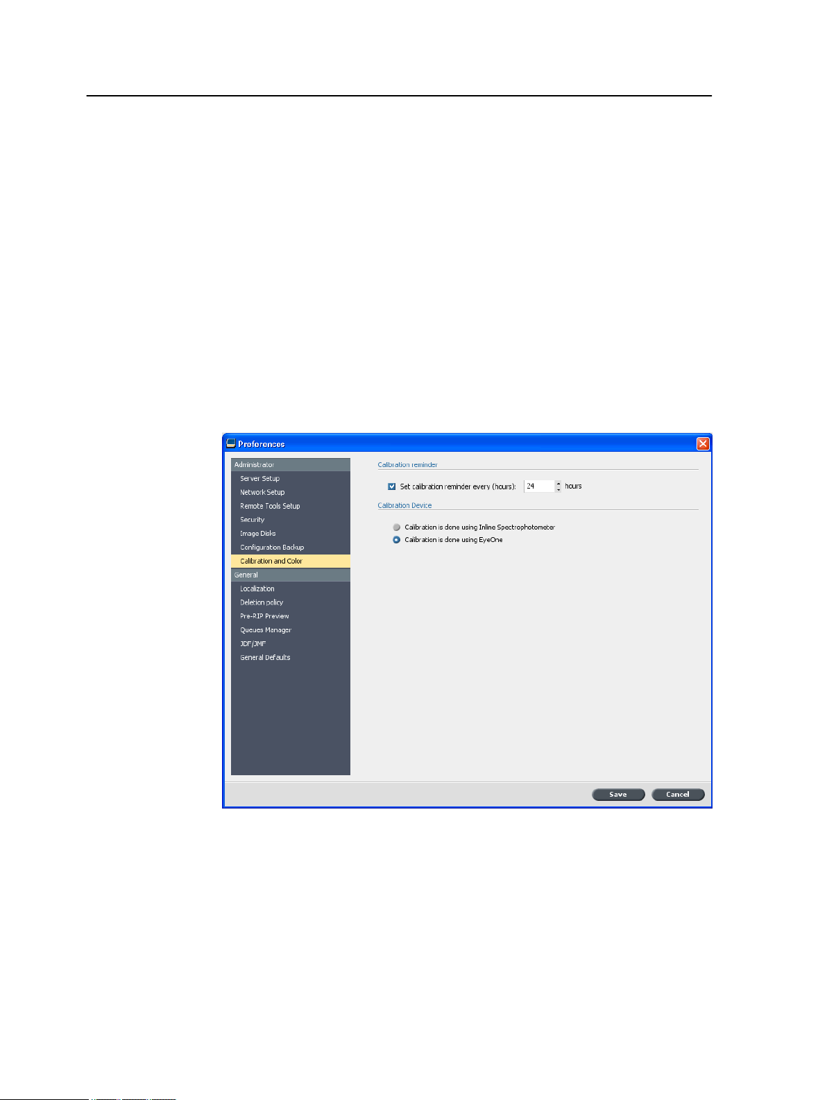
Defining the inline spectrophotometer as the calibration device
By default, the Inline Spectrophotometer is the selected
calibration device on the CX print server. If the X-Rite i1
spectrophotometer is connected to your CX Print Server, you can
switch to the Inline Spectrophotometer in the Preferences window.
1. From the Tools menu, select Settings.
2. Under Administration, click Calibration Device.
3. Select the Calibration is done using Inline
Spectrophotometer option.
®
4. Click Save.
The inline spectrophotometer is defined as the default
measurement device for creating calibration tables and destination
profiles.
Page 25
Creating a calibration table using the Inline Spectrophotometer 17
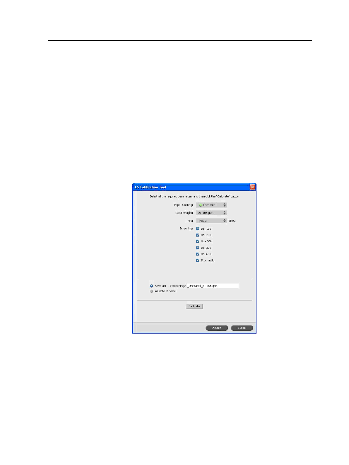
Creating a calibration table using the Inline Spectrophotometer
Requirements:
The media that you choose must be loaded as SEF, and the
printer must be ready for printing.
1. Suspend the Process Queue.
2. Make sure that the Print Queue is released and that no jobs
are running.
3. From the Tools menu, select Calibration.
4. Define the parameters as follows:
a. In the Paper Coating list, select either Coated or
Uncoated for the paper type.
You can only select the media that is loaded in the printer.
Note:
b. In the Weight list, select the weight of the paper stock.
c. In the Tray list, select the tray where the paper stock is
loaded for the calibration.
Page 26

18 Chapter 3—Calibration
d. In the Screening area, select the screening method for
which you want to create a calibration table.
Note: You can select all screening methods. The server creates a
calibration table for each screening method that you select.
e. The Save as box displays an automatic name for the
calibration tables according to the media name. If required,
you can type a different name. The screening number is
appended to the resulting calibration file name.
5. Click Calibrate.
During the calibration process, a progress bar appears at the
bottom of the Calibration Tool window. The progress bar
indicates the calibration stages: printing the chart, measuring
it, and saving the measurements.
When the calibration process is completed, a check mark
appears next to the selected screening methods.
6. Click Close, when the calibration is completed and after all
green check marks appear.
The new calibration table (or tables) is added to the list of
calibration tables in the Calibrations window and the Media and
Color Manager in the Resource Center.
To apply one of these calibration tables to your job, open the job
parameters window, and select Color > Calibration. Select from
the list the calibration table you want to apply to your job, and then
submit the job for printing.
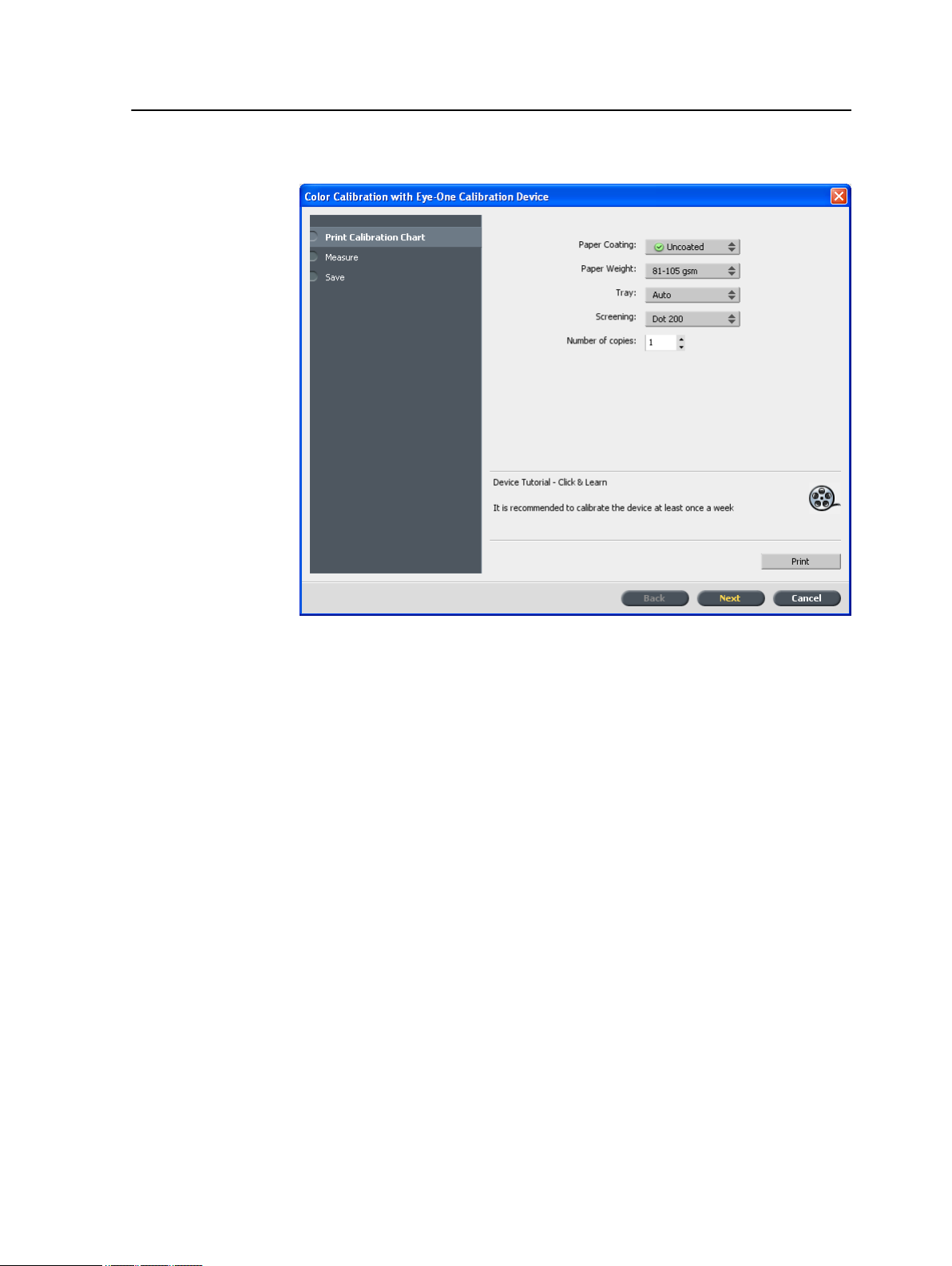
Creating a calibration table using the X-Rite i1 spectrophotometer
Requirements:
●
Your spectrophotometer must be connected to the USB port on
the CX print server.
●
Install the driver when prompted for the first time connecting the
device. Refer to the spectrophotometer product documentation
for more details.
●
Make sure that your spectrophotometer is calibrated by placing
the spectrophotometer on its plate.
●
Make sure that the Print Queue is not suspended and is ready
for printing.
●
Make sure the X-rite i1 spectrophotometer is selected in the
Preferences window.
Page 27
Creating a calibration table using the X-Rite i1 spectrophotometer 19
1. From the Tools menu, select Calibration.
2. In the Number of copies box, type the number of copies you
want to print.
3. Click Print.
The calibration chart prints.
Page 28
20 Chapter 3—Calibration
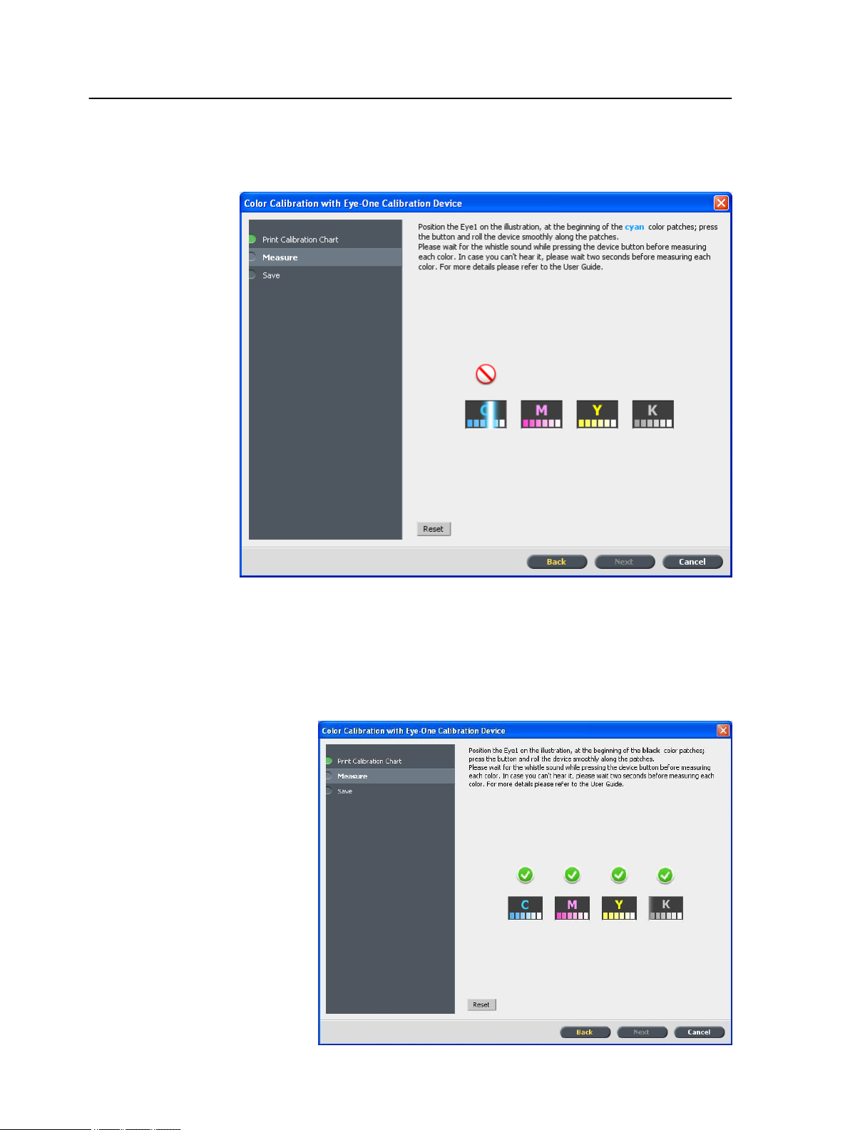
4. Step 2 of the Color Calibration Wizard appears. Follow the
instructions in the wizard to complete the calibration.
5. After each color sweep, wait for the check mark to appear next
to the appropriate icon and follow the instructions as listed.
Make sure that the separation columns on the chart are scanned in
Note:
the order they appear in the icons: Cyan > Magenta > Yellow > Black.
When all of the separation columns have been successfully
scanned, a check mark appears next to all icons.
Page 29

Mapping jobs to calibration tables 21
Notes:
●
If at any stage the scanning has not been completed properly, click
Reset and scan again.
●
If an error occurs while you are scanning the chart, an alert message
appears. Click OK and re-scan the charts.
6. To save the calibration table, do one of the following:
●
Select As default name to automatically name the
calibration table using the screening method, meda type,
and date.
●
Select Save as to type your own name.
Note: It is strongly recommended that you include the media type, weight,
and screening method in the calibration table file name.
7. Click Finish.
Mapping jobs to calibration tables
When you create a calibration table, the calibration table is based
on the media type, paper weight, and screening method that you
selected during the calibration process. Any job that has the
specific media type, paper weight, and screening method that you
selected, will automatically be mapped or linked to this calibration
table.
In the Job Parameters window, under Color > Calibration, the
Linked option is selected by default.
When you send your job to print, because the calibration table is
linked to the job, it is automatically used when the job is printed.
See also:
Mapping media using the Media and Color Manager
tool on page 52
Page 30

22 Chapter 3—Calibration
Page 31

Printing a file in Windows and Mac OS
4
Printing a file to the CX print server
Requirements:
A network printer must be defined on your Windows and Mac
computer.
This task describes how to print from a Windows computer, and
can also be followed for printing from a Mac.
1. Open a file with its corresponding application—for example,
open a PDF file in Adobe Acrobat.
2. From the File menu, select Print.
3. In the Name list, select the desired network printer—for
example, <servername>_Print.
4. (Optional) To modify job parameters, perform the following steps:
a. Click Properties.
b. Modify the parameters.
c. Click OK.
5. Click OK.
6. In the Print dialog box, click OK.
The file is sent to the CX print server where it is processed and
printed.
Using a hot folder to print
Use hot folders to automate your workflow and to save time by
simultaneously submitting multiple files for printing.
You can use hot folders to process and print files from any
computer. The following procedure can also be followed on a Mac
computer.
1. On your Windows desktop, double-click the My Network
Places icon.
In Mac OS, from the Finder menu, select GoConnect to
Server.
Page 32

24 Chapter 4—Printing a file in Windows and Mac OS
2. Locate the CX print server, and double-click it.
A list of all the shared folders, hot folders, and printers appears.
3. Double-click the desired hot folder—for example,
HF_ProcessPrint.
Tip: You can drag the hot folder icon to your desktop to create a shortcut to
the hot folder for future use.
4. Drag the desired files to the hot folder.
All the files are processed and printed automatically, according to
the hot folder workflow.
Password protect jobs
The CX print server enables you to protect sensitive data and
control its printing. You can lock and password protect a job on
your computer and submit it for printing on the CX print server.
Requirements:
●
A CX print server network printer must exist on your client
workstation.
●
The printer status on the CX print server must be in Ready mode.
Using the Print Driver software, you can apply a password to a job
that was created in any application. Whoever prints or reprints the
job must use the password to unlock it and release it for printing.
1. On your computer, open a file—for example, a PDF file.
2. From the File menu, select Print.
3. In the Print dialog box, in the Name list, select the name of the
network printer that you want to submit your file to.
4. Click the Properties button.
The Print Driver window appears.
5. In the Print Driver window, click the Lock button .
The Secure Printing dialog box appears.
6. In the Password box, type a password consisting of four
numeric characters—for example, 9999.
The password must consist of exactly four numeric characters.
Note:
7. Click OK.
The job is password-protected, and nobody can print it without
using the password.
8. In the Print Driver window, click OK.
The password-protected job is submitted to the network printer
where it is sent to the CX print server for processing and printing.
Page 33

Password protect jobs 25
9. In the Print Queue area, right-click the password-protected job
that you want to print, and select Release to print.
The Secure Printing dialog box appears.
10. In the Password box, type the password that was defined for
this job.
11. Click OK.
Your job is unlocked and printed. When the printing is finished,
the job is automatically deleted.
See also:
Secure printing overview on page 38
The Preferences window on page 123
Page 34

26 Chapter 4—Printing a file in Windows and Mac OS
Page 35

Printing from the color server
5
Importing and printing a job
You can import a job:
●
When a page-description language (PDL) file—for example,
PDF or PostScript—is created on a computer that is not
connected to the CX print server
●
When a PDL file is located on a folder on the network, or on
external media, such as a CD-ROM
●
When the desired file resides locally on the CX print server
1. From the File menu, select Import.
2. To access the desired files, click the up one level button, or
double-click on the file folders to go down the file tree.
3. In the upper list in the Import window, select the desired file(s)
and click the add button.
Use SHIFT or CTRL to select several files or CTRL+A to select all the
Note:
files. If desired, add the same file more than once.
The file(s) appears in the lower list.
4. Select a printer from the Virtual printer list.
To remove a file, select the desired file in the lower list in the Import
Note:
Job window and click the remove button.
5. Click Import.
All files currently listed on the lower list are sent to the CX print
server to be processed and printed as defined in the selected
virtual printer.
6. If your job is moved to the Storage area, submit the job for
printing.
Previewing and editing a PDF file
In the Storage area, right-click the PDF file that you want to
preview or edit, and select Job Preview & Editor.
The file opens in Adobe Acrobat.
Page 36

28 Chapter 5—Printing from the color server
Editing a job overview
You can preview and edit any PDL and RTP job that is in Storage
Area. PDL files are opened in Adobe Acrobat software, and RTP
files are opened in the Job Preview & Editor tool.
In Adobe Acrobat, you can view and edit the PDL job as you would
normally. In addition, this version of Adobe Acrobat includes the
Pitstop plugin that includes more editing tools. For more
information, refer to the documentation included in the Pitstop and
Acrobat software.
In the Job Preview & Editor window you can view thumbnails of
the job while you navigate to the various pages of a job. For an
imposed job, you can view the imposed sheets, including the
layout of the pages on each sheet. You can also view the pages'
orientation, crop marks, and fold marks.
Jobs that you edit in the Job Preview & Editor window cannot be reRIPed. After a job is saved in the Job Preview & Editor window, it
is a new RTP file without an associated PDL file. You cannot apply
parameters that require re-RIPing to such jobs.
Page 37

Moving a page in a job 29
Moving a page in a job
Move a page in an RTP job to a new location within the job.
When you move a page, the page numbers are updated accordingly.
1. In the Job Preview & Editor window, click the Thumbnails tab.
2. In the Thumbnail pane, click the page that you want to move.
3. Drag the page to the target location.
Note: The red marker indicates where the page will be inserted.
4. Click Save As to save the changes in the job.
Next:
Note: This feature can be used for the Xerox eBind solution to print the last
page of the job first (Nth page), then 1 to N-1.
Deleting a page from a job
1. In the Job Preview & Editor window, click the page that you
want to delete, and click Remove.
The page is deleted and the page numbers are updated
accordingly.
2. Click Save As to save the changes.
Merging one or more pages into a job
Merge one page, multiple pages, or all pages from one job into
another.
Requirements:
The RTP job that includes the page you want to copy must have
the same page size and orientation as the job that you are editing.
1. In the Job Preview & Editor window, click the Thumbnails tab.
2. In the left pane of the Thumbnails tab, determine a location
for the merged page. Click the page preceding this location.
A yellow outline appears around the selected page.
Page 38

30 Chapter 5—Printing from the color server
3. Click Merge Jobs.
Note: Only those RTP jobs that have the same page size and orientation as
the job that you are editing appear in the list.
4. Select the job with the page that you want to merge and click
OK.
The job opens in a separate window.
5. Do one of the following:
●
To merge one page, select the page that you want to merge
and click Merge.
Note: You can also drag the page from the job window to the desired
location in the left pane of the Thumbnails tab.
If you want to merge more than one page, repeat this step until all
desired pages are merged. You can also select different locations for the
merged pages in the Job Preview & Editor window.
●
To merge all pages into the job, click Merge All.
The merged pages are inserted into the desired location, and
the page numbers are updated accordingly.
6. Click Close to close the job window.
7. Click Save As to save the changes.
Replacing pages
In certain cases you may have a large job and you need to replace
one of the pages. In this case you can create an RTP file of the
page which you need to replace and then using the Job Preview &
Editor you can replace this page.
Requirements:
The RTP job that includes the page you want to replace must have
the same page size and orientation as the job you are editing.
1. Import and process the new page in order to create a new
2. Open the original RTP job in the Job Preview & Editor.
3. Merge the new RTP file using the steps described in Merging
4. Delete the incorrect page using the steps described in Deleting
RTP file.
one or more pages into a job.
a page from a job.
Page 39

Finding the CMYK values of a specific area 31
Finding the CMYK values of a specific area
Use the Show Color Values tool in the Job Preview & Editor
window to find out the CMYK values of a specific area on the page.
A processed job must be displayed in the Job Preview & Editor
window.
1. In the Job Preview & Editor window, click the Show Color
Values
2. Move the pointer to the location on the page where you want
to measure the color values and click.
The CMYK dot percentage values and spot color CMYK
equivalent values appear as a tool tip.
button.
Verifying the content of the job
Use Preflight features to check your document before processing
or sending a job to print.
The following preflight features are available:
●
PDF analyzer
●
Preflight check
●
Preflight report
PDF Analyzer
You can use the PDF analyzer to check imported PDF files for
problems that may affect processing. The PDF analyzer checks
the following elements:
●
Document: identifies incompatibilities of Acrobat software with
compression, encryption, security, and other properties
●
Pages: detects empty pages and identifies the page size,
annotations, and other properties
●
Fonts: determines whether specific fonts are in the PDF file and
whether they are embedded
●
Colors: detects color space information, spot colors, rendering
information, and color management settings
●
Images: identifies image resolution, whether images are
skewed or flipped, and whether images are compressed
Page 40

32 Chapter 5—Printing from the color server
●
OPI: detects whether OPI is used. If so, the PDF analyzer
detects the OPI version and determines whether any highresolution images in the OPI path are missing
●
Text and line art: identifies the size of text, the width of the
lines, white text, and objects and flatness tolerance
●
PDF/X: determines whether the file conforms to PDF/X-1a and
whether the file contains PostScript fragments
Preflight Check
The Run preflight parameter enables you to check the status of
key job components before the job is sent for printing.
During the preflight check, your job is RIPed and the missing
components are identified. The preflight check detects the status
of the following key job components:
●
High-resolution images or the wrong links to the high-resolution
images folder
●
Missing fonts
●
Spot colors that are not defined in the CX print server spot color
dictionary
●
Dynamic exception commands for a file that was submitted via
a dynamic page exceptions virtual printer
Preflight Report
The preflight report is a job-related report that provides information
about the status (missing or found) of key job components prior to
printing and enables you to correct your files accordingly.
It is especially useful to run the preflight check before you print a
complex job with a large quantity of pages or copies. The preflight
check detects the missing job components and displays them in
the Preflight Report dialog box. You can review the report and
resolve the missing components and thus save processing time
without error or failed messages constantly appearing.
If you run a preflight check and all key components are found, the
job is processed and printed according to the job flow that you
selected. If the test fails (missing key elements are detected), the
job is returned to the Storage window with the preflight report
available for inspection.
The preflight report always reflects the last preflight run. If more
than one preflight check is run on a job, the latest preflight report
overrides the previous. When a preflight report is produced, the
date and time of the preflight check are indicated in the Job
History window.
Page 41

Analyzing a PDF job 33
Note: Since the Preflight Report dialog box lists all key job components
(missing and found), you can use this report to view the existing (found) key
job components—for example, the list of the existing fonts in a job, and their
corresponding paths.
Analyzing a PDF job
You cannot use the PDF analyzer or perform a Preflight check on
PDF files that are locked or protected. If you do, a message will
appear stating that the file is encrypted.
1. In the Storage area, right-click the PDF file, and select PDF
Analyzer.
2. In the PDF PreFlight Settings area, do one of the following:
●
To check the entire PDF file, select Complete Document.
●
To check specific pages, select Pages, and enter the
desired page range.
3. If you do not want the report to automatically open when it is
generated, clear the Display report automatically check box.
4. If desired, change the report file name. By default, the report
file name consists of the original file name and the suffix _rep—
for example, if the file to be checked is sample.pdf, the report
file is named sample_rep.pdf.
5. If you want to save the report to a specific location, click
Browse and navigate to the desired location.
6. Click Run.
The PDF report is generated and opens automatically.
Page 42
34 Chapter 5—Printing from the color server
Performing a preflight check
Check the status of key components before the job is sent for
printing.
You cannot use the PDF analyzer or perform a Preflight check on
PDF files that are locked or protected. If you do, a message will
appear stating that the file is encrypted.
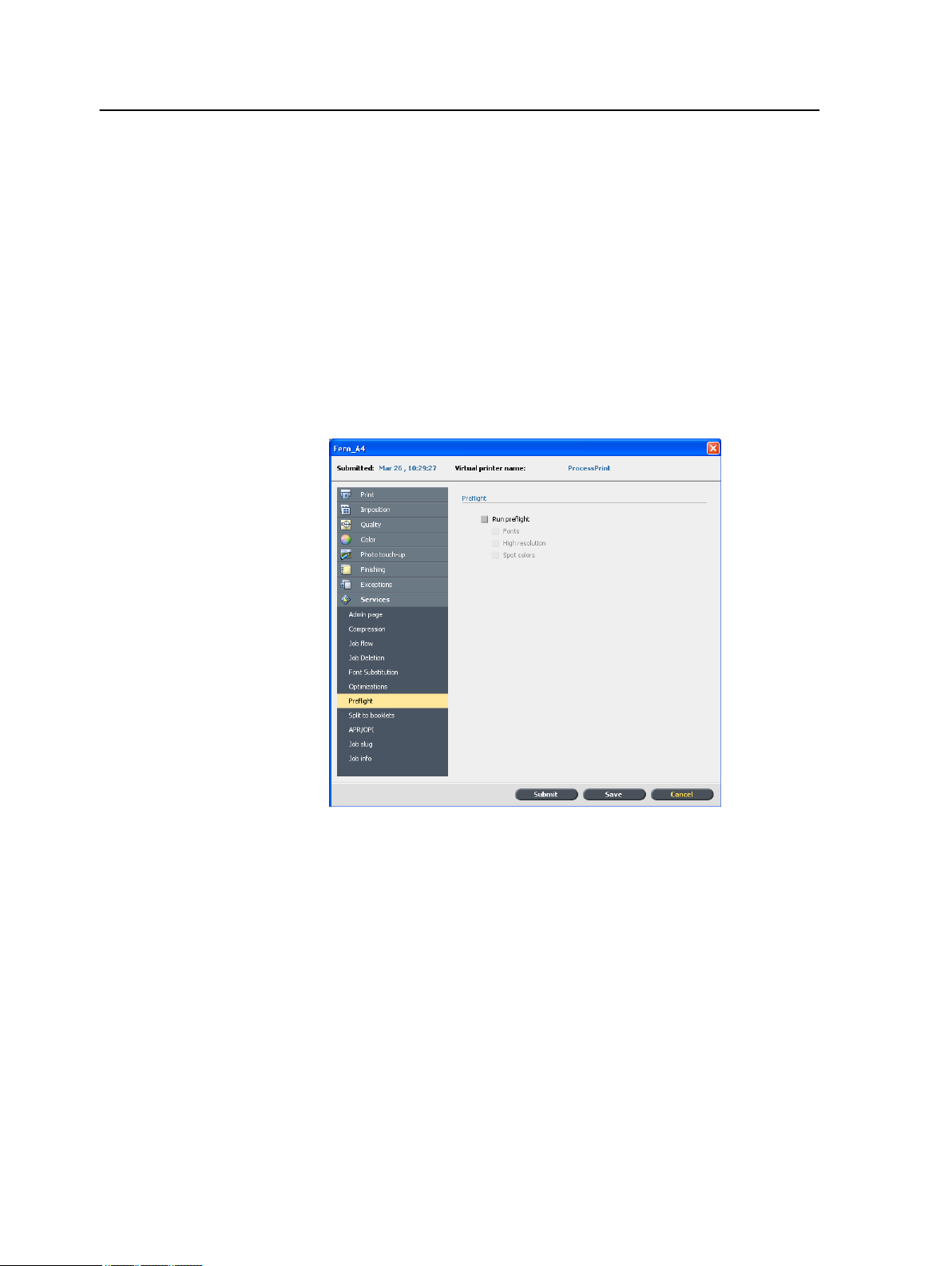
1. Open the Job Parameters window of the job that you want to
perform a preflight check.
2. Select Services, and then select Preflight.
3. Select the Run preflight check box.
All four check boxes of the key job components are
automatically selected.
4. Clear any check box that you don't want to include in the
preflight check.
If one of the selected job components is missing, the job status at the
Note:
end of the preflight check is failed, and the job is transferred to the Storage
window. Information about missing components appears in the Job History
window.
5. Click Submit.
The results of the preflight check are displayed in a Preflight report.
Page 43

Viewing and printing a preflight report 35
Viewing and printing a preflight report
1. Right-click the job in the Storage area, and from the menu,
select Preflight report.
2. Click the desired report option to see the results for that option.
3. To print the report, click Print.
4. To save the preflight report, click Save and browse to the
desired location.
Note: If more than one preflight check is run on a job, the latest preflight
report overrides the previous one.
Preflight Report window
The Preflight Report window is opened by right-clicking your job
and selecting Preflight report.
HiRes
Spot Colors
Fonts
Preflight options
Lists the missing and found high-resolution
images. If wrong links to the high-resolution
images folder exist, these are also listed.
Lists the missing spot color names (spot
colors that were not found in the spot color
dictionary), and the found spot color names
(spot colors that were found in the spot color
dictionary). The C, M, Y, and K columns
display the spot color CMYK equivalents.
If the status is Missing, the original CMYK
values that are embedded in the PS file are
used to emulate the desired spot color.
If the status is Found, the CMYK values that
are in the spot color dictionary are used.
Lists the name of missing fonts that are not
embedded in the file and do not exist in the
Font Library, and also fonts that are found.
Page 44

36 Chapter 5—Printing from the color server
Preflight options
The Source column indicates whether the font
is embedded in the file or was found in the
Font Library.
Exceptions
Missing
Not preflighted
Found
Lists the dynamic page exception commands
found in the file.
Indicators
Appears when key components in the job are
not found.
Appears if you did not select the preflight
option for the preflight check.
Appears when all of the files are found for the
selected option.
Show list
All
Found Only
Missing Only
Displays both missing and found options
Displays options that are found.
Displays options that are missing.
Proofing the job using color sets
Select the most appropriate predefined color set to print your job
with the best color quality. The Color Set option includes four
predefined color sets. Each color set provides you with the best
Page 45

Assigning a color set to your job 37
color and quality settings for a specific data type or a printed
product characteristic.
The color set options are as follows:
●
Photos of people:
Provides the best color and quality settings for jobs such as a
family photo album
●
Outdoor photos:
Provides the best color and quality settings for jobs that include
mainly photos of landscapes
●
Corporate documents:
Provides the best color and quality settings jobs that are mostly
office documents, such as presentation files, Web pages, and
files with charts and logos
●
Commercial materials:
Provides the best color and quality settings for jobs that include
both graphics and photos, such as advertising materials
To select the most appropriate color set for your job using the
recommended workflow, you can print a copy of your job with each
color set, review the printed sample jobs, and select the best print.
Then, in the Job Parameters window, you need to assign the color
set that provided the best results. If you know the color set you
want to use, you can assign a color set to your job without first
printing and reviewing samples jobs.
When you select a color set, some of the color and quality parameters
Note:
are disabled.
Assigning a color set to your job
After printing and reviewing the four sample files, you now need to
assign the most appropriate color set to your original job.
1. In the Storage area, double-click your job.
2. Under Print, select Color Set.
3. In the Set list, select one of the sets that achieved the best
printed color results, for example, Outdoor photos.
The job is assigned the color and quality parameters that are
predefined for the Outdoor photos set. The default color and
quality parameters that are configured for this job, are disabled.
4. To print your job, click Submit.
Collect the printouts and review the color quality.
Page 46

38 Chapter 5—Printing from the color server
Secure printing overview
The CX print server enables you to protect sensitive data and
control its printing.
Following are some of the options available:
●
The Disk Wipe utility enables you to work in a more secure
environment, by permanently removing data left by files that
you have deleted.
●
Password Protect Jobs (set in the Print Driver software)
●
Deletion policy (set in the Preferences window)
See also:
Password protect jobs on page 24
The Preferences window on page 123
Page 47

Managing jobs
6
Archival and retrieval of jobs
To keep enough disk space free, back up jobs and their related
files to an external server and then delete them from the Storage
area. You can retrieve archived jobs and files later for further use.
Archiving is a method of backing up and storing a job and enables
you to increase the available space on your disk. A cabinet file (a
compressed file) that contains all the files related to the archived
job is created at the selected location. The archived job retains its
current status (that is, completed, failed, held, or aborted) and is
archived with the information in its job parameters and its Job
History windows.
Note: The CX print server automatically archives large jobs to several cabinet
files.
Archiving a job
When retrieved, the archived job retains the original job name, not
the name assigned when archived.
Back up and store a job so that more disk space becomes available.
Requirements:
A folder for storing the archived job.
1. In the Storage area, right-click the job that you want to archive
and select Archive.
2. Locate the desired folder, and then click Archive.
A cabinet file (a compressed file) that contains all the files
related to the archived job is created at the selected location.
3. Delete the job from the Storage area.
Next:
If you are archiving a VDP job, then you will need to archive the
cached elements separately.
Page 48

40 Chapter 6—Managing jobs
Retrieving a job
Requirements:
You can only retrieve jobs that have been archived.
Note: If you are retrieving a VDP job, then you need to restore the cached
elements first.
When you retrieve a job, the archived job retains the original job
name, and not the name assigned when archived. The files related
to the job (for example, PDL) are also retrieved and the cabinet file
is not deleted.
You can retrieve more than one job at a time.
1. From the File menu, select Retrieve from archive.
2. Find the archived job under its archive name, and select the
related cabinet file.
3. Click Add.
The selected job appears in the lower list.
4. Click Retrieve.
The selected job appears at the top of the list in the Storage
area.
5. In the Job History window, verify that the file has been
successfully retrieved.
Forwarding a job to another CX print server
Requirements:
You can forward a job only if it is in the Storage area, and to a CX
print server with the same version.
1. In the Storage area, right-click the job, and select Forward to
> Other .
2. In the Host name / IP Address box, type the name or IP
address of the server that you want to forward the job to.
3. Click Find.
Page 49

Duplicating jobs 41
4. Select one of the following:
●
Send to Storage: to send the job to the selected server’s
Storage area.
●
Send to print: to send the job to the selected server’s Print
queue.
5. Click Send.
Duplicating jobs
Requirements:
You can duplicate a job only if it is in the Storage area.
In the Storage area, right-click the job, and select Duplicate.
The selected file is duplicated and is given the name of the original
job followed by the suffix _dup.
Note: The RTP job is duplicated to PDL format.
Resubmitting a job
In the Storage area, right-click the job that you want to submit
again, and select Submit.
RTP jobs are submitted to the Print queue; all other jobs are
submitted to the Process queue.
Printing copies of a job
Re-print more copies of a job directly from the storage folder
without opening the job parameters.
1. Right-click the title bar in the Storage area.
2. Select Add > Copies to add copies to the Copies column in
the Storage Area.
3. Select the job, and type in the Copies field the amount of
copies that you want to print.
4. Drag and drop the job to either the Process queue or Print queue.
Page 50

42 Chapter 6—Managing jobs
Job Reports
Accounting Viewer overview
The Accounting Viewer provides information about all of the jobs
that were printed successfully through the CX print server. The
report is in the form of a tab-delimited file and contains detailed
information about the printed job, for example, job size, processing
time, and number of pages. You can filter, sort, and print the
report. You can also export the report to a spreadsheet application
—for example, Microsoft Excel—where you can manipulate the
data. By default, all of the jobs that were handled during the past
90 days are listed.
You can access the Accounting Viewer from the Info menu.
The accounting report also includes pages that where printed as
black-and-white or color pages. The accounting report is based on
the job's original input and the parameters that are set in the Job
Parameters window. To ensure the correct billing for black and
white or grayscale jobs, perform the following actions:
●
Print a job in black and white
●
Print a job that contains gray RGB elements as black and white
or black only
Job Report overview
The Job Report window contains all of the information from the
Job Parameters window for a specific job. The Job Report window
presents the job parameters on a single sheet and may be printed
or exported as a text file.
To access the Job Report window, in the Storage area, right-click
the desired job, and select Job report. In the Job Report window,
you can print the report, or export it to a text file.
Ensuring proper billing
Accounting feature reports what was printed on black-and-white or
color pages.
The CX print server report is based on the job’s original input and
the parameters that are set in the Job Parameters window. To
ensure proper billing, you need to perform the following actions:
Page 51

Printing a job containing gray RGB elements as black and white 43
●
Print a job in black and white
●
Print a job that contains grayscale RGB elements as black-andwhite or black only
●
Print a job that contains grayscale CMYK elements as black only
Note: Grayscale TIFF and EPS images created in CMYK applications (such
as Adobe Photoshop® software) are counted correctly as B&W instead of
Color in both the CX print server and the Xerox DocuColor 7002/8002 Digital
Press billing meters.
Printing a job containing gray RGB elements as black and white
Print a job that contains gray RGB elements as black- and-white or
black only.
1. In the CX print server, open the Job Parameters window and
select Color > Ink Saving > Print grays using black toner .
2. Click Submit.
Printing a job in black and white
InSite jobs
When printing a job in black and white, discard all color information.
1. In the CX print server, open the Job Parameters window and
select Color > Color Mode, and select Grayscale.
2. Click Yes to discard all color information.
3. Click OK.
Printing a job containing gray CMYK elements as black and white
Print a job that contains gray CMYK elements as black- and-white
or black only.
1. In the CX print server, open the Job Parameters window, and
select Color > Protected colors.
2. In the CMYK area, select Preserve black color.
3. Click Submit.
If your site includes a Kodak InSite™ Prepress Portal system,
exporting your job as a Brisque job from the CX print server
enables you and your customers to use InSite to proof online with
geographically dispersed users simultaneously, append
annotations or comments, and approve or reject pages over the
World Wide Web using a standard browser.
Page 52

44 Chapter 6—Managing jobs
After the RTP job is created on the CX print server, you can export
it as a Brisque job from the Storage window. When the customer
logs on (using their unique username and password), they can see
the status of their jobs, view a thumbnail of all pages in each job,
and quickly identify which pages require further corrections. The
customer is able to measure color density, make annotated
comments, and approve pages.
The online proofing cycle is shortened and accurate, and
consequently, the need for reprints is reduced.
Exporting a job as an InSite job
Export as a Brisque job to proof online over the World Wide Web.
Requirements:
Your site should have an InSite Prepress Portal system.
You cannot export VDP jobs or RTP jobs that were originally VDP
jobs.
PDF2Go jobs
The CX print server creates a folder that includes an .assg file.
1. Select the job in the CX print server Storage area.
2. Right-click the job and from the menu, select Export as InSite
Job
3. Find the required folder, and click Save.
A Brisque job is created in the selected location.
You may now register the files on the InSite server and start the
approval cycle.
PDF2Go is a port through which you can export RTP and PDL
files, and convert them to a PDF file during export. The CX print
server is capable of exporting jobs that are standard PDF files,
both before and after processing. For an exported RTP job, the
PDF file includes the rasterized data of the job.
The operation converts the RTP information to raster files that can
be encapsulated in a PDF format. This process ensures that the
file can be processed and printed on any PDF printer.
Exporting to PDF enables you to send a copy of your job for
approval before printing.
Page 53

Exporting an RTP or PDL file as a PDF file 45
Exporting an RTP or PDL file as a PDF file
You can export any RTP or PDL file located in the storage folder to
PDF format.
1. Select the job in the CX print server Storage area.
2. Right-click the job and from the menu, select for RTP files
Export as PDF2Go or Export PDF for PDL files.
3. For RTP files, select Print Optimized or Screen Optimized,
and then click OK.
Screen optimized format creates a low resolution version of the job.
Note:
4. Browse to the folder that you want to save the file, and click
Save.
The PDF file can be printed on any printer.
Page 54

46 Chapter 6—Managing jobs
Page 55

Managing color
7
Color tools overview
The CX print server provides you with a number of tools and
options that enable you to adjust and improve the color quality in
your jobs.
The following tools are available:
●
Profile Manager
●
Spot Color Editor
●
Gradation Tool
●
Calibration table manager
●
Media and Color Manager
Managing color and profiles
A profile is a file that describes how a particular device reproduces
color. It represents the colorimetric behavior of a given device for
known media and imaging parameters (such as substrate/paper
stock, resolution, and inks). Profiles are used to reproduce color
from one device’s color space to another device's color space in a
consistent manner. They provide the necessary information to
convert color data between device-dependent color spaces and
device-independent color spaces. You use profiles to color manage
your system.
Color management is a series of steps taken to ensure that colors
are accurate and repeatable when transferred from one device to
another. Color management helps us reproduce the color
conceived by a graphic artist or photographer as closely as
possible on a monitor, a proof, or a press sheet. Color
management enables accurate and repeatable color reproduction,
within each device’s color capability, throughout the entire workflow.
Before you can print a color document, the color data in it must be
converted to the gamut of the printer. Whether performed by the
CX print server or a host-based CMS, the process of converting
color data for a printer is the same: the CMS interprets RGB object
data according to a specified source profile and adjusts both RGB
and CMYK data according to a specified output profile, also called
a destination profile by some color management systems.
Page 56
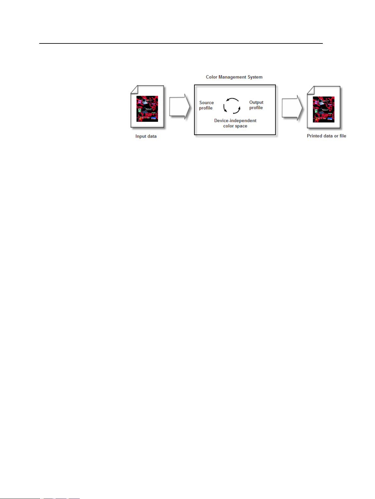
48 Chapter 7—Managing color
The source profile defines the RGB color space of the object’s
source: characteristics such as the white point, gamma, and type
of phosphors used. The output profile defines the gamut of an
output device, such as a printer. The Color Server (or host-based
Content Management System (CMS)) uses a deviceindependent
color space to translate between the source color space and the
color space of the output device.
The Profile Manager on the CX print server enables you to import
profiles which define the color space of your printer and are based
on the combinations of paper and toner that you are using. For
different media types, you need different destination profiles.
Creating a destination profile
Requirements:
Make sure that the printer is calibrated.
The media that you choose must be loaded as SEF, and the
printer must be ready for printing.
The Profiling Tool enables you to create destination profiles that
are best suited for the Xerox DocuColor 7002/8002 Digital Press.
You can create custom destination profiles for each press and fine
tune the color outputs of the press, improve color matching
between presses, and improve color consistency over time.
It is recommended that you create a destination profile for each paper
Note:
stock that you use.
1. Suspend the Process Queue.
2. Make sure that the Print Queue is released.
3. From the Tools menu, select Profiling Tool.
The Profiling Tool window appears.
Page 57
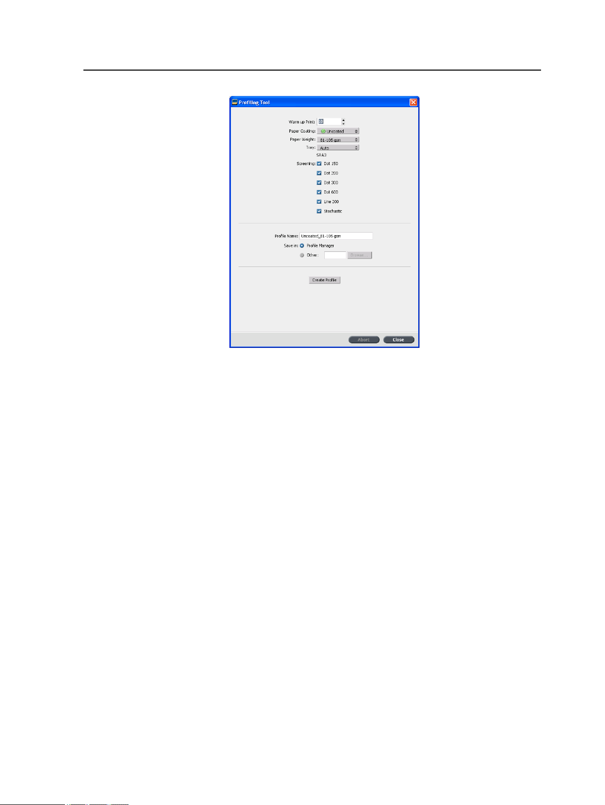
Managing color and profiles 49
4. Define the parameters as follows:
a. In the Warm up Print box, it is recommended that you type
10, which is the default value.
Warm-up print settings defines the number of copies of a
file that is printed before the standard ECI chart is printed
and measured by the inline spectrophotometer on the press.
Because the performance of the press is best after several
pages have been printed, it is recommended that you print
at least 10 copies of the warm-up file.
b. In the Paper Coating list, select either Coated or
Uncoated for the paper type.
You can only select the media that is loaded in the printer.
Note:
c. In the Weight list, select the weight of the paper stock.
d. In the Tray list, select the tray where the paper stock is
loaded for the calibration.
e. In the Screening area, select the screening method for
which you want to create a calibration table.
You can select all screening methods. The server creates a
Note:
calibration table for each screening method that you select.
f. In the Profile Name box, the Profiling Tool automatically
names the profile according to the paper stock name. To
change the default name, you can type a new name. The
Page 58

50 Chapter 7—Managing color
screening number and GCR level are automatically added
to the profile name.
g. In the Save in area, leave the Profile Manager selected.
Your new profile will be saved and added to the list of
exisiting profiles in the Profile Manager in the Resource
Center.
If the Profile Manager already contains a profile with the
same name, the new profile overwrites the existing profile. If
you select Other, and the destination you select already
contains a profile with the same name, you are asked if you
want to overwrite the existing profile.
5. Click Create Profile.
During the profile creation process, a progress bar appears at
the bottom of the Profiling Tool window.
Note: In the print queue, 10 copies of the Warm-up chart file are printed first
and then 71 tabloid sheets of the standard profiling chart ILSECI2002 are
printed and measured. If Letter or A4 is selected then this amount is doubled.
The profile is created for the specific screening option that you
selected.
When the profile creation process is completed, a check mark
appears next to the screening method used to create the
profile.
6. Click Close, when the procedure is complete.
If you selected to save in Profile Manager, your new destination
profiles are saved in the Profile Manager and are automatically
Page 59

Importing a destination profile 51
linked to the relevant media type in the Media and Color Manager
window.
Importing a destination profile
If you saved a profile in a location other than the Profile Manager,
you must first import it before you can print a job using it.
Note: After you import the profile the file becomes *.icm format.
1. From the Tools menu, select Resource Center.
The Resource Center window appears.
2. In the Resource list, select Profile Manager.
3. Click the Destination Profile tab.
4. Click the Import (+) button.
5. In the Destination profile area, click the Browse button.
6. Click Import and browse to the location of the required
destination profile, and then click Open.
The new destination file is displayed in the Destination Name
box; if you would like to change the name you may do so.
7. Click Import.
The new destination profile is added to the Color Flows tab in
the job parameters window.
Importing a source profile
Source profiles are used to emulate other devices, or color
spaces. You can import source CMYK or RGB profiles.
1. From the Tools menu, select Resource Center.
The Resource Center window appears.
2. In the Resource list, select Profile Manager.
Page 60

52 Chapter 7—Managing color
3. Select Source Profile tab.
4. Click the Import button.
5. In the Source profile area, click the Browse button.
6. Locate and select the required source profile, and then click
Open.
The new emulation name is displayed in the Emulation name
box; if you would like to change the name you may do so.
7. Click Import.
The new source ICC profile is added to the Color Flows tab in
the job parameters window.
Mapping media using the Media and Color Manager tool
The Media and Color Manager is a tool that automatically maps
the media type and weight to a destination profile, screen and
calibration table.
You can change the destination profile, screen and calibration
table for each of the different media types listed in the Media and
Color Manager. The CX print server is configured with a default
recommend profile.
Page 61
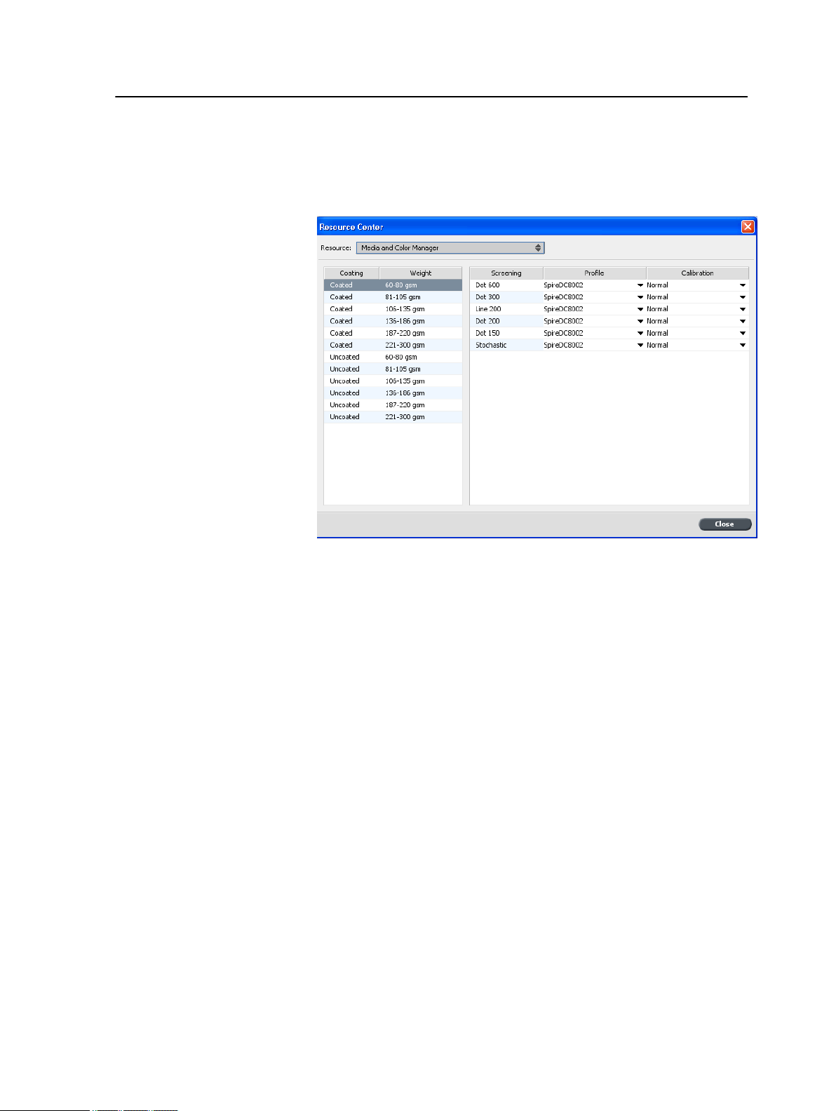
Mapping media using the Media and Color Manager tool 53
Note: The destination profile is applied to the selected media type during the
RIP.
1. In the Resource Center, select Media and Color Manager.
2. Select the media type from the list on the left.
3. On the right-hand area of the Media and Color manager
window, select the desired screen, profile, and calibration table
that you want to map to your paper stock.
4. In the Profile list, select the desired profile.
5. In the Calibration list, select the desired calibration table.
6. Click Close.
Page 62

54 Chapter 7—Managing color
Next: To apply this profile with the media type in your job, in the
job parameters window select Color > Color Flow. In the
Destination area, select Linked in the Destination Profile list.
See also:
Mapping jobs to calibration tables on page 21
Managing calibration tables
Calibrations window
You can edit and view any of the calibration look-up tables (LUTs)
that are stored on the CX print server. You can find the calibration
table information in Tools > Resource Center > Calibrations.
Calibration table list
The following calibration tables are listed:
Page 63
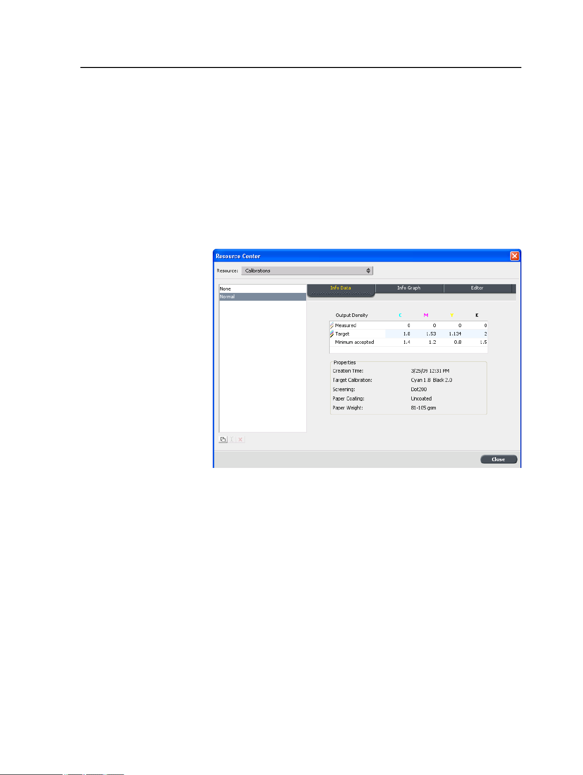
Managing calibration tables 55
●
Calibration tables created in the Calibration Wizard.
●
None: This is a default option and cannot be edited. Jobs that
have this option selected are processed and printed without
using a calibration table.
●
Normal (default table): This is a default table and cannot be
edited. If a calibration table has not been created for the media
type, Normal weight, and screening method that you are using,
the Normal calibration table is used when you process and print
your job.
Info Data
Output Density
Measured: The values that are measure from the printed
target.
Target: The expected values of the output density.
Minimum Accepted: The minimum measured value of the
output density that is accepted for correction.
Properties
The parameters that were selected when the calibration
table was created.
Page 64

56 Chapter 7—Managing color
Info Graph
During printing, the CX print server automatically replaces the
CMYK values in the RTP file with new values that compensate for
the printer’s current performance level.
Separations
The graph displays cyan, magenta, yellow, and black
separations. You can see information about each
separation by clicking the desired separation button. Or you
can view all the separations together, by clicking the button
that shows all four colors.
Output Density
The vertical axis represents the dot percentage values of
the final output data (after applying the calibration table)
that is sent to the printer.
Input %
This horizontal axis represents the dot percentage values of
the RTP file.
Adding an entry to a calibration table
You can review a calibration table to make sure that the curves are
relatively smooth and continuous. If you are not satisfied with the
results, the Edit option enables you to adjust the values of the
image in the value table.
1. From the Tools menu, select Resource Center.
Page 65

Managing spot colors 57
2. In the Resource list, select Calibrations.
3. Select the calibration table that you want to add an entry, and
click the Editor tab.
4. From the Separation list, select the desired separation to that
you want to add an entry.
The file and printer values for the separation that you selected
appear in the File Value and Printer Value lists.
5. Select a row in the value table, and click the Add (+) button.
6. In the Add Entry window, from the File Value and Printer
Value lists, select the desired values.
7. Click OK.
The value table is updated, and the calibration graph is adjusted.
8. To save your changes, click the Save button.
Managing spot colors
You can define a specific color as an RGB, CMYK, or Gray spot
color and enter a fixed CMYK target.
Page 66

58 Chapter 7—Managing color
Individual job pages can contain RGB, CMYK, and spot color
elements. A spot color is a specially mixed ink that enables you to
reproduce colors that are difficult to reproduce with CMYK inks.
The CX print server Spot Color Editor enables you to edit the
values of every spot color in the Spot color dictionary. You can edit
these values without affecting the graphics, images, or lineart
page elements.
When a spot color is converted to CMYK for digital printing, the
printout doesn’t always simulate the desired spot color. The spot
color variations feature enables you to easily edit a spot color by
selecting a more appropriate shade. The spot color variations
feature provides 37 variations, with slightly different CMYK values.
The spot color variations feature enables you to set:
●
The variation of cyan, magenta, and yellow dot percent, by
selecting variations of 1-7%. The default selection is 2%.
●
The change in the hue, by selecting variations in the cyan,
magenta, yellow, red, green, and blue axis.
●
The brightness, by increasing or reducing the K value by up to
20%.
You can assess your changes immediately in the Before and
After boxes, or you can print the entire set of variations, and
decide which best fits your requirements by examining the
printout. The edited spot color is saved in a custom dictionary.
When the CX print server identifies a spot color in a job, it first
looks for the name of the spot color in the custom dictionary and
uses the associated CMYK values. If the spot color is not found, it
looks in the PANTONE® color and HKS® color dictionaries. If the
spot color is not found in either dictionary, the CX print server uses
the CMYK values embedded in the original file.
Page 67

Adding a spot color 59
Adding a spot color
1. From the Tools menu, select Spot Color Editor.
2. In the Spot Color Editor dialog box, click the add (+) button.
3. Type the new color name as it exists in the original file.
4. Adjust the CMYK values as required.
5. Click Save.
6. Click Close.
The spot color names are case sensitive and should match the name
Note:
as it appears in the DTP software.
Page 68

60 Chapter 7—Managing color
The new color is added to the custom color dictionary.
If you created a new spot color for an RTP job, make sure you reRIP the job before printing.
Editing a spot color
1. From the Tools menu, select Spot Color Editor.
2. Do one of the following actions:
●
In the Color list, search for the desired color.
●
In the Spot color dictionary list, select the color dictionary
that contains the color you want to edit.
Note: Use the PANTONE® C dictionary if you are working in an
application such as Adobe InDesign® software.
3. Highlight the required color.
The color's CMYK values and color preview appear in the right
hand side of the Spot Color Editor window.
4. Change the CMYK values as required.
5. Click Apply.
The new color is added to the custom color dictionary.
Deleting a spot color
You can only delete spot colors from the custom color dictionary.
1. In the Spot dictionary list, select Custom Dictionary.
2. From the list of custom colors, highlight the color you wish to
delete.
3. Click remove (x) icon.
4. Click Yes to delete the color.
Printing a spot color chart
Setup and print a spot color chart in order to test the output.
In order to make sure that the spot colors will print correctly you
can send a test print of selected spot colors. According to the
results of the print out you can then make the necessary
adjustments to the spot colors using the Spot Color Editor.
Page 69

Spot color variations overview 61
Note: You can only print a spot color chart for CMYK values.
1. From the Tools menu, select Spot Color Editor.
2. Click Test Print.
3. Select a Spot color dictionary from the list and then select
the pantone patches that you want to print.
4. Click Print, and then select the following:
●
In the Screening list, select the desired screening method.
5. Click Print, to print the spot color test chart.
Spot color variations overview
A spot color is a specially mixed ink that enables you to reproduce
colors that are difficult to reproduce with CMYK inks. When a spot
color is converted to CMYK for digital printing, the printout doesn’t
always simulate the desired spot color. The spot color variations
feature enables you to easily edit a spot color by selecting a more
appropriate shade. The spot color variations feature provides 37
variations, with slightly different CMYK values.
Page 70

62 Chapter 7—Managing color
The spot color variations feature enables you to set:
●
The variation of cyan, magenta, and yellow dot percent, by
selecting variations of 1-7%. The default selection is 2%.
●
The change in the hue, by selecting variations in the cyan,
magenta, yellow, red, green, and blue axis
●
The brightness, by increasing or reducing the K value by up to
20%.
You can assess your changes immediately in the Before and After
boxes, or you can print the entire set of variations, and decide
which best fits your requirements by examining the printout.
The edited spot color is saved in a custom dictionary. When the
CX print server identifies a spot color in a job, it first looks for the
name of the spot color in the custom dictionary and uses the
associated CMYK values. If the spot color is not found, it looks in
the spot color dictionaries. If the spot color is not found in either
dictionary, the CX print server uses the CMYK values embedded
in the original file.
Selecting a spot color variation
1. From the Tools menu, select Spot Color Editor.
2. In the Color list, type the name of the spot color.
The spot color is automatically selected from the spot Color list.
3. Click the Variations button.
The Variations dialog box appears. The spot color is in the
center of the color patches and is designated as "0".
4. Click and slide the Variation steps slider to see the different
variation steps between 1 to 7 color units of the original value.
Each unit refers to a dot percentage of the original value.
5. To see the CMYK values of a color patch, roll your mouse over
the color patch.
The CMYK values appear in the bottom left corner of the
dialog box.
6. To select a variation of the spot color, click on the desired color
patch.
You can see the difference between the selected color patch
and the original spot color in the Before and After box.
Page 71

Printing a spot color variation 63
7. To select a different brightness setting for the selected color
patch, click a color patch under Brightness.
The K value of the selected color patch is increased or
decreased according to your selection.
8. Click Select.
9. Click Apply.
The spot color with the new values is added to the Custom
Dictionary.
10. Click Close.
Printing a spot color variation
Requirements: Make sure that the printer is connected and
turned on and all the queues on the CX print server are ready for
processing and printing.
1. From the Tools menu, select Spot Color Editor.
Page 72
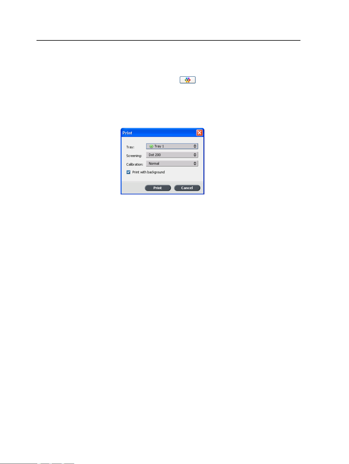
64 Chapter 7—Managing color
2. In the Color list, type the name of the spot color.
The spot color is automatically selected from the spot Color list.
3. Click the Variations button.
The Variations dialog box appears. The spot color is in the
center of the color patches and is designated as "0".
4. Select the desired color patch.
5. Click Print Variations.
6. Do the following:
●
In the Tray list, select the desired tray.
●
In the Screening list, select the desired screening method.
●
In the Calibration list, select the desired calibration table.
●
To print the variations with no background, clear the Print
with background check box.
7. Click Print.
See also:
Color tab in the Job Parameters window on page 110
Protecting specific spot colors
Using the Spot Color Editor, you can protect specific colors—for
example, official logos or company colors—to help produce color
fidelity and color consistency between devices. When you define a
specific color as an RGB, CMYK, or Gray spot color and enter a
fixed CMYK target for it, the CX print server treats it as a spot
color, protecting it accordingly.
In order to apply this your job, In the job parameters window, in the
Note:
Color tab, select Protected Colors, and then select the check box for either
the RGB, CMYK, or Gray protected colors.
Page 73
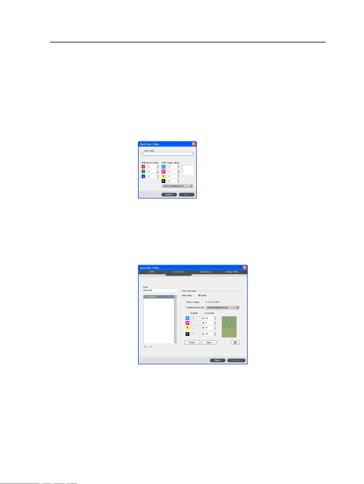
Defining an RGB color as a spot color 65
Defining an RGB color as a spot color
The RGB spot workflow applies to line work, graphic, and text
elements.
1. From the Tools menu, select Spot Color Editor.
2. In the Spot Color Editor dialog box, click the Protect RGB tab.
3. Click add (+).
4. In the Color name box, type a name for your color.
5. Type the RGB source values and the CMYK target values,
or select a spot color from the Entire Predefined List.
6. Click Save.
7. On the Protect RGB tab, select the color.
The color information appears.
8. If necessary, in the Corrected column, adjust the CMYK values.
9. Click Apply.
Defining a gray color as a spot color
The gray spot workflow applies only to line work and text elements.
1. From the Tools menu, select Spot Color Editor.
Page 74
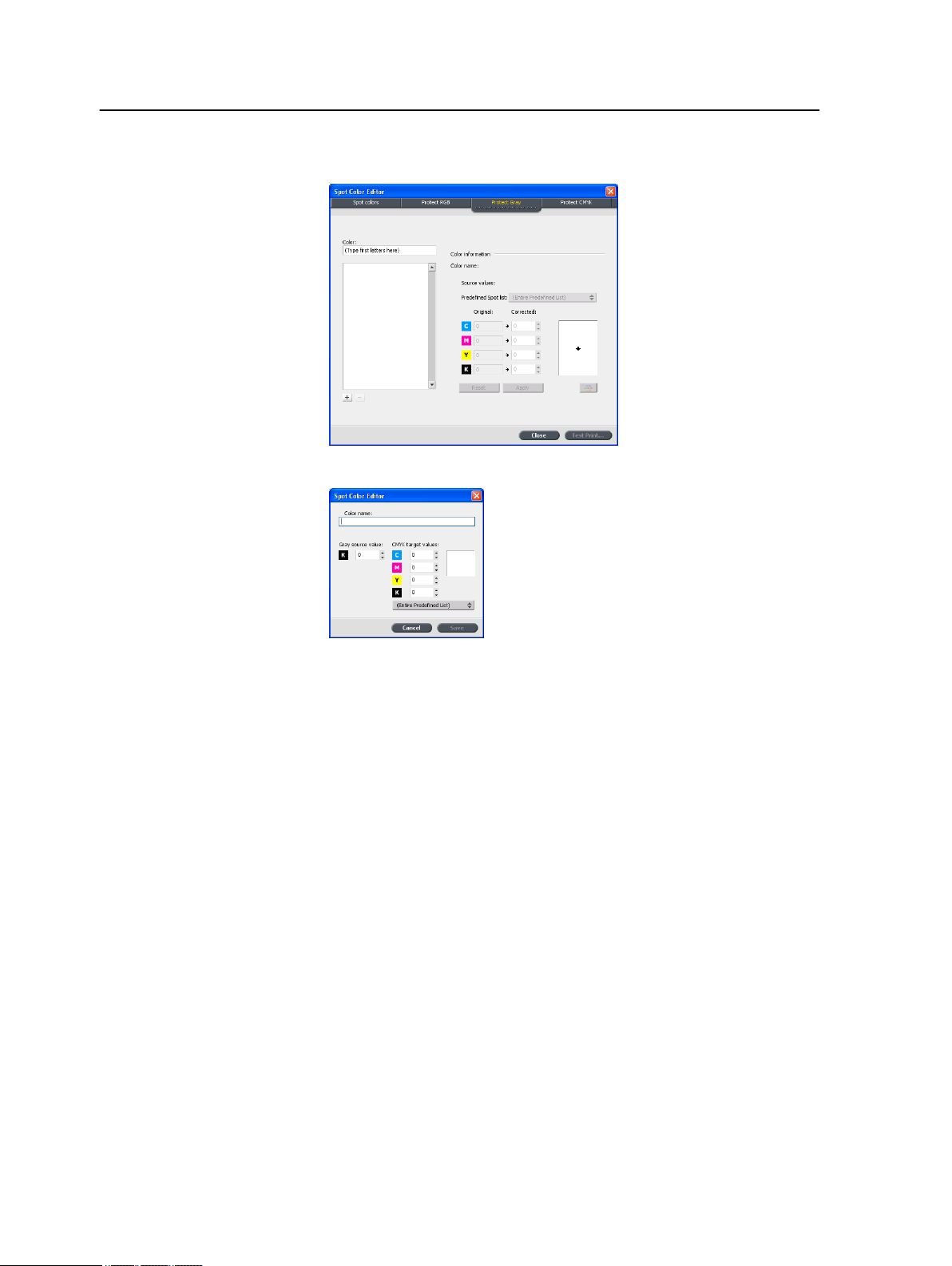
66 Chapter 7—Managing color
2. In the Spot Color Editor dialog box, click the Protect Gray tab.
3. Click add (+).
4. In the Color name box, type a name for your color.
5. Enter the Gray source value and CMYK target value, or
select a spot color from the Entire Predefined List.
6. Click Save.
7. On the Protect Gray tab, select the color.
8. If necessary, in the Corrected column, adjust the CMYK values.
9. Click Apply.
Defining a CMYK color as a spot color
The CMYK spot workflow applies only to line work and text elements.
1. From the Tools menu, select Spot Color Editor.
Page 75

Color adjustment with the Gradation Tool 67
2. In the Spot Color Editor dialog box , click the Protect CMYK
tab.
3. Click add (+).
4. In the Color name box, type a name for your color.
5. Enter the CMYK source value and CMYK target value, or
select a spot color from the Entire Predefined List.
6. Click Save.
7. On the Protect CMYK tab, select the color.
8. If necessary, in the Corrected column, adjust the CMYK values.
9. Click Apply.
Color adjustment with the Gradation Tool
Sometimes you need to perform tone corrections when you print a
job. The CX print server enables you to create a gradation table
that will correct your printed output. Changes in gradation can
include brightness, contrast, and color balance adjustments
throughout the tone range of an entire image or in specific tone
ranges.
The Gradation Tool window enables you to create and edit
gradation tables as well as visually check the effect of your
gradation tables on a specific processed job. The new gradation
tables you create are added to the Gradations list in the Color
parameter and can be applied to print jobs.
To open the Gradation Tool window:
From the Tools menu, select Gradation or click on the Gradation
Tool icon from the toolbar.
Page 76

68 Chapter 7—Managing color
Previewing a job
1. From the Tools menu, select Gradation.
2. Next to the Preview File box, click Browse.
3. Select the job that you want to preview, and then click Open.
The Original and Edited views display your job.
Creating a new gradation table
1. From the Tools menu, select Gradation.
2. In the Gradation Tool window, modify your gradation table as
required.
3. Click Save
4. In the Table name box, type the name of the new gradation table.
5. Click OK.
The gradation table is saved and added to the Gradation Table
list and to the Color Adjustments tab in the job parameters window.
.
Page 77
Editing a gradation table 69
Editing a gradation table
When you open the Gradation Tool, the default gradation table,
DefaultGradTable, is selected in the Gradation Table list, and is
displayed in the graph. This table serves as a baseline and
consists of a 45° gradation curve, with Brightness and Contrast set
to 0, and Contrast Center set to 50. All of the color separations are
selected.
The Gradation Table list includes four other predefined gradation
tables:
●
Cool: Blue tones appear clearer
●
Lively: Increases the color saturation
●
Saturated: Increases the strength (chroma or purity)
●
Sharp: Increases the contrast
●
Warm: Sets the hues in the low densities to a bright reddish color
Gradation tables that you create or edit also appear in the
Gradation Table list. When you select a gradation table, the
predefined settings are immediately applied to the processed job
that you are working with. The Separations buttons enable you to
select one, all, or any combination of separations to edit for a
specific gradation table. Selecting a specific separation enables
you to change the color balance for a specific tonal orange. When
you open the Gradations Tool window, all of the separations are
selected.
When you change gradation table definitions in the Gradation tool and
Note:
click Refresh, you will notice that the changes have affected the image in its
entirety. However, despite what you see in the Edited view, changes made to
the gradation tables do not affect spot colors.
1. From the Tools menu, select Gradation.
2. To edit the separations, do one of the following:
●
Click the All Colors button
to edit all the separations
simultaneously.
●
Click the individual separations you wish to edit—for
example, select the cyan separation only.
3. Click the curve in the graph to add a point, and then drag the
point to modify the separation.
The value appears in the Input or Output boxes.
4. To view gradation changes in your job, click Refresh.
Changes are automatically applied to the displayed image in
the After view.
Page 78
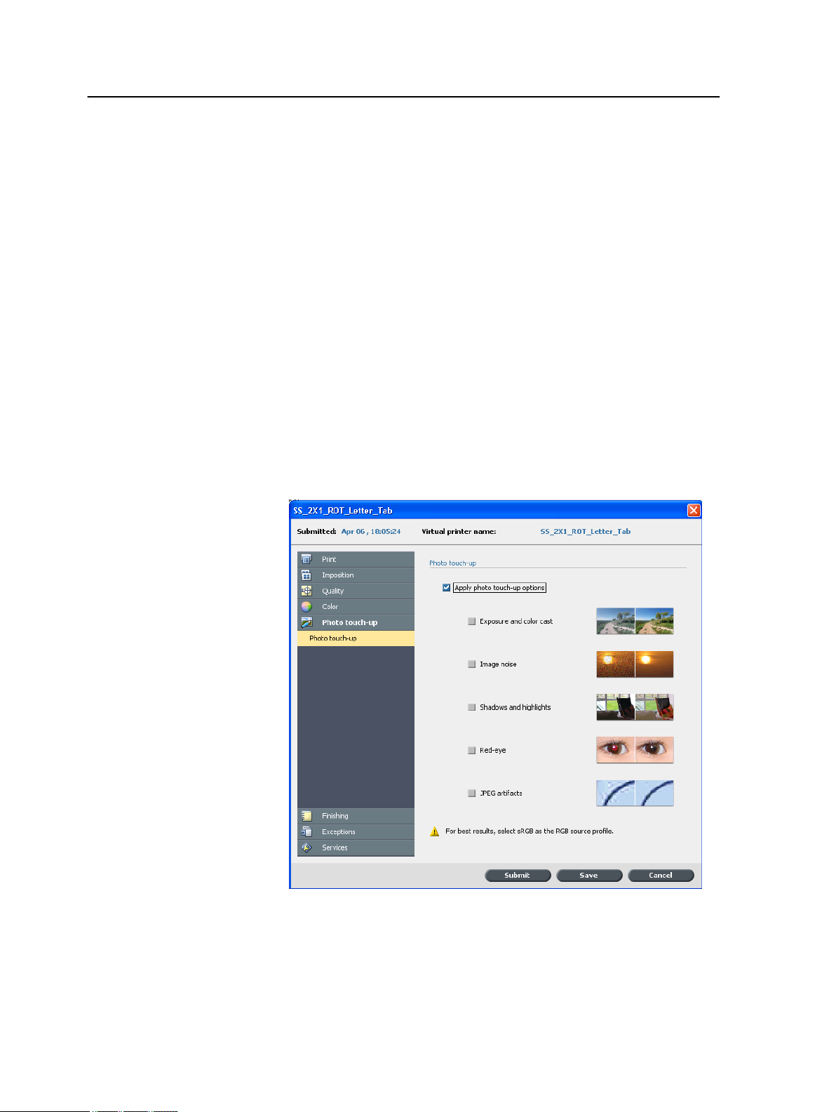
70 Chapter 7—Managing color
5. To remove a point on the curve, select the point and then click
Remove.
6. To reset the gradation curve to a 45° curve, click Reset.
7. To revert to the original gradation settings, click Revert.
8. To remove the last change you made to the gradation graph,
click Undo.
Correcting an image using Photo Touch-up
The photo touch-up options correct common flaws found in JPEG
RGB format images in PDF files.
1. Open the Job Parameters window for the desired job.
2. In the Photo Touch-Up tab, select Photo Touch-Up.
3. Select Apply photo touch-up options.
4. Select one or more photo touch-up options.
The image is corrected according to the selected options as
follows:
●
Exposure and color cast:
Page 79

Correcting an image using Photo Touch-up 71
Correct underexposure, overexposure, and minor color-cast
problems in photos.
●
Image noise:
Reduce noise (such as granularity caused by high ISO
settings) in a photo.
●
Shadows and highlights:
Bring out details in the dark and light areas of a photo.
●
Red-eye:
Remove the red-eye effect in photos taken with a flash.
●
JPEG artifacts
Remove JPEG artifacts often found in low-quality or highly
compressed JPEG files, particularly in gradient and vignette
areas and around the edges of objects.
5. Select Submit.
The job is sent to the Process Queue.
Page 80

72 Chapter 7—Managing color
Page 81

Production workflows
8
Print using imposition
Imposition overview
Imposition is the process of positioning page images on a virtual
sheet of paper so that when a printer or digital printing press prints
the sheet, the page images will be in the right order. It is part of the
process of producing finished documents.
In addition to page images, you can add various marks to the
sheets to aid the production process. These marks show where the
paper should be folded or trimmed.
Imposition does not affect the content of the individual page but
rather affects only the placement of the page images on a press
sheet. Imposition is a combination of content and layout. The
content is the pages that should be printed, and the layout is the
location of the page on the sheet, along with the page’s printing
marks, crop marks and fold marks.
See also:
Imposition tab in the Job Parameters window on page 104
Imposition methods
The CX print server provides the following imposition methods:
Step and repeat: The step-and-repeat method is the most efficient
one when you want to print multiple copies of the same image and
fill each sheet to capacity—for example, many business cards on
one sheet.
Page 82

74 Chapter 8—Production workflows
Step and continue: The step-and-continue method enables you
to place different pages of a job on one sheet so that the sheet is
filled to capacity.
Cut and stack: The cut-and-stack method is used to print, cut,
and stack pages while preserving a certain order. When the cut
stacks are piled one on top of the other, the entire job ends up in
the desired order. The cut-and-stack method is useful primarily for
high-volume variable information jobs.
Saddle stitch: The saddle-stitch method prints pages in a manner
that is suited for saddle-stitch binding. With this binding method,
sheets are folded, inserted one inside another, and then stitched
or stapled along the spine, such as in a brochure or magazine.
Perfect bound: The perfect-bound method prints pages in a
manner that is suited for perfect binding. Perfect binding is a bookfinishing technique in which the folded sheets are gathered in
order and clamped into place. A saw roughens the spine edge of
the gathered pages. Glue is then applied to the spine, and the
cover of the book is affixed to the glued spine. This method is
used for most books.
Previewing an imposition layout
The Preview window enables you to view your imposition layout
and settings.
Requirements:
An imposition method must be selected.
Page 83

Imposition layout Preview window 75
You can open the Preview window at any time and keep it open to
check your imposition settings as you select them. The Preview
window dynamically reflects any changes that you make.
1. Open the Job Parameters window for the desired job.
2. Click the Imposition tab, and make sure that an imposition
method has been selected.
3. Click the Preview button.
The Preview window appears.
Imposition layout Preview window
Preview window buttons
Front
Back
Navigation
buttons
Navigation box
Gray arrows
Click to view the front pages.
Click to view the back pages.
Click the navigation arrows to move between
sheets.
Jump to a specific sheet by typing a number in
the navigation box.
Page image
Indicate the direction of the pages on the sheet.
Page numbers
Indicate the numbered sequence of the pages.
Page 84

76 Chapter 8—Production workflows
Imposition Conflict
If any parameters conflict, Imposition Conflict appears in red in
the Preview window and also on the Imposition tab.
Conflict
indications
Printing a business card job
Requirements:
This example assumes that your job contains one-sided business
cards that are 50 mm × 90 mm (1.96 in. × 3.45 in.), imposed on A3
paper.
This example demonstrates how to use the Step & Repeat
imposition method to print business cards. With the Step &
Repeat method, you can print multiple copies of the same image
on one large sheet.
A red border along the edge of the page
indicates where the conflict exists.
●
If the red border appears along the upper
and lower edges of the page, a conflict
exists in the height value.
●
If the red border appears along the left and
right edges of the page, a conflict exists in
the width value.
Problematic values appear in red.
1. Click the suspend button to suspend the Process queue.
2. From the File menu, select Import.
Page 85
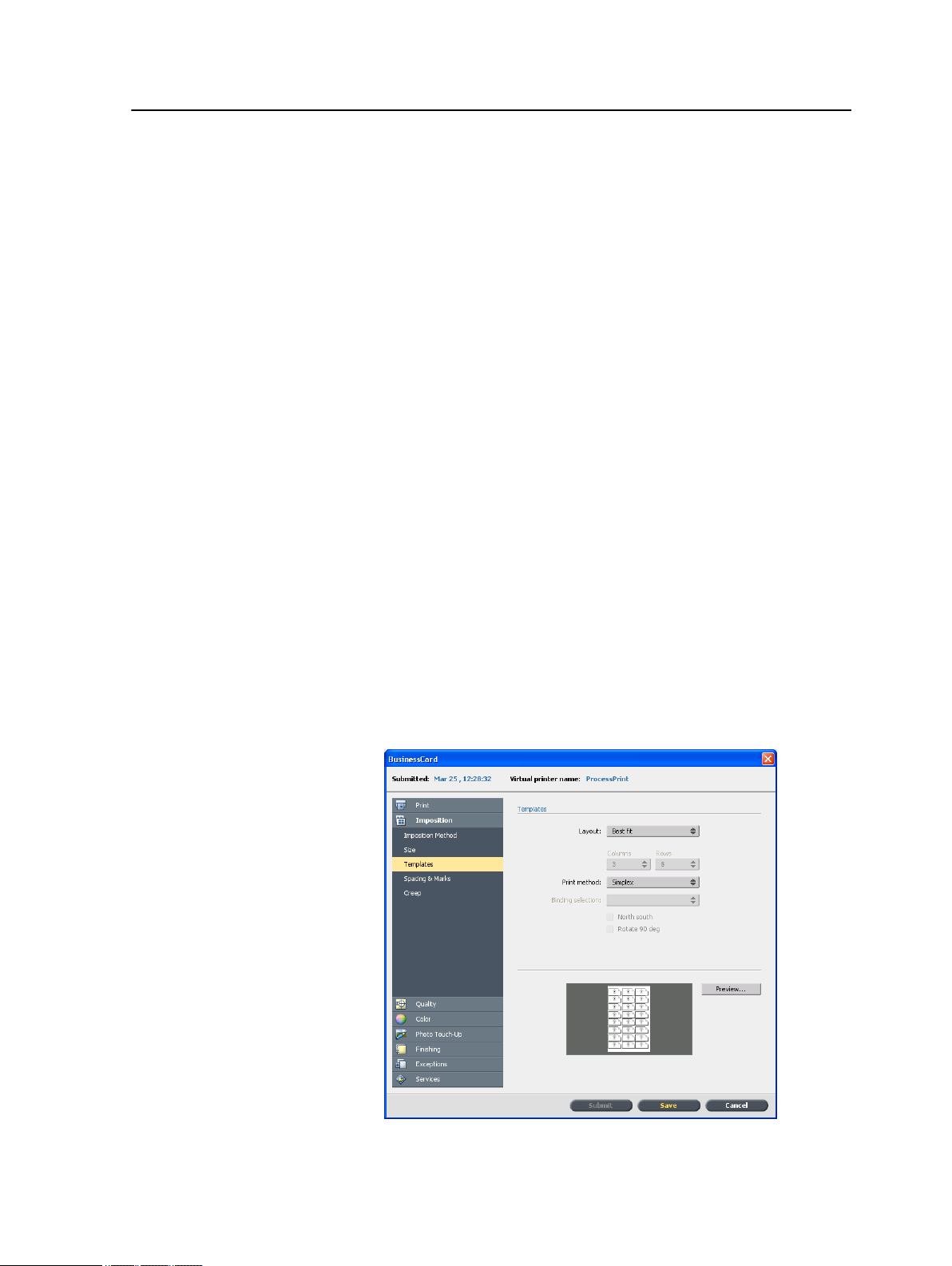
Print using imposition 77
3. Import your business card file to the ProcessPrint virtual printer.
The file is imported to the Process queue with a Waiting status.
4. In the suspended Process queue, double-click the business
card file.
The Job Parameters window appears.
5. In the Job Parameters window, under Print, select the Paper
Stock parameter.
6. In the Paper size list, select 11 x 17.
7. Click the Imposition tab.
8. In the Imposition Method list, select Step & Repeat.
9. Select the Size parameter, and set the values as follows:
a. For Trim Size, select Custom
b. For H, type 1.96 inches or 50 mm
c. For W, type 3.54 inches or 90 mm
A preview of the layout is displayed below.
10. For Trim orientation, make sure that the Landscape option
is selected. To change the trim orientation, in the Job
Parameters window, select Print and then select Layout.
Select the desired orientation.
11. Select the Templates parameter, and set the values as follows:
a. In the Layout list, select Best Fit. The CX print server
determines how many business cards can fit on each sheet.
The CX print server calculates the best fit.
b. For Print Method, make sure Simplex is selected, since
your business cards are one-sided.
Page 86

78 Chapter 8—Production workflows
12. Click the Preview button to preview the layout.
The Preview window appears, displaying a schematic
representation of your imposition layout. The layout of three
columns by eight rows appears with no imposition conflict.
13. Leave the Preview window open, and, if necessary, drag it to
the right.
14. Select the Spacing & Marks parameter.
15. In the Marks list, select Crop marks.
The crop marks automatically appear in the Preview window
and the Margins size is automatically increased to
accommodate the crop marks.
16. In the Gutter box, type 0.2 inches or 5 mm.
As soon as you change the value for the Gutter size, the
imposition layout in the Preview window automatically
changes. The CX print server calculates that to accommodate
a gutter of 0.2 inches or 5 mm, a layout of three columns by
seven rows will best fit on each sheet.
17. Check the Preview window. No imposition conflicts appear.
18. In the Job Parameters window, click Save.
19. Release the suspended Process queue.
Your business cards are processed and printed according to
the imposition settings.
Printing a saddle stitch job
Requirements:
This example assumes the following:
●
Your job is an eight-page brochure, with a custom trim size of
5.27 by 3.34 inches or 134 by 85 mm.
●
Tabloid or A3 paper is loaded in the printer.
This example demonstrates how to use the Saddle Stitch
imposition method to print two sets of the same job on one press
sheet to save paper and production time.
1. In the Storage area, double-click your job.
2. In the Job Parameters window, click the Imposition tab.
3. In the Method list, select Saddle stitch.
4. In the Sets per sheet list, select 2 to print two sets of your
imposed job on one press sheet.
5. Click Spacing & Marks.
6. In the Marks list, select Crop marks.
7. In the Bleed box, type 0.118 inches or 3 mm.
Page 87

Imposition Template Builder Tool 79
8. Click the Preview button.
A schematic representation of the imposition layout appears.
Note: When you print your job, a space of 0.39 inches or 10 mm is
automatically added between the two sets on the sheet.
9. Close the Preview window.
10. Click Submit.
Your job is processed and printed according to the imposition
settings for two sets per sheet. You have used most of the
sheet's space and saved on paper. You can also easily cut and
staple the two brochures.
Imposition Template Builder Tool
Imposition Template Builder overview
The Imposition Template Builder enables you to save imposition
layouts and reuse them for different jobs, without needing to define
the same layout repeatedly. The Imposition Template Builder also
allows you to create and save templates with special layouts that
cannot be created on the Imposition tab alone.
After you save a template, you can apply it to a specific job.
All saved templates appear on the Imposition tab. After you
select an imposition method, the related templates appear in the
Template parameters, in the Layout list. For example, if you
created a Step & Continue template, the template appears in the
Layout list only when you select the Step & Continue imposition
method.
Some templates appear under more than one imposition method.
Method selected on
Imposition tab:
Step & Repeat Step & Repeat, Cut & Stack
Step & Continue Step & Continue
Saddle Stitch Saddle Stitch, Perfect Bound
Perfect Bound Saddle Stitch, Perfect Bound
Template layout type in the layout list:
Creating an imposition template
Page 88

80 Chapter 8—Production workflows
On the CX print server, you can use the Imposition Template
Builder to create templates for similar types of jobs that have the
following imposition settings in common:
●
Imposition method
●
Columns and rows
●
Simplex/duplex
●
Binding
For example, if you want to create an imposition template for A4sized brochures printed on A3 paper, you could create a template,
called “A4Brochure”, and select the following settings:
●
Imposition method: Saddle Stitch
●
Columns: 2
●
Rows: 1
●
Type: Duplex (selected by default)
●
Binding: Left
You would define all the other imposition settings—for example,
Trim Size, Bleed, Margin, Gutters,Paper Type, and Sheet Size—
on the Imposition tab.
1. From the Tools menu, select Imposition Template Builder.
2. From the Method list, select an imposition method.
3. Click the New (+) button.
4. Type the name of the new template, and press Enter.
5. In the Layout area, type the number of columns and number
of rows that you need.
The imposition method that you select determines the number
of columns and rows that you can enter. For Saddle Stitch
and Perfect Bound, you can place up to 64 pages on one
sheet (8 × 8). For Step & Repeat and Step & Continue, you
can place up to 625 pages on one sheet (25 × 25).
6. Under Type, select Simplex or Duplex.
7. Under Orientation, select Portrait or Landscape.
The Orientation setting in the Imposition Template Builder is for
Note:
display purposes only. This parameter is not saved in the template. (You set
job orientation on the Imposition tab, under Size).
8. From the Binding list, select the appropriate binding method.
Binding is available only when Saddle Stitch and Perfect Bound
Note:
imposition methods are selected.
9. Click Save.
Imposition template viewer window
As you create or modify a template, you can see your template in
the template viewer. As you select parameters, the template
viewer dynamically changes to reflect your selections.
Page 89

Editing an imposition template 81
Buttons
Notes:
●
When Simplex is selected, only the Front view is available.
●
Sheet size is set on the Imposition tab. The sheet size that appears in
the template viewer is dynamic. It changes to accommodate the
parameters that you choose.
Front
Back
Both
Click to view the front pages.
Click to view the back pages.
Click to view both the front and back pages
simultaneously.
Editing an imposition template
Rotating a page 180 degrees
The template viewer enables you to rotate one or more pages and
change the location of pages on the sheet.
The gray arrow on each page indicates the top of the page. The
page number is indicated by the number that appears on each page.
1. Make sure the Apply changes to front and back check box
is clear.
2. Select the desired page.
To select multiple consecutive pages, click the first page, press and
Note:
hold Shift, and then click the last page. Select multiple non-consecutive
pages by pressing and holding Ctrl as you click each page.
3. Click the Rotate 180 button.
Page 90

82 Chapter 8—Production workflows
Rotating both the front and back sides of a page 180 degrees
1. Select the desired page.
2. Select the Apply changes to front and back check box.
3. Click the Rotate 180 button.
Changing the position of a specific page on a press sheet
You can change the location of a page on a sheet as needed.
Changing the location of a page is often necessary when the Step
& Continue imposition method is selected.
1. Click the target location that you want to move the page to—
for example, click page 10 if you want to place a different page
in that location.
The target location turns blue when selected.
2. Click the Page Number box, and type the number of the page
that you want to move to the target location. For example, you
would type 5 to place page 5 in the location of page 10.
3. Press Enter.
The page moves to its new location.
Page 91

Simulating a job with your template 83
Note: The page number that was previously in the target location is not
automatically moved to another location. To retain this page, manually move
this page to a new location.
If you have a duplex job and the Apply changes to front and back check
box is selected, the page number for the back side of the page also
changes. Using the example above, page 6 would be on the back side of
page 5.
Simulating a job with your template
You can simulate how jobs from the Storage window will look if
you apply an imposition template to them.
Note: The imposition template parameters are not actually applied to the job
—you are viewing only a simulation of how the job would look if this template
were selected on the Imposition tab.
1. In the Imposition Template Builder window, click the Simulate
button.
2. Click Browse.
3. Select a job, and then click Select.
The parameters of the job (Sheet Size, Trim Size, Trim
Orientation, Sets per sheet, Bleed Size, Rotate 90, Crop
Marks, and Fold Marks) appear with their values in the
Simulate Imposition window.
Both RTP and non-RTP jobs are available for simulation.
Note:
4. Change the parameters as desired.
5. Click View Simulated Job.
The Preview window appears. A simulation of the job is displayed
with the current imposition template applied.
Print with exceptions
Adding exceptions to your job
Exceptions are used when you want to use different media types
for special exceptions within a job, or add inserts.
Note:
1. Open the Job Parameters window of your job.
2. Click Exceptions.
Page 92

84 Chapter 8—Production workflows
3. In the Type list, select the pages in your job in which the media
type will be different.
4. Depending on the option you selected in the Type list, perform
one of the following steps:
●
For Page range, type the page range in the box.
●
For Front cover or Back cover, select the Duplex check
box to print the first two (or last two) pages of the job as the
cover page (back cover).
Note: If the imposition type is Saddle Stitch, select Cover to print both
a front and back cover page on a different media type. Select Middle
sheet to print the internal sheets on a different media type.
●
For Inserts, select Before or After and type the page
number that will precede or follow the insert. Then, in the
Quantity box, type the total number of inserts you want to
add.
5. Click Advanced Options.
6. In the Destination profile list, select a destination profile. You
can select per page or a range of pages.
7. Under Image Position, do one of the following:
●
To have the image position be the same as the rest of the
job, make sure the Same as job check box is selected.
●
To shift the image on the second side of the sheet
according to the image shift on the first side of the sheet,
select the Same on Both Sides check box.
8. Click Save.
9. Click Apply.
10. Click Save or Submit.
Deleting exceptions from your job
1. Open the Job Parameters window of your job.
2. Click Exceptions.
3. Select the exception that you want to delete.
4. Click Remove.
Dynamic page exceptions and setpagedevice commands
The dynamic page exceptions is only available with the Professional
Note:
Power Pack.
A setpagedevice command is a standard PostScript command that is
embedded in a file and enables you to print a complex job that
contains paper of varying size, coating, weight, and so forth. Such
commands indicate that the printer must switch media during the
printing of a job. When a job is RIPed, the CX print server
Page 93

Printing dynamic page exceptions 85
identifies the setpagedevice commands and maps them to the
selected types of paper. The printer then uses those types of
paper for the job.
Page exceptions and inserts that include setpagedevice commands
are called dynamic page exceptions. The CX print server supports
dynamic page exceptions for the following file formats:
●
PostScript
●
VPS
●
PDF
Printing dynamic page exceptions
Requirements:
A file with embedded setpagedevice commands.
1. From the Tools menu, select Resource Center.
2. In the Resource list, select Virtual Printers and either create
a new virtual printer or edit an existing one.
3. Select the Support dynamic page exceptions check box.
4. Click Edit to open the Job Parameters window.
5. Under Exceptions, select the paper stock for each exception
or insert.
6. Import the file to the CX print server via the dedicated virtual
printer, and submit the job.
If the virtual printer is based on either a ProcessStore Process or
Note:
SpoolStore Store virtual printer, you can perform a preflight check before the
job is printed.
The job is RIPed, and the setpagedevice commands are identified
and mapped to the selected types of paper.
Important:
●
Virtual printers that support dynamic page exceptions do not support
regular page exceptions and imposition.
●
A virtual printer that is dedicated to dynamic page exceptions can print
only jobs with dynamic page exceptions. Do not print other types of jobs
via that virtual printer.
●
You can perform a preflight check on SPD commands. Make sure the
virtual printer has support dyynamic page exceptions selected.
Page 94

86 Chapter 8—Production workflows
Print tabs using the Creo Color Server Tabs plugin for Acrobat
Tabs plug-in overview
The Tabs plug-in is a Creo plug-in, developed for use with Adobe
Acrobat. The Tabs plug-in enables you to create and place tabs in
your unprocessed job (PDF or PostScript), manage the tab and
text attributes, and save a set of attributes for future use.
Tabs plug-in window
Tabs
Text attributes - tabs
Size
The size of the tabbed sheet. By
default, the tab size for letter jobs is set
at 9x11, and for A4 jobs to A4+.
Type
The number and type of tabs that you
can select.
Note: If you want your tabs to be reversed—
that is for the lowest tab to be the first one—
select one of the reverse tab options.
Orientation
Page 95
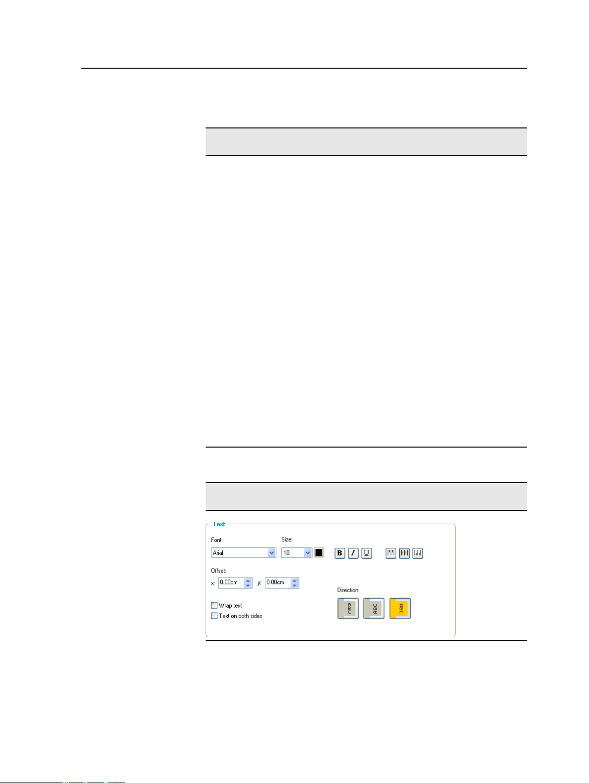
Print tabs using the Creo Color Server Tabs plug-in for Acrobat 87
Text attributes - tabs
Orientation of the tab.
Top Offset
The value for the distance between the
upper edge of the paper and the upper
edge of the uppermost tab.
Note: The units in the Tabs plug-in are set in
the Acrobat Preferences dialog box.
Bottom Offset
The value for the distance between the
lower edge of the paper and the lower
edge of the lowest tab.
Text
Length
The length of the tab.
Width
The width of the tab.
Text attributes - text
Font
The font for the tab text.
Size
Page 96

88 Chapter 8—Production workflows
Text attributes - text
The font size for the tab text.
Color
The color of the tab text.
Bold
Bolds the tab text.
Italic
Makes the tab text italic.
Underline
Underlines the tab text.
Alignment
The alignment of the tab, according to
the orientation of the tab. The
orientation that you select determines
the alignment buttons that are displayed.
●
●
●
●
●
●
Align Left Portrait
Align Center Portrait
Align Right Portrait
Align Left Landscape
Align Center Landscape
Align Right Landscape
Offset
The value that adjusts the offset of text
on the tab. The x value moves the text
horizontally. The y value moves the text
vertically.
Wrap text
Page 97
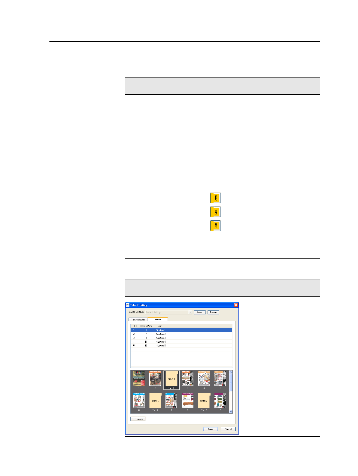
Print tabs using the Creo Color Server Tabs plug-in for Acrobat 89
Text attributes - text
Automatically wraps the text onto the
following ine when the entire text does
not fit on one line.
Text on both sides
The same text appears on both sides of
the tab.
Direction
Direction of the text.
●
●
●
Note: The Direction options are available
only for portrait jobs.
Vertical
Counter-clockwise
Clockwise
Content
Page 98

90 Chapter 8—Production workflows
Content
#
Before Page
Text
Thumbnails
area
Remove
Saved Settings
The tab number.
The page number that the tab precedes.
The text that appears on the tab.
A thumbnail view of the job with page
numbers and tabs indicated.
Removes the selected page or tab.
Settings
Lists the saved settings files.
Creating tabs
Save
Delete
Requirements:
You can only create tabs in a PDF or PostScript file.
1. In the Storage window, right-click your unprocessed job, and
select Job Preview&Editor.
The job opens in Acrobat software.
2. From the Plug-Ins menu, select Tabs Printing.
The Tabs Printing window opens, displaying the Text
Attributes tab.
Saves the currently selected settings in a file.
This settings file can be applied to other PDF
or PostScript files.
Deletes the selected settings file.
Page 99

Print tabs using the Creo Color Server Tabs plug-in for Acrobat 91
3. In the Tabs area, set the tab attributes.
4. (Optional) In the Text area, set the attributes of the text on the
tabs.
5. Click the Content tab.
6. In the Before page column, click the first cell and type the
number of the page that you want the tab to precede.
Page 100

92 Chapter 8—Production workflows
7. In the Text column, type the text for the tab.
The tab appears in the thumbnail area.
Managing tabs
8. To add more tabs, repeat steps 6 and 7.
9. Click Apply to apply the tab settings to your document.
The Tabs Printing window closes, and the tabs that you added
become part of the document.
10. From the Acrobat File menu, select Save, and then close
Acrobat.
11. Process and print the job.
Changing the location of a tab
1. In the Storage window, right-click your unprocessed job, and
select Job Preview&Editor.
The job opens in Acrobat software.
2. From the Plug-Ins menu, select Tabs Printing.
The Tabs Printing window opens, displaying the Text Attributes
Text Attributes tab.
3. Click the Content Content tab.
 Loading...