

Page 1

Xerox 6030/6050 Wide Forma
t
Printer User Guide
701P46753
Version 3.0
January 2006
Page 2

Xerox Corporation
Global Knowledge & Language Services
800 Phillips Road Bldg. 845-17S
Webster, NY 14580
Copyright © 2006 Xerox Corporation. All rights reserved.
Printed in the United States of America.
Copyright protection claimed includes all forms and matters of copy-
righted material and information now allowed by statutory or judicial
law or hereinafter granted, including without limitation, material gener-
ated from the software programs that are displayed on the screen such
as styles, templates, icons, screen displays, looks, etc.
AIX is a trademark of International Business Machines Corporation.
AutoCAD is a registered trademark of AutoDesk, Inc.
HDI is an acronym for Heidi® Device Interface. Heidi is a registered
trademark of AutoDesk, Inc.
HP-GL is a trademark of Hewlett-Packard Company.
Macintosh and AppleTalk are registered trademarks of Apple Com-
puter, Inc.
Microsoft® Windows, Windows 95/98, Windows Me, Windows NT®,
Windows® XP, Windows® 2000, Windows® Server 2003 are trade-
marks of Microsoft Corporation.
Internet Explorer is a copyright protected program of Microsoft Corpo-
ration.
Netscape is a registered trademark of Netscape Communications Cor-
poration.
Solaris and SunOS are registered trademarks of Sun Microsystems, Inc.
UNIX is a registered trademark of Open Group Company Limited
XEROX®, The Document Company®, the digital X®, Xerox
6030/6050 Wide Format Printer, and Versatec are the trademarks of or
licensed to XEROX CORPORATION.
Page 3

Preface
Thank you for using the Xerox 6030/6050 Wide Format Copier/Printer User Guide
(hereinafter known as 6030/6050 Wide Format).
This User Guide describes the basic operations and the detailed functions of the Xerox
6030/6050 Wide Format Copier, Printer, and integrated Scanner. It also includes usage
precautions, safety, replenishing toner, replacing paper, troubleshooting, and other
general instructions.
The explanations provided in this User Guide assume that the user has a basic
knowledge of operating the computer and network configuration in use. Refer to the
manuals supplied with the computer, Windows related documentation, and the manuals
supplied with the network system for details on computer and network operations.
Page 4

Conventions
This User Guide uses the following symbols and conventions:
< > key Indicates the keys on the keyboard.
Press the <Enter> key.
[ ] Indicates the menus and display items on the screens.
Select either the [On] or [Off] buttons to display [Job
Name], [Owner], and [Reason] in that order.
" " Indicates areas of reference within this User Guide.
Also indicates messages.
Refer to
A message stating "Additional Port Information Required. The
"3.2 Print Services".
Device could not be identified
Indicates important information which you should read.
Indicates additional information on operations or features.
Indicates reference sources.
Indicates examples.
"
appears.
Page 5
Safety Notes
Read these safety notes carefully before using this product to ensure you operate the equipment safely.
Your Xerox product and recommended supplies have been designed and tested to meet strict safety
requirements. These include safety agency approval, and compliance with established environmental
standards. Please read the following instructions carefully before operating the product and refer to
them as needed to ensure the continued safe operation of your product.
The safety and environment testing and performance of this product have been verified using Xerox
materials only.
WARNING: Any unauthorized alteration, which may include the addition of new
functions or connection of external devices, may affect the product
certification. Please contact your authorized local dealer for more
information
WARNING MARKINGS
Warning Markings
All warning instructions marked on or supplied with the product should be followed.
Warning This WARNING alerts user to areas of the product where there is the
possibility of personal injury.
Warning This WARNING alerts users to areas of the product where there are
heated surfaces, which should not be touched.
WARNING
This product is certified manufactured and tested in compliance with strict safety
and radio frequency interference regulations. Any unauthorized alteration which,
includes the addition of new functions or the connection of external devices, may
affect this certification. Please contact your local XEROX Limited representative
for a list of approved accessories.
WARNING
In order to allow this equipment to operate in proximity to Industrial, Scientific, and
Medical (ISM) equipment, the external radiation from the ISM equipment may have
to be limited or special mitigation measures taken.
Page 6

WARNING
Shielded cables must be used with this equipment to maintain compliance with
Council Directive 89/336/EEC.
The Electricity at Work Regulation (in England and Wales) UK ONLY
Electricity at Work Regulations
The Electricity at Work Regulation 1989 came into force in England and Wales on the 1 April 1990.
This 1989 Regulation places a duty on all employers and self-employed persons to ensure the electrical
system in their premises are constructed, maintained and operated in such a manner as to prevent, so far
as reasonably practical, danger. This includes ensuring all electrical equipment connected to such elec-
trical systems are safely constructed, maintained and operated. All Xerox equipment have been
designed to exacting safety standards. They have all undergone a variety of stringent safety tests includ-
ing earth bond, insulation resistance and electrical strength tests. Xerox manufacturing plants have been
awarded ISO 9000 quality certification and are subject to regular audits by the British Standards Institu-
tion or equivalent national standards body. Xerox equipment which has been properly and regularly ser-
viced and maintained should not have to undergo additional specific safety tests pursuant to the 1989
Regulation. Customers wishing to complete safety testing should contact Xerox for advice prior to any
test implementation. Xerox equipment should, however, be properly and regularly serviced and main-
tained at all times.
QUESTION: What is the Electricity at Work Regulation?
ANSWER: The Electricity at Work Regulation 1989 came into force in England and Wales on the
1 April 1990. This 1989 Regulation places a duty on all employers and self-employed persons to ensure
the electrical systems in their premises are constructed, maintained and operated in such a manner as to
prevent, so far as reasonably practicable, danger. This includes ensuring all electrical products con-
nected to such electrical systems are safely constructed, maintained and operated.
QUESTION: Does Xerox comply with the Electricity at Work Regulation?
ANSWER: The regulation places a duty on all employers and self-employed persons to ensure the elec-
trical systems in their premises are, effectively safe. The regulation does not impose on, amongst others,
manufacturers or suppliers of such electrical systems. However, rest assured that all Xerox equipment
which Xerox and its authorized distributors supplies to customers, conform with all the relevant safety
legislation and standards.
QUESTION: Is Xerox equipment safe?
ANSWER: All Xerox equipment supplied by Xerox and their authorized distributors conform to all
relevant safety legislation and standards.
Page 7

QUESTION: Is the Xerox equipment in my premises safe?
ANSWER: All Xerox equipment supplied by Xerox and its authorized distributors conform to all rele-
vant safety legislation and standards. However, like all electrical equipment, they have to be regularly
serviced and maintained by competent persons. Xerox Customer Service Engineers ensure Xerox equip-
ment is serviced and maintained to exacting Xerox safety standards. If you would like your Xerox
equipment to be serviced and maintained to such high standards, please contact your local Xerox Cus-
tomer Service Organization. They will be pleased to assist you.
QUESTION: Does the Xerox equipment in my premises comply with the Electricity at Work Regula-
tions?
ANSWER: All employers and self-employed persons must ensure that the electrical systems in their
premises are safe. This will include ensuring Xerox equipment in such premises is safe. Xerox Product
Safety function has prepared a guide which contains a list of tests which may be completed by your
Xerox Customer Service Organization.
THESE TESTS MUST BE CARRIED OUT ONLY BY PERSONS WHO POSSESS THE RELEVANT SKILL,
KNOWLEDGE AND EXPERIENCE TO CARRY OUT SUCH TESTS.
Please contact the Xerox Customer Service Organization for further information.
THE USE OF INAPPROPRIATE TEST PROCEDURES AND TEST EQUIPMENT MAY PROVIDE MISLEADING
RESULTS AND MAY CAUSE DEATH, PERSONAL INJURY AND/OR DAMAGE TO PROPERTY.
QUESTION: I would like to carry out my own safety tests on the Xerox equipment in my premises.
ANSWER: You may, of course, request such tests as you deem necessary to satisfy yourself that your
Xerox equipment is safe. Your Xerox Customer Support will be pleased to advise you on such
testing.
QUESTION: I require records of all tests
ANSWER: After safety testing, your Xerox Customer Service Engineer will provide you with a certifi-
cate which details the results of all tests completed. In the event of any defect being noted, the Xerox
equipment will be switched off and disconnected from the supply until the defect has been corrected.
You will be advised of such action to enable such defects to be corrected.
PLEASE NOTE: YOU MUST ENSURE THAT YOUR XEROX EQUIPMENT IS SAFE AT ALL TIMES
Electrical Supply
This product shall be operated from the type of electrical supply indicted on the
product 's data plate label. If you are not sure that your electrical supply meets the
requirements, please consult your local power company for advice.
Page 8

WARNING
This product is supplied with a plug that has a protective earth pin. This plug will fit
only into an earthed electrical outlet. This is a safety feature. To avoid risk of electric shock, contact your electrician to replace the electrical outlet if you are unable
to insert the plug into it. Never use an earthed adapter plug to connect the product
to an electrical outlet that lacks an earth connection terminal.
This product must be connected to a protective earth circuit.
Operator Accessible Areas
This equipment has been designed to restrict operator access to safe areas only.
Operator access to hazardous areas is restricted with covers or guards, which
would require a tool to remove. Never remove these covers or guards.
Maintenance
Any operator product maintenance procedures will be described in the user documentation supplied with the product. Do not to carry out any maintenance on this
product, which is not described in the customer documentation.
Cleaning Your Product
Before cleaning this product, unplug the product from the electrical outlet. Always
use materials specifically designated for this product; the use of other materials
may result in poor performance and may create a hazardous situation. Do not use
aerosol cleaners; they may be explosive and flammable under certain circumstances.
Page 9

WARNING - Electrical Safety Information
CAUTION
Ensure that the power connection for your machine satisfies these requirements
• Use only the power cord supplied with this equipment.
• The socket outlet shall be installed near the equipment and shall be easily accessible.
• Plug the power cord directly into a grounded electrical outlet. Do not use an extension cord. If
you do not know whether or not an outlet is grounded, consult a qualified electrician.
• This equipment is to be used on a dedicated 20A, 208-240 Vac 60Hz circuit or 16A, 220-240
Vac 50Hz circuit. The equipment must be connected to a grounded main outlet. If this
machine needs to be moved to a different location, contact a Xerox service representative or
your authorized local representative or service support organization.
• Improper connection of the equipment-grounding conductor can result in electrical shock.
• Do not place this equipment where people might step on or trip on the
power cord.
• Do not place objects on the power cord.
• Do not override or disable electrical or mechanical interlocks.
• Do not obstruct the ventilation openings.
• Never push objects of any kind into slots or openings on this equipment.
Emergency Power Off
If any of the following conditions occur, switch off the power to the machine immediately and disconnect the power cord from the electrical outlet. Call an authorized
local service representative to correct the problem.
• The equipment emits unusual noise or odors.
• The power cord is damaged or frayed.
• A wall panel circuit breaker, fuse, or other safety device has been tripped.
• Liquid is spilled into the copier/printer.
• The equipment is exposed to water.
• Any part of the equipment is damaged.
The only method to remove all power from the machine is to disconnect the power cord plug from the electrical outlet.
Page 10

Disconnect Device
The power cable is the disconnect device for this equipment. It is attached to the
back of the machine as a plug-in device. To remove all electrical power from the
equipment, disconnect the power cable from the electrical outlet.
Operational Safety Information
Xerox equipment and supplies have been designed and tested to meet strict
safety requirements. These include safety agency examination, approval and compliance with established environmental standards. To ensure the continued safe
operation of your Xerox/Fuji Xerox equipment, follow these safety guidelines at all
times.
Do These:
• Always connect equipment to a correctly grounded power outlet. If in doubt, have the outlet
checked by a qualified electrician.
• Always locate the machine on a solid support surface (not on plush carpet) that has
adequate strength to support the weight of the machine.
• This equipment must be connected to a protective earth circuit.
This equipment is supplied with a plug that has a protective earth pin. This plug will
fit only into an earthed electrical outlet. This is a safety feature. To avoid risk of
electric shock, contact your electrician to replace the electrical outlet if you are
unable to insert the plug into it. Never use a plug that lacks an earth connection
terminal to connect the product to an electrical outlet.
• Always follow all warnings and instructions that are marked on or supplied with the
equipment.
• Always exercise care when moving or relocating equipment. Please contact your local Xerox/
Fuji Xerox Service Department, or your local support organization to arrange relocation of the
product to a location outside of your building.
• Always locate the equipment in an area that has adequate ventilation, and the room for
servicing. See the Install guide for minimum dimensions.
• Always use materials and supplies specifically designed for your Xerox/Fuji Xerox
equipment. Use of unsuitable materials may result in poor performance.
• Always unplug this equipment from the electrical outlet before cleaning.
Do Not Do These:
• Never use a plug that lacks an earth connection terminal to connect the product to an
electrical outlet.
• Never attempt any maintenance function that is not specifically described in this
documentation.
• This equipment should not be placed in a built-in installation unless proper ventilation is
provided, please contact your Authorized local dealer for further information.
Page 11

• Never remove covers or guards that are fastened with screws. There are no operator
serviceable areas within these covers.
• Never locate the equipment near a radiator or any other heat source.
• Never push objects of any kind into the ventilation openings.
• Never override or "cheat" any of the electrical or mechanical interlock devices.
• Never operate the equipment if you notice unusual noises or odors. Disconnect the power
cord from the electrical outlet and contact your local Xerox/Fuji Xerox Service Representative
or Service Provider immediately.
Maintenance Information
Do not attempt any maintenance procedure that is not specifically described in the
documentation that is supplied with your copier/printer.
• Do not use aerosol cleaners. The use of cleaners that are not approved may cause poor
performance of the equipment, and could create a dangerous condition.
• Use supplies and cleaning materials only as directed in this manual. Keep all of these
materials out of the reach of children.
• Do not remove covers or guards that are fastened with screws. There are no parts behind
these covers that you can maintain or service.
• Do not perform any maintenance procedures unless you have been trained to do them by an
authorized local dealer or unless a procedure is specifically described in the user manuals.
Ozone Safety Information
This product will produce ozone during normal operation. The ozone produced is
heavier than air and is dependent on copy volume. Providing the correct environmental parameters as specified in the Xerox installation procedure will ensure that
the concentration levels meet safe limits.
If you need additional information about ozone, please request the Xerox publication Ozone by calling 1-800-828-6571 in the United States and Canada. In other
markets please contact your authorized local dealer or Service Provider.
Page 12

For Consumables
Store all consumables in accordance with the instructions given on the package or
container.
• Keep all consumables away from the reach of children.
• Never throw toner, toner cartridges, or toner containers into an open flame.
Radio Frequency Emissions
United States, Canada, Europe, Australia/
New Zealand
This equipment has been tested and found to comply with the limits for a class A
digital device, pursuant to Part 15 of the FCC Rules. These limits are designed to
provide reasonable protection against harmful interference when the equipment is
operated in a commercial environment. This equipment generates, uses, and can
radiate radio frequency energy and, if not installed and used in accordance with
the instruction manual, may cause harmful interference to radio communications.
Operation of this equipment in a residential area is likely to cause harmful interference in which case the user will required to correct the interference at his own
expense.
Changes and modifications to this equipment not specifically approved by Xerox/
Fuji Xerox may void the user's authority to operate this equipment.
Shielded interface cables must be used with this equipment to maintain compliance with FCC regulations in the United States and the Radio Communications
Act 1992 in Australia/New Zealand as applicable.
Canadian EME
This Class "A" digital apparatus complies with Canadian ICES-003.
Cet appareil numérique de la classe "A" est conforme à la norme NMB-003 du
Canada.
Page 13

Product Safety Certification
This product is certified by the following Agencies using the Safety standards listed.
Agency Standard
TUV Rheinland of North America, Inc. UL60950:2000 (USA)
Can/CSA-c22.2 No. 60950-00 (Canada)
TUV Rheinland Japan Ltd. IEC60950:1999
Page 14

Regulatory Information
CE Mark
The CE mark applied to this product symbolizes Xerox's declaration of conformity
with the following applicable Directives of the European Union as of the dates indicated:
January 1, 1995: Council Directive 72/23/EEC amended by Council directive 93/
68/EEC, approximation of the laws of the member states related to low voltage
equipment.
January 1, 1996: Council directive 89/336/EEC, approximation of the laws of the
member states related to electromagnetic compatibility.
March 9, 1999: Council Directive 99/5/EC, on radio equipment and telecommunications terminal equipment and the mutual recognition of their conformity.
A full declaration of conformity, defining the relevant directives and referenced
standards, can be obtained from your Authorized local dealer.
WARNING: In order to allow this equipment to operate in proximity to Industrial
Scientific and Medical (ISM) equipment, the external radiation from the ISM equipment may have to be limited or special mitigation measures taken.
WARNING: This is a Class A product. In a domestic environment the product may
cause radio frequency interference, in which case the user may be required to
take adequate measures.
WARNING: Shielded interface cables must be used with this product to maintain
compliance with Council Directive 89/336/EEC.
Page 15

Environmental Compliance
USA - Energy Star
As an ENERGY STAR partner, Xerox Corporation/Fuji Xerox has determined that
(the basic configuration of) this product meets the ENERGY STAR guidelines for
energy efficiency.
The ENERGY STAR and ENERGY STAR MARK are registered United States
trademarks.
The ENERGY STAR Office Equipment Program is a team effort between U.S.,
European Union and Japanese governments, and the office equipment industry to
promote energy-efficient copiers, printers, fax, multifunction machine, personal
computers, and monitors. Reducing product energy consumption helps combat
smog, acid rain and long-term changes to the climate by decreasing the emissions
that result from generating electricity.
Xerox ENERGY STAR equipment is preset at the factory to enter a ”low power”
state and/or shut off completely after a specified period of use. These energy-saving features can reduce product energy consumption in half when compared to
conventional equipment.
Canada - Environmental Choice
Terra Choice Environmental Services, Inc. of Canada has verified that this product
conforms to all applicable Environmental Choice EcoLogo requirements for minimized impact to the environment.
As a participant in the Environmental Choice program, Xerox Corporation has
determined that this product meets the Environmental Choice guidelines for
energy efficiency.
Environment Canada established the Environmental Choice program in 1988 to
help consumers identify environmentally responsible products and services.
Copier, printer, digital press and fax products must meet energy efficiency and
emissions criteria, and exhibit compatibility with recycled supplies. Currently, Environmental Choice has more than 1,600 approved products and 140 licensees.
Xerox has been a leader in offering EcoLogo approved products.
Page 16

Product Recycling and Disposal
USA
Xerox operates a world wide equipment take back and reuse/recycle program.
Contact your Xerox Sales Representative (1-800-ASK-XEROX) to determine
whether this Xerox product is part of the program. For more information about
Xerox environmental programs, visit www.xerox.com/environment.
If you are managing the disposal of your Xerox product, please note that the product contains lead, mercury and other materials whose disposal may be regulated
due to environmental considerations. The presence of lead and mercury is fully
consistent with global regulations applicable at the time that the product was
placed on the market. For recycling and disposal information, contact your local
authorities. In the United States, you may also refer to the Electronic Industries
Alliance web site: www.eiae.org.
Page 17

Illegal Copies and Printouts
USA
Congress, by statute, has forbidden the reproduction of the following subjects
under certain circumstances. Penalties of fine or imprisonment may be imposed on
those guilty of making such reproductions.
1. Obligations or Securities of the United States Government, such as:
Certificates of Indebtedness National Bank Currency
Coupons from Bonds Federal Reserve Bank Notes
Silver Certificates Gold Certificates
United States Bonds Treasury Notes
Federal Reserve Notes Fractional Notes
Certificates of Deposit Paper Money
Bonds and Obligations of certain agencies of the government, such as FHA, etc.
Bonds. (U.S. Savings Bonds may be photographed only for publicity purposes in
connection with the campaign for the sale of such bonds.)
Internal Revenue Stamps. (If it is necessary to reproduce a legal document on
which there is a canceled revenue stamp, this may be done provided the
reproduction of the document is performed for lawful purposes.)
Postage Stamps, canceled or uncanceled. (For philatelic purposes, Postage
Stamps may be photographed, provided the reproduction is in black and white and
is less than 75% or more than 150% of the linear dimensions of the original.)
Postal money Orders.
Bills, Checks, or Draft of money drawn by or upon authorized officers of the United
States.
Page 18

1. Stamps and other representatives of value, of whatever denomination, which
have been or may be issued under any Act of Congress.
2. Adjusted Compensation Certificates for Veterans of the World Wars.
3. Obligations or Securities of any Foreign Government, Bank, or Corporation.
4. Copyrighted materials, unless permission of the copyright owner has been
obtained or the reproduction falls within the "fair use" or library reproduction
rights provisions of the copyright law. Further information of these provisions
may be obtained from the Copyright Office, Library of Congress, Washington,
D.C. 20559. Ask for Circular R21.
5. Certificates of Citizenship or Naturalization. (Foreign Naturalization Certificates
may be photographed.)
6. Passports. (Foreign Passports may be photographed.)
7. Immigration Papers.
8. Draft Registration Cards.
9. Selective Service Induction Papers that bear any of the following Registrant's
information:
Earnings or Income Dependency Status
Court Record Previous military service
Physical or mental condition
Exception: United States military discharge certificates may be photographed.
10. Badges, Identification Cards, Passes, or Insignia carried by military personnel,
or by members of the various Federal Departments, such as FBI, Treasury, etc.
(unless photograph is ordered by the head or such department or bureau.)
Reproducing the following is also prohibited in certain states:
Automobile Licenses - Drivers' Licenses - Automobile Certificates of Title.
The above list is not all-inclusive, and no liability is assumed for its completeness or
accuracy. In case of doubt, consult your attorney.
Page 19

Canada
Parliament, by statute, has forbidden the reproduction of the following subjects
under certain circumstances. Penalties of fine or imprisonment may be imposed on
those guilty of making such reproductions.
1. Current bank notes or current paper money.
2. Obligations or securities of a government or bank.
3. Exchequer bill paper or revenue paper.
4. The public seal of Canada or of a province, or the seal of a public body or
authority in Canada, or of a court of law.
5. Proclamations, orders, regulations or appointments, or notices thereof (with
intent to falsely cause same to purport to have been printed by the Queen's
Printer for Canada, or the equivalent printer for a province).
6. Marks, brands, seals, wrappers or designs used by or on behalf of the
Government of Canada or of a province, the government of a state other than
Canada or a department, board, Commission or agency established by the
Government of Canada or of a province or of a government of a state other than
Canada.
7. Impressed or adhesive stamps used for the purpose of revenue by the
Government of Canada or of a province or by the government of a state other
than Canada.
8. Documents, registers or records kept by public officials charged with the duty of
making or issuing certified copies thereof, where the copy falsely purports to be
a certified copy thereof.
9. Copyrighted material or trademarks of any manner or kind without the consent of
the copyright or trademark owner.
The above list is provided for your convenience and assistance, but it is not allinclusive, and no liability is assumed for its completeness accuracy. In case of
doubt, consult your solicitor.
Page 20

Other Countries
Copying certain documents may be illegal in your country. Penalties of fine or
imprisonment may be imposed on those found guilty of making such reproductions.
- Currency notes
- Bank notes and cheques
- Bank and government bonds and securities
- Passports and identification cards
- Copyright material or trademarks without the consent of the owner
- Postage stamps and other negotiable instruments
This list is not inclusive and no liability is assumed for either its completeness or
accuracy. In case of doubt, contact your legal counsel.
Safety Extra Low Voltage Approval
These Xerox Digital Copiers/Printers are in compliance with various governmental
agencies and national safety regulations. All system ports meet the requirements
for Safety Extra Low Voltage (SELV) circuits for connection to customer-owned
devices and networks. Additions of customer-owned or third-party accessories that
are attached to these printers/copiers must meet or exceed the requirements previously listed. All modules that require external connection must be installed per
Xerox installation procedures.
Page 21

Chapter 1 Product Overview
1.1 Product Configurations...................................................................................................................2
1.2 Major Components..........................................................................................................................5
1.3 Power On/Off.................................................................................................................................. 8
1.4 Power Save Mode .........................................................................................................................10
1.5 Printer Control Panel Overview.................................................................................................... 11
1.6 Print Services on Web Overview ..................................................................................................13
Operating Modes ......................................................................................................................14
1.7 Logical Printers Overview ............................................................................................................16
1.8 Loading Roll Media ......................................................................................................................17
1.9 Drawer Media Size Indicators ......................................................................................................20
Inserting media size sheets.......................................................................................................21
1.10 Loading Media for Manual Feeding .............................................................................................23
Table of Contents
1.11 Cutting Roll Media .......................................................................................................................24
Cutting Roll Media Manually...................................................................................................25
Chapter 2 Printer Overview
2.1 Overview of the 6030/6050 Wide Format Print Service...............................................................32
What is the 6030/6050 Wide Format Print Service? ................................................................32
Print Service Operations...........................................................................................................34
Main Printing Functions...........................................................................................................36
2.2 Printer Control Panel Usage..........................................................................................................42
Basic Printer Control Panel Operations....................................................................................43
Overview of the Operation Menu.............................................................................................44
2.3 Print Services on Web...................................................................................................................49
Operating Environment ............................................................................................................49
Starting and Exiting Print Services on Web .............................................................................50
Print Services on Web Organization.........................................................................................51
Chapter 3 Printer Setup
3.1 Communication Parameters..........................................................................................................56
Communication Parameters Definitions ..................................................................................56
Page 22

3.2 Communication Parameter Setup (Printer Control Panel)............................................................64
3.3 Communication Parameter Setup (Print Services on Web) ..........................................................70
3.4 System Parameter Setup (Printer Control Panel)..........................................................................73
3.5 System Parameter Setup (Print Services on Web) ........................................................................76
3.6 User Management (Print Services on Web)..................................................................................86
3.7 Printing a Configuration List ........................................................................................................90
3.8 Software Option............................................................................................................................ 94
3.9 Change Password..........................................................................................................................95
3.10 Change Default Language.............................................................................................................96
Chapter 4 Logical Printer Setup and Operation
4.1 Creating a New Logical Printer ....................................................................................................98
4.2 Defining the Print Settings..........................................................................................................101
4.3 Logical Printer Print Settings......................................................................................................102
Media Series ...........................................................................................................................105
Size/Media Mapping ..............................................................................................................107
Media Source.......................................................................................................................... 110
Media Type............................................................................................................................. 111
User-Defined Size ..................................................................................................................112
Input Option ...........................................................................................................................113
Input Size Margin................................................................................................................... 115
Plot Area................................................................................................................................. 117
Priority....................................................................................................................................121
Title Block..............................................................................................................................122
Split Drawing .........................................................................................................................123
Message Option......................................................................................................................125
Printed Copy...........................................................................................................................127
Output Option.........................................................................................................................128
Size Recognition..................................................................................................................... 131
Color Option...........................................................................................................................133
Transform ...............................................................................................................................134
Define Single Pen...................................................................................................................136
Define Multi Pen ....................................................................................................................140
Pen Option..............................................................................................................................141
Emulation ............................................................................................................................... 142
Page 23

PS Command..........................................................................................................................143
EOP Command.......................................................................................................................144
VCGL Pen Style (VCGL Define Pen) ...................................................................................145
VCGL Pen Width ...................................................................................................................147
VRF Define Pen (Define Single Pen).....................................................................................148
VRF Define Multi Pen ...........................................................................................................150
TIFF Option............................................................................................................................151
CALS Option..........................................................................................................................152
PS/PDF Option .......................................................................................................................153
4.4 Logical Printer Operations..........................................................................................................154
Selecting the Media Type .......................................................................................................155
Using Media Other Than the Default Series .......................................................................... 156
Changing Output Roll Media for an Entire Job .....................................................................157
Reduction and Enlargement Using Size Mapping .................................................................158
Printing Long Documents ......................................................................................................159
4.5 Print Services on Web: Job and Log...........................................................................................160
Display the Print Queue .........................................................................................................160
Cancel and Change the Priority of Jobs .................................................................................163
Manage the Job and Error Logs .............................................................................................165
4.6 Print Services on Web: Status .....................................................................................................177
Display Printer Status.............................................................................................................177
Start and Stop Job Reception, Printing, and the Print Service ............................................... 180
4.7 Print Services on Web: Tools......................................................................................................181
Print a Test Pattern .................................................................................................................181
Print a Diagnostic Report .......................................................................................................182
4.8 Manual Feed Printing..................................................................................................................183
Chapter 5 Additional Operations from the Printer Menu
5.1 Introduction................................................................................................................................. 186
5.2 Printer Control Panel Menu ........................................................................................................187
5.3 Test Printing ................................................................................................................................193
5.4 Managing the Job and Error Logs...............................................................................................194
Job Log...................................................................................................................................194
Error Log ................................................................................................................................196
5.5 Reprinting ...................................................................................................................................198
Page 24

5.6 Billing Meter Confirmation ........................................................................................................199
5.7 Print Setup Menu ........................................................................................................................200
Setting Up Media....................................................................................................................201
5.8 Automatic Cut Using the Printer Control Panel .........................................................................206
Chapter 6 Ethernet Print Service (for UNIX)
6.1 Overview of the Ethernet Print Service ......................................................................................208
6.2 Registering the Xerox 6030/6050 Wide Format Printer System ................................................ 209
Host System Registration .......................................................................................................209
Registering the Remote Printer ..............................................................................................210
6.3 Printing Using the ftp Command................................................................................................212
Printing ...................................................................................................................................212
Other Subcommands ..............................................................................................................215
Message List...........................................................................................................................216
6.4 Printing Using the lp/lpr Command............................................................................................221
Printing (lpr Command) .........................................................................................................221
Printing (lp Command) (for SunOS 5.x)................................................................................223
Status Display (lpq Command) ..............................................................................................224
Cancel (lprm Command)........................................................................................................226
Message List...........................................................................................................................229
Chapter 7 Maintenance
7.1 Loading Toner.............................................................................................................................232
Chapter 8 Problem Solving
8.1 Check the Control Panel(s).........................................................................................................236
8.2 Poor Image Quality..................................................................................................................... 237
8.3 Other Problems ...........................................................................................................................238
8.4 Printer Troubleshooting ..............................................................................................................239
Jams in the Feeder (Roll Media) ............................................................................................240
Jams in the Printer and Ejection Port .....................................................................................242
Chapter 9 Specifications
9.1 Main Specifications ....................................................................................................................246
Page 25

9.2 Media Specifications...................................................................................................................252
9.3 Machine Specifications............................................................................................................... 253
Command List ........................................................................................................................258
Page 26

Page 27

Chapter
Chapter 0
1
Product Overview
Chapter 1
Page 28
1.1
Xerox 6030/6050 Wide Format Printer
Product Configurations
The following product configurations and options are available for the Xerox
6030/6050 Wide Format Printer and the Xerox 6030/6050 Wide Format Copier/
Printer.
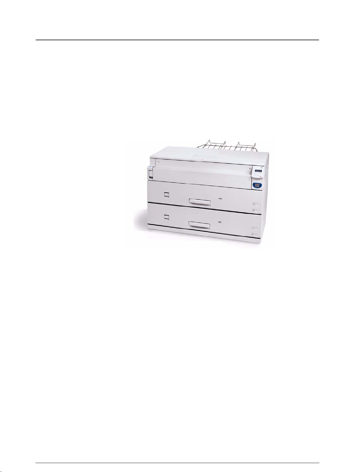
This unit is a printer only. Refer to the printer sections of this guide for
information about its setup, features, and usage.
Xerox 6030/6050 Wide Format Printer
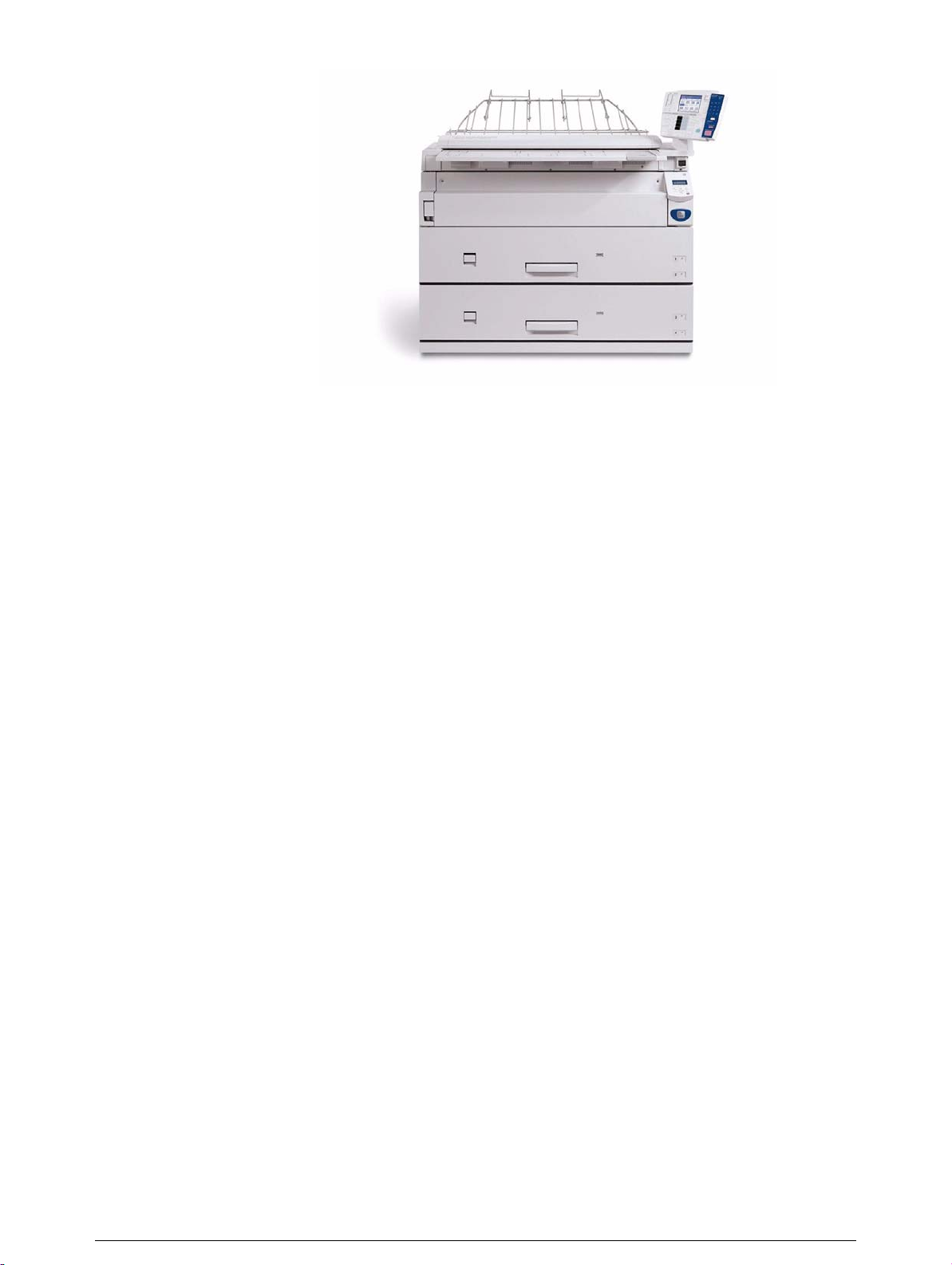
Xerox 6030/6050 Wide Format Copier/Printer
This unit features copier functionality through an integrated scanner and copier
control panel, plus the ability to receive and print jobs submitted to it from remote
workstations.
Xerox 6030/6050 Wide Format Copier/Printer
Page 29
Page 30
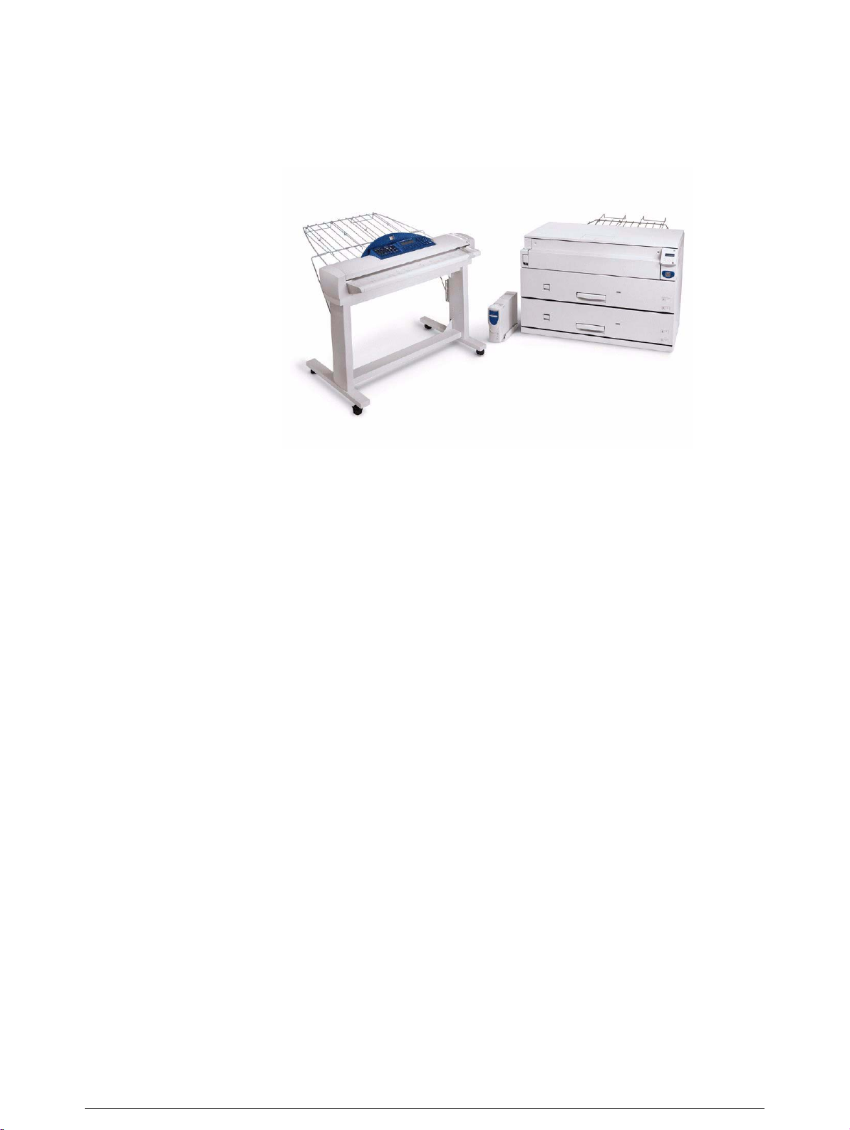
Xerox 6030/6050 Wide Format Printer with Scan System
This unit features copier and printer functionality, plus the Synergix® Scanner
and the AccXES
Xerox 6030/6050 Wide Format Printer with Scan System
® Controller.
Xerox 6030/6050 Wide Format Options
You may acquire additional hardware and software options for all units.
Contact your Xerox Sales Representative to obtain additional information on
options.
Page 31

1.2
Major Components
Major Components: Front
1 Document table
2 Setup screen
(touch screen)
3 Control panel
4 Document insertion
guide
5 Printer control panel Used to change the media size and type, set up
6 MSI*/Manual Feed Unit
(*Multi Sheet Inserter)
(optional)
7 Feeder LED Illuminates red when the media tray is in use.
Name Function
Documents to be scanned are inserted here.
Used to set up copy jobs, map originals to the
installed media, display messages and procedures,
and provide troubleshooting help, e.g., for jam
clearance.
Contains a numeric keypad, Start/Stop buttons, and
selection buttons for copy setups.
Helps the user align the edge of a document when
feeding it into the scanner.
printing and communication parameters, etc.
Used for printing or copying on cut sheet media.
8 Media tray (6050 only) A dual-roll media tray that feeds roll paper.
9 Media tray (Standard) A dual-roll media tray that feeds roll paper.
10 Scanner power switch Switches the power to the scanner on and off.
Page 32

Name Function
1 Toner supply port
Major Components: Rear
The toner is refilled through this port.
Name Function
1 Document ejection port
2 Power outlet socket Not available
3 Print ejection port Fused copies and prints exit the machine from this
4 Remote switch A selector switch that enables the user to switch the
Documents exit the scanner from this location.
location.
power to both the scanner and the printer on and off
from the Main Power Switch.
Page 33

Name Function
5 Interface connector The connector to which the printer is connected.
6 Serial port connector Used by the service representative for maintenance.
7 Circuit Breaker Switch Provides circuit breaker protection for the Copier/
Printer or Printer.
8 Paper Heater Switch Switches the paper heaters on and off.
9 Main Power Switch Switches the printer power on and off (if the Circuit
Breaker Switch is already switched on).
Connections to the host computer and other necessary connections will be taken care
of by your service representative.
Page 34

1.3
Powering On
Power On/Off
The scanner and the printer are each equipped with a power switch. The Circuit
Breaker Switch must be in the ON position to switch the printer and scanner
power on and off. No power is consumed when the Circuit Breaker Switch is in
the OFF position, even though the power plug is connected to the power source.
1 Set the Remote Switch to [Connect].
When the Remote Switch is set to
[Connect], and the Scanner Power
Switch is set to ON, the Main Power
Switch controls power to both the Printer
and the Scanner.
Scanner Power
Switch
Main Power
Switch
2 Switch ON the Scanner Power Switch.
3 Switch ON the Circuit Breaker Switch.
4 Switch ON the Main Power Switch.
Circuit Breaker
Page 35

Powering Off
Main Power
Switch
Switch off the power following the steps below.
Never switch off the power while the machine is printing. Failure to observe this
precaution may result in paper jams in the high-temperature areas of the printer.
1 Switch OFF the Main Power Switch.
When the remote switch is set to
[Connect], and the Scanner Power
Switch is set to ON, the power to the
Printer and Scanner can be switched on
and off with the Main Power Switch.
2 Switch OFF the Scanner Power Switch.
Circuit Breaker
Switch off the Circuit Breaker Switch if
the machine will not be used for a long
period of time.
Scanner Power
Switch
3 Switch the Circuit Breaker Switch to the
OFF position.
Page 36

1.4
Power Save Mode
The Power Save Mode automatically lowers the power consumption of the
machine by reducing the fuser power. The machine will enter the power save
mode when no prints or copies have been made for a preset period of time.
• Low power mode 1
This mode reduces the temperature of the fuser, thereby reducing power
consumption. The parameters that can be set up are [ON], [OFF], and the
time that must elapse before the mode activates (1 to 120 minutes; the
default setting is
[5 minutes].)
• Low power mode 2
This mode reduces the temperature of the fuser more than Low power
mode 1.
The parameters that can be set up are [ON], [OFF], and the time that must
elapse before the mode activates (5 to 120 minutes; the default setting is
[15 minutes].)
• Sleep Mode
The sleep mode automatically switches off the power to the printer. The
parameters that can be set up are [ON], [OFF], and the time that must
elapse before the mode activates (15 to 120 minutes; the default setting is
[90 minutes].)
Power is restored to normal levels when a print job is received by the printer, and
when the <Power Saver> key on the printer control panel is pressed.
The Power Save Mode settings can be accessed and changed using either the
<Custom Presets/Meter Check> key on the copier control panel, or the setup
menu on the printer control panel.
Refer to "3.4 System Parameter Setup (Printer Control Panel)" for changing the
power save mode settings from the printer control panel.
Page 37

1.5
Printer Control Panel Overview
Both the Printer and the Copier/Printer versions of the 6030/6050 Wide Format
are equipped with a printer control panel. This section provides an overview of
this device.
Refer to section "2.2 Printer Control Panel Usage" and "Chapter 5 Additional
Operations from the Printer Menu" for detailed explanations of the use of the
printer control panel.
It is seldom necessary to use the printer control panel on the 6030/6050 Wide
Format Copier/Printer because the same settings usually can be made using
either the copier control panel or Print Services on Web, the built-in web
interface.
Page 38

[Processing] lamp (green)
Indicates the printing status.
ON Printing in process
Blinking Receiving print data
OFF Not printing
<Power Saver> button
Activates the energy-saving mode.
Also cancels the energy-saving mode.
ON Energy-saving mode
activated.
OFF Energy-saving mode
deactivated.
Printer display
Used for setting up the
various functions. Displays
various messages.
[Online] lamp (green)
Indicates the data
processing status.
ON Ready to print.
Blinking Moving to the
offline mode.
OFF The offline mode.
Printing is not
possible.
<Manual Feed Mode> button
Currently not supported.
[Error] lamp (red)
Indicates a printing error.
ON Indicates that an error,
such as paper jamming,
has occurred.
OFF Printer operating
normally.
<Pause> button
Temporarily suspends a job
during printing.
<Set> button
Sets the values specified on
the menu screen.
<Cancel Job> button
Cancels a job during printing.
<Menu> button
Alternates between the online
mode and offline mode.
< > < > < > < > buttons
Displays the items and specified
values on the menu screen.
Page 39

1.6
Print Services on Web Overview
Print Services on Web is web server software which is pre-installed in the 6030/
6050 Wide Format Printer and Copier/Printer. Print Services on Web provides a
user-friendly way to perform printer setup, communication (port) setup, job and
error log management, and other procedures via a web browser. Print Services
on Web also enables the user to perform operations which can not be performed
from the printer control panel, for example, displaying job lists and changing job
priority.
Refer to the topic " Starting and Exiting Print Services on Web" in "2.3 Print Services
on Web" to l earn how to log on to Print Services on Web.
Page 40

Operating Modes
User Mode
The user mode interface (user page) is shown in the image below. This page
displays immediately after a user logs on to Print Services on Web. The
selections on the tabs enable the user to do the following.
[Job and Log] tab
[Status tab] Check the status of the Printer or Copier/Printer.
[Print Setup] tab View the logical printer settings.
Check the status of a print job.
View and print a job log.
Start a print job.
Refer to section "1.7 Logical Printers Overview" to learn more about logical printers.
Page 41

Administrator Mode
To enter the administrator mode, log on to Print Services on Web, select
the [Administrator page] button, and then enter the administrator login
and password when prompted to do so. The administrator page displays
two additional tabs, [Properties] and [Tools], and expands the capabilities
of the [Job and Log], [Status], and [Print Setup] tabs.
The selections on the Administrator page tabs enable the administrator to
perform the tasks listed below.
[Job and Log] tab • Check the status of jobs in the print queue.
[Status tab] • Check the status of the Printer or Copier/Printer.
• View and print the job log and the error log.
• Cancel a print job.
• Change the priority of a print job.
• Stop and start print services (job reception and printing).
• Stop and start job reception from client computers.
• Stop and resume print jobs.
[Print Setup] tab • Set up new logical printers for each of the allowable data
formats (HP-GL, TIFF, CALS, VERSATEC, PS/PDF).
• Edit the settings of existing logical printers.
[Properties] tab • View and change the machine configuration.
• View and change communications configurations.
• Manage ftp users.
[Tools] tab • Print a test pattern to verify machine (printer) operation.
• Print a Diagnostic Report.
Page 42

1.7
Logical Printers Overview
A logical printer (virtual printer) is a group of saved print job settings for a
particular data format, i.e., HP-GL, Versatec, TIFF, CALS, and PS/PDF. These
saved settings, which are created using Print Services on Web, may include pen
attributes, media type, print quantity, and the other parameters that define the
print job that the logical printer will be required to perform. Logical printers are to
printing as Stored Jobs are to copying, that is, both reduce setup time and
increase efficiency by using previously saved job settings. A maximum of one
hundred logical printers can be set up within one 6030/6050 Wide Format
Printer or Copier/Printer for each supported data format.
Refer to "Chapter 4 Logical Printer Setup and Operation" to learn how to set up
logical printers.
How Logical Printers are Named
PLT00H
Number
Format
Logical printer names are assigned based on the following. This naming
structure can not be changed.
1st to 3rd digits [PLT] or [plt] character strings
4th to 5th digits (number) Two-digit number from 00 to 99
6th digit (data format) Any of the following.
H: HP-GL format
V: Versatec format
T: TIFF format
C: CALS format
A: PS/PDF format (optional)
Page 43

1.8
Procedure
Loading Roll Media
The message ‘Replace xxx media." will display when there is no media loaded
or when the roll in use runs out.
The media size displayed on the control panel will turn off when there is no
media in the machine.
Two rolls of media can be loaded in each of the media trays.
Refer to the instructions provided in " Setting Up Media" and set up the media
parameters after the roll media has been loaded.
Media can be reloaded in the lower media tray while printing is occurring from the
upper media tray. Be sure that the Feeder LED on the lower media tray is off (not
illuminated) before opening the lower media tray.
1 Open the media tray.
2 Remove the shaft containing the roll paper
that is to be replaced.
Page 44

3 While pulling on the lever located in the end
of the roll paper shaft, remove the paper
core in the direction of the arrow.
Pulling the lever releases the lock and
allows the roll to be removed from the
shaft.
There is an area at the front of the tray on which
the roll paper can be placed.
4 While pulling the lever located in the end of
the roll paper shaft, align the roll paper with
the paper size marks on the shaft and set
the roll in place.
5 Align the roll paper following the directions
displayed inside the media tray and load the
roll on the shaft guide.
Cut the lead edge of the media before
setting it in place if it is damaged. Refer
to "1.11 Cutting Roll Media" for details
on how to do this.
Page 45

6 Rotate the roll media until the lead edge is
gripped in the roller.
Rotate the knob until the leading edge of
the paper can be seen in the window.
7 Gently but firmly close the media tray.
The LED on the front of the tray will illuminate,
and the roll paper will feed automatically to its
starting position.
8 Set up the media parameters on the copier
control panel.
" Setting Up Media"
The media parameters also may be set up on the printer control
panel.
"Chapter 5 Additional Operations from the Printer Menu"
Page 46

1.9
Drawer Media Size Indicators
The media size indictors help the user identify the media that is loaded in each
of the drawers. These indicators are visible on the right hand side of the
drawers. Usage instructions begin on the next page.
The following types are available.
• Standard size A
• Inch size A
Standard size A
SB1Sp.A1A3A1
B2 Sp.A2 Sp.A0 A2 A0
Inch size A
12”18”24”34”
11” 17” 22” 30” 36”
Page 47

Inserting media size sheets
1 Open the tray.
2 Remove the media size sheet.
3 Fold the sheet so that the size loaded is
displayed.
4 Insert the media size sheet.
Page 48

5 Gently but firmly close the media tray.
Page 49

1.10
Loading Media for Manual Feeding
1 Adjust the (MSI) Multi Sheet Inserter/
Manual Feed Unit's side guides to fit the
size of the media that is to be printed.
2 Place the side of the media to be printed
face up, and align it with the (MSI) Multi
Sheet Inserter/Manual Feed Unit's side
guides.
• The optional (MSI) Multi Sheet
Inserter/Manual Feed Unit is
required when making manually fed
copies.
• Standard paper having a width of
297 to 914 mm and a length of 210
to 2,000 mm can be used with the
(MSI) Multi Sheet Inserter/Manual
Feed Unit.
3 Push the front edge of the media as far into
the machine as it will go. You will hear the
sound of a motor as the machine lifts the
media to the feed position.
Two or more sheets of A3 (horizontal
feed) and A4 (horizontal/vertical feed)
size paper can be placed in the MSI.
Paper sizes other than A3 (horizontal
feed) and A4 (horizontal/vertical feed)
sizes must be in se rted o n e sh ee t a t a
time.
Only Bond paper can be used in the
(MSI) Multi Sheet Inserter/Manual
Feed Unit.
4 Make the required media settings on the copier control panel.
Page 50

1.11
Cutting Roll Media
The lead edge of the media should be cut when the media is loaded, on
recovery from a media jam, and when the lead edge of the roll is damaged.
There are two methods for cutting the lead edge of the roll media:
• Automatic cut: This involves making selections on the printer control panel.
Refer to the section "5.8 Automatic Cut Using the Printer Con trol Panel" in
"Chapter 5 Additional Operations from the Printer Menu" for details about
automatic cutting.
• Manual cut: Open the media tray and slide the cutter manually.
Refer to section " Cutting Roll Media Manually" in this chapter.
Page 51

Cutting Roll Media Manually
Cutting the Front Roll
1 Open the media tray.
2 Pull the lever to open the tray cover.
Lever
3 Rotate the roll media until the lead edge is
gripped by the roller.
Page 52

4 Rotate the knob until the media's lead edge
protrudes from the tray outlet.
5 Grasp the cutter by the handle and slide it
to the opposite side of the tray to cut the
paper.
CAUTION: Use the cutter handle to
prevent personal injury which may
result from sliding your fingers along the
sharp, metal cutting bar.
Window
6 Remove the cut off media.
7 Close the tray cover.
8 Return the media to its original location by
rotating the knob until the lead edge can be
seen in the window.
Page 53

9 Close the media tray.
Page 54

Cutting the Rear Roll
1 Open the media tray.
2 Rotate the roll paper until the lead edge is
gripped by the roller.
3 Rotate the knob until the media's lead edge
protrudes from the tray outlet.
4 Pull the lever to open the tray cover.
5 Rotate the knob until the paper passes
through the tray outlet.
Page 55

6 Grasping the cutter by the handle, slide the
cutter to the opposite side of the tray to cut
the paper.
CAUTION: Use the cutter handle to
prevent personal injury which may
result from sliding your fingers along the
sharp, metal cutting bar.
7 Remove the media that was cut off.
8 Close the tray cover.
9 Return the media to its original location by
rotating the knob until the lead edge can be
seen in the window.
10 Close the media tray.
Page 56

Page 57

Chapter
Chapter 0
2
Printer Overview
Chapter 2
Page 58

2.1
Overview of the 6030/6050 Wide Format Print Service
This section provides an overview of the 6030/6050 Wide Format print service.
What is the 6030/6050 Wide Format Print Service?
The 6030/6050 Wide Format print service is software that processes print jobs
that it receives from a client. The 6030/6050 Wide Format print service enables
all types of image data to be printed in the supported formats, including standard
and non-standard size documents, enlarged and reduced images, and split
(fragmented) images. It also allows the user to view the status of print jobs,
cancel print jobs, and change print job priority.
Data Formats that can be Processed
Processing is possible for the following data formats.
• HP-GL formats (HP-GL, HP-GL/2, HP-RTL)
• VERSATEC formats (VRF, VCGL)
• TIFF formats (conforming to TIFF Revision 6.0)
• CALS formats (CALS Type 1)
• PS/PDF formats (PostScript 3.0, PDF Version 1.3)(Optional)
Communication Interfaces
The following communication interfaces are supported.
• Ethernet (100Base-TX and 10Base-T)
• RS232C
• Centronics (optional)
• VPI (optional)
Page 59

Printing Methods
Documents may be submitted from a client to the 6030/6050 Wide Format
Printer using any of the following.
• Ethernet (Direct) Printing
This capability is for UNIX systems. Printing takes place over TCP/IP networks
using the ftp and lpr commands.
• Wide Format Windows Driver
The Microsoft®Windows® print drivers (32 bit only) enable users to print
documents from various Windows applications.
Refer to "Chapter 11 Ethernet Print Service (for UNIX)" for details on available
functions.
Serial output is not supported by the Wide Format Windows Driver.
Refer to the Xerox 6030/6050/6204 Wide Format Windows Driver User Guide for
details on available functions.
• BT-PlotAssistant (Ver. 3.4.0 or later)(Optional)
BT-PlotAssistant is printer support software that runs on Windows operating
systems. Using BT-PlotAssistant’s simple user interface, the user can submit
documents to the 6030/6050 Wide Format printer.
Refer to the Xerox 6030/6050/6204 Wide Format BT Plot Assistant User Guide for
details on available functions.
• PostScript/PDF Driver (PS/PDF)(Optional)
The PostScript/PDF driver provides enhanced printing performance and enables
users to print PDF documents. The customer who purchases the PS/PDF driver
is provided with a Feature Key which is required for driver installation.
Refer to the Xerox 6030/6050/6204 Wide Format PostScript Driver User Guide for
details on available functions.
Page 60

Print Service Operations
The printer control panel and Print Services on Web are the two main features
that enable users to set up and perform print service operations.
Printer Control Panel
The printer control panel can be used to perform a variety of tasks, among them:
• media setup for roll media and the MSI (Multi Sheet Inserter/Manual Feed
Tray)
• communication (port) setup
• system parameter setup
• printing of test patterns to verify printer operation
• job log and error log management
• reprinting of the most recent print job
• displaying billing meter information
Refer to "2.2 Printer Control Panel Usage" for more details on the printer control
panel and its usage.
Page 61

Print Services on Web
Print Services on Web is web server software which is pre-installed in the 6030/
6050 Wide Format. Print Services on Web provides a user-friendly way to
perform printer setup, communication (port) setup, log management, and other
procedures via a web browser.
Print Services on Web also enables the user to perform operations which can
not be performed from the printer control panel, for example, displaying job lists,
changing job priority, and starting and stopping the server.
Refer to "2.3 Print Services on Web" for further details on Print Services on Web and
its operation.
Page 62

Main Printing Functions
This section describes the main printing functions which are available with the
6030/6050 Wide Format Printer and Copier/Printer.
Logical Printers
A logical (virtual) printer is a group of saved print job settings for a particular data
format, i.e., HP-GL, Versatec, TIFF, CALS, and PS/PDF. These saved settings,
which are created using Print Services on Web, may include pen attributes,
media type, print quantity, and the other parameters that define the print job that
the logical printer will be required to perform. Logical printers are to printing as
Stored Jobs are to copying, that is, both reduce setup time and increase
efficiency by using previously saved settings. A maximum of one hundred logical
printers can be set up within one 6030/6050 Wide Format Printer or Copier/
Printer for each supported data format.
Logical printer names are assigned based on the following. It is not possible to
change these names.
PLT00H
Number
Format
1st to 3rd digits [PLT] or [plt] character strings
4th to 5th digits (number) Two-digit number from 00 to 99
6th digit (format) Any of the following.
H: HP-GL format
V: Versatec format
T: TIFF format
C: CALS format
A: PS/PDF format (optional)
The sixth digit can be omitted when Ethernet multi-data format functions are in
use. When this digit is omitted, the relevant software to be started will be
selected according to the extension log of the transmitted data file.
If a logical printer is selected that has a different sixth digit than the format of the
print file, the file may be forwarded to a logical printer that has the same
extension as the transmitted file.
Page 63

Document Size Input
The following two methods are available for judging the size of the input
document:
• Automatic Calculates the coordinates of the input document and
• Size SpecificationEnables the user to manually select the media size of the
The Automatic setting is used under normal circumstances. Specify the size
manually if restrictions are to be placed on the input coordinates. When the size
is specified, all areas that exceed that size will be cut off.
• Refer to "3.5 System Parameter Setup (Print Services on Web)" for details on
setting up the logical printer extensio ns .
• Refer to "4.1 Creating a New Logical Printer" for help in setting up logical printers.
automatically selects the closest size.
input image. The media size can be selected from standard
sizes and user-defined sizes.
Refer to the "Input Option" section of "4.3 Logical Printer Prin t Settings" for details
on available functions.
Media Size Output
The following two methods for judging the size of the output media are available:
• Automatic When Automatic is selected, the print size is enlarged or
• Size SpecificationWhen Size Specification is selected, the output media size is
"Automatic" is used under normal circumstances. Specify the media size
manually if all output is to be printed on a single media size.
reduced automatically based on a size mapping table
(explained later). Also, the size of the media that is selected
is determined based on a media mapping table, or by
automatic mapping (explained later).
specified manually. If the specified media size is different
from the input document size, the document will be enlarged
or reduced to match the size of the paper.
Refer to "4.3 Logical Printer Print Setting s" fo r details on available functions.
Page 64

Size Mapping
Size mapping is the process of setting up a table that establishes relationships
between input document sizes and output image sizes. When size mapping is
finished (must be done prior to printing), documents can be enlarged or reduced
automatically based on the table entries.
A1
Enlarge
A2
Input document size
Reduce
Refer to " Size/Media Mapping" in "4.3 Logical Printer Print Settings" for more
details.
Media Mapping/Automatic Mapping
Media mapping is the process of setting up a table that establishes relationships
between output image sizes and media sizes. This process, like size mapping,
must be performed prior to printing. Once the media mapping table is finished,
the media size is determined by the entries in the media mapping table.
When Automatic Mapping is selected, the output media size that matches the
output image size will be selected.
Check media mapping to be sure the media size selected matches the media loaded in the
printer. Refer to "4.3 Logical Printer Print Settings" for more details.
A3
Output image size
A3 A3
Output document size
Rotated 90 degrees
Paper
A3
Output on A3 roll media
Output on A2 roll media
Page 65

Plot Area, Auto-Layout, and Offset
It is possible to print a specified area of an input document. The specified area
can be printed in the center of the media or moved to another position (autolayout, offset).
Refer to the "Plot Area" section of "4.3 Logical Printer Print Settings" for details on
available functions.
Plot area
Input document
Mirror Image, 90-Degree Rotation
These functions perform mirroring (Mirror Image) or 90-degree rotation
processing on the output image.
Refer to the "Transform" section of "4.3 Logical Printer Print Settings" for details on
available functions.
Auto-layout
Offset
Output images
Input document
Mirror image
90-degree rotation
Output images
Page 66

Split Drawing (Image Fragmentation)
Long images (those that exceed 1,189 mm in length) may be split into several
parts and printed. Positioning marks can be added to the split prints for
positioning purposes.
Refer to "Split Drawing" in "4.3 Logical Printer Print Settings" for more details.
Fragment
Printing the Output Time
Fragment
1/3
2/3
3/3
The date and time a document is printed can be added to the edge of the
document.
Log Management
It is possible to print out a log of completed print jobs, an error log, and other
information.
Reprinting
The most recently printed document can be reprinted. The print quantity also
can be specified.
Refer to the "Message Option" section of "4.3 Logical Printer Print Settings" for
details on available functions.
Refer to "10.4 Managing th e Job a nd Error Logs" for det ail s on pr in te r co ntrol panel
operations.
Reprinting is not possible with the Xerox 6030 WF or Xerox 6050 WF if a copy job is
performed after the print operation.
Refer to "10.5 Reprinting" for details o n a v ailable functions.
Page 67

Canceling Jobs
Jobs transmitted to the 6030/6050 Wide Format can be deleted by pressing the
<Cancel Job> key on the printer control panel. It is also possible to cancel jobs
from Print Services on Web.
Meter Display
The billing meters can be checked from both Print Services on Web and the
printer control panel.
Job Recovery
This machine is equipped with a recovery function for media jams and when
media runs out.
Refer to "2.2 Printer Control Panel Usage" for details on the <Cancel Job> key, and
"4.5 Print Services on Web: Job and Log" for details on Print Service on Web
operations.
Refer to "4.6 Print Services on Web: Status " for det ail s on web operat ion s, and "10.6
Billing Meter Confirmation" for deta ils on printer control panel operations.
• Media Jams
Documents that failed to print because of a media jam will print when the jam is
cleared.
• No Media
Printing of a print job that is stored in memory will restart when the media is
loaded in the printer.
The printer also can be set up to print (or not print) jobs that remained in the print
queue when the printer was switched off.
Refer to "8.4 System Parameter Setup (Printer Control Panel)" and to the topic
"Setting Up [Job Recovery]" in "3.5 System Parameter Setup (Print Services on
Web)" for details on job processing after the power is switched on.
Page 68

2.2
Printer Control Panel Usage
This section describes the names and functions of the printer control panel
components.
[Processing] lamp (green)
Indicates the printing status.
ON Printing in process
Blinking Receiving print data
OFF Not printing
Printer display
Used for setting up the
various functions. Displays
various messages.
[Online] lamp (green)
Indicates the data
processing status.
ON Ready to print.
Blinking Moving to the
offline mode.
OFF The offline mode.
Printing is not
possible.
<Power Saver> button
Activates the energy-saving mode.
Also cancels the energy-saving mode.
ON Energy-saving mode
activated.
OFF Energy-saving mode
deactivated.
[Error] lamp (red)
Indicates a printing error.
ON Indicates that an error,
such as paper jamming,
has occurred.
OFF Printer operating
normally.
<Pause> button
Temporarily suspends a job
during printing.
<Set> button
Sets the values specified on
the menu screen.
<Manual Feed Mode> button
Currently not supported.
<Menu> button
Alternates between the online
mode and offline mode.
Press the < > and < > keys simultaneously to reset the printer when an error code
is displayed.
<Cancel Job> button
Cancels a job during printing.
< > < > < > < > buttons
Displays the items and specified
values on the menu screen.
Page 69

Basic Printer Control Panel Operations
The printer must be in the offline mode before settings can be changed.
Pressing the <Menu> key switches the printer to the offline mode and displays
the menu screen.
Button Functions
The following buttons are used to navigate the menu screen.
<Menu> key Switches the printer to the offline mode and displays the menu
screen. The printer returns to the online mode when this
button is pressed again.
<> key Displays the previous menu item or value on the same menu
level.
<> key Displays the next menu item or value on the same menu level.
<> key Displays the lower level menu item.
< > key Displays the higher level menu item.
<Set> key Accepts the value selected by the user.
An asterisk [*] displays on the right side of the value once it is
selected by pressing the <Set> key.
Page 70

Overview of the Operation Menu
The printer control panel’s operation menu is depicted in the image below.
Descriptions of the sub-menus follow.
Online Mode
Ready to print
<Menu> button
< > button
MENU
NETWORK/PORT SET
MENU
PRINT SETUP
< > button
Offline Mode
Return to higher level
Move to lower level
MENU
SYSTEM PARAMETER
MENU
PORT SETTING
MENU
TEST PLOT
MENU
JOB LOGGING
MENU
OFFLINE PLOT
< > button
< > button
SYSTEM PARAMETER
Set Date
SYSTEM PARAMETER
AUTO ROLL
SYSTEM PARAMETER
SPA PAPER WIDTH
Specified values:
Select with the < >
and < > buttons,
and set with the <Set>
button.
SPA PAPER WIDTH
Sp A1
SPA PAPER WIDTH
Sp A2
Return to the previous
Return to higher level
SYSTEM PARAMETER MENU
Sets up the system management information, such as the system date and
power save mode settings.
Refer to "8.4 System Parameter Setup (Printer Control Panel)" for setup procedures.
MENU
BILLING INFO
Operation menu
Page 71

PORT SETTING MENU
Sets up the communication parameters that are required for connecting to the
host.
Refer to "8.2 Communication Parameter Setup (Printer Co ntrol Panel)" for set up
procedures.
TEST PLOT MENU
Prints test patterns to help verify printer operation.
Refer to "10.3 Test Printing" for logical printer details and operations.
JOB LOGGING MENU
Prints job and error logs.
Refer to "10.4 Managing the Job and Error Logs" for logical printer details and
operations.
OFFLINE PLOT MENU
Reprints the most recently printed job.
BILLING INFO MENU
Displays the amount of roll media that has been used for both copy and print
jobs in linear and square feet and meters.
Refer to "10.5 Reprinting" for logical printer details and operations.
Refer to "10.6 Billing Meter Confirmation" for logical printer details and operations.
Page 72

Operation Examples
This section provides examples of how to select menu items.
<Menu> key
Ready to print
MENU
NETWORK/PORT SET
1 Press the <Menu> key.
The machine will enter the offline mode.
<> key
MENU
SYSTEM PARAMETER
<> key
MENU
PORT SETTING
<> key
PORT SETTING
TCP/IP
<><> key
PORT SETTING
SERIAL
2 Press the < > key.
The top selection in the [NETWORK/PORT
SET] menu will display.
3 Press the < > key.
The menu items will display in order.
The previous menu will display if the < >
key is pressed.
4 Press the < > key.
The sub-menu items will display.
5 Press the < > key.
The menu items on the same level will
display in order.
<> key
SERIAL
Handshake
<> key
PORT SETTING
SERIAL
<> key
MENU
PORT SETTING
6 Press the < > key.
The menu items on the next level will
display.
7 Press the < > key to return to the higher
level.
8 Press the < > key to return to an even
higher level.
Page 73

Setting Up a Value
This section provides an example of setting up a value.
SYSTEM PARAMETER
Smoothing
<> key
Smoothing
ON
<><> key
Smoothing
OFF
<Set> key
Smoothing
OFF
1 Select the menu item that you want to set
up so that it displays on the screen.
2 Press the < > key.
The current value will display.
*
An asterisk [*] is displayed beside the
current value.
3 Use the < > and < > keys to change the
setting.
The asterisk [*] will be removed when the
setting is changed.
4 Press the <Set> key to specify and confirm
the new value.
*
The asterisk [*] will display beside the new
value.
<> key
SYSTEM PARAMETER
Smoothing
5 Press the < > key to return to the next
higher menu level.
Page 74

Entering Numbers and Characters
This section provides examples of how to enter numbers and characters.
SYSTEM PARAMETER
Low power mode1
<> key
Timer Value
05
<><> key
Timer Value
15
<> key
Timer Value
15
1 Select the menu item that you want to set
up.
2 Press the < > key.
The current setting for the selected item will
*
display.
3 Set up the first number using the < > and
< > keys. The value will increase or
decrease sequentially between 0 and 9.
In the example on the left, press the < >
key to display [2].
4 Press the < > key.
The cursor will move to the second number.
Press the < > key to return to the
previous number.
<><> key
Timer Value
16
<Set> key
Timer Value
16
<> key
Timer Value
16
<> key
MENU
SYSTEM PARAMETER
5 Set up the second number using the < >
and < > keys.
6 Set up all other numbers in the same way.
Press the <Set> key after all numbers are
*
set up.
The [*] mark will display beside the new
value.
7 Press the < > key to move the cursor to
the first number.
*
8 Press the < > key to return to the higher
level menu.
Page 75

2.3
Print Services on Web
Print Services on Web is web server software which is pre-installed in the 6030/
6050 Wide Format. Print Services on Web enables the user to perform the
following procedures from a workstation using a web browser.
• Set up communication parameters
• Set up logical printers (print setup)
• Display the machine status
• Manage print jobs
• Manage job and error logs
• Set up system parameters
• Print test patterns
Operating Environment
Print Services on Web operates in the following environment.
Operating Systems Microsoft
Microsoft
Microsoft
Browsers Microsoft
Enable the java script setting when using Print Services on Web. Also, set the
browser at [Don't use proxy server].
®
Windows®2000
®
Windows®XP
®
Windows® Server 2003
®
Internet Explorer 6.x or later
Page 76

Starting and Exiting Print Services on Web
This section explains how to start and exit Print Services on Web.
Start Print Services on Web
1 Start the browser.
2 Enter the URL for the 6030/6050 Wide Format (http://Home name or IP
address) in the browser's address field, and then press the <Enter>
key.
Exit Print Services on Web
1 To exit Print Services on Web, either click the [¥] button located at the
top right corner of the browser, or select [File] > [Exit].
Page 77

Print Services on Web Organization
This section explains the various pages contained within Print Services on Web.
User Page
This is the first page displayed when connecting with the Print Services on Web.
The user page allows users to do the following.
[Job and Log] tab
[Status tab] Check the status of the Printer or Copier/Printer.
[Print Setup] tab View the logical printer settings.
Administrator Page
The administrator page (see next page) displays after the user selects the
[Administrator page] button on the user page, and then enters the user name
and password in the logon dialog box.
Check the status of a print job.
View and print a job log.
Start a print job.
Page 78

The administrator page permits the following.
[Job and Log] tab
• Check the status of jobs in the print queue.
• View and print the job log and the error log.
• Cancel a print job.
• Change the priority of a print job.
[Status tab] • Check the status of the Printer or Copier/Printer.
• Stop and start print services (job reception and printing).
• Stop and start job reception from client computers.
• Stop and resume print jobs.
[Print Setup] tab • Set up new logical printers for each of the supported data
formats (HP-GL, TIFF, CALS, VERSATEC, PS/PDF).
• Edit the settings of existing logical printers.
[Properties] tab • View and change the machine configuration.
• View and change communications configurations.
• Manage ftp users.
[Tools] tab • Print a test pattern to verify machine (printer) operation.
• Print a Diagnostic Report.
Page 79

Online Help
Click the Help [?] button displayed at the top, right corner of the window to
display the online help. The online help enables you to answer many questions
related to using Print Services on Web.
Page 80

Page 81

Chapter
Chapter 0
3
Printer Setup
Chapter 3
Page 82

3.1 Communication Parameters
The 6030/6050 Wide Format Printer and Copier/Printer must be connected to a host PC
before printing can be performed. Once the Printer or Copier/Printer is connected to the
network, the communication parameters must be set up. The communication parameters
can be set up from either the printer control panel or from Print Services on Web. This
section explains how to use both methods to perform the setup procedures. Explained,
too, is the procedure for printing a list of the communication parameters.
Communication Parameters Definitions
Communication parameters may be defined for the following.
• TCP/IP
• Serial
• Centronics (optional)
• VPI (optional)
• SNMP
SNMP can only be set up from Print Services on Web.
Page 83

TCP/IP
The communication parameter nomenclature on the printer control panel will
sometimes differ from the nomenclature on Print Services on Web. The Print
Service on Web nomenclature appears in bold type in the table below.
The following TCP/IP communication parameters must be set up.
Menu Item Description
Default Parser
Selects the parser or data format interpreter that will be
used when the input data format has not been specified
from among the available selections, that is, [
VERSATEC], [TIFF], [CALS], or [PS/PDF]. The
[
default setting is [HPGL].
Ethernet Setting
(Physical Layer)
Selects the ethernet setting/physical layer. The default
setting is [
AUTO] Automatic recognition
[
10BASE_T] Fixed at 10BASE_T
[
100BASE_T] Fixed at 100BASE_T
[
AUTO].
IP Address The IP address of the machine in the format
XXX.XXX.XXX.XXX. The IP address can be
changed, if necessary.
MASK Value
(Net mask)
The sub-net mask set up on the machine in the format
XXX.XXX.XXX.XXX. The subnet mask can be
changed, if necessary.
E-Net Address
(Ethernet address)
Displays the Ethernet address. The value displayed is
unique for the hardware and cannot be changed.
HPGL],
FTP Determines whether or not to enable FTP. The default
setting is [Enable].
Dynamic Routing Determines if dynamic routing will be enabled. The
default setting is [ON].
Static Routing* Determines if static routing will be enabled. The
default setting is [OFF]. Set Static Routing to [ON]
when you need to view the device through a gateway
or router.
Page 84

*The routing table can be edited if [Static Routing] is set to [Enable].
A maximum of 512 items can be saved in the routing table. The [Registration Not
Possible] screen will display if the number of items exceeds 512.
Menu Item Description
ROUTING TABLE
Dest. Address
Select [ADD] to enter additional routing information.
Sets the network address for the destination.
Enter in the XXX.XXX.XXX.XXX format. Typically not
needed.
Router Address Sets the router address for the local machine or subnet.
Enter in the XXX.XXX.XXX.XXX format.
Page 85

Serial
The serial communication parameters are listed below.
The communication parameter nomenclature on the printer control panel will
sometimes differ from the nomenclature on Print Services on Web. The Print
Service on Web nomenclature appears in bold type in the table below.
Menu Item Description
Default Parser
Logical printer
number
The default setting is [HP-GL].
Sets up a logical printer number to be use if a logical printer is
not defined in the print job.
Handshake Selects the handshake method from the following choices.
The default setting is [XON/XOFF].
XON/XOFF] Handshake using the XON/XOFF protocol.
[
HARDWARE] Handshake using the hardware.
[
ENQ-ACK] Handshake using the ENQ-ACK protocol
[
(HP-GL only).
SOFTWARE] Handshake using the application program
[
(HP-GL only).
Baud Rate Sets the communication speed to [300], [1200], [2400],
4800], [9600], or [19200].
[
The default setting is [9600].
Parity Sets the parity bit to [NONE], [EVEN], or [ODD].
The default setting is [EVEN].
Data Bit Sets the data bit length to [7_BITS] or [8_BITS].
The default setting is [7_BIT].
Stop Bit Sets the stop bit length to [1_BIT] or [2_BIT].
The default setting is [1_BIT].
EOP Timeout Determines whether or not to enable EOP timeout.
The default setting is [ON] or [Enable].
Timeout Value Sets up the EOP timeout value within a range of 1 to 255
seconds. If a value greater than 255 is entered, the timeout value
will be set to 255.
The default setting is [10].
Output
Response
Enables [YES] or disables [NO] the output response.
This must be set to [
YES] if the printer requires a response when
data is transmitted from the host to the printer.
The default setting is [
NO].
Page 86

Menu Item Description
Job Separation
(Page limit)
Sets up the job separation option. The default setting is [NO].
YES] Starts data conversion once the command that
[
recognizes the end of the data is received, even
if it occurs midway through the file.
NO] Spools data on the hard disk until the timeout is
[
issued.
Page 87

Centronics (optional)
The Centronics communication parameters are presented below.
Menu Item Description
Ack Mode
The Ack mode is selected from [MODE0], [MODE1],
MODE2], [MODE3], and [MODE7].
[
The default setting is [MODE0].
DMA Timeout The timeout value for data input is entered within a range of 1 to
255 seconds. The default setting is [5 sec].
EOP Timeout Determines if the EOP Timeout will be enabled [TIMEOUT] or
disabled [NO_TIMEOUT]. If set to [TIMEOUT], a Timeout
Value must be entered. The timeout value is entered within a
range of 0 to 99 seconds.
The default setting is [10 sec].
Job Separation Sets the job separation. The default setting is [NO].
YES] Starts conversion processing once the command
[
that recognizes the end of the data is received,
even if this occurs midway through the file.
NO] Performs the spooling process on the hard disk
[
until a timeout is issued.
• If a value higher than [255] is entered for the DMA Timeout value, [255] will be set
as the value.
• Changes to the [Ack Mode] and [DMA Timeout] values will have no effect on
operations.
Page 88

VPI (optional)
The following VPI communication parameters must be set up.
Menu Item Description
REPORT
OFFLINE
EOP Timeout Determines if the EOP Timeout will be enabled [TIMEOUT] or
Job Separation Sets the job separation. The default setting is [NO].
*If a value higher than [255] is entered for the timeout value, [255] will be set as the
value.
Determines if the host will be notified offline of the media
running out.
The default setting is [NO].
YES] Issues offline notification.
[
NO] Does not issue offline notification.
[
disabled [NO_TIMEOUT]. If set to [TIMEOUT], a Timeout
Value must be entered. The timeout value is entered within a
range of 1 to 255* seconds.
The default setting is [10 sec].
YES] Starts conversion processing once the command that
[
recognizes the end of the data is received, even if
this occurs midway through the file.
NO] Performs the spooling process on the hard disk until
[
a timeout is issued.
Page 89

SNMP
The communication parameters listed below must be set up.
SNMP must be set up in Print Services on Web.
The communication parameter nomenclature on the printer control panel will
sometimes differ from the nomenclature on Print Services on Web. The Print
Service on Web nomenclature appears in bold type in the table below.
Menu Item Description
SNMP
Community
String
Sets whether or not to enable SNMP.
Sets the community String to be imbedded when the client
transmits SNMP packets.
Trap address Sets the IP address of the destinations (trap transmission
destinations) to which notifications are to be sent in the event
of an error occurring with the printer.
A maximum of 128 trap transmission destinations can be
saved.
Transmission Port
Sets the port numbers of the trap transmission destinations.
(Send port)
Version Sets the version of the trap to be transmitted.
Permanence
(Persistence)
Sets whether the trap transmission destination information is to
be stored or not after the printer has been switched off. A
maximum of eight items can be enabled for permanence.
Page 90

3.2
Procedure
Communication Parameter Setup (Printer Control Panel)
This section explains the procedures for setting up the communication parameters from
the printer control panel.
SNMP must be set up from Print Services on Web.
The changed parameters become valid after the machine is rebooted.
MENU
PORT SETTING
PORT SETTING
TCP/IP
TCP/IP
Ethernet Setting
Ethernet Setting
AUTO
1 Press the < > key with [PORT SETTING]
displayed.
2 Select the interface that is to be set up with the
use of the < > and < > keys, and then press
the < > key.
[TCP/IP], [SERIAL], [CENTRO], and [VPI]
will be displayed, in that order.
[CENTRO] and [VPI] are optional.
3 Select the parameters with the use of the < >
and < > keys, and then press the <Set> key.
An asterisk [*] will be displayed on the right
side of the value once it has been set up.
*
The changed parameters are saved to the
system when the <Set> key is pressed. It
is not necessary to save each change
individually.
Refer to the previous section for detailed
information about each of the
communication parameters.
4 After setting up all of the parameters, switch the
printer power off and then on for the changes to
take effect.
Page 91

TCP/IP Setup
PORT SETTING
TCP/IP
TCP/IP
Default Parser
Default Parser
HPGL
1 Display [TCP/IP] on the selection screen, and
then press the < > key.
2 Select the item that is to be set up with the use of
the < > and < > keys, and then press the
<> key.
[Ethernet Setting], [Default Parser], [IP
Address], [Mask Value], [E-Net Address],
[Dynamic Routing], and [Static Routing] will be
displayed in that order.
• Additions can be made to the routing
table when [Static Routing] is enabled.
• The [E-Net Address] can only be
displayed, not changed.
3 Select the parameters with the use of the < >
*
and < > keys, and then press the <Set> key.
An asterisk [*] will be displayed on the right
side of the parameters once they have been set.
IP Address
100. 000. 000. 000
IP Address
120. 000. 000. 000
IP Address
123. 123. 123. 001
Entering addresses
1. Move the cursor to the left and right with the
use of the < > and < > keys.
2. Select the required value with the use of the
< > and < > keys. The value will increase
or decrease sequentially between 0 and 9.
3. Press the <Set> key once all values have been
*
entered.
• To proceed to the next menu, move the
cursor to the right-han d side and pr ess
the < > key.
• To return to the previous menu, move
the cursor to the left-hand side and
press the < > key.
Page 92

Static Routing
ON
Adding items to the routing table
*
1. Select [ON] for [Static Routing], and then
press the <Set> key.
Now press the < > key.
ROUTING TABLE
ADD
Dest. Address
123. 000. 000. 000
Router Address
123. 000. 000. 000
2. Select [ADD] for the [ROUTING TABLE],
and then press the < > key.
3. Enter the destination address, and then press
the <Set> key.
After setting up the destination address, move
the cursor to the right-hand side and press the
<> key.
4. Enter the routing address, and then press the
<Set> key.
To return to the pr evious menu, move the
cursor to the left-h and s ide and press the
<> key.
Page 93

Serial Setup
PORT SETTING
SERIAL
SERIAL
Baud Rate
Baud Rate
300
1 Display [SERIAL] on the setup item selection
screen, and then press the < > key.
2 Select the item that is to be set up with the use of
the < > and < > keys, and then press the
<> key.
[Handshake], [Baud Rate], [Parity], [Data Bit],
[Stop Bit], [EOP Timeout], [Output Response],
and [Job Separation] will be displayed in that
order.
3 Select the parameters with the use of the < >
*
and < > keys, and then press the <Set> key.
An asterisk [*] will display on the right side of
the parameters once they have been set.
Page 94

Centronics (optional) Setup
PORT SETTING
CENTRO
CENTRO
DMA Timeout
DMA Timeout
005 sec
1 Display [CENTRO] on the setup item selection
screen, and then press the < > key.
2 Select the item that is to be set up with the use of
the < > and < > keys, and then press the
<> key.
[Ack Mode], [DMA Timeout], [EOP Timeout],
and [Job Separation] will display, in that order.
3 Select the parameters with the use of the < >
*
and < > keys, and then press the <Set> key.
An asterisk [*] will display on the right side of
the parameters once they have been set.
Page 95

VPI (optional) Setup
PORT SETTING
VPI
VPI
Job Separation
Job Separation
YES
1 Display [VPI] on the setup item selection
screen, and then press the < > key.
2 Select the item that is to be set up with the use of
the < > and < > keys, and then press the
<> key.
[REPORT OFFLINE], [EOP Timeout], and [Job
Separation] will display, in that order.
3 Select the parameters with the use of the < >
*
and < > keys, and then press the <Set> key.
An asterisk [*] will display on the right side of
the parameters once they have been set.
Page 96

3.3
Procedure
Communication Parameter Setup (Print Services on Web)
The communication parameters for TCP/IP, Serial, Centronics (optional), VPI
(optional), and SNMP can be set up from Print Services on Web. These procedures are
explained below.
• The machine must be rebooted for the changes to take effect.
• These procedures are performed in the Administrator Mode.
1 Start Print Services on Web, enter the Administrator mode, and select the
[Properties] tab.
Refer to "2.3 Print Services on Web" for details about starting Print Services
on Web and logging on as Administrator.
The displayed [Print settings] were set up earlier using the selections on the
[Print Setup] and the [Properties] tabs. The hardware configuration
information is stored in the machine’s controller.
Page 97

2 Select the interface or protocol ([TCP/IP], [Serial], [Centro], [VPI], [SNMP])
to be set up from the [System parameters] menu.
The setup selections will display in the right-hand pane of the window. In the
example below, [Serial] has been selected.
• Only standard features and installed options are listed in the [System
parameters] menu. [VPI] and/or [Centro] will be listed if one or both of
these options is installed.
• Refer to the section " Communication Parameters Definitions" in "3.1
Communication Parameters" for more information about the communication
parameter entries.
3 Set up each of the parameters as required, and then select the [Apply] button.
Page 98

4 To print a list of the settings, drag the right scroll bar to the bottom, and then
select the [Print] button.
5 After setting up all of the parameters, switch the Main Power Switch off and
then on to enable the changes to take effect.
Page 99

3.4
System Parameter Setup (Printer Control Panel)
The following system parameters can be set up from the printer control panel.
These parameters can be set up on the copier control panel on the Xerox 6030/6050
Copier/Printers. If the p aramet ers are set up on both the pr inter co ntrol panel and the
copier control panel, the most recent settings will take precedence.
• Refer to "2.2 Printer Control Panel Usage" for detailed instructions on printer
control panel operations.
Menu Item Description
Set Date
AUTO ROLL Determines whether the automatic paper switching function
SPA PAPER WIDTH Sets the paper width for SP. JIS/ISO A paper. The default
Smoothing Determines whether 1200 dpi smoothing will be [ON] or
Low power mode1 Sets the time (1 to 120 minutes) that must elapse following a
Low power mode2 Sets the time (5 to 120 minutes) that must elapse following a
Sets up the internal clock. The parameters are set in the order
year, month, day, hour, and minutes.
from the roll to the tray and tray to the roll is [
The default setting is [OFF].
value is [SP A1].
[SP. A1] 620 or 625mm
[SP. A2] 435 or 440mm
OFF]. The default setting is [OFF].
[
copy or print job before the machine enters the Low power
mode 1. Low power mode 1 reduces the temperature of the
fuser, decreasing power consumption.
The default setting is [5] minutes.
copy or print job before the machine enters low power mode
2. Low power mode 2 reduces the fuser temperature more
than low power mode 1.
The default setting is [15] minutes.
ON] or [OFF].
Sleep Mode Sets the sleep mode to [ON] or [OFF] and sets the time (15
to 120 minutes) that must elapse after the previous copy or
print job until the machine enters the sleep mode. The sleep
mode switches off the power of the printer.
The default setting is [90] minutes.
Attention Light Not Available
Buzzer Not Available
Page 100

Menu Item Description
Print Density Sets up the default print density level. The density setting is
a numeric value between -99 and 99.
Job Recovery Determines how the jobs that were in the print queue when
the printer power was shut off will be processed when the
printer is switched back on. The default setting is [OFF].
OFF] Jobs that had not been output when the
[
power was shut off are canceled (not
printed).
QUEUED] Prints out only the [Queued] jobs
[
waiting to be processed.
ALL] Prints out all jobs that have not been
[
successfully completed.
• When [ALL] is selected, a ten-page job will be
reprinted from page one when the power is restored,
even if pages 1 to 9 had already printed before the
power was shut off.
• The sequence in which jobs are printed after the
power is restored is based on the ID numbers that
were assigned when each job was received.
Net Cont. Time Not available
 Loading...