

Page 1

XEROX 5915 SERVICE MANUAL
Issued by : Overseas Technical Group,
Xerox of Shanghai Limited.
th
. July 200
7
Page 2

XEROX
THE DOCUMENT COMPANY
Issued: JUNE 2000
XEROX 5915
Service Manual 1st Edition
•••• This service manual covers the follow ing models:
Electrostatic Copier XEROX 5915 manufactured by SHANGHAI XEROX.
•••• Related Materials
No related materials are issued other than this service manual.
•••• Confidentiality
• This service manual is issued intending use by maintenance service
personal authorized by XEROX. Coping, transferring or leasing this
manual without prior consent by XEROX is prohibited.
• Whenever a paper is eliminated because of issuance of a replacement
•••• Revision and Modification Information
When design changes or revisions relating to this service manual occur,
overseas technical information or overseas service bulletins may be
issued as supplementary information until such change will be
accommodated in the updated version of this service manual.
CAUTION: Important changes including revisions of spare part numbers
and adjustment specifications must immediately be reflected
on the respective pages of this service manual upon reception
of such information.
page containing changes modifications, burn it or take the necessary
action including cutting by a shredder.
• Be careful of handing the manual to avoid missing or damaging it.
Page 3

Introduction
1. Scope and Comment Sheet
This service manual is prepared to specify
service standards for the XERO X 5915.
•••• Service Manual Comment Sheet
When you have comments or corrections, or
discover wrong descriptions in the XEROX
5915 service manual, enter these items on the
comment sheet and send it to:
Overseas Support Group,
Technical Services Department,
Xerox of Shanghai Ltd.
Via your company’s Technical Department.
2. How to Use the Service Manual
This service manual covers standard
maintenance servicing procedures for the
XEROX 5915. Observe Section 1 Service
Procedure for efficient work during maintenance
calls.
2.1 Service Manual Composition
This manual is divided into the following 9
sections:
Section 1 Service Procedure
This section describes general an d servici n g
procedures required to carry out maintenance
of the XEROX 5915.
Section 2 Troubleshooting
This section specifies troubleshooting
procedures, except thos e on the imag e or cop y
quality. How to use the diagnostic mode and
programs are also contained in this section.
Section 3 Image Troubleshooting (Under
preparation)
This section describes troubl esh ooti ng
procedures relating to image quality problems.
Section 4 Disassembly, Assembly and
Adjustment
This section instructs the disassembly,
assembly, adjustment and replacement
procedures for compone nts of the XERO X
5915.
Section 5 Parts List
This section lists the component parts of the
XEROX 5915.
Section 6 General
The following pieces of information relating to
the XEROX 5915 are contained in this section:
• Specifications
• Tools and servicing supplies
• Consumables
• Information relating to rnodifications
• Installation and removal procedures
Section 7 Wiring Information
This section contains information relating to
electrical wiring of the XERO X 5915 .
• Wiring connectors list
• Wiring connectors positions
• PWBS reference materials
Section 8 Information of Related Products
(Not to be issued as the 5915 is unique)
Section 9 Block Schematic Diagrams (BSD)
This section contains the following Block
Schematic Diagrams (BSD) of Chains 1
to 9 and other wiring information on the
XEROX 5915.
• Chain 1. STANDBY POWER
• Chain 2. MODE SELECTION, MACHINE
RUN CONTROL START PRINT POWER
• Chain 3. DOCUMENT TRANSPORTATION
OPTICS NO.I
• Chain 4. DOCUMENT TRANSPORTATION
OPTICS NO.2
• Chain 5. PAPER SUPPLYING AND
TRANSPORTATION NO.1
• Chain 6. PAPER SUPPLYING AND
TRANSPORTATION NO.2
• Chain 7. XEROGRAPHIC, COPY
TRANSPORTATION AND FUSING
2.2 Revision Information
This manual will be revised as specified below
and the necessary information sent to all
customer engineers. Revisions must be
incorporated correctly in or der to keep the
manual up-to-date.
Revision Procedure:
• When the entire manual is revised, the
Revision 1 on the front cover will be renewed
to Revision 2, Revision 3 and so on.
• When the manual is partially revised,
Revision A, B, C and after will be issued. Each
revised page will carry Revision A, B, C and
up in order to clarify the revision history.
• Change bar:
When a paragraph, table or figure is revised, a
change bar will be inserted into respective
revisions in order to clearly indicate that a
change or addition is made.
Example:
When the same page is changed a second
time, the previous change bar will be deleted.
3. Warning, Cautions and Notes
WARNING
A Warning is used whenever an operating or
maintenance procedure, practice, condition
or statement, if not strictly observed, could
result in personal injury.
CAUTION
A Caution is u sed whenever an o perating or
maintenance procedure, practice, condition
or statement, if not strictly observed, could
result in damage to the equipment.
NOTE
NOTE: A Note is used where it is essential to
highlight a procedure, practice, condition or
statement.
4. Symbols
The following symbols are used throughout this
manual:
• PL: This indicates you should refer to the
parts list.
Introduction
XEROX 5915 Service Manual
Page 4

Section 1 Service Procedure
Page 5

Section 1 Service Procedure
1.1 Precautions
1.1.1 Safety………………………………………………… 1-2
1.1.2 Other precautions……………………………………1-2
1.2 Work Process When Making Calls ………… 1-2
1.3 Detailed Explanation of Work
When Making Calls………………………………..
1.3.1 What to do first………………………………………1-3
1.3.2 Check for repeatability of the problem……………1-3
1.3.3 Check the image quality……………………………1-3
1.3.4 Feed Counter Check ………………………..……. 1-3
1.3.5 Paper Jam Status Check ………………………. 1-4
1.3.6 TRIM …………………………………………………1-4
1-3
1-1 Contents
Section 1 Service Procedure
Page 6

1-2
Section 1 Service Procedure
1.1 Precautions
Intentional bank page
Page 7

1. Service Call Procedure
FIRST CALL ACTIONS
Perform the following:
1. Discuss with the customer the requir ed an d
agreed configuration for the copier. Check
that all required hardware and software is
installed and/or enabled to meet this
specification.
2. If the copier is configurated with either a
sorter or ADF, check the alignment of the
output device.
NORMAL CALL ACTIONS
1. Ask the operator about the reason for
the call. Obtain the operators description
of the reason for the call and any other
problems that may be occurring. Review
any defective copies to determine what
actions need to be taken.
2. First Call? If this is the first call, carry out
the first call actions.
3. Switch on the copier … Observe the user
interface panel <Note to author add
initialising sequence of events>
4. System initialisation… Confirm that the <
Note to author add initialising sequence of
events eg drives moving etc>
5. Check the service lo g. Review the copier
service log book for any previous actions
that may be relevant to the call.
6. Check and record copy counters. Check
and record copy counters in the XXX book .
Enter the diagnostic Mode and check the
number of sheets of copy paper fed from
Trays and that of originals fed from
Document Feeders.
7. Enter Diagnostic Mode. Perform the
following
- Make a note of any faults
recorded.
- Make a note of the High
Frequency Service Items
8. Verify and classi f y the fa ult . Use the
information obtained in the previous steps
to determine the cause of the fault. If the
previous steps do not determine the faul t,
fully exercise the copier utilising all options
until the fault is determined.
9. Plan the call. Using the information noted
in previous steps, structure the call:
(H.F.S.I) requiring attention.
- Check all H.F.S.I required are
available. Any items
unavailable shall be ordered at
this point.
- When troubleshooting or
repairing a fault in a particular
subsystem, resolve an y
workarou nd and overthreshold
faults and replace any noted
H.F.S.I applicable to that
subsystem.
- Perform any subsystem
maintenance actions applica bl e
to that system.
FINAL ACTION S
1. Perform any remaining maintenance
actions. Check that all maintenance
actions noted during the call have been
completed.
2. Carry out TRIM procedure.
3. Make a copy of the customer do cum e n t.
Clean the document glass and make a
copy. Ensure that the customer is
satisfied with the copy quality.
4. Reset any H.F.S.I counters where items
have been replace d.
5. Clean the copier and clean the service
area.
- Remove any toner spillage’s.
- Use “Formula A” cleaner to
clean the covers.
-
Take care when cleaning the control
6. Provide customer with training (if
required)
7. Make a note of the copy credits and
record copy counters in the XXX book.
8. Complete the copier log book. Record all
service actions performed in the copier log
book and record any other rel eva nt
information.
WARNING
Do not use solvents.
CAUTION
panel to not use an excessive
amount of the cleaner.
1-3
Section 1 Service Procedure
Page 8

1-4
Section 1 Service Procedure
HIGH FREQUENCY
SERVICE ITEMS
Component Indication Replacement
Photoreceptor
drum
Toner
Cartridge
Half-Moon
Feed Roll
MSI Feed
Roller
MSI Retard
Pad
Ozone Filter 50K
4
With the Drum Unit replacement
due, the Control Panel display
turns on at 50K copies indicating
its replacement is required. After
“Replace Drum Cartridge” is
displayed, J7 is displayed at 5K
copies and copying is prohibite d
from this point.
When the Toner Cartridge runs
short of toner, “Supply Toner” is
flashing. When approx. 100
copies have been made since the
display began flashing, J1 is
displayed and copying is
prohibited from this point.
threshold
50K 673S50211 REP 5.1.1
6K
The above copy
quantities apply
to A4 originals
with an area
coverage of 6% .
67K
60K
60K
Parts list Replacement
Procedure
6R01020
59K03261 REP 2.5.1
6S50220 REP 2.3.2
19S50212 REP 2.2.2
53E91510 REP 8.5.2
TRIM
• The XEROX 5915 TRIM procedur e shal l be per fo rm ed at
all maintenance calls., unless the procedure has been carried out within the last 10 days.
TRIM work items are listed in the TRIM table.
The work is categorized into the following:
▼▼▼▼:Check at calls. ∇∇∇∇: Make sure to clean
TRIM Check List
<
▼▼▼▼:Check at calls.
∇∇∇∇: Make sure to clean
: Make sure to replace at given intervals.
Work Item Category Main Points
Check the overall M/C operation
1
before work.
Clean Platen Glass(top/bottom
2
surfaces), Platen Cushion and
Mirrors.
Clean Transfer/Detach/Pre-transfer
3
Corotrons.
4 Clean Paper Transport Assy.
Charge Corotron, Seal Glass, and
5
I.S.I.L.
6 Check clean parts subject to wear.
7 Check on safety.
Check the overall M/C operation
8
after work.
▼▼▼▼
• Check on paper feeding, copy quality,
▼▼▼▼
∇∇∇∇
∇∇∇∇
∇∇∇∇
∇∇∇∇
▼▼▼▼
▼▼▼▼
abnormal noise, etc.
• Clean Platen Glass top/bottom surfaces
with silicon cloth and lens cleaning liquid.
• Clean Platen Cushion with wet cloth.
• Clean Mirrors 1-4 and Lamp Reflector with
optics cleaning cloth.
• Clean Wire Shield and Guide with a clean
brush, and wipe them with dry cloth if
necessary.
• Clean Transport Belt and its surrounding
area with a brush, and wipe them with a
dry cloth if necessary.
• Wipe Charge Corotron, Seal Glass, and
I.S.I.L. with dry cloth.
• Check lives of the parts and replace/clean
if necessary.
• Ozone Filter (50k)
• MSI Feed/Retard Roller/P a d (60k )
• Half-Moon Feed Roller (67k)
• Carry out earth continuity check on mains
cable.
• Check Power Plug for damage(cracks/
exposed core)
• Enable all the operations and check paper
feeding, copy quality, abnormal noise, etc.
• Check counters.
• Update the History Card and service
report.
NOTE: a. The Drum doesn’t normally need cleaning.
b. When you can’t help cleaning the Drum because of fingerprints, etc., clean its surface with
the XEROX 5915 toner slightly and then wipe it with dry cloth. (Clean it while rotating it in
the Drum rotating direction.)
c. Never u se Drum Cleaner or Refiner.
Page 9

Section 2 Troubleshooting
Page 10

Section 2 Troubleshooting
2.1 Preface
2.1.1 How to Troubleshoot………………………………. 2-2
2.1.2 Terminology……………………………………….. ..2-2
2.2 Diagnostic(C/E) Mode
2.2.1 How to Enter Diagnostic (C/E) Mode……………. 2-4
2.2.2 Entries of Chain Codes, Function Codes & Set
Values………… …………………………………….2-4
2.2.3 How to Exit Diagnostic (C/E) Mode……………….2-4
2.2.4 Diagnostic Functions and Operating Procedures
………………………………………………………………2-4
2.3 Level 1 Troubleshooting
2.3.1 Level 1 FIP…………………………………………2-12
2.3.2 Chart of Jam Status Codes …………………. ...2-13
2.3.3 A List of Status Codes ……………………….. ...2-15
2.4 Level 2 Troubleshooting
2.4.1 General FIPs………………………………… ….2-16
2.4.2 U Code F.I.P.’s ………………………………… .2-19
2.4.3 Misfeed Jams ………………………………….. .2-25
2-1 Contents
Section 2 Troubleshooting
Page 11

2-2
Section 2 Troubleshooting
2.1 Preface
2.1 Preface
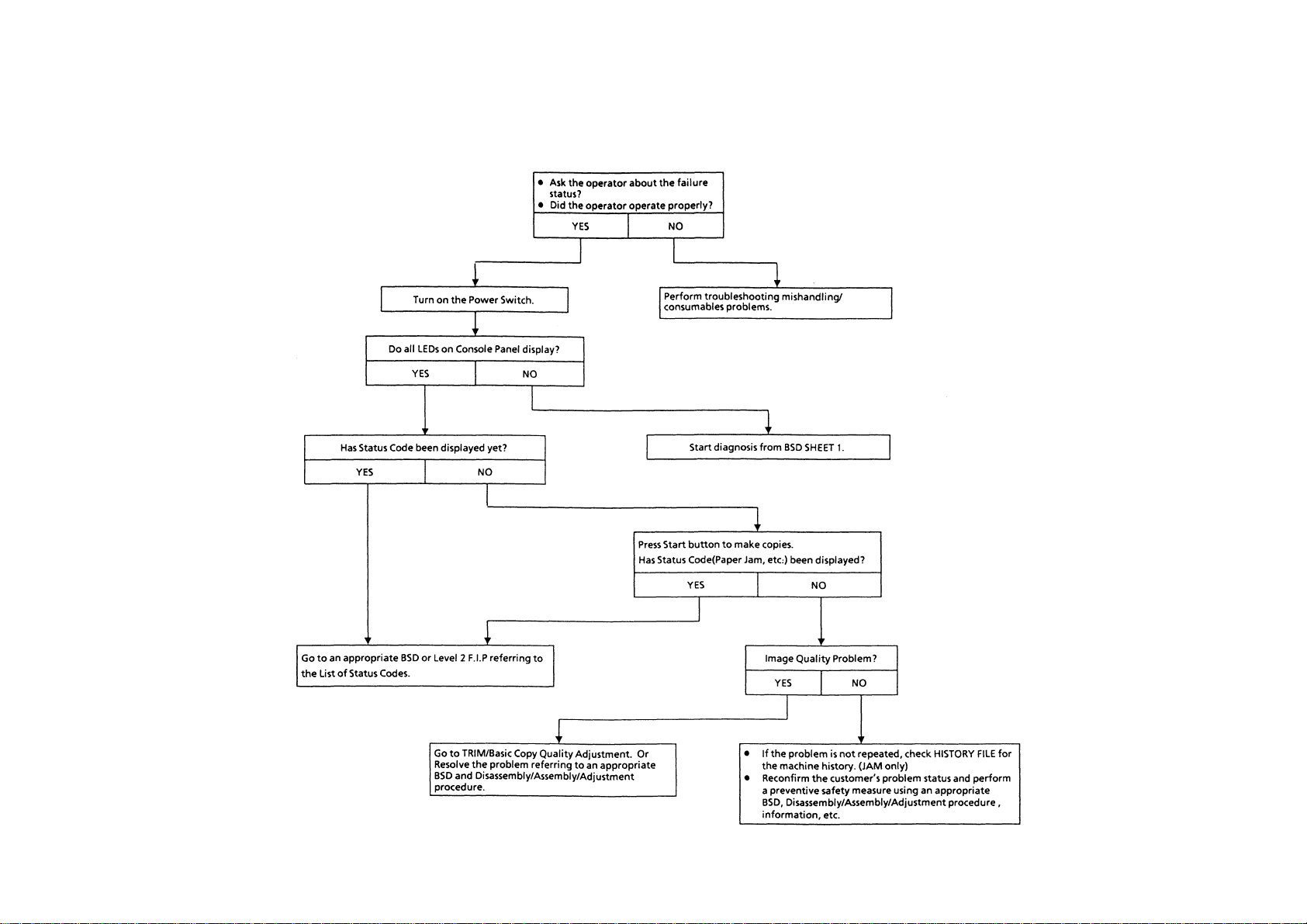
2.1.1 How to Troubleshoot
Level 1 Troubleshooting
• Level 1 Troubleshooting (Level 1 F.I.P.) is the first step
toward the diagnosis of a problem.
Level 1 F.I.P. asks you whether or not any Status Code
and other problems exist, guiding you to Level 2
Troubleshooting.
Level 2 Troubleshooting
• Level 2 Troubleshooting is a diagnostic procedure of
isolating one problem by classified Status Codes,
Misfeed Jams and various problematic symptoms.
Performing a F.I.P. or an appropriate procedure in the
check list enables you to discover causes of a problem
in a short period of time.
• Status Code
When a Status Code alerts you to a machine failure,
perform appropriate troubleshooting items, referring to
the list of Status Codes listing problem contents and
corrective actions or troublesh ooting items.
How to Troubleshoot and Notes
• First perform Level 1 F.I.P. to isolate one problem.
Then go to an appropriate Level 2 Tro ubleshooting,
BSD, or Disassembly/Assem bly/Adjustment proce du re
to resolve the problem. W hen you try to find a cause of a
problem using a F.I.P. or Check Chart, you should read
its procedure carefully and perform it properly. When
there are a number of possible causes , yo u may pe rfo rm
a F.I.P. of the same title again, because it is impossible
to find all causes at once. In this case, pay attention to
different judgments made in the process of the same
F.I.P.
• When taking voltage measurements or performing
operation tests of electric appli a nce s, you shou l d ch eat
their Interlock Switches.
• When replacing PWBs, you should check connectors on
them for proper connections before replacements.
2.1.2 Terminolog y
Troubleshooting uses the following terms. You need to understand these terms in analyzing failures.
Common Terminology
Status Code The message “Report XX.” appears when the machine discovers a problem. This XX
is called Status Code.
Actuate Mechanically press or release the Switch Actuator or the linking Mechanical Linkage.
Block Place a document or a sheet of paper against the Photo Sensor to make the Sensor
detect one.
Check Visually Check parts such as the Relay or Mechanical Linkage for its proper operation
or check to see if parts are defective.
Enter Diagnostic Mode. Enter Diagnostic Mode following the procedure indicated in Diagnostic(C/E) Mode.
Check for a short circuit. Power off. Measure the resistances between the wire and the frame with the tester
Ohm range.
Check for an open circuit Power off. Measure the resistance on the both ends of the wire with the tester Ohm
range.
Set [*.*] to ON Enter Diagnostic Mode following the procedure indicated in Diagnostic(C/E) Mode.
Then enter [Chain Code & Function Code]. Once you have entered Diagnostic Mode,
you must not exit it until you are instructed by the message to “Exit Diagnostic Mode”
or you don’t need to check any more because an area where a failure has occurred is
found.
Stop [*.*] Press the Stop button to set the drive signal for the output component being tested to
OFF.
Exit Diagnostic Mode Exit Diagnostic Mode follo wing the proce d ure described in Diagnostic Mode/Pro g ram .
Check Voltage Levels
+ 5VDC • + 5.2VDC ± 0.25VDC NOTE: The voltage values may exceed their ranges
a little due to varying AC powers or loads.
+ 24VDC • + 24VDC ± 2.4VDC
Breakaway from Failure Analysis Procedure
Mechanical Problem This is used when you should move to mechanical adjustments and parts
replacements. Read all items (describing main causes) and find causes of a problem
in comparison with symptoms the machine shows.
PL 4.2 Refer to Parts List PL 4.2, Section 5.
BSD 6 Refer to BSD 6, Section 9.
4.1.3 Refer to 4.1.3, Section 4 Disassembly/Assembly/Adjustment.
Replace parts in order When it is impossible to further analyze causes of a problem, replace parts in order.
Replacement parts are described in order of highest possible replacement items.
Page 12

Intentional blank page
2-3
Section 2 Troubleshooting
Page 13

2-4
Section 2 Troubleshooting
2.2 Diagnostic(C/E) Mode
2.2 Diagnostic(C/E) Mode
2.2.1 How to Enter Diagnostic(C/E) Mode
Power on while pressing “0” on the keyboard.
• All the LEDs on Console Panel turn on.
When you press the key pad or the Stop Clear
button, the three LEDs: “El JAM”, “E3 JAM” and
“TONER EMPTY” starts flashing while the other
LEDs turn off.
2.2.2 Entries of Chain Codes, Function
Codes and Set Values
If you enter a wrong Chain Code or Fun ction
Code, press the Stop Clear button and re-enter
a correct one.
• If you enter an unspecified Chain Code,
Function Code or Set Value, “Er” appears.
2.2.3 How to Exit Diagnostic(C/E) Mode
Set the Power to OFF/ON.
2.2.4 Diagnostic Functions & Operating
Procedures
Input Check
Function:
This displays the input voltage level from the
Sensor or the Switch with “H” or “L”
Procedure:
1. Enter Diagnostic (C/E) Mode.
2. Enter the Chain Code for a part to be
checked and press the Start but to n.
3. Enter the Function Code for a part to be
checked and press the Start but to n.
4. Operate the part to be checked.
• When the voltage level is high, “H” is
displayed. When it is low, “L” is displayed.
5. When you press the Stop Clear button once
during the check, the Function Code Entry
awaiting status is initiated, while you press it
twice, the Chain Code Entry awaiting status
is initiated.
A/D Input Check
Function:
This displays the input voltage level from the
Sensor with a digital value.
Procedure:
1. Enter Diagnostic (C/E) Mode.
2. Enter the Chain Code for a part to be
checked and press the Start but to n.
3. Enter the Function Code for a part to be
checked and press the Start but to n.
• The voltage levels are displayed with the
digital values of 0~FF.
The varying voltage level will change the
display.
4. When you press the Stop Clear button once
during the check, the Function Code Entry
awaiting status is initiated, while you press it
twice, the Chain Code Entry awaiting status
is initiated.
Console Button Check (2-1)
Function:
This checks any other button than the Stop
Clear one on the Console Panel.
Procedure:
1. Enter Diagnostic (C/E) Mode.
2. Enter Chain Code “2” and press the Start
button.
3. Enter Function Code “1” and press the Start
button.
4. Set any other button than the Stop Clear
one to ON/OFF, then + 2 is added to the
displayed value.
5. When you press the Stop Clear button once
during the check, the Function Code Entry
awaiting status is initiated, while you press it
twice, the Chain Code Entry awaiting status
is initiated.
Page 14

2.2 Diagnostic(C/E) Mode
2.2.4 Diagnostic Functions & Operating procedures
Input Check
CHAIN
FUNCTION
CODE
CODE
1 1 Front Interlock Switch H/L 1
2 RH Upper Interlock Switch H/L 5
2 1 Console Button +1 2
3 10 Option Set H/L 2
11 Option Start H/L 2
12 Option Stop H/L 2
6 1 Lens Sensor H/L 3
2 Optical Regi Sensor H/L 3
8 Exposure Monitor Sign al A/D 3
17 Fuser Thermistor A/D 7
18
7 1 Tray 1 Size Sensor H/L 5
6 Tray 1 No Paper Sensor H/L 5
10 MSI No Paper Sensor H/L 5
8 8 Regi Gate Sensor H/L 5
9 Fuser Exit Switch H/L 7
10 MSI Size Sensor H/L 5
9 9 Toner Empty Sensor H/L 7
PART/SIGNAL
Fuser Thermistor Open
Circuit
DIS-
PLAY
A/D 7
REF.
BSD
2-5 2.2 Diagnostic(C/E) Mode
Section 2 Troubleshooting
Page 15

2-6
Output Check
Function:
This operates parts such as the Solenoid, the
Clutch and the Motor. You can set parts within
the same Chain to the ON positions
simultaneously.
Procedure:
1. Enter Diagnostic(C/E) Mode.
2. Enter the Chain Code for a part to be
operated. Press the Start button.
3. Enter the Function Code and press the Start
button.
• The designated part starts operating.
4. When you operate parts simultaneously,
enter the Function Codes for the parts you
will operate successively. Press the Start
button.
5. When you stop operating a part
simultaneously, press the Stop Clear
button.
• When parts are operating, stop them
simultaneously.
• The following parts stop automatically after
respective specified periods of time:
• All Solenoids/Clutches ..... 1 sec.
• Lamp Carriage Motor ....... 1 sec.
• Exposure Lamp ................ 30 sec.
REF.: When you press the Start button
again after the above parts stop
automatically, they start operating
again.
Section 2 Troubleshooting
2.2 Diagnostic(C/E) Mode
Page 16

Output Check
CHAIN FUNCTION PART/SIGNAL
4 1 Main Motor(& Erase Lamp) 2,7
6 3 Lamp Carriage Motor(Scan) 1sec 3
4 Lamp Carri age Motor(Return) 1sec 3
7 Exposure Lamp(& Erase Lamp) 30sec 2,3,7
8 1 Main Motor (& Erase Lamp) 2,7
2 Tray 1 Feed Solenoid 5
6 Regi Gate Solenoid 5
7 MSI Feed Clutch 5
9 1 Main Motor (& Erase Lamp) 2,7
2 DEVE Bias 7
3ISIL 7
10 1 Optical Cooling Fan Motor 3
4 Fuser fan Motor 7
ON
TIME
REF.
BSD
2-7 2.2 Diagnostic(C/E) Mode
Section 2 Troubleshooting
Page 17

2-8
Section 2 Troubleshooting
2.2 Diagnostic(C/E) Mode
Parameter (NVM Value) Adjustment
Function:
This performs the Parameter (NVM Value)
Adjustment.
Procedure:
1. Enter Diagnostic(C/E) Mode.
2. Enter Chain Code “20” and press the Start
button.
3. Enter the Function Code for the parameter
to be adjusted. Press the Start button.
• The current value is displayed flashing on
the Quantity Display.
4. Enter a new set value with the key pad and
press the Start button.
• The flashing display comes to remain on.
Then the old set value has been changed
to the new one.
5. When you press the Stop Clear button
once,
the Function Code Entry awaiting status is
initiated, while you press it twice, the Chain
Code Entry awaiting status is initiated.
NVM Initialization (20-96)
Function:
This initializes all NVM contents.
Procedure:
1. Enter Diagnostic(C/E) Mode.
2. Enter Chain Code “20” and Function Code
“96.” Press the Start button.
• The Quantity is displayed as follows:
“55” →→ “Ed”
• Initialize the following NVM items:
1) Set initial values in all Functions in
Chain 20.
2) Reset alI Counters in Chains 30/40.
3) Set set-values in all Functions in Chain
50.
4) Set initial values in all programs in
Specification Setup.
3. To exit this mode, press the Stop Clear
button twice.
Page 18

Chain Code 20 Table
CHAIN
CODE
FUNCTION
CODE
20 1 Registration Adjustment 16(-4.13mm) 32 64(+4.13mm) 0.2564mm
2 Light Quantity Adj. 100% 0 30 80 0.8%
Enlargement/Reduction 0 50 99 0.8%
3 Paper Loop Amount Adjustment 0(-8.27mm) 32 64(+8.27mm) 0.2584mm
4 ISIL Lead Edge Erase Amount Adjustment 0(-8.27mm) 32 64(+8.27mm) 0.2584mm
5 ISIL Trail Edge Erase Amount Adjustment 0(-8.27mm) 32 64(+8.27mm) 0.2584mm
6 Fine Tuning of 100% Horizontal Magnification 0(-2.272%) 32 64(+2.272%) 0.071%
7 Fine Tuning of 100% Vertical Magnification 0(-3.16%) 32 64(+3.16%) 0.099%
10 MSI Paper Loop Amount Adjustment 0(-8.27mm) 32 64(+8.27mm) 0.2584mm 11 Registration Adjustment (MSI) 16(-4.13mm) 32 64(+4.13mm) 0.2564mm
14 Selection of Exposure Photoreceptor Sensitivity Correction 0(OFF) 1(ON) 1(ON) 16 Bias Curve Selection 1 0 4 8 17 Bias Curve Selection 2 0(slot) 1(Flat) 1(Flat) 20 Exposure Lamp Adj. 0 50 99
23 Drum Photoreceptor Sensitivity Correction Constant 0(0) 11(1.1) 40(4.0) 0.1 30 Fuser Temperature Adjustment (Stand-by)
31 Fuser Temp. Adjustment (Copy cycle)
41 Density Correction Light 6 0(0V) 52(-413V) 64(-500V) -7.8125V 42 Density Correction Dark 6 0(0V) 16(-125V) 64(-500V) -7.8125V 45 Density Correction Photo Light 6 0(0V) 50(-388V) 64(-500V) -7.8125V 46 Density Correction Photo Dark 6 0(0V) 24(-184V) 64(-500V) -7.8125V 96 NVM Initialization This initializes all NVM values.
50 9 Black band Function Time 1 0(-5.168mm) 20(+9.56mm) 64(+5.168mm) 0.2584mm
10 Black band Function Time 2 0(-6.732mm) 64(+10.3mm) 64(+6.732mm) 0.2584mm
SETUP ITEM MIN. VALUE INITIAL VALUE MAX.VALUE 1 STEP CHANGE ADJ
0(-23°C)
0(-23°C)
32
32
39(+5°C) 0.72°C
39(+5°C) 0.72°C
2.7.6
5.1.4-
5.1.4-
5.1.6
5.1.6
4.3.4
4.3.4
5.1.4-
-
-
2-9 2.2 Diagnostic(C/E) Mode
Section 2 Troubleshooting
Page 19

2-10
Section 2 Troubleshooting
2.2 Diagnostic(C/E) Mode
Feed Counter Check/Clearance.
Function:
This displays or clears Feed Cou nt ers for all
trays .
Procedure:
1. Enter Diagnostic(C/E) Mode.
2. Enter Chain Code “30” and press the Start
button.
3. Enter the Function Code for the Feed
Counter to be checked. Press the Start
button.
• The counter value is displayed by the unit
of k on the Quantity Display.
• When not clearing the counter value, go to
Step 5.
4. Enter “0” with the keyboard and press the
Start button.
• The counter value is cleared.
• If you enter any other value than “0, ” “Er”
appears.
5. Pressing the Stop Clear button once will
initiate the Function Code Entry awaiting
status, while pressing it twice will initiate the
Chain Code Entry awaiting status.
REF.: Counter Value is countable within the
range of 0~99k feeds, but uncount abl e
when it exceeds 99k.
CHAIN
CODE
30 1 Tray 1 Feed Counter
FUNCTION
CODE
4 MSI Feed Counter
COMPONENT
COUNTER
JAM Counter Check.
Function:
This counts Original/Paper Jams and display
their counts for every component where they
occur.
Procedure:
1. Enter Diagnostic(C/E) Mode.
2. Enter Chain Code “40” and press the Start
button.
3. Enter the Function Code for the counter to
be checked. Press the Start button.
• The counter value is displayed on the
Quantity Display.
5. To exit this mode, press the Stop Clear
button twice.
NOTE: Counter Value is countable within
the range of 0~99 feeds, but
uncountable when it exceeds 99K .
CHAIN
CODE
40 1 E1 JAM Counter
FUNCTION
Jam Counter Reset.
Function:
This clears Original/Pap er Jam Count ers.
Procedure:
1. Enter Diagnostic(C/E) Mode.
2. Enter Chain Code “40” and press the Start
button.
3. Enter the Function Code for the counter to
be checked. Press the Start button.
4. To exit this mode, press the Stop Clear
button twice.
CODE
2 E3 JAM Counter
5 C1 JAM Counter
10 C9 JAM Counter
21 E1 JAM Counter Reset
22 E3 JAM Counter Reset
25 C1 JAM Counter Reset
30 C9 JAM Counter Reset
COMPONENT COUNTER
Page 20

Individual Mode Setup
Function:
This sets up the execution/ inhibition of certain
functions for individual users.
Procedure:
1. Enter Diagnostic(C/E) Mode.
2. Enter Chain Code “50” and press the Start
button.
3. Enter the Function Code for the mode
(function) to be set up. Press the Start
button.
• The present value appears on the
Quantity Display.
• When not changing the set value, go to
Step 5.
4. Enter a new set value with the key pad and
press the Start button.
• The old set value is rewritten into the new
one.
5. Pressing the Stop Clear button once will
initiate the Function Code Entry awaiting
status, while pressing it twice will initiate the
Chain Code Entry awaiting status.
U4-6 Failure Clearance
Function:
When U4-6(Fuser Over Heat Fail) occurs,
clear U4-6 by executing [50-20] in Diagnostic
(C/E) Mode.
Procedure:
1. Open the Front Interlock and enter
Diagnostic(C/E) Mod e.
NOTE: During the occurrence of U4-6, you
cannot enter Diagnostic (C/E ) Mo de
2. Enter Chain Code “50” and press the Start
3. Enter Function Code “20” and press the
4. Close the Front Interlock.
5. Set the power to OFF/ON.
without opening the Front Interlock.
button.
Start button.
• The Quantity Display displays “Ed”
indicating the clearance is complete.
U8-7 Failure Clearance
Function:
When U8-7(Exposure Lamp mistakenly turns
on) occurs, clear U8-7 by executing [50-21] in.
Diagnostic(C/E) Mod e.
Procedure:
1. Open the Front Interlock and enter
Diagnostic(C/E) Mod e.
2. Enter Chain Code “50” and press the Start
button.
3. Enter Function Code “21” and press the
Start button.
• The Quantity Display displays “Ed”
indicating the clearance is complete.
4. Close the Front Interlock.
5. Set the power to OFF/ON.
CHAIN
CODE
50 1
FUNCTION
CODE
2 Nation Configuration Setup
4
6
7 Fuser Warm Up Function
8 Copy density selection
9
10
20
21
86
SETUP ITEM
Toner Touch Up Function
Black Band Creation
Function
Related Products’ L6
Detection
Black Band Function
Time1
Black Band Function
Time2
Fuser Over Heat Failure
Clearance
Exposure Lamp Failure
Clearance
Machine Administrator
Reset
SET
VALUE
CONTENT EXPLANATION
0 inhibit
*1 execute
0XE
1KX
*2 AP
Execute
0
*1 Execute
2execute
3 inhibit
*0 No
1Yes
*0 Inhibit
1execute
0 13Phase
*1 7Phase
0~40 20
0~40 20
Cancellation
0
Cancellation
1
Cancellation
0
Cancellation
1
- - Set to “1111”.
Only when the new Drum
unit is installed, this sets
up Toner Touch Up
Function at the start of
copying to prevent Talc
Deletion.
This supplements a lack of
exposure light quantity by
the Deve. Bias when it
doesn’t reach its target
value.
Create a black band of
Toner on the Drum to
prevent Talc Deletion.
This temporarily inhibits
the detection of L6 when
changes are made to
specification setups of the
machine with related
products.
At the start of an initial
copy with the power on,
this warms up the Fuser
by rotating the Main Motor
for 20 sec .
In case of KX
In case of AP
U4-6(Fuser Over Heat
Fail) will be cleared.
U8-7(Exposure Lamp
mistakenly turns on) will
be cleared.
NOTE: Set Value with * indicates that the value is its initial one at the execution of [20-96] .
2-11 2.2 Diagnostic(C/E) Mode
Section 2 Troubleshooting
Page 21
2-12
2.3 Level 1 Troubleshooting
2.3.1 Level 1 F.I.P
Section 2 Troubleshooting
2.3 Level1 Troubleshooting
Page 22

2.3.2 Chart of JAM Status Codes
Machine
OFF CHECK
E3-3
E3-6
FUSER EXIT SW
TRA Y 1
E1-1
ON CHECK
JAM
JAM
STA TIC
JAM
E1-2
E1-6
C9-3
REGI GATE SNR
OFF CHECK
JAM
STA TIC
JAM
MSI MISS
FEED JAM
C1-3
C1-2
2-13 2.3 Level 1 Troubleshooting
Section 2 Troubleshooting
Page 23

2-14
2.3.3 Status Code List
Section 2 Troubleshooting
2.3 level 1 Troubleshooting
STATUS
CODE
U1-1 M/C CLOCK FAIL M/C clock fails to input the signal to Main PWB even once for 0.47 sec., while copying
U2-1 LAMP CARRIAGE FAIL-STAND-BY Lamp carriage doesn’t actuate Optical Registration Sensor for 6.5 sec., during stand-by.
U2-2 LAMP CARRIAGE FAIL-POSITION
U2-3 LAMP CARRIAGE FAIL-SCAN Optical Registration sensor isn’t turned on within 0.46 sec., after Lamp Carriage starts scanning.
U2-4 LAMP CARRIAGE FAIL-RETURN Optical Registration sensor isn’t turned on within 2.5 sec., after Lamp Carriage starts scanning.
U3-1 LENS POSITION FAIL
U4-1 FUSER THERMISTOR OPEN FAIL Open or defective circuit of Fuser Thermistor
U4-2 FUSER WARM UP FAIL Fuser Ready is not initiated within 1 min. After the power is on or Front interlock Switch is turned OFF/ON.
U4-3 FUSER OVER HEAT FAIL 1 Heater Rod has been on for 10 sec. or more after Fuser Ready
U4-4 FUSER OVER HEAT FAIL 2 Heater Rod has been on for 20sec. or more after Cycle Down
U4-6 FUSER OVER HEAT SAFETY FAIL
U6-4 NVM FAIL NVM READ/WRITE VERIFY ERROR
U8-1 EXPOSURE CONTROL FAIL Control Mode is not initiated within 0.5 sec., after Exposure Lamp turns on.
U8-2 NO ZERO CROSS FAIL During Fuse Control, no Zero Cross is input for straight 3 sec.
U8-4
U8-5
EXPOSURE VOLTAGE OVER
FAIL
EXPOSURE VOLTAGE UNDER
FAIL
NAME PROBLEM CORRECTIVE ACTION
1: Optical Registration Sensor isn’t turned on within 0.05 sec., after the initial operation
of Lamp Carriage after copying is finished.
2: Optical Registration sensor isn’t turned on within 0.05 sec., after the start of copying.
Lens Sensor isn’t turned on within 3.1 sec., after the initial operation of Lens.
(i.e. Lens starts moving)
Fuser Thermistor has detected 240°C or a higher temperature for straight 0.5sec. or more • Enter Diagnostic(C/E) Mode and execute [5-20]
Exposure Sensor signal voltage level is over 2.9V when Exposure Lamp is on.
Exposure Sensor signal voltage level is under 0.5V at Standard Reflection Plate.
• Refer to the U-Code F.I.P.
• Refer to the U-Code F.I.P.
• Refer to the U-Code F.I.P.
• Refer to the U-Code F.I.P.
• Refer to the U-Code F.I.P.
• Refer to the U-Code F.I.P.
• Refer to the U-Code F.I.P.
• Refer to the U-Code F.I.P.
• Refer to the U-Code F.I.P.
• Refer to the U-Code F.I.P.
• Refer to the U-Code F.I.P.
• Refer to the U-Code F.I.P.
• Refer to the U-Code F.I.P.
• Refer to the U-Code F.I.P.
• Refer to the U-Code F.I.P.
REF.
BSD
2
3
3
3
3
3
5
5
5
5
5
2
3
5
3
3
Page 24

STATUS
CODE
C1-2 TRAY 1 MIS FEED JAM Regi-gate Sensor isn’t turned on within 2.7sec. after paper starts to be fed.
C9-3 MSI MISFEED JAM Regi-gate Sensor isn’t turned on within 2.3 sec. after paper starts to be fed.
E1-1 FUSER EXIT SWITCH ON CHECK JAM Fuser Exit Switch isn’t turned on within 3.7 sec. After Regi-Gate is open.
E1-2 REGI-GATE SENSOR OFF CHECK JAM
E1-6 REGI-GATE SENSOR STATIC JAM Regi-Sensor is on during Power On or Stand-by. (Paper remains)
E3-3 FUSER EXIT SWITCH OFF CHECK JAM
E3-6 FUSER EXIT SWITCH STATIC JAM Fuser Exit Switch is on during Power On or Stand-by. (Paper remains)
E5-1 FRONT INTLK OPEN FAIL Front Cover is open, or Front Interlock Switch is defective.
E6-1 R/H UPPER INTLK OPEN FAIL R/H Upper Cover is open, or R/H Upper Interlock Switch is defective.
J1-1 TONER EMPTY FAIL Number of copies reaches 100 after toner empty sensor sensed toner end condition.
J1-2 TONER LIFE END The counter value of toner unit reaches the default value 7700.
J3-1 DRUM UNIT SET FAIL Drum unit is not set, or is set incorrectly to the machine.
J3-2 Toner Cartridge SET FAIL Toner unit is not set, or is set incorrectly to the machine.
J3-3 Counter SET FAIL Total counter is corrected improperly.
J6-1 DRUM UNIT ID FAIL Drum unit Read/Write is in error.
J6-2 Toner Cartridge ID FAIL Toner unit Read/Write is in error.
J6-3 Counter ID FAIL Total Counter Read/Write is in error.
J7-1 DRUM UNIT LIFE END Copy Value has become 50K (sheets of paper)
J8-1 DRUM UNIT TYPE NO. FAIL Type No. stored in ID of Drum Unit is not the same as that stored in NVM of the Main PWB.
J8-2 Toner Cartridge TYPE NO. FAIL Type No. stored in ID of Toner Unit does not match with that saved in NVM on main PWB.
J8-3 Counter TYPE NO. FAIL Type No. stored in ID of Total Counter does not match with that saved in NVM on main PWB.
J9-1
J9-2
J9-3
DRUM UNIT ID No. FAIL
TONER UNIT ID No. FAIL
TOTAL COUNTER ID No. FAIL
NAME PROBLEM CORRECTIVE ACTION
Regi-Gate Sensor isn’t turned off (remains ON) a preset period of time (which varies with paper
sizes) after Regi-Gate is open.
Fuser Exit isn’t turned off (remains ON) a preset period of time (which varies with paper sizes) after
Fuser Exit Switch is turned on.
Identification No. of Drum Unit is not of Xerox origin.
Identification No. of Toner Unit is not of Xerox origin.
Identification No. of Total Copy Count is not of Xerox origin.
• Refer to the MISFEED JAM.
• Refer to the MISFEED JAM
• Refer to BSD Sheet 5
• Refer to BSD Sheet 5
• Remove the paper
• Check the Regi-Gate sensor circuit.
• Refer to BSD Sheet 5
• Remove the paper
• Check the Fuser Exit Switch circuit.
• Close Front Cover.
• Check the Front Interlock Switch circuit.
• Check R/H Upper Cover.
• Check the R/H Upper Interlock switch circuit.
• Supply toner.
• Check the Toner Empty Sensor circuit.
• Replace the Toner Cartridge.
• Ensure to install the Drum Unit to the machine
• Ensure to install the Toner Unit to the machine
• Ensure to install the Total Copy Count Unit to
• Replace the Drum Unit.
• Replace th e Toner Unit.
• Replace the Total Copy Count Unit.
• Replace the Drum Unit.
• Replace with correct type Drum Unit
• Replace with correct type Toner Unit
• Replace with correct type Total Copy Count
Unit
• Replace with Xerox Drum Unit
• Replace with Xerox Toner Unit
• Replace with Xerox Total Copy Coun t Unit
REF.
BSD
4
4
5
5
4
5
5
4
4
5
5
5
5
5
5
5
5
5
5
5
5
5
5
5
2-15 2.3 Level 1 Troubleshooting
Section 2 Troubleshooting
Page 25
2-16
2.4 Level 2 Troubleshooting
2.4.1 General F.I.P (General F.I.P for Defective Parts)
Section 2 Troubleshooting
2.4 level 2 Troubleshooting
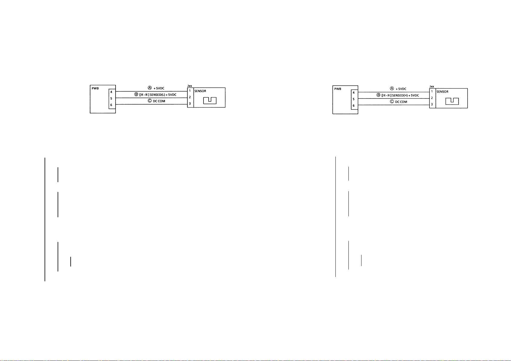
•••• Reflective Sensor F.I.P [SENSED(L)]
ORIGINAL SIZE Sensors 1~4
Preparation: • Remove any remaining paper (if there is any).
Procedure
Enter Diag. [
Make the Sensor turn ON/OFF with a blank sheet of paper.
Does the display repeat (L) and (H) alternately ?
YN
٭ - ٭ ].
Does the display remain (H)?
YN It remains (L).
Check with the tester the harness from Pin 2 of the
Sensor to Pin 5 of PW B for a short circuit. If it is good,
replace the Sensor.
Can the tester lead wire be inserted in Jxx of the Sensor ?
YN
Check Pins 4/5/6 for improper connections or
Harnesses ○
replace the Sensor.
A ○B ○C
for open circuits. If they are good,
٭ You can also check by exchanging the Sensor with
another Sensor of the same type if one is available.
Place the tester wire between Pin 2(+) of the Sensor and
COM(–) .
Make the Sensor turn ON/OFF with blank paper.
Does the voltage repeat (L) and (H) alternately?
YN
Is the voltage from Pin 1(+) to Pin 3 of the Sensor
+5VDC?
YN
Check Pins 4/6 for improper connections or
Harnesses ○
Replace the Sensor.
Check to see if the document detecting position on Platen
Glass is contaminated. If not, replace the PW B.
Check outer light/check the sensor for its installation and (signal)
chattering. If no problem exists, replace the PWB.
A ○C
for open circuits.
••••
•••• Permeable Sensor F.I.P [SENSOR(H)]
OTHER SENSORs with 3
Wiring
Preparation: • Remove any remaining paper (if there is any).
Procedure
Enter Diag. [
Make Actuator turn ON/OFF manually or with paper. (If necessary,
use Output Check.)
YN
٭ – ٭ ].
Does the display remain (H)?
YN It remains (L).
Check with the tester the harness ○
Sensor to Pin 5 of PW B for a short circuit. If it is good,
replace the Sensor.
Can the tester lead wire be inserted in Jxx of the Sensor?
YN
Check Pins 4/5/6 for improper connections or
Harnesses ○
replace the Sensor.
A ○B ○C
for open circuits. If they are good,
B
from Pin 2 of the
٭ You can also check by exchanging the Sensor with
another Sensor of the same type if one is available.
Place the tester wire between Pin 2(+) of the Sensor and
COM(–) .
Make Actuator turn ON/OFF manually or with paper.
Does the voltage repeat (L) and (H) alternately?
YN
Is the voltage from Pin 1(+) to Pin 3 of the Sensor
+ 5VDC?
YN
Check Pins 4/6 for improper connections or
Harnesses ○
Replace the Sensor.
Replace the PWB.
Check the Sensor for its installation and (signal) chattering. If no
problem exists, replace the PWB.
A ○C
for open circuits.
Page 26

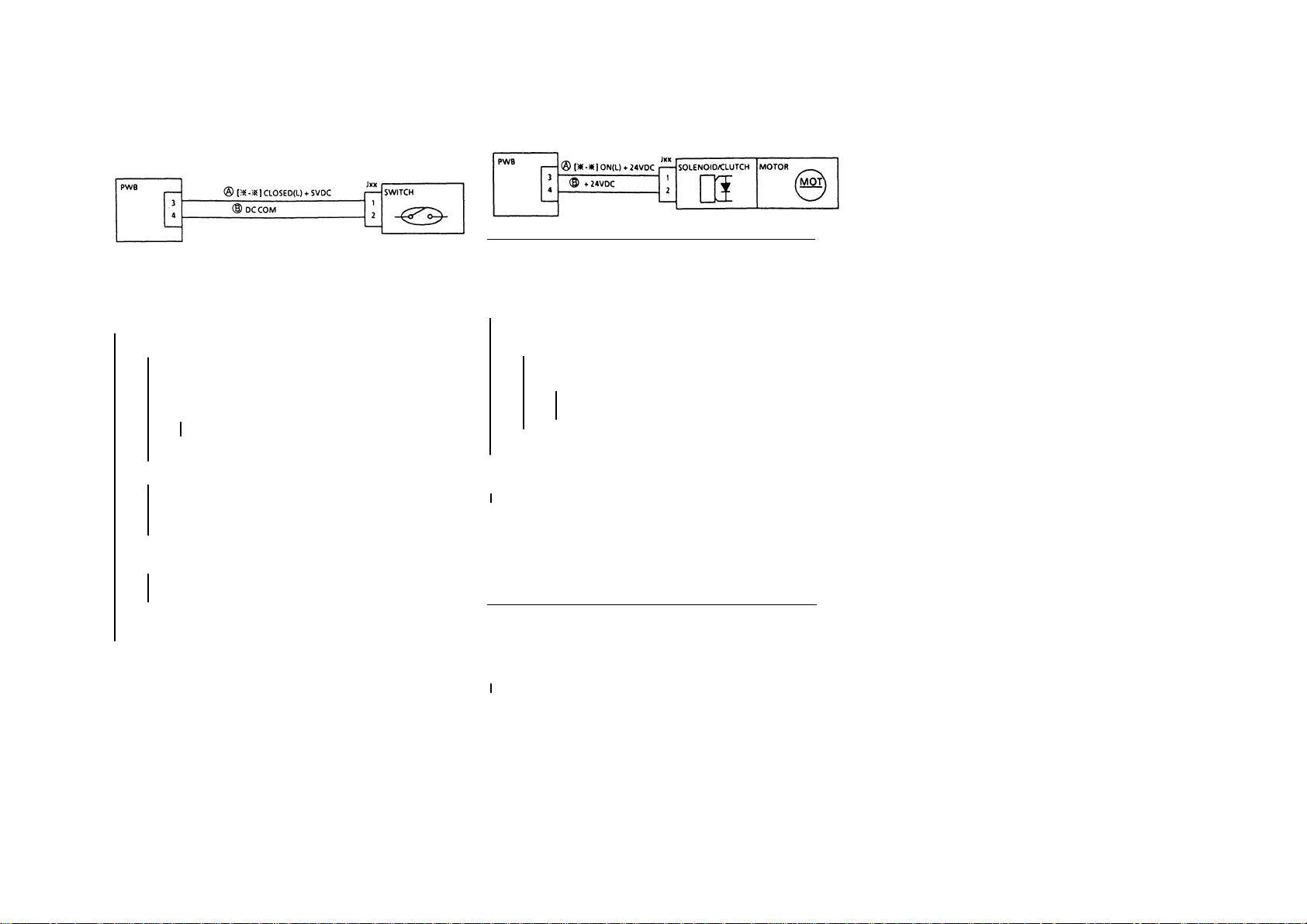
• Switch F.I.P
PLATEN INTLK SWITCH
R/H UPPER INTLK SWITCH
Procedure
Enter Diag. [
Make the Switch turn ON/OFF(Cover open/close). If necessary, use
Output Check.
Does the display repeat (L) and (H) alternately?
YN
٭ - ٭ ].
Does the display remain (H)?
YN It remains (L).
Turn the power off.
Disconnect Connector Jxx of the Switch.
Enter Diag. [
Does the display remain (L)?
YN The display has been changed to(H)
Check shorted areas(i.e. a wire caught in the frame) of
Harness ○
Can the tester lead wire be inserted in Jxx of the Switch?
YN
Check Harnesses A, B for open circuits. If they are
good, replace the S witch.
٭ - ٭ ].
Replace the Switch.
A
and repair them.
٭ You can also check by exchanging the Switch with
another Switch of the same type if one is available.
Is the voltage from Pin 1(+) to COM +5VDC with the Switch
off?
YN(0V)
Check Pin 1 of the Switch or Pin 3 of PWB for an
improper connection or Harness ○
Check Pin 2 of the S witch for an improper connection or
B
Harness ○
Switch.
Check the Panel, etc. for end play or recheck Switch Leads 1/2. If no
problem exists, replace PWB.
for an open wire. If no problem exists, replace the
A
for an open circuit.
• Solenoid/Clutch/Motor F.I.P
1. Solenoid or Clutch doesn’t energize. Motor doesn’t rotate.
Procedure
Enter Diag. [
Don’t start.)
Is the voltage from Pin 3(+) of PWB to COM(–) +24VDC?
YN
Start (or Actuate).
Has Power level dropped to (L)?
YN It remains (H).
Repair the binding Plunger or clear the inside of the Solenoid of
contamination. Don’t clean the Clutch.
If necessary, replace the Solenoid/Clutch/Motor.
2. Solenoid/Clutch keeps energized. Motor keeps rotating.
Procedure
Power off.
Is the resistance value from Connector Pin 3 of PWB to the frame
0~some hundred
YN (~)
Repair shorted areas of the circuit from Connector Pin 3 to Pin 1 of
Solenoid/Clutch/Motor. If no problem(such as a wire caught in the
frame) exists, replace the Solenoid/Clutch/Motor.
٭ - ٭]. (NOTE: All you have to do here is enter Diag.
Is the voltage from Pin 1(+) of Solenoid/Clutch/Motor to GND
(–) +24VDC?
YN
Is the voltage from Pin 2(+) of Solenoid/Clutch/Motor to
GND(–) +24VDC?
YN
Go to 1. STANDBY POWER, BSD to check DC
power(+24VDC).
Replace the Solenoid/Clutch/Motor.
Check the circuit from Pin 3 of PWB to Pin l Solenoid/Clutch/
Motor for an improper connection/open circuit.
Replace the PWB.
Ω?
Replace the PWB.
2-17 2.4 Level 2 Troubleshooting
Section 2 Troubleshooting
Page 27
2-18
Section 2 Troubleshooting
2.4 Level 2 Troubleshooting
• Switch F.I.P
R/H UPPER INTLK SWITCH
Procedure
Enter Diag. [
Make the Switch turn ON/OFF(Cover open/close). If necessary, use
Output Check.
Does the display repeat (L) and (H) alternately?
YN
٭ - ٭ ].
Does the display remain (H)?
YN It remains (L).
Power off.
Disconnect Connector Jxx of the Switch.
Enter Diag. [
Does the display remain (L)?
YN The display has been changed to(H)
Check shorted areas(i.e. a wire caught in the frame) of
Harness ○
Can the tester lead wire be inserted in Jxx of the Switch?
YN
Check Harnesses A B for open circuits. If they are
good, replace the S witch.
٭ - ٭ ].
Replace the Switch.
A
and repair them.
٭ You can also check by exchanging the Switch with
another Switch of the same type if one is available.
Is the voltage from Pin 1(+) to COM +5VDC with the Switch
off?
YN(0V)
Check Pin 1 of the Switch or Pin 3 of PWB for an
improper connection or Harness ○
Check Pin 2 of the S witch for an improper connection or
B
Harness ○
Switch.
Check the Panel, etc. for end play or recheck Switch Leads 1/2. If no
problem exists, replace PWB.
for an open wire. If no problem exists, replace the
A
for an open circuit.
• Solenoid/Clutch/Motor F.I.P
1. Solenoid or Clutch doesn’t energize. Motor doesn’t rotate.
Procedure
Enter Diag. [
Don’t start.)
Is the voltage from Pin 3(+) of PWB to COM(–) +24VDC?
YN
Start (or Actuate).
Has Power level dropped to (L)?
YN It remains (H).
Repair the binding Plunger or clear the inside of the Solenoid of
contamination. Don’t clean the Clutch.
If necessary, replace the Solenoid/Clutch/Motor.
2. Solenoid/Clutch keeps energized. Motor keeps rotating.
Procedure
Power off.
Is the resistance value from Connector Pin 3 of PWB to the frame
0~some hundred
YN (~)
Repair shorted areas of the circuit from Connector Pin 3 to Pin 1 of
Solenoid/Clutch/Motor. If no problem(such as a wire caught in the
frame) exists, replace the Solenoid/Clutch/Motor.
٭ - ٭]. (NOTE: All you have to do here is enter Diag.
Is the voltage from Pin 1(+) of Solenoid/Clutch/Motor to GND
(–) +24VDC?
YN
Is the voltage from Pin 2(+) of Solenoid/Clutch/Motor to
GND(–) +24VDC?
YN
Go to 1. STANDBY POWER, BSD to check DC
power(+24VDC).
Replace the Solenoid/Clutch/Motor.
Check the circuit from Pin 3 of PWB to Pin l Solenoid/Clutch/
Motor for an improper connection/open circuit.
Replace the PWB.
Ω?
Replace the PWB.
Page 28

2.4 Level 2 Troubleshooting
2.4.2 U-Code F.I.P’s
U1-1 M/C CLOCK FAIL
Ref. BSD: 2
Preparation: Ensure that the following connector is securely
Open the Front Cover and cheat the Front Interlock. Enter Diag.
(C/E) Mode. Enter Code[4 -1] and rot ate the Main Motor.
Does the Main Motor keep stoppi ng?
YN
Y N
disconnect the power cord.
power cord
connected.
• P/J404 of Main PWB
Procedure
Does the Main Motor stop after rotatin g for 1-2 seconds?
YN
Open the ClamShell and rest art the Main Mo tor .
Do abnormal noises occur or does the Main Motor
rotate irregularly?
WARNING: Pow er off the machi ne an d
Check the mechanics (Gear, Bearing, etc.) of
the following and replace parts if necessary.
Fuser Assy(PL8.4)
Regi. Roller Gear(PL2.7)
Slide out the Drum Unit and restart the Main Motor.
Do abnormal noises occur or does the Main Motor
rotate irregularly?
YN
Check the Drum Unit for its drive mechanics. If
any load or abnormal noise exists, replace the
Drum Unit.
WARNING: Power off the machine an d disco nn ect the
Check the mechanics(Gear, Bearing, etc.) of the
following and replace parts if necessary.
Deve Assy(PL6.2)
Main Drives(PL1.1/1.2/1.3)
AB
A B
Is the voltage from J404-5 of Main PWB to COM +5VDC?
YN
order.
Is the voltage from J404-1of Main PWB to COM +24VDC?
YN
Is the voltage from J404-3 of Main PWB to COM +5VDC?
YN
Is the voltage from J404-6 of Main PWB to COM +5VDC?
YN
Replace the Main Motor .
Replace the Main Motor(PL1.1/1.2)/Main PWB(PL9.1) in
Replace the Main PWB.
Check +24VDC circuit in the DC Wiring Diagram.
Check +5VDC circuit in the DC Wiring Diagram.
Replace the Main PWB.
2-19 2.4 Level 2 Troubleshooting
Section 2 Troubleshooting
Page 29

2-20
Section 2 Troubleshooting
2.4 level 2 Troubleshooting
U2-1 LAMP CARRIAGE FAIL-STAND-BY
U2-2 LAMP CARRIAGE FAIL-POSITION
U2-3 LAMP CARRIAGE FAIL-SCAN
U2-4 LAMP CARRIAGE FAIL-RETURN
REF. BSD: 3
Preparation: Ensure that the following connectors are securely
• Gently move the Lamp Carriage fro and back by
hand, Check it for the mechanical jam.
• Ensure that the following Connectors are securely
connected.
Procedure
Power on, enter Diag. Mode and enter (6-3). Press the start button.
Does the Lamp Carriage scan?
YN
Are voltages from P/J 405-7,P/J 405-8 to COM +24VDC?
Replace the Main PWB.
Enter [6-4] and press the start button.
Does the Lamp Carriage return?
Y N
Replace the Main PW B.
Using the Permeable Sensor F.I.P., General F.I.P. and the wiring
diagram, perform the diagnosis of Optical Regi Sensor. If no problem
exists, replace the Main PWB.
connected.
• P/J404 of Main PWB.
• P/J405 of Lamp Carriage Motor.
• Check the Scan Cable for disengagement, binding,
load, etc.
YN
Check +24VDC INTLK circuit.
Power off and disconnect P/J 605.
Are J605-1 to -3,J605-1 to-4, J605-2 to -5,J605-2 to -6
resistance values approx. 6.3Ω each?
YN
Replace the Lamp Carriage Motor.
U3-1 LENS POSITION FAIL
Ref. BSD: 3
Preparation: Ensure that the following connectors are securely
Procedure
Power on.
Does the Lens Assy move?(Does it perform its initial operation?)
YN
Check +24VDC circuit
Power off and disconnect P/J604.A re J604-1 to - 3,J604-1 to
-5,J604-2 to -4,J604-2 to -6 resistance values approx. 100Ω
each?
Check P405-3,4,5,6 of Main PWB and P604-3,4,5,6 of
Lens Motor for an open circuit or a short circuit to
ground.
If the harness is good, replace the lens Motor.
Replace the main PWB.
Using the Permeable Sensor F.I.P., General F.I.P. and the wiring
diagram, perform the diagnosis of Lens Sensor. If no problem exists,
replace the Main PW B.
connected.
• P/J405 of Main PWB
• Relay Connector P/J604 of Lens Motor
•
Remedy the mechanical jam
Check the Lens Cable for disengagement, binding,
•
load, etc.
Are voltages from P/J 405-1,P/J 405-2 to COM +24VDC?
Y N
YN
Page 30

U4-1 FUSER THERMISTOR OPEN FAIL
Ref. BSD: 7
Preparation: Ensure that the following connectors are securely
Procedure
WARNING: Power off the machine an d disco nn ect the
power cord.
WARNING: Fuser surfaces are hot, allow the fuser to cool down
before attempting service procedure. Fuser lubricant can cause
discomfort to eyes. Do not allow fuser lubricant to touch eyes
Disconnect P/J118.
Measure the resistance from J118-1 to J118-2.
• Fuser is hot: approx. 13k
• Fuser is cool: approx. 236kΩ
Does the resistance value satisf y the above sp ec. ?
YN(∞)
P/J118-2 to P/J410-4. If no problem exists, replace the Fuser
Replace the Main PWB.
connected.
• P/J410 of Main PWB
• P/J118 of Fuser Thermistor
Ω
Check the wire from P/J118-1 to P/J410-3, and the wire from
Thermistor.
U4-2 FUSER WARM UP FAIL
Ref. BSD: 7
Preparation: Ensure that the following connectors are securely
NOTE: This is sometimes displayed when C/E visits the customer
Procedure
WARNING: Power off the machine an d disco nn ect the
power cord.
connected.
• P/J410 of Main PWB
• P/J430/T111/T110 of AC Drive PWB
• P/J 12/13 of Main Heater Rod
• Relay Connector P/J14
and switches the m/c on after the power has been off after the
occurrences of U4-3, U4-4 & U4-6.
Therefore, the diagnosis of Thermostat is first performed.
WARNING: Fuser surfaces are hot, allow the fuser to cool
down before attempting service procedure. Fuser lubricant
can cause discomfort to eyes. Do not allow fuser lubricant to
touch eyes
Remove the Fuser Cover.
Is there continuity between the Fuser Thermostat leads?
Y N(∞)
Press the Manual Reset button of the Fuser Thermostat.
Is there continuity between the Fuser Thermostat leads?
Y N
Disconnect J12/J13 of Heater Rod?
Is there continuity between J12 and J13?
Y N
Remove the Fuser Cover.
Cheat the Front Interlock Swit ch.
Power on.
Does the Main Heater Rod turn on?
Y N
Y N
Replace the Fuser Thermostat. Proceed with the
diagnosis using U4-3/U4-4/U4-6 Over Heat FIPs.
Proceed with the diagnosis using U4-3/U4-4/U4-6 Over Heat
FIPs.
Replace the Heater Rod.
Is the voltage form T110 to T111 of AC Drive PWB 220VAC?
ABC
Is the voltage from P410-11 of Main PWB to COM
+ 24VDC?
YN
Is the voltage from P410-12 of Main PWB to COM
+ 24VDC?
Check 220VAC circuit.
Is the voltage between Relay Connectors P/J14-1 and -2
220VAC?
Y N
Check the wire from P/J14-1 to P/J12.
Check the wire from P/J14-2 to P/J13.
Power off.
Check for the scraped Heat Roll surface, the raised-off Fuser
Thermistor, the deteriorated Heater Rod. If no problem exists, replace
the Fuser Thermistor.
Replace the AC Drive PWB.
YN
Replace the AC Drive PWB.
Check the wire from P/J14-1 to T111 of AC DRIVER.
Check the wire from P/J14-2 to T110 of AC DRIVER.
A B C
2-21 2.4 Level 2 Troubleshooting
Section 2 Troubleshooting
Page 31

2-22
U4-3 FUSER OVER HEAT FAIL 1
U4-4 FUSER OVER HEAT FAIL 2
U4-6 FUSER OVER HEAT SAFETY FAIL
Ref. BSD: 7
NOTE: At the occurrence of U4-6, open the Front Cover, enter
Diagnostic(C/E) Mod e and clea r U4-6 by exe cuting [50-20].
Procedure
Power on. Check the starting signal of Fuser. Does the level between
P/J410-12 to COM remain low(L)?
YN
WARNING: Power off the machine and disconnect the
power cord.
WARNING: Fuser surfaces are hot, allow the fuser to cool
down before attempting service procedure. Fuser lubricant can
cause discomfort to eyes. Do not allow fuser lubricant to touch
eyes
Disconnect P/J14.
Check the circuit continuity from T111 to T110. (AC DRIVER)
Y N
Replace the AC Drive PWB.
Replace the Main PWB.
Check the following harnesses for short circuits.
• from P/J12 to COM.
• from P/J13 to COM.
Section 2 Troubleshooting
2.4 level 2 Troubleshooting
Page 32

U6-4 NVM FAIL
Ref. BSD: 2
Preparation: • Install th e gro und wire.
Procedure
Power OFF/ON.
Has the display of Status Code disappeared?
YN
Enter Diag.(C/E) Mode.
• Ensure that the power voltage hasn’t dropped 10%
or more (with Power ON or Power OFF).
• Ensure that there is neither operating power
sources nor devices generating high frequencies
around the installation site.
• Ensure that no high voltage wires such as the Corotron
have burnt out or have leakage.
Enter [20-96] and press the Start button.
Power OFF/ON.
Has the display of Status Code disappeared?
YN
Replace the Main PWB.
Make copies. Confirm that the machine operates properly and
monitor the machine operation for several days.
If the problem reoccurs, replace the Main PWB.
2-23 2.3 Level 1 Troubleshooting
Section 2 Troubleshooting
Page 33

2-24
Section 2 Troubleshooting
2.4 level 2 Troubleshooting
U8-1 EXPOSURE CONTROL FAIL
Ref. BSD: 3
Problem Area: Initial Light Quantity Control(Optics)
Cause/Corrective Action
• Defective Main PWB
• Defective AC Drive PWB
• Open harnesses or improper P/J connections of the circuits
controlling the above PWB’s.
U8-2 NO ZERO CROSS FAIL
Ref. BSD: 7
Preparation: Ensure that P/J410 of Main PWB is securely
WARNING: Hazardous voltage. Use extreme care.
Procedure
Power on. Detect the zero cross signal.
Is the level from P/J410-9 to COM +0.5VDC?
connected to P/J430 of AC Drive PWB.
Y N
Is the voltage from P/J437-1 to P/J437-2 220VAC?
Y N
Check 220VAC input circuit.
Is the Front INTLK switch close?
Is the voltage from J431 to COM +24VDC?
Y N
Check the trouble chain E5.
Check the start signal of the INTLK Power Relay.
Is the level from P/J410-11 to com 0v?
Y N
Replace the Main PWB.
Check the wire from P/J430-4 of AC DRIVER to P/J410-11 of
Main PWB for an open circuit, short circuit or improper
connection. If no problem exists, replace the Main PWB
Replace the Main PWB.
U8-4 EXPOSURE VOLTAGE OVER FAIL
Ref. BSD: 3
Problem Area: Light Quantity/Voltage Control(Optics)
Procedure
check the wire from P/J430-1 of AC DRIVER to P/J410-10 of Main
PWB.
Power on. Detect the Exposure Sensor Signal level.
Is the level from P/J410-10 to COM over 2.9VDC?
Y N
Replace Main PWB.
Replace AC DRIVER.
U8-5 EXPOSURE LIGHT QTY/VOLTAGE UNDER FAIL
Ref. BSD: 3
Problem Area: Light Quantity/Voltage Control(Optics)
Preparation: Ensure that P/J410-10 of Main PWB is securely
connected to P/J430-1 of AC Drive PWB.
Procedure
Enter Diag. Mode. Enter [6-7],[6-8].
Check the A/D value, A5-A7.
Is the voltage from P/J430-1 to COM ≤ 0.5V?
Y N
Replace the Main PWB.
Replace the AC DRIVER.
Page 34

2.4.3 MISFEED JAM
C1-3 TRAY 1 MISFEED JAM
Preparation:
• Ensure that no paper jam occurred.
• Ensure that the Feed Roller has not worn out and the friction is
proper.
Procedure
Clear paper jam, start copying.
Does the Feed Roller rotate?
Y N
Enter Diag. (C/E) Mode. Enter [8-2], and check the operation
of Feed Solenoid.
Y N
Check the start signal of Feed Solenoid. Does the
voltage from P/J406-10 to com go high correctly?
Y N
Replace the Main PWB
Remedy the mechanical jam, then check the
operation of Solenoid. If it cannot turn on, replace it.
Check the tension of the pick up gear spring. If the tension is
weak, replace the spring.
Clean the Feed Roller and the Pinch Roller, Check them for the
deterioration.
Y N
Did the lead edge of paper reach the Regi-Gate.
Y N
Replace the Feed Roller, Clean the paper path.
Check the Regi-Gate sensor. Enter [8-8], check the level from
P/J407-8 to com, does it go high(H) and go low(L)? If no
change is the voltage from P/J600-1 to P/J600-3 +5VDC?
Y N
Check the +5VDC circuit.
Replace the Regi-Gate Sensor.
• Replace the Feed Roller.
• Clean the paper path.
C9-3 MSI MISFEED JAM
Procedure:
Start the copying in by in by pass Mode.
Does the MSI feed Roller operate?
Y N
Does the MSI Solenoid operate?
Y N
Enter Diag. Mode, Enter [8-7], does MIS Solenoid
turn on?
Y N
Replace the Main PWB.
Check the wire from P406-2 to P/J210-2.
Remedy mechanical trouble. Check the operation of
Solenoid again. If it does not turn on , replace it.
Replace the pick up Gear Spring.
• Clean MSI Feed Roller and paper path.
• If necessary, replace MSI Feed Roll er, or adjust / replace the Retard
Pad.
2-25 2.4 Level 2 Troubleshooting
Section 2 Troubleshooting
Page 35

Section 4 Disassembly/Assembly / Adjustment
Page 36

Section 4 Disassembly/ Assembly/
Adjustment
1. Main Drive
1.1.1 Main Motor Replacement ………..…………… 4-3
2. Paper Handling
2.1.1 Side Registration Adjustment ……………..…… 4-3
2.2.1 MSI Feeder Assy Removal/Installation ……….. 4-4
2.2.2 MSI Retard Pad Replacement ...............…....... 4-4
2.3.2 MSI Feed Roller Replacement …………………. 4-5
2.3.3 MSI Size Sensor Replacement ………..………. 4-5
2.3.4 MSI No Paper Sensor Replacement ................. 4-5
2.5.1 Feed Roller Replacement ………………………. 4-6
2.5.3 No Paper Sensor Replacement ................……. 4-6
2.5.4 Right Cover Intlk switch Replacement .....…….. 4-8
2.5.5 Tray1 Intlk Switch Replacement…………………4-9
2.5.6 Tray1 Intlk Switch Adjustment...…………………4-9
2.7.1 Registration Assy Removal/Installation ……… 4-10
2.7.2 Registration Gate Solenoid Replacement …... 4-10
Regi-Gate Sensor Replacement .…………. 4-10
2.7.3
2.7.4 Registration Roller Replacement ……………. 4-10
2.7.6 Lead Edge Registration Adjustment …………. 4-11
3. Paper Transport
3.1.1 Vacuum Transport Belt Replacement ……..... 4-12
4. Optics
4.1.1 Plate Glass Replacement ... .....................….... 4-1 3
4.1.2 Optical Cooling Fan Replacement …...………. 4-13
4.2.1 Optical Regi-Sensor Replacement .................. 4-14
4.2.2 Lamp Carriage Motor Replacement ……….. 4-14
4.2.3 Carriage Cable Replacement ………………... 4-15
4.3.1 Full-Rate & Half-Rate Carriages Parallel
Adjustment …………...…………………………. 4-16
4.3.2 Exposure Lamp Replacement ...........….......... 4-18
4.3.3 Optical Skew Adjustment .....................…….... 4 - 1 8
4.3.4 Size-for-Size Fine Tuning ………………...…… 4-19
4.5.3 Lens Cable Replacement ........... ............……. 4-20
4.5.4 Lens Motor Replacement ………………..…… 4-22
5.1.4 Basic Copy Quality Adjustment ………………. 4-24
5.1.5 IS IL Assembly Replacement ………………….. 4-26
5.1.6 ISIL Copy Edge Erase Amount Adjustment ... 4-26
6. Development
6.2.1 Deve. Unit Removal/Installation …………..….. 4-27
6.2.2 Mag. Roll Blade Replacement ……………..… 4-27
6.2.3 Toner Empty Sensor Replacement …..……… 4-27
8. Fuser
8.1.1 Fuser Th e rmostat Replacement ..............….... 4-28
8.1.2 Fuser Thermistor Replacement ………………. 4-28
8.2.1 Heater Rod Replacement ……………...……… 4-29
8.2.2 Heat Roller Replacement ……………………… 4-30
8.2.3 Pressure Roller Replacement …………..……. 4-31
8.2.4 Contact Arc Adjustment ………………………. 4-32
8.3.1 Heat Roller Fingers Replacement …………… 4-33
8.3.2 Pressure Roller Fingers Replacement ………. 4-33
8.5.1 Fuser Fan Motor Assy Replacement ………… 4-34
8.5.2 Ozone Filter (Fuser Fan) Replacement .......... 4-34
9. Electrical
9.1.2 Main PWB Replacement …………………….... 4-35
9.1.3 LVPS Replacement ……………………………. 4-38
9.1.4 AC Drive PWB Replacement ……..………… 4-38
10. Covers L Frame
10.1.1 Front Gas Spring Replacement ……………... 4-39
10.1.2 Rear Gas Spring Replacement ……………… 4-39
10.2.1 Console Assembly Replacement ……………. 4-40
10.2.2 Top Cover Removal/Installation ………………4-40
How to Use the Disassembly/Assembly/Adjustment
Manual
1. Specific removal/installation procedures are not
described for parts for which those procedures are at
first sight understood.
2. Installation procedures refer only to items requiring your
attention.
2. Install parts with their protrusions, if any, fitted into half-
punched dents.
3. Circled numbers such as ➀/➁/➂in each Figure
indicate the order of a procedure and parts applicable.
5. Xerographic
5.1.1 Drum Unit Replacement ……………….……… 4-23
5.1.2 Drum Finger Replacement ……………………. 4-23
5.1.3 Charge Corotron Wire Replacement ………… 4-24
4-1 Contents
Section 4 Disassembly/Assembl y/Adjustment
Page 37

4-2
Section 4 Disassembly/Assembly/Adjustment
Intentional blank page
Page 38

1.1.1 Main Motor Replacement
Removal
1. WARNING: Power off the machine and
disconnect the power cord.
2. Open the Front Cover and the machine.
3. Remove the Drum Unit ……………....... (5.1.1)
4. Remove the Rear Upper Cover.
5. (Fig. 1): Remove the Main Motor.
➀. Disconnect P/J404.
➁. Remove screws (3).
➂. Remove Main Motor
(Fig. 1)
Installation
1. Perform the installation in the reverse order of
the removal.
2.1.1 Side Registration Adjustment
Purpose To adjust the position of the Cassette
Tray to align the document image
transferred onto the Drum with
paper(in the Drum axis direction).
Reference The Tray positions in front/rear
directions are each adjus ta ble b y
2mm (4mm in total) .
Adjustment
1. Slide out the Cassette Tray from the machine.
2. (Fig. 1): Perform the Side Registration
Adjustment as follows.
NOTE: • The Right/Left Stoppers should be
moved by the same distance.
➀. Remove Screws.
➁. Install Screws to slots of both
Stoppers respectively.
➂. Change the positions of Stoppers.
A direction (Front): X will widen.
B direction (Rear): X will narrow.
➃. Tighten Screws.
3. (Fig. 1): After adjustment make a copy-if it is
NOT OK, repeat Steps 1~3.
(Fig. 1)
4-3 1. Main Drive/2. Paper Handling
Section 4 Disassembly/Assembly/Adjustment
Page 39

4-4
Section 4 Disassembly/Assembly/Adjustment
2. Paper Handling
2.2.1 MSI Feeder Assy
Removal/Installation
Removal
1. WARNING: Power off the machine and
disconnect the power cord.
2. Open the Rear Upper Cover.
3. Open the Right Upper Cover.
4. (Figs. 1 & 2): Remove the MSI Tray.
➀. Open MSI Tray.
➁. Remove Screw and then open MSI Tray
slide it toward rear and remove it.
12
(Fig. 1)
5. Open the Right Transport Cover.
6. (Fig. 2): Remove the MSI Feeder Assembly.
➀. Disconnect P/J616 and P/J210 .
➁. Remove Screw.
➂. Remove MSI Feeder Assembly.
1
2
(Fig. 2)
Installation
1. Perform the installation in the reverse order of
removal.
3
2.2.2 MSI Retard Pad Replacement
NOTE: • You should replace the Retard Pad, the
Feed Roller(2.3.2).
• You should clear the Feed Counter in
Diag. Mode [30-4].
Removal
1. WARNING: Power off the machine and
disconnect the power cord.
2. Remove the MSI Feeder Assembly ….. (2.2.1)
3. (Fig.1): Remove the Tie Plate Assembly.
➀. Remove Screws (2).
➁. Remove Tie Plate Assembly.
1
(Fig. 1)
4. (Fig. 2): Remove the Retard Pad.
➀. Turn over Tie Plate Assy.
➁. Release locking of the Retard Pad.
==➀
=➁
(Fig. 2)
➂. Remove Retard Pad.
3
(Fig. 3)
Installation
1. Perform the installation in the reverse order of
removal.
Page 40

2.3.2 MSI Feed Roller Replacement
NOTE: • You should clear the Feed Counter in
Diag. Mode [30-4] at the time of
replacement.
Removal
1. WARNING: Power off the machine and
disconnect the power cord.
2. Remove the MSI Feeder Assy……….. (2.2.1)
3. (Fig. 1): Remove the MSI Feed Roller.
➀. Remove E Clip.
➁. Remove bearing.
➂. Slide MSI Roll Assy.
➃. Push up hook and then slide Core Roll.
➄. Remove MSI Feed Roller.
2.3.3 MSI Size Sensor Replacement
Removal
1. WARNING: Power off the machi ne an d
disconnect the power cord.
2. Remove the MSI Feeder Assembly ….. (2.2.1)
3. (Fig.1): Remove the MSI Size Sensor.
➀. Disconnect P/J110.
➁. Remove Size Sensor.
➂. Remove Size Sensor Actuator .
1
2.3.4 MSI No Paper Sensor
Replacement
Removal
1. WARNING: Power off the machi ne an d
disconnect the power cord.
2. Remove the MSI Feeder Assembly ….. (2.2.1)
3. (Fig.1): Remove the MSI No Paper Sensor.
➀. Remove Cover.
➁. Disconnect P/J111.
➂. Remove MSI No Paper Sensor.
(Fig. 1)
Installation
1. Perform the installation in the reverse order of
removal.
2
3
(Fig. 1)
Installation
1. Perform the installation in the reverse order of
removal.
2. Perform an Input Check of the MSI Size
Sensor in Diag. Mode[8-10].
=➀
=➁
(Fig. 1)
Installation
1. Perform the installation in the reverse order of
removal.
2. Perform an Input Check of the MSI No Paper
Sensor in Diag. Mode[7-10].
4-5 2. Paper Handling
Section 4 Disassembly/Assembly/Adjustment
Page 41
4-6
Section 4 Disassembly/Assembly/Adjustment
2. Paper Handling
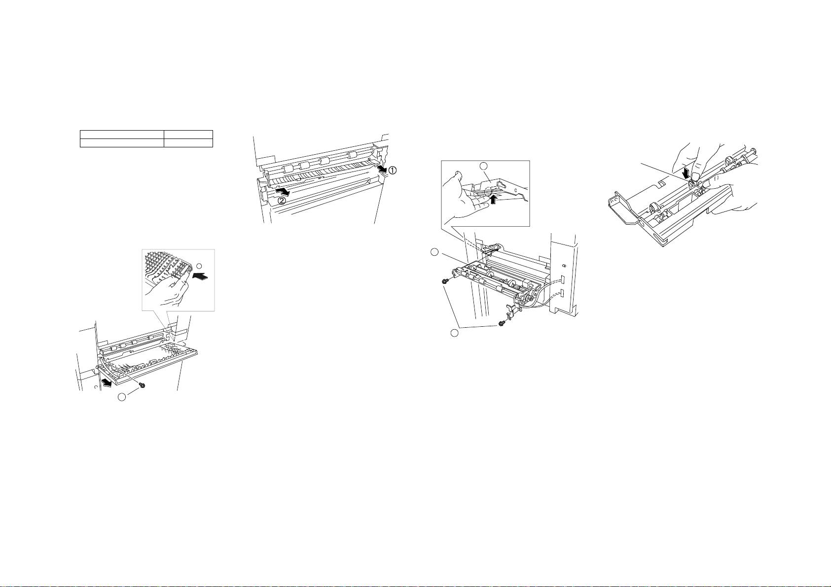
2.5.1 Feed Roller Replacement
2.5.3 No Paper Sensor Replacement
NOTE: • When replacing the Feed Roller, clear
the Feed Counter of the appr opri at e
Tray, using the Diag. Mode applicable:
Content Diag Mode
Tray 1 Feed Counter 30-1
Replacement Procedure Common
to the Above
Removal
1. WARNING: Power off the machine and
disconnect the power cord.
2. Slide out the appropriate Tray.
3. Remove the Transport Cover.
➀. Remove Screw.
➁. Push Transport Cover to rear side.
➂. Remove Transport Cover by sliding away
Pin on its front side.
2
4. (Fig. 2): Remove the Chute.
➀. Remove Chute from Pins by pulling its rear
side.
➁. Slide Chute to rear and remove it.
(Fig. 2)
5. (Fig. 3): Remove the Feeder Assy.
➀. Disconnect P/J610 (Tray 1) and the
Ground wire.
➁. Remove Screws (2). (Wire Guard
disengages together.)
➂. Lift No Paper Sensor Actuator manually.
➃. Remove Feeder Assy.
3
4
2
(Fig.4)
Replacement Procedure
for Feed Roller only
6. (Fig. 5): Remove the Feed Roller.
NOTE: • Do not contaminate the Roller surface
with grease, etc. Clean the
contaminated Roller surface with the
Drum Cleaner.
Feed Roller
(Fig. 5)
1
(Fig. 1)
Page 42

Replacement Procedure
For Pick Up Gear only
6. (Fig. 5): Remove the Pick Up Gear.
➀. Remove the Spring.
➁. Keep pushing the hook of the pick up gear
using the small screw gear.
➂. Remove the pick up gear.
Replacement Procedure
for No Paper Sensor only
6. (Fig. 6): Remove the No Paper Sensor.
➀. Remove No Paper Sensor tab.
➁. Lift Actuator.
➂. Remove No Paper Sensor.
➃. Remove Connector.
Common Procedure
Installation
1. Perform the installation in the reverse order of
removal.
NOTE: • (Fig.7): Install the Feeder Assy to the
machine with the Feed Roller halfmoon shaped facing upwards.
Face up
• (Fig. 8): Install the Feeder Assy to the
machine with the Assy cutouts hooked on
the machine pins.
Cut outs
➂
➀
(Fig. 5)
➁
(Fig. 8)
(Fig.6)
(Fig. 7)
• When installing the Feeder Assembly to
the machine, take great care not to
damage the No Paper Sensor Actuator.
• Reconfirm that the Feed Roller half-moon
shape faces upwards before installing the
appropriate Tray.
NOTE: • After the replacement of the No
Paper Sensor, check the Sensors
using the following Diag Codes.
Sensor Diag. C od e
Tray 1 No Paper Sensor 7-6
Pin
4-7 2. Paper Handling
Section 4 Disassembly/Assembly/Adjustment
Page 43

4-8
2.5.4 Transport Cover INTLK Switch
Replacement
Section 4 Disassembly/Assembly/Adjustment
4. Paper Handling
Removel
1. WARNING: Power off the machine and
disconnect the power cord.
2. Open the Transport Cover.
3. Remove the Transport Cover.
➀. Remove Screw.
➁. Push Transport Cover to rear side.
➂. Remove Transport Cover by sliding away
Pin on its front side.
1
(Fig. 1)
4. (Fig.2)Remove Transport Cover INTLK Switch.
➀. Push up the hook that fixes INTLK Switch.
➁. Slide out INTLK switch then disconne ct.
1
2
2
Installation:
1. Perform the installation in the reverse order of
removal.
(Fig.2)
Page 44

2.5.5 TRAY 1 Switch Replacement
2.5.6 TRAY 1 Switch Adjustment
Removal
1. WARNING: Power off the machine and
disconnect the power cord.
2Remove the Rear Lower Cover.
3Remover the LVPS
4(Fig1) Remove the Switch Bracket.
➀Remove screw.
Installation
1. Perform the installation in the reverse order of
the removal.
(Fig.1)
Purpose: To prevent the Tray from hitting
the Tray Switch, as deformation of
the Switch Actuator will lead to poor
contact.
1. WARNING: Power off the machi ne an d
disconnect the power cord.
2. Remove the Rear Lower Cover.
3. Remover the LVPS……………..………..9.1.3
4. (Fig.1)Loosen two fi xin g scre ws of Tray 1
Switch Bracket.
(Fig.1)
5. Tighten two fixing screws of Tray 1 Switch
Bracket.
4-9 2Paper Handling
Section 1 Service Procedure
Page 45

4-10
Section 4 Disassembly/Assembly/Adjustment
2. Paper Handling
2.7.1 Registration Assy
Removal/Installation
Removal
1. Power off the machine and disconnect the
Power Plug.
2. Remove the Drum Unit and place a black
bag over it ……………………………….. (5.1.1)
3. Remove the Deve. Unit. ………………. (6.2.1)
4. Remove the TC/DTC Assy.
5. Remove the following Covers:
• Right Upper Cover
• Rear Upper Cover
• Rear Lower Cover
6. Remove the MSI Feeder Assy. ……… (2.2.1)
7. (Fig. 1): Remove the Upper Chute Assy.
➀. Loosen Screw and remove Chute Bias
resistance.
➁. Remove Spring.
➂. Open Registration Assy pin-installed
bracket.
➃. Remove Upper Chute Assy.
8. (Fig. 2): Remove the Registration Assy.
➀. Disconnect P/J116 (for Regi-Sensor) &
P/J214 (for Regi-Gate Solenoid).
➁. Remove Screws(2).
➂. Remove Registration Assy.
1
2
3
(Fig. 2)
Installation
1. Reinstall the Registration Assy by reversing
Step 8, Removal.
2. Restore the machine to its original state in the
reverse order of the removal.
2.7.2 Registration Gate Solenoid
Replacement
2.7.3 Regi-Gate Sensor Replacement
• Replace both by removing the Registration
Assy....................………………………... (2.7.1)
• The Solenoid/Sensor can now be replaced.
2.7.4 Registration Roller Replacement
Removal
1. Power off the machine and disconnect the
Power Plug.
2. Remove the Registration Assembly ….. (2.7.1)
3. Remove the Registration Roller.
➀. (Fig.1): Remove E Clip and then Bearing.
(Fig. 1)
➁. (Fig.2): Remove Screw and then Gear.
(Fig. 2)
(Fig. 1)
Page 46

➂. (Fig. 3): Remove One-Way Clutch and
Gear. (Spring disengag es tog eth er. )
➃. Remove E Clip and then Bearing.
(Fig. 3)
➄. (Fig. 4): Turn over Registration Assy.
➅. Push in Registration Gate Solenoid plunger
with your finger.
➆. Remove Registration Roller (with plunger
pushed in).
(Fig. 4)
Installation
1. Perform the installation in the reverse order of
the removal.
2.7.6 Lead Edge Registration
Adjustment
Purpose To properly align the copy image on
the Drum with the lead edge of
paper.
Check
1. In 100% Mode, align Test Chart(4 99T 2 47 or
248) with Regi-Guide and make a copy.
2. (Fig. 1): Check that there is 10±1.6mm from
the copy’s lead edge to the reference line.
(Fig. 1)
Adjustment
• Fast Paper Feed(The distance is more than
10±1.6mm from the copy’s lead edge to the
reference line.)
1. Key in Diag. [20-1].
2. Increase data.
NOTE: • Changing the data by 1 will change the
distance by 0.2584mm.
• Slow Paper Feed(The distance is less than 10+
1.6mm from the copy’s lead edge to the
reference line.)
1. Key in Diag. [20-1].
2. Decrease data.
NOTE: • Changing the data by 1 will change the
distance by 0.2584mm.
3. Make a copy and check it.
4. Perform the ISIL Copy Edge Erase Amount
Adjustment ...................……………....... (5.1.6)
4-11 2. Paper Handling
Section 4 Disassembly/Assembly/Adjustment
Page 47

4-12
Section 4 Disassembly/Assembly/Adjustment
2. Paper Transport
3.1.1 Vacuum Transport Belt
Replacement
Removal
1. Power off the machine and disconnect the
Power Plug.
2. Open the Front Cover and then the machine.
3. Remove the Drum Unit and place a black
bag over it ……………………………... (5.1.1)
4. Remove the Rear Upper Cover.
5. Remove the TC/DTC Assembly.
6. (Fig. 1): Remove the Main Switch Cover.
➀. Remove Screw.
➁. Remove Main Switch Cover.
(Fig. 1)
7. (Fig. 2): Remove AC DRIVE PWB.
➀. Remove Screw.
➁. Remove AC Drive PWB Cover.
➂. Disconnect the plug and remove AC Drive
PWB,
3
ºóÃæ
2
1
(Fig. 2)
8. (Fig. 3): Remove the Vacuum Transport
Assembly.
➀. Remove Screw.
➁. Remove Vacuum Transport Assy.
NOTE: • Pushing the rear pin with a screw
driver as shown in Fig. 3 makes it
easier to remove.
(Fig. 3)
9. (Fig. 4): Remove the Transport Belt.
➀. Remove E Clip and then Bearing.
➁. Slide Shaft.
➂. Remove Transport Belt.
Installation
1. Perform the installation in the reverse order of
removal.
NOTE: • (Fig. 5): Pay attention to the Belt
direction.
(Fig. 5)
(Fig. 4)
Page 48

4.1.1 Platen Glass Replacement
Removal
1. Power off the machine and disconnect the
Power Plug.
2. Open the Platen Cover.
3. (Fig. 1): Remove the Platen Glass.
➀. Remove Screws (2).
➁. Remove Platen Glass Support.
➂. Remove Platen Glass.
4.1.2 Optical Cooling Fan Replacement
Removal
1. Power off the machine and disconnect the
Power Plug.
2. Remove the Left Upper/Rear Upper Covers.
3. (Fig. 1): Remove the Optical Cooling Fan.
➀. Disconnect P/J408.
➁. Remove Screws(2).
➂. Remove Optical Cooling Fan.
(Fig. 1)
Installation
1. Perform the installation in the reverse order of
removal.
Installation
1. Perform the installation in the reverse order of
removal.
Reference • This Fan cools the Optics by
taking air into the machine.
• Do not turn the Fan over when
installing it.
(Fig. 1)
4-13 4. Optics
Section 4 Disassembly/Assembly/Adjustment
Page 49

4-14
Section 4 Disassembly/Assembly/Adjustment
4. Optics
4.2.1 Optical Regi-Sensor Replacement
Removal
1. Power off the machine and disconnect the
Power Plug.
2. Remove the Platen Glass. ........…….... (4.1.1)
3. Open the Front Cover and remove the
Console Assy. ………………………... (10.2.1)
4. (Fig. 1): Loosen the Top Cover.
➀. Remove Front Screws(2) to enable Top
Cover Fron t to be raised.
(Fig. 1)
5. (Fig. 2): Remove Optical Regi-Sensor.
➀. Raise Top Cover a little.
➁. Remove Screw.
➂. Remove Regi-Sensor.
➃. Disconnect P/J100.
1
2
4
(Fig. 2)
Installation
1. Perform the installation in the reverse order of
removal.
NOTE: • While pushing the Regi-Sensor toward
the lower right to eliminate end play,
tighten the Screw.
3
4.2.2 Lamp Carriage Motor
Replacement
Removal
1. Power off the machine and disconnect the
Power Plug.
2. Remove Rear Upper Covers.
3. (Fig. 1): Remove Lamp Carriage Motor.
➀. Disconnect P/J605.
➁. Remove Screws(2).
➂. Remove the Motor.
(Fig. 1)
Installation
1. Perform the installation in the reverse order of
removal.
2. Make a copy of Test Chart(499T247 or 248)
and check that it exhibits no skip, that no
abnormal noises are heard, etc.
Page 50

4.2.3 Carriage Cable Replacement
NOTE: • The Cable winding procedur e is
described only for the Front Cable
because the Front and Rear Cables are
symmetrically wound.
• Prepare Scotch tape.
• Replace Cables one by one.
Refer to the location of the installed
wiring for the correct Cable routing.
Reference The Rear Cable is painted in black.
Removal
1. Power off the machine and disconnect the
Power Plug.
2. Remove the Platen Cover .
3. Remove the Platen Glass. ……………. (4.1.1)
4. Remove the Top Cover. ……………. . (10.2.2)
5. Remove the Regi-Guide.
6. (Fig. 1): Gently move the Full-Rate Carriage
manually up to the frame hole at the right of
the Regi-Sensor.
(Fig. 1)
7. (Fig. 2) : Loosen the Cable Mounting Screw for
the Full-Rate Carriag e.
NOTE: • When replacing the Rear Cable, remove
the Optical Cooling Fan. …….... (4.1 2)
(Fig. 2)
8. (Fig. 3): To make the rest of this procedure
easier, gently move the Full-Rate Carriage
up to the frame cutout.
NOTE: • Move the Carriage by holding at the
rear keeping it perpendicular to the
frame because its front is not fixed to
the Cable.
9. (Fig. 4): Remove the Cable from the spring
and then the whole Cable from the machine.
(Fig. 4)
Installation
1. (Figs. 5 & 6): Wind the Cable on the Capstan
Pulley.
➀. (Fig. 5): Determine the Cable direction.
➁. Wind Cable on Capstan Pulley shaft nine
turns.
NOTE: • The Full-Rate Carriage should be
positioned at the frame cutout in Fig.3.
➂. (Fig. 6): With the Cable-centering ball
in the Capstan Pulley hole, wind the
Cable five turns on the front side and
three turns on the rear side centering
on the ball. The total number of winds
is nine, including one wind at the
central ball. (Overlap of the cable
windings is allowed here.)
(Fig. 6)
(Fig. 3)
(Fig. 5)
4-15 4. Optics
Section 4 Disassembly/Assembly/Adjustment
Page 51

4-16
Section 4 Disassembly/Assembly/Adjustment
4. Optics
2. (Fig. 7): Route the ball-attached side of Cable
to the Pulley via the far left Pulley as shown in
Fig. 7, then fasten the ball into the left-hand
Frame hole.
(Fig. 7)
3. (Fig. 8): Route the ring-attached side of cable
to the Pulley via the Full-Rate Carriage and,
then hook the ring on the right-hand-Frame
spring.
4. (Fig. 9): Finger tighten the Cable Mounting
Screw for the Full-Rate Carriage.
(Fig. 9)
5. (Fig. 10): Arrange the cable windings on
the Capstan Pulley by holding the Full-Rate
Carriage with your hand and gently moving it
right and left.
4.3.1 Full-Rate & Half-Rate Carriages
Parallel Adjustment
Purpose To set the Carriages parallel so that
the Front/Rear Light Paths ar e the
same in length.
NOTE: • This adjustment should be performed
when the following problem occurs or
after the work is complete:
1. Optical Skew(Skewed image)
2. Carriage Cable Removal/Installation
(4.2.3)
Check
1. Power off the machine and disconnect the
Power Plug.
2. Remove the Platen Cover.
3. Remove the Platen Glass. ………….… (4.1.1)
4. Remove the Left Upper Cover.
5. Remove the Top Cover. …………….. (10.2.2)
6. Remove the Regi-Guide.
7. Remove the Blocks for Parallel Adjustment
from the Left-Hand Frame by moving the FullRate & Half-Rate Carriages manually to the
Right.
➀. (Fig. 1): Push Block A convex from the
frame hole and turn Block A through 180
degrees.
(Both front and rear).
(Fig. 1)
➁. (Fig. 2): Remove Block B’s and install them
to Full-Rate Carriage front/rear.
(Fig. 8)
(Fig. 10)
6. Perform the Full-Rate & Half-Rate Carriage
Parallel Adjustment. ...............……...... (4.3.1)
7. Reinstall all the parts and make a copy. Check
that the copy exhibits no optical skew, etc.
(Fig. 2)
Page 52

8. (Fig. 3): Move gently the Full/Half-Rate
Carriages toward their hom e posi ti ons by
rotating the Capstan Pulley shaft manually to
check the following:
• The Half-Rate Carriage convex contacts
Block A’s at its front and rear.
• Block B’s installed to the Full-Rate Carriage
contact the Left-Hand Frame at its front and
rear.
Adjustment
Half-Rate Carriage Adjustmen t
1. (Fig. 4): Make the Half-Rate Carriage convex
contact (Front/Rear) Block A’s.
➀. Loosen screws(2) for Front Capstan Pulley.
➁. Adjust by rotating Capstan Pulley or Shaft.
NOTE: • Do not remove Screw for Rear
➂. Tighten Screws(2).
Reference The standard tightening Torque is
Capstan Pulley.
0.5N
•m(5kgf•cm).
2. (Fig. 5): Remove the end play in the Drive
Shaft axis direction and tighten the screws for
the Capstan Pulley.
➀. Insert 0.5mm Thickness Gauge between
Capstan Pulley and Bearing.
➁. Push Capstan Pulley to front and Shaft to
rear and tighten screws(2).
Full-Rate Carriage Adjustment
1. (Fig. 6): Make (Front/Rear) Block B’s installed
to the Carriage contact the Left-Hand
Frame.
➀. Loosen the Carriage Wire Mounting Screw.
NOTE: • For the adjustment of Rear Block B,
remove the Optical Cooling Fan.
.........………………………….. (4.1.2)
➁. Adjust by moving the Carriage.
➂. Tighten Screw.
(Fig. 4)
(Fig. 3)
(Fig. 5)
(Fig. 6)
4-17 4. Optics
Section 4 Disassembly/Assembly/Adjustment
Page 53

4-18
Section 4 Disassembly/Assembly/Adjustment
4. Optics
4.3.2 Exposure Lamp Replacement
NOTE: • Do not touch the Exposure Lamp glass
tube with your hand. If you touch it,
wipe it with the Drum Cleaner.
• Take care not to hit the Exposure Lamp
glass tube. It is fragile.
Removal
1. Power off the machine and disconnect the
Power Plug.
2. Open the Platen Cover.
3. Remove the Platen Glass. .......……..... (4.1.1)
4. (Fig. 1): Move the Full-Rate Carriage gently
to the frame cutout and remove the Lamp.
➀. Remove Screw.
➁. Remove Front/Rear Side Reflectors.
➂. Remove Cover.
➃. Push open Front Contact Plate with your
fingers.
➄. Remove Lamp .
Installation
1. Perform the installation in the reverse order of
removal.
NOTE: • (Fig. 2): Install the Lamp with its
protrusion facing the Reflector
opening approx. 45° from the Platen
Glass surface .
(Fig. 2)
2. Key in Diag. Mode [6-7] and check that the
Lamp is on.
3. Perform the Basic Copy Quality Adjustment.
…………………………………………….. (5.1. 4)
4.3.3 Optical Skew Adjustment
Purpose To correct the optical image skew in
the Drum axis and paper feed
directions.
NOTE: • Ensure that the following are
functioning correctly:
1. Paper is fed properly.
a. There is no difference in skew level between
Trays.
b. There is no difference in skew level between
continuously-made copies.
2. The Regi-Guide(or Gate) and the Platen Glass
are positioned properly.
3. The Full-Rate/Half-Rate Carriages Parallel
Adjustment is properly performed. …...
(4.3.1)
4. There is no difference in skew level between
A4 & A3 ( or between B5 & B4).
* If there is some difference, check to see if
the bottom half of A3(or B4) paper skews due
to the uneven transporting force of the Fuser
owing to a defective P Roll. Replace the P
Roll if necessary.
* The Regi-Roll is deteriorated or worn out.
5. Do not ad just paper skew by this means.
6. After this adjustment, make sure to record in
the Machine History Card that it has been
performed.
Adjustment Flow chart
(Fig. 1)
Page 54

Check
1. Align Test Chart(499T24 7) wit h th e RegiGuide and make a size- for-size copy of it on
A3 paper.
2. (Fig. 1): Measure A, B, C & D each. Check
that the values each obtained by subtracting B
from A and D from C are in the specifications
below:
A – B → within ± 1.6mm
C – D → within ± 2.0mm
(Fig. 1)
Adjustment
A - B is out of spec.
1. Power off the machine and disconnect the
Power Plug.
2. Remove the Platen Glass. .........……... (4.1.1)
3. Remove the Optical Cooling Fan. ...….. (4.1.2 )
4. (Fig. 2): Move the Full-Rate Carriage holding it
at its rear.
NOTE: • Do not move the Carriage right and left
more than 2mm; otherwise, there could
occur problems such as poor resolution
and the Carriage slamming on the
frame.
➀. Remove Carriage Wire Mounting
Screw.
➁. Adjust by moving Full-Rate Carriage
with Carriage Cable still.
• A>B
Move the Carriage to
the right.
• A<B
Move the Carriage to
the left.
➂.Tighten Screw.
C - D is out of spec.
1. Power off the machine and disconnect the
Power Plug.
2. Remove the Platen Glass. ………….…. (4.1.1)
3. Remove the Right Upper Cover.
4. (Fig. 3): Move the Half-Rate Carriage holding it
at its front.
NOTE: • Do not move the Carriage right and left
Reference The standard tightening torque is
more than 2mm; otherwise, there could
occur problems such as poor resolution
and the Carriage slamming on the
frame.
➀. Loosen Front Capstan Pulley
screws(2).
➁. (Fig. 3): To adjust, move the Half-
Rate Carriage by rotating the
Capstan Pulley.
NOTE: • Do not remove the screw for
➂. Tighten Screw.
the Rear Capstan Pulley.
• Do not rotate the Carriage
Drive Shaft.
• In the case of C > D, rotate the
Capstan in the −
• In the case of C < D, rotate the
Capstan in the −
0.5N
• m(5kgf • cm).
a direction.
b direction.
4.3.4 Size-for-Size Fine Tuning
Purpose To set the vertical magnification
(Scan direction) and horizontal
magnification(Drum axis direction).
Reference When the machine is shipped out
from the plant , its copy ma gn if icat io n
is set to 100% ± 0.8%.
Check
1. Make a size-for-size A3 copy of Test Chart
(499T247).
2. (Fig. 1): Check that designated locations are
the same in length by comparing Test Chart
with the copy as follows:
• Vertical Magnification
Check on ➁ to ➃, ➁ to ➄ and ➃ to ➄.
• Horizontal Magnification
Check on ➀ to ➁, ➁ to ➂ and ➀to ➂.
(Fig. 1)
(Fig. 3)
(Fig. 2)
4-19 4. Optics
Section 4 Disassembly/Assembly/Adjustment
Page 55

4-20
Section 4 Disassembly/Assembly/Adjustment
4. Optics
Adjustment
• Vertical Magnification
Change the vertical magnification (Scan
direction) referring to Table 1.
• Horizontal Magnification
Change the horizontal magnification (Drum
axis direction) referring to Table 1.
0
(-2%)
0
(-3%)
Initial
Value
32
(±0%)
32
(±0%)
Chain Code Content Min.
20
100%
Horizontal Mag.
6
Fine Tuning
100% Vertical
7
Mag. Fine
Tuning
Max.
64
(+2%)
64
(+3%)
4.5.3 Lens Cable Replacement
Removal
1. Select 100% Magnification. After the Lens
stops, power off the machine and disconnect
the Power Plug.
2. Open the Platen Cover and remove the
Platen Glass. ……………………………
(4.1.1)
3. (Fig. 1): Remove the Optical Shield.
➀. Loosen Screws(2)
➁. Raise the rear side of Mirror Carriage and
remove Optical Shield.
(Fig. 1)
4. (Fig. 2): Remove the Lens Carriage Shield.
➀. Remove Screw.
➁. Remove Lens Carriage Shield.
NOTE: • Take care not to break the film
5. Check the following:
• (Fig. 3): The Lens Carriage timing hole
should align with the Rail timing hole.
(Fig. 3)
6. (Fig. 4): Remove the Lens Cable.
• First unhook the spring-attached side of
Cable.
attached to the Shield.
(Fig. 2)
(Fig. 4)
Page 56

Installation
1. (Fig. 5): Check that the Lens Carriage timing
hole aligns with the Rail timing hole. Tape the
Lens Carriage to the frame.
(Fig. 5)
2. Hook the shorter side of Cable from its ball on
the Lens Carriage.
NOTE: • (Fig. 5): Hook the Cable with the flat
side of the hook toward the Carriage .
3. (Fig. 6): Route the Cable to shaft of Pulley
then to the Pulley
Gear Pulley. Wind the Cable five turns in total,
inserting the ball into the Gear
inserting the ball into the Gear
Pulley hole.
B
, and finally wind it on the
(Fig. 6)
A
,
4. (Fig. 7): Route the longer side of Cable form
its ball to the Pulley, then hook it on the Lens
Carriage with the spring.
(Fig. 7)
5. Remove the tape fixing the Lens Carriage and
route the Cable to the Pulley
6. Power on the machine. Check that the Lens
Carriage timing hole aligns with the Rail timing
hole(Step 5, Removal) when the Lens is set to
100%. If the holes don’t align with eac h other,
check the installation procedure again. Check,
in particular, that the Cable ball is in the Gear
Pulley hole.
7. Select 61%/163% Magnifications respectively.
Check the following:
• The Lens Carriage moves smoothly.
• The Cable windings on the Gear Pulley are
not overlapped.
8. Restore the machine to its original state. Make
copies using Enlargement/100%/Reduction
Modes respectively. Check that the copies are
good. Perform the Size-for-Size Fine Tuning
(4.3.4) if necessary.
A
.
4-21 4. Optics
Section 4 Disassembly/Assembly/Adjustment
Page 57

4-22
Section 4 Disassembly/Assembly/Adjustment
4. Optics
4.5.4 Lens Motor Replacement
Removal
1. Select 100%. After the Lens stops, power off
the machine and disconnect the Power Plug.
2. Remove the Right/Rear Upper Covers.
3. Open the Front Cover, and then the machine.
4. Remove the Drum Unit and place a black
bag over it. ………………………….. (5.1.1)
5. Remove the Deve. Unit. ...........….….. (6.2.1)
6. Close the machine.
7. Remove the Platen Glass. …………… (4.1.1)
8. (Fig. 1): Remove the Optical Shield.
➀. Loosen Screws(2).
➁. Raise the rear side of Mirror Carriage and
remove Optical Shield.
(Fig. 1)
9. (Fig. 2): Disconnect Connector P/J604 from
the Lens Motor.
(Fig. 2)
10. Remove the Motor wire from each Cable
clamp.
11. (Fig. 3): To fix the Mirror Carriage positi on
at 100%, insert the Phillips Screwdriver
through the Worm Wheel timing hole to the
frame timing hole. (The scre wdri v er goe s
through the frame hole.)
12. (Fig. 4): Remove the Gear.
➀. Remove E Clip.
➁. Remove Gear.
(Fig. 4)
13. (Fig. 5): Remove the Lens Mot or.
➀. Remove Screws (2).
➁. Remove Lens Motor.
Installation
1. Perform the installation in the reverse order of
removal. Pay attention to the following:
NOTE: • (Fig. 6): When installing the Lens
Motor, check that the Lens Carriage
is set to 100%.
(Fig. 6)
2. Make copies using 100%, 70% and 141%
Magnifications respectively. Check that the
copies are good.
(Fig. 3)
(Fig. 5)
Page 58

5.1.1 Drum Unit Replacement
NOTE: • Be careful of the following in handling
the Drum Unit:
a. Place the removed Unit on a flat
surface.
b. Keep the Drum away from direct
strong light. Put a protective cover
over it.
c. Do not rotate the Drum anti --
clockwise.
e. Do not touch the Drum surface with
your bare hand(s).
Removal
1. Power off the machine and disconnect the
Power Plug.
2. Open the Front Cover and then the machine.
3. (Fig. 3): Remove the Drum Unit.
➀. Push Lock Lever.
➁. Pull out Drum Unit.
(Fig. 1)
Installation
1. Install the Drum Unit securely. Its improper
installation will cause J3 to be displayed.
Put the plug ID into the socket.
2. Perform the Basic Copy Quality Adjustment.
…………………………………………….. (5.1. 4)
Reference •••• Drum Unit
a. When replacing the Drum,
replace the whole Drum Unit.
(It is impossible to replace the
Drum alone.) The Drum Unit
contains the Drum Cleaning
Blade, Film Seal and Charge
Corotron.
b. Max. Copy Output Quantity
When the Drum Unit is shipped
out of the plant, the max. copy
output quantity is set on
ID as below:
Max. Copy Output
M/C
Type
Qty on ID
(Initial Value)
5915 50,000
c. “Drum Cartridge(Unit)
Replacement” Display
Remaining
Copy
Output Qty
5,000 ON -- Possible
500 Flash -- Possible
0
Drum
Cartridge
Replacement
Display
Flash
(continuously)
Status
Code
J7-1
When the cartridge reaches
the end of its service life, the
Replace copy cartridge lamp
flashes and the Copy Quantity
display shows “J7”.
d. Remaining Copy Output Qty
The remaining copy output
quantity is stored in EPROM
incorporated into the Drum
Unit. You can check on the
remaining copy output quanti ty
in [81] of “Performance Spec.”
Copy
Not
possible
5.1.2 Drum Finger Replacement
Removal
1. Power off the machine and disconnect the
Power Plug.
2. Open the Front Cover and then the machine.
3. Remove the Drum Unit......………......... (5.1.1)
4. (Figs. 1 & 2): Remove the Finger Assembly.
➀. (Fig. 1): Remove Stopper preventing the
disengagement of Finger Assy.
(Fig. 1)
➁. (Fig. 2): Remove Finger Assy from Bracket
by sliding it to the front of Drum Unit.
(Fig. 2)
5. (Fig. 3): Remove the Drum Finger.
WARNING: • Take care not to hurt yourself in
removing the Finger. Its tip is
sharp.
➀. Remove Spring.
➁. Remove Drum Finger.
(Fig. 3)
Installation
1. Perform the installation in the reverse order of
removal.
CAUTION: • Check that the Drum Finger tip is
not damaged.
• Take care not to damage the Drum
surface in installing the Finger
Assy.
• Install the Stopper in the proper
direction referring to Fig. 1.
4-23 5. Xerographic
Section 4 Disassembly/Assembly/Adjustment
Page 59

4-24
Section 4 Disassembly/Assembly/Adjustment
5. Xerographic
5.1.3 Charge Corotron Wire Replacement
Removal
1. Power off the machine and disconnect the
Power Plug.
2. Open the Front Cover and then the machine.
3. Remove the Drum Unit. ……................
(5.1.1)
4. (Fig. 1): Remove the Charge Corotron
Assembly.
➀. Remove Screw.
➁. Remove Charge Corotron Assy.
(Fig. 1)
5. (Fig. 2): Remove the Charge Corotron Wire.
➀. Remove Front/Rear Arc Shields.
➁. Remove Spring.
➂. Remove Corotron Wire.
(Fig. 2)
Installation
1. Perform the installation in the reverse order of
removal.
NOTE: • The copy edge erase amount changes
according to the Front Arc Shield
installing position. Install the Arc Shield
so that the copy edge erase amount
after replacement is the same as
before.
5.1.4 Basic Copy Quality Adjustment
Purpose To determine the correction values
of Exposure Light Quantity and
Deve. Bias to obtain copy densities
appropriate to various t ypes of
original.
NOTE: • Copy Quality Adjustment should
be performed when copy qual it y
problems occur or the following are
replaced:
➀. Drum Unit Replacement ....... (5.1.1)
➁. Exposure Lamp Replacement
……………………………….. (4.3.2)
➂. Main PWB Replacement ...... (9.1.2)
NOTE: • Perform TRIM before making the Copy
Quality Adjustment.
Adjustment Fl ow
5.1.4-A Exposure Light Quantity Setup
Purpose To adjust light quantities applicable
Check
1. Enter Diag. Mode [20-2].
The Control Panel displays the following:
2. Check that the magnification is 100%.
3. Set Test Chart(499T247 or 499T248) and
select A3 or B4.
4. Press the Start button and make three straight
copies. (Press the Stop button when the third
copy has been made.)
NOTE: • Because pressing the Start button in
5. Evaluate the third copy.
Spec: At the target in the center of the copy.
to each magnification and store the
values in NVM.
Set/Count 30
Diag. [20-2] will allow ten straight
copies to be made, press the Stop
button at the completion of the third
copy.
• This Diag Mode detects paper jams
and counts.
• (Fig. 1): 0.1 gray vertical/horizontal
lines disappear.
• 0.2 gray vertical/horizontal lines are
reproduced.
(Fig. 1)
Page 60

6. Go to one of the following steps per the result
of the evaluation.
Within Spec. → Perform Steps 3 through 5 in
70%/141% magnification
modes.
Out of Spec. → Proceed with the adjustment
procedure.
Adjustment
Reference
NOTE: • Make sure to first perform the
Adjustment Fl ow
The Exposure Light Quantity can
be set up by changing the NVM
value.
a. Normally adjust by the [20-2]
value.
b. Adjust by [20-20] in the cases
below:
• Light Quantity is unadjustable
by the NVM value.
• The Main PWB has been
replaced.
adjustment in 100% mode.
Adjustment by NVM Value (Normal Adjustment)
1. Enter Diag. Mode [20-2].
2. Select 100% Magnification .
3. The exposure setting is adjusted by pressing
the following buttons on the keyboard:
. a. Button 6 to decrease the Exposure.
b. Button 9 to increase the Exposure.
4. While making the copies, adjust the exposure
so that the .20 gray lines are reproduced
clearly and the .10. gray lines disappear.
5. When the correct setting has been achieved,
press the Start button and make three straight
copies.
6. Repeat Steps 3,4 & 5 until the results satisfy
the spec. in Step 5, Check.
7. When the reproduced copies meet the spec,
press the Start button while the machine is
running in Diag. Mode[20-2]. This enables the
light quantity to be stored in NVM.
8. Perform Steps 3 through 7 in 70%/141%
modes.
Adjustment by [20- 20]
1. Enter Diag. Mode [20-20].
The Control Panel displays the following:
Set/ Count 50
2. Select 100% Magnification
3. Using the ke ybo ar d, ent er num b er:
Increasing the number increases the exposure
Decreasing the number decreases the
exposure.
4. Check the copy meets the spec in step 5 of
“check” .
5. Perform steps 3 to 7 of Adjustment by NVM
[20-2] Value Process Normal Value.
4-25 5. Xerographic
Section 4 Disassembly/Assembly/Adjustment
Page 61

4-26
Section 4 Disassembly/Assembly/Adjustment
5. Xerographic
5.1.5 ISIL Assembly Replacement
Removal
1. WARNING: Power off the machine and
disconnect the power cord.
2. Open the Front Cover and then the machine.
3. Remove the Drum Unit and place a black
bag over it. ……………………………. (5.1.1)
4. Remove the Deve. Unit. .........……….... (6.2.1)
5. (Fig. 1): Remove the ISIL Assembly.
➀. Remove P/J200.
➁. Remove Screw.
NOTE: • Do not lose Spring.
➂. Remove ISIL.
(Fig. 1)
Installation
1. Perform the installation in the reverse order of
removal.
2. Perform the Rear Side Edge Erase Amount
Check of the ISIL Copy Edge Erase Amount
Adjustment. …………………………….. (5.1.6)
5.1.6 ISIL Copy Edge Erase Amount
Adjustment
NOTE: • Ensure that the following adjustment is
properly performed before making this
adjustment:
Lead Edge Registration Adjustment
……………………………………. (2.7.6)
Check
1. Make three size-for- size copies of Test
Chart(499T247) onto A3. Check the third copy.
2. (Fig. 1): Check the erase amount.
• 4mm along lead/trail edges
• 4mm or less at rear
NOTE: • Front Side Edge Amount is set up by
moving the Front Shield Cover of the
Charge Corotron.
(Fig. 1)
Adjustment
Lead Edge
1. Enter Diag. Mode and key in [20-4].
2. The current set value appears.
3. Key in a new set value and press the Start
button.
Increase the value. → The erase amount
Decrease the value. → The erase amount
• The adjustable range in the Diag. Mode is
0~64.
• A step of “1” will change the erase amount
by 0.2584mm.
• The initial value is 32.
Trail Edge
1. Enter Diag. Mode and key in [20-5].
2. The current set value appears.
3. Key in a new set value and press the Start
button.
Increase the value. → The erase amount
Decrease the value. → The erase amount
• The adjustable range in the Diag. Mode is
0~64.
• A step of “1” will change the erase amount
by 0.2584mm.
• The initial value is 32.
Rear Side
1. Open the Front Cover.
2. (Fig. 2): Perform the ISIL Positioning
Adjustment.
A
. The erase amount decreases.
B
. The erase amount increases.
decreases.
increases.
decreases.
increases.
(Fig. 2)
Page 62
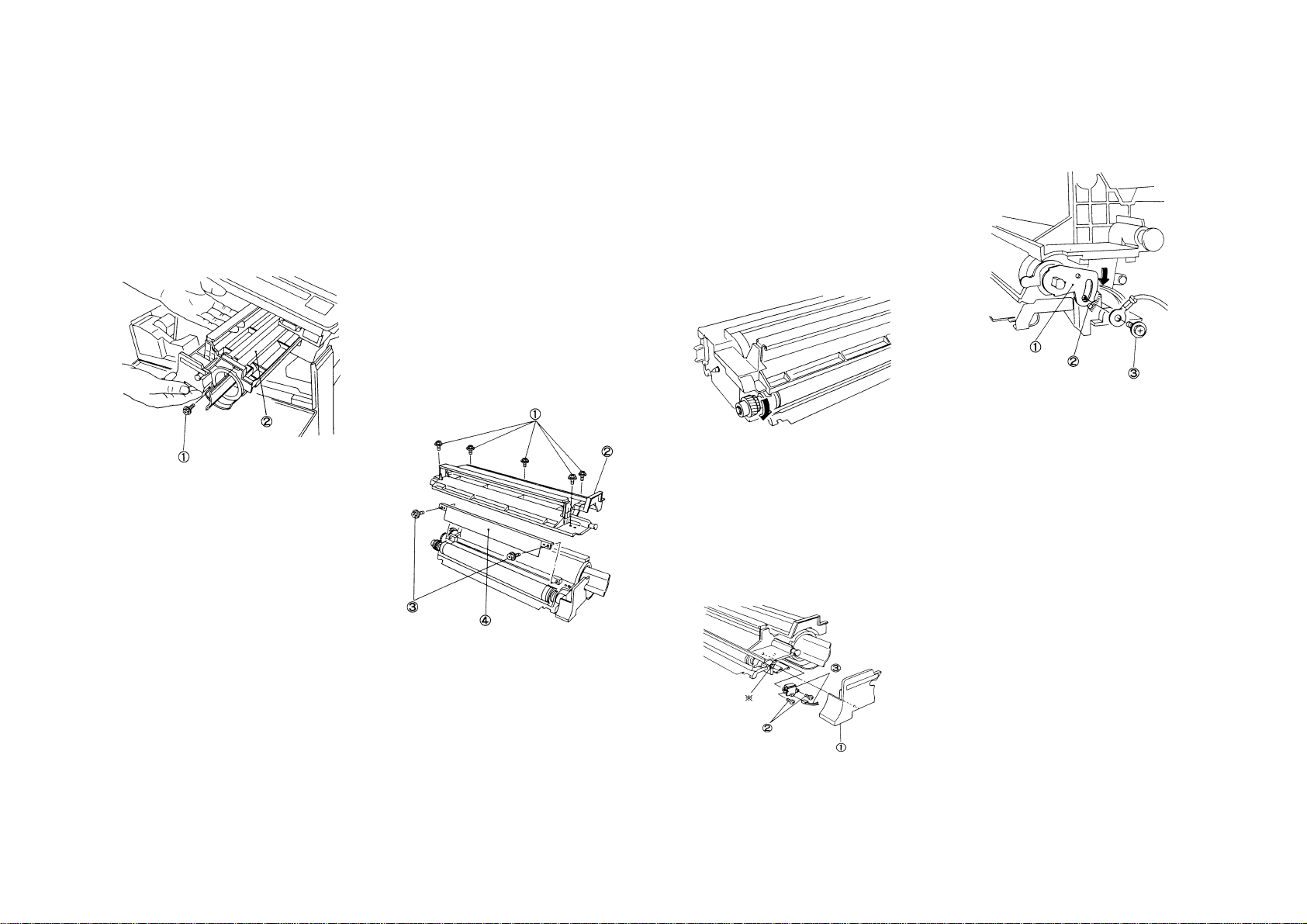
6.2.1 Deve. Unit Removal/Installation
Removal
1. WARNING: Power off the machine and
disconnect the power cord.
2. Open the Front Cover and then the machine.
3. (Fig. 1): Remove the Deve. Unit.
NOTE: • Ensure before the work that the Deve.
Unit separates fully from the Drum .
When you open the machine, the Deve.
Unit will separate from the Drum.
➀. Remove Screw.
➁. Remove Deve. Unit.
(Fig. 1)
Installation
1. Perform the installation in the reverse order of
removal.
6.2.2 Mag. Roll Blade Replacement
6.2.3 Toner Empty Sensor Replacement
Common Procedure
Removal
1. WARNING: Power off the machi ne an d
disconnect the power cord.
2. Open the Front Cover and then the machine.
3. (Fig. 1): Remove the Deve. Unit. …...... (6.2.1)
Replacement Procedure Exclusively
For Mag. Roll Blade
4. (Fig. 1): Remove the Deve. Housing Upper
Cover and then the Mag. Roll Blade.
NOTE: • Do not rotate the Mag. Roll after
removing the Mag. Roll Blade,
otherwise; a large quantity of toner
will be spilled.
➀. Remove Screws (5).
➁. Remove Upper Cover.
➂. Remove Screws(2).
➃. Remove Mag. Roll Blade.
Installation
1. Perform the installation in the reverse order of
removal. Pay attention to the following:
NOTE: • Ensure that the Blade and the Mag.
Roll have no foreign objects on thei r
surfaces.
• Install the Blade flat.
• (Fig.2): After the assembly, ensure that
there are no white streaks, etc. in the
Mag. Roll rotating direction, by turning
the Mag. Roll Gear in the direction of
arrow. If any white streaks, etc.
exist, find their cause such as mixed
foreign objects and remove them.
(Fig. 2)
Replacement Pr oce d ur e for To ner Empty
Sensor only
4. (Fig. 3): Remove the Toner Empty Sensor.
NOTE: • Take care not to cause any pressure or
shock to the detection surface of the
Empty Sensor.
➀. Remove Deve. Housing Front Cover.
➁. Remove Screws (2).
➂. Remove Toner Empty Sensor, then
disconnect P/J122.
NOTE: • When loosening or removing the
Installation
1. Perform the installation in the reverse order of
Screw wi t h ✴, put the MSA Plate ➀
against the protrusion ↑ and tighten
the screw ➂ as shown in Fig. 4.
(Fig. 4)
removal.
(Fig. 1)
(Fig. 3)
4-27 6. Development
Section 4 Disassembly/Assembly/Adjustment
Page 63

4-28
Section 4 Disassembly/Assembly/Adjustment
8. Fuser
8.1.1 Fuser Thermostat Replacement
8.1.2 Fuser Thermistor Replacement
Common Procedure
Removal
1. WARNING: Power off the machine and
disconnect the power cord.
WARNING
Fuser surfaces are hot, allow the fuser to cool
down before attempting service procedure.
Fuser lubricant can cause discomfort to eyes.
Do not allow fuser lubricant to touch eyes.
2. Open the Front Cover and then the machine:
3. Remove the Drum Unit and place a black
cover over it. …………………………….. (5.1.1)
4. Remove the Left Upper Cover.
5. (Fig. 1): Remove the Main Switch Cover.
➀. Remove Screw.
➁. Remove Main Switch Cover.
6. (Fig. 2): Remove the Fuser Cover.
➀. Loosen Screw.
➁. Remove Fuser Cover.
(Fig. 2)
Replacement Pr oce d ur e for Th er m os ta t only
7. (Fig. 3): Remove the Thermostat.
➀. Remove Wire going to Thermostat.
➁. Loosen Screws (2) and remove Sensor
Bracket.
➂. Remove Thermostat.
(Fig. 3)
Replacement Pr oce d ur e for Th er m ist or only
7. (Fig. 4): Remove the Thermistor.
➀. Disconnect P/J118.
➁. Remove Screw and then Thermistor.
(Fig. 4)
Common Procedure
Installation
1. Perform the installation in the reverse order of
removal.
(Fig. 1)
Page 64

8.2.1 Heater Rod Replacement
NOTE: a. Take great care in handling the Heater
Rod glass tube. It is fragile.
b. Do not touch the Heater Rod glass
tube with your bare hand(s). If you
touch it, wipe it with Drum Cleaner.
Removal
1. WARNING: Power off the machine and
disconnect the power cord.
WARNING
Fuser surfaces can be hot. Fuser lubricant can
cause discomfort to eyes. Do not allow fuser
lubricant to touch eyes.
2. Open the Front Cover and then the machine.
3. Remove the Drum Unit and place a black
bag over it. …………………………….. (5.1.1)
4. Remove the Left/Rear Upper Covers.
5. (Fig. 1): Remove the Main Switch Cover.
➀. Remove Screw.
➁. Remove Main Switch Cover.
6. Disconnect P/J’s 12, & 13 from the Heater
Rod.
7. (Fig. 2): Remove the Front/Rear Heater Rod
Covers each.
➀. Loosen Screw.
➁. Remove Front/Rear Heater Rod Covers.
(Fig. 2)
8. (Fig. 3): Remove the Heater Rod.
➀. Loosen Screw.
➁. Remove Front Support Bracket.
➂. Remove Heater Rod.
NOTE: • Hold the in su la to r an d ta ke out the
Heater Rod.
(Fig. 3)
Installation
1. Perform the installation in the reverse order of
removal.
NOTE: • Determine which way(front or re ar ) the
Heater faces by the color of the
connector.
(Fig. 1)
4-29 8. Fuser
Section 4 Disassembly/Assembly/Adjustment
Page 65

4-30
Section 4 Disassembly/Assembly/Adjustment
8. Fuser
8.2.2 Heat Roller Replacement
Removal
1. WARNING: Power off the machine and
disconnect the power cord.
WARNING
Fuser surfaces are hot, allow the fuser to cool
down before attempting service procedure.
Fuser lubricant can cause discomfort to eyes.
Do not allow fuser lubricant to touch eyes.
2. Open the Front Cover and then the machine.
3. Remove the Drum Unit and place a black
bag over it. ……………………………. (5.1.1)
4. Remove the Left/Rear Upper Covers.
5. (Fig. 1): Remove the Main Switch Cover.
➀. Remove Screw.
➁. Remove Main Switch Cover.
(Fig. 1)
6. (Fig. 2): Disconnect P/J117 (for Fuser Exit
Switch) at rear. Remove the Fus er Cove r an d
the Finger Assy.
➀. Disconnect P/J117.
➁. Loosen Screw and Remove Fuser Cover.
➂. Loosen Screw and Remove Finger Assy.
(Fig. 2)
7. (Fig. 3): Remove the Sensor Bracket.
➀. Loosen Screws (2).
➁. Remove Sensor Bracket.
(Fig. 3)
8. Remove the Heater Rod. …….............. (8.2.1)
9.(Fig. 4): Remove the Heat Roller.
➀. Remove Front/Rear Heat Roller Rings
➁. Remove Web Washer.
➂. Remove Heat Roller Collar.
➃. Remove Bearing.
➄. Remove Heat Roller. (Rear Gear will also
be disengaged.)
(Fig. 4)
Installation
1. Perform the installation in the reverse order of
removal.
Page 66

8.2.3 Pressure Roller Replacement
Removal
1. WARNIN: Power off the machine and
disconnect the power cord.
WARNING
Fuser surfaces are hot, allow the fuser to cool
down before attempting service procedure.
Fuser lubricant can cause discomfort to eyes.
Do not allow fuser lubricant to touch eyes.
2. Open the Front Cover and then the machine.
3. Remove the Heat
Roller………………….(8.2.2)
4. (Fig.1):Remove the Pressure Roller Finger
Assy.
➀. Remove Screw (2).
➁. Remove the Pressure Roller Finger Assy.
➀
(Fig. 1)
5. (Fig.2):Remove the Pressure Roller.
➀. Remove the Pressure Roller Finger Assy.
➁
➀
(Fig.2)
4-31 8. Fuser
Section 4 Disassembly/Assembly/Adjustment
Page 67

4-32
Section 4 Disassembly/Assembly/Adjustment
8. Fuser
8.2.4 Contact Arc Adjustment
Purpose To obtain the appropriate fusing
NOTE: A narrow contact arc would cause
Check
1. (Fig 1): Make two or three copies of A4(LEF)
paper with their halves solid bl ack .
Regard the copies as the measurement paper.
level.
improper fusing. Wide contact
arc or a great difference in contact arc
between front and rear would cause
wrinkled or curled copies.
A4
(Fig. 1)
2. Make fifteen copies of Test Chart onto A3
paper to even the temperatur es of the Hea t
Roller and the Pressure Roller.
3. Put the black copy obtained from procedure
No.1 on the MSI face down
4. Hold the measurement paper so that it copy
reaches the Heat Roll & the Pressure Roll.
5. Take out the measurement paper after closing
the machine for approx. 8~10 seconds
6. (Fig. 2): Open the measurement paper gently.
Take measurements at the positions 75 mm
from the both sides of the paper respectively
(at two positions on the fold made when the
paper is folded into quarters with its lead edge
aligning to its trail edge.)
•••• Proper width of NIP
5.5±0.15mm
75mm 75mm
NIP
297mm
measurement paper A4LEF
(Fig. 2)
Adjustment
1. (Fig. 3): Adjust by rotating the Adjustment
Screws(at front/rear).
➀. Loosen Lock Nut.
➁. Slide the bracket.
➂. Tighten Lock Nut.
NOTE: Width of NIP increases: Slide the bracket
to inside.
Width of NIP decreases: Slide the bracket
to inside.
decrease increas e
2. Adjust by repeating Check Steps 1 through 6.
Increase decrease
(Fig. 3)
Page 68

8.3.1 Heat Roller Fingers Replacement
8.3.2 Pressure Roller Fingers
Replacement
Common Procedure
Removal
1. WARNING: Power off the machine and
disconnect the power cord.
WARNING
Fuser surfaces are hot, allow the fuser to cool
down before attempting service procedure.
Fuser lubricant can cause discomfort to eyes.
Do not allow fuser lubricant to touch eyes.
2. Open the Front Cover and then the machine.
3. (Fig. 1): Remove the Main Switch Cover.
➀. Remove Screw.
➁. Remove Main Switch Cover.
Installation
1. Perform the installation in the reverse order of
removal.
NOTE: • (Fig. 4): When installing the Shaft to
the Finger Assy, pay attention to the
following:
➀. the position of the Exit Sensor
actuator.
➁. The longer hook of the spring
should be installed to the Finger
Assy.
Replacement Procedure for Pressur e Roller
Fingers only
5. (Fig. 5): Remove the Heat Roller Fingers.
➀. Remove Screws (2).
➁. Remove Pressure Roller Finger Assy.
(Fig. 5)
(Fig. 6)
(Fig. 1)
4. (Fig. 2): Disconnect P/J117(for Fuser Exit
Switch) at rear and remove the Fuser Cover
and the Finger Assy.
➀. Disconnect P/J117.
➁. Loosen Screw and remove Fuser Cover.
➂. Loosen Screw and remove Finger Assy.
(Fig. 2)
Replacement Procedure for Heat Roller
Fingers onl y
5. (Fig. 3): Remove the Heat Roller Fingers.
➀. Remove Screws(4).
➁. Remove KL Clips(2).
➂. Remove Heat Roller Fingers along with
their shafts.
(Fig. 3)
(Fig. 4)
6. (Fig. 6): Remove the Pressure Roller Fingers.
➀. Unhook the spring end.
➁. Pull out the Shaft
➂. Remove the Finger.
4-33 8. Fuser
Section 4 Disassembly/Assembly/Adjustment
Page 69

4-34
Section 4 Disassembly/Assembly/Adjustment
8. Fuser
Installation
1. Perform the installation in the reverse order of
removal.
NOTE: • (Fig. 7): Install the Finger with the both
ends of the Spring under the Shaft.
(Fig. 7)
8.5.1 Fuser Fan Motor Assembly
Replacement
Removal
1. WARNING: Power off the machine and
disconnect the power cord.
2. Remove the Platen Glass. ……............ (4.1.1)
3. Open the Front Cover and then the machine.
4. Remove the Left/Rear Upper Covers.
5. Remove the Drum Unit and place a black
bag over it. ……..,………………………. (5.1.1)
6. Move the Full-Rate Carriage slowly to the
right.
7. (Fig. 1): Loosen the Fuser Fan Motor Assy
Mounting Screw.
NOTE: • (Fig. 2): The Vibration Preventing
Damper Tapes are attached to the
Fan Motor Assy securing ar eas . If
the screws are not loose enough,
you may not be able to remove the
Fan Motor Assy.
➀. Loosen Screws enough.
➁. Remove Screw.
➀
➁
8. (Fig. 2): Remove the Fuser Fan Motor Assy.
➀. Disconnect P/J409 from Main PWB.
➁. Remove Fuser Fan Motor Assy.
(Fig. 2)
Installation
1. Perform the installation in the reverse order of
removal.
CAUTION: • Put the shock absorber of the Fan
Motor. Assy against the Ozone
Filter securely.
8.5.2 Ozone Filter(Fuser Fan)
Replacement
Removal
1. WARNING: Power off the machi ne an d
disconnect the power cord.
2. Open the Front Cover and then the machine.
3. (Fig. 1): Remove the Ozone Filter.
➀. Put the Filter at front by pushing the rear
end of the Ozone Filter.
NOTE: • When you can’t push out the Filter by
Step ➀, remove the Fuse r Fa n Moto r
Assy. ……………………......... (8.5.1)
➁. Using the screwdriver in an upright position,
prise out the Ozone Filter.
NOTE: • When removing the Ozone Filter
alone without replacing it wi th a ne w
one, do not use Step ➁.
Remove the Filter by removing the
Fuser Fan Motor Ass y inste ad.
(Fig. 1)
(Fig. 1)
Installation
1. Insert the new Filter into the area from which
the old one has been removed.
Page 70

9.1.2 Main PWB Replacement
Removal
1. If the ma chine is ready, make a copy
of Table Diag. Modes from the succeeding
pages.
2. Enter Diag. Mode and record the data of Chain
Codes into Table Diag. Mode.
NOTE: • If there is any unreadable data,
3. WARNING: Power off the machi ne an d
disconnect the power cord.
4. Open the Front Cover and then machine.
5. Remove the Rear Upper Cover.
6. Disconnect all connectors from the Main PWB.
7. (Fig. 1): Remove the Main PWB.
perform its appropriate adjustment
after the replacement of the Mai n
PWB.
Installation
1. Install the Main PWB.
2. (Fig. 2): Perform the Dip Switch(SW2) Setup.
3. Enter Diag. Mode and key in [20-96]. Perform
the initialization.
NOTE: • The initialization is required because
Reference
4. Key-in to NVM the data recorded in the table
in Removal Step 2.
5. Perform the Basic Copy Quality Adjustment.
……………………………………………. (5.1.4)
the new Main PWB’s NVM values
are unstable.
Items to be Initialized:
➀. Set the initial value in each item
of Reference Chain 20.
➁. Set the initial value in each item
of Chain 50.
➂. Reset counters of Chain 30.
➃. Reset the jam histories of Chain
40.
NVM stands for Nonvolatile Memory.
(Fig. 1)
4-35 8. Electrical
Section 4 Disassembly/Assembly/Adjustment
Page 71

4-36
CHAIN CODE 20 TABLE ∗ The list below deletes Function which do not need recording.
Section 4 Disassembly/Assembly/Adjustment
9. Electrical
CHAIN
CODE
FUNCTION
CODE
20 1 Registration Adjustment 16(-4.13mm) 32 64(+4.13mm) 0.2584mm
2 Light Quantity Adj. 100% 0 30 80 0.8%
Enlargement/Reduction 0 50 99 0.8%
3 Paper Loop Amount Adjustment 0(-8.27mm) 32 64(+8.27mm) 0.2584mm
4 ISIL Lead Edge Erase Amount Adjustment 0(-8.27mm) 32 64(+8.27mm) 0.2584mm
5 ISIL Trail Edge Erase Amount Adjustment 0(-8.27mm) 32 64(+8.27mm) 0.2584mm
6 Fine Tuning of 100% Horizontal Magnification 0(-2.272%) 32 64(+2.272%) 0.071%
7 Fine Tuning of 100% Verti cal Ma gni fi cation 0(-3.16%) 32 64(+3.16% ) 0.099%
10 MSI Paper Loop Amount Adjustment 0(-8.27mm) 32 64(+8.27mm) 0.2584mm 11 MSI Registration Adjustment 16(-4.13mm) 32 48(+4.13mm) 0.2584mm
14 Selection of Exposure Photoreceptor Sensitivity Correction 0(OFF) 1(ON) 1(ON) 16 Bias Curve Selection 1 0 4 8 17 Bias Curve Selection 2 0(slot) 1(Flat) 1(Flat) 20 Light Quantity Adj. 0 50 99
23 Drum Photoreceptor Sensitivity Correction Constant 0(0) 11(1.1) 40(4.0) 0.1 30 Fuser Temperature Adjustment (Stand-by)
31 Fuser Temp. Adjustment (Copy cycle)
41 Density Correction Light 6 0(0V) 52(-413V) 64(-500V) -7.8125V 42 Density Correction Dark 6 0(0V) 16(-125V) 64(-500V) -7.8125V 45 Density Correction Photo Light 6 0(0V) 50(-388V) 64(-500V) -7.8125V 46 Density Correction Photo Dark 6 0(0V) 24(-184V) 64(-500V) -7.8125V 96 NVM Initialization This initializes all NVM values.
50 9 Black band Function Time 1 0(-5.168mm) 20(+9.56mm) 64(+5.168mm) 0.2584mm
10 Black band Function Time 2 0(-6.732mm) 64(+10.3mm) 64(+6.732mm) 0.2584mm
SETUP ITEM MIN. VALUE INITIAL VALUE MAX.VALUE 1 STEP CHANGE ADJ
0(-23°C)
0(-23°C)
32
32
39(+5°C) 0.72°C
39(+5°C) 0.72°C
2.7.6
5.1.4-A
5.1.4-A
5.1.6
5.1.6
4.3.4
4.3.4
5.1.4-A
-
-
Page 72

CHAIN 30 CODE TABLE
CHAIN
CODE
30 1 Tray 1 Feed Counter
FUNCTION
CODE
4 MSI Feed Counter
CURRENT
VALUE
COMPONENT COUNTER
CHAIN 40 CODE TABLE
CHAIN
CODE
40 1 E1 JAM Counter
FUNCTION
CODE
2 E3 JAM Counter
5 C1 JAM Counter
10 C9 JAM Counter
21 E1 JAM Counter Reset
22 E3 JAM Counter Reset
25 C1 JAM Counter Reset
30 C9 JAM Counter Reset
CURRENT
VALUE
COMPONENT COUNTER
CHAIN 50 CODE TABLE
CHAIN
FUNCTION
CODE
CODE
50 1
Toner Touch Up Function
2 Nation Configuration Setup
Black Band Creation
4
Function
Related Products’ L6
6
Detection
SETUP ITEM
SET
VALUE
CONTENT EXPLANATION
0 inhibit
*1 execute
0XC
1KX
*2 AP
0execute
*1 execute
2execute
3 inhibit
*0 No
1Yes
Only when the new Drum
unit is installed, this sets
up Toner Touch Up
Function at the start of
copying to prevent Talc
Deletion.
This supplements a lack of
the exposure light quantity
by the Deve. Bias when it
doesn’t reach its target
value.
Create a black band of
Toner on the Drum to
prevent Talc Deletion.
This temporarily inhibits
the detection of L6 when
changes are made to
specification setups of the
machine.
At the start of an initial
copy with the power on,
this warms up the Fuser
by rotating the Main Motor
for 20 sec .
In case of KX
In case of AP
U4-6(Fuser Over Heat
Fail) will be cleared.
7 Fuser Warm Up Function
8 Copy density selection
Black Band Function
9
Time1
10
20
86
Black Band Function
Time2
Fuser Over Heat Failure
Clearance
Machine Administrator
Reset
*0 Inhibit
1execute
0 13Phase
*1 7Phase
0~40 20
0~40 20
Cancellation
0
Cancellation
1
Cancellation
1
- - Set to “1111”.
4-37 9. Electrical
Section 4 Disassembly/Assembly/Adjustment
Page 73

4-38
Section 4 Disassembly/Assembly/Adjustment
9. Electrical
9.1.3 LVPS Replacement
Removal
1. WARNING: Power off the machine and
disconnect the power cord.
2. Remove the Rear Lower Cover.
3. (Fig. 1): Remove LVPS.
➀. Disconnect all connectors from LVPS.
➁. Remove Screws(2).
➂. Remove LVPS.
1
1
2
(Fig. 1)
Installation
1. Perform the installation in the reverse order of
removal.
2
3
9.1.4 AC Drive PWB Replacement
Removal
1. WARNING: Power off the machine and
disconnect the power cord.
2. Remove the Rear Upper Covers.
3. (Fig. 1): Remove AC Drive PWB .
➀. Remove Screws(2).
➁. Remove AC Drive PWB Cover.
➂. Disconnect all connectors from AC Drive
PWB and Remove it.
3
2
1
(Fig. 1)
Installation
1. Perform the installation in the reverse order of
removal.
Page 74

10.1.1 Front Gas Spring Replacement
Removal
1. Power off the machine and disconnect the
Power Plug.
2. Remove the Console Assembly. ….... (10.2.1)
3. Open the machine.
4. (Fig. 1): Remove the Main Switch Cover.
➀. Loosen Screw and remove Cover.
(Fig. 1)
5. (Fig. 2): Set the Stopper under the Rear Gas
Spring.
7. (Fig. 3): Remove the Front Gas Spring.
➀. Remove E Clip from bottom end of Gas
Spring.
➁. Remove E Clip from top end of Gas Spring.
➂. Remove Gas Spring.
WARNING: • Never lift the upper part of the
machine after removing the Front
Gas Spring. Because the Rear
Gas Spring is not secured either at
top or at bottom, the Spring woul d
unhook, causing the M/C upper
part to fall down, thus resulting in
a possible injury.
(Fig. 4)
Installation
1. Perform the installation in the reverse order of
removal.
10.1.2 Rear Gas Spring Replacement
Removal
1. Power off the machine and disconnect the
Power Plug.
2. Open the Front Cover and then machine.
3. (Fig. 1): Set the Stopper under the Front Gas
Spring
(Fig. 1)
4. Remove the Left/Rear Upper Covers.
5. Disconnect P/J14 (for Heater Rod), P/J117
(for Fuser Exit Switch) and P/J118(for Fuser
Thermistor) from the AC Drive Chassis.
6. (Fig. 2): Remove the Rear Gas Spring.
➀. Remove the top end of Gas Spring while
lifting the M/C upper part.
➁. Pull out the bottom end of Gas Spring and
remove Gas Spring from M/C.
(Fig. 2)
Installation
1. Insert the Rear Gas Spring top end at the back
of Main PWB while lifting the M/C upper part.
Do not install the top end of the Shaft here.
2. Insert the Gas Spring bottom end into the Gas
Spring hole.
3. Install the Gas Spring top end in the Shaft.
4. Restore the machine to its original state by
reversing the removal proc e dur e.
Stopper
(Fig. 2)
4-39 10. Covers & Frame
Section 4 Disassembly/Assembly/Adjustment
Page 75

4-40
Section 4 Disassembly/Assembly/Adjustment
10. Covers & Frame
10.2.1 Console Assembly Replacement
Removal
1. WARNING: Power off the machine and
disconnect the power cord.
2. Open the Front Cover.
3. (Fig. 1): Remove the Console Assembly.
➀. Remove Screws(3).
➁. Disconnect P/J’s 417/418.
➂. Remove Console Assy.
2
1
(Fig. 1)
Installation
1. Perform the installation in the reverse order of
removal.
3
10.2.2 Top Cover Removal/Installation
Removal
1. WARNING: Power off the machine and
disconnect the power cord.
2. Remove the Platen Cover .
3. Remove the Platen Glass. ……............ (4.1.1)
4. Remove the Console Assy. …............ (10.2.1)
5. Remove the Drum Unit and place a black
bag over it. …………………………….. (5.1.1)
6. Remove the Deve. Unit. ……..........…... (6.2.1)
7. Disconnect P/J200 from ISIL.
8. (Fig. 1): Remove the Top Cover.
➀. Remove Screws(4).
➁. Disconnect the following:
P/J209
T64,T65(for Front Interlock Switch)
P/J100(for Optical Regi. Sensor)
➂. Remove Screw and Ground Wire.
➃. Remove Top Cover.
(Fig. 1)
Installation
1. Perform the installation in the reverse order of
removal.
Page 76

Section 5 Parts List
Page 77

Section 5 Parts List
Preface ……………………………………………. .……. .… 5-2
PL-1 DRIVE
1.1 Main Drives(1) ………………………………………... 5-3
1.2 Main Drives(2) ………………………………………... 5-4
PL-2 PAPER HANDLING
2.1 Paper Cassettes Assembly …………………..……... 5-5
2.2 Multi Sheet Inserter Assembly ………………….…… 5-6
2.3 MSI Upper Assembly ……..…………..……………… 5-7
2.4 RH Transport Cover & Paper Chute ……………..…. 5-8
2.5 Feeder Assembly ……………………………………... 5-9
2.6 Upper Chute Assembly ………………….…………. 5-10
2.7 Registration Chute Assembly ……………………… 5-11
PL-3 PAPER TRANSPORT
3.1 Vacuum Transport Assembly ……………………… 5-12
PL-4 OPTICAL
4.1 Optical Assembly ………………………….………… 5-13
4.2 Optical Drive …………………………..…….………. 5-14
4.3 Full Rate & Half Rate Carriage ……………….…… 5-15
4.4 Mirror Carriage ………………………………..…….. 5-16
4.5 Lens Carriage …………………..…………………… 5-17
PL-5 XEROGRAPHIC
5.1 XERO Module Assembly …………………….…….. 5-18
5.2 TC/DTC Corotron ………………………………..….. 5-19
PL-6 DEVELOPMENT
6.1 Deve Mechanism …….……………….………..…… 5-20
6.2 Deve Assembly ……………………….…………….. 5-21
PL-10 FRAME & COVER
10.1 Gas Spring & Latch Lever ………………..……….5-29
10.2 Console & Top, Platen Cover …………………… 5-30
10.3 Front & Left Hand ………………………………… 5-31
10.4 Rear & Right Hand ……………………………..… 5-32
Hardware ……………………………………………………. 5-33
Parts number index ………………………………………… 5-35
PL-8 FUSER
8.1 Inlet Chute & Temperature Control ……………….. 5-22
8.2 Heat Roller …………………………………………… 5-23
8.3 Paper Exit ……………………………………………. 5-24
8.4 Upper Frame & Receiving Tray ………………….. 5-25
8.5 Fuser Fan Motor & Ozone Filter …………………… 5-26
PL-9 ELECTRICAL
9.1 Rear Side (1) ………………………………………. 5-27
9.2 Rear Side (2) ………………………………………. 5-28
5-1 Contents
Section 5 Parts List
Page 78

5-2
A
Section 5 Parts List
Preface
5.1 Preface
5.1.1
Section 5 Parts List contains information on XEROX 5915 main
Processor and Spare P arts.
Use this section for applying for replacement spare parts and
entering area codes.
5.1.2 Plate Structure
Each plate is constructed as follows:
➀ ➂
PL-4 OPTICAL
➁ 4.3 Full Rate & Half Rate Carriage
4
5
BO
18
6
AQ
7
8
9
5
AQ
6
BO
4
A
16
15{
1
WITH 16~18
(See PL4.3)
2
(See PL4.3)
3
14
11
17
CO
11
13
CO
12
➀ PLATE NAME MODULE NAME
➁ SUB PLATE No. ………. Parts List reference No. as described in
each Section.
➂ SUB PLATE NAME …… Art title of the Plate dividing the module.
➃ ITEM ……………………. Shows the number in the A rt for the same
plate.
➄PART No. ……………… Nos. to be used for ordering parts and
entering the Service Report.
➅ DESCRIPTION ……….. Describes the Part Name, V code and
Note.
➃ ➄ ➅
ITEM PART NO DESCRIPTION
1 12E 93380 REAR CARRIAGE CABLE
2 41S 50210 HALF RATE CARRIAGE ASSY
3 41S 50211 FULL RATE CARRIAGE ASSY
4 413W
5 113E 16680 HOLDER CABLE
6 9P 20224 SPRING EXT
7 20E 21721 PULEY CAPSTAN
8 20E 22063 PULLEY CAPSTAN OUT
9 12E 93390 CABLE SCAN OUT
10 130E 80970 SENSOR REGI OPT
11 20K 94411 PULLEY IDLER METAL
12 - - FULL RATE ADJUST BLOCK (REF
13 - - HALF RATE ADJUST BLOCK (REF
14 6K 82301 SHAFT ASSY DRIVE
15 68S 50270 MOT SCAN ASSY (WITH 16-18)
16 127S 50222 MOT SCAN
17 68S 50269 BRKT MOT SCAN
18 7E 94981 GEAR
77559
(CABLE SCAN IN)
(SEE PL4.3)
(SEE PL4.3)
BEARING
ONLY)
ONLY)
5.1.3 Symbols and Marks
Symbols Marks
With 2~10
DETAIL “A” Shows detailed illustration of “A”.
SEE PLxx
(P/O Item)
Shows assembly parts containing “Item
2~10”.
For a part item related, indicates to refer to
an appropriates PL No.
Shows that removal and installation
procedure are included in the Service
Manual.
Shows that the adjustment procedure is
included in the Service Manual.
Shows that the removal, installation, and
adjustment procedure are included in the
Service Manual.
Shows that the leader lines ○A is connected
to another leader lines ○
Shows correction part for Item 1.
Replace Item 1 as required.
A
as described.
Q
10
Page 79

PL-1 DRIVE
1.1 Main Drive(1)
ITEM PART NO. DESCRIPTION
1 127K 87031 MOTOR ASSY MAIN (WITH 2,3)
2 7E 35210 DRUM GEAR
3 7E 35200 MAIN MOTOR GEAR
4 7E 27680 GEAR HELICAL T36/T41
5 - - SHAFT (REF ONLY)
6 - - BRACKET (REF ONLY)
7 7E 41270 GEAR T18/34
8 7E 41280 GEAR T22
9 9E 76500 SPRING EXTENSION
10 12E 97580 LINK ASSY
11 121E 84454 MSI SOLE NOID ASSY
12 - - SADDLE (REF ONLY)
13 - - BRACKET
14 7E 27970 GEAR SPUR T35/28
15 7E 32890 GEAR T40
16 7E 28000 GEAR-T21
5-3 PL-1 DRIVE
Section 5 Parts List
Page 80

5-4
PL-1 Drive
1.2 Main Drive (2)
Section 5 Parts List
ITEM PART NO. DESCRIPTION
1 7E 32461 GEAR T36
2- -WASHER(REF ONLY)
3 7E 30530 GEAR-SPUR.T41/35
4 68K 85541 BRACKET ASSY (REF ONLY)
5 7E 32961 GEAR T36
6 7E 28881 GEAR-T25/16
7 7E 32981 GEAR T27
8 7E 22910 GEAR-T37/23
9- -WASHER(REF ONLY)
10 7E 33020 GEAR SPUR T25
11 - - GEAR BRACKET(REF ONLY)
12 7E 32450 GEAR T28
13 22E 83690 ROLLER
14 7E 32970 GEAR T18/32
15 7E 32951 GEAR HELICAL T19R
16 7E 33010 GEAR HELICAL T25
17 - - SUPPORT BRACKET(REF ONLY)
18 13E 92520 BEARING-DRUM
19 - - EARTH PLATE(REF ONLY)
20 - 21 - - EARTH PLATE(REF ONLY)
22 - - SCREW(RE F ONLY)
23 7E 32990 GEAR T23
24 7E 33000 GEAR T30/T44
25 - - GEAR BRACKET
26 - - DRIVE FRAME(REF ONLY)
SCREW M3×8 (REF ONLY)
PL-1 DRIVE
Page 81

PL-2 PAPER HANDLING
7
2.1 Paper Cassette Assembly
2
16
CJ
3
ITEM PART NO. DESCRIPTION
1 50S 20240 CASSETTE ASSY
2 38P 50216 GUIDE ASSY-SIDE
3 9P 50223 SPRING
4 19P 50218 SNUBBER-R
5 19E 93480 PAD-SIDE
4
19
5
{
WITH 2~19
1
5
5
6
9
8
10
11
12
13
6 49P 50212 PLATE BOTTOM
7 9P 50222 SPRING-N/F
8 9P 50221 SPRING-N/F
9 3P 63172 STOPPER
10 19P 50217 SNUBBER-F
11 - - SPRING(REF ONLY)
12 12E 93400 LINK
13 - - TAPPING SCREW(REF ONLY)
14 50P 50237 CASSETTE
15 - - INSTRUCTION LABEL
16 38P 50217 GUIDE-END
17 3E 30040 STOPPER CASSETTE
18 68K 85602 BRKT ASSY
19 9P 50213 SPRING
15
Q
18
17
Q
CL
14
ITEM 7ITEM 8
28. 5 ±0.7mm29 ±0.7mm
5-5 PL-2 Paper Handling
Section 5 Parts List
Page 82

5-6
PL-2 PAPER HANDLING
2.2 Multi Sheet Inserter Assembly
Section 5 Parts List
PL-1 Paper Handling
ITEM PART NO. DESCRIPTION
1 22S 50256 MSI FEEDER ASSY (WITH 2-5)
(SEE PL2.3)
2 54E 09243 CHUTE-MSI AP 220V
3 19S 50212 PAD ASSY RETARD
4 9E 78271 SPRING
5 19E 42170 FILM CHUTE
6 9E 78782 SPRING N/F MSI
7 50S 50238 TRAY ASSY MSI
8 7E 32871 GEAR-T29/28
9 7E 27521 GEAR-SKEW T22
10 - - SUPPORT(REF ONLY)
Page 83

PL-2 PAPER HANDLING
2.3 MSI Upper Assembly
ITEM PART NO. DESCRIPTION
1 7K 85620 GEAR PICK UP
2 13E 84520 BEARING
3 120E 13150 MSI ACTUATOR
4 107E 06650 MSI SIZE SENSOR
5 13E 84490 BEARING
6 22E 84350 ROLL CORE
7 120E 09921 ACTUATOR N.P
8 107E 06650 SENSOR
9 - - FRONT BRACKET ASSY(REF ONLY)
10 - - REAR BRACKET ASSY (REF ONLY)
11 8E 93751 CAM PICK-UP
12 6S 50220 SHAFT ASSY PICK UP
13 802E 05051 COVER ROLL
5-7 PL-2 Paper Handling
Section 5 Parts List
Page 84

5-8
PL-2 PAPER HANDLING
2.4 RH Transport Cover & Paper Chute
Section 5 Parts List
PL-1 Paper Handling
ITEM PART NO. DESCRIPTION
1 121E 83330 MAGNET CATCH
2 63P 50206 TAPE STOPPER
3- -SCREW(REF ONLY)
4 54E 82040 CHUTE-FEED
5 110P 50202 SWITCH-SPOT MINIATURE
6 - - PLATE COVER(REF ONLY)
7 121E 83312 MAGNET CATCH
8 48P 50237 COVER R/H
9 - - PLATE COVER(REF ONLY)
10 9P 50214 SPRING FRONT
11 9P 50215 SPRING BACK
12 22E 81851 ROLLER-PINCH
13 22E 81861 ROLLER-PINCH
Page 85

PL-2 PAPER HANDLING
2.5 Feeder Assembly
ITEM PART NO. DESCRIPTION
1 22S 50260 FEEDER ASSY H/M (WITH 2-21)
2 22K 46310 ROLLER ASSY-TRANS
3 13E 84490 BEARING
4 59K 03261 ROLL ASSY FEED
5 - - WASHER(REF ONLY)
6 7E 41593 GEAR PICK UP-FEED
7 9E 76810 SPRING PICK-UP
8 7E 41571 GEAR-T28
9 3E 35531 STOPPER
10 13E 84490 BEARING
11 6P 50236 SHA F T FEED ROLL
12 9E 65960 SPRING
13 12E 97890 LINK-SOL
14 121K 16860 SOLENOID ASSY
15 107E 06650 PHOTO INTERRUPT
16 120E 99400 ACTUATOR-SNR
17 - - COV E R(RE F ONLY)
18 - - FRAME ASSY(REF ONLY)
19 7K 83521 DRIVE ASSY
20 7E 34950 GEAR IDLER T17
21 22P 50262 PINCH
5-9 PL-2 Paper Handling
Section 5 Parts List
Page 86

5-10
PL-2 PAPER HANDLING
2.6 Upper Chute Assembly
WITH 2-12
8
Section 5 Parts List
PL-2 Paper Handling
ITEM PART NO. DESCRIPTION
1 54K 08210 UPPER CHUTE ASSEMBLY (WITH 2~12)
2 - - TORSION SPRING
3 - - TORSION SPRING
4 13E 80030 BEARING
5 13E 93670 BEARING
6 - - HOOK (REF ONLY)
7 22K 49970 ROLL ASSY-REGI PINCH
8 22K 47662 ROLL ASSY PRE-REGI PINCH
9 32E 99342 CHUTE-GUIDE
10 - - PINCH SUPPORT (REF ONLY)
11 - - CHUTE UP (REF ONLY)
12 - - FILM CHUTE (REF ONLY)
13 9E 65760 SPRING
Page 87

PL-2 PAPER HANDLING
2.7 Registration Chute Assembly
WITH 215
ITEM PART NO. DESCRIPTION
1 54K 16331 REGISTRATION LOW CHUTE ASSY
(WITH 2-15)
2 7E 32360 GEAR-T27
3 7E 32940 GEAR-T18
4 13E 80030 BEARING
5 7E 32930 GEAR-18
6 13E 84520 BEARING
7 12K 93160 LINK-STUD
8 9E 65810 SPRING
9 54E 08345 CHUTE-LOW REGI
10 22K 47222 ROLL ASSY-PRE,REGI
11 50K 28751 GATE ASSY-REGI
12 130K 56130 SE NSOR RE GI
13 22K 47211 ROLL ASSY-REGI
14 121K 22340 SOLENOID ASSY
15 9E 65800 SPRING GATE
16 13E 84490 BEARING
5-11
PL-2 Paper Handling
Section 5 Parts List
Page 88

5-12
PL-3 PAPER TRANSPORT
3.1 Vacuum Transport Assembly
{
WITH 5~13
1
{
WITH 15~21
14
2
3
5
6
7
A
20
21
CN
CO
17
A
Section 5 Parts List
PL-2 Paper Transport
ITEM PART NO. DESCRIPTION
1 20K 94292 WHEEL ASSY(WITH 5-13)
2 6E 47160 SHAFT WHEEL
3 13E 84130 BEARING
4 49E 40130 BRKT STOPPER
5 - - WHEEL SHAFT (P/O ITEM 1)
6 - - WHEEL WEIGHT (P/O ITEM 1)
7 - - SPACER (P/O ITEM 1)
8 - - TUBE (P/O ITEM 1)
9 20E 21860 WHEEL METAL
10 - - TUBE (P/O ITEM 1)
4
3
CK
11
12
8
9
10
AQ
AQ
A
6
CJ
19
13
15
16
18
AQ
11 - - WHEEL SUPPORT (P/O ITEM 1)
12 - - SPACER (P/O ITEM 1)
13 103K 80361 REGISTOR ASSY
14 1S 50286 FRAME ASSY-TRANSPORT
(WITH15-21)
15 22E 19430 ROLL I DLE R
16 - - SHAFT (P/O ITEM 14)
17 13E 84490 B EARING
18 - - VACUUM TRANSPORT ASSEMBLY
(P/O ITEM 14)
19 23E 12250 V ACUUM TRANSPORT BELT
20 - - SHAFT(P/O ITEM 14)
21 7E 32421 GEAR-24T
CO
17
Page 89

PL-4 OPTICAL
2
AQA
4.1 Optical Assembly
8
H
5
ITEM PART NO. DESCRIPTION
1 90S 50209 GLASS ASSY PLATEN
1
3
6
7
8
9
Q
4
2 15P 50249 PLATE GLASS
3- -SCREW(REF ONLY)
4 57K 90521 SEA L GLASS
5 127S 50224 FAN ASSY OPT
6 55K 20881 SHIELD ASSY OPTIC
7 53E 91530 FI LTER-RIGHT
8 14P 61844 P LATEN SPACER
9 48E 17460 COV E R GLASS SEAL
5-13
PL-2 Optical
Section 5 Parts List
Page 90

5-14
A
PL-4 OPTICAL
4.2 Optical Drive
15
{
WITH 16~18
(See PL4.3)
2
1
16
14
(See PL4.3)
3
18
Section 5 Parts List
PL-4 Optical
ITEM PART NO. DESCRIPTION
1 12E 93380 REAR CARRIAGE CABLE
4
5
2 41S 50210 HALF RATE CARRIAGE ASSY
6
BO
AQ
AQ
5
6
7
8
BO
9
4
3 41S 50211 FULL RATE CARRIAGE ASSY
4 413W 77559 BEARING
5 113E 16680 HOLDER CABLE
6 9P 20224 SPRING EXT
7 20E 21721 PULEY CAPSTAN
8 20E 22063 PULLEY CAPSTAN OUT
9 12E 93390 CABLE SCAN OUT
10 130E 80970 SENSOR REGI OPT
11 20K 94411 P ULLE Y I DLER METAL
12 - - FULL RATE ADJUST BLOCK (REF
13 - - HALF RATE ADJUST BLOCK (REF
14 6K 82301 SHAFT ASSY DRIVE
15 68S 50270 MOT SCAN ASSY (WITH 16-18)
16 127S 50222 MOT SCAN
17 68S 50269 BRK T MOT SCAN
18 7E 94981 GEAR
(CABLE SCAN IN)
(SEE PL4.3)
(SEE PL4.3)
ONLY)
ONLY)
11
17
CO
12
13
CO
11
10
A
Q
Page 91

PL-4 OPTICAL
4.3 Full Rate & Half Rate Carriage
WITH 2~7
WITH 9~13
ITEM PART NO. DESCRIPTION
1 41S 50211 FULL RATE CARRIAGE ASSY (WITH 2-7)
2 48E 20972 COVER CONTACT IN
3 108K 90710 FUSE ASSY EXP
4 9E 65820 SPRING FUSE
5 162K 12611 CABLE ASSY
6 122P 50201 LAMP HALOGEN
7 62E 93400 MIRROR #1
8 41S 50210 HALF RATE CARRIAGE ASSY (WITH 2-
7)
9 - - HALF RATE CARRIAGE (P/O ITEM 8)
10 20K 94441 CA RRIAGE CABLE PULLEY
11 113E 16410 CORD PULLEY
12 - - MIRROR SPRING (P/O ITEM 8)
13 62E 93420 NO. 2,3 MIRROR
5-15 PL-2 Optical
Section 5 Parts List
Page 92

5-16
1
AQA
Section 5 Parts List
PL-4 Optical
PL-4 OPTICAL
4.4 Mirror Carriage
10
ITEM PART NO. DESCRIPTION
1 - - NO.4 MIRROR ASSY (REF ONLY)
2 35E 30190 SEAL
3 9E 65650 SPRING NO. 4 HSG
4 - - SHAFT (REF ONLY)
5 9E 65360 SPRING EXTENSION
6 - - ANGLE PLATE (REF ONLY)
2
4
7 9E 65610 SPRING
8 6E 57190 SHAFT CAM
9 20E 24480 WORM WHEEL
10 9E 65600 SPRING NO. 4 SHAFT
11 15K 87900 WORM GEAR
3
5
6
9
R
7
8
CH
CH
10
Q
11
Page 93

PL-4 OPTICAL
4.5 Lens Carriage
ITEM PART NO. DESCRIPTION
1 - - SENSOR BRACKET(REF ONLY)
2 127K 84530 LENS MOTOR ASSY
3 - - SENSOR BRACKET(REF ONLY)
4 107E 06650 LENS SENSOR
5 - - LENS CARRIAGE SHIELD(REF ONLY)
6 9E 65630 SPRING EXTENSION
7 41K 93880 LENS CARRIAGE ASSY
8 9E 65460 SPRING EXTENSION
9 12E 93370 LENS CABLE
10 7E 32820 CABLE GEAR PULLEY
11 7E 32830 GEAR-24/50T
12 7E 32840 GEAR-24/32T
13 7E 32850 GEAR-48T
14 20E 21710 P ULLE Y IDLER
5-17 PL-4 Optical
Section 5 Parts List
Page 94

5-18
A
PL-5 XEROGRAPHIC
5.1 XERO Module Assembly
WITH 2~8
4
2
5
21
(See PL 8.5)
6
14
{
1
3
Section 5 Parts List
PL-5 Xerographic
ITEM PART NO. DESCRIPTION
1 125K 92513 COROTRON ASSY-CC(WITH 2-8)
2 55E 27511 SHIELD-CC
3 118K 91572 REAR INSULATOR BLOCK
4 55K 18323 REAR ARC SHIELD
5 9E 65900 WIRE SPRING
6 117K 19220 COROTRON WIRE
V
23
9
11
7
8
10
13
{
WITH 1,14~20
12
7 118E 12000 FRONT INSULATOR BLOCK
8 55E 27391 FRONT ARC SHIELD
9 15K 34621 PLATE CRU ASSY
10 122S 50203 ISIL LAMP ASSY
11 9P 50220 SPRING COMPRESSION
12 9E 65710 SPRING
13 - - XERO MODULE
14 - - TAPPING SCREW (REF ONLY)
15 91E 71050 LA BEL VOLTA GE(REF ONLY)
16 - - TONER SEAL (REF ONLY)
17 - - SPRING (REF ONLY)
18 19K 92822 FI NGE R-ASSY
19 - - SPRING (REF ONLY)
20 19E 93200 DRUM FI NGE R
21 - - COOLING DUCT & ERASELAMP
(SEE PL8.5)
22 - - ID ASSY
16
14
BG
17
18
20
19
15
22
Page 95

PL-5 XEROGRAPHIC
5.2 TC/DTC Corotron
ITEM PART NO. DESCRIPTION
1 125S 50201 TRANSFER & DETACH COROTRON
ASSY (WITH 2-10 13-14)
2 55E 27650 REAR ARC SHIELD
3 55E 29550 FRONT ARC SHIELD
4- -VOLTAGE LABEL
5 32E 05740 DTC GUIDE
6 9E 65900 WIRE SPRING
7 117K 19220 COROTRON WIRE
8 118K 91591 REAR INSULATOR BLOCK
9 118E 98610 FRONT INSULATOR BLOCK
10 - - TC/TDC SHIELD(P/O ITEM 1)
11 9E 65722 REAR TC/DTC SPRING
12 9E 65732 FRONT TC/DTC SPRING
13 55S 50204 E A RTH SPRING
14 - - SCREW(REF ONLY)
5-19 PL-5 Xerogaphic
Section 5 Parts List
Page 96

5-20
PL-6 DEVELOPMENT
6.1 Deve Mechanism
Section 5 Parts List
PL-6 Development
ITEM PART NO. DESCRIPTION
1 1K 49781 DEVE RAIL ASSY (WITH 2-5)
2 1K 51861 RAIL ASSY
3 - - PLATE FRONT (REF ONLY)
4 - - PLATE REAR (REF ONLY)
5 9E 65630 SPRING
6 68K 11652 BRACKET SUPPORT ASSY
7 - - ROLL(P/O ITEM 6)
8 - - STUD ROLL (P/O ITEM 6)
9 48S 50267 DEVE ASSY (SEE PL 6.2)
10 - - TONER CARTRIDGE
Page 97

PL-6 DEVELOPMENT
2
C
6.2 Deve Assembly
9
2
13
14
15
16
O
17
18
10
11
12
AS
ITEM PART NO.
1 48S 50267 DEVE ASSY (WITH 221)
WITH 221
{
1
2~21
°üÀ¨
3
4
7
5
6
8
2 - - SCREW (P/O ITEM 1)
3 48K 49550 UPPER DEVE COVER(P/O ITEM 1)
4 - - LABEL (P/O ITEM 1)
5 9E 65870 SPRING COMPRASSION
6 3E 36350 CARTRIDGE STOPPER (P/O ITEM 1)
7 - - PLATE (P/O ITEM 1)
8 33K 91570 MAG ROLLER BLADE (P/O ITEM 1)
9 - - COVER PLATE
10 49E 37860 COUP LING PLATE
11 7K 82601 GEAR-27T (WITH 1012)
12 9E 65850 SPRING
13 7E 32480 IDLER GEAR-40T
14 7E 41250 GEAR-22/31T
15 7E 41240 GEAR-27T
16 7E 34880 IDLER GEAR-32/21T
(P/O ITEM 1)
17 - - ROLLER ASSY MAG (P/O ITEM 1)
18 7E 88070 GEAR-24/20T
19 130E 80990 TONER EMPTY SENSOR
20 48E 62480 COV E R
21 121K 86670 MAG ROLLER
DESCRIPTION
2
19
T
AS
21
20
5-21 PL-6 Development
Section 5 Parts List
Page 98

5-22
8
PL-8 FUSER
8.1 Inlet Chute & Temperature Control
Section 5 Parts List
PL-8 Fuser
ITEM PART NO. DESCRIPTION
1 48K 75880 FUSER COVER (WITH 2)
WITH 46,10
4~6, 10
°üÀ¨
{
3
2
WITH 2
2
°üÀ¨
{
1
AQ
AQ
2 - - CAUTION LABEL
3 130K 85732 FUSER SENSOR ASSY (WITH 46,10)
4 - - SENSOR BRACKET(REF ONLY)
5 - - HARNESS ( REF ONLY)
6 130P 08241 FUSER THERMOSTAT
7 54E 11970 INLET CHUTE
8 21E 93630 REAR HEATER ROD COVER
9 21K 91341 FRONT HEATER ROD COVER
10 - - HARNESS (REF ONLY)
11 130K 85790 FUSER THERMISTOR
AQ
5
AQ
AQ
11
4
T
6
10
7
9
AQ
Page 99

PL-8 FUSER
A
A
8.2 Heat Roller
CM
5
11
CP
10
9
ITEM PART NO. DESCRIPTION
1 22P 50261 HEAT ROLLER
2 59S 50200 PRESSURE ROLLER
18
15
CL
13
12
CL
8
Q
24
14
3
17
16
6
7
19
22
CL
CL
21
25
1
2
22
3
21
23
3 13P 61059 BEARING
4 49E 40170 FRONT HEATER ROD SUPPORT
5 28E 93121 HEAT ROLLER RING
6 5J 90590 COLLAR
7 13E 82160 BEARING
8 7E 34910 GEAR-48T
9 49E 40190 REAR HEATER ROD SUPPORT
10 7E 34921 IDLER GEAR-22T
11 7K 82230 IDLER GEAR-22T
12 7K 82220 IDLER GEAR-23T
13 7E 32431 IDLER GEAR-24T
14 7E 32441 IDLER GEAR-31T
15 - - ROLLER (RE F ONLY)
16 12E 90560 LINK
17 9E 65930 SPRING
18 126K 97451 HEATER ROD (220V)
19 - - REAR LEVER (REF ONLY)
20 - - WAVE WASHER
21 10E 91872 SLIDE
22 9E 76490 SPRING LEVER
23 49E 63961 FRONT SLIDE BRACKET
24 49E 63971 REAR SLIDE BRACKET
25 - - FRONT LEVER (REF ONLY)
7
6
20
4
Q
5
5-23 PL-8 Fuser
Section 5 Parts List
Page 100

5-24
PL-8 FUSER
8.3 Paper Exit
Section 5 Parts List
PL-8 Fuser
ITEM PART NO DESCRIPTION
1 120K 91080 EXIT SWITCH ACTUATOR ASSY
2 9E 65940 SPRING
3 19E 22120 HEAT ROLLER FINGER
19E 92740 HEAT ROLLER FINGER (ALT)
4 - - SHAFT (REF ONLY)
5 110K 91880 EXIT SWITCH ASSY
6 22K 39321 E XIT PINCH ROLLER ASSY
7 59K 09000 FUSER EXIT ROLLER ASSY
8 54K 09470 CHUTE AS SEMBLY (WI TH 9~12)
9 19E 22130 PERSSURE ROLLER FINGER
(P/O ITEM 8)
10 9E 65950 TORSION SPRING (P/O ITEM 8)
11 26E 56030 STUD (P/O ITEM 8)
12 - - CHUTE (P/O ITEM 8)
13 7E 34931 GEAR-25T
14 13E 84490 BEARING
 Loading...