

Page 1
AdvancedPunch
Operation Instructions Manual
GB
F
Manuel d’utilisation
E
Manual de instrucciones
I
Manuale d’istruzioni
Bedienungsanleitung
D
Gebruiksaanwijzingx
NL
PT
Manual de Instruções de Uso
Руководство по эксплуатации
RU
Page 2
AdvancedPunch
English 3
Français 9
GB
Español 15
Italiano 21
Deutsch 27
Nederlands 33
Português do Brasil 39
На русском языке 45
GB
Please read these instructions carefully and keep them in a safe place for future reference.
F
Lisez attentivement le présent manuel et conservez-le en lieu sûr afin de pouvoir le consulter
en cas de besoin.
E
Lea detenidamente el manual de instrucciones y consérvelo para futuras consultas.
I
Si prega di leggere attentamente le presenti istruzioni d'uso e di conservarle a portata di
mano per ogni ulteriore consultazione.
D
Bitte lesen Sie diese Bedienungsanleitung sorgfältig durch und bewahren Sie sie zum späteren
Nachschlagen gut auf.
NL
Lees deze gebruiksaanwijzing aandachtig door en bewaar deze op een veilige plaats voor
later.
PT
RU
7712569
Por favor, leia estas instruções com atenção, e certfiique-se de guardá-las em um local seguro,
no caso de haver a necessidade de usá-las futuramente.
Внимательно прочтите все руководство и сохраните его на будущее.
Page 3

Table of Contents
AdvancedPunch
GB
1. SAFETY INSTRUCTIONS 3
Important safeguards 3
Cleaning 3
Service 4
Safety messages 4
2. INTRODUCTION 4
3. OPERATION CONTROLS 5
4. PUNCHING PA TTERNS 6
5. CHANGING THE INTERCHANGEABLE DIE SETS 7
1. SAFETY INSTRUCTIONS
THE SAFETY OF YOU AND OTHERS IS VERY IMPOR T ANT T O GBC.
IMPORTANT SAFETY MESSAGES AND INFORMATION ARE
CONTAINED IN THIS MANUAL AS WELL AS ON THE MACHINE
ITSELF. PLEASE MAKE SURE YOU CAREFULLY READ AND
UNDERSTAND ALL OF THESE BEFORE OPERATING THE
MACHINE.
THE SAFETY ALER T SYMBOL PRECEDES EACH SAFETY
MESSAGE IN THIS OPERATION INSTRUCTIONS
MANUAL. THIS SYMBOL INDICATES A POTENTIAL
PERSONAL SAFETY HAZARD THAT COULD HURT YOU
OR OTHERS.
THE FOLLOWING PICTORIAL IS FOUND ON THE
ADVANCEDPUNCH:
This safety message means you could get an
electrical shock because disconnecting power
from this section does not cut off power from
adjacent sections of the machine.
6. PUNCHING OPERATIONS 7
Punching T abs 7
7. P APER JAMS 7
8. PUNCH CONTAINER 8
9. PROBLEM SOLVING 8
Fault Codes 8
10. SPECIFICATIONS 8
Important safeguards
Use the AdvancedPunch only for its intended purpose of punching
paper and covers according to the indicated specifications.
Retain this Operation Instructions manual for future use.
CAUTION: THE PRINTER ON/OFF SWITCH DOES NOT
CUT OFF POWER FROM THE PUNCH.
CAUTION: THE PUNCH ON/OFF SWITCH DOES NOT CUT
OFF POWER FROM THE PRINTER.
The AdvancedPunch must be connected to a supply voltage
corresponding to the electrical rating of the machine operation
instructions (also listed on the serial number label).
The grounding plug is a safety feature and will only fit into the
proper grounding-type power outlet. If you are unable to insert the
plug into an outlet, contact a qualified electrician to have a suitable
outlet installed.
Do not alter the plug on the end of the cordset (if provided) of the
AdvancedPunch. It is provided for your safety.
Unplug the AdvancedPunch before moving the machine or
whenever the machine is not in use for an extended period of time.
Do not operate the AdvancedPunch if the machine has a damaged
power supply cord or plug. Do not operate the machine after any
malfunction. Do not operate the machine in case of liquid spills, or
if the machine has been damaged in any other way.
Do not overload electrical outlets beyond their capacity. To do so
may result in fire or electrical shock.
This safety message means that you might get
seriously hurt or killed if you open the product
and expose yourself to hazardous voltage.
NEVER remove the screwed on covers.
ALW A YS refer service requirements to qualified
service personnel.
Cleaning
You may clean the exterior of the AdvancedPunch using a soft,
damp cloth.
Do not use detergent or solvents as damage to the machine may
occur.
3
Page 4
AdvancedPunch
GB
Safety messages
MAIN CORDSET SELECTION
(THE FOLLOWING NOTE ONLY APPLIES ONLY TO THE UNITS
RATED 230V 50HZ, AND LOCATED IN THE EUROPEAN UNION)
CAUTION: WHEN CHOOSING A DETACHABLE LINE
CORD FOR USE WITH YOUR ADVANCEDPUNCH,
ALWAYS FOLLOW THE FOLLOWING PRECAUTIONS
The cordset consists of three parts: the attachment plug, the cord and
the appliance inlet. Each of these components must have European
regulatory safety approvals.
The following minimum electrical ratings for the specific cordset are
published for safety purposes.
DO NOT USE CORDSETS THAT DO NOT MEET THE FOLLOWING
MINIMUM ELECTRICAL REQUIREMENTS.
PLUG: 3 amperes, 250 volts, 50/60 Hz, Class 1, 3 conductor, European
safety approved.
CORD: Type H05VV-F3G0.75, Harmonized (< HAR>). The “< >”
symbols indicate cord approved according to appropriate European
standard (NOTE: “HAR” may be substituted for approval mark of
European safety agency that approved the cord. An example would be
“< VDE >“).
APPLIANCE CONNECTOR: 3 amperes, 250 volts, 50/60 Hz, European
safety approved, Type IEC 320. The cordset shall not exceed 3 meters
in length. A cordset with component electrical ratings greater than the
minimum specified electrical ratings may be substituted.
Safety messages
FCC NOTE
(THE FOLLOWING NOTE ONLY APPLIES TO THE UNITS RATED
115V 60HZ.)
This equipment has been tested and found to comply with the limits
for a Class A digital device, pursuant to Part 15 of the FCC Rules.
These limits are designed to provide reasonable protection against
harmful interference when the equipment is operated in a commercial
environment.
This equipment generates, uses, and can radiate radio frequency
energy and, if not installed and used in accordance with the Operation
Manual, may cause harmful interference with radio communications.
Operation of this equipment in a residential area is likely to cause
harmful interference in which case the user will be required to correct
the interference at his/her own expense.
CAUTION: CHANGES OR MODIFICATIONS NOT
EXPRESSLY APPROVED BY GENERAL BINDING
CORPORATION COULD VOID YOUR AUTHORITY TO
OPERATE THE EQUIPMENT.
Canada Class A Notice - Avis Canada, Classe A
This Class A digital apparatus complies with Canadian ICES-3.
Cet appareil numérique de la classe A est conforme à la norme NMB-
003 du Canada.
2. INTRODUCTION
Service, AdvancedPunch
Do not attempt to service your AdvancedPunch yourself. Contact an
authorized service representative for any required repairs or major
maintenance for your AdvancedPunch.
DO NOT REMOVE THE MACHINE’S COVER.
There are NO user-serviceable parts inside the machine in order to
avoid potential personal injury and/or damage to property or the machine
itself.
Service, Diesets
Every dieset is thoroughly oiled at the factory prior to shipping. During
normal use this oil will be exhausted and should be replaced. As part
of regular maintenance, each dieset should be oiled after approximately
50K punch cycles. GBC recommends use of brand 3-IN-ONE oil as it
is readily available. Other light machine oils can also be used.
To oil the dieset, simply apply a small bead of oil along the entire
length of the felt strip that is located on the dieset. After oil has been
applied, re-install the dieset into the AdvancedPunch and run a small
test print job. Please note that it is normal for oil to be present on the
first set of sheets punched after oiling the dieset. After approximately
25 to 50 sheets oil will no longer be found on the punched sheet. At
this time the AdvancedPunch can be utilized for punching of print jobs.
Thank you for purchasing the AdvancedPunch. It is a versatile
production system that will enable you to punch documents for a variety
of binding styles by means of a simple die change. It has also been
designed for easy operation.
The AdvancedPunch is an innovative solution for punching paper and
offers the following design features:
Quick-change die sets that are self-latching without tools or levers.
All AdvancedPunch die sets include an Identification Label providing
the user with the hole pattern and name.
Convenient storage area for three extra Die Sets located above the
sheet bypass.
4
Page 5
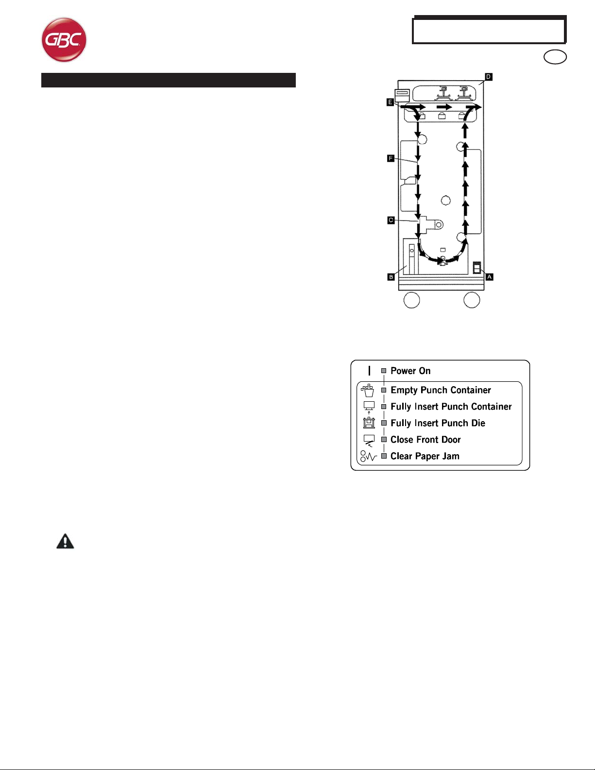
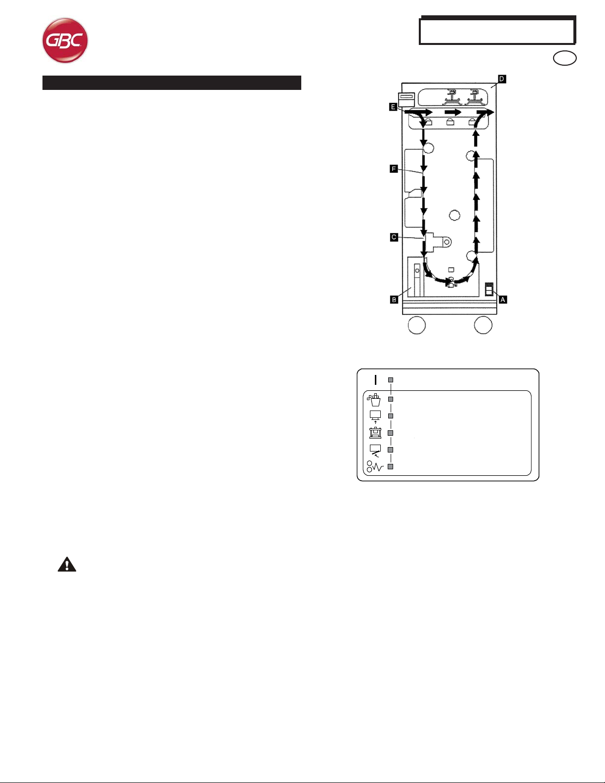
3. OPERA TION CONTROLS
A. On/Off Switch “I/O”
Must be in the “ON” position at all times
B. Punch Container:
Easy-to-access chip tray for quick chip disposal
C. Die Set Changes:
Are completed without tools and only take seconds to perform
D. Die Set Storage:
Holds up to 3 spare Die Sets
E. Punch Bypass:
Short straight-through paper path for unpunched documents
F. Punch Mode Path:
Wide radius turn can support stocks up to 216 g/m
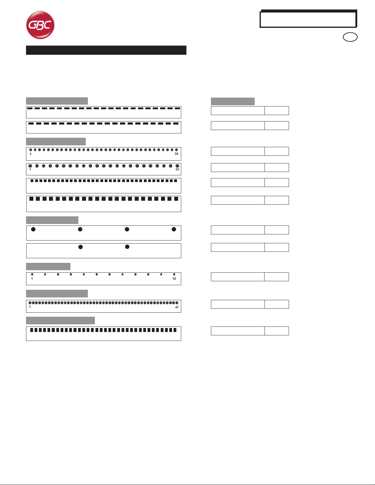
Located on the front of the AdvancedPunch is a panel that provides
information relating to the operational state of the punch unit. LED
lights indicate when the AdvancedPunch requires attention from the
operator.
1. Power On:
The green LED will illuminate when the power switch on the
AdvancedPunch is set to the on position. NOTE: The power cord
for the AdvancedPunch must be plugged into the appropriate power
source prior to setting the power switch to the on position.
2. Empty Punch Container:
When the punch container becomes full of waste paper chips, the
yellow LED will illuminate.
3. Fully Insert Punch Container:
When the punch container is removed or not fully inserted into
the punch unit, the yellow LED will illuminate.
4. Close Front Door:
When the front door is open or not completely closed the yellow
LED will illuminate.
5. Clear Paper Jam:
When a sheet of paper becomes jammed within the punch unit,
the yellow LED will illuminate. See the section of this manual titled
PAPER JAMS for instructions on how to remove a sheet that has
become jammed within the AdvancedPunch.
2
cover
AdvancedPunch
GB
NOTE: The LED lights on the AdvancedPunch will glow dimly
if the printer is turned on while the AdvancedPunch power
switch is in the off position. Af ter setting the AdvancedPunch
power switch to the on position, the LED lights will illuminate
to their full intensity.
5
Page 6
4. PUNCHING P ATTERNS
The AdvancedPunch uses a variety of easily interchangeable die
sets that allow you to punch documents in line for several different
binding styles. By selecting the appropriate die set, you can use your
AdvancedPunch to punch documents in any of the binding styles
indicated in Table 1.
AdvancedPunch
GB
For Plastic Comb Binding:
1
PB Plastic Bind; Hole Size: 8mm x 3.2mm (0.315" x 0.126") (LxW); Centre-to-Centre Hole Spacing: 14.3mm (0.563")
1
PB Plastic Bind; Australia Hole Size: 8mm x 3.2mm (0.315” x 0.126”)(LxW) Centre to Centre hole spacing: 14.3mm (0.563”)
21
20
For Twin Loop™ Binding:
W3 Wire; Round; 3 Holes per inch; Hole Size: 4mm (0.158") Diameter; Centre-to-Centre Hole Spacing: 8.5mm (0.335")
W2 Wire; Round; 2 Holes per inch; Hole Size: 6.5mm (0.256") Diameter; Centre-to-Centre Hole Spacing: 12.7mm (0.5")
1
W3 Wire; Square; Australia; 3 Holes per inch; Hole Size: 4mm x 4mm (0.158” x 0.158”) (L x W) Centre to Centre Hole Spacing:
8.5mm (0.335)”
1
W2 Wire; Square; Australia; 2 Holes per inch; Hole Size: 6.4mm x 5.5mm (0.252” x 0.217”) (L x W) Centre to Centre hole
spacing 12.7mm (0.5)
34
23
For Loose-leaf Binding:
1 4
4 Ring Binder; European (Standard Loose-leaf Patterns); Hole Size: 8mm (0.315") Diameter
2 Ring Binder; European (loose-leaf pattern), Hole Size: 8mm (0.315") Diameter
12
For Velo® Binding:
VB Velo® Bind Round; 1 Hole per inch Hole Size: 3.2mm ( 0.126") Diameter; Centre-to-Centre Hole Spacing: 25.4mm (1")
Xerox Part Number:
XEROX PB-21H, A4 498K19440
XEROX PB-20H, A4 498K19340
XEROX W3-34H-RND, A4 498K19370
XEROX W2-23H-RND, A4 498K19360
XEROX W3-34H-SQ, A4 498K19390
XEROX W2-23H-SQ, A4 498K19380
XEROX 4H-8mm, A4 498K19430
XEROX 2H-8mm, A4 498K19420
XEROX VB-12H, A4 498K19400
For Colour Coil™ Binding:
C4 Coil; Round; 4 Holes per inch; Hole Size: 4.5mm ( 0.177") Diameter; Centre-to-Centre Hole Spacing: 6.3mm (0.248")
ProClick® A4 34-Hole Binding:
1
PC ProClick®; Rectangular; 3 holes per inch, Hole size: 5.5mm (0.217"H) x 5.0mm (0.197"W). Centre to Centre 8.5mm (0.335")
Graphics do not represent actual punch pattern dimensions or spacing.
Please note that each punching style listed above requires a
separate die set for the AdvancedPunch. The AdvancedPunch can
hold up to four Die Sets in it’s cabinet (one in the operating slot and
three in the storage area).
To purchase additional or replacement Die Sets, contact your
authorized sales representative.
You cannot use die sets for the AdvancedPunch..
You can confirm the attached die set in the printer/copier.
XEROX C4-47H, A4 498K19350
34
6
XEROX PC-34H, A4 498K19410
Page 7
5. CHANGING THE INTERCHANGEABLE DIE SETS
Your AdvancedPunch offers the convenience of interchangeable die
sets, allowing you to economically punch documents for a wide variety
of binding styles. Changing the machine's die sets is both quick and
easy, as the following instructions illustrate:
Removing Die Sets from the Machine: The inter-changeable die
set slot of the AdvancedPunch is located on the left front side of the
machine. If a die set is already installed in your AdvancedPunch, you
can easily remove the die set by following these instructions:
Step 1: Stop the printer/copier.
Step 2: Open the AdvancedPunch access door panel.
Step 3: Securely grasp the handle and pull firmly. This firm pull
disengages the Automatic Latching Mechanism and allows the die set
to slide out.
Step 4: Continue to pull the handle until the Die Set is fully removed,
supporting it with both hands.
Step 5: Properly store the removed Die Set in the Die Set storage area
at the top of the AdvancedPunch (keep away from dust, dirt, accidental
falls from the edge of counters, etc.).
Step 6: Select the desired Die Set for your new job and slide it into the
Die Set slot. Push Die Set in firmly until it latches.
WARNING: POSSIBLE PINCH POINT HAZARD. WHEN
INSTALLING DIE SETS IN YOUR ADVANCEDPUNCH, AL WA YS
KEEP FINGERS AND OTHER BODY PARTS OUT OF THE
MACHINE’S DIE SET SLOT AND AW AY FROM ALL AREAS
OF THE DIE SET , EXCEPT FOR THE FINGER HOLE IN THE DIE
SET. FAILURE TO FOLLOW THESE PRECAUTIONS MAY
RESULT IN INJURY .
Step 7: Close the Access Door Panel.
Step 8: Proceed with your printing and punching job.
Please note that when using a new die some oil will be present
around the punched holes on the sheet. After punching 25 to 50
sheets the die will no longer leave oil on the sheets. It is recommended
that a short test print job be run after installing a new die or a die that
has recently been oiled.
6. PUNCHING OPERA TIONS
AdvancedPunch
GB
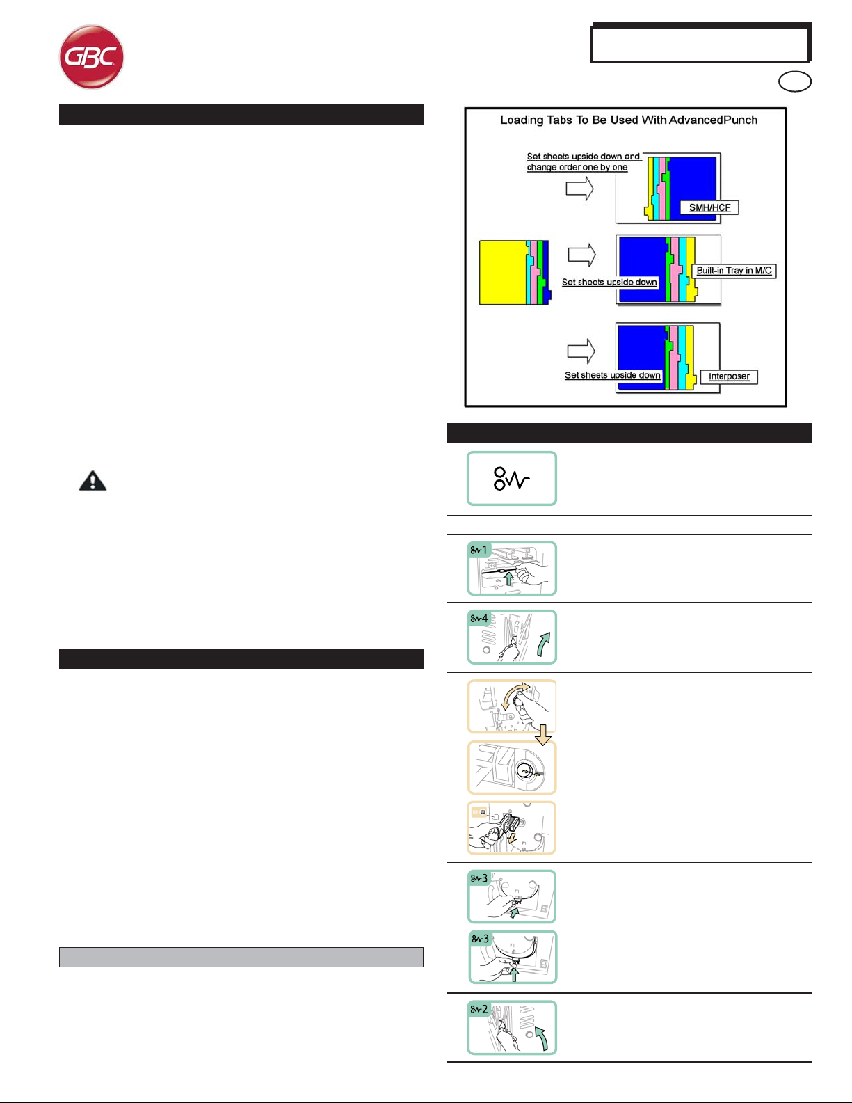
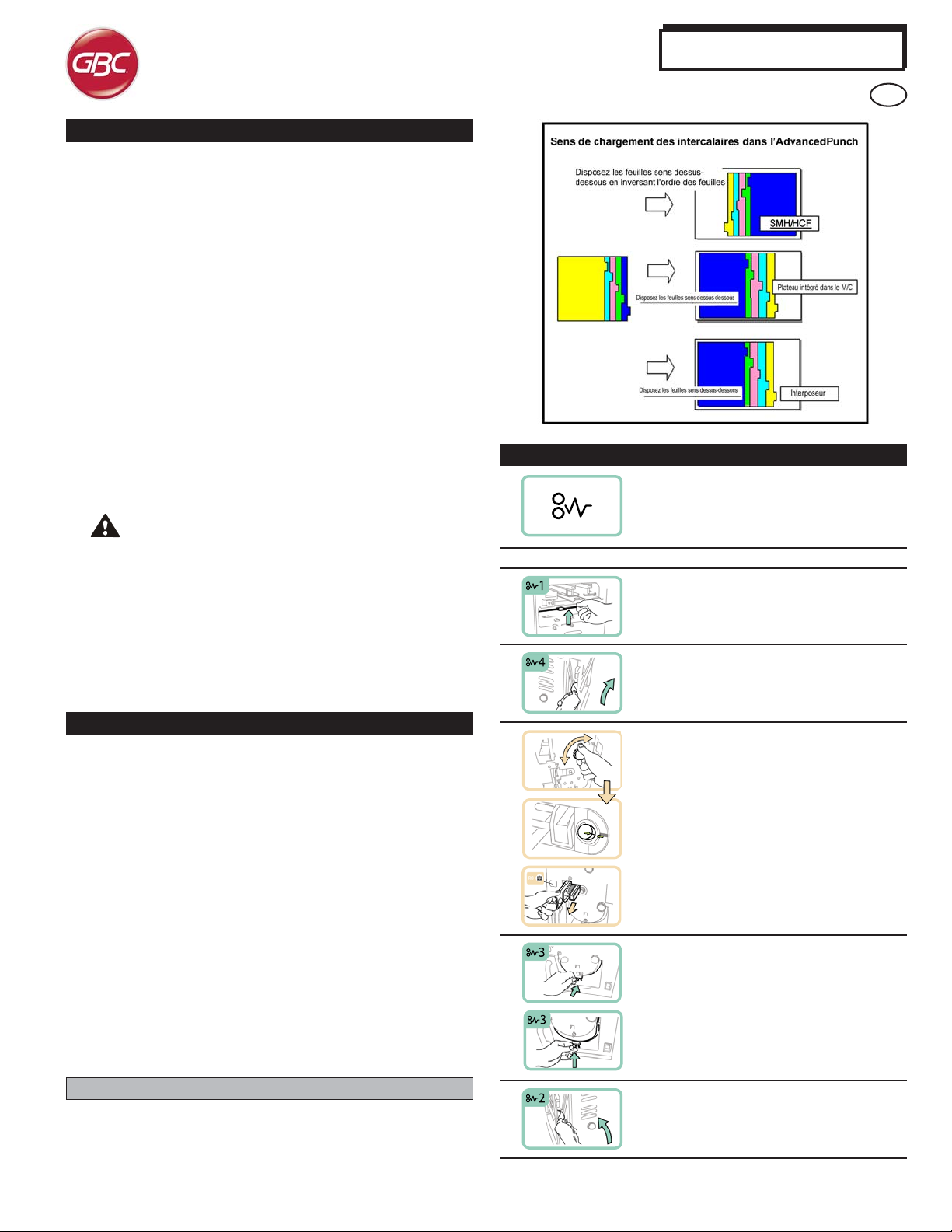
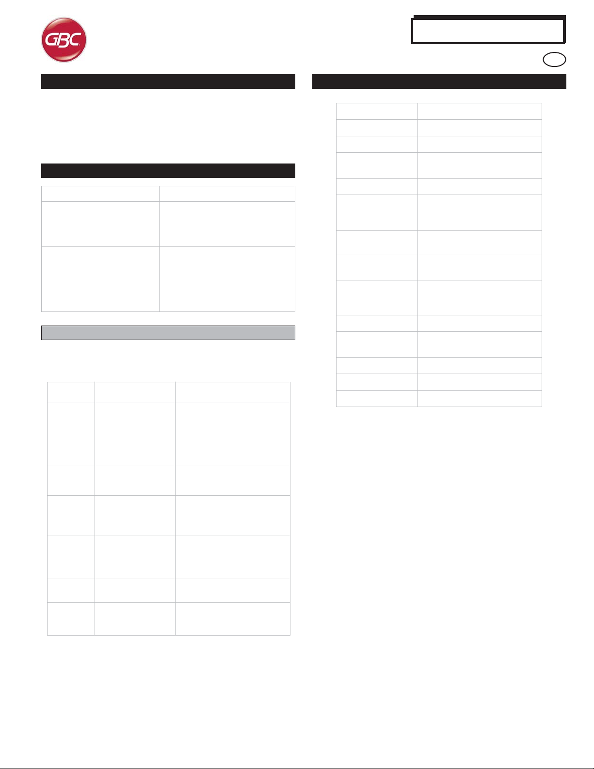
7. P APER JAMS
This symbol indicates a paper jam. To assist in
clearing paper jams in any of the following areas,
turn one or more of the small knobs to advance
the paper.
Area Description
If paper is jammed in the Punch Bypass, lift the
paper guide plate located just inside, reach in
and remove the jammed paper.
If paper is jammed in the downward paper path
chute, move the door to the right, reach in and
remove the jammed paper.
Prior to beginning a print job in which the punching feature of the
AdvancedPunch will be used, make certain that no yellow LED lights
are illuminated on the front panel of the AdvancedPunch. If a yellow
LED light is illuminated, then correct the fault prior to starting the punch
job. See section (3. OPERATION CONTROLS) for information regarding
the LED lights. The AdvancedPunch will not operate in punch mode if
any yellow LED is illuminated.
Prior to starting the punch job, check to make certain that the punch
die installed in the AdvancedPunch is the correct die/hole pattern for
the job. If the die is not the correct die, then replace it at this time.
To enable the AdvancedPunch punching feature, use the printer user
interface screen. Follow the steps below to enable the punch feature.
Using the printer user interface screen, go to the Copy menu. Then
select Copy Output to enter the Hole Punch & More menu. Once in
this menu an option will appear in the hole punch column titled
AdvancedPunch. Select this option, then press Save to return to the
Copy menu. The AdvancedPunch will now operate in the punch mode.
Punching Tabs
The AdvancedPunch punches the leading edge of a sheet. Because
of this Tabs must be fed with the tab on the trailing edge. The manner
in which Tabs are loaded into the tray to cause the correct tab-trailing
feeding varies depending upon the tray that is utilized.
If paper is jammed or the Die Set is jammed, turn
Knob J3 to the HOME position, (arrows line up)
slide the Die Set out and remove paper.
If paper is jammed in the bottom chute of the
Punch Paper path, press the bottom chute latch,
reach in and remove any jammed paper.
If paper is jammed in the upward paper path
chute, move the door to the left, reach in and
remove the jammed paper.
7
Page 8
AdvancedPunch
GB
8. PUNCH CONT AINER
The Punch Container for your AdvancedPunch is located at the front
of the machine’s base. The drawer should periodically be pulled out
and emptied. The AdvancedPunch uses a sensor to determine when
the punch container is full. Once the punch container becomes full
the LED light on the front panel of the AdvancedPunch will illuminate
and a message will appear on the printers user interface screen.
9. PROBLEM SOL VING
Probable Cause
No power, won’t punch
Die Set will not come out using
a moderate pull
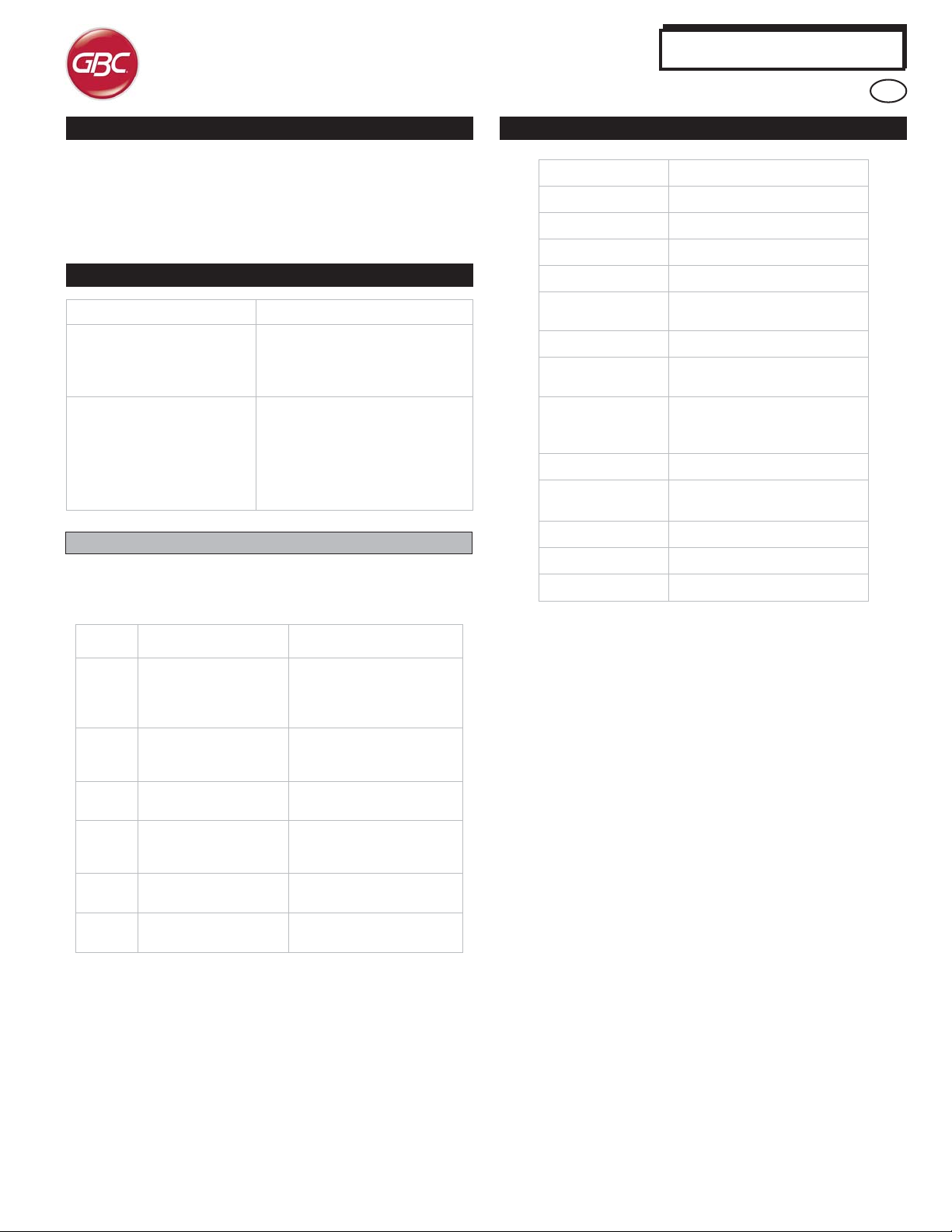
Fault Codes
Fault codes for the AdvancedPunch are displayed on the machine's UI
as an AdvancedPunch fault code. Listed below are fault codes that
apply specifically to the AdvancedPunch product.
Probable Cause
Power cord not attached to back of
machine or not properly plugged into
the wall Power On/Off Switch not
activated
The Die Set is in partial cycle. Turn
the Die Set knob (J3) to the HOME
position. Home position is when the
arrows line up. The Die Set should
now slide out easily.
Also see Paper Jams.
10. SPECIFICA TIONS
Speed
Punch Sheet Size
Punch Edge
Paper Stock
Paper Bypass Mode
Sheet size
Punch Capacity
Power Supply
Electrical
Safety
Dimensions
Weight
Shipping Weight
Manufactured
230V Machines
Up to 127 sheets per minute
A4 - 210mm x 297mm
297mm
20# bond to 80# cover
Paper sizes and stocks same as
printer
Single Sheet
230V, 50Hz,
Single Phase
BTUs/Hour 1024BTU/HR
Watts 300W
Amps 1.3A
TUV/GS, CE
12” (30.5cm) (W) x 38.5” (97.8cm)
(H) x 28.5” (72.3cm) (D)
154 lbs. (70 Kg)
254 lbs. (115.5 Kg)
Assembled in T aiwan
Fault
Code
040-100
040-101
040-900
040-901
040-300
040-940
040-941
040-942
140-700
Possible Cause Recommended Solution
Jam is detected in
AdvancedPunch.
Front door of
AdvancePunch is not
closed.
Dieset is missing or not
fully installed.
Punch container is
mising or not fully
installed
Punch container is full.
Punch container is
near full.
Open front door and
inspect for paper jam.
Remove papaerjam if found,
then close front door.
Close front door of
AdvancedPunch.
Install dieset or fully insert
dieset, then close front door.
Install and/or fully insert
punch container, then close
front door.
Empty punch container and
then re-install.
Empty punch container and
then re-install.
8
Page 9
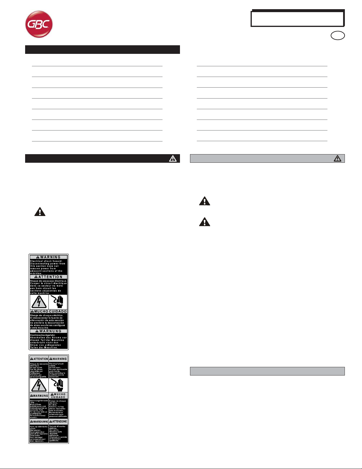
Table des matières
AdvancedPunch
F
1. CONSIGNES DE SÉCURITÉ 9
Consignes importantes 9
Nettoyage 9
Entretien 10
Messages de sécurité 10
2. INTRODUCTION 10
3. COMMANDES 11
4. MODÈLES DE PERFORATION 12
1. CONSIGNES DE SÉCURITÉ
VOTRE SÉCURITÉ ET LA SÉCURITÉ DES PERSONNES QUI VOUS
ENTOURENT SONT TRÈS IMPOR TANTES POUR GBC. LES CONSIGNES
ET MESSAGES DE SÉCURITÉ ESSENTIELS DÉLIVRÉS DANS LE
PRÉSENT MANUEL APP ARAISSENT ÉGALEMENT SUR LA MACHINE.
VEUILLEZ LIRE A TTENTIVEMENT CE MANUEL A V ANT D’UTILISER LA
MACHINE.
DANS CE MANUEL D’UTILISA TION, VOUS TROUVEREZ UN
SYMBOLE D’AVER TISSEMENT EN REGARD DE CHAQUE
MESSAGE DE SÉCURITÉ. CE SYMBOLE SIGNALE UN RISQUE
POTENTIEL. VOUS POURRIEZ VOUS BLESSER, BLESSER
UN TIERS OU ENDOMMAGER LE PRODUIT .
VOUS TROUVEREZ LES ÉTIQUETTES SUIVANTES SUR
L‘ADVANCEDPUNCH:
Ce message de sécurité indique que vous
pouvez recevoir un choc électrique, car
débrancher le courant de cette section ne
coupe pas le courant des sections adjacentes
de la machine.
5. CHANGEMENT DE MATRICE 13
6. PERFORATION 13
Perforation d’intercalaires 13
7. INCIDENTS PAPIER 13
8. RÉSERVOIR À CONFETTIS 14
9. EN CAS DE PROBLÈME 14
Codes de panne 14
10. SPÉCIFICATIONS 14
Consignes importantes
Utilisez l’AdvancedPunch uniquement pour perforer le papier et
les couvertures conformément aux spécifications indiquées.
Gardez ce manuel d’utilisation à portée de main.
ATTENTION: L’INTERRUPTEUR MARCHE/ARRÊT DE
L’IMPRIMANTE NE MET PAS LA PERFORATRICE HORS
TENSION.
ATTENTION: L’INTERRUPTEUR MARCHE/ARRÊT DE LA
PERFORATRICE NE MET PAS L ’IMPRIMANTE HORS TENSION.
La tension d’alimentation de l’AdvancedPunch doit correspondre
aux caractéristiques électriques de la machine (elles sont
indiquées sur l’étiquette du numéro de série).
Une prise de terre est prévue par mesure de sécurité. Elle doit
être raccordée à une prise électrique prévue à cet effet. Si vous
ne parvenez pas à introduire la fiche dans la prise, faites appel à
un électricien qualifié pour qu’il installe une prise adéquate.
Ne modifiez pas la fiche située au bout du cordon d’alimentation
de l’AdvancedPunch (si elle est fournie). Elle a été conçue pour
votre sécurité.
Débranchez l’AdvancedPunch avant de déplacer la machine ou si
vous prévoyez de ne pas l’utiliser durant une longue période.
N’utilisez pas l‘AdvancedPunch si le cordon ou la fiche
d’alimentation de la machine est endommagé. N’utilisez pas la
machine après un quelconque dysfonctionnement. Ne mettez pas
la machine sous tension si vous avez renversé un liquide ou si
elle est endommagée de quelque façon que ce soit.
Ne surchargez pas les prises électriques. Cela pourrait provoquer
un incendie ou une décharge électrique.
Ce message signale qu'une décharge
électrique pourrait vous blesser gravement,
voire vous tuer si vous ouvrez la machine. Ne
retirez JAMAIS les plaques vissées sur les
couvercles de la machine. Faites TOUJOURS
confiance au personnel d’entretien qualifié.
Nettoyage
Vous pouvez nettoyer la surface externe de l’AdvancedPunch à
l’aide d’un chiffon doux et humide.
N’utilisez pas de détergent ou de solvants, car vous pourriez
endommager la machine.
9
Page 10
AdvancedPunch
F
Messages de sécurité
SÉLECTION DU CORDON D’ALIMENTA TION SECTEUR
(LE PARAGRAPHE SUIVANT NE S’APPLIQUE QU’AUX MODÈLES
ALIMENTÉS PAR UN COURANT DE 230V 50HZ UTILISÉS DANS L’UNION
EUROPÉENNE.)
ATTENTION: LORSQUE VOUS CHOISISSEZ UN CORDON
D’ALIMENTATION AMOVIBLE POUR VOTRE
ADVANCEDPUNCH, RESPECTEZ TOUJOURS LES
PRÉCAUTIONS SUIVANTES.
Le cordon est constitué de trois parties: la fiche, le cordon et la
connexion à la machine. Chacun de ces composants dispose de
l’homologation européenne requise en matière de sécurité.
Les caractéristiques électriques minimales applicables au cordon sont
publiées pour des raisons de sécurité.
N’UTILISEZ PAS DE CORDONS NE RESPECTANT PAS LES
EXIGENCES ÉLECTRIQUES MINIMALES SUIVANTES.
FICHE: 3 A, 250V, 50/60Hz, Classe 1, à 3 conducteurs, homologuée
par l'Union Européenne.
CORDON: Type H05VV -F3G0.75, harmonisé (< HAR>). Les symboles
«< >» indiquent que le cordon est homologué conformément à la norme
européenne appropriée (REMARQUE: «HAR» équivaut à la marque
d’homologation de l’agence de sécurité européenne qui a approuvé le
cordon. Exemple: «< VDE >»).
CONNECTEUR DE L’APPAREIL: 3 A, 250V, 50/60Hz, homologué par
l’Union Européenne, type IEC 320. Le cordon ne doit pas excéder 3 m
de long. Vous pouvez remplacer le cordon électrique par un câble
d'alimentation présentant des caractéristiques électriques supérieures
aux minima indiqués.
Entretien, AdvancedPunch
Ne tentez pas de réparer votre AdvancedPunch par vous-même.
Contactez un représentant agréé pour effectuer les réparations ou le
gros entretien de votre AdvancedPunch.
NE RETIREZ PAS LES COUVERCLES DE LA MACHINE.
AUCUNE pièce interne ne peut être remplacée par l’utilisateur. Les
risques de blessure et/ou d’endommagement de la machine sont ainsi
éliminés.
Entretien des matrices
Chaque matrice doit être soigneusement lubrifiée en usine avant d’être
livrée au client. Dans des conditions normales d’utilisation, ce lubrifiant
disparaît progressivement et doit être remplacé. Dans le cadre de
l’entretien de routine de l’appareil, chaque matrice doit être lubrifiée
après environ 50,000 cycles de perforation. GBC recommande d'utiliser
de l’huile 3-IN-ONE disponible chez tous les bons revendeurs. D’autres
huiles pour machine légère peuvent également être utilisées.
Pour lubrifier la matrice, il suffit d’appliquer une petite goutte d’huile
sur toute la longueur de la bande de feutrine située sur la matrice. Une
fois l’huile appliquée, réinstallez la matrice dans l’AdvancedPunch et
effectuez un petit test d’impression. À noter qu’il est tout à fait normal
que de l’huile soit présente sur le premier jeu de feuilles perforé après
avoir lubrifié la matrice. Au bout d’environ 25 à 50 feuilles, toute trace
d’huile sur les feuilles perforées aura disparu. L’AdvancedPunch peut
désormais être utilisé pour perforer des travaux d’impression.
Messages de sécurité
NOTE FCC
(LE PARAGRAPHE SUIVANT NE S’APPLIQUE QU’AUX MODÈLES
ALIMENTÉS PAR UN COURANT DE 115V 60HZ.)
Cet équipement a été testé et il satisfait aux normes relatives aux
appareils numériques de Classe A, conformément à la Partie 15 des
règles FCC. Ces limites ont été prévues pour garantir une protection
raisonnable contre les interférences nocives lors de l’utilisation de
l’équipement dans une zone de travail.
Cet équipement génère, utilise et irradie des ondes radio. Par
conséquent, si vous ne l’installez pas ou ne l’utilisez pas conformément
au manuel d’utilisation, vous risquez de provoquer des interférences
dans les communications par radio. L’utilisation de cet équipement
dans une zone habitée risque de provoquer des interférences. Dans
ce cas, vous devrez corriger ces interférences à vos frais.
ATTENTION: LE F AIT D'EFFECTUER UNE MODIFICA TION
OU UN CHANGEMENT SANS L'ACCORD EXPLICITE DE
GENERAL BINDING CORPORATION ANNULE VOTRE
DROIT D’UTILISER L’ÉQUIPEMENT .
Canada Class A Notice - Avis Canada, Classe A
Cet appareil numérique de Classe A est conforme à la norme
canadienne ICES-3.
Cet appareil numérique de la classe A est conforme à la norme
canadienne NMB-003.
2. INTRODUCTION
Nous tenons à vous remercier d’avoir acheté un AdvancedPunch. Ce
système de production polyvalent vous permettra de perforer des
documents de nombreuses manières en remplaçant tout simplement
le bloc à colonnes. Cet appareil a été conçu dans un souci de simplicité
d'utilisation.
L’AdvancedPunch est une solution innovante pour perforer le papier.
Il offre en outre les caractéristiques suivantes:
Les blocs à colonnes peuvent être remplacés rapidement sans outil
ni levier.
Tous les blocs à colonnes de l’AdvancedPunch disposent d’une
étiquette d'identification indiquant la configuration de perforation et
son nom.
Une zone de stockage des matrices de rechange a été aménagée
au-dessus du By-pass.
10
Page 11
3. COMMANDES
A. Interrupteur marche/arrêt: “I/O”
Il doit être en position “ON” à tout moment
B. Réservoir à confettis:
Plateau facile d’accès permettant une évacuation rapide des
confettis
C. Changement de blocs à colonnes:
Facile, sans outil et en quelques secondes
D. Stockage des matrices:
Prévu pour stocker jusqu’à trois matrices
E. By-pass perforatrice:
Chemin papier court et direct pour les documents non perforés
F. Chemin papier en mode perforation:
Le grand rayon de la courbe permet d’utiliser des supports d’un
grammage allant jusqu’à 216 g/m
L’avant de l’AdvancedPunch comporte un panneau qui fournit des
informations concernant l’état de fonctionnement de la perforatrice.
Un voyant s’allume lorsque l’AdvancedPunch requiert l’attention de
l’opérateur.
1. Marche:
Le voyant vert s’allume lorsque le bouton marche/arrêt de
l’AdvancedPunch est placé en position « on » (marche).
REMARQUE : le cordon d’alimentation de l’AdvancedPunch doit
être branché sur une prise murale adaptée avant de mettre le
bouton marche/arrêt en position « on » (marche).mpel.
2. Réservoir à confettis plein:
Lorsque le réservoir à confettis est plein, le voyant jaune s’allume.
3. Réservoir à confettis mal inséré:
Lorsque le réservoir à confetti a été retiré ou est mal inséré dans
le module de perforation, le voyant jaune s’allume.
4. Porte avant ouverte ou mal refermée:
Lorsque la porte avant est ouverte ou mal refermée, le voyant
jaune s’allume.
5. Incident papier:
Lorsqu’une feuille de papier se coince dans le module de
perforation, le voyant jaune s’allume. Consultez la section
INCIDENTS PAPIER du présent manuel pour plus d’instructions
concernant la manière de retirer une feuille coincée dans
l’AdvancedPunch.
REMARQUE: Les voyants de l’AdvancedPunch s’allument
avec une faible intensité si l’imprimante est mise sous tension
alors que l'interrupteur marche/arrêt de l’AdvancedPunch
est en position « off » (arrêt). Une fois l'interrupteur marche/
arrêt de l’AdvancedPunch en position « on » (marche), les
voyants s’allument avec une intensité lumineuse normale.
2
.
AdvancedPunch
F
Marche
Réservoirà confettis plein
Réservoirà confettis mal inséré
Matrice de perforation mal insérée
Porte avant ouverte ou mal refermée
Incident papier
11
Page 12

4. MODÈLES DE PERFORA TION
L’AdvancedPunch utilise une grande variété de matrices faciles à
remplacer afin de perforer les documents en fonction des différents
styles de reliure. En sélectionnant la matrice appropriée, vous pouvez
utiliser votre AdvancedPunch pour perforer les documents en fonction
des différents styles indiqués dans le tableau 1.
AdvancedPunch
F
Pour une reliure à anneaux plastiques:
1
PB Plastic Bind; taille de l’orifice: 8 mm (0,315") (L) x 3,2 mm (0,126") (l); distance entre les orifices (de centre à centre):
14,3 mm (0,563")
1
PB Plastic Bind; Australie taille de l’orifice: 8 mm (0,315") (L) x 2,9 mm (0,126") (l); distance entre les orifices (de centre à
centre): 14,3 mm (0,563")
Pour une reliure Twin Loop™:
W3 Wire; Rond; 3 orifices par pouce; Taille de l’orifice: 4mm (0,158") de diamètre; Distance entre les orifices (de centre à
centre): 8,5mm (0,335")
W2 Wire; Rond; 2 orifices par pouce; Taille de l’orifice: 6,5mm (0,256") de diamètre; Distance entre les orifices (de centre à
centre): 12,7mm (0,5")
1
W3 Fil; Carré; Australie; 3 trous par pouce; taille de trou: 4mm x 4mm (0,158" x 0,158") (L x L) Espacement de trou entre
centres: 8,5mm (0,335")
1
W2 Fil; Carré; Australie; 2 trous par pouce; taille de trou: 6,4mm x 5,5mm (0,252" x 0,217") (L x L) Espacement de trou entre
centres: 12,7mm (0,5")
Pour une reliure à feuillets mobiles:
1 4
4 Reliure à anneaux; Européen (modèles standard de feuillets mobiles); T aille de l’orifice: 8mm (0,315") de diamètre
2 Reliure à anneaux; Européen (feuillet mobile), Taille de trou: 8mm (0,315") Diamètre
12
Pour une reliure VeloBind®:
Réf. Xerox:
21
20
XEROX PB-21H, A4 498K19440
XEROX PB-20H, A4 498K19340
XEROX PB-20H, A4 498K19340
XEROX W2-23H-RND, A4 498K19360
34
23
XEROX W3-34H-SQ, A4 498K19390
XEROX W2-23H-SQ, A4 498K19380
XEROX 4H-8mm, A4 498K19430
XEROX 2H-8mm, A4 498K19420
VB VeloBind®; rond; 1 orifice par pouce; taille de l’orifice: 3,2 mm (0,125") de diamètre; distance entre les orifices (de centre à
centre): 25,4 mm (1")
Pour une reliure Color Coil™:
C4 Coil; rond; 4 orifices par pouce; taille de l’orifice: 4,5 mm (0,177") de diamètre; distance entre les orifices (de centre à centre):
6,3 mm (0,248")
Reliure à trous-ProClick® A4 34:
1
PC ProClick®, Rectangulaire; 3 trous par puce, taille de trou: 5,5mm (0,217"H) x 5,0mm (0,197"L).
Entre centres: 8,5mm (0,335")
Les modèles de perforation représentés sur les illustrations ne sont pas à l’échelle.
Remarquez que chacun des styles repris dans le tableau ci-dessus
exige l’utilisation d’une matrice différente sur le AdvancedPunch. Le
AdvancedPunch peut héberger jusqu’à 4 matrices (une dans la
fente de travail et trois dans la zone de stockage.)
Pour obtenir des matrices de remplacement ou des matrices
différentes, veuillez contacter votre revendeur agréé.
XEROX VB-12H, A4 498K19400
XEROX C4-47H, A4 498K19350
34
XEROX PC-34H, A4 498K19410
12
Page 13
5. CHANGEMENT DE MA TRICE
Votre AdvancedPunch utilise des matrices interchangeables, ce qui vous
permet de perforer, à moindres frais, les documents en fonction de
différents styles de reliure. Le remplacement des matrices de la machine
est rapide et facile. Pour ce faire, suivez les instructions suivantes:
Retrait des matrices de la machine: La fente des matrices
interchangeables de l’AdvancedPunch est située sur la droite, à l’avant
de la machine. Si une matrice est déjà installée dans votre
AdvancedPunch, vous pouvez facilement la retirer en procédant
comme suit:
Étape 1: Arrêtez l’imprimante/copieur.
Étape 2: Ouvrez la porte d’accès à l’AdvancedPunch.
Étape 3: Tenez fermement la poignée et tirez. Ce faisant, vous
déclenchez le loquet automatique et vous pouvez retirer la matrice.
Étape 4: Continuez de tirer la poignée jusqu’à ce que le bloc à colonnes
soit complètement retiré, en le soutenant avec les deux poignées.
Étape 5: Rangez la matrice dans la zone de stockage située en haut
de l’AdvancedPunch (protégez-la de la poussière, des chutes
accidentelles, etc.).
Étape 6: Choisissez une matrice appropriée pour le travail que vous
souhaitez accomplir et placez-la dans la fente pour matrices. Poussez
la matrice jusqu’à ce qu’elle s’enclenche.
ATTENTION: F AITES ATTENTION DE NE P AS VOUS COINCER
LES DOIGTS. LORS DE LA MISE EN PLACE DE LA MA TRICE
DANS L’ADV ANCEDPUNCH, ÉLOIGNEZ VOS DOIGTS DE LA
FENTE POUR MATRICE ET NE TENEZ LA MA TRICE QU’À L’AIDE
DE L’ORIFICE PRÉVU À CET EFFET. SOYEZ PRUDENT, CAR
VOUS POURRIEZ VOUS BLESSER.
Étape 7: Fermez la porte d’accès.
Étape 8: Poursuivez votre travail d’impression/perforation.
À noter que lorsque vous utilisez une matrice neuve, quelques traces
d’huile peuvent être présentes autour des trous de perforation de la
feuille. Après environ 25 à 50 feuilles, la matrice ne laissera plus
aucune trace d’huile sur les feuilles. Il est recommandé d’effectuer un
court test d’impression après avoir installé une matrice neuve ou
récemment lubrifiée.
7. INCIDENTS P APIER
Ce symbole indique un incident papier. Pour
éliminer un incident papier dans une des zones
suivantes, tournez la (ou les) manette(s)
nécessaires pour faire avancer le papier.
Zone
Si l'incident papier se produit au niveau du Bypass, relevez la plaque de guidage du papier
située à l’intérieur et retirez les restes de papier.
Si l'incident se produit au niveau de la descente
du chemin papier, poussez la porte vers la droite
et retirez les restes de papier.
AdvancedPunch
F
Description
6. PERFORA TION
Avant de commencer un travail d’impression impliquant l’utilisation de
la fonction de perforation de l’AdvancedPunch, assurez-vous
qu’aucun voyant jaune n’est allumé sur le panneau avant de
l’AdvancedPunch. Si un voyant jaune est allumé, résolvez la panne
avant de commencer le travail de perforation. Consultez la section (3.
COMMANDES) pour plus d’informations concernant les voyants.
L’AdvancedPunch ne fonctionnera pas en mode Perforation si un
voyant jaune est allumé.
Dans l’écran de l’interface utilisateur de l’imprimante, allez dans le
menu Copier. Puis, sélectionnez Sortie copie pour accéder au menu
Perforation et autres. Dans ce menu, l’option AdvancedPunch
apparaît dans la colonne perforation. Sélectionnez cette option, puis
appuyez sur Enregistrer pour revenir au menu Copier.
L’AdvancedPunch fonctionne maintenant en mode Perforation.
Perforation d’intercalaires
L’AdvancedPunch perfore le bord d’attaque des feuilles. De ce fait,
les intercalaires doivent être chargés en veillant à ce que les onglets
se trouvent sur le bord de queue. La manière dont les Intercalaires
sont chargés dans le plateau de manière à être perforés du bon côté
varie en fonction du plateau utilisé.
Si l'incident papier se produit au niveau de la
matrice, tournez la manette J3 en position initiale
(les flèches s’alignent), retirez la matrice et
éliminez les restes de papier.
Si l'incident papier se produit dans la partie
basse du chemin papier, appuyez sur le loquet
du canal et retirez les restes de papier.
Si l'incident papier se produit dans la montée du
chemin papier, poussez la porte vers la gauche
et retirez les restes de papier.
13
Page 14
AdvancedPunch
F
8. RÉSERVOIR À CONFETTIS
Le réservoir à confettis de votre AdvancedPunch est situé à l’avant
de la base de la machine. Le tiroir doit être périodiquement retiré et
vidé. Un capteur permet à l’AdvancedPunch de savoir lorsque le
réservoir à confettis est plein. Lorsque tel est le cas, le voyant
situé sur le panneau avant de l’AdvancedPunch s’allume et un
message apparaît sur l’écran de l'interface utilisateur.
9. EN CAS DE PROBLÈME
Problème
Hors tension, la perforatrice
ne fonctionne pas
La matrice ne peut pas être
extraite en tirant en douceur
Codes de panne
Les codes de panne de l’AdvancedPunch s’affichent sur l’interface
utilisateur de la machine. Voici les codes de panne spécifiques à
l’AdvancedPunch.
Code de
panne
040-100
040-101
040-900
Cause possible Solution préconisée
Un incident papier
s’est produit dans
l’AdvancedPunch.
040-901
040-300
La porte avant de
l’AdvancedPunch
n’est pas fermée.
040-940
La matrice de
perforation est
absente ou mal
insérée.
040-941
Le réservoir à
confettis est absent
ou mal inséré
040-942
140-700
Le réservoir à
confettis est plein.
Le réservoir à
confettis est
presque plein.
Cause possible
Le cordon d’alimentation n’est pas
correctement branché au secteur.
La touche marche/arrêt n’est pas
activée
La matrice est en cours d’utilisation.
Tournez le bouton de la matrice (J3)
en position initiale. Pour ce faire,
alignez les flèches. Retirez alors la
matrice.
Voir aussi les incidents papier.
Ouvrez la porte avant et
recherchez les feuilles de
papier coincées. Le cas
échéant, retirez le papier
coincé, puis refermez la porte
avant.
Refermez la porte avant de
l’AdvancedPunch.
Installez ou insérez
complètement une matrice, puis
refermez la porte avant.
Installez et/ou insérez
complètement un réservoir à
confettis, puis refermez la
porte avant.
Videz le réservoir à confettis,
puis remettez-le en place.
Videz le réservoir à confettis,
puis remettez-le en place.
10. SPÉCIFICA TIONS
Vitesse
Taille de la Feuille
Contour du
Perforateur
Papier Support
Mode de
Contournement du
Papier
Capacité du
Perforateur
Alimentation
Puissance
Sécurité
Dimensions
Poids
Poids à l’expédition
Fabriqué
Modèles 230V
Jusqu’à 127 feuilles par minute
A4 - 210mm x 297mm
297mm
20# bond à 80# couverture
Tailles du papier et mêmes stocks
que l’imprimante
Feuille à Feuille
230V, 50Hz,
Monophasé
BTU/heure 102 4BT U/h
Watts 300W
Ampères 1.3A
TUV/GS, CE
12" (30.5cm) (W) x 38.5" (97.8cm)
(H) x 28.5" (72.3cm) (D)
154 lbs. (70 Kg)
254 lbs. (115.5 Kg)
Assemblé à Taiwan
14
Page 15
ÍNDICE
AdvancedPunch
E
1. INSTRUCCIONES DE SEGURIDAD 15
Instrucciones importantes 15
Limpieza 15
Reparación 16
Avisos de seguridad 16
2. INTRODUCCIÓN 16
3. MANDOS DE OPERACIÓN 17
4. PA TRONES DE PERFORACIÓN 18
1. INSTRUCCIONES DE SEGURIDAD
SU SEGURIDAD Y LA DE LAS PERSONAS QUE LE RODEAN SON MUY
IMPORT ANTES P ARA GBC. LOS MENSAJES E INTRUCCIONES DE
SEGURIDAD IMPORT ANTES AP ARECEN EN ESTE MANUAL Y EN LA
MÁQUINA. LEA A TENT AMENTE ESTE MANUAL ANTES DE USAR LA
MÁQUINA.
EN ESTE MANUAL DE USO ENCONTRARÁ UN SÍMBOLO DE
ADVERTENCIA EN CADA MENSAJE DE SEGURIDAD. ES TE
SÍM BOL O INDICA UN RIES GO PO TE NCIAL: PODRÍA
LESIONARSE, LESIONAR A TERCEROS O DAÑAR EL
PRODUCTO.
LAS SIGUIENTES ETIQUETAS AP ARECEN EN EL ADV ANCEDPUNCH:
Este mensaje de seguridad le alerta que puede
recibir una descarga eléctrica aunque haya
desconectado la corriente en esta sección,
ya que la corriente no está desconectada en
las secciones adyacentes.
5. SUSTITUCIÓN DE LOS JUEGOS DE TROQUELES 19
6. PERFORACIÓN 19
Perforación de pestañas 19
7. AT ASCOS DE P APEL 19
8. CONTENEDOR DEL PAPEL 20
9. SOLUCIÓN DE A VERÍAS 20
Códigos de fallas 20
10. ESPECIFICACIONES 20
Instrucciones importantes
Use el AdvancedPunch únicamente para perforar el papel y la
cubierta de acuerdo con las especificaciones indicadas.
Conserve este manual de instrucciones para usos en el futuro.
PRECAUCIÓN: EL INTERRUPTOR PARA ENCENDER O
APAGAR LA IMPRESORA NO DESCONECTA LA
PERFORADORA.
PRECAUCIÓN: EL INTERRUPTOR PARA ENCENDER O
APAGAR LA PERFORADORA NO DESCONECTA LA
IMPRESORA.
La tensión de alimentación del AdvancedPunch debe corresponder
a las características eléctricas de la máquina (están indicadas en
la etiqueta del número de serie).
La máquina dispone de una toma de tierra para garantizar su
seguridad. Debe conectarse a un enchufe adecuado para toma
de tierra. Si no consigue conectar el enchufe a la toma, contacte
a un electricista calificado para que instale una toma adecuada.
No modifique el conector del cable de alimentación del
AdvancedPunch (en caso de haberlo). Se ha diseñado para
garantizar su seguridad.
Desconecte el AdvancedPunch si desea desplazar la máquina o
si no la va a usar durante un largo periodo
No use el AdvancedPunch si el cable o la toma de alimentación de
la máquina están dañados. No use la máquina en caso de avería,
derrame de algún líquido o si está dañada.
No sobrecargue la toma de alimentación. Podría provocar un
incendio o una descarga eléctrica.
Este mensaje señala que una descarga
eléctrica podría lesionarle gravemente e
incluso provocarle la muerte si abre la
máquina. NUNCA retire las placas atornilladas
en las tapas de la máquina. Refiera SIEMPRE
los requisitos del servicio al servicio
cualificado personal.
Limpieza
Puede limpiar la superficie externa del AdvancedPunch con un
trapo suave y húmedo.
No use detergente ni disolventes, ya que podría dañar la máquina.
15
Page 16

AdvancedPunch
E
Avisos de seguridad
SELECCIÓN
(LA SECCIÓN SIGUIENTE SÓLO ES VÁLIDA PARA LAS UNIDADES
230V 50/60HZ UTILIZADAS EN LA UNIÓN EUROPEA)
PRECAUCIÓN: A LA HORA DE SELECCIONAR UN CABLE
DE ALIMENTACIÓN AMOVIBLE PARA SU
ADVANCEDPUNCH, RESPETE SIEMPRE LAS
PRECAUCIONES SIGUIENTES.
El cable está compuesto por tres partes: el enchufe, el cable y la
conexión a la máquina. Cada uno de esos componentes dispone de la
homologación europea para la seguridad.
A continuación le indicamos las características eléctricas
correspondientes al cable de alimentació..
NO USE CABLES QUE NO RESPETEN LAS EXIGENCIAS ELÉCTRICAS
MÍNIMAS AQUÍ MENCIONADAS.
ENCHUFE: 3 amperios, 250 voltios, 50/60 Hz, Clase 1,3 conductores,
homologado por la Unión Europea.
CABLE: Tipo H05VV-F3G0.75, armonizado (< HAR >). Los símbolos
“< >” indican que el cable ha sido homologado de acuerdo con la
norma europea correspondiente (NOTA: “HAR” equivale a la marca
de homologación de la agencia de seguridad europea que aprobó el
cable. Ejemplo: “< VDE >”).
CONEXIÓN A LA MÁQUINA: 3 amperios, 250 voltios, 50/60 Hz,
homologado por la Unión Europea, Tipo IEC 320. El cable no debe
sobrepasar 3 metros de largo. Puede sustituir el cable por uno que
tenga las características eléctricas superiores a las mínimas aquí
especificadas.
Reparación, AdvancedPunch
No trate de reparar su AdvancedPunch por su cuenta. Contacte a un
representante certificado para efectuar reparaciones o el
mantenimiento de su AdvancedPunch.
Avisos de seguridad
NOTA SOBRE LA FCC
(LA SECCIÓN SIGUIENTE SÓLO ES VÁLIDA PARA LAS UNIDADES
115V 60HZ.)
Este equipo ha sido probado y satisface las normas relativas a los
aparatos digitales de la Clase A (Parte 15 de las normas de la FCC). Se
han previsto esos límites para garantizar una protección razonable
contra las interferencias durante el uso del equipo en un entorno
comercial.
Este equipo genera, usa y emite ondas de radio. Por lo tanto, si no lo
instala o si no lo usa de acuerdo con el manual de instrucciones,
podría provocar interferencias en las comunicaciones por radio. El
uso de este equipo en una zona habitada podría provocar
interferencias. En este caso, los gastos de corrección de las
interferencias correrán a su cargo.
PRECAUCIÓN: SI CAMBIA O MODIFICA LA MÁQUINA
SIN LA APROBACIÓN EXPLÍCITA DE LA GENERAL
BINDING CORPORATION, PERDERÁ EL DERECHO A USAR
EL EQUIPO.
Canada Class A Notice – Advertencia de Canadá, Clase A
Este aparato digital de la clase A cumple la norma ICES-3 de Canadá.
Cet appareil numérique de la classe A est conforme à la norme NMB-
003 du Canada.
2. INTRODUCCIÓN
Ante todo, le damos las gracias por adquirir un AdvancedPunch. Este
sistema de producción versátil le permitirá perforar documentos de
numerosas maneras y sustituir simplemente el juego de troqueles.
Este aparato ha sido concebido para ser fácil de manejar.
El AdvancedPunch es una solución innovadora para perforar el p apel.
Ofrece las características siguientes.
NO RETIRE LAS TAPAS DE LA MÁQUINA.
NINGUNA pieza interna puede ser reemplazada por el usuario para
así evitar que se lesione que se lesione, que se produzcan daños en
la propiedad o en la máquina.
Servicio, juegos de troqueles
Cada juego de troqueles viene bien lubricado de la fábrica antes de
enviarse. Durante el uso regular, el lubricante se gastará y tendrá que
reemplazarse. Como parte del mantenimiento regular, cada juego de
troqueles debe lubricarse después de cada 50 mil ciclos de
performación. GBC recomienda utilizar el lubricante de la marca 3-INONE, que se encuentra disponible. También se pueden utilizar otros
lubricantes ligeros para máquinas.
Para lubrica el juego de troqueles, simplemente añada una gota de
lubricante a lo largo de la cinta de fieltro ubicado en el juego de
troqueles. Luego de aplicar el lubricante, reinstale el juego de troqueles
en el AdvancedPunch y haga una prueba pequeña de impresión.
Tenga en cuenta que es normal que el primer conjunto de hojas
perforadas contenga lubricante luego de aplicarlo al juego de troqueles.
El lubricante desaparecerá de las hojas perforadas luego de la
perforación de 25 a 50 hojas. A partir de ese momento, el
AdvancedPunch podrá ser utilizado para perforar trabajos impresos.
Se pueden sustituir los juegos de troqueles rápidamente sin
herramientas ni palancas.
Cada juego de troqueles del AdvancedPunch dispone de una etiqueta
de identificación con su nombre y su patrón de perforación.
Una zona de almacenamiento para tres juegos de troqueles
adicionales situada por encima del bypass.
16
Page 17

3. MANDOS DE OPERACIÓN
A. Interruptor de puesta en marcha
Siempre debe estar en posición de encendido (“ON”).
B. Recipiente de perforación:
Bandeja de residuos de fácil acceso para desechar los residuos.
C. Cambios de juegos de troqueles:
Fácil, sin herramienta y en unos segundos
D. Almacén para juegos de troqueles:
Almacena hasta tres juegos de troqueles de repuesto
E. Carril para los documentos sin perforar (bypass):
Carril para los documentos no perforados.
F. Carril para el modo perforación:
El ángulo radial permite soportar hasta 216 g/m
Hay un panel ubicado en la parte delantera del AdvancedPunch que
ofrece información acerca del estado operativo de la unidad de
perforación. Las luces LED indican cuando el AdvancedPunch necesite
la atención del operador.
1. Encendido (“On”):
El indicador LED verde se iluminará cuando el interruptor del
AdvancedPunch se coloque en la posición de encendido (“On”).
NOTA: El cable de toma de alimentación del AdvancedPunch debe
estar conectado a una toma de corriente adecuada antes de
colocar el interruptor en la posición de encendido.
2. Contenedor de perforación vacío:
El indicador LED amarillo se iluminará cuando el contenedor de
perforación se llene de desechos de papel.
3. Contenedor de perforación completamente insertado:
El indicador LED amarillo se iluminará cuando se remueva el
contenedor de perforación y no se inserte completamente.
4. Cerrar puerta delantera:
El indicador LED amarillo se iluminará cuando la puerta delantera
esté abierta o no esté cerrada por completo.
5. Despejar los atascos de papel:
El indicador LED amarillo se iluminará cuando una hoja de papel
se atasque en la unidad de perforación. Consulte la sección de
este manual titulada ATASCOS DE PAPEL para leer las
instrucciones sobre cómo remover una hoja que se haya
atascado en el AdvancedPunch.
NOTA: El indicador LED amarillo se iluminará de forma tenue
si la impresora está encendida, mientras que el interruptor
del AdvancedPunch está en la posición de apagado (“Off”).
Luego de cambiar el interruptor del AdvancedPunch a la
posición de encendido (“On”), el indicador LED amarillo se
iluminará con toda su intensidad.
2
AdvancedPunch
Encendido (“On”)
Contenedor de perforación vacío
Contenedor de perforación
completamente insertado
Juego de troqueles completamente
insertado
Cerrar puerta delantera
Despejar los atascos de papel
E
17
Page 18

4. P A TRONES DE PERFORACIÓN
El AdvancedPunch utiliza una variedad de juegos de troqueles
intercambiables que le permiten perforar documentos en serie para
utilizar con diversos estilos de encuadernación. Al seleccionar el
juego de troqueles adecuado, puede usar su AdvancedPunch para
perforar documentos en maneras que correspondan con cualquiera
de los estilos de encuadernación que aparecen en la Tabla 1.
AdvancedPunch
E
Para una encuadernación con anillas plásticas, seleccione:
1
PB Plastic Bind; tamaño de orificio: 8mm (0,315") (L) x 3,2mm (0,315") (l); distancia entre los orificios
(de centro a centro): 14,3mm (0,563")
1
PB Plastic Bind; Australia tamaño de orificio: 8mm (0,315") (L) x 3,2mm (0,126") (l); distancia entre
los orificios (de centro a centro): 14,3mm (0,563")
Para una encuadernación Twin Loop™, seleccione:
Alambre W3; redondo; 3 orificios por pulgada; tamaño del orificio: 4mm (0,158"); distancia entre los
orificios (de centro a centro): 8,5mm (0,335")
Alambre W2; redondo; 2 orificios por pulgada; tamaño del orificio: 6.5mm (0,256"); distancia entre los
orificios (de centro a centro): 12,7mm (0,5")
1
Alambre W3; cuadrado; Australia; 3 orificios por pulgada; tamaño del orificio: 4mm (0,158") (L) x 4mm
(0,158") (l); distancia entre los orificios (de centro a centro): 8,5mm (0,335")
1
Alambre W2; cuadrado; Australia; 2 orificios por pulgada; tamaño del orificio: 6.4mm (0,252") (L) x
5.5mm (0,217") (l); distancia entre los orificios (de centro a centro): 12,7mm (0,5")
34
23
Para una encuadernación con hojas móviles, seleccione:
1 4
4 Ring Binder; europeo (modelos estándar de hojas móviles); tamaño del orificio: 8mm (0,315") de diámetro
2 Ring Binder; europeo (Patrones de hojas sueltas); tamaño del orificio: 8mm (0,315") de diámetro
12
Para una encuadernación Velo® Bind, seleccione:
Nº de pieza Xerox:
21
20
XEROX PB-21H, A4 498K19440
XEROX PB-20H, A4 498K19340
XEROX W3-34H-RND, A4 498K19370
XEROX W2-23H-RND, A4 498K19360
XEROX W3-34H-SQ, A4 498K19390
XEROX W2-23H-SQ, A4 498K19380
XEROX 4H-8mm, A4 498K19430
XEROX 2H-8mm, A4 498K19420
VB VeloBind®; redondo; 1 orificio por pulgada; tamaño del orificio: 3,2mm (0,126") de diámetro;
distancia entre los orificios (de centro a centro): 25,4mm (1")
Para una encuadernación Color Coil™, seleccione:
C4 Coil; redondo; 4 orificios por pulgada; tamaño del orificio: 4,5mm (0,177") de diámetro; distancia
entre los orificios (de centro a centro): 6,3mm (0,248")
ProClick® A4 34-Hoyo de encuadernación:
1
PC Proclick®; rectángulo; 3 orificios por pulgada; tamaño del orificio: 5,5mm (0,217"H) x 5,0mm
(0,197"W); distancia entre los orificios (de centro a centro): 8,5mm (0,335")
Los gráficos no representan las dimensiones o el espacio actuales de las perforaciones
34
Note que cada estilo indicado en la tabla de arriba implica el uso de
una matriz diferente en el AdvancedPunch. El AdvancedPunch puede
albergar hasta 4 matrices (una en la ranura de trabajo y tres en la
zona de almacenado).
Para obtener matrices adicionales o para matrices de recambio,
contacte con su vendedor homologado.
XEROX VB-12H, A4 498K19400
XEROX C4-47H, A4 498K19350
XEROX PC-34H, A4 498K19410
18
Page 19

5. SUSTITUCIÓN DE LOS JUEGOS DE TROQUELES
Su AdvancedPunch usa juegos de troqueles intercambiables que le
permiten perforar de manera económica, los documentos en función
de los diferentes estilos de encuadernación. La sustitución de los
juegos de troqueles de la máquina es rápida y fácil. Para ello, siga las
instrucciones siguientes:
Para extraer los juegos de troqueles de la máquina: La ranura
de los juegos de troqueles intercambiables del AdvancedPunch está
situada a la derecha en la parte delantera de la máquina. Si el juego de
troqueles ya está instalado en su AdvancedPunch, puede extraerlo
fácilmente siguiendo las instrucciones siguientes:
Paso 1: Pare la impresora/copiadora.
Paso 2: Abra la puerta de acceso del AdvancedPunch.
Paso 3: Sujete firmemente el asa y tire de ella. Una vez suelto el
mecanismo de bloqueo automático, puede extraer el juego de
troqueles.
Paso 4: Continúe tirando el mango hasta quitar por completo el juego
de troqueles, apoyándolo con ambos mangos.
Paso 5: Coloque el juego de troqueles en la zona de almacenado
arriba del AdvancedPunch (protéjalo del polvo, de las caídas
accidentales, etc.).
Paso 6: Elija el juego de troqueles deseado para la operación siguiente
y colóquelo en su ranura. Empuje el juego de troqueles hasta que
encaje.
PRECAUCIÓN: TENGA CUIDADO DE NO PILLARSE LOS
DEDOS. AL COLOCAR EL JUEGO DE TROQUELES EN EL
ADVANCEDPUNCH, ALEJE LOS DEDOS DE LA RANURA
PARA LA ORIFICIO PREVISTO P ARA ELLO. SEA PRUDENTE
YA QUE PODRÍA LESIONARSE.
Paso 7: Cierre la puerta de acceso.
Paso 8: Proceda con su trabajo de perforación.
Tenga en cuenta que cuando utilice un nuevo juego de troqueles,
puede haber un poco de lubricante en los orificios de la perforación.
Luego de perforar de 25 a 50 hojas, el juego de troqueles dejará de
manchar las hojas con lubricante. Se recomienda hacer una prueba
pequeña de impresión después de instalar un nuevo juego de troqueles
o de lubricar un juego de troqueles recientemente.
6. PERFORACIÓN
Antes de comenzar un trabajo de impresión para el que se utilizará el
servicio de perforación del AdvancedPunch, asegúrese de que el
indicador LED amarillo no esté iluminado en el panel delantero del
AdvancedPunch. Si el indicador LED amarillo está iluminado, corrija la
falla antes de comenzar el trabajo de perforación. Consulte la sección
(3. MANDOS DE OPERACIÓN) para obtener más información acerca
de los indicadores LED. El AdvancedPunch no operará en modo de
perforación si hay un indicados LED amarillo encendido.
Antes de comenzar el trabajo de perforación, verifique y asegúrese
de que el juego de troqueles instalado en el AdvancedPunch contiene
el patrón correcto de perforación para este trabajo. Si el juego de
troqueles no es el correcto, debe reemplazarlo en esta etapa.
Para activar la característica de perforación del AdvanedPunch, utilice
la pantalla de la interfaz del usuario. Siga los pasos para poder activar
esta característica.
En la pantalla de la interfaz del usuario, vaya al menú Copia. Luego
seleccione Resultado de la copia para ingresar al menú Orificio
de perforación y más. Una vez entre a este menú, aparecerá una
opción en la columna de los orificios de perforación llamada
AdvancedPunch. Seleccione esta opción y luego oprima Guardar
para regresar al menú Copia. El AdvancedPunch operará ahora en el
modo de perforación.
7. A T ASCOS DE P APEL
Este símbolo indica un atasco del papel. Para
eliminar un atasco de papel en una de las zonas
siguientes, gire el/los botones necesarios para
empujar el papel.
Zona
Si el atasco del papel se produce en el Carril
para los documentos sin perforar (bypass),
levante la placa donde se coloca el papel
ubicada adentro y retire los restos de papel.
Si el atasco se produce del contenedor, empuje
la puerta hacia la derecha y retire los restos de
papel.
Si el atasco se produce a la altura del juego de
troqueles, gire el botón (J3) en posición inicial
(la flechas están alineadas) retire el juego de
troqueles y elimine los restos de papel.
Si el atasco del papel se produce al final del
carril de los documentos perforados, presione
el bloqueo del contenedor y retire los restos de
papel.
AdvancedPunch
E
Descripción
Perforación de pestañas
El AdvancedPunch perfora el borde inicial de una hoja. Debido a esto,
las hojas con pestañas deben ser introducidas con la pestaña en el
borde del carril. La manera en que las hojs con pestañas se colocan
en la bandeja para lograr la introducción encarrilada correcta depende
del tipo de bandeja que se utilice.
Si el atasco se produce sobre el contenedor,
empuje la puerta hacia la izquierda y retire los
restos de papel.
19
Page 20

AdvancedPunch
E
8. CONTENEDOR DE PERFORACIÓN
El contenedor de perforación de su AdvancedPunch está ubicado
en la parte delantera de la base de la máquina. Debe sacar y vaciar
la bandeja periódicamente. El AdvancedPunch utiliza un sensor
para determinar cuando el contenedor está lleno. Una vez el
contenedor de perforación se llena, el indicador LED del panel
delantero del AdvancedPunch se iluminará y aparecerá un mensaje
en la pantalla de la interfaz del usuario de la impresora.
9. SOLUCIÓN DE A VERÍAS
Problema Posible causa
No hay corriente; la perforadora
no funciona.
No consigue extraer el juego
de troqueles
El cable de toma de alimentación no
está conectado en la parte trasera
de la máquina, no se conectó
adecuadamente al enchufe de toma
de tierra o no se activó la puesta en
marcha mediante el botón para
encender o apagar el aparato (“On/
Off”).
El juego de troqueles se está
usando. Gire el botón del juego de
troqueles (J3) hasta la posición
inicial. Para ello, alinee las flechas.
Ahora debe poder retirar el juego
de troqueles.
Consulte la sección de Atascos de
papel.
10. ESPECIFICACIONES
230V Máquinas
Velocidad
Tamaño de la hoja
Borde del punzónó
Stock de papel
Modo de alimentación
Sheet size
Capacidad de la
perforadora
Alimentación
Eléctrico
Seguridad
Dimensiones
Peso
Shipping Weight
Fabricado
Hasta 127 hojas por minuto
A4 - 210mm x 297mm
297mm
Papel bond de 9 kg (20 libras) a papel
de cubierta de 36 kg (80 libras)
Tamaños de papel similares y mismo
almacén que para la impresora
Hoja simple
230V, 50Hz, Monofásico
BTU/Hora 1024BTU/HR
Vatios 300W
Amperios 1.3A
TUV/GS, CE
30,5 cm (12”) (ancho) x 97,8 cm (38,5”)
(alto) x 72,3 cm (28,5”) (profundidad)
154 lbs. (70 Kg)
115,5 kg (254 libras)
Ensamblado en Taiwán
Códigos de fallas
Los códigos de fallas del AdvancedPunch aparecen en la interfaz del
usuario de la máquina como un código de falla del AdvancedPunch.
producto continuación se enumeran los códigos de fallas que
corresponden específicamente con el producto AdvancedPunch.
Código
de falla
040-100
040-101
040-900
040-901
040-300
040-940
040-941
040-942
140-700
Posible causa
Se detectó un atasco
de papel en el
AdvancedPunch.
La puerta delantera del
AdvancedPunch no
está cerrada.
El juego de troqueles
no se encuentra, o
está instalado
correctamente.
El contenedor de
perforación no se
encuentra, o no está
instalado
correctamente.
El contenedor de
perforación está lleno.
El contenedor de
perforación está casi
lleno.
Solución recomendada
Abra la puerta delantera
para inspeccionar el atasco
de papel. Remueva el papel
atascado y cierre la puerta
delantera.
Cierre la puerta delantera
del AdvancedPunch.
Instale el juego de
troqueles o insértelo
completamente y cierre la
puerta delantera.
Instale y/o inserte
completamente el
contenedor de perforación
y cierre la puerta
delantera.
Vacíe el contenedor de
perforación y reinstálelo.
Vacíe el contenedor de
perforación y reinstálelo.
20
Page 21

Sommario
AdvancedPunch
I
1. MESSAGGI RELA TIVI ALLA SICUREZZA 21
Misure di sicurezza importanti 21
Pulizia 21
Assistenza tecnica 22
Messaggi relativi alla sicurezza 22
2. INTRODUZIONE 22
3. COMANDI OPERA TIVI 23
4. SCHEMI DI PERFORAZIONE 24
1. MESSAGGI RELATIVI ALLA SICUREZZA
L’UTILIZZO DELLA MACCHINA IN CONDIZIONI DI SICUREZZA È MOL TO
IMPORT ANTE PER GBC. ALL ’INTERNO DI QUESTO MANUALE E SULLA
MACCHINA STESSA SONO PRESENTI IMPORTANTI MESSAGGI E
INFORMAZIONI RELATIVI ALLA SICUREZZA. ASSICURARSI DI
LEGGERE ATTENTAMENTE E COMPRENDERE TUTTA LA
DOCUMENTAZIONE RELA TIV A ALLA SICUREZZA PRIMA DI UTILIZZARE
LA MACCHINA.
TUTTI I MESSAGGI RELATIVI ALLA SICUREZZA PRESENTI
IN QUESTO MANUALE DELL’OPERA TORE SONO PRECEDUTI
DA UN SIMBOLO DI PERICOLO. T ALE SIMBOLO INDICA UN
POTENZIALE PERICOLO DI LESIONI ALLE PERSONE O UN
RISCHIO DI DANNI ALLA MACCHINA O AGLI IMPIANTI.
SU ADV ANCEDPUNCH SONO PRESENTI LE SEGUENTI ETICHETTE:
Questo messaggio di sicurezza significa che
potreste prendere una scossa, perché la
disconnessione dell'alimentazione da questa
sezione non interrompe la corrente nelle
sezioni adiacenti della macchina.
Questo messaggio relativo alla sicurezza
indica un potenziale pericolo di gravi lesioni
personali o morte se si apre la macchina
esponendosi a tensioni elettriche pericolose.
Non rimuovere MAI i pannelli di copertura fissati
sulla macchina con viti. Faccia riferimento
sempre i requisiti di servizio a servizio
qualificato personale
5. SOSTITUZIONE DELLE MATRICI DI PERFORAZIONE
INTERCAMBIABILI 25
6. OPERAZIONI DI PERFORAZIONE 25
Schede di perforazione 25
7. INCEPP AMENTI DELLA CART A 25
8. CONTENITORE DI PERFORAZIONE 26
9. RISOLUZIONE DEI PROBLEMI 26
Codici errore 26
10. SPECIFICHE TECNICHE 26
Misure di sicurezza importanti
Utilizzare AdvancedPunch esclusivamente per le funzioni per cui
stato progettato, ossia per la perforazione di carta e copertine, in
base alle specifiche tecniche riportate.
Conservare questo Manuale dell’operatore per consultazioni
successive.
ATTENZIONE: L ’INTERRUTTORE DI ALIMENT AZIONE DELLA
STAMP ANTE NON INTERROMPE L ’ALIMENT AZIONE DELLA
PERFORATRICE.
ATTENZIONE: L ’INTERRUTTORE DI ALIMENT AZIONE DELLA
PERFORATRICE NON INTERROMPE L’ALIMENTAZIONE
DELLA ST AMP ANTE.
La macchina AdvancedPunch deve essere collegato a una fonte
di alimentazione con una tensione corrispondente alle specifiche
relative alla tensione di alimentazione presenti nelle istruzioni
operative della macchina (riportate anche sull’etichetta del numero
di serie).
Il terminale di terra fornisce un collegamento di sicurezza ed è
funzionale esclusivamente con l’apposito tipo di presa di
alimentazione con messa a terra. Se non è possibile inserire la
spina nella presa, contattare un elettricista qualificato per
l’installazione di una presa idonea.
Non modificare la spina del cavo di alimentazione (se presente) di
AdvancedPunch. È fornita per garantire la sicurezza dell’operatore.
Scollegare dall’alimentazione AdvancedPunch se si desidera
spostare la macchina oppure quando questa non viene utilizzata
per un periodo di tempo prolungato.
Non azionare AdvancedPunch se il cavo o la spina di alimentazione
della macchina è danneggiato. Non azionare la macchina se
presenta malfunzionamenti, se è stato versato liquido nella
macchina o se la macchina presenta danni di qualsiasi tipo.
Non sovraccaricare le prese di alimentazione oltre le loro capacità.
Il sovraccarico delle prese può causare incendi o rischio di scosse
elettriche.
Pulizia
Per pulire le parti esterne di AdvancedPunch, utilizzare un panno
morbido inumidito.
Non utilizzare detersivi o solventi: possono danneggiare la
macchina.
21
Page 22

AdvancedPunch
I
Messaggi relativi alla sicurezza
CARA TTERISTICHE DEL CA VO DI ALIMENT AZIONE PRINCIP ALE
(LA NOT A SEGUENTE SI APPLICA ESCLUSIVAMENTE ALLE UNITÀ CON
TENSIONE DI ALIMENTAZIONE DI 230V 50/60HZ, INSTALLATE
NELL’AMBITO DELL ’UNIONE EUROPEA)
ATTENZIONE: PER LA SCELTA DI UN CAVO CON SPINA
DI COLLEGAMENTO ALLA PRESA DI ALIMENTAZIONE
DA UTILIZZARE CON ADVANCEDPUNCH, OSSERVARE
SEMPRE LE SEGUENTI MISURE PRECAUZIONALI
Il cavo di alimentazione ·costituito da tre parti: spina di collegamento
all’alimentazione, cavo e connettore alla macchina. Ciascuno di tali
componenti deve essere conforme alla normativa di sicurezza CEE.
Di seguito sono riportati i requisiti elettrici minimi relativi al cavo di
alimentazione specifico, a scopo di sicurezza.
NON UTILIZZARE CAVI DI ALIMENTAZIONE NON CONFORMI AI
REQUISITI ELETTRICI MINIMI RIPORTA TI DI SEGUIT O.
SPINA: 3 ampere, 250 volt, 50/60 Hz, classe 1, 3 conduttori, conforme
alle Norme di sicurezza CEE.
CAVO: tipo H05VV-F3G0.75, Norme armonizzate ( < HAR> ). I simboli
“< >” indicano i cavi conformi allo standard europeo specifico. (NOTA:
“HAR” può essere sostituito dal marchio di approvazione di un’agenzia
europea per la sicurezza che abbia approvato l’idoneità del cavo.
Esempio: “ < VDE > “).
CONNETTORE ALLA MACCHINA: 3 ampere, 250 volt, 50/60 Hz,
conforme alle Norme di sicurezza CEE, tipo IEC 320. La lunghezza del
cavo di alimentazione non deve essere superiore a 3 metri. È possibile
utilizzare un cavo con caratteristiche elettriche superiori rispetto ai
requisiti elettrici minimi indicati.
Assistenza tecnica, AdvancedPunch
Non eseguire tentativi di assistenza tecnica su AdvancedPunch in
assenza di personale specializzato. Contattare un responsabile
dell’assistenza tecnica autorizzato per qualsiasi tipo di riparazione
necessaria o per i principali interventi di manutenzione di
AdvancedPunch.
NON RIMUOVERE IL P ANNELLO DI COPERTURA DELLA
MACCHINA.
NESSUNO dei componenti interni alla macchina può essere riparato
dall’utente. In tal modo si evitano potenziali rischi di lesioni personali e/
o danni alla macchina o agli impianti.
Servizi, Matrici
Messaggi relativi alla sicurezza
NOTA FCC
(LA NOT A SEGUENTE SI APPLICA ESCLUSIVAMENTE ALLE UNITÀ CON
TENSIONE DI ALIMENT AZIONE DI 1 15V 60HZ)
In seguito a test, questo dispositivo ·stato giudicato conforme ai limiti
stabiliti per i dispositivi digitali classe A, definiti nella sezione 15 delle
Norme FCC. Tali limiti consentono di fornire una protezione adeguata
da interferenze dannose quando si utilizza il dispositivo in un ambiente
aziendale.
Questo dispositivo genera, utilizza e può irradiare segnali
elettromagnetici; pertanto, se non è installato e utilizzato in conformità
alle indicazioni contenute nel manuale dell’operatore, può causare
interferenze dannose alle radiocomunicazioni. L’utilizzo di questo
dispositivo in un’area abitata può causare interferenze dannose. In tal
aso l’utente deve risolvere il problema dell’interferenza a proprie spese.
ATTENZIONE: LE SOSTITUZIONI O LE MODIFICHE
ESEGUITE SENZA APPROVAZIONE ESPLICITA DI
GENERAL BINDING CORPORATION POSSONO
INVALIDARE L’AUTORIZZAZIONE ALL’UTILIZZO DEL
DISPOSITIVO.
Canada Class A Notice - Avviso Canada, classe A
Questo dispositivo digitale classe A è conforme allo standard canadese
ICES-3.
Questo dispositivo digitale classe A è conforme allo standard canadese
NMB-003.
2. INTRODUZIONE
Grazie per aver acquistato AdvancedPunch. È un sistema di produzione
versatile che consente di perforare documenti secondo schemi diversi
con la semplice sostituzione delle matrici di perforazione. È stato inoltre
progettato in modo da essere facile da utilizzare.
AdvancedPunch rappresenta una soluzione innovativa per la
perforazione della carta, con le seguenti caratteristiche tecniche:
Set di matrici a sostituzione rapida con bloccaggio automatico
(senza ausilio di strumenti né leve).
Tutte le matrici di perforazione AdvancedPunch sono dotate di
un’etichetta identificativa su cui sono riportati il tipo e lo schema di
perforazione.
Apposito alloggiamento per la conservazione delle tre matrici di
perforazione supplementari, presente al di sopra del bypass fogli.
Tutte le matrici vengono oleate in modo approfondito in fabbrica prima
della spedizione. Durante il normale utilizzo, l’olio viene consumato e
va sostituito. Nella normale manutenzione, ciascuna matrice deve
essere oleata dopo i cicli di perforazione di 50K. GBC consiglia l’utilizzo
dell'olio di marca 3-IN-ONE disponibile. È possibile utilizzare anche altri
oli per macchine leggere.
Per oliare la matrice, è sufficiente applicare una piccola quantità di olio
su tutta la lunghezza della fascia di feltro sulla matrice. Dopo avere
applicato l’olio, reinstallare la matrice in AdvancedPunch ed eseguire
una piccola stampa di prova. Comunemente, alcune tracce di olio
possono essere presenti sulla prima serie di fogli perforati dopo
l'oliazione della matrice. Dopo circa 25 - 50 fogli non sarà più presente
alcuna traccia d’olio. A questo punto, sarà possibile utilizzare
AdvancedPunch per la perforazione nell’attività di stampa.
22
Page 23

3. COMANDI OPERA TIVI
A. Interruttore di alimentazione “I/O”
Deve essere sempre posizionato su “ON”
B. Contenitore residui perforazione:
Contenitore facilmente accessibile per consentire un rapido
smaltimento dei residui della perforazione
C. Sostituzione matrici di perforazione:
Viene eseguita senza ausilio di strumenti e richiede solo alcuni
secondi
D. Alloggiamento per la conservazione delle matrici di
perforazione:
Contiene fino a tre matrici di perforazione di riserva
E. Bypass perforazione:
Percorso breve e diretto della carta per documenti da non
perforare.
F. Percorso in modalità perforazione:
La curva ad ampio raggio supporta carichi fino a 216g/m
Nella parte anteriore di AdvancedPunch è presente un pannello che
fornisce informazioni sullo stato operative dell’unità perforatrice. La
spia LED indica quando è necessario l’intervento dell’operatore su
AdvancedPunch.
2
AdvancedPunch
I
1. Accensione:
Il LED verde si illuminerà quando l’interruttore di accensione di
AdvancedPunch è posizionato su ON. NOTA: il cavo di
alimentazione di AdvancedPunch deve essere collegato alla fonte
di alimentazione appropriate prima di impostare l’interruttore in
posizione di accensione.
2. Svuotare il contenitore perforatrice:
Quando il contenitore si riempie completamente di scarti di carta,
il LED giallo si illuminerà.
3. Inserire completamente il contenitore perforatrice:
Quando il contenitore viene rimosso o non inserito completamente
nell’unità perforatrice, il LED giallo si illuminerà.
4. Chiudere il portello anteriore:
Quando il portello anteriore è aperto o parzialmente chiuso, il LED
si illuminerà.
5. Sblocco carta:
Quando un foglio di carta si inceppa all’interno dell’unità
perforatrice, il LED giallo si illuminerà. Consultare la sezione
INCEPPAMENT O CART A del presente manuale per istruzioni sulla
rimozione di fogli inceppati in AdvancedPunch.
NOTA: i LED di AdvancedPunch si accederanno debolmente
se la stampante viene accesa quando l’interruttore di
AdvancedPunch è in posizione di spegnimento. Dopo avere
impostato l’interruttore di AdvancedPunch in posizione di
accensione, il LED si illuminerà completamente.
Accensione
Svuotare il contenitore perforatrice
Inserire completamente il contenitore
perforatricecompletamente insertado
Inserire completamente la matrice
di perforazione
Chiudere il portello anteriore
Sbloccare la carta
23
Page 24

4. SCHEMI DI PERFORAZIONE
AdvancedPunch è dotato di diversi set di matrici di perforazione a
sostituzione rapida che consentono di perforare documenti in serie in
base alla matrice scelta. È possibile utilizzare AdvancedPunch per
perforare documenti in base a uno degli schemi di perforazione riportati
nella Tabella 1 utilizzando la matrice di perforazione appropriata.
Per rilegatura a pettine in plastica:
AdvancedPunch
I
Numero pezzo Xerox:
1
Rilegatura a dorso plastico; dimensioni fori: 8mm x 3.2mm (0.31 5" x 0.12 6"); interasse fori: 14.3mm (0. 563")
1
Rilegatura di Plastica: Dimensione Buchi per l’Australia: 8mm x 3.2mm (0.315" x 0.126")(LxW) Spaziatura
dei buchi da Centro a Centro: 14.3mm (0.563")
Per rilegatura Twin Loop™:
Rilegatura a dorso metallico, filo W3; fori circolari; 3 fori per pollice; dimensioni fori: 4mm (0.158")
Diametro; interasse fori: 8.5mm (0.335")
Rilegatura a dorso metallico, filo W2; fori circolari; 2 fori per pollice; dimensioni fori: 6.5mm (0.256")
Diametro; interasse fori: 12.7mm (0.5")
1
W3 Filo; Quadrato; Australia; 3 Buchi per pollice; Dimensioni dei Buchi: 4mm x 4mm (0.158" x 0.158"
(L x W) Spaziatura dei Buchi da Centro a Centro: 8.5mm (0.335")
1
W2 Filo; Quadrato; Australia; 2 Buchi per pollice; Dimensioni dei Buchi: 6.4mm x 5.5mm (0.252" x
0.217" (L x W) Spaziatura dei Buchi da Centro a Centro: 12.7mm (0.5")
34
23
Per rilegatura in fogli sciolti:
1 4
4 Quadernoni con Anelle; Europei (standard modello fogli liberi); Dimensioni dei Buchi; Diametro 8mm (0.315")
2 Quadernoni con Anelle; Europei (modello fogli liberi); Dimensioni dei Buchi; Diametro 8mm (0.315")
12
Per rilegatura Velo®:
Rilegatura VB Velobind®; fori circolari; 1 foro per pollice; diametro: 3.2mm (0.126"); interasse fori: 25.4mm (1")
21
20
XEROX PB-21H, A4 498K19440
XEROX PB-20H, A4 498K19340
XEROX W3-34H-RND, A4 498K19370
XEROX W2-23H-RND, A4 498K19360
XEROX W3-34H-SQ, A4 498K19390
XEROX W2-23H-SQ, A4 498K19380
XEROX 4H-8mm, A4 498K19430
XEROX 2H-8mm, A4 498K19420
XEROX VB-12H, A4 498K19400
Per rilegatura Color Coil™:
Spirali C4; fori circolari; 4 fori per pollice; diametro: 4.5mm (0.177"); interasse fori: 6.3 mm (0.248")
Rilegatura a 34 fori A4 ProClick®:
1
PC ProClick®, Rettangolare; 3 buchi per pollice, dimensioni dei Buchi; 5.5mm (0.217"H) x 5.0mm
(0.197"W). Da centro a centro 8.5mm (0.335")
Gli schemi di foratura rappresentati nei grafici non riflettono le dimensioni reali di foratura e di spaziatura tra i fori.
Notare che a ciascun tipo di perforazione elencato sopra è associata
una matrice di perforazione specifica per AdvancedPunch. L'unità
AdvancedPunch può contenere fino a quattro matrici di perforazione
(una nell’alloggiamento operativo e tre nell’alloggiamento di
conservazione delle matrici di riserva).
Per l’acquisto di matrici di perforazione aggiuntive o di ricambio,
contattare un rivenditore autorizzato.
XEROX C4-47H, A4 498K19350
34
24
XEROX PC-34H, A4 498K19410
Page 25

AdvancedPunch
I
5. SOSTITUZIONE DELLE MA TRICI DI
PERFORAZIONE INTERCAMBIABILI
AdvancePunch dispone di utili matrici di perforazione intercambiabili,
che consentono di perforare documenti in modo economico con molti
tipi di perforazione diversi. La sostituzione delle matrici di perforazione
della macchina è un’operazione semplice e rapida, come risulta
evidente dalle seguenti istruzioni:
Rimozione delle matrici di perforazione dalla macchina:
l’alloggiamento per le matrici di perforazione intercambiabili di
AdvancedPunch si trova nella parte anteriore destra della macchina.
Se in AdvancedPunch è già installata una matrice di perforazione, è
possibile rimuoverla in modo semplice seguendo le istruzioni riportate
di seguito:
Operazione 1: Arrestare la stampante/copiatrice.
Operazione 2: Aprire lo sportello di accesso di AdvancedPunch.
Operazione 3: Impugnare saldamente la maniglia e tirare
energicamente. Questa trazione energica disinnesta il meccanismo di
bloccaggio automatico, consentendo di estrarre la matrice di
perforazione.
Operazione 4: Continuare a tenere la maniglia fino a che la serie di stampi
non sia completamente rimossa, sostenendoli con tutte e due le maniglie.
Operazione 5: Conservare con cura la matrice di perforazione estratta
nell’apposito alloggiamento di conservazione delle matrici presente
nella parte superiore di AdvancedPunch (tenere lontano da polvere e
impurità, evitare di far cadere piani di lavoro, ecc.).
Operazione 6: Selezionare la matrice desiderata per la nuova
operazione di perforazione e inserirla nell’apposito alloggiamento.
Esercitare una pressione energica sulla matrice di perforazione fino a
quando non si blocca in posizione.
ATTENZIONE: PERICOLO DI SCHIACCIAMENT O. DURANTE
L’INSTALLAZIONE DELLE MATRICI DI PERFORAZIONE IN
ADVANCEDPUNCH, TENERE SEMPRE LE DITA E AL TRE PAR TI
DEL CORPO FUORI DALL ’ALLOGGIAMENTO PER LE MA TRICI
PRESENTE NELLA MACCHINA E LONTANO DA TUTTE LE P ARTI
DELLE MATRICI DI PERFORAZIONE, F A TTA ECCEZIONE PER
L’APPOSITO FORO DI PRESA PRESENTE SULLA MA TRICE. LA
MANCAT A OSSERVANZA DI QUESTE MISURE PRECAUZIONALI
PUÓ ESSERE CAUSA DI LESIONI PERSONALI.
Operazione 7: Chiudere lo sportello di accesso.
Operazione 8: Procedere con la stampa e la perforazione.
Quando si utilizza una nuova matrici, è possibile che sia presente
dell’olio intorno ai fori del foglio. Dopo la perforazione di 25 - 50 fogli,
la matrice non lascerà più alcuna traccia di olio. Si consiglia di effettuare
una stampa di prova dopo l’installazione o oliazione di una matrice.
6. OPERAZIONI DI PERFORAZIONE
Prima di iniziare la stampa con la funzione di perforazione di
AdvancedPunch, accertarsi che i LED gialli non siano attivi nel pannello
anteriore di AdvancedPunch. Se un Led giallo è illuminato, correggere
l’errore prima di iniziare la perforazione. Consultare la sezione (3.
COMANDI OPERAZIONI) per informazioni sui LED. AdvancedPunch
non funzionerà in modalità di perforazione se un LED giallo è illuminato.
Prima di iniziare la perforazione, controllare che la matrice di
perforazione installata in AdvancedPunch sia del modello di matrice/
foro adatto all’attività. Se la matrice non è corretta, sostituirla.
Per attivare la funzione di perforazione di AdvancedPunch, utilizzare
la schermata dell’interfaccia utente della stampante. Per attivare questa
funzione, seguire la procedura riportata di seguito.
Dalla schermata di interfaccia utente della stampante, passare al menu
Copia . Quindi selezionare Uscita copia per accedere al menu
Perforazione e altro. In questo menu, verrà visualizzata un’opzione
nella colonna di perforazione denominate AdvancedPunch.
Selezionare l’opzione e premere Salva per tornare al menu Copia. A
questo punto, AdvancedPunch funzionerà nella modalità di
perforazione.
Schede di perforazione
AdvancedPunch perfora il bordo principale di un foglio, dal momento
che la Scheda deve essere inserita con la linguetta nel bordo di guida.
Il posizionamento delle Schede nel vano per l'utilizzo corretto varia a
seconda del modo d'uso del vano.
7. INCEPP AMENTI DELLA CART A
Questo simbolo indica un inceppamento della
carta. Per agevolare l’eliminazione di
inceppamenti carta in una delle aree riportate di
seguito, ruotare le piccole manopole disponibili
per far avanzare la carta.
Area
Se la carta si è inceppata nell’area di bypass
perforazione, sollevare la piastra di guida della
carta presente all’interno, quindi inserire la mano
e rimuovere la carta inceppata.
Se la carta si è inceppata nel collettore inferiore
del percorso carta, spostare lo sportello verso
destra, quindi inserire la mano nel collettore e
rimuovere la carta inceppata.
Se si è verificato un inceppamento della carta o
della matrice di perforazione, ruotare la
manopola J3 sulla posizione HOME (con le frecce
allineate), estrarre la matrice di perforazione e
rimuovere la carta.
Se la carta si è inceppata nel collettore inferiore
del percorso di perforazione della carta,
premere la leva di blocco del collettore inferiore,
quindi inserire la mano e rimuovere tutta la carta
inceppata.
Se la carta si è inceppata nel collettore superiore
del percorso carta verso l’alto, spostare lo
sportello verso sinistra, quindi inserire la mano
nel collettore e rimuovere la carta inceppata.
25
Descrizione
Page 26

AdvancedPunch
I
8. CONTENITORE DI PERFORAZIONE
Il contenitore di perforazione di AdvancedPunch si trova nella parte
anteriore della base della macchina. Estrarre periodicamente il
cassette e svuotarlo. AdvancedPunch utilizza un sensore per
determinare quando il contenitore è pieno. Quando il contenitore è
pieno, il LED del pannello anteriore di AdvancedPunch si illuminerà
e verrà visualizzato un messaggio nella schermata di interfaccia
utente.
9. RISOLUZIONE DEI PROBLEMI
Problema
Alimentazione interrotta, non
viene eseguita la perforazione
Impossibile estrarre la matrice
di perforazione esercitando
una trazione moderata
Probabile causa
Il cavo di alimentazione non è
collegato alla parte posteriore della
macchina o la relativa spina non è
inserita correttamente nella presa a
muro. Interruttore di alimentazione
non attivato
La matrice di perforazione è
impostata in modalità ciclo parziale.
Ruotare la manopola della matrice di
perforazione (J3) sulla posizione
HOME. La posizione Home è quella
in cui le frecce sono allineate. A
questo punto deve essere possibile
estrarre semplicemente la matrice
di perforazione.
Vedere anche INCEPP AMENTI DELLA
CARTA.
10. SPECIFICHE TECNICHE
Macchine con alimentazione a 230V
Velocità
Dimensione foglio
perforato
Bordo di perforazione
Carico di carta
Dimensione del foglio
nella modalità bypass
della carta
Funzioni di
perforazione
Alimentazione
elettrica
Elettrico
Sicurezza
Dimensioni
Peso
Peso per la
spedizione
Luogo di produzione
Fino a 127 fogli al minuto
A4 - 210mm x 297mm
297mm
20# grassetto su 80# copertina
Dimensioni e carichi di carta uguali a
quelli per la stampante
Foglio singolo
230V, 50 Hz, Fase singola
BTUs/ora 1024BTU/HR
Watts 300W
Amps 1.3A
TUV/GS,CE
30,5 cm (12") (L) x 97,8 cm (38,5") (H)
x 72,3 cm (28,5”) (L)
70 Kg (154 lbs.)
115.5 Kg (254 lbs.)
Fatto in Taiwan
Codici errore
I codici di errore per AdvancedPunch sono visualizzati nell’Interfaccia
utente della macchina come errore di codice AdvancedPunch. Di
seguito sono indicate dei codici di errore specifici per il prodotto
AdvancedPunch.
Codice
errore
040-100
040-101
040-900
040-901
Causa possibile Soluzione consigliata
Inceppamento in
AdvancedPunch.
Aprire il portello anteriore e
individuare l’inceppamento.
Rimuovere eventualmente
la carta e chiudere il
portello.
040-300
Il portello anteriore di
AdvancePunch non è
Chiudere il portello
anteriore AdvancedPunch.
chiuso.
040-940
La matrice non è
presente o non è stata
installata
Installare la matrice o
inserirla completamente e
chiudere il portello anteriore.
completamente.
040-941
040-942
Il contenitore non è
presente o non è stata
installato
completamente
Il contenitore è pieno.
Installare o inserire il
contenitore completamente
e chiudere il portello
anteriore.
Svuotare il contenitore e
rimontarlo.
140-700
Il contenitore è quasi
pieno.
Svuotare il contenitore e
rimontarlo.
26
Page 27

INHAL TSVERZEICHNIS
AdvancedPunch
D
1. SICHERHEITSHINWEISE 27
Wichtige Sicherheitsinformationen 27
Reinigen 27
Instandsetzung 28
Sicherheitshinweise 28
2. EINFÜHRUNG 28
3. BEDIENELEMENTE 29
4. LOCHMUSTER 30
1. SICHERHEITSHINWEISE
IHRE SICHERHEIT UND DIE SICHERHEIT ANDERER PERSONEN LIEGT
GBC SEHR AM HERZEN. IN DIESEM HANDBUCH SOWIE AUF DEM
GERÄT SELBST FINDEN SIE WICHTIGE SICHERHEITSHINWEISE UND INFORMATIONEN. LESEN SIE BITTE DIESE HINWEISE UND
INFORMATIONEN GENAU DURCH, BEVOR SIE DAS GERÄT BEDIENEN.
JEDER SICHERHEITSHINWEIS IN DIESEM HANDBUCH IST MIT
EINEM WARNSYMBOL MARKIERT . DIESES W ARNSYMBOL
BEDEUTET , DASS EINE POTENTIELLE GEF AHR FÜR DIE
SICHERHEIT VON PERSONEN BESTEHT, DIE SIE ODER
ANDERE VERLETZEN KÖNNTE.
AUF DEM ADV ANCEDPUNCH BEFINDEN SICH FOLGENDE BILDLICHE
DARSTELLUNGEN:
5. AUSWECHSELN DER LOCHSTEMPEL 31
6. LOCHVORGANG 31
Registerkarten lochen 31
7. PAPIERSTAUS 31
8. SCHUBF ACH FÜR P APIERSCHNITZEL 32
9. FEHLERBEHEBUNG 32
Fehler-Codes 32
10. TECHNISCHE DATEN 32
Wichtige Sicherheitsinformationen
Verwenden Sie den AdvancedPunch nur für seinen vorgesehenen
Bestimmungszweck, nämlich das Lochen von Papier und Deckblättern
gemäß den Angaben in "Technische Daten".
Bewahren Sie dieses Benutzerhandbuch auf, damit Sie immer
wieder darin nachschlagen können.
VORSICHT : MIT DEM EIN-/AUS-SCHAL TER DES DRUCKERS
WIRD DIE STROMZUFUHR ZUM LOCHER NICHT
UNTERBROCHEN.
VORSICHT : MIT DEM EIN-/AUS-SCHAL TER DES LOCHERS
WIRD DIE STROMZUFUHR ZUM DRUCKER NICHT
UNTERBROCHEN.
Diese Sicherheitsmeldung bedeutet, dass Sie
trotz abgeschalteten Stroms einen elektrischen
Schlag bekommen können, da nicht alle
Bereiche des Gerätes von der
Stromversorgung unterbrochen sind.
Dieser Sicherheitshinweis bedeutet, dass
schwere Verletzungs- oder sogar
Lebensgefahr besteht, wenn Sie das Gerät
öffnen und unter elektrischer Spannung
stehende T eile berühren. Ent fernen Sie NIE die
angeschraubten Abdeckungen. Wenden Sie
sich für Servicearbeiten IMMER an qualifiziertes
Servicepersonal.
Der AdvancedPunch muss an eine Stromzufuhr mit der korrekten,
im Benutzerhandbuch und auf dem Seriennummernschild
angegebenen Netzspannung angeschlossen werden.
Der Sicherheitsstecker kann nur an eine ordnungsgemäß geerdete
Steckdose angeschlossen werden. Wenn keine solche Steckdose
vorhanden ist, beauftragen Sie einen qualifizierten Elektriker, eine
geeignete Steckdose zu montieren.
Nehmen Sie keine Änderungen am Stecker des AdvancedPunch-
Anschlusskabels (falls mitgeliefert) vor. Es dient zu Ihrer Sicherheit.
Ziehen Sie den Stecker heraus, bevor Sie den AdvancedPunch
verschieben oder wenn das Gerät über eine längere Zeitdauer
nicht in Betrieb ist.
Nehmen Sie den AdvancedPunch nicht in Betrieb, wenn das
Anschlusskabel oder der Stecker des Geräts beschädigt ist. Nach
einer Störung, wenn Flüssigkeit über das Gerät verschüttet oder
das Gerät auf irgendeine Weise beschädigt wurde, dürfen Sie es
ebenfalls nicht betreiben.
Überlasten Sie Steckdosen nicht. Wenn Sie die Kapazität einer
Steckdose überschreiten, könnte dies zu Brand oder Stromschlag
führen.
Reinigen
Die Außenseite des AdvancedPunch kann mit einem weichen,
feuchten Tuch abgewischt werden.
Verwenden Sie keine Reinigungs- oder Lösungsmittel, da dies zu
Schäden am Gerät führen könnte
27
Page 28

AdvancedPunch
D
Sicherheitshinweise
WAHL DER ANSCHLUSSLEITUNG
(DIE NACHFOLGENDEN HINWEISE GELTEN NUR FÜR GERÄTE
INNERHALB DER EUROPÄISCHEN UNION MIT EINER NENNSP ANNUNG
VON 230V 50/60 HZ.)
VORSICHT: BITTE BEACHTEN SIE FOLGENDE
VORSICHTSMASSNAHMEN, WENN SIE EINE
ABNEHMBARE ANSCHLUSSLEITUNG FÜR IHREN
ADVANCEDPUNCH WÄHLEN.
Die Anschlussleitung besteht aus drei Teilen: Anschlussstecker, Kabel
und Gerätestecker. Jedes dieser Bestandteile muss die europäischen
Sicherheitsvorschriften erfüllen.
Zur Gewährleistung der Sicherheit werden im Folgenden die
Minimalwerte für die elektrische Nennleistung der Anschlussleitung
angegeben.
VERWENDEN SIE KEINE ANSCHLUSSLEITUNGEN, WELCHE DIE
FOLGENDEN MINIMALEN ELEKTRISCHEN ANFORDERUNGEN NICHT
ERFÜLLEN.
STECKER: 3 Ampère, 250 Volt, 50/60 Hz, Klasse 1, dreipolig, erfüllt
europäische Sicherheitsnormen.
KABEL: Typ H05VV-F3G0.75, harmonisiert (<HAR>). Die Zeichen "<
>" bedeuten, dass ein Kabel der entsprechenden europäischen Norm
entspricht. (HINWEIS: "HAR" kann durch das Prüfzeichen der
europäischen Prüfstelle, welche das Kabel genehmigt hat, ersetzt
werden. Ein Beispiel dafür wäre "<VDE>".)
GERÄTESTECKER: 3 Ampère, 250 V olt, 50/60 Hz, erfüllt europäische
Sicherheitsnormen, Typ IEC 320. Das Kabel darf nicht länger als 3 m
sein. Es kann auch eine Anschlussleitung verwendet werden, deren
Bestandteile eine höhere elektrische Nennleistung als die angegebenen
Minimalwerte aufweisen.
Instandsetzung, AdvancedPunch
Führen Sie keine eigenhändigen Reparaturen am AdvancedPunch
durch. Wenn Reparaturen oder aufwendigere Wartungsarbeiten am
AdvancedPunch notwendig sind, wenden Sie sich an eine autorisierte
Servicestelle.
ENTFERNEN SIE AUF KEINEN FALL DIE
GERÄTEABDECKUNG.
Es gibt keine Teile im Innern des Geräts, die vom Benutzer gewartet
werden müssten. Dadurch sollen mögliche Verletzungen und/oder
eine Beschädigung des Geräts vermieden werden.
Sicherheitshinweise
FCC-STRAHLUNGSNORM
(DER NACHFOLGENDE HINWEIS GILT NUR FÜR GERÄTE MIT EINER
NENNSPANNUNG VON 1 15V 60 HZ.)
Dieses Gerät wurde getestet und erfüllt die Grenzwerte für digitale
Geräte der Klasse A gemäß Teil 15 der Richtlinien der Federal
Communications Commission (FCC). Diese Grenzwerte gewährleisten
angemessenen Schutz gegen Empfangsstörungen in Umgebungen
mit kommerzieller Zweckbestimmung.
Das Gerät erzeugt und verwendet Signale im Frequenzbereich von
Rundfunk und Fernsehen und kann diese abstrahlen. Wenn das Gerät
nicht gemäß den Anweisungen im Benutzerhandbuch installiert und
betrieben wird, kann es Störungen im Empfang verursachen. Bei
Betrieb dieses Geräts im Wohnbereich können Störfrequenzen
auftreten; die Behebung dieses Problems geht ggf. auf Kosten des
Anwenders.
VORSICHT: MODIFIKATIONEN, DIE NICHT
AUSDRÜCKLICH VON GBC GENEHMIGT WURDEN,
KÖNNEN ZUM ERLÖSCHEN IHRER BETRIEBSERLAUBNIS
FÜR DIESES GERÄT FÜHREN.
Kanada Hinweis Klasse A - Avis Canada, Classe A
Dieses digitale Gerät der Klasse A entspricht der kanadischen Richtlinie
ICES-3.
Cet appareil numérique de la classe A est conforme à la norme NMB003 du Canada.
2. EINFÜHRUNG
Vielen Dank, dass Sie sich für einen AdvancedPunch entschieden
haben. Der AdvancedPunch ist ein vielseitiges Endverarbeitungssystem
für Ihre Dokumente, das Ihnen erlaubt, mit einem einfachen
Stempelwechsel Dokumente für verschiedene Bindearten zu lochen.
Das Gerät wurde speziell für eine einfache Bedienung konzipiert.
Der AdvancedPunch stellt eine innovative Lösung für das Lochen von
Papier dar und bietet die folgenden Konstruktionsmerkmale:
Rasch auswechselbare, selbsteinrastende Lochstempel (ohne
Werkzeuge oder Hebel).
Alle AdvancedPunch -Lochstempel sind mit einem
Kennzeichnungsetikett versehen, auf dem Name und Lochmuster
angegeben sind.
Bequem erreichbarer Stauraum für drei zusätzliche Lochstempel
über dem Papier-Bypass.
Instandsetzung, Lochstempel
Jeder Lochstempel wird vor der Auslieferung im Werk gründlich geölt.
Während des Normalbetriebs verbraucht sich dieses Öl und muss
ersetzt werden. Als Teil der regelmäßigen Wartung muss jeder
Lochstempel nach 50.000 Lochzyklen geölt werden. GBC empfiehlt
dafür 3-IN-ONE Oil (Fahrradöl). Andere leichte Maschinenöle können
auch verwendet werden.
Zum Ölen des Lochstempels tragen Sie einfach eine kleine Menge Öl
entlang des gesamten Filzstreifens auf, der sich auf dem Lochstempel
befindet. Nach dem Auftragen des Öls bauen Sie den Lochstempel
wieder in den AdvancedPunch ein und führen einen kleinen TestDruckauftrag durch. Beachten Sie bitte, dass sich nach dem Ölen des
Lochstempels Öl auf den ersten gelochten Seiten befindet. Dies ist
völlig normal. Nach ca. 25 bis 50 Blättern weisen die gelochten Seiten
kein Öl mehr auf. Ab diesem Zeitpunkt kann der AdvancedPunch zum
Lochen von Druckaufträgen eingesetzt werden.
28
Page 29

3. BEDIENELEMENTE
A. EIN-/AUS-Schalter “I/O”:
Muss sich jederzeit in “ON (AN)” Position befinden.
B. Locherabfallbehälter:
Leichter Zugang zum Behälter für Papierschnitzel zur leichten
Entsorgung der Lochabfälle
C. Auswechseln der Lochstempel:
Erfordert keine Werkzeuge und dauert nur wenige Sekunden
D. Aufbewahrung der Lochstempel:
Stauraum für bis zu drei Lochstempel.
E. Bypass:
Kurzer Papierweg für Dokumente, die nicht gelocht werden sollen
F. Papierweg für Lochmodus:
Großzügiger Radius in der Wendung, akzeptiert Pappen bis 216g/m
Auf der Vorderseite des AdvancedPunch befindet sich ein Bedienfeld,
das Informationen zum Status des Lochers gibt. LEDs weisen den
Benutzer auf durchzuführende Maßnahmen hin
AdvancedPunch
D
2
1. An:
Die grüne LED leuchtet, wenn der EIN-/AUS-Schalter am
AdvancedPunch auf EIN geschaltet wird. HINWEIS: Das
Anschlusskabel des AdvancedPunch muss vor dem Einschalten
des Geräts in die entsprechende Steckdose eingesteckt sein
2. Locherabfallbehälter leeren:
Wenn der Locherabfallbehälter mit Papierschnitzeln voll ist,
leuchtet die gelbe LED auf
3. Locherabfallbehälter vollständig einschieben:
Wenn der Locherabfallbehälter entfernt oder nicht vollständig
eingeschoben wurde leuchtet die gelbe LED auf
4. Fronttür schließen:
Wenn die Fronttür offen oder nicht vollständig geschlossen ist,
leuchtet die gelbe LED auf
5. Papierstau beseitigen:
Wenn sich ein Blatt Papier im Locher verklemmt hat, leuchtet die
gelbe LED auf. Siehe Abschnitt P APIERST AUS in diesem Handbuch
für Anweisungen, wie ein verklemmtes Blatt im AdvancedPunch
zu entfernen ist.
HINWEIS: Die LEDs am AdvancedPunch leuchten schwach,
wenn der Drucker eingeschaltet wird, während der
AdvancedPunch in AUS-Stellung ist. Nachdem der
AdvancedPunch eingeschaltet wurde, leuchten die LEDs
mit ihrer voller Intensität.
An
Locherabfallbehälterleeren
Locherabfallbehältervollständigeinschieben
Lochstempel vollständig einschieben
Fronttürschließen
Papierstaubeseitigen
29
Page 30

4. LOCHMUSTER
Für den AdvancedPunch stehen Ihnen verschiedene, einfach
auswechselbare Lochstempel zur Verfügung, mit denen Sie Dokumente
für unterschiedliche Bindearten lochen können. Indem Sie die
entsprechenden Lochstempel auswählen, können Sie mit dem
AdvancedPunch Dokumente lochen, die nach einer der in Tabelle 1
aufgeführten Bindearten gebunden werden sollen.
Für Plastikrückenbindung:
1
PB Plastikbindung; Lochgröße: 8mm (0.315") L x 3.2mm (0.126") B, Lochabstand von Mitte bis Mitte:
14.3mm (0.563")
1
PB Plastikbindung: Australische Lochgröße: 8mm x 3.2mm (0.315" x 0.126") (LxW) Abstand Mitte zu Lochmitte: 14.3mm (0.563")
Für "Twin Loop™" Bindung:
21
20
AdvancedPunch
D
Xerox Bestellnummer:
XEROX PB-21H, A4 498K19440
XEROX PB-20H, A4 498K19340
W3 Draht; rund; 3 Löcher pro Zoll; Lochgröße: 4mm (0.158") Durchmesser, Lochabstand von Mitte bis Mitte: 8.5mm (0.335")
W2 Draht; rund; 2 Löcher pro Zoll; Lochgröße: 6.5mm (0.256") Durchmesser, Lochabstand von Mitte bis Mitte: 12.7mm (0.5")
1
W3 Draht; Quadratisch; Australien; 3 Löcher per Inch; Lochgröße: 4mm x 4mm (0.158" x 0.158") (LxW) Mitte zu Lochmitte
Abtand: 8.5mm (0.335)
1
W2 Draht; Quadratisch; Australien; 2 Löcher per Inch; Lochgröße: 6.4mm x 5.5mm (0.252" x 0.217") (LxW) Mitte zu Lochmitte
Abtand: 12.7mm (0.5)
Für Loseblattbindung verwenden:
1 4
4 Spiralbindung; Europäisch (Standard-Loseringmuster); Lochgröße; 8mm (0.315") Durchmesser
2 Spiralbindung; Europäisch (loses Blatt Modell); Lochgröße; 8mm (0.315") Durchmesser
12
Für Velo®-Bindung:
VB Velobind®; rund; 1 Loch pro Zoll; Lochgröße: 3.2mm (0.126") Durchmesser, Lochabstand von Mitte bis Mitte: 25.4mm (1")
Für Color Coil™-Bindung:
C4 Spirale; rund; 4 Löcher pro Zoll; Lochgröße: 4.5mm (0.177") Durchmesser, Lochabstand von Mitte bis Mitte: 6.3mm (0.248")
ProClick® A4 34-Lochbindung:
1
PC ProClick®, Rechteckig; 3 Löcher per Inch, Lochgröße; 5.5mm (0.217"H) x 5.0mm (0.197"W). Mitte zu Mitte 8.5mm (0.335")
Die Zeichnungen stellen nicht die tatsächlichen Lochmusterabmessungen und -abstände dar.
Bitte beachten Sie, dass für jede der oben aufgeführten Bindearten
ein separater Lochstempel für den AdvancedPunch benötigt wird.
Im AdvancedPunch können bis zu vier Lochstempel aufbewahrt
werden (einer in Betriebsposition und drei im Stauraum).
Zusätzliche Lochstempel oder Ersatzlochstempel können Sie bei
einem autorisierten Wiederverkäufer beziehen.
XEROX W3-34H-RND, A4 498K19370
XEROX W2-23H-RND, A4 498K19360
34
23
XEROX W3-34H-SQ, A4 498K19390
XEROX W2-23H-SQ, A4 498K19380
XEROX 4H-8mm, A4 498K19430
XEROX 2H-8mm, A4 498K19420
XEROX VB-12H, A4 498K19400
XEROX C4-47H, A4 498K19350
34
XEROX PC-34H, A4 498K19410
30
Page 31

AdvancedPunch
D
5. AUSWECHSELN DER LOCHSTEMPEL
Ihr AdvancedPunch verfügt über auswechselbare Lochstempel, damit
Sie Dokumente für viele verschiedene Bindearten wirtschaftlich lochen
können. Das Auswechseln der Lochstempel ist einfach und nimmt
wenig Zeit in Anspruch, wie die nachfolgende Anleitung zeigt.
Entfernen der Lochstempel aus dem Gerät: Die Montagerinne
für den auswechselbaren Lochstempel befindet sich an der vorderen
linken Seite des Geräts. Wenn in Ihrem AdvancedPunch bereits ein
Lochstempel montiert ist, können Sie diesen einfach entfernen, indem
Sie wie folgt vorgehen:
Schritt 1: Drucker/Kopierer anhalten.
Schritt 2: Zugangstür des AdvancedPunch öffnen.
Schritt 3: Greifen Sie sicher den Handgriff und ziehen Sie fest daran.
Durch das feste Ziehen wird der automatische Einrastmechanismus
gelöst und der Lochstempel gleitet heraus.
Schritt 4: Ziehen Sie den Handgriff solange, bis der Lochstempel
völlig entfernt ist, und halten Sie ihn mit beiden Händen.
Schritt 5: Den herausgenommenen Lochstempel im dafür
vorgesehenen Stauraum des AdvancedPunch aufbewahren (Schutz
vor Staub und Schmutz, versehentlichem Herunterfallen usw.).
Schritt 6: Den gewünschten Lochstempel für den neuen Lochauftrag
auswählen und in die Führung hineinschieben. Lochstempel fest nach
innen schieben, bis er einrastet.
VORSICHT : EINKLEMMGEFAHR. BEI DER MONT AGE DÜRFEN
FINGER UND ANDERE KÖRPERTEILE NICHT MIT DER
MONTAGERINNE UND ANDEREN BEREICHEN DES
LOCHSTEMPELS IN BERÜHRUNG KOMMEN, AUßER MIT DER
FINGERÖFFNUNG AM LOCHSTEMPEL. EIN NICHT -EINHALTEN
DIESER VORSICHTSMASSNAHMEN KANN ZU
VERLETZUNGEN FÜHREN.
Schritt 7: Zugangstür schließen.
Schritt 8: Fahren Sie mit Ihrem Druck- und Lochauftrag fort.
Beachten Sie, dass sich bei Verwendung eines neuen Stempels ein
wenig Öl auf dem Blatt um die gestanzten Löcher sammelt. Nach dem
Lochen von 25 bis 50 Blättern hinterlässt der Stempel kein Öl mehr auf
den Blättern. Es wird empfohlen einen kleinen Test-Druckauftrag
durchzuführen, wenn ein neuer Stempel oder ein frisch geölter S tempel
eingebaut wurde.
6. LOCHVORGANG
Stellen Sie vor dem Beginn eines Druckauftrags, bei dem die Locherfunktion
des AdvancedPunch verwendet wird, sicher, dass keine gelben LEDs
auf dem vorderen Bedienfeld des AdvancedPunch leuchten. Wenn eine
gelbe LED leuchtet, korrigieren Sie den Fehler, bevor Sie mit dem
Druckauftrag beginnen. Informationen zu den LEDS finden Sie im Abschnitt
3. BEDIENELEMENTE. Der AdvancedPunch arbeitet nicht im Lochermodus,
wenn eine gelbe LED leuchtet.
Prüfen Sie vor Beginn des Lochauftrags, dass der im AdvancedPunch
installierte Lochstempel das richtige Stempel-/Lochmuster für den Auftrag
hat. Wenn der Stempel nicht der richtige S tempel ist, tauschen Sie ihn jetzt
aus.
Verwenden Sie zum aktivieren der AdvancedPunch Locherfunktion die
Benutzeroberfläche des Druckers. Führen Sie folgende Schritte durch,
um die Locherfunktion zu aktivieren.
Gehen Sie in der Benutzeroberfläche des Druckers zum Menü Kopieren.
Wählen Sie Kopierausgabe, um das Menü Lochen & mehr aufzurufen. In
diesem Menü gibt es in der Spalte Lochen die Option AdvancedPunch.
Wählen Sie diese Option und drücken Sie dann Speichern, um zum Menü
Kopieren zurückzukehren. Der AdvancedPunch arbeitet nun im
Lochermodus.
Registerkarten lochen
Der AdvancedPunch locht die Vorderkante eines Blattes. Daher müssen
Registerkarten mit den Reitern zur Hinterkante hin eingelegt werden. Die
Art, wie Registerkarten richtig herum in den Schacht geladen werden,
hängt vom verwendeten Schacht ab
7. P APIERSTAUS
Bereich
31
Registerkarten für den AdvancedPuncheinlegen
Blätter umgedreht einlegen
und Reihenfolgeeinzeln
SMH/HCF
Blätterumgedrehteinlegen
Dieses Symbol zeigt einen Papierstau an.
Papierstaus in einem der folgenden Bereiche
lassen sich leichter beheben, wenn einer oder
mehrere der Drehknöpfe gedreht werden, um das
Papier vorwärts zu bewegen.
Beschreibung
Falls sich Papier im Locher-Bypass staut, heben
Sie das Papierführungsblech (PA) an, das sich
direkt im Innenteil befindet, und entfernen Sie
das gestaute Papier.
Falls sich Papier in der nach unten führenden
Papierzufuhr staut, bewegen Sie die Tür (PB2)
nach rechts, greifen Sie hinein und entfernen
Sie das gestaute Papier.
Falls Papier sich staut oder der Lochstempel
blockiert ist, drehen Sie den Knopf (J3) in
Grundstellung (HOME), (Pfeile in Linie), schieben
Sie den Lochstempel heraus und entfernen das
Papier.
Falls sich Papier in der unteren Papierzufuhr
des Lochers staut, drücken Sie auf den unteren
Hebel der Papierzufuhr, greifen hinein und
entfernen alles gestaute Papier.
Falls sich Papier in der nach oben führenden
Papierzufuhr staut, bewegen Sie die Tür nach
links, greifen hinein und entfernen das gestaute
Papier.
Interposer
Page 32

AdvancedPunch
D
8. LOCHERABFALLBEHÄL TER
Der Locherabfallbehälter für Ihren AdvancedPunch befindet sich
auf der Vorderseite der Gerätebasis. Die Schublade sollte
regelmäßig herausgezogen und geleert werden. Der
AdvancedPunch erkennt über einen Sensor, wann der
Locherabfallbehälter voll ist. Wenn der Locherabfallbehälter voll
ist, leuchtet die LED auf dem Bedienfeld des AdvancedPunch auf
und auf der Benutzeroberfläche des Druckers erscheint eine
Meldung.
9. FEHLERBEHEBUNG
Problem
Kein Strom, Lochvorgang wird
nicht ausgeführt
Lochstempel kann durch
kräftiges Ziehen nicht entfernt
werden
Mögliche Ursache
Netzkabel nicht an der Rückseite
des Geräts befestigt, steckt nicht
richtig in der Anschlussbuchse oder
der Netzschalter ist nicht
eingeschaltet.
Der Lochstempel befindet sich in
einem unvollständigen ArbeitsZyklus. Drehen Sie den
Lochstempelknopf (J3) in die
Ausgangsposition. Die Ausgangsposition ist erreicht, wenn die Pfeile
auf der gleichen Linie sind. Der
Lochstempel sollte nun leicht
herausgleiten.
Siehe auch PAPIERST AUS.
10. TECHNISCHE DA TEN
Geschwindigkeit
Blattgröße
Lochkante
Papiervorrat
Papier-Bypassmodus
Blattgröße
Lochungskapazität
Stromversorgung
Elektrische Daten
Sicherheit
Abmessungen
Gewicht
Versandgewicht
Hergestellt
Geräte mit 230 Volt
Bis zu 127 Blatt pro Minute
A4 - 210mm x 297mm
297mm
#20 Bond bis #80 Cover
Papiergröße und –material wie
beim Drucker
Einzelblatt
230V, 50Hz,
BTU/ Stunde 1024BTU/ Stunde
Watt 300 W
Ampere 1.3 A
TÜV/GS, CE
B 30,5 cm (12") x H 97,8 cm
(38,5")x T 72,3 cm (28,5")
70 kg (154 lbs.)
115,5 kg (254 lbs.)
Hergestellt in Taiwan
einphasig
Fehler-Codes
Fehler-Codes für den AdvancedPunch werden auf der
Benutzeroberfläche des Geräts als AdvancedPunch Fehler-Code
angezeigt. In der folgenden Liste finden Sie Fehler-Codes, die sich
speziell auf den AdvancedPunch beziehen
FehlerCode
040-100
040-101
040-900
040-901
040-300
040-940
040-941
040-942
140-700
Mögliche Ursache Empfohlene Maßnahme
Papierstau im
AdvancedPunch.
Fronttür des
AdvancedPunch ist
nicht geschlossen.
Lochstempel fehlt oder
ist nicht vollständig
eingesetzt.
Locherabfallbehälter
fehlt oder ist nicht
vollständig eingesetzt
Locherabfallbehälter
ist voll.
Locherabfallbehälter
ist fast voll.
Fronttür öffnen und
Papierstau suchen.
Gefundenen Papierstau
beheben und Fronttür
schließen.
Fronttür des
AdvancedPunch
schließen.
Lochstempel einsetzen oder
vollständig einschieben.
Fronttür schließen.
Locherabfallbehälter
einsetzen oder vollständig
einschieben. Fronttür
schließen.
Locherabfallbehälter
leeren und wieder
einsetzen.
Locherabfallbehälter
leeren und wieder
einsetzen.
32
Page 33

INHOUDSOPGA VE
AdvancedPunch
NL
1. VEILIGHEIDSVOORSCHRIFTEN 33
Belangrijke veiligheidsvoorschriften 33
Schoonmaken 33
Onderhoud van de 34
Veiligheidsinformatie 34
2. INLEIDING 34
3. BEDIENINGSONDERDELEN 35
4. PERFORATIEP A TRONEN 36
1. VEILIGHEIDSVOORSCHRIFTEN
VOOR GBC IS UW VEILIGHEID EN DIE VAN ANDEREN V AN ESSENTIEEL
BELANG . IN DEZE GEBRUIKSAANWIJZING EN OP HET APPARAAT
TREFT U BELANGRIJKE VEILIGHEIDSVOORSCHRIFTEN EN
WAARSCHUWINGEN AAN. LEES DEZE AANDACHTIG DOOR
VOORDAT U HET APP ARAAT IN GEBRUIK NEEMT .
ELKE VEILIGHEIDSWAARSCHUWING IN DEZE
GEBRUIKSAANWIJZING WORDT VOORAFGEGAAN DOOR
EEN WAARSCHUWINGSSYMBOOL. DIT SYMBOOL DUIDT
OP MOGELIJK GEVAAR VOOR LETSEL BIJ UZELF OF
DERDEN.
OP DE ADV ANCEDPUNCH TREFT U DE VOLGENDE LABELS AAN:
5. VERWISSELEN VAN DE PONSSTEMPELS 37
6. PERFOREREN 37
Perforeren van tabbladen 37
7. PAPIERSTORINGEN 37
8. SNIPPERLADE 38
9. VERHELPEN VAN STORINGEN 38
Foutcodes 38
10. SPECIFICATIES 38
Belangrijke veiligheidsvoorschriften
Gebruik de AdvancedPunch enkel zoals bedoeld voor het perforeren
van papier en covers die voldoen aan de opgegeven specificaties.
Bewaar deze gebruiksaanwijzing goed, zodat u deze later nog
eens kunt raadplegen.
LET OP: MET DE AAN/UIT-SCHAKELAAR V AN DE PRINTER
SCHAKELT U NIET DE STROOM NAAR HET
PERFOREERAPPARAA T UIT .
LET OP: MET DE AAN/UIT-SCHAKELAAR VAN HET
PERFOREERAPPARAAT SCHAKELT U NIET DE STROOM
NAAR DE PRINTER UIT .
Deze veiligheidswaarschuwing geeft aan dat
u het risico loopt op een elektrische schok,
omdat het afsluiten van de stroom van dit
gedeelte niet de stroom afsluit van de
aangrenzende gedeelten van het apparaat.
Deze veiligheidswaarschuwing geeft aan dat
u ernstig of dodelijk gewond kunt raken door
het apparaat te openen en uzelf bloot te stellen
aan gevaarlijke spanning. Verwijder NOOIT de
vastgeschroefde beschermkappen. Laat
onderhoudswerkzaamheden ALTIJD uitvoeren
door bevoegd personeel.
Sluit de AdvancedPunch aan op een voedingsspanning die
overeenkomt met de spanning van het apparaat (staat ook
aangegeven op het label met het serienummer).
De geaarde stekker is een veiligheidsvoorziening en past alleen
op een geschikte geaarde contactdoos. Neem contact op met een
erkende installateur als u de stekker niet in de contactdoos kunt
steken en laat een geschikte contactdoos plaatsen.
Sluit geen andere stekker aan op het uiteinde van het netsnoer
(indien geleverd) van de AdvancedPunch. De stekker is geleverd
met het oog op uw veiligheid.
Haal de stekker van de AdvancedPunch uit de contactdoos voordat
u het apparaat verplaatst of wanneer u het apparaat gedurende
langere tijd niet gebruikt.
Gebruik de AdvancedPunch niet als het netsnoer of de stekker
van het apparaat beschadigd is. Gebruik het apparaat niet in het
geval van een storing, als er vloeistof in het apparaat is gemorst
of als het apparaat op enigerlei wijze beschadigd is.
Voorkom overbelasting van contact dozen. Overbelasting kan brand
of een elektrische schok tot gevolg hebben.
Schoonmaken
U kunt de AdvancedPunch aan de buitenkant schoonmaken met
een zachte, vochtige doek.
Gebruik geen schoonmaak- of oplosmiddelen want deze kunnen
het apparaat beschadigen.
33
Page 34

AdvancedPunch
NL
Veiligheidsinformatie
KIEZEN VAN DE NETSNOERSET
(HET ONDERST AANDE IS ALLEEN V AN T OEPASSING OP APP ARA TEN
MET EEN NOMINALE SPANNING VAN 230V, 50/60 HZ EN GELDT
ALLEEN BINNEN DE EUROPESE UNIE.)
LET OP: HOUDT U ZICH ALTIJD AAN DE VOLGENDE
VOORZORGSMAATREGELEN ALS U EEN LOS SNOER
KIEST VOOR DE ADV ANCEDPUNCH
De snoerset bestaat uit drie onderdelen: de netstekker, het netsnoer
en de apparaatstekker. Elk van deze onderdelen moet voldoen aan de
Europese veiligheidsvoorschriften.
Hieronder worden om veiligheidsredenen de minimale nominale
spanningswaarden voor de snoerset vermeld.
GEBRUIK GEEN SNOERSETS DIE NIET VOLDOEN AAN DE VOLGENDE
MINIMUMEISEN.
NETSTEKKER: 3 ampère, 250 volt, 50/60Hz, geleider Klasse 1, 3,
conform Europese veiligheidsvoorschriften.
NETSNOER: type H05VV-F3G0.75, geharmonieerd ( < HAR> ). De
tekens "< >" geven aan dat het snoer voldoet aan de betreffende
Europese norm. (OPMERKING: "HAR" kan worden vervangen door
het keurmerk van de Europese veiligheidsinstantie die het snoer
goedgekeurd heeft. Een voorbeeld hiervan is "< VDE >".).
APPARAATSTEKKER: 3 ampère, 250 volt, 50/60 Hz, conform
Europese veiligheidsvoorschriften, type IEC 320. De snoerset mag
niet langer zijn dan 3 meter. Een snoerset waarvan een onderdeel een
nominale spanningswaarde heeft die hoger is dan de aangegeven
minimale waarde kan eveneens worden gebruikt.
Veiligheidsinformatie
FCC-VOORSCHRIFTEN
(HET ONDERST AANDE IS ALLEEN V AN T OEPASSING OP APP ARA TEN
MET EEN NOMINALE SP ANNING V AN 1 15 V , 60 HZ).
Dit apparaat is getest en voldoet aan de klasse A-normen voor digitale
apparatuur, overeenkomstig hoofdstuk 15 van de FCC-voorschriften.
Deze normen zijn bedoeld om redelijke bescherming te bieden tegen
hinderlijke storingen wanneer het apparaat in een zakelijke omgeving
gebruikt wordt.
Dit apparaat genereert en gebruikt radiofrequentie-energie en kan die
ook uitzenden. Indien het apparaat niet geïnstalleerd en gebruikt wordt
overeenkomstig de gebruiksaanwijzing, kunnen hinderlijke storingen
optreden bij radiocommunicatie. Het gebruik van dit apparaat in een
woonomgeving, veroorzaakt waarschijnlijk hinderlijke storingen. Van
de gebruiker wordt in dat geval verlangd dat hij de storing op eigen
kosten herstelt
LET OP: U KUNT UW GEBRUIKSBEVOEGDHEID
KWIJTRAKEN ALS GEVOLG VAN WIJZIGINGEN OF
AANPASSINGEN DIE NIET UITDRUKKELIJK ZIJN
GOEDGEKEURD DOOR.
Canada Class A Notice - Avis Canada, Classe A
This Class A digital apparatus complies with Canadian ICES-3.
Cet appareil numérique de la classe A est conforme à la norme
NMB-003 du Canada.
2. INLEIDING
Onderhoud van de AdvancedPunch
Voer het onderhoud van de AdvancedPunch niet zelf uit. Laat reparaties
of groot onderhoud van de AdvancedPunch uitvoeren door een
erkende servicevertegenwoordiger.
VERWIJDER DE BESCHERMKAP VAN HET APPARAAT
NIET.
Om persoonlijk letsel en/of beschadiging van het apparaat of de
omgeving te voorkomen bevat het apparaat GEEN onderdelen die u
zelf kunt vervangen.
Onderhoud van de ponsstempels
Elke ponsstempel is grondig geolied in de fabriek voor ze uitgeleverd
zijn. Bij normaal gebruik zal deze olie opraken en moet deze vernieuwd
worden. Als onderdeel van het normale onderhoud moet elke
ponsstempel na ongeveer 50.000 perforaties geolied worden. GBC
adviseert het gebruik van de kant-en-klare olie van het merk 3-INONE. Een andere dunne machineolie mag ook gebruikt worden.
Om de ponsstempel te oliën, hoeft u alleen maar een klein beetje olie
aan te brengen over de hele lengte van de vilten strip die zich op de
ponsstempel bevindt. Na het aanbrengen van de olie, plaatst u de
ponsstempel terug in de AdvancedPunch en voert u een kleine test uit.
Het is normaal als er op de eerste geperforeerde vellen wat olie zit
meteen na het oliën van de ponsstempel. Na ongeveer 25 tot 50 vellen
zal er geen olie meer achterblijven op de geperforeerde vellen. U kunt
de AdvancedPunch nu weer gebruiken voor het perforeren van uw
afdrukken.
Dank u voor uw aanschaf van de AdvancedPunch, een veelzijdig
productiesysteem waarmee u documenten kunt perforeren voor
verschillende inbindstijlen door eenvoudig de ponsstempel te
verwisselen. Het apparaat is erg eenvoudig te bedienen.
De AdvancedPunch is een innovatieve oplossing voor het perforeren
van papier en beschikt over de volgende functies
Snel verwisselbare ponsstempels die automatisch vergrendelen
zonder gereedschap of hendels.
Alle ponsstempels van de AdvancedPunch zijn voorzien van een
identificatielabel waarop het gatenpatroon en de naam staan.
Handig opbergvak boven de rechtstreekse papierbaan voor drie
extra ponsstempels.
34
Page 35

3. BEDIENINGSONDERDELEN
A. Aan/uit-schakelaar: “I/O”
Moet altijd op ‘aan’ staan.
B. Snipperlade:
Gemakkelijk bereikbare snipperlade voor het snel verwijderen
van de papiersnippers.
C. Verwisselbare ponsstempels:
Wordt gedaan zonder gereedschap en neemt slechts enkele
seconden in beslag.
D. Opbergvak voor de ponsstempels:
Voor 3 reservestempels.
E. Rechtstreekse papierbaan:
Korte, rechte papierbaan voor niet-geperforeerde documenten.
F. Perforatiebaan:
Brede, U-vormige doorvoer geschikt voor papiersoorten tot 216g/m².
Aan de voorkant van de AdvancedPunch bevindt zich een display dat
informatie geeft over de bedieningsstatus van het perforeerapparaat.
De indicators geven aan wanneer de gebruiker van de AdvancedPunch
actie moet ondernemen.
AdvancedPunch
NL
1. Apparaat aan:
De groene indicator brandt als de aan/uit-schakelaar van de
AdvancedPunch op ‘aan’ staat. OPMERKING: Het netsnoer van
de AdvancedPunch moet aangesloten zijn op een geschikte
voedingsbron alvorens u de aan/uit-schakelaar van het apparaat
op ‘aan’ zet.
2. Snipperlade leegmaken:
Als de snipperlade vol is met papiersnippers, dan begint de gele
indicator te branden.
3. Snipperlade helemaal terugschuiven:
Als de snipperlade uitgehaald is en daarna niet helemaal
teruggeschoven is in het perforeerapparaat, dan begint de gele
indicator te branden.
4. Voorpaneel sluiten:
Als het voorpaneel geopend is en daarna niet goed gesloten is,
dan begint de gele indicator te branden.
5. Vastgelopen papier verwijderen:
Als er een vel papier vastloopt in het perforeerapparaat, dan
begint de gele indicator te branden. Zie het hoofdstuk
‘PAPIERST ORINGEN’ voor de instructies voor het verwijderen van
een vel papier dat vastgelopen is in de AdvancedPunch.
OPMERKING: De indicators van de AdvancedPunch branden
gedimd als de printer ingeschakeld is terwijl de aan/uitschakelaar van de AdvancedPunch op ‘uit’ staat. Zodra de
aan/uit-schakelaar van de AdvancedPunch op ‘aan’ gezet
wordt, branden de indicators op volle kracht.
Apparaat aan
Snipperlade leegmaken
Snipperlade helemaal terugschuiven
Ponsstempel goed vastzetten
Voorpaneel sluiten
Vastgelopen papier verwijderen
35
Page 36

4. PERFORA TIEPA TRONEN
De AdvancedPunch is voorzien van verschillende, gemakkelijk te
verwisselen ponsstempels, waarmee u doorlopend aangevoerde
documenten kunt perforeren voor meerdere inbindstijlen. Door de juiste
ponsstempel te kiezen, kunt u met de AdvancedPunch documenten
perforeren voor elk van de in tabel 1 aangegeven inbindstijlen.
AdvancedPunch
NL
Voor inbinden met plastic bindruggen kiest u:
1
PB plastic bindrug; grootte perforatiegat: 8mm x 3,2mm (0.315" x 0.126") (l x b); afstand tussen de
gaten (middelpunt tot middelpunt): 14,3mm (0.563")
1
PB plastic bindrug; Australië grootte perforatiegat: 8mm x 3,2mm (0.315" x 0.126") (l x b); afstand tussen
de gaten (middelpunt tot middelpunt): 14,3mm (0.563")
21
20
Voor inbinden met TwinLoop™ kiest u:
W3 draadrug; rechthoekig; rond; 3 gaten per inch; grootte perforatiegat: 4mm (0.158”); afstand tussen
de gaten (middelpunt tot middelpunt): 8,5mm (0.335")
W2 draadrug; rechthoekig; rond; 2 gaten per inch; grootte perforatiegat: 6.5mm (0.256”); afstand tussen
de gaten (middelpunt tot middelpunt): 12,7 mm (0.5")
1
W3 draadrug; rechthoekig; Australië 3 gaten per inch; grootte perforatiegat: 4mm x 4mm (0.158" x
0.158") (l x b); afstand tussen de gaten (middelpunt tot middelpunt): 8,5mm (0.335")
1
W2 draadrug; rechthoekig; Australië 2 gaten per inch; grootte perforatiegat: 6.4mm x 5.5mm (0.252" x
0.217") (l x b); afstand tussen de gaten (middelpunt tot middelpunt): 12,7mm (0.5")
34
23
Voor inbinden van losse vellen kiest u:
1 4
4-rings ringband; Europese (standaardpatroon voor losse bladen); grootte perforatiegat: 8mm (0.315")
(diameter)
2-rings ringband; Europese (losse bladen); grootte perforatiegat: 8mm (0.315") (diameter)
12
Xerox -artikelnummer:
XEROX PB-21H, A4 498K19440
XEROX PB-20H, A4 498K19340
XEROX W3-34H-RND, A4 498K19370
XEROX W2-23H-RND, A4 498K19360
XEROX W3-34H-SQ, A4 498K19390
XEROX W2-23H-SQ, A4 498K19380
XEROX 4H-8mm, A4 498K19430
XEROX 2H-8mm, A4 498K19420
Voor inbinden met VeloBind® kiest u:
VB VeloBind®; rond; 1 gat per inch; grootte perforatiegat: 3,2mm (0.126") (diameter); afstand tussen de
gaten (middelpunt tot middelpunt): 25,4 mm (1")
Voor inbinden met ColorCoil™ kiest u:
C4 spiraalbindrug; rond; 4 gaten per inch; grootte perforatiegat: 4,5mm (0.177") (diameter); afstand
tussen de gaten (middelpunt tot middelpunt): 6,3mm (0.248")
Voor inbinden met Proclick® kiest u:
1
PC draadrug; rechthoekig; 3 gaten per inch; grootte perforatiegat: 5,5mm x 5,0mm (0.217H" x 0.197"B);
afstand tussen de gaten (middelpunt tot middelpunt): 8,5mm (0.335")
De perforatiepatronen zijn niet op ware grootte afgebeeld.
Houd er rekening mee dat u voor elke bovengenoemde inbindstijl een
apart mesblok op de AdvancedPunch nodig hebt. De AdvancedPunch
heeft plaats voor vier mesblokken (één in de sleuf en drie in de
opslagruimte).
Neem contact op met uw dealer voor extra of vervangende
mesblokken.
XEROX VB-12H, A4 498K19400
XEROX C4-47H, A4 498K19350
34
XEROX PC-34H, A4 498K19410
36
Page 37

AdvancedPunch
NL
5. VERWISSELEN V AN DE PONSSTEMPELS
De AdvancedPunch biedt u het gemak van verwisselbare
ponsstempels, waardoor u voordelig documenten kunt perforeren
voor een grote verscheidenheid aan inbindstijlen. De ponsstempels
zijn snel en eenvoudig te verwisselen, zoals de onderstaande
instructies duidelijk maken.
Ponsstempels verwijderen uit het apparaat: De sleuf voor de
verwisselbare ponsstempels bevindt zich aan de linkervoorzijde van
de AdvancedPunch. Als er al een ponsstempel geïnstalleerd is in de
AdvancedPunch, kunt u deze eenvoudig als volgt verwijderen:
Stap 1: Stop de printer/het kopieerapparaat.
Stap 2: Open het toegangspaneel van de AdvancedPunch.
Stap 3: Pak de handgreep stevig vast en trek er hard aan. Hierdoor
wordt het automatisch vergrendelingsmechanisme losgemaakt en kan
de ponsstempel uitgenomen worden.
Stap 4: Trek aan de handgreep tot de ponsstempel volledig uitgehaald
is, terwijl u deze ondersteunt met beide handen.
Stap 5: Plaats de verwijderde ponsstempel in de opbergvak aan de
bovenkant van de AdvancedPunch (houd de ponsstempels uit de
buurt van stof en vuil en zorg ervoor dat ze niet per ongeluk op de
grond kunnen vallen).
Stap 6: Kies de gewenste ponsstempel voor de volgende toepassing
en schuif deze in de sleuf. Druk de ponsstempel stevig in de sleuf
totdat deze vastklikt.
WAARSCHUWING: MOGELIJK GEV AAR VOOR SCHERPE
PUNTEN. HOUD UW VINGERS EN ANDERE LICHAAMSDELEN
BIJ HET INSTALLEREN VAN DE PONSSTEMPELS IN DE
ADVANCEDPUNCH UIT DE BUUR T V AN DE STEMPELSLEUF
VAN HET APPARAAT, MET UITZONDERING VAN DE
DAARVOOR BESTEMDE OPENING IN DE PONSSTEMPEL.
HET NIET IN ACHT NEMEN VAN DEZE
VOORZORGSMAATREGEL KAN LETSEL TOT GEVOLG
HEBBEN.
Stap 7: Sluit het toegangspaneel.
Stap 8: Ga verder met afdrukken en perforeren.
Wanneer een nieuwe ponsstempel in gebruik genomen wordt, kan er
wat olie achterblijven rond de perforatiegaten op het papier. Na 25 tot
50 perforaties blijft er geen olie meer achter op het papier . Wij adviseren
u een korte testopdracht uit te voeren na het installeren van een
nieuwe of pas geoliede stempel.
Perforeren van tabbladen
De AdvancedPunch perforeert de voorste rand van een vel. Daarom
moeten tabbladen ingevoerd worden met de tabs naar de achterrand
toe. De manier waarop de tabbladen in de lade geplaatst moeten
worden zodat ze op de juiste manier ingevoerd worden, hangt af van
de gebruikte lade.
7. P APIERSTORINGEN
Dit symbool duidt op een papierstoring. Voor het
verhelpen van papierstoringen in een van de
volgende onderdelen van de AdvancedPunch,
draait u aan één of meerdere van de knopjes
om het papier vooruit te bewegen.
Onderdeel
Als er papier vastzit in de rechtstreekse
papierbaan, beweegt u de papiergeleidingsplaat
(PA), die aan de binnenkant zit, omhoog, waarna
u het vastgelopen papier kunt verwijderen.
Als er papier vastzit in de naar beneden lopende
papierdoorvoer, beweegt u het paneel (PB2)
naar rechts, waarna u het vastgelopen papier
kunt verwijderen.
Beschrijving
6. PERFOREREN
Voor u begint met afdrukken waarbij de perforeerfunctie van de
AdvancedPunch gebruikt wordt, moet u controleren of er geen gele
indicators branden in het display van de AdvancedPunch. Als er een
gele indicator brandt, los dan eerst het probleem op voor u begint met
de perforeeropdracht. Zie hoofdstuk 3. BEDIENINGSONDERDELEN voor
meer informatie over de indicators. De perforeerfunctie van de
AdvancedPunch werkt niet als er een gele indicator brandt.
Voor u begint met de perforeeropdracht, moet u controleren of de
juiste ponsstempel geïnstalleerd is in de AdvancedPunch voor het
gewenste perforatie-/gatenpatroon voor de opdracht. Is niet de juiste
stempel geïnstalleerd, vervang deze dan nu.
Gebruik voor het inschakelen van de perforeerfunctie van de
AdvancedPunch het bedieningsscherm van de printer. Volg de
onderstaande stappen om de perforeerfunctie in te schakelen.
Ga in het bedieningsscherm naar het menu Copy. Kies vervolgens
‘Copy Output’ om het menu ‘Hole Punch & More’ te openen. Als dit
menu geopend is, ziet u in de kolom ‘Hole Punch’ de optie
‘AdvancedPunch’ staan. Kies deze optie en druk vervolgens op
‘Save’ om terug te keren naar het menu ‘Copy’. De AdvancedPunch
werkt nu in de perforeerstand.
Als er papier vastzit in de ponsstempel, zet u
knop J3 in de beginstand (pijlen in één lijn), trekt
u de ponsstempel uit en verwijdert u het papier.
Als er papier vastzit in de onderste deel van de
perforatiebaan, drukt u op de vergrendeling van
het onderste deel, waarna u het vastgelopen
papier kunt verwijderen.
Als er papier vastzit in de naar boven lopende
papierdoorvoer, beweegt u het paneel naar
links, waarna u het vastgelopen papier kunt
verwijderen.
37
Page 38

AdvancedPunch
NL
8. SNIPPERLADE
De snipperlade van uw AdvancedPunch bevindt zich vooraan aan
de onderkant van het apparaat. De lade moet regelmatig uitgenomen
en leeggemaakt worden. De AdvancedPunch geeft met behulp van
een sensor aan wanneer de snipperlade vol is. Als de snipperlade
vol is, dan begint de indicator op het voorpaneel van de
AdvancedPunch te branden en verschijnt er een bericht in het
bedieningsscherm van de printer.
9. VERHELPEN V AN STORINGEN
Storing
Geen voeding; apparaat
perforeert niet
Ponsstempel komt niet mee als
er licht aan getrokken wordt.
Foutcodes
Mogelijke oorzaak
Het netsnoer is niet goed
aangesloten op de achterkant van
het apparaat of de contactdoos; de
aan/uit-schakelaar is niet
ingeschakeld.
De stempel is bezig een cyclus uit
te voeren. Zet de ponsstempelknop
(J3) in de beginstand. Dit is de stand
waarin de pijlen één lijn vormen. De
ponsstempel moet nu gemakkelijk
uitgenomen kunnen worden.
Zie ook PAPIERST ORINGEN.
10. SPECIFICA TIES
Snelheid
Papierformaat voor
perforeren
Perforatiezijde
Papiersoorten
Papierformaat
rechtstreekse baan
Perforeercapaciteit
Voeding
Elektrische
gegevens
Veiligheidskeurmerken
Afmetingen
Gewicht
Verzendgewicht
Land van herkomst
230 V-apparaten
Tot 127 vellen per minuut
A4 - 210mm x 297mm
297mm
20# Bond-papier tot 80# covers
Zelfde papierformaten en -soorten
als bij de printer
Enkel vel
230V, 50 Hz, éénfasesysteem
BTU/uur 1024BTU/h
Watts 300W
Ampère 1.3A
TUV/GS, CE
30,5 cm (12") (b) x 97,8 cm
(38.5") (h) x 72,3 cm (28.5") (d)
70 kg (154 lbs)
115,5 kg (254 lbs)
Geassembleerd in Taiwan
De foutcodes voor de AdvancedPunch verschijnen in het
bedieningsscherm als een AdvancedPunch-foutcode. In de
onderstaande lijst staan de foutcodes die specifiek voor de
AdvancedPunch gelden.
Fout
code
040-100
040-101
040-900
040-901
040-300
040-940
040-941
040-942
140-700
Mogelijke oorzaak Aanbevolen oplossing
Papierstoring in de
AdvancedPunch.
Het voorpaneel van
de AdvancePunch is
niet goed dicht
De ponsstempel is niet
of niet goed
geïnstalleerd.
De snipperlade is niet
of niet goed
geïnstalleerd.
De snipperlade is vol.
De snipperlade is bijna
vol.
Open het voorpaneel en
kijk of er papier vastzit.
Verwijder eventueel
vastgelopen papier en sluit
vervolgend het
voorpaneel.
Sluit het voorpaneel van
de AdvancedPunch.
Installeer de ponsstempel of
duw deze goed vast en
sluit vervolgens het
voorpaneel.
Installeer de snipperlade of
duw deze goed vast en
sluit vervolgens het
voorpaneel.
Maak de snipperlade leeg
en zet deze terug op z’n
plaats.
Maak de snipperlade leeg
en zet deze terug op z’n
plaats.
38
Page 39

Índice
AdvancedPunch
PT
1. INSTRUÇÕES DE SEGURANÇA 39
Medidas de segurança importantes 39
Limpeza 39
Serviço 40
Mensagens de Segurança 40
2. INTRODUÇÃO 40
3. CONTROLES DE USO 41
4. PADRÕES DE PERFURAÇÃO 42
1. INSTRUÇÕES DE SEGURANÇA
A SUA SEGURANÇA E A DOS OUTROS É MUITO IMPORT ANTE P ARA A
GBC. ENCONTRAM-SE NESTE MANUAL E NA PRÓPRIA MÁQUINA
MENSAGENS E INFORMAÇÕES IMPORT ANTES SOBRE SEGURANÇA.
POR FA VOR, LEIA A TENT AMENTE E ENTENDA TUDO ISSO ANTES DE
USAR A MÁQUINA.
O SÍMBOLO DE ALERTA DE SEGURAÇA PRECEDE CADA
MENSAGEM DE SEGURANÇA DESTE MANUAL DE
INSTRUÇÕES DE USO. ESTE SÍMBOLO INDICA QUE VOCÊ
CORRE SÉRIOS RISCOS DE SOFRER FERIMENTOS
PESSOAIS OU AOS OUTROS.
A FIGURA A SEGUIR AP ARECE NO ADV ANCEDPUNCH :
Esta mensagem de segurança indica que você
pode estar sujeito a um choque elétrico porque
o ato de desligar a energia desta seção não
implica em cortar a energia das áreas
adjacentes da máquina.
5.
TROCANDO OS JOGOS DE MOLDES INTERCAMBIÁVEIS
6. OPERAÇÕES DE PERFURAÇÃO 43
Abas de Perfuração 43
7. CONGESTIONAMENTO DE PAPEL 43
8. RECIPIENTE DE PERFURAÇÃO 44
9. SOLUÇÃO DE PROBLEMAS 44
Códigos de Falhas 44
10. ESPECIFICAÇÕES 44
Medidas de segurança importantes
Use o AdvancedPunch somente para perfurar papéis e tampas, de
acordo com as especificações indicadas.
Guarde este manual de Instruções de Usos para uso futuro.
CUIDADO: O INTERRUPTOR LIGADO/DESLIGADO DA
IMPRESSORA NÃO CORT A A ENERGIA DO PERFURADOR.
CUIDADO: O INTERRUPTOR LIGADO/DESLIGADO DO
PERFURADOR NÃO CORT A A ENERGIA DA IMPRESSORA.
O AdvancedPunch deve estar ligado à tensão de suprimento
correspondente à avaliação elétrica das instruções de uso da
máquina (também listada no rótulo de número de série).
O plugue de aterramento é uma característica de segurança que
se ajustará apenas à tomada apropriada para aterramento.
Não altere o plugue nas extremidades do conjunto de cabos do
AdvancedPunch (se for fornecido). Ele implica na sua segurança.
Desligue o AdvancedPunch antes de locomover a máquina ou
quando esta não estiver sendo usada por um período longo de
tempo.
Não use o AdvancedPunch se a máquina tiver um cabo ou plugue
do suprimento de energia danificado. Não use a máquina quando
esta apresentar qualquer problema de mau funcionamento. Não
use a máquina caso ocorra derramamento de líquidos ou se ela
apresentar qualquer problema de funcionamento.
Não exceda a capacidade das tomadas elétricas, pois isso poderá
ocasionar um incêndio ou choque elétrico.
43
Esta mensagem de segurança indica que você
pode correr riscos de ferimentos sérios ou de
morte ao abrir o produto e ao expor-se à
tensão perigosa. NUNCA remova as partes
rosqueadas das tampas. Conte SEMPRE com
os serviços de pessoal qualificado quando
for necessário.
Limpeza
Você pode limpar a parte externa do AdvancedPunch com um
pano úmido e macio.
Não use detergentes ou solventes para evitar danos à máquina.
39
Page 40

AdvancedPunch
PT
Mensagens de Segurança
SELEÇÃO DO PRINCIPAL DO CONJUNTO DE CABOS
(A OBSERV AÇÃO A SEGUIR SÓ SE APLICA ÀS UNIDADES COM 230V
50/60HZ, E QUE ESTÃO LOCALIZADAS NA UNIÃO EUROPÉIA)
CUIDADO: AO ESCOLHER UM CABO REMOVÍVEL P ARA
SER USADO COM O SEU ADVANCEDPUNCH, SIGA
SEMPRE AS INSTRUÇÕES ABAIXO.
O conjunto de cabos consiste de três partes: o plugue de adaptação,
o cabo e a entrada do equipamento. Cada um desses componentes
precisa estar de acordo com as normas de segurança européias.
As análises elétricas mínimas para o conjunto de cabos específico
estão disponíveis por questão de segurança.
NÃO USE OS CONJUNTOS DE CABOS QUE NÃO ATENDAM AS
NECESSIDADES ELÉTRICAS MÍNIMAS.
PLUGUE: 3 amperes, 250 volts, 50/60 Hz, Classe 1, 3 condutor,
aprovado pelas normas de segurança européias.
CABO: Tipo H05VV-F3G0.75, Harmonizado (< HAR>). Os “< >”
símbolos indicam que o cabo foi aprovado pelos padrões europeus
apropriados (OBSERVAÇÃO: “HAR” pode ser substituído pela marca
de aprovação da agência de segurança européia. Para exemplificar,
teríamos: “< VDE >“).
CONECTOR DO EQUIPAMENTO: 3 amperes, 250 volts, 50/60 Hz,
aprovado pelas normas de segurança européias, Tipo IEC 320. O
cabo não poderá ter mais de 3 metros de comprimento. Um cabo com
avaliação elétrica acima da especificada poderá ser substituído.
Serviço, AdvancedPunch
Não tente fazer a manutenção do seu AdvancedPunch por conta
própria. Contate um representante autorizado no caso de haver
necessidade de fazer quaisquer consertos ou a manutenção especial
do seu AdvancedPunch.
NÃO REMOVA A TAMPA DA MÁQUINA
O usuário NÂO pode reparar as peças internas da máquina. Desta
forma, evitam-se ferimentos pessoais graves e/ou danos à
propriedade ou a própria máquina.
Serviço, Jogo de moldes
Cada jogo de moldes é totalmente lubrificado com óleo na fábrica
antes de ser embarcado. Normalmente, durante o uso do jogo, esse
óleo será exaurido e precisará ser reposto. Como parte da manutenção
regular, cada jogo de moldes precisa ser lubrificado depois de atingir
os ciclos de perfuração de aproximadamente 50K. GBC recomenda o
uso do óleo 3-EM-UM que se encontra disponível no mercado. Outros
óleos para máquinas leves também podem ser usados.
Para lubrificar o jogo de moldes, aplique uma pequena porção de óleo
em toda a extensão da tira de feltro que se encontra no jogo de
moldes. Depois da aplicação, reajuste o jogo de moldes para
AdvancedPunch e faça um pequeno teste de impressão. Por favor,
observe que é normal que haja óleo nas primeiras folhas que foram
perfuradas após a lubrificação. Após a perfuração de 25 a 50 folhas,
o óleo desaparecerá das folhas perfuradas. A partir deste momento,
o AdvancedPunch poderá ser usado para a perfuração de trabalhos
impressos.
Mensagens de Segurança
OBSERV AÇÃO FCC
(A OBSERV AÇÃO A SEGUIR SÓ SE APLICA ÀS UNIDADES COM 1 15V
60HZ.)
Este equipamento foi testado e está em conformidade com os limites
para a Classe A do dispositivo digital, segundo a Parte 15 das Regras
FCC. Esses limites foram criados com o intuito de fornecerem proteção
suficiente contra interferência perigosa quando o equipamento for
utilizado em um estabelecimento comercial.
Este equipamento gera, usa e pode radiar energia de radiofreqüência,
e se não for instalado e usado de acordo com o Manual de Uso, pode
causar interferência perigosa nos sistemas de comunicação a radio.
O uso deste equipamento em áreas residenciais pode causar
interferência perigosa, na qual o usuário terá a responsabilidade de
corrigi-la por conta própria.
CUIDADO: AS MUDANÇAS OU MODIFICAÇÕES QUE NÃO
FOREM EXPRESSAMENTE APROVADAS POR UMA
CORPORAÇÃO ASSOCIADA PODE COMPROMETER A
SUA AUT ORIZAÇÃO P ARA USAR O EQUIP AMENT O.
Aviso canadense de Classe A - Avis Canada, Classe A
Este equipamento digital de Classe A está em conformidade com o
Canadá: ICES-3.
Cet appareil numérique de la classe A est conforme à la norme
NMB- 003 du Canada.
2. INTRODUÇÃO
Obrigado por você ter adquirido o AdvancedPunch. Ele possui um
sistema de produção versátil. Com ele, você poderá perfurar diversos
documentos através de uma simples mudança de molde. Ele também
foi projetado para facilitar a sua utilização.
O AdvancedPunch é uma solução inovadora para a perfuração de
papel que oferece as seguintes características de design:
Jogos de moldes para serem mudados rapidamente e que se
engatam sem o auxílio de ferramentas ou alavancas.
Todos os jogos de moldes do Perfurador Avançado incluem um
indicador de identificação que fornece um tipo de furo e o seu
nome ao usuário.
Área de armazenamento conveniente para três jogos de modelos
extras que está localizada sobre a entrada secundária de papel.
40
Page 41

3. CONTROLES DE USO
A. Tomada Ligado/Desligado “I/O”
Deve estar sempre na posição “Ligado”
B. Recipiente de Papel:
Bandeja para sobras de papel de fácil acesso para liberar
facilmente as sobras
C. Mudanças nos Jogos de Moldes:
São realizadas sem o auxílio de ferramentas e em muito pouco
tempo
D. Armazenamento dos Jogos de Moldes:
É possível armazenar até 3 jogos de moldes para reposição
E. Passagem secundária da perfuração:
Percurso curto e direto de papel para documentos que não
precisam ser perfurados
F. Percurso do molde de perfuração:
A ampla rotação do raio permite suportar uma cobertura de até
2
216 g/m
Localizado na parte frontal do AdvancedPunch há um painel que
fornece informações relacionadas às condições operacionais da
unidade de perfuração. As luzes do LED indicam quando o
AdvancedPunch requer atenção do operador.
AdvancedPunch
PT
1. Ligado:
A luz verde do indicador LED acenderá quando a tomada de
energia do AdvancedPunch estiver ajustada na posição “ligado”.
OBSERVAÇÃO: O cabo de energia para o AdvancedPunch deve
estar inserido na fonte de energia apropriada antes que a tomada
seja ajustada na posição “ligado”.
2. Recipiente de Perfuração Vazio:
Quando o recipiente de perfuração estiver cheio de sobras de
papel, a luz amarela do indicador LED acenderá.
3. Recipiente de Perfuração Cheio:
Quando o recipiente de perfuração for removido ou não estiver
totalmente inserido na unidade de perfuração, a luz amarela do
indicador LED acenderá.
4. Fechar a Porta Frontal:
Quando a porta frontal estiver aberta ou não estiver completamente
fechada, a luz amarela do indicador LED acenderá.
5. Desfazer o Congestionamento de Papel:
Quando ocorrer o congestionamento de uma folha de papel
dentro da unidade de perfuração, a luz amarela do indicador LED
acenderá. Leia a seção CONGESTIONAMENTOS DE P APEL deste
manual para obter instruções de como remover a folha
congestionada no AdvancedPunch.
OBSERVAÇÃO: As luzes do indicador LED do
AdvancedPunch piscarão suavemente se a impressora
estiver ligada enquanto a tomada de energia do
AdvancedPunch estiver na posição “desligado”. Depois de
ajustar a tomada de energia para a posição “Ligado”, as
luzes do indicador acenderão por completo.
Ligado
Ajustar Completamente o Recipiente de
Perfuração
InserirTotalmente o Jog o de Moldes para
Perfuração
Fechar a Porta Frontal
Concluir o Congestionamento de Papel
41
Page 42

4. P ADRÕES DE PERFURAÇÃO
O AdvancedPunch usa uma variedade de jogos de moldes
intercambiáveis. Com eles, você poderá perfurar documentos em
série e em vários estilos padronizados. Se você selecionar o conjunto
de moldes apropriado, será possível usar o seu AdvancedPunch para
perfurar documentos em qualquer estilo padronizado, como mostrado
na Tabela 1.
AdvancedPunch
PT
Para o Pente de Plástico padronizado, escolha:
1
PB Pente de Plástico padronizado; Tamanho do Furo: 8mm x 3.2mm (0.315" x 0.126") (CxL); Espaçamento do Furo de um
centro ao outro: 14.3 mm (0.563")
1
PB Pente de Plástico padronizado; T amanho do Furo Austrália: 8mm x 3.2mm (0.315” x0.126”) (CxL); Espaçamento do Furo
de um centro ao outro: 14.3 mm (0.563")
21
20
Para o padrão Twin Loop™, escolha:
W3 Arame; Redondo; 3 Furos por polegada; Tamanho do Furo: 4mm(0.158) Diâmetro, Espaçamento do Furo de um centro ao
outro: 8.5 mm (0.335")
W2 Arame; Redondo; 2 Furos por polegada; Tamanho do Furo: 6.5mm (0.256) Diâmetro, Esp açamento do Furo de um centro
ao outro: 12.7mm (0.5")
1
W3 Arame; Quadrado; Austrália; 3 Furos por polegada; T amanho do Furo: 4mm x 4mm (0.158" x 0.158") (C x L); Espaçamento
do Furo de um centro ao outro: 8.5 mm (0.335")
1
W2 Arame; Quadrado; Austrália; 2 Furos por polegada; T amanho do Furo: 6.4mm x 5.5mm (0.252" x 0.217") (C x L);
Espaçamento do Furo de um centro ao outro: 12.7 mm (0.5")
34
23
Para o padrão Looseleaf, escolha:
1 4
4 Ring Binder; Europeu (Modelos Looseleaf Padronizados); Tamanho do Furo: 8mm (0.315") Diâmetro
2 Ring Binder; Europeu (Modelos Looseleaf Padronizados); Tamanho do Furo: 8mm (0.315") Diâmetro
12
Para o padrão Velo®, escolha:
Número de parte Xerox:
XEROX PB-21H, A4 498K19440
XEROX PB-20H, A4 498K19340
XEROX W3-34H-RND, A4 498K19370
XEROX W2-23H-RND, A4 498K19360
XEROX W3-34H-SQ, A4 498K19390
XEROX W2-23H-SQ, A4 498K19380
XEROX 4H-8mm, A4 498K19430
XEROX 2H-8mm, A4 498K19420
VB Velobind®; Redondo; 1 Furo por polegada T amanho do Furo: 3.2mm (0.126") Diâmetro; Espaçamento do Furo de um centro
ao outro: 25.4mm (1")
Para o padrão Color Coil™, escolha:
C4 Espiral; Redondo; 4 Furos por polegada; Tamanho do Furo: 4.5mm ( 0.177") Diâmetro; Espaçamento do Furo de um centro
ao outro: 6.3mm (0.248")
Para o padrão Proclick®, escolha:
1
PC Proclick®; Retângulo; Tamanho do Furo: 5.5 mm (0.217”C) x 5.0mm (0.197”L); Espaçamento do Furo de um centro a
outro: 8.5mm(0.335”)
Os gráficos não representam as dimensões ou os espaçamentos reais dos padrões de perfuração.
Por favor, observe que cada estilo de perfuração que aparece
listado acima requer um jogo de moldes separados para o
AdvancedPunch. O AdvancedPunch não comporta até quatro Jogos
de Moldes em seu gabinete (um no orifício operacional e três na
área de armazenamento).
Para adquirir jogos de moldes adicionais ou para substituição,
contate um representante de vendas autorizado.
XEROX VB-12H, A4 498K19400
XEROX C4-47H, A4 498K19350
34
XEROX PC-34H, A4 498K19410
42
Page 43

5.
TROCANDO OS JOGOS DE MOLDES INTERCAMBIÁVEIS
Com a conveniência para trocar os jogos de moldes intercambiáveis, você
poderá perfurar documentos de forma econômica e com uma variedade
de estilos padronizados. É fácil e rápido para você trocar os jogos de
moldes desta máquina, como está ilustrado nas instruções a seguir:
Removendo os Jogos de Moldes da Máquina: A abertura do
jogo de moldes intercambiáveis está localizada no lado direito na
parte frontal da máquina. Se um jogo de moldes já estiver instalado no
seu AdvancedPunch, você poderá removê-lo, desta forma:
Passo 1: Pare a impressora/copiadora.
Passo 2: Abra o painel da porta de acesso do AdvancedPunch.
Passo 3: Prenda a alça com segurança no orifício e a empurre
firmemente. Isto desengatará o Mecanismo Automático de Trava, e
permitirá que o jogo de moldes deslize para fora.
Passo 4: Continue a empurrar a alça até que o jogo de moles seja removido
completamente, e com a ajuda da sua mão esquerda como apoio.
Passo 5: Guarde apropriadamente o jogo de moldes que foi removido
na área de armazenamento que se encontra na parte superior do
AdvancedPunch (mantenha-o fora do alcance de poeira, sujeiras, e
evite quedas acidentais como os cantos de bancadas, etc.).
Passo 6: Selecione o jogo de moldes desejado para o seu novo
trabalho e insira-o na porta de entrada. Empurre o jogo de moldes
firmemente até que ele trave.
CUIDADO: PERIGO EMINENTE NO PONTO DE APERTO.
DURANTE A INSTALAÇÃO DOS SEUS JOGOS DE MOLDES,
SEMPRE MANTENHA OS DEDOS E OUTRAS P ARTES DO
SEU CORPO FORA DO ALCANCE DA ENTRADA DA
MÁQUINA E DE TODAS AS OUTRAS ÁREAS, EXCETO O
ORIFÍCIO PARA O DEDO DO JOGO. SE VOCÊ NÃO SEGUIR
ESTAS MEDIDAS DE PRECAUÇÃO, PODERÁ CORRER O
RISCO DE FERIMENTOS.
Passo 7: Feche o Painel da Porta de Acesso.
Passo 8: Continue executando o seu trabalho de impressão e
perfuração.
Por favor, observe que ao usar um modelo novo, aparecerá óleo ao
redor dos orifícios perfurados da folha. Depois de perfurar de 25 a 50
folhas, ele desaparecerá delas. Recomenda-se fazer um teste rápido
de impressão quando um novo modelo for usado ou quando um modelo
for lubrificado com óleo.
6. OPERAÇÕES DE PERFURAÇÃO
Antes de começar um trabalho de impressão em que o modelo de perfuração
do AdvancedPunch será usado, certifique-se de que nenhuma das luzes
amarelas do indicador LED estejam acesas no painel frontal do
AdvancedPunch. Se uma luz amarela do indicador LED estiver acesa,
corrija a falha antes de executar a perfuração. Leia s seção (3. CONTROLES
DE USO) para obter mais informações relacionadas às luzes do indicador
LED. O AdvancedPunch não operará no modo de perfuração se alguma
luz amarela estiver acesa.
Antes de começar um trabalho de impressão, certifique-se de que o modelo
de perfuração que foi ajustado no AdvancedPunch é o modelo ou padrão
correto para a tarefa. Se o modelo não for o correto, substitua-o nesse
momento.
Para permitir que o modelo de perfuração do AdvancedPunch seja ajustado
adequadamente, use a tela de interface do usuário da impressora. Siga os
passos listados abaixo para executar o modo de perfuração corretamente.
Ao usar a tela de interface do usuário da impressora, vá ao menu Copiar.
Em seguida, selecione Copiar Resultado para entrar no menu Perfuração
de Orifício & Mais. Assim que você acessar este menu, aparecerá a
opção na coluna da perfuração do orifício, chamada de AdvancedPunch.
Selecione essa opção e pressione Salvar para retornar ao menu Copiar.
Agora, o AdvancedPunch operará no modo de perfuração.
Abas de Perfuração
O AdvancedPunch perfura a borda principal de uma folha de papel. Por
esse motivo, as Abas precisam ser supridas com a aba da borda da
trilha. O modo como as abas são carregadas na bandeja para que o
suprimento e trilhamento sejam corretos varia de acordo com o tipo de
bandeja que é utilizada.
AdvancedPunch
PT
7. CONGESTIONAMENTO DE P APEL
Este símbolo indica que houve um
congestionamento de papel. Para solucionar o
congestionamento de papel em qualquer uma
das seguintes áreas, vire um ou mais botões
pequenos para avançar o papel.
Area Descrição
Se o papel estiver congestionado na Passagem
Secundária de Perfuração, levante a placa guia
do papel (PA), que está localizada no interior,
alcance e remova o papel congestionado.
Se o papel estiver congestionado na parte
inclinada para baixo do deslizador do trajeto,
mova a porta (PB2) para a direita, alcance e
remova o papel congestionado.
Se o papel ou o jogo de moldes estiverem
congestionados, gire o botão Knob J3 até a
posição HOME, (setas para cima) deslize o
jogo de moldes e remova o papel.
Se o papel estiver congestionado na parte
inferior do deslizador do trajeto para Perfurar
Papel, aperte a trava inferior do deslizador,
alcance e remova todos os papéis
congestionados.
Se o papel estiver congestionado na parte
superior do deslizador do trajeto de papel, mova
a porta para a esquerda, alcance e remova o
papel congestionado.
43
Page 44

AdvancedPunch
PT
8. RECIPIENTE DE PERFURAÇÃO
O recipiente de perfuração para o seu AdvancedPunch está
localizado na parte frontal da base da máquina. A gaveta deve ser
retirada periodicamente e esvaziada. O AdvancedPunch usa um
sensor para determinar quando o recipiente de perfuração está
cheio. Assim que o recipiente estiver cheio, a luz do indicador LED
no painel frontal do AdvancedPunch acenderá e aparecerá uma
mensagem na tela de interface do usuário da impressora.
9. SOLUÇÃO DE PROBLEMAS
Causa do Problema
Se a máquina não estiver
ligada, não haverá perfuração
O Jogo de Moldes não sairá
se você der um empurrão
moderado
Códigos de Falhas
Causa Provável
O cabo da energia não está ajustado
à parte posterior da máquina ou
devidamente inserido no receptáculo
de energia ou a tomada Ligado/
Desligado não está ativada
O Jogo de Modelos se encontra em
ciclo parcial. Gire o botão para
determinar o modelo (J3) até a
posição PRINCIPAL. Esta posição é
quando as setas estão alinhadas.
Agora, o jogo de moldes deverá
deslizar-se facilmente.
Leia também a seção Congestionamentos de Papel.
10. ESPECIFICAÇÕES
Velocidade
Tamanho da Folha
para ser Perfurada
Borda de Perfuração
Reserva de Papel
Modo Secundário de
Papel Tamanho da
Folha
Capacidade de
Perfuração
Suprimento de
Energia
Elétrica
Segurança
Dimensões
Peso
Peso de Embarque
Fabricação
Máquinas de 230V
Até 127 folhas por minuto
A4 - 210mm x 297mm
297mm
20# seguido de capa 80#
Os tamanhos e reservatórios de
papel são semelhantes aos da
Impressora
Apenas uma Folha
230V, 50Hz, Fase Única
BTUs/Hora 1024BTU/HR
Watts 300W
Amps 1.3A
TUV/GS, CE
12" (30.5cm) (W) x 38.5" (97.8cm) (H)
x 28.5" (72.3cm) (D)
154 lbs. (70 Kg)
254 lbs. (115.5 Kg)
Montado em Taiwan
Os Códigos de Falhas para o AdvancedPunch são mostrados na UI
da máquina como um código de falhas do AdvancedPunch. Os códigos
de falhas que aparecem listados a seguir se aplicam especificamente
ao produto AdvancedPunch.
Código
de Falhas
040-100
040-101
040-900
040-901
Possível Causa Solução Recomendada
Detectou-se um
congestionamento no
AdvancedPunch.
Abra a porta frontal e
verifique o congestionamento de papel. Se houver
congestionamento,
desfaça-o e feche a porta
frontal.
040-300
A porta frontal do
AdvancePunch não
Feche a porta frontal do
AdvancedPunch.
está fechada.
040-940
040-941
040-942
O jogo de moldes não
aparece ou não está
ajustado
completamente.
O recipiente de
perfuração não aparece
ou não está ajustado
completamente.
O recipiente de
perfuração está cheio
Ajuste o jogo de moldes
completamente ou insira-o
completamente, e feche a
porta frontal.
Ajuste e/ou insira
completamente o recipiente
de perfuração, e feche a
porta frontal.
Esvazie o recipiente de
perfuração e em seguida,
reajuste-o.
140-700
O recipiente de
perfuração está quase
cheio.
Esvazie o recipiente de
perfuração e em seguida,
reajuste-o.
44
Page 45

Содержание
AdvancedPunch
RU
1. ТЕХНИКА БЕЗОПАСНОСТИ 44
Меры предосторожности 44
Чистка 44
Обслуживание 45
Предупреждающие надписи 45
2. ВВЕДЕНИЕ 45
3. ОРГАНЫ УПРАВЛЕНИЯ 46
4. СХЕМЫ РАСПОЛОЖЕНИЯ ОТВЕРСТИЙ 47
1. ТЕХНИКА БЕЗОПАСНОСТИ
МЫ В КОМПАНИИ GBC УДЕЛЯЕМ ОЧЕНЬ БОЛЬШОЕ ВНИМАНИЕ
ТЕХНИКЕ БЕЗОПАСНОСТИ. ПРЕДУПРЕЖДАЮЩИЕ И
ИНФОРМАЦИОННЫЕ НАДПИСИ НАХОДЯТСЯ КАК В ДАННОМ
РУКОВОДСТВЕ, ТАК И НА САМОМ АППАРАТЕ ПЕРЕД РАБО ТОЙ С
АППАРАТОМ ВНИМАТЕЛЬНО ИЗУЧИТЕ ВСЕ ЭТИ НАДПИСИ.
ЭТОТ ПРЕДУПРЕЖДАЮЩИЙ ЗНАК ПРЕДШЕСТВУЕТ
КАЖДОЙ ПРЕДУПРЕЖДАЮЩЕЙ НАДПИСИ В ДАННОМ
РУКОВОДСТВЕ. ЭТОТ ЗНАК УКАЗЫВАЕТ НА
ПОТЕНЦИАЛЬНУЮ ОПАСНОСТЬ ПОЛУЧЕНИЯ ТРАВМЫ
ВАМИ ИЛИ ОКРУЖАЮЩИМИ ВАС ЛЮДЬМИ
НА АППАРАТЕ ADVANCEDPUNCH ИМЕЮТСЯ СЛЕДУЮЩИЕ
ПРЕДУПРЕЖДАЮЩИЕ ТАБЛИЧКИ:
Эта предупреждающая надпись говорит о
том, что можно получить поражение
электрическим током из- за того, при
отключении питания от одной части
аппарата питание не отключается от других
его частей.
.
5. СМЕНА ШТАМПОВ 48
6. ВЫПОЛНЕНИЕ ПЕРФОРАЦИИ 48
Закладки 48
7. ЗАМЯТИЕ БУМАГИ 48
8. КОНТЕЙНЕР ДЛЯ ОТХОДОВ 49
9. РЕШЕНИЕ ПРОБЛЕМ 49
Коды ошибок 49
10. ТЕХНИЧЕСКИЕ ХАРАКТЕРИСТИКИ 49
Меры предосторожности
Используйте аппарат AdvancedPunch только в
предназначенных целях для перфорации бумаги в
соответствии с указанными техническими характеристиками.
Сохраните на будущее это руководство по эксплуатации.
ВНИМАНИЕ: ВЫКЛЮЧАТЕЛЬ ВКЛ/ВЫКЛ ПРИНТЕРА НЕ
ВЫКЛЮЧАЕТ ПИТАНИЕ ПЕРФОРАТОРА.
ВНИМАНИЕ: ВЫКЛЮЧАТЕЛЬ ВКЛ/ВЫКЛ ПЕРФОРАТОРА
НЕ ВЫКЛЮЧАЕТ ПИТАНИЕ ПРИНТЕРА.
Аппарат AdvancedPunch должен быть подключен к сети питания
с напряжением, соответствующим расчетным электрическим
параметрам, приведенным в руководстве по эксплуатации (и
также указанным на этикетке с серийным номером).
Вилка с заземлением используются в целях безопасности.
Ее можно вставить только в соответствующую розетку с
заземлением. Если вилку невозможно вставить в розетку,
свяжитесь с квалифицированным электриком, чтобы он
поставил подходящую розетку.
Не меняйте вилку на конце съемного
AdvancedPunch (если входит в комплект поставки). Он
предос тавляется в целях вашей безопасности.
Отключайте аппарат от сети питания перед его
перемещением. Также отключайт е аппарат, если он не будет
использоваться долгое время.
Не используйте аппарат, если у него поврежден силовой кабель
или вилка. Не используйте аппарат в случае любой
неисправности. Не включайте
жидкость или он получил повреждение любым другим способом.
Не перегружайте электрические розетки сверх
установленного предела. Это может привести к пожару или
поражению электрическим током.
аппарат, если на него пролилась
силового кабеля для
Эта предупреждающая надпись говорит о
том, что вскрытие аппарата может привести
к серьезной травме или летальному исходу
из-за оп асног о выс окого напряжения.
НИКОГДА не снимайте привинченные
крышки. Обслуживание аппарата ВСЕГДА
должно проводитьс я квалифицированными
сотрудниками сервисного центра.
Чистка
Внешнюю часть аппарата AdvancedPunch можно протирать
мягкой влажной тряпкой.
Не используйте моющие средства или растворители, так
как они могут повредить аппарат.
45
Page 46

AdvancedPunch
RU
Предупреждающие надписи
ВЫБОР СЪЕМНОГО СИЛОВОГО КАБЕЛЯ
(СЛЕДУЮЩЕЕ ЗАМЕЧАНИЕ ОТНОСИТСЯ ТОЛЬКО К МОДЕЛЯМ,
РАССЧИТАНН ЫМ НА СЕТЬ С НАПРЯЖЕНИЕМ 230 В И ЧАСТОТОЙ
50/60 Гц; ТАКИЕ МОДЕЛИ ПОСТАВЛЯЮТСЯ В ЕВРОПЕЙСКИЙ
СОЮЗ)
ВНИМАНИЕ: ПРИ ВЫБОРЕ СЪЕМНОГО СИЛОВОГО
КАБЕЛЯ ДЛЯ АППАРАТА ADVANCEDPUNCH ВСЕГДА
СОБЛЮДАЙТЕ СЛЕДУЮЩИЕ МЕРЫ
ПРЕДОСТОРОЖНОСТИ.
Съемный силовой кабель состоит из трех частей: вилка, шнур и
разъем Каждая из этих частей
европейским нормативам по безопасности.
В целях безопаснос ти съемный силовой кабель должен отвечать
следующими минимальным требованиям.
НЕ ИСПОЛЬЗУЙТЕ СИЛОВОЙ КАБЕЛЬ, НЕ ОТВЕЧАЮЩИЙ
СЛЕД УЮЩИМ МИНИМАЛЬНЫМ ТРЕБОВАНИЯМ.
ВИЛКА: 3 А, 250 В, 50/60 Гц, соответствие европейс ким
нормативам для проводников классов 1, 3.
ШНУР: Тип H05VV-F3G0.75, Harmonized (< HAR>). Символы “< >”
указывают на то, что шнур отвечает соответствующему
европейском стандарту (ПРИМЕЧАНИЕ: Вместо “HAR” может быть
приемочный знак европ ейс ког о агентства по безопасности,
другой
проверившего шнур. Например, может стоять “< VDE >”).
РАЗЪ Е М : 3 А, 250 В, 50/60 Гц, соответствие европейскому
стандарту IEC 320. Длина кабеля не должна превышать 3 м.
Можно использовать кабель, все части которого превосходят
указанные выше требования.
должна соответствовать
Техническое обслуживание
Не пытайтесь самостоятельно обслуживать аппарат
AdvancedPunch. Для проведения ремонта или обслуживания
аппарата AdvancedPunch обратитесь в авторизованный
сервисный центр.
НЕ СНИМАЙТЕ КРЫШКУ АПП АРАТА
Внутри аппарата НЕТ частей, обслуживаемых пользователем.
Не открывайте крышку аппарата во избежание возможных травм
и/ или ущерба для собственности или повреждения самого
аппарата.
Предупреждающие надписи
СООТВЕТСТВИЕ НОРМАТИВАМ FCC
(СЛЕДУЮЩЕЕ ЗАМЕЧАНИЕ ОТНОСИТСЯ ТОЛЬКО К МОДЕЛЯМ,
РАССЧИТАННЫМ НА СЕТЬ С НАПРЯЖЕНИЕМ 115 В И ЧАСТОТОЙ
60 Гц.)
Данное оборудование соответствует нормам для цифровых
устройств Класса А, приведенным в Части 15 нормативов FCC.
Эти нормативы гарантируют должную защиту от помех при
работе оборудования в коммерческих условиях.
Данное оборудование может излучать радиоволны, которые
могут создавать помехи
установлено не в соответствии с руководством по
эксплуатации. При работе данного оборудования в бытовых
условиях могут возникать радиопомехи. В этом случае
пользователю придется решать эту проблему за свой счет.
ВНИМАНИЕ: ИЗМЕНЕНИЯ ИЛИ МОДИФИКАЦИИ
АППАРАТА, НЕ ОДОБРЕННЫЕ ЯВНО КОМПАНИЕЙ GENERAL BINDING CORPORATION, МОГУТ ЛИШИТЬ ВАС
ПРАВА НА РАБОТ У С ДАННЫМ ОБОРУДОВАНИЕМ.
Канадские
Данный ц ифровой аппарат Класса А соответствует канадскому
стандарту ICES-3
Cet appareil numérique de la classe A est conforme à la norme NMB003 du Canada.
нормативы для аппаратов Класса А
для радиосвязи, если оно было
2. ВВЕДЕНИЕ
Благодарим за приобретение аппарата AdvancedPunch. Этот
универсальный аппарат позволяет выполнять перфорацию для
самых разных стилей переплета путем простой смены штампа.
Аппарат прост в эксплуатации.
AdvancedPunc h – инновационное решение для перфорации со
следующими характеристиками:
Быстрая смена самозащелкивающихся штампов без
инструментов или рычажков.
На всех штампах AdvancedPunch стоит идентификационная
метка со схемой р асположения отверстий и названием
переплета.
Удобн ое
обходным путем.
хранилище для трех дополнительных штампов над
Обслуживание штампов
Каждый штамп тщательно смазан маслом на фабрике перед
поставкой аппарата. В ходе обычной эксплуатации это масло
расходуется, так что штамп нуждается в повторной смазке. В
рамках регулярного технического обс луживания каждый штамп
должен повторно смазываться примерно через 50 тысяч циклов
перфорации. GBC рекомендует использовать фирменное
масло 3-В-ОДНОМ, поскольку оно легко доступно. Можно
использовать и другие легкие
Для смазки штампа просто нанесите капельки масла вдоль всей
длины войлочной ленты, находящейся на штампе. После
нанесения смазки установите штамп в AdvancedPunch и
выполните небольшое пробное задание на печать. Масло может
оказаться на первых листах бумаги, перфорированных после
смазки штампа – это нормально. После перфорации около 25-50
листов масло уже не будет появляться на
момента AdvancedPunch можно использовать для регулярной
печати.
машинные масла.
листах. С этого
46
Page 47

3. ОРГАНЫ УПРАВЛЕНИЯ
A. Выключатель Вкл/Выкл
Должен всегда находиться в положении “Вкл”.
B. Контейнер для отходов:
Удобны й сборник конфетти для быстрого удаления отходов
перфорации
C. Смена штампов:
Выполняется за считанные секунды без инструментов
D. Хранилище штампов:
Вмещает до 3 запасных штампов.
E. Обходной путь:
Короткий прямой путь для вывода бумаги без п роведения
перфорации
F. Путь режима перфорации:
Большой радиус закругления
плотностью до 216 г/м
На передней части AdvancedPunch находится панель,
предоставляющая информацию о состоянии перфоратора.
Световые индикаторы загораются, если для обслуживания
AdvancedPunc h требуется вмешательство оператора.
2
(обложка)
поддерживает бумагу
AdvancedPunch
RU
1. Питание Вкл:
Индикатор горит зеленым светом, если выключатель
питания на AdvancedPunch переведен в положение
“включено”. ПРИМЕЧАНИЕ: Перед включением этого
выключателя необходимо подключить силовой кабель к сети
питания через подходящую розетку.
2. Опорожните контейнер
Когда контейнер для отходов полностью заполняется
бумажными конфетти, загорается желтый индикатор.
3. Полностью вставьте контейнер для отходов:
Когда контейнер для отходов снят или не полностью
вставлен в перфоратор, загорается желтый индикатор.
4. Закройте переднюю дверцу:
Когда передняя дверца открыта или не полностью закрыта,
загорается желтый индикатор.
5. Устраните замятие бумаги:
Когда
лист бумаги заминается в перфораторе, загорается
желтый индикатор. За инструкциями о том, как устранить
замятие бумаги в AdvancedPunch, обращайтесь к разделу
ЗАМЯТИЕ БУМАГИ в данном руководстве.
ПРИМЕЧАНИЕ: Индикаторы на AdvancedPunch будут
гореть тускло, если принтер включен, а выключатель
питания на AdvancedPunch находится в положении
“выкл”. После перевода выключателя питания на
AdvancedPunch в положение “вкл” индикаторы будут
полным светом.
гореть
для отходов:
47
Page 48

4. СХЕМЫ РАСПОЛОЖЕНИЯ ОТВЕРСТИЙ
В аппарате AdvancedPunch используется набор легко сменяемых
штампов, что позволяет выполнять перфорацию для ряда
различных стилей переплета. Выбирая подходящий штамп,
можно выполнить перфорацию в любом стиле переплета из
указанных в таблице 1.
AdvancedPunch
RU
Для пластиковых гребенок:
1
Пластиковая гребенка; размер отверстий: 8 мм x 3,2 мм (0,315" x 0,126") (Д x Ш); расстояние между центрами отверстий:
14,3 мм (0,563")
1
Пластик ова я гребенка; Австралия; размер отверс тий: 8 мм x 3,2 мм (0,315" x 0,126") (Д x Ш); расстояние меж ду
центрами отверстий: 14,3 мм (0,563")
21
20
Для сдвоенных пружин Twin Loop ™:
Проволока W3; круглые отверстия; 3 отверстия на дюйм; размер отверстий: 4 мм ( 0,158" ) в диаметре; расстояние
меж ду центрами отверстий: 8.5 мм (0,33 5")
Проволока W2; круглые отверстия; 2 отверстия на дюйм; размер отверстий: 6 ,5 мм ( 0,256 ") в диаметре; расстояние
меж ду центрами отверстий: 12,7 мм (0,5")
1
Проволока W2; квадратные отверстия; Австралия; 3 отверстия на дюйм; размер отверстий: 4 мм x 4 мм (0,158" x 0,158")
(Д x Ш); расстояние между центрами отверстий: 8.5 мм (0,33 5")
1
Проволока W2; кв адратны е отверстия; Австралия; 2 отверстия на дюйм; раз мер отверстий: 6,4 мм x 5,5 мм (0,252 "
x 0,217") (Д x Ш); расстояние между центрами отверстий: 12,7 мм (0,5")
34
23
Для переплета Looseleaf:
1 4
4-кольцевой пере пле т; Европа (стандартная схема Looseleaf); размер отверстий: 8 мм (0,315" ) в диаметре
2-кольцевой пере пле т; Европа (стандартная схема Looseleaf); размер отверстий: 8 мм (0,315" ) в диаметре
12
Для переплета Velo®:
номер детали Xerox
XEROX PB-21H, A4 498K19440
XEROX PB-20H, A4 498K19340
XEROX W 3-34H-RN D, A4 498K19370
XEROX W 2-23H-RN D, A4 498K19360
XEROX W 3-34H-SQ, A4 498K19390
XEROX W 2-23H-SQ, A4 498K19380
XEROX 4H-8mm , A4 498K19430
XEROX 2H-8mm , A4 498K19420
Velobind®; круглые отверстия; 1 отверстие на дюйм; размер отверстий: 3,2 мм ( 0,126") в диаметре; расстояние между
центрами отверс тий: 2 5,4 мм (1 ")
Для цветных колец Col or Coil™ :
Кольц а С4; кр углые отверстия; 4 отверстия на дюйм; размер отверстий: 4,5 мм ( 0,177") в диаметре; расстояние
меж ду центрами отверстий: 6.3 мм (0,24 8")
Для переплета Proclick®:
1 34
PC Pro click®; пря мо уг оль ны е отверстия; 3 отверстия на дюйм; разм ер отверстий:5,5 мм (0.217"В) x 5,0 мм (0,197" Ш);
расстояние между центрами: 8,5 мм (0.3 35")
Рисунки не отраж ают действительные раз меры отверс тий или расстояния между ними
Учтите, что для каждой указанной выше схемы перфорации
требуется свой отдельный штамп AdvancedPunch.
AdvancedPunch может вмещать до четырех штампов (один –
в рабочем положении, и три – в хранилище).
Для приобретения дополнительных или запасных штампов
свяжитесь со своим авторизованным представителем.
XEROX VB-12H, A4 498K19400
XEROX C 4-47H, A4 498K19350
XEROX PC-34H, A4 498K19410
48
Page 49

5. СМЕНА ШТАМПОВ
Аппарат AdvancedPunch имеет набор сменных штампов, что
позволяет выполнять перфорацию документов под различные
стили переплета. Это удобно и экономично. Смена штампов
происходит быстро и легко, согласно следующими инструкциям:
Извлечение штампа из аппарата: Гнездо сменных штампов
расположено в верхней правой части аппарата AdvancedPunch.
Если штамп уже ус тановлен в аппарат AdvancedPunch, его легко
можно извлечь следующим образом:
Шаг
1: Остановите принтер/копир.
Шаг 2: Откройте дверцу доступа AdvancedPunch.
Шаг 3: Переведите выключатель AdvancedPunch в положение
ВЫКЛ (O).
Шаг 4: Захватите ручку через отверс тие для пальца и сильно
потяните. Тогда автоматическая защелка выйдет из зацепления
и позволит выдвинуть штамп.
Шаг 5: Придерживая штамп левой рукой, продолжайте тянуть
за ручку, пока штамп не будет полностью извлечен.
Step 6: Положите извлеченный
рас положенное в верхней части аппар ата A dvancedPunch
(оберегайте штамп от пыли, грязи, случайных падений с края
стола и т.д.).
Шаг 7: Выберите нужный штамп для следующего задания и
вставьте его в гнездо для штампа. Надавите на штамп, пока не
сработает защелка.
Шаг 8: Приступите к выполнению задания на печать и
перфор ацию.
Обратите внимание, что при использовании нового штампа
может появляться масло на листах возле п ерфорации. После
перфорации 25-50 листов штамп больше не будет пачкать листы
маслом. После ус тановки нового или недавно смазанного
штампа рекомендуется провести короткую пробную печать.
штамп в хранилище штампов,
7. ЗАМЯТИЕ БУМАГИ
Этот символ указывает на замятие бумаги.
Устраняя замятие бумаги в одной из
следующих областей, вращайте маленькие
ручки, чтобы извлечь бумагу.
Область
Если бумага замялась на обходном пути,
поднимите направляющую пластину (PA) и
извлеките замятую бумагу.
AdvancedPunch
RU
Описание
6. ВЫПОЛНЕНИЕ ПЕРФОРАЦИИ
Прежде чем послать задание на печать с использованием
перфоратора AdvancedPunch, убедитес ь , что на передней панели
Advanc edPunch не горит ни один желты й индикатор. Если горит
желтый индикатор, устраните проблему перед началом выполнения
задания на перфорацию. Информацию, относ ящуюс я к световой
индикации, смотрите в разделе (3. ОРГАНЫ УПРАВЛЕНИЯ).
AdvancedPunch не будет работать в режиме перфорации, если
горит любой желтый индикатор
Прежде чем выполнять задание на перфорацию, убедитесь , что в
AdvancedPunch установлен штамп с нужной схемой перфорации.
Если стоит неподходящий штамп, замените его.
Чтобы включить функцию перфорации Advanc edPunch, используйте
интерфейс на экране принтера. С этой целью сделайте следующее.
На экране принтера перейдите в меню Copy (Копирование). Затем
выберите Copy Output (Вывод копии), чтобы войти в меню Hole
Punch & More (Перфорация
меню появится опция AdvancedPunch. Выберите эту опцию, затем
нажмите Save (Сохранить), чтобы вернуться в меню Copy
(Копирование). AdvancedPunch теперь будет работать в режиме
перфорации.
Закладки
AdvancedPunch наносит перфорацию на переднюю кромку листа.
Поэтому листы с закладками должны подаваться так, чтобы
закладки оказывались на задней кромке. Способ правильной
загрузки листов с закладками зависит от используемого лотка.
.
и далее). В столбце перфорации этого
Если бумага замялась в желобе на пути
вниз, сдвиньте дверцу
доберитесь до бумаги и извлеките ее.
Если бумага замялась на штампе, поставьте
ручку в положение HOME (стрелки напротив
друг друга), выдвиньте штамп и извлеките
бумагу.
Если бумага замялась в нижнем желобе
перфораторного пути, нажмите на защелку
нижнего желоба, доберитесь до бумаги и
извлеките ее.
Если бумага замялась в желобе на пути
вверх, сдвиньте дверцу
до бумаги и извлеките ее.
(PB2) вправо,
влево, доберитесь
49
Page 50

AdvancedPunch
RU
8. КОНТЕЙНЕР ДЛЯ ОТХОДОВ
Сборник отходов перфорации (конфетти) находится в передней
части основания аппарата AdvancedPunch. Сборник следует
периодически выдвигать и оп орожнять. Для определения
заполнения контейнера используется специальный датчик. Как
только полностью заполняется контейнер для отходов,
загорается световой индикатор на передней панели
AdvancedP unch и появляется соответствующее сообщение на
экране принтера.
9. РЕШЕНИЕ ПРОБЛЕМ
Проблема
Нет питания
Штамп не выдвигается при
умеренном усилии
Возможная причина
Силовой кабель не подсоединен
к задней части аппарата или не
включен в розетку; либо
выключатель питания не
переведен в положение ВКЛ
Штамп не вышел из рабочего
цикла. Переведите ручку штампа
(J3) в положение HOME – это то
положение, при котором стрелки
оказываются напротив друг
друга. Теперь штамп должен легко
выйти.
См. также раздел, посвященный
замятию бумаги.
10. ТЕХНИЧЕСКИЕ ХАРАКТЕРИСТИКИ
230-В аппараты
Скорость
Формат бума ги для
перфорации
Кромка перфорации
Плотность бумаги
Формат бума ги для
обходного режима
Возможности
перфорации
Питание
Тепловыделение и
электропотребление
Стандарты
безопасности
Габариты
Вес
Вес с тарой
Производитель
До 127 листов в минуту
A4 - 210mm x 297mm
297mm
от высокосортной 20# до
обложек 80#
Формат и плотность бумаги
такие же, как для принтера
По одному листу
230 В, 50 Гц, одна фаза
1024 БТЕ/ ч
300 Вт
1,3A
TUV/GS, CE
30,5 см (Ш) x 97,8 см (В) x 72,3
см (Д)
70 кг
115,5 кг
Собрано на Тайване
Коды ошибок
Коды ошибки AdvancedPunch отображаются на пользовательском
интерфейсе. Ниже перечислены коды ошибок, относящихся к
аппарату AdvancedPunch.
Код
ошибки
040-100
040-101
040-900
040-901
040-300
040-940
040-941
040-942
Возможная причина Рекомендуемое решение
Произошло замятие
бумаги в
AdvancedPunch.
Передняя
AdvancedPunch не
закрыта.
Штамп отсутствует
или не полностью
установлен.
Контейнер для
отходов отс утствует
или не полностью
установлен.
Контейнер для
отходов полон.
дверца
Откройте переднюю дверцу
и определите, где замялась
бумага. Устраните замятие
бумаги и закройте
переднюю дверцу.
Закройте переднюю
дверцу AdvancedPunc h.
Полностью установите
штамп и закройте
переднюю дверцу.
Полностью установите
контейнер для отходов и
закройте переднюю
дверцу.
Опорожните контейнер
для отходов и
установите его снова.
140-700
Контейнер для
отходов почти полон.
Опорожните контейнер
для отходов и
установите его снова.
50
 Loading...