

Page 1

Xerox 4050/4090/4450/4650
Laser Printing Systems
Operator Guide
XEROX
April 1995
720P94000
Page 2

Xerox Corporation
701 S. Aviation Boulevard
El Segundo, CA 90245
© 1993, 1994, 1995 by Xerox Corporation. All rights reserved.
Copyright protection claimed includes all forms and matters of
copyrightable material and information now allowed by statutory
or judicial law or hereinafter granted, including without limitation,
material generated from the software programs which are
displayed on the screen, such as icons, screen displays, looks,
etc.
Printed in the United States of America
Publication number: 720P94000
Xerox® and all Xerox products mentioned in this publication are
trademarks of Xerox Corporation. Products and trademarks of
other companies are also acknowledged.
Changes are periodically made to this document. Changes,
technical inaccuracies, and typographic errors will be corrected in
subsequent editions.
This document was created on the Xerox 6085 Professional
Computer System using VP software. The typeface is Optima.
Page 3

Laser safety
Notices
The Xerox 4050/4090/4450/4650 Laser Printing Systems (LPS) are
certified to comply with laser performance standards set by the
U.S. Department of Health, Education, and Welfare and by IEC
825 for non-U.S. markets as a Class 1 laser product. This is a
class of laser products that does not emit hazardous radiation.
This is possible only because the laser beam is inaccessible
during all modes of customer operation.
WARNING: Use of controls or adjustments, or performances
other than specified herein, may result in hazardous radiation
exposure.
Operational safety
Your Xerox equipment and supplies are designed and tested to
meet strict safety requirements. These requirements include
safety agency examination, approval, and compliance with
established environmental standards. Attention to the following
notes ensures the continued safe operation of your equipment.
U.S. only: If you need any additional safety information
concerning the equipment or if you need Xerox-supplied
materials, call the following toll-free number: 1-800-828-6571.
Always:
• Connect equipment to a properly grounded power source
receptacle. If in doubt, have the receptacle checked by a
qualified electrician.
WARNING: Improper connection of the equipment
grounding conductor can result in electrical shock.
• Place equipment on a solid support surface with adequate
strength for the weight of the machine.
• Use materials and supplies designed specifically for your
Xerox equipment.
WARNING: Use of unsuitable materials may result in poor
performance and can possibly create a hazardous condition.
Never:
• Move or relocate the printer or the system controller without
first contacting Xerox for approval.
• Use a ground adaptor plug to connect equipment to a power
resource receptacle that lacks a ground connection terminal.
XEROX 4050/4090/4450/4650 LPS OPERATOR GUIDE iii
Page 4

NOTICES
Ozone information
• Attempt any maintenance function that is not specifically
described in this guide.
• Remove any covers or guards that are fastened with screws.
There are no operator-serviceable areas within these covers.
• Override or “cheat” electrical or mechanical interlock devices.
• Use supplies or cleaning materials for other than their
intended purposes.
• Operate the equipment if unusual noises or odors are
noticed. Disconnect the power cord from the power source
receptacle and call your Xerox service representative to
correct the problem.
This product produces ozone during normal operation. The
ozone produced is dependent on copy volume and is heavier
than air. Providing the proper environmental parameters as
specified in the Xerox installation intructions ensures that
concentration levels meet safe levels.
Radio communication
U.S. only: If you need additional ozone information, request the
Xerox publication, Ozone, by calling Xerox Product Safety at the
following toll-free number: 1-800-828-6571.
This equipment has been tested and found to comply with the
limits for a Class A digital device, pursuant to Part 15 of the FCC
Rules, for U.S. markets, and with the EEC 82/449 standard for
VDE 08791 Class A device, for non-U.S. markets. These limits are
designed to provide reasonable protection against harmful
interference when the equipment is operated in a commercial
environment.
CAUTION: This equipment generates, uses, and can radiate
radio frequency energy and, if not installed and used in
accordance with this guide, may cause harmful interference to
radio communications. Operation of this equipment in a
residental area is likely to cause harmful interference that users
are required to correct at their own expense.
iv XEROX 4050/4090/4450/4650 LPS OPERATOR GUIDE
Page 5

Table of contents
Notices iii
Laser safety iii
Operational safety iii
Ozone information iv
Radio communication iv
Introduction xi
Document conventions xi
Related publications xii
Printing color jobs xiii
1. Overview 1-1
Primary operator tasks 1-1
LPS features 1-2
4050 LPS 1-3
4090 LPS 1-3
4650 LPS 1-3
4450 LPS 1-3
System components 1-4
System controller 1-4
Optional components 1-5
Printer 1-5
System controller options 1-7
Print job sources 1-9
Basic system functions 1-10
Function keys 1-10
Commands 1-11
2. Setting up the LPS 2-1
Powering up the LPS 2-1
3. Setting up print job sources 3-1
9-track magnetic tapes 3-1
Write protection of 9-track magnetic tapes 3-2
18-track cartridge tapes 3-2
Loading an 18-track cartridge tape 3-3
Loading and unloading a floppy diskette from the system controller 3-4
XEROX 4050/4090/4450/4650 LPS OPERATOR GUIDE v
Page 6

TABLE OF CONTENTS
Using the 9-track magnetic tape drive 3-5
Control panel switches 3-6
Powering on the tape drive 3-9
Loading a 9-track tape 3-9
Placing a tape online to the LPS 3-11
Taking a tape offline from the LPS 3-12
Unloading a tape 3-12
Powering off the tape drive 3-12
Using the 18-track 180 Cartridge Tape System 3-13
Locating CTS components 3-14
Powering on the 180 CTS 3-17
Loading a tape 3-17
Loading a 1/4-inch cartridge tape 3-18
Placing a tape online to the LPS 3-18
Unloading a tape 3-19
Taking a tape offline from the LPS 3-20
Powering off the CTS 3-20
Receiving offline jobs 3-20
Communicating with the channel-attached host 3-21
Placing the LPS online 3-21
Taking the LPS offline 3-21
Communicating through the Shared Disk Interface processor 3-22
Communicating through the host interface processor 3-22
Starting HIP 3-22
Selecting a communication mode 3-22
Changing hosts 3-23
Placing HIP online 3-23
Taking HIP offline 3-24
4. Printing jobs 4-1
Printing task flow overview 4-1
Setting up feeder trays 4-2
Setting up output trays 4-2
Printing samples 4-3
Starting a print job 4-4
Starting an offline or online print job 4-4
Starting a print job through HIP 4-5
Selecting reports within a job 4-6
Printing multiple copies of large jobs 4-6
Checking job and printer status 4-7
Checking printer status 4-7
vi XEROX 4050/4090/4450/4650 LPS OPERATOR GUIDE
Page 7

TABLE OF CONTENTS
Checking the HIP job queue status 4-8
Checking job status 4-10
Managing print jobs 4-11
Aborting a print job 4-11
Ending a print job 4-12
Interrupting a print job 4-12
What to do when the system stops printing 4-12
Resuming an interrupted print job 4-13
Stopping a HIP print job 4-13
5. Print job maintenance 5-1
Adding dry ink 5-1
Adding stitcher wire 5-3
Adjusting form alignment 5-3
Changing paper size 5-6
Loading feeder trays 5-6
Selecting feeder trays 5-10
Understanding clusters 5-10
Displaying cluster status 5-12
Setting current trays 5-13
Modifying current trays 5-14
Redefining the preferred trays 5-14
Assigning all system trays to a cluster 5-14
Changing the stock in a tray assigned to an active cluster 5-15
Error conditions 5-15
Using the FEED command 5-16
Selecting output trays 5-17
Changing the output tray specification while the job is
printing 5-18
Unloading output trays 5-19
Unloading dual stacker trays 5-19
Unloading the stitcher/stacker tray 5-20
Unloading the sample tray 5-20
6. Printer maintenance 6-1
Adding fuser lubricant 6-1
Cleaning the 9-track magnetic tape drive 6-4
Changing the 1/4-inch cartridge tape drive 6-9
Cleaning the diskette drive 6-10
Cleaning exterior surfaces 6-11
Copying and backing up files 6-11
Copying files 6-11
XEROX 4050/4090/4450/4650 LPS OPERATOR GUIDE vii
Page 8

TABLE OF CONTENTS
Handling diskettes 6-15
Formatting a diskette 6-16
Replacing the pressure roll wiper 6-17
Setting the time and date 6-24
Time and status display 6-25
7. Shutting down the LPS 7-1
Powering off the system 7-1
Online 7-1
Offline 7-2
8. Solving problems 8-1
Aid to problem solving 8-1
9-track magnetic tape drive on the controller cabinet problems 8-1
Responding to 9-track magnetic tape drive error messages 8-1
Additional diagnostic tests 8-3
Paper jams 8-4
Clearing area 1A 8-6
Clearing area 2A 8-7
Clearing areas 3 through 5 8-7
Clearing areas 6 and 6A 8-10
Clearing area 7 8-11
Clearing areas 8 and 9 8-12
Clearing areas A and B 8-13
Paper misfeeds 8-15
Frequent paper misfeeds 8-16
Stitcher/stacker problems 8-18
Blank display 8-20
Rasterization messages 8-20
Printer fails to respond to the system controller 8-20
System rollover 8-21
System rollover recovery 8-21
Power loss 8-22
Basic recovery procedure 8-22
Recovery in an online system 8-23
Calling for service 8-23
Using the PROBLEM command before placing a service call 8-23
Information to have at hand when calling 8-24
Appendices
A. Paper A-1
B. Meter reading and reporting B-1
viii XEROX 4050/4090/4450/4650 LPS OPERATOR GUIDE
Page 9

TABLE OF CONTENTS
Glossary GLOSSARY-1
Index INDEX-1
XEROX 4050/4090/4450/4650 LPS OPERATOR GUIDE ix
Page 10

Page 11

Document conventions
Introduction
The Xerox 4050/4090/4450/4650 Laser Printing Systems Operator
Guide provides step-by-step instructions on operating and caring
for your Xerox 4050/4090/4450/4650 Laser Printing System (LPS).
It is designed as a reference tool to help you with printer setup,
all facets of printing, maintenance, and other general tasks that
are part of an operator's job; therefore, it should be kept near
the printer and readily available.
Refer to the Xerox 4450 Mid-Range Printer Product Reference for
information specific to the 4450 mid-range printer.
This reference is intended for users who have some experience
using Xerox laser printing systems.
This reference uses the following conventions:
BOLD BLUE Uppercase bold blue text indicates required characters, values, or
keywords.
... Ellipses indicate that you can repeat a parameter or option, or list
a series of parameters or options.
bold Bold is used for emphasis. Bolded characters also indicate user
input.
black italics Lowercase black italics are used for variable information.
TERMINAL FONT Terminal or monospace font is used to represent text that
displays on the system screen.
The carat character represents a required space.
UPPERCASE Uppercase letters are used for command names.
Enter The word “enter” indicates that you type the requested user
input, then press the Return key.
CAUTION: Cautions alert you to an action that could damage
hardware or software.
WARNING: Warning alert you to conditions that may affect the
safety of people.
XEROX 4050/4090/4450/4650 LPS OPERATOR GUIDE xi
Page 12

INTRODUCTION
Related publications
You can find additional information related to the Xerox
4050/4090/4450/4650 LPS in the following publications.
Publication Number
Xerox 4050/4090/4450/4650 LPS Master Index 720P94030
Xerox 4050/4090/4450/4650 LPS Product
Reference
Xerox 4050/4090/4450/4650 LPS Bypass
Transport Instructions, V3.5/3.8
Xerox 4050/4090/4450/4650 LPS Bypass
Transport Operator Training Guide Flipcharts
Supplement
Xerox 4050/4090/4450/4650 LPS Bypass
Transport Operator Training Guide
Supplement
Xerox 4050/4090/4450/4650 LPS System
Administration Guide
Xerox 4050/4090/4450/4650 LPS Installation
Planning
Xerox 4050/4090/4450/4650 LPS Operator
Command Summary
Xerox 4050/4090/4450/4650 LPS Command
Reference
Xerox 4050/4090/4450/4650 LPS Operator
Training Guide
Xerox 4050/4090/4450/4650 LPS Operator
Training Guide Flipcharts
720P94060
720P22320
720P22340
720P22330
720P94010
720P92990
720P93050
720P94020
720P22070
720P22080
Xerox 4050/4090/4450/4650 LPS Print
Description Language (PDL) Reference
Xerox 4050/4090/4450/4650 LPS System
Administration Quick Reference Card
Xerox 4050/4090/4450/4650 LPS Forms
Creation Guide
Xerox 4050/4090/4450/4650 LPS Forms
Creation Quick Reference Card
Xerox 4050/4090/4450/4650 LPS Message
Guide
Xerox 4050/4090/4450/4650 LPS Print
Description Language (PDL) Quick Reference
Card
Xerox Dynamic Document Interface
Command Summary
Xerox Dynamic Document Interface
Operator Guide
720P94090
720P93090
720P93990
720P93100
720P93020
720P93090
720P13680
720P13670
xii XEROX 4050/4090/4450/4650 LPS OPERATOR GUIDE
Page 13

Printing color jobs
INTRODUCTION
If your 4050/4090/4450/4650 LPS runs software version V3.8 or
XDDI, print jobs you create with color commands print in black
and shades of gray. Remember the following when printing
color jobs on your LPS:
• You must recompile forms that use color commands.
• You must print the job you created with color commands to
verify that the colors meet your requirements. Applications
build color sets differently, resulting in color variation on the
LPS. If the print job does not meet your color specifications,
adjust your color command selection, and retry the print job.
• If your color print job calls for a solid color to print on a
black background, the LPS prints the entire job as solid black.
XEROX 4050/4090/4450/4650 LPS OPERATOR GUIDE xiii
Page 14

Page 15

Primary operator tasks
1. Overview
This chapter describes the standard and optional components of
the Xerox 4050/4090/4650 Laser Printing Systems (LPS), as well as
the tasks you will perform in your function as operator.
Table 1-1 provides an overview of the major tasks you perform as
printer operator and describes how these tasks fit into the
process of printing a job on the 4050/4090/4450/4650 LPS.
Table 1-1. Operator task flow overview
Tasks
Set up the system
Set up print job
source
Offline jobs 1. Load the job tape. 3 “Loading a 9-track tape”
Online jobs 1. Establish communication with
Run the print job 1. Set up feeder tray. 4 “Setting up feeder trays”
Procedure
1. Power on the system.
2. Place the appropriate tape
drive online.
the host:
Channel-attached host:
Place the LPS online.
Network environment:
Start HIP.
2. Set up output trays. 4 “Setting up output bins”
3. — Allow the job to be
queued.
Chapter and section
2 “Powering up the LPS”
3 “Loading an 18-track cartridge tape”
3 “Placing a tape online”
3 “Communicating with the channel-
attached host”
3 “Communicating through the host
interface processor”
4 “Managing print jobs”
— Cancel the job.
XEROX 4050/4090/4450/4650 LPS OPERATOR GUIDE 1-1
4 “Managing print jobs”
Page 16

OVERVIEW
Table 1-1. Operator task flow overview (continued)
Tasks Procedure
4. Print a sample, if desired:
—Change paper size if
Chapter and section
4
. “Printing samples”
5. “Changing paper size”
necessary.
—Change form alignment if
5. “Adjusting form alignment”
necessary.
5. Start the job. 4. “Starting a print job”
6. Check job and queue status. 4. “Checking job and printer status”
7. Manage print jobs and
4. “Managing print jobs”
queues.
Maintain print jobs • Add paper. 5. “Loading feeder trays”
(perform if requested
• Add dry ink. 5. “Adding dry ink”
by the controller)
• Remove output from the
5. “Unloading output trays”
output bin.
• Add stitcher wire. 5. “Adding stitcher wire”
Maintain the printer
• Various tasks:
6. “Printer maintenance”
—Clean tape and disk drives.
(perform at periodic
intervals)
—Copy and back up files.
—Reset the date and time.
LPS features
The Xerox 4050, 4090, 4450, and 4650 Laser Printing Systems are
versatile, high-performance printing systems. They enable host
mainframe computers and network-connected devices (such as
workstations and graphic scanners) to produce documents
incorporating graphics, forms, logos, signatures, and fonts.
Available fonts range in size from 4 points to 24 points, in all four
orientations (portrait, inverse portrait, landscape, inverse
landscape) and many publishing typefaces to meet your printing
requirements. In addition to the standard set of fonts that is
delivered with the LPS, Xerox Font Services can develop custom
fonts.
With the 4050, 4090, 4450, and 4650, management information
systems and data processing environments have a highperformance printer in which built-in intelligence eliminates the
need for the host computer to store and manage document
resources.
1-2 XEROX 4050/4090/4450/4650 LPS OPERATOR GUIDE
Page 17

4050 LPS
4090 LPS
OVERVIEW
The 4050 prints at a rate of up to 50 pages per minute with a
resolution of 300 dots per inch (dpi). Two 50 MB system disks
come standard on your 4050, with expansion available of up to
200 MB. It has 8 MB of standard font memory, which is
expandable to 16 MB.
Systems with an HPSCSI board and running XDDI software can
support a shared disk, which can send jobs through a front end
host. This feature allows the host to send PostScript, PCL5,
LCDS, and text files at high speed to the printer through an
HPSCSI adapter.
The 4090 prints at a rate of up to 92 pages per minute with a
resolution of 300 dpi. Systems running software version 3.5 have
two standard 170 MB system disks. Two additional 170 MB disks
or 380 MB disks are available, for expansion of up to 1,100 MB.
Systems running software version 3.8 come standard with either
two 170 MB or two 182 MB system disks, with optional
expansion of up to 1,124 MB. Your 4090 has 64 megabits of
font memory, which is expandable to 128 megabits.
4650 LPS
4450 LPS
Systems with an HPSCSI board and running XDDI software can
support a shared disk, which can send jobs through a front end
host. This feature allows the host to send PostScript, PCL5,
LCDS, and text files at high speed to the printer through an
HPSCSI adapter.
The 4650 prints at a rate up to 50 pages per minute with a
resolution of 600 dpi. The 4650 accepts both 300 dpi and 600
dpi jobs. Systems running version 3.5 software come with two
standard 170 MB system disks. Two additional 170 MB disks or
380 MB disks are available, for expansion of up to 1,100 MB.
Systems running software version 3.8 come with either two 170
MB or two 182 MB standard system disks, with optional
expansion of up to 1,124 MB. Your 4090 has 64 megabits of
font memory, which is expandable to 128 megabits.
Refer to the Xerox 4450 Mid-Range Printer Product Reference for
information specific to the 4450 mid-range printer.
XEROX 4050/4090/4450/4650 LPS OPERATOR GUIDE 1-3
Page 18

OVERVIEW
System components
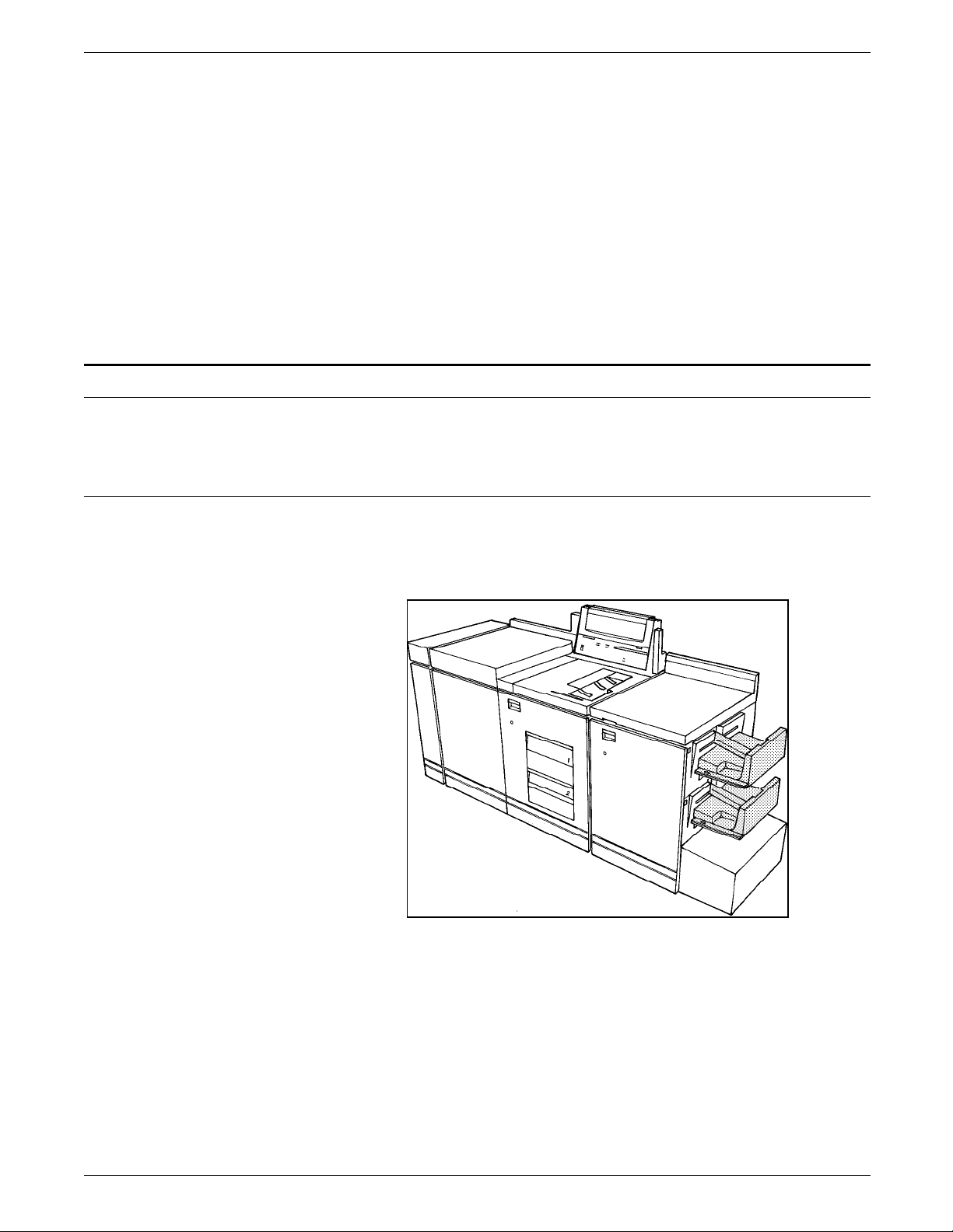
The 4050/4090/4450/4650 LPS consist of two base components
shown in figure 1-1. Your system may also have optional
components. This section helps you identify both the standard
and optional components in your system.
Figure 1-1. LPS base components
System controller
1 System controller
2 Printer
You interact with the system through the components of the
system controller shown in figure 1-2. The system controller also
contains the central processing unit and the system disks.
The configuration of the 4050 LPS system controller is slightly
different than the 4090/4650 system controller. When viewed
from the front, the terminal sits on top of the left side of the
4050 system controller, and on top of the right side of the
4090/4650 system controller. Figure 1-2 shows the 4090/4650
system controller.
Figure 1-2. System controller
1 Terminal
2 System controller panel
3 Diskette drive
1-4 XEROX 4050/4090/4450/4650 LPS OPERATOR GUIDE
Page 19
Optional components
Printer
OVERVIEW
The system controller panel shown in figure 1-3 contains
important controls for operating the printer.
Figure 1-3. System controller panel
There are several hardware options available for your LPS to
increase productivity. This section presents each option.
The printer has two stacker options: the dual stacker shown in
figure 1-4 and the stitcher/stacker shown in figure 1-5.
Figure 1-4. Printer with the dual stacker option
The dual stacker offers a choice of two separate output trays.
The stitcher/stacker offers the ability to staple sets.
XEROX 4050/4090/4450/4650 LPS OPERATOR GUIDE 1-5
Page 20

OVERVIEW
Figure 1-5. Printer with the stitcher/stacker option
Both stacker options also provide a sample tray for additional
limited output. The sample tray receives sample prints, rejected
pages, and transparencies.
The printer has two feed trays, shown in figure 1-5. Your LPS
may also have an optional high-capacity feeder, which adds two
feed trays to your system for a total of four feeder trays.
The printer control console shown in figure 1-6 displays
important messages, attention signals, and information about the
setup of your system. The printer control console also contains a
graphic mimic of the system for finding the location of paper
jams.
Figure 1-6. Printer control console
1. Message display
2. Graphic display
3. Information button
4. Print quantity display
5. Stop button
6. Continue button
7. Wire percentage indicator
8. Feeder tray indicators
9. Sample button
10. Power on/off switch
Message display: Shows printer status and simple operating and
maintenance instructions.
1-6 XEROX 4050/4090/4450/4650 LPS OPERATOR GUIDE
Page 21

OVERVIEW
Graphic display: Shows the area of the printer that requires
attention.
Information button: Press this button for information when i is
displayed on the message display. While i continues to display,
you can receive further information by pressing the button.
Print quantity display: Displays the number of prints
completed. Printer fault messages (such as L152) display here as
well.
Stop button: Pressing this button halts printing.
Continue button: Pressing this button resumes printing.
Wire Percentage indicator: Displays the amount of stitcher wire
remaining on the spool (stitcher/stacker output module
configurations only).
Feeder Tray indicators: Indicates the feeder trays selected and
the paper size loaded.
Sample button: Pressing this button causes the printer to
deliver a print sample to the sample tray of the next image
waiting in the queue.
Power on/off switch: This switch is for Service personnel only
for switching the printer module power off and on.
System controller options
This section provides an overview of the optional tape drives
your system may have.
9-track reel-to-reel magnetic tape drive
The 9-track magnetic tape drive can be added to the system
controller as an alternative to online operation. The drive uses 9track 1,600 bits per inch (bpi) phase encoded (PE) and 6,250 bpi
group code recording (GCR) encoded magnetic tapes.
Figure 1-7. 9-track reel-to-reel magnetic tape unit
9-track magnetic tape drive
XEROX 4050/4090/4450/4650 LPS OPERATOR GUIDE 1-7
Page 22

OVERVIEW
18-track cartridge tape system (180 CTS)
The 18-track cartridge tape system (180 CTS) offers alternative or
additional offline capability for inputting print and nonprint data
to the LPS. It reads and writes IBM- and ANSI-compatible 1/2inch/13 mm tape in the 18-track IBM 3480 data format.
Figure 1-8. 18-track cartridge tape system
1 Single transport configuration
2 Dual transport configuration
1/4-inch cartridge tape drive
The 1/4-inch cartridge (QIC) tape drive is also mounted within
the system controller cabinet. This unit provides an alternative
source for loading and backing up user files and loading or
unloading fonts to the system disks.
The capacity of the 1/4-inch cartridge tape drive is either 320 MB
or 525 MB, depending on the choice of DC6320 or DC6525 tape
cartridges. Both tapes are 1/4-inch cartridge ANSI compatible,
and they can be used interchangeably without hardware or
software recognition.
High-capacity feeder
The high-capacity feeder (HCF) is an option that can be added to
your printer. This option increases efficiency and allows you to
use specialized applications. The LPS base configuration includes
two feeder trays (feeder trays 1 and 2). The HCF option provides
two additional feeder trays (feeder trays 3 and 4), increasing the
feeder capacity by approximately 2,000 sheets.
1-8 XEROX 4050/4090/4450/4650 LPS OPERATOR GUIDE
Page 23

Figure 1-9. LPS with high-capacity feeder
1 HCF
2 Feeder tray 3
3 Feeder tray 4
Bypass transport
OVERVIEW
The bypass transport option enables third-party finishing
equipment to connect to your LPS. For more information about
the bypass transport, refer to the Xerox 4050/4090/4450/4650 LPS
Bypass Transport Instructions.
Figure 1-10. Printer with bypass transport
Print job sources
Your LPS can process print jobs from a variety of sources. Print
job sources can be divided into two main categories: online and
offline. Your LPS may have either one or both connection types.
The shared disk option on the 4090/4050 is realized through an
HPSCSI adapter which can be installed inside the system
controller. This adapter allows the printer to receive PostScript,
XEROX 4050/4090/4450/4650 LPS OPERATOR GUIDE 1-9
Page 24

OVERVIEW
Basic system functions
Function keys
PCL5, LCDS, and text format files from the front end adapter at
high speed.
To process online jobs through a network connection or through
a direct channel connection, your system is equipped with an
interface appropriate for the connection. The interface is
mounted inside the system controller cabinet. If you are unsure
of the interfaces installed in your system, consult your system
administrator.
Offline jobs are run from data stored on magnetic tape. You use
one or both of the tape drives discussed previously in this
chapter to process offline jobs with your LPS.
You use special function keys and command syntax to operate
the LPS.
<ALT> Activates the extended (alternate) characters in the green
keyboard. You must hold down the key.
<BACKSPACE> Deletes the character to the left of the cursor.
<CAP LOCK> Makes all characters you enter uppercase (all caps). This key
toggles on and off.
<CLEAR SCREEN> Clears all data from the screen and the display memory. The
cursor returns to column 1, line 1, in the upper-left corner of the
screen.
<CON> Resumes (continues) processing.
<CTRL><E> Deletes the character highlighted by the cursor.
<CTRL><X> Deletes the current line.
<CTRL><Z> Clears all data from the screen and the display memory. The
cursor returns to column 1, line 1, in the upper-left corner of the
screen.
<DELETE> Deletes the character to the left of the cursor.
<ENTER> Executes commands entered at the command line.
<HOME> Moves the cursor to the beginning of the current line.
<JOB STATUS> Displays status information about the print job. There can be a
delay of a few seconds before the status displays.
1-10 XEROX 4050/4090/4450/4650 LPS OPERATOR GUIDE
Page 25

OVERVIEW
<LEFT ARROW> Moves the cursor left one space.
<LINE DELETE> Deletes the current line.
<PRINTER STATUS> Displays printer status information. There can be a delay of a few
seconds before the status displays.
<RIGHT ARROW> Moves the cursor right one space.
<SAMPLE> Sends a sample of the next page to be printed to the sample
tray. Does not interrupt printing.
<SHIFT> Activates the symbols on the upper portion of the numeric keys,
such as punctuation and special characters.
<SPACE BAR> Inserts a space at the cursor position.
<STOP> Halts processing temporarily.
Commands
<TAB> Moves the cursor eight spaces to the right.
You enter commands at the command line of the system
controller. The LPS accepts your commands whenever the
following prompt displays:
READY FOR COMMANDS
For a command to be recognized by the system, you must do
the following:
1. Enter the command in the format specified by the system.
2. Press <ENTER> to execute.
If you make an error entering a command, the system displays
the following message:
OS2710 Invalid command. Re-enter.
1. Verify the command syntax:
— Keyword is correct
— All required parameters are included
— Parameters are correct
— Parameter values are valid
— Commas are in place for all parameters skipped.
2. Enter the command again.
Commands are not case-sensitive. You can enter them using
lowercase, uppercase, or a combination of the two.
The command syntax is made up of the following two elements:
• Keywords
• Parameters.
XEROX 4050/4090/4450/4650 LPS OPERATOR GUIDE 1-11
Page 26

OVERVIEW
Keywords
All commands begin with a keyword. This word sends a specific
instruction to the system (for example, SAMPLE).
You can enter keywords in any of the following ways:
• Full spelling (for example, SAMPLE)
• Abbreviation (for example, SAM)
• Three or more characters, up to the full command (for
example, REALLOC for REALLOCATE).
A few commands begin with more than one keyword (for
example, PQA STA). Exceptions to this are I, O, A (for INPUT,
OUTPUT, and ALL) and Q for QUEUE.
Other exceptions to keywords are words for CARTRIDGE and
TAPE. CAR and TAP are reserved and cannot be used as file
names.
Parameters
Most parameters are optional. You use them to refine
commands. For example, the “I” in STOP I specifies input
processing. Likewise, the “O” in STOP O specifies output
processing.
If you use more than one parameter, follow these guidelines:
• Separate each parameter with a comma (for example, PQA
CONTINUE,2,S).
• Do not include spaces around the commas.
• Enter parameters in the order specified for that command.
If you want to omit a parameter, you must enter a comma in its
place (for example, PQA CONTINUE,,S). The default value set
for the omitted parameter is then used.
For more information about commands, refer to the Xerox
4050/4090/4450/4650 LPS Command Reference.
1-12 XEROX 4050/4090/4450/4650 LPS OPERATOR GUIDE
Page 27

Powering up the LPS
2. Setting up the LPS
This chapter describes the procedures for powering up and
logging onto the system.
Follow this procedure to power up the system.
1. Select local or remote control of the system.
Press the Local button on the system controller panel to use
the internal power supply, or press the Remote button to use
a remote power supply. Contact your system administrator if
you are not sure what power supply to use.
2. Press the System Power On button.
Either the Local status indicator or the Remote status
indicator lights show the power supply you selected (refer to
step 1).
The Power On indicator lights.
A cursor appears on the system controller display for about
15 seconds while the system completes its initial diagnostic
tests, then READY $ appears on the display. There may be a
delay of up to 80 seconds before the $ appears.
3. Boot the operating system software.
Your system may be set up to boot automatically after
powering on. This control is set by the system administrator.
In this case, you do not need to boot the operating system
software.
If your system does not boot automatically, enter <B> at
the system controller keyboard.
XEROX 4050/4090/4450/4650 LPS OPERATOR GUIDE 2-1
Page 28

SETTING UP THE LPS
When the booting process is complete, the system controller
displays the following messages:
XEROX 4090
LASER PRINTING SYSTEM
Version V4 Revision X.X
Copyright 1991, 1992, 1993,1994 Xerox Corporation. All rights reserved.
Disk ID = system name JAN 3, 1994 15:06:16
When initialization is complete, the system displays the ready
message:
OS1000 READY FOR COMMANDS
4. Log on to the system.
Logging on to security level 1 is automatic. This security
level is usually appropriate for an operator. However, if you
want to enter the SETTIME command, you must log on to
security level 2.
To log on to level 2, enter the LOGON command:
LOGON 2 [,password]
Your system administrator must provide you with the
password for security level 2. For more information about
logging on, refer to the Xerox 4050/4090/4450/4650 LPS
Command Reference.
After powering on, allow four to seven minutes for the
printer to warm up. When the printer is ready, you hear a
tone, and the system displays the following message on the
printer control console:
READY--JOB START WILL BE DELAYED 20-40 SECONDS FOR PRINT
QUALITY ADJUSTMENT
2-2 XEROX 4050/4090/4450/4650 LPS OPERATOR GUIDE
Page 29

3. Setting up print job sources
You can transmit print jobs to the system from one of four
sources:
• From a magnetic tape. This is known as an offline job
source. The system supports 18-track cartridge tape, 9-track
(1600/6250 bpi) 1/2-inch and 1/4-inch cartridge tape, and 9track magnetic tape formats to print offline jobs:
— Mount the tape on the appropriate tape drive. Refer to
the “9-track magnetic tapes” or “18-track cartridge tapes”
section in this chapter.
— Establish communication between that tape drive and the
controller. Refer to the “Receiving offline jobs” section
in this chapter.
• From a channel-attached host computer. This is known as an
online job source. Refer to the “Communicating with the
channel-attached host” section in this chapter.
• From a network connection through the host interface
processor. This is also an online job source. Refer to the
“Communicating through the host interface processor”
section in this chapter.
9-track magnetic tapes
• From a front end host (such as a Sun SPARCstation 10) and
Entire® APPLICATION software using the shared disk option
to print files.
Improper handling of 9-track tapes can cause damage to tapes
and to tape drives, which can result in unreadable data. Observe
the following guidelines when handling 9-track tapes:
• Do not allow dust, dirt, or smoke to come in contact with
the tapes, tape storage area, or tape drives.
• Do not touch the tape beyond the first few feet on the reel.
• Do not place tapes near electric motors or other devices that
generate electromagnetic energy.
• Do not pull on the tape at the end of a reel. Wind tape off
the supply reel by turning the reel at the hub.
• Make sure that the components of a tape drive are clean and
dry before mounting the tape.
• Store tapes vertically in racks in a clean, climate-controlled
environment. If the temperature or humidity of the tape
storage environment differs from the printer environment,
condition tapes for 24 hours in the printer environment
before using them.
XEROX 4050/4090/4450/4650 LPS OPERATOR GUIDE 3-1
Page 30

SETTING UP PRINT JOB SOURCES
Write protection of 9-track magnetic tapes
Write protected 9-track magnetic tapes have a removable writeenable ring that fits into the inside of the reel, as shown in figure
3-1. Removing the write-enable ring prevents the system from
writing data onto the tape. This protects the data on the tape
from accidental erasure.
Figure 3-1. 9-track magnetic tape write protection
In most cases, you do not need to write data to a tape when
running print jobs, so it is not necessary to have the write-enable
ring installed.
18-track cartridge tapes
Improper handling of cartridge tapes can cause damage to tapes
and to tape drives, which can result in unreadable data. Observe
the following guidelines when handling cartridge tapes:
• Inspect each cartridge for obvious damage before inserting it
into the cartridge tape drive.
• Always remove cartridges from the tape drive before
powering off the drive.
• Store cartridges vertically in racks in a clean, climatecontrolled environment. If the temperature or humidity of
the tape storage environment differs from the printer
environment, condition the cartridges for 24 hours in the
printer environment before using them.
• Never attempt to open the cartridge, remove the tape from
the cartridge, or force open the feed slot door.
• Do not expose the cartridges to extreme heat, humidity, or
direct sunlight.
• Do not place tapes near electric motors or other devices that
generate electromagnetic energy.
• Do not attempt to clean a cartridge with anything other than
a dry, lint-free cloth.
• If the leader block comes off a cartridge tape, repair the
cartridge using a leader block repair kit before loading it.
• Do not attempt to insert a cartridge if its label is peeling off.
Peel the old label completely off and replace it with another
label.
3-2 XEROX 4050/4090/4450/4650 LPS OPERATOR GUIDE
Page 31

SETTING UP PRINT JOB SOURCES
• Do not write on a tape cartridge label while it is on the
cartridge. If you want to change a label, write a new label,
remove the old label, and replace it with the new label.
Write protection of cartridge tapes
An 18-track cartridge tape has a thumbwheel on the side of the
cartridge for write protection, as shown in figure 3-2. Write
protection prevents the system from writing data onto the tape.
This protects the data on the tape from accidental erasure.
Figure 3-2. 18-track cartridge tape write protection
To enable write protection (prevent data from being erased), turn
the thumbwheel so that the white dot is showing in the window.
Loading an 18-track cartridge tape
To disable write protection (allow data to be written to the tape),
turn the thumbwheel so that the white dot is not showing in the
window.
In most cases, you do not need to write data to a tape when
running print jobs, so it is safer to enable write protection before
loading tapes.
Follow these steps to load a 18-track cartridge tape:
1. Inspect the cartridge for visible damage.
For more specific information on checking for signs of
damage, refer to the guideline for handling tapes at the
beginning of this section.
CAUTION: Loading a damaged tape can damage the tape
drive and result in data loss.
XEROX 4050/4090/4450/4650 LPS OPERATOR GUIDE 3-3
Page 32

SETTING UP PRINT JOB SOURCES
2. Hold the cartridge with the smooth side on top and the
leader block toward the drive.
3. Insert the cartridge into the entry slot and slide it all the way
into the drive opening until it stops.
CAUTION: When you insert a cartridge, never force it.
Loading and unloading a floppy diskette from the system controller
Follow these steps to load and unload a floppy diskette:
1. Before inserting a floppy diskette into the floppy diskette
drive, make sure the lever is in the open (horizontal)
position. Insert the floppy diskette, label side up, until the
jacket is solidly against the stops. Move the lever clockwise
to the closed (vertical) position.
1 Lever
2 Floppy diskette drive
3 Floppy diskette
3-4 XEROX 4050/4090/4450/4650 LPS OPERATOR GUIDE
Page 33

2. To remove the floppy diskette from the diskette drive, move
the lever counterclockwise to the open position. The floppy
diskette should pop out slightly. Place the diskette in its
protective envelope.
Using the 9-track magnetic tape drive
Another optional 9-track magnetic tape drive resides in a cabinet
on top of the controller. Figure 3-3 shows the basic parts of this
component.
Figure 3-3. 9-track magnetic tape drive components
SETTING UP PRINT JOB SOURCES
1 Control panel
At the upper-left corner are the touch-sensitive switches that
direct the magnetic tape drive. Some tape drive commands
may also be keyed in at the keyboard. Each of these
switches is described in the “Control panel switches” section.
2 Power switch
The main power switch (circuit breaker) is at the upper-right
corner of the tape deck. In the OFF position (the 0 side
pressed), the input AC voltage is removed from the tape
drive power supply. In the ON position (the 1 side pressed),
the transport is powered on by reapplying the input AC
voltage.
3 File reel
The file reel (supply reel) is mounted onto the upper hub.
The tape may be either a job tape or a scratch tape for
diagnostics.
3a Hub latch
3b Hub latch release button
4 Fixed reel
The fixed reel is the one permanently attached to the tape
transport. Sometimes known as the machine reel, it
functions as a take-up reel for the tape supply.
XEROX 4050/4090/4450/4650 LPS OPERATOR GUIDE 3-5
Page 34

SETTING UP PRINT JOB SOURCES
5a and 5b Air bearings
Two air bearing sensor assemblies (upper [b] and lower [a] air
bearings) are used to guide the tape across the magnetic
head on an air cushion and to measure air pressure
reflection. The pressure signal is processed by the control
system, which maintains constant tape velocity and air
pressure by changing the reel motor speed whenever
appropriate.
6 Magnetic head assembly
This assembly consists of a read/write head and an erase
head. The dual-gap read/write head unit is designed to
perform the read/write functions in a 9-track format. It allows
a write-to-tape operation, a read-only operation, or a readafter-write operation. During a write operation, a full-width
erase head erases the tape while it moves forward before the
tape passes over the write head.
7 Erase head
8 BOT/EOT assembly
Located next to the magnetic head assembly, this assembly
optically detects the beginning-of-tape (BOT) and the end-oftape (EOT) markets. Photosensors detect light reflected from
the BOT and EOT markers on the tape so that the tape drive
can recognize starting and stopping areas.
Control panel switches
9 Tape cleaner
The cleaner consists of two blades and a vacuum port to strip
unwanted particles off the tape surface. It is designed so
that the first blade cleans the tape in the forward direction
and the second cleans it in the reverse direction. The
vacuum port removes the unwanted particles from that area.
10 File protect sensor (not shown)
This sensor consists of a reflective ring around the file
(supply) hub and a photosensor next to it that are used to
detect the presence or absence of the write-enable ring on
the file reel.
11 Cover interlock (not shown)
There is an interlock associated with the door latch as a
safety device. The tape unit can be operated only when the
door is closed.
Two types of functions are controlled by the switches on the
control panel: operator and maintenance. Switches to the left
of the two-digit LED display are the operator functions, and
switches to the right of the display are for maintenance
functions. When the magnetic tape drive is online to the printer,
maintenance functions do not work. Figure 3-4 shows the
control panel switches.
3-6 XEROX 4050/4090/4450/4650 LPS OPERATOR GUIDE
Page 35

SETTING UP PRINT JOB SOURCES
Figure 3-4 Control panel switches
• Logic Off switch and indicator
If pressed while the magnetic tape drive is powered on,
logical power (the DC power to the circuit boards) is
removed. The indicator light comes on to signal a standby
power condition.
• Logic On switch and indicator
If pressed while the circuit breaker is on and the magnetic
tape drive is in a standby power condition, the logical power
(the DC power to the circuit boards) is returned to the
magnetic tape drive.
• File protect indicator
The file protect indicator is lit when the write-enable ring in
the magnetic tape reel is absent. When this indicator is on,
data cannot be written to or erased from the tape.
• BOT indicator
The BOT indicator is lit when the tape is positioned at the
BOT marker (a reflective band on the tape indicating the
beginning of data).
• Load/Rewind switch
If the magnetic tape drive is powered on and a tape
threaded, press the Load/Rewind switch to initiate tape
loading. If the tape has already been loaded and threaded,
press the Reset switch and then the Load/Rewind switch to
rewind the tape to the BOT marker.
Note: Following the load or rewind operation, the unit
automatically sets to 25 inches per second (ips) start/stop
mode and positions the tape accordingly. The rewind rate is
75 ips.
XEROX 4050/4090/4450/4650 LPS OPERATOR GUIDE 3-7
Page 36

SETTING UP PRINT JOB SOURCES
• Unload switch
If a tape is loaded, press the Reset switch and then the
Unload switch to unload the tape completely from the fixed
reel and the tape path. If a tape is threaded but not loaded,
pressing the Unload switch causes the tape to slowly unload
to the supply reel.
• On Line switch and indicator
If a tape is loaded, press the On Line switch to place the
magnetic tape drive online to the system controller. The
indicator lights whenever the magnetic tape drive is online.
The magnetic tape drive must be online to the printer to
receive data from magnetic tape or to respond to entered
tape commands.
• Reset switch and indicator
The Reset indicator is lit whenever a magnetic tape drive
error condition occurs or at the completion of a diagnostic
test. Press the Reset switch to take the magnetic tape drive
offline from the printer. Tape motion stops, and error status
is cleared.
You must also press the Reset switch, taking the unit offline
to use other touch-sensitive switches (such as the Unload
and Rewind). Only entered tape control commands are
accepted when the magnetic tape unit is online to the
printer.
Note: Some control faults require a power-off/power-on
sequence to clear. Refer to the Xerox 4850/4890 HighLight
Color LPS Message Guide for additional information.
• High-density indicator
The high-density indicator is lit whenever the magnetic tape
drive is operating in the group code recording (GCR) mode.
GCR refers to the specific density of data as it is recorded on
the tape, which is measured in bits per inch (bpi). The tape
drive operates in 1600 bpi Phase Encoded (PE) or 6250 bpi
(GCR) modes. The default for writing is 1600 bpi. There is
no default for reading because the system checks the speed
and reads it accordingly.
• Two-digit LED display
When in offline diagnostic test mode, the diagnostic test
numbers and results of the microdiagnostic or exerciser
routines display. When the reset indicator lights, a diagnostic
fault code or an online operational failure code displays.
• Diagnostics indicator
The diagnostics indicator is lit when the magnetic tape drive
is in diagnostic test mode.
• Test switch
When the magnetic tape drive is not online, press the test
switch to enter diagnostic test mode. If the magnetic tape
drive is online, there is no response because the
maintenance/diagnostic functions do not operate in the
online mode.
3-8 XEROX 4050/4090/4450/4650 LPS OPERATOR GUIDE
Page 37

SETTING UP PRINT JOB SOURCES
• Step switch
When the magnetic tape drive is in diagnostic test mode,
press the Step switch to advance diagnostic test numbers. If
the magnetic tape drive is online, there is no response
because the maintenance and diagnostic functions do not
operate in the online mode.
• Execute switch
When the magnetic tape drive is in diagnostic test mode,
press the Execute switch to start the diagnostic test indicated
by the numbers in the two-digit display window. If the
magnetic tape drive is online.
• CE switch
This switch aids the service representative with special
diagnostics. If the magnetic tape drive is online, there is no
response because the maintenance/diagnostic functions do
not operate in the online mode.
CAUTION: This switch is used for higher-level diagnostics,
which only a service representative can interpret. Improper
use could cause incorrect status codes and responses, or
information on the magnetic tape could be destroyed.
Powering on the tape drive
Loading a 9-track tape
Follow these steps to power on the tape drive:
1. Open the tape transport door. The power switch is located
in the upper-right corner of the tape deck.
2. Press down the side of the Power switch marked 1.
Follow these steps to load a 9-track tape:
1. Press the large button in the center of the supply hub (the
latch release) to unlock the hub. Place the job tape reel
firmly on the hub, with the read/write ring side (if applicable)
facing away from you.
XEROX 4050/4090/4450/4650 LPS OPERATOR GUIDE 3-9
Page 38

SETTING UP PRINT JOB SOURCES
2. Press the file reel latch until it clicks, to relatch the hub and
lock the reel in place.
3. Carefully unwind about 3 to 4 feet (1 meter) of tape from the
reel. Loosely drape it over the top of the upper air bearing.
Leave some slack between the reel and the air bearing.
CAUTION: When handling the tape, try to touch only the
edges and never handle the tape beyond the BOT reflective
strip. You could damage or destroy data beyond that point.
4. Insert the tape sideways into the slot between the head
covers. Gently guide it beneath the lower air bearing and
drape it over the top of the fixed reel.
CAUTION: Make sure that the tape is correctly positioned
over all tape path components or tape damage may occur.
3-10 XEROX 4050/4090/4450/4650 LPS OPERATOR GUIDE
Page 39

SETTING UP PRINT JOB SOURCES
5. Insert your index finger through one of the holes in the fixed
reel to hold the leading edge of the tape firmly against the
center of the reel. Wind the reel clockwise until the tape
laps over enough of itself to be secured to the reel.
Placing a tape online to the LPS
6. Once the tape is secured, continue to wind the reel in the
clockwise direction to gently take up the remaining slack in
the tape path. The tape is now threaded but not loaded.
7. Close the door to load the tape.
Note: Until you close the door, the cover interlock in its
electrical sensing system continues to disable the command
switches on the operator control panel.
8. Press the Load Rewind switch on the operator control panel.
The BOT indicator lights as soon as the beginning of the tape
is found.
Note: If the tape drive cannot find the BOT within 25 feet
(7.62 meters) in the forward direction, it reverses to search
for it. If the tape drive cannot find the BOT in either
direction, it stops, and an error status code appears in the
two-digit LED display on the operator control panel.
You must now place the tape drive online to the LPS.
Follow these steps to place a tape online:
1. Press the On Line switch to place the unit online to the
system controller. The switch may be pressed while the
loading operation is in progress. When the online indicator
lights, loading is complete. The tape is now threaded and
loaded. You are ready to start jobs.
Note: If the online indicator does not light when you press
the switch, refer to the “9-track magnetic tape drive on the
controller cabinet problems” section of the “Solving
problems” chapter.
2. If your LPS is connected to both a 9-track magnetic tape
drive and an 18-track cartridge tape system, you must tell the
printing system which tape drive you intend to use. You do
XEROX 4050/4090/4450/4650 LPS OPERATOR GUIDE 3-11
Page 40

SETTING UP PRINT JOB SOURCES
Taking a tape offline from the LPS
Unloading a tape
this by entering MTU 0 or MTU 1. The unit number is
assigned to the tape drive at installation by a service
representative. Check with your service representative or
your system administrator if you are unsure of the number
assigned to your 9-track magnetic tape drive.
CAUTION: To avoid writing on an unprotected tape by mistake,
always enter your tape drive choice before beginning a job.
Press the Reset switch on the control panel to place the unit
offline to the system controller.
A tape may be unloaded either manually or automatically (by a
keyboard command).
Unloading a tape manually
1. Press the Reset switch on the control panel to take the
transport offline from the system controller.
2. Press the Unload switch. The tape rewinds onto the file reel
until the end clears the fixed reel and the tape path.
Tape unloading is performed at low speed. If there is a
considerable amount of tape on the fixed reel and you want
to unload it more quickly, first press the Load Rewind switch
and then the Unload switch.
Note: Pressing only the Load Rewind switch causes the tape
to rewind at the faster rate, but it stops at the BOT marker
instead of completely clearing the tape path.
3. Open the door and press the large button in the center of
the supply hub to unlatch it and release the tape reel.
Remove the reel.
4. Close the door to prevent dust accumulation.
Unloading a tape by using the keyboard commands
When the tape drive is online to the system controller, you can
perform the unload operation through the keyboard. As a safety
precaution, the system ignores the TAPE UNLOAD command
while a job is printing.
1. Enter TAPE UNLOAD. The tape rewinds completely back
onto the supply reel.
2. Remove the file reel by following steps 3 and 4 of the
“Unloading a tape manually” procedure, above.
Powering off the tape drive
Once you have unloaded and removed the tape from the
transport, press down the side of the Power switch marked 0.
(The Power switch is in the upper-right corner of the tape deck.)
3-12 XEROX 4050/4090/4450/4650 LPS OPERATOR GUIDE
Page 41

Using the 18-track 180 Cartridge Tape System
The 18-track 180 Cartridge Tape System (CTS) is an alternative to
the 9-track magnetic tape drive. It also provides additional
offline capability. It reads and writes to IBM- and ANSIcompatible 1/2-inch tape in the 18-track IBM 3480 data format.
Like the 9-track magnetic tape drive, the CTS can be used as a
source for the loading and backing up of non-printing files (such
as forms and fonts) to and from the system disks, as well as
providing an input source for print jobs.
The 18-track CTS uses standard 1/2-inch chromium dioxide
cartridge tapes. Tape loading is fully automatic as soon as the
tape is inserted into the feed slot and the door is closed. The
18-track CTS may be ordered with one or two tape transports. If
only one is ordered initially, a second may be added at a later
date. Figure 3-5 shows both the single and dual transport CTS.
Figure 3-5. 18-track CTS
SETTING UP PRINT JOB SOURCES
XEROX 4050/4090/4450/4650 LPS OPERATOR GUIDE 3-13
Page 42

SETTING UP PRINT JOB SOURCES
Locating CTS components
Figure 3-6 shows the components of the CTS.
Figure 3-6. Components of the CTS
1 Tape transport
The tape transport is where the tape is processed (read/write
functions) and includes the status and control panel. You
can have one or two tape transports in your cartridge.
2 Power control panel
A description of the switches on the control panel, shown in
figure 3-7, is provided below.
Figure 3-7. Control panel switches
1 Emergency Power Off (EPO) switch
Pressing the EPO switch starts an uncontrolled power down
that can result in lost data and system problems. Once you
press the EPO switch, you must place a service call, because
only a service representative can restore power to the
system.
3-14 XEROX 4050/4090/4450/4650 LPS OPERATOR GUIDE
Page 43

SETTING UP PRINT JOB SOURCES
2 Power on/off switch
Under normal circumstances, the power switch is used to
power the tape system on and off. When you put the power
switch in the off position, you start an orderly power-down
process. When a situation exists that threatens the safety of
an individual or the equipment, you can press the EPO
switch. The green indicator on the upper half of the power
switch lights when the tape drive is powered on.
3 Feed slot
The feed slot is where cartridges are inserted for loading. An
elevator behind it lowers cartridges to their operating
position and raises them again to the feed slot for you to
remove when completed. The door must be closed before
the elevator can work. The Unload button is used to open
this door whenever the transport is neither processing a tape
nor in a ready mode (ready indicator light is not lit). The
tape drive stays cleaner when the feed slot door is kept
closed, whether or not there is a tape loaded.
4 Status and control panel
There is a status and control panel for each tape transport.
Located above the transport, it contains the message
window, three LED message lights, a ready indicator light,
and three tape drive control buttons.
Status and control panel components
Figure 3-8 shows the status and control panel.
Figure 3-8. Status and control panel components
1 Ready indicator light
This indicator lights when you press the Ready button, and
the transport is ready to read and write tapes. While this
light is on, the tape drive ignores the Rewind and Unload
buttons if they are pressed.
2 Ready button
Pressing the Ready button enables the read/write functions of
the tape drive. Pressing it again disables the read/write
functions. If the cartridge tape system is the only magnetic
tape device connected to your LPS, pressing the Ready
button on puts the tape drive online. Pressing the Ready
button again takes it offline. The CTS does not allow you to
use the Unload or Rewind buttons while it is in the ready
XEROX 4050/4090/4450/4650 LPS OPERATOR GUIDE 3-15
Page 44

SETTING UP PRINT JOB SOURCES
mode. While the tape drive is ready and online to the LPS,
you must enter the TAPE UNLOAD and REWIND commands.
3 Unload button
If a tape is loaded, pressing the Unload button causes the
tape drive to completely rewind the tape into the cartridge
and deliver the cartridge back to the feed slot for removal.
The tape drive ignores the Unload button as long as the drive
is in the ready mode (when the ready light is on).
Alternatively, you can enter the TAPE UNLOAD command
when the tape drive is online to the LPS.
Note: If the feed slot door is closed but no tape is in the
drive, the door opens when you press the Unload button,
regardless of whether or not the ready light is on.
4 Rewind button
If the tape system is powered on and a cartridge is loaded,
pressing the Rewind button rewinds the tape to the BOT
marker. The tape drive ignores this button while it is in the
ready condition (when the ready light is on). Alternatively,
you can enter the TAPE REWIND command when the tape
drive is online to the system.
5 Message window
The 10-character message window is where the transport
displays status messages. Some messages contain 4-digit
status codes that refer to common problems. Others explain
what the tape drive is currently doing; for example,
unloading, rewinding, or cleaning. Figure 3-9 shows what
you see while a cleaning tape is being run.
Figure 3-9. Message window
6 Offline light
When this yellow rectangle is lit and you can see the word
OFFLINE, the transport is offline from the LPS.
7 Operator light
When this red rectangle is lit and you can see the word
OPERATOR, the transport needs operator assistance. A
problem exists that must be handled before the transport can
continue. A message appears in the message window
indicating what to do or providing you with a status message
for your service representative.
3-16 XEROX 4050/4090/4450/4650 LPS OPERATOR GUIDE
Page 45

Powering on the 180 CTS
SETTING UP PRINT JOB SOURCES
8 Select light
When this green rectangle is lit and you can see the word
SELECT, this transport is selected for operation. Once it is
operating, the light blinks on and off as it is receiving
instructions from the controller.
Follow these steps to power on the 180 CTS:
1. Locate the power control panel on the lower-left side of the
font door.
2. Press the Power switch to the ON position by pressing down
on the side marked 1.
The CTS goes through a series of self-tests and initialization.
While it is going through this process, the following message
displays:
*SELFTEST*
Then the following messages display:
DOWNLOAD O, TESTING O, TEST DONE, FUNCTIONAL.
Loading a tape
Note: In the “download” and “testing” messages, the
number may be 0, 1, 2, or 3, depending on how many tape
transports you have. These are the numbers assigned to
each transport by the service representative when your
system is installed. The numbers are used only by the service
representative.
3. When the tape system has completed its initialization or boot
process, a single asterisk (*) appears in the message window.
The transport is now ready for you to load a tape and place
the CTS online to your LPS.
Follow these steps to load a tape:
1. As soon as the asterisk appears in the message window, you
can load a tape. Carefully insert the cartridge into the feed
slot, with the label side up and the latch in the right corner
(away from you).
When you insert the cartridge, the red operator light comes
on, and the following message displays:
XEROX 4050/4090/4450/4650 LPS OPERATOR GUIDE 3-17
Page 46

SETTING UP PRINT JOB SOURCES
CLOSE DOOR
2. Close the feed slot door by gently pulling down the handle
until the door latches shut.
The operator light goes off, and the following message
displays if the file is unprotected:
READY U
The following message displays if the file is protected:
READY F
Loading a 1/4-inch cartridge tape
Placing a tape online to the LPS
Follow these steps to load a 1/4-inch cartridge tape:
1. Locate the 1/4-inch cartridge tape drive, mounted in the
system controller cabinet next to the floppy disk drive.
2. Press the cover release button.
The tape drive door partially opens.
3. Manually open the door completely.
4. Insert the cartridge (label facing to the left) into the feed slot.
5. Close the tape drive door.
The tape loads automatically.
If the tape has loaded properly, the LED indicator light is
green.
If the LED indicator light is flashing red, the tape has not
loaded properly. Refer to the “Solving problems” chapter, or
see your system administrator.
Follow these steps to place a tape online:
1. If the following message displays, press the Ready button to
enable the read/write mode:
NT READY U or NT READY F
The ready indicator light comes on, and the nt ready
message changes to ready.
If you have only the cartridge tape system for your system,
you are now ready to print jobs. Your system is automatically
online to the LPS as long as the ready indicator light is on.
3-18 XEROX 4050/4090/4450/4650 LPS OPERATOR GUIDE
Page 47

Unloading a tape
SETTING UP PRINT JOB SOURCES
2. If your LPS is connected to both a 9-track magnetic tape
drive and an 18-track cartridge tape system, you must specify
the tape drive. You do this by entering MTU 0 or MTU 1.
The 0 and 1 are assigned to each tape drive at installation by
a service representative. Check with your service
representative or your system administrator if you are not
sure if 0 or 1 was assigned to your 18-track CTS.
Note: This is not necessarily the same number you see in
the message display window of each cartridge tape transport
when the cartridge tape system is powered on and goes
through its testing and downloading routines.
CAUTION: To avoid writing on an unprotected tape by mistake,
always enter your tape drive choice before beginning a job.
Now that your tape drive is loaded and online to the LPS, you
are ready to print jobs.
Follow these steps to unload a tape:
1. When the EOT is reached or a job is completed, the
transport rewinds and unloads the cartridge. The feed slot
door opens automatically. When it does, carefully remove
the cartridge.
To remove a tape at any other time, first press the Ready
button to take the transport out of the read/write mode. The
ready indicator light must be off.
2. Press the Unload button on the transport status and control
panel.
If the tape needs to be rewound before unloading, the
following message displays during that process:
REWINDING
The following message displays for the few seconds required
to return the cartridge to the feed slot and open the door:
UNLOADING
Note: To use the TAPE UNLOAD command from the
keyboard, the tape drive must be online to the LPS.
3. When the feed slot door opens and the cartridge is
unloaded, remove the tape cartridge carefully.
XEROX 4050/4090/4450/4650 LPS OPERATOR GUIDE 3-19
Page 48

SETTING UP PRINT JOB SOURCES
Taking a tape offline from the LPS
Powering off the CTS
Receiving offline jobs
Any time the ready indicator light is off, the CTS is offline from
the LPS.
Press the Ready button once so that the ready indicator light
goes off. The following message displays if a cartridge tape is
still in the drive:
NT READY U or NT READY F
If there is no tape in the drive, a single asterisk (*) appears.
Once you have unloaded and removed the tape cartridge from
the transport, press down the side of the power switch marked
0.
Before printing offline jobs, you must identify the tape drive
where you mounted the tape containing the print job.
If your system is equipped to process offline jobs, you may have
a 9-track magnetic tape drive, a 180 CTS, or your system may
have both. These are your print job sources for offline jobs.
Your system may also be equipped with a 1/4-inch cartridge tape
drive. This is not a source for print jobs.
The system recognizes two keywords for specifying the tape
drive where the job tape is mounted: TAPE and CARTRIDGE.
You must identify the physical tape drive assigned to each of
these keywords. You identify the device using the SUB DEVICE
command. For example, if you are using a cartridge you would
enter a substitute device command, such as SUB DEV SFCTS FOR
TAPE.
The TAPE keyword applies to 9-track magnetic tape drives. Your
system has only one option for a 9-track magnetic tape drive, so
you do not need to identify the physical device for this keyword.
If an open reel tape drive is installed in your system, the TAPE
keyword identifies this device by default.
The CARTRIDGE keyword applies to cartridge tape drives. Your
system has two options for a cartridge tape drive: the 18-track
180 CTS (1/2-inch cartridge tape drive), and the 1/4-inch cartridge
tape drive. The 1/4-inch cartridge tape drive is not a source for
print jobs, but it may be identified for copying and backing up
files.
• If only one of these tape drive options is installed in your
system, you do not need to identify the physical device for
the CARTRIDGE keyword.
• If both cartridge tape drives are installed in your system, you
must identify the drive using the SUB DEVICE command.
3-20 XEROX 4050/4090/4450/4650 LPS OPERATOR GUIDE
Page 49

To identify the 18-track 1/2-inch cartridge tape drive with the
CARTRIDGE keyword, enter the following command:
SUB DEV SFCTS FOR CAR
To identify the 9-track cartridge tape drive and the 1/4-inch
cartridge tape drive with the CARTRIDGE keyword, enter the
following command:
SUB DEV SCTS FOR CAR
The device specification remains in effect until you enter a new
SUB DEVICE command. For more information about the SUB
DEVICE command, refer to the Xerox 4850/4890 HighLight Color
LPS Command Reference.
Communicating with the channel-attached host
A system that is channel attached to a host can receive data from
the host in online mode. Before data can be sent to the printer,
both the printer operator and the host operator must issue
commands to place the LPS online to the host.
All system operations and maintenance tasks can be performed
while the printing system is online. However, you may be asked
to take the system offline for service or other purposes, and to
bring it back online when ready to resume operation.
SETTING UP PRINT JOB SOURCES
Placing the LPS online
Taking the LPS offline
Follow these steps to place the LPS online:
1. Enter ONLINE.
The system responds by displaying:
OS0030 System is “ON-LINE”
OS1000 READY FOR COMMANDS
2. Enter START and begin normal job processing.
Until a START command is entered, the LPS is in an online
but not ready state, and the host does not transmit any data.
3. Request the host operator to vary the system online.
For more information on starting print jobs, refer to the
“Printing jobs” chapter.
Follow these steps to take the system offline:
1. Request the host operator to drain or purge the output from
the host to the LPS, then vary the system offline at the host.
2. Press <JOBS STATUS> to determine if the system is idle.
3. If the job queue is empty, enter OFFLINE, or ENDJOB
followed by OFFLINE.
Entering the ENDJOB command prints any pages remaining
in the print file. Then press <JOBS STATUS> again to verify
that the queue is empty. Enter the OFFLINE command.
XEROX 4050/4090/4450/4650 LPS OPERATOR GUIDE 3-21
Page 50

SETTING UP PRINT JOB SOURCES
4. Enter CONTINUE I or press <CON>. The following
message displays:
OS0040 System is “OFF-LINE”
Communicating through the Shared Disk Interface processor
Follow these steps to place the Shared Disk Interface (SDI) online
to the system:
1. Enter SDI to put SDI online and start it.
2. Send the jobs from the front end.
For more information, refer to the Xerox Shared Disk Option
Operator Guide.
Communicating through the host interface processor
The system can communicate with hosts that are not channelattached, in a range of communication environments, or with
other networked devices through the host interface processor
(HIP) software. All you have to know is the interface or mode
you use to communicate with the host or network. A brief
description of each mode is provided in the “Selecting a
communication mode” section later in this chapter. For more
information, refer to the Xerox 4050/4090/4450/4650 LPS
Command Reference.
Starting HIP
Selecting a communication mode
To start HIP, enter HIP.
This is an abbreviated way of entering the commands HIP
ONLINE and HIP START, and is the routine method of starting
the HIP task. After you enter the HIP command, the following
messages display:
HP0010 HOST INTERFACE PROCESSOR loaded
OS1000 READY FOR COMMANDS 15:52:21
HP1210 HOST ONLINE, ACCEPTING ALL JOBS
OS1000 READY FOR COMMANDS 15:52:23.
If the host is not online and not responding, the following
message displays every 15 seconds until the host comes online
or HIP is terminated.
HP1240 HOST NOT RESPONDING
For a complete explanation of all the HIP options available, refer
to the Xerox 4050/4090/4450/4650 LPS Command Reference.
Enter HIP HOST, specifying the communication mode.
HIP HOST {871|DMR|XNS|XPF|XPS}
3-22 XEROX 4050/4090/4450/4650 LPS OPERATOR GUIDE
Page 51

Changing hosts
SETTING UP PRINT JOB SOURCES
When you enter this command, you can specify one of the
following:
• 871—Identifies a host in an SNA/SDLC or BSC environment.
• DMR—Identifies a VAX/VMS host in a DDCMP environment.
• XNS—Identifies a network environment.
• XPF—Identifies an IBM host in an MVS/XA or an MVS/ESA
environment.
• XPS—Identifies Xerox Print Services (XPS) Manager as the
printer front end to other hosts. (This option is available in
XDDI only.)
If your LPS interfaces with only one host, then HIP automatically
performs this function each time it is loaded.
Follow these steps to change hosts:
1. Make sure HIP is loaded and offline.
Refer to the “Starting HIP” section above and “Taking HIP
offline” section later in this chapter, if you are uncertain how
to perform either task.
Placing HIP online
2. Enter HIP HOST, as described in the previous section, to
select a new mode.
If HIP is not offline or if the system is not idle, the command
is rejected, and one or more of the following messages
display:
HP2020 SELECTED HOST NOT PRESENT ON SYSTEM
HP2400 HIP INTERFACE MUST BE OFFLINE. ENTER HIP OFFLINE
HP7100 CANNOT CHANGE HOST WHILE JOBS ARE PENDING OR ACTIVE
For the system to receive files, you must place the interface
online. Enter HIP ONLINE [ALL]:
The ALL parameter specifies that both print and nonprint files are
accepted; otherwise, only print files are accepted. As print jobs
are received, they are entered into the HIP job queue before
being entered into the Queue Manager queue.
One of the following messages displays:
HP1210 HOST ONLINE. Accepting ALL jobs.
HP1220 HOST ONLINE. Accepting print jobs only.
HP2010 No HOST selected.
HP2030 ALL not allowed at current LOGON level.
HP0200 Failed to go ONLINE.
ONLINE ALL is accepted in logon level 2 and above for all hosts
except for XNS hosts. HIP is always in ONLINE ALL mode for
XNS hosts.
If the selected host is not online and responding, the following
message displays every 30 seconds until the host comes online
or the online request is terminated using HIP OFFLINE command:
HP1240 HOST not responding.
XEROX 4050/4090/4450/4650 LPS OPERATOR GUIDE 3-23
Page 52

SETTING UP PRINT JOB SOURCES
Taking HIP offline
Note: You may find that HIP is stopped. In that case, enter HIP
STA or HIP START. The system responds with
COMMANDS.
OS1000 READY FOR
To take HIP offline and stop it from accepting files from the host,
enter HIP OFFLINE.
The system response is delayed to the end of the current file if a
file is being transmitted. The following messages display:
HP1200 OFFLINE pending End Of Transmission.
HP1207 OFFLINE pending end of current active XNS session.
HP1230 HOST OFFLINE.
The following are reasons the message HP1230 HOST OFFLINE
occurs:
• If an XNS transmission error occurs, the HIP requests
retransmission of data starting with the data packet following
the last successfully received packet. If the packet cannot be
successfully retransmitted, the request is aborted and the
session with the client is terminated.
• The HIP also terminates an XNS session (and aborts a print
request if one is in progress for that session) if it is expecting
data from a client but has not received a packet from that
client in 40 seconds.
• If HIP has not received a packet within 60 seconds after the
last packet was received, it attempts to determine if an
interface problem exists. To do this, it broadcasts requests
for Clearinghouse and Time servers on the net. If HIP does
not receive any responses, it assumes an interface problem
has occurred. To correct this problem, HIP takes the
interface offline (to reset the controller) and attempts (up to
five times) to bring the interface back online.
3-24 XEROX 4050/4090/4450/4650 LPS OPERATOR GUIDE
Page 53

Printing task flow overview
4. Printing jobs
This chapter explains the procedures for setting up paper trays,
processing a print job, and checking print status displays.
The following table shows the sequence of tasks involved in
overseeing a print job.
Table 4-1. Printing task flow overview
Tasks
Set up print job
source
Offline jobs 1. Load the job tape. 3 “Loading an 18-track cartridge tape”
Online jobs 1. Establish communication with the
SDI jobs 1. Set the SDI online.
Run the print job 1. Set up feeder tray. 4 “Setting up feeder trays”
Procedure Chapter and section
3 “Using the 9-track magnetic tape
drive”
2. Place the tape drive online. 3 “Receiving offline jobs”
host:
Channel-attached host:
Place the LPS online.
Network environment:
Start HIP.
2. Start SDI.
3. Send the job from the front end.
3 “Communicating with the channel-
attached host”
3 “Communicating through the host
interface processor”
3 “Communicating through the Shared
Disk Interface processor”
2. Set up output trays. 4 “Setting up output trays”
3. Print a sample, if desired: 4 “Printing samples”
— Change paper size,, if
necessary.
— Change form alignment, if
necessary.
4. Start the job. 4 “Starting a print job”
5. Check job and queue status. 4 “Checking job and printer status”
XEROX 4050/4090/4450/4650 LPS OPERATOR GUIDE 4-1
5 “Changing paper size”
5 “Adjusting form alignment”
Page 54

PRINTING JOBS
Table 4-1. Printing task flow overview (continued)
Task Procedure Chapter
Maintain print jobs
(perform if requested
by the controller)
• Add paper.
• Add dry ink.
• Remove output from the
output tray.
• Add stitcher wire. 5 “Adding stitcher wire”
Setting up feeder trays
5 “Loading feeder trays”
5 “Adding dry ink”
5 “Unloading output trays”
Each job may have its own paper feeding requirements, including
the paper size, color, or stock type. A single job may require
several different paper stocks. When a job is ready to print, you
must set up the feeder trays so that the job can feed the proper
paper stocks.
1. Determine the paper stock requirements of the job.
The paper stock requirements are coded into the job by the
person who created the job. The job may designate a
specific paper tray loaded with a certain paper stock. This is
called a cluster. This specification is the preference of the
person who coded the job.
Setting up output trays
When a job is ready for printing, the system displays
messages indicating the paper stock to load in specific trays
according to the cluster. You have the option of loading the
trays according to these specifications or overriding them.
2. Once you have determined which stocks to load in specific
trays, you must load them with the correct stock.
In most cases, output is delivered to the stacker trays in
automatic switching mode if the dual stacker is installed on your
system, or to the only output tray on the stitcher/stacker if it is
installed. You may need to redirect the output to a specific tray
or to the sample tray for one of the following reasons:
• One of the output trays has malfunctioned
• The job is printing on transparencies, in which case it must
be directed to the sample tray.
4-2 XEROX 4050/4090/4450/4650 LPS OPERATOR GUIDE
Page 55

Printing samples
PRINTING JOBS
You can obtain sample prints of the following:
• Forms, logos, graphic images, or fonts for reference when
creating jobs. Programmers at your site may ask you to
sample these files.
Programmers may request using the HARDCOPY command
to sample non-color graphic image files because it provides
more detailed information about the file. For more
information on the HARDCOPY command, refer to the Xerox
4050/4090/4450/4650 LPS Command Reference.
• The current job while the job is running. You can use sample
prints to check print quality and form alignment before
printing the entire job.
• The test alignment pattern to check print quality and form
alignment when no job is pending.
To sample a form, logo, graphic image, or font file, or to sample
pages from a job that is temporarily suspended, enter the sample
command:
SAMPLE [{filename}[,S
filename
The name of the file to sample, including the file extension.
Example: SAMPLE SAMPLE.FRM,D,2,INKS=‘BLUE’
|D]
[S
S prints the sample pages in simplex mode; D prints the
sample pages in duplex mode.
[copies]
The number of copies of the sample pages to print.
Follow these steps to sample pages from the current job while
the job is running:
1. Verify that the job is more than three pages long.
If the job is less than three pages, the system cannot deliver
sample pages.
2. Do one of the following: press <SAMPLE> on the
keyboard, press the Sample button on the printer control
console, or enter the SAMPLE command with no parameters.
The system delivers sample pages to the sample tray. When
you sample pages from a job in progress, the system reprints
the sampled pages and delivers them to the current output
tray to maintain the integrity of the output.
|D][,copies]
XEROX 4050/4090/4450/4650 LPS OPERATOR GUIDE 4-3
Page 56

PRINTING JOBS
Starting a print job
Starting an offline or online print job
Before starting a print job, make sure the system is set up
properly for that job. Follow the steps in the “Printing task flow
overview” at the beginning of this chapter.
You start a print job by entering the START command at the
system controller keyboard. The procedure for starting an offline
or online print job differs from the procedure for starting a print
job in the HIP queue.
The job descriptor entry (JDE) contains information the system
needs to print the job, including the form data, fonts, name and
location of the data file, and so forth. The JDE may be stored in
a job descriptor library (JDL) file. The person who programmed
the job provides the names of these files.
The JDE file must reside on the system disk. You may need to
first copy the JDE file and any other necessary non-data files
(such as fonts and forms) to the system disk before starting the
job. Refer to the “Copying and backing up files” section of the
“Printer maintenance” chapter).
The job data may be read off a magnetic tape (for offline jobs) or
sent through the host channel (for channel-attached host online
jobs). When you enter the START command, the system looks
for the data file specified in the JDE on the physical tape drive,
selected when setting up the print job source in the case of
offline jobs, or in the host channel. Refer to the “Receiving
offline jobs” section in the “Setting up print job sources”
chapter.
Enter the START command:
START [[jdename][,[jdlname][,S|M
[,REPORTS:r1,r2...][INTERPRESS]]]
jdename
The name of the JDE containing the job information. The
jdename is usually provided by the person who created the
job.
jdlname
The name of the JDL file containing the JDE specified in the
first parameter. The jdlname is usually provided by the
person who created the job.
]
[S|M
This option pertains to print jobs on tape or cartridge
(offline) only.
S
Specifies single report mode, which processes only one
report at a time. Use this mode when changes must be
made to the job specification from one job to the next.
][,copies]
M (default)
Specifies multiple report mode, which processes all
reports without stopping.
copies
The number of copies of each report requested.
4-4 XEROX 4050/4090/4450/4650 LPS OPERATOR GUIDE
Page 57

[REPORTS:r1,r2...]
The numbers of specific reports within the job you want to
print, or the form name you want to use.
You may print selected reports for offline jobs only. To
specify selected reports, enter REPORTS: followed by the
numbers of the selected reports in the order you want to
print them. For example:
START 21,POWGRP,M,2,REPORTS:1,3-5,2
This example command requests that the system print reports
number one, then three through five, then two.
If no REPORTS: parameter is specified, all reports are printed.
You can also select specified reports after the START
command by interrupting the print job and entering the
SPACE n REPORTS command. Refer to the “Selecting reports
within a job” section later in this chapter for more
information.
INTERPRESS
The INTERPRESS parameter is valid for offline jobs only.
Specifies that you are submitting data in Interpress format
from tape or cartridge. For example:
PRINTING JOBS
Starting a print job through HIP
START 21,POWGRP,M,2,,INTERPRESS
To start or continue jobs in the HIP internal queue, enter the HIP
START command:
HIP START [DUMP][job
-ids]
DUMP
Starts the job specified in the job-ids parameter (or the next
job in the HIP queue if no job-id is specified) using the
START command parameters in the DUMPJOB command in
the HIP file. The system prints one job only. After the job
finishes, HIP issues a HIP STOP command.
job-ids
One or more job id numbers of the jobs you want to print.
If you do not specify a job id, the system prints all jobs in the
HIP queue in the order shown in the queue.
If you do specify one or more job ids, the system moves
those jobs to the head of the job queue and submits them
for printing. When these jobs finish printing, the system
submits all remaining jobs in the queue in the order stored.
Jobs that have already been submitted may not be specified in
the job-ids parameter. If a job id you specify is invalid for any
reason, the system displays the following message:
HP1150 Cannot start job(s): n [...]
Check the START command you entered to verify that you typed
the job id correctly. If so, the job is probably already in
progress.
XEROX 4050/4090/4450/4650 LPS OPERATOR GUIDE 4-5
Page 58

PRINTING JOBS
Selecting reports within a job
You can only select specific reports within a job for offline jobs.
If you have not yet entered the START command for the job, you
can specify the reports to print and their order in the START
command. Refer to the section, “Starting an offline or online
print job,” earlier in this chapter.
Follow these steps if you entered the START command but the
job has not started printing:
1. Enter SPACE n REPORTS, replacing n with the number of
reports to skip. You can move forward by entering a positive
value for n, or backward by entering a negative value for n.
2. Press <CON> to continue.
Follow these steps if you entered the START command and the
job is already printing:
1. Interrupt the print job by doing one of the following: press
<STOP> on the keyboard, the Stop button on the printer
control console, or enter STOP at the keyboard.
2. Enter SPACE n REPORTS, replacing n with the number of
reports to skip.
Printing multiple copies of large jobs
Offline jobs When a report in an offline job is too large to fit on one tape,
Online jobs If the system cannot store the entire report on the system disk
You can move forward by entering a positive value for n, or
backward by entering a negative value for n.
3. Press <CON> to continue.
When multiple copies of a report are printed in collated mode,
the system processes all pages of the first copy from first to last,
then repeats the process for each additional copy requested.
The mode (collated or noncollated) is specified by the person
who created the job.
you may be prompted to mount and unload each tape once for
each copy. The system displays the following message:
OS2020 Mount next volume 'CONTINUE I' when ready
The person who created the job may have split the report into
smaller parts that fit onto a single tape. This eliminates the need
to mount and unload tapes for each copy; however, the
segments of each report must be assembled by hand when
printing is complete.
and multiple copies of the report are requested, the system
displays the following messages:
0S6300 Current report saturates disk. Enter option:
CONTINUE I - CONTINUE MULTICOPY MOD
PRINT 1 - PRINT ONE COPY OF CURRENT REPORT
ENDJOB - PRINT ALL COPIES SO FAR, END
ABORT O - ABORT CURRENT REPORT
ABORT - ABORT CURRENT JOB
4-6 XEROX 4050/4090/4450/4650 LPS OPERATOR GUIDE
Page 59

Checking job and printer status
PRINTING JOBS
Enter one of the following commands:
CONTINUE I
Continues multicopy printing in sections. When printing is
complete, assemble the copies of the report manually.
PRINT 1
Prints only one complete copy of the report. Additional
copies can be printed by resubmitting the job from the host
once for each copy desired.
ENDJOB
Prints the pages already formatted by the system and ends
the job.
ABORT O
Cancels the current report and starts to print the next
report.
ABORT n
Cancels the current job. (n is the current job number.)
Checking printer status
You can obtain status information on the job currently printing,
the job queue, or the printer.
When you press <PRINTER STATUS> or enter the PSTATUS
command, the system displays the current status of the feeder
and stacker trays. You may request status information either
before or during a print job. If the system controller is occupied
with nonprint functions, it ignores the request.
Figure 4-1. Printer status display
Paper trays: Output Trays:
Feed Tray Select: AUTO
Tray 1 8.5 X 11 IN USE Tray 1 IN USE
Tray 2 8.5 X 14 READY
Tray 3 8.5 X 11 READY
Tray 4 8.5 X 11 READY
Stitcher: READY
Xerographic Mode:BLACK Dry Ink Color:BLACK
Attention light: ENABLED, STEADY
Blade: DISABLED
Darkness (Lightest=1, Darkest=7)
Black 4
XEROX 4050/4090/4450/4650 LPS OPERATOR GUIDE 4-7
Page 60

PRINTING JOBS
Checking the HIP job queue status
You can review the current status of your job by entering the
following command:
HIP SHOW JOBS [parameter]
This command displays the current status of the selected jobs in
the HIP jobs queue as well as the current status of the HIP
processor. The format of the display depends on the parameter.
The following parameter options are available:
ABORTED Displays all jobs that have been aborted
ACTIVE Displays all jobs in the active state: QUEUED,
ACTIVE, OQUEUED, or PRINTING.
ALL Displays all jobs in all queues.
CANCELLED Displays all jobs that have been cancelled.
COMPLETED Displays all jobs in a completed state:
PRINTED, STORED, SEND, or ABORTED.
CONTINUE Continues a previously requested display if all
jobs in the queue were not displayed.
PAGE[n] Divides the queue up to 20 jobs, which are
ordered from the oldest completed job to
newest completed job received.
PENDING Displays all jobs in the pending state:
PENDING or RECEIVING (but not submitted
to the operator communications subsystem
(OCS)).
PRINTED Displays the jobs in the printed state:
PRINTED or TRUNCATED.
SUMMARY Displays a summary of the job queue.
Job queue display
The job queue display screen consists of two lines of header
information, up to 20 lines of jobs status information, and a
message indicating the end of the display. If there are fewer
than 20 jobs in the selected state, only that number displays. If
there are more than 20 jobs in the selected state, all jobs are not
shown, and the following message displays:
HP2145 Enter 'HIP SHOW JOBS CONTINUE' for more.
In this case, enter HIP SHOW JOBS CONTINUE to display the
additional jobs. The format of a normal display screen is shown
in figure 4-2.
4-8 XEROX 4050/4090/4450/4650 LPS OPERATOR GUIDE
Page 61

PRINTING JOBS
Figure 4-2. HIP job status display
Host:XNS: READY HIP: STARTED Filemode: All Jobs
JID# Host name Received Status Job# Time
1 HLCA016 - Bl 13:16:28 Completed 485 13:18:18
2 HLCA016 - Bl 13:16:37 Completed 486 13:19:04
3 HLCA051 - Fa 13:16:49 Completed 487 13:20:30
4 HLCA051 - Fa 13:17:12 Completed 488 13:21:53
5 HLCA052 - Fa 13:17:33 Completed 489 13:23:07
6 HLCA052 - Fa 13:17:55 Completed 490 13:24:12
7 HLCA053 - Fa 13:18:20 Printing 491 13:23:42
8 HLCA054 - Fa 13:18:44 Active 492 13:24:34
HP1110 End of job display.
The following are the descriptions of the status messages for the
HIP job queue display:
RECEIVE The job is currently being received.
SENDING The job is currently being sent.
PENDING The job is waiting to be sent.
QUEUED The job is in the OCS job queue waiting to
be processed.
ACTIVE The job is being processed by input or
output.
OQUEUED The input phase is complete, and the job is
queued for printing.
PRINTING The input phase is complete, and printing is
in progress.
TRUNCATED The transfer was ended before completion.
COMPLETED The job was completed normally.
STORED The file was stored in a permanent file
directory.
SENT The file was successfully sent to the host.
ABORTED The job was aborted using an HIP or OCS
ABORT command.
HOSTABORT The job was aborted using the host
command.
REJECTED The transfer from the host to the OEM was
rejected.
CANCELLED The transfer was cancelled by a host restart.
Note: If the status message shows TRUNCATED, the data
transfer may have ended before it completed. Check the output
and resend the job if necessary.
XEROX 4050/4090/4450/4650 LPS OPERATOR GUIDE 4-9
Page 62

PRINTING JOBS
Checking job status
To check on the status of jobs while they are printing, press
<JOBS STATUS> or enter the following JOBS command:
JOBS [QUEUE|ALL|n|MULTIPLE] [attribute][BRIEF|CLASSIC|FULL]
QUEUE
Displays all reports queued for printing (waiting in line to be
processed).
ALL
Displays all reports queued for printing and the status of up
to 100 completed reports.
n
Displays the status of all reports queued for printing, held,
active, or printing to the specified number (n) of completed
reports. The number entered must be less than 100.
MULTIPLE
Displays all jobs requiring multiple primaries that are currently
in the queue. The MULTIPLE selection is unique to XDDI.
[attribute]
stitch
Displays all reports that require stitching.
# entry-string
Displays entries that match the specified entry-string.
pstring
Displays all reports that require the specified primary.
state-name
Displays all reports that match the specified name, for
example, JOBS HELD or JOBS QUEUED.
pstring & stitch
Displays all entries that require stitching.
pstring ! stitch
Displays all entries that require stitching.
cluster - xxxxx
Displays all entries with a cluster name matching the one
specified.
For a more detailed description of the attributes, refer to the
“System commands” chapter in the Xerox 4050/4090/4450/4650
LPS Command Reference.
BRIEF
Displays entries in the brief display format.
CLASSIC
Displays the individual entries in the traditional format.
FULL
Displays entries in the expanded display format.
The SHOW QUEUE STATUS command displays the number of
MULTIPLE and STITCH jobs.
4-10 XEROX 4050/4090/4450/4650 LPS OPERATOR GUIDE
Page 63

Managing print jobs
Aborting a print job
PRINTING JOBS
For various reasons, you may need to stop the print job that is
currently running. You can interrupt a job and then resume
printing where it left off, or you can cancel a job.
You can use the ABORT command to stop a job or a report that
is either printing or being processed for printing. The CANCEL
command is identical to the ABORT command, and you can use
it interchangeably with the ABORT command.
ABORT Enter this command with no parameters to abort any currently
active nonprint task such as FDL or PDL processing. However, if
a job is being input or is printing, the ABORT command must
have a parameter, otherwise the following message displays:
OS1190 Invalid parameter, command ignored
ABORT O Enter this command to abort the report that is printing. The
system displays the following message:
OS1820 OUTPUT processing is aborting current report.
Printing continues with the next report.
ABORT I This command aborts the report currently being processed for
printing (in the input phase). It is typically used in response to
an error message, where you are given the choice of continuing
or aborting a specific report after a problem has been identified.
In response to an ABORT I command, the following message
displays:
OS1800 INPUT processing aborting.
ABORT job-id To abort a specific job, enter ABORT job-id, where job-id is the
job number for that job. This command aborts all reports of the
specified job that have not printed.
RESET When RESET is used, all jobs in the queue are deleted and have
to be resent from the host. RESET stops all processing in the
system, including accounting. Therefore, you should use RESET
only if the ABORT command fails to produce the desired results.
If you enter the RESET command, the following message displays:
RESET WILL CLEAR JOB QUEUE CONFIRM WITH 'Y' OR 'N'
If you enter Y, all processing stops, and all jobs in the queue are
cleared.
CAUTION: The RESET command can cause substantial data loss.
Do not use the RESET command without first checking with your
system administrator.
XEROX 4050/4090/4450/4650 LPS OPERATOR GUIDE 4-11
Page 64

PRINTING JOBS
Ending a print job
Interrupting a print job
STOP command If you enter the STOP command, the following messages display:
With the stitcher/stacker output configuration, a few sheets are
held in the stitching tray when you enter RESET. These sheets
are released when the next print job begins.
The ENDJOB command signals to the system that the current
print job is the last job coming from the host. All formatted
pages in the output queue are printed. This command can only
be used in online mode.
If you need to interrupt a job during printing for any reason, do
one of the following: use one of the three variations of the
STOP command (STOP, STOP I, or STOP O), press <STOP> on
the keyboard, or press the Stop button on the printer control
console. It is important to understand the difference among
these variations.
OS0510 INPUT stopped
OS0500 OUTPUT stopped
This command stops both input and printing.
STOP I command If you enter the STOP I command, the following message
displays:
OS0510 INPUT stopped
This command stops input, but printing continues until output
catches up with input.
STOP O command If you enter the STOP O command, the following message
displays:
OSO500 OUTPUT stopped
This command stops the printing, but input continues.
<STOP> key The <STOP> key on the keyboard stops both input and
printing, just like the STOP command.
Stop button The Stop button on the printer control console stops only the
printing, just like the STOP O command. Input is not affected.
What to do when the system stops printing
The LPS may stop printing because all jobs being held in the
queue require an unavailable resource. A series of messages
appear indicating that the reports that cannot be printed are
being held in the queue.
4-12 XEROX 4050/4090/4450/4650 LPS OPERATOR GUIDE
Page 65

Resuming an interrupted print job
CONTINUE command If you enter the CONTINUE command, the following message
CONTINUE I command If you enter the CONTINUE I command, the following message
PRINTING JOBS
Enter JOBS ALL FULL to display the reports being held in the
queue. An asterisk appears next to the attribute that is causing
the job to be held. Using this information, take the appropriate
corrective action: change the color dry ink, substitute inks,
disable stitching, and so forth.
If a print job has been interrupted, either by you, by the
software, or by a condition such as a misfeed or low paper, use
the CONTINUE command when you are ready to resume. This
section describes the variations of this command.
display:
OS0010 Resuming INPUT
OS0020 Resuming OUTPUT
Both input and printing resume.
displays:
CONTINUE O command If you enter the CONTINUE O command, the following message
Continue button If you press the Continue button on the printer control console,
Stopping a HIP print job
OS0010 Resuming INPUT
Input resumes, but printing does not.
displays:
OS0020 Resuming OUTPUT
Printing resumes, but input does not.
<CON> key If you press <CON>, both input and printing resume, as if you
entered the CONTINUE command.
only printing resumes, not input. Pressing the Continue button
acts as a CONTINUE O command.
To stop HIP from submitting jobs for processing, enter the
following command:
HIP STOP
Jobs already submitted for processing are not affected.
XEROX 4050/4090/4450/4650 LPS OPERATOR GUIDE 4-13
Page 66

Page 67

Adding dry ink
5. Print job maintenance
This chapter describes the tasks you perform to maintain the
quality of printed copies from your LPS.
When the dry ink supply is low, the system displays a message
on the printer control console. Add dry ink at your earliest
convenience. If you do not add dry ink in a timely manner, the
printer eventually stops.
Note: Do not discard damaged, unused dry ink bottles. Return
the bottles to Xerox for exchange (or credit in the U.S.).
Follow these steps to add dry ink:
1. Open the middle and left printer doors.
2. Locate the appropriate dry ink area.
3. Spread a drop cloth on the floor under the dry ink area.
1. Cartridge handle
2. Green handle
4. Pull the empty dry ink bottle towards you until it stops.
The bottle is recapped as you pull it back onto its lid.
CAUTION: If there is still dry ink in the bottle, the ink may
spill as you move the bottle back onto its lid.
5. Lift the green handle to the unlatched position. Remove the
empty bottle and discard it.
6. Rotate the new dry ink bottle at least 10 times to thoroughly
mix the contents.
XEROX 4050/4090/4450/4650 LPS OPERATOR GUIDE 5-1
Page 68

PRINT JOB MAINTENANCE
7. Insert the new bottle into the printer, pushing the bottle well
into the recess.
1. Cartridge handle
2. Paper seal
8. Move the green handle to the latched position to secure the
lid of the cartridge.
9. Slide the cartridge all the way into the printer.
10. Hold the cartridge in place with one hand, and remove the
white paper seal by pulling it toward you with the other
hand. Discard the seal and the drop cloth.
Note: If any dry ink gets on your hands, wash them with soap
and cold water. Heat sets the ink permanently. If any dry ink
gets on your clothes, brush them with a dry paper towel or a
stiff-bristled brush. If this does not remove the ink immediately,
launder with detergent and cold water. Dry cleaners should be
told that the spot is dry ink for a copy machine so they will not
use a solvent that sets the stain.
5-2 XEROX 4050/4090/4450/4650 LPS OPERATOR GUIDE
Page 69

Adding stitcher wire
PRINT JOB MAINTENANCE
Contact your service representative if the stitcher is out of wire.
This should seldom happen since the representative checks the
wire supply on each service call and replaces the spool as
needed.
The Wire Percentage indicator, located on the printer control
console, displays the approximate percentage of stitcher wire
remaining on the spool. The service representative can set the
display to flash at a predetermined percentage to warn you that
you are running low on stitcher wire. When the spool is empty,
the printer stops, the print quantity display shows the fault
message L152, and the message display shows the following
message:
STITCHER IS OUT OF WIRE OR
SPOOL NOT ROTATING PRESS?
i
When i is pressed again, the following message displays:
TRAINED OPERATOR CHECK WIRE
MANAGEMENT SYSTEM PRESS
i
When i is pressed once more, the following message displays:
Adjusting form alignment
IF UNABLE TO FIX, PRESS CONTINUE
TO RESUME WITHOUT STITCHING
i
The system controller displays the following message:
0S3050 Stitcher is out of wire
followed by:
0S2000 Enter 'CONTINUE O' to resume printing
If you continue the job without replacing the wire, the sets will
print normally without being stapled. The stitcher status
reported in the printer status display will be
OUT OF WIRE.
Form alignment refers to the position of the printed image on
the page. In some cases, the form prints correctly, but its
position on the page is skewed from top to bottom or from side
to side. You adjust the form alignment when:
• The alignment is incorrect because the printer needs
adjustment. The alignment of your system is exceptionally
accurate and very rarely needs adjustment. You can use this
procedure to temporarily correct the problem until the
printer is serviced.
• A job has been coded incorrectly. If you adjust the
alignment for a specific form, remember to restore the
alignment to its original settings when the job is completed.
Follow these steps to change the form alignment:
1. Check the current alignment settings by entering ALIGN.
XEROX 4050/4090/4450/4650 LPS OPERATOR GUIDE 5-3
Page 70

PRINT JOB MAINTENANCE
The system displays a message showing the current settings
for the horizontal skew value (measured in dots) and the
vertical skew value (measured in scan lines):
OS1380 Alignment is 36 scan lines and 0 dots.
Write down these values so that you can restore the
alignment to the normal settings, if necessary.
2. Print a sample page for reference. If you suspect that the
form is not aligned properly because the printer needs
adjustment, print the alignment test pattern form. Enter the
ALIGN command as follows:
ALIGN,,TEST
The alignment test pattern form is the only reliable way of
checking printer adjustment.
If you are adjusting the alignment to correct a problem with a
specific form, you do not need to print the test pattern form.
Use a sample page from the job for reference.
3. Determine the adjustment necessary.
If you are correcting a problem with the printer adjustment,
use a ruler to measure the horizontal and vertical skew on
the alignment test pattern form. The test image should be
centered on the page.
If you are correcting a problem with a specific form, use a
ruler to measure the horizontal and vertical skew on that
form.
5-4 XEROX 4050/4090/4450/4650 LPS OPERATOR GUIDE
Page 71

PRINT JOB MAINTENANCE
Refer to the test pattern form shown in this procedure. Note
that the test form is in landscape orientation. You must
measure horizontal and vertical skew values according to the
orientation shown on the test pattern form.
4. Convert the measurements to dot and scan line values.
Horizontal skew is measured in dots. One inch is equal to
300 dots. Convert your measurement to dots by multiplying
inches by 300. Refer to the test pattern form for the correct
orientation of the image to the page. To move the image to
the right, add dots to the current value (determined in step
1). To move the image to the left, subtract dots. You
cannot enter a negative number.
Vertical skew is measured in scan lines. One inch is equal to
300 scan lines. Convert your measurement to scan lines by
multiplying inches by 300. Refer to the test pattern form for
the correct orientation of the image to the page. To move
the image toward the bottom of the page, add scan lines to
the current value (determined in step 1). To move the image
up, subtract scan lines. You cannot enter a negative number.
5. Change the alignment values by entering the following
ALIGN command:
ALIGN scans,dots,[TEST]
scans
Specifies the number of scan lines (across a portrait page
or down a landscape page) in dots. The range is 1 to
296, inclusive.
dots
Specifies the number of dots along each scan line (up a
portrait page or across a landscape page) in dots. The
range is 0 to 1499, inclusive.
[TEST]
Prints the alignment test pattern form with the new
alignment values.
6. Verify the new form alignment by repeating steps 2 and 3. If
the form alignment is correct, continue printing jobs. If the
alignment needs further adjustment, repeat steps 4 and 5.
7. Continue printing jobs.
• If you have set the alignment for one particular job, print
only that job.
• If you have set the alignment for one particular job,
restore the form alignment settings to the original values.
Enter the ALIGN command using the original values
determined in step 1.
XEROX 4050/4090/4450/4650 LPS OPERATOR GUIDE 5-5
Page 72

PRINT JOB MAINTENANCE
Changing paper size
Loading feeder trays
When you change to 8.5 by 14 inch paper after an extended run
of 8.5 by 11 inch or A4 paper, run 20 copies of the test pattern
to clean the fusing system. Enter the following command:
SAMPLE TEST.FRM,20
If you fail to do this before starting the first print job, the first 20
pages of the job are of poor quality.
The LPS provides the following displays for monitoring the
condition of each feeder tray:
• The green indicator lights on the outside of each tray provide
a graphic display of how much paper is left in each feeder
tray. Each light in the display represents about 125 sheets of
20 pound/80 gsm paper.
• Messages appear on the system controller display and on the
printer control console when trays containing required stock
become low. The graphic display on the printer control
console shows the location of empty feeder trays.
The following occurs when a feeder tray containing a required
stock becomes low:
• If the required stock is available in another tray, the printer
switches to that tray. You may load the first tray while the
printer is feeding from the backup tray.
• If the required stock is not available in another tray, the
printer stops and displays a message requesting that you load
paper.
• If the backup feeder tray paper supply becomes low, the
system displays a message indicating which tray needs to be
loaded. You may load this tray while the printer is feeding
from the backup tray.
You may load trays while jobs are printing, provided that the
printer is not currently feeding from that tray.
5-6 XEROX 4050/4090/4450/4650 LPS OPERATOR GUIDE
Page 73

PRINT JOB MAINTENANCE
Follow these steps to load paper for all feeder trays, whether
dual or high capacity:
1. Check the Ready to Open indicator on the feeder tray door.
If it is not lit, press the Tray Unlock switch and wait for the
Ready to Open indicator to light before opening the feeder
tray.
2. Lift and pull out on the blue bar along the top of the feeder
tray.
Slide the tray all the way out for best access and ease of
loading.
XEROX 4050/4090/4450/4650 LPS OPERATOR GUIDE 5-7
Page 74

PRINT JOB MAINTENANCE
3. Press the bright green lever in the direction of its arrow to
unlatch the paper feeder assembly.
CAUTION: Attempting to move the lever in any other
direction could break it.
Remove any partially fed paper from the feeder assembly and
discard it. Transparencies and other stiff materials should not
be discarded unless they are damaged.
4. Remove any paper remaining in the tray and set it aside to be
placed on top of the new paper.
5. Slide the length guide toward the rear of the printer.
5-8 XEROX 4050/4090/4450/4650 LPS OPERATOR GUIDE
Page 75

PRINT JOB MAINTENANCE
6. Load paper in the tray.
Carefully position the paper in the right-front corner. Avoid
fanning the paper unless you are loading predrilled paper.
Do not load paper above the MAX line on the length guide;
too much paper in the paper tray could result in paper
misfeeds.
7. Pull the length guide forward to touch the back of the paper
stack.
XEROX 4050/4090/4450/4650 LPS OPERATOR GUIDE 5-9
Page 76

PRINT JOB MAINTENANCE
8. Relatch the paper feeder assembly by pressing the green dot
until the assembly clicks into position.
9. Slide the tray into the printer until it latches. You are ready
to resume printing.
Selecting feeder trays
Understanding clusters
The system provides two feeder trays (1 and 2) as part of the
base configuration. Two additional feeder trays are available with
the high-capacity feeder option (trays 3 and 4). You have the
option of selecting any of the trays individually or as a single
grouping of several trays, called a cluster.
Clusters provide a means of feeding specific paper stock to a
print job. A cluster is a group of related paper trays. The trays
assigned to a cluster usually contain the same size and type of
paper. This allows common stock to feed from more than one
tray.
Clusters are usually set up and named by the person who
programs the print job. The cluster name consists of 1 to 6
alphanumeric characters, beginning with an alphabetic character.
The name can represent the type of stock used in the job. The
cluster definition and the name allow the system to locate the
feeder trays with the correct paper stock to use for a specific job.
Clusters allow you to use more than one size of paper within a
job and to use groups of trays within a job as if they were only
one tray.
Based on messages from the system, you load the correct stock
into the feeder trays and identify the stock in each tray. The
system then selects the stock as required by the print job. It
does this by selecting a feeder tray for each page by checking
the cluster name and paper size associated with the page.
5-10 XEROX 4050/4090/4450/4650 LPS OPERATOR GUIDE
Page 77

PRINT JOB MAINTENANCE
Matching paper size to image size
Commands to change paper size are written into the print jobs
when they are created. The system checks the paper size
required for the job against the paper size currently being used.
If the sizes do not match, one of the following series of
messages displays:
OS2260 Paper in selected tray too large. Change if desired
OS2000 Enter 'CONTINUE O' to resume printing
OS2261 Paper in selected tray too small. Change paper
OS2000 Enter 'CONTINUE O' to resume printing
OS2262 Paper in cluster xxxxxx is too large.
OS2000 Enter 'CONTINUE O' to resume printing
OS2263 Paper in cluster xxxxxx is too small.
OS2000 Enter 'CONTINUE O' to resume printing
You can either change the paper in the selected tray (or cluster),
or switch to another tray so that it is loaded with the correct
paper size.
Note: If necessary, you can print on paper that is too large, but
the printer does not allow you to print on paper that is too small.
If you specified a paper size larger than the paper size loaded in
the current tray, you must change the paper, select another tray
with the correct size, abort the report, or space over pages until
you reach a page that is the correct size for the paper in the tray.
Paper sizing and clusters
Different trays within a cluster can hold different size paper. An
A in the ASIZ column of the cluster display on your system
controller display indicates whether a cluster can contain trays of
different sizes.
CLUSTER NAME ASIZ -----PREFER----- -----CURRENT----- -----STATUS----WHITE A 1 2 1 2 HAS TRAYS
The person who codes the job using the above cluster tells the
printer how to make the automatic sizing choices. Depending
on how the job was coded, the printer either stops, asks you to
correct a tray sizing problem and enter CONTINUE O, or makes
its own selections. For example, if a mismatch occurs where the
paper is larger than the paper specified in the job, the printer
continues to print on any paper that is the size it needs or larger.
If you encounter any problems related to paper sizing and
clusters, contact your lead operator or systems specialist.
Current trays and preferred trays
Current trays in a cluster are those loaded with the correct stock.
The CLU command establishes or deletes current trays for a
cluster. Preferred trays in a cluster are those recommended
when the cluster was created. The CLP command defines or
deletes preferred trays for a cluster.
XEROX 4050/4090/4450/4650 LPS OPERATOR GUIDE 5-11
Page 78

PRINT JOB MAINTENANCE
Displaying cluster status
You can display the current trays in a cluster, confirm the
preferred trays recommended by the cluster, or override them
and choose another specific cluster or tray to use for feeding
paper to a job.
A cluster remains in the cluster database while it has at least one
preferred tray. You can still use a cluster after its preferred trays
are deleted, provided you assign at least one current tray to the
cluster. When those current trays are reassigned or deleted, the
cluster is deleted from the database.
You can display the status of any cluster or tray associated with a
cluster. A cluster is active when at least one tray contains the
stock specified for the cluster, and you have established that tray
as a current tray. A cluster is inactive when no tray is loaded with
the stock specified for the cluster. Both types of clusters are in
use when they are called by a job that finds trays defined for the
cluster. A cluster is missing when it is called by a job that cannot
find either a preferred or current tray defined for that cluster.
To display information about all clusters or information based on
the preferred trays in a cluster, enter the following CLP
command:
CLP [cluster-name|tray-number]
[cluster-name|tray-number]
cluster-name
Displays cluster information about the specified cluster
only. Omit this parameter to display information about
all clusters.
tray-number
Displays all clusters having the specified tray number as a
preferred tray.
To display information about clusters based on the current trays
in a cluster, enter the following CLU command:
CLU [cluster-name|tray-number]
[cluster-name|tray-number]
Displays cluster information about the specified cluster
only. Omit this parameter to display information about
all clusters having current trays.
tray-number
Displays all clusters having the specified tray number as a
current tray.
The following sample shows the cluster display format. If CLU
was used, only the first four lines display.
5-12 XEROX 4050/4090/4450/4650 LPS OPERATOR GUIDE
Page 79

PRINT JOB MAINTENANCE
CLUSTER ASIZ --PREFER-- --CURRENT-- --STATUS--
MAIN A 1 1 HAS TRAYS
AUX A 2 2 HAS TRAYS
AUTO 1 2 3 4 1 2 3 4 HAS TRAYS
WHITE A 1 2 IS DEFINED
RED 3 IS DEFINED
• CLUSTER—The name of the cluster.
• ASIZ (auto size)—An A in this column indicates that the
cluster can have multiple sizes of paper.
• PREFER—The trays defined by the programmer as the
recommended trays in which to load the stock for greatest
efficiency.
• CURRENT—The trays, if any, that you loaded with the
requested stock of the cluster and defined as the current
trays for that cluster.
• STATUS:
Setting current trays
— HAS TRAYS displays for an active cluster (loaded with
stock).
— IS DEFINED displays for an inactive cluster (not loaded
with stock).
— UNDEFINED displays when a job calls a missing cluster
(no preferred or current trays defined). The cluster
cannot be used until you define it.
Follow these steps to confirm preferred trays:
1. Load the required stock into the feeder tray (or trays)
requested by the screen prompt.
2. Enter CLU cluster-name SET.
This command notifies the system that the cluster is loaded
exactly as specified by the defined preferred trays. The
cluster status is updated to show that the preferred trays are
also the current trays. If the cluster name is omitted, the
definition of the current tray is updated with the preferred
definition for each active cluster.
Follow these steps to override preferred trays:
1. Load the required stock into your chosen feeder tray (or
trays).
2. Enter CLU cluster-name tray-number and press <ENTER>,
for example, CLU RED 3. To assign more than one tray,
separate each tray number by a comma, for example, CLU
RED 1,2,3.
The cluster status is updated to show the current trays you
have just assigned to the cluster.
XEROX 4050/4090/4450/4650 LPS OPERATOR GUIDE 5-13
Page 80

PRINT JOB MAINTENANCE
Modifying current trays
Redefining the preferred trays
3. Enter CLU and press <ENTER> to verify that your chosen
trays are removed from the current set of any clusters where
trays were previously assigned.
To set current trays without removing trays from another active
cluster:
Add /NR to the end of any CLU command you use to assign
specific trays to a cluster, for example, CLU RED 3,4/NR.
To add trays:
Enter CLU cluster-name + tray-number and press <ENTER>,
for example, CLU RED +4.
To delete trays:
Enter CLU cluster-name — tray-number and press <ENTER>,
for example, CLU RED -4 .
To define preferred trays:
Assigning all system trays to a cluster
Enter CLP cluster-name + tray-number and press <ENTER>,
for example, CLP RED 3. To assign more than one tray, separate
each tray number by a comma, for example, CLP RED 1,2,3.
To add trays:
Enter CLP cluster-name + tray-number and press <ENTER>,
for example, CLP RED +4.
To delete trays:
Enter CLP cluster-name - tray-number and press <ENTER>, for
example, CLP RED -4.
To turn autosize on:
Enter CLP cluster-name /A, followed by any other parameters
you need to redefine the cluster, and press <ENTER>; for
example, CLP RED/A, +4.
To turn autosize off:
Enter CLP cluster-name /-A, followed by any other parameters
you need to redefine the cluster, and press <ENTER>; for
example, CLP RED/ -A +4.
To add all feeder trays in your printing system to a cluster, key in
ALL at the end of any CLU or CLP command you use to define or
modify a cluster, for example, CLP WHITE ALL.
To delete all the system trays from a cluster, key in -ALL at the
end of the command, for example, CLU RED -ALL.
5-14 XEROX 4050/4090/4450/4650 LPS OPERATOR GUIDE
Page 81

Changing the stock in a tray assigned to an active cluster
Follow these steps to avoid feeding a job the wrong stock:
1. Lower the tray to prevent its selection before the change of
stock is complete.
2. Enter the necessary CLU command to add the tray to the
new stock cluster. This step also removes the tray from the
cluster feeding the job that is still running.
3. Load the tray with the new stock.
If you are changing the paper stock in response to a system
prompt, enter CLU cluster-name SET.
Points to note when redefining clusters
• In some sites, access to the CLP command may be restricted.
• When you assign a current tray to a cluster, that tray is
automatically deleted from the list of current trays for any
other cluster where it was previously assigned. This can
result in the previous cluster being deleted if all of its current
trays are reassigned, and it has no preferred trays assigned to
it. You can avoid this situation by always maintaining
preferred trays for all clusters or by using the /NR parameter
(keeping the following point in mind).
PRINT JOB MAINTENANCE
Error conditions
• Exercise caution when using the SET and NR parameters
because one tray can easily be assigned to more than one
cluster by mistake. To avoid that situation, use the following
commands only during printing:
— CLU cluster-name SET
— CLU SET
— CLU cluster-name SET/NR
— CLU SET/NR.
Tray overlap This condition occurs when the same current trays have been
assigned to more than one cluster. You must remedy the
problem by reassigning the current trays.
Sizing error The current trays in the cluster contain paper of different sizes,
but autosize is not set for the cluster. Enter CLP cluster-name /A
to turn autosize on.
The printer cycles up again only after each of these errors is
remedied.
XEROX 4050/4090/4450/4650 LPS OPERATOR GUIDE 5-15
Page 82

PRINT JOB MAINTENANCE
Using the FEED command
The choice of feeder trays for each job can be established either
as part of the job setup or by you, the operator. When you are
using the FEED command to select feeder trays, keep the
following points in mind:
• The MAIN cluster is predefined as tray 1, the AUX cluster as
tray 2, and the AUTO cluster as all the trays physically present
in the printer. However, all of these clusters may have been
redefined at installation. You can also override these
definitions with the CLUSTER (CLU) and CLP commands.
• The FEED 1 and FEED MAIN commands will not have the
same result, even if the main cluster consists of only tray 1.
• Remember to enter the FEED MAIN command after a change
of shift or after the printer is serviced. A previous operator
or a service representative may have instructed the LPS to
use a specific tray or cluster to override all the tray
specifications within the jobs you start. The FEED MAIN
command returns control to the printer.
Use the following FEED command to select a tray, cluster name,
or cluster mode (MAIN, AUX, and AUTO):
FEED [MAIN|AUX|AUTO|tray-number|cluster-name]
(no parameters)
If the printer is in FEED MAIN or FEED AUX mode, the
command with no parameters toggles to the other of these
two modes. If the printer is not in one of these two modes,
the command has no effect.
MAIN
Feeds from the MAIN cluster and gives the printer control of
paper sources to ensure that all sheets from a designated
stock name are fed from the assigned cluster.
AUX
Feeds from the AUX cluster and overrides the feed source
specified in the job.
AUTO
Feeds from the AUTO cluster.
tray-number
Feeds from a specified feed tray until you enter another FEED
command. This command overrides the feed source
specified in the job.
cluster-name
Feeds from a specified feed tray until you enter another FEED
command. This command overrides the feed source
specified in the job.
5-16 XEROX 4050/4090/4450/4650 LPS OPERATOR GUIDE
Page 83

Selecting output trays
PRINT JOB MAINTENANCE
Use the SELECT command to specify where the system delivers
the printed output. If your LPS has the dual stacker
configuration, your choices are tray 1, tray 2, or the sample tray.
If your printer has a stitcher/stacker, your choices are tray 1 or
the sample tray.
You may specify that the output be directed to a single tray, or
you may specify automatic switching. With the automatic
switching feature enabled, the printer switches to the other tray
when the current tray becomes full. Automatic switching is the
default mode set when the printer is powered on.
Transparencies must be delivered to the sample tray.
To change the output tray specification, enter the following
SELECT command:
SELECT tray-designation[,SAMPLE]
tray-designation
AUTO
Selects automatic switching mode.
SELECT AUTO means that bins 1 and 2 are identical as far
as the user is concerned and that either may be used,
provided it is empty when you start a job.
If SELECT AUTO is entered when a Bypass Transport
output device is attached to the printer, the following
message displays:
OS1295 Destination trays not configured for this
command
TRAY
Selects the sample tray.
If you want to specify an alternate sample tray, refer to
the description of the SAMPLE parameter below.
tray-number
Selects a specific tray by the tray number or by entering E
for the Bypass Transport output device. With the
stitcher/stacker, tray 1 is the only valid tray number. The
following command example instructs the system to use
tray 1 as the output tray:
SELECT 1
The following command example instructs the system to
use Bypass Transport output device as the output tray:
SELECT E
The following command example instructs the system to
use stitcher stacker as the output tray.
SELECT 1
XEROX 4050/4090/4450/4650 LPS OPERATOR GUIDE 5-17
Page 84

PRINT JOB MAINTENANCE
SAMPLE
If you want to specify an alternative sample tray, enter the
tray number as the tray designation, followed by the SAMPLE
parameter. Use this option when the other output is more
than 100 pages or when the sample tray is not functioning
properly. The following command example instructs the
system to use tray 1 as the sample tray. Do not use this
option when printing transparencies.
SELECT 1,SAMPLE
The Bypass Transport output device cannot be used as the
sample tray.
If SELECT 2,SAMPLE is entered when a Bypass Transport and
bin 2 are attached to the printer, the following message
displays:
OS1295 Destination trays not configured for this command.
Changing the output tray specification while the job is printing
You can change the output tray specification while a job is
printing. This allows you to unload output trays before they
become full. Make sure that the other output tray is empty
before redirecting output.
There are two ways of changing the output tray specification
while a job is printing:
• Enter the SELECT command at the system controller.
• Press the tray selection button next to the tray to receive the
printed output. This option is available only on the dual
stacker.
When redirecting output while the job is printing, you may
specify that the system completes the current report before
switching trays. This option prevents a report from being split
between two trays.
To keep reports together in the output tray, enter SEPARATE.
Enter the command before the tray is full. The switch takes place
as soon as the current report has finished printing.
To cancel the SEPARATE command, enter SEPARATE OFF.
5-18 XEROX 4050/4090/4450/4650 LPS OPERATOR GUIDE
Page 85

Unloading output trays
Unloading dual stacker trays
PRINT JOB MAINTENANCE
You can unload output trays while the system is printing.
When a stacker tray is full, the following occurs:
• The Tray Full indicator lights on the appropriate stacker tray
(applies to dual stacker only).
• A message displays on the printer control console that
indicates which output tray is full.
• In automatic switching mode, the system automatically
switches over to the second tray (if it is empty) when one
tray is full (applies to the dual stacker only).
• If only one tray was selected or if both output trays are full,
the printer stops.
• The picture on the graphic display shows the location of the
full tray.
Follow these steps to unload dual stacker trays:
1. Raise the scuffer arm.
2. Remove the stack of prints.
XEROX 4050/4090/4450/4650 LPS OPERATOR GUIDE 5-19
Page 86

PRINT JOB MAINTENANCE
Unloading the stitcher/stacker tray
3. If the printer has stopped, resume printing by pressing the
Continue button on the printer control console, or press
<CON> on the keyboard.
Follow these steps to unload the stitcher/stacker tray:
1. Lift the black handle on the outside of the tray. Ease the tray
out slowly to prevent it from falling or breaking.
Unloading the sample tray
1. Tray handle
2. Stacker arms
The tray slides down, then moves up. Make sure you let the
tray slide all the way out before removing the paper.
A false tray-full condition occurs when you remove small
stapled sets without pulling out the tray. The counter is not
reset, causing the printer to stop before the tray is actually
full.
2. Close the tray by sliding it back under the stacker arms.
The tray clicks and slides back into place.
3. If the job is not complete, printing should resume
automatically when the tray is replaced.
If it does not, press the Continue button on the printer
control console or press <CON> on the keyboard.
You can have your service representative adjust your LPS so
that printing automatically continues when the stitcher/stacker
tray is unloaded and replaced.
The following occurs when 70 sheets are in the sample tray:
• A message appears on the printer control console.
• An audible tone sounds.
If you do not empty the tray before it reaches full capacity (100
sheets), the printer stops, and a message appears instructing you
to empty the sample tray and press the Continue button to
resume printing.
Follow these steps to unload the sample tray:
1. Remove the prints.
5-20 XEROX 4050/4090/4450/4650 LPS OPERATOR GUIDE
Page 87

PRINT JOB MAINTENANCE
2. If the printer has stopped, resume printing by pressing the
Continue button on the printer control console, or press
<CON> on the keyboard.
XEROX 4050/4090/4450/4650 LPS OPERATOR GUIDE 5-21
Page 88

Page 89

Adding fuser lubricant
6. Printer maintenance
This chapter contains procedures for the tasks you must perform
to maintain your LPS.
When the sensor in the reservoir detects a low level of lubricant,
the following message displays on the printer control console:
LOW ON FUSER LUBRICANT
Once the lubricant runs out, the printer stops, and the following
message displays on the printer control console:
FUSER LUBRICANT CONTAINER IS EMPTY
Printing cannot resume until you add fuser lubricant.
Follow these steps to add fuser lubricant:
1. Open the right printer door.
2. Place a drop cloth on the floor under the fuser area.
WARNING: The fuser area can reach temperatures of
approximately 370°F (188°C). Exercise care to prevent burns
when working in this area.
3. Open the fuser drawer.
XEROX 4050/4090/4450/4650 LPS OPERATOR GUIDE 6-1
Page 90

PRINTER MAINTENANCE
a. Locate the fuser drawer and move the green lever (A)
counterclockwise.
b. Grasp the green handle on the fuser drawer (B) and pull
it out until it stops.
4. Locate the fuser reservoir.
6-2 XEROX 4050/4090/4450/4650 LPS OPERATOR GUIDE
Page 91

PRINTER MAINTENANCE
WARNING: Fuser lubricant contains silicone, which can
cause eye irritation upon contact. Wash your hands with
soap and water after you finish this procedure.
5. Fill the fuser lubricant reservoir.
a. Remove the reservoir cap by turning it counterclockwise.
b. Open a tube of fuser lubricant. Snip the end of the tube
if it has not been opened before.
CAUTION: The orange float that indicates the lubricant
level, may stick to the reservoir wall. Be careful not to
overfill the reservoir or an overflow of lubricant may
occur.
c. Carefully squeeze the fuser lubricant into the reservoir
until the orange float reaches the top of the reservoir, or
until you see the oil reach the top edge below the fuser
cap. The reservoir may require up to two tubes of
lubricant.
d. Dispose of any empty lubricant tubes and the drop cloth
in a trash receptacle. If there is any lubricant left in a
tube, cap the tube and store it for future use.
e. Replace the reservoir cap by turning it clockwise.
WARNING: If any fuser lubricant is spilled onto the floor, it
must be removed immediately. Fuser lubricant spills cause
the floor to be slippery.
6. Close the fuser drawer.
XEROX 4050/4090/4450/4650 LPS OPERATOR GUIDE 6-3
Page 92

PRINTER MAINTENANCE
a. Release the fuser drawer by pressing down on the green
latch (A).
b. Push the fuser drawer in until it latches in place.
7. Close the printer doors.
The system clears the fuser lubricant message after the
printer doors are closed.
8. Wash your hands to remove any fuser lubricant.
Cleaning the 9-track magnetic tape drive
You should clean the 9-track magnetic tape drive every day, or
after eight hours of operation. To achieve continued reliability
and low maintenance, follow the procedure accurately.
All the 9-track magnetic tape transport components that you
need to clean regularly are located on the tape deck. These
components include:
• Magnetic head assembly
• EOT/BOT sensor
• Tape cleaner
• Air bearings.
In addition, you should check and clean the face of the tape
deck, the reel hubs, and the cover door daily. This section
contains each of these procedures.
6-4 XEROX 4050/4090/4450/4650 LPS OPERATOR GUIDE
Page 93

1. Upper air bearing
2. Tape cleaner
3. BOT/EOT block
4. Erase head
5. Magnetic read/write head
6. Lower air bearing
PRINTER MAINTENANCE
The cleaning supplies necessary to complete these tasks are
described in this chapter where appropriate.
WARNING: Cleaning solutions evaporate very quickly and give
off vapors that may be irritating. For these reasons, it is
important to keep the container tightly closed when not in use
and to use it only in well ventilated areas. If you have sensitive
skin, you may want to use gloves. Prolonged contact with skin
should always be avoided.
XEROX 4050/4090/4450/4650 LPS OPERATOR GUIDE 6-5
Page 94

PRINTER MAINTENANCE
Cleaning the reel-to-reel magnetic tape drive
Follow these steps to clean the 9-track magnetic tape unit:
1. Remove the two plastic dust covers that protect the
magnetic head components by placing your fingers on the
edges of the covers and pulling them out from the face of
the tape deck.
2. Clean the magnetic head using a soft, lint-free cloth, lightly
moistened with the head cleaning solution. Wipe the
magnetic head working surface in the same direction that the
tape travels during data recording (forward).
CAUTION: Wiping in the wrong direction could scratch and
damage the head.
Also, wipe the areas around the magnetic head to remove
any dirt that the tapes may leave.
6-6 XEROX 4050/4090/4450/4650 LPS OPERATOR GUIDE
Page 95

PRINTER MAINTENANCE
3. To clean the EOT/BOT sensor, lightly moisten a swab with the
head cleaning solution. As the figure below shows, use the
swab to remove any dirt or oxide that may have collected on
the sensor surfaces and reflective strip.
4. To clean the tape cleaner, use the swab prepared for the
EOT/BOT sensor. Carefully go over the tape cleaner blades
with it to remove any dirt that may have collected.
WARNING: The blades are razor sharp. Keep your fingers
away from them.
XEROX 4050/4090/4450/4650 LPS OPERATOR GUIDE 6-7
Page 96

PRINTER MAINTENANCE
5. Use a swab that you have lightly moistened with head
cleaning solution to clean the air bearings. You may
continue to use the same swab, as long as its cleaning
surfaces appear to be clean and effective. Make sure that all
areas are cleared of any oxide or dirt buildup. Use a small
mirror, if one is available, to inspect the inner edge of the
guides.
6. Replace the plastic dust covers for the magnetic head
components by pressing them back into the positions from
which you removed them (refer to step 1). Insert the two
locating pins on each segment into holes in the face of the
tape deck, and reposition the dust covers.
6-8 XEROX 4050/4090/4450/4650 LPS OPERATOR GUIDE
Page 97

PRINTER MAINTENANCE
7. To clean the reel hubs, wipe the three hub pads using a
clean, lint-free cloth that you have lightly moistened with the
head cleaning solution.
8. Wipe down the face of the tape deck, the inside and outside
of the dust covers, and the front door with a clean, lint-free
cloth lightly moistened with any cleaning fluid that is safe for
plastic or painted surfaces. Regular cleaning prevents the
accumulation of dust and dirt which can transfer to the tape
components.
CAUTION: Incorrect cleaning fluids remove paint and
damage cover surfaces. Make sure that any fluid used is safe
for water-based paint and plastics. The transport cleaning
solution is not safe for them and should be used only to
clean the tape drive components.
Cleaning the 1/4-inch cartridge tape drive
The 1/4-inch cartridge tape drive heads should be cleaned at least
once a week. If you use the drive for eight hours or more per
day, then you should clean the drive daily. The process is simple
and requires very little time.
1. If there is a cartridge in the tape drive, remove it.
2. Insert the cleaning cartridge into the tape drive and close the
door.
Cleaning begins automatically once the cartridge is inserted.
3. Allow the tape to run for approximately 30 seconds.
4. Remove the cartridge.
Replace the foam pad on the cleaning cartridge after it has been
used three times. The cleaning cartridge can be used
approximately 100 times.
XEROX 4050/4090/4450/4650 LPS OPERATOR GUIDE 6-9
Page 98

PRINTER MAINTENANCE
Cleaning the diskette drive
The diskette drive should be cleaned once each month. To clean
it, you must have the cleaning kit. This kit contains two cleaning
disks for double-sided diskette drives and a bottle of solution.
1. Make sure the system is powered on.
There must be power to the diskette drive to perform this
procedure.
2. Apply a small amount of the cleaning solution to the cleaning
disk. Apply just enough solution to saturate the area
exposed in each of the two large cutouts.
3. Insert the prepared cleaning disk, label side up, into the
diskette drive until the jacket is solidly against the stops, just
as you would insert a diskette.
4. Move the drive lever into the closed position (clockwise) and
allow the diskette drive to run for at least 30 seconds.
CAUTION: You may run the cleaning disk for more than 30
seconds, but never more than 5 minutes. Excessive use
causes premature wear to the heads.
5. Move the drive lever to the open position
(counterclockwise).
6. Remove the cleaning disk.
6-10 XEROX 4050/4090/4450/4650 LPS OPERATOR GUIDE
Page 99

Cleaning exterior surfaces
PRINTER MAINTENANCE
7. Check off the usage on the label and replace it in its
protective envelope. Store it with the bottle of solution in
the cleaning kit box for future use. Do not use the cleaning
disk more than the number of times you can make checks on
the label.
Clean the display with a soft, lint-free cloth dampened with a
glass, lens, or mirror cleaner. Do not spray the liquid directly
onto the display since it may cause damage.
Although the keyboard may seldom need to be cleaned, the
exterior surfaces of the system controller and printer should be
cleaned daily, if possible. Clean the keyboard and exterior
surfaces with a mild household detergent poured or sprayed
onto a cloth lightly dampened with water. Do not saturate the
cloth; just dampen it. Liquids must not be allowed to drip onto
anything electrical or mechanical. For the same reason, never
spray or pour the cleaner directly onto the keyboard or the
exterior surfaces of the system.
Copying and backing up files
Copying files
You may need to copy files from one magnetic storage media to
another or to back up files onto a floppy diskette or a 1/4-inch
cartridge tape.
This section contains procedures for copying files and for all
operator tasks related to using the floppy diskette drive.
This section describes the procedure for copying files. You can
copy files to or from any of the magnetic media (floppy diskette,
1/4-inch tape, 9-track magnetic tape, or 18-track cartridge tape) in
your system, including the system disk, which cannot be
removed.
If you are unfamiliar with the procedure for loading a particular
medium, refer to the section of this guide named in the step.
1. Load the source tape or diskette.
The source tape or diskette contains the file or files to copy.
If the source file is on the system disk, you do not need to
load the source.
For more information about loading 9-track magnetic tapes
and 18-track cartridge tapes, refer to the “Setting up print job
sources” chapter.
2. Load the target tape or diskette.
You copy the file or files from the source media to the target
tape or diskette. If the target media is the system disk, you
do not need to load the source.
If you are copying files onto a diskette, and the diskette has
XEROX 4050/4090/4450/4650 LPS OPERATOR GUIDE 6-11
Page 100

PRINTER MAINTENANCE
not been formatted, you must format the diskette. Refer to
the “Formatting a diskette” section later in this chapter.
For more information about loading 1/4-inch cartridge tapes,
9-track magnetic tapes and cartridge tapes, refer to the
“Setting up print job sources” chapter.
3. Enter the COPY command. Use the appropriate substep
described below, depending on the source and target media.
a. To copy files from an unlabeled tape to the system disk,
enter the following command:
COPY TAPE|CAR [EBCDIC
|ASCII] [disk-id] file-id
TAPE|CAR
Specifies the tape drive where the file is located. Use
TAPE if the file is on an open-reel tape, or CAR if the
tape is on a cartridge tape. Use the SUB DEVICE
command to identify the cartridge tape drive assigned
to the CAR keyword, if there is more than one
cartridge tape drive on your system (refer to the Xerox
4050/4090/4450/4650 LPS Command Reference).
[EBCDIC
|ASCII]
Identifies the format of the source tape.
[disk-id]
Identifies the system disk to which the file is written
(DP1:, DP1:, DP2:, or DP3:). You do not need to
enter this parameter.
file-id
Specifies the full name of the file to copy (including its
extension).
b. To copy files from the system disk to an unlabeled tape,
enter the following command:
COPY TAPE|CAR WRITE [EBCDIC
|ASCII] [disk-id] file-
id
TAPE|CAR
Specifies the tape drive to which you want to write the
file. Use TAPE if the file is on a 9-track tape, or CAR if
the file is on a 18-track cartridge tape. Use the SUB
DEVICE command to identify the cartridge tape drive
assigned to the CAR keyword if there is more than one
cartridge tape drive on your system. (Refer to the
Xerox 4050/4090/4450/4650 LPS Command Reference.)
[EBCDIC
|ASCII]
Identifies the format of the tape to be written.
[disk-id]
Identifies the system disk containing the file (DP0:,
DP1:, DP2:, or DP3:). You do not need to enter this
parameter.
file-id
Specifies the full name of the file to copy (including its
extension).
6-12 XEROX 4050/4090/4450/4650 LPS OPERATOR GUIDE
 Loading...