


XBLUE Networks
X16
Installation Guide

X16 Installation Guide
Revision Table
|
Revision |
|
|
Description of Changes |
|
|
Date Released |
|
|
|
|
|
|
|
|
||||
Issue 2– PAL |
|
|
This manual supersedes all previously released manuals |
|
06/09 |
|
|||
|
|
|
|
Page 6 – added a page brake to change the page tab labels. |
|
1/14/08 |
|
||
|
|
|
|
Page 12 – Fixed typo in Installation |
|
|
|
|
|
|
|
|
|
Page 14 – Fixed typo line up to lineup |
|
|
|
|
|
|
|
|
|
Page 16 – Fixed typo in Cable Pair |
|
|
|
|
|
|
|
|
|
Page 20 – Fixed typo on endpoint device |
|
|
|
|
|
|
|
|
|
Page 35 – Fixed typo, added a “,” to sentence |
|
|
|
|
|
|
|
|
|
Page 22 – Entered new LIU functionality |
|
|
|
|
|
|
|
|
|
Page 29 – Fixed typo in Muted Ring |
|
|
|
|
|
|
|
|
|
Page 29 |
– Fixed typo in New Message Playback |
|
|
|
|
|
|
|
|
Page 32 |
– Fixed typo in Transfer |
|
|
|
|
|
|
|
|
Page 56 |
– Fixed typo in One Touch Record |
|
|
|
|
|
|
|
|
Page 57 |
– Fixed typos in Using AME |
|
|
|
|
Preliminary Release – PAL |
|
|
|
|
|
11/2007 |
|
||
Part Numbers
|
|
|
Part Numbers |
|
|
Description |
|
|
|
|
|
|
|
||
|
|
1610-00 |
|
|
X16 Voice Server |
|
|
|
|
|
|
|
|||
Part |
|
1630-00 |
|
|
2 CO Line Expansion Module |
|
|
|
1670-00 |
|
|
Backlit digital telephone endpoint – Charcoal |
|
||
|
|
|
|
|
|||
Numbers |
|
1670-92 |
|
|
Backlit digital telephone endpoint – XBLUE |
|
|
|
1670-86 |
|
|
Backlit digital telephone endpoint – Titanium Metallic |
|
||
|
|
|
|
|
|||
|
|
1670-76 |
|
|
Backlit digital telephone endpoint – Red Mahogany |
|
|
|
|
1675-00 |
|
|
Endpoint device |
|
|
|
|
|
|
|
|
|
|
Reproduction, publication, or duplication of this manual, or any part thereof, in any manner, mechanically, electronically, or photographically, is strictly prohibited.
© Copyright 2006 by XBLUE Network, LLC. All rights reserved.
The information contained in this document is subject to change without notice and should not be construed as a commitment by XBLUE Networks, LLC,; XBLUE Networks, reserves the right, without notice, to make changes to equipment design as advances in engineering and manufacturing methods warrant.
Any and all toll charges are the sole responsibility of the user of the installed equipment; XBLUE offers no warranty or will assume any responsibility for any toll charges.
Trademarks: XBLUE, XBLUE Networks, X16 are trademarks of XBLUE Networks, LLC. All trademarks are the property of their respective owners.
- 2 - |
Issue 2 |

Table of Contents |
|
PART NUMBERS....................................................................... |
2 |
TABLE OF CONTENTS .............................................................. |
3 |
NOTICES................................................................................. |
7 |
HEARING AID COMPATIBILITY: ................................................... |
7 |
UL/CSA SAFETY COMPLIANCE: ................................................... |
7 |
FCC INFORMATION .................................................................. |
8 |
NOTES:................................................................................... |
8 |
INTRODUCTION ...................................................................... |
9 |
FEATURES............................................................................... |
9 |
GETTING TO KNOW THE X16 TELEPHONE .............................. |
10 |
THE X16 TELEPHONE DISPLAY ................................................. |
10 |
DEFAULT BUTTON LAYOUT....................................................... |
11 |
NAVIGATION KEYS ................................................................. |
11 |
SYSTEM CONFIGURATION...................................................... |
12 |
INSTALLATION ...................................................................... |
13 |
Step 1 - Location ...................................................................... |
13 |
Step 2 – CO Line Connections .................................................... |
14 |
Step 3 – Telephone Endpoint Connection ................................... |
15 |
X16 Cable Pair .......................................................................... |
17 |
ENDPOINT DEVICE ................................................................ |
18 |
PUNCH DOWN....................................................................... |
19 |
Step 4 – Power up and Initialization ........................................... |
20 |
Step 5 – Extension Numbering ................................................... |
20 |
2 CO LINE EXPANSION MODULE............................................. |
21 |
Step 1 – Installing the Expansion Module ................................... |
21 |
Step 2 – Insert the Expansion Module ........................................ |
22 |
Table of Contents
Issue 2 |
- 3 - |

Contents of Table
X16 Installation Guide |
|
TELEPHONE WALL MOUNT ..................................................... |
22 |
FEATURE DESCRIPTION......................................................... |
23 |
ALL PAGE ............................................................................ |
23 |
ANSWERING MACHINE EMULATION ............................................ |
23 |
AUTO ATTENDANT - VOICE MAIL (STANDARD) .............................. |
23 |
BACKLIT BLUE LCD DISPLAY WITH POWER SAVER MODE................. |
24 |
CALL PICK UP ....................................................................... |
24 |
CALL TIMER ......................................................................... |
24 |
CALLER ID AND CALL WAITING CALLER ID (TYPE 1 & TYPE 2) ......... |
24 |
CALLER ID ENABLE/DISABLE .................................................... |
24 |
CO LINE BUSY/IDLE STATUS (LED)........................................... |
25 |
CO LINE RINGING – PER EXTENSION ......................................... |
25 |
CONFERENCE (3-WAY)............................................................ |
25 |
CONFERENCE – EXPRESS CONFERENCE........................................ |
26 |
CONVERSATION RECORDING – VOICE MAIL (STANDARD)................. |
26 |
DAYLIGHT SAVINGS – AUTOMATIC (USING CID) ........................... |
26 |
DIRECT CO LINE ACCESS ........................................................ |
26 |
DIRECT MAILBOX TRANSFER - VOICE MAIL (STANDARD) ................. |
27 |
DIRECT STATION SELECT (DSS) – BUSY LAMP FIELD (BLF)............. |
27 |
DISTINCTIVE RINGING – RINGER TYPE ....................................... |
27 |
DO NOT DISTURB (DND)........................................................ |
27 |
FLASH ................................................................................ |
28 |
FLASH TIMER ....................................................................... |
28 |
FORWARD ........................................................................... |
28 |
HANDS-FREE CALLING ............................................................ |
29 |
HANDSET/HEADSET VOLUME CONTROL ....................................... |
29 |
HEADSET ACTIVATION ............................................................ |
30 |
HOLD ................................................................................. |
30 |
HOT DIAL PAD...................................................................... |
30 |
INTERCOM CALLING ............................................................... |
30 |
INTERCOM PAGING ................................................................ |
30 |
LINE STATUS DETECTION (LINE IN USE) ..................................... |
30 |
MEMO RECORDING - VOICE MAIL (STANDARD) ............................. |
31 |
MESSAGE WAITING (TELEPHONE COMPANY-FSK) .......................... |
31 |
- 4 - |
Issue 2 |

MULTILINGUAL DISPLAY PER EXTENSION ..................................... |
31 |
MUSIC ON HOLD INPUT........................................................... |
31 |
MUTE WITH LED INDICATION ................................................... |
32 |
MUTED RING (RING ALERT)..................................................... |
32 |
NAVIGATION KEYS ................................................................. |
32 |
NEW MESSAGE PLAYBACK - VOICE MAIL (STANDARD)..................... |
32 |
PAGING .............................................................................. |
32 |
MEET ME ANSWER (PAGING) ................................................... |
32 |
PAUSE ................................................................................ |
33 |
PERSONAL MAILBOX - VOICE MAIL (STANDARD)............................ |
33 |
PHONE BOOK DIALING............................................................ |
33 |
PRIVACY (PRIVACY RELEASE) ................................................... |
33 |
PROGRAMMABLE BUTTONS (12) ................................................ |
33 |
PROGRAMMABLE PAUSE (SPEED DIAL BINS) ................................. |
33 |
REDIAL (LAST 6 NUMBER REDIAL) ............................................. |
33 |
RING ALERT (MUTED RINGING) ................................................ |
34 |
RINGING (AUDIBLE AND VISUAL)............................................... |
34 |
RINGER VOLUME CONTROL ...................................................... |
34 |
ROOM MONITOR ................................................................... |
34 |
SETTING TIME AND DATE (AUTOMATIC)...................................... |
34 |
SET RELOCATION .................................................................. |
34 |
SPEAKERPHONE (DIGITAL TELEPHONE ENDPOINT) WITH LED ........... |
35 |
SPEED DIAL BINS .................................................................. |
35 |
TIME IN DISPLAY................................................................... |
35 |
TONE/PULSE ........................................................................ |
35 |
TRANSFER ........................................................................... |
35 |
TRANSFER – DIRECT TO VOICE MAIL .......................................... |
35 |
VOLUME ADJUSTMENTS ........................................................... |
35 |
VOICE MAIL (STANDARD) ........................................................ |
36 |
WAITING TIME ..................................................................... |
36 |
PROGRAMMING..................................................................... |
37 |
NAVIGATION KEYS ................................................................ |
38 |
PHONE SETUP PARAMETERS ..................................................... |
38 |
Table of Contents
Issue 2 |
- 5 - |

Contents of Table
X16 Installation Guide |
|
PHONE SETUP ....................................................................... |
39 |
PROGRAMMING FEATURE BUTTONS ............................................ |
44 |
FEATURE BUTTON PROGRAMMING.............................................. |
45 |
SYSTEM SETUP ..................................................................... |
47 |
PROGRAMMING GUIDE .......................................................... |
53 |
RINGING SCENARIOS ............................................................ |
56 |
AUTO ATTENDANT ................................................................. |
56 |
All Extensions Ringing Off.......................................................... |
56 |
All Extensions Ringing On .......................................................... |
56 |
AA Only .................................................................................... |
56 |
Ringing..................................................................................... |
56 |
Common Ringing ...................................................................... |
56 |
FUNCTIONS .......................................................................... |
57 |
Features and LED function......................................................... |
57 |
Lamp (LED) Cadence................................................................. |
57 |
Lamp (LED)s on Phone.............................................................. |
57 |
Intercom Tone cadences ........................................................... |
57 |
CO Line Cadence and Status Table............................................. |
58 |
Ringing Cadence ....................................................................... |
58 |
Cable Specifications .................................................................. |
58 |
TROUBLESHOOTING.............................................................. |
59 |
IDLE LCD DISPLAY ................................................................ |
60 |
VOICE MAIL OPERATION........................................................ |
61 |
AUTO ATTENDANT ................................................................. |
61 |
PERSONAL MAILBOX ............................................................... |
61 |
MEMO RECORDING ................................................................ |
61 |
ONE TOUCH RECORD ............................................................. |
61 |
Answering Machine Emulation (AME) ......................................... |
62 |
Playing New Messages .............................................................. |
62 |
Deleting Messages .................................................................... |
63 |
Voice Mailbox Quick Start Guide................................................. |
63 |
- 6 - |
Issue 2 |

Getting Started: ........................................................................ |
63 |
REMOTE COMMANDS............................................................. |
65 |
REMOTE ACCESS ................................................................... |
65 |
INDEX .................................................................................. |
66 |
NOTES:................................................................................. |
69 |
NOTES:................................................................................. |
70 |
NOTES:................................................................................. |
71 |
Notices
Hearing Aid Compatibility:
The digital telephone endpoints are hearing aid compatible, as defined in section 68.316 of Part 68 FCC Rules and Regulations.
UL/CSA Safety Compliance:
The X16 system has met all safety requires, and found to be in compliance with the Underwriters Laboratories (UL) 60950-1.
Warning: This service information is designed for experienced repair technicians only and is not designed for use by the general public. It does not contain warnings or cautions to advise non-technical individuals of potential dangers in attempting to service a product. Products powered by electricity should be serviced or repaired only by experienced professional technicians. Any attempt to service or repair the product or products dealt with in this service information by anyone else could result in serious injury or death.
This equipment generates, uses, and can radiate radio frequency energy, and if not installed and used properly, that is, in strict accordance with the instruction manual, may cause interference to radio and television reception. This equipment has been tested and found to comply with the limits for a Class B computing device in Subject J of Part 15 of FCC Rules, which are designed to provide reasonable protection against such interference. However, there is no guarantee, or warranty, that interference will not occur in a particular installation. If this equipment causes interference or fails to operate correctly, due
Notices
Issue 2 |
- 7 - |

X16 Installation Guide
to radio frequency interference (RFI) or electromagnetic interference (EMI), it will be fixed at the
owners‟ expense.
FCC Information
Provide the following information to the Telephone Company prior to connection the X16 system to the network.
Item |
Specification |
FCC Registration |
D6XKH05BX16 |
Ringer Equivalence |
0.5B |
Networks Address Signaling |
E |
Service Order Code |
9.0Y |
Facility Interface Code |
02LS2 |
Required Network Interface |
RJ11 & RJ14 |
Notes:
Notes:
- 8 - |
Issue 2 |

Introduction
The X16 system is a full featured, next generation, multi-line business telephone system ideal for both a home and small office environments. It comes equipped to interface with 4 Central Office (CO) Lines, with caller ID and Call Waiting Caller ID, and sixteen (16) X16 digital telephone endpoints.
The system can be expanded to accommodate two (2) additional CO Lines, allowing for a maximum configuration of six CO Lines. In addition, the system comes standard with Auto Attendant and all X16 digital telephone endpoints have a personal digitally integrated voice mailbox.
Features
Auto Attendant (Standard) |
Intercom Calling |
|
|
Answering Machine Emulation |
Intercom Paging |
|
|
Audible and Visual Ringing |
Meet me Answer (Paging) |
|
|
|
|||
Backlit LCD Display with Power saver |
Memo Recording |
|
|
mode |
|
|
Introduction |
Call Timer |
Message Waiting (Telco-FSK) |
|
|
Call Transfer |
Multilingual Display per Extension |
|
|
Caller ID and Call Waiting Caller ID |
Music on Hold Internal/External |
|
|
Caller ID Enable/Disable per extension |
Mute with LED indication |
|
|
CO Line Busy/Idle Status (LED) |
Navigation Keys |
|
|
CO Line Ringing (programmable) |
New/All Message Play |
|
|
|
|||
Conference (3-way) |
Phone Book Dialing |
|
|
Conversation Recording |
Programmable Buttons (12) |
|
|
Daylight Savings (Automatic with |
Programmable Pause (Speed Bins) |
|
|
Caller ID) |
|
|
|
Direct Mailbox Transfer |
Redial |
|
|
Direct Station Select (DSS) - |
Remote Message Pickup |
|
|
Busy Lamp Field (BLF) |
|
|
|
Display Number Dial |
Ringer Volume Control |
|
|
Distinctive Ringing |
Set Time and Date |
|
|
Do Not Disturb |
Speakerphone with LED |
|
|
Flash Timer |
Speed Dial Buttons |
|
|
Handset/Headset Volume Control |
Time in Display |
|
|
Headset Activation |
Tone/Pulse |
|
|
Holiday Operating Mode |
Voicemail (standard) |
|
|
Hold |
Weekend Operating Mode |
|
|
Issue 2 |
- 9 - |
X16 Installation Guide
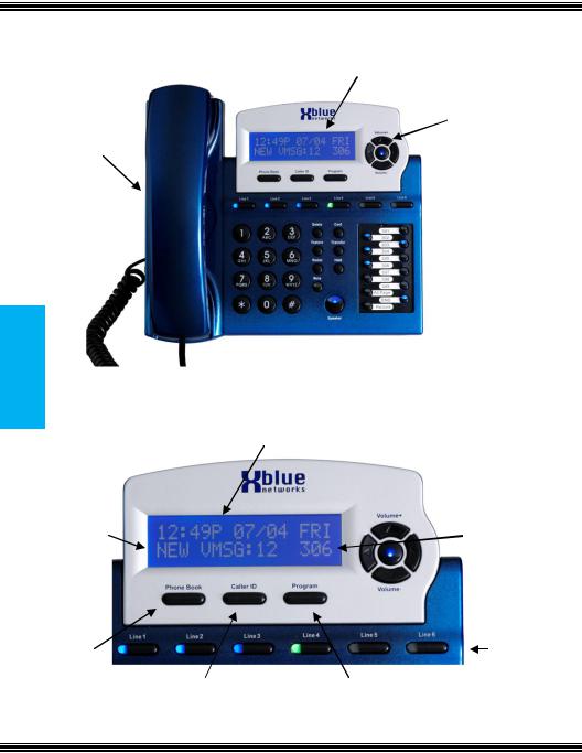
Getting to Know the X16 Telephone |
Backlit Display |
|
the Know to Getting
Telephone X16
Navigation Keys
Integrated
Headset
Programmable
 Keys
Keys
 Speakerphone Button
The X16 Telephone Display
Time, Date and Day
|
|
|
Extension |
|
New Voicemail |
|
|
|
|
|
|
Number |
|
|
|
|
|
|
|
|
|
|||
|
|
|
|
|
Phone Book |
|
Line Keys |
||
|
Caller ID Log |
Program Key |
||
- 10 - |
Issue 2 |
Default Button Layout
CO Lines with
Integrated
CID
12 Key Dial Pad |
Programmable |
|
Feature Buttons |
||
|
Delete, Conference, Feature,
Transfer, Redial, Hold,
Mute and Speaker
Navigation keys
Scroll left or right, up and down to update the LCD Display.
Scroll Up
Voice Mail Access
Fwd to VM (lit)
Backup a level
Scroll Right
Scroll Left Next VM Message
Last VM Message
OK/Select/Confirm
Scroll Down
X16 Telephone
Getting to Know the
Issue 2 |
- 11 - |
X16 Installation Guide
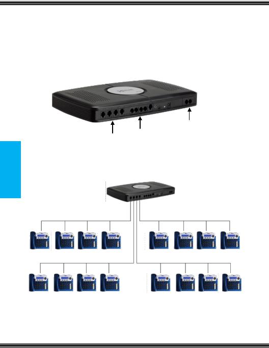
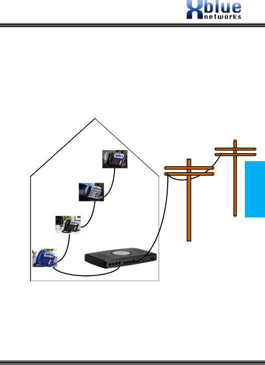
System Configuration
The X16 system is equipped to accommodate up to four central office lines and 16 X16 digital telephone endpoints and uses an advanced digital interface technology allowing one cable pair to support up to four digital telephone endpoints. Each digital telephone endpoint has its own extension number, and can be called from any other extension in the system.
System
Configuration
2 CO Line Expansion
CO Lines
Extensions
The digital telephone endpoints can be connected to the system in loop or series fashion, or they can be connected in home run, also known as start topology.
- 12 - |
Issue 2 |
Installation
Step 1 - Location
The X16 system should be located close to the telephone company interface (RJ21X), and have a dedicated outlet with an isolated ground.
The system can be mounted on the wall or placed on a table. Once the location of the system is determined use the supplied “System Wall Mount Template” to level and the provided screws to secure the system to the wall or place it on a table.
Do not tighten the screws all the way, leave about ¼ of an inch which will be used to lineup the “snowmen” on the back of the system. Place the X16 system over the screws and slide it into place.
Configuration
System
Issue 2 |
- 13 - |
X16 Installation Guide
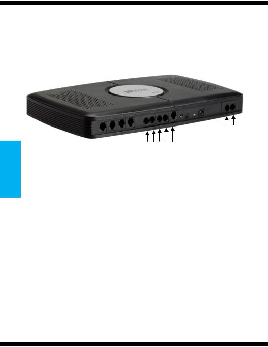
Step 2 – CO Line Connections
The X16 system supports a single CO Line per port, or two CO lines in ports labeled 1/2 and 3/4.
Note: The port labeled “Line 1” is a direct access auxiliary port for line 1 allowing an analog device direct access.
System
Configuration
6 5
4 3/4 2 1/2 AUX CO Lines
Telephone lines are usually found on the center pair (White/Blue) of the telephone jack (RJ11). Sometimes a second line will be connected to the outer pair (White/Orange). The system is design to accommodate both types of installations. When using only the center pair, connect 1 telephone line to each of the 4 ports in the system. When using both the center and outer pairs, use only ports labeled 1/2 and 3/4 to connect all 4 lines. The existing cabling will determine how the telephone lines will be connected to the system.
Note: The port labeled “Line 1” gives you access to the telephone company line
(white/blue) plugged into the Central Office Port labeled 1/2. This is useful during a Power Failure or anytime you want to access to line 1 from an Analog telephone.
|
Line |
|
|
Port Number |
|
|
|
|
|
||
|
AUX CO |
|
|
Line1 |
|
|
CO Line 1 |
|
1 / 2 |
|
|
|
CO Line 2 |
|
2 |
|
|
|
CO Line 3 |
|
3 / 4 |
|
|
|
CO Line 4 |
|
4 |
|
|
|
CO Line 5 |
|
5 |
|
|
|
CO Line 6 |
|
6 |
|
|
- 14 - |
Issue 2 |
Step 3 – Telephone Endpoint Connection
The X16 comes standard with four RJ11 extension ports. Each port supports up to 4 proprietary digital telephone endpoints, for a total of sixteen (16) endpoints. Each port on the system will support up to 600 feet of cable.
In a Loop wiring or serial cable topology 600 feet is calculated by adding the distance of the initial run plus the distance between each telephone.
Configuration
System
Cable A to telephone 1 + (distance between telephone1 & telephone 2) + (distance between telephone 2 & telephone 3) + (distance between telephone 3 & telephone 4) <= 600 feet.
Issue 2 |
- 15 - |
X16 Installation Guide
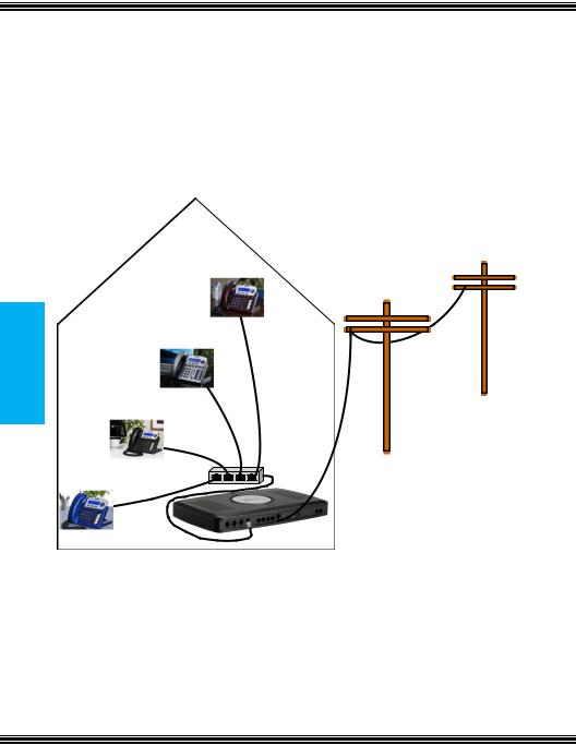
Home Run wiring, also known as star topology can be found in office buildings and newer homes. In this wiring scheme each of the four X16 telephones are plugged into a “4 Telephone Connector”, which is then connected into one of the ports on the X16 system.
System
Configuration
In a star topology 600 feet is calculated by adding each Digital Telephone endpoints cable run.
Cable A + Cable B + Cable C + Cable D <= 600 feet.
- 16 - |
Issue 2 |
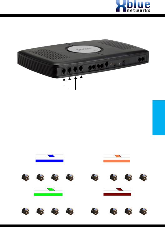
The extensions are labeled 1 ~ 16, and each port accepts up to four telephones.
13~16
9~12
Extensions
5~8 1~4
Connect the X16 telephone endpoints to the system using one RJ11 port, for up to four different endpoints, with a maximum cable length of 600 feet per port. Once connected each telephone endpoint will register with the voice server once it is powered up. At default, the extensions begin with number 301. The remaining extension numbers must be entered. See step 5.
X16 Cable Pair
White |
|
|
Blue |
|
|
|
|
|
|
|
|
Ports 1~4 |
|
|
|
|
|
|
|
301 |
|
302 |
303 |
304 |
|
|
|
|
|
|
|
|
|
|
White |
|
|
Green |
|
|
|
Ports 9~12 |
|
|
|
|
|
|
|
309 |
|
310 |
311 |
312 |
|
|
|
|
|
White |
|
|
Orange |
||
|
Ports 5~8 |
|
|
|
|
|
|
|
|
|
|
305 |
306 |
|
307 |
|
308 |
|
|
|
|
|
|
|
|
|
|
|
|
White |
|
|
|
Brown |
|
|
|
|
|
||
|
Ports 13~16 |
|
|
||
|
|
|
|
|
|
313 |
314 |
|
315 |
|
316 |
|
|
|
|
|
|
Configuration
System
Issue 2 |
- 17 - |
Device Endpoint
X16 Installation Guide
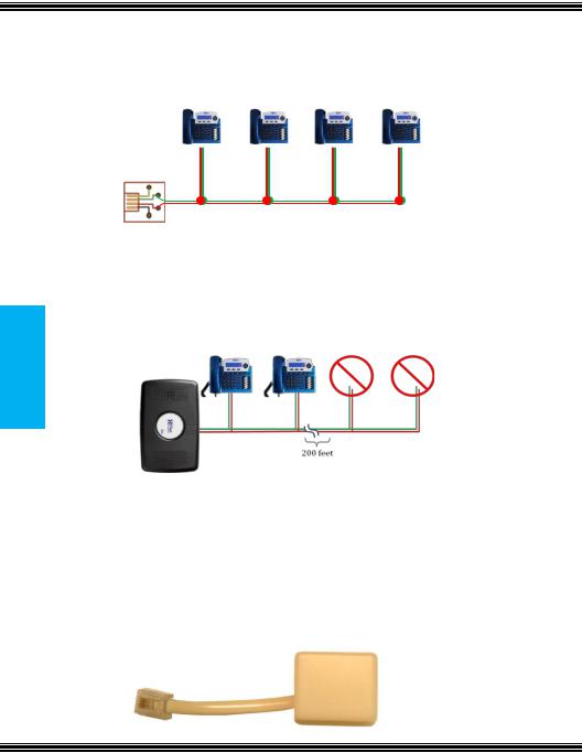
Leaving any ports punched down but not connected to a telephone, may result in erratic operation.
Correct Installation process
It is important to connect a telephone to every jack that is connected to the system. Extensions connected to a cable with “Bridge Taps”, may experience distortion. If locating a bridge tap is not practical, a quick resolution is to use a different cable pair such as the Yellow/Black or White/Orange.
Note: There should not be any unconnected telephones at the end of a cable run that is over 200 feet.
Endpoint Device
Every live telephone jack connected to the system will receive a data signal. If the system finds an open jack (bridge tap) the data signal may be lost, causing the remaining digital telephone endpoints to receive erroneous data, which may lead to improper operation. Therefore, for proper operation each live telephone jack at the end of a cable run, connected to the system, must have either a digital telephone endpoint or an endpoint device. Symptoms of an open jack include – but not limited to - voice distortion, static and slow speakerphone reaction when the button is pressed, problems accessing CO Lines, etc.
- 18 - |
Issue 2 |

Punch Down
In this example, system ports 10 through 16 do not have telephones connected to them but they are still “punched down” on the system.
Generally, this will not be a problem unless the cable is over 200 feet in length.
Punch Down
Issue 2 |
- 19 - |
X16 Installation Guide
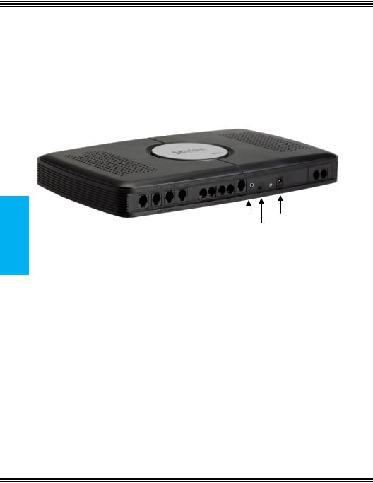
Step 4 – Power up and Initialization
To power up the system, and bring it on line, connect the external power supply to the system. To initialize the system, once the blue LED begins flashing at 1 impulse per second (IPS), switch the “init switch” back and forth three times and the LED will begin flashing at rapid rate, for 5 seconds and then return to 1 IPS.
Note: For proper operation, be sure to reboot the system, by unplugging the power cable, and then plugging it back in. This will ensure that all of the extensions are connected to the server correctly.
Down Punch
MOH Port Power Input
Initialization Switch
Step 5 – Extension Numbering
One extension in the system will automatically be numbers 301. All other telephones will have to have their extension numbers entered when they are connected to the system. Valid numbers are 302 to 399. To program the extension number please refer to Phone Setup (see Page 13), in the programming section.
The system becomes fully functional after all extensions are registered. Extensions may be moved from one port to another simply by unplugging the unit and plugging it into another active port. If the extension is unplugged for longer than 120 seconds (2 minutes) the port may initialize, and revert back to factory default – This includes all personal voice mail settings (greetings and saved messages). Any port that is active must have either a telephone or an Endpoint Device connected to it, or distortion may be heard.
Note: An “Endpoint Device” may be needed when relocating an extension.
- 20 - |
Issue 2 |
2 CO Line Expansion Module
The X16 system comes with four CO Lines, and can be expanded to six CO Lines, when the 2 CO Line expansion module is installed.
2 CO Line Expansion Module
The expansion module is located inside the communication server and connects to the main board, via ribbon cable. After it is installed, and the system is powered on, the expansion module will be recognized in software and become fully operational. Use the following steps to install the expansion module.
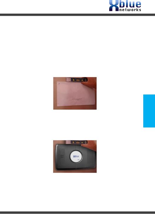
Step 1 – Installing the Expansion Module
Place the voice server face down on a stable surface such as a table, showing the four rubber feet.
Rubber Feet
Remove the four rubber feet, placing them in a safe place, such as the back of the voice server, exposing 4 screws. Unscrew the four screws and remove the cover.
 Philips Head Screws
2 CO Line Expansion Module
Issue 2 |
- 21 - |
X16 Installation Guide
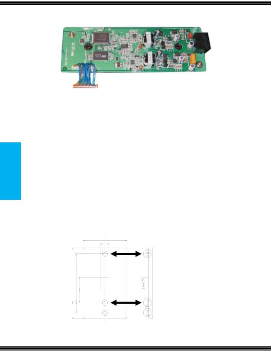
Step 2 – Insert the Expansion Module
Remove the plastic tab found on the front of the Voice server. Insert the RJ14 connections through the front of the voice server and secure the card with the provided screws. Connect the ribbon cable from the expansion module to the main board and replace the cover. Place the provided black plastic encasement window around the newly installed card.
Wall Telephone
Mount
Telephone Wall Mount
When wall mounting an X16 Digital Telephone Endpoint be sure to use the inner posts (3.26 inches) on an adjustable wall mount plate. If this plate is not available, use the “Telephone Wall mount” template, which can be found on the “System Wall Mount Template” used in step 1 (
Page 13) of the installation section.
- 22 - |
Issue 2 |
 Loading...