

Page 1

by
Digital Inverter 200 W ,
400 W, 800 W
Owner’s Guide
Page 2

About Xantrex
Xantrex Technology Inc. is a world-leading supplier of advanced power electronics and
controls with products from 50 watt mobile units to one MW utility-scale systems for
wind, solar, batteries, fu el cells, microturbines, and backup pow er applications in both
grid-connected and stand-alone sys tems. Xantrex products include inverters, battery
chargers , programmable power supplies, and variable speed drives that convert, supply,
control, clean, and distribute electrical power.
Trademarks
Digital Inverter 200 W, 400 W, 800 W is a trademark of Xantrex International. Xantrex is
a registered trademark of Xantrex International.
Other trademarks, registered trademar ks, and product names are the pr operty of their
respecti ve ow ners and are used herein for identification purposes only.
Notice of Copyright
Digital Inverter 200 W, 400 W, 800 W Owner’s Guide © October 20 05 Xan tr e x
Internati ona l. All r ights r es er ved .
Disclaimer
UNLESS SPECIFICALLY AGREED TO IN WRITING, XANTREX TECHNOLOGY INC. (“XANTREX”)
(a) MAKES NO WARRANTY AS TO THE ACCURACY, SUFFICIENCY OR SUITABILITY OF ANY
TECHNICAL OR OTHER INFORMATION PROVIDED IN ITS MANUALS OR OTHER DOCUMENTATION.
(b) ASSUMES NO RE SPONSIBILITY OR LIABILITY FOR LOSS OR DAMAGE, WHETHER DIRECT,
INDIRECT, CONSEQUENTIAL OR INCIDENTAL, WHICH MIGHT ARISE OUT OF THE USE OF SUCH
INFORMA T ION. THE USE OF ANY SUCH INFORMATION WILL BE ENTIRELY AT THE USER’S RISK.
Date and Revision
October 2005 Revision B
Part Number
975-0176-01-01
Contact Information
Te lephone: 1 360-925- 5097
Fax: 1 360-925- 5143
Web: www.xantrex.com/support
Page 3

Contents
1. Introduction . . . . . . . . . . . . . . . . . . . . . . . . . . . . . . . . . . . . . . . . . . 1
About This Guide . . . . . . . . . . . . . . . . . . . . . . . . . . . . . . . . . . . . . 2
2. Important Safety Information. . . . . . . . . . . . . . . . . . . . . . . . . . . . 3
Warnings and Cautions . . . . . . . . . . . . . . . . . . . . . . . . . . . . . . . . . 3
Additional Safety Guidelines . . . . . . . . . . . . . . . . . . . . . . . . . . . . 5
3. Digital Inverter Features . . . . . . . . . . . . . . . . . . . . . . . . . . . . . . . . 6
AC (Front) Panel . . . . . . . . . . . . . . . . . . . . . . . . . . . . . . . . . . . . . . 6
DC (Back) Panel . . . . . . . . . . . . . . . . . . . . . . . . . . . . . . . . . . . . . . 8
Digital Display (Top) Panel . . . . . . . . . . . . . . . . . . . . . . . . . . . . . 10
Types of Connections . . . . . . . . . . . . . . . . . . . . . . . . . . . . . . . . . 12
Accessories . . . . . . . . . . . . . . . . . . . . . . . . . . . . . . . . . . . . . . . . . 13
4. Connecting the Digital Inverter . . . . . . . . . . . . . . . . . . . . . . . . . 14
Choosing a Location . . . . . . . . . . . . . . . . . . . . . . . . . . . . . . . . . . 14
Connecting for Loads Under 150 W . . . . . . . . . . . . . . . . . . . . . . 15
Connecting for Loads Over 150 W . . . . . . . . . . . . . . . . . . . . . . . 16
5. Operating the Digital Inverter . . . . . . . . . . . . . . . . . . . . . . . . . . 19
Operating Conditions and Guidelines . . . . . . . . . . . . . . . . . . . . . 19
Shutting the inverter off . . . . . . . . . . . . . . . . . . . . . . . . . . . . . . 20
Operating normal loads . . . . . . . . . . . . . . . . . . . . . . . . . . . . . . 21
Operating loads with high surge requirements. . . . . . . . . . . . . 22
Page 4

6. Maintaining Battery Condition . . . . . . . . . . . . . . . . . . . . . . . . . .24
7. Troubleshooting. . . . . . . . . . . . . . . . . . . . . . . . . . . . . . . . . . . . . . .26
Common Problems . . . . . . . . . . . . . . . . . . . . . . . . . . . . . . . . . . . 27
Buzz in audio systems. . . . . . . . . . . . . . . . . . . . . . . . . . . . . . . . 27
Television interference . . . . . . . . . . . . . . . . . . . . . . . . . . . . . . . 27
Troubleshooting Reference . . . . . . . . . . . . . . . . . . . . . . . . . . . . 28
8. Specifications . . . . . . . . . . . . . . . . . . . . . . . . . . . . . . . . . . . . . . . . .31
9. Warranty and Return. . . . . . . . . . . . . . . . . . . . . . . . . . . . . . . . . .33
10. Other Xantrex Products . . . . . . . . . . . . . . . . . . . . . . . . . . . . . . .39
iv
Page 5

1 Introduction
Thank you for purchasing the XPower Digital Inverter 200 W, 400 W,
800 W. These Digital Inverters are part of a family of advanced highperformance powe r invert ers f rom Xant rex, t he leade r in h igh freq uency
inverter design.
Connected to the 12 volt outlet in your car, truck, boat, RV, or directly
from a dedicated 12 V battery (400 and 800 W only), the Digital
Inverter efficiently and reliably po wers a wide variety of household AC
products, such as portable stereos, laptop computers, TVs, VCRs, and
other similar products.
The Digital Inverter uses reliable solid state power electronics for years
of safe, trouble-free operation and includes the following automatic
features to ensure safe and trouble-free operation:
• Low batt er y al ar m
• Low voltage shutdown
• High voltage shutdown
• Overload shutdown
• Overheating shutdown
• Short-circuit protection
1
Page 6

About This Guide
To get the best performance from your Digital Inverter, we recommend
that you read this guide before connecting and using the Digital
Inverter. Save this guide for future reference.
This guide contains:
• Important safe ty info rmation (page 3)
• Digital Inverter features (pa g e6)
• Instructions for connecting the inverter (page 14)
• Operating guidelines (page 19)
• Troubleshooting information (pa ge 26)
• Specific ations (page 31)
• Warranty and service inform ation (page 33)
2
Page 7
2 Importa nt Safety Info rmation
Misusing or incorre ctly connecting the Digital Inverter 200 W, 400 W,
800 W may damage the equipment or create hazardous conditions for
users. Rea d the fol lowi ng sa fety in struc tio ns and pay sp ecia l atte ntion t o
all Caution and Warning statements in the guide.
Warnings identify
of life.
Cautions identify conditions or practices that may damage the unit or
other equipment.
Warnings and Cautions
WARNIN G: Shock hazard
Keep children away from the Digital Inverte r inverter. The inverter
generat es the same potential ly lethal AC power as a norm al household
wall outl e t . Treat th e outlet w ith re sp ec t!
WARNIN G: Heated surface
The Digital Inverter housing may become uncomfortably warm,
reaching 140° F (60° C) under extended high power operation . Ensure
that at least 2 inches (5 cm) of air surround the invert er. During
operat ion, keep it away fr o m materials that may be affected by high
temperatures.
conditions that may result in personal injury or loss
3
Page 8

WARNIN G: Explosion hazard
Do not use the Digital Inverter in the presence of flammable f um es or
gases, such as in the bilge of a gasoline powered boat, or near propane
tanks. Do not use the Digital Inverter in an enclosure containing
automoti ve-type, lead-acid batteries. These batteries, unlike sealed
batteries, vent explosive hydrogen gas, which can be ignited by sparks
from electrical connect ions.
WARNIN G: Crash hazard
Vehicle d rivers should not configure or troublesh oot the Digital Inverter
while they are driving the ve hicle.
CAUTION: Output non-sinusoidal
Some chargers for small nickel-cadmium batteries can be damaged if
connect ed to the Digital Inverter. Do not use the invert er with the
following appliances:
• Small battery-operated appliances like rechargeable flashlights,
some rech ar geabl e sha vers, an d night l ights th at ar e pl ug ged dir ec tly
into an AC re ce p ta cle to rech arg e .
• Battery chargers used in hand power tools. These chargers display a
warning label stating that dangerous voltages are present at the
charger battery terminals.
4
Page 9
CAUTION
Do not connect live AC power to the Digital Inverter’s AC outlets. The
inverter will be damaged even if it is turned off.
Do not connect any AC load that has it s neutral conductor connected to
ground to the Digital Inverter.
Additional Safety Guidelines
• Do not insert foreign objects in the Digital Inverter outlets or
ventilation openings.
• Never connect the inverter to power utility AC distribution wiring.
• Do not use the Digital Inver ter in temperatures over 100° F (40° C).
• Do not expose the Digital Inverter to water, rain, snow, or spray.
Failure to follow these safety guide lines may cause personal inj ur y and/
or damage to the Digital Inverter. It may also void your product
warranty.
5
Page 10
3 Digital In vert er Features
This section des cribes the main features of the Digital Inverter.
CAUTION
To prevent overheating, ensure that all the vent ilation openings on the
unit ar e kept clear.
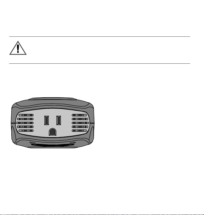
AC (Front) Panel
Figure 1 shows the AC panel of the 200 W unit.
OUTPUT: 115 VAC 60 HZ
160 W/1.4A Continuous
Figure 1
AC Panel of 200 W unit
An AC receptacle is loca ted on one end of the 200 W unit. You can plug
in 120 V appliances with a combined tot al continuo us power
consumption of 160 W or les s when the inverter is turned on.
6
Page 11
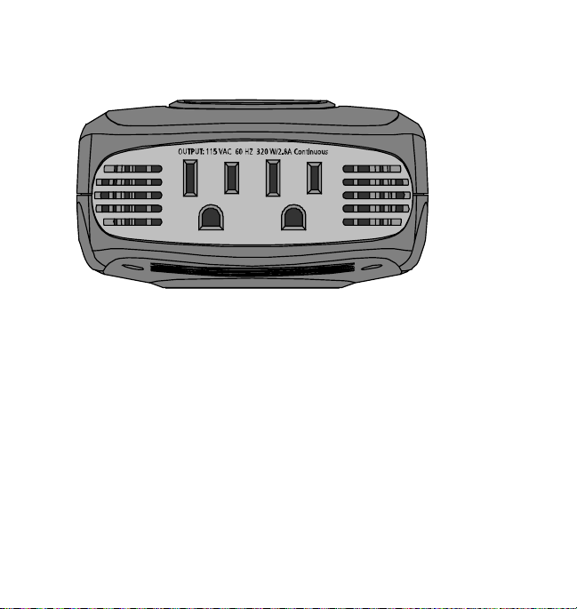
Figure 2 shows the AC panel of the 400 W unit, which is very similar to
the 800 W unit.
Figure 2
Two AC receptacles are located on one end of the 400 W unit and the
800 W unit. You can plug in 120 V appliance s with a combined total
continuous power consumption of 320 W (400 W unit) or 640 W
(800 W unit) or less when the invert er is turned on.
AC Panel of 400 W unit
7
Page 12
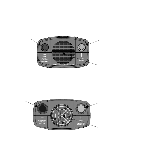
DC (Back) Panel
Figure 3 shows the DC pane l of the 200 W unit. Use Table 1 to identify
the function of ite ms.
Figure 3
2B
DC Panel of 200 W unit
2A
1
Figure 4 shows the DC panel of the 800 W unit, which is very similar to
the 400 W unit. Use T able 1 to identify the function of items.
2B
Figure 4
DC Panel of 800 W unit
2A
1
8
Page 13

Table 1
Item Function
DC Panel Functions
1
2
Fan and Ventilation Openings
The cooling fan on the units are designed to operate only when
output powe r is greater than approximately 80 W. When the inverter
is turned on, the fan may operate momentarily . The ventilation
openings should not be covered at any time while the inverter is
operating.
A) Positive and B) Negative Cablin g Terminals
Connect th e ri ng te rmi nal s on the p ower cables to th ese ter mina ls. To
ensure correct polarity, red must b e connected to red and black must
be connected to black.
9
Page 14

Digital Display (Top) Panel
Figure 5 shows the Digital Display panel. Use Table 2 to identify the
function of items.
3
2
1
Figure 5
10
Digital Display Panel
Page 15

Table 2
Item Function
Digital Display Panel Functions
1 Switch to t u rn the unit on and off.
Press to toggle the display function to show input voltage, output
power and output voltage.
2 Normal Operation
Digital display shows input voltage, output power and output
voltage.
Error Mode
Digital display shows error codes and alarm sounds w hen unit has
shut down d ue t o under - vo ltage , o ver -vo lt age, o ver-load, overhea ti ng
or high -surge .
3 LEDs indicate the status of the digital di splay.
Audible Alarm
An audible alarm wa rns you i f an und er -vol t age shut down is abo ut to
occur.
11
Page 16

Types of Connections
Product Lighter Plug Connection
Cable Clamps/Battery
Connections
200 W unit Avai lable – You must connect
a separate lighter plug cabl e
(included).
400 W unit Avai lable – You must connect
a separate lighter plug cabl e
(included).
800 W unit Not Available Available – You must connect
Not Available
Available – You must connect
a separate battery clamp cable
(included).
a separate battery clamp cable
(included).
12
Page 17

Accessories
Figure 6 shows the lighter plug cable that is included with the 200 W
unit and 400 W unit.
Figure 6
Figure 7 shows the cable s upplied with the 400 W unit and 800 W unit
for direct connect ion to a 12 V battery.
Figure 7
Lighter Plug Cable
Cable for Direct Conne ction to a 12 V Battery
13
Page 18

4 Connecti ng the Digital Inverter
CAUTION
The Digital Inverter must only be connected to a battery that has a
nominal output of 12 V. It will not operate if connected to a 6 V battery
and may be damaged if connected to a battery with 16 V or more.
It is recommended that you hard wire the 800 W unit directly to the
12 V battery.
Choosing a Location
For best performance, place the inverte r on a fla t surface in a location
that is:
Dry Do not expose t he inverter to water, rain, snow or spr ay.
Cool Operate the inverter in ambient temperatures between 0°C
Well-ventilated For proper cooling, allow at least 2 inches (5 cm) of
Clean and free of
dust and dirt
Safe Do not ins tall the inverter in a compartment with batteries
14
and 40 °C (32 °F and 100 °F). Keep it away from hea ting
vents and direct sunlight.
clearan ce around the inverter.
Choose a loca tion that is free of any debris that could get
into the inverter.
or flammabl e liquids, such as gasoline, or explosive vapors.
Page 19

Connecting for Loads Under 150 W
Follow these steps to connect the 200 W unit or 400 W unit:
1. Place the inverter on a flat surface such as the flo or of your vehicle.
2. Make sure that the unit is off by verifying the digital display is off.
3. Take the power cord equipped with the lighter plug (Figure 6) and
place the ring terminals over the two cabling terminals on the bac k
of the inverter. (The cabling terminals are shown in Figure 3 and
Figure 4.)
CAUTION: Reverse polarity
Power connections of the 12 V DC battery to the Digital Inverter must
be positive to positive and negative to negative.
A reverse polari ty connection (positive to negative) w ill blow a fuse in
the inverter and may permanently damage the unit. Damage caused by a
reverse polarity connecti on is not covered by your warranty.
CAUTION
Make sure you connect r ed to red and black to black, and make sure you
screw th e n ut s on tig h tly.
4. Fasten the posit ive (red ) clam p to the posit ive bat ter y post , and th en
fasten the negative (black) clamp to the negative battery post.
15
Page 20

5. T ighten the nut on each DC terminal until it is snug. Do not
over-tighten.
6. Plac e the inverter’s lighter plug in the vehicle’s lighter socket or a
12 V outlet.
7. T urn on the unit by holding the switch located on top of the unit
until 888 is shown on the display.
The digital displ ay will s how the ba ttery vol ta ge, ind icati ng th at the
Digital Inverter is operating normally and AC powe r is available at
the outle t.
8. Plug in the AC product you want to operate.
When not in use always turn the inverter off by holdi ng the switch until
the digital di splay turns off.
Connecting for Loads Over 150 W
You must connect the 400 W unit or 800 W unit directly to a 12 V
battery if you are going to operate loads greater than 150 W
continuousl y. When the inverter is connected this way, you can operate
loads of any size up to 320 W continuously with a 400 W unit and
640 W continuous ly with a 800 W unit.
16
Page 21

WARNIN G: Shock hazard
Batter ies contain corrosi ve materials and present an electrical shock
hazard. To prevent irritation and burns, wear protective eyew ear and
clothing wh en you install the in verter or work with the batteries. Take
special care to ensure that m etal tools and personal metal objects like
rings and bracelets do not contact the battery terminals.
Follow these steps to make a direct battery connection:
1. Place th e in v er t er on a fl at su rface.
2. Make sure that the unit is off by verifying the digital display is off.
CAUTION: Reverse polarity
Power connections of the 12 V DC battery to the Digital Inverter must
be positive to positive and negative to negative.
A reverse polari ty connection (positive to negative) w ill blow a fuse in
the inverter and may permanently damage the unit. Damage caused by a
reverse polarity connecti on is not covered by your warranty.
3. Take the cables equi pped with ba tt ery cla mps on one e nd (Figu re 7)
and place the ring terminals over the two cabling terminals on the
back of the inverter. (The cabling terminal s are shown in F igure 3
and Figure 4.)
17
Page 22

CAUTION
Make sure you connect red to red and black to black, and make sure you
screw th e n ut s on tig h tly.
4. Fasten the posit ive (red ) clam p to the posit ive bat ter y post , and th en
fasten the negative (black) clamp to the negative battery post.
5. T urn on the unit by holding the switch located on top of the unit
until 888 is shown on the display.
The digital displ ay will s how the ba ttery vol ta ge, ind icati ng th at the
Digital Inverter is operating normally and AC powe r is available at
the outle t.
6. Plug in the AC appliance you want to operate.
When not in use, always turn the inverter off by holding the sw itch until
the digital display turns off.
18
Page 23

5 Operating the Digital Inverter
This section explains how to operate the Digital Inverter most
efficiently.
Operating Conditions and Guidelines
This section describes normal operation as well as conditions that
trigger an ala rm or automatically shut down the Digital Inverter.
Normal Operation When you connect the inverter to the vehicle’s
lighter socket or directly to a 12 V battery and turn on the unit, the
digital display will show input voltage, the input voltage
illuminates and AC power is available at the outlets. You can now plug
in your AC products and turn them on one at a time.
Low Battery Alarm and Shutdown As the battery discharges, its
voltage decreases. When the Digita l I nverter senses that the voltage at
its DC input has dropped to 11.0 V, it sounds an alarm, giving you time
to shut down sensitive loads such as computers. If you ignore the alarm,
and the DC input voltage drops below 10.5 V, the inverter shuts down
all loads to save the battery fr om furt her discharge. The under-v oltage
error code ‘E01’ will show on the digital display.
LED
19
Page 24

High-input Voltage Shutdown If a defective battery charging system
causes the battery voltage to rise to dangerously high levels, the Digital
Inverter shuts down autom atically. The over-voltage error code ‘E02’
will show on the digital display.
Overload Shutdown If you connect an AC load that is rated too high
(see Table 3) or a lo ad that dra w s ex ce s si v e s u rge po w e r, the Digi t al
Inverter shuts down. The overload error code ‘E03’ will show on the
digital display.
Overheating Shutdown The Digital Inverter shuts down
automa t i cal l y if it ex ce ed s it s sa f e o pe r at in g te m p er a tu r e. The
overheating error code ‘E04’ will show on the digital display.
Shutting the inve rter off
• If you are going to dis connect the battery, turn the inverter off firs t.
• Turn the inverter off by holding the s witch until the display turns
off.
20
Page 25

Operating normal loads
The Digital Inverter is capable of continuously poweri ng most 120 V
AC products with the following power rating maximums:
Table 3
Product
200 W unit 200 W 160 W 400 W
400 W unit 400 W 320 W 700 W
800 W unit 750 W 640 W 1200 W
Power and Surge Ratings
5 min Max .
Power Rating
Continuous
Power Rating
Surge Ratin g
Max.
The inverter’s AC (“modified sine wave”) output waveform is designed
to function similarly to the sine wave shape of utility power. Most AC
products c orrect ly r ated for the power ra tin g maximu ms lis ted i n Table 3
or less will operate normally with the Digital Inverter.
21
Page 26

Operating loads with high surge requirements
The power , or wat tage rating, of AC loads is the average amount of
power they use. Some appli ances c onsume more power than t heir po wer
rating w h en they are first turned on. TVs, monitors, and electric motors
are some products that have high surge requirements at star t up. The
Digital Invert er ca n supply momentary surge power that is higher than
its maximum power rating. Some products rated less than power rati ng
maximum for your inverter may exceed its surge capability and trigger
an overload shutdown. If this problem occurs when attemptin g to
operate several AC products at the same time, try first turning on the
inverter with al l AC products turned off, then one by one turn each on,
starting with the high-surge product first.
22
Page 27

Table 4
Wattage of Common AC Products
a
Product
Cell phone/camcorder
charger
b
Watts
200 W unit 400 W unit 800 W unit
10 Yes Yes Yes
Video game console 20 Yes Yes Yes
Portable work light 25 Yes Yes Yes
Stereo system 50 Yes Yes Yes
Laptop computer 75 Yes Yes Yes
13" TV 100 Yes Yes Yes
27" TV 200 Yes Yes
20" TV/VCR combo 300 Yes Yes
Small appliances 400+ Yes
Power tools 400+ Yes
a.Power requirements for product ex amples are estimates onl y. To calcu late the wattage of a product, use
the following equation: amperage x 115.
b.If you want to power two or more products simultan eously, add th e power requirements of both prod-
ucts to determine the total wattage.
23
Page 28

6 Mainta ining Battery Condition
The battery operating time of the Digital Inverter depends on the charge
level of the battery, battery capacity, and the amount of power drawn by
the AC loads you are operating. With a typical vehicle battery, you can
expect the following:
Table 5
Inverter L oa d Sample Appliance Operating Time
200 W unit 50 W CD playe r 6–8 hours
400 W unit 100 W small TV 3–4 hours
800 W unit 200 W TV/VCR 1–2 hours
24
Battery Operating Times
Page 29

Here are some guidelines that will help to preserve your battery:
• Vehicle batteries are not designed for repeated deep-discharge
cycles, and cons tantl y rechar gi ng a vehic le’s battery will s horten it s
life. Therefore, when you are using a vehicle battery as a power
source, star t the vehicle every hour or two to recharge the battery.
• The Digita l Inverter will operate while the engine is running, but
the voltage drop that occurs when the engine starts may trigger a
low-voltage shutdown.
• Vehicle batteries are designed to provide brief periods of very high
current needed for engine starting. They are not intended for
constant deep discharge. Regularly operating the Digital Inverter
from a vehicle battery until the low-voltage alarm sounds will
shorten the li fe of the battery. Cons ider connecting the Digital
Inverter to a separate deep discharge-type batte r y if you will be
frequently running electrical products for exten ded periods of time.
• If you are not going to use the Digital Inverter for a few days, tur n
off the unit. The in verter d raws 0. 4 A or less whe n th e unit is on and
no load is co nnected, but it will eventually discharge the battery.
25
Page 30

7 Troubleshooting
This sect ion will help you identify the source of most problems that can
occur with the Digital Inverter.
If you have a problem with the inverter, please review this section
before contacting your dealer. If you are unable to solve a problem and
need to contact service, please prepare for the call by writing down the
following details:
• Inverter’s serial number
• How long the inverter has been in use
• Where it is ins talled
• Appliances operating when the problem occurred
• A brief description of the problem
26
Page 31

Common Problems
WARNIN G: Electrical shock and burn hazard
Do not disas semble the Digital Inverter. It does not contain any userservic eab le pa rts. At te mp ting t o s er vic e the in ve rter yo urs el f cou ld resu lt
in an electrical shock or burn.
Buzz in audio systems
Some inexpensive stereo systems have inadequate internal power
supply filteri ng and buzz slight ly when powered by the Digital Invert er .
The best solut ion is to use an audio system with a high-quality filter.
T elevision interference
The Digita l I nverter is shielded to minimize interference with TV
signals. If TV signals are weak, you may see interfe renc e in the form of
lines scrolling across the screen. Try one of these suggestions to
minimize or eliminate the problem:
• Adjust the orientation of the Digital Inverter, television, antenna,
and cables.
• Maximize T V sign al strength by using a better antenna, and us e
shielded antenna cable where poss ib le.
• Try a different TV. Different models vary considerably in their
suscept ibility to interference.
27
Page 32

Troubleshooting Reference
This section describes problems, their symptoms, possible causes, and
solutions.
Problem: The AC load will not operate. Digital display is off.
Possible Cause Solution
Battery is defective. Check battery and replace if required.
The invert er ha s been co nne ct ed
with rever se DC input polarity.
Loose cable connections. Check cables and conne ctions.
Problem: The inverter will run some small loads, but not larger ones.
Possible Cause Solution
Voltage drop across DC cables. Shorten ca bles or use heavier cab les.
28
Check connection to battery.
The inverter has likely been damaged and
needs to be re paired.
Have the unit repaired (not covered under
warranty).
Tighten as required.
Page 33

Problem: Measured inverter outp ut is too low.
Possible Cause Solution
A standard “average-reading”
AC volt me ter has been use d to
measure out put voltage,
resulting in an apparent reading
5–15 V too low.
The battery voltage is too low. Recharge the batte ry.
For accurate measurement, the Digital
Inverter m odified sine wave output requires
a “true RMS” vo ltmeter for accu rate
measurements.
Problem: Battery run time is less than expected.
Possible Cause Solution
The AC product po w er
consumpti on is higher than
rated.
The batter y is old or defective. Replace the battery.
The battery i s not be in g char ge d
properly.
Power dissi pation in DC cables. Use shorter/ heavier DC cables.
Use a larg er battery to make up for the
increased power requirement.
Some chargers are not able to fully recharge
a battery. Make sure th at you use a power fu l
charger.
29
Page 34

Problem: The AC load will not ope rate, error code shows on di gi tal
display and alarm is sounding.
Error Possible Cause Solution
E01 Low voltage shutdown because
battery is discharged.
E02 Over- volt age shutdo wn be cau se
of high input voltage.
E03 The AC product(s) connected
are rated at more than the
inverter’s continuous power
rating; overload shutdown has
occurred.
E04 The inver ter ha s overhe at ed due
to poor ve ntilation.
Overheating shutdown has
occurred.
E05 The AC products connected
have a sur ge po wer tha t excee ds
the Digital Inverter’s surge
capability or the AC products
connected are short-circuited
and shut dow n has occurred.
Recharge battery.
Shorten cables or use heavier
cables.
Verify the cha rgi ng system is
properly regulated and the battery
is 12 V nominal .
Use a produc t w ith a power rating
within th e in v er te r’s continuo u s
power rat ing (see Table 3).
Turn inverter off and allow to cool
for 15 minutes. Clear blocked fan
or remove objects covering un it.
Move the inverter to a co o ler
place. R educe load if continuous
operation is requir ed .
The products exceed t he inverter’s
surg e capability. Use a product
with a starting surge power within
the Digi tal Inverter’s capability.
30
Page 35

8 Specifications
Specifications are subject to change without notice.
200 W uni t 400 W unit 800 W unit
AC output voltage (nominal) 120 V AC
DC input voltage range 10.5–15.5 V DC
Maximum continuous AC
output powe r
5 minutes AC output power 200 W 400 W 750 W
Maximum AC output surge
power
AC output frequency 60 ± 1 Hz
AC output wavef orm Modified Sine Wave
No load current dr aw
(at 12 V input )
Efficiency (maximum) 90%
Ambient ope rating
temperature range
Storage temperature -20–60 °C -4–140 °F
160 W 320 W 640 W
400 W 700 W 1200 W
0.3 A 0.3 A 0.4 A
0–40 °C 32–104 °F
a
31
Page 36

200 W uni t 400 W unit 800 W unit
6
-- -
5
8
-- -
1
2
-- -
1
2
-- -
3
8
-- -
a
Low voltage alarm
Low voltage shutdown
High voltage shutdown
Dimensions
(L × W × H)
11.0 V
10.5 V
15.5 V
102 × 84 × 51 mm
5
---
4 × 3 × 2"
1
11.0 V
10.5 V
15.5 V
137 × 102 × 51 mm
5 × 4 × 2"
11.0 V
10.5 V
15.5 V
141 × 114 × 61 mm
7 × 4 × 2"
We ight 10 oz (0.28 kg) 1 lb (0.44 kg) 1 lb 13 oz (0.82 kg)
a.Provides maximum 800 watts of AC output power for up to 1 minute.
32
Page 37

9 Warranty and Return
Warranty
What does this warranty cover? This Li mited Warranty is provided by
Xantrex Technology Inc. ("Xantrex") and covers defects in workmanship and
materials in your Digital In verter 200 W, 400 W, 800 W. This w arranty period
lasts for six (6) months from the date of purchase at the point of sale to you, the
original end user customer. You require proof of purchase to make warranty
claims.
What will Xantrex do? Xantrex will, at its option, repair or replace the
defect ive pr odu ct fr ee o f c har ge, pr ovided th at you n ot ify Xan trex o f th e pro duc t
defect withi n t he Warrant y Peri od, a nd prov ide d that Xan tr ex thr oug h i nspect i on
establishes the existence of such a defect and that it is covered by this Limited
Warranty.
Xantrex will, at its option, use new and/or reconditioned parts in performing
warrant y repai r and bu ildi ng repl ac ement pr oducts . Xa ntrex res erves the ri ght to
use par ts or pro duc ts of o ri gi nal or imp rov ed d esign in the repai r or repla ceme nt.
If Xantrex rep ai rs or repl ac es a pr oduc t, its warr an ty cont in ues for t he r emai ning
porti on of the original Warranty Period or 90 days from the date of the return
shipment to the customer , whichever is greater. All re placed products and all
parts removed from repaired products become the property of Xantrex.
Xantrex covers both parts and labor necessary to repair the product, and return
shipment to the customer via a Xantrex-selected non-expedited surfa ce freight
within the contiguous United States and Ca nada. Alaska and Hawaii are
exclude d. Contact Xantrex Cust om er Service for detai ls on freight policy for
return shipments outside of the contiguous United States and Canada.
33
Page 38

How do you get service?
If your product requires troubleshooting or w arranty service, c ontact your
dealer.
If you are unable to contact your de aler, or the dealer is unable to provide
service, contact Xantrex di rectly at:
Te lephone: 1 360-925- 5097
Fax: 1 360-925- 5143
Web: www.xantrex.com/support
Direct returns may be performed according to the Xantrex Return Material
Authorization Policy described in your product manual. For some products,
Xantrex maintains a network of regional Authorized Service Centers. Call
Xantrex or check our website to see if your product can be repaired at one of
these facilities.
What pro o f of purcha s e is requ i re d ? In any warranty claim, dated proof of
purchas e must accompany the product and the product mu st not have been
disassem bled or modified without prior written authorization by Xant rex.
Proof of pu rchase may be in any one of the following forms:
• The dated purchase receipt from the original purchase of the product at
point of sale to the end user , or
• The dated dealer invoice or purchase receipt showing original equipment
manufacturer (OEM) status, or
• The dated invoice or purchase rec eipt showing the product exchanged
under warranty
34
Page 39

What does this warranty not cover? This Limited Warranty does not cover
normal wear and tear of the product or costs related to the removal, installation,
or troubleshooting of the customer's electrical system s. This warranty d oes not
apply to and Xantrex will not be responsible for any defect i n or damage to:
a) the product if it has been misused, ne glected, improperly installed, physi-
cally dam aged or altered, either internally or externally, or damaged from
improper use or use in an unsuitable environment;
b) the product if it has been subjected to fire, wate r, generali zed corrosion,
biological infestatio ns, or input voltage that creates operat ing conditions
beyond the ma ximum or minimum limits listed in the Xantrex produc t
specifications including high input voltage from generators and lightning
strikes;
c) the product if repairs have been done to it other than by Xantrex or its
authorized service cent ers (hereafter " A SC s");
d) the product if it is used as a component part of a product expressly war-
ranted by another manufacturer;
e) th e pro d uc t if its origin a l id entifica tion (tra de -mark, ser i a l nu mber) ma rk -
ings have been defaced, altered, or removed.
Disclaimer
Product
THIS LIMITED W ARRANTY IS THE SOLE AND EXCLUSIVE WARRANTY
PROVIDED BY XANTREX IN CONNECTION WITH YOUR XANTREX PRODUCT
AND IS, WHERE PERMITTED BY LAW, IN LIEU OF ALL OTHER WARRANTIES,
CONDITIONS, GUARANTEES, REPRESENTATIONS, OBLIGATIONS AND
LIABILITIES, EXPRESS OR IMPLIED, ST ATUTORY OR OTHERWISE IN
35
Page 40

CONNECTION WITH THE PRODUCT, HOWEVER ARISING (WHETHER BY
CONTRACT, T ORT, NEGLIGENCE, PRINCIPLES OF MANUFACTURER'S
LIABILITY, OPERATION OF LAW, CONDUCT, STATEMENT OR OTHERWISE),
INCLUDING WITHOUT RESTRICTION ANY IMPLIED WARRANTY OR
CONDITION OF QUALITY, MERCHANTAB IL ITY OR FITNESS FOR A
PARTICULAR PURPOSE. ANY IMPLIED WARRANTY OF MERCHANTABILITY
OR FITNESS FOR A PARTICULAR PURPOSE TO THE EXTENT REQUIRED
UNDER APPLICABLE LAW TO APPLY TO THE PRODUCT SHALL BE LIMITED
IN DURATION TO THE PERIOD STIPULA T ED UNDER THIS LIMITED
WARRANTY.
IN NO EVENT WILL XANTREX BE LIABLE FOR ANY SPECIAL, INDIRECT,
INCIDENT AL OR CONSEQUENTIAL DAMAGES, LOSSES, COSTS OR EXPENSES
HOWEVER ARISING WHETHER IN CONTRACT OR TORT INCLUDING
WITHOUT RESTRICTION ANY ECONOMIC LOSSES OF ANY KIND, ANY LOSS
OR DAMAGE TO PROPERTY, ANY PERSONAL INJURY, ANY DAMAGE OR
INJURY ARISING FROM OR AS A RESULT OF MISUSE OR ABUSE, OR THE
INCORRECT INSTALLATION, INTEGRATION OR OPERATION OF THE
PRODUCT.
Exclusions
If this prod uct is a consumer pro duct, fede ra l law does no t al low an ex clusi on of
implie d warranties. To the extent you are entitled to implied w arranties under
federal law, to the extent permitted by applicable law they are limited to the
duration of this Limited Warranty. Some states and provinces do not allow
limitations or exclusions on implied warranties or on the duration of an im plied
warranty or on the limitation or exclusion of incidental or consequential
36
Page 41

damages, so the above limitation(s) or exclusion(s) may not apply to you. This
Limited Warranty gives you specific legal rights. You may have other rights
which may vary from state to stat e or province to province.
Warning: Limitations On Use
Please refer to your product manual for limitations on uses of the product.
SPECIFICAL LY, PLEASE NOTE TH AT THE DIGITAL INVERTER 200 W, 400 W,
800 W
SHOULD NOT BE USED IN CONNECTION WITH LIFE SUPPORT
SYSTEMS OR OTHER MEDICAL EQUIPMENT OR DEVICES. WITHOUT
LIMITING THE GENERALITY OF THE FOREGOING, XANTREX MAKES NO
REPRESENTATIONS OR WARRANTIES REGARDING THE USE OF THE
XANTREX
LIFE SUPPORT SYSTEMS OR OTHER MEDICAL EQUIPMENT OR DEVICES.
DIGITAL INVERTER 200 W, 400 W, 800 W IN CONNECTION WITH
Return Material Authorization Policy
Before returning a product dir ectly to Xantrex you must obtain a Return
Material A uthorization (RMA) number and the correct factory "Ship To"
address. Products must also be shipped prepaid. Product shipments will be
refuse d and returned at your expense if they are unauthorized, ret urned without
an RMA number cl early marked on the outside of the shippin g box, if they are
shipped collect, or if they are shipped to the wrong location.
37
Page 42

When you contact Xantrex to obtain service, please have your instruction
manual ready for reference and be prepared to supply:
• The serial number of your product
• Information about the installation and use of the unit
• Information about the failure and/or reason for the return
• A copy of your dated proof of purchase
38
Page 43

Return Procedure
1. Package the unit safely, pre ferably using the original box and packing
materi als. Please ensure t hat your product is shipped fully insured in the
original packaging or equiva lent. This warranty will not apply where the
product is damaged due to improper packaging.
2. Include the following:
• The RMA number supplied by Xantrex Technology Inc. clearl y
marked on th e outside of the box.
• A return address where the unit can be shipped. Post office boxes are
not acceptable.
• A contact telephone number where you can be reached during work
hours.
• A brief description of the problem.
3. Ship the unit prepaid to the address provided by your Xantrex customer
service representat ive.
If you ar e returning a product from outside of the USA or Canada In
addition to the above, you MUST inc lude return freight funds and are fully
responsible for all documents, duties, tariffs, and deposits.
If you ar e returning a product to a Xantrex Authorized Service Center
(ASC) A Xantrex return material authorization (RMA) number is not req u ired.
However, you must contact the ASC p rior to return ing the product or presenting
the unit to verify any return procedures that may apply to that particul ar facility.
39
Page 44

Out of Warranty Service
If the warranty period for your Digital Inverter 200 W, 400 W, 800 W has
expire d, if the unit was damaged by misuse or incorrect installation, if other
condition s of t he war ranty have not bee n met, or if no date d proo f of purc has e is
available, your unit may be serviced or replaced for a flat fee.
To return your Digital Inverter 200 W, 400 W, 800 W for out of warrant y
service, contact Xantrex Customer Service for a Return Material Authorization
(RMA) numbe r and follow the other st eps outlined in “Return Procedure” on
page 39.
Payment opt ions such as credit ca rd or money order will be explained by the
Customer Service Representative. In cases where the minimum flat fee does not
apply , a s wi th in compl et e uni ts or uni t s with exc ess ive d amage , an addi t ion al fe e
will be charged. If applicable, you will be contacte d by Customer Service once
your unit has been received.
10 Oth er X an trex Pro du ct s
To see the range of inverters and chargers offered by Xantrex, visit our
web site at www.xa ntrex.com.
40
 Loading...