

Xantrex XPower 1000 Plus, XPower 1750 Plus Owner's Manual

XPower Inverter
1000 Plus and 1750 Plus
Owner’s Guide

About Xantrex
Xantrex Technology Inc. is a world-leading supplier of advanced power electronics and controls with
products from 50 watt mobi le units to one MW util ity -sca le syste ms for wind, sol ar, batt eries, fuel cel ls,
microturbin es, a nd backup power applic ations in bot h grid- conn ecte d and stand-a lone syst ems. Xantrex
products include inverters, battery chargers, programmable power supplies, and variable speed drives
that convert, supply, control, clean, and distribut e el ectrical power.
Trademarks
XPower Inverter 1200 Plus and 1750 Plus is a trademark of Xantrex Internationa l. Xantrex is a
registered trademark of Xantrex International.
Other trademarks, registere d trademarks, and product names are the property of t heir respective o wners
and are used herein for identification purposes only.
Notice of Copyright
XPower Inverter 1200 Plus and 1750 Plus Owner’s Guide© October 2005 Xantrex International. All
rights reserved.
Disclaimer
UNLESS SPECIFICALLY AGREED TO IN WRITING, XANTREX TECHNOLOGY INC.
(“XANTREX”)
(a) MAKES NO WARRANTY AS TO THE ACCURACY, SUFFICIENCY OR SUITABILITY OF
ANY TECHNICAL OR OTHER INFORMATION PROVIDED IN ITS MANUALS OR OTHER
DOCUMENTATION.
(b) ASSUMES NO RESPONSIBILITY OR LIABILITY FOR LOSS OR DAMAGE, WHETHER
DIRECT, INDIRECT, CONSEQUENTIAL OR INCIDENTAL , WHICH MIGHT ARISE OUT OF
THE USE OF SUCH INFORMATION. THE USE OF ANY SUCH INFORMATION WILL BE
ENTIRELY AT THE USER’S RISK.
Date and Revision
October 2005 Revision A
Part Numb e r
445-0145-01-01
Contact Information
Telephone: 1 360-925-5059
Fax: 1 360 925 5143
Web: www.xantrex.com/support
About This Guide
Conventio n s U s ed
The following conventions are used in this guide.
WARNING
Warnings identify condi tions that could result in personal injury or loss of
life.
CAUT ION
Cautions identi fy conditions or practices tha t could result in damage to the
XPower Plus or other equipment.
Important: These notes describe an impo rt ant action item or an item that
you must pay attention to.
Note
:
Notes describe additional information which may add to your
understandi ng of how to use the inverter.
Refere nce s to XPower Plus
In this guide, both the XPower 1200 Plus and the XPower 1750 Plus are
referred to as XPower Plus when the information applies to both models.
However , when the informat ion is specific to on e model, the n refer ence is
made specifically to the XPower 1200 Plus or to th e XPower 1750 Plus.
Relat ed Information
You can find more information about Xantrex Technology Inc. as well as
its products and serv ices at www.xantrex.com
iii

iv
Important Safety Information
Important: Before installi ng and us ing yo ur XPower Plus , be sure to read
these safety ins tructions and keep them handy.
WARNING: Shock hazard
The DC input and AC output of this product are not isolated from each
other. Do not operate this unit wit hout a proper chassis ground in
accordance with all grounding instructions in this guide.
CAUT ION
Do not connect any AC load that has its neutral conductor connected to
ground to the XPower Plus.
CAUT ION
Do not connec t the AC output of thi s inv erter to any other sou rce of powe r
such as an electrical panel which itself may be AC powered from a utility
generator or other source. Damage may occur.
v

Safety
General Precautions
1. Before installing and using the inverter, read all appropriate sections
of this guide as well as all instr uctions and cautionary markings on
the inverter and the batter ies.
2. Do not operate the inverter if it has received a sharp blow, been
dropped, or otherwise damaged. If the unit is damaged, see
“Warrant y” on page WA–1 and “Return Material Authorization
Policy” on page WA–3.
3. Do not disassemble the inverter . It contains no user-se rviceable
components. Refer servicing to qualified service personnel only.
Attempting to s ervice the uni t you rself coul d cause elec tric al shock or
fire. Int ern a l cap ac ito rs remain cha r g ed a fter all powe r is
disconnected.
4. To reduce the risk of electrical shock, disconnect AC and DC power
from the inverter before working on any circuits connected to the
inverter. Turning off the On/Off Switch will not reduce this risk.
5. Do not expose the inverter to rain, snow, spray, or bilge water.
6. To reduce the risk of overhea ting or fire, do not obstruct the
ventilation ope nings, and do not install the inverter in a zeroclearance compartment.
vi 445-0145-01-01
Explosi v e Gas Precaut ions
W ARNING: Explosio n hazard
1. Batteries gene rate explosive gases during normal operation. Be sure
to read t his guide and follow the instructions exactly be f ore installing
or using your inverte r.
2. This equipment contains components which tend to produce arcs or
sparks. To prevent fire or explosion, do not install the inverter in
compartments containing batteries or flammable materials or in
locations tha t requi re ig nitio n-prot ected equip ment. This inc ludes a ny
space containing gasoline-powered machinery, fuel tanks, as well as
joints, fittings, or other connections be tween components of the fuel
system.
Safety
Precautions When Working With Batteries
W ARNING: Explosio n and Fire Hazard
1. Follow all instr uctions published by the battery manufacturer and the
manufacturer of the equipment in whic h the battery is installed.
2. Make sure the area around the battery is well ventilated.
3. Never smoke or allow a spark or flame near the engine or batteries.
4. Use caution t o reduce the risk of dropping a metal tool on the battery.
It could spark or short circ uit the battery or other electrical parts and
could cause an explosion.
5. Remove metal items like rings, bracele ts, and watches when working
with lead-ac i d batt eri es. L ead-acid batter ie s prod u ce a short -c ir cui t
current high enou gh to weld a ring or the like to meta l, and thus cause
a severe burn.
6. If you need to remove a battery, always remove the ground terminal
from the battery fir st. Make sure all accessories are off so you don’t
cause a spark .
445-0145-01-01 vii
Safety
Prec aution s For Using Rech arge able Appl iances
CAUT ION
The output of the inverter is non-sinusoidal.
Most recharge able battery-operated eq uipment uses a separate charger or
transformer that is plugged into an AC receptacle and produces a low
voltage char ging output.
Some chargers f or small rechargeable batte ries can be damaged if
connected to the XPower Plus. Do not us e th e fo llo wi ng with the
XPower P lus , overheating may result:
• Small battery- operated appliances like flas hlights, razors, and night
lights that can be plugge d directly into an AC receptacle to rechar ge.
• Some ch argers for battery pack s used in p owe r ha nd tools . Thes e
affec ted chargers display a warning label stating that dangerous
voltages are present at the battery terminals.
Note:If you are unsure abou t usi ng your recharge able appliance with the
XPower Plus, contact t h e eq uipment manufa cturer to find out if there are high
voltage s a t the battery terminals or if the appliance incorporates the use of
transformers.
viii 445-0145-01-01

Contents
Important Saf ety Information
1
Introduction
Quality Power - - - - - - - - - - - - - - - - - - - - - - - - - - - - - - - - - - - - - - - - - - - - - - - - 1–2
Ease of Use - - - - - - - - - - - - - - - - - - - - - - - - - - - - - - - - - - - - - - - - - - - - - - - - - - 1–2
Comprehensive Protection - - - - - - - - - - - - - - - - - - - - - - - - - - - - - - - - - - - - - - - - 1–3
2
XPower Plus Features
Materials List- - - - - - - - - - - - - - - - - - - - - - - - - - - - - - - - - - - - - - - - - - - - - - - - - 2–2
Optional Accessory: Remote On/Off Switch - - - - - - - - - - - - - - - - - - - - - - - - - - - - 2–2
Dimensions of Remote Switch - - - - - - - - - - - - - - - - - - - - - - - - - - - - - - - - - - 2–2
Part Number of Remote Switch - - - - - - - - - - - - - - - - - - - - - - - - - - - - - - - - - 2–2
AC Panel- - - - - - - - - - - - - - - - - - - - - - - - - - - - - - - - - - - - - - - - - - - - - - - - - - - - 2–3
DC Panel- - - - - - - - - - - - - - - - - - - - - - - - - - - - - - - - - - - - - - - - - - - - - - - - - - - - 2–4
3
Installation
- - - - - - - - - - - - - - - - - - - - - - - - - - - - - - - - - - -v
Designing Your Installation - - - - - - - - - - - - - - - - - - - - - - - - - - - - - - - - - - - - - - - 3–2
Installation Codes - - - - - - - - - - - - - - - - - - - - - - - - - - - - - - - - - - - - - - - - - - - 3–4
Calculating Battery Requirements - - - - - - - - - - - - - - - - - - - - - - - - - - - - - - - - 3–4
Choosing an Effective Charging System - - - - - - - - - - - - - - - - - - - - - - - - - - - 3–4
Choosing an Appropriat e Location - - - - - - - - - - - - - - - - - - - - - - - - - - - - - - - 3–5
Calculating Cable Sizes for XPower 1200 Plus - - - - - - - - - - - - - - - - - - - - - - - 3–6
Calculating Cable Sizes for XPower 1750 Plus - - - - - - - - - - - - - - - - - - - - - - - 3–8
Calculating Fus e/Circuit Breaker Size - - - - - - - - - - - - - - - - - - - - - - - - - - - - 3–10
Installing the XPower Plus- - - - - - - - - - - - - - - - - - - - - - - - - - - - - - - - - - - - - - - 3–11
Safety Instruc tions - - - - - - - - - - - - - - - - - - - - - - - - - - - - - - - - - - - - - - - - - 3–11
Installat ion Tools and Materials - - - - - - - - - - - - - - - - - - - - - - - - - - - - - - - - 3–11
Overview of Installa tion Steps - - - - - - - - - - - - - - - - - - - - - - - - - - - - - - - - - 3–13
Optional: Installing the Remote On/Off Switch - - - - - - - - - - - - - - - - - - - - - - 3–13
Mounting the Inverter - - - - - - - - - - - - - - - - - - - - - - - - - - - - - - - - - - - - - - - 3–13
Connecting the Chassis Gr ound - - - - - - - - - - - - - - - - - - - - - - - - - - - - - - - - 3–14
Connecting the DC Cables - - - - - - - - - - - - - - - - - - - - - - - - - - - - - - - - - - - - 3–16
445-0145-01-01 ix

Contents
4
Operation
Turning the Inverter On and Off - - - - - - - - - - - - - - - - - - - - - - - - - - - - - - - - - - - - 4–2
Operating Several Loads at Once - - - - - - - - - - - - - - - - - - - - - - - - - - - - - - - - - - - 4–2
Turning the Inverter Off Between Charges - - - - - - - - - - - - - - - - - - - - - - - - - - - - - 4–2
Input Voltage Displ ay - - - - - - - - - - - - - - - - - - - - - - - - - - - - - - - - - - - - - - - - 4–2
Output Power Indicator - - - - - - - - - - - - - - - - - - - - - - - - - - - - - - - - - - - - - - - 4–3
Operating Limits - - - - - - - - - - - - - - - - - - - - - - - - - - - - - - - - - - - - - - - - - - - - - - 4–3
Power Output - - - - - - - - - - - - - - - - - - - - - - - - - - - - - - - - - - - - - - - - - - - - - 4–3
Input Voltage - - - - - - - - - - - - - - - - - - - - - - - - - - - - - - - - - - - - - - - - - - - - - 4–4
Inverter Loads - - - - - - - - - - - - - - - - - - - - - - - - - - - - - - - - - - - - - - - - - - - - - - - - 4–4
High Surge Loads - - - - - - - - - - - - - - - - - - - - - - - - - - - - - - - - - - - - - - - - - - 4–4
Trouble Loads - - - - - - - - - - - - - - - - - - - - - - - - - - - - - - - - - - - - - - - - - - - - - 4–5
Connecting Appliances to the XPower Plus - - - - - - - - - - - - - - - - - - - - - - - - - - - - 4–6
Routine Maintenance - - - - - - - - - - - - - - - - - - - - - - - - - - - - - - - - - - - - - - - - - - - 4–6
Recharging Your Batteries- - - - - - - - - - - - - - - - - - - - - - - - - - - - - - - - - - - - - - - - 4–6
5
Troubleshooting
Common Problems- - - - - - - - - - - - - - - - - - - - - - - - - - - - - - - - - - - - - - - - - - - - - 5–2
Buzz in Audio Equipment - - - - - - - - - - - - - - - - - - - - - - - - - - - - - - - - - - - - - 5–2
Television Reception - - - - - - - - - - - - - - - - - - - - - - - - - - - - - - - - - - - - - - - - 5–2
Troubleshooting Reference - - - - - - - - - - - - - - - - - - - - - - - - - - - - - - - - - - - - - - - 5–3
A
Specifications
Electrical Performance - - - - - - - - - - - - - - - - - - - - - - - - - - - - - - - - - - - - - - - - - -A–2
Physical Specifications - - - - - - - - - - - - - - - - - - - - - - - - - - - - - - - - - - - - - - - - - -A–2
B
Battery Ty pes and Size s
Battery Types - - - - - - - - - - - - - - - - - - - - - - - - - - - - - - - - - - - - - - - - - - - - - - - -B–2
Automotive Starting Batteries - - - - - - - - - - - - - - - - - - - - - - - - - - - - - - - - - - B–2
Deep-Cycle Batteries - - - - - - - - - - - - - - - - - - - - - - - - - - - - - - - - - - - - - - - -B–2
Battery Size- - - - - - - - - - - - - - - - - - - - - - - - - - - - - - - - - - - - - - - - - - - - - - - - - -B–3
Estimating Battery Requirements - - - - - - - - - - - - - - - - - - - - - - - - - - - - - - - - - - -B–4
Battery Sizing Example - - - - - - - - - - - - - - - - - - - - - - - - - - - - - - - - - - - - - - B–5
Battery Sizing Worksheet - - - - - - - - - - - - - - - - - - - - - - - - - - - - - - - - - - - - -B–6
Using Multiple Batteries - - - - - - - - - - - - - - - - - - - - - - - - - - - - - - - - - - - - - - - - - B–7
Two Batteries Connected In Parallel - - - - - - - - - - - - - - - - - - - - - - - - - - - - - -B–7
Two Separate Battery Banks - - - - - - - - - - - - - - - - - - - - - - - - - - - - - - - - - - - B–7
x 445-0145-01-01

Contents
Battery Tips- - - - - - - - - - - - - - - - - - - - - - - - - - - - - - - - - - - - - - - - - - - - - - - - - -B–8
C
Alternators and Charging Systems
Charging Sys te m Re q uire me n ts - - - - - - - - - - - - - - - - - - - - - - - - - - - - - - - - - - - -C–2
Charging With an Engine Alternator - - - - - - - - - - - - - - - - - - - - - - - - - - - - - - - - -C–2
Using a Standard Vehicle Alternator - - - - - - - - - - - - - - - - - - - - - - - - - - - - - -C–2
Using an Alternator Controller - - - - - - - - - - - - - - - - - - - - - - - - - - - - - - - - - -C–3
Using a High-Output Alternator - - - - - - - - - - - - - - - - - - - - - - - - - - - - - - - - -C–3
Charging From AC Power - - - - - - - - - - - - - - - - - - - - - - - - - - - - - - - - - - - - - - - -C–3
Charging From Alternative Energy Sources - - - - - - - - - - - - - - - - - - - - - - - - - - - -C–3
Warranty and Return Inform ation
Index 1
- - - - - - - - - - - - - - - - - - - - - - - - - - - WA–1
445-0145-01-01 xi

xii

1
Introduction
Congratulations on your purchase of the XPower Plus!
The XPower Plus inverter has been designed to give
you quality power, ease of use, and reliability .
Please take a few moments to read this chapter to
familiarize yourself with the main performance
features and protection features of the XPower Plus.

Introduction
Qual it y Power
The XPower Plus is a quality inverter designed for use in recreational
vehicles (RVs), light and heavy duty truck applications, and other
in-vehicle ap plications.
•The XPower 1200 Plus provides up to 1000 watts of continuous
•The XPower 1750 Plus provides up to 1500 watts of continuous
• The inverter’s high surge capabil ity lets you handle many hard-to-
• The unit’s low standby battery demand means you don’t have to
power. It is designed to handle loads such as 600 watt microwaves,
TVs, VCRs, and midsized power tools .
power. It is designed to handle loads such as 1000 watt microwaves,
refrigerators, small freezers, circular saws, and small air compressors.
start loads, including large TVs, refrigerators, and small freezer s.
worry about excessive drain on your battery if you leave the inverter
on for a few days. When the inverter is on but no power is being
supplied to a load, the inverter draws less than 400 mA from the
battery.
Ease of Use
• The cooling fan in the invert er is the rmally activated and comes on
when the inve rt er be comes warm. The fa n turn s off automatically
after the invert er ha s cooled.
Superior feat ures and rugged durability have been combined with ease of
use:
• The unit is compact, light weight, and easy to install.
• Loads can be powered directly from the AC outlets.
• Easy-to-re ad indicators on the front panel let you monitor syste m
performa nc e at a glance.
• An optional Remote On/Off Switch lets you cont rol the inverter from
a convenient location—up to 20 feet (6 m) away—while the inverter
itself is mounted out of si ght.
1–2 445-0145-01-01

Comprehensive Protection
The XPower Plus is equipped with numerous protect ion fea tures to
guarantee safe and trouble-free operation:
Low batt ery ala rm Alerts you if the battery has become disc ha rged to
11.0 volts or lower.
Low batt ery vol ta ge s hu tdo w n Shuts the inverter down automatically
if the battery volt age drops below 10.5 volts. This feature protects the
battery from being compl etely discharged.
High battery voltage shutdown S huts the inv erter down a utomatic ally
if the input voltage ri ses to 15 volts or more.
Overload shutdown Shuts the inverter down automatically if a short
circuit is dete cted in the circuitry connected to the inve rter’s output, or if
the loads connected to the inverter exceed the inverter’s operating limits.
Over temperature shutdown Shuts the inverter down automatically if
its internal temperature rises above an acceptabl e level.
Comprehensive Protection
445-0145-01-01 1–3

1–4

XPower Plus
2
Features
Chapter 2 describes the main features of the XPower
Plus. Xantrex recommends that you familiarize
yourself with them before installing and operating the
inverter.

XPower Plus Features
Mate rials L ist
Your XPower Plus package includes:
•One XPower Plus inverter
• Two 5/16 inch lock washers (on the DC input cable terminals)
• Two 5/16 inch nuts (on the DC input cable terminals)
• Owner’s Guide
If any of these material s are missing or are unsatisfactory in any way,
please contact your dealer.
As soon as you unpack your inverter, be sure to record the product
information i n the form , “Information Abou t Your System” on page WA–4.
Optio n al Accessory: Re mote On/Off Swit c h
An optional Remote On/Off switch can be plugged into the remote switch
jack on the bottom of the inverte r. The remote switch lets you turn the
XPower Plus on and off from a convenient location—up to 20 feet (6 m)
away from the inverter.
Dimension s of Remote Switch
Length 2.0 inches (50.5 mm)
Width 2.5 inches (64.0 mm)
Depth 1.0 inches (25.4 mm)
Cable Length 20 feet ( 6 m)
Part Number of Remote Switch
T o purchase a Remote On/Off Switch, please contact Customer Service for
a referral to a distributor and provide the part number 808-9500.
Instructi ons for installing and using the Remote On/Off Switch are
include d in the rem ote s w itc h pack a g e.
2–2 445-0145-01-01

AC Panel
±
Ø
AC Panel
¨
æ
μ
Figure 2-1
Feature Description
1
2 Fault light is a red light indicating the inverter has shut down due to low or high battery
AC Panel (XPower 1750 Plus shown)
On/Off S w itch turns the inverter’ s control circuit on and of f. This switch is not a power
disconnect swit ch. Dis connect AC and DC power be fore working on an y circui ts connect ed
to the inverter.
voltage, unit overload, or overtemperature.
Ø Power light is a green light indicating t he On/Off Switch is on and AC voltage is present
at the inv er ter’s AC outlets.
3
4 AC Outlets: 2-Prong and μ 3-Prong XPower 1200 Plus deli v er s a co mb ined to ta l o f
5 OUTPUT POWER INDICATOR
6 Remote Switch Jack (not shown) is on the bottom of the inverter, and it is the connect ion
7 Mounting Flanges allow you to mount the inverter permanently.
445-0145-01-01 2–3
INPUT VOLTAGE DISPLAY indicates battery voltage.
1000 watts of continu ous AC power across three outlets. XPower 1750 Plus delivers a
combined total of 1500 watts of continuous AC power across three outlets.
• The indicator should be in the green area for continuous operation.
• If the in dicat or is in th e yellow are a, the inverter will operate for several minutes and
then shut down.
• If the in dicat or is in th e red area, the inverter has reached the maximum allowable
power and is close to the output power shutdown limit.
point for the optional Remote On/Off Switch.
XPower Plus Features
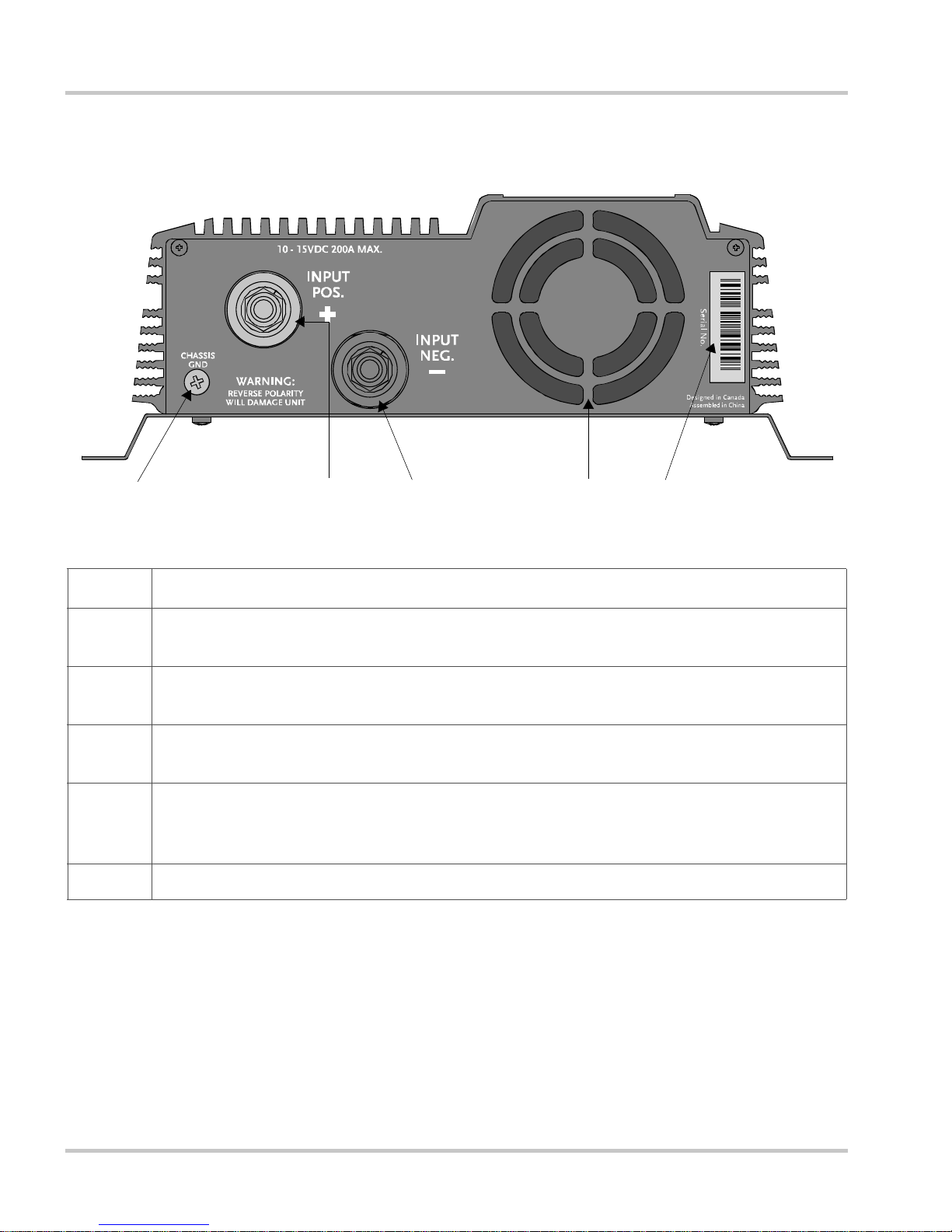
DC Panel
¨
Figure 2-2
Feature Description
1 Chassis Ground Screw connects to vehicle chassis, DC grounding bus or to en gine’s
2 Positive DC Cabling Terminal always connects to the cable connected to the posit ive
3 Negative DC Cabling T erminal always connects to the cable connected to the negat ive
4 Ventilation Opening must not be obstructed for the prope r operation of the inverte r. The
5 Serial num ber of your unit
DC Panel (XPower 1750 Plus shown)
negativ e bus .
terminal of the battery.
terminal of the battery.
openings on the bottom of the inverter (not shown) must also not be obstructed. When the
inverte r is mounted, the ventilation opening on the DC panel mu st not point up or down.
Ø
±
2–4 445-0145-01-01

3
Installation
Chapter 3 provides information on cables and fuses to
help you plan for your installation and provide
procedures for installing the XPower Plus.
Xantrex highly recommends that you read the entire
chapter before beginning the installation procedures so
that you can plan an installation that is suited to your
power needs.
Installation
R
Designing Your Installation
Before doing anything e lse, you need to determine how you are going to
use your XPower Plus, and then design a power system that will give you
maximum performance. The more thorough your planning, the better
your power needs will be met. In particular, you will need to:
• Be aware of installation codes
• Calculate your bat tery requirements
• Choose an effective charging syste m
• Choose an appropriat e loca tion
• Calculate the cable siz e for your XPower 1200 Plus or XPower 1750
Plus
• Select the correct fuses or circuit breakers
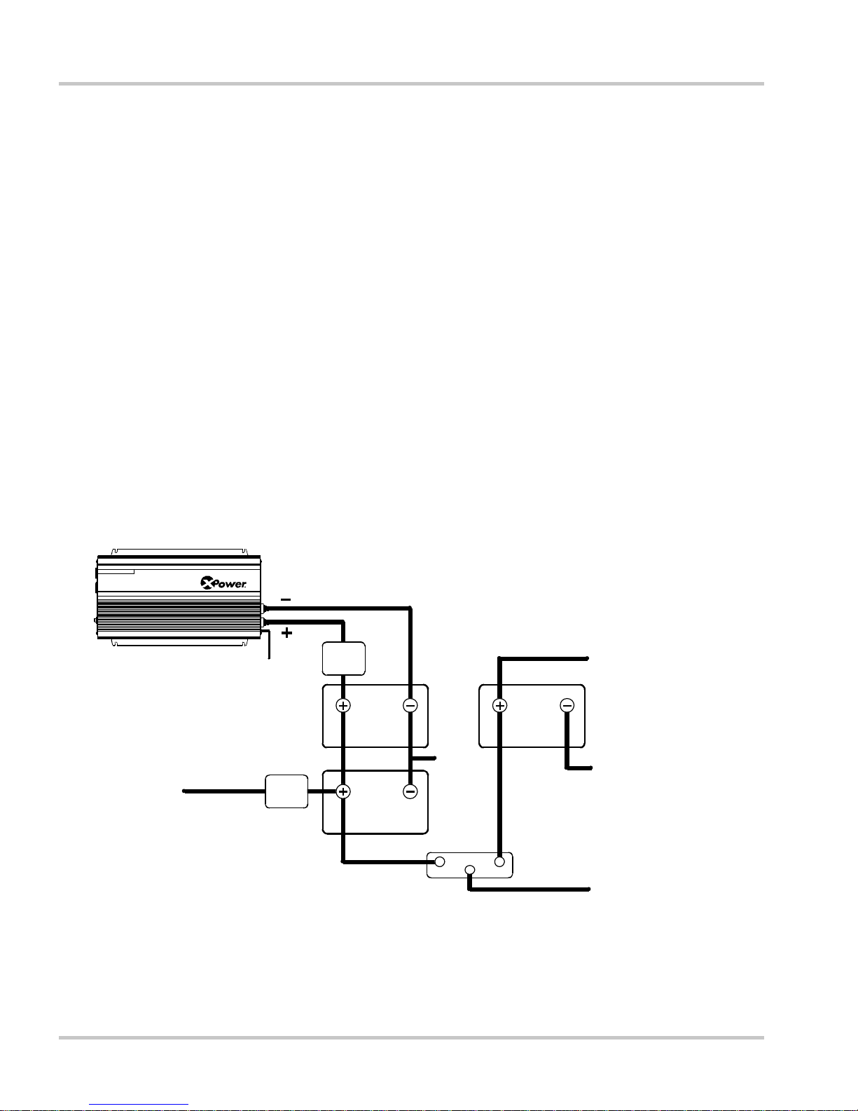
Study Figure 3-1, “Configuration for Normal Loads” on page 3–2 and
Figure 3 -2, “Configuration for Heavy Loads” on pa ge 3–3 for a n exa mple
of a setup for normal or heavy loads in a v ehi cle. When you have dec ided
upon your configurat ion, then you can calculate batter y requirements.
Figure 3-1
FUSE OR
CIRCUIT
BREAKER
DEEP-CYCLE
AUXILIARY
BATTERY
DEEP-CYCLE
AUXILIARY
BATTERY
TO DC
LOADS
GROUND TO
VEHICLE
CHASSIS
FUS E OR
CIRCUIT
BREAKER
Configuration for Normal Loads
GROUND TO
VEHICLE
CHASSIS
ISOLATOR
VEHICLE
STARTING
BATTERY
TO VEHICLE
GROUND TO
VEHICLE
CHASSIS
FROM ALTERNATO
OR CHARGER
3–2 445-0145-01-01
 Loading...