

XPF Series
Dual Output
35V 10A Powerflex
DC Power Supply
XPF 35-10
Operating Manual

About Xantrex
Xantrex Technology Inc. is a world-leading supplier of advanced power electronics and controls
with products from 50 watt mobile units to one MW utility-scale systems for wind, solar, batteries,
fuel cells, microturbines, and backup power applications in both grid-connected and stand-alone
systems. Xantrex products include inverters, battery chargers, programmable power supplies,
and variable speed drives that convert, supply, control, clean, and distribute electrical power.
Trademarks
XPF series is a trademark of Xantrex International. Xantrex is a registered trademark of Xantrex
International.
Other trademarks, registered trademarks, and product names are the property of their respective
owners and are used herein for identification purposes only.
Notice of Copyright
© Xantrex International. All rights reserved.
Disclaimer
UNLESS SPECIFICALLY AGREED TO IN WRITING, XANTREX TECHNOLOGY INC.
(“XANTREX”)
(a) MAKES NO WARRANTY AS TO THE ACCURACY, SUFFICIENCY OR SUITABILITY OF
ANY TECHNICAL OR OTHER INFORMATION PROVIDED IN ITS MANUALS OR OTHER
DOCUMENTATION.
(b) ASSUMES NO RESPONSIBILITY OR LIABILITY FOR LOSS OR DAMAGE, WHETHER
DIRECT, INDIRECT, CONSEQUENTIAL OR INCIDENTAL, WHICH MIGHT ARISE OUT
OF THE USE OF SUCH INFORMATION. THE USE OF ANY SUCH INFORMATION WILL
BE ENTIRELY AT THE USER’S RISK.
Date and Revision
February 2007 - Revision 2
Part Number
975-0106-01-02
Contact Information
Telephone: 1-800-733-5427 (toll free in North America)
1-858-450-0085 (direct)
Fax: 1-858-678-4482
Email: Customerservice@xantrex.com
Web: www.xantrex.com
1

Table of Contents
Specification 3
Safety 5
EMC 6
Installation 7
Connections 8
Operation 9
Maintenance 11
Calibration 12
Instructions en Francais
Sécurité 14
Installation 15
Connexions 16
Opération 16
Maintenance 18
Bedienungsanleitung auf Deutsch
Sicherheit 19
Installation 20
Anschlüsse 21
Betrieb 21
Wartung 24
Istruzioni in Italiano
Sicurezza 25
Installazione 26
Collegamento 27
Funzionamento 27
Manutenzione 30
Instrucciones en Español
Seguridad 31
Instalación 32
Conexiones 33
Funcionamiento 33
Mantenimiento 35
Warranty Information 36
2
OUTPUT SPECIFICATIONS
Voltage Range: 0V to 35V
Current Range: 0A to 10A
Power Range: Up to 175W
Output Voltage Setting: By coarse and fine controls.
Output Current Setting: By single logarithmic control.
Operating Mode: Constant voltage or constant current with automatic cross-over
Specification
provided that the power demanded stays within the power
envelope, see graph. Outside of this envelope the output becomes
unregulated.
Output Switch: Electronic. Preset voltage and current displayed when off.
Output Terminals: 4mm terminals on 19mm (0·75”) pitch. 15A max.
Sensing: Switchable between local and remote. Spring-loaded push
terminals for remote connection.
Output Impedance:
Output Protection: Forward protection by Over-Voltage Protection (OVP) trip;
OVP Range: 10% to 110% of maximum output voltage set by front panel
Line & Load Regulation: <0.01% of maximum output for a 10% line change;
Ripple & Noise
(20MHz bandwidth):
Transient Load Response: <2ms to within 100mV of set level for 90% load change.
Typically <5mΩ in constant voltage mode.
Typically >5kΩ in constant current mode (voltage limit at max).
maximum voltage that should be applied to the terminals is 50V.
Reverse protection by diode clamp for reverse currents up to 3A.
screwdriver adjustment.
<0.05% of maximum output for a 90% load change.
5mVrms max; typically <2mVrms, <20mV pk-pk, both outputs fully
loaded (7A @ 25V), CV mode.
Temperature Coefficient: Typically <100ppm/°C
Status Indication: Output on lamp.
Constant voltage mode lamp.
Constant current mode lamp.
Unregulated (power limit) lamp
Trip message on display.
3

METER SPECIFICATIONS
Meter Types: Dual 4 digit meters with 12.5mm (0.5") LEDs. Reading rate 4 Hz.
Meter Resolutions: 10mV, 10mA
Meter Accuracies: Voltage 0.2% of reading +/-1 digit,
GENERAL
AC Input: 110V-120V AC or 220V-230V AC ± 10%, 50/60Hz.
Power Consumption: 600VA max.
Operating Range: +5ºC to +40ºC, 20% TO 80% RH.
Current 0.5% of reading +/-1 digit
Installation Category II.
Storage Range:
Environmental: Indoor use at altitudes up to 2000m, Pollution Degree 2.
Safety: Complies with EN61010-1.
EMC: Complies with EN61326.
Size: 210 x 130 x 375mm (WxHxD) half rack width x 3U height.
Weight: 5kg
−40ºC to + 70ºC.
4
Safety
This power supply is a Safety Class I instrument according to IEC classification and has been
designed to meet the requirements of EN61010-1 (Safety Requirements for Electrical Equipment
for Measurement, Control and Laboratory Use). It is an Installation Category II instrument
intended for operation from a normal single phase supply.
This instrument has been tested in accordance with EN61010-1 and has been supplied in a safe
condition. This instruction manual contains some information and warnings which have to be
followed by the user to ensure safe operation and to retain the instrument in a safe condition.
This instrument has been designed for indoor use in a Pollution Degree 2 environment in the
temperature range 5°C to 40°C, 20% - 80% RH (non-condensing). It may occasionally be
subjected to temperatures between +5°C and –10°C without degradation of its safety. Do not
operate while condensation is present.
Use of this instrument in a manner not specified by these instructions may impair the safety
protection provided. Do not operate the instrument outside its rated supply voltages or
environmental range.
WARNING! THIS INSTRUMENT MUST BE EARTHED
Any interruption of the mains earth conductor inside or outside the instrument will make the
instrument dangerous. Intentional interruption is prohibited. The protective action must not be
negated by the use of an extension cord without a protective conductor.
When the instrument is connected to its supply, terminals may be live and opening the covers or
removal of parts (except those to which access can be gained by hand) is likely to expose live
parts. The apparatus shall be disconnected from all voltage sources before it is opened for any
adjustment, replacement, maintenance or repair. Capacitors inside the power supply may still be
charged even if the power supply has been disconnected from all voltage sources but will be
safely discharged about 10 minutes after switching off power.
Any adjustment, maintenance and repair of the opened instrument under voltage shall be avoided
as far as possible and, if inevitable, shall be carried out only by a skilled person who is aware of
the hazard involved.
If the instrument is clearly defective, has been subject to mechanical damage, excessive moisture
or chemical corrosion the safety protection may be impaired and the apparatus should be
withdrawn from use and returned for checking and repair.
Make sure that only fuses with the required rated current and of the specified type are used for
replacement. The use of makeshift fuses and the short-circuiting of fuse holders is prohibited.
Do not wet the instrument when cleaning it.
The following symbols are used on the instrument and in this manual:-
Earth (ground) terminal.
mains supply OFF.
l
mains supply ON.
alternating current (ac)
5

This instrument has been designed to meet the requirements of the EMC Directive 89/336/EEC.
Compliance was demonstrated by meeting the test limits of the following standards:
Emissions
EN61326 (1998) EMC product standard for Electrical Equipment for Measurement, Control and
Laboratory Use. Test limits used were:
a) Radiated: Class B
b) Conducted: Class B
c) Harmonics: EN61000-3-2 (2000) Class A; the instrument is Class A by product category.
Immunity
EN61326 (1998) EMC product standard for Electrical Equipment for Measurement, Control and
Laboratory Use.
Test methods, limits and performance achieved were:
a) EN61000-4-2 (1995) Electrostatic Discharge : 4kV air, 4kV contact, Performance A.
b) EN61000-4-3 (1997) Electromagnetic Field, 3V/m, 80% AM at 1kHz, Performance A.
EMC
c) EN61000-4-11 (1994) Voltage Interrupt, 1 cycle, 100%, Performance B.
d) EN61000-4-4 (1995) Fast Transient, 1kV peak (AC line), 0.5kV peak (DC Outputs),
Performance A.
e) EN61000-4-5 (1995) Surge, 0.5kV (line to line), 1kV (line to ground), Performance A.
f) EN61000-4-6 (1996) Conducted RF, 3V, 80% AM at 1kHz (AC line only; DC Output
connections <3m not tested), Performance A.
According to EN61326 the definitions of performance criteria are:
Performance criterion A: ‘During test normal performance within the specification limits’.
Performance criterion B: ‘During test, temporary degradation, or loss of function or
performance which is self-recovering’.
Performance criterion C: ‘During test, temporary degradation, or loss of function or
performance which requires operator intervention or system reset occurs.’
Where Performance B is stated it is because DC Output regulation may deviate beyond
Specification limits under the test conditions. However, the possible deviations are still small and
unlikely to be a problem in practice.
Note that if operation in a high RF field is unavoidable it is good practice to connect the PSU to
the target system using screened leads which have been passed (together) through an absorbing
ferrite sleeve fitted close to the PSU terminals.
Cautions
6
To ensure continued compliance with the EMC directive observe the following precautions:
a) after opening the case for any reason ensure that all signal and ground connections are
remade correctly and that case screws are correctly refitted and tightened.
b) In the event of part replacement becoming necessary, only use components of an identical
type, see the Service Manual.
E
(
)
(
)
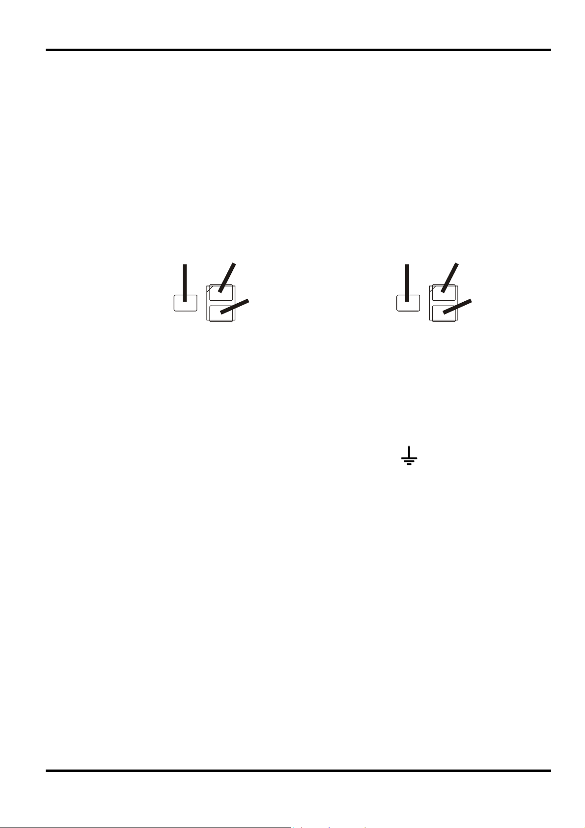
Mains Operating Voltage
Check that the instrument operating voltage marked on the rear panel is suitable for the local
supply. Should it be necessary to change the operating voltage, proceed as follows:
1. Ensure that the instrument is disconnected from the AC supply.
2. Remove the 6 screws holding the case upper and lift off the cover.
3. Change the plug-in connections between the transformer and main board following the
diagram below:
230V OPERATION 115V OPERATION
(VIEW FROM ABOVE) (VIEW FROM ABOVE)
Installation
4. Re-assemble in the reverse order.
5. To comply with safety standard requirements the operating voltage on the rear panel must
Mains Lead
When a three core mains lead with bare ends is provided this should be connected as follows:
When fitting a fused plug a 5 amp fuse should be fitted inside the plug. As the colours of the
wires in the mains lead of this apparatus may not correspond with the coloured markings
identifying the terminals in your plug proceed as follows:
RED BROW N
PP
PARK
be changed to clearly show the new voltage setting.
BROWN - MAINS LIVE
BLUE - MAINS NEUTRAL
GREEN/YELLOW - EARTH Safety Earth Symbol
BROW N RED
L
N
BLUE BLU
PARK
L
N
The wire which is coloured green-and-yellow must be connected to the terminal in the plug which
is marked by the letter E or by the safety earth symbol shown above or coloured green or greenand-yellow.
The wire which is coloured blue must be connected to the terminal which is marked with the letter
N or coloured black.
The wire which is coloured brown must be connected to the terminal which is marked with the
letter L or coloured red.
WARNING! THIS INSTRUMENT MUST BE EARTHED.
Any interruption of the mains earth conductor inside or outside the instrument will make the
instrument dangerous. Intentional interruption is prohibited.
Mounting
This instrument is suitable both for bench use and rack mounting. It is delivered with feet for
bench mounting. The front feet include a tilt mechanism for optimal panel angle.
7

Connections
All connections are made from the front panel.
The load should be connected to the positive (red) and negative (black) terminals marked
OUTPUT. The OUTPUT terminals are rated at 30A.
Remote sense connections to the load, if required, are made from the positive (+) and
negative (−) SENSE terminals. Switch the LOCAL/REMOTE switch to REMOTE when remote
sensing is required. Switch back to LOCAL when remote sensing is not in use.
The terminal marked
is connected to the chassis and safety earth ground.
8
The operation of both outputs is identical; the following description applies to both.
Setting Up the Output
With the POWER switch on (l) and the OUTPUT switch off the output voltage and current limit
can be accurately preset using the VOLTAGE and CURRENT controls; the upper meter shows
the set voltage and the lower meter shows the set maximum current.
When the OUTPUT switch is switched on, the OUTPUT ON lamp and the CV (constant voltage)
lamp light; the upper meter continues to show the set voltage but the lower meter now shows the
actual load current.
Constant Voltage
The output voltage is adjusted using the coarse and fine VOLTAGE control; the CURRENT
control sets the maximum current that can be supplied.
The CV lamp lights to show constant voltage mode.
Constant Current
If the load resistance is low enough such that, at the output voltage set, a current greater than the
current limit setting would flow, the power supply will automatically move into constant current
operation. The current output is adjusted by the CURRENT control and the VOLTAGE controls
set the maximum voltage that can be generated.
Operation
The CI lamp lights to show constant current mode.
Instantaneous Current Output
The current limit control can be set to limit the continuous output current to levels down to 10mA.
However, in common with all precision bench power supplies, a capacitor is connected across the
output to maintain stability and good transient response. This capacitor charges to the output
voltage and short-circuiting of the output will produce a current pulse as the capacitor discharges
which is independent of the current limit setting.
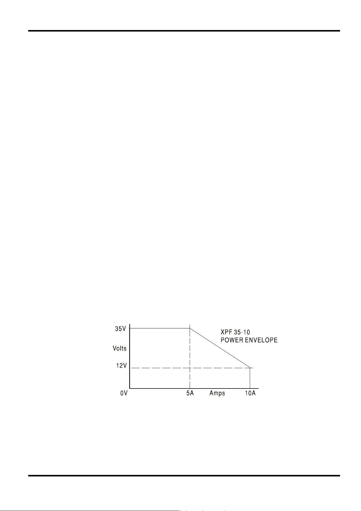
Power Limit
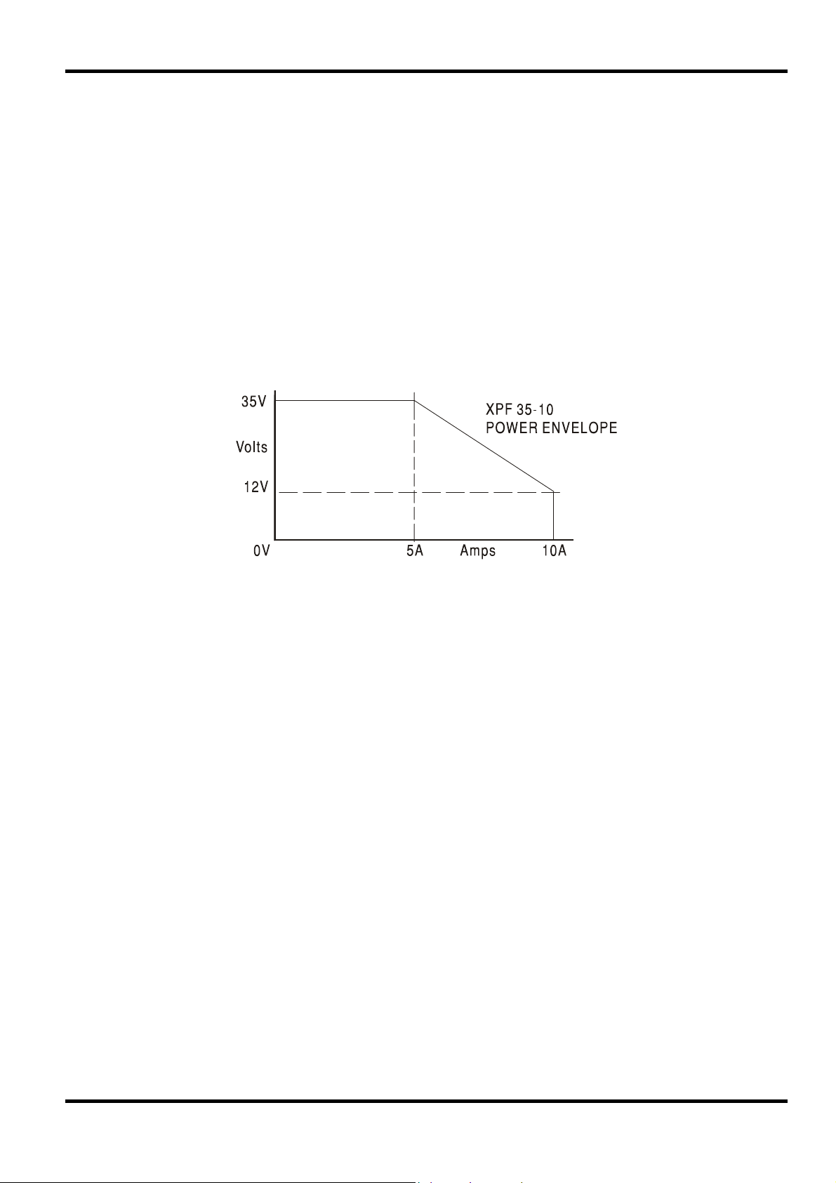
The maximum output at different voltage settings is limited by the power envelope illustrated
below:
The power envelope is set to give 35V/5A and 12V/10A under all supply conditions (both outputs
loaded); at lower output voltages the output power is restricted by the 10A current maximum.
When the power limit is exceeded, the status indication will change from CV or CI to UNREG. For
example, if the supply is set to 14V, with the current limit at maximum, and is connected to a
3.5Ohm load, 4Amps will flow and the supply will be in CV mode. As the voltage across the load
is increased, the power into the load increases until, at about 25V, the power limit is exceeded
and the supply changes from CV to UNREG.
9

Connection to the Load
The load should be connected to the positive (red) and negative (black) OUTPUT terminals. Both
are fully floating and either can be connected to ground.
Remote Sensing
The unit has a very low output impedance, but this is inevitably increased by the resistance of the
connecting leads. At high currents this can result in significant differences between the indicated
source voltage and the actual load voltage (two 20mΩ connecting leads will drop 0.2V at 5 Amps,
for instance). This problem can be minimised by using short, thick, connecting leads, but where
necessary it can be completely overcome by using the remote sense facility.
This requires the sense terminals to be connected to the output at the load instead of at the
source; insert wires into the spring-loaded SENSE terminals and connect directly to the load.
Switch the LOCAL/REMOTE switch to REMOTE. To avoid instability and transient response
problems, care must be taken to ensure good coupling between each output and sense lead. This
can be done either by twisting the leads together or by using coaxially screened cable (sense
through the inner). An electrolytic capacitor directly across the load connection point may also be
beneficial.
The voltage drop in each output lead must not exceed 0.5 Volts.
Switch the LOCAL/REMOTE switch back to LOCAL when remote sensing is not in use.
Series or Parallel connection with other units
The outputs of the power supply are fully floating and may be used in series with other power
supply units to generate high DC voltages up to 300V DC.
WARNING! Such voltages are exceedingly hazardous and great care should be taken to shield
the output terminals for such use. On no account should the output terminals be touched when
the unit is switched on under such use. All connections to the terminals must be made with the
power switched off on all units.
It should be noted that the unit can only source current and cannot sink it, thus units cannot be
series connected in anti-phase.
The unit can be connected in parallel with others to produce higher currents. Where several units
are connected in parallel, the output voltage will be equal to that of the unit with the highest output
voltage setting until the current drawn exceeds its current limit setting, upon which the output will
fall to that of the next highest setting, and so on. In constant current mode, units can be
connected in parallel to provide a current equal to the sum of the current limit settings.
Note that the output terminals are rated at 30A maximum; if two or more outputs are operated in
parallel to source higher currents than this the junction should be made at a separate point, not
one of the terminals.
Protection
Overvoltage protection (OVP) is fully variable within the range 10% to 110% of the supply's
maximum output level. The OVP limit is set via the screwdriver adjustable SET OVP preset
potentiometer, accessible through a hole in the front panel. Rotating the preset clockwise
increases the limit, which can be read directly on the user display by pressing the button beneath
the preset. If the voltage on the output exceeds the set OVP for any reason, including an
externally forced voltage, the output will be tripped off.
10
The output will also be tripped off if an attempt is made to draw power from the sense wires.
When the output is tripped the OUTPUT lamp will still be ON but the displays will show ‘OP trip’
and the UNREG lamp will also light. Turn the output off; the trip message should be replaced with
the normal preset V and I readings. When the cause of the trip has been removed the output can
be switched on again.

Even with the output off the load is still connected to the power supply output stage. Do not apply
external voltages in excess of 50V to the power supply terminals or damage may result.
The output is protected from reverse voltages by a diode; the continuous reverse current must not
exceed 3 Amps, although transients can be much higher.
Ventilation
The power supply is very efficient but nevertheless can generate significant heat at full power.
The supply relies on convection cooling only and it is therefore important that ventilation is never
restricted if performance and safety are to be maintained. If the supply is mounted in a restricted
space, eg. a 19 inch rack, then adequate ventilation must be ensured by using, for example, a fan
tray.
The Manufacturers or their agents overseas will provide repair for any unit developing a fault.
Where owner wish to undertake their own maintenance work, this should only be done by skilled
personnel in conjunction with the service manual which may be purchased directly from the
Manufacturers or their agents overseas.
Fuse
Maintenance
The correct fuse type for both AC supply ranges is:
Make sure that only fuses of the required rated current and specified type are used for
replacement. The use of makeshift fuses and the short-circuiting of fuse-holders is prohibited.
To replace the fuse, first disconnect the instrument from the AC supply. Remove the 6 cover
securing screws and lift off the cover. Replace the fuse with one of the correct type and refit the
cover.
Note that the main function of the fuse is to make the instrument safe and limit damage in the
event of failure of one of the switching devices. If a fuse fails it is therefore very likely that the
replacement will also blow, because the supply has developed a fault; in such circumstances the
instrument will need to be returned to the manufacturer for service.
Cleaning
If the PSU requires cleaning use a cloth that is only lightly dampened with water or a mild
detergent. Polish the display window with a soft dry cloth.
WARNING! TO AVOID ELECTRIC SHOCK, OR DAMAGE TO THE PSU, NEVER ALLOW
WATER TO GET INSIDE THE CASE. TO AVOID DAMAGE TO THE CASE OR DISPLAY
WINDOW NEVER CLEAN WITH SOLVENTS.
10 Amp 250V HBC time-lag, 5 x 20mm.
11

Allow at least 5 minutes warm-up before commencing calibration.
Access to Calibration Adjustments
All adjustments are on the control board, which is mounted above the main (power) board, except
where stated. To gain access to the board it is necessary to remove the top cover.
WARNING!
When the instrument is connected to its supply the removal of covers is likely to expose live parts.
The instrument should be disconnected from all voltage sources before it is opened for any
adjustment, replacement, maintenance or repair. Capacitors inside the power supply may still be
charged even if the power supply has been disconnected from all voltage sources but will be
safely discharged about 5 minutes after switching off power.
Any adjustment, maintenance and repair of the opened instrument under voltage shall be avoided
as far as possible and, if inevitable, shall be carried out only by a skilled person who is aware of
the hazard involved.
Remove the 6 side screws to release the top cover.
Component adjustment references are given as Channel A/ Channel B, e.g. VR5/VR105;
Channel A is the left-hand output (Output 1).
Equipment Required
Calibration
5½ digit multimeter with better than 0·05% DC Volts accuracy and better than 0·1% DC Amps
accuracy (to 10A); alternatively use a precision shunt for current measurement.
Rheostat or other high power load arrangement to provide up to 5A load at 35V and 10A at 12V.
A small switch, 15kΩ resistor and diode.
12

Voltage Calibration
Connect DMM, set to Volts, across output. Set voltage controls to minimum and current control to
maximum. Switch output ON and check for a reading of 00·00V ± 0·01V on display and DMM.
Set voltage controls to maximum. Adjust VR16/VR116 (maximum output volts) for a reading of
35·30V ± 0·02V on the DMM. Adjust VR2/VR102 (preset volts) until display matches DMM.
Connect rheostat to output and adjust for nominally 4A at maximum output voltage. Reduce
current limit (current control anticlockwise) until output just enters CI mode. Adjust VR8/VR108
(measured volts) until display matches DMM reading.
Current Calibration
Connect DMM, set to 20A range, in series with rheostat set to about 1Ω. With output OFF set
voltage controls to maximum and current control to 0·10A. Switch output ON and adjust
VR1/VR101 for 0·10A ± ·01A on DMM.
Set voltage controls to 12V, current control to maximum; supply should be in CI mode. Adjust
VR6/VR106 (maximum output current) for 10·20A ± ·02A on DMM.
Switch output OFF. Adjust VR3/VR103 (preset current) until display matches maximum output set
by VR6/VR106 above.
Increase rheostat resistance until unit enters CV mode. Adjust VR1/VR101 (measured current) on
Main board until display matches DMM reading.
Set Power Limit
Switch output OFF, set voltage control to 12·1V, current control to maximum. Switch output ON,
set rheostat so that current is 10·0A (ensure CV mode is maintained). Adjust VR5/VR105 (power
limit) until the UNREG l.e.d. just lights; back off VR5/VR105 until CV is lit and UNREG is off.
Set voltage controls to maximum and check unit enters UNREG mode. Increase rheostat
resistance until unit enters CV mode again; check meter reads between 5A and 6·2A.
Remove load.
OVP Calibration
Set voltage controls to minimum, current control to maximum. Set VR7/VR107 fully anticlockwise. Switch output ON. Press OVP button and set front panel OVP control (screwdriver
adjustment) for a display of 20·00V; release OVP button.
Set output voltage to 20·00V and adjust VR7/VR107 (OVP calibrate) slowly anticlockwise until
OVP is tripped (display reads TRIP). Turn output OFF and reset front panel OVP control fully
clockwise.
Voltage Regulation
Remove the link between the – OUTPUT and – SENSE terminals and fit a diode, anode to
– SENSE and cathode to –OUTPUT; connect a small switch across the diode. Leave the link in
place between + OUTPUT and + SENSE and connect a 15kΩ resistor between + OUTPUT and
– SENSE. Connect the DMM, set to Volts, between the sense terminals.
Close the switch, switch the output ON and set the output to 18·xxxx on the DMM; note the exact
reading. Open the switch and adjust VR4/VR104 for exactly the same reading; close the switch
again and check the reading is unchanged.
Remove the diode, resistor and switch and refit the sense link.
13

Sécurité
Cet instrument est de Classe de sécurité 1 suivant la classification IEC et il a été construit pour
satisfaire aux impératifs EN61010-1 (impératifs de sécurité pour le matériel électrique en vue de
mesure, commande et utilisation en laboratoire). Il s'agit d'un instrument d'installation Catégorie II
devant être exploité depuis une alimentation monophasée habituelle.
Cet instrument a été soumis à des essais conformément à EN61010-1 et il a été fourni en tout
état de sécurité. Ce manuel d'instructions contient des informations et avertissements qui doivent
être suivis par l'utilisateur afin d'assurer un fonctionnement de toute sécurité et de conserver
l'instrument dans un état de bonne sécurité.
Cet instrument a été conçu pour être utilisé en interne dans un environnement de pollution
Degré 2, plage de températures 5°C à 40°C, 20% - 80% HR (sans condensation). Il peut être
soumis de temps à autre à des températures comprises entre +5°C et –10°C sans dégradation
de sa sécurité. Ne pas l'utiliser lorsqu'il y a de la condensation.
Toute utilisation de cet instrument de manière non spécifiée par ces instructions risque d'affecter
la protection de sécurité conférée. Ne pas utiliser l'instrument à l'extérieur des tensions
d'alimentation nominales ou de la gamme des conditions ambiantes spécifiées.
AVERTISSEMENT! CET INSTRUMENT DOIT ETRE RELIE A LA TERRE
Toute interruption du conducteur de terre secteur à l'intérieur ou à l'extérieur de l'instrument
rendra l'instrument dangereux. Il est absolument interdit d'effectuer une interruption à dessein. Ne
pas utiliser de cordon de prolongation sans conducteur de protection, car ceci annulerait sa
capacité de protection.
Lorsque l'instrument est relié au secteur, il est possible que les bornes soient sous tension et par
suite, l'ouverture des couvercles ou la dépose de pièces (à l'exception de celles auxquelles on
peut accéder manuellement) risque de mettre à découvert des pièces sous tension. Il faut
débrancher ke cordon secteur de l'appareil avant de l'ouvrir pour effectuer des réglages,
remplacements, travaux d'entretien ou de réparations. Les condensateurs qui se trouvent dans le
bloc d'alimentation risquent de rester chargés, même si le bloc d'alimentation a été déconnecté
de toutes les sources de tension, mais ils se déchargeront en toute sécurité environ 10 minutes
après extinction de l'alimentation.
Eviter dans la mesure du possible d'effectuer des réglages, travaux de réparations ou d'entretien
lorsque l'instrument ouvert est branché au secteur, mais si c'est absolument nécessaire, seul un
technicien compétent au courant des risques encourus doit effectuer ce genre de travaux.
S'il est évident que l'instrument est défectueux, qu'il a été soumis à des dégâts mécaniques, à
une humidité excessive ou à une corrosion chimique, la protection de sécurité sera amoindrie et il
faut retirer l'appareil, afin qu'il ne soit pas utilisé, et le renvoyer en vue de vérifications et de
réparations.
Remplacer les fusibles uniquement par des fusibles d'intensité nominale requise et de type
spécifié. Il est interdit d'utiliser des fusibles bricolés et de court-circuiter des porte-fusibles.
Eviter de mouiller l'instrument lors de son nettoyage.
Les symboles suivants se trouvent sur l'instrument, ainsi que dans ce manuel.
Borne de terre (masse)
14
l
alimentation secteur ON (allumee)
alimentation secteur OFF (eteinte)
courant alternatif (c.a.)

Tension d’utilisation secteur
Vérifier que la tension opérationnelle de l'instrument indiquée sur le panneau arrière est
appropriée pour l'alimentation locale. S'il s'avère nécessaire de modifier la tension opérationnelle,
procéder de la manière décrite ci-dessous:
1. S'assurer que l'instrument est débranché de l'alimentation c.a.
2. Retirer les 6 vis qui maintiennent la partie supérieure du boîtier et démonter celle-ci en la
soulevant.
3. Changer les connexions entre le transformateur et la carte principale à l’aide des
illustrations suivantes :
FONCTIONNEMENT A 230V FONCTIONNEMENT A 115V
(VUE DE DESSUS) (VUE DE DESSUS)
Installation
4. Effectuer le remontage dans l'ordre inverse.
5. Afin de respecter les impératifs des normes de sécurité, il faut changer la tension de
fonctionnement marquée sur le panneau arrière pour indiquer clairement le nouveau
réglage de tension.
Câble secteur
Relier de la manière suivante tout câble secteur à trois conducteurs à fils nus:
MARRON - SECTEUR SOUS TENSION
BLEU - SECTEUR NEUTRE
VERT/JAUNE - TERRE Symbole Terre de protection
Lors du montage d'une fiche à fusible, mettre un fusible de 5 A à l'intérieur de la fiche. Il est
possible que les couleurs des fils du câble secteur de cet appareil ne correspondent pas aux
marques de couleur d'identification des bornes de la fiche, et par suite, il est recommandé de
procéder de la manière suivante:
ROUGE MARRON
PP
(PARK) (PARK)
MARRON ROUGE
LL
NN
BLEU BLEU
Relier le fil vert et jaune à la borne de la fiche désignée par la lettre E ou par le symbole Terre de
protection indiqué ci-dessus, ou qui est en vert, ou en vert et jaune.
Relier le fil bleu à la borne désignée par la lettre N, ou qui est en noir.
Relier le fil marron à la borne désignée par la lettre L, ou qui est en rouge.
AVERTISSEMENT! CET INSTRUMENT DOIT ETRE RELIE A LA TERRE
Toute interruption du conducteur de terre secteur à l'intérieur ou à l'extérieur de l'instrument
rendra l'instrument dangereux. Il est absolument interdit d'effectuer une interruption à dessein.
Montage
Cet instrument est approprié pour être monté sur établi ou sur baie. Il est fourni avec des pieds
en vue de montage sur établi. Les pieds avant comprennent un mécanisme d’inclinaison en vue
d’obtention d’un angle de panneau optimum.
15

Connexions
Toutes les connexions sont effectuées au panneau avant.
Relier la charge aux bornes positive (rouge) et négative (noire) marquées OUTPUT (Sortie). Les
bornes de sortie ont une intensité nominale de 30 A.
Effectuer des connexions de télédétection à la charge, le cas échéant, des bornes de détection
(SENSE) positive (+) et négative (−). Placer le commutateur LOCAL/REMOTE en position
REMOTE lorsque la détection distante est requise. Placer le commutateur en position LOCAL
lorsque cette détection distante n’est pas utilisée.
La borne désignée
Le fonctionnement des deux sorties est identique; la description qui suit s’applique aux deux.
est reliée au châssis et à la terre de protection.
Réglage de la sortie
Une fois l’interrupteur d’alimentation POWER sur (l) et le commutateur de sortie OUTPUT en
position d’arrêt, utiliser les commandes de VOLTAGE (tension) et de CURRENT (courant) pour
régler avec précision la limite de courant et la tension de sortie ; l'appareil de mesure supérieur
indique la tension réglée et l'appareil inférieur le courant maximum réglé.
Lorsque le commutateur de sortie est en position de marche, les voyants OUTPUT ON (sortie
activée) et CV (tension constante) sont allumés; l’appareil de mesure supérieur continue à
indiquer la tension réglée, mais l’appareil inférieur indique maintenant le courant de charge
véritable.
Tension constante
Les commandes de VOLTAGE approximative et de précision permettent de régler la tension de
sortie; la commande de CURRENT règle le courant maximum qui peut être fourni.
Le voyant CV s’allume pour indiquer le mode de tension constante.
Courant constant
Si la résistance de charge est suffisamment basse pour permettre à un courant supérieur à celui
du réglage de limite de courant de passer au niveau de tension de sortie réglé, l'alimentation
passera automatiquement en mode courant constant. La commande de CURRENT permet de
régler la sortie de courant et les commandes de VOLTAGE règlent la tension maximale qui peut
être générée. Le voyant CI s’allume pour indiquer le mode de courant constant.
Sortie de courant instantanée
On peut régler la commande de limite de courant pour limiter le courant de sortie continu à des
niveaux aussi bas que 10 mA. Toutefois, ainsi que c'est le cas de toutes les alimentations de
précision sur établi, un condensateur est relié entre les bornes de sortie, afin de maintenir la
stabilité, ainsi qu'une bonne réponse transitoire. Ce condensateur se charge jusqu'à la tension de
sortie, et le court-circuitage de la sortie produit une impulsion de courant lors du déchargement
du condensateur indépendamment du réglage de limite de courant.
Limite de puissance
La sortie maximale à différents réglages de tension est limitée par l’enveloppe de puissance
illustrée ci-dessous:
Opération
16

L’enveloppe de puissance est réglée pour donner 35 V/5 A et 12 V/10 A à toutes les conditions
d’alimentation (les deux sorties chargées); à de plus basses tensions de sortie, la puissance de
sortie est restreinte par le courant de 10 A maximum.
Si la limite de puissance est dépassée, l’indication de l’état passe de CV ou de CI à UNREG.
Ainsi, par exemple, si l’alimentation est réglée sur 14 V, limite de courant au maximum, et qu’elle
est reliée à une charge de 3,5 Ohm, un courant de 4 A passera et l’alimentation sera en mode
CV. Au fur et à mesure de l’augmentation de la tension dans la charge, il se produit un
accroissement de la puissance dans la charge, jusqu’à ce qu’à environ 25 V un dépassement de
la limite de puissance survienne et que l’alimentation passe du mode CV au mode UNREG.
Connexion à la charge
Relier la charge aux bornes de sortie positive (rouge) et négative (noire). Les deux bornes sont
entièrement flottantes et il est possible de relier chacune à la terre.
Télédétection
Le bloc a une impédance de sortie très réduite, mais la résistance des câbles de raccordement
l'augmente automatiquement. En cas de courants élevés, ceci peut entraîner des différences
importantes entre la tension de source indiquée et la tension de charge véritable (par exemple,
deux câbles de raccordement de 20 mΩ entraîneront une chute de 0,2 V à une intensité de 5A). Il
est possible de réduire ce problème au minimum au moyen de câbles de raccordement courts et
épais et, le cas échéant, le résoudre entièrement au moyen de l'option de télédétection.
Ceci nécessite la connexion des bornes de détection à la sortie de la charge plutôt qu'à la
source ; insérer les fils dans les bornes à ressort SENSE et connecter directement à la charge.
Placer le commutateur LOCAL/REMOTE en position REMOTE. S'assurer qu'il y a un bon
couplage entre chaque fil de sortie et fil de détection pour éviter tout problème d'instabilité et de
réponse transitoire. On peut y parvenir soit par torsion des fils soit par utilisation de câble blindé
coaxialement (détection par le conducteur interne). Il peut s'avérer utile de relier directement un
condensateur électrolytique au point de connexion de charge.
La chute de tension de chaque fil de sortie ne doit pas dépasser 0,5 V.
Placer le commutateur LOCAL/REMOTE en position LOCAL lorsque la détection distante n’est
pas utilisée.
Connexion en série ou en parallèle avec d’autres appareils
Les sorties de l’alimentation sont entièrement isolées de la terre et peuvent être utilisées en série
avec d’autres blocs d’alimentation afin de produire des tensions c.c. jusqu’à 300 V c.c.
AVERTISSEMENT! Des tensions de ce genre sont extrêmement dangereuses et il faut prendre
toutes les précautions d’usage pour protéger les bornes de sortie en conséquence. Ne jamais
toucher les bornes de sortie lorsque le bloc est allumé pour ces applications. Toutes les
connexions des bornes doivent être effectuées lorsque tous les blocs sont éteints. Il faut noter
que le bloc peut uniquement recevoir du courant, mais non le consommer, de sorte qu’il n’est pas
possible de mettre en opposition de phase les blocs reliés en série.
Il est possible de relier le bloc en parallèle avec d’autres afin de produire des courants de haute
intensité. Lorsque plusieurs blocs sont reliés en parallèle, la tension de sortie doit être égale à
celle du bloc de réglage de tension de sortie le plus élevé, jusqu’à ce que le courant consommé
dépasse le réglage de limite de courant, auquel cas la sortie descend à celle du réglage le plus
haut suivant, etc. En mode de courant constant, les blocs peuvent être reliés en parallèle, afin de
donner un courant égal à la somme des réglages de limite de courant.
Il faut noter que l’intensité nominale des bornes de sortie est de 30 A maximum; en cas
d’exploitation de deux sorties ou plus en parallèle avec des courants de source supérieurs, il faut
effectuer cette jonction en un point séparé, mais non à une des bornes.
Protection
La protection de surtension (OVP) est entièrement variable dans la gamme 10% à 110% du
niveau de sortie maximum de l’alimentation. La limite OVP est réglée par le potentiomètre
préréglé SET OVP, auquel on peut accéder par un orifice du panneau arrière et qui peut être
ajusté au moyen d’un tournevis. Faire tourner dans le sens des aiguilles d’une montre le
potentiomètre pour augmenter la limite, puis appuyer sur le bouton sous le potentiomètre pour lire
17

les valeurs directement sur l’affichage de l’utilisateur. Si, pour une raison quelconque, la tension
de sortie dépasse la tension de protection OVP préréglée, y compris la tension forcée de manière
externe, il se produira un déclenchement de la sortie. Il se produira également un déclenchement
de la sortie en cas de tentative de consommation de puissance depuis les câbles de détection.
Lors du déclenchement de la sortie, le voyant OUTPUT reste allumé, mais l’affichage indique ‘OP
trip’ et le voyant UNREG est alors également allumé. Eteindre la sortie au moyen du
commutateur
message de déclenchement. Après élimination de la cause du déclenchement, il est possible de
rallumer la sortie, au moyen du commutateur
La sortie éteinte, la charge est toujours reliée à l’étage de sortie de l’alimentation. Ne pas
appliquer de tensions externes supérieures à 50 V aux bornes d’alimentation, car ceci pourrait
entraîner des dégâts.
La sortie est protégée contre toute tension inverse par une diode; le courant inverse continu ne
doit pas dépasser 3 A, mais il est possible que des transitoires aient une intensité nettement
supérieure.
Ventilation
L’alimentation est très performante, mais elle peut toutefois générer beaucoup de chaleur à
puissance maximale. L’alimentation a besoin d’un refroidissement par convection uniquement et il
est donc important que la ventilation ne soit jamais réduite, afin d’assurer une bonne performance
et sécurité. Si l’alimentation est montée dans un espace réduit, par exemple baie de 19 pouces, il
faut prévoir une ventilation adéquate, par exemple au moyen d’un plateau de ventilateur.
; les valeurs habituelles préréglées V et I doivent maintenant remplacer le
.
Le Constructeur ou ses agents à l'étranger répareront tout bloc qui tombe en panne. Si le
propriétaire de l'appareil décide d'effectuer lui-même la maintenance, ceci doit uniquement être
effectué par un personnel spécialisé qui doit se référer au manuel d’entretien que l'on peut se
procurer directement auprès du Constructeur ou de ses agents à l'étranger.
Fusible
Type de fusible correct pour les deux gammes d’alimentation c.a.:
Uniquement remplacer les fusibles par des fusibles d'intensité nominale requise et de type
spécifié. Il est interdit d'utiliser des fusibles bricolés et de court-circuiter des porte-fusibles.
Pour remplacer un fusible, débrancher tout d’abord l’instrument de l’alimentation c.a. Enlever les
6 vis de fixation du couvercle, puis retirer le couvercle. Remplacer le fusible par un nouveau
fusible de type correct, puis remettre le couvercle.
Il faut noter que la fonction primordiale d’un fusible est d’assurer une protection de l’instrument et
de limiter les dégâts en cas de panne d’un des dispositifs de commutation. Si un fusible saute, il
est très probable que le nouveau fusible sautera également, étant donné que le problème
provient de l’alimentation; dans ce cas, renvoyer l’instrument au constructeur en vue de
réparations.
Nettoyage
S'il faut nettoyer le bloc d'alimentation, utiliser un chiffon légèrement imbibé d'eau ou d'un
détergent doux. Nettoyer le cadran d'affichage au moyen d'un chiffon sec et doux.
Maintenance
10 A 250 V action différée HBC, 5 x 20 mm.
18
AVERTISSEMENT! EMPECHER TOUTE INTRODUCTION D'EAU DANS LE BOITIER AFIN
D'EVITER TOUT CHOC ELECTRIQUE ET DEGATS AU BLOC D'ALIMENTATION. NE JAMAIS
UTILISER DE DISSOLVANTS POUR NETTOYER LE BLOC, AFIN D'EVITER
D'ENDOMMAGER LE BOITIER OU LE CADRAN D’AFFICHAGE.

Sicherheit
Dieses Gerät wurde nach der Sicherheitsklasse (Schutzart) I der IEC-Klassifikation und gemäß
den europäischen Vorschriften EN61010-1 (Sicherheitsvorschriften für elektrische Mess-, Steuer,
Regel- und Laboranlagen) entwickelt. Es handelt sich um ein Gerät der Installationskategorie II,
das für den Betrieb mit einer normalen einphasigen Versorgung vorgesehen ist.
Das Gerät wurde gemäß den Vorschriften EN61010-1 geprüft und wurde in sicherem Zustand
geliefert. Die vorliegende Anleitung enthält vom Benutzer zu beachtende Informationen und
Warnungen, die den sicheren Betrieb und den sicheren Zustand des Gerätes gewährleisten.
Dieses Gerät ist für den Betrieb in Innenräumen der Umgebungsklasse 2 , für einen
Temperaturbereich von 5° C bis 40° C und 20 - 80 % relative Feuchtigkeit (nicht kondensierend)
vorgesehen. Gelegentlich kann es Temperaturen zwischen +5° und –10°C ausgesetzt sein, ohne
dass seine Sicherheit dadurch beeinträchtigt wird. Betreiben Sie das Gerät jedoch auf keinen
Fall, solange Kondensation vorhanden ist.
Ein Einsatz dieses Gerätes in einer Weise, die für diese Anlage nicht vorgesehen ist, kann die
vorgesehene Sicherheit beeinträchtigen. Auf keinen Fall das Gerät außerhalb der angegebenen
Nennversorgungsspannungen oder Umgebungsbedingungen betreiben.
WARNUNG! - DIESES GERÄT MUSS GEERDET WERDEN!
Jede Unterbrechung des Netzschutzleiters innerhalb oder außerhalb des Gerätes macht das
Gerät gefährlich. Eine absichtliche Unterbrechung ist verboten. Die Schutzwirkung darf nicht
durch Verwendung eines Verlängerungskabels ohne Schutzleiter aufgehoben werden.
Ist das Gerät an die elektrische Versorgung angeschlossen, so können die Klemmen unter
Spannung stehen, was bedeutet, dass beim Entfernen von Verkleidungs- oder sonstigen Teilen
(mit Ausnahme der Teile, zu denen Zugang mit der Hand möglich ist) höchstwahrscheinlich
spannungsführende Teile bloßgelegt werden. Vor jeglichem Öffnen des Gerätes zu Nachstell-,
Auswechsel-, Wartungs- oder Reparaturzwecken, Gerät stets von sämtlichen Spannungsquellen
abklemmen. Kondensatoren in der Stromversorgung können auch noch nach Abschalten
sämtlicher Stromversorgung Spannung führen, sie entladen sich jedoch innerhalb von etwa 10
Minuten nach Spannungsabschaltung.
Jegliche Nachstellung, Wartung und Reparatur am geöffneten, unter Spannung stehenden Gerät,
ist nach Möglichkeit zu vermeiden. Falls unvermeidlich, sollten solche Arbeiten nur von
qualifiziertem Personal ausgeführt werden, das sich der Gefahren bewusst ist.
Ist das Gerät eindeutig fehlerbehaftet, bzw. wurde es mechanisch beschädigt, übermäßiger
Feuchtigkeit oder chemischer Korrosion ausgesetzt, so können die Schutzeinrichtungen
beeinträchtigt sein, weshalb das Gerät aus dem Verkehr zurückgezogen und zur Überprüfung
und Reparatur eingesandt werden sollte.
Sicherstellen, dass nur Sicherungen der vorgeschriebenen Stromstärke und des vorgesehenen
Typs als Ersatz verwendet werden. Provisorische “Sicherungen” und der Kurzschluss von
Sicherungshaltern ist verboten.
Beim Reinigen darauf achten, dass das Gerät nicht nass wird.
Am Gerät werden folgende Symbole verwendet:
Erdungsklemme
l
19
Netz ON (ein)
Netz OFF (aus)
Wechselstrom

Netzbetriebsspannung
Sicherstellen, dass die auf der Geräterückwand angegebene Betriebsspannung mit der
Versorgungsspannung am Ort übereinstimmt. Falls es erforderlich ist, die Betriebsspannung zu
ändern, wie folgt vorgehen:
1. Sicherstellen, dass das Gerät vom Wechselstromnetz getrennt ist.
2. Die 6 Schrauben entfernen, mit denen die obere Gehäusehälfte befestigt ist, und den
Deckel abheben.
3. Die Steckverbindungen zwischen dem Transformator und der Hauptleiterplatte der
folgenden Abbildung gemäß verändern:
230V BETRIEB 115V BETRIEB
(VON OBEN GESEHEN) (VON OBEN GESEHEN)
Installation
4. Gerät in umgekehrter Reihenfolge wieder zusammenbauen.
5. Die Sicherheitsvorschriften werden nur dann erfüllt, wenn auch die Angabe der
Netzkabel
Steht nur ein Netzkabel ohne Stecker zur Verfügung, so ist es wie folgt anzuschließen:
GRÜN/GELB - SCHUTZLEITER Schutzleitersymbol
Bei Steckern mit eingebauten Sicherungen sollte eine 5 Ampere-Sicherung verwendet werden.
Da die Farben der Netzkabeladern nicht unbedingt mit den Farbmarkierungen der Klemmen Ihres
Steckers übereinstimmen, ist wie folgt vorzugehen:
ROT BRAUN
PP
(PARKEN) (PARKEN)
Betriebsspannung auf der Geräterückwand geändert wird, so dass die neue
Spannungseinstellung deutlich angezeigt ist.
BRAUN - STROMFÜHRENDER LEITER
BLAU - NULLEITER
BRAUN ROT
LL
NN
BLAU BLAU
Die grün/gelbfarbene Ader ist an die mit E oder mit dem oben abgebildeten Schutzleitersymbol
markierte oder grün bzw. grün/gelbfarbene Steckerklemme anzuschließen.
Die blaue Ader ist an die mit N markierte oder schwarzfarbene Klemme anzuschließen.
Die braune Ader ist an die mit L markierte oder rotfarbene Klemme anzuschließen.
Jede Unterbrechung des Netzschutzleiters innerhalb oder außerhalb des Gerätes macht das
Gerät gefährlich. Eine absichtliche Unterbrechung ist verboten.
Aufstellung/Montage
Das Gerät eignet sich sowohl als Tischgerät als auch für den Gestelleinbau. Für die Aufstellung
als Tischgerät wird es mit Füßen geliefert. Die vorderen Füße sind mit einem Kippmechanismus
versehen, der eine optimale Winkeleinstellung ermöglicht.
20
WARNUNG! DIESES GERÄT MUSS GEERDET WERDEN!

Anschlüsse
Sämtliche Anschlüsse erfolgen von der Fronttafel aus.
Der Verbraucher sollte an die mit AUSGANG (OUTPUT) markierte positive (rote) und negative
(schwarze) Klemme angeschlossen werden. Die AUSGANGS-Klemmen sind für eine Stromstärke
von 30 A ausgelegt.
Istwert-Fernerfassungs-Anschlüsse zum Verbraucher erfolgen, falls erforderlich, über die
positive (+) und negative (−) Fernerfassungsklemme (SENSE). Den Fernbedienungsschalter
(LOCAL/REMOTE) auf Fernbedienung (REMOTE) stellen, wenn eine Istwert-Fernerfassung
gewünscht wird. Wenn die Istwert-Fernerfassung nicht benutzt wird, auf Ortsbedienung (LOCAL)
zurückstellen.
Die mit dem Symbol
verbunden.
Der Betrieb beider Ausgänge ist identisch. Die nachstehende Beschreibung gilt für beide.
gekennzeichnete Klemme ist mit dem Chassis und der Schutzerde
Einstellung des Ausgangs (Output)
Bei eingeschaltetem Netzschalter (l) und ausgeschaltetem Ausgang kann die Ausgangsspannung
und Strombegrenzung mit Hilfe der Spannungs- (VOLTAGE) und Stromregelknöpfe (CURRENT)
genau voreingestellt werden. Die obere Anzeige zeigt die Sollspannung und die untere Anzeige
den vorgegebenen maximalen Strom an.
Bei eingeschaltetem Ausgangsschalter leuchten die Lampen Ausgang Ein (OUTPUT ON) und
Konstante Spannung (CV) auf. Die obere Anzeige zeigt nach wie vor die Sollspannung an,
während die untere Anzeige jetzt den tatsächlichen Verbraucherstrom anzeigt.
Konstantspannung
Die Ausgangsspannung lässt sich mit dem Grob- und Feinregelknopf für Spannung (VOLTAGE)
einstellen. Mit dem Strom-Regelknopf (CURRENT) wird der maximal lieferbare Strom eingestellt.
Der konstante Spannungsmodus wird durch Aufleuchten der CV-Lampe angezeigt.
Konstantstrom
Betrieb
Ist der Verbraucherwiderstand niedrig genug, dass bei der eingestellten Ausgangsspannung ein
Strom fließen würde, der größer wäre als die Strombegrenzungseinstellung, schaltet die
Stromversorgung automatisch auf Konstantstrombetrieb. Der Stromausgang wird über die
Stromregelung eingestellt und mit den Spannungs-Regelknöpfen (VOLTAGE) wird die maximal
generierbare Spannung eingestellt. Die aufleuchtende CI-Lampe zeigt den Konstantstrommodus
an.
Augenblickswert der Stromabgabe
Der Ausgangsdauerstrom kann mit Hilfe des Strombegrenzungsreglers (CURRENT LIMIT) auf
einen Pegel bis minimal 1 mA begrenzt werden. Wie bei allen anderen
Präzisionsstromversorgungen in Tischgerätausführung ist jedoch auch bei diesem Gerät ein
Kondensator parallel zum Ausgang geschaltet, damit für Stabilität und ein gutes transientes
Lastverhalten gesorgt ist. Dieser Kondensator wird aufgeladen, bis er die Ausgangsspannung
erreicht. Bei Kurzschließung des Ausgangs wird ein kurzer Stromimpuls erzeugt, wenn sich der
Kondensator entlädt, welcher unabhängig vom eingestellten Stromgrenzwert ist.
21

Leistungsgrenze
Der maximale Ausgang bei unterschiedlichen Spannungseinstellungen wird durch die unten
abgebildete Leistungshüllkurve (power envelope) begrenzt:
Die Leistungshüllkurve ist so eingestellt, dass unter Versorgungsbedingungen (wenn beide
Ausgänge belastet sind) 35V/5A und 12V/10A abgegeben werden. Bei niedrigeren
Ausgangsspannungen wird die Ausgangsleistung durch den maximalen Strom von 10A begrenzt.
Beim Überschreiten der Leistungsgrenze verändert sich die Statusanzeige von DV oder CI auf
UNREG. Wird die Versorgung bei maximaler Strombegrenzung z. B. auf 14 V gestellt und ein 3,5
Ohm-Verbraucher angeschlossen, so fließt ein Strom von 4 Ampere und die Versorgung befindet
sich im CV-Modus. Mit zunehmender Spannung beim Verbraucher erhöht sich auch die Leistung
zum Verbraucher bis bei etwa 25 V die Stromgrenze überschritten wird und die Versorgung von
CV auf UNREG umschaltet.
Verbraucheranschluss
Der Verbraucher ist an die positive (rote) und negative (schwarze) Ausgangsklemme (OUTPUT)
anzuschließen. Bei beiden Anschlüssen handelt es sich um vollkommen potentialfreie, so dass
es egal ist, welcher der beiden Anschlüsse geerdet wird.
Istwert-Fernerfassung
Die Ausgangsimpedanz ist bei dieser Einheit sehr niedrig, wird aber zwangsläufig durch den
Widerstand der Verbindungsleitungen erhöht. Bei hohen Stromstärken können sich hieraus
erhebliche Unterschiede zwischen der angezeigten Quellenspannung und der tatsächlichen
Lastspannung ergeben (bei zwei 20-mΩ-Anschlussleitungen ergibt sich beispielsweise ein
Spannungsabfall von 0,2V bei 5A). Dieses Problem kann durch die Verwendung einer kurzen
Verbindungsleitung mit großer Drahtstärke minimiert und, falls erforderlich, durch die Verwendung
der Einrichtung zur Istwert-Fernerfassung sogar ganz ausgeschaltet werden.
Zu diesem Zweck müssen die SENSE-Klemmen mit dem Ausgang des Verbrauchers statt mit
dem Ausgang der Quelle verbunden werden. Die Leitungen werden in die federbelasteten
SENSE-Klemmen eingeführt und direkt an den Verbraucher angeschlossen. Der
Fernbedienungsschalter (LOCAL/REMOTE) wird auf Fernbedienung (REMOTE) gestellt. Um
Probleme bezüglich der Stabilität und des Einschwingverhaltens zu vermeiden, ist sorgfältig
darauf zu achten, dass eine gute Kopplung zwischen dem jeweiligen Ausgang und der
Abtastleitung gegeben ist. Dies lässt sich auf zweierlei Arten erreichen: entweder indem die
Leitungen miteinander verdrillt werden oder indem ein koaxial geschirmtes Kabel (Abtastung über
den Innerleiter) verwendet wird. Auch ein Elektrolytkondensator direkt am Lastanschlusspunkt
kann hier von Nutzen sein.
22
Der Spannungsabfall darf bei keiner Ausgangsleitung mehr als 0.5 Volt betragen.
Wenn die Istwert-Fernerfassung nicht benutzt wird, ist der Fernbedienungsschalter
(LOCAL/REMOTE) auf Ortsbedienung (LOCAL) zurückzustellen.

Reihen- und Parallelschaltung mit anderen Geräten
Da die Ausgänge des Netzteils vollständig potentialfrei sind, können sie mit anderen Netzgeräten
zur Erzeugung hoher Gleichspannungen bis maximal 300V in Reihe geschaltet werden.
WARNUNG! Spannungen in dieser Größenordnung sind überaus gefährlich. Bei einer solchen
Einsatzweise sollten die Ausgangsklemmen mit größter Sorgfalt abgeschirmt werden. Unter
diesen Bedingungen dürfen die Ausgangsklemmen keinesfalls berührt werden, wenn das Gerät
eingeschaltet ist. Wann immer Verbindungen mit den Klemmen hergestellt werden, müssen
sämtliche Geräte ausgeschaltet sein.
Zu beachten ist dabei, dass das Gerät ausschließlich stromliefernd, nicht aber stromziehend
arbeiten kann, und dass die Geräte daher nicht gegenphasig in Reihe geschaltet werden können.
Das Gerät kann zur Erzeugung einer höheren Stromabgabe mit anderen Geräten parallel zu
diesen geschaltet werden. Wenn mehrere Geräte parallel geschaltet werden, entspricht die
Ausgangsspannung der Ausgangsspannung des Gerätes, bei dem der Einstellwert für die
Ausgangsspannung am höchsten ist, bis die Stromaufnahme den bei diesem Gerät eingestellten
Grenzwert überschreitet, woraufhin der Ausgang auf die zweithöchste Einstellung abfällt, und so
weiter. Im Konstantstrombetrieb können Geräte parallel geschaltet werden, wodurch sich eine
Stromabgabe erreichen lässt, die der Summe der Einstellwerte für die Strombegrenzung
entspricht.
Zu beachten ist, dass die Ausgangsklemmen für maximal 30 A vorgesehen sind. Werden zwei
oder mehr Ausgänge parallel betrieben, um höhere Ströme als diesen zu liefern, so sollte die
Verbindung an einer getrennten Stelle vorgenommen werden, nicht an einer der Klemmen.
Überspannungsschutz
Der Überspannungsschutz lässt sich im Bereich 10 % bis 110 % der maximalen Ausgangsstufe
der Stromversorgung variieren. Die Überspannungsschutzgrenze wird über die mit dem
Schraubendreher verstellbare und mit SET OVP bezeichnete Schraube des voreingestellten
Potentiometers eingestellt, die über ein entsprechendes Loch in der Fronttafel zugänglich ist.
Durch Drehung im Uhrzeigersinn wird die Grenze erhöht, die sich durch Drücken der Taste unter
“Preset” (Voreinstellung) über die Benutzeranzeige direkt ablesen lässt. Überschreitet die
Spannung am Ausgang aus irgend einem Grund, einschließlich einer extern erzwungenen
Spannung, den Wert des eingestellten Überspannungsschutzes, so wird der Ausgang
abgeschaltet. Der Ausgang wird auch dann ausgeschaltet, wenn versucht wird, Strom über die
Messleitungen zu entnehmen.
Nach Abschalten des Ausgangs bleibt die Ausgangsleuchte (OUTPUT) nach wie vor
eingeschaltet, auf den Anzeigen erscheint jedoch die Meldung “OP trip” (Ausgang abgeschaltet);
außerdem leuchtet die Lampe UNREG auf. Den Ausgang mit dem Schalter
Jetzt sollte die Abschaltmeldung durch die normalen Voreinstellanzeigen V und I ersetzt werden.
Nach Beseitigung der Ursache der Abschaltung kann der Ausgang mit dem Schalter
wieder eingeschaltet werden.
Selbst bei ausgeschaltetem Ausgang ist der Verbraucher nach wie vor an die Ausgangsstufe der
Stromversorgung angeschlossen. Auf keinen Fall externe Spannungen von mehr als 50 V an die
Klemmen der Stromversorgung anschließen, da sonst Schaden angerichtet werden kann.
Mit einer Diode wird der Ausgang vor Rückwärtsspannung geschützt. Kontinuierlicher
Rückwärtsstrom darf 3 Ampere nicht überschreiten, obwohl Transienten wesentlich höher liegen
können.
ausschalten.
Ventilation
Obwohl die Stromversorgung äußerst effizient arbeitet kann sie bei voller Leistung ein
beträchtliches Maß an Wärme erzeugen. Die Kühlung der Stromversorgung erfolgt ausschließlich
durch Konvektion, weshalb es wichtig ist, dass die Ventilation niemals eingeschränkt wird, wenn
Leistung und Sicherheit aufrechterhalten werden sollen. Bei Unterbringung der Stromversorgung
auf beengtem Raum, wie z.B. in einem 19 Zoll-Baugruppenträgergestell, so ist für genügende
Ventilation zu sorgen, indem z. B. ein Gebläseeinsatz verwendet wird.
23

Die Hersteller bzw. deren Vertretungen im Ausland bieten die Reparatur von Geräten an, bei
denen eine Störung aufgetreten ist. Wenn der Eigentümer die Wartungsarbeiten selbst
durchführen möchte, hat er dafür Sorge zu tragen, dass diese Arbeiten ausschließlich von
entsprechend qualifiziertem Personal und gemäß Wartungshandbuch ausgeführt werden, das
direkt von den Herstellern oder deren Vertretungen im Ausland bezogen werden kann.
Sicherung
Der richtige Sicherungstyp für beide Wechselstromversorgungsbereiche ist:
Sicherstellen, dass beim Austausch nur Sicherungen der erforderlichen Stromstärke und des
vorgeschriebenen Typs verwendet werden. Provisorische “Sicherungen” und das Kurzschließen
von Sicherungshaltern ist verboten.
Vor dem Auswechseln der Sicherung ist das Gerät vom Wechselstromnetz zu trennen. Dann die
6 Gehäusebefestigungsschrauben entfernen und Gehäuse abheben. Durchgebrannte Sicherung
entfernen und durch geeigneten Typ ersetzen. Danach Gehäuse wieder montieren.
Zu beachten ist dabei, dass die Hauptfunktion der Sicherung darin besteht, für die Sicherheit des
Gerätes zu sorgen und im Falle eines Ausfalls eines Schaltgerätes den Schaden zu begrenzen.
Brennt eine Sicherung durch, so ist damit zu rechnen, dass auch die neu ausgewechselte
Sicherung durchbrennt, weil eine Störung vorliegt. In einem derartigen Fall muss das Gerät zur
Instandsetzung an den Hersteller eingesandt werden.
Wartung
Träge 10 Amp 250V Sicherung, Typ HBC, 5 x 20mm.
Reinigung
Falls die Stromversorgung der Reinigung bedarf, einen mit Wasser oder einem milden Detergens
angefeuchteten Lappen benutzen. Anzeigefenster mit einem weichen, trockenen Lappen
polieren.
WARNUNG! ZUR VERMEIDUNG EINES ELEKTRISCHEN SCHLAGS BZW. EINER
BESCHÄDIGUNG DER STROMVERSORGUNGSEINHEIT, DAFÜR SORGEN, DASS KEIN
WASSER INS GEHÄUSE EINDRINGT. UM SCHADEN AM GEHÄUSE BZW. AM
ANZEIGEFENSTER ZU VERMEIDEN, KEINE LÖSUNGSMITTEL ZUR REINIGUNG
VERWENDEN!
24

Sicurezza
Questo strumento appartiene alla Categoria di Sicurezza 1 secondo la classifica IEC ed è stato
progettato in modo da soddisfare i criteri EN61010-1 (requisiti di Sicurezza per Apparecchiature
di misura, controllo e per uso in laboratorio). E’ uno strumento di Categoria II di installazione e
inteso per funzionamento con un’alimentazione normale monofase.
Questo strumento ha superato le prove previste da EN61010-1 e viene fornito in uno stato di
sicurezza normale. Questo manuale contiene informazioni e avvertenze che devono essere
seguite per assicurarsi di un’operazione sicura e mantenere lo strumento in condizioni di
sicurezza.
Questo strumento è progettato per uso all’interno e in un ambiente d’inquinamento Grado 2, entro
la gamma di temperatura da 5°C a 40C°, con umidità relativa (non condensante) di
20% - 80%. Può occasionalmente essere assoggettato a temperature fra +5°C e –10°C senza
comprometterne la sicurezza. Non usare in presenza di condensazione.
L’uso dello strumento in maniera non conforme a quanto specificato in queste istruzioni potrebbe
pregiudicare la protezione di cui è dotato. Non usare lo strumento per misurare tensioni al di
sopra dei valori nominali o in condizioni ambientali al di fuori di quelle specificate.
ATTENZIONE: QUESTO STRUMENTO DEVE ESSERE COLLEGATO A TERRA
Una qualsiasi interruzione sia interna che esterna del collegamento a terra lo rende pericoloso.
E’ proibito interrompere questo collegamento deliberatamente. La protezione non deve essere
negata attraverso l’uso di un cavo di estensione privo del filo di collegamento a terra.
Quando lo strumento è alimentato, alcuni morsetti sono sotto tensione e l’apertura dei coperchi o
la rimozione di parti (eccetto quei componenti accessibili senza l’uso di attrezzi) può lasciare
scoperti dei morsetti sotto tensione. L’apparechiatura deve essere staccata da tutte le sorgenti di
tensione prima di aprirla per regolazioni, manutenzione o riparazioni. I condensatori collegati
all’alimentazione interna possono essere carichi anche dopo aver staccato l’alimentazione ma si
scaricano in circa 10 minuti dopo aver levato la corrente.
E’ consigliabile evitare, per quanto possibile, qualsiasi operazione di regolazione e di riparazione
dello strumento sotto tensione e, qualora fosse inevitabile, dette operazioni devono essere
eseguite da una persona specializzata in materia, che sia pienemente conscia del pericolo
presente.
Quando sia chiaro che lo strumento è difettoso, o che ha subito un danno meccanico, un eccesso
di umidità, o corrosione a mezzo di agenti chimici, la sicurezza potrebbe essere stata
compromessa e lo strumento deve essere ritirato dall’uso e rimandato indietro per le prove e le
riparazioni del caso.
Assicurarsi di usare solo fusibili della portata giusta e del tipo corretto durante eventuali
sostituzioni. Sono proibiti sia l’uso di fusibili improvvisati che il corto circuito deliberato dei
portavalvole.
Non bagnare lo strumento quando si pulisce.
Sullo strumento e in questo manuale si fa uso dei seguenti simboli.
Terminale di Terra
l
25
alimentazione ON (accesa)
alimentazione OFF (spenta)
Corrente Alternata

Tensione d’esercizio
Controllare che la tensione d’esercizio dello strumento segnata sul pannello posteriore sia uguale
a quella della rete elettrica locale. Se dovesse rendersi necessario cambiare la tensione
d'esercizio, osservare il seguente procedimento:
1. Controllare che lo strumento sia scollegato dall'alimentazione a c.a.
2. Rimuovere le 6 viti che tengono la parte superiore del corpo e sollevare il coperchio.
3. Modificare i collegamenti plug-in fra il trasformatore e il circuito principale seguendo questo
diagramma:
OPERAZIONE 230 V
(VISTA DALL’ALTO)
Installazione
OPERAZIONE 115 V
(VISTA DALL’ALTO)
ROSSO
P
(PARK)
4. Riassemblare invertendo la procedura di smontaggio.
5. Per soddisfare le norme di antinfortunistica, la tensione segnata sul pannello posteriore deve
essere opportunamente modificata per mostrare chiaramente la nuova impostazione di
tensione.
Cavo d’Alimentazione
Quando viene fornito un cavo a tre fili con le estremità nude, collegare come segue:
MARRONE - LINEA
BLU - NEUTRO
VERDE/GIALLO - TERRA Simbolo di sicurezza - TERRA.
Quando si collega una spina fornita di portavalvola, una valvola fusibile da 5A deve essere
montata nella spina. se il colore dei fili del cavo non corrisponde ai contrassegni colorati dei
contatti della spina, procedere come segue:
MARRONE
L
N
BLU
L
N
ROSSO
BLU
MARRONE
(PARK)
P
Il filo verde e giallo deve essere collegato al morsetto della spina contrassegnato con la lettera E
oppure con il simbolo di sicurezza che rappresenta la terra, o di colore verde o verde/giallo.
Il filo blu deve essere collegato al morsetto contrassegnato con la lettera N o di colore nero.
Il filo marrone deve essere collegato al morsetto contrassegnato con la lettera L o di colore rosso.
ATTENZIONE! QUESTA STRUMENTO DEVE ESSERE COLLEGATA ALLA TERRA
Una qualsiasi interruzione sia interna che esterna del collegamento a terra lo rende pericoloso.
E’ proibito interrompere questo collegamento deliberatamente.
Montaggio
questo strumento è adatto per l’uso sul banco e per il montaggio su rastrelliera. Viene
normalmente fornito con i piedi per il montaggio su banco e i piedi anteriori hanno un dispositivo
di inclinazione per portare il pannello nella posizione migliore.
26

Collegamento
Tutti i collegamenti si fanno dal pannello frontale.
Il carico va collegato ai morsetti positivo (rosso) e negativo (nero) contrassegnati OUTPUT
(uscita). I morsetti OUTPUT (uscita) hanno una portata nominale di 30A.
L’allacciamento al carico di sensori a distanza, se richiesto, va collegato ai morsetti positivo (+) e
negativo (−). Spostare l’interruttore LOCAL/REMOTE (locale/remoto) alla posizione REMOTE
quando il rilevamento remoto è richiesto. Riportare l’interruttore a LOCAL quando il rilevamento
remoto non è usato.
Il morsetto segnato
Il funzionamento di entrambe le uscite è identico; quanto descritto di seguito vale per ambedue le
uscite.
Impostazione dell’Uscita
Con l’interruttore di POWER (alimentazione) acceso (l) e l’interruttore d’uscita spento, si può
impostare con precisione il limite di tensione e di corrente in uscita a mezzo dei controlli
VOLTAGE (tensione) e CURRENT (corrente); lo strumento superiore mostra la tensione
impostata e quello inferiore la corrente massima impostata.
Quando l’interruttore d’uscita è acceso, le lampade OUTPUT ON (uscita accesa) e CV (tensione
costante) si accendono; lo strumento superiore continua a mostrare la tensione impostata ma
quello inferiore ora legge la corrente attuale del carico.
Tensione costante
La tensione in uscita si regola attraverso i controlli grossolano e fine di VOLTAGE (tensione); il
controllo di CURRENT (corrente) imposta la corrente massima che può essere erogata.
La lampada CV si accende per indicare la modalità di tensione costante.
è collegato allo chassis e al terminale di sicurezza di terra.
Funzionamento
Corrente costante
Qualora la resistenza del carico fosse tanto bassa da causare uno flusso di corrente maggiore
del limite impostato sotto la tensione impostata, il dispositivo di alimentazione commuta
automaticamente al funzionamento in modalità di corrente costante. La corrente in uscita si
regola a mezzo del controllo CURRENT (corrente) e i controlli VOLTAGE (tensione) impostano il
valore massimo di tensione che può essere generato. La lampada CI si accende per indicare la
modalità di corrente costante.
Flusso momentaneo di corrente
Il limite di corrente serve a controllare il flusso continuo della corrente fino a livelli bassi
dell’ordine di 10 mA. Bisogna però notare che, come su tutti i dispositivi di precisione
d’alimentazione da banco, c’è un condensatore collegato in parallelo ai morsetti d’uscita per
mantenere la stabilità e per fornire una buona risposta transitoria. Il condensatore si carica fino
alla tensione in uscita e se si cortocircuita l’uscita, si produce un impulso di corrente dovuto alla
scarica del condensatore e indipendente dall’impostazione del limite di corrente.
27

Limite di potenza
L’uscita massima a tensioni diverse è delimitata dall’inviluppo di potenza illustrato di seguito.
L’inviluppo di potenza è impostato per dare 35V/5A e 12V/10A sotto tutte le condizioni di carico
(ambedue le uscite sotto carico); a tensioni in uscita più basse la potenza in uscita viene ristretta
dal limite massimo di corrente di 10A.
Quando si eccede il limite di potenza, l’indicazione di stato cambia da CV (tensione costante) o
CI (corrente costante) in UNREG (non regolata). Ad es., se l’alimentazione è impostata a 14V
con il limite di corrente al massimo ed è collegata a un carico di 3,5 Ohm, la corrente sarà di
4A e l’alimentazione rimane in modalità CV (tensione costante). A mano a mano che si aumenta
la tensione, la potenza erogata aumenta fino a quando, a circa 25V., si eccede il limite di potenza
e l’alimentazione cambia da CV a UNREG.
Allacciamento del carico
Il carico deve essere collegato ai morsetti d’uscita (OUTPUT) positivo (rosso) e negativo (nero).
Ambedue sono completamente flottanti e uno qualsiasi dei due può essere collegato a terra.
Rilevamento a distanza
L’impedenza d’uscita del dispositivo d’alimentazione è molto bassa ma viene, inevitabilmente,
aumentata dalla resistenza dei cavi di collegamento. Con una corrente alta, si può avere una
differenza significativa fra la tensione indicata alla sorgente e la tensione attuale applicata al
carico. (due cavi con resistenza di 20mΩ causano una caduta ohmica di 0,2V con una corrente di
5A). Si può alleviare il problema usando cavi di collegamento corti e di sezione grossa ma,
quando necessario, lo si può eliminare completamente usando la facilità di rilevamento a
distanza.
In questo caso i cavi di rilevamento devono essere collegati al carico e non alla sorgente:
inserire i fili nei terminali SENSE caricati a molla e collegare direttamente al carico. Spostare
l’interruttore LOCAL/REMOTE alla posizione REMOTE. Per evitare instabilità e problemi di
risposta transitoria, si deve avere cura di ottenere un buon accoppiamento fra i morsetti d’uscita e
i cavi di rilevamento o attorcigliando i cavi assieme o usando un cavo coassiale schermato (il filo
di rilevamento dovrebbe essere quello interno). Un condensatore elettrolitico direttamente in
parallelo con le connessioni del carico potrebbe anche essere utile.
La caduta ohmica in ciascuno dei cavi di collegamento non deve superare 0,5V.
Riportare l’interruttore LOCAL/REMOTE alla posizione LOCAL quando il rilevamento remoto non
è usato.
Collegamento in serie/parallelo con altre unità
Le uscite del dispositivo di alimentazione sono completamente flottanti e possono essere usate in
serie con l’uscita di altri dispositivi si alimentazione per generare tensioni più alte, fino a 300V c.c.
ATTENZIONE! queste tensioni alte sono estremamente pericolose e si deve avere molta cura di
coprire i morsetti d’uscita. Quando il gruppo è usato in questo modo, non si devono
assolutamente toccare i morsetti d’uscita con il gruppo è acceso. e il collegamento ai morsetti va
fatto con tutti i gruppi di alimentazione spenti. É da notare che questo dispositivo può solo
generare corrente e non può abbassarla: non si deve perciò usare per il collegamento in serie in
opposizione di fase.
28

Il dispositivo può essere collegato in parallelo con altri dispositivi di alimentazione per produrre
correnti piò alte. Quando vari gruppi sono collegati in parallelo, la tensione d’uscita sarà uguale a
quella del gruppo impostato sulla tensione più alta fino a quando non si eccede il limite di
corrente impostato; a questo punto la tensione in uscita impostata scende al valore
dell’impostazione più alta immediatamente inferiore e così via. In modalità di corrente costante,
vari gruppi possono essere collegati in parallelo per erogare una corrente uguale alla somma dei
limiti di corrente impostati.
Si voglia notare che i morsetti d’uscita hanno una portata nominale di 30A massimo; se si fanno
funzionare due o più uscite in parallelo per erogare correnti più alte di questo massimo, il
collegamento deve essere fatto a un terminale separato e non su uno dei morsetti.
Protezione
La protezione di sovratensione (OVP) è pienamente variabile dal 10% al 110% del massimo
livello d’uscita del dispositivo di alimentazione. Il limite di protezione di sovratensione (OVP) si
regola spostando con un giravite il cursore del potenziometro SET OVP, che è accessibile
attraverso un foro nel pannello anteriore. Il limite si aumenta girando in senso orario e il valore
può essere letto sulla visualizzazione dell’utente premendo il pulsante sotto il potenziometro.
Se per qualsiasi ragione la tensione sull’uscita eccede il limite di protezione di sovratensione
impostato, anche a causa di una tensione esterna forzata, scatta l’interruzione dell’uscita.
L’uscita viene interrotta anche se si tenta di prelevare potenza dai cavi di rilevamento.
Dopo lo scatto d’interruzione dell’uscita, la lampada OUTPUT rimane accesa ma la
visualizzazione mostra ‘OP trip’ (scatto uscita) e la lampada UNREG è anch’essa accesa.
Spegnere l’uscita; il messaggio di scatto dovrebbe essere sostituito dalle letture normali di V e I.
Dopo aver rimosso la causa dell’interruzione, si può riaccendere l’uscita.
Anche quando l’uscita è spenta, il carico rimane collegato al dispositivo di alimentazione. Non
collegare tensioni esterne in eccesso di 50V ai morsetti del dispositivo di alimentazione:
potrebbero danneggiarlo. L’uscita è protetta contro tensioni inverse a mezzo di un diodo; la
corrente inversa continua non deve superare 3 Ampere, sebbene i picchi transitori possano
essere molto più alti.
Ventilazione
Il dispositivo di alimentazione è molto efficiente ma a piena potenza può generare una quantità
significativa di calore. Il raffreddamento è per convezione ed è perciò importante che la
ventilazione non sia mai ristretta se si vogliono mantenere la prestazione e la sicurezza. Se il
dispositivo è montato in uno spazio ristretto, ad es. su una rastrelliera da 19 pollici, si deve
provvedere una ventilazione adeguata usando, ad esempio, una base fornita di ventola.
29

I Produttori o i loro agenti all’estero faranno le riparazioni necessarie in caso di guasto. Qualora
l’utente desiderasse eseguire il lavoro di manutenzione, tale lavoro deve essere fatto solo da
personale qualificato e usando il manuale di servizio che può essere acquistato direttamente dai
Produttori o dai loro agenti all’estero.
Fusibile
Il fusibile corretto per ambedue le alimentazioni a c.a. è
10 A, 250V HBC ritardato, 5 x 20mm.
Assicurarsi di usare solo fusibili della portata giusta e del tipo specificato per l’eventuale
sostituzione. É proibito usare fusibili di fortuna o mettere in corto circuito il portavalvola.
Per sostituire il fusibile, prima di tutto scollegare il gruppo dalla rete a c.a., togliere quindi le 6 viti
che fissano il coperchio e sollevarlo per toglierlo. Sostituire il fusibile bruciato con un altro del
tipo corretto e rimettere a posto il coperchio.
Si voglia notare che la funzione principale del fusibile è quella di rendere lo strumento sicuro e di
limitare eventuali danni nel caso uno dei diaspositivi d’interruzione dovesse mancare di
funzionare. Se si brucia un fusibile è molto probabile che si bruci anche quello nuovo che lo ha
sostituito, perchè esiste un guasto sul gruppo; in queste circostanze sarà necessario rinviare lo
strumento al produttore per le riparazioni del caso.
Manutenzione
Pulizia
Se si deve pulire il dispositivo di alimentazione, usare uno strofinaccio appena bagnato con
acqua o con un detergente ad azione dolce. Pullire la finstrella della visualizzazione con uno
asciutto e morbido.
ATTENZIONE! PER EVITARE LA SCOSSA ELETTRICA ED EVENTUALI DANNI AL
DISPOSITIVO DI ALIMENMTAZIONE, NON PERMETTERE MAI ALL’ACQUA DI ENTRARE
ALL’INTERNO DELL’ALLOGGIAMENTO. PER EVITARE DANNI ALL’ALLOGGIAMENTO E
ALLA FINESTRELLA DELLA VISUALIZZAZIONE, NON PULIRE MAI CON SOLVENTI.
30

Seguridad
Este es un instrumento de Clase de Seguridad I según la clasificación del IEC y ha sido diseñado
para cumplir con los requisitos del EN61010-1 (Requisitos de Seguridad para Equipos Eléctricos
para la Medición, Control y Uso en Laboratorio). Es un instrumento de Categoría de Instalación II
propuesto para ser usado con un suministro monofásico normal.
Este instrumento ha sido comprobado según la norma EN61010-1 y ha sido suministrado en una
condición segura. El manual de instrucciones contiene información y advertencias que deben
seguirse para asegurar el empleo seguro por el usuario y para mantener al instrumento en una
condición segura.
Este instrumento ha sido diseñado para ser utilizado en el interior en un ambiente de Grado de
Polución 2 a temperaturas de entre 5ºC y 40ºC y una humedad relativa de entre el 20% y el 80%
(sin condensación). De manera ocasional puede someterse a temperaturas de entre +5ºC y
−10ºC sin que ello afecte a su seguridad. No hay que ponerlo en funcionamiento mientras haya
condensación.
El uso de este instrumento en una manera no especificada por estas instrucciones puede afectar
a la seguridad protectora provista. El instrumento no debe ser utilizado fuera de su clasificación
de voltaje o de su gama ambiental.
ADVERTENCIA! ESTE INSTRUMENTO DEBE CONECTARSE A TIERRA
Cualquier interrupción del conductor a tierra dentro o fuera del instrumento implicaría que el
instrumento resultara peligroso. Está prohibida cualquier interrupción intencional. La acción
protectora no debe negarse por el uso de una extensión de cable sin conductor protector.
Cuando el instrumento está conectado a su suministro es posible que queden sin protección
elementos bajo tensión y la abertura de tapas o el retiro de piezas (salvo las accesibles por la
mano) pueden dejar expuestos a elementos bajo tensión. Si se tuviera que efectuar alguna
operación de ajuste, cambio, mantenimiento o reparación es necesario desconectar al
instrumento de todas las fuentes de tensión. Los capacitores dentro del aparato pueden
permanecer cargados aún cuando las fuentes de tensión hayan sido desconectadas, pero
quedarán seguramente descargadas a 10 minutos de haber desconectado la corriente.
Todo ajuste, mantenimiento o reparación del instrumento abierto bajo tensión debe ser evitado
en lo posible, pero si fuera ineludible, estos trabajos deben ser realizados exclusivamente por un
personal cualificado consciente del riesgo que implican.
Si el instrumento fuera claramente defectuoso, hubiera sido sometido a un daño mecánico, a
humedad excesiva o a corrosión química, su protección de seguridad puede fallar y el aparato
debe sacarse de uso y devolverse para comprobación y reparación.
Asegurar que sólo se empleen fusibles de la clasificación y tipo especificados para todo
recambio. Está prohibido utilizar fusibles improvisados así como el corto circuito de portafusibles.
El instrumento no debe humedecerse al ser limpiado. Los símbolos a continuación son
empleados en el instrumento y en este manual:-
Terminal a tierra
l
31
alimentación principal ON (conectada)
alimentación principal OFF (desconectada)
corriente alterna (ca)

FUNCIONAMIENTO A 230V
FUNCIONAMIENTO A 115V
AZUL
(
)
(
)
Instalación
Voltaje de trabajo de alimentación
Verificar que el voltaje de trabajo de alimentación que figura en el panel posterior concuerde
con el suministro local. Si fuese necesario cambiar la gama de voltajes de trabajo , proceda de
la siguiente manera:
1. Cerciorarse de que el instrumento esté desconectado del suministro de CA.
2. Retire los 6 tornillos que sujetan la parte superior de la caja y separe la tapa.
3. Cambie las conexiones plug-in entre el transformador y la placa principal, siguiendo el
diagrama que aprece a continuación:
(VISTA SUPERIOR) (VISTA SUPERIOR)
ROJO MARRÓN
MARRÓN ROJO
LL
PP
PARK
4. Volver a montar en el orden inverso.
5.
Con el fin de cumplir con los requisitos de las normas de seguridad es necesario cambiar el
voltaje de trabajo de alimentación marcado en el panel posterior para indicar claramente el nuevo
ajuste de tensión.
NN
Cable de red
Cuando se suministra un cable de tres conductores con puntas peladas, se deberá conectar
como sigue:
MARRÓN - CORRIENTE DE RED
AZUL - NEUTRO DE RED
VERDE/AMARILLO - TIERRA Símbolo de Seguridad de Tierra
Cuando se instale un enchufe fusibleado, el enchufe debe llevar un fusible de 5 amperios. Dado
a que los colores de los cables del conductor de alimentación del aparato pueden diferir de los
colores marcados en los bornes de su enchufe, proceder como sigue:
AZUL
PARK
El cable de color verde-y-amarillo debe conectarse al borne del enchufe marcado con la letra E o
con el símbolo de seguridad de tierra mostrado arriba o coloreado verde o verde-y-amarillo.
El cable de color azul debe conectarse al borne marcado con la letra N o de color negro.
El cable de color marrón debe conectarse al borne marcado con la letra L o de color rojo.
Cualquier interrupción del conductor a tierra dentro o fuera del instrumento implicaría que el
instrumento resultara peligroso. Está prohibida cualquier interrupción intencional.
Montaje
Este instrumento puede montarse tanto en un banco de trabajo como en un estante. Viene
equipado con pies para montarse en un banco. Los pies delanteros incluyen un mecanismo de
inclinación para obtener el ángulo óptimo del panel.
32
ADVERTENCIA! ESTE INSTRUMENTO DEBE CONECTARSE A TIERRA.

Conexiones
Todas las conexiones se efectuan desde el panel delantero.
La carga debe conectarse a los bornes positivos (rojos) y negativos (negros) marcados OUTPUT
(salida). Los bornes de OUTPUT están clasificados a 30A.
Las conexiones a la carga del sensor remoto , si requeridas, se efectuan desde los bornes
SENSE (de detección) positivos (+) y negativos (−). Conmute el interruptor LOCAL/REMOTE a
REMOTE cuando se precise una detección remota. Volver a conmutar a LOCAL cuando no se
utilice la detección remota.
El borne marcado
El funcionamiento de las dos salidas es idéntico; la descripción a continuación se extiende a
ambas salidas.
está conectado al bastidor y a la seguridad de tierra.
Ajuste de la salida
Con el interruptor POWER (de fuerza) en la posición (l) y la salida desconectada, la tensión de
salida y el límite de corriente pueden prefijarse con precisión usando los controles VOLTAGE (de
voltaje) y CURRENT (de corriente); el medidor superior sigue indicando la tensión fijada mientras
que el medidor inferior muestra la carga de corriente máxima fijada. Cuando el interruptor de
salida está conectado, el piloto OUTPUT ON (salida conectada) y el piloto CV (voltaje constante)
se encenderán; el medidor superior continúa mostrando el voltaje fijado pero el medidor inferior
muestra la carga de corriente actual.
Voltaje constante
La salida de voltaje se ajusta mediante el control VOLTAGE (de voltaje) grueso y fino; el control
CURRENT (de corriente) fija la corriente máxima que puede suministrarse.
El piloto CV se enciende para mostrar la modalidad de voltaje constante.
Corriente constante
Si la resistencia a la carga es lo suficientemente baja de modo que, con el voltaje de salida
fijado, permita el flujo de una corriente superior a la del límite de corriente fijado, el suministro de
fuerza se cambiará automáticamente al funcionamiento a corriente constante. La salida de
corriente se ajusta mediante el control CURRENT (de corriente) y VOLTAGE (de voltaje) fijado al
voltaje máximo que pueda generarse. El piloto CI se ilumina para indicar la modalidad de
corriente constante.
Salida de corriente instantánea
El control de limitación de corriente puede fijarse para limitar la salida de corriente contínua a
niveles inferiores de hasta 10mA. No obstante, como es normal con suministros de fuerza de
precisión para bancos de trabajo, el capacitor está conectado a través de la salida para mantener
la estabilidad y una buena respuesta transitoria. Este condensador se carga hasta la tensión de
salida y el cortocircuito de la salida producirá un pulso de corriente cuando el condensador se
descargue, que es independiente del límite de corriente fijado.
Límite de potencia
La salida máxima a distintos ajustes de voltaje está limitada por la envoltura de potencia que se
ilustra debajo:
Funcionamiento
33

La envoltura de potencia está fijada para producir 35V/5A y 12V/10A bajo toda condición de
suministro (con ambas salidas cargadas); para salidas de voltaje inferiores, la potencia de salida
está limitada por la corriente máxima de 10A.
Al superar el límite de potencia, el indicador de estado cambiará de CV o CI a UNREG. Por
ejemplo, si la fuerza está fijada a 14V, con el límite de corriente al máximo, y conectada a una
carga de 3,5 ohmios, habrá un flujo de 4 amperios, y el suministro estará en la modalidad CV. Al
aumentar el voltaje a través de la carga, la potencia a la carga aumentará hasta que, cerca de
25V, se supere el límite de potencia y el suministro cambie de CV a UNREG.
Conexión a la carga
La carga debe conectarse a los bornes de salida OUTPUT positivos (rojos) y negativos (negros).
Ambos bornes son completamente flotantes y cualquiera de ellos puede conectarse a tierra.
Detector remoto
La unidad posee una impedancia de salida muy baja, pero ésta aumenta ineludiblemente por la
resistencia de los cables conectores. A altas corrientes esto puede ocasionar diferencias
significantes entre el voltaje de suministro indicado y la carga actual de la tensión (por ejemplo,
dos cables conectores de 20 mW disminuirán 0,2 V a 5 amperios). Este problema puede
minimizarse usando cables conectores cortos y gruesos, y si fuera necesario, se puede superar
por completo usando la prestación de detección remota.
Esto requiere que los bornes del detector se conecten a la salida de la carga en vez de a la
fuente; introduzca dos cables en las terminales accionadas por muelle SENSE y conéctelos
directamente a la carga. Conmute el interruptor LOCAL/REMOTE a REMOTE. Para evitar
inestabilidad y problemas en la respuesta transitoria, se debe tener cuidado de asegurar un buen
acoplamiento entre cada salida y cable del detector. Esto se puede lograr ya sea enroscando los
cables juntos o usando un cable coaxial blindado (detector por el centro). Un condensador
electrolítico directamente a través del punto de conexión de la carga también puede resultar
beneficioso.
La caída de corriente en cada cable de salida no debe superar 0,5 V.
Conmute el interruptor LOCAL/REMOTE de nuevo a LOCAL cuando no esté utilizando la
detección remota.
Conexión en serie o en paralelo a otras unidades
Las salidas del suministro de fuerza son completamente flotantes y pueden emplearse en serie
con otras unidades de suministro de fuerza para generar altos voltajes de CC de hasta 300V CC.
ADVERTENCIA! Dichos voltajes son extremamente peligrosos y se debe tener mucho cuidado
de proteger los bornes de salida durante tal uso. Bajo ninguna circunstancia se debe tocar los
bornes de salida si el aparato está conectado de ese modo. Toda conexión a los bornes debe
efectuarse con los aparatos desconectados. Se debe observar que la unidad sólo puede
suministrar corriente pero no puede sumirla, consecuentemente las unidades no pueden
conectarse en serie de modo antifásico.
La unidad puede conectarse en paralelo a otras para producir una corriente superior. Cuando
varias unidades están conectadas en paralelo, el voltaje de salida será igual al de la unidad con
el ajuste de voltaje de salida más alto , hasta que la corriente suministrada supere el límite de
corriente fijado, lo que resultará en la salida bajando al mayor límite siguiente fijado, y así
sucesivamente. En la modalidad de corriente constante, las unidades pueden conectarse en
paralelo para proporcionar una corriente igual a la suma de los límites de corriente fijados.
Se debe observar que la salida de los bornes está clasificada a un máximo de 30A; si dos o más
salidas funcionan en paralelo para suministrar corrientes superiores a ésta, el empalme debe
efectuarse en un punto distinto y no en los bornes.
34

Protección
La protección contra sobrecarga de tensión (OVP) es totalmente variable dentro de la gama de
10% a 110% del nivel de salida máximo de la salida. El límite de OVP se fija mediante el
potenciómetro prefijado SET OVP, ajustable por destornillador, accedible por medio de un
agujero en el panel delantero. Al rotar el prefijado a la derecha se aumenta el límite, que puede
leerse directamente en el visualizador presionando el botón debajo del prefijado. Si el voltaje de
la salida supera al OVP fijado por cualquier motivo, incluyendo un voltaje forzado externamente,
la salida se "disparará", cortándose. La salida también se disparará si se tratara de extraer fuerza
de los cables detectores.
Al dispararse la salida, el piloto OUTPUT (de salida) seguirá encendido (ON) pero el visualizador
mostrará 'OP trip' (disparado) y el piloto UNREG también se encenderá. Desconectar la salida
usando el interruptor
de V y I. Cuando se haya retirado la causa del disparo, la salida puede conectarse nuevamente
usando el interruptor
Aún con la salida desconectada, la carga sigue conectada a la fuente de suministro de fuerza.
No se deben aplicar voltajes externos superiores a 50V a los bornes del suministro de fuerza o
se puede dañar. La salida está protegida contra tensiones inversas por un diodo; la corriente
contínua inversa no debe superar 3 amperios, aunque los estados transitorios pueden ser mucho
más altos.
Ventilación
; el mensaje de disparo cambiará a las lecturas normales prefijas
.
El suministro de fuerza es muy eficaz pero puede generar mucho calor a fuerza plena. El
suministro depende de enfriamiento por convección solamente y por lo tanto es importante que la
ventilación no esté restringida si se quiere mantener el rendimiento y la seguridad. Si el
suministro está montado en un espacio restringido, p. ej. un estante de 48 centímetros, se debe
asegurar una ventilación adecuada usando, por ejemplo, una bandeja de ventilador.
Los fabricantes o sus agentes en el extranjero ofrecen un servicio de reparación para toda
unidad que desarrolle un defecto. Si los propietarios desearan llevar a cabo su propio servicio,
esto sólo debe realizarse por personas cualificadas en conjunto con el manual de servicio que
puede adquirirse directamente del fabricante o de sus agentes en el extranjero.
Fusible
El tipo correcto de fusible para ambas gamas de suministros de CA es:
10 amperios 250V HBC retardado, 5 x 20 mm.
Asegurarse que al reemplazarlos sólo se usen fusibles de la clasificación adecuada y del tipo
especificado. Está prohibido el uso de fusibles improvisados así como el cortocircuito de los
portafusibles. Para cambiar un fusible, primero se debe desconectar al instrumento de su
suministro de CA. Retirar los 6 tornillos que aseguran la tapa y sacar ésta. Cambiar el fusible por
uno del tipo correcto y volver a poner la tapa.
Se debe observar que la función principal del fusible es la de hacer que el instrumento sea
seguro y limitar daños en el caso de que se averíe alguno de los dispositivos de conmutación. Si
un fusible fallara es muy probable que su recambio también se funda puesto a que el suministro
ha desarrollado una falla; en tal caso será necesario devolver al instrumento al fabricante para su
reparación.
Limpieza
Si es necesario limpiar la unidad de suministro de fuerza, utilice un paño humedecido en agua o
en un detergente suave. La ventana de visualización debe lustrarse con un paño suave y seco.
Mantenimiento
¡ADVERTENCIA! PARA EVITAR CHOQUES ELÉCTRICOS O DAÑAR A LA UNIDAD DE
SUMINISTRO DE FUERZA, NUNCA DEJE ENTRAR AGUA AL INTERIOR DE LA CAJA. PARA
EVITAR QUE LA CAJA O LA VENTANA DE VISUALIZACIÓN SE DAÑEN, NUNCA LIMPIE
CON SOLVENTES.
35

Warranty Information
Warranty
What does this warranty cover?
This Limited Warranty is provided by Xantrex Technology, Inc. ("Xantrex") and covers defects in
workmanship and materials in your XPF series. This warranty lasts for a Warranty Period of three years
(3 years) from the date of purchase at point of sale to you, the original end user customer.
What will Xantrex do?
Xantrex will, at its option, repair or replace the defective product free of charge, provided that you notify
Xantrex of the product defect within the Warranty Period, and provided that Xantrex through inspection
establishes the existence of such a defect and that it is covered by this Limited Warranty.
Xantrex will, at its option, use new and/or reconditioned parts in performing warranty repair and building
replacement products. Xantrex reserves the right to use parts or products of original or improved design
in the repair or replacement. If Xantrex repairs or replaces a product, its warranty continues for the
remaining portion of the original Warranty Period or 90 days from the date of the return shipment to the
customer, whichever is greater. All replaced products and all parts removed from repaired products
become the property of Xantrex.
Xantrex covers both parts and labor necessary to repair the product, and return shipment to the
customer via a Xantrex-selected non-expedited surface freight within the contiguous United States and
Canada. Alaska and Hawaii are excluded. Contact Xantrex Customer Service for details on freight policy
for return shipments outside of the contiguous United States and Canada.
How do you get service?
If your product requires troubleshooting or warranty service, contact your merchant. If you are unable to
contact your merchant, or the merchant is unable to provide service, contact Xantrex directly at:
Phone: 1-800-733-5427 (toll free)
1-858-450-0085 (direct)
Fax: 1-858-678-4482
Email: Customerservice@xantrex.com
Direct returns may be performed according to the Xantrex Return Material Authorization Policy described
in your product manual. For some products, Xantrex maintains a network of regional Authorized Service
Centers. Call Xantrex or check our website to see if your product can be repaired at one of these
facilities.
In any warranty claim, dated proof of purchase must accompany the product and the product must not
have been disassembled or modified without prior written authorization by Xantrex.
Proof of purchase may be in any one of the following forms:
• The dated purchase receipt from the original purchase of the product at point of sale to the end user,
or
• The dated dealer invoice or purchase receipt showing original equipment manufacturer (OEM) status,
or
• The dated invoice or purchase receipt showing the product exchanged under warranty
36

What does this warranty not cover?
This Limited Warranty does not cover normal wear and tear of the product or costs related to the
removal, installation, or troubleshooting of the customer's electrical systems. This warranty does not
apply to and Xantrex will not be responsible for any defect in or damage to:
a) the product if it has been misused, neglected, improperly installed, physically damaged or altered,
either internally or externally, or damaged from improper use or use in an unsuitable environment;
b) the product if it has been subjected to fire, water, generalized corrosion, biological infestations, or
input voltage that creates operating conditions beyond the maximum or minimum limits listed in the
Xantrex product specifications including high input voltage from generators and lightning strikes;
c) the product if repairs have been done to it other than by Xantrex or its authorized service centers
(hereafter "ASCs");
d) the product if it is used as a component part of a product expressly warranted by another
manufacturer;
e) the product if its original identification (trade-mark, serial number) markings have been defaced,
altered, or removed.
Disclaimer
Product
THIS LIMITED WARRANTY IS THE SOLE AND EXCLUSIVE WARRANTY PROVIDED BY XANTREX IN
CONNECTION WITH YOUR XANTREX PRODUCT AND IS, WHERE PERMITTED BY LAW, IN LIEU OF ALL
OTHER WARRANTIES, CONDITIONS, GUARANTEES, REPRESENTATIONS, OBLIGATIONS AND LIABILITIES,
EXPRESS OR IMPLIED, STATUTORY OR OTHERWISE IN CONNECTION WITH THE PRODUCT, HOWEVER
ARISING (WHETHER BY CONTRACT, TORT, NEGLIGENCE, PRINCIPLES OF MANUFACTURER'S LIABILITY,
OPERATION OF LAW, CONDUCT, STATEMENT OR OTHERWISE), INCLUDING WITHOUT RESTRICTION ANY
IMPLIED WARRANTY OR CONDITION OF QUALITY, MERCHANTABILITY OR FITNESS FOR A PARTICULAR
PURPOSE. ANY IMPLIED WARRANTY OF MERCHANTABILITY OR FITNESS FOR A PARTICULAR PURPOSE
TO THE EXTENT REQUIRED UNDER APPLICABLE LAW TO APPLY TO THE PRODUCT SHALL BE LIMITED IN
DURATION TO THE PERIOD STIPULATED UNDER THIS LIMITED WARRANTY.
IN NO EVENT WILL XANTREX BE LIABLE FOR ANY SPECIAL, DIRECT, INDIRECT, INCIDENTAL OR
CONSEQUENTIAL DAMAGES, LOSSES, COSTS OR EXPENSES HOWEVER ARISING WHETHER IN
CONTRACT OR TORT INCLUDING WITHOUT RESTRICTION ANY ECONOMIC LOSSES OF ANY KIND, ANY
LOSS OR DAMAGE TO PROPERTY, ANY PERSONAL INJURY, ANY DAMAGE OR INJURY ARISING FROM OR
AS A RESULT OF MISUSE OR ABUSE, OR THE INCORRECT INSTALLATION, INTEGRATION OR OPERATION
OF THE PRODUCT.
Exclusions
If this product is a consumer product, federal law does not allow an exclusion of implied warranties. To
the extent you are entitled to implied warranties under federal law, to the extent permitted by applicable
law they are limited to the duration of this Limited Warranty. Some states and provinces do not allow
limitations or exclusions on implied warranties or on the duration of an implied warranty or on the
limitation or exclusion of incidental or consequential damages, so the above limitation(s) or exclusion(s)
may not apply to you. This Limited Warranty gives you specific legal rights. You may have other rights
which may vary from state to state or province to province.
Warning: Limitations On Use
Please refer to your product manual for limitations on uses of the product.
SPECIFICALLY, PLEASE NOTE THAT THE XPF SERIES SHOULD NOT BE USED IN CONNECTION WITH LIFE
SUPPORT SYSTEMS OR OTHER MEDICAL EQUIPMENT OR DEVICES. WITHOUT LIMITING THE
GENERALITY OF THE FOREGOING, XANTREX MAKES NO REPRESENTATIONS OR WARRANTIES
REGARDING THE USE OF THE XANTREX XPF SERIES IN CONNECTION WITH LIFE SUPPORT SYSTEMS
OR OTHER MEDICAL EQUIPMENT OR DEVICES.
Please note that the XPF series is not intended for use as an uninterruptible power supply and Xantrex
makes no warranty or representation in connection with any use of the product for such purposes.
37

Return Material Authorization Policy
Before returning a product directly to Xantrex you must obtain a Return Material Authorization (RMA)
number and the correct factory "Ship To" address. Products must also be shipped prepaid. Product
shipments will be refused and returned at your expense if they are unauthorized, returned without an
RMA number clearly marked on the outside of the shipping box, if they are shipped collect, or if they are
shipped to the wrong location.
When you contact Xantrex to obtain service, please have your instruction manual ready for reference
and be prepared to supply:
• The serial number of your product
• Information about the installation and use of the unit
• Information about the failure and/or reason for the return
• A copy of your dated proof of purchase
Return Procedure
1. Package the unit safely, preferably using the original box and packing materials. Please ensure that
your product is shipped fully insured in the original packaging or equivalent. This warranty will not
apply where the product is damaged due to improper packaging.
2. Include the following:
• The RMA number supplied by Xantrex Technology, Inc. clearly marked on the outside of the box.
• A return address where the unit can be shipped. Post office boxes are not acceptable.
• A contact telephone number where you can be reached during work hours.
• A brief description of the problem.
3. Ship the unit prepaid to the address provided by your Xantrex customer service representative.
If you are returning a product from outside of the USA or Canada
In addition to the above, you MUST include return freight funds and are fully responsible for all
documents, duties, tariffs, and deposits.
If you are returning a product to a Xantrex Authorized Service Center (ASC)
A Xantrex return material authorization (RMA) number is not required. However, you must contact the
ASC prior to returning the product or presenting the unit to verify any return procedures that may apply to
that particular facility.
Out of Warranty Service
If the warranty period for your XPF series has expired, if the unit was damaged by misuse or incorrect
installation, if other conditions of the warranty have not been met, or if no dated proof of purchase is
available, your inverter may be serviced or replaced for a flat fee.
To return your XPF series
Material Authorization (RMA) number and follow the other steps outlined in Return Procedure on
page 37.
Payment options such as credit card or money order will be explained by the Customer Service
Representative. In cases where the minimum flat fee does not apply, as with incomplete units or units
with excessive damage, an additional fee will be charged. If applicable, you will be contacted by
Customer Service once your unit has been received.
38
for out of warranty service, contact Xantrex Customer Service for a Return

Xantrex Technology Inc.
9250 Brown Deer Road
San Diego, CA
USA, 92121
858-450-0085 Tel
858-678-4482 Fax
800 733-5427 Toll Free North America
prg.info@xantrex.com
www.xantrex.com
975-0106-01-02
48511-0780 Issue 2
 Loading...