

Page 1

Smart choice for power
SW 2524
SW 2548
Sine Wave Plus
Inverter/Charger
Owner’s Manual
www.xantrex.com
Page 2

Page 3

Sine Wave Plus Inverter/Charger
Owner’s Manual
Page 4

About Xantrex
Xantrex Technology Inc. is a world-leading supplier of advanced power electronics and controls with products from
50 watt mobile units to one MW utility-scale systems for wind, solar, batteries, fuel cells, micro turbines, and backup
power applications in both grid-connected and stand-alone systems. Xantrex products include inverters, battery
chargers, programmable power supplies, and variable speed drives that convert, supply, control, clean, and distribute
electrical power.
Trademarks
Sine Wave Plus Inverter/Charger is a trademark of Xantrex International. Xantrex is a registered trademark of
Xantrex International.
Other trademarks, registered trademarks, and product names are the property of their respective owners and are used
herein for identification purposes only.
Notice of Copyright
Sine Wave Plus Inverter/Charger Owner’s Manual © June 2003 Xantrex International. All rights reserved.
Disclaimer
UNLESS SPECIFICALLY AGREED TO IN WRITING, XANTREX TECHNOLOGY INC. (“XANTREX”)
(a) MAKES NO WARRANTY AS TO THE ACCURACY, SUFFICIENCY OR SUITABILITY OF ANY
TECHNICAL OR OTHER INFORMATION PROVIDED IN ITS MANUALS OR OTHER DOCUMENTATION.
(b) ASSUMES NO RESPONSIBILITY OR LIABILITY FOR LOSS OR DAMAGE, WHETHER DIRECT,
INDIRECT, CONSEQUENTIAL OR INCIDENTAL, WHICH MIGHT ARISE OUT OF THE USE OF SUCH
INFORMATION. THE USE OF ANY SUCH INFORMATION WILL BE ENTIRELY AT THE USER’S RISK.
Due to continuous quality improvement and product updates, the photographs shown in this manual may not exactly
match the unit purchased.
Date and Revision
June 2003, Revision A
Part Number
976-0043-01-01
Contact Information
Telephone: 1-800-446-6180 (toll free)
Telephone: 1-360-435-8826 (direct)
Fax: 1-360-925-5143
Email: CustomerService@xantrex.com
Web: www.xantrex.com
Page 5

About This Manual
Purpose
The purpose of this Owner’s Manual is to provide explanations and
procedures for installing, operating, maintaining, and troubleshooting the
Sine Wave Plus Inverter/Charger.
Scope
The Manual provides safety guidelines, detailed planning and setup
information, procedures for installing the inverter, as well as information
about operating and troubleshooting the unit. It does not provide details
about particular brands of batteries. You need to consult individual battery
manufacturers for this information.
Audience
The Manual is intended for anyone who needs to install and operate the
Sine Wave Plus Inverter/Charger. Installers should be certified
technicians or electricians.
976-0043-01-01 iii
Page 6

About this Guide
Organization
This guide is organized into nine chapters and nine appendices.
Chapter 1, “Introduction” explains the basic features of the Sine Wave
Plus Inverter/Charger and describes the optional accessories that may or
may not be required for the desired installation configuration.
Chapter 2, “System Configuration” contains information to help you
configure the Sine Wave Plus Inverter/Charger for off-grid, on-grid, and
backup power applications.
Chapter 3, “Installation” describes how to mount and install the Sine
Wave Plus Inverter/Charger and perform cabling procedures for various
configurations.
Chapter 4, “Functional Test” explains how to conduct a functional test of
the inverter.
Chapter 5, “Navigation” explains how to navigate through the Sine Wave
Plus Inverter/Charger menus using the Control Module and the menu
maps.
Chapter 6, “Basic Setup Programming” explains how to program the Sine
Wave Plus Inverter/Charger to operate under basic conditions.
Chapter 7, “Advanced Setup” explains how to program the Sine Wave
Plus Inverter/Charger to operate under special, advanced conditions, such
as automatic generator starting, energy management and auxiliary load
applications.
Chapter 8, “Operation” explains how to operate the Sine Wave Plus
Inverter/Charger. It also explains how to read the LED indicators and
User Menus to determine system status.
Appendix 9, “Chapter 9 contains information and procedures for
troubleshooting the Sine Wave Plus.”
Appendix A, “Inverter Specifications” provides the electrical and
environmental specifications of this inverter. This section also provides
information about how an inverter works, as well as efficiency statistics.
Appendix B, “Configuration Settings” provides worksheets for
programming your inverter/charger for user-specific parameters. Use this
chapter to record the settings specific to your installation. This will make
programming or reprogramming easier.
Appendix C, “Battery Information” supplies general information about
batteries such as battery types, battery bank sizing, battery configurations,
and battery care. For detailed information, see your battery manufacturer
or your system designer. Reading this chapter will help you determine the
battery bank specifications required by your specific system (e.g., types
of batteries, size of battery bank, configuration of the battery bank etc.).
976-0043-01-01 iv
Page 7
About this Guide
Appendix D, “Generators” supplies information about generator starting.
Reading this chapter will help you determine what kind of generator to
use, if any.
Appendix E, “Over-Charge Protection” supplies information about
options for over-charge protection.
Appendix F, “Multiwire Branch Circuit Wiring” supplies information
about Multiwire Branch Circuit Wiring Precautions when using standalone 120 Vac inverters or generators. Reading this chapter will provide
information regarding identifying and correcting the potential fire hazard
that exists when using inverters in this situation.
Appendix G, “Emergency Power Off Switches” supplies information
about the requirements for installing an Emergency Power Off Switch.
“Glossary” contains a glossary of technical terms used in this manual.
The glossary also defines some common electrical terms. It also provides
a list of acronyms used in this manual.
“Warranty and Product Information” Reading this chapter will provide
clarification of the Limited Warranty and instructions for obtaining a
Return Material Authorization, if the product needs to be returned to
Xantrex or one of its authorized service centers.
Conventions Used
The following conventions are used in this guide.
Note:
understanding of how to use the inverter. If the information in the note is
crucial to the chapter, it likely should be in the main flow.
WARNING
Warnings identify conditions that could result in personal injury
or loss of life.
CAUTION
Cautions identify conditions or practices that could result in
damage to the Sine Wave Plus Inverter/Charger or other
equipment.
Notes describe additional information which may add to your
v 976-0043-01-01
Page 8

About this Guide
Important:
reader know, but not as serious as a caution or warning.
Related Information
You can find more information about Xantrex Technology, Inc. as well as
its products and services at www.xantrex.com
You may also need to reference the following installation guides to assist
with this installation. These guides (with the exception of the NEC
Reference Guide) are all provided with the specific components when
purchased.
• Generator Start Module (GSM) Installation Guide
• Auxiliary Load Module (ALM) Installation Guide
• Inverter Stacking Control – Series (ISC-S) Cable Owner’s Guide
• Inverter Communications Adapter (ICA) Owner’s Guide
• Inverter Control Module (ICM) Installation Guide
• AC Conduit Box (ACCB) Owner’s Guide
• DC Conduit Box (DCCB) Installation Guide
• AC and/or DC Conduit Installation Instructions
• T240 Autotransformer Installation Guide
• Manufacturer’s instructions for Electrical Panels (Main, Sub, and
generator disconnect panels)
• Manufacturer’s instructions for battery installation and use
• Manufacturer’s instructions for generator installation and use
• NEC Guide for related electrical, grounding, and bonding
information.
Use Important for content which is important that the
976-0043-01-01 vi
Page 9
Important Safety Instructions
WARNING
This chapter contains important safety and operating
instructions as prescribed by UL and CSA standards for
inverters used in residential applications. Read and keep
this Installation Guide for future reference.
1. Before using the inverter, read all instructions and cautionary
markings on the unit, the batteries, and all appropriate sections of this
manual.
2. Use only attachments recommended or sold by the manufacturer.
Doing otherwise may result in a risk of fire, electric shock, or injury
to persons.
3. The inverter is designed to be permanently connected to your AC and
DC electrical systems. Xantrex recommends that all wiring be done
by a certified technician or electrician to ensure adherence to the local
and national electrical codes applicable in your jurisdiction.
4. To avoid a risk of fire and electric shock, make sure that existing
wiring is in good condition and that wire is not undersized. Do not
operate the inverter with damaged or substandard wiring. See
Appendix, F “Multiwire Branch Circuit Wiring” for information
about multiwire branch circuits.
5. Do not operate the inverter if it has been damaged in any way. If the
unit is damaged, see the Warranty and Product Information section at
the end of this manual.
6. This unit does not have any user-serviceable parts. Do not
disassemble the inverter. See “How do you get service?” on page I–1
for instructions on obtaining service. Attempting to service the unit
yourself may result in a risk of electrical shock or fire. Internal
capacitors remain charged after all power is disconnected.
7. To reduce the risk of electrical shock, disconnect both AC and DC
power from the inverter before attempting any maintenance or
cleaning or working on any components connected to the inverter.
Turning off controls will not reduce this risk.
8. The inverter must be provided with an equipment-grounding
conductor connected to the AC input ground.
976-0043-01-01 vii
Page 10

Important Safety Instructions
9. Do not expose this unit to rain, snow, or liquids of any type. This
product is designed only for use indoors. Damp environments will
significantly shorten the life of this product and corrosion caused by
dampness will not be covered by the product warranty.
10. To reduce the chance of short-circuits, always use insulated tools
when installing or working with the inverter, the batteries, or the PV
arrays.
11. Remove all jewelry while installing this system. This will greatly
reduce the chance of accidental exposure to live circuits.
Explosive gas precautions
1. Working in the vicinity of lead acid batteries is dangerous. Batteries
generate explosive gases during normal operation. Therefore you
must read this guide and follow the instructions exactly before
installing or using your inverter/charger.
2. To reduce the risk of battery explosion, follow these instructions and
those published by the battery manufacturer and the manufacturer of
the equipment in which the battery is installed.
FCC Information to the User
This equipment has been tested and found to comply with the limits for a
Class B digital device, pursuant to part 15 of the FCC Rules. These limits
are designed to provide reasonable protection against harmful
interference in a residential installation. This equipment generates, uses
and can radiate radio frequency energy and, if not installed and used in
accordance with the instructions, may cause harmful interference to radio
communications. However, there is no guarantee that interference will not
occur in a particular installation. If this equipment does cause harmful
interference to radio or television reception, which can be determined by
turning the equipment off and on, the user is encouraged to try to correct
the interference by one or more of the following measures:
• Reorient or relocate the receiving antenna.
• Increase the separation between the equipment receiver.
• Connect the equipment into an outlet on a circuit different from that
to which the receiver is connected.
• Consult the dealer or an experienced ratio/TV technician for help.
viii 976-0043-01-01
Page 11

Contents
Important Safety Instructions
Explosive gas precautions - - - - - - - - - - - - - - - - - - - - - - - - - - - - - - - - - - - - - - - - - - - - viii
FCC Information to the User - - - - - - - - - - - - - - - - - - - - - - - - - - - - - - - - - - - - - - - - - - viii
1
Introduction
Basic Features - - - - - - - - - - - - - - - - - - - - - - - - - - - - - - - - - - - - - - - - - - - - - - - - - - - -1–2
Front Panel - - - - - - - - - - - - - - - - - - - - - - - - - - - - - - - - - - - - - - - - - - - - - - - - - - -1–3
AC Side - - - - - - - - - - - - - - - - - - - - - - - - - - - - - - - - - - - - - - - - - - - - - - - - - - - - -1–4
Emergency Power Off (EPO) Option - - - - - - - - - - - - - - - - - - - - - - - - - - - - - -1–5
Certification Label - - - - - - - - - - - - - - - - - - - - - - - - - - - - - - - - - - - - - - - - - - -1–5
DC Side - - - - - - - - - - - - - - - - - - - - - - - - - - - - - - - - - - - - - - - - - - - - - - - - - - - - -1–6
Battery Temperature Sensor (BTS) - - - - - - - - - - - - - - - - - - - - - - - - - - - - - - - -1–7
Top - - - - - - - - - - - - - - - - - - - - - - - - - - - - - - - - - - - - - - - - - - - - - - - - - - - - - - - -1–8
2
System Configuration
Types of Applications- - - - - - - - - - - - - - - - - - - - - - - - - - - - - - - - - - - - - - - - - - - - - - -2–2
Pre-Configuration Planning - - - - - - - - - - - - - - - - - - - - - - - - - - - - - - - - - - - - - - - - - - -2–2
System Output Requirements - - - - - - - - - - - - - - - - - - - - - - - - - - - - - - - - - - - - - -2–4
System Input Requirements - - - - - - - - - - - - - - - - - - - - - - - - - - - - - - - - - - - - - - - -2–4
Location Considerations - - - - - - - - - - - - - - - - - - - - - - - - - - - - - - - - - - - - - - - - - -2–4
Mounting Considerations - - - - - - - - - - - - - - - - - - - - - - - - - - - - - - - - - - - - - -2–5
Ventilation Requirements - - - - - - - - - - - - - - - - - - - - - - - - - - - - - - - - - - - - - -2–6
Grounding Considerations - - - - - - - - - - - - - - - - - - - - - - - - - - - - - - - - - - - - - - - - -2–6
DC System Grounding - - - - - - - - - - - - - - - - - - - - - - - - - - - - - - - - - - - - - - - -2–6
Inverter Grounding - - - - - - - - - - - - - - - - - - - - - - - - - - - - - - - - - - - - - - - - - - -2–7
Equipment or Chassis Grounding - - - - - - - - - - - - - - - - - - - - - - - - - - - - - - - - -2–8
Grounding Electrodes/Ground Rods - - - - - - - - - - - - - - - - - - - - - - - - - - - - - - -2–8
Bonding the Grounding System - - - - - - - - - - - - - - - - - - - - - - - - - - - - - - - - - -2–9
Battery Considerations - - - - - - - - - - - - - - - - - - - - - - - - - - - - - - - - - - - - - - - - - -2–10
Battery Bank Requirements - - - - - - - - - - - - - - - - - - - - - - - - - - - - - - - - - - - - 2–11
Battery Cable Requirements - - - - - - - - - - - - - - - - - - - - - - - - - - - - - - - - - - -2–12
Battery Requirements for Dual Inverter Systems - - - - - - - - - - - - - - - - - - - - - - 2–15
Battery Temperature - - - - - - - - - - - - - - - - - - - - - - - - - - - - - - - - - - - - - - - - - 2–17
Wiring Considerations - - - - - - - - - - - - - - - - - - - - - - - - - - - - - - - - - - - - - - - - - -2–18
Code Compliance - - - - - - - - - - - - - - - - - - - - - - - - - - - - - - - - - - - - - - - - - - -2–18
Wire Routing - - - - - - - - - - - - - - - - - - - - - - - - - - - - - - - - - - - - - - - - - - - - - 2–19
Generator Considerations - - - - - - - - - - - - - - - - - - - - - - - - - - - - - - - - - - - - - - - -2–19
976-0043-01-01 ix
Page 12

Contents
Additional/Optional Equipment Considerations - - - - - - - - - - - - - - - - - - - - - - - - - - - - 2–22
AC Conduit Box (ACCB) - - - - - - - - - - - - - - - - - - - - - - - - - - - - - - - - - - - - - - - 2–22
DC Conduit Box (DCCB) - - - - - - - - - - - - - - - - - - - - - - - - - - - - - - - - - - - - - - - 2–23
Fuse Block - - - - - - - - - - - - - - - - - - - - - - - - - - - - - - - - - - - - - - - - - - - - - - - 2–24
DC Disconnect Boxes (DC 175/DC250) - - - - - - - - - - - - - - - - - - - - - - - - - - - - - - 2–24
Battery Status Meter (TM500A) - - - - - - - - - - - - - - - - - - - - - - - - - - - - - - - - - - - 2–25
Remote Monitors - - - - - - - - - - - - - - - - - - - - - - - - - - - - - - - - - - - - - - - - - - - - - 2–26
Inverter Control Module (ICM) - - - - - - - - - - - - - - - - - - - - - - - - - - - - - - - - - 2–27
Inverter Communications Adapter (ICA) - - - - - - - - - - - - - - - - - - - - - - - - - - 2–27
Generator Start Module (GSM) - - - - - - - - - - - - - - - - - - - - - - - - - - - - - - - - - - - - 2–28
Auxiliary Load Module (ALM) - - - - - - - - - - - - - - - - - - - - - - - - - - - - - - - - - - - - 2–28
Autotransformer for 240 VAC Applications (T240) - - - - - - - - - - - - - - - - - - - - - - 2–29
Inverter Stacking Control – Series (ISC-S) Cable - - - - - - - - - - - - - - - - - - - - - - - - 2–29
Renewable Energy DC Input Sources - - - - - - - - - - - - - - - - - - - - - - - - - - - - - - - 2–30
Off-Grid Applications - - - - - - - - - - - - - - - - - - - - - - - - - - - - - - - - - - - - - - - - - - - - - 2–32
Renewable Energy Systems with/without Generator Backup - - - - - - - - - - - - - - - - 2–32
Single Inverter Configurations (120 Vac) - - - - - - - - - - - - - - - - - - - - - - - - - - 2–32
Single Inverter Configurations (120/240 Vac) - - - - - - - - - - - - - - - - - - - - - - - 2–32
Dual Inverter Configurations (240 Vac) - - - - - - - - - - - - - - - - - - - - - - - - - - - 2–34
Generator-Only Systems - - - - - - - - - - - - - - - - - - - - - - - - - - - - - - - - - - - - - - - - 2–36
Single-Inverter Configurations - - - - - - - - - - - - - - - - - - - - - - - - - - - - - - - - - 2–36
Dual Inverter Configurations - - - - - - - - - - - - - - - - - - - - - - - - - - - - - - - - - - 2–38
240 Vac-only Input Source - - - - - - - - - - - - - - - - - - - - - - - - - - - - - - - - - - - - 2–38
On-Grid Applications - - - - - - - - - - - - - - - - - - - - - - - - - - - - - - - - - - - - - - - - - - - - - 2–40
Backup Systems - - - - - - - - - - - - - - - - - - - - - - - - - - - - - - - - - - - - - - - - - - - - - - 2–40
Single Inverter Configurations (120 Vac) - - - - - - - - - - - - - - - - - - - - - - - - - - 2–40
Single Inverter Configurations (240 Vac) - - - - - - - - - - - - - - - - - - - - - - - - - - 2–40
Dual Inverter Configurations (240 Vac) - - - - - - - - - - - - - - - - - - - - - - - - - - - 2–42
Energy Management - - - - - - - - - - - - - - - - - - - - - - - - - - - - - - - - - - - - - - - - - - - 2–44
RE Backup with Utility (SB Mode) - - - - - - - - - - - - - - - - - - - - - - - - - - - - - - 2–44
Peak Load Management - - - - - - - - - - - - - - - - - - - - - - - - - - - - - - - - - - - - - - 2–44
Time-of-Use (TOU) Metering - - - - - - - - - - - - - - - - - - - - - - - - - - - - - - - - - - 2–45
AC Load Support - - - - - - - - - - - - - - - - - - - - - - - - - - - - - - - - - - - - - - - - - - 2–46
Renewable Energy with Grid Backup (BX Mode) - - - - - - - - - - - - - - - - - - - - 2–47
3
Installation
Pre-Installation - - - - - - - - - - - - - - - - - - - - - - - - - - - - - - - - - - - - - - - - - - - - - - - - - - - 3–2
Tools Required - - - - - - - - - - - - - - - - - - - - - - - - - - - - - - - - - - - - - - - - - - - - - - - - 3–2
Hardware / Materials Required - - - - - - - - - - - - - - - - - - - - - - - - - - - - - - - - - - - - - 3–3
Optional System Accessories - - - - - - - - - - - - - - - - - - - - - - - - - - - - - - - - - - - - - - 3–3
x 976-0043-01-01
Page 13

Contents
Battery Bank Preparation - - - - - - - - - - - - - - - - - - - - - - - - - - - - - - - - - - - - - - - - -3–4
Unpacking and Inspecting the Inverter - - - - - - - - - - - - - - - - - - - - - - - - - - - - - - - -3–5
Knockout Preparation - - - - - - - - - - - - - - - - - - - - - - - - - - - - - - - - - - - - - - - - - - -3–7
Mounting - - - - - - - - - - - - - - - - - - - - - - - - - - - - - - - - - - - - - - - - - - - - - - - - - - - -3–8
Shelf-Mounting - - - - - - - - - - - - - - - - - - - - - - - - - - - - - - - - - - - - - - - - - - - - -3–8
Wall-Mounting - - - - - - - - - - - - - - - - - - - - - - - - - - - - - - - - - - - - - - - - - - - - 3–10
DC Wiring - - - - - - - - - - - - - - - - - - - - - - - - - - - - - - - - - - - - - - - - - - - - - - - - - - - - - 3–14
Preparing the Battery Bank - - - - - - - - - - - - - - - - - - - - - - - - - - - - - - - - - - - - - - - 3–14
Grounding the DC System - - - - - - - - - - - - - - - - - - - - - - - - - - - - - - - - - - - - - - - 3–15
Connecting DC Input Sources – Renewable Energy Configurations - - - - - - - - - - - - 3–18
Installing the Battery Temperature Sensor (BTS) - - - - - - - - - - - - - - - - - - - - - - - - 3–18
Connecting the Batteries to the Inverter - - - - - - - - - - - - - - - - - - - - - - - - - - - - - - 3–20
Procedure for Single Inverter Systems - - - - - - - - - - - - - - - - - - - - - - - - - - - - - 3–22
Procedure for Dual Inverter Systems - - - - - - - - - - - - - - - - - - - - - - - - - - - - - - 3–24
AC Wiring - - - - - - - - - - - - - - - - - - - - - - - - - - - - - - - - - - - - - - - - - - - - - - - - - - - - - 3–26
Accessing the AC Terminal Block and Ground Bar - - - - - - - - - - - - - - - - - - - - - - 3–28
AC Wiring for Single Inverter Systems - - - - - - - - - - - - - - - - - - - - - - - - - - - - - - - 3–30
Manual and Auto Start Generators - - - - - - - - - - - - - - - - - - - - - - - - - - - - - - - 3–30
Install AC Output Wiring to the Inverter AC Distribution Panel - - - - - - - - - - - 3–33
Install Generator Wiring to the Inverter - - - - - - - - - - - - - - - - - - - - - - - - - - - - 3–35
Install Utility Wiring to the Inverter Input (On-Grid Applications only) - - - - - - 3–38
Optional Equipment - - - - - - - - - - - - - - - - - - - - - - - - - - - - - - - - - - - - - - - - - - - - - - - 3–39
Stacking Dual Inverter Systems - - - - - - - - - - - - - - - - - - - - - - - - - - - - - - - - - - - - 3–39
Installing the ISC-S Cable - - - - - - - - - - - - - - - - - - - - - - - - - - - - - - - - - - - - - 3–40
Remote Monitoring Options - - - - - - - - - - - - - - - - - - - - - - - - - - - - - - - - - - - - - - 3–41
Auxiliary Load Module (ALM) - - - - - - - - - - - - - - - - - - - - - - - - - - - - - - - - - - - - 3–42
Emergency Power Off (EPO) - - - - - - - - - - - - - - - - - - - - - - - - - - - - - - - - - - - - - 3–43
EPO Port - - - - - - - - - - - - - - - - - - - - - - - - - - - - - - - - - - - - - - - - - - - - - - - - - - - 3–43
4
Functional Test
Basic Functional Test - - - - - - - - - - - - - - - - - - - - - - - - - - - - - - - - - - - - - - - - - - - - - - -4–2
Confirm all Connections - - - - - - - - - - - - - - - - - - - - - - - - - - - - - - - - - - - - - - - - - -4–2
Applying Battery Power to the Inverter - - - - - - - - - - - - - - - - - - - - - - - - - - - - - - - -4–2
Turning ON the Inverter - - - - - - - - - - - - - - - - - - - - - - - - - - - - - - - - - - - - - - - - - -4–3
AC Voltage Check - - - - - - - - - - - - - - - - - - - - - - - - - - - - - - - - - - - - - - - - - - -4–4
Confirming Battery Charger Operation - - - - - - - - - - - - - - - - - - - - - - - - - - - - -4–4
Confirming Inverter Operation - - - - - - - - - - - - - - - - - - - - - - - - - - - - - - - - - - -4–5
976-0043-01-01 xi
Page 14

Contents
5
Navigation
Navigating the Sine Wave Plus - - - - - - - - - - - - - - - - - - - - - - - - - - - - - - - - - - - - - - - - 5–2
The Inverter Control Module (ICM) - - - - - - - - - - - - - - - - - - - - - - - - - - - - - - - - - 5–2
Inverter Control Module Features - - - - - - - - - - - - - - - - - - - - - - - - - - - - - - - - - - - - - - 5–3
The display - - - - - - - - - - - - - - - - - - - - - - - - - - - - - - - - - - - - - - - - - - - - - - - - - - 5–3
The cursor - - - - - - - - - - - - - - - - - - - - - - - - - - - - - - - - - - - - - - - - - - - - - - - - - - - 5–3
Display contrast - - - - - - - - - - - - - - - - - - - - - - - - - - - - - - - - - - - - - - - - - - - - - - - 5–3
Push-buttons - - - - - - - - - - - - - - - - - - - - - - - - - - - - - - - - - - - - - - - - - - - - - - - - - 5–3
ON/OFF Menu Buttons - - - - - - - - - - - - - - - - - - - - - - - - - - - - - - - - - - - - - - - 5–3
Menu Heading Buttons - - - - - - - - - - - - - - - - - - - - - - - - - - - - - - - - - - - - - - - 5–4
Menu Item Buttons - - - - - - - - - - - - - - - - - - - - - - - - - - - - - - - - - - - - - - - - - - 5–4
Set Point Buttons - - - - - - - - - - - - - - - - - - - - - - - - - - - - - - - - - - - - - - - - - - - 5–4
Reset Factory Defaults - - - - - - - - - - - - - - - - - - - - - - - - - - - - - - - - - - - - - - - - 5–4
Menu Map - - - - - - - - - - - - - - - - - - - - - - - - - - - - - - - - - - - - - - - - - - - - - - - - - - - - - - 5–5
6
Basic Setup Programming
Basic Setup Summary - - - - - - - - - - - - - - - - - - - - - - - - - - - - - - - - - - - - - - - - - - - - - - 6–2
Before You Begin Programming - - - - - - - - - - - - - - - - - - - - - - - - - - - - - - - - - - - - - - - 6–4
DC Amps verses AC Amps - - - - - - - - - - - - - - - - - - - - - - - - - - - - - - - - - - - - - - - 6–4
Recording Changes - - - - - - - - - - - - - - - - - - - - - - - - - - - - - - - - - - - - - - - - - - - - - 6–5
Basic Setup Process - - - - - - - - - - - - - - - - - - - - - - - - - - - - - - - - - - - - - - - - - - - - 6–5
Accessing the Basic Setup Menu - - - - - - - - - - - - - - - - - - - - - - - - - - - - - - - - - - - - - - - 6–6
Menu Item Descriptions - - - - - - - - - - - - - - - - - - - - - - - - - - - - - - - - - - - - - - - - - - - - - 6–7
10 Time of Day Setup Menu - - - - - - - - - - - - - - - - - - - - - - - - - - - - - - - - - - - - - - - 6–7
10A Set Hour - - - - - - - - - - - - - - - - - - - - - - - - - - - - - - - - - - - - - - - - - - - - - - 6–7
10B Set Minute - - - - - - - - - - - - - - - - - - - - - - - - - - - - - - - - - - - - - - - - - - - - - 6–7
10C Set Seconds - - - - - - - - - - - - - - - - - - - - - - - - - - - - - - - - - - - - - - - - - - - - 6–8
11 Inverter Setup Menu - - - - - - - - - - - - - - - - - - - - - - - - - - - - - - - - - - - - - - - - - - 6–8
11A High Battery Cut Out VDC - - - - - - - - - - - - - - - - - - - - - - - - - - - - - - - - - 6–8
11B Low Battery Cut In VDC - - - - - - - - - - - - - - - - - - - - - - - - - - - - - - - - - - - 6–9
11C Low Battery Cut Out VDC - - - - - - - - - - - - - - - - - - - - - - - - - - - - - - - - - - 6–9
11D LBCO Delay Minutes - - - - - - - - - - - - - - - - - - - - - - - - - - - - - - - - - - - - - 6–9
11E Search Watts - - - - - - - - - - - - - - - - - - - - - - - - - - - - - - - - - - - - - - - - - - 6–10
Battery Charger Functions - - - - - - - - - - - - - - - - - - - - - - - - - - - - - - - - - - - - - - - 6–11
Multi-Stage Charging Process - - - - - - - - - - - - - - - - - - - - - - - - - - - - - - - - - - 6–12
Equalize Charging the Batteries - - - - - - - - - - - - - - - - - - - - - - - - - - - - - - - - - 6–14
12 Battery Charging Menu - - - - - - - - - - - - - - - - - - - - - - - - - - - - - - - - - - - - - - - 6–15
12A Finish Stage - - - - - - - - - - - - - - - - - - - - - - - - - - - - - - - - - - - - - - - - - - 6–16
12B Bulk Volts DC - - - - - - - - - - - - - - - - - - - - - - - - - - - - - - - - - - - - - - - - - 6–16
12C Float Volts DC - - - - - - - - - - - - - - - - - - - - - - - - - - - - - - - - - - - - - - - - - 6–16
xii 976-0043-01-01
Page 15

12D Equalize Volts DC - - - - - - - - - - - - - - - - - - - - - - - - - - - - - - - - - - - - - - 6–16
12E Max Charge Amps AC - - - - - - - - - - - - - - - - - - - - - - - - - - - - - - - - - - - - 6–18
12F Bulk Done Amps AC - - - - - - - - - - - - - - - - - - - - - - - - - - - - - - - - - - - - - 6–19
12G EQ VDC Done Timer - - - - - - - - - - - - - - - - - - - - - - - - - - - - - - - - - - - - 6–20
12H Max Bulk/EQ Timer h:m - - - - - - - - - - - - - - - - - - - - - - - - - - - - - - - - - - 6–21
12I Temp Comp - - - - - - - - - - - - - - - - - - - - - - - - - - - - - - - - - - - - - - - - - - - 6–21
13 AC Inputs Menu - - - - - - - - - - - - - - - - - - - - - - - - - - - - - - - - - - - - - - - - - - - - 6–22
13A Grid (AC1) Amps AC - - - - - - - - - - - - - - - - - - - - - - - - - - - - - - - - - - - - 6–23
13B Gen (AC2) Amps AC - - - - - - - - - - - - - - - - - - - - - - - - - - - - - - - - - - - - 6–23
13C Input Upper Limit VAC - - - - - - - - - - - - - - - - - - - - - - - - - - - - - - - - - - - 6–24
13D Input Lower Limit VAC - - - - - - - - - - - - - - - - - - - - - - - - - - - - - - - - - - - 6–24
14 Save/Restore Settings Menu - - - - - - - - - - - - - - - - - - - - - - - - - - - - - - - - - - - - 6–25
14A Push INV now to Save Settings - - - - - - - - - - - - - - - - - - - - - - - - - - - - - - 6–25
14B Push GEN to Restore Settings - - - - - - - - - - - - - - - - - - - - - - - - - - - - - - - 6–25
14C Push GEN for factory defaults - - - - - - - - - - - - - - - - - - - - - - - - - - - - - - - 6–26
End Basic Setup Menu - - - - - - - - - - - - - - - - - - - - - - - - - - - - - - - - - - - - - - - - - - 6–26
7
Advanced Setup
Advanced Setup Summary - - - - - - - - - - - - - - - - - - - - - - - - - - - - - - - - - - - - - - - - - - -7–2
Before You Begin Advanced Programming - - - - - - - - - - - - - - - - - - - - - - - - - - - - - - - -7–5
Accessing the Advanced Setup Menu - - - - - - - - - - - - - - - - - - - - - - - - - - - - - - - - - - - -7–6
Menu Item Descriptions - - - - - - - - - - - - - - - - - - - - - - - - - - - - - - - - - - - - - - - - - - - - -7–8
20 Silent Setup Menu - - - - - - - - - - - - - - - - - - - - - - - - - - - - - - - - - - - - - - - - - - - -7–8
20A Refloat High Volts DC - - - - - - - - - - - - - - - - - - - - - - - - - - - - - - - - - - - - 7–10
20B Refloat Low Volts DC - - - - - - - - - - - - - - - - - - - - - - - - - - - - - - - - - - - - 7–10
20C Float Done Amps AC - - - - - - - - - - - - - - - - - - - - - - - - - - - - - - - - - - - - 7–10
20D Must Float Time Min - - - - - - - - - - - - - - - - - - - - - - - - - - - - - - - - - - - - - 7–11
21 Grid (AC1) Usage Menu - - - - - - - - - - - - - - - - - - - - - - - - - - - - - - - - - - - - - - 7–11
21A Grid Usage - - - - - - - - - - - - - - - - - - - - - - - - - - - - - - - - - - - - - - - - - - - - 7–12
21B Grid Usage Begin h:m - - - - - - - - - - - - - - - - - - - - - - - - - - - - - - - - - - - - 7–12
21C Grid Usage End H:M - - - - - - - - - - - - - - - - - - - - - - - - - - - - - - - - - - - - - 7–13
22 Battery Xfer (BX) Menu - - - - - - - - - - - - - - - - - - - - - - - - - - - - - - - - - - - - - - 7–13
22A High Xfer (HBX) VDC - - - - - - - - - - - - - - - - - - - - - - - - - - - - - - - - - - - 7–14
22B Low Xfer (LBX) VDC - - - - - - - - - - - - - - - - - - - - - - - - - - - - - - - - - - - - 7–14
23 ALM Relays Menu - - - - - - - - - - - - - - - - - - - - - - - - - - - - - - - - - - - - - - - - - - 7–14
23A RY9 VDC Energized - - - - - - - - - - - - - - - - - - - - - - - - - - - - - - - - - - - - - 7–15
23B RY9 VDC DeEnergized - - - - - - - - - - - - - - - - - - - - - - - - - - - - - - - - - - - 7–15
23C RY9 Delay At DeEngz. Min - - - - - - - - - - - - - - - - - - - - - - - - - - - - - - - - 7–15
23D RY10 VDC Energized - - - - - - - - - - - - - - - - - - - - - - - - - - - - - - - - - - - - 7–15
23E RY10 Vdc DeEnergized - - - - - - - - - - - - - - - - - - - - - - - - - - - - - - - - - - - 7–16
Contents
976-0043-01-01 xiii
Page 16

Contents
23F RY10 Delay at Engz. Min - - - - - - - - - - - - - - - - - - - - - - - - - - - - - - - - - 7–16
23G RY11 Mode - - - - - - - - - - - - - - - - - - - - - - - - - - - - - - - - - - - - - - - - - - 7–16
Generator Starting Scenarios - - - - - - - - - - - - - - - - - - - - - - - - - - - - - - - - - - - - - 7–18
Manual Generator Control - - - - - - - - - - - - - - - - - - - - - - - - - - - - - - - - - - - - 7–19
Automatic Generator Control - - - - - - - - - - - - - - - - - - - - - - - - - - - - - - - - - - 7–19
24 Generator Timers Menu - - - - - - - - - - - - - - - - - - - - - - - - - - - - - - - - - - - - - - 7–22
24A Gen Run Time Start h:m - - - - - - - - - - - - - - - - - - - - - - - - - - - - - - - - - - 7–22
24B Gen Run Time Stop H:M - - - - - - - - - - - - - - - - - - - - - - - - - - - - - - - - - - 7–22
24C Quiet Time Begin h:m - - - - - - - - - - - - - - - - - - - - - - - - - - - - - - - - - - - - 7–22
24D Quiet Time End h:m - - - - - - - - - - - - - - - - - - - - - - - - - - - - - - - - - - - - - 7–23
24E Gen Exercise Period Days - - - - - - - - - - - - - - - - - - - - - - - - - - - - - - - - - 7–23
24F Gen Exercise Timer Min - - - - - - - - - - - - - - - - - - - - - - - - - - - - - - - - - - 7–23
24G Gen Cooldown Timer Min - - - - - - - - - - - - - - - - - - - - - - - - - - - - - - - - - 7–23
24H RN2/Max Gen Run h:m - - - - - - - - - - - - - - - - - - - - - - - - - - - - - - - - - - 7–24
25 Gen Starting Details Menu - - - - - - - - - - - - - - - - - - - - - - - - - - - - - - - - - - - - - 7–24
Generator Start Module (GSM) - - - - - - - - - - - - - - - - - - - - - - - - - - - - - - - - - 7–24
25A RY7 Mode - - - - - - - - - - - - - - - - - - - - - - - - - - - - - - - - - - - - - - - - - - - 7–25
25B Gen Warm-up Seconds/minutes - - - - - - - - - - - - - - - - - - - - - - - - - - - - - 7–32
25C Pre Crank Seconds - - - - - - - - - - - - - - - - - - - - - - - - - - - - - - - - - - - - - - 7–32
25D Max Cranking Seconds - - - - - - - - - - - - - - - - - - - - - - - - - - - - - - - - - - - 7–32
25E Post Crank Seconds - - - - - - - - - - - - - - - - - - - - - - - - - - - - - - - - - - - - - 7–32
26 Gen Auto Run Setup Menu - - - - - - - - - - - - - - - - - - - - - - - - - - - - - - - - - - - - 7–33
26A Load Start Amps AC - - - - - - - - - - - - - - - - - - - - - - - - - - - - - - - - - - - - 7–33
26B Load Start Delay Min - - - - - - - - - - - - - - - - - - - - - - - - - - - - - - - - - - - - 7–33
26C Load Stop Delay Min - - - - - - - - - - - - - - - - - - - - - - - - - - - - - - - - - - - - 7–33
26D 24 Hr Start Volts DC - - - - - - - - - - - - - - - - - - - - - - - - - - - - - - - - - - - - 7–33
26E 2 Hr Start Volts DC - - - - - - - - - - - - - - - - - - - - - - - - - - - - - - - - - - - - - 7–33
26F 15 Min Start Volts DC - - - - - - - - - - - - - - - - - - - - - - - - - - - - - - - - - - - - 7–34
26G Read LBCO 30 Sec Start - - - - - - - - - - - - - - - - - - - - - - - - - - - - - - - - - - 7–34
27 Save/Restore Settings Menu - - - - - - - - - - - - - - - - - - - - - - - - - - - - - - - - - - - - 7–34
27A Push INV now to Save Settings - - - - - - - - - - - - - - - - - - - - - - - - - - - - - 7–34
27B Push GEN to Restore Settings - - - - - - - - - - - - - - - - - - - - - - - - - - - - - - 7–35
27C Push GEN for Factory Defaults - - - - - - - - - - - - - - - - - - - - - - - - - - - - - 7–35
End Advanced Setup Menu - - - - - - - - - - - - - - - - - - - - - - - - - - - - - - - - - - - - - - 7–35
8
Operation
Operating the Sine Wave Plus - - - - - - - - - - - - - - - - - - - - - - - - - - - - - - - - - - - - - - - - - 8–2
Operational Status Indicators - - - - - - - - - - - - - - - - - - - - - - - - - - - - - - - - - - - - - - - - - 8–3
LED Indicators - - - - - - - - - - - - - - - - - - - - - - - - - - - - - - - - - - - - - - - - - - - - - - - - 8–3
Inverter Operation Status (Yellow) - - - - - - - - - - - - - - - - - - - - - - - - - - - - - - - 8–4
xiv 976-0043-01-01
Page 17

Contents
AC Input Status (Green) - - - - - - - - - - - - - - - - - - - - - - - - - - - - - - - - - - - - - - -8–5
Charge Status (Yellow and Green) - - - - - - - - - - - - - - - - - - - - - - - - - - - - - - - -8–6
Operational Status Indication (Red and Yellow) - - - - - - - - - - - - - - - - - - - - - - -8–7
Error LED Reset - - - - - - - - - - - - - - - - - - - - - - - - - - - - - - - - - - - - - - - - - - - -8–8
LED Summary - - - - - - - - - - - - - - - - - - - - - - - - - - - - - - - - - - - - - - - - - - - - - - - -8–9
The User Menu Summary - - - - - - - - - - - - - - - - - - - - - - - - - - - - - - - - - - - - - - - - - - - 8–11
Accessing the User Menu - - - - - - - - - - - - - - - - - - - - - - - - - - - - - - - - - - - - - - - - - - - 8–14
User Menu Description - - - - - - - - - - - - - - - - - - - - - - - - - - - - - - - - - - - - - - - - - - - - - 8–15
01 Inverter ON/OFF Menu - - - - - - - - - - - - - - - - - - - - - - - - - - - - - - - - - - - - - - - 8–15
01A Inverter - - - - - - - - - - - - - - - - - - - - - - - - - - - - - - - - - - - - - - - - - - - - - - 8–15
01B EQ Charge OFF ON - - - - - - - - - - - - - - - - - - - - - - - - - - - - - - - - - - - - - 8–16
01C Search Watts (SRCH) - - - - - - - - - - - - - - - - - - - - - - - - - - - - - - - - - - - - 8–16
01D Bypass Mode - - - - - - - - - - - - - - - - - - - - - - - - - - - - - - - - - - - - - - - - - - 8–17
02 Generator ON/OFF Menu - - - - - - - - - - - - - - - - - - - - - - - - - - - - - - - - - - - - - - 8–17
02A Generator - - - - - - - - - - - - - - - - - - - - - - - - - - - - - - - - - - - - - - - - - - - - - 8–18
02B Gen Start Load Amps - - - - - - - - - - - - - - - - - - - - - - - - - - - - - - - - - - - - 8–19
02C Gen Start Volts/Manual - - - - - - - - - - - - - - - - - - - - - - - - - - - - - - - - - - - 8–19
02D Gen Start Exercise Run - - - - - - - - - - - - - - - - - - - - - - - - - - - - - - - - - - - 8–19
02E Gen Start Run Time - - - - - - - - - - - - - - - - - - - - - - - - - - - - - - - - - - - - - - 8–19
02F Days Left To Gen Exercise - - - - - - - - - - - - - - - - - - - - - - - - - - - - - - - - - 8–19
03 Time Of Day Menu - - - - - - - - - - - - - - - - - - - - - - - - - - - - - - - - - - - - - - - - - - 8–20
03A SW Plus Software Level - - - - - - - - - - - - - - - - - - - - - - - - - - - - - - - - - - 8–20
03B System Information - - - - - - - - - - - - - - - - - - - - - - - - - - - - - - - - - - - - - - 8–20
03C Company Name and Address - - - - - - - - - - - - - - - - - - - - - - - - - - - - - - - 8–20
03D City, State, and Zip Code - - - - - - - - - - - - - - - - - - - - - - - - - - - - - - - - - - 8–20
03E Xantrex Phone Numbers - - - - - - - - - - - - - - - - - - - - - - - - - - - - - - - - - - - 8–20
Press Reset for Factory Defaults - - - - - - - - - - - - - - - - - - - - - - - - - - - - - - - - - 8–21
04 Meters Menu - - - - - - - - - - - - - - - - - - - - - - - - - - - - - - - - - - - - - - - - - - - - - - 8–22
04A Battery Actual Vdc - - - - - - - - - - - - - - - - - - - - - - - - - - - - - - - - - - - - - - 8–22
04B Battery Comp Vdc - - - - - - - - - - - - - - - - - - - - - - - - - - - - - - - - - - - - - - - 8–23
04C Inverter/Charger Amps AC - - - - - - - - - - - - - - - - - - - - - - - - - - - - - - - - - 8–23
04D Input Amps AC - - - - - - - - - - - - - - - - - - - - - - - - - - - - - - - - - - - - - - - - 8–23
04E Load Amps AC - - - - - - - - - - - - - - - - - - - - - - - - - - - - - - - - - - - - - - - - - 8–23
04F Inverter Volts AC - - - - - - - - - - - - - - - - - - - - - - - - - - - - - - - - - - - - - - - 8–23
04G Grid (AC1) Volts AC - - - - - - - - - - - - - - - - - - - - - - - - - - - - - - - - - - - - 8–24
04H Gen (AC2) Volts AC - - - - - - - - - - - - - - - - - - - - - - - - - - - - - - - - - - - - - 8–24
04I Frequency Hertz - - - - - - - - - - - - - - - - - - - - - - - - - - - - - - - - - - - - - - - - - 8–24
04J Max Bulk/EQ Time h:m - - - - - - - - - - - - - - - - - - - - - - - - - - - - - - - - - - - 8–24
04K Battery Temp Degrees C - - - - - - - - - - - - - - - - - - - - - - - - - - - - - - - - - - 8–24
04L Fan Speed - - - - - - - - - - - - - - - - - - - - - - - - - - - - - - - - - - - - - - - - - - - - 8–24
05 Error Causes Menu - - - - - - - - - - - - - - - - - - - - - - - - - - - - - - - - - - - - - - - - - - 8–25
976-0043-01-01 xv
Page 18

Contents
05A Over Current - - - - - - - - - - - - - - - - - - - - - - - - - - - - - - - - - - - - - - - - - - 8–25
05B Transformer Overtemp - - - - - - - - - - - - - - - - - - - - - - - - - - - - - - - - - - - 8–25
05C Heatsink Overtemp - - - - - - - - - - - - - - - - - - - - - - - - - - - - - - - - - - - - - - 8–26
05D Low Battery Voltage - - - - - - - - - - - - - - - - - - - - - - - - - - - - - - - - - - - - - 8–26
05E High Battery Voltage - - - - - - - - - - - - - - - - - - - - - - - - - - - - - - - - - - - - 8–27
05F External Err (Stacked) - - - - - - - - - - - - - - - - - - - - - - - - - - - - - - - - - - - - 8–27
05G Input Relay Failure - - - - - - - - - - - - - - - - - - - - - - - - - - - - - - - - - - - - - - 8–27
05H Gen Failed to Start - - - - - - - - - - - - - - - - - - - - - - - - - - - - - - - - - - - - - - 8–28
05I Gen Stopped Due to V/F - - - - - - - - - - - - - - - - - - - - - - - - - - - - - - - - - - - 8–28
06 Status Menu - - - - - - - - - - - - - - - - - - - - - - - - - - - - - - - - - - - - - - - - - - - - - - 8–28
06A Bypass Mode Selected - - - - - - - - - - - - - - - - - - - - - - - - - - - - - - - - - - - 8–29
06B Chr Selected (No Backup) - - - - - - - - - - - - - - - - - - - - - - - - - - - - - - - - - 8–29
06C Gen Signaled to Run - - - - - - - - - - - - - - - - - - - - - - - - - - - - - - - - - - - - - 8–29
06D Gen In Cooldown - - - - - - - - - - - - - - - - - - - - - - - - - - - - - - - - - - - - - - - 8–29
06E EQ Charge Selected - - - - - - - - - - - - - - - - - - - - - - - - - - - - - - - - - - - - - 8–30
6F Battery VDC < LBCO - - - - - - - - - - - - - - - - - - - - - - - - - - - - - - - - - - - - - 8–30
6G Battery VDC > HBCO - - - - - - - - - - - - - - - - - - - - - - - - - - - - - - - - - - - - 8–30
06H EPO Shutdown - - - - - - - - - - - - - - - - - - - - - - - - - - - - - - - - - - - - - - - - 8–30
07 GSM/ALM Options Menu - - - - - - - - - - - - - - - - - - - - - - - - - - - - - - - - - - - - - 8–30
07A RY7 (GSM) Energized - - - - - - - - - - - - - - - - - - - - - - - - - - - - - - - - - - - 8–30
07B RY8 (GSM) Energized - - - - - - - - - - - - - - - - - - - - - - - - - - - - - - - - - - - 8–31
07C RY9 (ALM) Energized - - - - - - - - - - - - - - - - - - - - - - - - - - - - - - - - - - - 8–31
07D RY9 DeEngz. Time Minute - - - - - - - - - - - - - - - - - - - - - - - - - - - - - - - - 8–31
07E RY10 (ALM) Energized - - - - - - - - - - - - - - - - - - - - - - - - - - - - - - - - - - 8–31
07F RY10 Engz. Time Minute - - - - - - - - - - - - - - - - - - - - - - - - - - - - - - - - - 8–31
07G RY11 Energized - - - - - - - - - - - - - - - - - - - - - - - - - - - - - - - - - - - - - - - - 8–31
9
Troubleshooting
Inverter Troubleshooting - - - - - - - - - - - - - - - - - - - - - - - - - - - - - - - - - - - - - - - - - - - - 9–2
Battery Charger Troubleshooting- - - - - - - - - - - - - - - - - - - - - - - - - - - - - - - - - - - - - - - 9–4
Error Causes- - - - - - - - - - - - - - - - - - - - - - - - - - - - - - - - - - - - - - - - - - - - - - - - - - - - - 9–7
A
Inverter Specifications
Electrical Specifications - - - - - - - - - - - - - - - - - - - - - - - - - - - - - - - - - - - - - - - - - - - - -A–2
Mechanical Specifications - - - - - - - - - - - - - - - - - - - - - - - - - - - - - - - - - - - - - - - - - - -A–3
Theory of Operation - - - - - - - - - - - - - - - - - - - - - - - - - - - - - - - - - - - - - - - - - - - - - - -A–4
Power Versus Efficiency - - - - - - - - - - - - - - - - - - - - - - - - - - - - - - - - - - - - - - - - -A–6
Inverter Capacity versus Temperature - - - - - - - - - - - - - - - - - - - - - - - - - - - - - - - -A–8
Time versus Current - - - - - - - - - - - - - - - - - - - - - - - - - - - - - - - - - - - - - - - - - - - -A–9
xvi 976-0043-01-01
Page 19

B
Configuration Settings
User Menu Settings - - - - - - - - - - - - - - - - - - - - - - - - - - - - - - - - - - - - - - - - - - - - - - - B–2
Basic Setup Menu - - - - - - - - - - - - - - - - - - - - - - - - - - - - - - - - - - - - - - - - - - - - - - - - B–5
Advanced Setup Menu - - - - - - - - - - - - - - - - - - - - - - - - - - - - - - - - - - - - - - - - - - - - - B–7
C
Battery Information
Introduction - - - - - - - - - - - - - - - - - - - - - - - - - - - - - - - - - - - - - - - - - - - - - - - - - - - - C–2
Battery Types - - - - - - - - - - - - - - - - - - - - - - - - - - - - - - - - - - - - - - - - - - - - - - - - - - - C–2
Deep-cycle Flooded Lead Acid (FLA) - - - - - - - - - - - - - - - - - - - - - - - - - - - - - - - C–2
Sealed Batteries (Gel and AGM) - - - - - - - - - - - - - - - - - - - - - - - - - - - - - - - - - - - C–3
NiCad and NiFe Batteries - - - - - - - - - - - - - - - - - - - - - - - - - - - - - - - - - - - - - - - - C–3
Understanding Battery Capacity Ratings - - - - - - - - - - - - - - - - - - - - - - - - - - - - - - - - - C–4
Battery Bank Sizing - - - - - - - - - - - - - - - - - - - - - - - - - - - - - - - - - - - - - - - - - - - - - - - C–4
Understanding Amp-hour Requirements - - - - - - - - - - - - - - - - - - - - - - - - - - - - - - C–5
Calculating Amp Hours - - - - - - - - - - - - - - - - - - - - - - - - - - - - - - - - - - - - - - - - - C–6
Amp Hour Example Worksheet - - - - - - - - - - - - - - - - - - - - - - - - - - - - - - - - - C–7
Battery bank size worksheet - - - - - - - - - - - - - - - - - - - - - - - - - - - - - - - - - - - C–8
Battery Configurations - - - - - - - - - - - - - - - - - - - - - - - - - - - - - - - - - - - - - - - - - - - - - C–9
Wiring Batteries in Series - - - - - - - - - - - - - - - - - - - - - - - - - - - - - - - - - - - - - - - - C–9
Wiring Batteries in Parallel - - - - - - - - - - - - - - - - - - - - - - - - - - - - - - - - - - - - - - -C–10
Wiring Batteries in Series-Parallel - - - - - - - - - - - - - - - - - - - - - - - - - - - - - - - - - -C–11
Battery Connections for Stacked Inverters - - - - - - - - - - - - - - - - - - - - - - - - - - - - -C–12
Battery Maintenance - - - - - - - - - - - - - - - - - - - - - - - - - - - - - - - - - - - - - - - - - - - - - -C–13
Battery charging - - - - - - - - - - - - - - - - - - - - - - - - - - - - - - - - - - - - - - - - - - - - - -C–13
Equalization Charging - - - - - - - - - - - - - - - - - - - - - - - - - - - - - - - - - - - - - - - - - -C–15
General Maintenance - - - - - - - - - - - - - - - - - - - - - - - - - - - - - - - - - - - - - - - - - - -C–15
Contents
D
Generators
Two-Wire Start Circuits - - - - - - - - - - - - - - - - - - - - - - - - - - - - - - - - - - - - - - - - - - - - D–2
Three-Wire Start Circuits - - - - - - - - - - - - - - - - - - - - - - - - - - - - - - - - - - - - - - - - - - - D–2
Honda™ 3-Wire Type Generators - - - - - - - - - - - - - - - - - - - - - - - - - - - - - - - - - - D–2
Onan™ 3-Wire Type Generators - - - - - - - - - - - - - - - - - - - - - - - - - - - - - - - - - - - D–2
3-2 Wire Converters - - - - - - - - - - - - - - - - - - - - - - - - - - - - - - - - - - - - - - - - - - - D–3
976-0043-01-01 xvii
Page 20

Contents
E
Over-Charge Protection
Over-voltage Protection using a Charge Controller- - - - - - - - - - - - - - - - - - - - - - - - - - - E–2
Diversion Load Control - - - - - - - - - - - - - - - - - - - - - - - - - - - - - - - - - - - - - - - - - - - - - E–3
F
Multiwire Branch Circuit Wiring
Multiwire Branch Circuits - - - - - - - - - - - - - - - - - - - - - - - - - - - - - - - - - - - - - - - - - - - F–2
Identifying Multiwire Branch Circuits - - - - - - - - - - - - - - - - - - - - - - - - - - - - - - - - - - - F–4
Correcting Multiwire Branch Circuit Wiring - - - - - - - - - - - - - - - - - - - - - - - - - - - - - - - F–5
G
Emergency Power Off Switches
The Purpose of an EPO switch - - - - - - - - - - - - - - - - - - - - - - - - - - - - - - - - - - - - - - - -G–2
How to use the EPO Port for an EPO Switch - - - - - - - - - - - - - - - - - - - - - - - - - - - -G–4
Warranty - - - - - - - - - - - - - - - - - - - - - - - - - - - - - - - - - - - - - - - - - - - - - - - - - - - - - - - I–1
Return Material Authorization Policy - - - - - - - - - - - - - - - - - - - - - - - - - - - - - - - - - - - - I–3
Out of Warranty Service- - - - - - - - - - - - - - - - - - - - - - - - - - - - - - - - - - - - - - - - - - - - - I–4
Information About Your System - - - - - - - - - - - - - - - - - - - - - - - - - - - - - - - - - - - - - - - I–5
xviii 976-0043-01-01
Page 21

Figures
Figure 1-1 The Sine Wave Plus - - - - - - - - - - - - - - - - - - - - - - - - - - - - - - - - - - - - - 1–3
Figure 1-2 The Front Side of the Sine Wave Plus - - - - - - - - - - - - - - - - - - - - - - - - - 1–3
Figure 1-3 The AC side of the Sine Wave Plus - - - - - - - - - - - - - - - - - - - - - - - - - - - 1–4
Figure 1-4 Certification Label - - - - - - - - - - - - - - - - - - - - - - - - - - - - - - - - - - - - - - 1–5
Figure 1-5 The DC side of the Sine Wave Plus - - - - - - - - - - - - - - - - - - - - - - - - - - - 1–6
Figure 1-6 Battery Temperature Sensor (BTS) - - - - - - - - - - - - - - - - - - - - - - - - - - - 1–7
Figure 1-7 External Output Circuit Breaker - - - - - - - - - - - - - - - - - - - - - - - - - - - - - 1–8
Figure 2-1 AWG Wire Size Reference Chart - - - - - - - - - - - - - - - - - - - - - - - - - - - 2–13
Figure 2-2 Sample Warning Sticker for Backfeed Conditions - - - - - - - - - - - - - - - - 2–16
Figure 2-3 AC Conduit Box - - - - - - - - - - - - - - - - - - - - - - - - - - - - - - - - - - - - - - - 2–22
Figure 2-4 DC Conduit Box - - - - - - - - - - - - - - - - - - - - - - - - - - - - - - - - - - - - - - - 2–23
Figure 2-5 Sine Wave Plus with AC and DC Conduit Boxes Installed- - - - - - - - - - - 2–23
Figure 2-6 Fuse Blocks - - - - - - - - - - - - - - - - - - - - - - - - - - - - - - - - - - - - - - - - - - 2–24
Figure 2-7 DC250 Disconnect Box and TM500A Battery Status Meter- - - - - - - - - - 2–25
Figure 2-8 Accessories for Remote Monitoring - - - - - - - - - - - - - - - - - - - - - - - - - - 2–26
Figure 2-9 Inverter Control Module- - - - - - - - - - - - - - - - - - - - - - - - - - - - - - - - - - 2–27
Figure 2-10 Inverter Communications Adapter Cable - - - - - - - - - - - - - - - - - - - - - - 2–27
Figure 2-11 Generator Start Module - - - - - - - - - - - - - - - - - - - - - - - - - - - - - - - - - - 2–28
Figure 2-12 Auxiliary Load Module - - - - - - - - - - - - - - - - - - - - - - - - - - - - - - - - - - 2–28
Figure 2-13 T240 Auto-transformer - - - - - - - - - - - - - - - - - - - - - - - - - - - - - - - - - - 2–29
Figure 2-14 ISC-S Cable - - - - - - - - - - - - - - - - - - - - - - - - - - - - - - - - - - - - - - - - - - 2–29
Figure 2-15 Xantrex C-Series Charge Controllers - - - - - - - - - - - - - - - - - - - - - - - - - 2–31
Figure 2-16 PV Ground Fault Protection (PVGFP) - - - - - - - - - - - - - - - - - - - - - - - - 2–31
Figure 2-17 Off-Grid Application – Renewable Energy System using a Single Inverter 2–33
Figure 2-18 Off-Grid Application – Renewable Energy System using Dual Inverters - 2–35
Figure 2-19 Off Grid Generator-Only System using a Single Inverter- - - - - - - - - - - - 2–37
Figure 2-20 Off Grid Application – Generator-Only System using Dual Inverters
Series-stacked - - - - - - - - - - - - - - - - - - - - - - - - - - - - - - - - - - - - - - - - 2–39
Figure 2-21 On-Grid Application – Backup System using a Single Inverter- - - - - - - - 2–41
Figure 2-22 On-Grid Application – Backup System using Dual Inverters,
Series-stacked - - - - - - - - - - - - - - - - - - - - - - - - - - - - - - - - - - - - - - - - 2–43
Figure 2-23 Time-of-Use Metering - - - - - - - - - - - - - - - - - - - - - - - - - - - - - - - - - - - 2–45
Figure 2-24 AC Support Mode- - - - - - - - - - - - - - - - - - - - - - - - - - - - - - - - - - - - - - 2–47
Figure 3-1 Certification Label Location - - - - - - - - - - - - - - - - - - - - - - - - - - - - - - - - 3–6
Figure 3-2 Serial Number Sticker and Knockout Locations and Sizes - - - - - - - - - - - - 3–7
Figure 3-3 Dimensional Drawing - - - - - - - - - - - - - - - - - - - - - - - - - - - - - - - - - - - - 3–9
Figure 3-4 Wall-Mounting Method using 2 x 4’s - - - - - - - - - - - - - - - - - - - - - - - - - 3–11
976-0043-01-01 xix
Page 22

Figures
Figure 3-5 Wall Mounting using Plywood - - - - - - - - - - - - - - - - - - - - - - - - - - - - - - 3–13
Figure 3-6 Chassis Ground Lug Location on Inverter DC End - - - - - - - - - - - - - - - - 3–15
Figure 3-7 DC Grounding of a Single Inverter - - - - - - - - - - - - - - - - - - - - - - - - - - - 3–16
Figure 3-8 DC Grounding of Dual Inverters- - - - - - - - - - - - - - - - - - - - - - - - - - - - - 3–17
Figure 3-9 BTS (RJ11) Port Location and Installation - - - - - - - - - - - - - - - - - - - - - - 3–19
Figure 3-10 DC Terminal Connections on the Inverter - - - - - - - - - - - - - - - - - - - - - - 3–20
Figure 3-11 Battery Cable Connection - - - - - - - - - - - - - - - - - - - - - - - - - - - - - - - - - 3–21
Figure 3-12 Battery Terminal Covers and Associated Hardware - - - - - - - - - - - - - - - - 3–21
Figure 3-13 DC Connections to a Single Inverter - - - - - - - - - - - - - - - - - - - - - - - - - - 3–23
Figure 3-14 DC Connections to Dual Inverters - - - - - - - - - - - - - - - - - - - - - - - - - - - 3–25
Figure 3-15 AC Wiring Access Cover Plate - - - - - - - - - - - - - - - - - - - - - - - - - - - - - 3–28
Figure 3-16 AC Input/Output Wiring Terminals- - - - - - - - - - - - - - - - - - - - - - - - - - - 3–29
Figure 3-17 Connecting the GSM Communications Cable to the Sine Wave Plus - - - - 3–31
Figure 3-18 AC Input and Output Wiring to a Single Inverter with an Auto-Start
AC Generator - - - - - - - - - - - - - - - - - - - - - - - - - - - - - - - - - - - - - - - - - 3–32
Figure 3-19 AC Output Wiring to the Inverter AC Panel - - - - - - - - - - - - - - - - - - - - - 3–34
Figure 3-20 Generator Input Wiring to a Single Inverter - - - - - - - - - - - - - - - - - - - - - 3–37
Figure 3-21 Utility Wiring to the Inverter Input - - - - - - - - - - - - - - - - - - - - - - - - - - - 3–39
Figure 3-22 Series-stacked Inverters with ISC-S Cable - - - - - - - - - - - - - - - - - - - - - - 3–40
Figure 3-23 Remote Monitor Port Locations - - - - - - - - - - - - - - - - - - - - - - - - - - - - - 3–41
Figure 3-24 Connecting the ALM Communications Cable to the Sine Wave Plus - - - - 3–42
Figure 3-25 Connecting the EPO - - - - - - - - - - - - - - - - - - - - - - - - - - - - - - - - - - - - - 3–43
Figure 4-1 Power Up Display - - - - - - - - - - - - - - - - - - - - - - - - - - - - - - - - - - - - - - - 4–3
Figure 5-1 ICM Features - - - - - - - - - - - - - - - - - - - - - - - - - - - - - - - - - - - - - - - - - - 5–2
Figure 5-2 Menu Structure - - - - - - - - - - - - - - - - - - - - - - - - - - - - - - - - - - - - - - - - - 5–5
Figure 5-3 User Menu Map - Part 1 - - - - - - - - - - - - - - - - - - - - - - - - - - - - - - - - - - - 5–6
Figure 5-4 User Menu Map - Part 2 - - - - - - - - - - - - - - - - - - - - - - - - - - - - - - - - - - - 5–7
Figure 5-5 Basic Setup Menu Map Part 1 - - - - - - - - - - - - - - - - - - - - - - - - - - - - - - - 5–8
Figure 5-6 Basic Setup Menu Map Part 2 - - - - - - - - - - - - - - - - - - - - - - - - - - - - - - - 5–9
Figure 5-7 Advanced Setup Menu Part 1 - - - - - - - - - - - - - - - - - - - - - - - - - - - - - - - 5–10
Figure 6-1 Accessing the Basic Setup Menu - - - - - - - - - - - - - - - - - - - - - - - - - - - - - 6–6
Figure 6-2 Multi-Stage Battery Charging Process - - - - - - - - - - - - - - - - - - - - - - - - - 6–12
Figure 7-1 Accessing the Basic Setup Menu - - - - - - - - - - - - - - - - - - - - - - - - - - - - - 7–6
Figure 7-2 Accessing the Advanced Setup Menu - - - - - - - - - - - - - - - - - - - - - - - - - - 7–7
Figure 7-3 Relay 11 Wiring Example to Dual Inverters with Cooldown selected - - - - 7–17
Figure 7-4 Generator Control Mode (GS and RN1)- - - - - - - - - - - - - - - - - - - - - - - - 7–24
Figure 7-5 Generator Control Mode (RN2) - - - - - - - - - - - - - - - - - - - - - - - - - - - - - 7–25
Figure 7-6 RY7’s COM and N.O. Contacts Close (energize) to Run Generator - - - - - 7–26
Figure 7-7 Wiring examples of Honda™ and Onan™ Generators - - - - - - - - - - - - - - 7–28
xx 976-0043-01-01
Page 23

Figures
Figure 7-8 RY7 and RY8 Timing Diagram- - - - - - - - - - - - - - - - - - - - - - - - - - - - - 7–29
Figure 7-9 RY7/RY8 Sequence of Events for RN1 or RN2 Selection - - - - - - - - - - - 7–30
Figure 7-10 RY7/RY8 Sequence of Events for GS Selection - - - - - - - - - - - - - - - - - 7–31
Figure 8-1 LED Indicators- - - - - - - - - - - - - - - - - - - - - - - - - - - - - - - - - - - - - - - - - 8–3
Figure 8-2 Inverter Operation Status LEDs- - - - - - - - - - - - - - - - - - - - - - - - - - - - - - 8–4
Figure 8-3 AC Status LEDs - - - - - - - - - - - - - - - - - - - - - - - - - - - - - - - - - - - - - - - - 8–5
Figure 8-4 Charge Status LEDs - - - - - - - - - - - - - - - - - - - - - - - - - - - - - - - - - - - - - 8–6
Figure 8-5 Error and Status LEDs - - - - - - - - - - - - - - - - - - - - - - - - - - - - - - - - - - - - 8–7
Figure 8-6 Inverter ON/OFF Display- - - - - - - - - - - - - - - - - - - - - - - - - - - - - - - - - 8–14
Figure 8-7 Generator ON/OFF Display - - - - - - - - - - - - - - - - - - - - - - - - - - - - - - - 8–14
Figure 8-8 Resetting Factory Default Settings- - - - - - - - - - - - - - - - - - - - - - - - - - - 8–21
Figure A-1 Sine Wave Plus Simple Block Diagram - - - - - - - - - - - - - - - - - - - - - - - - A–4
Figure A-2 Sine Wave Plus Inverter Output Waveform- - - - - - - - - - - - - - - - - - - - - - A–5
Figure A-3 Sine Wave Plus Efficiency Curves- - - - - - - - - - - - - - - - - - - - - - - - - - - - A–7
Figure A-4 Inverter Capacity versus Temperature - - - - - - - - - - - - - - - - - - - - - - - - - A–8
Figure A-5 Time versus Current for the Sine Wave Plus 2524 - - - - - - - - - - - - - - - - - A–9
Figure A-6 Time versus Current for the Sine Wave Plus 2548 - - - - - - - - - - - - - - - - A–10
Figure C-1 6-volt Battery Wiring - Series” Configuration- - - - - - - - - - - - - - - - - - - - C–9
Figure C-2 12-Volt Battery Wiring - “Series” Configuration - - - - - - - - - - - - - - - - - C–10
Figure C-3 Battery Wiring in Parallel (Example Only) - - - - - - - - - - - - - - - - - - - - - C–10
Figure C-4 Step 1 - Wiring Batteries in “Series” - - - - - - - - - - - - - - - - - - - - - - - - - C–11
Figure C-5 Step 2 - Two series strings wiring in “Parallel” - - - - - - - - - - - - - - - - - - C–11
Figure C-6 “Series-Parallel” Configuration Wired to the Inverter - - - - - - - - - - - - - - C–12
Figure C-7 Example of Battery Connections for Stacked Inverters (24 Vdc shown)- - C–12
Figure E-1 Over-voltage using a C-Series Charge Controller - - - - - - - - - - - - - - - - - - E–2
Figure E-2 Diversion Load Control - - - - - - - - - - - - - - - - - - - - - - - - - - - - - - - - - - - E–3
Figure F-1 Conventional Home-Type Wiring - - - - - - - - - - - - - - - - - - - - - - - - - - - - F–2
Figure F-2 Multiwire Branch Circuit Wiring and Current Flow - - - - - - - - - - - - - - - - F–3
Figure F-3 120 Vac Inverter Incorrectly Wired in a Multiwire Branch Circuit - - - - - - F–3
Figure F-4 Multiwire Branch Circuit Wiring- - - - - - - - - - - - - - - - - - - - - - - - - - - - - F–4
Figure F-5 Using a T240 Autotransformer in Multiwire Branch Circuit Wiring - - - - - F–6
Figure G-1 Emergency Power OFF Disconnect Switch - - - - - - - - - - - - - - - - - - - - - - G–2
Figure G-2 Modifying a 6-conductor Cable to connect to the EPO Port - - - - - - - - - - - G–4
976-0043-01-01 xxi
Page 24

xxii
Page 25

Tables
Table 2-1 Recommended Minimum Safety Ground Wire and DC Disconnect
Sizes per NEC - - - - - - - - - - - - - - - - - - - - - - - - - - - - - - - - - - - - - - - - - 2–8
Table 2-2 Minimum Required Battery Cable Size Versus Length - - - - - - - - - - - - - 2–14
Table 2-3 Battery Cable to Maximum Breaker/Fuse Size- - - - - - - - - - - - - - - - - - - 2–15
Table 3-1 Maximum AC Disconnect and Wire Sizing- - - - - - - - - - - - - - - - - - - - - 3–27
Table 6-1 Basic Setup Menu Default Settings - - - - - - - - - - - - - - - - - - - - - - - - - - - 6–2
Table 6-2 Battery Voltages For Setting Charging Parameters - - - - - - - - - - - - - - - - 6–17
Table 6-3 Battery Charging Current and Timer Default Settings - - - - - - - - - - - - - - 6–17
Table 6-4 Calculating the Maximum Charge Amps for a 24-volt,
700 amp-hour Battery - - - - - - - - - - - - - - - - - - - - - - - - - - - - - - - - - - - 6–18
Table 6-5 Calculating the Maximum Charge Amps for a 48-volt,
350 amp-hour Battery - - - - - - - - - - - - - - - - - - - - - - - - - - - - - - - - - - - 6–19
Table 6-6 Calculating the Bulk Done Amps for a 24-volt, 700 amp-hour Battery- - - 6–20
Table 6-7 Calculating the Bulk Done Amps for a 48-volt, 350 amp-hour Battery- - - 6–20
Table 6-8 Inverter Temperature Compensation Calculation using the BTS - - - - - - - 6–22
Table 7-1 Advanced Setup Menu Headings and Default Settings - - - - - - - - - - - - - - 7–2
Table 7-2 Calculating the Float Done Amps for a 24-volt, 700 amp-hour Battery - - 7–11
Table 7-3 Calculating the Float Done Amps for a 48-volt, 350 amp-hour Battery - - 7–11
Table 8-1 LED Summary Table- - - - - - - - - - - - - - - - - - - - - - - - - - - - - - - - - - - - - 8–9
Table 8-2 User Menu - - - - - - - - - - - - - - - - - - - - - - - - - - - - - - - - - - - - - - - - - - - 8–11
Table B-1 User Menu Default and User Settings- - - - - - - - - - - - - - - - - - - - - - - - - - B–2
Table B-2 Basic Setup Default and User Settings - - - - - - - - - - - - - - - - - - - - - - - - - B–5
Table B-3 Advanced Setup Default and User Settings - - - - - - - - - - - - - - - - - - - - - - B–7
Table C-1 Determining Average Daily Load in Amp-hours - - - - - - - - - - - - - - - - - - C–7
Table C-2 Determining Battery Bank Size - - - - - - - - - - - - - - - - - - - - - - - - - - - - - - C–8
Table C-3 Typical Appliance Wattage- - - - - - - - - - - - - - - - - - - - - - - - - - - - - - - - - C–8
Table C-4 Variances in Charging Voltage based on Battery Temperature - - - - - - - - C–14
Table C-5 Temperature Compensation Calculation - - - - - - - - - - - - - - - - - - - - - - - C–14
Table C-6 Battery State-of-Charge - - - - - - - - - - - - - - - - - - - - - - - - - - - - - - - - - - C–17
976-0043-01-01 xxiii
Page 26

xxiv
Page 27

1
Introduction
Chapter 1, “Introduction” explains the basic features of the
Sine Wave Plus Inverter/Charger and describes the optional
accessories that may or may not be required for the desired
installation configuration.
Page 28

Introduction
Basic Features
Congratulations on your purchase of a Sine Wave Plus Inverter/Charger
from Xantrex Technology, Inc. The Sine Wave Plus is one of the finest
inverter/chargers on the market today, incorporating state-of-the-art
technology, high reliability, and convenient control features.
Specific features include:
• FCC Part B compliant
• 2.5 kW continuous output of sine wave power (to 40 °C) for 120 Vac/
60 Hz applications
• expandable to 5 kW for 120/240 Vac/60 Hz applications by
combining dual inverters using the Inverter Stacking Control – Series
(ISC-S) cable
• 24-volt or 48-volt models
• multi-stage battery charging
• automatic temperature compensation for battery charging (requires
the use of the Battery Temperature Sensor (BTS) provided with the
unit)
• push-button control module with a liquid crystal display (LCD) for
easy programming and troubleshooting
• light emitting diode (LED) display of system operational status
• automatic on/off control of electric-start generators
(requires additional equipment)
• remote monitoring (requires additional equipment)
• auxiliary load control (requires additional equipment)
• high surge/current capacity (4 times the continuous current rating)
• energy management features control utility and/or generator usage
• energy efficient with greater than 90% peak efficiency (95% peak)
and less than 16 watts of idle current; less than 2 watts in search mode
The default settings of the Sine Wave Plus Inverter/Charger allow the
system to perform in many installations without the need for additional
setup. However, if additional setup parameters are required, the pushbutton features on the Inverter Control Module (ICM) on the front panel
of the unit enables the system to be easily reprogrammed to meet specific
customer configurations.
1–2 976-0043-01-01
Page 29
Basic Features
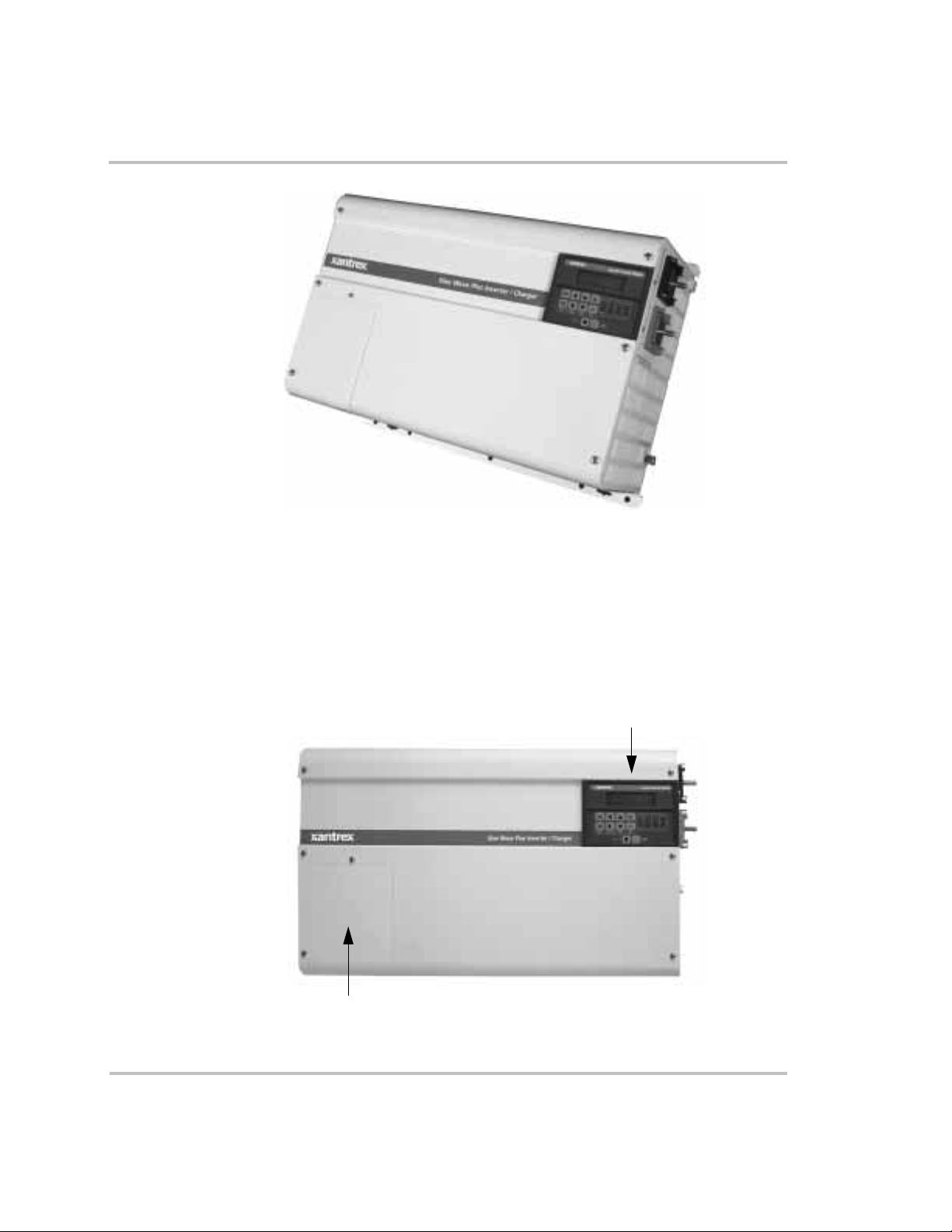
Front Panel
Figure 1-1
The Sine Wave Plus
The front of the Sine Wave Plus has the following features:
• the Inverter Control Module (ICM)
• the AC Access Cover
Inverter Control Module
AC Access Cover
Figure 1-2
976-0043-01-01 1–3
The Front Side of the Sine Wave Plus
Page 30
Introduction
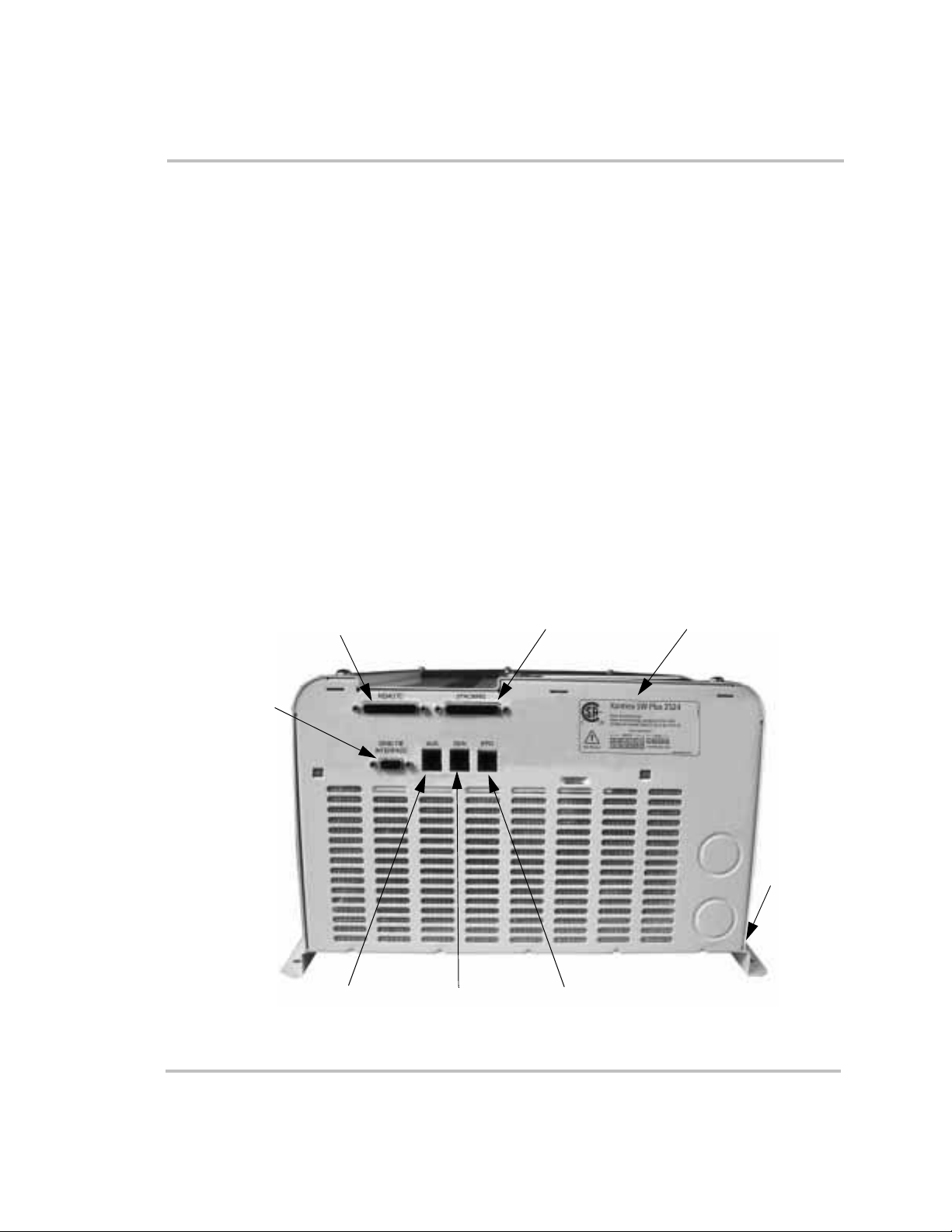
AC Side
The AC side of the Sine Wave Plus has the following features:
• The Remote Monitor Port for connecting the Inverter Control Module
(ICM) or the Inverter Communications Adapter (ICA)
• The Stacking Port for connecting two Sine Wave Plus inverters
• The AUX Port for connecting the Auxiliary Load Module (ALM)
• The GEN Port for connecting the Generator Start Module (GSM)
• The EPO Port for connecting an Emergency Power Off (EPO) switch
• Certification Label
• The Grid Tie Interface Port. The Grid Tie feature is currently not
available with the Sine Wave Plus models. However, the port has
been included in the event that the feature can be enabled with an
upgrade at a future date. Continue to check our website
www.xantrex.com for more information and future enhancements on
the Sine Wave Plus Inverter/Charger.
• The Serial Number Sticker is on the rail as shows in Figure 1-3.
Grid Tie
Interface
Port
(not used)
Figure 1-3
Remote Monitor Port
AUX Port
GEN Port
The AC side of the Sine Wave Plus
Stacking Port
EPO Port
Certification Label
Serial
Number
Sticker
1–4 976-0043-01-01
Page 31
Emergency Power Off (EPO) Option
The Sine Wave Plus offers an EPO option through the use of the EPO
Port. The EPO feature is designed to shut down the inverter from a remote
location (or switch).
Since the type of the switch will be dependent on the installation, EPO
switches are not provided with the Sine Wave Plus. However, many
commonly available emergency shut off switches will work with the Sine
Wave P lu s EPO. Consult your local system designer or qualified
technician for assistance.
The EPO is connected to the Sine Wave Plus with a telephone cord
(RJ11type connector) to the dedicated EPO port on the AC (left) side of
the inverter.
See Appendix G, “Emergency Power Off Switches” for additional
information about this feature and how to prepare a cable for it.
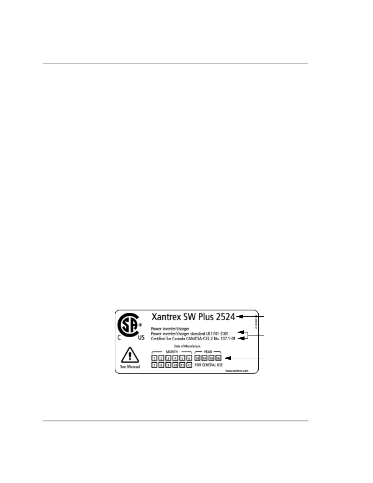
Certification Label
The Sine Wave Plus has been tested to nationally recognized safety
standards and has been found to be free from reasonably foreseeable risk
of fire, electric shock, and related hazards when installed and operated in
accordance with all the instructions provided in this manual and in
accordance with all applicable local and national codes.
Please refer to the Certification Label affixed to the AC side of the
inverter for specific agency information.
See Figure 1-3, “The AC side of the Sine Wave Plus” on page 1–4 for the
location of this information.
Basic Features
Model Number
Certification
Statement
Date of
Manufacture
Figure 1-4
976-0043-01-01 1–5
Certification Label
Page 32
Introduction
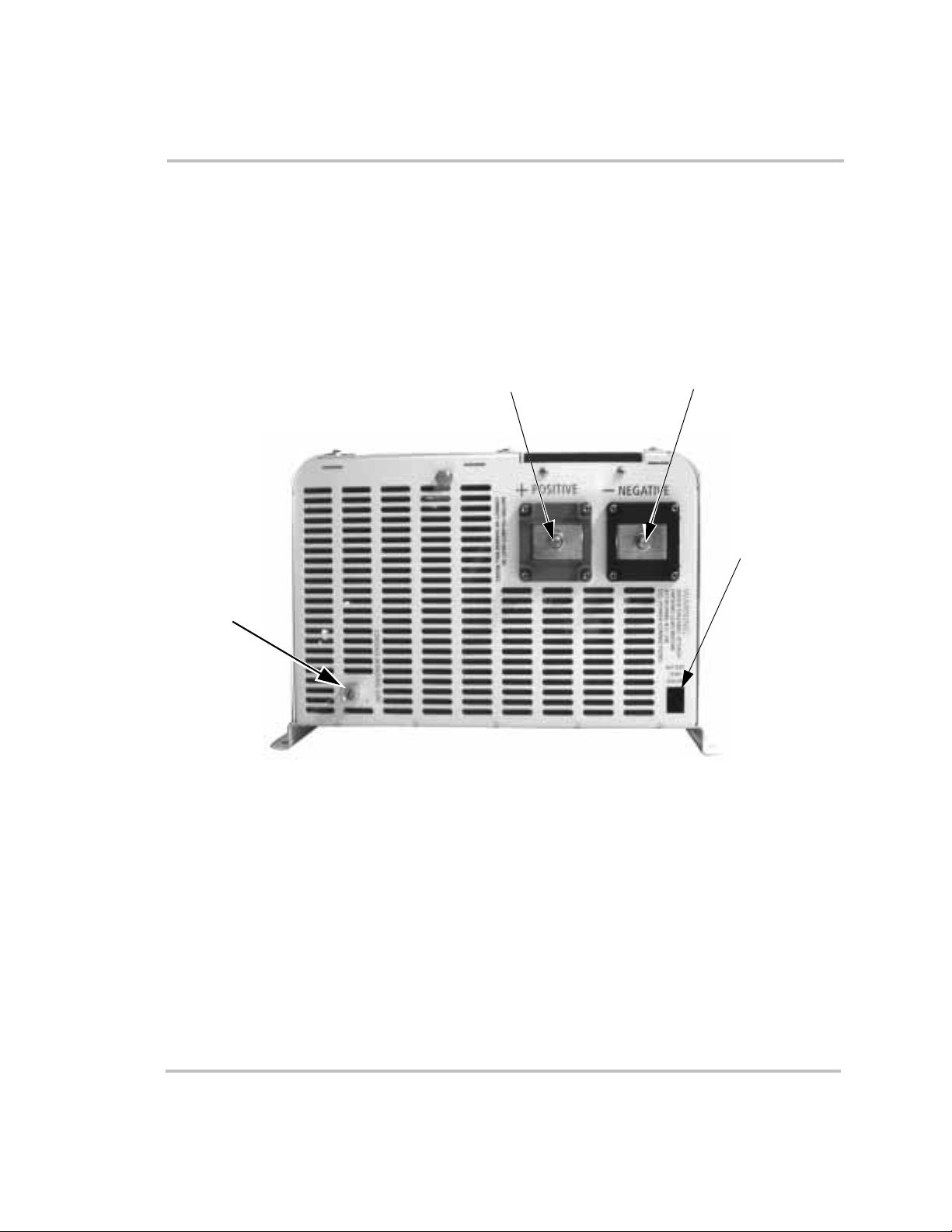
DC Side
The DC side of the Sine Wave Plus has the following features:
• the positive (+) battery terminal
• the negative (–) battery terminal
• the battery temperature sensor port
• the chassis ground lug
Chassis
Ground
Lug
Figure 1-5
Positive (+)
Battery Terminal
The DC side of the Sine Wave Plus
Negative (–)
Battery Terminal
Battery
Temperature
Sensor
1–6 976-0043-01-01
Page 33

Battery Temperature Sensor (BTS)
A BTS is provided with each Sine Wave Plus Inverter/Charger. This
sensor can easily be installed in the system to ensure proper charging of
the batteries based on temperature. Installing a BTS extends battery life
by preventing overcharging in warm temperatures and undercharging in
cold temperatures.
If more than one BTS is being used, install them adjacent to each other so
that they all detect a common temperature.
Basic Features
Figure 1-6
Battery Temperature Sensor (BTS)
See Table C-4, “Variances in Charging Voltage based on Battery
Temperature” on page C–14 and Table C-5, “Temperature Compensation
Calculation” on page C–14 for additional information.
976-0043-01-01 1–7
Page 34

Introduction
Top
The top of the unit has the following features:
• Circuit Breaker - This circuit breaker protects the unit’s internal
wiring while the unit is inverter or charging. It is not used for the
pass-through current. This is not a branch-circuit rated breaker.
Separate output breakers are still required. If the button is protruding
from the chassis as shown in Figure 1-7, it means the circuit breaker
has tripped open. Press the breaker back in to reset it.
• Warnings Label
• Ratings Label
Top View of Sine Wave Plus Inverter/charger
Circuit Breaker
AC End
Warnings Label
Circuit Breaker Open Circuit Breaker Reset
Ratings Label
DC End
Figure 1-7
1–8 976-0043-01-01
External Output Circuit Breaker
Page 35

2
System Configuration
Chapter 2, “System Configuration” contains information to
help you configure the Sine Wave Plus Inverter/Charger for
off-grid, on-grid, and backup power applications.
Page 36

System Configuration
Types of Applications
The Sine Wave Plus Inverter/Charger can be configured for the following
applications:
• OFF-GRID (stand-alone) applications where no utility power is
available. See Figure 2-17 through Figure 2-20 for illustrations of offgrid applications.
• ON-GRID applications where it can operate the AC loads when the
Utility System (grid) fails, keep the batteries charged, and/or function
as an energy management controller. See Figure 2-21 and Figure 2-22
for illustrations of on-grid applications.
Pre-Configuration Planning
System Output
Requirements
System Input
Requirements
Important:
permit office to ensure that the desired configuration will be codecompliant. Be sure to obtain the proper licenses and permits as required
by law.
Installations of this equipment should only be performed by skilled
personnel such as qualified electricians and Certified Renewable Energy
(RE) System Installers. For a list of Xantrex Certified RE dealers, please
visit our website at www.XantrexREdealers.com.
Pre-configuration planning is essential to ensure optimal performance for
your system. Pre-configuration planning includes, but is not limited to,
the following considerations.
❐ Single or dual inverters (based on output voltage and output watts
required)
❐ Output watts required (i.e., continuous capacity and surge capacity)
❐ Output voltage (120 Vac or 240 Vac)
❐ Utility power
❐ AC generator (See “Generator Considerations” on page 2–19)
Be sure to consult with your local utility company and/or
❐ Renewable energy systems (i.e., PV arrays, wind turbines etc.)
Code Compliance
and Permits
2–2 976-0043-01-01
❐ Local or national electrical codes
❐ Special permits or licenses (if required)
Page 37

Location
Considerations
Pre-Configuration Planning
❐ Mounting location for optimal performance and easy access of all
components
❐ Ventilation and clearance requirements for all components
❐ Mounting method (wall or shelf)
❐ Additional items/materials required for mounting
Grounding
Considerations
Battery
Considerations
Wiring
Considerations
❐ Grounding type (i.e., ground bar, ground bus, or ground rod)
❐ Neutral-to-ground bonding requirements
❐ Lightning and surge protection
❐ Battery type
❐ Battery cables and sizes
❐ Size of the battery bank and it’s configuration
❐ Location of battery bank to rest of system
❐ Types and sizes of wires needed
❐ Types and sizes of conduits needed
❐ Types and sizes of fuses and/or disconnects
❐ Additional equipment for code compliance (e.g., service panels,
conduit boxes, emergency shutoff switches etc.)
❐ Wire Routing
Additional
Equipment
❐ Additional components or accessories to complete the system design
(e.g., remote monitors, interface cables, stacking cables, DC charge
controllers, auxiliary load controllers, T240 autotransformers etc.)
Generator
Considerations
❐ Voltage Output Requirements
(120 Vac only, 120/240 Vac, or 240 Vac only)
❐ Auto-Start or Manual-Start
Important:
Auto-start generators require the addition of the GSM to
enable the inverter to control the operation of the generator. See
“Generator Considerations” on page 2–19 for additional information.
976-0043-01-01 2–3
Page 38

System Configuration
System Output Requirements
Determine the inverter output size requirements by calculating the
maximum, continuous capacity and surge (inrush current) capacity the
system will demand.
• Add all potential loads which would be on at once to determine
continuous power requirements.
• Add the surge current of all loads which might start at once to
determine surge requirements (e.g., washer spinner, waterpump and
refrigerator compressor could all start at once).
See Appendix C, “Understanding Amp-hour Requirements” for
assistance in determining the System Output Requirements.
System Input Requirements
Determine the input requirements based on the output requirements. In
other words, is grid power available or will renewable energy equipment
be used? Will a generator be used to supplement or backup the other input
sources?
See “Generator Considerations” on page 2–19 and Appendix D,
“Generators” for additional information regarding using generators for
system input.
Location Considerations
Dry Environment/
Stable Temperatures
Avoid Exposure to
Saltwater
Close to Battery
Bank
2–4 976-0043-01-01
Inverters contain sophisticated electronic components and should be
located in a well-protected, dry environment away from sources of
fluctuating or extreme temperatures and moisture.
The better the environment, the longer the inverter will last. Consider
installing your inverter in the same type of location in which you would
store high quality electronic equipment of equal value.
Exposure to saltwater is particularly destructive and potentially
hazardous. Internal corrosion caused by improper installation may cause
the inverter to prematurely fail and additionally will void the warranty.
Locate the inverter as close to the batteries as possible in order to keep the
battery cable length short. However, note the following warnings and
important notes about inverter location.
Page 39

Pre-Configuration Planning
WARNING: Explosion and Corrosion Hazards
Do not locate the inverter directly above the batteries or in the
same compartment as vented batteries.
Vented batteries generate hydrogen and oxygen, which if
accumulated, can be ignited by an arc caused by connecting the
battery cables or switching a relay.
Vented batteries also generate hydrogen-sulfide gas, which is
corrosive to electronic equipment.
Important:
Batteries can sometimes release explosive gas, please see the battery
manufacturer’s recommendations for ventilation requirements.
Do not mount the inverter in the same space with the generator. The heat
and dust and from the generator can do damage to the inverter.
RFI Interference Inverters can generate radio frequency interference (RFI). Locate any
sensitive electronic equipment susceptible to RFI as far away from the
inverter as possible. This includes radios and televisions.
Electromagnetic
Interference
Fire Safety All Sine Wave Plus inverter/chargers meet UL fire safety standards as
Inverters can also emit strong electromagnetic fields. This should be
considered when choosing an installation location.
See “FCC Information to the User” on page viii for additional
information regarding RFI requirements.
outlined in UL 1741. As such, in the event of a failure, the Sine Wave Plus
is designed to fail safe. Be sure the specific mounting and ventilation
requirements outlined in this Owner’s Manual are followed carefully.
Mounting Considerations
Method The inverter can be mounted on a vertical surface (or wall) or on a shelf.
The advantage of the wall mounting is to provide easier access to the
controls and displays.
Requirements The mounting surface (wall or shelf) must be capable of supporting twice
the weight of the inverter. The keyhole slots should not be used as the
only method of securing the unit to the mounting surface. Use all ten
mounting holes and all four keyhole slots for securing the unit and use
0.25-inch diameter bolts for mounting.
976-0043-01-01 2–5
Page 40

System Configuration
Clearance for fire
safety
Please keep all readily flammable materials (cloth, paper, straw, plastic
etc.) at a minimum clearance of 24" (60 cm.) from the top surface (when
wall mounted) and 12" (27 cm.) from either side surface and the front of
the Sine Wave Plus. Readily flammable materials refers to instantly
combustible substances such as cloth, paper, straw, and plastic sheeting.
Ventilation Requirements
Location Install the inverter in a well-ventilated area/enclosure for proper
operation. The inverter’s thermal shutdown point will be reached sooner
than normal in a poorly ventilated environment resulting in reduced peakpower output and surge capability as well as shorter inverter life.
Requirements Provide a minimum clearance of 3 inches (12 inches is preferred) around
the top and 6 inches at the AC- and DC-side of the inverter for ventilation.
A fan-forced, fresh-air vent (on the inverter’s AC side) allows cool air to
enter the unit and exit from the DC-end of the inverter. Ensure that this
vent is not obstructed with foreign objects, such as dirt and dust and that
the minimum clearances are met.
Airflow clearance All air ventilation openings should have 6 inches of clearance and there
should be no nearby cover over the top of the unit. This is to prevent
warm, exhausted air from the unit being drawn back into the unit, which
could cause premature shutdown due to overheating.
Screening The unit is equipped with screening to prevent insects and rodents from
entering. This screening needs to be checked and cleaned regularly from
the outside to prevent dust buildup.
Grounding Considerations
The following points should be taken into consideration when planning
how to properly ground the system, whether or not you’re installing a new
system or integrating new parts into an older system.
Important:
application. All installations must comply with national and local codes
and ordinances. Consult local and/or national codes and the NEC for
specific grounding and bonding requirements for the desired installation.
DC System Grounding
The Sine Wave Plus can be used in either a positive or negative grounded
system. However, unless you are installing the inverter into an existing
positive grounded system (i.e., a telecommunications system), it is highly
recommended to use negative grounding.
2–6 976-0043-01-01
The grounding requirements vary by country and by
Page 41

Pre-Configuration Planning
Positive Ground A positive ground is where the positive conductor from the battery bank is
bonded to earth ground. This arrangement is most often used in
telecommunications systems where an isolated ground is a requirement.
Negative Ground A negative ground is where the negative conductor from the battery bank
is bonded to earth ground. This is the most common form of grounding
methods used for residential and commercial applications. The Sine Wave
Plus meets FCC part 15 Class B regulations in a negative grounded
system. See “FCC Information to the User” on page viii for additional
information.
The remainder of this manual will assume the negative ground
convention.
Inverter Grounding
Important:
ground applications) to ground can only be in one location in the DC
system. This DC ground bond must be made in a non-serviceable item in
the DC system. The Xantrex DC175 and DC250 can have the optional
DCBB installed to provide the DC system bond. Additionally, the
Xantrex PVGFP can also provide this bond and comply with NEC
requirements for roof mounted PV arrays installed on dwelling units
(homes).
The bonding of the DC negative (or positive in positive
WARNING: Shock Hazard
Attach the ground lead BEFORE attaching any AC or DC
power connections.
The inverter/charger should be connected to a grounded, permanent
wiring system with the AC and DC grounds common bonded to each
other and should be bonded to the grounding system at only one point in
the system. See “Bonding the Grounding System” on page 2–9 for
additional information.
The size for the grounding conductor is usually based on the size of the
circuit breaker in the DC system. The table below provides battery DC
disconnect sizes and minimum wire sizes of copper ground wires for
grounding systems.
It is recommended that the size and gauge of grounding wire should be
more than the NEC minimum requirements when installing power
sources such as inverter/chargers or generators.
976-0043-01-01 2–7
Page 42

System Configuration
Table 2-1
Disconnect Sizes per NEC
Battery DC
Disconnect Size
30 amp or 60 amp #10 AWG
100 amp #8 AWG
200 amp #6 AWG
300+ amp #2 AWG or greater
Note:
Field experience has demonstrated that long distances or high
impedance grounds can cause equipment malfunction or damage.
WARNING: Explosive Hazard
Never use a gas pipe or gas line for grounding purposes. The
inverter is a power source and it is intended to be grounded at
the service/main ground rod.
Equipment or Chassis Grounding
Recommended Minimum Safety Ground Wire and DC
Minimum Size of
Copper Ground Wire
WARNING: Shock Hazard
Attach the ground lead BEFORE attaching AC or DC
power connections.
This grounding connects the metallic chassis of the various enclosures
together to have them at the same voltage potential. This reduces the
possibility for electric shock. It also provides a path for fault currents to
flow through to blow fuses or trip circuit breakers. The size of the
connecting conductors should be coordinated with the size of the overcurrent devices involved. Under some circumstances, the conduit and
enclosures themselves will provide the current paths.
Grounding Electrodes/Ground Rods
The purpose of the grounding electrode (often called a ground rod) is to
“bleed” off any electrical charge that may accumulate in the electrical
system and to provide a path for “induced electromagnetic energy” or
lightning to be dissipated. The size for the conductor to the grounding
electrode or grounding system is usually based on the size of the largest
conductor in the system. Most systems use a copper-plated rod as the
2–8 976-0043-01-01
Page 43

Pre-Configuration Planning
grounding electrode. The rod should be 5/8 inch (16 mm) round by 8 feet
(2 meters) long and driven into the earth. It is also common to use copper
wire placed in the concrete foundation of the building as a grounding
system. Either method may be acceptable, but the local code will prevail.
Connection to the ground electrode should be done with special clamps
located above ground where they can be periodically inspected.
Note:
your system, are subject to severe damage from the effects of lightning.
Lightning damage is NOT covered by your warranty. If your installation
is in an area of high probability for lightning, you should consult with a
local lightning expert or your authorized Xantrex installer to determine
what extra precautions should be taken to protect your equipment.
Many large systems use multiple ground rods. The most common
example is providing a direct path from the solar array to earth near the
location of the solar array. Most electrical codes want to see the multiple
ground rods connected by a separate wire with its own set of clamps. If
this is done, it is a good idea to make the connection with a bare wire
located outside of the conduit (if used) in a trench. The run of buried wire
may be a better grounding electrode than the ground rods. Well casings
and water pipes can also be used as grounding electrodes. Under no
circumstance should a gas pipe or line be used.
Important:
This inverter, along with all other power electronic devices in
Consult local codes and the NEC for more information.
Bonding the Grounding System
Bonding means connecting one of the current-carrying conductors
(usually the AC neutral and DC negative) to the grounding system. When
the other ungrounded conductor (the hot or positive) touches the
grounding system, current will flow through it to the point of connection
to the grounded conductor and back to the source. This will cause the
over-current protection to stop the flow of current, protecting the system.
This point of connection between the grounding system (ground rod), the
current carrying grounded conductor (AC neutral and DC negative), and
the equipment grounding conductor (green ground wire, equipment
ground) is called a “bond”.
Bonding location Bonding is usually located in the over-current protection device
enclosures (both AC and DC). Although it can be done at the inverter,
codes do not generally allow it since the inverter is considered a
976-0043-01-01 2–9
Page 44

System Configuration
“serviceable” item that may be removed from the system. In residential
systems, it is located at the utility panel, after the power has gone through
the kilowatt-hour meter of the utility (if present).
Bonding at the AC
Panel
Bond at one point
only
Renewable energy systems, with no grid connection, can be grounded at
the main AC distribution panel. Renewable energy systems should be
grounded to the same grounding electrode as the AC distribution panel.
Bonding must be done at only one point in an electrical system.
Inherently, Xantrex systems have two separate electric systems; a DC
system and an AC system. This means that two bonding points will occur
in all inverter applications. The bonding point will also be connected to
the equipment (chassis) grounding conductors. It is common to have two
separate conductors connect the ground electrode and the two bonding
points. Each conductor should use a separate clamp.
Important:
only one place, in the system.
If the generator is the main source of power, (i.e., no utility grid power)
then the neutral and ground connections are bonded at the main AC
distribution panel.
If the utility grid is the main source of power, then the bond should be at
the utility AC distribution panel.
If there is no utility or generator in the system, then the ground/neutral
bond should be in the inverter AC distribution panel.
The ground and neutral must be bonded at one place, and
Battery Considerations
WARNING: Shock Hazard
The Sine Wave Plus is intended to operate with batteries as its
source of DC power. DO NOT connect DC charging sources
such as PV, wind turbines, or micro-hydro turbines directly to
the Sine Wave Plus.
Dangerous conditions which can be harmful to personnel and
equipment can exist when DC charging sources are connected
directly to the inverter, these conditions include: unexpected
AC power output from inverter/charger and damage to inverter/
charger from unregulated high DC voltage input.
2–10 976-0043-01-01
Page 45

Pre-Configuration Planning
Accessibility Locate the batteries in an accessible location if maintenance is required.
Two feet clearance above the batteries is recommended for access to the
battery caps. They should be located as close to the inverter as possible
without limiting access to the inverter’s disconnects. Install the batteries
to the right of a wall-mounted inverter for easy access to the DC side of
the inverter and shorter cable runs. The battery bank may also be placed
on the opposite side of the wall on which the inverter is mounted.
Vented Enclosures For safety and to limit access to the batteries, the batteries should be
housed in an enclosure or dedicated room that is lockable or screened, and
ventilated. It should be vented to the outside by a one inch minimum vent
pipe located at the top of the enclosure. Install an intake vent at the
bottom of the inclosure to promote air circulation.
Important:
sulfide gases and must not be overlooked when designing an enclosure.
Enclosure
Requirements
The enclosure should be made of an acid resistant material or have a
finish that resists acid to prevent corrosion and be capable of containing
the electrolyte from at least one battery should a leak occur.
Enclosures located outside must be rainproof and screened to prevent
access by rodents or insects and insulated from extreme temperatures.
Batteries will give their best performance and service life when operating
in a 20 to 25 °C environment.
Note:
enclosure requirements.
Battery Bank Requirements
Note:
battery bank is 100 Ah. The recommended battery bank size is
determined by the battery bank worksheet in Appendix C (Tab le C-1 ,
“Determining Average Daily Load in Amp-hours” on page C–7). It is
not recommended or designed to operate this inverter without batteries.
These vents exhaust corrosive and explosive hydrogen
Consult battery vendor for additional information on battery
Based on the peak current of the inverter, the minimum allowed
976-0043-01-01 2–11
Page 46

System Configuration
Preparing a battery bank includes the following considerations:
1. Determine types of batteries to be used.
2. Determine the number of batteries required for the battery bank.
3. Prepare the battery bank according to type of battery selected and
configure the battery bank to optimize voltage output according to
system requirements.
See Appendix C, “Battery Information” for additional information on
determining battery bank type and configuration.
The DC voltage of your inverter must match the DC voltage of your
system and all of its accessories. In other words, if you have a 24 volt
inverter, then the battery bank and all other DC devices in the system
must be configured for 24 volts.
WARNING: Fire Hazard
Undersized cables can overheat and melt, creating a fire hazard
when subjected to heavy (peak) loads. Always use a properly
sized cable and length rated for the amperage of the inverter
and batteries.
Battery Cable Requirements
Important:
inverter DC connections. Do not use coarse stranded wire, as the lack of
flexibility may damage battery and inverter terminals.
Battery cables must be the correct size and length to optimize
performance and ensure the safety of the system. Larger diameter cables
(smaller AWG number) have less voltage drop and are, therefore, more
efficient when transferring power to and from the batteries. The use of
oversized cables (e.g., 4/0 cables) will allow you to take advantage of the
improved surge performance of the Sine Wave Plus inverters.
DO NOT cut corners on the battery cable recommendations in this
manual. It is absolutely imperative that you adhere to the battery cable
size (wire gauge) and length recommendations provided in this section. If
cables that are too long or of insufficient gauge (i.e., undersized, diameter
too small) are used, then inverter performance will be adversely affected.
In addition to poor inverter performance, undersized cables can result in
Use only fine stranded copper cables for battery and
2–12 976-0043-01-01
Page 47

Pre-Configuration Planning
fire caused by overheating wires. Any damage to the inverter caused by
overheating from undersized wire is NOT covered by the Xantrex
warranty.
Important:
Figure 2-1 is for reference only. Sizes shown are for the
conductor. Do not include any insulation when determining your wire
size. Due to printing anomalies, these dimensions may not be to scale.
Size
Diameter
Size
Diameter
Size
Diameter
12
14
.07210.1158.1466.184
.073
1
.335
250 MCM
.580
1/0
.380
300 MCM
.635
2/0
.420
350 MCM
.690
4
.235
3/0
.475
400 MCM
.730
3
.281
2
.295
4/0
.530
500 MCM
.820
AWG Wire Size Reference Chart
Battery Cable
Length
Figure 2-1
Cable length is another important factor. Runs should be kept as short as
practical. Longer cable runs increase resistance, thus lowering the overall
efficiency of the system. This is especially true in lower voltage systems
where, depending upon the length of the cable run, it may be necessary to
oversize the diameter of the wire, or parallel (double) the cables. Table 2-
2 provides recommended minimum cable sizes for various cable lengths
and inverter amperage per NEC guidelines. It is recommended that cable
has battery acid resistant insulation and is rated for 90 °C (32 °F) or
better.
Be sure to check with any local regulatory agencies for additional
requirements.
Battery Cable Lugs Battery cables must have crimped or soldered and crimped copper
compression lugs. Soldered connections alone are not acceptable.
976-0043-01-01 2–13
Page 48

System Configuration
DC Disconnects and
Overcurrent
Protection
High quality battery cables are available from Xantrex in an assortment of
lengths from 1½ to 10 feet in #2/0 AWG and from 1½ to 15 feet in #4/0
AWG sizes. These cables are color-coded with pressure crimped, sealed
ring terminals.
For safety and compliance with regulations, battery overcurrent
protection is required. Fuses and disconnects must be sized to protect the
wiring in the system and are required to open before the wire reaches its
maximum current carrying capability.
Xantrex DC 175
and DC 250
Table 2-2
Inverter
Model
2524 134 167 #2/0 AWG
2548 67 84 #2/0 AWG
Minimum Required Battery Cable Size Versus Length
Maximum
Continuous
DC amps
a. “Maximum Continuous DC amps”, as shown in this table, is based on low
battery voltage with an efficiency of 85%.
b. “NEC amps”, as shown in this table, is based on low battery voltage, and
efficiency of 85%, and a 125% NEC derating.
NEC
a
amps
Up to 5 Feet
b
One-way
(67.4 mm2)
(67.4 mm2)
Up to 10
Feet
One-way
#4/0 AWG
(107 mm2)
#4/0 AWG
(107 mm2)
Up to 15
Feet
One-way
Not
Recommended
#4/0 AWG
x 2
The NEC requires both overcurrent protection and a disconnect switch for
residential and commercial electrical systems. These items are not
supplied as part of the inverter. However, Xantrex offers a DC circuit
breaker disconnect module specifically designed for use with Xantrex
inverters to meet NEC compliance. Two amperage ratings are available: a
DC250 (250 amps) and a DC175 (175 amps) in either single- or doublepole configurations for single- or dual-inverter installations.
See “DC Disconnect Boxes (DC 175/DC250)” on page 2–24 for
additional information on the Xantrex DC 175 and DC 250.
After selecting battery cables based on the distance from the battery bank
to the inverter, add battery overcurrent protection in the battery cable line,
based on Table 2 -3. This table will help you to determine your maximum
breaker/fuse size based on the cable size you selected previously.
2–14 976-0043-01-01
Page 49

Pre-Configuration Planning
Trace™ Fuse Block
(TFB)
Table 2-3
Cable Size
Required
#2/0 (00) AWG 175 Amps 175 Amps 265 Amps
#4/0 (0000) AWG 250 Amps 250 Amps 360 Amps
Battery Cable to Maximum Breaker/Fuse Size
Maximum
Rating in
Conduit
a. The term “free air” is defined by the NEC as cabling that is not enclosed
in a conduit or a raceway. Cables enclosed in conduit or raceways have
substantially lower continuous current carrying ability due to heating
factors.
b. The NEC allows rounding to the next highest standard fuse size from the
cable rating (i.e., 150 amp cable size rounds up to a standard 175 amp
size).
Breaker/
Fuse Size
Rating in
“Free
a
Air”
Maximum
Breaker/
Fuse Size
300 Amps
400 Amps
b
b
Some installations may not require conduit or a disconnect device,
although overcurrent protection is still required. Xantrex offers a fuse
block (TFB) providing the code required inverter overcurrent protection
for these applications. These fuses are available in 110, 200, 300 and 400
amp sizes.
Important:
From this point on in this manual, any reference made to a
“DC disconnect” means either a DC breaker or a fuse with a disconnect
switch, which will depend on your specific type of installation.
Battery Requirements for Dual Inverter Systems
The success of “stacked” or “dual” inverter systems is very dependent on
the quality and maintenance of the DC connections. Stacked inverter sets
are far less forgiving to long, undersized, uneven, and/or poor connections
than are single inverters. You cannot run two stacked inverters each from
separate battery banks.
Dual Inverters
(not stacked)
Series Stacked When inverters are “stacked” they must have a common battery bank to
976-0043-01-01 2–15
Dual inverter configurations can be used without using the stacking
interface cable. In this configuration, two inverters separately run isolated
loads from the same battery bank or individual battery banks.
operate from. In other words, the DC negative of one inverter must be
common with the second inverter and likewise for the DC positive.
For example:
If you have eight 6-volt batteries in a 24-volt configuration, they
would be arranged in two rows of four batteries (see Appendix C for
diagrams of various arrangements).
Page 50

System Configuration
The negative ends of the two “strings” of batteries must be jumpered
together to become common with each other.
Likewise, the positive ends of the two “strings” must also be
jumpered together so that they are also common with each other.
Shunts near the
inverter
Losses from the cables will cause each inverter to measure slight
differences in actual voltages, in spite of having the battery bank common
to both inverters. It is easy to have the DC negatives common closer to the
inverters if an in-line metering shunt is installed near the inverters before
the negative cables attach to the negative battery terminal.
Jumpers The use of optional bonding jumpers can improve how each inverter
measures the DC voltage for decisions when charging amperages should
be reduced as the batteries become charged. The bonding jumpers allow
the inverters to agree better on what the voltage actually is. The longer the
DC cables are, the more likely you will need bonding jumpers.
Shunts near the
batteries
If a shunt is installed closer to the battery bank than the inverters, a
bonding jumper should be installed from one inverter’s negative terminal
to the other inverter’s negative terminal. By using a negative bonding
jumper and/or a metering shunt near the inverters, the inverters will have
a better zero volt (DC negative) reference to measure the DC voltage.
DC disconnects The DC positive is more difficult due to the need to have DC disconnects
in each cable for the inverters. The primary reason for the DC disconnects
is for overcurrent protection for the cable it is installed in. By using a
positive bonding jumper the inverters will have a more accurate DC
positive reference to measure the DC voltage.
Bonding jumpers in
positive line
A bonding jumper may be installed from one inverter’s positive terminal
to the other inverter’s positive if a warning is placed near the DC
disconnects. This means that either DC disconnect can energize both
inverters while the other DC disconnect is not yet turned on. This is called
"backfeeding" a disconnect or circuit breaker. The 2002 NEC,
Section 404.6, C, Exception, allows switches to be backfed if a warning
such as the following is permanently marked on or adjacent to the
disconnect switches. A sample of this warning label is provided in Figure
2-2. These labels are not available or provided by Xantrex, but may be
available from your local electrical warehouse.
WARNING: Shock Hazard
Load side terminals may
be energized by
backfeed.
Figure 2-2
2–16 976-0043-01-01
Sample Warning Sticker for Backfeed Conditions
Not provided by Xantrex.
May be available at your local
electrical warehouse.
Page 51

Pre-Configuration Planning
DC disconnects and
over-current devices
The size of the bonding jumper must be the same gauge as that of the
primary battery cable in which the overcurrent device (DC disconnect) is
installed, and as always, the overcurrent device must be sized
appropriately for all cables attached to it. If one overcurrent device trips
then there will be only half the amount of current available for both
inverters to run from. If you want to run only one inverter while the other
is shut down (for example, for maintenance procedures), the positive
bonding jumper must be removed or there must be an appropriately sized
switch installed in the bonding jumper.
Battery Temperature
Cold temperatures Cold temperatures drastically reduce battery capacity and performance.
The battery enclosure, therefore, should provide a fairly stable
temperature for the batteries. If batteries are installed in a cold
environment, insulation should be installed to protect the batteries from
the cold. The insulation will act as a barrier to the cold and also keeps the
heat generated by the batteries inside the enclosure providing a more
stable temperature and better system performance.
Hot temperatures High battery temperatures greatly shortens the life of the batteries also.
The battery enclosure should not be installed in direct sunlight where the
sun can overheat the batteries. Locate the enclosure where it will be
protected from the sun and provide vents in the top and bottom of the
enclosure to provide air flow throughout the enclosure.
For best performance, locate the batteries where they are in a room
temperature of 20 to 25 °C (68 to 77 °F)
Battery
Temperature Sensor
A BTS is provided with each Sine Wave Plus. This sensor can easily be
installed in the system to ensure proper charging of the batteries based on
temperature. Installing a BTS extends battery life by preventing
overcharging in warm temperatures and undercharging in cold
temperatures.
See “Installing the Battery Temperature Sensor (BTS)” on page 3–18 for
instructions on installing the Battery Temperature Sensor.
976-0043-01-01 2–17
Page 52

System Configuration
Wiring Considerations
Code Compliance
Important:
to confirm grounding and bonding requirements specific to the intended
system. All wiring and installation methods should conform to applicable
electrical codes and building codes.
Conduit Boxes For maximum safety and, in some cases, for code-compliance, run the AC
and DC cables in conduit(s). Pre-plan the wire and conduit runs carefully
before installing any components.
Main AC
Distribution Panel
(Utility fed)
Generator
Disconnect Switch
Subpanel/Inverter
Panel
The AC1 input to the inverter requires a 60-amp breaker maximum be
installed into the main AC distribution panel (double-poled if stacked) to
protect the wiring in accordance with NEC. This breaker supplies utility
grid power to the inverter. AC1 is not used in off-grid applications.
Installing a disconnect switch with an appropriately sized circuit breaker
(60 amp maximum) between the generator and inverter provides overcurrent protection for the wiring between the generator and the inverter’s
AC2 terminal. This is also a good safety practice as it also provides a
means to prevent the inverter wiring from becoming energized in the
event that an electric-start generator starts unexpectedly while the inverter
is being serviced.
In on-grid applications, loads backed up by the inverter will need to be
rerouted from the main AC distribution panel to a subpanel. In off-grid
application, the inverter panel functions as the main electrical panel.
Always use properly rated circuit breakers.
Be sure to consult the local and national electrical codes
WARNING: Fire Hazard
Check existing structure wiring for “multi-branch wiring”. For
new construction, do not use “multi-branch wiring”.
For both cases refer to Appendix F, “Multiwire Branch Circuit
Wiring” for additional information.
Fuses and/or DC
Disconnects
2–18 976-0043-01-01
Install a DC disconnect breaker or fuse in the positive, ungrounded,
battery line. This breaker protects the DC wiring in the event of an
accidental short. Size the breaker in accordance with the battery cables.
Switch this breaker OFF (or remove the fuse) whenever servicing the
batteries or inverter(s).
Page 53

Pre-Configuration Planning
Wire size for AC
Connections
Wire Routing
Note:
NEC code.
#6 AWG THHN wire for all AC wiring (input and output) is
recommended.
Determine all wire routes both to and from the inverter, and which
knockouts are best suited for connecting the AC conduits. Possible
routing scenarios include the following.
• AC and DC grounds to an external ground rod
• AC input wiring from the main service panel to the inverter/charger
• AC input wiring from the generator to the inverter/charger (if used)
• AC output wiring from the inverter/charger to the sub-panel
• DC input wiring from the PV array to the controller/batteries
• DC input wiring from the batteries to the inverter/charger
• BTS cable from the batteries to the inverter/charger (keep separate
• Remote control cable to the inverter/charger (if used)
• Load circuit wiring rerouted from the main service panel to the sub-
A fuse without a switchable disconnect alone does not meet
(on-grid applications only)
from battery cables)
panel (on-grid applications only)
Important:
making cuts in the walls. Cut holes in the walls at appropriate locations
for routing wiring/cables.
Check for existing electrical wiring or plumbing prior to
Generator Considerations
Important:
information which can be used to aid the generator manufacturer or
electrician in assisting with your installation. Xantrex is not responsible
for providing detailed technical support or wiring instructions for
generator operation.
976-0043-01-01 2–19
The information contained in this manual is basic wiring
Page 54

System Configuration
Purpose An engine generator can be used as follows:
• as an input power source instead of (or in conjunction with) the utility
power, or
• as a backup power source (connected via additional hardware) to
automatically power the loads when utility is not present (utility
outage), and/or
• to charge the batteries.
Stable Voltage The generator should provide a stable voltage and frequency output for
the inverter to synchronize with.
AC wind turbines and small scale AC water turbines are not
recommended for use as AC power sources as they may not be able to
provide a stable voltage and frequency as loads and charger requirements
change. The only way to practically use sources such as these is to take
the AC power and rectify it into DC. Be sure to include a diversion type
controller (e.g., Xantrex C-Series) to protect the batteries from
overcharging.
Types of Generators There are AC generators and DC generators.
AC Generators AC generators can power AC loads and charge batteries. An AC
generator is better suited for residential applications, since the majority of
loads require AC power.
DC Generators DC generators can power DC loads and charge batteries. In a residential
application, DC generators are primarily used to charge the batteries.
Output
Requirements
An AC generator can output 120 Vac only, 120 Vac and 240 Vac together,
or 240 Vac only depending on the overall needs of the system. The
generator must be large enough to provide adequate power to charge the
batteries and support a certain amount of AC loads. If the generator is not
large enough, the amount of time it takes the inverter to charge the
batteries will increase.
A DC generator would be primarily used to charge the batteries. AC loads
are only powered by the energy stored in the batteries. The generator must
be large enough to provide adequate power to charge the batteries.
Starting
requirements
Generators can either be manually started, or when properly equipped,
automatically started. The Sine Wave Plus can operate well with either
kind of generator. It is recommended, however, to consult the desired
generator’s manufacturer to ensure the generator of choice is best suited
for the desired application.
Manual-start and
Electric-start
generators
2–20 976-0043-01-01
When using a manual-start or electric-start generator, the generator is
connected to the inverter AC2 input but is not controlled by the inverter.
The starting and stopping of the generator occurs at the generator.
Page 55

Auto-start
generators
Pre-Configuration Planning
Manual-start generators are started with a recoil-start pull cord. Electricstart generators are started by turning an ignition/starter key, switch, or
similar means.
These generators typically do not have self-protection features to shut
down the generator in the event of low oil pressure, over-heating,
overcranking, etc. and therefore are not designed for unattended starting
and operation.
Be sure if using a manual-start or electric start generator that the generator
is place in where it can be accessed easily to be started. After the
amperage limits for AC2 are programmed, these generators may be
started and stopped with no action necessary on the inverter control
panel."
When using an auto-start generator, the generator is connected to the
inverter AC2 input. The inverter controls the operation of the generator
with the assistance of the optional GSM. Auto-start generators are
equipped with terminals for signal wires to be routed and connected to a
remote switch/relay (a "dry contact") to signal the generator to run and/or
stop.
Auto-start generators are equipped with self-protection features to disable
starting and/or to shut down a generator in the event of low oil pressure,
over-heating, overcranking, etc. When generators are equipped with these
protection features, they are designed for unattended starting and
operation and may be compatible with the Sine Wave Plus with the
optional GSM.
Be sure to locate an auto-start generator in a place protected from
extremes of temperature so it can successfully start and operate without
assistance.
Important:
Plus can only function on generators equipped with two- or three-wire
auto-start operation. Not all electric-start generators have this feature;
most auto-start generators do. Check with your generator supplier and
make sure this feature is available. Additional hardware may be required.
Starting parameters The generator can be set to start based on four different, user-specified,
requirements with different requirements for each:
• battery voltage
• inverter load current
• time of day
•exercise time
976-0043-01-01 2–21
The automatic generator start feature of the Sine Wave
Page 56

System Configuration
If used with an application that includes utility power, the generator will
be started only if utility power is not available, as it is not possible to use
both generator and utility power at the same time (except for scheduled
exercise periods).
It is safe for both the utility and generator inputs to be energized at the
same time, although the inverter can only take power from one source at
any given time.
See “Generator Starting Scenarios” on page 7–18 of this manual for
specific instructions on setting the generator-start/stop conditions.
Additional/Optional Equipment Considerations
The following components are available for use with the Sine Wave Plus.
Some of these items may be required depending upon the intended use of
the inverter to make the installation code-compliant. These components
are not provided with the inverter and must be purchased separately.
Important:
company to ensure complete compliance with local regulations.
AC Conduit Box (ACCB)
The AC Conduit Box (ACCB) connects to the AC side of the inverter and
accepts AC conduit runs. The AC conduit box includes bypass/disconnect
breakers.
Be sure to consult with your local inspector and/or utility
Figure 2-3
2–22 976-0043-01-01
AC Conduit Box
Page 57

DC Conduit Box (DCCB)
The DC Conduit Box (DCCB) connects to the DC side of the inverter and
accepts DC conduit runs. It can also accommodate a fuse to comply with
CSA requirements for Canadian installations. See the Fuse Block section
below for additional information. Also consult with your system designer
and/or local regulatory agency for fuse size requirements. The DC
conduit box is not provided with the inverter and must be purchased
separately.
Additional/Optional Equipment Considerations
Figure 2-4
Figure 2-5
976-0043-01-01 2–23
DC Conduit Box
Sine Wave Plus with AC and DC Conduit Boxes Installed
Page 58
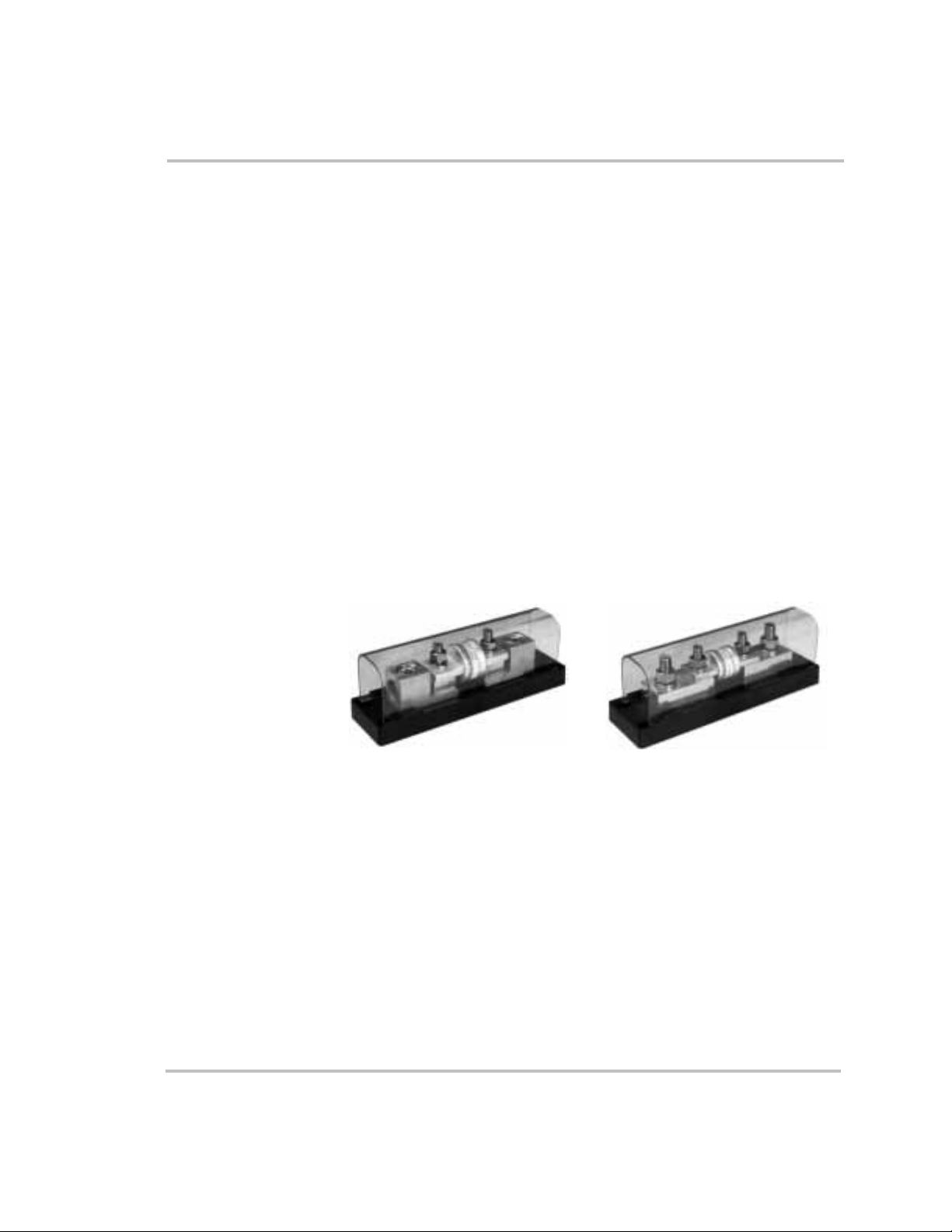
System Configuration
Fuse Block
The Trace™ brand fuse block (TFB) protects the power system’s DC
wiring should an overcurrent condition occur. The fuse block is placed
between the battery’s ungrounded conductor (usually the positive cable)
and the DC input terminal of the inverter.
The TFBs include a fast acting, current limiting class-T fuse providing
extremely fast protection when a short circuit occurs. When the fuse is
properly matched to the system current, its time delay allows the inverter
to surge to full power without blowing the fuse. A plastic cover prevents
accidental short circuits to the fuse terminals. Fuse sizes include 110, 200,
300, and 400 amps.
There are two types of fuse blocks available. The TFBxxxC fuse block
has “set” screw lugs for cables with no terminal connector’s on the ends
(known as C-type or stripped-end battery cables). The TFBxxx fuse block
has stainless steel bolt connections for cables with ring terminals (known
as ring-lugged battery cables). Both fuse blocks include a black poly
carbonate, fiberglass reinforced base and a clear poly carbonate snap-on
cover.
Fuse Block for C-type
(stripped end) Battery Cables
(TFBxxxC)
Figure 2-6
Fuse Blocks
Fuse Block for Ring-lugged
Battery Cables (TFBxxx)
DC Disconnect Boxes (DC 175/DC250)
Xantrex provides two options for disconnect boxes. The DC175 and
DC250 protects your batteries, inverter, and DC cables from damage
caused by short circuits and overloads through use of a UL listed, high
interruption capacity circuit breaker. This breaker is designed to interrupt
the tremendous amount of power a battery can deliver when short
circuited. It is also designed to have a long enough time delay to allow the
inverter to surge to full power without nuisance tripping of the breaker. If
the breaker does trip, it’s easily reset.
2–24 976-0043-01-01
Page 59
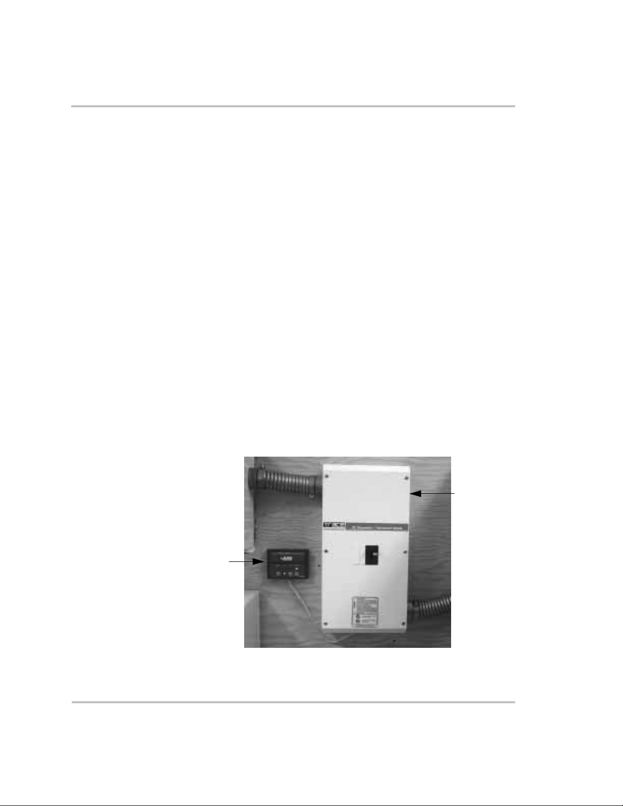
Battery Status Meter (TM500A)
The TM500A features six data monitoring functions and three indicators
including:
• State of charge/amp-hour content (full or percent of capacity)
• State of charge/voltage (real-time voltage level, historical high and
low system voltage)
• Amps (real-time amps, total charging amps, total load amps)
• Amp hours removed
• Days since fully charged
• Cumulative amp hours
• Recharge indicator
• Low-voltage indicator
• Full-charge indicator
The unit is configurable for specific system or application functions such
as setting the CHARGED indication parameters, battery capacity,
charging efficiency, low-battery warning conditions and a recharge
reminder. The TM500A can monitor any battery supply from
approximately 8 to 65 volts, track energy consumption and estimate
remaining battery life.
The TM500A operates on 12-, 24-, or 48-volt battery systems (48-volt
systems require an optional shunt board).
Additional/Optional Equipment Considerations
DC 250
TM500A
Figure 2-7
976-0043-01-01 2–25
DC250 Disconnect Box and TM500A Battery Status Meter
Page 60

System Configuration
Remote Monitors
Three options are available for remote control and monitoring.
• Use a remote ICM, which is identical to the inverter control module
on the inverter, for distances of 25 or 50 feet (7.5 or 15 meters).
• Use a personal computer to monitor system status using an optional
ICA (for distances up to 50 feet/15 meters). The ICA can be used
with cables up to 500 feet (152.4 meters). These longer cables,
however, are not provided by Xantrex.
• Use a personal computer off-site to monitor the system using an
external modem at the inverter site and the ICA.
Note:
The ICM and the ICA use the same input port on the inverter.
Both of these options can not be used at the same time.
Inverter Communications Adapter (ICA)
(for use with a personal computer
at distances up to 50 feet)
Inverter Control Module (ICM)
(for distances of 25 or 50 feet)
Note: For distances greater than
500 feet, a modem is required on site.
Figure 2-8
Accessories for Remote Monitoring
CAUTION: Damage to Equipment
Never connect a grounded PC to the Remote Port if the inverter
is configured in a positive ground arrangement. Connecting a
grounded PC to this port (in this configuration) will damage
both the PC and the inverter. Xantrex will not cover damages to
the PC or honor warranty claims on the inverter under these
circumstances.
2–26 976-0043-01-01
Page 61
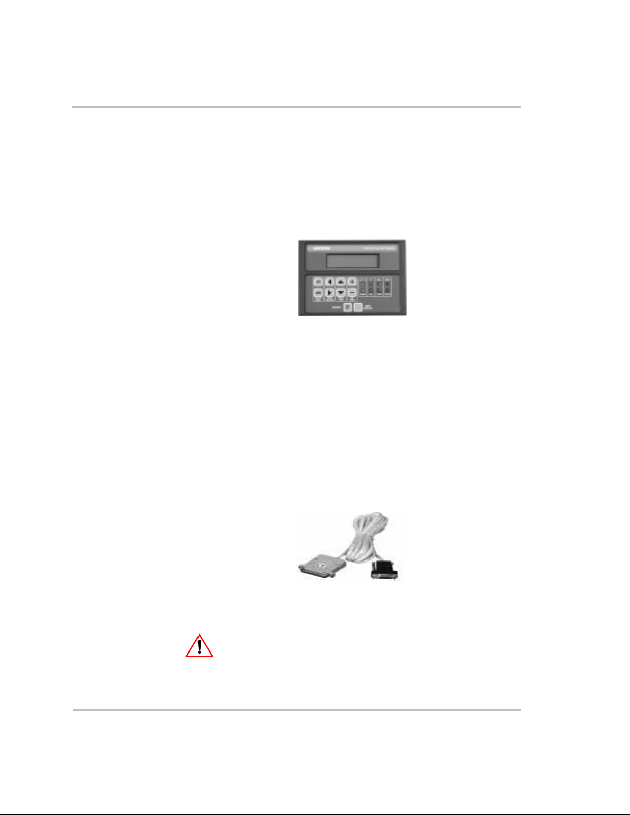
Inverter Control Module (ICM)
The ICM allows remote control, monitoring, and adjustment of all
inverter settings. The remote ICM comes with cables in lengths of 25 feet
(7.5 meters) or 50 feet (15 meters). The remote ICM duplicates all the
functions and controls of the ICM on the front panel of the unit.
For distances greater than that, see the Inverter Communications Adapter
(ICA).
Additional/Optional Equipment Considerations
Figure 2-9
This item is not provided with the inverter and must be purchased
separately.
Inverter Control Module
Inverter Communications Adapter (ICA)
The ICA allows the inverter to be connected directly to a PC for
monitoring and adjustment. The ICA comes with a 50 ft. cable. The ICA
can also be used up to 500 feet away, but additional cabling will be
needed and Xantrex does not provide longer cables at this time. It may
also be operated remotely with the addition of a modem at the inverter
site.
Figure 2-10
Inverter Communications Adapter
CAUTION: Damage to PC
Do not connect a PC to the inverter when it is configured in a
positive ground system. Damage to the PC and the inverter may
occur which is not covered under warranty.
976-0043-01-01 2–27
Page 62
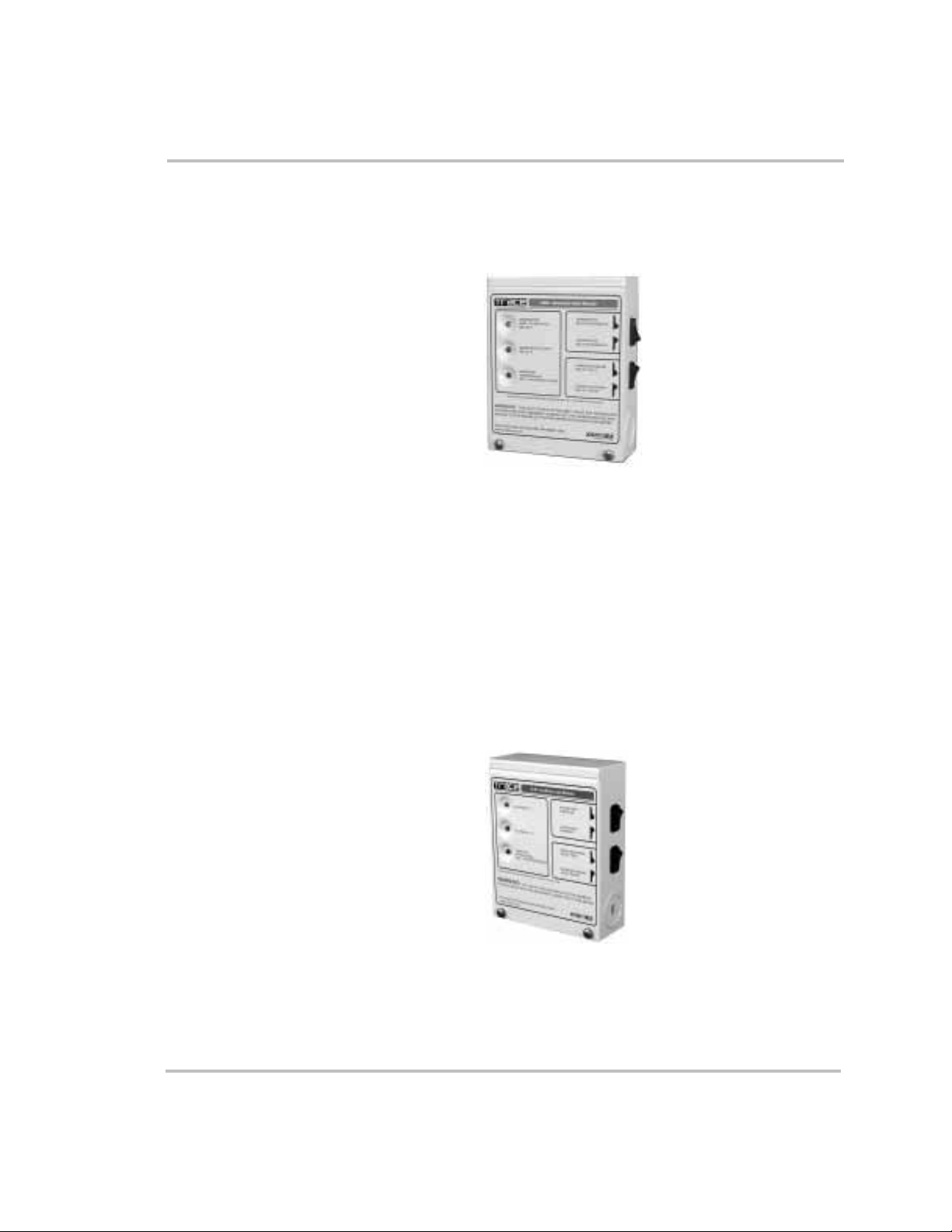
System Configuration
Generator Start Module (GSM)
The GSM is an accessory that enables the inverter to start and stop
generators equipped with auto-start features.
Figure 2-11
See “Generator Considerations” on page 2–19, for information on using
generators and Appendix D, “Generators” for additional information
regarding generator types.
Auxiliary Load Module (ALM)
The ALM is an accessory that enables the inverter to start and stop
auxiliary loads such as alarms, water pumps, or ventilation fans.
This item is not provided with the inverter and must be purchased
separately.
Generator Start Module
Figure 2-12
See “Auxiliary Load Module (ALM)” on page 3-42. for additional
information regarding connecting the Auxiliary Load Module to the
inverter.
2–28 976-0043-01-01
Auxiliary Load Module
Page 63
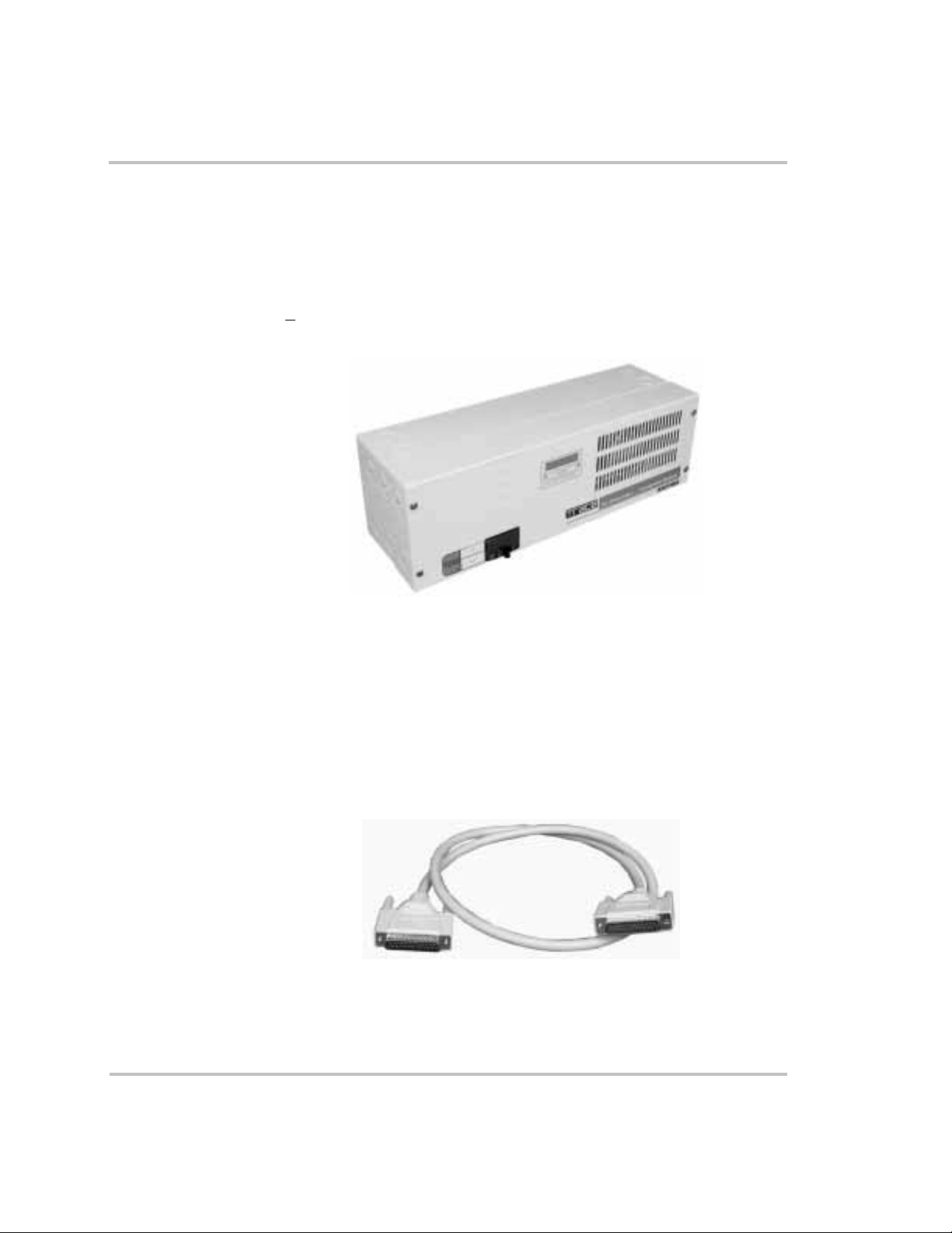
Additional/Optional Equipment Considerations
Autotransformer for 240 VAC Applications (T240)
The T240 allows a single inverter to increase it’s output voltage from
120 volts to 240 volts or it will take 240 Vac from a generator and “stepdown” the voltage to 120 Vac for the single inverter. For step-up and stepdown functions, two T240s will be required. Using a T240
Autotransformer optimizes the generator output of smaller generators
(<
8 kW) and improves charging time.
Figure 2-13
T240 Auto-transformer
Inverter Stacking Control – Series (ISC-S) Cable
The ISC-S cable is a special communications cable that allows two Sine
Wave Plus inverters to be connected together in “series” to provide power
to both 120 Vac loads and 240 Vac loads.
See the ISC-S Owner’s Guide for more information on stacked inverter
applications.
Figure 2-14
ISC-S Cable
976-0043-01-01 2–29
Page 64

System Configuration
Renewable Energy DC Input Sources
Renewable energy sources (e.g., photovoltaic (PV) arrays, wind turbines,
DC micro-hydro generators) can be used with the inverter to provide
power for all applications—off grid and on grid. However, in addition to
the actual RE equipment being used, other items may be needed to ensure
safety in the overall system.
Charge Regulation
using a Charge
Controller
Diversion Load
Control
Important:
national electric codes to determine what additional equipment may be
required for your installation.
Installations of this equipment should only be performed by skilled
personnel such as qualified electricians and Certified Renewable Energy
(RE) System Installers. For a list of Xantrex Certified RE dealers, please
visit our website at www.XantrexREdealers.com.
Note:
power connected to either of the AC inputs on the inverter/charger. The
Sine Wave Plus cannot control or regulate DC voltages from DC
sources. DC charge controllers must be used for all DC sources such as
PV arrays, wind turbines, and water turbines.
A charge controller must be used to regulate the charge supplied to the
batteries and prevents over-charging (or high battery conditions). A
charge controller prevents the batteries from exceeding a user-specified
voltage level. This preserves and extends the life of the battery by
preventing the damage caused by over-charging. The charge controller
can also take over the functions of bulk and equalize charging.
Wind turbines and hydro-electric generators may be damaged if the DC
loads are suddenly removed from them. This can happen if the DC
disconnect should open (trip) or the batteries are fully charged and no
other DC loads are connected in the system. A diversion load controller
prevents damage to the generator system by diverting the power from the
generator to a diversion load device. This keeps a load on the generator
and controls over-spin if the batteries should be disconnected. Refer to
the controller manual for proper types of diversion load devices.
Be sure to consult your authorized dealer and all local/
The “charger” built into the Sine Wave Plus is only for AC
2–30 976-0043-01-01
Page 65

Additional/Optional Equipment Considerations
Figure 2-15
Xantrex C-Series Charge Controllers
PVGFP The PV Ground Fault Protection (PVGFP) is designed to minimize the
possibility of a fire resulting from ground faults in a PV array (in
accordance with NEC for rooftop-mounted PV systems on dwellings). It
is not designed or intended to prevent electrical shock or to be used for
PV DC overcurrent.
Figure 2-16
976-0043-01-01 2–31
PV Ground Fault Protection (PVGFP)
Page 66

System Configuration
Off-Grid Applications
The Sine Wave Plus can be used as a primary source of AC power to
support off-grid, stand-alone systems where no utility power is available.
Sine Wave Plus applications in an off-grid situation include:
• renewable energy systems (with or without generator backup), and
• generator-only systems
• inverter only systems (charger in the inverter/charger is not used, but
batteries are maintained by an external DC charger).
Renewable Energy Systems with/without Generator Backup
In this configuration, the main power is generated by renewable energy
sources, such as solar, wind, micro-hydro or some other form of a
regulated DC charging source, and is stored in a battery bank. The Sine
Wave P lu s will operate all AC loads from the power stored in this battery
bank.
In the event that renewable energy sources are insufficient to power the
required loads or keep the batteries charged, a generator can be used to
supplement the system.
Single Inverter Configurations (120 Vac)
If only 120 Vac output is required from the system, a single inverter is
adequate to provide the required power, depending on the wattage
(output) requirements of the total system.
Single Inverter Configurations (120/240 Vac)
If 240 Vac output is required from the system and the total of the loads
does not exceed the wattage output of the inverter, a T240
Autotransformer can be added to the output of the system to increase the
voltage output.
See Appendix F, “Multiwire Branch Circuit Wiring”, for more
information on using single inverters with multi-wire branch circuits.
See Figure 2-17 for an example of both configurations (120 Vac and
240 Vac output) with all optional equipment. Disregard any part of this
illustration that does not apply to the components being installed. For
purposes of this publication, the main breaker (utility) panel is referred to
as the “inverter AC distribution panel” or simply “inverter panel”.
2–32 976-0043-01-01
Page 67

Off-Grid Applications
NOTES:
1. Always refer to your local electric codes for proper
wiring instructions.
2. For purposes of this illustration, the ground for the
AC generator is run through the inverter.
3. Separate grounding runs are shown in this
illustration to demonstrate a single point ground.
4. If using a PC to monitor the system, the Xantrex
ICA is required. If using a PC to monitor from offsite, an external modem is required at the inverter
site.
5. Ensure all the DC negatives in the system are
bonded to earth ground in only one place (single
point bond). If you are using a PVGFP, allow this
single “DC Negative to earth ground bond” to be
provided through the PVGVP.
6. If this is not a separately derived system (per the
NEC), the AC neutrals should be bonded to earth
ground in only one place.
Figure 2-17
Off-Grid Application – Renewable Energy System using a Single Inverter
976-0043-01-01 2–33
Page 68

System Configuration
Dual Inverter Configurations (240 Vac)
If 240 Vac power is required and the wattage required exceeds the wattage
output of a single inverter, it may be necessary to add a second inverter.
Two inverters can be “series” stacked to provide both 120 Vac and 240
Vac, 60 Hz, power to the AC loads.
Note:
This interface cable is connected to the series stacking port of the
inverters (see “Inverter Stacking Control – Series (ISC-S) Cable” on
page 2–29).
Series stacking is an excellent choice for providing power to multiwire
branch circuits where single (120 Vac) inverters may require extensive
rewiring within the building.
See Figure 2-18 for an example of this configuration with all options
shown. Disregard any part of this illustration that does not apply to the
system configuration being installed.
Series-stacking inverters require the use of the ISC-S cable.
2–34 976-0043-01-01
Page 69

Off-Grid Applications
NOTES:
1. Always refer to your local electric codes for proper
wiring instructions.
2. For purposes of this illustration, the ground for the
AC generator is run through the inverter.
3. Separate grounding runs are shown in this
illustration to demonstrate a single point ground.
4. If using a PC to monitor the system, the Xantrex
ICA is required. If using a PC to monitor from offsite, an external modem is required at the inverter
site.
5. Ensure all the DC negatives in the system are
bonded to earth ground in only one place (single
point bond). If you are using a PVGFP, allow this
single “DC Negative to earth ground bond” to be
provided through the PVGVP.
6. If this is not a separately derived system (per the
NEC), the AC neutrals should be bonded to earth
ground in only one place.
Figure 2-18
Off-Grid Application – Renewable Energy System using Dual Inverters
976-0043-01-01 2–35
Page 70

System Configuration
Generator-Only Systems
In these applications, an AC generator serves as the main AC source
when batteries are insufficient to power the loads. Both an AC and a DC
generator can provide a power source for the battery charger. With the aid
of the Xantrex GSM, the Sine Wave Plus can turn on automatically most
remote-starting generators, on demand.
See “Generator Considerations” on page 2–19 and Appendix D,
“Generators” for additional information regarding using generators for
system input.
Single-Inverter Configurations
A single-inverter system is usually adequate to power most 120 Vac
loads. If 240 Vac is required from the system and doesn’t exceed the
wattage output of a single inverter, a T240 auto-transformer can be added
to the output of the system to increase the voltage output.
See Figure 2-19 for an illustration of a 120 Vac Generator-Only System
using a single inverter. Disregard any part of this illustration that does not
apply to the system configuration being installed.
2–36 976-0043-01-01
Page 71

Off-Grid Applications
NOTES:
1. Always refer to your local electric codes for proper
wiring instructions.
2. For purposes of this illustration, the ground for the
AC generator is run through the inverter.
3. Separate grounding runs are shown in this
illustration to demonstrate a single point ground.
4. If using a PC to monitor the system, the Xantrex
ICA is required. If using a PC to monitor from offsite, an external modem is required at the inverter
site.
5. Ensure all the DC negatives in the system are
bonded to earth ground in only one place (single
point bond). If you are using a PVGFP, allow this
single “DC Negative to earth ground bond” to be
provided through the PVGVP.
6. If this is not a separately derived system (per the
NEC), the AC neutrals should be bonded to earth
ground in only one place.
Figure 2-19
Off Grid Generator-Only System using a Single Inverter
976-0043-01-01 2–37
Page 72

System Configuration
Dual Inverter Configurations
If 240 Vac power is required and the wattage required exceeds the wattage
output of a single inverter, it may be necessary to add a second inverter.
Two inverters can be “series” stacked to provide both 120 Vac and 240
Vac, 60 Hz, power to the AC loads.
Note:
This interface cable is connected to the series stacking port of the
inverters (see “Inverter Stacking Control – Series (ISC-S) Cable” on
page 2–29).
Series stacking is an excellent choice for providing power to multi-wire
branch circuits where single (120 Vac) inverters may require extensive
rewiring within the building.
See Appendix F, “Multiwire Branch Circuit Wiring” for information on
identifying and correcting Multi-wire branch circuit wiring.
See Figure 2-20 for an illustration of a 240 Vac Generator-Only System
using dual inverters
240 Vac-only Input Source
When using a 240 Vac-only input source (with a L1 and L2 connection
but no neutral) with a dual-inverter configuration, a neutral connection
needs to be provided from the 240 Vac source to the inverter’s common
neutral. A T240 Autotransformer proceeding the inverter’s input can be
used to meet this requirement.
Series-stacking inverters require the use of the ISC-S cable.
2–38 976-0043-01-01
Page 73

Off-Grid Applications
NOTES:
1. Always refer to your local electric codes for proper
wiring instructions.
2. For purposes of this illustration, the ground for the
AC generator is run through the inverter.
3. Separate grounding runs are shown in this
illustration to demonstrate a single point ground.
4. If using a PC to monitor the system, the Xantrex
ICA is required. If using a PC to monitor from offsite, an external modem is required at the inverter
site.
5. Ensure all the DC negatives in the system are
bonded to earth ground in only one place (single
point bond). If you are using a PVGFP, allow this
single “DC Negative to earth ground bond” to be
provided through the PVGVP.
6. If this is not a separately derived system (per the
NEC), the AC neutrals should be bonded to earth
ground in only one place.
Figure 2-20
Off Grid Application – Generator-Only System using Dual Inverters (Series-Stacked)
976-0043-01-01 2–39
Page 74

System Configuration
On-Grid Applications
The Sine Wave Plus can be combined with utility power to provide
backup power in the event of a primary power source failure. It can use
utility power to backup renewable energy systems. It can use renewable
energy and/or a generator to backup utility grid power. It can be used as
an energy management tool to optimize energy consumption.
Backup Systems
Renewable Energy
Backup (BX mode)
Utility Backup
(SB mode)
This configuration uses renewable energy sources as the primary source
of power to operate the AC loads and grid power as an automatic backup
source.
In this configuration, the utility grid is the main source of power. The
energy stored in the batteries only provide backup power in the event of a
grid failure. Batteries can be charged by the utility grid when available,
RE sources, or with a backup generator.
Single Inverter Configurations (120 Vac)
If only 120 Vac output is required from the system, a single inverter is
adequate to provide the required power, depending on the wattage
requirements of the total system.
See Appendix F, “Multiwire Branch Circuit Wiring”, for information on
multi-wire branch circuits.
Single Inverter Configurations (240 Vac)
If 240 Vac output is required from the system and the total of the loads
does not exceed the wattage output of the inverter, a T240
Autotransformer can be added to the output of the system to increase the
voltage output.
See Figure 2-21 for an example of a single inverter configuration for
either 120 Vac or 120/240 Vac output. Disregard any part of this
illustration that does not apply to the system configuration being installed.
2–40 976-0043-01-01
Page 75
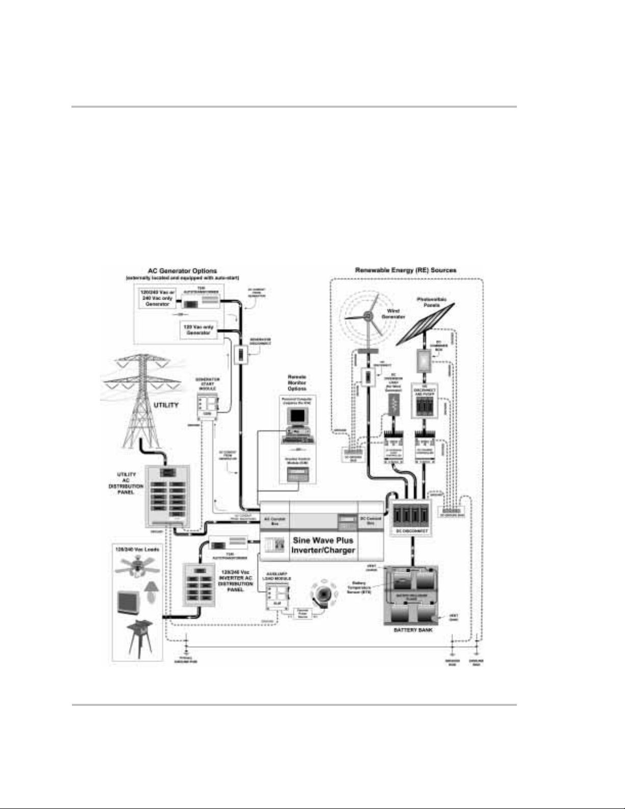
On-Grid Applications
NOTES:
1. Always refer to your local electric codes for proper
wiring instructions.
2. For purposes of this illustration, the ground for the
AC generator is run through the inverter.
3. Separate grounding runs are shown in this
illustration to demonstrate a single point ground.
4. If using a PC to monitor the system, the Xantrex
ICA is required. If using a PC to monitor from offsite, an external modem is required at the inverter
site.
5. Ensure all the DC negatives in the system are
bonded to earth ground in only one place (single
point bond). If you are using a PVGFP, allow this
single “DC Negative to earth ground bond” to be
provided through the PVGVP.
6. If this is not a separately derived system (per the
NEC), the AC neutrals should be bonded to earth
ground in only one place.
Figure 2-21
On-Grid Application – Backup System using a Single Inverter
976-0043-01-01 2–41
Page 76

System Configuration
Dual Inverter Configurations (240 Vac)
If 240 Vac power is required and the wattage required exceeds the wattage
output of a single inverter, it may be necessary to add a second inverter.
Two inverters can be “series” stacked to provide both 120 Vac and
240 Vac, 60 Hz, power to the AC loads.
Note:
This interface cable is connected to the series stacking port of the
inverters (see “Inverter Stacking Control – Series (ISC-S) Cable” on
page 2–29).
Series stacking is an excellent choice for providing power to multiwire
branch circuits where stand-alone (120Vac) inverters may require
extensive rewiring within the building.
See Appendix F, “Multiwire Branch Circuit Wiring” regarding Multi-wire
branch circuits
See Figure 2-22 for an example of this configuration showing all the
optional equipment. Disregard any part of this illustration that does not
apply to the system configuration being installed.
Series-stacking inverters require the use of the ISC-S cable.
2–42 976-0043-01-01
Page 77

On-Grid Applications
NOTES:
1. Always refer to your local electric codes for proper
wiring instructions.
2. For purposes of this illustration, the ground for the
AC generator is run through the inverter.
3. Separate grounding runs are shown in this
illustration to demonstrate a single point ground.
4. If using a PC to monitor the system, the Xantrex
ICA is required. If using a PC to monitor from offsite, an external modem is required at the inverter
site.
5. Ensure all the DC negatives in the system are
bonded to earth ground in only one place (single
point bond). If you are using a PVGFP, allow this
single “DC Negative to earth ground bond” to be
provided through the PVGVP.
6. If this is not a separately derived system (per the
NEC), the AC neutrals should be bonded to earth
ground in only one place.
Figure 2-22
On-Grid Application – Backup System using Dual Inverters, Series-stacked
976-0043-01-01 2–43
Page 78

System Configuration
Energy Management
The Sine Wave Plus can be programmed to control how and when to use
utility power. Advanced features allow for peak load management and
time-of-use billing. Utility management features also allow the Sine Wave
Plus to use renewable energy sources on a first priority basis and use
utility power as a last resort.
See “21 Grid (AC1) Usage Menu” on page 7–11 for more information
about programming these applications.
RE Backup with Utility (SB Mode)
In Standby (SB) Mode, the Sine Wave Pluss will automatically use power
from a DC source (i.e., RE) over grid power even when the inverter
shows it is “charging” from the grid.
When you have excess DC power from the RE source, the inverter will
automatically reduce the current draw from the grid and power the loads
from RE generated power.
During a time when loads exceed what the RE can provide, the inverter
will automatically bring in enough AC power from the grid to power the
loads.
See “SB (Standby) - Utility Backup” on page 7–12 for instructions for
setting these parameters.
Peak Load Management
To reduce utility peak demand charges, the inverter can be configured to
limit the maximum draw the AC loads place on the utility. Many utilities
impose a surcharge on their customers based on the peak load used by a
facility. The inverter can be used to provide power above a specified
level, eliminating the surcharge. When the utility current draw reaches the
maximum level, the inverter assists by providing battery powered AC to
the loads.
See “13A Grid (AC1) Amps AC” on page 6–23 for instructions for
setting these parameters.
For Peak Load Shaving to be effective, all loads must be connected to the
inverter. For large loads, multiple (or stacked) inverters may be required.
To further ensure the batteries are able to supplement the power
requirements of the connected load, an additional source of power (solar,
wind or hydroelectric) is recommended.
Peak Load Shaving can also be used in addition to the Time-of-Use
(TOU) metering.
2–44 976-0043-01-01
Page 79
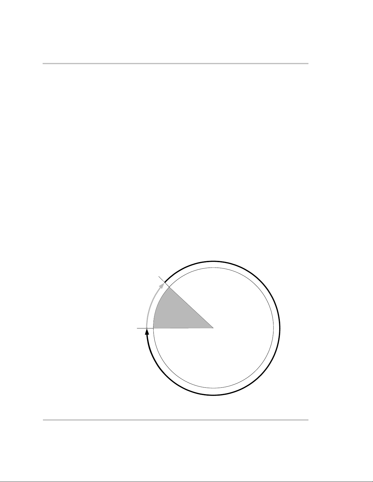
Time-of-Use (TOU) Metering
Utilities use TOU metering to determine utility charges during peak usage
hours and to impose a surcharge. The inverter can be configured to
overcome these peak charges by using a battery (or battery bank) to store
energy during the inexpensive energy hours and consumes the battery
energy during expensive energy hours.
When in this mode, the inverter is programmed to only use utility power
during user-specified times during the day. This helps the consumer take
advantage of lower utility rates by using power from the battery bank
during times that utility power is most expensive.
See “21 Grid (AC1) Usage Menu” on page 7–11 for instructions for
setting these parameters.
Energy management determines when utility power is used. Start and
Stop times are programmed into Menu Items 21B and 21C depending on
when you want the inverter to use utility power.
In the example below, Figure 2-23 shows the inverter disconnects from
the utility grid at 6:00 PM and supports the connected load from batteries.
It continues to run until 9:00 PM. It then reconnects to the utility grid,
passing AC through to the connected load, and begins maintaining the
batteries based on the battery charger settings in the Basic Setup Menu
(Float or Silent).
On-Grid Applications
00
Figure 2-23
23
22
21
GRID USAGE BEGIN
TIME 21:00 (9 PM)
20
OPERATING
FROM INVERTER
19
DURING PEAK
UTILITY PERIOD
18
GRID USAGE END
TIME 18:00 (6 PM)
17
16
15
14
13
Time-of-Use Metering
1
OPERATING FROM
UTILITY GRID AND
BATTERY CHARGING
11
12
2
3
4
5
6
7
8
9
10
976-0043-01-01 2–45
Page 80

System Configuration
When using the system for TOU metering, the system should be designed
with a battery capacity large enough to support the load during the entire
peak rate period without reaching the 11C Low Battery Cut Out VDC
voltage.
To further ensure the batteries are able to support the load, an additional
source of power (solar, wind or hydroelectric) is recommended.
Depending upon the capacity of the system, certain heavy loads should
only be run during non-peak periods.
AC Load Support
Note:
VDC voltage, the inverter will automatically reconnect to the utility grid
to maintain the connected load.
Note:
energy system. Often these systems will provide their peak output at the
high billing times. Battery power used to supplement the renewable
energy used during peak times is replenished during non-peak times.
This feature allows power to be automatically drawn from the batteries to
assist either the utility grid or an AC generator support heavy loads (i.e.,
loads that exceed the available current from either the generator or the
utility grid). When the grid or generator requires additional AC current to
support the loads, current is drawn from the batteries.
Generators have a limited output current, and it is possible to reach this
limit when operating heavy loads. The Sine Wave Plus is designed to
assist the generator when heavy current demands load down the generator
by supplying additional power from the batteries. In this way, the
generator can operate loads heavier than it would otherwise be capable of
running. When the inverter is in this mode, the batteries are not charging
even though the LED indicators on the inverter may indicate the charge
mode is on.
In addition, the battery charger can back off its charging current to the
batteries so the combined load of the charger and load support does not
load down the generator or trip its output breakers or fuses.
In the event the batteries reach their 11C Low Battery Cut Out
TOU mode is usually used in conjunction with a renewable
AC support parameters are controlled by the 13A Grid (AC1) Amps AC
and or 13B Gen (AC2) Amps AC depending on the application.
2–46 976-0043-01-01
Page 81

UTILITY or GENERATOR + INVERTER
SUPPORT V OLTAGE (from battery)
On-Grid Applications
Utility Grid or
AC Generator
Figure 2-24
Note:
Running and Start-up (Peak) currents are limited to the
INVERTER/CHARGER
AC
AC Support Mode
AC
DC
BATTERY
HEAVY
AC LOAD
maximum current limits of the inverter.
Note:
In the AC support mode, the BULK or FLOAT charge indicator
LEDs may be ON even though the batteries are draining. Use the
04 Meters Menu heading and 04C INV/CHR Amps AC menu item to
view the actual amperage. A negative reading indicates the inverter is
supporting the generator from the batteries.
See “21 Grid (AC1) Usage Menu” on page 7–11 for instructions on
setting these parameters.
Renewable Energy with Grid Backup (BX Mode)
To have the inverter operate independently of the grid but use the grid in
times of low battery voltage, the inverter can be set up in the "BX" mode.
In this mode, the inverter powers the AC loads using the RE sources and
only uses AC power from the grid to run the loads when the battery
voltage drops below user-specified levels.
When the batteries have recharged to a specified voltage by the renewable
energy sources, the inverter transfers from the utility grid to inverter
supplied AC power.
See “22 Battery Xfer (BX) Menu” on page 7–13 for instructions for
setting these parameters.
976-0043-01-01 2–47
Page 82

2–48
Page 83

3
Installation
Chapter 3, “Installation” describes how to mount and install
the Sine Wave Plus Inverter/Charger and perform cabling
procedures for various configurations.
Page 84

Installation
Pre-Installation
Before installing the Sine Wave Plus, read all instructions and cautionary
markings located in this manual.
Installations should meet all local codes and standards and be performed
by qualified personnel, such as a licensed electrician.
Tools Required
Important:
prior to starting this installation.
Installations of this equipment should only be performed by skilled
personnel such as qualified electricians and Certified Renewable Energy
(RE) System Installers. For a list of Xantrex Certified RE dealers, please
visit our website at www.XantrexREdealers.com.
The Sine Wave Plus is heavy. Always use proper lifting techniques during
installation to prevent personal injury.
Although the DC electrical system may be “low voltage”, significant
hazards may still be present, particularly from short-circuits of the battery
system. Inverter systems, by their nature, involve power from multiple
sources (inverter, generator, utility, batteries, solar arrays, etc.) that add
hazards and complexity that can be very challenging.
The following tools may be required for installing this equipment.
❐ Assorted Phillips screw drivers
❐ Level
❐ Slotted screw driver
Be sure to obtain the appropriate permits, if necessary,
❐ Wire strippers
❐ Assorted open-end wrenches
❐ Torque wrench
❐ Socket wrench and sockets
❐ Electrical tape
❐ Multi meter (AC/DC volts)
❐ Pencil
❐ Hole saw
❐ Utility knife
3–2 976-0043-01-01
Page 85

Hardware / Materials Required
The following materials may be required for completing this installation.
❐ 4' x 8' sheet of ¾" plywood for mounting
❐ 2 x 4 boards for mounting
❐ #10 and/or #12 wood screws (or ½" x 1¼" lag bolts)
❐ Conduits and appropriate fittings for wire runs (e.g. wire nuts)
❐ Electrical wire of appropriate size and length
❐ Battery Cable lugs (depending on types of battery cables used)
❐ Breaker Panels
❐ Ground busses, bars, and/or rods
Optional System Accessories
The following optional system accessories can be used in the installation
of the Sine Wave Plus. These accessories are available from any
authorized Xantrex dealer. Consult with your local system designer to
determine what optional equipment will be needed for your specific
installation.
Pre-Installation
Conduit Boxes
Battery Cables
DC Disconnects and
Fuses
❐ ACCB with input/output/bypass breakers
❐ DCCB
❐ BC1.5 (Single) Battery Interconnects
❐ BC2/0 AWG (Pair), available in 5 and 10 foot lengths
❐ BC4/0 AWG (Pair), available in 5, 10, and 15 foot lengths
❐ DC175 (175 Amp DC Disconnect with Bonding Bar)
❐ DC250 (250 Amp DC Disconnect with Bonding Bar)
❐ TFB 200 (200 Amp Class-T Fuse)
❐ TFB 300 (300 Amp Class-T Fuse)
❐ TFB 400 (400 Amp Class-T Fuse)
❐ PV Ground Fault Projection (PVGFP1, PVGFP2, PVGFP3,
PVGFP4)
976-0043-01-01 3–3
Page 86

Installation
Remote Monitors
Generator Starting
Auxiliary Loads
Charge Controllers
Battery Status
Meter
“Series” Stacking
Cable
❐ ICM/25 (Inverter Control Module with 25 foot cable connection)
❐ ICM/50 (Inverter Control Module with 50 foot cable connection)
❐ ICA (Inverter Communications Adapter with 50 foot cable), for use
with your computer. Can be used with a modem on site. Modem
required for distances greater than 50 feet.
❐ Generator Start Module (GSM)
❐ Auxiliary Load Module (ALM)
❐ C-Series Charge Controllers (C35, C40, C60)
❐ TM500A Battery Status Meter
❐ ISC-S Cable
Battery Bank Preparation
Important:
the battery polarity on the DC input connections will cause permanent
damage to the inverter which is not covered under warranty. Always
check polarity BEFORE making connections to the inverter
The inverter is not reverse polarity protected. Reversing
You should have read the section titled “Battery Considerations” on
page 2–10 in the previous chapter before starting this procedure. For more
information, see Appendix C, “Battery Information”.
Prepare the battery bank as follows:
1. Determine the type of batteries to be used for the installation.
See “Battery Types” on page C–2 in Appendix C for information on
types of batteries and their applications.
2. Determine the appropriate battery bank size and battery configuration
for the installation.
See “Battery Requirements for Dual Inverter Systems” on page 2–15
for information on stacked (dual) inverter systems.
See “Battery Bank Sizing” on page C–4 for additional information on
calculating battery bank size and “Battery Configurations” on
page C–9 for information about how to wire the selected battery
configuration.
3–4 976-0043-01-01
Page 87

Pre-Installation
3. Determine the correct size of battery cables to use for installation.
See Table 2-2, “Minimum Required Battery Cable Size Versus
Length” on page 2–14 for additional information and recommended
battery cable sizing.
4. Determine the correct size of DC breaker/fuse to use for installation.
See Table 2-3, “Battery Cable to Maximum Breaker/Fuse Size” on
page 2–15 for additional information and recommended DC breaker/
fuse sizing.
5. Color code the cables with tape or heat shrink tubing. The standard
colors for DC cables are red for positive (+) and black for
negative (–).
Important:
requirements of the inverter. To determine the correct voltage for the
system, check the last two digits on the inverter’s model number. For
example, the Sine Wave Plus 2524 is a 24-volt inverter and requires a
24 Vdc battery system.
The battery voltage MUST match the voltage
Unpacking and Inspecting the Inverter
WARNING: Personal Injury Hazard
Do not attempt to mount this unit on the wall by your self as the
unit is too heavy for one person.
Have additional help available to assist in lifting the unit during
installation.
❐ Carefully unpack the Sine Wave Plus from its shipping carton.
❐ Inspect for shipping damage and contact the shipping company if
there is damage.
❐ Verify that all of the following items are present. Please call your
authorized Xantrex dealer if any items are missing.
•The Sine Wave Plus Inverter/Charger
•The Sine Wave Plus Inverter/Charger Owner’s Guide
• The Battery Temperature Sensor
• Battery Terminal Covers (with associated hardware).
❐ Save your proof-of-purchase. This is required if the unit should need
warranty service.
976-0043-01-01 3–5
Page 88

Installation
❐ Save the original shipping carton and packing materials. If the
inverter ever needs to be returned for service, it should be shipped in
the original carton. This is also a good way to protect the inverter if it
ever needs to be moved.
❐ Record the unit’s model number, serial number, and date-of-purchase
in the appropriate locations provided on page I–5 in the Warranty and
Product Information section at the back of this manual.
• Model Number information can be found on the Certification
Label located on the AC end of the unit. See Figure 3-1 for the
location of the this label.
• Serial Number information can be found on the Serial Number
Sticker located on the inverter rail adjacent to the AC side dual
knockouts and terminal access cover. See Figure 3-2, “Serial
Number Sticker and Knockout Locations and Sizes” on page 3–7
for the location of this sticker.
Serial
Number
(on rail)
AC End of the Inverter
Figure 3-1
3–6 976-0043-01-01
Certification Label Location
Page 89

Pre-Installation
Important:
The exclamation symbol below the CSA logo on the
certification label indicates the need to add overcurrent protection. It shall
be installed at the battery as part of the installation in accordance with
your local electrical code. Table 2-3, “Battery Cable to Maximum
Breaker/Fuse Size” on page 2–15 specifies the type and rating of the
overcurrent protection needed.
Serial
Number
Sticker
3/4 and 1”
Dual-knockouts
Figure 3-2
3/4 and 1”
Dual-knockouts
Serial Number Sticker and Knockout Locations and Sizes
Knockout Preparation
Remove your choice of knockouts from the chassis to facilitate conduit
installation for wire runs. This is much easier to do prior to mounting the
inverter. Figure 3-2 shows the locations and sizes of chassis knockouts.
976-0043-01-01 3–7
Page 90

Installation
Mounting
WARNING: Personal Injury Hazard
Do not attempt to mount this unit on the wall by yourself.
Have additional help available to assist in lifting the unit during
installation.
The Sine Wave Plus can be either shelf-mounted or wall-mounted. Be
sure to use appropriate lifting techniques and have extra people available
to assist in lifting the inverter into position while it is being secured. Also
make sure the supporting surface is strong enough to support the weight
of the inverter.
Refer to “Location Considerations” on page 2–4 for information on
proper location of the Sine Wave Plus.
Be sure to use all ten mounting holes in addition to the four keyhole slots
provided for mounting. Just using the keyhole slots will not be sufficient
to safely mount the inverter.
Shelf-Mounting
To mount the Sine Wave Plus on a shelf, follow the instructions below.
1. Ensure that the desired shelf location is strong enough to support the
inverter weight and allows adequate clearance for ventilation and
access to the indicators and controls.
2. Drill mounting holes in the shelf by one of the following methods. Be
sure to use all of the inverter mounting holes and keyhole slots for
mounting.
a) Using the measurements from Figure 3-3 drill out the mounting
hole locations for the inverter.
b) Create a cardboard template by tracing around the inverter and
marking the mounting holes and keyhole slots on the cardboard.
Use the cardboard template to locate and drill the mounting holes.
3. Test the strength of the shelf before mounting the inverter on it.
4. With assistance, lift the inverter into position and install it onto the
shelf, using appropriately sized lag bolts and washers.
3–8 976-0043-01-01
Page 91
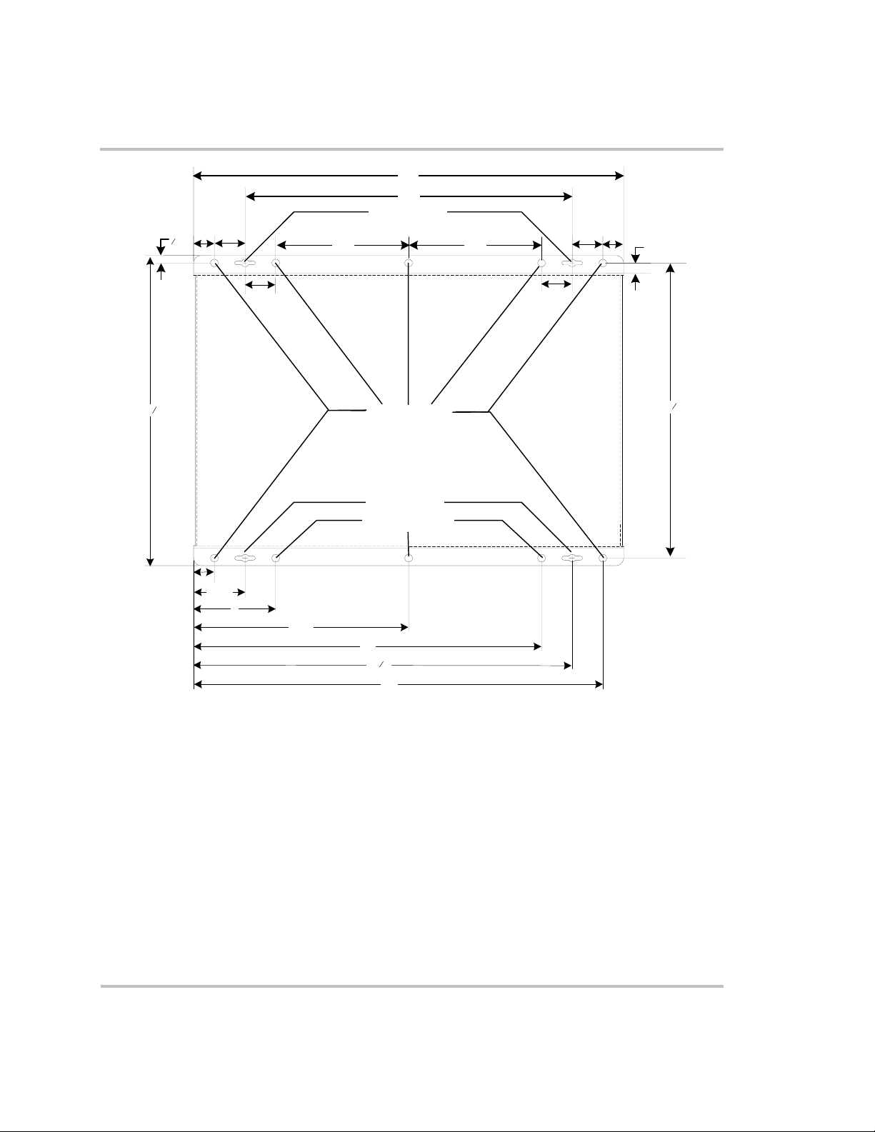
Pre-Installation
21"
16"
Keyhole slots
1½"
1"
3
8
"
6-½" 6½"
1" 1½"
½"
15 "
1½"
1
8
Mounting Holes
1½"
14 "
3
8
Size = 0.375" diameter
Keyhole slots
Mounting Holes
1"
2½"
4
10½"
17"
3
8
"
18
20"
***NOT TO SCALE***
Figure 3-3
976-0043-01-01 3–9
Dimensional Drawing
Page 92

Installation
Wall-Mounting
Wall Mounting
using 2 x 4’s
Wallboard is not strong enough to support the weight of the inverter, so
additional support must be added. This can be in the form of reinforcing
2 x 4’s or a half sheet (4 ft x 4 ft) of ¾-inch plywood.
The easiest method for securing the inverter to an existing wall is to place
two 2 x 4’s horizontally on the wall (spanning at least three studs) and
securing the inverter to the 2 x 4’s.
To mount the Sine Wave Plus on a wall, follow the instructions below.
1. Locate the studs and mark their location on the wall.
2. Measure the desired height from the floor for the inverter to be
mounted. The height should place the inverter’s control module at the
operator’s eye level for easy viewing and setting.
3. Using a level, run a horizontal line. The length of the line must span
at least 3 studs.
4. Place a pre-cut 2 x 4 on the marked location and drill pilot holes
through the 2 x 4’s and studs.
5. Secure the 2 x 4 with #10 wood screws (length to penetrate 1½ inches
or more into the studs).
6. Secure the 2 x 4 and repeat the procedure for the remaining 2 x 4
(paint the 2 x 4’s, if desired, to match the surrounding wall).
7. Drill mounting holes in the 2 x 4 mounting rails by one of the
following methods. Be sure to use all of the inverter mounting holes
and keyhole slots for mounting.
a) Using the measurements from Figure 3-3 drill out the mounting
hole locations for the inverter.
b) Create a cardboard template by tracing around the inverter and
marking the mounting holes and keyhole slots on the cardboard.
Use the cardboard template to locate and drill the mounting holes.
8. Ensure that the 2 x 4’s are securely fastened to the wall before
mounting the inverter to them.
9. With assistance, lift the inverter into position and install it onto the
2 x 4’s using ¼ x 1½-inch lag bolts and washers.
3–10 976-0043-01-01
Page 93
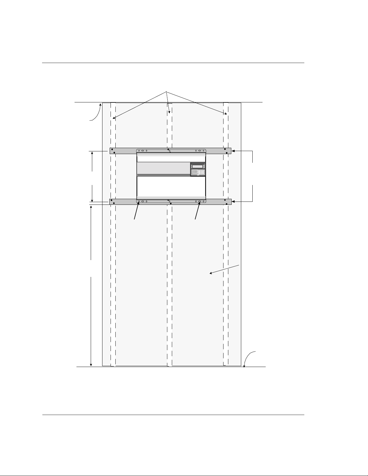
Ceiling
14–3/8"
c-c
Wall studs 16 inches
on center
Sine Wave Plus
Inverter/C harger
Set Inverter
OFF SRCH ON CHG
Pre-Installation
2 x 4
mounting
supports
Figure 3-4
M ounting
Holes (10 )
Approx .
4–5 ft
Wall-Mounting Method using 2 x 4’s
Keyhole Slots
(4)
Wallboard
Floor
976-0043-01-01 3–11
Page 94

Installation
Wall Mounting
using Plywood
Alternatively, a half sheet (4 ft x 4 ft) of ¾-inch plywood can also be used
as a backing, with the inverter mounted directly to the plywood using ¼inch diameter lag bolts and washers. The plywood must span three studs
for adequate support.
1. Drill the mounting holes in the plywood sheet by one of the following
methods. Be sure to use all the mounting holes and keyhole slots for
mounting.
a) Using the measurements from Figure 3-3 drill out the mounting
hole locations for the inverter.
b) Create a cardboard template by tracing around the inverter and
marking the mounting holes and keyhole slots on the cardboard.
Use the cardboard template to locate and drill the mounting holes.
2. Ensure the plywood is securely fastened to the wall before mounting
the inverter on it.
3. With assistance, lift the inverter into position and install it onto the
plywood using ¼ x ¼-inch lag bolts and washers.
3–12 976-0043-01-01
Page 95
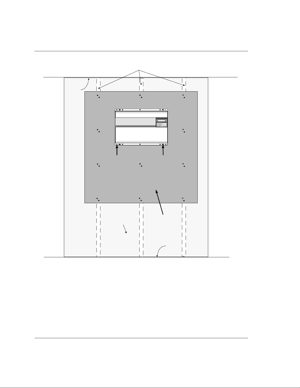
Ceiling
Wall studs 16 inches
on cent er
Sine Wave Plus
Inverter/Charger
Set Inverter
OFF SRCH ON CHG
Pre-Installation
Figure 3-5
Mounting
Holes (10)
Wallboard
Wall Mounting using Plywood
Keyh ole
Slots (4)
Plywood
Floor
976-0043-01-01 3–13
Page 96

Installation
DC Wiring
DC wiring includes the following steps (described in the following
locations).
❐ “Preparing the Battery Bank” on page 3–14
❐ “Grounding the DC System” on page 3–15
❐ “Connecting DC Input Sources – Renewable Energy Configurations”
on page 3–18
❐ Providing over-charge protection. See “Over-voltage Protection
using a Charge Controller” on page E-2.
❐ Providing diversion loads if necessary. See “Diversion Load
Control” on page E-3.
❐ “Installing the Battery Temperature Sensor (BTS)” on page 3–18
❐ “Connecting the Batteries to the Inverter” on page 3–20
WARNING: Shock Hazard
Preparing the Battery Bank
Prepare the battery bank according to type of battery selected and
configure the battery bank to optimize voltage output according to system
requirements. See your battery manufacturer’s installation guide for
recommendations.
See Appendix C, “Battery Information” for additional information on
determining battery bank type and configuration.
Run the positive and negative battery cables as close to each other as
possible by taping them together after all the connections are made. This
reduces the effects of inductance, improves surge capacity and reduces
RFI and EMI emissions.
Install a DC disconnect between the battery bank and the inverter.
Following the manufacturer’s installation instructions.
Ensure that all AC and DC breakers are switched OFF before
connecting or disconnecting the battery cables and that all
sources of power (both AC and DC) are disconnected from the
inverter’s inputs.
3–14 976-0043-01-01
Page 97

Grounding the DC System
The inverter’s chassis ground lug (see Figure 3-6) is used to connect the
chassis of the inverter to the DC grounding system. The terminal accepts
wires from #14 AWG to #2 AWG.
DC Wiring
WARNING: Fire Hazard
Undersized cables can overheat and melt creating a fire hazard
when subjected to heavy (peak) loads. Always use a properly
sized cable and length rated for the amperage of the inverter and
batteries.
WARNING: Shock Hazard
Always attach ground leads before attaching AC or DC power
connections.
Chassis
Ground Lug
DC End of Inverter
Figure 3-6
The Xantrex DC175 and DC 250 have optional grounding blocks to
simplify grounding procedures and can be used as the DC disconnect as
shown in Figure 3-7 on page 3–16.
976-0043-01-01 3–15
Chassis Ground Lug Location on Inverter DC End
Page 98

Installation
Single Inverter
To ground a single inverter:
1. Connect the ground bond in the DC disconnect to the primary
grounding electrode, in accordance with local and national electrical
codes.
2. Connect the NEGATIVE (–) terminal of the battery bank to the
ground bond inside the DC disconnect.
3. Connect an appropriately sized GROUND wire from the Chassis
Bonding Lug on the inverter DC end to the ground bond inside the
DC disconnect.
Figure 3-7
3–16 976-0043-01-01
DC Grounding of a Single Inverter
Page 99

DC Wiring
Dual Inverters
To ground a dual inverter configuration:
1. Connect the ground bond in the DC disconnect between the inverters
and the batteries to the primary grounding electrode, in accordance
with local and national electrical codes.
2. Connect the NEGATIVE (–) terminal of the battery bank to the
ground bond inside the DC disconnect.
3. Connect an appropriately sized GROUND wire from the Chassis
Bonding Lug on the L1 inverter DC end to the ground bond inside the
DC disconnect.
4. Connect an appropriately sized GROUND wire from the Chassis
Bonding Lug on the L2 inverter DC end to the ground bond inside the
DC disconnect.
Figure 3-8
976-0043-01-01 3–17
DC Grounding of Dual Inverters
Page 100

Installation
Connecting DC Input Sources – Renewable Energy Configurations
Renewable energy sources (e.g., PV arrays, wind turbines etc.) may
require additional equipment such as charge controllers, diversion load
controllers, PV Ground Fault Protection and additional fuses and/or
disconnects. Since every configuration is unique, specific installation
instructions can not be provided. Follow your manufacturer’s instructions
for installation of these components.
Be sure to consult your local authority to ensure code compliance for your
configuration.
Installing the Battery Temperature Sensor (BTS)
Install the BTS on the side of the battery below the electrolyte level as to
measure the average battery temperature. If using multiple charging
devices (inverters and charge controllers), install all BTSs together with
each other so they all measure the same temperature. It is best to mount
the sensor(s) between the batteries in an insulated box to reduce the
influence of the ambient temperature outside the battery enclosure.
Ventilate the battery box at the highest point to prevent hydrogen
accumulation.
To install the BTS, follow the steps below.
1. Run the BTS wire in the DC conduit (if used) and route the RJ11
connector end (via one of the knockouts) to the BTS port located on
the DC end of the inverter.
2. Secure the sensor to one of the batteries located in the center of the
battery pack.
3. If other devices are using BTSs, place all of them on the same battery
so that they all measure the same temperature.
3–18 976-0043-01-01
 Loading...