

Page 1
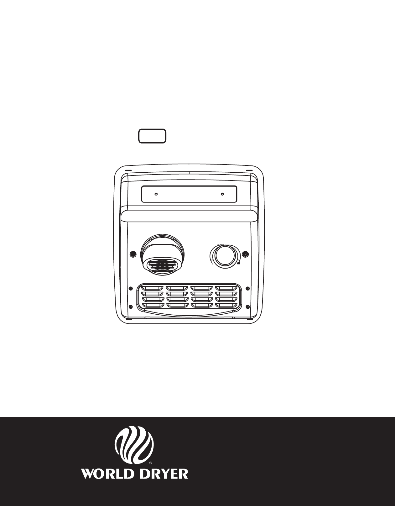
Model A Recessed
ADA Compliant Heavy Duty Hand Dryer
Secamanos Empotrado Resistente Modelo A Compatible con ADA
Sèche-mains robuste à montage encastré, modèle A, conforme ADA
All XRA, RA Series
Todos los Modelos de las Series XRA y RA
Toutes les modèles de série XRA et RA
Please read and save these instructions. Read carefully before attempting to assemble, install, operate or service
the product described. Protect yourself and others by observing all safety information. Failure to comply with
instructions could result in personal injury and/or property damage. Retain instructions for future reference.
Por favor lea y guarde estas instrucciones. Léalas cuidadosamente antes de tratar de montar, instalar, operar o dar mantenimiento al producto aquí
descrito. Protéjase usted mismo y a los demás observando toda la información de seguridad. No seguir las instrucciones puede ocasionar daños,
tanto personales como materiales. Guarde estas instrucciones para referencia en el futuro.
Lire et conserver ces instructions. Les lire attentivement avant de commencer à assembler, installer, faire fonctionner, réparer ou entretenir l’appareil
décrit. Pour se protéger et protéger autrui, observer toutes les consignes de sécurité. Le fait de négliger d’appliquer ces instructions peut entraîner
des blessures et/ou des dommages matériels. Conserver ces instructions pour consultation ultérieure.
World Dryer Corporation
5700 McDermott Drive
Berkeley, IL 60163 U.S.A.
800-323-0701
www.worlddryer.com
1
Page 2
Description
World Dryer recess mounted, ADA compliant warm air hand dryer, powered by a high speed universal motor, delivering 2300 Watts
of drying power. This hand dryer runs on 115 Volts AC, 208/220-240 Volts AC, or 277 volts AC electrical supply, depending on
model. Automatic and push-button models are represented in this product group. This appliance is intended for use in hand drying,
contributing to hygienic and cost effective hand sanitation. This hand dryer may be used in commercial, industrial, ofce and public
facility environments.
General Specications
Basic Models Nozzle Drying Cycle Dimensions (WxDxH) Weight Cover Material
DXRA Fixed Automatic 13.1” x 13.8” x 4”
XRA Fixed Automatic 13.1” x 13.8” x 4”
RA Fixed* 30 Seconds 13.1” x 13.8” x 4”
(*) Rotating Nozzle Option
333 mm x 351 mm x 102 mm 26.5 lbs / 12 kgs Stainless Steel
333 mm x 351 mm x 102 mm 35 lbs / 15.9 kgs Cast Iron
333 mm x 351 mm x 102 mm 35 lbs / 15.9 kgs Cast Iron
Electrical Specications
Models Type Electrical Input Amperage Watts
(D) XRA5 Automatic 115 VAC, 60 Hz 20 2300
RA5 Push-button 115 VAC, 60 Hz 20 2300
(D) XRA54 Automatic 208-230 VAC, 60 Hz 10 2300
RA54 Push-button 208-230 VAC, 60 Hz 10 2300
(D) XRA548 Automatic 220-240 VAC, 50 Hz 10 2300
RA548 Push-button 220-240 VAC, 50 Hz 10 2300
(cULus Listed, E19860, CE TUV-GS)
General Safety Information
• Always disconnect the power source before servicing or installing the hand dryer.
DANGER
DANGER
• This hand dryer must be properly grounded (Earthed) for safe operation. An identied ground connection point is supplied on the
hand dryer’s wall base.
• We recommend GFCI protection in wet or damp locations or as required by local code.
WARNING
• Use only the electrical power (voltage and frequency) specied for the model hand dryer being installed.
• Connect the hand dryer to the nearest suitable distribution panel.
• To limit a voltage drop, and insure efcient operation, use wire gauge as required by local or National Electrical Code.
• Do not connect to a branch circuit with CB or fuse protection over 20 Amps. This is in compliance with The National Electrical Code
#210-20.
• All automatic model hand dryers must have a dedicated 20 Amp circuit as required by Underwriters Laboratories, Inc. (UL).
• Route all eld wiring away from any moving parts within the hand dryer.
Failure to disconnect the power source before installation or servicing can
result in serious injury or death from electric shock.
Failure to properly ground this unit could result in severe electrical shock
and/or death.
Risk of re, personal injury or property damage are possible if local codes,
NEC codes or safety recommendations are not followed.
CAUTION Improper mounting could result in personal injury or property damage.
Unpacking
1. Remove all packing material. Recycling is recommended.
2. Carefully remove the hand dryer from the shipping carton, using care not to drop the appliance.
3. Inspect carefully for any damage that may have occurred during transit. Check for any loose, missing or damaged parts. If the
hand dryer is damaged, promptly inform the shipper or dealer where you purchased it.
2
Page 3
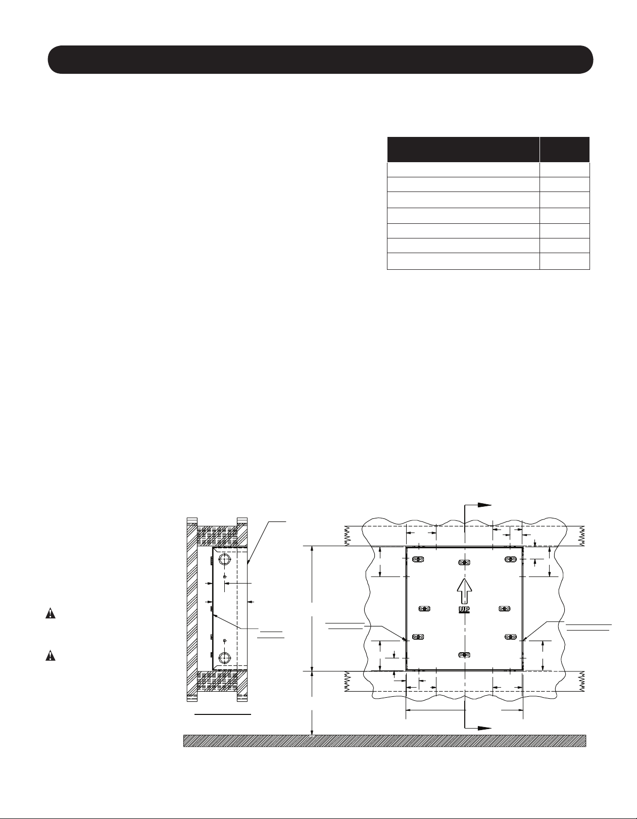
A
Installation
IMPORTANT: Consult local and general regulations before performing dryer installation. Make certain that the electrical
network is not overloaded. Do not connect to a branch circuit with a circuit breaker or fuse rated over 20 Amps. This is a UL
recommendation and complies with NEC #210-20.
A) DISCONNECT THE POWER SOURCE.
B) Fit and Finish Precautions;
1) Mount the hand dryer wall box at the recommended height per Table #1.
2) Mount the wall box ush - to a maximum of 1/8” (3.2mm) below the
nished wall surface for a proper recessed t.
3) Caulking is recommended AFTER installation of the aluminum base
assembly for a nished look and to help keep water out of the appliance.
(Caulking before installation may create a t problem.)
C) Mounting the Steel Wall Box;
CAUTION: Proper installation requires that the base be installed into the
steel wall box supplied.
1) Locate the steel wall box in the wall at the desired position, having the lower
edge of the box at the selected height specied in Table #1.
2) When two or more dryers are installed, they should be spaced 24” (61cm) minimum from center to center.
3) To mount the wall box, frame the opening in the wall per Figure #1.
4) Allow an opening in the framing to correspond with the preferred wall box knock-out for easy access of electrical conduit.
5) Mount the wall box in the opening. Fasten with No.10 (M5) wood screws or appropriate fasteners as required.
6) Using the nearest suitable distribution panel, run conduit.
7) To limit voltage drop for efcient operation, use No. 12 wire or larger as required by local electrical code or NEC.
8) Automatic hand dryers require dedicated 20 amp circuits to avoid unattended starting due to voltage uctuations. This includes
avoiding switched lighting circuits or other circuits where equipment may be switched on / off.
9) Provide a minimum length of 24” (61cm) of wire in the wall box to allow easy connection to the dryer terminals.
Table 1
Recommended Mounting Heights
from Floor to Dryer Bottom Edge
Men’s washrooms 42 (107)
Women’s washrooms 40 (102)
Children’s washrooms, ages 4-7 28 (71)
Children’s washrooms, ages 7-10 32 (81)
Children’s washrooms, ages 10-13 36 (91)
Children’s washrooms, ages 13-17 40 (102)
Handicap Mounting Height 34 (86)
in. (cm.)
D) Mounting the Dryer in the Wall Box;
1) Remove all shipping / packing material including the protective rubber corner squares if present on the dryer cover.
2) Use the security allen wrench supplied, to remove the (2) cover mounting screws. Remove the cover from the dryer base
assembly.
CAUTION: should be exercised when handling porcelain enameled cast iron covers. Do not drop or hit against hard
surfaces to avoid damaging the porcelain enamel.
3) Insert the base assembly in the pre-mounted wall box.
4) Facing the dryer, the blower housing will be on the left side as installed.
5) Fasten the base to the wall box with (4) 1/4-20 screws supplied.
Figure 1
6) Route the wires through
the openings in the base
assembly.
7) Connect eld wires to the
terminal block identied as
(L / N, L1 / L2).
8) Securely connect a
conrmed ground wire to the
1 1/4"
EDGE FLUSH
TO RECESS
1/8" MAX.
3"
3"
3"
1 1/4"
ground screw point.
DANGER: This hand dryer
must be properly earth
connected (grounded).
CAUTION: Route eld wires
away from any moving
parts or sharp edges.
9) Install the Hand Dryer
Cover with the (2) mounting
screws. To avoid chipping
the porcelain enamel, do not
3 1/2"
SECTION "A"
#16 GA.
STEEL BOX
12 1/2"
OPENING
8 KNOCKOUTS
DIMENSION "A"
SEE TABLE
7/8" + 1 1/8"
3"
1 1/4"
1 1/4"
3"
11 3/4"
OPENING
3"
A
over-tighten.
INSTALLATION MUST BE PERFORMED BY QUALIFIED ELECTRICAL PERSONNEL.
1 1/4"
3"
3"
8 HOLES FOR #10
WOOD SCREWS
3
Page 4

Parts List
Figure 2 - Repair Parts List For Hand Dryers
For Repair Parts, visit
www.WorldDryer.com.
Please provide following
information:
Model number
Serial number
Part description and
number shown in parts list
23
20
13
15
12
16
22
10
14
9
11
5
18
3
21
4
19
17
2
6
7
8
1
4
Page 5

Description Part Number Qty.
#
1 Wall Box (All) 17-034 1
2 Terminal Block (All) 156-3 1
3 Motor (D)XRA5, RA5 210K 1
3 Motor (D)XRA54, RA54, (D)XRA548, RA548, (D)XRA57, RA57 210AK 1
4 Motor Brush 206NL 2
5 Motor Mounting Strap 110-4A 2 sets
6 Motor Mounting Brackets 110-4 2
7 Micro Switch Only RA (All) 143F 1
8 Switch Timer Unit RA5 225 1
8 Switch Timer Unit RA54 225A 1
8 Switch Timer Unit RA548 225M 1
8 Switch Timer Unit RA57 225A7 1
9 Cover Complete, Cast Iron, Automatic, White XRA (All)* 703XA 1
9 Cover Complete, Cast Iron, Push-button, White RA (All)* 703A 1
9 Cover Complete, Stainless Steel , Automatic, Brushed DXRA (All)* 713DXA 1
10 Push-button Adapter, Gasket and Bushing Unit RA (All) 190K 1
11 Push-button Retaining Ring, Insulated Push Rod Tip, and Spring Kit RA (All) 193K 1
12 Security Allen Wrench, Cast Iron Cover 204TP 1
12 Security Allen Wrench, Steel Covers 56-006565 1
13 Inlet Grill, Cast Iron, Push-button, with Mtg. Hardware RA(All) 194-3K 1
r13 Inlet Grill, Cast Iron, Automatic, with Mtg. Hardware XRA(All) 194-3XRAK 1
14 Tamper Proof Cover Screw, Cast Iron Covers XRA, RA (All) 100B3 1
14 Tamper Proof Cover Screw, Steel Covers DXRA (All) 46-005023 1
15 Nozzle Assembly Kit 34-173K 1
16 Push-button Assembly Kit (Knob, Rod, Ring, Spring and Tip) RA (All) 185K 1
17 Thermostat Only 3/4” 1111-03 1
18 Blower Scroll Half with Base Mount and Thermostat 211PA 1
19 Fan Metal 101i 1
20 Blower Scroll Half - Left Side 112P 1
21 Heating Element (D)XRA5, RA5 213 1
21 Heating Element (D)XRA54, RA54, (D)XRA548, RA548 213A4 1
21 Heating Element (D)XRA57, RA57 213A7 1
22 Nameplate, Push-button RA (All) * 38-223 1
22 Nameplate, Automatic (D)XRA (All) * 38-224 1
23 Grid, Ground Assy (All) 12-001 1
r
Automatic Sensor Control - 115V, (D)XRA5 16-230-120 RAK 1
r
Automatic Sensor Control - 208-230V, (D)XRA54 16-240-208 RAK 1
r
Automatic Sensor Control - 220-240V, 50 Hz CE Only (D)XRA548 16-230-240 CEK 1
r
Automatic Sensor Control - 277V, (D)XRA57 16-240-277RAK 1
r
Fuse, Holder Assy, 277 V (D)XRA57, RA57 100F4A 1
r
Fuse, 1 Amp #FNQ-1, 277V (D)XRA57, RA57 100E3 1
* Specify model when ordering.
r Not shown.
5
Page 6

Maintenance
NOTE: Disconnect The Power Before Performing Any Of The Following
CLEANING INSTRUCTIONS:
Read complete Instructions before proceeding. Under normal use, cleaning the Dryer once a year will keep it in good operating
condition. If the washroom trafc is heavier than normal, the cleaning should be done every 6 months. Lint and dust build up inside the
dryer can result in damage to motor and heating element as well as hot emissions that could injure the user.
1. Remove two cover mounting screws from dryer cover using security Allen wrench provided. Support cover while removing screws.
2. Remove three (3) side screws holding blower housing together. Note position of heating element and protective screen. The lead
wires are directed through the clearance hole in the blower housing halves. Carefully remove the heating element however, do not
disconnect the wires.
3. Clean blower wheel halves using a 1/2“ diameter radial bristle brush. Insert brush through space between individual blades and
dislodge dirt. Do not bend or damage blades.
4. Vacuum out dirt from blower and housing, reposition heating element, protective screen and housing half and replace three (3) side
screws. Tighten gently making sure that mica heating element pieces are positioned in housing slots with connecting wires passing
through blower housing hole.
5. Use soft-medium bristle 1/2“ paint brush to clean dust and dirt from motor and switch timer. Do not bend switch blade when
cleaning.
6. Use a stiff brush to clean dirt from inside of nozzle grill and inlet grill. Water may be necessary to ush dirt from inlet grill. Dry inside
of cover before replacing if water is used.
7. Inspect motor brushes. To inspect brushes insert tooth pick in hole in end of brush assembly. If tooth pick is inserted more than one
inch, replace brushes. (See replacement instructions.)
8. Replace cover. Place cover squarely over base and push ush to wall. Insert 2 cover mounting screws and tighten until snug. Do
not over-tighten.
REPLACEMENT OF MOTOR BRUSHES
1. Remove locking spring clip securing brush holder.
2. Draw brush cap out of motor slowly until wire connector appears.
3. Detach wire connector and remove brush and holder assembly.
NOTE: When unpacking brush assembly from carton it is important to hold carbon brush in brush holder securely. P/N
206NL
4. Insert new assembly to point where wire quick connect connection can be made.
5. Push brush quick-connects on motor and brush sleeve together.
6. Push brush assembly back in place and insert locking spring clip.
REPLACEMENT OF HEATING ELEMENT
1. Remove three screws holding blower housing (#211P and #112P) together, and remove #112P side of housing.
2. Disconnect the white wires of the heating element at the terminal block and switch terminal. Replace with the new heating element
of proper voltage and wattage, being careful to connect it identically to the old one.
3. Hold element in position on stationary side of blower housing and slip removable side in place, making sure element frames t into
grooves in blower housing and both wires run through notch at top of air outlet. Reinstall the protective screen and replace three
screws fastening blower housing together.
4. Reconnect wires to terminal block and switch. Make certain all wires are properly reconnected and match the wiring diagram.
REPLACEMENT OF SWITCH TIMER MODELS RA
1. Remove screws from each of the two terminals on switch timer, marking wires for correct reconnection to switch terminals.
2. Replace defective timer with new one. (Specify Dryer Model when ordering Timer.)
3. Reconnect wires to terminals.
4. Replace cover (be sure cover ts squarely over base unit) and push in until cover is ush with wall and insert two cover mounting
screws. Do not over-tighten the mounting screws.
5. Turn on power to dryer.
6
Page 7
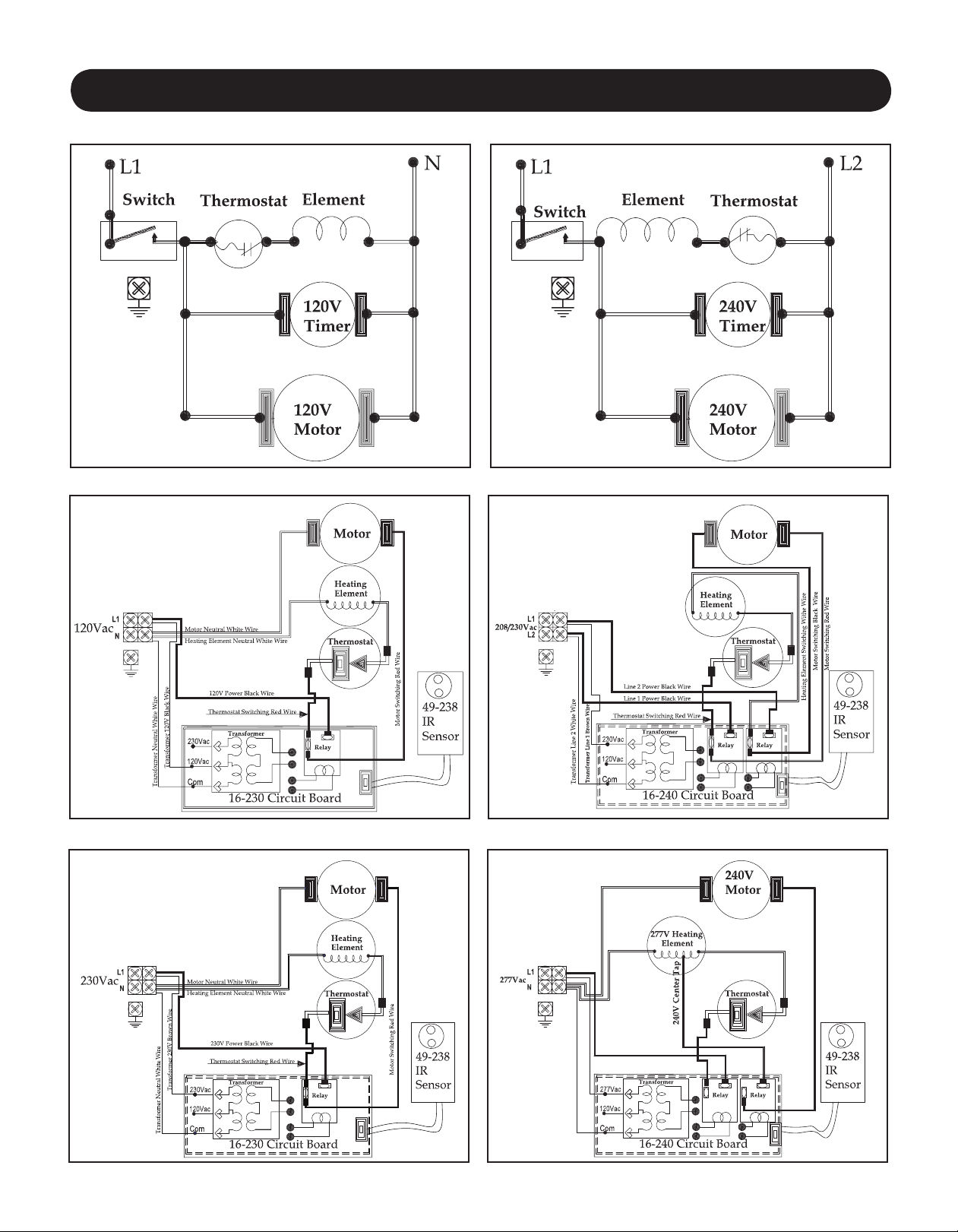
Wiring Diagram
Wiring Diagram - Model RA5
Wiring Diagram - Model (D) XRA5
Wiring Diagram - Model RA54/RA548
Wiring Diagram - Model (D) XRA54
Wiring Diagram - Model (D) XRA548 Wiring Diagram - Model (D) XRA57
7
Page 8

Troubleshooting Chart
Symptom Model Possible Cause(s) Corrective Action
Dryer fails to start XRA Sensor obstruction 1. Check Sensor Lens for foreign material or dirt. Clean Lens with soft damp cloth
All No power to the unit Check if power is “ON”
XRA Faulty Circuit Board (PCB)
XRA Faulty Motor If Relay “Click” is heard, heating element glows for 1-2 seconds, but unit does not
RA Faulty Timer / Switch
Dryer runs for approx.
100 seconds, then will
not re-start
Dryer runs continuous
and will not shut-off.
Dryer “Ghosts”
starts with no hands
present.
Dryer blows cold air. All Defective Heating Element
Dryer air too hot. All Machine is dirty 1. Inspect for foreign material. Using a soft brush and vacuum, clean fan and motor.
Dryer noisy or vibrates. All Fan not centered in housing
XRA Sensor obstruction 1. Check Sensor Lens for foreign material or dirt. Clean Lens with soft damp cloth
RA Faulty Timer With Dryer Cover Removed, depress the Timer Switch Blade;
XRA Sensor receiving false
and Sensor
Faulty Motor
signal or reection
Or
Fluctuating power supply
Or Defective Thermostat
■ Foreign object in Fan.
■ Broken or bent Fan.
■ Bent Motor shaft.
Trouble shooting should only be conducted by a qualied electrician.
and mild cleaning agent.
2. If Lens is damaged or scratched, replace it.
Check electrical connections.
Place hands under Sensor. Listen for PCB .
Relay “Click.” If no “Click” is heard, replace the PCB and Sensor.
start, replace the Motor.
With Dryer Cover Removed, depress the Timer Switch Blade;
a. Timer Motor should turn.
b. With an Ohm Meter, check for continuity across the Switch Terminals.
“No” in either test, replace Timer Assembly;
“Yes” in both tests, replace Motor.
and mild cleaning agent.
2. If Lens is damaged or scratched, replace the sensor.
Timer Motor should turn. “No” replace Timer Assembly.
1. Hand Dryer should be mounted a minimum of 18” above a reective surface.
2. Check if other Infrared operated appliance in the vacinity may be triggering the Dryer.
3. Multiple Hand Dryers on one circuit or Dryers sharing a lighting circuit. Automatic
Hand Dryers must be on dedicated circuits.
4. Building wiring may be insufcient gauge or too long of a run from the supply.
5. Replace the PCB and Sensor.
1. Check for break in Element Wire.
2. Check Heating Element and Thermostat for continuity. If open, replace as necessary.
2. Replace motor if running slow or erratic.
1. Fan may be rubbing against edge of Fan Housing. To center Fan;
a. On plastic fan unit, carefully “tap” the Fan Hub with a screw driver & small hammer
to center it until the Fan turns freely.
b. On metal fans, loosen the set screw and adjust the fan until it turns freely.
1. Inspect for foreign material. Using a soft brush and vacuum, clean fan and motor.
1. Replace Fan.
1. Replace Motor.
Limited Warranty
WORLD DRYER LIMITED TEN – YEAR WARRANTY. World Warm Air Hand Dryer, Model covered in this manual, is warranted by World Dryer Corporation to
the original user against defects in workmanship or materials under normal use for 10 years after date of purchase. Any part which is determined to be defective in material
or workmanship and returned to an authorized service location, as World designates, shipping costs prepaid, will be, as the exclusive remedy, repaired or replaced at World’s
option. For limited warranty claim procedures, see PROMPT DISPOSITION below. This limited warranty gives purchasers specic rights from jurisdiction to jurisdiction.
LIMITATION OF LIABILITY. To the extent allowable under applicable law, World’s liability for consequential and incidental damages is expressly disclaimed. World’s
liability in all events is limited to and shall not exceed the purchase price paid.
WARRANTY DISCLAIMER. World has made a diligent effort to provide product information and illustrate the products in this literature accurately; however, such information and illustrations are for the sole purpose of identication, and do not express or imply a warranty that the products are MERCHANTABLE, or FIT FOR A PARTICULAR
PURPOSE, or that the products will necessary conform to the illustrations or descriptions. Except as provided below, no warranty or afrmation on fact, expressed or implied,
other than as stated in the “LIMITED WARRANTY” above is made or authorized by World.
PRODUCT SUITABILITY. Many jurisdictions have codes and regulations governing sales, construction, installation, and/or use of products for certain purposes, which
may vary from those in neighboring areas. While World attempts to assure that the products comply with such codes, it cannot guarantee compliance, and cannot be responsible for how the product is installed or used. Before purchase and use of a product, review the product application, and all applicable national and local codes and regulations,
and be sure that the product, installation, and use will comply with them.
Certain aspects of disclaimers are not applicable to consumer products; e.g., (a) some jurisdictions do not allow the exclusion or limitation of incidental or consequential damages, so the above limitation or exclusion may not apply to you; (b) also, some jurisdictions do not allow a limitation on how long an implied warranty lasts, consequentially
the above limitation may not apply to you; and (c) by law, during the period of this Limited Warranty, and implied warranties of implied merchantability or tness for particular
purpose applicable to consumer products purchased by consumers, may not be excluded or otherwise disclaimed.
Manufactured by World Dryer Corporation, Berkeley, Illinois 60163 U.S.A.
PROMPT DISPOSITION. World will make a good faith effort for prompt correction or other adjustment with respect to any product which proves to be defective within
limited warranty. For any product believed to be defective within limited warranty, rst write or call dealer from whom the product was purchased. Dealer will give additional
directions. If unable to resolve satisfactorily, write to World, giving dealer’s name, address, date, and number of dealer’s invoice, and describing the nature of defect. Title and
risk of loss pass to buyer on delivery to common carrier. If product was damaged in transit to you, le claim with carrier.
8
68-836 Rev02
Page 9

Model A Recessed
ADA Compliant Heavy Duty Hand Dryer
Secamanos Empotrado Resistente Modelo A Compatible con ADA
Sèche-mains robuste à montage encastré, modèle A, conforme ADA
All XRA, RA Series
Todos los Modelos de las Series XRA y RA
Toutes les modèles de série XRA et RA
Please read and save these instructions. Read carefully before attempting to assemble, install, operate or service
the product described. Protect yourself and others by observing all safety information. Failure to comply with
instructions could result in personal injury and/or property damage. Retain instructions for future reference.
Por favor lea y guarde estas instrucciones. Léalas cuidadosamente antes de tratar de montar, instalar, operar o dar mantenimiento al producto aquí
descrito. Protéjase usted mismo y a los demás observando toda la información de seguridad. No seguir las instrucciones puede ocasionar daños,
tanto personales como materiales. Guarde estas instrucciones para referencia en el futuro.
Lire et conserver ces instructions. Les lire attentivement avant de commencer à assembler, installer, faire fonctionner, réparer ou entretenir l’appareil
décrit. Pour se protéger et protéger autrui, observer toutes les consignes de sécurité. Le fait de négliger d’appliquer ces instructions peut entraîner
des blessures et/ou des dommages matériels. Conserver ces instructions pour consultation ultérieure.
World Dryer Corporation
5700 McDermott Drive
Berkeley, IL 60163 U.S.A.
800-323-0701
1
www.worlddryer.com
Page 10

Descripción
El secamanos por aire caliente de World Dryer, empotrado y compatible con ADA, es accionado por un motor universal de alta velocidad
y suministra 2300 vatios de potencia de secado. Este secamanos funciona con un suministro eléctrico de 115 voltios de CA, 208/220-240
voltios de CA o 277 voltios de CA, dependiendo del modelo. Este grupo de productos incluye modelos automáticos y de activación por botón
pulsador. Este aparato ha sido diseñado para uso como un secador de manos, lo cual contribuye a una limpieza, higiénica y costo-efectiva de
las manos. Este secamanos se puede usar en entornos comerciales, industriales, de ocinas e instalaciones públicas.
Especicaciones Generales
Modelos
básicos
DXRA
XRA
RA
(*) Opción giratoria de la boquilla
Boquilla Tiempo de secado Dimensiones (A x P x Al) Peso Material de la cubierta
Fija Automático 333 mm x 351 mm x 102 mm 13,1 x 13,8 x 4 pulg. 12 kg / 26,5 lb. Acero inoxidable
Fija Automático 333 mm x 351 mm x 102 mm 13,1 x 13,8 x 4 pulg. 15,9 kg / 35 lb. Hierro fundido
Fija* 30 segundos 333 mm x 351 mm x 102 mm 13,1 x 13,8 x 4 pulg. 15,9 kg / 35 lb. Hierro fundido
Especicaciones del Sistema Eléctrico
Modelos Tipo Entrada eléctrica Amperaje Vatios
(D) XRA5
RA5
(D) XRA54
RA54
(D) XRA548
RA548
(Clasicación cULus, E19860, CE TUV-GS)
Automático 115 VCA, 60 Hz 20 2300
Botón pulsador 115 VCA, 60 Hz 20 2300
Automático 208-230 VCA, 60 Hz 10 2300
Botón pulsador 208-230 VCA, 60 Hz 10 2300
Automático 220-240 VCA, 50 Hz 10 2300
Botón pulsador 220-240 VCA, 50 Hz 10 2300
Información de Seguridad General
No desconectar la fuente de alimentación eléctrica antes de realizar la instalación o el
PELIGRO
• Siempre desconecte la fuente de alimentación antes de instalar el secamanos o darle mantenimiento.
PELIGRO
• Para utilizar este secamanos sin peligro, debe conectarse a tierra correctamente. En la base mural del secamanos se identica un punto
de conexión a tierra.
• Recomendamos utilizar un protector GFCI (interruptor de circuito de fallo a tierra) en emplazamientos mojados o húmedos, o donde lo exija
el código local.
ADVERTENCIA
• Utilice únicamente la energía eléctrica (voltaje y frecuencia) especicada para el modelo de secamanos que se esté instalando.
• Conecte el secamanos en el panel de distribución adecuado más cercano.
• Para limitar las caídas de voltaje, y garantizar un funcionamiento eciente, utilice el tamaño adecuado de conductor de acuerdo con los
requisitos de su localidad o del código eléctrico nacional.
• No conecte la unidad en un circuito ramal con protección de un cortacircuito o fusible de más de 20 amperios. Esto es de acuerdo con la
norma #210-20 del Código Eléctrico Nacional.
• Todos los modelos automáticos de secamanos deben tener un circuito dedicado de 20 amperios para satisfacer los requisitos de
Underwriters Laboratories, Inc. (UL).
• Encamine todo el cableado realizado durante la instalación lejos de todas las partes móviles dentro del secamanos.
ATENCIÓN
mantenimiento puede resultar en lesiones graves o la muerte debido a un choque eléctrico.
No conectar correctamente a tierra esta unidad puede resultar en un choque eléctrico grave
y/o la muerte.
Los siguientes: riesgo de incendio, lesiones personales o daño a la propiedad son
posibles si no se cumple con los códigos locales, el código eléctrico nacional
(NEC) estadounidense o las recomendaciones de seguridad.
El montaje incorrecto puede ocasionar lesiones personales o daños materiales.
Desembalaje
1. Retire todos los materiales de embalaje. Se recomienda reciclar los materiales.
2. Extraiga cuidadosamente el secamanos de la caja de envío, sin dejar caer el aparato.
3. Inspeccione el producto cuidadosamente para vericar si se han producido daños durante el transporte. Revise para vericar si hay partes
sueltas, que faltan o que están dañadas. Si el secamanos está dañado, infórmele prontamente sobre dicho daño al consignador o al
concesionario de quien compró el secamanos.
2
Page 11

Instalación
IMPORTANTE: Consulte los reglamentos locales y generales antes de realizar la instalación del secador. Verique que la red eléctrica
no esté sobrecargada. No conecte la unidad a un circuito derivado cuyo cortacircuito o fusible sobrepase los 20 amperios. Ésta es
una recomendación de UL y cumple con la norma n.º 210-20 del NEC.
A) DESCONECTE LA FUENTE DE ALIMENTACIÓN.
B) Precauciones de Montaje y Acabado:
1) Monte la caja de embutir del secamanos a la altura que se recomienda en la
Tabla n.º 1.
2) Monte la caja a ras de la cavidad, no más de 3,2 mm por detrás de la supercie
acabada de la pared, para que quede correctamente empotrada.
3) Se recomienda calafatear DESPUÉS de instalar el conjunto de la base de aluminio,
para dar un aspecto acabado y evitar que le entre agua al aparato (si se calafatea
antes de instalar, puede entorpecerse el montaje).
C) Montaje de la Caja de Embutir de Acero:
ATENCIÓN: Para que el aparato quede instalado correctamente, es necesario
instalar la base en la caja de embutir de acero que se proporciona.
1) Sitúe la caja de embutir de acero en el lugar de la pared que interese, de manera
que el borde inferior quede a la altura que se especica en la Tabla n.º 1.
2) Si se instalan más de un secador, deben separarse al menos 61 cm de centro a centro.
3) Para montar la caja de embutir, encuadre la abertura en la pared de acuerdo con la Figura n.º 1.
4) Haga que una abertura del encuadre corresponda con el agujero ciego de la caja de embutir que usted preera, para facilitar el acceso
del conducto portacables.
5) Monte la caja de embutir en la abertura. Fije con tornillos para madera n.º 10 (M5) o con los aanzadores que corresponda, según sea necesario.
6) Valiéndose del tablero de distribución correspondiente más próximo, pase el conducto portacables.
7) Según lo exija el código eléctrico regional o el NEC, utilice un conductor de calibre n.º 12 o mayor para limitar la caída de voltaje y
garantizar un funcionamiento eciente.
8) Para evitar que se enciendan accidentalmente como consecuencia de uctuaciones del voltaje, los secamanos automáticos deben
instalarse en circuitos dedicados de 20 A, es decir, no deben utilizarse circuitos conmutados de luces ni ningún otro circuito al que estén
conectados artefactos con interruptor.
9) El conductor debe tener al menos 61 cm de longitud en la caja de embutir para facilitar la conexión de los terminales del secamanos.
Tabla 1
Alturas de montaje recomendadas
desde el suelo hasta la parte
inferior del secamanos
Baños de hombres 107 (42)
Baños de mujeres 102 (40)
Baños de niños, 4 a 7 años de edad 71 (28)
Baños de niños, 7 a 10 años de edad 81 (32)
Baños de niños, 10 a 13 años de edad 91 (36)
Baños de niños, 13 a 17 años de edad 102 (40)
Altura de montaje para discapacitados 86 (34)
cm
(pulg)
D) Montaje del secamanos en la caja de embutir:
1) Elimine todo el embalaje, incluidos los protectores de caucho de las esquinas de la cubierta del secamanos, si los trajera.
2) Utilice la llave Allen de seguridad suministrada para extraer los (2) tornillos de montaje de la cubierta. Retire la cubierta del conjunto de la
base del secamanos.
ATENCIÓN: Las cubiertas de fundición con esmalte de porcelana deben manipularse con cuidado. No se deben dejar caer
ni golpear contra supercies duras, para evitar dañar el esmalte de porcelana.
3) Introduzca el conjunto de base en la caja de embutir que se ha montado previamente.
4) Frente al secamanos, la carcasa del soplador debe quedar instalada en el costado izquierdo.
5) Fije la base a la caja de embutir con los cuatro (4) tornillos 1/4-20 que se proporcionan.
6) Pase los conductores por las
aberturas del conjunto de la base.
7) Conecte el cableado de campo al
bloque de terminales identicado
como (L / N, L1 / L2).
8) Conecte rmemente un cable
de tierra conrmado al tornillo
de conexión a tierra.
PELIGRO: Este secamanos
debe conectarse a tierra
(ponerse a tierra) correctamente.
ATENCIÓN: Dirija el cableado
de campo de manera de evitar
todas las piezas móviles y
los bordes cortantes.
9) Instale la cubierta del secamanos
con los dos (2) tornillos de
montaje. Para evitar que se
pique el esmalte de porcelana,
no apriete demasiado.
8,9 c m
SECCIÓN “A”
BORDE A RAS
DE LA CAVIDAD
3,2 mm MÁX.
3,2 c m
CAJA DE ACERO
CALIBRE 16
ABERT URA
DE 31 ,75 cm
8 AGUJEROS
DIMENSIÓN “A”
VER TABLA
CIEGOS
7/8 pulg. +
1 1/8 pulg.
Figura 1
7,6 c m
7,6 c m
3,2 c m
3,2 c m
7,6 c m
7,6 c m
A
ABERT URA
DE 29 ,85 cm
A
7,6 c m
7,6 c m
3,2 c m
3,2 c m
7,6 c m
7,6 c m
8 AGUJEROS PAR A
TORNILLOS PARA
MADERA n.º 10
LA INSTALACIÓN DEBE SER REALIZADA POR PERSONAL ELÉCTRICO CALIFICADO.
3
Page 12

Lista de Piezas
Figura 2 – Lista de Piezas para Secamanos
Para información sobre
repuestos, visite
www.WorldDryer.com
Por favor proporcione la
siguiente información:
Número de modelo
Número de serie
Descripción de la pieza
y número indicados
en la lista de partes
23
20
13
15
12
16
22
10
14
9
11
5
18
3
21
4
19
17
2
6
7
8
1
4
Page 13

Descripción Número de Parte Cant.
#
1 Caja de embutir (todos)
2 Bloque de terminales (todos)
3
Motor (D)XRA5, RA5 210K
3
Motor (D)XRA54, RA54, (D)XRA548, RA548, (D)XRA57, RA57 210AK
4 Escobilla de motor
5 Abrazadera de montaje del motor
6 Soportes de montaje del motor
7 Microinterruptor solamente RA (todos)
8 Unidad de temporización del interruptor RA5
8 Unidad de temporización del interruptor RA54
8 Unidad de temporización del interruptor RA548
8 Unidad de temporización del interruptor RA57
9 Cubierta completa, fundición, funcionamiento automático, color blanco XRA (todos)*
9 Cubierta completa, fundición, de pulsador, color blanco RA (todos)*
9 Cubierta completa, acero inoxidable, funcionamiento automático, acabado cepillado DXRA (todos)*
10 Unidad de adaptador de pulsador, empaquetadura y buje RA (todos)
11 Juego de anillo de retención, punta de varilla de empuje aislada y resorte para pulsador RA (todos)
12 Llave Allen de seguridad, cubierta de fundición
12 Llave Allen de seguridad, cubiertas de acero
13 Rejilla de entrada, fundición, de pulsador, con tornillería de montaje RA (todos)
Rejilla de entrada, fundición, funcionamiento automático, con tornillería de montaje XRA (todos)
r13
14 Tornillo resistente a manipulaciones para la cubierta, cubiertas de fundición XRA, RA (todos)
14 Tornillo resistente a manipulaciones para la cubierta, cubiertas de fundición DXRA (todos)
15 Juego del conjunto de la boquilla
16 Juego del conjunto del pulsador (perilla, varilla, anillo, resorte y punta) RA (todos)
17 Termostato solamente 19 mm (3/4 pulg)
18 Mitad de la voluta del soplador con montaje en la base y termostato
19 Pieza de metal del ventilador
20 Mitad de la voluta del soplador, lado izquierdo
21 Elemento calentador (D)XRA5, RA5
21 Elemento calentador (D)XRA54, RA54, (D)XRA548, RA548
17-034
156-3
206NL
110-4A
110-4
143F
225
225A
225M
225A7
703XA5-974AK
703A5-974AK
713DXA5-Q973AK
190K
193K
204TP
56-006565
194-3K
194-3XRAK
100B3
46-005023
34-173K
185K
1111-03
211PA
101i
112P
213
213A4
1
1
1
1
2
2 juegos
2
1
1
1
1
1
1
1
1
1
1
1
1
1
1
1
1
1
1
1
1
1
1
1
21 Elemento calentador (D)XRA57, RA57
22 Placa de identicación, de pulsador RA (todos)*
22 Placa de identicación, funcionamiento automático XRA (todos)*
23 Rejilla, Montaje de tierra (todos)
Control de sensor automático, 115V, (D)XRA5
r
Control de sensor automático, 208-230 V, (D)XRA54
r
Control de sensor automático, 220-240 V, 50 Hz CE solamente (D)XRA548
r
Control de sensor automático, 277 V, (D)XRA57
r
Montaje del sostenedor del fusible, 277 V, (D)XRA57, RA57
r
Fusible, 1 Amp, #FNQ-1, 277 V, (D)XRA57, RA57
r
* Especique el modelo en su pedido. r No se muestra.
5
213A7
38-223
38-224
12-001
16-230-120 RAK
16-240-208 RAK
16-230-240 CEK
16-240-277RAK
100F4A
100E3
1
1
1
1
1
1
1
1
1
Page 14

Mantenimiento
AVISO: Desconecte la alimentación eléctrica antes de efectuar cualquier de estos procedimientos
INSTRUCCIONES DE LIMPIEZA:
Lea todas las instrucciones antes de proceder. Bajo uso normal, la limpieza del Secador una vez al año lo mantendrá en buena condición
de funcionamiento. Si el tráco en el baño es más pesado que lo normal, la limpieza debe realizarse cada 6 meses. Las acumulaciones de
pelusas y polvo dentro del secador pueden dañar el motor y el elemento calentador, y también pueden producir emisiones calientes que
podrían lesionar a los usuarios.
1. Extraiga dos tornillos de montaje de la cubierta del secador usando la llave Allen de seguridad suministrada. Sujete la cubierta mientras
extrae los tornillos.
2. Extraiga tres (3) tornillos laterales que sujetan la carcasa del soplador. Observe la posición del elemento calentador y de la pantalla
protectora. Los conductores principales atraviesan el agujero pasante en las mitades de la carcasa del soplador. Retire cuidadosamente
el elemento calentador, pero sin desconectar los conductores.
3. Limpie las mitades de la rueda del soplador usando un cepillo cilíndrico de cerdas radiales de 12,7 mm (1/2 pulg.) de diámetro. Inserte
el cepillo en los espacios entre las paletas individuales y desaloje la suciedad. No doble ni dañe las aspas.
4. Aspire la suciedad del secador y de la carcasa, vuelva a colocar el elemento calentador, la pantalla protectora y la mitad de la carcasa,
y reinstale los tres (3) tornillos laterales. Apriete ligeramente y asegúrese que las piezas del elemento calentador de mica estén situadas
en las ranuras de la carcasa y los conductores de conexión pasen a través del agujero en la carcasa del soplador.
5. Use una brocha para pintar de cerdas medio-suave de 12,7 mm (1/2 pulg.) para limpiar el polvo y la suciedad del motor y del temporizador
interruptor. No doble las paletas del interruptor cuando limpie el mismo.
6. Utilice un cepillo de cerdas rmes para limpiar la suciedad del interior de la rejilla de la boquilla y de la rejilla de entrada. Quizá se necesite
agua para purgar la suciedad de la rejilla de entrada. Si se utiliza agua, seque el interior de la cubierta antes de volverla a montar.
7. Inspeccione las escobillas del motor. Para inspeccionar las escobillas, inserte un palillo de dientes en el agujero en el extremo del
conjunto de las escobillas. Si puede insertar el palillo de dientes más de 2,5 cm, reemplace las escobillas. (Consulte las instrucciones
de reemplazo).
8. Vuelva a instalar la cubierta. Coloque la cubierta encuadrada sobre la base y presiónela hasta que esté al ras contra la pared. Inserte
dos (2) tornillos de montaje de la cubierta y apriételos hasta que estén ajustados. No los apriete demasiado.
REEMPLAZO DE LAS ESCOBILLAS DEL MOTOR
1. Retire la presilla de resorte de jación que sujeta el portaescobillas.
2. Saque lentamente la tapa de la escobilla fuera del motor hasta que aparezca el conector del conductor.
3. Desconecte el conector del conductor y retire el conjunto del portaescobilla y la escobilla.
AVISO: Cuando desembale el conjunto de las escobillas de la caja de envío, es importante mantener rmemente sujetada la
escobilla de carbón en el portaescobillas. P/N 206NL
4. Inserte el conjunto nuevo en el punto donde se pueda hacer la conexión rápida del conductor.
5. Conecte a presión los manguitos de las escobillas en los conectores rápidos para escobillas en el motor.
6. Vuelva a colocar el conjunto de las escobillas en su lugar e inserte la presilla de resorte de jación.
REEMPLAZO DEL ELEMENTO CALENTADOR
1. Extraiga los tres tornillos que unen las partes de la carcasa del soplador (n.
2. Desconecte los conductores blancos del elemento calentador en el bloque de terminales y de las terminales del interruptor. Instale
el nuevo elemento calentador con tensión y vataje correctos, observando la misma conexión que se utilizó con el elemento
calentador antiguo.
3. Inmovilice el elemento en el lado jo de la carcasa del soplador y deslice el lado desmontable a su lugar, vericando que las estructuras
del elemento encajen en las ranuras de la carcasa del soplador y que ambos conductores pasen a través de la muesca en la parte
superior de la salida de aire. Reinstale la pantalla protectora y los tres tornillos que unen las partes de la carcasa del soplador.
4. Vuelva a conectar los conductores al bloque de terminales y al interruptor. Verique que todos los conductores queden debidamente
reconectados, prestando atención al diagrama de cableado.
REEMPLAZO DEL TEMPORIZADOR DEL INTERRUPTOR (MODELOS RA)
1. Extraiga los tornillos de cada una de las dos terminales en el temporizador interruptor, y marque los conductores para poder volverlos
a conectar correctamente en las terminales del interruptor.
2. Reemplace el temporizador defectuoso con uno nuevo. (Especique el Modelo de Secador cuando pida el Temporizador).
3. Vuelva a conectar los conductores en las terminales.
4. Vuelva a instalar la cubierta (asegurándose que la cubierta encaje perfectamente sobre la unidad base) y presiónela hacia adentro hasta
que la cubierta esté al ras con la pared e inserte los dos tornillos de montaje de la cubierta. No apriete demasiado los tornillos de montaje.
5. Conecte la alimentación eléctrica para el secador.
os
211P y 112P), y retire el lado n.º 112P de la carcasa.
6
Page 15

Diagrama de Cableado
Diagrama de Cableado - Modelo RA5
Diagrama de Cableado - Modelo (D) XRA5
Diagrama de Cableado - Modelo RA54/RA548
Diagrama de Cableado - Modelo (D) XRA54
Diagrama de Cableado - Modelo (D) XRA548 Diagrama de Cableado - Modelo (D) XRA57
7
Page 16

Tabla de Identicación de Problemas
Síntoma Modelo Causa(s) Posible(s) Medida Correctiva
El secador no arranca.
El secador funciona aprox.
100 segundos y ya no
vuelve a encenderse.
El secamanos funciona de
forma continua y no se apaga.
El secamanos arranca
espontáneamente, sin que se
coloquen las manos debajo.
El aire que expulsa el
secamanos es frío.
El aire que expulsa el
secamanos es demasiado
caliente.
El secamanos produce
ruido o vibra.
XRA
Todos
XRA
XRA
RA
XRA
RA
XRA
Todos Elemento calentador o
Todos La máquina está sucia 1. Examine para vericar la presencia de materias extrañas. Con un cepillo suave y una
Todos Ventilador descentrado en
Sensor obstruido 1. Compruebe que la lente del sensor no esté sucia ni tenga materias extrañas. Limpie la
La unidad no recibe
alimentación eléctrica
Placa de circuitos impresos
y sensor averiados
Motor averiado Si la unidad no arranca, a pesar de producirse el chasquido del relé y encenderse el
Temporizador o interruptor
averiados
Motor averiado
Sensor obstruido 1. Compruebe que la lente del sensor no esté sucia ni tenga materias extrañas. Limpie la
Temporizador averiado Quite la cubierta del secamanos y oprima la paleta del interruptor con temporizador;
El sensor está recibiendo
una señal falsa o el reejo
de alguna supercie
O
La alimentación eléctrica
uctúa
termostato defectuosos
la carcasa
■ Presencia de objeto extraño
en el ventilador.
■ Ventilador roto o doblado.
■ Eje del motor doblado.
lente con un trapo suave y húmedo, y un producto de limpieza suave.
2. Si la lente está dañada o rayada, reemplácela.
Compruebe que la unidad esté encendida.
Revise las conexiones eléctricas.
Ponga las manos debajo del sensor. Preste atención al chasquido del relé de la placa de
circuitos impresos. Si no se escucha, reemplace la placa de circuitos impresos y el sensor.
elemento calentador 1 ó 2 segundos, reemplace el motor.
Quite la cubierta del secamanos y oprima la paleta del interruptor con temporizador;
a. El motor del temporizador debe arrancar.
b. Con un ohmímetro, verique la continuidad entre los terminales del interruptor.
Si la respuesta es negativa en alguna de las pruebas, reemplace el conjunto del temporizador;
Si la respuesta es armativa en ambas pruebas, reemplace el motor.
lente con un trapo suave y húmedo, y un producto de limpieza suave.
2. Si la lente está dañada o rayada, reemplace el sensor.
El motor del temporizador debe arrancar. Si la respuesta es negativa, reemplace
el conjunto del temporizador.
1. El secamanos debe montarse al menos 45,7 cm por encima de las supercies
reectantes.
2. Verique si hay algún otro artefacto accionado por infrarrojos cerca del secamanos que
pueda estar activándolo.
3. Hay varios secamanos en un mismo circuito, o los secamanos comparten un circuito de
luces. Los secamanos automáticos deben instalarse en circuitos dedicados.
4. El cableado de la edicación tiene un calibre insuciente o se extiende demasiado desde
la alimentación eléctrica.
5. Reemplace la placa de circuitos impresos y el sensor.
1. Verique si está roto el conductor del elemento.
2. Verique la continuidad en el elemento calentador y el termostato. Si no hay continuidad,
reemplace según sea necesario.
aspiradora, limpie el ventilador y el motor.
2. Reemplace el motor, si el funcionamiento es lento o irregular.
1. Es posible que el ventilador esté rozando con el borde de la carcasa del ventilador.
Para centrar el ventilador:
a. En ventiladores de plástico, golpee con cuidado el cubo del ventilador con un
destornillador y un martillo pequeño para centrarlo, hasta que el ventilador gire libremente.
b. En ventiladores de metal, aoje el tornillo prisionero y ajuste el ventilador hasta que gire
libremente.
1. Examine para vericar la presencia de materias extrañas. Con un cepillo suave y una
aspiradora, limpie el ventilador y el motor.
1. Reemplace el ventilador.
1. Reemplace el motor.
Sólo un electricista calicado debe diagnosticar y
solucionar posibles fallas.
Garantía Limitada
GARANTÍA LIMITADA DE DIEZ AÑOS DE WORLD DRYER. World Dryer Corporation le garantiza al usuario original que el modelo del secamanos de aire caliente World
Dryer tratado en este manual estará libre de defectos de fabricación y materiales si se somete a un uso normal por diez años a partir de la fecha de compra. Cualquier pieza que se halle
defectuosa, ya sea por materiales o construcción, y se devuelva a un centro de reparación autorizado, según lo indique World Dryer, con los costos de envío pagados por adelantado, se
reparará o reemplazará, como remedio exclusivo, a la discreción de World Dryer. Para información relacionada con los procedimientos de reclamación provistos por la garantía limitada,
consulte más adelante la sección ATENCIÓN OPORTUNA. Esta garantía limitada conere al comprador derechos especícos que varían de una jurisdicción a otra.
LÍMITES DE RESPONSABILIDAD. En la medida en que las leyes aplicables lo permitan, se excluye expresamente la responsabilidad de World Dryer por daños indirectos o
menores. La responsabilidad de World Dryer se limita al precio de compra pagado, al cual no sobrepasará.
EXCLUSIÓN DE RESPONSABILIDAD DE LA GARANTÍA. World Dryer se ha esforzado diligentemente en proporcionar a través de este manual información e
ilustraciones concernientes al producto; sin embargo, esta información y estas ilustraciones tienen como único n la identicación del producto, y no expresan ni implican garantía de que
los productos sean VENDIBLES o ADECUADOS A UN PROPÓSITO EN PARTICULAR, ni que se ajusten necesariamente a las ilustraciones o descripciones. Con excepción de lo que
se establece a continuación, World Dryer no hace ni autoriza ninguna garantía o armación de hecho, expresa o implícita, que no se estipule en la “GARANTÍA LIMITADA” anterior.
ADECUACIÓN DEL PRODUCTO. Muchas jurisdicciones tienen códigos o regulaciones sobre la venta, el diseño, la instalación y/o el uso de productos para ciertas aplicaciones;
dichas leyes pueden variar de un área a otra. Si bien World Dryer trata de que los productos cumplan con estos códigos, no puede garantizar su cumplimiento ni puede hacerse
responsable de la forma en que se instale o utilice el producto. Antes de comprar y utilizar el producto, revise su aplicación y todos los códigos y reglamentos nacionales y locales
aplicables, y asegúrese de que el producto, la instalación y el uso los cumplan.
Ciertos aspectos de las limitaciones de responsabilidad no se aplican a los productos de consumo; es decir (a) algunas jurisdicciones no permiten la exclusión o limitación de daños
menores o indirectos, por lo cual la limitación o exclusión anterior quizás no se aplique en su caso; (b) asimismo, algunas jurisdicciones no permiten limitar el plazo de las garantías
implícitas, por lo cual la limitación anterior quizás no se aplique en su caso; y (c) por ley, mientras estén vigentes, no pueden excluirse ni de ninguna otra manera denegarse la
Garantía Limitada y las garantías implícitas de comerciabilidad o idoneidad para un propósito en particular implícitas que corresponden a los productos de consumo adquiridos por los
consumidores. Fabricado por World Dryer Corporation, Berkeley, Illinois 60163 U.S.A.
ATENCIÓN OPORTUNA. World Dryer hará un esfuerzo de buena fe para corregir oportunamente o hacer otros ajustes relacionados con cualquier producto que resulte defectuoso
dentro de los términos de esta garantía limitada. En el caso de que encuentre un producto defectuoso y que esté cubierto dentro de los límites de esta garantía haga el favor de escribir
primero, o llame, al distribuidor a quien le compró el producto. El distribuidor le dará las instrucciones adicionales. Si no logra resolver el problema de forma satisfactoria, escriba a World
Dryer, y proporcione el nombre y la dirección del distribuidor, así como la fecha y el número de su factura, y describa la naturaleza del defecto. La propiedad del artículo y el riesgo de
pérdida pasan al comprador en el momento de la entrega del artículo a la compañía de transporte. Si el producto se daña durante el transporte, debe presentar su reclamo a la
compañía transportista.
8
68-836 Rev02
Page 17

Model A Recessed
ADA Compliant Heavy Duty Hand Dryer
Secamanos Empotrado Resistente Modelo A Compatible con ADA
Sèche-mains robuste à montage encastré, modèle A, conforme ADA
All XRA, RA Series
Todos los Modelos de las Series XRA y RA
Toutes les modèles de série XRA et RA
Please read and save these instructions. Read carefully before attempting to assemble, install, operate or service
the product described. Protect yourself and others by observing all safety information. Failure to comply with
instructions could result in personal injury and/or property damage. Retain instructions for future reference.
Por favor lea y guarde estas instrucciones. Léalas cuidadosamente antes de tratar de montar, instalar, operar o dar mantenimiento al producto aquí
descrito. Protéjase usted mismo y a los demás observando toda la información de seguridad. No seguir las instrucciones puede ocasionar daños,
tanto personales como materiales. Guarde estas instrucciones para referencia en el futuro.
Lire et conserver ces instructions. Les lire attentivement avant de commencer à assembler, installer, faire fonctionner, réparer ou entretenir l’appareil
décrit. Pour se protéger et protéger autrui, observer toutes les consignes de sécurité. Le fait de négliger d’appliquer ces instructions peut entraîner
des blessures et/ou des dommages matériels. Conserver ces instructions pour consultation ultérieure.
World Dryer Corporation
5700 McDermott Drive
Berkeley, IL 60163 U.S.A.
800-323-0701
www.worlddryer.com
1
Page 18

Description
Le sèche-mains à air chaud à moteur rapide universel, conforme ADA et à montage encastré de World Dryer offre une puissance de séchage
de 2 300 watts. Ce sèche-mains fonctionne sur une alimentation électrique alternative de 115 volts, 208/220-240 volts ou 277 volts, selon le
modèle. Des modèles automatiques et à bouton-poussoir sont représentés dans cette gamme. Cet appareil est conçu pour sécher les mains
de façon sanitaire d’une manière, hygiénique et économique. Ce sèche-mains est conçu pour être utilisé dans les magasins, usines, bureaux et
bâtiments publics.
Caractéristiques générales
Modèles de base Buse Cycle de séchage Dimensions (Lar. x P x H) Poids Matériau du carter
DXRA
XRA
RA
(*)Option buse rotative
Fixe Automatique 333 mm x 351 mm x 102 mm 13,1 po x 13,8 po x 4 po 12 kg / 26,5 lb Acier inoxydable
Fixe Automatique 333 mm x 351 mm x 102 mm 13,1 po x 13,8 po x 4 po 15,9 kg / 35 lb Fonte
Fixe* 30 secondes 333 mm x 351 mm x 102 mm 13,1 po x 13,8 po x 4 po 15,9 kg / 35 lb Fonte
Caractéristiques électriques
Modèles Type Consommation électrique Intensité Watts
(D) XRA5
RA5
(D) XRA54
RA54
(D) XRA548
RA548
(Homologation cULus, E19860, CE TUV-GS)
Automatique 115 V c.a., 60 Hz 20 2 300
Bouton-poussoir 115 V c.a., 60 Hz 20 2 300
Automatique 208-230 V c.a., 60 Hz 10 2 300
Bouton-poussoir 208-230 V c.a., 60 Hz 10 2 300
Automatique 220-240 V c.a., 50 Hz 10 2 300
Bouton-poussoir 220-240 V c.a., 50 Hz 10 2 300
Consignes générales de sécurité
Le fait de ne pas débrancher la source d’alimentation avant de procéder à l’installation, à la
DANGER
• Toujours débrancher la source d’alimentation avant de réparer, d’entretenir ou d’installer le sèche-mains.
DANGER
• Ce sèche-mains doit être mis à la terre correctement pour fonctionner en toute sécurité. Un point de raccordement à la terre est identié
sur la base de xation murale du sèche-mains.
• Nous recommandons une protection par disjoncteur de fuite à la terre dans les endroits mouillés ou humides, ou si les normes locales
l’exigent.
AVERTISSEMENT
• N’utiliser que le type d’alimentation électrique (en matière de tension et fréquence) spécié pour le modèle de sèche-mains en cours
d’installation.
• Raccorder le sèche-mains au tableau de distribution adapté le plus proche.
• Pour limiter les chutes de tension et garantir un fonctionnement efcace, utiliser du l correspondant au calibre exigé par le code local ou
le code national de l’électricité.
• Ne pas raccorder l’appareil à un circuit de dérivation protégé par un disjoncteur ou un fusible de plus de 20 ampères. Cette exigence est
stipulée par l’article 210-20 du code national de l’électricité.
• Pour se conformer à l’homologation Underwriters Laboratories, Inc. (UL), tous les modèles automatiques de sèche-mains doivent être
installés sur un circuit dédié de 20 ampères.
• Faire passer l’ensemble du câblage sur site à l’écart des pièces mobiles qui sont à l’intérieur du sèche-mains.
ATTENTION
réparation ou à l’entretien peut entraîner des blessures graves ou mortelles résultant d’un
choc électrique.
Veiller à mettre cet appareil à la terre correctement an d’éviter un risque de choc électrique
grave, voire mortel.
Un risque d’incendie, de blessures ou de dommages matériels est possible en
cas d’inobservation des codes locaux, du code national de l’électricité ou des
recommandations de sécurité.
Un montage incorrect peut provoquer des accidents corporels et des dommages
matériels.
Déballage
1. Enlever tous les produits d’emballage. Il est recommandé de les recycler.
2. Sortir le sèche-mains du carton avec précaution, en veillant à ne pas le faire tomber.
3. Vérier soigneusement qu’aucun dommage n’est survenu durant le transport. Examiner les pièces pour vérier si certaines sont desserrées,
manquantes ou endommagées. Si le sèche-mains est endommagé, informer immédiatement l’expéditeur ou le concessionnaire qui l’a vendu.
2
Page 19

Installation
IMPORTANT : Consulter les réglementations locale et générale avant d’installer le sèche-mains. S’assurer que le réseau électrique
n’est pas surchargé. Ne pas raccorder l’appareil à un circuit de dérivation protégé par un disjoncteur ou un fusible de plus de 20 A.
Il s’agit d’une recommandation UL conforme à l’article 210-20 du code national de l’électricité.
A) COUPER LA SOURCE D’ALIMENTATION.
B) Précautions pour l’adaptation et la nition
1) Monter la boîte d’applique du sèche-mains à la hauteur recommandée au Tableau n°1.
2) Monter la boîte d’applique sans saillie à un maximum de 3,2 mm en-dessous de la
surface nie du mur pour un bon encastrement.
3) Il est recommandé de calfeutrer APRÈS l’installation de la base en aluminium pour
parfaire la nition et pour aider à protéger l’appareil de l’eau. (Le calfeutrage avant
l’installation peut créer un problème d’adaptation.)
C) Monter la boîte d’applique en acier
ATTENTION : L’installation correcte nécessite l’installation de la base dans la
boîte d’applique en acier fournie.
1) Placer la boîte d’applique en acier sur le mur à la position souhaitée, en prenant soin de
placer le bord inférieur de la boîte à la hauteur sélectionnée indiquée au Tableau n°1.
2) Lorsqu’on installe plusieurs sèche-mains, on doit observer une distance minimale de
séparation entre eux de 61 cm de centre à centre.
3) Pour monter la boîte d’applique, cadrer l’ouverture dans le mur selon la Figure n°1.
4) Laisser une ouverture dans l’ossature correspondant au placement préféré du branchement électrique pour la boîte d’applique an d’avoir
un accès facile à la conduite électrique.
5) Monter la boîte d’applique dans l’ouverture. Fixer avec les vis à bois n°10 (M5) ou les xations appropriées, le cas échéant.
6) En utilisant le tableau de distribution adapté le plus proche, poser la conduite électrique.
7) Pour limiter les chutes de tension et garantir un fonctionnement efcace, utiliser du l de calibre 12 ou plus gros si le code local ou national
de l’électricité l’exige.
8) Les sèche-mains automatiques nécessitent des circuits dédiés de 20 A pour éviter un démarrage automatique en raison des uctuations
de tension. Il faut donc également éviter les circuits d’éclairage à interrupteurs ou d’autres circuits où les équipements peuvent être
allumés ou éteints.
9) Laisser dépasser une longueur de câble minimale de 61 cm de la boîte d’applique pour permettre un branchement facile aux bornes
du sèche-mains.
Tableau 1
Hauteurs de montage recommandées
entre le sol et le bord inférieur du
sèche-mains
Toilettes pour hommes 107 (42)
Toilettes pour femmes 102 (40)
Toilettes pour enfants de 4 à 7 71 (28)
Toilettes pour enfants de 7 à 10 ans 81 (32)
Toilettes pour enfants de 10 à 13 ans 91 (36)
Toilettes pour enfants de 13 à 17 ans 102 (40)
Hauteur de montage pour personnes
handicapées
cm (po)
86 (34)
D) Monter le sèche-mains dans la boîte d’applique
1) Éliminer tout matériel d’expédition ou d’emballage, notamment les coins de protection en caoutchouc si présents sur le capot du sèche-mains.
2) Utiliser la clé mâle à six pans de sécurité fournie pour enlever les deux (2) vis de montage du capot. Enlever le capot de la base du
sèche-mains.
ATTENTION : Faire bien attention lors de la manipulation de capots en fonte à porcelaine émaillée. Ne pas laisser tomber ni
cogner contre des surfaces dures an d’éviter d’endommager la porcelaine émaillée.
3) Insérer la base dans la boîte d’applique prémontée.
4) Lorsqu’en face du sèche-mains, le carter de la soufante doit se trouver à gauche lors de l’installation.
5) Visser la base sur la boîte
d’applique avec les 4 vis
1/4-20 fournies.
6) Faire passer les câbles par
les ouvertures de la base.
7) Brancher les câbles de la
conduite électrique au bornier
identié (L / N, L1 / L2).
BORD À NIVEAU AVEC
L’ENCASTREMENT
À 3,2 mm MAX.
Figure 1
7,6 c m
7,6 c m
A
7,6 c m
3,2 c m
3,2 c m
7,6 c m
8) Bien serrer un l de mise à la
terre vérié à la vis de la borne
de terre.
DANGER : Ce sèche-mains doit
être correctement mis à la terre.
ATTENTION : Acheminer les
ls de la conduite électrique
à l’écart de toute pièce mobile
ou bords coupants.
9) Installer le capot du sèche-mains
avec les (2) vis de montage. Pour
éviter d’écailler la porcelaine
8,9 c m
SECTION « A »
3,2 c m
BOÎTE EN ACIER
DE CALIBRE 16
OUVER TURE
DE 31 ,75 cm
8 ORIFICES
7/8 PO + 1 1/8 PO
DIMENSION « A »
VOIR TABLEAU
7,6 c m
3,2 c m
3,2 c m
7,6 c m
OUVER TURE
DE 29 ,85 cm
A
7,6 c m
7,6 c m
8 ORIFICES POU R
VIS À BOIS N°1 0
émaillée, ne pas trop serrer.
TOUTE INSTALLATION DOIT ÊTRE EFFECTUÉE PAR UN ÉLECTRICIEN AGRÉE.
3
Page 20

Liste des pièces
Figure 2 – Liste des pièces détachées des sèche-mains
Pour les pièces détachées,
consulter
www.WorldDryer.com
Fournir les renseignements
suivants :
Numéro de modèle
Numéro de série
Description et numéro
de la pièce gurant sur
la liste des pièces
23
20
13
15
12
16
22
10
14
9
11
5
18
3
21
4
19
17
2
6
7
8
1
4
Page 21

Description Numéro de pièce Qté.
#
1 Boîte d'applique (tous)
2 Bornier (tous)
3 Moteur (D)XRA5, RA5
3 Moteur ((D)XRA54, RA54, (D)XRA548, RA548, (D)XRA57, RA57
4 Balais du moteur
5 Bride de montage du moteur
6 Supports de montage du moteur
7 Microcommutateur seulement RA (tous)
8 Minuteur RA5
8 Minuteur RA54
8 Minuteur RA548
8 Minuteur RA57
9 Capot complet, fonte, automatique, blanc XRA (tous)*
9 Capot complet, fonte, bouton-poussoir, blanc RA (tous)*
9 Capot complet, acier inoxydable, automatique, brossé DXRA (tous)*
10 Adaptateur de bouton-poussoir, joint d’étanchéité et douille RA (tous)
11 Kit de bague de retenue, embout de tige-poussoir isolé et anneau de retenue du bouton-
poussoir RA (tous)
12 Clé mâle à six pans, capot en fonte
12 Clé mâle à six pans, capots en acier
13 Grille d’entrée, fonte, bouton-poussoir, avec matériel correspondant RA (tous)
Grille d’entrée, fonte, automatique, avec matériel correspondant XRA (tous)
r13
14 Vis de capot inviolable, capots en fonte XRA, RA (tous)
14 Vis de capot inviolable, capots en acier DXRA (tous)
15 Kit de montage de buse
16 Kit de montage de bouton-poussoir (bouton, tige, bague, ressort et embout) RA (tous)
17 Thermostat seul 19 mm (3/4 po)
18 Demi-volute de soufante avec base de montage et thermostat
19 Ventilateur métal
20 Demi-volute de soufante - Côté gauche
21 Élément de chauffage XRA5, RA5
21 Élément de chauffage (D)XRA54, RA54, (D)XRA548, RA548
21 Élément de chauffage (D)XRA57, RA57
22 Plaque signalétique, bouton-poussoir RA (tous)*
22 Plaque signalétique, automatique (D)XRA (tous)*
23 Grille, mise à la terre (tous)
Commande de capteur automatique - 115V, (D)XRA5
r
Commande de capteur automatique - 208-230V, (D)XRA54
r
Commande de capteur automatique - 220-240V, 50 Hz CE seulement (D)XRA548
r
Commande de capteur automatique - 277V, (D)XRA57
r
Capteur infrarouge, œil (D)XRA (tous)
r
Porte-fusible, 277V, (D)XRA57, RA57
r
Fusible, 1 Amp n° FNQ-1, 277V, (D)XRA57, RA57
r
17-034
156-3
210K
210AK
206NL
110-4A
110-4
143F
225
225A
225M
225A7
703XA5-974AK
703A5-974AK
713DXA5-Q973AK
190K
193K
204TP
56-006565
194-3K
194-3XRAK
100B3
46-005023
34-173K
185K
1111-03
211PA
101i
112P
213
213A4
213A7
38-223
38-224
12-001
16-230-120 RAK
16-240-208 RAK
16-230-240 CEK
16-240-277RAK
49-238
100F4A
100E3
1
1
1
1
2
2 ensembles
2
1
1
1
1
1
1
1
1
1
1
1
1
1
1
1
1
1
1
1
1
1
1
1
1
1
1
1
1
1
1
1
1
1
* Spécier le modèle lors de la commande. r Non représenté.
5
Page 22

Entretien
REMARQUE : Débrancher le courant avant d’effectuer une des procédures suivantes
INSTRUCTIONS DE NETTOYAGE :
Lire toutes les instructions avant de procéder au nettoyage. Dans des conditions d’utilisation normales, le nettoyage du sèche-mains une
fois par an le maintiendra en bon état de marche. Si la fréquentation des toilettes est supérieure à la normale, effectuer le nettoyage tous les
6 mois. L’accumulation de peluches et de poussières à l’intérieur du sèche-mains peut endommager le moteur et l’élément de chauffage et
produire des émissions chaudes susceptibles de blesser l’utilisateur.
1. À l’aide de la clé mâle à six pans de sécurité fournie avec le sèche-mains, dévisser les deux vis de montage retenant le capot. Soutenir le
capot pendant l’enlèvement des vis.
2. Enlever les trois (3) vis latérales retenant l’ensemble du carter de la soufante. Noter la position de l’élément de chauffage et de l’écran de
protection. Les ls conducteurs sont dirigés vers l’orice de dégagement dans les moitiés du carter de la soufante. Sans déconnecter les
ls, enlever avec précaution l’élément de chauffage de son logement.
3. Nettoyer les moitiés de la roue de la soufante en utilisant une brosse à soies radiales de 12,7 millimètres de diamètre. En veillant à ne pas
tordre ni endommager les ailettes, brosser entre les ailettes pour déloger les salissures.
4. Avec un aspirateur, éliminer la poussière de la soufante et de son carter, remettre en place l’élément de chauffage, l’écran de protection
et sa moitié de carter, et revisser les trois (3) vis latérales. Serrer avec modération en veillant à ce que les pièces en mica de l’élément de
chauffage soient positionnées dans leur logement et que les ls d’alimentation passent par l’orice du carter de la soufante.
5. En veillant à ne pas tordre la lame du minuteur, utiliser un pinceau à soies souples de 12,7 mm pour dépoussiérer et décrasser le moteur
et le minuteur.
6. Utiliser une brosse dure pour nettoyer les salissures à l’intérieur des grilles de sortie et d’entrée d’air. Il peut être nécessaire d’utiliser
de l’eau pour évacuer les salissures de la grille d’entrée. En cas d’utilisation d’eau, sécher l’intérieur du capot avant de le remonter.
7. Inspecter les balais du moteur. Pour cela, insérer un cure-dents dans l’orice à l’extrémité de l’ensemble des balais. Si le cure-dents
s’enfonce de plus de 2,5 cm, remplacer les balais. (Voir la rubrique Remplacement des balais du moteur.)
8. Remonter le capot en le plaçant droit sur la base et en le poussant contre le mur. Insérer les deux vis de montage du capot et les serrer
jusqu’à ce qu’elles soient bien ajustées, sans toutefois les serrer excessivement.
REMPLACEMENT DES BALAIS DU MOTEUR
1. Enlever la pince à ressort de verrouillage retenant le porte-balais.
2. Sortir lentement du moteur le capuchon des balais jusqu’à apparition du connecteur électrique.
3. Détacher le connecteur et enlever l’ensemble des balais et du porte-balais.
REMARQUE : Pendant le déballage hors du carton d’expédition de l’ensemble des balais, il est important de maintenir solidement
les balais en carbone dans le porte-balais. N° de pièce 206NL
4. Introduire le nouvel ensemble jusqu’à la position où le raccordement des ls par raccord rapide peut être effectué.
5. Pousser l’un contre l’autre les raccords rapides sur le moteur et le manchon des balais.
6. Remettre l’ensemble des balais dans sa position de fonctionnement et insérer la pince à ressort de verrouillage.
REMPLACEMENT DE L’ÉLÉMENT DE CHAUFFAGE
1. Enlever les trois vis retenant ensemble les éléments du carter de la soufante (n
2. Déconnecter les ls blancs de l’élément de chauffage sur le bornier et le commutateur. Remplacer l’élément de chauffage en s’assurant
que la tension et l’ampérage sont corrects, et en veillant à le connecter d’une manière identique à l’ancien élément.
3. Maintenir l’élément en position sur côté stationnaire du carter de la soufante et glisser le côté amovible du carter en position, en veillant
à ce que les armatures de l’élément se placent dans les logements du carter de la soufante et que les deux ls se trouvent dans le
passage à la partie supérieure de la sortie d’air. Remonter l’écran de protection et les trois vis retenant ensemble les éléments du
carter de la soufante.
4. Reconnecter les ls au bornier et au commutateur. S’assurer que tous les ls sont correctement reconnectés et que le câblage correspond
au schéma de câblage.
REMPLACEMENT DU MINUTEUR POUR LES MODÈLES RA
1. Enlever les vis de chacune des deux bornes du minuteur, en marquant les ls an de permettre une reconnexion correcte au moment
du remontage.
2. Remplacer le minuteur défectueux. (Pour la commande du minuteur, spécier le modèle du sèche-mains.)
3. Reconnecter les ls aux bornes du minuteur.
4. Remettre le capot en place (en s’assurant qu’il est bien ajusté sur la base) et le pousser contre le mur, puis visser les deux vis de
montage sans les serrer excessivement.
5. Mettre le sèche-mains sous tension.
os
de pièce 211P et 112P) et enlever l’élément 112P.
6
Page 23

Schémas de câblage
Schéma de câblage - Modèle RA5
Schéma de câblage - Modèle (D) XRA5
Schéma de câblage - Modèle RA54/RA548
Schéma de câblage - Modèle (D) XRA54
Schéma de câblage - Modèle D) XRA548 Schéma de câblage - Modèle (D) XRA57
7
Page 24

Tableau de dépannage
Symptôme Modèle Cause(s) possible(s) Action corrective
Le sèche-main ne démarre pas.
XRA
Tous
XRA
XRA
RA
Le sèche-mains fonctionne
pendant environ cent secondes
et ne redémarre plus.
Le sèche-mains est allumé
continuellement et ne s’éteint
plus.
Le sèche-mains démarre tout
seul sans la présence de mains.
Le sèche-mains soufe de
l’air froid.
Air du sèche-mains trop chaud. Tous La machine est sale 1. Vérier qu’il n’y a pas de corps étrangers. À l’aide d’une brosse souple et d’un
Sèche-mains bruyant ou
qui vibre.
XRA
RA
XRA
Tous Élément chauffant défectueux
Tous Le ventilateur n’est pas
Obstruction du capteur 1. Vérier que la lentille du capteur ne contient pas de corps étrangers ni de salissures.
Le sèche-mains n’est pas
alimenté électriquement
Carte de circuits imprimés
(PCB) et capteur défectueux
Moteur défectueux Si l'on entend le clic du relais, l'élément de chauffage rougeoie pendant 1 ou 2 secondes,
Minuteur / commutateur
défectueux
Moteur défectueux
Obstruction du capteur 1. Vérier que la lentille du capteur ne contient pas de corps étrangers ni de salissures.
Minuteur défectueux Avec le capot du sèche-mains déposé, appuyer sur la lame du minuteur ;
Le capteur reçoit de faux
signaux ou une réexion
Ou
Alimentation électrique
uctuante
ou thermostat défectueux
centré dans le boîtier
■ Corps étranger dans le
ventilateur.
■ Ventilateur cassé ou tordu.
■ Axe du moteur tordu.
Tout dépannage ne doit être effectué que par un électricien agréé.
Nettoyer la lentille avec un chiffon doux humide et un nettoyant doux.
2. Si la lentille est endommagée ou rayée, la remplacer.
Vérier qu’il y a du courant.
Vérier les branchements électriques.
Placer les mains sous le capteur. Écouter le PCB.
Le relais clique. Si l’on entend aucun clic, remplacer le PCB et le capteur.
mais le sèche-mains ne démarre pas, remplacer le moteur.
Avec le capot du sèche-mains déposé, appuyer sur la lame du minuteur ;
a. Le moteur du minuteur devrait tourner.
b. À l’aide d’un ohmmètre, vérier la continuité des bornes du minuteur.
« Non » dans les deux tests, remplacer le minuteur ;
« Oui » dans les deux tests, remplacer le moteur.
Nettoyer la lentille avec un chiffon doux humide et un nettoyant doux.
2. Si la lentille est endommagée ou rayée, remplacer le capteur.
Le moteur du minuteur devrait tourner. « Non », remplacer le minuteur.
1. Le sèche-mains doit être monté au moins à 45,7 cm au-dessus de toute surface
rééchissante.
2. Vérier si d’autres appareils à infrarouge se trouvent à proximité et déclenchent
le sèche-mains.
3. Plusieurs sèche-mains sur un seul circuit ou sèche-mains partageant un circuit
d’éclairage. Les sèche-mains automatiques doivent se trouver sur des circuits dédiés.
4. Les câbles de l’immeuble peuvent être de calibre insufsant ou à une distance trop
importante de la source d’alimentation.
5. Remplacer le PCB et le capteur.
1. Vérier s’il y a une cassure dans le l de l’élément.
2. Vérier la continuité de l’élément de chauffage et le thermostat. Si ouvert, remplacer le
cas échéant.
aspirateur, nettoyer le ventilateur et le moteur.
2. Remplacer le moteur s’il tourne lentement ou de manière erratique.
1. Le ventilateur frotte peut-être contre le bord du caisson du ventilateur. Pour centrer
le ventilateur :
a. Pour les ventilateurs en plastique, cogner doucement sur le moyeu du ventilateur avec
un tournevis et un petit marteau pour le centrer jusqu’à ce que le ventilateur tourne
librement.
b. Sur les ventilateurs métalliques, dévisser l’ensemble de vis et ajuster le ventilateur
jusqu’à ce qu’il tourne librement.
1. Vérier qu’il n’y a pas de corps étrangers. À l’aide d’une brosse souple et d’un
aspirateur, nettoyer le ventilateur et le moteur.
1. Remplacer le ventilateur.
1. Remplacer le moteur.
Garantie limitée
GARANTIE LIMITÉE DE DIX ANS DE WORLD DRYER. Le modèle de sèche-mains à air chaud World Dryer couvert dans ce manuel est garanti par World Dryer
Corporation au premier utilisateur contre tout défaut de fabrication ou de matériau dans des conditions d’utilisation normales durant 10 ans à compter de la date d’achat. Toute pièce
présentant, selon World Dryer, des défauts de fabrication ou de matériau et retournée, port payé, à un centre de service autorisé, sera réparée ou remplacée au choix de World Dryer,
à titre de recours exclusif. Voir les procédures de réclamations sous garantie sous la rubrique « PROMPT RÈGLEMENT », ci-après. La présente garantie donne aux acheteurs des
droits spéciques qui varient selon les juridictions.
LIMITES DE RESPONSABILITÉ. Dans la mesure permise au titre de la loi applicable, World Dryer décline expressément toute responsabilité pour tout dommage accessoire
et indirect. La responsabilité de World Dryer est dans tous les cas limitée et ne saurait dépasser le prix d’achat.
CLAUSE D’EXONÉRATION DE GARANTIE. World Dryer s’est diligemment efforcée d’illustrer et de décrire de manière exacte les produits de cette brochure. Cependant,
ces illustrations et ces descriptions ne sont données qu’à titre d’identication et ne garantissent pas expressément ou implicitement que les produits sont de QUALITÉ MARCHANDE
ou ADAPTÉS À UN USAGE PARTICULIER, ou qu’ils seront nécessairement conformes aux illustrations ou aux descriptions fournies. Sauf dispositions contraires ci-dessous, aucune
garantie ou afrmation de fait, expresse ou implicite, autre que celle énoncée à la rubrique « GARANTIE LIMITÉE » ci-dessus, n’est fournie ou autorisée par World Dryer.
ADÉQUATION DU PRODUIT. Dans de nombreuses juridictions, les normes et les réglementations qui régissent les ventes, la construction, l’installation et/ou l’utilisation de
produits pour certains usages peuvent être différentes de celles de régions avoisinantes. Bien que World Dryer se soit efforcée de rendre ses produits conformes à ces normes, la société
ne peut en garantir la conformité et ne saurait être responsable de la manière dont les produits sont installés ou utilisés. Avant d’acheter et d’utiliser un produit, il est conseillé d’étudier
son application ainsi que les normes et réglementations nationales et locales, et de s’assurer de la conformité à ces normes de ces produits, de leur installation et de leur utilisation.
Certains aspects des dénis de garantie ne sont pas applicables aux produits de consommation. Par exemple, (a) certaines juridictions n’autorisent pas l’exclusion ou la limitation des
dommages accessoires ou indirects, de sorte que la limitation ou l’exclusion susmentionnée peut ne pas s’appliquer à votre cas ; (b) en outre, certaines juridictions n’autorisent pas
de limite sur la durée d’une garantie implicite, par conséquent la limite susmentionnée peut ne pas s’appliquer à votre cas ; et (c) en vertu de la loi, durant la période de garantie limitée,
toute garantie implicite de qualité marchande ou d’adéquation à un usage particulier applicable aux produits de consommation achetés par des consommateurs est susceptible de ne
pas pouvoir être exclue ou autrement déniée. Fabriqué par World Dryer Corporation, Berkeley, Illinois 60163 États-Unis.
PROMPT RÈGLEMENT. World Dryer s’engage à effectuer de bonne foi les rectications ou autres ajustements prévus pour tout produit qui s’avère défectueux durant la période de
garantie limitée. Pour tout produit jugé défectueux durant la période de garantie limitée, contacter tout d’abord le concessionnaire où l’appareil a été acheté. Le concessionnaire fournira
des instructions supplémentaires. S’il est impossible de résoudre le problème de façon satisfaisante, écrire à World Dryer, en indiquant le nom et l’adresse du concessionnaire, la date et
le numéro de la facture du concessionnaire, ainsi que la nature du défaut constaté. Le titre et le risque de perte passent à l’acheteur au moment de la livraison par le transporteur. Si le
produit a été endommagé pendant le transport, une réclamation doit être adressée auprès du transporteur.
8
68-836 Rev02
 Loading...