

World Dryer Q-162A Installation Manual
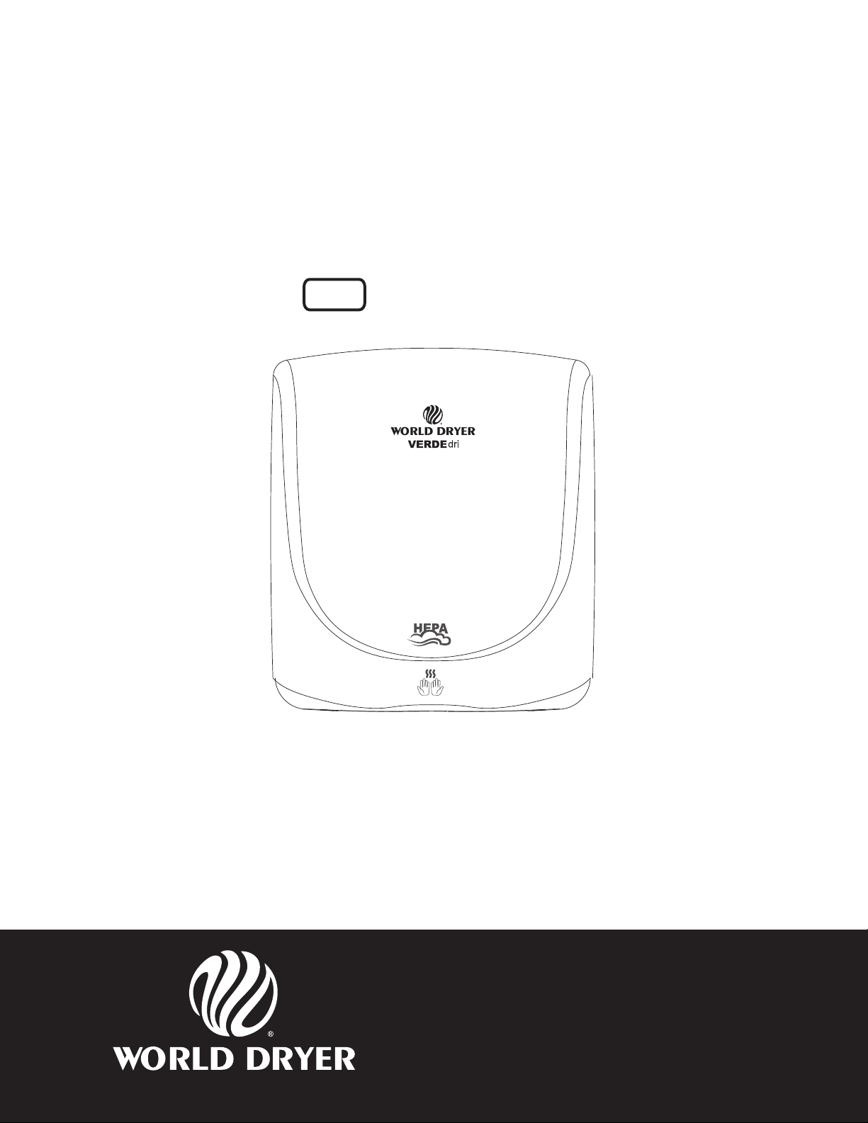
VERDEdri
Hi-Speed Surface-Mounted ADA Compliant Hand Dryer
Secamanos compatible con ADA, de montaje en supercie, de alta velocidad
Sèche-mains grande vitesse monté en surface conforme à l’ADA
Oberächenmontierter ADA-konformer Hochgeschwindigkeits-Händetrockner
Asciugamani elettrico ad alta velocità e conforme ADA per montaggio su supercie
All “Q” Series
Todos los modelos de la serie “Q”
Toutes les séries Q
Alle Geräte der Serie „Q“
Tutti i modelli “Q”
Please read and save these instructions. Read carefully before attempting to assemble, install, operate or service the
product described. Protect yourself and others by observing all safety information. Failure to comply with instructions
could result in personal injury and/or property damage. Retain instructions for future reference.
Por favor lea y guarde estas instrucciones. Léalas cuidadosamente antes de tratar de montar, instalar, operar o dar mantenimiento al producto aquí descrito. Protéjase usted
mismo y a los demás siguiendo todas las instrucciones de seguridad. No seguir las instrucciones puede ocasionar daños, tanto corporales como materiales. Guarde estas
instrucciones como referencia para el futuro.
Lire et conserver ces instructions. Les lire attentivement avant de commencer à assembler, à installer, à faire fonctionner ou à entretenir l’appareil décrit. Pour se protéger et
protéger autrui, observer toutes les consignes de sécurité. Négliger de se conformer à ces instructions peut causer des blessures personnelles et/ou des dommages matériels.
Conserver ces instructions pour références ultérieures.
Bitte lesen Sie diese Anweisungen und bewahren Sie sie auf. Lesen Sie diese Anweisungen sorgfältig durch, bevor Sie das beschriebene Produkt zusammenbauen, montieren,
betreiben bzw. warten. Beachten Sie für Ihren persönlichen Schutz und zum Schutz anderer sämtliche Sicherheitsinformationen. Eine Nichtbeachtung dieser Anweisungen kann zu
Verletzungen und/oder Sachschäden führen. Bewahren Sie die Anweisungen für spätere Bezugnahme auf.
Leggere e conservare queste istruzioni. Leggere con attenzione prima di montare, installare, azionare o riparare il prodotto descritto. Proteggere se stessi e terzi attenendosi alle
istruzioni sulla sicurezza. La mancata conformità alle istruzioni potrebbe comportare lesioni a persone e/o danni a cose. Conservare le istruzioni nel caso occorra consultarle.
World Dryer Corporation
5700 McDermott Drive
Berkeley, IL 60163 U.S.A.
800-323-0701
www.worlddryer.com
1
68-10289 Rev01
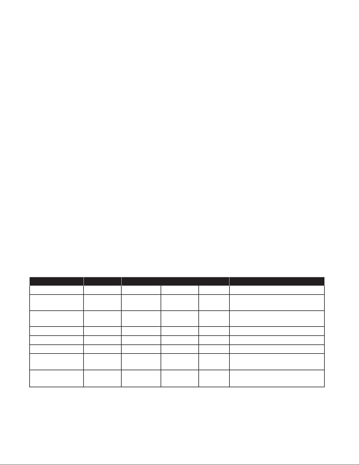
Description
World warm air hand dryer is a surface-mounted ADA (American Disabilities Act) compliant dryer powered by a universal
brushed motor, and delivers up to 950 watts of drying power. These models operate at all voltages 115 – 230VAC,
incorporate an integrated heating element, blower speed control and infrared sensor for automatic activation. Your
specic model may include a high efciency particulate absorption (HEPA) lter to remove a minimum of 99.97% of
contaminants at 0.3 microns in size or larger. These models are intended for use in commercial, industrial, ofce and
public facility environments.
Electrical Specications
Table 1
Models Type Electrical Ratings Certications
Q-XXXXX Automatic 115 / 208 / 230 VAC 950W 50/60Hz cETLus, CE, IP24
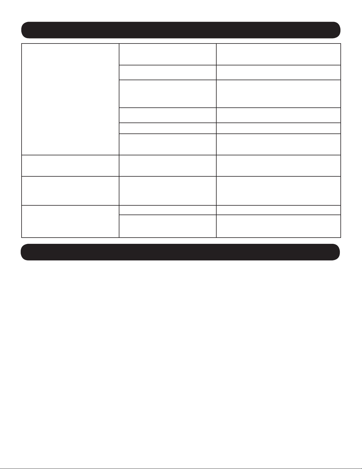
General Safety Information
This appliance is not intended for use by young children or persons with physical, sensory or mental
disabilities unless adequately supervised by a responsible person to ensure they can use the appliance safely.
Young children should be supervised to ensure they do not play with the appliance.
DANGER
injury or death from electric shock.
• Always disconnect the power source before servicing or installing the hand dryer.
Failure to disconnect the power source before installation or servicing can result in serious
DANGER Failure to properly ground this unit could result in severe electrical shock and/or death.
• This hand dryer must be properly grounded for safe operation. An identied ground connection point is supplied on the
hand dryer’s wall base.
• We recommend GFCI protection in wet or damp locations or as required by local code.
WARNING Risk of re, personal injury or property damage are possible if local codes, or safety
recommendations are not followed.
• Installation and servicing should only be performed by qualied electrical technicians.
• Use only the electrical power (voltage and frequency) specied for the model hand dryer being installed. See Table 1 Electrical Specications.
• Connect the hand dryer to the nearest suitable distribution panel. The xed wiring must include a disconnection means
complying with local wiring codes.
• To limit a voltage drop, and insure efcient operation, use No.14 AWG wire or larger as required by local electrical codes.
• Always connect to a branch circuit with circuit breaker or fuse protection with an electrical rating greater than the model
hand dryer’s rated amperage shown in Table 1 - Electrical Specications in accordance with required local electrical
codes such as NEC (National Electrical Code) and/or CEC (Canadian Electrical Code).
• To avoid a hazard due to inadvertent resetting of the thermal cutout, the hand dryer must not be supplied through an
external switching device, such as a timer, or connected to a circuit that is regularly switched on and off by the utility.
• Each automatic model hand dryer must have a dedicated circuit.
• Route all eld wiring away from moving parts within the hand dryer.
• Use ttings with smooth, rounded surfaces for protection of power supply cables as required by local electrical codes
such as The NEC (National Electrical Code) and/or CEC (Canadian Electrical Code).
CAUTION Improper mounting could result in personal injury or property damage.
• Follow the mounting height recommendations in Table 2.
• On a stud wall, one side of the hand dryer should be mounted to an existing stud.
2
Unpacking
1. Remove all packing material. Recycling is recommended.
2. Carefully remove the hand dryer from the shipping carton, using care not to drop the appliance.
3. Inspect carefully for any damage that may have occurred during transit. Check for any loose, missing or damaged
parts. If the hand dryer is damaged, promptly inform the dealer where you purchased it.
Installation
1. Disconnect the power source.
2. Using Table 2 to determine the recommended mounting height, select a mounting location for the hand dryer where no
reective surfaces or objects (such as a hand basin) are directly under the infra-red sensor eye. The infra-red sensor
eye is visible from the bottom of the dryer. The minimum mounting distance from bottom of the dryer to a reective
surface is 18 in (46 cm). When two or more dryers are installed, they should be spaced apart 24 in (61 cm). Avoid
placement where the dryer may be directly exposed to natural light (sunlight).
3. Use the security hex key supplied to turn the cover mounting screws clockwise to remove the cover from the dryer.
4. Using the mounting template provided, mark locations for the mounting bolt holes on the wall. For stud walls, ensure at
least one fastening location will be secured to a stud.
5. Fasten the base to the wall, using the type of bolts recommended in Table 3.
6. Each dryer must have its own dedicated circuit.
7. Connect the dryer to the nearest suitable distribution panel.
8. Replace cover, turn screws counter-clockwise making certain not to over-tighten.
IMPORTANT: Consult local and general regulations before performing dryer installation. Ensure the
electrical network is not overloaded. Always connect to a branch circuit with circuit breaker or fuse
protection with an electrical rating greater than the model hand dryer’s rated amperage shown in Table
1 - Electrical Specications in accordance with the required electrical codes such as NEC (National
Electrical Code) and/or CEC (Canadian Electrical Code).
Table 2
Recommended Mounting Heights from Floor to Dryer Bottom Edge in. (cm.)
Men’s washrooms 46 (117)
Women’s washrooms 44 (112)
Children’s washrooms, ages 4-7 32 (81)
Children’s washrooms, ages 7-10 36 (91)
Children’s washrooms, ages 10-13 40 (102)
Children’s washrooms, ages 13-17 44 (112)
Handicap Mounting Height 37 (94)
Table 3
Type of Wall Type of Bolt Minimum Bolt Length
Hollow Tile, Lath, Wall Board or Metal
Cement, Brick, or Tile Covered Cement or Brick 1/4” (M6) Stud Type Expansion Bolts 3” (76mm)
Stud Wall with wood Backing No 16 (M8) Wood Screws 23/4” (70mm)
1/4” (M6) screw Type or Wing Type
toggle Bolts
3
Dependent on wall
thickness

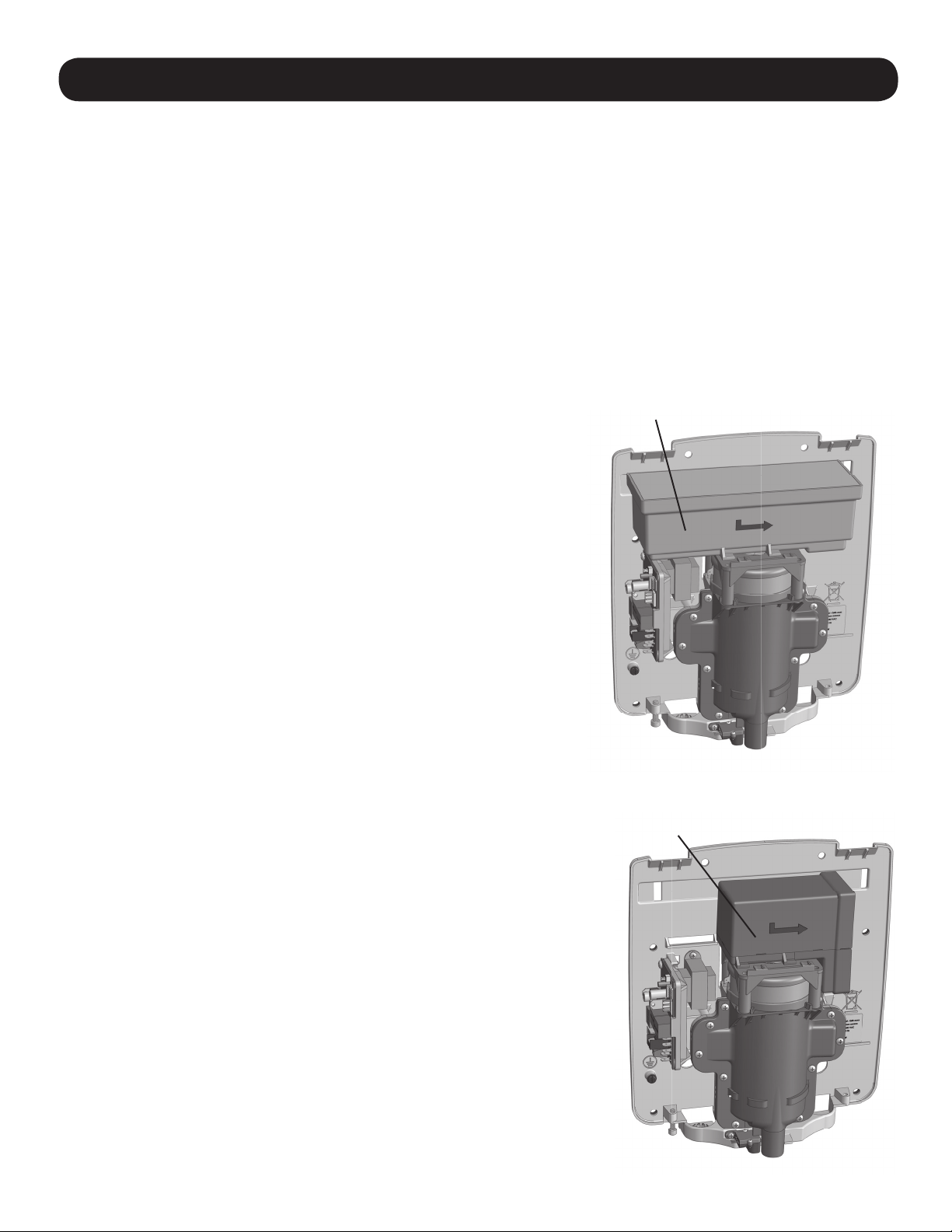
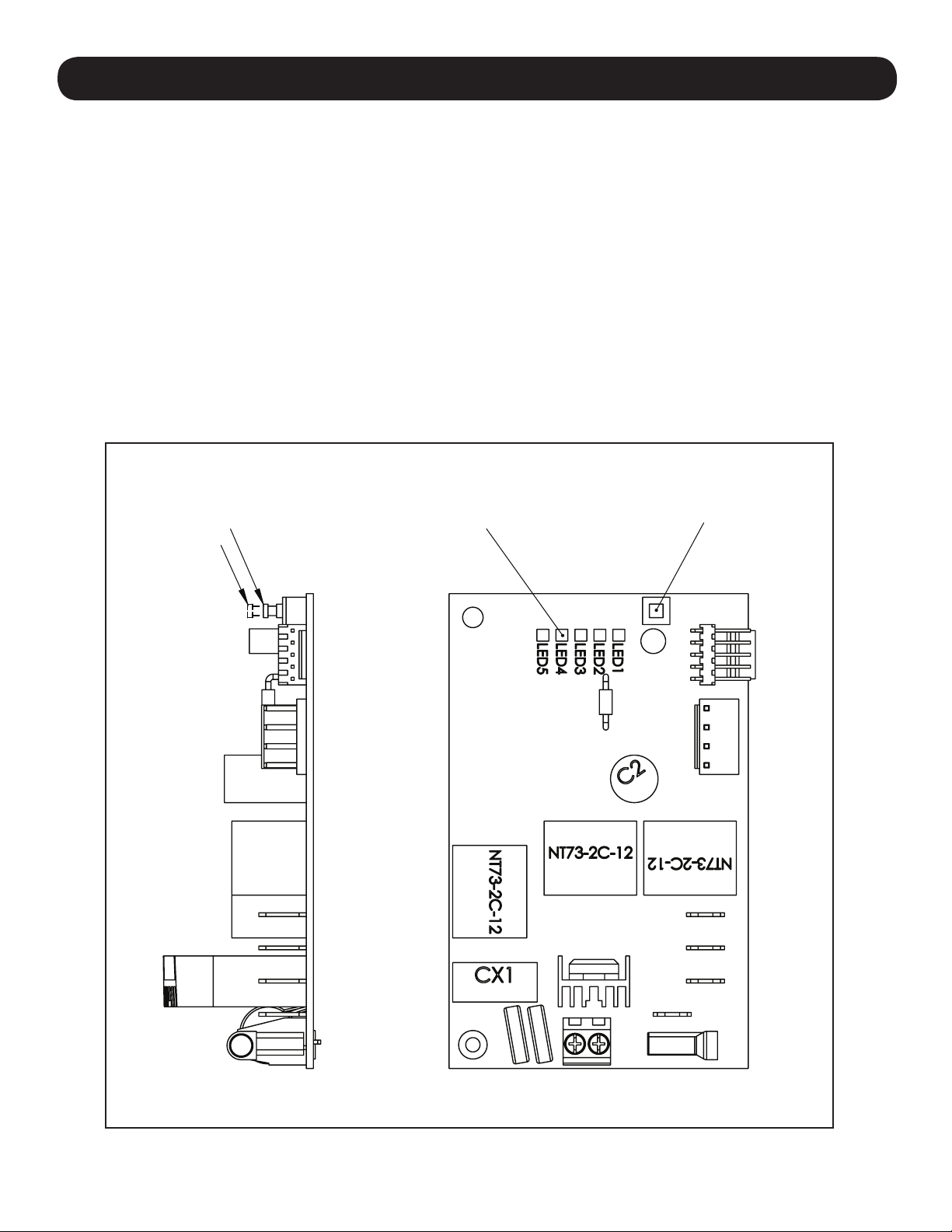
Adjusting Blower Speed
7
1
1
2
4
5
6
9
8
3
These models include adjustable blower speed control for (2) levels of operation – Hi, and Low. The switch is located on
the printed circuit board inside the dryer as shown in Fig. 1 below.
Note: The factory setting for the blower speed control is “Hi”.
To adjust blower speed:
1. Disconnect the power source.
2. Use the security hex key supplied to turn the cover mounting screws clockwise to remove the cover from the dryer.
3. Locate the switch on the printed circuit board inside the dryer as shown in Fig. 1 below, and adjust blower speed as
desired. (Note: When Low speed is selected, LED 4 on the printed circuit board will light “blue”).
Reassemble the dryer cover using the security hex key supplied to turn the cover mounting screws counter-
clockwise and tighten until snug. Do not over tighten.
4. Reconnect the power source.
Figure 1
Hi Speed
Low Speed
Disgnostic
LED’s
Speed Switch
4

Parts List
Repair Parts List For VERDEdri™ Hand Dryer
9
6
1
2
All kits include fasteners needed for
installation.Part Number for Cover Assy.
(Reference Number 7) varies with model
number for hand dryer.
For Repair Parts, visit www.WorldDryer.com
Please provide following information:
- Model number
- Serial number
- Part description and number shown in
parts list
5
3
4
7
#
1 Kit, Dryer Controls with Sensor and Transformer 16-10283K
2 Kit, Motor 32-10268K
3 Kit, Replacement Motor Brushes 32-10337K
4 Kit, Heating Element 21-10306K
5 Kit, Front Plenum – with Seal 47-10270K
6 Kit, Motor Cap 47-10297K
7
(not
shown)
7 Kit, Security Screws (includes Wrench) 46-040221K
8 Wrench, Security 56-40189
9 Filter, HEPA (for models with HEPA lter) 93-10292
10 Filter, Coarse Particulate (for models without HEPA lter) (not shown) 93-10331
Description Part Number
Cover Assy - Alum - White 20-Q974
Cover Assy – Alum – Black 20-Q162
Cover Assy - Alum - Polished Stainless Steel 20-Q972
Cover Assy - Alum - Brushed Stainless Steel 20-Q973
8
1
5
Maintenance and Cleaning Instructions
IMPORTANT: The dryer may collect lint and debris that is naturally present in the air. Excessive build
up of lint and debris can damage the motor and heating element. The dryer should be cleaned on a
routine schedule to maintain the dryer in good operating condition With light to moderate wash room
trafc, cleaning once a year is recommended. If wash room trafc is high, cleaning every 6 months is
recommended.
To clean the hand dryer:
1. Disconnect the power source.
2. Use the security hex key supplied to turn the cover mounting screws clockwise to remove the cover from the dryer.
3. Use a soft-medium bristle paint brush to clean lint, dust and debris from the air intake slots, and the motor’s exterior.
4. After cleaning, reassemble the dryer cover using the security hex key supplied to turn the cover mounting screws
counter-clockwise and tight until snug. Do not over tighten.
HEPA Filter Replacement
(for models including HEPA lters)
Your specic model may include a high efciency particulate absorbtion
(HEPA) lter to remove a minimum of 99.97% of contaminants at 0.3
microns in size or larger.
The service life of a HEPA lter depends on the environment in which the
dryer is installed and frequency of use. High trafc washrooms or high
usage will require more frequent inspection and replacement of the HEPA
lter. The HEPA lter should be inspected at least four times per year in
washrooms with light to moderate trafc and normal environments. In
environments with excessive, dust and debris or in washrooms with high
trafc, inspection of the HEPA lter is recommended on a monthly basis.
When visual inspection of the HEPA lter shows excessive buildup of lint,
dust and debris, the lter should be replaced.
Examining and changing a HEPA lter regularly keeps hand dryers
working efciently. Operating a hand dryer with an excessively dirty or
clogged lter can damage your machine.
The HEPA lter cannot be cleaned and re-used. Do not clean the HEPA
lter or allow it to come into contact with water.
To inspect or replace the HEPA lter:
1. Disconnect the power source.
2. Use the security hex key supplied to turn the cover mounting screws
clockwise to remove the cover from the dryer.
3. Removing and replacing the HEPA lter is easily done by sliding the
lter in its mounting track on the motor cap.
4. After replacing the HEPA lter, reassemble the dryer cover using the
security hex key supplied to turn the cover mounting screws counter-
clockwise and tight until snug. Do not over tighten.
5. Reconnect the power source.
Figure 2
HEPA Filter
Models with HEPA Filter
Coarse Particulate Filter
Models not including HEPA Filters
6
Coarse Particulate Filter
(for models not including HEPA lters)
The dryer has a coarse particulate air lter to prevent lint and debris build up that can damage the
motor and heating element. Routine replacement or cleaning of the air lter is needed to maintain
the dryer in good operating condition. With light to moderate wash room trafc, replacing or
cleaning the air lter once a year is recommended. If the wash room trafc is high, the air lter
should be replaced or cleaned every 6 months. Read complete instruction before proceeding.
To replace or clean the coarse particulate air lter:
1. Disconnect the power source.
2. Use the security hex key supplied to turn the cover mounting screws clockwise to remove the cover from the dryer.
3. Removing and replacing the air lter is easily done by gently pulling the lter away from the lter housing.
4. To clean the coarse particulate air lter, remove from lter from the lter housing. Use soft-medium bristle ½” paint
brush to clean lint, dust and debris from the lter. If air lter cannot be completely cleared of debris, replace the lter.
5. After replacing the air lter into the lter housing, reassemble the dryer cover using the security hex key supplied to
turn the cover mounting screws counter-clockwise and tight until snug. Do not over tighten.
6. Reconnect the power source.
Diagnostic LED’ Display
The printed circuit board includes a set of LED’s that indicate the operational status of the hand dryer. When
contacting World Dryer Technical Service, be prepared to remove the dryer’s cover and provide the condition of
the LED’s as they can be helpful in troubleshooting the dryer. See Figure 1 for location of diagnostic LED’s on the
printed circuit board. See Table 4 for an explanation of LED function.
Diagnostic LED Function
Table 4
IR Sensor Activity Dryer Speed Supply Voltage Detected Indication
LED 5 LED 4 LED 3 LED 2 LED 1
Flashing Flashing Flashing Power Supply Voltage is less than
100V or greater than 255V
OFF OFF Red Power Supply Voltage is 110 –
120V
OFF Yellow Off Power Supply Voltage is 208V
Light Green OFF OFF Power Supply Voltage is 240V
Blue Motor speed is set at low speed
Green (solid) IR sensor detects hands or object
in sensing zone
Flashing Green In vandal-resistant “lock out” mode
(check for sensor obstruction)
7
Troubleshooting Chart
Incoming Power Supply Remove cover and check diagnostic LEDS. If no
Defective PCB If no LED’s are lit above and supply circuit is con-
Sensor Obstruction If LED 5 is lit or ashing (Green) without hands
Dryer fails to start.
Defective Sensor Operation If LED 5 does not light when hands are under
Motor Brushes at End of Service Life Check motor brushes and replace if necessary.
LED’s are lit, check power supply at the circuit
breaker / fuse.
rmed to be active, replace PCB and transformer.
under the sensor, check Sensor Lens for foreign
material or dirt. Clean Lens with soft damp cloth
and mild cleaning agent
sensor, replace PCB and sensor.
Dryer too loud.
Air temperature is too cold. The dryer’s
heating uctuates / goes “on” and “off” during
a drying cycle. The dryer speed uctuates
up and down during a drying cycle.
Dryer will only run a few seconds and then
stops. Dryer will not activate every time.
Arcing sound during operation. Funny
smell (ozone) during operation.
Defective Heating Element
(Important: Applies only when
connected to 208 – 240V power supply)
Dryer Speed Setting Adjust blower speed to “Low”. See page 4. When
Defective Heating Element
(Important: Applies only when
connected to 120V power supply)
Motor Brushes at End of Service Life Check motor brushes and replace if necessary.
Defective Heating Element
(Important: Applies only when con-
nected to 208 – 240V power supply)
If dryer is connected to 208 – 240V power supply
and all other possible causes have been checked,
replace the heating element.
operating at low speed, LED 4 will light (blue)
when hands are under sensor.
Replace heating element.
Replace heating element.
Limited Warranty
World LIMITED FIVE – YEAR WARRANTY. World Warm Air Hand Dryer, Model covered in this manual, is warranted by World Dryer Corporation to the origi-
nal user against defects in workmanship or materials under normal use for 5 years after date of purchase excluding normal wear and tear, or expendable parts such
as HEPA lters, motor brushes, etc. Any part which is determined to be defective in material or workmanship and returned to an authorized service location, as World
designates, shipping costs prepaid, will be, as the exclusive remedy, repaired or replaced at World’s option. For limited warranty claim procedures, see PROMPT
DISPOSITION below. This limited warranty gives purchasers specic rights from jurisdiction to jurisdiction.
LIMITATION OF LIABILITY. To the extent allowable under applicable law, World’s liability for consequential and incidental damages is expressly disclaimed.
World’s liability in all events is limited to and shall not exceed the purchase price paid.
WARRANTY DISCLAIMER. World has made a diligent effort to provide product information and illustrate the products in this literature accurately; however,
such information and illustrations are for the sole purpose of identication, and do not express or imply a warranty that the products are MERCHANTABLE, or FIT FOR
A PARTICULAR PURPOSE, or that the products will necessary conform to the illustrations or descriptions. Except as provided below, no warranty or afrmation on
fact, expressed or implied, other than as stated in the “LIMITED WARRANTY” above is made or authorized by World.
PRODUCT SUITABILITY. Many jurisdictions have codes and regulations governing sales, construction, installation, and/or use of products for certain purposes,
which may vary from those in neighboring areas. While World attempts to assure that the products comply with such codes, it cannot guarantee compliance, and can
not be responsible for how the product is installed or used. Before purchase and use of a product, review the product application, and all applicable national and local
codes and regulations, and be sure that the product, installation, and use will comply with them.
Certain aspects of disclaimers are not applicable to consumer products; e.g., (a) some jurisdictions do not allow the exclusion or limitation of incidental or consequential damages, so the above limitation or exclusion may not apply to you; (b) also, some jurisdictions do not allow a limitation on how long an implied warranty lasts,
consequentially the above limitation may not apply to you; and (c) by law, during the period of this Limited Warranty, and implied warranties of implied merchantability
or tness for particular purpose applicable to consumer products purchased by consumers, may not be excluded or otherwise disclaimed.
Manufactured by World Dryer Corporation, Berkeley, Illinois 60163 U.S.A
PROMPT DISPOSITION. World will make a good faith effort for prompt correction or other adjustment with respect to any product which proves to be defective
within limited warranty. For any product believed to be defective within limited warranty, rst write or call dealer from whom the product was purchased. Dealer will
give additional directions. If unable to resolve satisfactorily, write to World at address below, giving dealer’s name, address, date, and number of dealer’s invoice, and
describing the nature of defect. Title and risk of loss pass to buyer on delivery to common carrier. If product was damaged in transit to you, le claim with carrier.
8
Descripción
El secamanos de aire caliente World Warm Air es un aparato que se monta sobre una supercie, que cumple con la ley ADA (Ley
Estadounidense para Discapacitados) y que funciona con un motor universal de escobillas que genera 950 vatios de potencia de
secado. Estos modelos funcionan a todas las tensiones de 115 a 230 VCA, disponen de un elemento calefactor integrado, un control
de velocidad del ventilador y un sensor de rayos infrarrojos para su activación automática. Su modelo especíco puede incluir un
ltro de absorción de partículas de alta eciencia (HEPA) para eliminar un mínimo del 99,97% de los contaminantes de 0,3 micras de
tamaño o más grandes. Estos modelos están diseñados para entornos comerciales, industriales, de ocinas e instalaciones públicas.
Especicaciones del sistema eléctrico
Tabla 1
Modelos Tipo Clasicaciones eléctricas Certicaciones
Q-XXXXX Automático 115 / 208 / 230 VCA 950W 50/60Hz cETLus, CE, IP24
Información de seguridad general
Este aparato no está hecho para que lo utilicen niños pequeños o personas con capacidades físicas, sensoriales o
mentales disminuidas, a menos que sean supervisados por una persona responsable y puedan utilizar el aparato
de manera segura. Hay que supervisar a los niños pequeños para que no jueguen con el aparato.
PELIGRO No desconectar el suministro eléctrico antes de realizar la instalación o el mantenimiento puede
resultar en lesiones graves o la muerte por descarga eléctrica.
• Desconecte siempre el suministro eléctrico antes de instalar el secamanos o efectuar su mantenimiento.
PELIGRO No conectar correctamente a tierra esta unidad puede resultar en una descarga eléctrica grave
o la muerte.
• Este secamanos se debe conectar correctamente a tierra para que funcione en forma segura. En la base del secamanos se
identica un punto de conexión a tierra.
• Recomendamos utilizar un protector GFCI (interruptor de circuito por pérdidas accidentales a tierra) en lugares mojados o
húmedos, o donde lo exija el código local.
ADVERTENCIA Hay riesgos posibles de incendio, lesiones personales o daños materiales si no se
cumple con los códigos locales o las recomendaciones de seguridad.
• La instalación y el mantenimiento deben ser realizados únicamente por técnicos eléctricos cualicados.
• Utilice únicamente la energía eléctrica (voltaje y frecuencia) especicada para el modelo de secamanos que se esté
instalando. Consulte la Tabla 1 - Especicaciones del sistema eléctrico.
• Conecte el secamanos al tablero de distribución adecuado más cercano. El cableado jo debe incluir un medio de
desconexión que cumpla con los códigos de cableado locales.
• Para limitar las caídas de voltaje y garantizar un funcionamiento eciente, utilice un cable de calibre AWG 14 o mayor de
acuerdo con los requisitos de los códigos eléctricos locales.
• Conecte siempre a un ramal que tenga instalado un disyuntor o un fusible protector cuya capacidad eléctrica supere la
intensidad nominal del modelo del secamanos, como se indica en la Tabla 1: Especicaciones del sistema eléctrico, de
acuerdo con los códigos eléctricos locales tales como el Código Eléctrico Nacional (NEC) y el Código Eléctrico Canadiense
(CEC).
• Para evitar el peligro de reconectar accidentalmente el interruptor térmico, el secamanos no debe alimentarse a través de un
dispositivo conmutador externo como, por ejemplo, un temporizador, ni conectarse a un circuito que la empresa de servicio
eléctrico cierre o abra regularmente.
• Todo secamanos de modelo automático debe tener un circuito especial.
• Tienda todo el cableado durante la instalación separándolo de todas las piezas móviles del interior del secamanos.
• Use acoplamientos con supercies lisas y redondeadas para la protección de los cables de suministro eléctrico de acuerdo
con los códigos eléctricos locales tales como el Código Eléctrico Nacional (NEC) y el Código Eléctrico Canadiense (CEC).
ATENCIÓN El montaje incorrecto puede ocasionar lesiones corporales o daños materiales.
• Cumpla con las alturas de montaje recomendadas en la Tabla 2.
• En una pared de entramado, se debe montar un lado del secamanos en un parante existente.
9
Desembalaje
1. Retire todos los materiales de embalaje. Se recomienda reciclar los materiales.
2. Extraiga cuidadosamente el secamanos de la caja de envío, sin dejar caer el aparato.
3. Inspeccione el producto cuidadosamente para vericar si se han producido daños durante el transporte. Revise para
vericar si hay piezas sueltas, que falten o estén dañadas. Si el secamanos está dañado, informe inmediatamente al
concesionario donde compró el secamanos.
Instalación
1. Desconecte el suministro eléctrico.
2. Siguiendo las alturas de montaje recomendadas en la Tabla 2, seleccione un lugar donde montar el secamanos que
no tenga supercies ni objetos reectantes (p. ej., un lavamanos) directamente debajo del sensor de rayos infrarrojos.
La célula fotoeléctrica infrarroja es visible desde la parte inferior del secamanos. La separación de montaje mínima
entre la parte inferior del secador y cualquier supercie reectante es 46 cm (18 pulg.). Cuando se instalan dos o
más secadores, deben separarse al menos 61 cm (24 pulg.). No coloque el secamanos donde pueda estar expuesto
directamente a la luz natural (luz solar).
3. Utilice la llave hexagonal de seguridad que se proporciona para girar los tornillos de montaje de la cubierta hacia la
derecha, y separarla del secamanos.
4. Utilice la plantilla proporcionada para marcar la ubicación de los agujeros de los tornillos de montaje en la pared.
Para paredes de entramado, asegúrese de jar al menos un punto de sujeción a un parante.
5. Sujete la base a la pared mediante el tipo de pernos recomendado en la Tabla 3.
6. Cada secamanos debe tener su propio circuito especial.
7. Conecte el secamanos al tablero de distribución adecuado más cercano.
8. Coloque nuevamente la cubierta, gire los tornillos hacia la izquierda y asegúrese de no apretarlos demasiado.
IMPORTANTE: Consulte los reglamentos locales y generales antes de realizar la instalación del
secamanos. Asegúrese de que la red eléctrica no esté sobrecargada. Conecte siempre a un ramal
que tenga instalado un disyuntor o un fusible protector cuya capacidad eléctrica supere la intensidad
nominal del modelo del secamanos, como se indica en la Tabla 1: Especicaciones del sistema
eléctrico, de acuerdo con los códigos eléctricos requeridos tales como el Código Eléctrico Nacional
(NEC) y el Código Eléctrico Canadiense (CEC).
Tabla 2
Alturas de montaje recomendadas desde el suelo hasta la parte inferior del secamanos cm (pulg.)
Baños de hombres 117 (46)
Baños de mujeres 112 (44)
Baños de niños, 4 a 7 años de edad 81 (32)
Baños de niños, 7 a 10 años de edad 91 (36)
Baños de niños, 10 a 13 años de edad 102 (40)
Baños de niños, 13 a 17 años de edad 112 (44)
Altura de montaje para discapacitados 94 (37)
Tabla 3
Tipo de pared Tipo de perno Longitud mínima del perno
Baldosa hueca, malla, pared de yeso o metal
Cemento, ladrillo, o cemento o ladrillo
recubiertos con baldosas
Pared de entramado con refuerzo de madera Tornillos para madera (M8) número 16 70 mm (2 3/4 pulg.)
Pernos acodillados roscados (M6) o de
palomilla de 1/4 pulg.
Pernos de expansión de tipo parante
(M6) de 1/4 pulg.
10
Depende del grosor de la
pared
76 mm (3 pulg.)
Ajuste de velocidad del ventilador
Estos modelos incluyen un control de velocidad del ventilador ajustable para (2) niveles de operación - Alto y Bajo. El
interruptor se encuentra en la placa de circuitos impreso dentro del secamanos, mostrado en la gura 1 a continuación.
Aviso: La conguración inicial de fábrica del control de velocidad del ventilador es “Alto”.
Para ajustar la velocidad del ventilador:
1. Desconecte el suministro eléctrico.
2. Utilice la llave hexagonal de seguridad que se proporciona para girar los tornillos de montaje de la cubierta hacia la
derecha,
3. Localice el interruptor del tablero de circuitos impresos dentro del secamanos como se muestra en la gura 1 a
continuación, y ajuste la velocidad del ventilador según se desee. (Aviso: Cuando se selecciona la velocidad “Baja”,
la luz LED 4 del tablero de circuitos impresos se encenderá de color “azul”).
Instale nuevamente la cubierta del secamanos, usando la llave hexagonal de seguridad suministrada para girar
los tornillos de montaje de la cubierta
demasiado.
4. Vuelva a conectar el suministro eléctrico.
Figura 1
y separarla del secamanos.
hacia la izquierda y apriételos hasta que estén bien ajustados. No apriete
Velocidad baja
Velocidad alta
Luces LED de
diagnóstico
Interruptor de velocidad
11
 Loading...