

Page 1
Model A
Heavy Duty Hand Dryer
Secamanos Resistente . Sèche-mains robuste
Heavy-Duty-Händetrockner . Asciugamano elettrico per uso intensivo
All (D)XA, (D)A Series
Todos los Modelos de las Series (D)XA y (D)A
Toutes les modèles de série (D)XA et (D)A
Alle Modelle der Serien (D)XA und (D)A
Tutti i modelli delle serie (D)XA e (D)A
Please read and save these instructions. Read carefully before attempting to assemble, install, operate or service the product described.
Protect yourself and others by observing all safety information. Failure to comply with instructions could result in personal injury and/or
property damage. Retain instructions for future reference.
Por favor lea y guarde estas instrucciones. Léalas cuidadosamente antes de tratar de montar, instalar, operar o dar mantenimiento al producto aquí descrito. Protéjase usted mismo y a los demás
observando toda la información de seguridad. No seguir las instrucciones puede ocasionar daños,
tanto personales como materiales. Guarde estas instrucciones para referencia en el futuro.
Lire et conserver ces instructions. Les lire attentivement avant de commencer à assembler, installer, faire fonctionner, réparer ou entretenir l’appareil décrit. Pour se protéger et protéger autrui, observer
toutes les consignes de sécurité. Le fait de négliger d’appliquer ces instructions peut entraîner des blessures et/ou des dommages matériels. Conserver ces instructions pour consultation ultérieure.
Bitte lesen Sie diese Anweisungen und bewahren Sie sie auf. Lesen Sie diese Anweisungen sorgfältig durch, bevor Sie das beschriebene Produkt zusammenbauen, montieren, betreiben bzw. warten.
Beachten Sie für Ihren persönlichen Schutz und zum Schutz anderer sämtliche Sicherheitsinformationen. Eine Nichtbeachtung dieser Anweisungen kann zu Verletzungen und/oder Sachschäden führen.
Bewahren Sie die Anweisungen für spätere Bezugnahme auf.
Leggere e conservare queste istruzioni. Leggere con attenzione prima di montare, installare, azionare o riparare il prodotto descritto. Proteggere sé stessi e terzi attenendosi alle istruzioni sulla sicurezza.
La mancata conformità alle istruzioni potrebbe comportare lesioni a persone e/o danni a cose. Conservare le istruzioni nel caso occorra consultarle.
World Dryer Corporation
5700 McDermott Drive
Berkeley, IL 60163 U.S.A.
800-323-0701
www.worlddryer.com
1
Page 2
Description
World Dryer warm air hand dryer, powered by a high speed universal motor, delivering 2300 Watts of drying power. This hand dryer
runs on 115 Volts AC, 208/220-240 Volts AC, or 277 volts AC electrical supply, depending on model. Automatic and push-button
models are represented in this product group. This appliance is intended for use in hand drying, contributing to hygienic and cost
effective hand sanitation. This hand dryer may be used in commercial, industrial, ofce and public facility environments.
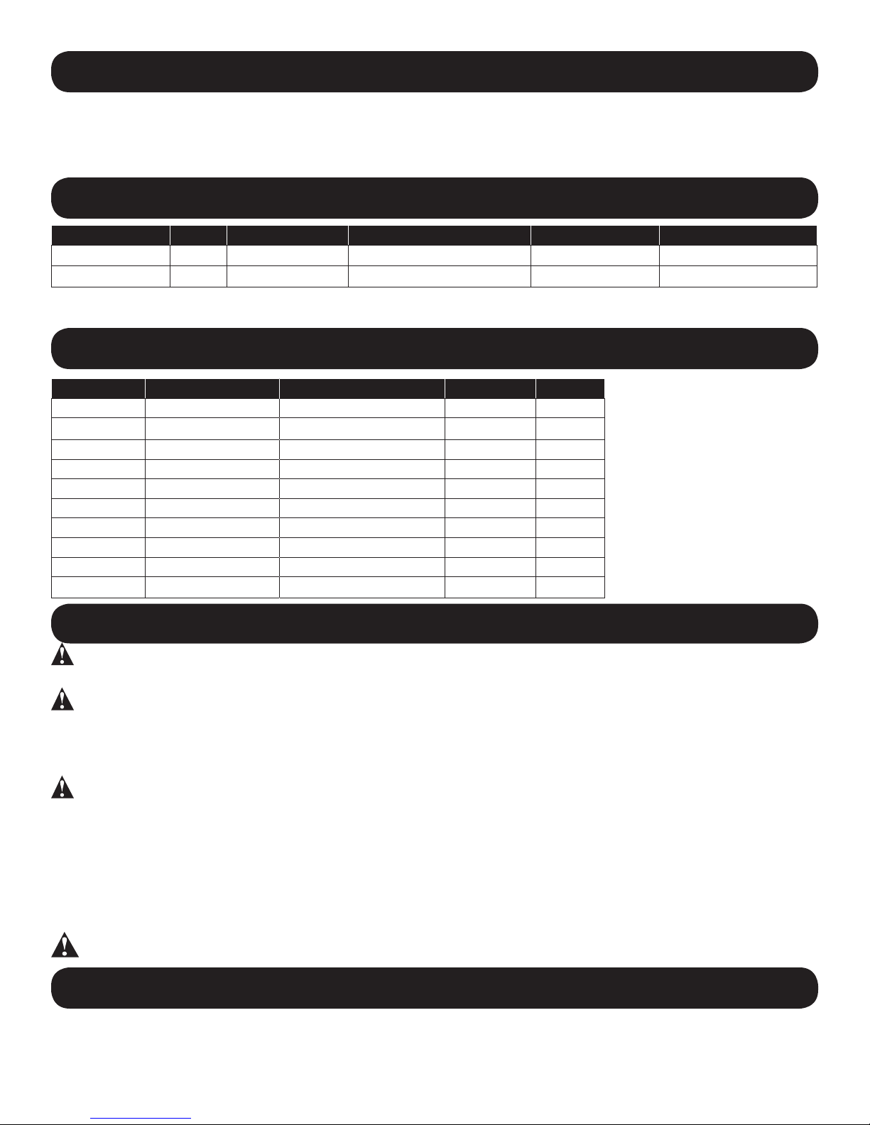
General Specications
Basic Models Nozzle Drying Cycle Dimensions (WxDxH) Weight Cover Material
(D)XA Fixed Automatic 11.38” x 9.62” x 8.12” 18 / 29 lbs Steel/Cast Iron
(D)A Fixed* 30/40 Seconds 11.38” x 9.62” x 8.12” 18 / 29 lbs Steel/Cast Iron
(*) Rotating Nozzle Option
Electrical Specications
Models Type Electrical Input Amperage Watts
(D) XA5 Automatic 115 VAC, 60 Hz 20 2300
(D) A5 Push-button 115 VAC, 60 Hz 20 2300
(D) XA52 Automatic 115 VAC, 60 Hz 15 1725
(D)A52 Push-button 115 VAC, 60 Hz 15 1725
(D) XA54 Automatic 208-230 VAC, 60 Hz 10 2300
(D)A54 Push-button 208-230 VAC, 60 Hz 10 2300
(D) XA548 Automatic 220-240 VAC, 50 Hz 10 2300
(D)A548 Push-button 220-240 VAC, 50 Hz 10 2300
(D) XA57 Automatic 277 VAC, 60 Hz 8.5 2300
(D)A57 Push-button 277 VAC, 60 Hz 8.5 2300
(cULus Listed, E19860,
CE TUV-GS)
General Safety Information
DANGER
• Always disconnect the power source before servicing or installing the hand dryer.
DANGER
• This hand dryer must be properly grounded (Earthed) for safe operation. An identied ground connection point is supplied on the
hand dryer’s wall base.
• We recommend GFCI protection in wet or damp locations or as required by local code.
WARNING
• Use only the electrical power (voltage and frequency) specied for the model hand dryer being installed.
• Connect the hand dryer to the nearest suitable distribution panel.
• To limit a voltage drop, and insure efcient operation, use wire gauge as required by local or National Electrical Code.
• Do not connect to a branch circuit with CB or fuse protection over 20 Amps. This is in compliance with The National Electrical Code
#210-20.
• All automatic model hand dryers must have a dedicated 20 Amp circuit as required by Underwriters Laboratories, Inc. (UL).
• Route all eld wiring away from any moving parts within the hand dryer.
Failure to disconnect the power source before installation or servicing can
result in serious injury or death from electric shock.
Failure to properly ground this unit could result in severe electrical shock
and/or death.
Risk of re, personal injury or property damage are possible if local codes,
NEC codes or safety recommendations are not followed.
CAUTION Improper mounting could result in personal injury or property damage.
Unpacking
1. Remove all packing material. Recycling is recommended.
2. Carefully remove the hand dryer from the shipping carton, using care not to drop the appliance.
3. Inspect carefully for any damage that may have occurred during transit. Check for any loose, missing or damaged parts. If the
hand dryer is damaged, promptly inform the shipper or dealer where you purchased it.
2
Page 3
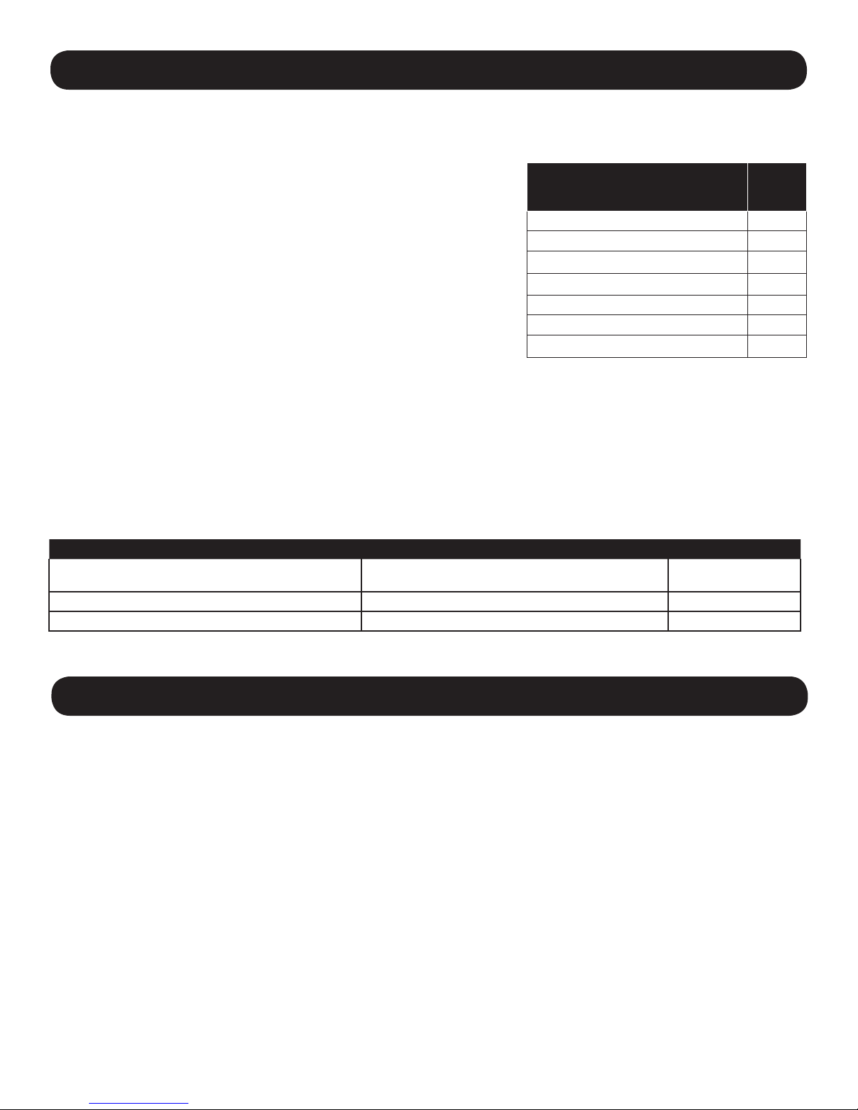
Installation
IMPORTANT: Consult local and general regulations before performing dryer installation. Make certain that the electrical
network is not overloaded. Do not connect to a branch circuit with a circuit breaker or fuse rated over 20 Amps. This is a UL
recommendation and complies with NEC #210-20.
FOR MODELS (D)A5, 52, 54, 548, 57
1. Disconnect the power source.
2. Use the security Allen wrench supplied to remove the (2) cover mounting screws.
Remove the cover from the dryer.
3. Place the hand dryer base on the wall at the desired location using Table 1 to
determine the recommended mounting height. With the base so located, use it as
a template to mark locations of the 4 mounting bolt holes on the wall. When two or
more dryers are installed, they should be spaced 24” (61 cm) minimum from center
to center.
4. Fasten the base to the wall, using the type of bolts suggested in Table 2.
5. Connect the dryer to the nearest suitable distribution panel.
6. Replace cover, making certain not to over-tighten cover bolts.
FOR AUTOMATIC DRYER MODELS (D)XA5, 52, 54, 548, 57
1. Disconnect the power source.
2. Use the security Allen wrench supplied to remove the (2) cover mounting screws. Remove the cover from the dryer.
3. Place the hand dryer base on the wall at the desired location using Table 1 to determine the recommended mounting height. With the
base so located, use it as a template to mark locations of the 4 mounting bolt holes on the wall. When two or more dryers are installed,
they should be spaced 24” (61 cm) minimum from center to center. Applies only to the Automatic models: ensure that no reective
object (such as a hand basin) is located directly under the infra-red sensor eye; the minimum distance is 18 inches.
4. All automatic dryers must have their own dedicated 20 amp circuit. This is a UL-suggested requirement.
IMPORTANT: Consult local and general regulations before performing dryer installation. Ensure that the electrical network is not
overloaded. Do not connect to a branch circuit over 20 amps.
Table 1
Recommended Mounting Heights
from Floor to Dryer Bottom Edge
Men’s washrooms 46 (117)
Women’s washrooms 44 (112)
Children’s washrooms, ages 4-7 32 (81)
Children’s washrooms, ages 7-10 36 (91)
Children’s washrooms, ages 10-13 40 (102)
Children’s washrooms, ages 13-17 44 (112)
Handicap Mounting Height 37 (94)
in. (cm.)
Table 2
Type of Wall Type of Bolt Minimum Bolt Length
Hollow Tile, Lath, Wall Board or Metal 1/4” (M6) Screw Type or Wing Type Toggle Bolts Dependent on wall thickness
Cement, Brick, or Tile Covered Cement or Brick 1/4” (M6) Stud Type Expansion Bolts 3” (76 mm)
Stud Wall with Wood Backing No.16 (M8) Wood Screws 23/4” (70 mm)
NOTE: When using surface mount wiring, an optional, available offset tting #100BR must be ordered to adapt the wiring to 1/2” EMT.
Maintenance
NOTE: Disconnect The Power Before Performing Any Of The Following
CLEANING INSTRUCTIONS:
Read complete Instructions before proceeding. Under normal use, cleaning the Dryer once a year will keep it in good operating
condition. If the washroom trafc is heavier than normal, the cleaning should be done every 6 months. Lint and dust build up inside the
dryer can result in damage to motor and heating element as well as hot emissions that could injure the user.
1. Remove two cover mounting screws from dryer cover using security Allen wrench provided. Support cover while removing screws.
2. Remove three (3) side screws holding blower housing together. Note position of heating element and protective screen. The lead
wires are directed through the clearance hole in the blower housing halves. Carefully remove the heating element however, do not
disconnect the wires.
3. Clean blower wheel halves using a 1/2“ diameter radial bristle brush. Insert brush through space between individual blades and
dislodge dirt. Do not bend or damage blades.
4. Vacuum out dirt from blower and housing, reposition heating element, protective screen and housing half and replace three (3) side
screws. Tighten gently making sure that mica heating element pieces are positioned in housing slots with connecting wires passing
through blower housing hole.
5. Use soft-medium bristle 1/2“ paint brush to clean dust and dirt from motor and switch timer. Do not bend switch blade when cleaning.
6. Use a stiff brush to clean dirt from inside of nozzle grill and inlet grill. Water may be necessary to ush dirt from inlet grill. Dry inside
of cover before replacing if water is used.
7. Inspect motor brushes. To inspect brushes insert tooth pick in hole in end of brush assembly. If tooth pick is inserted more than one
inch, replace brushes. (See replacement instructions.)
8. Replace cover. Place cover squarely over base and push ush to wall. Insert 2 cover mounting screws and tighten until snug. Do
not over-tighten.
3
Page 4
REPLACEMENT OF MOTOR BRUSHES
1. Remove locking spring clip securing brush holder.
2. Draw brush cap out of motor slowly until wire connector appears.
3. Detach wire connector and remove brush and holder assembly.
NOTE: When unpacking brush assembly from carton it is important to hold carbon brush in brush holder securely. P/N206NL
4. Insert new assembly to point where wire quick connect connection can be made.
5. Push brush quick-connects on motor and brush sleeve together.
6. Push brush assembly back in place and insert locking spring clip.
REPLACEMENT OF HEATING ELEMENT
1. Remove three screws holding blower housing (#211P and #112P) together, and remove #112P side of housing.
2. Disconnect the white wires of the heating element at the terminal block and switch terminal. Replace with the new heating element
of proper voltage and wattage, being careful to connect it identically to the old one.
3. Hold element in position on stationary side of blower housing and slip removable side in place, making sure element frames t into
grooves in blower housing and both wires run through notch at top of air outlet. Reinstall the protective screen and replace three
screws fastening blower housing together.
4. Reconnect wires to terminal block and switch. Make certain all wires are properly reconnected and match the wiring diagram.
REPLACEMENT OF SWITCH TIMER ON PUSH-BUTTON MODELS
1. Remove screws from each of the two terminals on switch timer, marking wires for correct reconnection to switch terminals.
2. Replace defective timer with new one. (Specify Dryer Model when ordering Timer.)
3. Reconnect wires to terminals.
4. Replace cover (be sure cover ts squarely over base unit) and push in until cover is ush with wall and insert two cover mounting
screws. Do not over-tighten the mounting screws.
5. Turn on power to dryer.
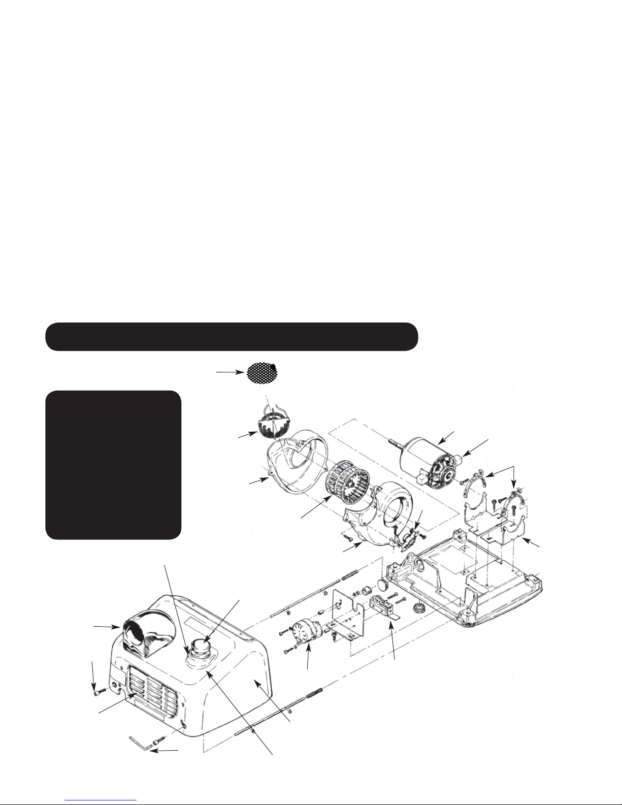
Parts List
For Repair Parts, visit
www.WorldDryer.com.
Please provide following
information:
Model number
Serial number
Part description and
number shown in parts list
12
13
19
18
17
14
16
15
20
1
2
3
4
11
10
9
6
5
Figure 2 - Repair Parts List For
7
8
4
Hand Dryers
Page 5

Description Part Number Qty.
#
1 Motor - 115 V (D)A5, (D)XA5, (D)A52, (D)XA52 210K 1
Motor - 208/220-240 V (D)A54, (D)XA54, (D)A548, (D)XA548, †(D)A57, †(D)XA57 210ACEK 1
2 Motor Brush 206NL 2 Req’d
3 Motor Mounting Strap 110-4A 2 sets
4 Motor Mounting Brackets 110-4 2
5 Micro Switch Only (D)A(All) 143F 1
6 Switch Timer Unit - 115 V, 30 Seconds (D)A5, (D)A52 225 1
Switch Timer Unit - 208-230 V, 30 Seconds (D)A54 225A 1
Switch Timer Unit - 220-240 V, 50 Hz, 30 Seconds (D)A548 225M 1
Switch Timer Unit - 277 V, 30 Seconds (D)A57 225A7 1
7 Cover Complete, Cast Iron, Automatic, White XA(All)* 70XA5-974AK 1
Cover Complete, Cast Iron, Pushbutton, White A(All)* 70A5-974AK 1
Cover Complete, Steel, Automatic, White DXA(All)* 72DXA5-974K 1
Cover Complete, Steel, Pushbutton, White DA(All)* 72DA5-974K 1
Cover Complete, Stainless Steel, Auto/Pushbutton* Call to order 1
8 Pushbutton Retaining Ring, Insulated Push Rod Tip, and Spring Kit (D)A(All) 193K 1
9 Security Allen Wrench 204TP 1
10 Inlet Grill, Cast Iron, Pushbutton, with Mtg. Hardware A(All) 194-1K 1
Inlet Grill, Cast Iron, Automatic, with Mtg. Hardware XA(All) 194-1BK 1
11 Tamper Proof Cover Screw, Cast Iron Covers 100B2 2
Tamper Proof Cover Screw, Steel Covers 46-330 2
Lock Washer, Steel Covers 59-005028 2
12 Nozzle Assembly Kit 34-172K 1
13 Pushbutton Adapter, Gasket and Bushing Unit (D)A(All) 190K 1
14 Pushbutton Assembly Kit (Knob, Rod, Ring, Spring and Tip) (D)A(All) 185K 1
15 Blower Scroll Half with Base Mount and Thermostat 211PK 1
16 Blower Plastic 101P 1
17 Blower Scroll Half with Terminal Block - Left Side 112P 1
18 Heating Element - 115 V, 20 AMP (D)A5, (D)XA5 213 1
Heating Element - 115 V, 15 AMP (D)A52, (D)XA52 213B 1
Heating Element - 230 V (D)A54, (D)XA54, (D)A548, (D)XA548 213A4 1
Heating Element - 277 V, 8.5 AMP (D)A57, (D)XA57 213A7 1
19 Grid, Ground Assy (All) 12-001 1
20 Thermostat Only 3/4” 1111-03 1
r
Automatic Sensor Control - 115 V (D)XA 16-230-120 (D)A 1
r
Automatic Sensor Control - 208-230 V (D)XA54 16-240-208 (D)A 1
r
Automatic Sensor Control - 220-240 V, 50Hz CE Only (D)XA548 16-230-240 CE 1
r
Infrared Sensor, Eye (D)XA(All) 49-238 1
* Specify model when ordering.
(†) 277 Volt Models Use 210ACEK Motor (230 V Power Tap).
r Not shown.
5
Page 6
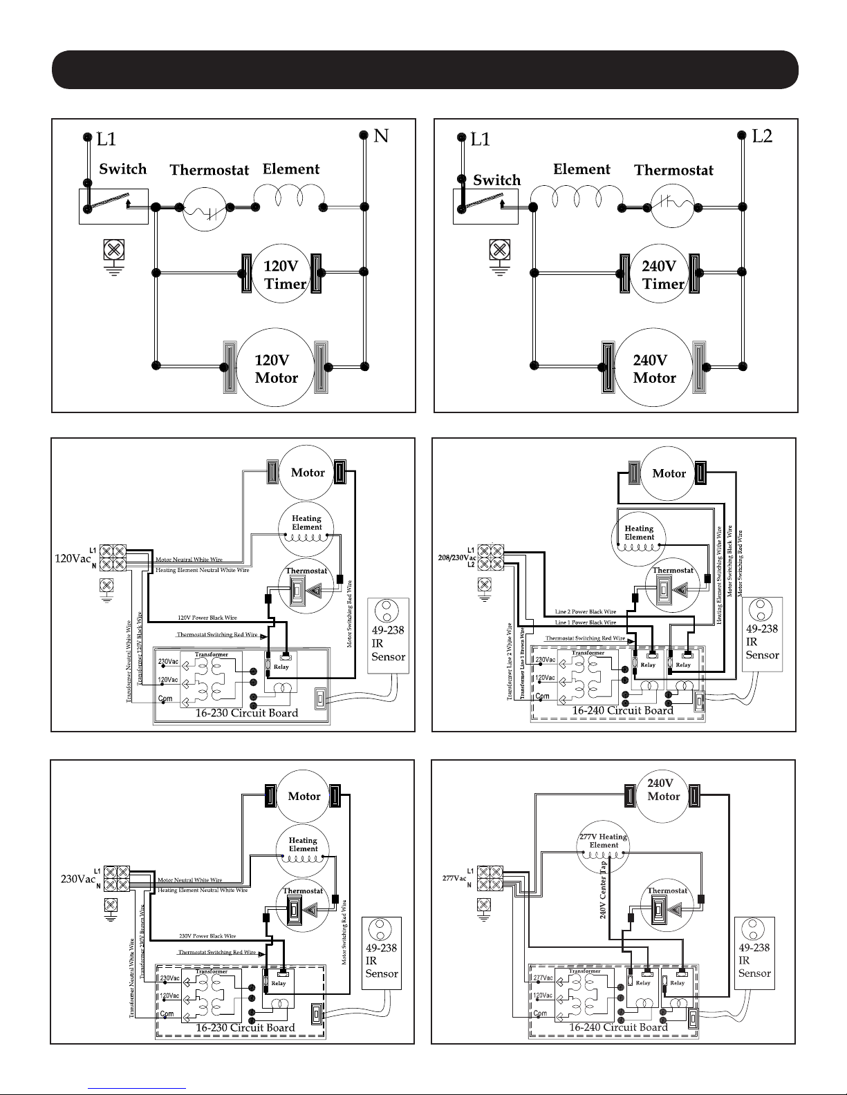
Wiring Diagram
Wiring Diagram - Model (D)A5, A52
Wiring Diagram - Model (D) XA5, (D) XA52
Wiring Diagram - Model (D)A54, A548
Wiring Diagram - Model (D) XA54
Wiring Diagram - Model (D) XA548 Wiring Diagram - Model (D) XA57
6
Page 7

Troubleshooting Chart
Trouble shooting should only be conducted by a qualied electrician.
Symptom Model Possible Cause(s) Corrective Action
Dryer fails to start XA Sensor obstruction 1. Check Sensor Lens for foreign material or dirt. Clean Lens with soft damp cloth and mild
cleaning agent.
2. If Lens is damaged or scratched, replace it.
All No power to the unit Check if power is “ON”
XA Faulty Circuit Board (PCB) and
XA Faulty Motor If Relay “Click” is heard, heating element glows for 1-2 seconds, but unit does not start, replace
A Faulty Timer / Switch
Dryer runs for approx. 100
seconds, then will not restart
Dryer runs continuous and
will not shut-off.
Dryer “Ghosts” starts with
no hands present.
Dryer blows cold air. All Defective Heating Element
Dryer air too hot. All Machine is dirty 1. Inspect for foreign material. Using a soft brush and vacuum, clean fan and motor.
Dryer noisy or vibrates. All Fan not centered in housing
XA Sensor obstruction 1. Check Sensor Lens for foreign material or dirt. Clean Lens with soft damp cloth and mild
A Faulty Timer With Dryer Cover Removed, depress the Timer Switch Blade;
XA Sensor receiving false signal or
Sensor
Faulty Motor
reection
Or
Fluctuating power supply
Or Defective Thermostat
■ Foreign object in Fan.
■ Broken or bent Fan.
■ Bent Motor shaft.
Check electrical connections.
Place hands under Sensor. Listen for PCB .
Relay “Click.” If no “Click” is heard, replace the PCB and Sensor.
the Motor.
With Dryer Cover Removed, depress the Timer Switch Blade;
a. Timer Motor should turn.
b. With an Ohm Meter, check for continuity across the Switch Terminals.
“No” in either test, replace Timer Assembly;
“Yes” in both tests, replace Motor.
cleaning agent.
2. If Lens is damaged or scratched, replace the sensor.
Timer Motor should turn. “No” replace Timer Assembly.
1. Hand Dryer should be mounted a minimum of 18” above a reective surface.
2. Check if other Infrared operated appliance in the vacinity may be triggering the Dryer.
3. Multiple Hand Dryers on one circuit or Dryers sharing a lighting circuit. Automatic Hand Dryers
must be on dedicated circuits.
4. Building wiring may be insufcient gauge or too long of a run from the supply.
5. Replace the PCB and Sensor.
1. Check for break in Element Wire.
2. Check Heating Element and Thermostat for continuity. If open, replace as necessary.
2. Replace motor if running slow or erratic.
1. Fan may be rubbing against edge of Fan Housing. To center Fan;
a. On plastic fan unit, carefully “tap” the Fan Hub with a screw driver & small hammer to center it
until the Fan turns freely.
b. On metal fans, loosen the set screw and adjust the fan until it turns freely.
1. Inspect for foreign material. Using a soft brush and vacuum, clean fan and motor.
1. Replace Fan.
1. Replace Motor.
Limited Warranty
WORLD DRYER LIMITED WARRANTY. World dryer™ warm air hand dryers, North American models covered in this manual, are warranted by world dryer corpora-
tion to the original owner against defects in workmanship or materials under normal use for ten years and ve years for electronic controls after the date of purchase. Export
models covered in this manual are warranted for ve years from date of purchase. Normal wear or abuse of any component is excluded from this warranty. Any part which
is determined to be defective in material or workmanship and returned, shipping costs prepaid, will be, as the exclusive remedy, repaired or replaced at world’s option. For
limited warranty claim procedures, see “PROMPT DISPOSITION” below. This limited warranty gives purchasers specic legal rights which vary from jurisdiction to jurisdiction.
LIMITATION OF LIABILITY. To the extent allowable under applicable law, World’s liability for consequential and incidental damages is expressly disclaimed. World’s
liability in all events is limited to and shall not exceed the purchase price paid.
WARRANTY DISCLAIMER. World has made a diligent effort to provide product information and illustrate the products in this literature accurately; however, such infor-
mation and illustrations are for the sole purpose of identication, and do not express or imply a warranty that the products are MERCHANTABLE, or FIT FOR A PARTICULAR
PURPOSE, or that the products will necessary conform to the illustrations or descriptions. Except as provided below, no warranty or afrmation on fact, expressed or implied,
other than as stated in the “LIMITED WARRANTY” above is made or authorized by World.
PRODUCT SUITABILITY. Many jurisdictions have codes and regulations governing sales, construction, installation, and/or use of products for certain purposes, which
may vary from those in neighboring areas. While World attempts to assure that the products comply with such codes, it cannot guarantee compliance, and cannot be responsible for how the product is installed or used. Before purchase and use of a product, review the product application, and all applicable national and local codes and regulations,
and be sure that the product, installation, and use will comply with them.
Certain aspects of disclaimers are not applicable to consumer products; e.g., (a) some jurisdictions do not allow the exclusion or limitation of incidental or consequential damages, so the above limitation or exclusion may not apply to you; (b) also, some jurisdictions do not allow a limitation on how long an implied warranty lasts, consequentially
the above limitation may not apply to you; and (c) by law, during the period of this Limited Warranty, and implied warranties of implied merchantability or tness for particular
purpose applicable to consumer products purchased by consumers, may not be excluded or otherwise disclaimed.
Manufactured by World Dryer Corporation, Berkeley, Illinois 60163 U.S.A.
PROMPT DISPOSITION. World will make a good faith effort for prompt correction or other adjustment with respect to any product which proves to be defective within
limited warranty. For any product believed to be defective within limited warranty, rst write or call dealer from whom the product was purchased. Dealer will give additional
directions. If unable to resolve satisfactorily, write to World, giving dealer’s name, address, date, and number of dealer’s invoice, and describing the nature of defect. Title and
risk of loss pass to buyer on delivery to common carrier. If product was damaged in transit to you, le claim with carrier.
7
Page 8
Descripción
El secamanos por aire caliente de World Dryer, es accionado por un motor universal de alta velocidad y suministra 2300 vatios de potencia
de secado. Este secamanos funciona con un suministro eléctrico de 115 voltios de CA, 208/220-240 voltios de CA o 277 voltios de CA,
dependiendo del modelo. Este grupo de productos incluye modelos automáticos y de activación por botón pulsador. Este aparato ha sido
diseñado para uso como un secador de manos, lo cual contribuye a una limpieza, higiénica y costo-efectiva de las manos. Este secamanos
se puede usar en entornos comerciales, industriales, de ocinas e instalaciones públicas.
Especicaciones Generales
Modelos básicos Boquilla Tiempo de secado Dimensiones (A x P x Al) Peso Material de la cubierta
(D)XA
(D)A
(*) Opción giratoria de la boquilla
Fija Automático
Fija* 30/40 segundos
11.38” x 9.62” x 8.12” 18 / 29 lbs
11.38” x 9.62” x 8.12” 18 / 29 lbs
Acero / Hierro fundido
Acero / Hierro fundido
Especicaciones del Sistema Eléctrico
Modelos Tipo Entrada eléctrica Amperaje Vatios
(D) XA5 Automático 115 VAC, 60 Hz 20 2300
(D) A5 Botón pulsador 115 VAC, 60 Hz 20 2300
(D) XA52 Automático 115 VAC, 60 Hz 15 1725
(D)A52 Botón pulsador 115 VAC, 60 Hz 15 1725
(D) XA54 Automático 208-230 VAC, 60 Hz 10 2300
(D)A54 Botón pulsador 208-230 VAC, 60 Hz 10 2300
(D) XA548 Automático 220-240 VAC, 50 Hz 10 2300
(D)A548 Botón pulsador 220-240 VAC, 50 Hz 10 2300
(D) XA57 Automático 277 VAC, 60 Hz 8.5 2300
(D)A57 Botón pulsador 277 VAC, 60 Hz 8.5 2300
(Clasicación cULus, E19860,
CE TUV-GS)
Información de Seguridad General
PELIGRO
• Siempre desconecte la fuente de alimentación antes de instalar el secamanos o darle mantenimiento.
PELIGRO
• Para utilizar este secamanos sin peligro, debe conectarse a tierra correctamente. En la base mural del secamanos se identica un punto
de conexión a tierra.
• Recomendamos utilizar un protector GFCI (interruptor de circuito de fallo a tierra) en emplazamientos mojados o húmedos, o donde lo exija
el código local.
ADVERTENCIA
• Utilice únicamente la energía eléctrica (voltaje y frecuencia) especicada para el modelo de secamanos que se esté instalando.
• Conecte el secamanos en el panel de distribución adecuado más cercano.
• Para limitar las caídas de voltaje, y garantizar un funcionamiento eciente, utilice el tamaño adecuado de conductor de acuerdo con los
requisitos de su localidad o del código eléctrico nacional.
• No conecte la unidad en un circuito ramal con protección de un cortacircuito o fusible de más de 20 amperios. Esto es de acuerdo con la
norma #210-20 del Código Eléctrico Nacional.
• Todos los modelos automáticos de secamanos deben tener un circuito dedicado de 20 amperios para satisfacer los requisitos de
Underwriters Laboratories, Inc. (UL).
• Encamine todo el cableado realizado durante la instalación lejos de todas las partes móviles dentro del secamanos.
ATENCIÓN
No desconectar la fuente de alimentación eléctrica antes de realizar la instalación o el
mantenimiento puede resultar en lesiones graves o la muerte debido a un choque eléctrico.
No conectar correctamente a tierra esta unidad puede resultar en un choque eléctrico grave y/o la
muerte.
Los siguientes: riesgo de incendio, lesiones personales o daño a la propiedad son
posibles si no se cumple con los códigos locales, el código eléctrico nacional (NEC)
estadounidense o las recomendaciones de seguridad.
El montaje incorrecto puede ocasionar lesiones personales o daños materiales.
Desembalaje
1. Retire todos los materiales de embalaje. Se recomienda reciclar los materiales.
2. Extraiga cuidadosamente el secamanos de la caja de envío, sin dejar caer el aparato.
3. Inspeccione el producto cuidadosamente para vericar si se han producido daños durante el transporte. Revise para vericar si hay partes
sueltas, que faltan o que están dañadas. Si el secamanos está dañado, infórmele prontamente sobre dicho daño al consignador o al
concesionario de quien compró el secamanos.
8
Page 9
Instalación
IMPORTANTE: Consulte los reglamentos locales y generales antes de realizar la instalación del secador. Verique que la red eléctrica
no esté sobrecargada. No conecte la unidad a un circuito derivado cuyo cortacircuito o fusible sobrepase los 20 amperios. Ésta es
una recomendación de UL y cumple con la norma n.º 210-20 del NEC.
PARA LOS MODELOS (D)A5, 52, 54, 548, 57
1. Desconecte la fuente de alimentación.
2. Utilice la llave Allen de seguridad suministrada para extraer los (2) tornillos de montaje
de la cubierta. Retire la cubierta del secador.
3. Coloque la base del secamanos en el lugar deseado en la pared usando la Tabla 1
para determinar la altura de montaje recomendada. Con la base ya situada, utilícela
como una plantilla para marcar los lugares de los 4 oricios en la pared para los pernos
de montaje. Cuando se instalan dos o más secadores, estos deben separarse 61 cm (24
pulg.) como mínimo de centro a centro.
4. Fije la base en la pared, usando el tipo de pernos sugerido en la Tabla 2.
5. Conecte el secador en el panel de distribución adecuado más cercano.
6. Monte la cubierta, y asegúrese de no apretar demasiado los pernos.
PARA LOS MODELOS DE SECADOR AUTOMÁTICOS (D)XA5, 52, 54, 548, 57
1. Desconecte la fuente de alimentación.
2. Utilice la llave Allen de seguridad suministrada para extraer los (2) tornillos de montaje de la cubierta. Retire la cubierta del secador.
3. Coloque la base del secamanos en el lugar deseado en la pared usando la Tabla 1 para determinar la altura de montaje recomendada. Con
la base ya situada, utilícela como una plantilla para marcar los lugares de los
4 oricios en la pared para los pernos de montaje. Cuando se instalan dos o más secadores, estos deben separarse 61 cm (24 pulg.) como
mínimo de centro a centro. Sólo aplica a los modelos automáticos: asegúrese que no haya ningún objeto reexivo (tal como un lavabo) situado
directamente debajo del ojo sensor infrarrojo; la distancia mínima es 46 cm (18 pulg).
4. Todos los secadores automáticos deben tener su propio circuito dedicado de 20 amperios según el requisito de UL.
Tabla 1
Alturas de montaje recomendadas
desde el suelo hasta la parte
inferior del secamanos
Baños de hombres 46 (117)
Baños de mujeres 44 (112)
Baños de niños, 4 a 7 años de edad
Baños de niños, 7 a 10 años de edad 36 (91)
Baños de niños, 10 a 13 años de edad 40 (102)
Baños de niños, 13 a 17 años de edad 44 (112)
Altura de montaje para discapacitados 37 (94)
cm
(pulg)
32 (81)
IMPORTANTE: Consulte los reglamentos locales y generales antes de realizar la instalación del secador. Asegúrese que la red eléctrica no
esté sobrecargada. No conecte la unidad en un circuito ramal de más de 20 amperios.
Tabla 2
Tipo de pared Tipo de perno
Baldosa hueca, malla, pared de yeso o metal Tornillo tipo (M6) de 1/4 pulg. o pernos acodados de tipo
Cemento, ladrillo, o cemento o ladrillo recubierto con baldosas
Pared soportada con postes con respaldo de madera
AVISO: Cuando se utilice cableado para montaje en supercies, se debe pedir el accesorio de desplazamiento disponible número 100BR para
adaptar el cableado a la tubería metálica eléctrica (EMT, por sus siglas en inglés) de 1/2 pulg.
Mantenimiento
AVISO: Desconecte la alimentación eléctrica antes de efectuar cualquier de estos procedimientos
INSTRUCCIONES DE LIMPIEZA:
Lea todas las instrucciones antes de proceder. Bajo uso normal, la limpieza del Secador una vez al año lo mantendrá en buena condición de funcionamiento.
Si el tráco en el baño es más pesado que lo normal, la limpieza debe realizarse cada 6 meses. Las acumulaciones de pelusas y polvo dentro del secador
pueden dañar el motor y el elemento calentador, y también pueden producir emisiones calientes que podrían lesionar a los usuarios.
1. Extraiga dos tornillos de montaje de la cubierta del secador usando la llave Allen de seguridad suministrada. Sujete la cubierta mientras extrae los
tornillos.
2. Extraiga tres (3) tornillos laterales que sujetan la carcasa del soplador. Observe la posición del elemento calentador y de la pantalla protectora. Los
conductores principales atraviesan el agujero pasante en las mitades de la carcasa del soplador. Retire cuidadosamente
el elemento calentador, pero sin desconectar los conductores.
3. Limpie las mitades de la rueda del soplador usando un cepillo cilíndrico de cerdas radiales de 12,7 mm (1/2 pulg.) de diámetro. Inserte
el cepillo en los espacios entre las paletas individuales y desaloje la suciedad. No doble ni dañe las aspas.
4. Aspire la suciedad del secador y de la carcasa, vuelva a colocar el elemento calentador, la pantalla protectora y la mitad de la carcasa,
y reinstale los tres (3) tornillos laterales. Apriete ligeramente y asegúrese que las piezas del elemento calentador de mica estén situadas en las ranuras
de la carcasa y los conductores de conexión pasen a través del agujero en la carcasa del soplador.
5. Use una brocha para pintar de cerdas medio-suave de 12,7 mm (1/2 pulg.) para limpiar el polvo y la suciedad del motor y del temporizador interruptor.
No doble las paletas del interruptor cuando limpie el mismo.
6. Utilice un cepillo de cerdas rmes para limpiar la suciedad del interior de la rejilla de la boquilla y de la rejilla de entrada. Quizá se necesite agua para
purgar la suciedad de la rejilla de entrada. Si se utiliza agua, seque el interior de la cubierta antes de volverla a montar.
7. Inspeccione las escobillas del motor. Para inspeccionar las escobillas, inserte un palillo de dientes en el agujero en el extremo del conjunto de las
escobillas. Si puede insertar el palillo de dientes más de 2,5 cm, reemplace las escobillas. (Consulte las instrucciones de reemplazo).
8. Vuelva a instalar la cubierta. Coloque la cubierta encuadrada sobre la base y presiónela hasta que esté al ras contra la pared. Inserte
dos (2) tornillos de montaje de la cubierta y apriételos hasta que estén ajustados. No los apriete demasiado.
Longitud mínima del perno
mariposa
Pernos de expansión de tipo para postes (M6) de 1/4 pulg. 76 mm (3 pulg.)
Depende del grosor de
la pared
Tornillos para madera (M8) número 16 70 mm (23/4 pulg.)
9
Page 10

9
14
5
10
13
19
16
12
7
3
1
15
2
4
11
17
20
18
6
8
REEMPLAZO DE LAS ESCOBILLAS DEL MOTOR
1. Retire la presilla de resorte de jación que sujeta el portaescobillas.
2. Saque lentamente la tapa de la escobilla fuera del motor hasta que aparezca el conector del conductor.
3. Desconecte el conector del conductor y retire el conjunto del portaescobilla y la escobilla.
AVISO: Cuando desembale el conjunto de las escobillas de la caja de envío, es importante mantener rmemente sujetada la
escobilla de carbón en el portaescobillas. P/N 206NL
4. Inserte el conjunto nuevo en el punto donde se pueda hacer la conexión rápida del conductor.
5. Conecte a presión los manguitos de las escobillas en los conectores rápidos para escobillas en el motor.
6. Vuelva a colocar el conjunto de las escobillas en su lugar e inserte la presilla de resorte de jación.
REEMPLAZO DEL ELEMENTO CALENTADOR
1. Extraiga los tres tornillos que unen las partes de la carcasa del soplador (n.os 211P y 112P), y retire el lado n.º 112P de la carcasa.
2. Desconecte los conductores blancos del elemento calentador en el bloque de terminales y de las terminales del interruptor. Instale
el nuevo elemento calentador con tensión y vataje correctos, observando la misma conexión que se utilizó con el elemento
calentador antiguo.
3. Inmovilice el elemento en el lado jo de la carcasa del soplador y deslice el lado desmontable a su lugar, vericando que las estructuras
del elemento encajen en las ranuras de la carcasa del soplador y que ambos conductores pasen a través de la muesca en la parte
superior de la salida de aire. Reinstale la pantalla protectora y los tres tornillos que unen las partes de la carcasa del soplador.
4. Vuelva a conectar los conductores al bloque de terminales y al interruptor. Verique que todos los conductores queden debidamente
reconectados, prestando atención al diagrama de cableado.
REEMPLAZO DEL TEMPORIZADOR DEL INTERRUPTOR (MODELOS Botón pulsador)
1. Extraiga los tornillos de cada una de las dos terminales en el temporizador interruptor, y marque los conductores para poder volverlos
a conectar correctamente en las terminales del interruptor.
2. Reemplace el temporizador defectuoso con uno nuevo. (Especique el Modelo de Secador cuando pida el Temporizador).
3. Vuelva a conectar los conductores en las terminales.
4. Vuelva a instalar la cubierta (asegurándose que la cubierta encaje perfectamente sobre la unidad base) y presiónela hacia adentro hasta
que la cubierta esté al ras con la pared e inserte los dos tornillos de montaje de la cubierta. No apriete demasiado los tornillos de montaje.
5. Conecte la alimentación eléctrica para el secador.
Lista de Piezas
Para información sobre
repuestos, visite
www.WorldDryer.com
Por favor proporcione la
siguiente información:
Número de modelo
Número de serie
Descripción de la pieza
y número indicados
en la lista de partes
Figura 2 – Lista de Piezas
para Secamanos
10
Page 11

Descripción No. de Parte Cant.
#
1 Motor - 115 V (D)A5, (D)XA5, (D)A52, (D)XA52 210K 1
Motor - 208/220-240 V (D)A54, (D)XA54, (D)A548, (D)XA548, †(D)A57, †(D)XA57 210ACEK 1
2 Escobilla del motor 206NL 2 Req’d
3 Abrazadera de montaje del motor 110-4A 2 sets
4 Piezas de soporte de montaje del motor 110-4 2
5 Micro interruptor sólo (D)A(todos) 143F 1
6 Unidad de temporizador interruptor - 115 V, 30 segundos (D)A5, (D)A52 225 1
Unidad de temporizador interruptor - 208-230 V, 30 segundos (D)A54 225A 1
Unidad de temporizador interruptor - 220-240 V, 50 Hz, 30 segundos (D)A548 225M 1
Unidad de temporizador interruptor - 277 V, 30 segundos (D)A57 225A7 1
7 Cubierta completa, hierro fundido, automático, blanco XA(todos)* 70XA5-974AK 1
Cubierta completa, hierro fundido, botón pulsador, blanco A(todos)* 70A5-974AK 1
Cubierta completa, acero, automático, blanco DXA(todos)* 72DXA5-974K 1
Cubierta completa, acero, botón pulsador, blanco DA(todos)* 72DA5-974K 1
Cubierta completa, acero inoxidable, automático/botón pulsador* Call to order 1
8 Juego de anillo de retención, punta de empuje aislada y resorte para botón pulsa-
193K 1
dor (D)A(todos)
9 Llave Allen de seguridad 204TP 1
10 Rejilla de entrada, hierro fundido, botón pulsador, con herrajes de montaje A(todos) 194-1K 1
Rejilla de entrada, hierro fundido, automático, con herrajes de montaje XA(todos) 194-1BK 1
11 TTornillo resistente a manipulaciones para la cubierta, cubiertas de hierro fundido 100B2 2
Tornillo resistente a manipulaciones para la cubierta, cubiertas de acero 46-330 2
Arandela de seguridad, cubiertas de acero 59-005028 2
12 Juego del conjunto de la boquilla 34-172K 1
13 Unidad de adaptador de botón pulsador, empaquetadura y buje (D)A(todos) 190K 1
14 Juego del conjunto del botón pulsador (perilla, varilla, anillo, resorte y punta), (D)
185K 1
A(todos)
15 Mitad de la voluta del soplador con montaje en la base y termostato 211PK 1
16 Soplador de plástico 101P 1
17 Mitad izquierda de la voluta del soplador con bloque de terminales 112P 1
18 Elemento calentador - 115 V, 20 AMP (D)A5, (D)XA5 213 1
Elemento calentador - 115 V, 15 AMP (D)A52, (D)XA52 213B 1
Elemento calentador - 230 V (D)A54, (D)XA54, (D)A548, (D)XA548 213A4 1
Elemento calentador - 277 V, 8,5 AMP (D)A57, (D)XA57 213A7 1
19 Rejilla, Montaje de tierra (todos) 12-001 1
20 Termostato, sólo 3/4 pulg. 1111-03 1
r
Control automático por sensor - 115 V (D)XA 16-230-120 (D)A 1
r
Control automático por sensor - 208-230 V (D)XA54 16-240-208 (D)A 1
r
Control automático por sensor - 220-240 V, 50Hz CE solamente (D)XA548 16-230-240 CE 1
r
Sensor infrarrojo, ojo (D)XA(todos) 49-238 1
(*) Especique el modelo en su pedido.
(†) Modelos de 277 voltios utilizan el Motor 210ACEK (conexión de alimentación de 230 V).
(D) No se muestra.
11
Page 12

Diagrama de Cableado
Diagrama de Cableado - Modelo (D)A5, A52
Diagrama de Cableado - Modelo (D) XA5, XA52
Diagrama de Cableado - Modelo (D)A54, A548
Diagrama de Cableado - Modelo (D) XA54
Diagrama de Cableado - Modelo (D) XA548 Diagrama de Cableado - Modelo (D) XA57
12
Page 13

Tabla de Identicación de Problemas
Síntoma Modelo Causa(s) Posible(s) Medida Correctiva
El secador no arranca.
El secador funciona aprox.
100 segundos y ya no
vuelve a encenderse.
El secamanos funciona de
forma continua y no se apaga.
El secamanos arranca
espontáneamente, sin que se
coloquen las manos debajo.
El aire que expulsa el
secamanos es frío.
El aire que expulsa el
secamanos es demasiado
caliente.
El secamanos produce
ruido o vibra.
XA
Todos
XA
XA
A
XA
A
XA
Todos Elemento calentador o
Todos La máquina está sucia 1. Examine para vericar la presencia de materias extrañas. Con un cepillo suave y una
Todos Ventilador descentrado en
Sensor obstruido 1. Compruebe que la lente del sensor no esté sucia ni tenga materias extrañas. Limpie la
La unidad no recibe
alimentación eléctrica
Placa de circuitos impresos
y sensor averiados
Motor averiado Si la unidad no arranca, a pesar de producirse el chasquido del relé y encenderse el
Temporizador o interruptor
averiados
Motor averiado
Sensor obstruido 1. Compruebe que la lente del sensor no esté sucia ni tenga materias extrañas. Limpie la
Temporizador averiado Quite la cubierta del secamanos y oprima la paleta del interruptor con temporizador;
El sensor está recibiendo
una señal falsa o el reejo
de alguna supercie
O
La alimentación eléctrica
uctúa
termostato defectuosos
la carcasa
■ Presencia de objeto extraño
en el ventilador.
■ Ventilador roto o doblado.
■ Eje del motor doblado.
lente con un trapo suave y húmedo, y un producto de limpieza suave.
2. Si la lente está dañada o rayada, reemplácela.
Compruebe que la unidad esté encendida.
Revise las conexiones eléctricas.
Ponga las manos debajo del sensor. Preste atención al chasquido del relé de la placa de
circuitos impresos. Si no se escucha, reemplace la placa de circuitos impresos y el sensor.
elemento calentador 1 ó 2 segundos, reemplace el motor.
Quite la cubierta del secamanos y oprima la paleta del interruptor con temporizador;
a. El motor del temporizador debe arrancar.
b. Con un ohmímetro, verique la continuidad entre los terminales del interruptor.
Si la respuesta es negativa en alguna de las pruebas, reemplace el conjunto del temporizador;
Si la respuesta es armativa en ambas pruebas, reemplace el motor.
lente con un trapo suave y húmedo, y un producto de limpieza suave.
2. Si la lente está dañada o rayada, reemplace el sensor.
El motor del temporizador debe arrancar. Si la respuesta es negativa, reemplace
el conjunto del temporizador.
1. El secamanos debe montarse al menos 45,7 cm por encima de las supercies
reectantes.
2. Verique si hay algún otro artefacto accionado por infrarrojos cerca del secamanos que
pueda estar activándolo.
3. Hay varios secamanos en un mismo circuito, o los secamanos comparten un circuito de
luces. Los secamanos automáticos deben instalarse en circuitos dedicados.
4. El cableado de la edicación tiene un calibre insuciente o se extiende demasiado desde
la alimentación eléctrica.
5. Reemplace la placa de circuitos impresos y el sensor.
1. Verique si está roto el conductor del elemento.
2. Verique la continuidad en el elemento calentador y el termostato. Si no hay continuidad,
reemplace según sea necesario.
aspiradora, limpie el ventilador y el motor.
2. Reemplace el motor, si el funcionamiento es lento o irregular.
1. Es posible que el ventilador esté rozando con el borde de la carcasa del ventilador.
Para centrar el ventilador:
a. En ventiladores de plástico, golpee con cuidado el cubo del ventilador con un
destornillador y un martillo pequeño para centrarlo, hasta que el ventilador gire libremente.
b. En ventiladores de metal, aoje el tornillo prisionero y ajuste el ventilador hasta que gire
libremente.
1. Examine para vericar la presencia de materias extrañas. Con un cepillo suave y una
aspiradora, limpie el ventilador y el motor.
1. Reemplace el ventilador.
1. Reemplace el motor.
Sólo un electricista calicado debe diagnosticar y
solucionar posibles fallas.
Garantía Limitada
GARANTÍA LIMITADA WORLD DRYER. World Dryer secadores de aire caliente, modelos norteamericanos incluidos en este manual, están garantizados por World Dryer
Corporation al dueño original contra defectos de fabricación o de materiales durante el uso normal durante diez años y cinco años para controles electrónicos después de la fecha de
compra. Modelos de exportación incluidos en este manual están garantizados por cinco años a partir de la fecha de compra. Desgaste normal o abuso de cualquier componente está
excluido de esta garantía. Cualquier parte que está decidido a ser defectuoso en materiales o mano de obra y devuelto, los gastos pagados, de envío será, como remedio exclusivo,
reparado o reemplazado, a opción del mundo. Garantía limitada reclamo procedimientos, consulte “oportuna” a continuación. Esta garantía limitada otorga al comprador derechos legales
especícos que varían de jurisdicción a jurisdicción.
LÍMITES DE RESPONSABILIDAD. En la medida en que las leyes aplicables lo permitan, se excluye expresamente la responsabilidad de World Dryer por daños indirectos o
menores. La responsabilidad de World Dryer se limita al precio de compra pagado, al cual no sobrepasará.
EXCLUSIÓN DE RESPONSABILIDAD DE LA GARANTÍA. World Dryer se ha esforzado diligentemente en proporcionar a través de este manual información e ilustraciones
concernientes al producto; sin embargo, esta información y estas ilustraciones tienen como único n la identicación del producto, y no expresan ni implican garantía de que los productos
sean VENDIBLES o ADECUADOS A UN PROPÓSITO EN PARTICULAR, ni que se ajusten necesariamente a las ilustraciones o descripciones. Con excepción de lo que se establece a
continuación, World Dryer no hace ni autoriza ninguna garantía o armación de hecho, expresa o implícita, que no se estipule en la “GARANTÍA LIMITADA” anterior.
ADECUACIÓN DEL PRODUCTO. Muchas jurisdicciones tienen códigos o regulaciones sobre la venta, el diseño, la instalación y/o el uso de productos para ciertas aplicaciones;
dichas leyes pueden variar de un área a otra. Si bien World Dryer trata de que los productos cumplan con estos códigos, no puede garantizar su cumplimiento ni puede hacerse responsable
de la forma en que se instale o utilice el producto. Antes de comprar y utilizar el producto, revise su aplicación y todos los códigos y reglamentos nacionales y locales aplicables, y asegúrese
de que el producto, la instalación y el uso los cumplan.
Ciertos aspectos de las limitaciones de responsabilidad no se aplican a los productos de consumo; es decir (a) algunas jurisdicciones no permiten la exclusión o limitación de daños menores
o indirectos, por lo cual la limitación o exclusión anterior quizás no se aplique en su caso; (b) asimismo, algunas jurisdicciones no permiten limitar el plazo de las garantías implícitas, por
lo cual la limitación anterior quizás no se aplique en su caso; y (c) por ley, mientras estén vigentes, no pueden excluirse ni de ninguna otra manera denegarse la Garantía Limitada y las
garantías implícitas de comerciabilidad o idoneidad para un propósito en particular implícitas que corresponden a los productos de consumo adquiridos por los consumidores. Fabricado por
World Dryer Corporation, Berkeley, Illinois 60163 U.S.A.
ATENCIÓN OPORTUNA. World Dryer hará un esfuerzo de buena fe para corregir oportunamente o hacer otros ajustes relacionados con cualquier producto que resulte defectuoso
dentro de los términos de esta garantía limitada. En el caso de que encuentre un producto defectuoso y que esté cubierto dentro de los límites de esta garantía haga el favor de escribir
primero, o llame, al distribuidor a quien le compró el producto. El distribuidor le dará las instrucciones adicionales. Si no logra resolver el problema de forma satisfactoria, escriba a World Dryer,
y proporcione el nombre y la dirección del distribuidor, así como la fecha y el número de su factura, y describa la naturaleza del defecto. La propiedad del artículo y el riesgo de pérdida pasan
al comprador en el momento de la entrega del artículo a la compañía de transporte. Si el producto se daña durante el transporte, debe presentar su reclamo a la compañía transportista.
13
Page 14

Description
Le sèche-mains à air chaud à moteur rapide universel, encastré de World Dryer offre une puissance de séchage de 2 300 watts. Ce sèche-mains
fonctionne sur une alimentation électrique alternative de 115 volts, 208/220-240 volts ou 277 volts, selon le modèle. Des modèles automatiques
et à bouton-poussoir sont représentés dans cette gamme. Cet appareil est conçu pour sécher les mains de façon sanitaire d’une manière,
hygiénique et économique. Ce sèche-mains est conçu pour être utilisé dans les magasins, usines, bureaux et bâtiments publics.
Caractéristiques générales
Modèles de base Buse Cycle de séchage Dimensions (Lar. x P x H) Poids Matériau du carter
(D)XA
(D)A
(*)Option buse rotative
Fixe Automatique
Fixe* 30/40 secondes
11.38” x 9.62” x 8.12” 18 / 29 lbs
11.38” x 9.62” x 8.12” 18 / 29 lbs
Acier Fonte
Acier Fonte
Caractéristiques électriques
Modèles Type Consommation électrique Intensité Watts
(D) XA5 Automatique 115 VAC, 60 Hz 20 2300
(D) A5 Bouton-poussoir 115 VAC, 60 Hz 20 2300
(D) XA52 Automatique 115 VAC, 60 Hz 15 1725
(D)A52 Bouton-poussoir 115 VAC, 60 Hz 15 1725
(D) XA54 Automatique 208-230 VAC, 60 Hz 10 2300
(D)A54 Bouton-poussoir 208-230 VAC, 60 Hz 10 2300
(D) XA548 Automatique 220-240 VAC, 50 Hz 10 2300
(D)A548 Bouton-poussoir 220-240 VAC, 50 Hz 10 2300
(D) XA57 Automatique 277 VAC, 60 Hz 8.5 2300
(D)A57 Bouton-poussoir 277 VAC, 60 Hz 8.5 2300
(Homologation cULus, E19860,
CE TUV-GS)
Consignes générales de sécurité
Le fait de ne pas débrancher la source d’alimentation avant de procéder à l’installation, à la réparation ou à
DANGER
• Toujours débrancher la source d’alimentation avant de réparer, d’entretenir ou d’installer le sèche-mains.
DANGER
• Ce sèche-mains doit être mis à la terre correctement pour fonctionner en toute sécurité. Un point de raccordement à la terre est identié
sur la base de xation murale du sèche-mains.
• Nous recommandons une protection par disjoncteur de fuite à la terre dans les endroits mouillés ou humides, ou si les normes locales l’exigent.
AVERTISSEMENT
• N’utiliser que le type d’alimentation électrique (en matière de tension et fréquence) spécié pour le modèle de sèche-mains en cours d’installation.
• Raccorder le sèche-mains au tableau de distribution adapté le plus proche.
• Pour limiter les chutes de tension et garantir un fonctionnement efcace, utiliser du l correspondant au calibre exigé par le code local ou
le code national de l’électricité.
• Ne pas raccorder l’appareil à un circuit de dérivation protégé par un disjoncteur ou un fusible de plus de 20 ampères. Cette exigence est
stipulée par l’article 210-20 du code national de l’électricité.
• Pour se conformer à l’homologation Underwriters Laboratories, Inc. (UL), tous les modèles automatiques de sèche-mains doivent être
installés sur un circuit dédié de 20 ampères.
• Faire passer l’ensemble du câblage sur site à l’écart des pièces mobiles qui sont à l’intérieur du sèche-mains.
ATTENTION
l’entretien peut entraîner des blessures graves ou mortelles résultant d’un choc électrique.
Veiller à mettre cet appareil à la terre correctement an d’éviter un risque de choc électrique
grave, voire mortel.
Un risque d’incendie, de blessures ou de dommages matériels est possible en
cas d’inobservation des codes locaux, du code national de l’électricité ou des
recommandations de sécurité.
Un montage incorrect peut provoquer des accidents corporels et des dommages matériels.
Déballage
1. Enlever tous les produits d’emballage. Il est recommandé de les recycler.
2. Sortir le sèche-mains du carton avec précaution, en veillant à ne pas le faire tomber.
3. Vérier soigneusement qu’aucun dommage n’est survenu durant le transport. Examiner les pièces pour vérier si certaines sont
desserrées, manquantes ou endommagées. Si le sèche-mains est endommagé, informer immédiatement l’expéditeur ou le concessionnaire
qui l’a vendu.
14
Page 15

Installation
IMPORTANT : Consulter les réglementations locale et générale avant d’installer le sèche-mains. S’assurer que le réseau électrique
n’est pas surchargé. Ne pas raccorder l’appareil à un circuit de dérivation protégé par un disjoncteur ou un fusible de plus de 20 A.
Il s’agit d’une recommandation UL conforme à l’article 210-20 du code national de l’électricité.
POUR LES MODÈLES (D)A5, 52, 54, 548, 57
1. Couper la source d’alimentation électrique.
2. Utiliser la clé mâle à six pans de sécurité fournie pour enlever les deux (2) vis de montage
du capot. Enlever le capot du sèche-mains.
3. Placer la base du sèche-mains sur le mur à l’endroit désiré en consultant le Tableau 1
pour déterminer la hauteur de montage recommandée. La base étant dans cette position,
l’utiliser comme gabarit pour marquer l’emplacement des 4 trous de boulons de montage sur
le mur. Lorsqu’on installe plusieurs sèche-mains, on doit observer une distance minimale de
séparation entre eux de 61 cm (24 po) de centre à centre.
4. Fixer la base au mur au moyen de boulons du type suggéré sur le Tableau 2.
5. Brancher le sèche-mains au tableau de distribution adapté le plus proche.
6. Remonter le capot en veillant à ne pas serrer excessivement les boulons de montage.
POUR LES MODÈLES AUTOMATIQUES (D)XA5, 52, 54, 548, 57
1. Couper la source d’alimentation électrique.
2. Utiliser la clé mâle à six pans de sécurité fournie pour enlever les deux (2) vis de montage
du capot. Enlever le capot du sèche-mains.
3. Placer la base du sèche-mains sur le mur à l’endroit désiré en consultant le Tableau 1 pour déterminer la hauteur de montage recommandée.
La base étant dans cette position, l’utiliser comme gabarit pour marquer l’emplacement des 4 trous de boulons de montage sur le mur. Lorsqu’on
installe plusieurs sèchemains, on doit observer une distance minimale de séparation entre eux de 61 cm (24 po) de centre à centre. Considération
uniquement applicable aux modèles automatiques : S’assurer qu’aucun objet rééchissant (tel
qu’un lavabo) ne se trouve juste en dessous de l’oeil du capteur infrarouge ; la distance minimale est de 46 cm.
4. Tous les sèche-mains automatiques doivent disposer de leur propre circuit dédié de 20 A (recommandation de l’organisme d’homologation UL).
Tableau 1
Hauteurs de montage recommandées
entre le sol et le bord inférieur du
sèche-mains
Toilettes pour hommes 46 (117)
Toilettes pour femmes 44 (112)
Toilettes pour enfants de 4 à 7
Toilettes pour enfants de 7 à 10 ans 36 (91)
Toilettes pour enfants de 10 à 13 ans 40 (102)
Toilettes pour enfants de 13 à 17 ans 44 (112)
Hauteur de montage pour personnes
handicapées
cm (po)
32 (81)
37 (94)
IMPORTANT : Consulter les réglementations locale et générale avant d’installer le sèche-mains. S’assurer que le réseau électrique n’est
pas surchargé. Ne pas raccorder l’appareil à un circuit de dérivation de plus de 20 A.
Tableau 2
Type de mur Type de boulon
Hourdis, lattes, panneaux de revêtement ou métal Boulons type vis (M6) ou à ailettes 1/4 po Dépend de l’épaisseur du mur
Ciment ou brique, carrelés ou non
Cloison lattée et plâtrée avec fond bois
REMARQUE : En cas de câblage par montage en surface, le raccord coudé en option n° de pièce 100BR doit être commandé pour le
raccordement du câblage au tube électrique métallique d’alimentation de 1/2 pouce.
Entretien
REMARQUE : Débrancher le courant avant d’effectuer une des procédures suivantes
INSTRUCTIONS DE NETTOYAGE :
Lire toutes les instructions avant de procéder au nettoyage. Dans des conditions d’utilisation normales, le nettoyage du sèche-mains une
fois par an le maintiendra en bon état de marche. Si la fréquentation des toilettes est supérieure à la normale, effectuer le nettoyage tous les
6 mois. L’accumulation de peluches et de poussières à l’intérieur du sèche-mains peut endommager le moteur et l’élément de chauffage et
produire des émissions chaudes susceptibles de blesser l’utilisateur.
1. À l’aide de la clé mâle à six pans de sécurité fournie avec le sèche-mains, dévisser les deux vis de montage retenant le capot. Soutenir le
capot pendant l’enlèvement des vis.
2. Enlever les trois (3) vis latérales retenant l’ensemble du carter de la soufante. Noter la position de l’élément de chauffage et de l’écran de
protection. Les ls conducteurs sont dirigés vers l’orice de dégagement dans les moitiés du carter de la soufante. Sans déconnecter les
ls, enlever avec précaution l’élément de chauffage de son logement.
3. Nettoyer les moitiés de la roue de la soufante en utilisant une brosse à soies radiales de 12,7 millimètres de diamètre. En veillant à ne pas
tordre ni endommager les ailettes, brosser entre les ailettes pour déloger les salissures.
4. Avec un aspirateur, éliminer la poussière de la soufante et de son carter, remettre en place l’élément de chauffage, l’écran de protection
et sa moitié de carter, et revisser les trois (3) vis latérales. Serrer avec modération en veillant à ce que les pièces en mica de l’élément de
chauffage soient positionnées dans leur logement et que les ls d’alimentation passent par l’orice du carter de la soufante.
5. En veillant à ne pas tordre la lame du minuteur, utiliser un pinceau à soies souples de 12,7 mm pour dépoussiérer et décrasser le moteur
et le minuteur.
6. Utiliser une brosse dure pour nettoyer les salissures à l’intérieur des grilles de sortie et d’entrée d’air. Il peut être nécessaire d’utiliser
de l’eau pour évacuer les salissures de la grille d’entrée. En cas d’utilisation d’eau, sécher l’intérieur du capot avant de le remonter.
7. Inspecter les balais du moteur. Pour cela, insérer un cure-dents dans l’orice à l’extrémité de l’ensemble des balais. Si le cure-dents
s’enfonce de plus de 2,5 cm, remplacer les balais. (Voir la rubrique Remplacement des balais du moteur.)
8. Remonter le capot en le plaçant droit sur la base et en le poussant contre le mur. Insérer les deux vis de montage du capot et les serrer
jusqu’à ce qu’elles soient bien ajustées, sans toutefois les serrer excessivement.
Longueur minimum des boulons
Boulons à coquille d’expansion type goujon (M6) 1/4 po 76 mm (3 po)
goujon (M6) 1/4 po 70 mm (23/4 po)
15
Page 16

REMPLACEMENT DES BALAIS DU MOTEUR
9
14
5
10
13
19
16
12
7
3
1
15
2
4
11
17
20
18
6
8
1. Enlever la pince à ressort de verrouillage retenant le porte-balais.
2. Sortir lentement du moteur le capuchon des balais jusqu’à apparition du connecteur électrique.
3. Détacher le connecteur et enlever l’ensemble des balais et du porte-balais.
REMARQUE : Pendant le déballage hors du carton d’expédition de l’ensemble des balais, il est important de maintenir solidement les balais
en carbone dans le porte-balais. N° de pièce 206NL
4. Introduire le nouvel ensemble jusqu’à la position où le raccordement des ls par raccord rapide peut être effectué.
5. Pousser l’un contre l’autre les raccords rapides sur le moteur et le manchon des balais.
6. Remettre l’ensemble des balais dans sa position de fonctionnement et insérer la pince à ressort de verrouillage.
REMPLACEMENT DE L’ÉLÉMENT DE CHAUFFAGE
1. Enlever les trois vis retenant ensemble les éléments du carter de la soufante (nos de pièce 211P et 112P) et enlever l’élément 112P.
2. Déconnecter les ls blancs de l’élément de chauffage sur le bornier et le commutateur. Remplacer l’élément de chauffage en s’assurant que la
tension et l’ampérage sont corrects, et en veillant à le connecter d’une manière identique à l’ancien élément.
3. Maintenir l’élément en position sur côté stationnaire du carter de la soufante et glisser le côté amovible du carter en position, en veillant
à ce que les armatures de l’élément se placent dans les logements du carter de la soufante et que les deux ls se trouvent dans le passage à la
partie supérieure de la sortie d’air. Remonter l’écran de protection et les trois vis retenant ensemble les éléments du carter de la soufante.
4. Reconnecter les ls au bornier et au commutateur. S’assurer que tous les ls sont correctement reconnectés et que le câblage correspond au
schéma de câblage.
REMPLACEMENT DU MINUTEUR POUR LES MODÈLES RA
1. Enlever les vis de chacune des deux bornes du minuteur, en marquant les ls an de permettre une reconnexion correcte au moment du remontage.
2. Remplacer le minuteur défectueux. (Pour la commande du minuteur, spécier le modèle du sèche-mains.)
3. Reconnecter les ls aux bornes du minuteur.
4. Remettre le capot en place (en s’assurant qu’il est bien ajusté sur la base) et le pousser contre le mur, puis visser les deux vis de montage sans les
serrer excessivement.
5. Mettre le sèche-mains sous tension.
Liste des pièces
Pour les pièces détachées,
consulter
www.WorldDryer.com
Fournir les renseignements
suivants :
Numéro de modèle
Numéro de série
Description et numéro
de la pièce gurant sur
la liste des pièces
Figure 2 – Liste des pièces
détachées des sèche-mains
16
Page 17

Description Numéro de pièce Qté.
#
1 Moteur - 115 V (D)A5, (D)XA5, (D)A52, (D)XA52 210K 1
Moteur - 208/220-240 V (D)A54, (D)XA54, (D)A548, (D)XA548, †(D)A57, †(D)XA57 210ACEK 1
2 Balais du moteur 206NL 2 Req’d
3 Bride de montage du moteur 110-4A 2 sets
4 Supports de montage du moteur 110-4 2
5 Microcommutateur seulement (D)A(tous) 143F 1
6 Minuteur - 115 V, 30 secondes (D)A5, (D)A52 225 1
Minuteur - 208-230 V, 30 secondes (D)A54 225A 1
Minuteur - 220-240 V, 50 Hz, 30 secondes (D)A548 225M 1
Minuteur - 277 V, 30 secondes (D)A57 225A7 1
7 Capot complet, fonte, automatique, blanc XA(tous)* 70XA5-974AK 1
Capot complet, fonte, bouton-poussoir, blanc A(tous)* 70A5-974AK 1
Capot complet, acier, automatique, blanc DXA(tous)* 72DXA5-974K 1
Capot complet, acier, bouton-poussoir, blanc DA(tous)* 72DA5-974K 1
Capot complet, acier inoxydable, automatique/bouton-poussoir* Appeler pour commander 1
8 Kit de bague de retenue, embout de tige-poussoir isolé et ressort du bouton-pous-
193K 1
soir (D)A(tous)
9 Clé mâle à six pans de sécurité 204TP 1
10 Grille d’entrée d’air, fonte, bouton-poussoir, avec matériel de montage A(tous) 194-1K 1
Grille d’entrée d’air, fonte, automatique, avec matériel de montage XA(tous) 194-1BK 1
11 Vis de capot inviolable, capots en fonte 100B2 2
Vis de capot inviolable, capots en acier 46-330 2
Rondelle de blocage, capots en acier 59-005028 2
12 Kit de montage de buse 34-172K 1
13 Adaptateur de bouton-poussoir, joint d’étanchéité et douille (D)A(tous) 190K 1
14 Kit de montage de bouton-poussoir (Bouton, tige, bague, ressort et embout) (D)
185K 1
A(tous)
15 Demi-volute de soufante avec base de montage et thermostat 211PK 1
16 Soufante en plastique 101P 1
17 Demi-volute de soufante avec bornier - côté gauche 112P 1
18 Élément de chauffage - 115 V, 20 A (D)A5, (D)XA5 213 1
Élément de chauffage - 115 V, 15 A (D)A52, (D)XA52 213B 1
Élément de chauffage - 230 V (D)A54, (D)XA54, (D)A548, (D)XA548 213A4 1
Élément de chauffage - 277 V, 8,5 A (D)A57, (D)XA57 213A7 1
19 Grille, mise à la terre (tous) 12-001 1
20 Thermostat seul, 3/4 po 1111-03 1
r
Commande de capteur automatique - 115 V (D)XA 16-230-120 (D)A 1
r
Commande de capteur automatique - 208-230 V (D)XA54 16-240-208 (D)A 1
r
Commande de capteur automatique - 220-240 V, 50 Hz CE seulement (D)XA548 16-230-240 CE 1
r
OEil du capteur infrarouge (D)XA(tous) 49-238 1
(*) Spécier le modèle pour la commande.
(†) Pour les modèles 277 volts utiliser un moteur 210ACEK (prise 230 V).
(D) Non représenté.
17
Page 18

Schémas de câblage
Schéma de câblage - Modèle (D)A5, A52
Schéma de câblage - Modèle (D) XA5, XA52
Schéma de câblage - Modèle (D)A54, A548
Schéma de câblage - Modèle (D) XA54
Schéma de câblage - Modèle D) XA548 Schéma de câblage - Modèle (D) XA57
18
Page 19

Tableau de dépannage
Symptôme Modèle Cause(s) possible(s) Action corrective
Le sèche-main ne démarre pas.
XA
Tous
XA
XA
A
Le sèche-mains fonctionne
pendant environ cent secondes
et ne redémarre plus.
Le sèche-mains est allumé
continuellement et ne s’éteint
plus.
Le sèche-mains démarre tout
seul sans la présence de mains.
Le sèche-mains soufe de
l’air froid.
Air du sèche-mains trop chaud. Tous La machine est sale 1. Vérier qu’il n’y a pas de corps étrangers. À l’aide d’une brosse souple et d’un
Sèche-mains bruyant ou
qui vibre.
XA
A
XA
Tous Élément chauffant défectueux
Tous Le ventilateur n’est pas
Obstruction du capteur 1. Vérier que la lentille du capteur ne contient pas de corps étrangers ni de salissures.
Le sèche-mains n’est pas
alimenté électriquement
Carte de circuits imprimés
(PCB) et capteur défectueux
Moteur défectueux Si l'on entend le clic du relais, l'élément de chauffage rougeoie pendant 1 ou 2 secondes,
Minuteur / commutateur
défectueux
Moteur défectueux
Obstruction du capteur 1. Vérier que la lentille du capteur ne contient pas de corps étrangers ni de salissures.
Minuteur défectueux Avec le capot du sèche-mains déposé, appuyer sur la lame du minuteur ;
Le capteur reçoit de faux
signaux ou une réexion
Ou
Alimentation électrique
uctuante
ou thermostat défectueux
centré dans le boîtier
■ Corps étranger dans le
ventilateur.
■ Ventilateur cassé ou tordu.
■ Axe du moteur tordu.
Tout dépannage ne doit être effectué que par un électricien agréé.
Nettoyer la lentille avec un chiffon doux humide et un nettoyant doux.
2. Si la lentille est endommagée ou rayée, la remplacer.
Vérier qu’il y a du courant.
Vérier les branchements électriques.
Placer les mains sous le capteur. Écouter le PCB.
Le relais clique. Si l’on entend aucun clic, remplacer le PCB et le capteur.
mais le sèche-mains ne démarre pas, remplacer le moteur.
Avec le capot du sèche-mains déposé, appuyer sur la lame du minuteur ;
a. Le moteur du minuteur devrait tourner.
b. À l’aide d’un ohmmètre, vérier la continuité des bornes du minuteur.
« Non » dans les deux tests, remplacer le minuteur ;
« Oui » dans les deux tests, remplacer le moteur.
Nettoyer la lentille avec un chiffon doux humide et un nettoyant doux.
2. Si la lentille est endommagée ou rayée, remplacer le capteur.
Le moteur du minuteur devrait tourner. « Non », remplacer le minuteur.
1. Le sèche-mains doit être monté au moins à 45,7 cm au-dessus de toute surface
rééchissante.
2. Vérier si d’autres appareils à infrarouge se trouvent à proximité et déclenchent
le sèche-mains.
3. Plusieurs sèche-mains sur un seul circuit ou sèche-mains partageant un circuit
d’éclairage. Les sèche-mains automatiques doivent se trouver sur des circuits dédiés.
4. Les câbles de l’immeuble peuvent être de calibre insufsant ou à une distance trop
importante de la source d’alimentation.
5. Remplacer le PCB et le capteur.
1. Vérier s’il y a une cassure dans le l de l’élément.
2. Vérier la continuité de l’élément de chauffage et le thermostat. Si ouvert, remplacer le
cas échéant.
aspirateur, nettoyer le ventilateur et le moteur.
2. Remplacer le moteur s’il tourne lentement ou de manière erratique.
1. Le ventilateur frotte peut-être contre le bord du caisson du ventilateur. Pour centrer
le ventilateur :
a. Pour les ventilateurs en plastique, cogner doucement sur le moyeu du ventilateur avec
un tournevis et un petit marteau pour le centrer jusqu’à ce que le ventilateur tourne
librement.
b. Sur les ventilateurs métalliques, dévisser l’ensemble de vis et ajuster le ventilateur
jusqu’à ce qu’il tourne librement.
1. Vérier qu’il n’y a pas de corps étrangers. À l’aide d’une brosse souple et d’un
aspirateur, nettoyer le ventilateur et le moteur.
1. Remplacer le ventilateur.
1. Remplacer le moteur.
Garantie limitée
GARANTIE LIMITÉE DE WORLD DRYER. Les modèles de sèche-mains World Dryer nord-américains à air chaud couverts dans ce manuel sont garantis par la société
World Dryer à l’acheteur d’origine contre tout défaut de fabrication ou de matériau dans des conditions d’utilisation normales durant dix ans et durant cinq ans pour les commandes
électroniques à compter de la date d’achat. Les modèles d’exportation couverts dans ce manuel sont garantis cinq ans à compter de la date d’achat. L’usure normale ou les abus relatifs
à toute composante sont exclus de cette garantie. Toute pièce présentant un défaut de fabrication ou de matériau et retournée, port payé, sera réparée ou remplacée, au choix de World,
à titre de recours exclusif. Voir les procédures de réclamations sous garantie à la section « Règlement rapide », ci-dessous. La présente garantie limitée donne aux acheteurs des droits
spéciques qui varient selon les juridictions.
LIMITES DE RESPONSABILITÉ. Dans la mesure permise au titre de la loi applicable, World Dryer décline expressément toute responsabilité pour tout dommage accessoire
et indirect. La responsabilité de World Dryer est dans tous les cas limitée et ne saurait dépasser le prix d’achat.
CLAUSE D’EXONÉRATION DE GARANTIE. World Dryer s’est diligemment efforcée d’illustrer et de décrire de manière exacte les produits de cette brochure. Cependant,
ces illustrations et ces descriptions ne sont données qu’à titre d’identication et ne garantissent pas expressément ou implicitement que les produits sont de QUALITÉ MARCHANDE
ou ADAPTÉS À UN USAGE PARTICULIER, ou qu’ils seront nécessairement conformes aux illustrations ou aux descriptions fournies. Sauf dispositions contraires ci-dessous, aucune
garantie ou afrmation de fait, expresse ou implicite, autre que celle énoncée à la rubrique « GARANTIE LIMITÉE » ci-dessus, n’est fournie ou autorisée par World Dryer.
ADÉQUATION DU PRODUIT. Dans de nombreuses juridictions, les normes et les réglementations qui régissent les ventes, la construction, l’installation et/ou l’utilisation de
produits pour certains usages peuvent être différentes de celles de régions avoisinantes. Bien que World Dryer se soit efforcée de rendre ses produits conformes à ces normes, la société
ne peut en garantir la conformité et ne saurait être responsable de la manière dont les produits sont installés ou utilisés. Avant d’acheter et d’utiliser un produit, il est conseillé d’étudier
son application ainsi que les normes et réglementations nationales et locales, et de s’assurer de la conformité à ces normes de ces produits, de leur installation et de leur utilisation.
Certains aspects des dénis de garantie ne sont pas applicables aux produits de consommation. Par exemple, (a) certaines juridictions n’autorisent pas l’exclusion ou la limitation des
dommages accessoires ou indirects, de sorte que la limitation ou l’exclusion susmentionnée peut ne pas s’appliquer à votre cas ; (b) en outre, certaines juridictions n’autorisent pas
de limite sur la durée d’une garantie implicite, par conséquent la limite susmentionnée peut ne pas s’appliquer à votre cas ; et (c) en vertu de la loi, durant la période de garantie limitée,
toute garantie implicite de qualité marchande ou d’adéquation à un usage particulier applicable aux produits de consommation achetés par des consommateurs est susceptible de ne
pas pouvoir être exclue ou autrement déniée. Fabriqué par World Dryer Corporation, Berkeley, Illinois 60163 États-Unis.
PROMPT RÈGLEMENT. World Dryer s’engage à effectuer de bonne foi les rectications ou autres ajustements prévus pour tout produit qui s’avère défectueux durant la période de
garantie limitée. Pour tout produit jugé défectueux durant la période de garantie limitée, contacter tout d’abord le concessionnaire où l’appareil a été acheté. Le concessionnaire fournira
des instructions supplémentaires. S’il est impossible de résoudre le problème de façon satisfaisante, écrire à World Dryer, en indiquant le nom et l’adresse du concessionnaire, la date et
le numéro de la facture du concessionnaire, ainsi que la nature du défaut constaté. Le titre et le risque de perte passent à l’acheteur au moment de la livraison par le transporteur. Si le
produit a été endommagé pendant le transport, une réclamation doit être adressée auprès du transporteur.
19
Page 20

Beschreibung
Der Warmluft-Händetrockner von World Dryer verfügt über einen Hochgeschwindigkeits-Universalmotor und hat eine Trocknungsleistung
von 2300 Watt. Dieser Händetrockner wird je nach Modell mit 115 Volt, 208/220-240 V oder 277 Volt Wechselspannung betrieben. In dieser
Produktgruppe sind Modelle mit Ein- und Ausschaltautomatik sowie Modelle mit Druckknopf vertreten. Dieses Gerät ist zum Trocknen der Hände
bestimmt und trocknet diese auf hygienische und kostenwirksame Weise. Dieser Händetrockner ist zur Benutzung in gewerblichen, industriellen
und Büroumgebungen sowie öffentlichen Einrichtungen vorgesehen.
Technische Daten – Allgemein
Grundmodelle Düse Trocknungszyklus Abmessungen (BxTxH) Gewicht Material der Abdeckung
(D)XA Unbeweglich Ein- und Ausschaltautomatik 28,9 x 24,4 x 20,6 cm 8,2/13,2 kg Stahl/Gusseisen
(D)A Unbeweglich* 30/40 Sekunden 28,9 x 24,4 x 20,6 cm 8,2/13,2 kg Stahl/Gusseisen
(*) Rotierdüsenoption
Technische Daten - Elektrik
Modelle Typ Leistungseingangsdaten Stromstärke Watt
(D) XA5 Ein- und Ausschaltautomatik 115 VAC, 60 Hz 20 2300
(D) A5 Druckknopf 115 VAC, 60 Hz 20 2300
(D) XA52 Ein- und Ausschaltautomatik 115 VAC, 60 Hz 15 1725
(D)A52 Druckknopf 115 VAC, 60 Hz 15 1725
(D) XA54 Ein- und Ausschaltautomatik 208-230 VAC, 60 Hz 10 2300
(D)A54 Druckknopf 208-230 VAC, 60 Hz 10 2300
(D) XA548 Ein- und Ausschaltautomatik 220-240 VAC, 50 Hz 10 2300
(D)A548 Druckknopf 220-240 VAC, 50 Hz 10 2300
(D) XA57 Ein- und Ausschaltautomatik 277 VAC, 60 Hz 8,5 2300
(D)A57 Druckknopf 277 VAC, 60 Hz 8,5 2300
(cULus-zugelassen, E19860,
CE TÜV-GS)
Allgemeine Sicherheitsinformationen
Wird das Gerät vor der Montage bzw. der Wartung nicht von der Stromquelle getrennt,
GEFAHR
• Den Händetrockner vor Wartungsarbeiten oder der Montage des Geräts stets von der Stromquelle trennen.
GEFAHR
• Der Händetrockner muss ordnungsgemäß geerdet werden, damit ein sicherer Betrieb gewährleistet ist. An der Wandbasis des Händetrockners
ndet sich ein gekennzeichneter Erdungspunkt.
• In nassen bzw. feuchten Umgebungen empfehlen wir den Einbau eines Erdschlussunterbrechers bzw. ist dies gemäß örtlichen Elektrovorschriften
vorgeschrieben.
WARNHINWEIS
• Nur die für das zu montierende Händetrockner-Modell vorgeschriebene elektrische Leistung (Spannung und Frequenz) verwenden.
• Den Händetrockner an die am nächsten liegende Verteilertafel anschließen.
• Um Spannungsabfälle auf ein Minimum zu reduzieren und einen efzienten Betrieb zu gewährleisten, sind Drahtstärken gemäß örtlichen
Elektrovorschriften bzw. dem National Electrical Code zu verwenden.
• Das Gerät nicht an einen Stromzweig mit einem Leitungsschutzschalter oder einer Absicherung über 20 A anschließen. Dies entspricht der
Vorschrift Nr. 210-20 des National Electrical Code.
• Sämtliche Händetrockner mit Ein- und Ausschaltautomatik müssen gemäß den Vorgaben von Underwriters Laboratories, Inc. (UL) an eine
festgeschaltete Leitung (20 A) angeschlossen sein.
• Sämtliche Feldverkabelungen in sicherer Entfernung von allen beweglichen Teilen im Händetrockner verlegen.
kann dies zu ernsten Verletzungen oder Tod durch elektrischen Schlag führen.
Wird dieses Gerät nicht ordnungsgemäß geerdet, kann dies zu einem schweren
elektrischen Schlag und/oder zum Tode führen.
Eine Nichtbeachtung örtlicher Elektrovorschriften, der NEC-Codes bzw.
Sicherheitsempfehlungen kann zu Bränden, Verletzungen oder Sachschäden führen.
VORSICHT Eine unsachgemäße Montage kann zu Verletzungen oder Sachschäden führen.
Auspacken
1. Entfernen Sie sämtliches Verpackungsmaterial. Wir empfehlen, das Verpackungsmaterial zu recyceln.
2. Nehmen Sie den Händetrockner vorsichtig aus dem Versandkarton. Achten Sie darauf, dass er nicht herunterfällt.
3. Überprüfen Sie das Gerät sorgfältig auf eventuell während des Transports entstandene Schäden. Prüfen Sie, ob Teile lose oder beschädigt sind bzw.
fehlen. Wenn der Händetrockner beschädigt ist, informieren Sie umgehend die Spedition bzw. den Händler, bei dem Sie das Gerät erworben haben.
20
Page 21

Montage
WICHTIG: Informieren Sie sich vor der Montage des Händetrockners über die örtlichen und allgemeinen Elektrovorschriften. Stellen Sie
sicher, dass das elektrische Netz nicht überlastet ist. Das Gerät nicht an einen Stromzweig mit einem Leitungsschutzschalter oder einer
Sicherung über 20 A anschließen. Dies ist eine UL-Empfehlung und entspricht NEC Nr. 210-20.
FÜR MODELLE (D)A5, 52, 54, 548, 57
1. Das Gerät von der Stromquelle trennen.
2. Drehen Sie mit dem im Lieferumfang enthaltenen Sicherheits-Inbusschlüssel die beiden (2)
Befestigungsschrauben der Abdeckung heraus. Nehmen Sie die Abdeckung vom Trockner ab.
3. Die Basis des Händetrockners an der gewünschten Stelle an die Wand halten und anhand
Tabelle 1 die empfohlene Montagehöhe bestimmen. Die Basis als Schablone zum Markieren
der 4 Bohrlöcher für die Befestigungsschrauben in der Wand verwenden. Bei der Installation
von zwei oder mehr Trocknern sollten diese in einem Mindestabstand von 61 cm gemessen
Mitte zu Mitte montiert werden.
4. Die Basis mithilfe des in Tabelle 2 empfohlenen Schraubentyps befestigen.
5. Den Händetrockner an der am nächsten liegenden Verteilertafel anschließen.
6. Bringen Sie die Abdeckung wieder an und achten Sie darauf, die Abdeckungsschrauben
nicht zu fest anzuziehen.
FÜR MODELLE (D)XA5, 52, 54, 548, 57 MIT EIN- UND AUSSCHALTAUTOMATIK
1. Das Gerät von der Stromquelle trennen.
2. Drehen Sie mit dem im Lieferumfang enthaltenen Sicherheits-Inbusschlüssel die beiden (2)
Befestigungsschrauben der Abdeckung heraus. Nehmen Sie die Abdeckung vom Trockner ab.
3. Die Basis des Händetrockners an der gewünschten Stelle an die Wand halten und anhand
Tabelle 1 die empfohlene Montagehöhe bestimmen. Die Basis als Schablone zum Markieren
der 4 Bohrlöcher für die Befestigungsschrauben in der Wand verwenden. Bei der Installation von zwei oder mehr Trocknern sollten diese in einem
Mindestabstand von 61 cm gemessen Mitte zu Mitte montiert werden. Nur für Modelle mit Ein- und Ausschaltautomatik: Achten Sie darauf, dass sich
direkt unter dem Infrarotsensor kein reektierender Gegenstand (wie z. B. ein Waschbecken) bendet. Der Mindestabstand beträgt 46 cm.
4. Sämtliche Händetrockner mit Ein- und Ausschaltautomatik müssen an einem eigenen Stromkreis (20 A) angeschlossen sein. Dies ist eine
empfohlene UL-Anforderung.
WICHTIG: Informieren Sie sich vor der Montage des Händetrockners über die örtlichen und allgemeinen Elektrovorschriften. Stellen Sie sicher,
dass das elektrische Netz nicht überlastet ist. Das Gerät nicht an einen Abzweigkreis über 20 A anschließen.
Tabelle 1
Empfohlene Montagehöhen vom Boden
bis zur Unterkante des Trockners
Waschraum für Männer 46 (117)
Waschraum für Frauen 44 (112)
Waschraum für Kinder zwischen 4 und
7 Jahren
Waschraum für Kinder zwischen 7 und
10 Jahren
Waschraum für Kinder zwischen 10 und
13 Jahren
Waschraum für Kinder zwischen 13 und
17 Jahren
Montagehöhe für Benutzung durch
Behinderte
Zoll (cm)
32 (81)
36 (91)
40 (102)
44 (112)
37 (94)
Tabelle 2
Art der Wand Schraubentyp Schraubenmindestlänge
Hohlziegel, Latte, Leichtbauplatte oder Metall ¼-Zoll-Schraube (M6) oder Knebelschraube Abhängig von der Dicke der Wand
Zement, Ziegelstein oder Fliesen auf Zement oder Ziegelstein ¼-Zoll-Spreizdübel für Ständer (M6) 3 Zoll (76 mm)
Fachwerkwand mit Holzhinterlegung Holzschrauben Nr.16 (M8) 2 3/4 Zoll (70 mm)
HINWEIS: Bei einer Aufputzmontage muss ein optional erhältliches Offset-Anschlussstück Nr. 100BR bestellt werden, um die Leitung auf ½-Zoll-EMT
anzupassen.
Wartung
HINWEIS: Vor den folgenden Arbeiten stets das Netzkabel aus der Steckdose ziehen.
REINIGUNGSANLEITUNG:
Lesen Sie vor der Reinigung die komplette Anweisung durch. Unter normalen Nutzungsbedingungen ist es ausreichend, den Trockner einmal im Jahr zu
reinigen. Wenn der Verkehr im Waschraum höher ist als normal, sollte der Trockner alle 6 Monate gereinigt werden. Im Trockner angesammelte Flusen
und Staub können den Motor und das Heizelement beschädigen. Außerdem kann der Benutzer durch Ausstoßen heißer Luft verletzt werden.
1. Drehen Sie die beiden Befestigungsschrauben des Gehäuses mit dem im Lieferumfang enthaltenen Sicherheits-Inbusschlüssel heraus.
Die Abdeckung beim Herausdrehen der Schrauben festhalten und abstützen.
2. Drehen Sie die drei (3) Seitenschrauben heraus, die das Gebläsegehäuse zusammenhalten. Merken Sie sich die Position des Heizelements und der
Schutzblende. Leitungsdrähte werden durch das Durchgangsloch in den Gebläsegehäusehälften geführt. Nehmen Sie die Heizelemente vorsichtig
aus dem Gehäuse heraus, ohne jedoch die Drähte abzutrennen.
3. Reinigen Sie die Gebläseradhälften mit einer Bürste mit radialen Borsten und einem Durchmesser von 1,3 cm. Drücken Sie die Bürste durch
die einzelnen Flügel und lösen Sie den Schmutz. Die Flügel dürfen nicht verbogen oder beschädigt werden.
4. Saugen Sie den Schmutz vom Gebläse und Gehäuse mit einem Staubsauger auf, setzen Sie das Heizelement und die Schutzblende wieder ein und
die Gehäusehälfte wieder auf und drehen Sie die drei (3) Seitenschrauben ein. Ziehen Sie die Schrauben vorsichtig an, und achten Sie darauf, dass
Mica-Heizelementteile in den Gehäuseschlitzen platziert und die Verbindungsdrähte durch die Gebläsegehäuseöffnung gelegt sind.
5. Wischen Sie mit einem 1,3 cm breiten Pinsel mit weichen bis mittelharten Borsten Staub und Schmutz vom Motor und der Schaltuhr.
Verbiegen Sie das Schaltmesser beim Reinigen nicht.
6. Reinigen Sie mit einer Bürste mit steifen Borsten die Innenseite des Düsengitters und des Einlassgitters. Eventuell müssen Sie den Schmutz
vom Einlassgitter mit Wasser abspülen. Trocknen Sie die Innenseite der Abdeckung vor dem Wiederanbringen, wenn Sie zum Reinigen Wasser
verwendet haben.
7. Inspizieren Sie die Bürsten des Motors. Führen Sie hierzu einen Zahnstocher in die Öffnung am Ende der Bürsteneinheit ein.
Wenn Sie den Zahnstocher mehr als 2,5 cm einführen können, tauschen Sie die Bürsten aus. (Siehe Anweisungen zum Auswechseln.)
8. Die Abdeckung wieder aufsetzen. Die Abdeckung gerade über die Basis halten und bündig an die Wand drücken. Setzen Sie die 2
Befestigungsschrauben der Abdeckung ein und ziehen Sie sie fest an. Überdrehen Sie die Schrauben nicht.
21
Page 22

AUSWECHSELN DER MOTORBÜRSTEN
1. Entfernen Sie die Verriegelungs-Federklemme, die den Bürstenhalter sichert.
2. Ziehen Sie den Bürstendeckel langsam aus dem Motor heraus, bis der Leitungsanschluss sichtbar wird.
3. Trennen Sie den Leitungsanschluss und entfernen Sie die Bürste und den Halter.
HINWEIS: Beim Herausnehmen der Bürste aus der Verpackung ist es wichtig, dass sich die Kohlebürste sicher im Bürstenhalter bendet.
Teilenr. 206NL
4. Setzen Sie die neue Baugruppe so ein, dass die Leitungen schnell angeschlossen werden können.
5. Drücken Sie die Bürsten-Schnellanschlüsse am Motor und an der Bürstenhülse zusammen.
6. Schieben Sie die Bürsten-Baugruppe zurück in ihre Position und setzen Sie die Verriegelungs-Federklemme ein.
AUSWECHSELN DES HEIZELEMENTS
1. Drehen Sie die drei Schrauben heraus, mit denen das Gebläsegehäuse (Nr. 211P und Nr. 112P) zusammengehalten wird, und nehmen Sie die
linke Gehäuseseite (Nr. 112P) ab.
2. Trennen Sie die Verbindung der weißen Leitungen des Heizelements an der Klemmleiste und Schalterklemme. Ersetzen Sie das alte Heizelement
durch ein neues mit korrekter Spannung und Wattleistung und schließen Sie dieses nach der Vorlage des alten Heizelements an.
3. Halten Sie das Heizelement auf der stationären Seite des Gebläsegehäuses in Position und schieben Sie die abnehmbare Seite ein. Achten
Sie darauf, dass die Rahmen der Heizelemente in die Nuten im Gebläsegehäuse passen und dass beide Leitungen durch eine Kerbe oben
am Luftaustritt gelegt sind. Setzen Sie die Schutzblende wieder ein und drehen Sie die drei Schrauben, mit denen das Gebläsegehäuse
zusammengehalten wird, erneut ein.
4. Schließen Sie die Leitungen wieder an der Klemmleiste und Schalterklemme an. Vergewissern Sie sich, dass alle Leitungen ordnungsgemäß
angeschlossen sind und die Anschlüsse dem Schaltbild entsprechen.
AUSWECHSELN DER SCHALTUHR BEI MODELLEN MIT DRUCKKNOPF
1. Drehen Sie die Schrauben aus den beiden Anschlüssen an der Schaltuhr heraus und markieren Sie die Leitungen, um sie dann später wieder
korrekt an die Schalteranschlüsse anzuschließen.
2. Ersetzen Sie die fehlerhafte Schaltuhr mit einer neuen. (Geben Sie beim Bestellen der Schaltuhr das Trockner-Modell an.)
3. Schließen Sie die Leitungen wieder an die Anschlüsse an.
4. Bringen Sie die Abdeckung wieder an (die Abdeckung sollte genau auf die Basis passen). Drücken Sie die Abdeckung an, bis sie bündig auf der Wand
auiegt. Drehen Sie zwei Befestigungsschrauben für die Abdeckung ein. Achten Sie darauf, die Befestigungsschrauben nicht zu fest anzuziehen.
5. Schalten Sie den Trockner ein.
Teileliste
Informationen zu
Reparaturteilen nden Sie bei
www.WorldDryer.com.
Geben Sie bitte die folgenden
Informationen an:
Modellnummer
Seriennummer
Teilebeschreibung und in der
Teileliste aufgeführte Nummer
12
13
19
18
17
14
16
15
20
1
2
3
4
11
10
9
6
5
Abbildung 2 - Liste der
7
8
22
Reparaturteile für Händetrockner
Page 23

Beschreibung Teilenummer Anzahl
#
1 Motor - 115 V (D)A5, (D)XA5, (D)A52, (D)XA52 210K 1
Motor - 208/220-240 V (D)A54, (D)XA54, (D)A548, (D)XA548, †(D)A57, †(D)XA57 210ACEK 1
2 Motorbürste 206NL 2 erforderlich
3 Befestigungslasche für Motor 110-4A 2 Sätze
4 Halterungen für Motor 110-4 2
5 Mikroschalter nur bei (D)A(Alle) 143F 1
6 Schaltuhr - 115 V, 30 Sekunden (D)A5, (D)A52 225 1
Schaltuhr - 208-230 V, 30 Sekunden (D)A54 225A 1
Schaltuhr - 220-240 V, 50 Hz, 30 Sekunden (D)A548 225M 1
Schaltuhr - 277 V, 30 Sekunden (D)A57 225A7 1
7 Komplette Abdeckung, Gusseisen, Ein- und Ausschaltautomatik, Weiß XA(Alle)* 70XA5-974AK 1
Komplette Abdeckung, Gusseisen, Druckknopf, Weiß A(Alle)* 70A5-974AK 1
Komplette Abdeckung, Stahl, Ein- und Ausschaltautomatik, Weiß DXA(Alle)* 72DXA5-974K 1
Komplette Abdeckung, Stahl, Druckknopf, Weiß DA(Alle)* 72DA5-974K 1
Komplette Abdeckung, Edelstahl, Autom./Druckknopf* Rufen Sie zum
1
Bestellen an
8 Haltering für Druckknopf, Spitze der isolierten Betätigungsstange und Federsatz (D)A(Alle) 193K 1
9 Sicherheits-Inbusschlüssel 204TP 1
10 Einlassgitter, Gusseisen, Druckknopf, mit Befestigungshardware A(Alle) 194-1K 1
Einlassgitter, Gusseisen, Ein- und Ausschaltautomatik, mit Befestigungshardware XA(Alle) 194-1BK 1
11 Manipulationssichere Abdeckungsschraube, Gusseisenabdeckungen 100B2 2
Manipulationssichere Abdeckungsschraube, Stahlabdeckungen 46-330 2
Schraubensicherung, Stahlabdeckungen 59-005028 2
12 Düsen-Baugruppe 34-172K 1
13 Druckknopf-Adapter, Dichtung und Laufbuchse (D)A(Alle) 190K 1
14 Druckknopf-Baugruppe (Knopf, Stange, Ring, Feder und Spitze (D)A(Alle) 185K 1
15 Triebkranzhälfte des Gebläses mit Bodenhalterung und Thermostat 211PK 1
16 Gebläse, Kunststoff 101P 1
17 Triebkranzhälfte des Gebläses mit Klemmleiste – Linke Seite 112P 1
18 Heizelement - 115 V, 20 A (D)A5, (D)XA5 213 1
Heizelement - 115 V, 15 A (D)A52, (D)XA52 213B 1
Heizelement - 230 V (D)A54, (D)XA54, (D)A548, (D)XA548 213A4 1
Heizelement - 277 V, 8,5 A (D)A57, (D)XA57 213A7 1
19 Gitternetz, Erdungseinheit (Alle) 12-001 1
20 Thermostat nur ¾-Zoll (1,9 cm) 1111- 03 1
Automatische Sensorsteuerung - 115 V (D)XA 16-230-120 (D)A 1
r
Automatische Sensorsteuerung - 208-230 V (D)XA54 16-240-208 (D)A 1
r
Automatische Sensorsteuerung - 220-240 V, 50 Hz, nur mit CE-Kennzeichnung (D)XA548 16-230-240 CE 1
r
Infrarotsensor, Auge (D)XA(Alle) 49-238 1
r
* Bei der Bestellung Modell angeben.
(†) Modelle mit 277 Volt verwenden den 210ACEK-Motor (230 V Steckdose).
r Nicht abgebildet.
23
Page 24

Verdrahtungsschema
Verdrahtungsschema - Modell (D)A5, A52
Schalter ermostat Heizelement
120-V-
Schaltuhr
120-V-
Motor
Verdrahtungsschema - Modell (D)XA5, (D)XA52
Motor
Verdrahtungsschema - Modell (D)A54, A548
Schalter
Heizelement ermostat
240-V-
Schaltuhr
120-V-
Motor
Verdrahtungsschema - Modell (D)XA54
Motor
120 VAC
Motor - Nullleiter - Weißer Draht
Heizelement - Nullleiter - Weißer Draht
120-V-Stromversorgung - Schwarzer Draht
ermostatschaltung - Roter Draht
230V c.a.
120V c.a.
Transformator - 120 V - Schwarzer Draht
Gemeinsam
Transformator - Nullleiter - Weißer Draht
Transformator
16-230 Leiterplatte
Heizelement
ermostat
Relais
Motorschaltung - Roter Draht
49-238
IRSensor
208/230 VAC
Leitung 2 - Stromversorgung - Schwarzer Draht
Leitung 1 - Stromversorgung - Schwarzer Draht
ermostatschaltung - Roter Draht
230V c.a.
120V c.a.
Gemeinsam
Transformator - Leitung 1 - Brauner Draht
Transformator - Leitung 2 - Weißer Draht
Transformator
16-240 Leiterplatte
Heizelement
Relais Relais
Verdrahtungsschema - Modell (D)XA548 Verdrahtungsschema - Modell (D)XA57
240-V-
Motor
ermostat
230 VAC
Motor - Nullleiter - Weißer Draht
Heizelement - Nullleiter - Weißer Draht
Motor
Heizelement
ermostat
277 VAC
277-V-
Heizelement
ermostat
Motorschaltung - Schwarzer Draht
Motorschaltung - Roter Draht
Heizelementschaltung - Weißer Draht
49-238
IRSensor
230-V-Stromversorgung - Schwarzer Draht
ermostatschaltung - Roter Draht
230 VAC
120 VAC
Gemeinsam
Transformator
Relais
Transformator - 230 V - Brauner Draht
Transformator - Nullleiter - Weißer Draht
16-230 Leiterplatte
Motorschaltung - Roter Draht
49-238
IRSensor
24
Transformator
277 VAC
120 VAC
Gemeinsam
16-240 Leiterplatte
240 V - Mittlerer Abzweig
Relais Relais
49-238
IRSensor
Page 25

Fehlersuche
Symptom Modell Mögliche(r) Grund/Gründe Maßnahme
Der Trockner startet nicht. XA Sensor blockiert. 1. Sensorlinse auf Fremdkörper oder Schmutz überprüfen. Linse mit einem weichen feuchten Tuch und
Alle Gerät wird nicht mit Strom versorgt. Prüfen, ob das Gerät eingeschaltet ist.
XA Fehlerhafte Leiterplatte und
fehlerhafter Sensor
XA Defekter Motor Wenn ein „Klicken“ des Relais hörbar ist und das Heizelement 1-2 Sekunden glüht, das Gerät sich aber
A Defekte(r) Schaltuhr/Schalter
Defekter Motor
Trockner läuft ca.
100 Sekunden und startet
dann nicht wieder.
Trockner läuft kontinuierlich
und schaltet sich nicht aus.
Trockner startet, ohne dass
Hände darunter gehalten
werden.
Die aus dem Trockner
kommende Luft ist kalt.
Trocknerluft ist zu heiß. Alle Maschine ist verschmutzt. 1. Auf Fremdkörper überprüfen. Gebläse und Motor mit einer weichen Bürste und einem Staubsauer reinigen.
Trockner läuft laut oder
vibriert.
XA Sensor blockiert. 1. Sensorlinse auf Fremdkörper oder Schmutz überprüfen. Linse mit einem weichen feuchten Tuch und
A Defekte Schaltuhr Abdeckung des Trockners entfernen und Schaltmesser der Schaltuhr herunterdrücken.
XA Sensor empfängt falsches Signal
oder Reexionsstrahlung.
oder
Fluktuierende Stromversorgung
Alle Defektes Heizelement oder defekter
Thermostat
Alle Gebläse nicht im Gehäuse zentriert.
■ Fremdkörper im Gebläse
■ Defektes oder verbogenes Gebläse
■ Verbogene Motorwelle
Die Fehlersuche darf nur von einer Elektrofachkraft durchgeführt werden.
mildem Reinigungsmittel reinigen.
2. Linse ersetzen, wenn sie beschädigt oder verkratzt ist.
Elektrische Anschlüsse überprüfen.
Hände unter den Sensor halten. Auf ein „Klicken“ des Leiterplattenrelais achten.
Wenn kein „Klicken“ hörbar ist, die Leiterplatte und den Sensor ersetzen.
nicht einschaltet, Motor ersetzen.
Abdeckung des Trockners entfernen und Schaltmesser der Schaltuhr herunterdrücken.
a. Motor der Schaltuhr sollte sich drehen.
b. Mit einem Ohmmeter Schalterklemmen auf Durchgang prüfen.
Falls „Nein“ in einem der Tests: Schaltuhreinheit ersetzen.
Falls „Ja“ in beiden Tests: Motor ersetzen.
mildem Reinigungsmittel reinigen.
2. Sensor ersetzen, wenn die Linse beschädigt oder verkratzt ist.
Motor der Schaltuhr sollte sich drehen. Falls „Nein“: Schaltuhreinheit ersetzen.
1. Der Händetrockner sollte mindestens 46 cm von einer reektierenden Oberäche montiert werden.
2. Überprüfen, ob andere Infrarot-betätigte Geräte in der näheren Umgebung den Trockner auslösen.
3. Mehrere Händetrockner sind an einem Stromkreis bzw. Trockner sind an einem Lichtstromkreis
angeschlossen. Händetrockner mit Ein- und Ausschaltautomatik müssen an einem eigenen Stromkreis
angeschlossen sein.
4. Die Kabelstärke im Gebäude ist eventuell unzureichend oder der Kabelweg von der Stromversorgung
ist zu lang.
5. Die Leiterplatte und den Sensor ersetzen.
1. Auf Drahtbruch im Heizelementdraht prüfen.
2. Heizelement und Thermostat auf Durchgang prüfen. Falls offen, nach Bedarf ersetzen.
2. Motor ersetzen, wenn er langsam oder unregelmäßig läuft.
1. Gebläse reibt u. U. gegen die Kante des Gebläsegehäuses. Zentrieren des Gebläses:
a. Bei einer Gebläseeinheit aus Kunststoff vorsichtig mit einem Schraubendreher und kleinen Hammer
gegen die Gebläsenabe „klopfen“, bis sich das Gebläse frei dreht.
b. Bei einem Gebläse aus Metall die Stellschraube lösen und das Gebläse einstellen, bis es sich frei dreht.
1. Auf Fremdkörper überprüfen. Gebläse und Motor mit einer weichen Bürste und einem Staubsauer reinigen.
1. Gebläse ersetzen.
1. Motor ersetzen.
Eingeschränkte Garantie
EINGESCHRÄNKTE GARANTIE VON WORLD DRYER. World Dryer Corporation garantiert dem Erstbesitzer, dass die in diesem Handbuch beschriebenen nordamerikanischen World Dryer™ Warmluft-
Händetrockner bei normaler Benutzung für einen Zeitraum von zehn Jahren nach dem Kaufdatum und die elektronischen Steuerungen bei normaler Benutzung für einen Zeitraum von fünf Jahren nach dem Kaufdatum
frei von Verarbeitungs- und Materialfehlern sind. Die in diesem Handbuch beschriebenen Exportmodelle werden für einen Zeitraum von fünf Jahren nach dem Kaufdatum garantiert. Normaler Verschleiß oder Missbrauch
einer Komponente wird von dieser Garantie ausgeschlossen. Teile, bei denen das Material bzw. die Verarbeitung als fehlerhaft befunden wird und die mit vorausbezahlten Versandkosten eingesandt werden, werden als
ausschließliche Abhilfemaßnahme im Ermessen von World repariert bzw. ersetzt. Informationen zur Abwicklung von Ansprüchen unter der eingeschränkten Garantie sind im nachstehenden Abschnitt UNVERZÜGLICHE
MÄNGELBESEITIGUNG zu nden. Diese eingeschränkte Garantie verleiht dem Käufer bestimmte Rechte, die in jeder Rechtsordnung verschieden sein können.
HAFTUNGSBESCHRÄNKUNG. World lehnt die Haftung für Folgeschäden und Nebenkosten ausdrücklich ab, soweit dies gesetzlich zulässig ist. Die Haftung von World beschränkt sich in allen Fällen auf den
gezahlten Kaufpreis und darf diesen nicht überschreiten.
HAFTUNGSAUSSCHLUSS. World ist immer bestrebt, gewissenhaft zusammengestellte Produktinformationen zur Verfügung zu stellen und das Produkt in diesem Anweisungsblatt genau abzubilden. Solche
Informationen und Abbildungen sind jedoch nur zur Identikation gedacht und stellen keine ausdrückliche oder stillschweigende Garantie für die ALLGEMEINE GEBRAUCHSTAUGLICHKEIT der Produkte bzw. die
GEEIGNETHEIT FÜR EINEN BESTIMMTEN ZWECK dar sowie auch keine Garantie dafür, dass die Produkte notwendigerweise den Abbildungen oder Beschreibungen entsprechen. Vorbehaltlich unten stehender
Bestimmungen übernimmt oder autorisiert World keine ausdrückliche oder stillschweigende Garantie oder Zusicherung von Tatsachen neben den vorstehenden Bestimmungen in „EINGESCHRÄNKTE GARANTIE“.
GEEIGNETHEIT UND ANGEMESSENHEIT DES PRODUKTS. In vielen Rechtsordnungen gibt es Gesetze und Regelungen zum Kaufrecht, zur Bauweise, Installation und/oder zur Verwendung von Produkten für
bestimmte Zwecke, welche sich von angrenzenden Gebieten unterscheiden können. Obwohl World bestrebt ist, sicherzustellen, dass die Produkte diesen Gesetzen entsprechen, kann keine Garantie dafür übernommen werden
und World ist nicht dafür verantwortlich, wie das Produkt installiert oder verwendet wird. Vor dem Kauf und der Verwendung eines Produkts muss der Käufer sich mit den Anwendungsmöglichkeiten des Produkts sowie allen
zutreffenden nationalen und örtlichen Gesetzen und Regelungen vertraut machen und sicherstellen, dass das Produkt sowie dessen Montage und Verwendung mit diesen Vorschriften übereinstimmen wird.
Bestimmte Aspekte von Haftungsausschlüssen gelten nicht für Verbraucherprodukte, z. B. (a) in einigen Rechtsordnungen ist der Ausschluss oder die Beschränkung der Haftung für Folgeschäden oder Nebenkosten
ausgeschlossen und daher kann es sein, dass die vorstehenden Beschränkungen oder Ausschlüsse für Sie keine Anwendung nden, (b) in einigen Rechtsordnungen ist auch die zeitliche Beschränkung einer stillschweigenden
Garantie unzulässig und daher wäre die vorstehende Haftungsbeschränkung in einem solchen Fall für Sie nicht anwendbar und (c) es ist gesetzlich vorgeschrieben, dass während der Laufzeit dieser eingeschränkten
Garantie stillschweigende Garantien für konkludente Zusicherung der allgemeinen Gebrauchstauglichkeit oder Geeignetheit für einen bestimmten Zweck hinsichtlich von Verbrauchern erworbener Verbraucherprodukte
nicht ausgeschlossen oder anderweitig abgelehnt werden können.
Hergestellt von World Dryer Corporation, Berkeley, Illinois 60163, USA.
UNVERZÜGLICHE MÄNGELBESEITIGUNG. World wird sich im Hinblick auf alle Produkte, die innerhalb der eingeschränkten Garantiezeit einen erwiesenen Mangel aufweisen, gutgläubig um eine unverzügliche
Mängelbeseitigung oder einen Ausgleich bemühen. Jede Kommunikation in Bezug auf ein mangelhaftes Produkt innerhalb der eingeschränkten Garantiezeit ist zunächst schriftlich oder telefonisch an den Händler zu richten,
von dem das Produkt erworben wurde. Der Händler wird dann zusätzliche Anweisungen zur Verfügung stellen. Sollte das Problem nicht zufriedenstellend behoben werden können, wenden Sie sich schriftlich an World.
Geben Sie dabei den Namen und die Adresse des Händlers sowie Rechnungsdatum und -nummer an und beschreiben Sie die Art des Mangels. Mit der Übergabe an ein Transportunternehmen gehen Eigentum und
Verlustrisiko auf den Käufer über. Wenn das Produkt beim Transport beschädigt wurde, sind Ansprüche an das Transportunternehmen zu richten.
25
Page 26

Descrizione
Asciugamani elettrico ad aria calda World Dryer, alimentato da un motore universale ad alta velocità, con potenza di asciugatura da
2300 watt. Questo asciugamani utilizza alimentazione elettrica da 115 V c.a., 208/220-240 V c.a. o 277 V c.a., a seconda del modello.
Questo gruppo di prodotti include modelli automatici e a pulsante. Questo apparecchio è inteso per asciugare mani, favorendo un
ambiente igienico e al costo giusto. Questo asciugamani può essere usato in ambienti commerciali e industriali, in ufci e locali pubblici.
Speciche generali
Modelli di base Ugello Ciclo di asciugatura Dimensioni (La x P x Lu) Peso Materiale esterno
(D)XA Fisso Automatico 28,9 x 24,4 x 20,6 cm 8,2 / 13,2 kg Acciaio/ghisa
(D)A Fisso* 30/40 secondi 28,9 x 24,4 x 20,6 cm 8,2 / 13,2 kg Acciaio/ghisa
(*) Opzione ugello rotante
Speciche elettriche
Modelli Tipo Alimentazione Corrente (A) Potenza (W)
(D) XA5 Automatico 115 V c.a./ 60 Hz 20 2300
(D) A5 A pulsante 115 V c.a./ 60 Hz 20 2300
(D) XA52 Automatico 115 V c.a./ 60 Hz 15 1725
(D)A52 A pulsante 115 V c.a./ 60 Hz 15 1725
(D) XA54 Automatico 208-230 V c.a. / 60 Hz 10 2300
(D)A54 A pulsante 208-230 V c.a. / 60 Hz 10 2300
(D) XA548 Automatico 220-240 V c.a. / 50 Hz 10 2300
(D)A548 A pulsante 220-240 V c.a. / 50 Hz 10 2300
(D) XA57 Automatico 227 V c.a./ 60 Hz 8,5 2300
(D)A57 A pulsante 227 V c.a./ 60 Hz 8,5 2300
(Speciche cULus, E19860,
CE TUV-GS)
Informazioni generali sulla sicurezza
PERICOLO
• Scollegare sempre la fonte di alimentazione prima di riparare o installare l’asciugamani.
PERICOLO
• Per garantirne un funzionamento sicuro, questo asciugamani deve avere un’adeguata messa a terra. Sulla base inferiore dell’asciugamani
è indicato un punto di collegamento per messa a terra.
• Si consiglia una protezione con interruttore differenziale in applicazioni con ambiente bagnato o umido o dove richiesto dalla normativa locale.
AVVERTENZA
• Utilizzare solo l’alimentazione elettrica (tensione e frequenza) specicata per il modello di asciugamano in fase di installazione.
• Collegare l’asciugamano al pannello di distribuzione adeguato più vicino.
• Al ne di limitare un’eventuale caduta di tensione e garantire un funzionamento sufciente, usare un cavo della misura richiesta dal codice
elettrico nazionale vigente a livello locale.
• Non collegare ad un circuito derivato con interruttore automatico o fusibile di protezione superiore a 20 ampere. Questa disposizione
è conforme al Codice Elettrico Nazionale #210-20.
• Tutti i modelli automatici di asciugamani devono disporre di un circuito da 20 ampere separato, come previsto da Underwriters Laboratories,
Inc. (UL).
• Instradare tutto il cablaggio lontano da parti mobili all’interno dell’asciugamani.
Il mancato scollegamento dalla fonte di alimentazione prima dell’installazione
o della riparazione può causare gravi lesioni o morte da folgorazione.
La messa a terra non adeguata di questa unità potrebbe causare grave
folgorazione e/o morte.
Qualora non si rispettino i codici vigenti a livello locale, i codici NEC o i consigli
sulla sicurezza, esiste il pericolo di incendio, lesioni a persone o danni alle cose.
ATTENZIONE Un montaggio inadeguato potrebbe causare lesioni a persone o danni a cose.
Disimballaggio
1. Togliere tutto il materiale di imballaggio. Si consiglia di adottare un programma di riciclaggio.
2. Togliere con cura l’asciugamani dalla scatola di spedizione, facendo attenzione a non farlo cadere.
3. Ispezionare con cura l’unità per accertarsi che durante il transito non abbia subito danni. Controllare che non vi siano parti allentate,
mancanti o danneggiate. Qualora l’asciugamani abbia subito danni, informare subito il punto di acquisto o lo spedizioniere.
26
Page 27

Installazione
IMPORTANTE: prima di eseguire l’installazione dell’asciugamani, consultare i regolamenti a livello locale e generale. Accertarsi
che la rete elettrica non sia sovraccarica. Non collegare ad un circuito derivato con interruttore automatico o fusibile con soglia
superiore a 20 ampere. Questa disposizione è conforme alle raccomandazioni di UL e alle norme NEC #210-20.
PER I MODELLI (D)A5, 52, 54, 548, 57
1. Scollegare la fonte di alimentazione.
2. Usare la chiave esagonale in dotazione per rimuovere le due (2) viti di montaggio
della copertura. Rimuovere la copertura dall’unità.
3. Posizionare la base dell’asciugamani sulla parete all’altezza desiderata, avvalendosi
della Tabella 1 per determinare l’altezza consigliata per il montaggio. Con la base
in posizione, utilizzarla come dima per contrassegnare i quattro fori per i bulloni di
montaggio sulla parete. Qualora si installino due o più asciugamani, questi dovranno
essere ad una distanza minima di 61 cm da centro a centro.
4. Fissare la base alla parete, utilizzando bulloni del tipo suggerito nella Tabella 2.
5. Collegare l’asciugamano al pannello di distribuzione adeguato più vicino.
6. Rimontare la copertura, accertandosi di non serrarne troppo i bulloni.
PER I MODELLI DI ASCIUGAMANO ELETTRICO AUTOMATICI (D)XA5, 52, 54, 548, 57
1. Scollegare la fonte di alimentazione.
2. Usare la chiave esagonale in dotazione per rimuovere le due (2) viti di montaggio
della copertura. Rimuovere la copertura dall’unità.
3. Posizionare la base dell’asciugamani sulla parete all’altezza desiderata, avvalendosi della Tabella 1 per determinare l’altezza consigliata per
il montaggio. Con la base in posizione, utilizzarla come dima per contrassegnare i quattro fori per i bulloni di montaggio sulla parete. Qualora
si installino due o più asciugamani, questi dovranno essere ad una distanza minima di 61 cm da centro a centro. Esclusivamente per i modelli
automatici: accertarsi che non vi siano oggetti riettenti (quali un lavandino) direttamente sotto la cellula del sensore ad infrarossi; la distanza
minima deve essere di 46 cm.
4. Tutti gli asciugamani automatici devono disporre di un circuito proprio di 20 ampere. Questo requisito è consigliato da UL.
IMPORTANTE: prima di eseguire l’installazione dell’asciugamani, consultare i regolamenti a livello locale e generale. Accertarsi che la rete
elettrica non sia sovraccarica. Non collegare ad un circuito derivato superiore a 20 ampere.
Tabella 1
Altezze di montaggio consigliate, dal
pavimento al fondo dell’asciugamani
Bagno per uomini 46 (117)
Bagno per donne 44 (112)
Bagno per bambini (4-7 anni) 32 (81)
Bagno per bambini (7-10 anni) 36 (91)
Bagno per bambini (10-13 anni) 40 (102)
Bagno per bambini (13-17 anni) 44 (112)
Altezza di montaggio per persone
affette da handicap
pollici (cm)
37 (94)
Tabella 2
Tipo di parete Tipo di bullone Lunghezza minima bulloni
Piastrella vuota, graticcio, cartongesso o metallo Vite da ¼ pollice (M6) o bulloni con dado ad alette espansibili Secondo lo spessore della parete
Cemento o mattoni, con o senza piastrelle Bulloni di espansione con perno da ¼ pollice (M6) 3 pollici (76 mm)
Parete con perno e rinforzo in legno Viti da legno n. 16 (M8) 2,75 pollici (70 mm)
NOTA: qualora si faccia uso del cablaggio di attacco in supercie, occorre ordinare un raccordo di compensazione opzionale, #100BR,
per adattare il cablaggio all’EMT da 0,5 pollice.
Manutenzione
NOTA: scollegare la fonte di alimentazione prima di eseguire le operazioni seguenti
ISTRUZIONI PER LA PULITURA
Prima di procedere, leggere le istruzioni nella loro interezza. In condizioni di utilizzo regolare, una pulitura annuale dell’asciugamani ne
garantisce buone condizioni operative. Se il trafco del bagno in cui è montata l’unità è più intenso del normale, si consiglia di effettuare la
pulitura ogni sei mesi. L’accumulo di laccia e di polvere all’interno dell’asciugamani può causare danni al motore e all’elemento riscaldante,
oltre che fuoriuscite di calore che potrebbero causare lesioni all’utente.
1. Avvalendosi della chiave esagonale, togliere le due viti di montaggio dalla copertura dell’asciugamani. Togliere le viti e sostenere la copertura.
2. Togliere le tre (3) viti laterali che tengono insieme l’alloggiamento della ventola. Notare la posizione dell’elemento riscaldante e dello
schermo di protezione. I cavi elettrici vengono diretti attraverso il foro passante nelle due metà dell’alloggiamento della ventola.
Rimuovere con cura l’elemento riscaldante senza però scollegare i cavi.
3. Pulire le sezioni delle rotelle della valvola con una spazzola radiale dal diametro di 1,3 cm. Inserire la spazzola nello spazio tra le singole
lame dell’elemento ed eliminare la polvere che vi si è depositata. Non piegare né danneggiare le lame.
4. Aspirare la polvere da ventola e alloggiamento, riposizionare l’elemento riscaldante, lo schermo di protezione ed una sezione
dell’alloggiamento, reinserendo le tre (3) viti laterali. Serrare appena, accertandosi che i pezzi di mica dell’elemento riscaldante siano
posizionati nelle fessure dell’alloggiamento con li di connessione che passano attraverso il foro dell’alloggiamento della ventola.
5. Usare un pennello per vernici semi-morbido da 1,3 cm per eliminare dal motore e dall’interruttore timer polvere e sporco. Durante la pulitura
non piegare le lame dell’interruttore.
6. Usare una spazzola rigida per eliminare lo sporco internamente alla griglia dell’ugello e di ingresso. Per eliminare lo sporco dalla griglia di ingresso
potrebbe essere necessaria dell’acqua. Se si fa uso di acqua, prima di rimontare la copertura accertarsi che sia completamente asciutta.
7. Ispezionare le spazzole del motore. Per ispezionarle, inserire uno stuzzicadenti nell’estremità del gruppo spazzole. Se lo stuzzicadenti
rientra per più di 2,5 cm, sostituire le spazzole (consultare le istruzioni per la sostituzione).
8. Rimontare la copertura. Posizionarla a lo sulla base e spingere a lo sulla parete. Inserire le due viti di montaggio della copertura e serrare
n quando appaiono sicure. Non serrare in eccedenza.
27
Page 28

SOSTITUZIONE DELLE SPAZZOLE DEL MOTORE
1. Rimuovere la pinza elastica di tenuta che tiene in posizione il contenitore delle spazzole.
2. Estrarre lentamente il cappuccio spazzole no ad esporre il connettore del cavo.
3. Staccare il connettore e togliere il gruppo spazzole e contenitore.
NOTA: al momento di disimballare il gruppo spazzole, tenere fermo il contenitore delle spazzole in bra di carbonio. P/N 206NL
4. Inserire il nuovo gruppo in una posizione in cui sia possibile effettuare una connessione rapida dei cavi.
5. Spingere insieme le connessioni rapide delle spazzola sul motore ed i manicotti delle spazzole.
6. Riportare in posizione il gruppo spazzole ed inserire la pinza elastica di tenuta.
SOSTITUZIONE DELL’ELEMENTO RISCALDANTE
1. Rimuovere le tre viti che tengono insieme l’alloggiamento della ventola (#211P e #112P) e togliere il lato #112P dall’alloggiamento.
2. Scollegare i cavi bianchi dell’elemento riscaldante presso la morsettiera e al terminale dell’interruttore. Sostituire con un nuovo elemento
riscaldante di tensione e potenza appropriati, vericando che sia collegato in maniera identico al precedente.
3. Tenere l’elemento in posizione sul lato stazionario dell’alloggiamento della ventola e far scorrere in posizione il lato scorrevole, accertandosi
che i telai dell’elemento entrino nelle scanalature dell’alloggiamento e che entrambi i cavi passino attraverso la tacca sulla sommità
dell’apertura di uscita dell’aria. Reinstallare lo schermo protettivo e rimontare le tre viti che tengono insieme l’alloggiamento della ventola.
4. Ricollegare i cavi alla morsettiera e all’interruttore. Vericare che tutti i cavi siano collegati correttamente secondo lo schema elettrico.
SOSTITUZIONE DELL’INTERRUTTORE TIMER NEI MODELLI A PULSANTE
1. Togliere le viti dai due terminali sull’interruttore timer, contrassegnando i cavi per garantire una corretta riconnessione ai terminali stessi.
2. Sostituire il timer difettoso (al momento di ordinare il timer specicare il modello di asciugamani).
3. Ricollegare i cavi ai terminali.
4. Rimontare la copertura (accertarsi che si adatti alla perfezione sulla base) e spingerla in dentro n quando non risulta a lo con la parete,
inserendo quindi le due viti di montaggio della copertura. Non serrare in eccedenza le viti di montaggio.
5. Accendere l’asciugamani.
Elenco parti
Per parti necessarie per
eventuali riparazioni, visitare
www.WorldDryer.com.
Indicare le seguenti
informazioni:
N. di modello
N. di serie
Descrizione della parte
e numero riportato
nell’elenco parti
13
12
19
18
17
14
16
15
20
1
2
3
4
11
10
9
6
5
Figura 2 - Elenco parti di
7
8
28
ricambio per gli asciugamani
Page 29

Descrizione N. di parte Quantità
#
1 Motore - 115 V (D)A5, (D)XA5, (D)A52, (D)XA52 210K 1
Motore - 208/220-240 V (D)A54, (D)XA54, (D)A548, (D)XA548, †(D)A57, †(D)XA57 210ACEK 1
2 Spazzola motore 206NL 2 richiesti
3 Cinghia di montaggio motore 110-4A 2 serie
4 Staffe di montaggio motore 110-4 2
5 Solo micro-interruttore (D)A(Tutti i modelli) 143F 1
6 Interruttore timer - 115 V, 30 secondi (D)A5, (D)A52 225 1
Timer interruttore - 208-230 V, 30 secondi (D)A54 225A 1
Timer interruttore - 220-240 V, 50 Hz, 30 secondi (D)A548 225M 1
Timer interruttore - 277 V, 30 secondi (D)A57 225A7 1
7 Copertura completa, ghisa, modello automatico, bianco XA(Tutti i modelli)* 70XA5-974AK 1
Copertura completa, ghisa, modello a pulsante, bianco XA(Tutti i modelli)* 70A5-974AK 1
Copertura intera, acciaio, modello automatico, bianco, DXA(Tutti i modelli)* 72DXA5-974K 1
Copertura intera, acciaio, modello a pulsante, bianco, DA(Tutti i modelli)* 72DA5-974K 1
Copertura completa, acciaio inossidabile, modello automatico/a pulsante* Chiamare per
1
effettuare ordinazioni
8 Anello di tenuta pulsante, punta asta di spinta isolata e kit molla (D)A(Tutti i modelli) 193K 1
9 Chiave esagonale di sicurezza 204TP 1
10 Griglia di ingresso, ghisa, modello a pulsante con bulloneria di montaggio A(Tutti i modelli) 194-1K 1
Griglia di ingresso, ferro fuso, modello automatico con bulloneria di montaggio
194-1BK 1
XA(Tutti i modelli)
11 Vite copertura antimanomissione, coperture in ferro fuso 100B2 2
Vite copertura antimanomissione, coperture in acciaio 46-330 2
Rondella di sicurezza, coperture in acciaio 59-005028 2
12 Kit gruppo ugello 34-172K 1
13 Adattatore per pulsante, guarnizione e boccola (D)A(Tutti i modelli) 190K 1
14 Kit gruppo pulsante (manopola, asta, anello, molla e punta) (D)A(Tutti i modelli) 185K 1
15 Sezione sofante con attacco a base e termostato 211PK 1
16 Plastica sofante 101P 1
17 Sezione sofante con morsettiera - Lato sinistro 112P 1
18 Elemento riscaldante - 115 V, 20 AMP (D)A5, (D)XA5 213 1
Elemento riscaldante - 115 V, 15 AMP (D)A52, (D)XA52 213B 1
Elemento riscaldante - 230 V (D)A54, (D)XA54, (D)A548, (D)XA548 213A4 1
Elemento riscaldante - 277 V, 8,5 AMP (D)A57, (D)XA57 213A7 1
19 Griglia gruppo messa a terra (Tutti) 12-001 1
20 Solo termostato da ¾ pollici (1,9 cm) 1111- 03 1
Controllo sensore automatico - 115 V (D)XA 16-230-120 (D)A 1
r
Controllo sensore automatico - 208-230 V (D)XA54 16-240-208 (D)A 1
r
Controllo sensore automatico - 220-240 V, 50Hz - Solo CE (D)XA54 16-230-240 CE 1
r
Rilevatore infrarossi, sensore (D)XA(tutti) 49-238 1
r
* Al momento di ordinare specicare il modello.
(†) I modelli da 277 volt utilizzano un motore 210ACEK (presa di alimentazione da 230 V).
r Non in gura.
29
Page 30

Schema circuitale
Schema circuitale - Modello (D)A5, A52
Interruttore Termostato Elemento
Timer
120 V
Motore
120 V
Schema circuitale - Modello (D) XA5, (D) XA52
Motore
Schema circuitale - Modello (D)A54, A548
Interruttore
Elemento Termostato
Timer
240 V
Motore
240 V
Schema circuitale - Modello (D) XA54
Motore
Elemento
120V c.a.
Cavo bianco neutro motore
Cavo bianco neutro elemento riscaldante
Cavo nero alimentazione 120V
Cavo rosso commutazione termostato
Trasformatore
230V c.a.
120V c.a.
Cavo nero 120V trasformatore
Com
Cavo bianco neutro trasformatore
Scheda a circuito stampato 16-230
riscaldante
Termostato
Relè
Cavo rosso commutazione motore
Sensore
IR
49-238
208/230V c.a.
Cavo nero alimentazione linea 2
Cavo nero alimentazione linea 1
Cavo rosso commutazione termostato
Trasformatore
230V c.a.
120V c.a.
Com
Cavo marrone linea 1 trasformatore
Cavo bianco linea 2 trasformatore
Scheda a circuito stampato 16-240
Elemento
riscaldante
Relè Relè
Schema circuitale - Modello (D) XA548 Schema circuitale - Modello (D) XA57
Motore
Centro presa 240 V
Relè Relè
230V c.a.
Cavo bianco neutro motore
Cavo bianco neutro elemento riscaldante
Cavo nero alimentazione 230 V
Cavo rosso commutazione termostato
230V c.a.
120V c.a.
Com
Trasformatore
Cavo marrone 230 V trasformatore
Cavo bianco neutro trasformatore
Scheda a circuito stampato 16-230
Motore
Elemento
riscaldante
Termostato
Relè
Cavo rosso commutazione motore
Sensore
IR
49-238
277V c.a.
Elemento
riscaldante
277 V
Trasformatore
277V c.a.
120V c.a.
Com
Scheda a circuito stampato 16-240
Termostato
240 V
Termostato
Cavo bianco commutazione elemento riscaldante
Cavo nero commutazione motore
Cavo rosso commutazione motore
Sensore
IR
49-238
Sensore
IR
49-238
30
Page 31

Tabella per l’individuazione e la soluzione dei problemi
L’individuazione e la soluzione dei problemi devono essere eseguiti da un elettricista qualicato.
Sintomo Modello Possibili cause Azione correttiva
L’asciugamani non
si accende
L’asciugamani funziona per
100 secondi e quindi non
si riavvia
L’asciugamani è sempre
attivo e non si spegne.
L’asciugamani si attiva
senza mani presenti.
L’asciugamani sofa aria
fredda.
L’aria emessa
dall’asciugamani è troppo
calda.
Asciugamani rumoroso
o che vibra.
XA Sensore ostruito 1. Vericare che sulla lente del sensore non vi sia materiale estraneo o sporcizia. Pulire la lente
Tutti Unità non alimentata Vericare che l’alimentazione sia collegata.
XA Scheda a circuito stampato
XA Motore guasto Se si sente lo scatto del relè della scheda e l’elemento riscaldante si illumina per 1-2 secondi
A Timer/interruttore guasto
XA Sensore ostruito 1. Vericare che sulla lente del sensore non vi sia materiale estraneo o sporcizia. Pulire la lente
A Timer guasto Dopo aver rimosso l’involucro dell’asciugamani, premere la lama dell’interruttore del timer.
XA Il sensore riceve un segnale
Tutti Elemento riscaldante
Tutti La macchina è sporca 1. Controllare che non vi sia materiale estraneo. Usando una spazzola morbida e un aspirapolvere,
Tutti Il ventilatore non è centrato
e sensore guasti
Motore guasto
erroneo o un riesso
oppure
Variazioni nell’alimentazione
o termostato difettoso
nell’involucro
■ Nel ventilatore è presente
un elemento estraneo.
■ Il ventilatore è rotto o piegato.
■ Asse del motore piegato.
con un panno morbido inumidito e detergente delicato.
2. Se la lente è danneggiata o grafata, sostituirla.
Controllare i collegamenti elettrici.
Posizionare le mani sotto il sensore. Ascoltare lo scatto del relè della scheda.
Se non si sente lo scatto, sostituire la scheda e il sensore.
ma il motore non parte, sostituire il gruppo motore.
Dopo aver rimosso l’involucro dell’asciugamani, premere la lama dell’interruttore timer.
a. Il motore del timer deve ruotare.
b. Usare un ohmmetro per accertarsi che vi sia continuità ai terminali dell’interruttore.
Se almeno uno dei due test ha esito negativo, sostituire il gruppo del timer;
altrimenti sostituire il motore.
con un panno morbido inumidito e detergente delicato.
2. Se la lente è danneggiata o grafata, sostituire il sensore.
Il motore del timer deve ruotare. In caso contrario, sostituire il gruppo del timer.
1. L’asciugamano deve essere posizionato a non meno di 46 cm da una supercie riettente.
2. Vericare che altri dispositivi a infrarossi nelle vicinanze non attivino l’asciugamano.
3. Più di un asciugamano condivide lo stesso circuito. Gli asciugamani automatici devono
trovarsi su circuiti dedicati.
4. I cavi nell’edicio non sono abbastanza spessi oppure il percorso no all’alimentazione
è troppo lungo.
5. Sostituire la scheda e il sensore.
1. Vericare che non ci siano interruzioni nel cavo dell’elemento.
2. Vericare la continuità dell’elemento riscaldante e del termostato. Se il circuito è aperto, sostituire
secondo necessità.
pulire il ventilatore e il motore.
2. Sostituire il motore se funziona lentamente o in maniera irregolare.
1. Il ventilatore potrebbe toccare il lato dell’involucro. Per centrare il ventilatore;
a. Nelle unità con ventilatore di plastica, battere gentilmente con un cacciavite e un piccolo martello
sul mozzo del ventilatore per centrarlo no a quando il ventilatore non si muove liberamente.
b. Nei ventilatori metallici, allentare le viti prigioniere e regolare il ventilatore no a quando non si
muove liberamente.
1. Controllare che non vi sia materiale estraneo. Usando una spazzola morbida e un aspirapolvere,
pulire il ventilatore e il motore.
1. Sostituire il ventilatore.
1. Sostituire il motore.
Garanzia limitata
GARANZIA LIMITATA WORLD DRYER. I modelli di asciugamani elettrici World dryer™ per il Nordamerica illustrati in questo manuale vengono garantiti dalla World Dryer
Corporation all’utente originale privi da difetti di manodopera o materiale in condizioni di utilizzo regolare per dieci anni e per i controlli elettronici per cinque anni dalla data dell’acquisto.
I modelli per esportazione illustrati in questo manuale sono garantiti per cinque anni dalla data dell’acquisto. Il normale logorio e l’uso improprio di qualunque componente sono esclusi
da questa garanzia. Qualsiasi parte considerata difettosa per materiale o manodopera e restituita, con costi di spedizione pre-pagati, verrà riparata o sostituita a discrezione della World,
come suo esclusivo rimedio. Per le procedure di reclamo coperte dalla garanzia limitata, consultare la sezione “INTERVENTO IMMEDIATO” di cui sotto. Questa garanzia limitata offre
agli acquirenti diritti specici che variano da una giurisdizione all’altra.
LIMITAZIONE DI RESPONSABILITÀ. Nella misura in cui contemplato dalle leggi vigenti, la responsabilità World in caso di danni indiretti o fortuiti viene espressamente riutata.
In tutti i casi la responsabilità della World è limitata al prezzo pagato per l’acquisto e non lo supererà.
ESCLUSIONE GARANZIA. World si è impegnata ad offrire informazioni sul prodotto e ad illustrare con cura i prodotti contenuti in questa documentazione; tuttavia, tali
informazioni e illustrazioni sono a solo scopo di identicazione e non indicano o implicano espressamente garanzia che i prodotti sono COMMERCIABILI O IDONEI PER UNO SCOPO
PARTICOLARE, o che i prodotti saranno necessariamente conformi alle illustrazioni o descrizioni. Fatta eccezione per quanto descritto di seguito, nessuna garanzia o affermazione,
espressa o implicita, se non quella indicata nella “GARANZIA LIMITATA” di cui sopra, viene effettuata o autorizzata da World.
IDONEITÀ DEL PRODOTTO. In molte giurisdizioni sono in vigore norme e regolamenti che governano vendite, costruzione, installazione e/o utilizzo dei prodotti per scopi
specici, che possono variare da quelli in aree adiacenti. Sebbene World tenti di garantire che i prodotti siano conformi a tali norme, non può garantire conformità e non potrà essere
ritenuta responsabile dell’installazione o dell’utilizzo dei prodotti stessi. Prima di acquistare e utilizzare un prodotto, vericarne l’applicazione, unitamente a tutte le norme ed i regolamenti
di pertinenza e vigenti a livello nazionale e locale, accertandosi che il prodotto, l’installazione e l’utilizzo siano conformi a quanto previsto.
Taluni aspetti delle dichiarazioni non riguardano i prodotti per consumatori; ad esempio, (a) alcune giurisdizioni non consentono l’esclusione o la limitazione di danni incidentali o
conseguenti, quindi la limitazione o esclusione di cui sopra potrebbe non essere applicabile; (b) inoltre, alcune giurisdizioni non consentono di limitare la durata di una garanzia implicita
e di conseguenza la limitazione di cui sopra potrebbe non essere applicabile; inne (c) secondo le leggi vigenti durante il periodo di questa Garanzia Limitata e delle garanzie implicite
di commerciabilità o idoneità implicita per uno scopo particolare riguardanti prodotti per consumatori acquistati da consumatori, potrebbero non essere escluse o altresì riutate.
Fabbricato da World Dryer Corporation, Berkeley, Illinois 60163 U.S.A.
INTERVENTO IMMEDIATO. World si impegna ad apportare correzioni immediate o altre modiche ritenute necessarie per qualsiasi prodotto ritenuto difettoso durante il periodo
della Garanzia Limitata. Per qualsiasi prodotto ritenuto difettoso durante il periodo della Garanzia Limitata, informare dapprima (per iscritto o per telefono) il concessionario presso cui si
è effettuato l’acquisto. Il concessionario fornirà istruzioni in merito. Qualora non si sia soddisfatti del rimedio proposto, rivolgersi per iscritto a World, indicando il nome del concessionario,
l’indirizzo, la data ed il numero della fattura del concessionario, descrivendo inne la natura del difetto. Titolo e rischio di perdita passano all’acquirente alla consegna allo spedizioniere.
Qualora il prodotto riporti danni durante il transito all’acquirente, esporre reclamo allo spedizioniere.
31
68-080709 Rev 01
04/02/13
 Loading...