

Page 1
Operating Instructions & Parts Manual (D)XA and (D)A
R
Please read and save these instructions. Read carefully before attempting to assemble, install, operate or maintain the product described.
Protect yourself and others by observing all safety information. Failure to comply with instructions could result in personal injury and/or
roperty damage! Retain instructions for future reference.
p
™
World Dryer
Warm Air
Hand Dryers
Description
orld Dryer warm air hand dryer, powered by a universal brush motor, delivers
W
2300 Watts of drying power. This hand dryer runs on 115 Volts AC or 208/220-240
Volts AC electrical supply, depending on model. Automatic and push-button
models are represented in this product group. They are intended for use in hand
drying, contributing to hygienic and cost effective hand sanitation. This hand dryer
may be used in commercial, industrial, office and public facility environments.
General Specifications
Model Nozzle Drying Cycle (W x H x D) (Lbs.) Material
(D)XA Fixed Automatic 113/8” x 95/8” x 81/8” 18/29 Steel/Iron
(D)A Universal* 30 Seconds 11
(*) Universal Nozzle is field convertible to Rotating Configuration.
Dimensions Weight Cover
3
/8” x 95/8” x 81/8” 18/29 Steel/Iron
Electrical Specifications (cULus Listed, E19860, CE TUV-GS)
Model Type Electrical Input Amperage Watts
(D)XA5 Automatic 115 VAC / 60 Hz 20 2300
(D)A5 Pushbutton 115 VAC / 60 Hz 20 2300
(D)XA52 Automatic 115 VAC / 60 Hz 15 1725
(D)A52 Pushbutton 115 VAC / 60 Hz 15 1725
(D)XA54 Automatic 208-230 VAC / 60 Hz 10 2300
(D)A54 Pushbutton 208-230 VAC / 60 Hz 10 2300
(D)XA548 Automatic 220-240 VAC / 50 Hz 10 2300
(D)A548 Pushbutton 220-240 VAC / 50 Hz 10 2300
(D)XA57 Automatic 277 VAC / 60 Hz 8.5 2300
(D)A57 Pushbutton 277 VAC / 60 Hz 8.5 2300
Inspect carefully for any damage
Unpacking
1. Remove all packing material.
Recycling is recommended.
2. Carefully remove the hand dryer from
the shipping carton, using care not
to drop the appliance.
Recommended Mounting Heights from Floor to Bottom of Dryer
Hand Dryer in. (cm) Hair Dryer in. (cm)
Men’s washrooms 46 (117) Men’s dressing rooms 68 (173)
Women’s washrooms 44 (112) Women’s dressing rooms 59 (150)
Children’s washrooms, ages 4-7 32 (81) Children’s dressing rooms, ages 4-7 41 (104)
Children’s washrooms, ages 7-10 36 (91) Children’s dressing rooms, ages 7-10 48 (122)
Children’s washrooms, ages 10-13 40 (102) Children’s dressing rooms, ages 10-13 54 (137)
Children’s washrooms, ages 13-17 44 (112) Children’s dressing rooms, ages 13-17 59 (150)
Handicap Mounting Height 37 (94) Handicap Mounting Height 55 (140)
Table 1
Form 68-080709 Rev 8/07/09
3.
that may have occurred during
transit. Check for any loose, missing
or damaged parts. If the hand dryer is
damaged, promptly inform the shipper
or dealer where you purchased it.
Printed in China
General Safety Information
Failure to
disconnect the
power source before installation can
result in serious injury or death from
electric shock.
– Always disconnect the power source
before servicing or installing the
hand dryer.
Failure to properly
ground this unit
could result in severe electrical
shock and / or death.
– The dryer must be properly grounded
(Earthed) for safe operation. An
identified ground connection point
is supplied on the chassis of the dryer.
– Although not required by the U.S.
National Electrical Code, we recommend GFCI protection in wet or damp
locations or as required by local code.
Risk of fire, personal
injury or property
damage are possible if local codes, U.S.
NEC codes or safety recommendations
are not followed.
– Use only the electrical power (voltage
and frequency) specified for the
model hand dryer being installed.
– Connect the hand dryer to the
nearest suitable distribution panel.
E
N
G
L
I
S
H
E
S
P
A
Ñ
O
L
F
R
A
N
Ç
A
I
S
D
E
U
T
S
C
H
I
T
A
L
I
A
N
O
Page 2
CAUTION
orld Dryer Operating Instructions and Parts Manual
W
(D)XA and (D)A
World Dryer™Warm Air Hand Dryers
E
N
G
General Safety Information
L
(Continued)
I
– To limit a voltage drop, and insure
S
H
efficient operation, use No. 12 wire
or larger as required by local or U.S.
National Electrical Code.
– Do not connect to a branch circuit
with CB or fuse protection over 20
Amps. This is in compliance with the
U.S. National Electrical Code #210-20.
– All automatic model hand dryers
must have a dedicated 20 Amp
circuit as required by Underwriters
Laboratories, Inc. (UL).
– Route all field wiring away from any
moving parts within the hand dryer.
Improper mounting of
this hand dryer could
result in personal injury or property
damage.
– Follow the mounting recommenda-
tions in Table 1.
– On a stud wall, one side of the hand
dryer should be mounted to an
existing stud.
Installation
FOR MODELS (D)A5, 52, 54, 548, 57
1. Disconnect the power source.
2. Use the security Allen wrench
supplied to remove the (2) cover
mounting screws. Remove the cover
from the dryer.
3. Place the hand dryer base on the wall
at the desired location using Table 1
to determine the recommended
mounting height. With the base so
located, use it as a template to mark
locations of the 4 mounting bolt holes
on the wall. When two or more
dryers are installed, they should
be spaced 24” (61 cm) minimum
from center to center.
4. Fasten the base to the wall, using the
type of bolts suggested in Table 2.
5. Connect the dryer to the nearest
suitable distribution panel.
6. Replace cover, making certain not
to over-tighten cover bolts.
FOR AUTOMATIC DRYER
MODELS (D)XA5, 52, 54, 548, 57
1. Disconnect the power source.
2. Use the security Allen wrench
supplied to remove the (2) cover
mounting screws. Remove the
cover from the dryer.
3. Place the hand dryer base on the wall
at the desired location using Table 1
to determine the recommended
mounting height. With the base so
located, use it as a template to mark
locations of the 4 mounting bolt holes
on the wall. When two or more
dryers are installed, they should be
spaced 24” (61 cm) minimum from
center to center. Applies only to
the Automatic models: ensure that
no reflective object (such as a hand
basin) is located directly under the
infra-red sensor eye; the minimum
distance is 18 inches.
4. All automatic dryers must have their
own dedicated 20 amp circuit. This
is a UL-suggested requirement.
IMPORTANT: Consult local and
general regulations before performing
dryer installation. Ensure that the
electrical network is not overloaded.
Do not connect to a branch circuit
over 20 amps.
Maintenance
1. Remove fuse or shut off power to
the dryer at fuse box.
2. With security Allen wrench supplied
with dryer, remove two Allen screws
from bottom side of dryer case.
3. Remove dryer cover.
CLEANING INSTRUCTIONS
Read complete Instructions before
proceeding. Under normal use, cleaning
the Dryer once a year will keep it in
good operating condition. If the washroom traffic is heavier than normal,
the cleaning should be done every 6
months. Lint and dust build up inside
the dryer can result in damage to motor
and heating element as well as hot
emissions that could injure the user.
1. Turn off dryer at circuit breaker or
fuse panel.
NOTE: When using surface mount wiring, an optional, available offset fitting #100BR must be ordered to adapt the wiring to
1/2” EMT.
Type of Wall
Hollow Tile, Lath, Wall Board or Metal
Cement, Brick, or Tile Covered Cement or Brick
Stud Wall with Wood Backing
Table 2
Type of Bolt
1/4” (M6) Screw Type or Wing Type Toggle Bolts
1/4” (M6) Stud Type Expansion Bolts
No.16 (M8) Wood Screws
2
Minimum Bolt Length
Dependent on wall thickness
3” (76 mm)
23/4” (70 mm)
Page 3
World Dryer Operating Instructions and Parts Manual
R
Models (D)XA and (D)A
Maintenance (Continued)
2. Remove two cover mounting screws
from dryer cover using security Allen
wrench provided. Support cover while
removing screws.
3. Remove three (3) side screws holding
blower housing together. Note position of heating element. The lead
wires are directed through the
clearance hole in the blower housing
halves. Carefully remove the heating
element however, do not disconnect
the wires.
4. Clean blower wheel halves using a
1/2“ diameter radial bristle brush.
Insert brush through space between
individual blades and dislodge dirt.
Do not bend blades.
5. Vacuum out dirt from blower and
housing, reposition heating element
and housing half and replace three
(3) side screws. Tighten gently making
sure that mica heating element pieces
are positioned in housing slots with
connecting wires passing through
blower housing hole.
Use soft-medium bristle 1/2“ paint
6.
brush to clean dust and dirt from
motor and switch timer. Do not
bend switch blade when cleaning.
7. Use a stiff brush to clean dirt from
inside of nozzle grill and inlet grill.
Water may be necessary to flush dirt
from inlet grill. Dry inside of cover
before replacing if water is used.
8. Inspect motor brushes. To inspect
brushes insert tooth pick in hole
in end of brush assembly. If tooth
pick is inserted more than one inch,
replace brushes. (See replacement
instructions.)
9. Replace cover. Place cover squarely
over base and push flush to wall.
Insert 2 cover mounting screws
and tighten until snug. Do not
over-tighten.
REPLACEMENT OF MOTOR BRUSHES
1. Remove locking spring clip securing
brush holder.
2. Draw brush cap out of motor slowly
until wire connector appears.
3. Detach wire connector and remove
brush and holder assembly.
NOTE: When unpacking brush assembly
from carton it is important to hold
carbon brush in brush holder securely.
P/N 206NL
4. Insert new assembly to point where
wire quick connect connection can
be made.
5. Push brush quick-connects on motor
and brush sleeve together.
6. Push brush assembly back in place
and insert locking spring clip.
REPLACEMENT OF HEATING
ELEMENT
Remove three screws holding
1.
blower housing (#211PA and #112P)
together, and remove #112P side
of housing.
2. Disconnect the white wires of the
heating element at the terminal block
and switch terminal. Replace with
the new heating element of proper
voltage and wattage, being careful to
connect it identically to the old one.
3. Hold element in position on stationary
side of blower housing and slip
removable side in place, making sure
element frames fit into grooves in
blower housing and both wires run
through notch at top of air outlet,
and replace three screws fastening
blower housing together.
4. Reconnect wires to terminal block
and switch. Make certain all wires are
properly reconnected and match the
wiring diagram located on the inside
of the Dryer Cover.
REPLACEMENT OF SWITCH TIMER
MODELS (D)A5, 52, 54, 548, 57
1. Remove screws from each of the two
terminals on switch timer, marking
wires for correct reconnection to
switch terminals.
2. Replace defective timer with new
one. (Specify Dryer Model when
ordering Timer.)
3. Reconnect wires to terminals.
4. Replace cover (be sure cover fits
squarely over base unit) and push
in until cover is flush with wall and
insert two cover mounting screws.
Do not over-tighten the mounting
screws.
5. Turn on power to dryer.
E
N
G
L
I
S
H
3
Page 4
orld Dryer Operating Instructions and Parts Manual
W
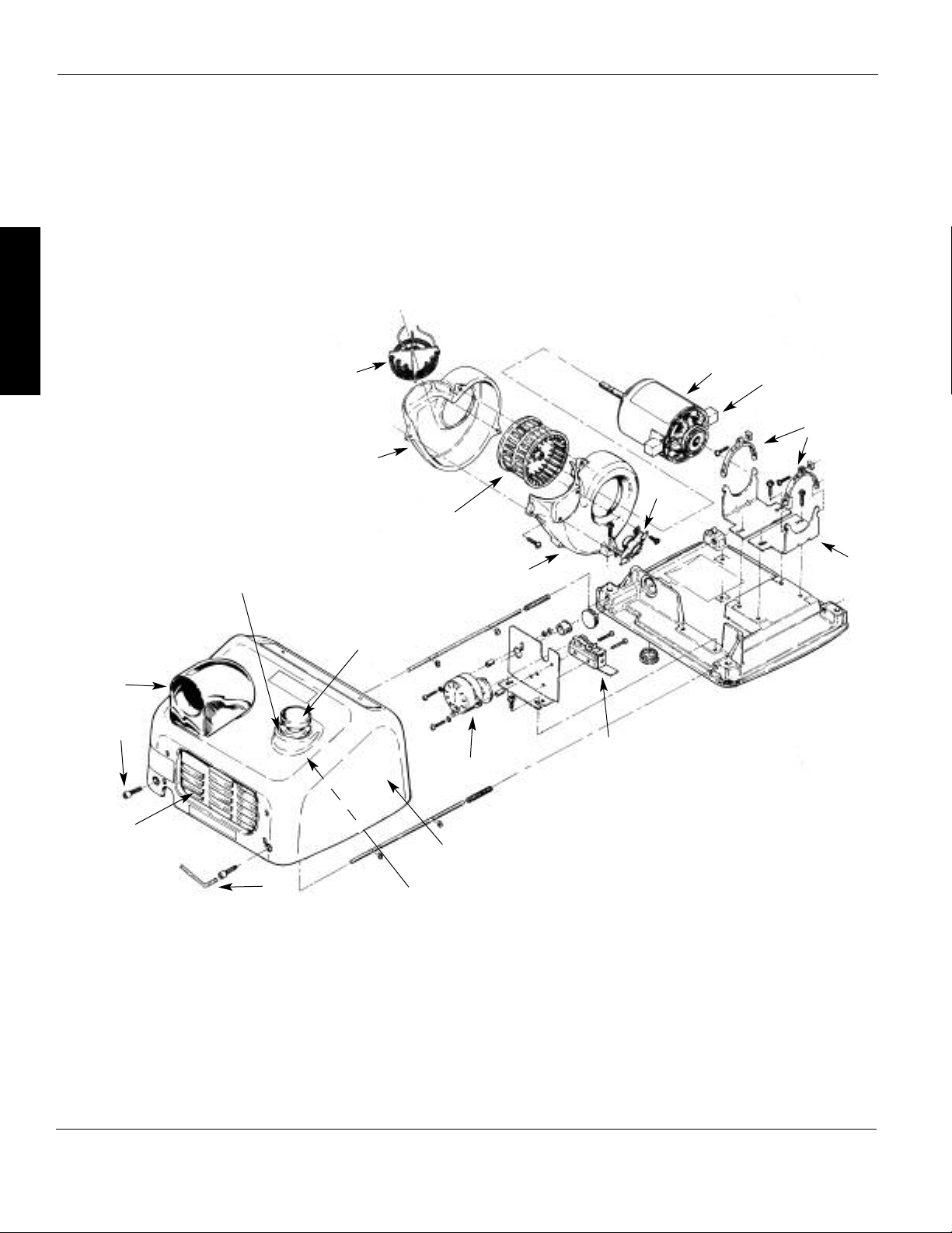
For Repair Parts, call 1 (708) 449-0701
Please provide following information:
-Model number
-Serial number
-Part description and number as shown in parts list
E
N
G
L
I
S
H
18
17
16
19
(D)XA and (D)A
1
2
3
13
14
12
11
10
9
Figure 1 – Repair Parts Illustration for Warm Air Hand Dryers
8
15
4
5
6
7
4
Page 5
World Dryer Operating Instructions and Parts Manual
R
Models (D)XA and (D)A
Repair Parts List for Warm Air Hand Dryers
Reference
Number Description Part Number Quantity
1 Motor - 115 V (D)A5, (D)XA5, (D)A52, (D)XA52 210K 1
Motor - 208/220-240 V (D)A54, (D)XA54, (D)A548, (D)XA548, †(D)A57, †(D)XA57 210ACEK 1
2 Motor Brush 206NL 2
3 Motor Mounting Strap 110-4A 2 sets
4 Motor Mounting Brackets 110-4 2
5 Micro Switch Only (D)A(All) 143F 1
6 Switch Timer Unit - 115 V, 30 Seconds (D)A5, (D)A52 225 1
Switch Timer Unit - 208-230 V, 30 Seconds (D)A54, (D)A57 225A 1
Switch Timer Unit - 220-240 V, 50 Hz, 30 Seconds (D)A548 225M 1
7 Cover Complete, Cast Iron, Automatic, White XA(All)* 70XA5-974AK 1
Cover Complete, Cast Iron, Pushbutton, White A(All)* 70A5-974AK 1
Cover Complete, Steel, Automatic, White DXA(All)* 72DXA5-974K 1
Cover Complete, Steel, Pushbutton, White DA(All)* 72DA5-974K 1
Cover Complete, Stainless Steel, Auto/Pushbutton* Call to order 1
8 Pushbutton Retaining Ring, Insulated Push Rod Tip, and Spring Kit (D)A(All) 193K 1
9 Security Allen Wrench 204TP 1
10 Inlet Grill, Cast Iron, Pushbutton, with Mtg. Hardware A(All) 194-1K 1
Inlet Grill, Cast Iron, Automatic, with Mtg. Hardware XA(All) 194-1BK 1
11 Tamper Proof Cover Screw, Cast Iron Covers 100B2 2
Tamper Proof Cover Screw, Steel Covers 46-330 2
Lock Washer, Steel Covers 59-005028 2
12 Nozzle Assembly Kit 34-172K 1
13 Pushbutton Adapter, Gasket and Bushing Unit (D)A(All) 190K 1
14 Pushbutton Assembly Kit (Knob, Rod, Ring, Spring and Tip) (D)A(All) 185K 1
15 Blower Scroll Half with Base Mount and Thermostat 211PA 1
16 Blower Plastic 101P 1
17 Blower Scroll Half with Terminal Block - Left Side 112P 1
18
19
∆ Automatic Sensor Control - 115 V (D)XA 16-230-120 (D)A
∆ Automatic Sensor Control - 208-230 V (D)XA54
∆ Automatic Sensor Control - 220-240 V, 50Hz CE
∆ Infrared Sensor, Eye (D)XA(All)
Heating Element - 115 V, 20 AMP (D)A5, (D)XA5 213K 1
Heating Element - 115 V, 15 AMP (D)A52, (D)XA52 213B
Heating Element - 230 V (D)A54, (D)XA54, (D)A548, (D)XA548 213A4K
Heating Element - 277 V, 8.5 AMP (D)A57, (D)XA57
Thermostat Only 3/4”
Only (D)XA548
213A7 1
1111-03 1
16-240-208 (D)A 1
16-230-240 CE 1
49-238 1
1
1
1
E
N
G
L
I
S
H
Specify model when ordering.
(*)
277 Volt Models Use 210ACEK Motor (230 V Power Tap).
(†)
Not shown.
(∆)
5
Page 6
orld Dryer Operating Instructions and Parts Manual
R
W
(D)XA and (D)A
World Dryer™Warm Air Hand Dryers
E
N
G
Troubleshooting Chart
L
Symptom Possible Cause(s) Corrective Action
I
Dryer fails to start
S
H
A glow is seen through
nozzle but no air is blowing
Dryer blows cold air
Automatic model dryer
will not shut off
No power to unit
Defective motor
Defective heating element
or defective thermostat
Sensor is dirty, defective
or there is a reflection
Check power to unit and connections
Replace motor brushes or motor if bad
Disconnect the unit from the electrical supply and remove
the cover. Check the heating element and thermostat with
a universal meter and replace if necessary
1. Check infra-red eye for dirt or damage. Use plastic lenses
cleaning solution and a soft cloth. Dry lens with a soft cloth
2. Make sure that sensor is not getting a reflection from
another object
3. Test relay/contactor for coil continuity using an ohm meter.
Coil resistance should not exceed 2000 ohms
4. After electricity has been applied to the dryer, it should
turn on within a few seconds. Test by placing hands
3 to 6 inches below the nozzle
LIMITED WARRANTY
WORLD TEN-YEAR LIMITED WARRANTY. WORLD DRYER™WARM AIR HAND DRYERS, MODELS COVERED IN THIS MANUAL, ARE WARRANTED BY
DRYER CORP. TO THE ORIGINAL USER AGAINST DEFECTS IN WORKMANSHIP OR MATERIALS UNDER NORMAL USE FOR TEN YEARS AFTER
WORLD
DATE OF PURCHASE. ANY PART WHICH IS DETERMINED TO BE DEFECTIVE IN MATERIAL OR WORKMANSHIP AND RETURNED, SHIPPING COSTS PREPAID,
WILL BE, AS THE EXCLUSIVE REMEDY, REPAIRED OR REPLACED AT WORLD’S OPTION. FOR LIMITED WARRANTY CLAIM PROCEDURES, SEE “PROMPT
DISPOSITION” BELOW. THIS LIMITED WARRANTY GIVES PURCHASERS SPECIFIC LEGAL RIGHTS WHICH VARY FROM JURISDICTION TO JURISDICTION.
LIMITATION OF LIABILITY. TO THE EXTENT ALLOWABLE UNDER APPLICABLE LAW, WORLD’S LIABILITY FOR CONSEQUENTIAL AND INCIDENTAL
DAMAGES IS EXPRESSLY DISCLAIMED. WORLD’S LIABILITY IN ALL EVENTS IS LIMITED TO AND SHALL NOT EXCEED THE PURCHASE PRICE PAID.
WARRANTY DISCLAIMER. A DILIGENT EFFORT HAS BEEN MADE TO PROVIDE PRODUCT INFORMATION AND ILLUSTRATE THE PRODUCTS IN THIS
LITERATURE ACCURATELY; HOWEVER, SUCH INFORMATION AND ILLUSTRATIONS ARE FOR THE SOLE PURPOSE OF IDENTIFICATION, AND DO NOT
EXPRESS OR IMPLY A WARRANTY THAT THE PRODUCTS ARE MERCHANTABLE, OR FIT FOR A PARTICULAR PURPOSE, OR THAT THE PRODUCTS WILL
NECESSARILY CONFORM TO THE ILLUSTRATIONS OR DESCRIPTIONS. EXCEPT AS PROVIDED BELOW, NO WARRANTY OR AFFIRMATION OF FACT,
EXPRESSED OR IMPLIED, OTHER THAN AS STATED IN THE “LIMITED WARRANTY” ABOVE IS MADE OR AUTHORIZED BY WORLD.
Technical Advice and Recommendations, Disclaimer. Notwithstanding any past practice or dealings or trade custom, sales shall not include
the furnishing of technical advice or assistance or system design. World assumes no obligations or liability on account of any unauthorized
recommendations, opinions or advice as to the choice, installation or use of products.
Product Suitability. Many jurisdictions have codes and regulations governing sales, construction, installation, and/or use of products for certain
purposes, which may vary from those in neighboring areas. While attempts are made to assure that World products comply with such codes, World
cannot guarantee compliance, and cannot be responsible for how the product is installed or used. Before purchase and use of a product, review the
product applications, and all applicable national and local codes and regulations, and be sure that the product, installation, and use will comply
with them.
Certain aspects of disclaimers are not applicable to consumer products; e.g., (a) some jurisdictions do not allow the exclusion or limitation of incidental
or consequential damages, so the above limitation or exclusion may not apply to you; (b) also, some jurisdictions do not allow a limitation on how
long an implied warranty lasts, consequently the above limitation may not apply to you; and (c) by law, during the period of this Limited Warranty,
any implied warranties of implied merchantability or fitness for a particular purpose applicable to consumer products purchased by consumers,
may not be excluded or otherwise disclaimed.
Prompt Disposition. A good faith effort will be made for prompt correction or other adjustment with respect to any product which proves to be
defective within limited warranty. For any product believed to be defective within limited warranty, first write or call dealer from whom the product
was purchased. Dealer will give additional directions. If unable to resolve satisfactorily, write to World at address below, giving dealer’s name, address,
date, and number of dealer’s invoice, and describing the nature of the defect. Title and risk of loss pass to buyer on delivery to common carrier.
If product was damaged in transit to you, file claim with carrier.
Manufactured by World Dryer Corp.
Berkeley, Illinois 60163 U.S.A.
Page 7
Manual de Instrucciones de Operación y Lista de Partes (D)XA y (D)A
R
Por favor lea y guarde estas instrucciones. Léalas cuidadosamente antes de tratar de montar, instalar, operar o dar mantenimiento al producto
aquí descrito. Protéjase usted mismo y a los demás observando toda la información de seguridad. ¡El no cumplir con las instrucciones puede
casionar daños, tanto personales como a la propiedad! Guarde estas instrucciones para referencia en el futuro.
o
Secamanos por aire
™
caliente World Dryer
Descripción
El Secamanos por aire caliente World Dryer, impulsado por un motor universal con
escobillas, suministra 2300 vatios de potencia de secado. Este secamanos funciona
con un suministro eléctrico de 115 voltios de CA o 208/220-240 voltios de CA,
dependiendo del modelo. Este grupo de productos incluye modelos automáticos
y de activación por botón pulsador. Los mismos han sido diseñados para uso como
secadores de manos, lo cual contribuye a una limpieza higiénica y costo-efectiva
de las manos. Este secamanos se puede usar en entornos comerciales, industriales,
de oficinas e instalaciones públicas.
Especificaciones Generales
Modelo Boquilla de secado (A x Alt. x P) (kg) la cubierta
(D)XA Fija Automático 289 x 244 x 206 mm 8,2/13,2 Acero/Hierro
(D)A Universal* 30 segundos 289 x 244 x 206 mm 8,2/13,2 Acero/Hierro
(*) La boquilla universal se puede convertir en campo a una configuración giratoria.
Tiempo Dimensiones Peso Material de
Especificaciones Eléctricas (Clasificación cULus, E19860, CE TUV-GS)
Modelo Tipo Entrada eléctrica Amperaje Vatios
(D)XA5 Automático 115 VCA / 60 Hz 20 2300
(D)A5 Botón pulsador 115 VCA / 60 Hz 20 2300
(D)XA52 Automático 115 VCA / 60 Hz 15 1725
(D)A52 Botón pulsador 115 VCA / 60 Hz 15 1725
(D)XA54 Automático 208-230 VCA / 60 Hz 10 2300
(D)A54 Botón pulsador 208-230 VCA / 60 Hz 10 2300
(D)XA548 Automático 220-240 VCA / 50 Hz 10 2300
(D)A548 Botón pulsador 220-240 VCA / 50 Hz 10 2300
(D)XA57
(D)A57
Desembalaje
1. Retire todos los materiales de embalaje. Se recomienda reciclar los
materiales.
Automático 277 VCA / 60 Hz 8,5 2300
Botón pulsador 277 VCA / 60 Hz 8,5 2300
2. Extraiga cuidadosamente el secamanos de la caja de envío, sin dejar
caer el aparato.
3. Inspeccione el producto cuidadosamente para verificar si se han pro-
ducido daños durante el transporte.
Revise para verificar si hay partes
sueltas, que faltan o que están
dañadas. Si el secamanos está dañado,
infórmele prontamente sobre dicho
daño al consignador o al concesionario de quien compró el secamanos.
Información de Seguridad
General
No desconectar la
fuente de alimentación eléctrica antes de realizar la
instalación, puede resultar en lesiones
graves o la muerte debido a un choque
eléctrico.
– Siempre desconecte la fuente de
energía antes de instalar el secamanos o darle mantenimiento al mismo.
No conectar
correctamente
a tierra esta unidad puede resultar
en un choque eléctrico grave y/o
la muerte.
– Este secamanos se debe conectar
correctamente a tierra (unida a tierra)
para que funcione en forma segura.
En el chasis del secamanos se
suministra un punto de conexión
a tierra identificado.
– Aunque el Código Eléctrico Nacional
(NEC, por sus siglas en inglés) estadounidense no lo exige, nosotros
recomendamos utilizar una protección
GFCI (interruptor de circuito de fallo a
tierra) en los lugares mojados o húmedos o donde lo exija el código local.
E
S
P
A
Ñ
O
L
Secamanos cm (pulg.) Secador de cabello cm (pulg.)
Baños de hombres 117 (46) Vestidores de hombres 173 (68)
Baños de mujeres 112 (44) Vestidores de mujeres 150 (59)
Baños de niños, edades de 4 a 7 81 (32) Vestidores de niños, edades de 4 a 7 104 (41)
Baños de niños, edades de 7 a 10 91 (36) Vestidores de niños, edades de 7 a 10 122 (48)
Baños de niños, edades de 10 a 13 102 (40) Vestidores de niños, edades de 10 a 13 137 (54)
Baños de niños, edades de 13 a 17 112 (44) Vestidores de niños, edades de 13 a 17 150 (59)
Altura de montaje para discapacitados 94 (37) Altura de montaje para discapacitados 140 (55)
Tabla 1
Formulario 68-080709 Rev 8/07/09
Alturas de montaje recomendadas desde el suelo hasta el lado inferior del secamanos
Impreso en China
Page 8

anual de Instrucciones de Operación y Lista de Partes World Dryer
M
Secamanos por aire caliente
™
World Dryer
(D)XA y (D)A
Información de Seguridad
General (Continuación)
Los siguientes:
riesgo de incendio,
lesiones personales o daño a la propiedad son posibles si no se cumple con
los códigos locales, el código eléctrico
nacional (NEC) estadounidense o las
recomendaciones de seguridad.
– Utilice únicamente la energía
eléctrica (voltaje y frecuencia)
especificada para el modelo de
secamanos que se esté instalando.
– Conecte el secamanos en el panel
E
S
P
A
Ñ
O
L
de distribución adecuado más cercano.
– Para limitar las caídas de voltaje,
y garantizar un funcionamiento
eficiente, utilice un conductor de
tamaño número 12 o más grande
de acuerdo con los requisitos de
su localidad o del código eléctrico
nacional estadounidense.
– No conecte la unidad en un circuito
ramal con protección de un cortacircuito o fusible de más de 20
amperios. Esto es de acuerdo con la
norma #210-20 del Código Eléctrico
Nacional estadounidense.
– Todos los modelos automáticos de
secamanos deben tener un circuito
dedicado de 20 amperios para satisfacer los requisitos de Underwriters
Laboratories, Inc. (UL).
– Encamine todo el cableado realizado
durante la instalación lejos de todas las
partes móviles dentro del secamanos.
El montaje
incorrecto de este
secamanos puede ocasionar lesiones
personales o daño a la propiedad.
– Siga las recomendaciones de montaje
en la Tabla 1.
AVISO: Cuando se utilice cableado para montaje en superficies, se debe pedir el accesorio de desplazamiento disponible
número 100BR para adaptar el cableado a la tubería metálica eléctrica (EMT, por sus siglas en inglés) de 1/2 pulg.
Tipo de pared
Baldosa hueca, malla, pared de yeso o metal
Cemento, ladrillo, o cemento o ladrillo
recubierto con baldosas
Pared soportada con postes con respaldo
de madera
Tabla 2
– En una pared con postes de soporte,
se debe montar un lado del secamanos en un poste existente.
Instalación
PARA LOS MODELOS (D)A5, 52, 54,
548, 57
. Desconecte la fuente de alimentación.
1
2. Utilice la llave Allen de seguridad
suministrada para extraer los (2)
tornillos de montaje de la cubierta.
Retire la cubierta del secador.
3. Coloque la base del secamanos en
el lugar deseado en la pared usando
la Tabla 1 para determinar la altura
de montaje recomendada. Con la
base ya situada, utilícela como una
plantilla para marcar los lugares de
los 4 orificios en la pared para los
pernos de montaje. Cuando se instalan
dos o más secadores, estos deben
separarse 61 cm (24 pulg.) como
mínimo de centro a centro.
4. Fije la base en la pared, usando el
tipo de pernos sugerido en la Tabla 2.
5. Conecte el secador en el panel de
distribución adecuado más cercano.
6. Monte la cubierta, y asegúrese de
no apretar demasiado los pernos.
PARA LOS MODELOS DE SECADOR
AUTOMÁTICOS (D)XA5, 52, 54, 548, 57
1. Desconecte la fuente de alimentación.
2. Utilice la llave Allen de seguridad
suministrada para extraer los (2)
tornillos de montaje de la cubierta.
Retire la cubierta del secador.
3. Coloque la base del secamanos en
el lugar deseado en la pared usando
la Tabla 1 para determinar la altura
de montaje recomendada. Con la
base ya situada, utilícela como una
plantilla para marcar los lugares de los
Tipo de perno
Tornillo tipo (M6) de 1/4 pulg. o pernos
acodados de tipo mariposa
Pernos de expansión de tipo para
postes (M6) de 1/4 pulg.
Tornillos para madera (M8) número 16
4 orificios en la pared para los pernos
de montaje. Cuando se instalan dos o
más secadores, estos deben separarse
61 cm (24 pulg.) como mínimo de
centro a centro. Sólo aplica a los
modelos automáticos: asegúrese que
o haya ningún objeto reflexivo (tal
n
como un lavabo) situado directamente
debajo del ojo sensor infrarrojo; la
distancia mínima es 46 cm (18 pulg).
4. Todos los secadores automáticos
deben tener su propio circuito
dedicado de 20 amperios según
el requisito de UL.
IMPORTANTE: Consulte los reglamentos
locales y generales antes de realizar la
instalación del secador. Asegúrese que
la red eléctrica no esté sobrecargada.
No conecte la unidad en un circuito
ramal de más de 20 amperios.
Mantenimiento
1. Extraiga el fusible o corte la alimentación eléctrica para el secador en la
caja de fusibles.
2. Con la llave Allen de seguridad
suministrada con el secador, extraiga
dos tornillos Allen del lado inferior
de la caja del secador.
3. Retire la cubierta del secador.
INSTRUCCIONES DE LIMPIEZA
Lea todas las instrucciones antes de
proceder. Bajo uso normal, la limpieza
del Secador una vez al año lo mantendrá
en buena condición de funcionamiento.
Si el tráfico en el baño es más pesado
que lo normal, la limpieza debe realizarse cada 6 meses. Las acumulaciones
de pelusas y polvo dentro del secador
pueden dañar el motor y el elemento
calentador, y también pueden producir
emisiones calientes que podrían
lesionar a los usuarios.
Longitud mínima del perno
Depende del grosor de la pared
76 mm (3 pulg.)
70 mm (23/4 pulg.)
2-Es
Page 9

Manual de Instrucciones de Operación y Lista de Partes World Dryer
R
Modelos (D)XA y (D)A
Mantenimiento
(Continuación)
1. Apague el secador en el panel de
fusibles o del cortacircuito.
2. Extraiga dos tornillos de montaje
de la cubierta del secador usando la
llave Allen de seguridad suministrada.
Sujete la cubierta mientras extrae
los tornillos.
3. Extraiga tres (3) tornillos laterales que
sujetan la carcasa del soplador. Observe
la posición del elemento calentador.
Los conductores de acometida están
orientados hacia el agujero de alivio
en las mitades de la carcasa del
soplador. Retire cuidadosamente el
elemento calentador; sin embargo,
no desconecte los conductores.
4. Limpie las mitades de la rueda del
soplador usando un cepillo cilíndrico
de cerdas radiales de 12,7 mm (1/2
pulg.) de diámetro. Inserte el cepillo
en los espacios entre las paletas
individuales y desaloje la suciedad.
No doble las paletas.
5. Aspire la suciedad del secador y la
carcasa, vuelva a colocar el elemento
calentador y la mitad de la carcasa y
reinstale los tres (3) tornillos laterales.
Apriete ligeramente y asegúrese que
las piezas del elemento calentador
de mica estén situadas en las ranuras
de la carcasa y los conductores de
conexión pasen a través del agujero
en la carcasa del soplador.
6. Use una brocha para pintar de cerdas
medio-suave de 12,7 mm (1/2 pulg.)
para limpiar el polvo y la suciedad
del motor y del temporizador
interruptor. No doble las paletas del
interruptor cuando limpie el mismo.
Utilice un cepillo de cerdas firmes
7.
para limpiar la suciedad del interior
de la rejilla de la boquilla y de la
rejilla de entrada. Quizá se necesite
agua para purgar la suciedad de la
rejilla de entrada. Si se utiliza agua,
seque el interior de la cubierta antes
de volverla a montar.
8. Inspeccione las escobillas del motor.
Para inspeccionar las escobillas,
inserte un palillo de dientes en el
agujero en el extremo del conjunto
de la escobillas. Si puede insertar el
palillo de dientes más de 2,5 cm,
reemplace las escobillas. (Consulte
las instrucciones de reemplazo).
9. Vuelva a instalar la cubierta. Coloque
la cubierta encuadrada sobre la
base y presiónela hasta que esté al
ras contra la pared. Inserte dos (2)
tornillos de montaje de la cubierta y
apriételos hasta que estén ajustados.
No los apriete demasiado.
REEMPLAZO DE LAS ESCOBILLAS
DEL MOTOR
1. Retire la presilla de resorte de fijación
que sujeta el portaescobillas.
2. Saque lentamente la tapa de la
escobilla fuera del motor hasta que
aparezca el conector del conductor.
3. Desconecte el conector del conductor
y retire el conjunto del portaescobilla
y la escobilla.
AVISO: Cuando desembale el conjunto
de las escobillas de la caja de envío,
es importante mantener firmemente
sujetada la escobilla de carbón en
el portaescobillas. P/N 206NL
4. Inserte el conjunto nuevo en el punto
donde se pueda hacer la conexión
rápida del conductor.
5. Conecte a presión los manguitos
de las escobillas en los conectores
rápidos para escobillas en el motor.
6. Vuelva a colocar el conjunto de las
escobillas en su lugar e inserte la
presilla de resorte de fijación.
REEMPLAZO DEL ELEMENTO
CALENTADOR
1. Extraiga los tres tornillos que sujetan
la carcasa del soplador (número 211PA
y número 112P), y retire el lado
número 112P de la carcasa.
Desconecte los conductores blancos
2.
del elemento calentador en el bloque
de terminales y de las terminales
del interruptor. Instale el nuevo
elemento calentador con tensión
y vataje correctos, observando la
misma conexión que se utilizó con
el elemento calentador antiguo.
3. Sujete el elemento en posición en
el lado estacionario de la carcasa del
soplador y deslice el lado desmontable
en su lugar, asegurándose que las
estructuras del elemento encajen en
las ranuras en la carcasa del soplador
y ambos conductores pasen a través
de la muesca en la parte superior de
la salida de aire, y reinstale los tres
tornillos que sujetan la carcasa del
soplador.
4. Vuelva a conectar los conductores en
el bloque de terminales y el interruptor. Consulte el diagrama de cableado
en la cubierta. Asegúrese de volver
a conectar debidamente todos los
conductores, prestando atención al
diagrama de cableado dentro de
la cubierta del secador.
REEMPLAZO DEL TEMPORIZADOR
INTERRUPTOR EN LOS MODELOS
(D)A5, 52, 54, 548, 57
1. Extraiga los tornillos de cada una de
las dos terminales en el temporizador
interruptor, y marque los conductores
para poder volverlos a conectar
correctamente en las terminales
del interruptor.
2. Reemplace el temporizador defectuoso con uno nuevo. (Especifique
el Modelo de Secador cuando pida
el Temporizador).
3. Vuelva a conectar los conductores
en las terminales.
4. Vuelva a instalar la cubierta
(asegurándose que la cubierta encaje
perfectamente sobre la unidad base)
y presiónela hacia adentro hasta que
la cubierta esté al ras con la pared e
inserte los dos tornillos de montaje
de la cubierta. No apriete demasiado
los tornillos de montaje.
Conecte la alimentación eléctrica
5.
para el secador.
E
S
P
A
Ñ
O
L
3-Es
Page 10

anual de Instrucciones de Operación y Lista de Partes World Dryer
M
(D)XA y (D)A
Para Obtener Partes de Reparación llame al 1 (708) 449-0701
Por favor proporciónenos la siguiente información:
-Número de modelo
-Número de serie (si lo tiene)
-Descripción de la parte y número que le corresponde en la lista de partes
18
E
S
17
1
2
3
P
A
Ñ
16
19
O
L
15
4
13
14
12
11
5
6
10
7
9
Figura 1 – Ilustración de las Partes de Reparación para los Secamanos por Aire Caliente
8
4-Es
Page 11

Manual de Instrucciones de Operación y Lista de Partes World Dryer
R
Modelos (D)XA y (D)A
Lista de Partes de Reparación para los Secamanos por Aire Caliente
No. de No. de
Ref. Descripción Parte Cant.
1 Motor - 115 V (D)A5, (D)XA5, (D)A52, (D)XA52 210K 1
Motor - 208/220-240 V (D)A54, (D)XA54, (D)A548, (D)XA548, †(D)A57, †(D)XA57 210ACEK 1
2 Escobilla del motor 206NL 2
3 Abrazadera de montaje del motor 110-4A 2 juegos
4 Piezas de soporte de montaje del motor 110-4 2
5 Micro interruptor sólo (D)A(todos) 143F 1
6 Unidad de temporizador interruptor - 115 V, 30 segundos (D)A5, (D)A52 225 1
Unidad de temporizador interruptor - 208-230 V, 30 segundos (D)A54, (D)A57 225A 1
Unidad de temporizador interruptor - 220-240 V, 50 Hz, 30 segundos (D)A548 225M 1
7 Cubierta completa, hierro fundido, automático, blanco XA(todos)* 70XA5-974AK 1
Cubierta completa, hierro fundido, botón pulsador, blanco A(todos)* 70A5-974AK 1
Cubierta completa, acero, automático, blanco DXA(todos)* 72DXA5-974K 1
Cubierta completa, acero, botón pulsador, blanco DA(todos)* 72DA5-974K 1
Cubierta completa, acero inoxidable, automático/botón pulsador* Llame para pedirlo 1
8 Juego de anillo de retención, punta de empuje aislada y resorte 193K 1
para botón pulsador (D)A(todos)
9 Llave Allen de seguridad 204TP 1
10 Rejilla de entrada, hierro fundido, botón pulsador, con herrajes de montaje A(todos) 194-1K 1
Rejilla de entrada, hierro fundido, automático, con herrajes de montaje XA(todos) 194-1BK 1
11 Tornillo resistente a manipulaciones para la cubierta, cubiertas de hierro fundido 100B2 2
Tornillo resistente a manipulaciones para la cubierta, cubiertas de acero 46-330 2
Arandela de seguridad, cubiertas de acero 59-005028 2
12 Juego del conjunto de la boquilla 34-172K 1
13 Unidad de adaptador de botón pulsador, empaquetadura y buje (D)A(todos) 190K 1
14 Juego del conjunto del botón pulsador 185K 1
(perilla, varilla, anillo, resorte y punta), (D)A(todos)
15 Mitad de la voluta del soplador con montaje en la base y termostato 211PA 1
16 Soplador de plástico 101P 1
17 Mitad izquierda de la voluta del soplador con bloque de terminales 112P 1
18 Elemento calentador - 115 V, 20 AMP (D)A5, (D)XA5 213K 1
Elemento calentador - 115 V, 15 AMP (D)A52, (D)XA52 213B 1
Elemento calentador - 230 V (D)A54, (D)XA54, (D)A548, (D)XA548 213A4K 1
Elemento calentador - 277 V, 8,5 AMP (D)A57, (D)XA57 213A7 1
19 Termostato, sólo 3/4 pulg. 1111-03 1
∆ Control automático por sensor - 115 V (D)XA 16-230-120 (D)A 1
∆ Control automático por sensor - 208-230 V (D)XA54 16-240-208 (D)A 1
∆ Control automático por sensor - 220-240 V, 50Hz CE solamente (D)XA548 16-230-240 CE 1
∆ Sensor infrarrojo, ojo (D)XA(todos) 49-238 1
E
S
P
A
Ñ
O
L
(*) Especifique el modelo en su pedido.
(†) Modelos de 277 voltios utilizan el Motor 210ACEK (conexión de alimentación de 230 V).
(∆) No se muestra.
5-Es
Page 12

anual de Instrucciones de Operación y Lista de Partes World Dryer
R
M
Secamanos por aire caliente
™
World Dryer
Tabla de Identificación de Problemas
Síntoma Causa(s) Posible(s) Medida Correctiva
(D)XA y (D)A
El secador no arranca
La unidad no recibe
Verifique el suministro eléctrico para la unidad y las conexiones
alimentación eléctrica
Se ve un resplandor a
Motor defectuoso
Reemplace las escobillas del motor o el motor si están en mala condición
través de la boquilla
pero no sale aire
El secador sopla aire frío
El modelo de secador
automático no se apaga
E
S
P
A
Ñ
O
L
Elemento calentador
defectuoso o termostato
defectuoso
El sensor está sucio,
defectuoso o hay
una reflexión
Desconecte la unidad del circuito de suministro eléctrico y retire la
cubierta. Verifique el elemento calentador y el termostato con un
medidor universal y reemplácelos si es necesario
1. Revise el ojo infrarrojo para ver si está sucio o dañado. Utilice una
solución de limpieza para lentes de plástico y un paño suave. Seque
el lente con un paño suave
2. Asegúrese que el sensor no esté recibiendo una reflexión de otro
objeto
3. Compruebe el relé/contactor con un medidor de ohmios para verificar
la continuidad de la bobina. La resistencia de la bobina no deberá
ser superior a 2000 ohmios
4. Después de conectar la alimentación eléctrica para el secador, éste
debe encenderse al cabo de unos cuantos segundos. Coloque las
manos a una distancia de 7,5 a 15 cm por debajo de la boquilla
de salida de aire del secador para comprobar si la unidad funciona
GARANTÍA LIMITADA
GARANTÍA LIMITADA DE DIEZ AÑOS DE WORLD. WORLD DRYER CORP. LE GARANTIZA AL USUARIO ORIGINAL QUE LOS MODELOS TRATADOS
EN ESTE MANUAL DE LOS SECAMANOS POR AIRE CALIENTE WORLD DRYER™ ESTARÁN LIBRES DE DEFECTOS EN LA MANO DE OBRA O EL MATERIAL,
CUANDO SE LES SOMETE A USO NORMAL, POR DIEZ AÑOS A PARTIR DE LA FECHA DE COMPRA. CUALQUIER PARTE QUE SE HALLE DEFECTUOSA,
YA SEA EN EL MATERIAL O EN LA MANO DE OBRA, Y SEA DEVUELTA, CON LOS COSTOS DE ENVÍO PAGADOS POR ADELANTADO, SERÁ REPARADA
O REEMPLAZADA A LA DISCRECIÓN DE WORLD COMO REMEDIO EXCLUSIVO. PARA OBTENER INFORMACIÓN SOBRE LOS PROCEDIMIENTOS DE
RECLAMO CUBIERTOS EN LA GARANTÍA LIMITADA, VEA LA SECCIÓN “ATENCIÓN OPORTUNA” QUE APARECE MÁS ADELANTE. ESTA GARANTÍA
LIMITADA CONFIERE AL COMPRADOR DERECHOS LEGALES ESPECÍFICOS QUE VARÍAN DE JURISDICCIÓN A JURISDICCIÓN.
LÍMITES DE RESPONSABILIDAD. EN LA MEDIDA EN QUE LAS LEYES APLICABLES LO PERMITAN, LA RESPONSABILIDAD DE WORLD POR LOS DAÑOS
EMERGENTES O INCIDENTALES ESTÁ EXPRESAMENTE EXCLUIDA. LA RESPONSABILIDAD DE WORLD EXPRESAMENTE ESTÁ LIMITADA Y NO PUEDE
EXCEDER EL PRECIO DE COMPRA PAGADO POR EL ARTÍCULO.
EXCLUSIÓN DE RESPONSABILIDAD DE LA GARANTÍA. WORLD SE HA ESFORZADO DILIGENTEMENTE PARA PROPORCIONAR INFORMACIÓN E
ILUSTRACIONES APROPIADAS SOBRE EL PRODUCTO EN ESTE MANUAL; SIN EMBARGO, ESTA INFORMACIÓN Y LAS ILUSTRACIONES TIENEN COMO ÚNICO
PROPÓSITO LA IDENTIFICACIÓN DEL PRODUCTO Y NO EXPRESAN NI IMPLICAN GARANTÍA DE QUE LOS PRODUCTOS SEAN VENDIBLES O ADECUADOS
PARA UN PROPÓSITO EN PARTICULAR NI QUE SE AJUSTAN NECESARIAMENTE A LAS ILUSTRACIONES O DESCRIPCIONES. CON EXCEPCIÓN DE LO QUE SE
ESTABLECE A CONTINUACIÓN, WORLD NO HACE NI AUTORIZA NINGUNA GARANTÍA O AFIRMACIÓN DE HECHO, EXPRESA O IMPLÍCITA, QUE NO SEA
ESTIPULADA EN LA “GARANTÍA LIMITADA” ANTERIOR.
Consejo Técnico y Recomendaciones, Exclusiones de Responsabilidad. A pesar de las prácticas, negociaciones o usos comerciales realizados
previamente, las ventas no deberán incluir el suministro de consejo técnico o asistencia o diseño del sistema. World no asume ninguna obligación o
responsabilidad por recomendaciones, opiniones o consejos no autorizados sobre la elección, instalación o uso de los productos.
Adaptación del Producto. Muchas jurisdicciones tienen códigos o regulaciones sobre la venta, el diseño, la instalación y/o el uso de productos
para ciertas aplicaciones; dichas leyes pueden variar de un área a otra. Si bien se trata de que los productos World cumplan con dichos códigos, World
no puede garantizar su conformidad y no se puede hacer responsable por la forma en que se instale o use su producto. Antes de comprar y usar el
producto, revise sus aplicaciones y todos los códigos y regulaciones nacionales y locales aplicables y asegúrese de que el producto, la instalación y
el uso los cumplan.
Ciertos aspectos de limitación de responsabilidad no se aplican a productos al consumidor; es decir (a) algunas jurisdicciones no permiten la exclusión
ni limitación de daños incidentales o consecuentes, de modo que las limitaciones o exclusiones anteriores quizás no apliquen en su caso; (b) asimismo,
algunas jurisdicciones no permiten limitar el plazo de una garantía implícita, por lo tanto, la limitación anterior quizás no aplique en su caso; y (c) por
ley, mientras la Garantía Limitada esté vigente no podrán excluirse ni limitarse en modo alguno ninguna garantía implícita de comercialización o de
idoneidad para un propósito en particular aplicables a los productos al consumidor adquiridos por éste.
Atención Oportuna. Se hará un esfuerzo de buena fe para corregir puntualmente, o hacer otros ajustes, con respecto a cualquier producto que resulte
defectuoso dentro de los términos de esta garantía limitada. En el caso de que encuentre un producto defectuoso y que esté cubierto dentro de los
límites de esta garantía haga el favor de escribir primero, o llame, al distribuidor a quien le compró el producto. El distribuidor le dará las instrucciones
adicionales. Si no puede resolver el problema en forma satisfactoria, escriba a World a la dirección a continuación, dando el nombre del distribuidor,
su dirección, la fecha y el número de la factura del distribuidor y describa la naturaleza del defecto.
Fabricado por World Dryer Corp.
Berkeley, Illinois 60163 EE.UU.
Page 13

Manuel d’utilisation et de pièces détachées (D)XA et (D)A
R
ire et conserver ces instructions. Il faut les lire attentivement avant de commencer à assembler, installer, faire fonctionner ou entretenir
L
l’appareil décrit. Pour se protéger et protéger autrui, observer toutes les informations sur la sécurité. Négliger d’appliquer ces instructions
peut causer des blessures corporelles et/ou des dommages matériels! Conserver ces instructions pour références ultérieures.
Sèche-mains à air
™
chaud World Dryer
Description
Le sèche-mains à air chaud à moteur universel avec balais de World Dryer offre
une puissance de séchage de 2 300 watts. Ce sèche-mains fonctionne sur une
alimentation électrique alternative de 115 volts ou de 208/220-240 volts, selon
le modèle. Des modèles automatiques et à bouton-poussoir sont représentés
dans cette gamme. Ils sont conçus pour sécher les mains de façon sanitaire d’une
manière rapide, hygiénique et économique. Ce sèche-mains est conçu pour être
utilisé dans les magasins, usines, bureaux et bâtiments publics.
Caractéristiques générales
Modèle Buse séchage (La x H x Pr) (kg) du capot
(D)XA Fixe Automatique 289 x 244 x 206 mm 8,2/13,2 Acier/Fonte
(D)A Universel* 30 secondes 289 x 244 x 206 mm 8,2/13,2 Acier/Fonte
(*) La buse de type universel peut être convertie sur site pour une configuration rotative.
Cycle de Dimensions Poids Matériau
Caractéristiques électriques (Homologation cULus, E19860, CE TUV-GS)
Modèle Type Alimentation électrique Intensité Watts
(D)XA5 Automatique 115 V c.a., 60 Hz 20 2 300
(D)A5 Bouton-poussoir 115 V c.a., 60 Hz 20 2 300
(D)XA52 Automatique 115 V c.a., 60 Hz 15 1 725
(D)A52 Bouton-poussoir 115 V c.a., 60 Hz 15 1 725
(D)XA54 Automatique 208-230 V c.a., 60 Hz 10 2 300
(D)A54 Bouton-poussoir 208-230 V c.a., 60 Hz 10 2 300
(D)XA548 Automatique 220-240 V c.a., 50 Hz 10 2 300
(D)A548 Bouton-poussoir 220-240 V c.a., 50 Hz 10 2 300
(D)XA57 Automatique 277 V c.a., 60 Hz 8,5 2 300
(D)A57 Bouton-poussoir 277 V c.a., 60 Hz 8,5 2 300
Déballage
1. Enlever tous les produits d’emballage.
Il est recommandé de les recycler.
2. Enlever avec précaution le sèchemains du carton en faisant attention
de ne pas le faire tomber.
Hauteur de montage recommandée du sol au bas du sèche-mains
Sèche-mains cm (po) Sèche-cheveux cm (po)
Toilettes pour hommes 117 (46) Vestiaire pour hommes 173 (68)
Toilettes pour femmes 112 (44) Vestiaire pour femmes 150 (59)
Toilettes pour enfants de 4 à 7 ans 81 (32) Vestiaires pour enfants de 4 à 7 ans 104 (41)
Toilettes pour enfants de 7 à 10 ans 91 (36) Vestiaires pour enfants de 7 à 10 ans 122 (48)
Toilettes pour enfants de 10 à 13 ans 102 (40) Vestiaires pour enfants de 10 à 13 ans 137 (54)
Toilettes pour enfants de 13 à 17 ans 112 (44) Vestiaires pour enfants de 13 à 17 ans 150 (59)
Hauteur de montage pour handicapés 94 (37) Hauteur de montage pour handicapés 140 (55)
Tableau 1
Brochure 68-080709 Rév. 8/07/09
3. Vérifier soigneusement qu’aucun
dommage n’est survenu durant le
transport. Examiner les pièces pour
voir si certaines sont desserrées, manquantes ou endommagées. Si le sèchemains est endommagé, informer
Imprimé en Chine
immédiatement l’expéditeur ou le
concessionnaire qui vous l’a vendu.
Consignes générales de
sécurité
Le fait de négliger
de débrancher
la source d’alimentation avant de
procéder à l’installation peut entraîner
des blessures graves ou mortelles
résultant d’un choc électrique.
– Toujours débrancher la source
d’alimentation avant de réparer
ou d’installer le sèche-mains.
Veiller à mettre cet
appareil à la terre
correctement afin d’éviter un risque de
choc électrique grave, voire mortel.
– Ce sèche-mains doit être mis à la
terre correctement pour fonctionner
en toute sécurité. Un point de
raccordement à la terre est identifié
sur le châssis du sèche-mains.
– Bien que cela ne soit pas requis par
le code national de l’électricité américain, nous recommandons une protection par disjoncteur de fuite à la terre
dans les endroits mouillés ou humides,
ou lorsque le code local l’exige.
Un risque
d’incendie, de
blessures ou de dommages matériels
est possible en cas d’inobservation
des codes locaux, du code national
de l’électricité américain ou des
recommandations de sécurité.
F
R
A
N
Ç
A
I
S
Page 14

anuel d’utilisation et de pièces détachées World Dryer
M
Sèche-mains à air chaud
™
World Dryer
(D)XA et (D)A
Informations générales sur
la sécurité (suite)
– N’utiliser que le type d’alimentation
électrique (en termes de tension et de
fréquence) spécifié pour le modèle de
èche-mains en cours d’installation.
s
– Raccorder le sèche-mains au tableau
de distribution adapté le plus proche.
– Pour limiter les chutes de tension et
garantir un fonctionnement efficace,
utiliser du fil de calibre 12 ou plus
gros si le code local ou national
de l’électricité américain l’exige.
– Ne pas raccorder l’appareil à un
circuit de dérivation protégé par
un disjoncteur ou un fusible de plus
de 20 A. Cette exigence est stipulée
par l’article 210-20 du code national
de l’électricité américain.
– Pour se conformer à l’homologation
Underwriters Laboratories, Inc. (UL),
F
R
A
N
Ç
A
I
S
tous les modèles automatiques de
sèche-mains doivent être installés
sur un circuit dédié de 20 ampères.
– Faire passer l’ensemble du câblage sur
site à l’écart des pièces mobiles qui
sont à l’intérieur du sèche-mains.
Un montage
incorrect de
ce sèche-mains peut provoquer des
accidents corporels et des dommages
matériels.
– Suivre les recommandations de
montage du Tableau 1.
– Sur une cloison lattée et plâtrée,
monter un côté du sèche-mains
sur un poteau existant.
Installation
OUR LES MODÈLES (D)A5, 52, 54,
P
548, 57
1. Couper la source d’alimentation
lectrique.
é
2. Utiliser la clé mâle à six pans de
sécurité fournie pour enlever les
deux (2) vis de montage du capot.
Enlever le capot du sèche-mains.
3. Placer la base du sèche-mains sur le
mur à l’endroit désiré en consultant le
Tableau 1 pour déterminer la hauteur
de montage recommandée. La base
étant dans cette position, l’utiliser
comme gabarit pour marquer l’emplacement des 4 trous de boulons
de montage sur le mur. Lorsqu’on
installe plusieurs sèche-mains, on
doit observer une distance minimale
de séparation entre eux de 61 cm
(24 po) de centre à centre.
4. Fixer la base au mur au moyen de
boulons du type suggéré sur le
Tableau 2.
5. Brancher le sèche-mains au tableau
de distribution adapté le plus proche.
6. Remonter le capot en veillant à ne
pas serrer excessivement les boulons
de montage.
POUR LES MODÈLES AUTOMATIQUES
(D)XA5, 52, 54, 548, 57
1. Couper la source d’alimentation
électrique.
2. Utiliser la clé mâle à six pans de
sécurité fournie pour enlever les
deux (2) vis de montage du capot.
Enlever le capot du sèche-mains.
3. Placer la base du sèche-mains sur le
mur à l’endroit désiré en consultant
le Tableau 1 pour déterminer la
auteur de montage recommandée.
h
La base étant dans cette position,
l’utiliser comme gabarit pour
marquer l’emplacement des 4 trous
de boulons de montage sur le mur.
Lorsqu’on installe plusieurs sèchemains, on doit observer une distance
minimale de séparation entre eux
de 61 cm (24 po) de centre à centre.
Considération uniquement applicable
aux modèles automatiques : S’assurer
qu’aucun objet réfléchissant (tel
qu’un lavabo) ne se trouve juste en
dessous de l’œil du capteur infrarouge ;
la distance minimale est de 46 cm.
4. Tous les sèche-mains automatiques
doivent disposer de leur propre circuit
dédié de 20 A (recommandation de
l’organisme d’homologation UL).
IMPORTANT : Consulter les réglementations locale et générale avant
d’installer le sèche-mains. S’assurer que
le réseau électrique n’est pas surchargé.
Ne pas raccorder l’appareil à un circuit
de dérivation de plus de 20 A.
Entretien
1. Retirer le fusible ou mettre le sèchemains hors tension au niveau du
coffret de fusibles.
À l’aide de la clé mâle à six pans de
2.
sécurité fournie avec le sèche-mains,
dévisser les deux vis creuses du
fond du boîtier de l’appareil.
3. Enlever le capot du sèche-mains.
REMARQUE : En cas de câblage par montage en surface, le raccord coudé en option n° de pièce 100BR doit être commandé
pour le raccordement du câblage au tube électrique métallique d’alimentation de 1/2 pouce.
Type de mur
Hourdis, lattes, panneaux de revêtement
ou métal
Ciment ou brique, carrelés ou non
Cloison lattée et plâtrée avec fond bois
Tableau 2
Type de boulon
Boulons type vis (M6) ou à ailettes 1/4 po
Boulons à coquille d’expansion type
goujon (M6) 1/4 po
Vis à bois (M8) n° 16
2-Fr
Longueur minimum des boulons
Dépend de l’épaisseur du mur
76 mm (3 po)
70 mm (23/4 po)
Page 15

Manuel d’utilisation et de pièces détachées World Dryer
R
Modèles (D)XA et (D)A
Entretien (suite)
INSTRUCTIONS DE NETTOYAGE
Lire toutes les instructions avant
de procéder au nettoyage. Dans des
conditions d’utilisation normales, le
nettoyage du sèche-mains une fois
par an le maintiendra en bon état de
marche. Si la fréquentation des toilettes
est supérieure à la normale, effectuer
le nettoyage tous les 6 mois. L’accumulation de peluches et de poussières
à l’intérieur du sèche-mains peut
endommager le moteur et l’élément
de chauffage et produire des émissions
chaudes susceptibles de blesser
l’utilisateur.
1. Couper l’alimentation électrique du
sèche-mains au niveau du disjoncteur
ou du panneau de fusibles.
2. À l’aide de la clé mâle à six pans de
sécurité fournie avec le sèche-mains,
dévisser les deux vis de montage
retenant le capot. Soutenir le capot
pendant l’enlèvement des vis.
3. Enlever les trois (3) vis latérales
retenant l’ensemble du carter de
la soufflante. Noter la position de
l’élément de chauffage. Les fils conducteurs sont dirigés vers l’orifice de
dégagement dans les moitiés du carter
de la soufflante. Sans déconnecter les
fils, enlever avec précaution l’élément
de chauffage de son logement.
4. Nettoyer les moitiés de la roue de
la soufflante en utilisant une brosse
à soies radiales de 12,7 mm (1/2 po)
de diamètre. En veillant à ne pas
tordre les ailettes, brosser entre les
ailettes pour déloger les salissures.
5. Avec un aspirateur, éliminer la
poussière de la soufflante et de son
carter, remettre en place l’élément
de chauffage et sa moitié de carter,
et revisser les trois (3) vis latérales.
Serrer avec modération en veillant
à ce que les pièces en mica de
l’élément de chauffage soient
positionnées dans leur logement et
que les fils d’alimentation passent
par l’orifice du carter de la soufflante.
6. En veillant à ne pas tordre la lame
du minuteur, utiliser un pinceau à
soies souples de 12,7 mm (1/2 po) pour
dépoussiérer et décrasser le moteur
et le minuteur.
7. Utiliser une brosse dure pour nettoyer
les salissures à l’intérieur des grilles
de sortie et d’entrée d’air. Il peut
être nécessaire d’utiliser de l’eau
pour évacuer les salissures de la grille
d’entrée. En cas d’utilisation d’eau,
sécher l’intérieur du capot avant
de le remonter.
8. Inspecter les balais du moteur.
Pour cela, insérer un cure-dents dans
l’orifice à l’extrémité de l’ensemble
des balais. Si le cure-dents s’enfonce
de plus de 2,5 cm, remplacer les
balais. (Voir la rubrique Remplacement des balais du moteur.)
9. Remonter le capot en le plaçant droit
sur la base et en le poussant contre le
mur. Insérer les deux vis de montage
du capot et les serrer jusqu’à ce
qu’elles soient bien ajustées, sans
toutefois les serrer excessivement.
REMPLACEMENT DES BALAIS
DU MOTEUR
1. Enlever la pince à ressort de
verrouillage retenant le porte-balais.
2. Sortir lentement du moteur
le capuchon des balais jusqu’à
apparition du connecteur électrique.
3. Détacher le connecteur et enlever
l’ensemble des balais et du portebalais.
REMARQUE : Pendant le déballage hors
du carton d’expédition de l’ensemble
des balais, il est important de maintenir
solidement les balais en carbone dans
le porte-balais. N° de pièce 206NL
Introduire le nouvel ensemble jusqu’à
4.
la position où le raccordement des fils
par raccord rapide peut être effectué.
5. Pousser l’un contre l’autre les raccords
rapides sur le moteur et le manchon
des balais.
Remettre l’ensemble des balais dans sa
6.
position de fonctionnement et insérer
la pince à ressort de verrouillage.
REMPLACEMENT DE L’ÉLÉMENT
E CHAUFFAGE
D
1. Enlever les trois vis retenant
ensemble les éléments du carter de
la soufflante (n
112P) et enlever l’élément 112P.
2. Déconnecter les fils blancs de l’élément de chauffage sur le bornier et
le commutateur. Remplacer l’élément
de chauffage en s’assurant que la
tension et l’ampérage sont corrects,
et en veillant à le connecter d’une
manière identique à l’ancien élément.
3. Maintenir l’élément en position
sur côté stationnaire du carter de la
soufflante et glisser le côté amovible
du carter en position, en veillant à
ce que les armatures de l’élément se
placent dans les logements du carter
de la soufflante et que les deux fils
se trouvent dans le passage à la
partie supérieure de la sortie d’air.
Remonter les trois vis retenant
ensemble les éléments du carter
de la soufflante.
4. Reconnecter les fils au bornier et au
commutateur. S’assurer que tous les
fils sont correctement reconnectés et
que le câblage correspond au schéma
de câblage situé à l’intérieur du
capot du sèche-mains.
REMPLACEMENT DU MINUTEUR
POUR LES MODÈLES (D)A5, 52, 54,
548, 57
1. Enlever les vis de chacune des deux
bornes du minuteur, en marquant
les fils afin de permettre une
reconnexion correcte au moment
du remontage.
2. Remplacer le minuteur défectueux.
(Pour la commande du minuteur,
spécifier le modèle du sèche-mains.)
3. Reconnecter les fils aux bornes
du minuteur.
4. Remettre le capot en place (en
s’assurant qu’il est bien ajusté sur la
base) et le pousser contre le mur, puis
visser les deux vis de montage sans
les serrer excessivement.
5. Mettre le sèche-mains sous tension.
os
de pièce 211PA et
F
R
A
N
Ç
A
I
S
3-Fr
Page 16

anuel d’utilisation et de pièces détachées World Dryer
M
(D)XA et (D)A
Pour des pièces détachées, appeler le 1 (708) 449-0701
Fournir les informations suivantes :
-Numéro de modèle
-Numéro de série (s’il y en a un)
-Description et numéro de pièce comme indiqué sur la liste des pièces
18
1
2
3
17
19
16
15
4
13
F
R
A
14
N
Ç
12
A
I
S
11
5
6
10
7
9
Figure 1 – Illustration des pièces détachées des sèche-mains à air chaud
8
4-Fr
Page 17

Manuel d’utilisation et de pièces détachées World Dryer
R
Modèles (D)XA et (D)A
Liste des pièces détachées des sèche-mains à air chaud
N° de N° de
réf. Description pièce Qté
1 Moteur - 115 V (D)A5, (D)XA5, (D)A52, (D)XA52 210K 1
Moteur - 208/220-240 V (D)A54, (D)XA54, (D)A548, (D)XA548, †(D)A57, †(D)XA57 210ACEK 1
2 Balais du moteur 206NL 2
3 Bride de montage du moteur 110-4A 2 jeux
4 Supports de montage du moteur 110-4 2
5 Microcommutateur seulement (D)A(tous) 143F 1
6 Minuteur - 115 V, 30 secondes (D)A5, (D)A52 225 1
Minuteur - 208-230 V, 30 secondes (D)A54, (D)A57 225A 1
Minuteur - 220-240 V, 50 Hz, 30 secondes (D)A548 225M 1
7 Capot complet, fonte, automatique, blanc XA(tous)* 70XA5-974AK 1
Capot complet, fonte, bouton-poussoir, blanc A(tous)* 70A5-974AK 1
Capot complet, acier, automatique, blanc DXA(tous)* 72DXA5-974K 1
Capot complet, acier, bouton-poussoir, blanc DA(tous)* 72DA5-974K 1
Capot complet, acier inoxydable, automatique/bouton-poussoir* Appeler pour 1
commander
8 Kit de bague de retenue, embout de tige-poussoir isolé et ressort 193K 1
du bouton-poussoir (D)A(tous)
9 Clé mâle à six pans de sécurité 204TP 1
10 Grille d’entrée d’air, fonte, bouton-poussoir, avec matériel de montage A(tous) 194-1K 1
Grille d’entrée d’air, fonte, automatique, avec matériel de montage XA(tous) 194-1BK 1
11 Vis de capot inviolable, capots en fonte 100B2 2
Vis de capot inviolable, capots en acier 46-330 2
Rondelle de blocage, capots en acier 59-005028 2
12 Kit de montage de buse 34-172K 1
13 Adaptateur de bouton-poussoir, joint d’étanchéité et douille (D)A(tous) 190K 1
14 Kit de montage de bouton-poussoir 185K 1
(Bouton, tige, bague, ressort et embout) (D)A(tous)
15 Demi-volute de soufflante avec base de montage et thermostat 211PA 1
16 Soufflante en plastique 101P 1
17 Demi-volute de soufflante avec bornier - côté gauche 112P 1
18 Élément de chauffage - 115 V, 20 A (D)A5, (D)XA5 213K 1
Élément de chauffage - 115 V, 15 A (D)A52, (D)XA52 213B 1
Élément de chauffage - 230 V (D)A54, (D)XA54, (D)A548, (D)XA548 213A4K 1
Élément de chauffage - 277 V, 8,5 A (D)A57, (D)XA57 213A7 1
19 Thermostat seul, 3/4 po 1111-03 1
∆ Commande de capteur automatique - 115 V (D)XA 16-230-120 (D)A 1
∆ Commande de capteur automatique - 208-230 V (D)XA54 16-240-208 (D)A 1
∆ Commande de capteur automatique - 220-240 V, 50 Hz CE seulement (D)XA548 16-230-240 CE 1
∆ Œil du capteur infrarouge (D)XA(tous) 49-238 1
F
R
A
N
Ç
A
I
S
(*) Spécifier le modèle pour la commande.
(†) Pour les modèles 277 volts utiliser un moteur 210ACEK (prise 230 V).
(∆) Non représenté.
5-Fr
Page 18

anuel d’utilisation et de pièces détachées World Dryer
R
M
Sèche-mains à air chaud
™
World Dryer
Tableau de dépannage
Symptôme Cause(s) possible(s) Action corrective
(D)XA et (D)A
Le sèche-main ne
démarre pas
Un rougeoiement est
Le sèche-main n’est pas
alimenté électriquement
Le moteur est défectueux
Vérifier l’alimentation et les connexions de l’appareil
Remplacer les balais du moteur ou le moteur lui-même, si défaillant
visible à travers la buse,
mais aucun air n’en sort
Le sèche-mains souffle
de l’air froid
Un modèle automatique
de sèche-mains ne
s’arrête pas
L’élément de chauffage
ou le thermostat est
défectueux
Le capteur est sale
ou défectueux, ou il
reçoit une réflexion
intempestive
Débrancher l’appareil de son alimentation électrique et déposer le
capot. À l’aide d’un multimètre, vérifier l’élément de chauffage et
le thermostat, et procéder à tout remplacement nécessaire
1. Vérifier l’œil infrarouge pour voir s’il est encrassé ou endommagé.
Utiliser une solution de nettoyage de lentille en plastique et
un chiffon doux. Sécher la lentille avec un chiffon doux
2. Vérifier que le capteur ne reçoit pas une réflexion provenant
d’un autre objet
3. À l’aide d’un ohmmètre, tester le relais ou contacteur pour vérifier
la continuité de la bobine. La résistance de la bobine ne doit pas
dépasser 2 000 ohms
4. Lorsque le sèche-mains est mis sous tension, il devrait se mettre
en marche au bout de quelques secondes. Le tester en plaçant
les mains à une distance de 7,5 cm à 15 cm sous la buse
F
GARANTIE LIMITÉE
R
GARANTIE LIMITÉE DE DIX ANS FOURNIE PAR WORLD DRYER. LES MODÈLES DE SÈCHE-MAINS À AIR CHAUD WORLD DRYER™ COUVERTS DANS CE
A
MANUEL SONT GARANTIS PAR WORLD DRYER CORP. AU PREMIER UTILISATEUR CONTRE TOUT DÉFAUT DE FABRICATION OU DE MATÉRIAU DANS DES
CONDITIONS D’UTILISATION NORMALES DURANT DIX ANS À COMPTER DE LA DATE D’ACHAT. TOUTE PIÈCE PRÉSENTANT, SELON WORLD DRYER, DES
N
DÉFAUTS DE FABRICATION OU DE MATÉRIAU ET RETOURNÉE PORT PAYÉ, SERA RÉPARÉE OU REMPLACÉE AU CHOIX DE WORLD DRYER, À TITRE DE
RECOURS EXCLUSIF. VOIR LES PROCÉDURES DE RÉCLAMATIONS SOUS GARANTIE SOUS LA RUBRIQUE « PROMPT RÈGLEMENT », CI-APRÈS. LA PRÉSENTE
Ç
GARANTIE DONNE AUX ACHETEURS DES DROITS SPÉCIFIQUES QUI VARIENT SELON LES JURIDICTIONS.
A
LIMITES DE RESPONSABILITÉ. DANS LA MESURE PERMISE AU TITRE DE LA LOI APPLICABLE, WORLD DRYER DÉCLINE EXPRESSÉMENT TOUTE
I
RESPONSABILITÉ POUT TOUT DOMMAGE ACCESSOIRE ET INDIRECT. LA RESPONSABILITÉ DE WORLD DRYER EST DANS TOUS LES CAS LIMITÉE ET
NE SAURAIT DÉPASSER LE PRIX D’ACHAT.
S
CLAUSE D’EXONÉRATION DE GARANTIE. WORLD DRYER S’EST DILIGEMMENT EFFORCÉE D’ILLUSTRER ET DE DÉCRIRE DE MANIÈRE EXACTE LES
PRODUITS DE CETTE BROCHURE. CEPENDANT, CES ILLUSTRATIONS ET CES DESCRIPTIONS NE SONT DONNÉES QU’À TITRE D’IDENTIFICATION ET NE
GARANTISSENT PAS EXPRESSÉMENT OU IMPLICITEMENT QUE LES PRODUITS SONT DE QUALITÉ MARCHANDE OU ADAPTÉS À UN USAGE PARTICULIER,
OU QU’ILS SERONT NÉCESSAIREMENT CONFORMES AUX ILLUSTRATIONS OU AUX DESCRIPTIONS FOURNIES. SAUF DISPOSITIONS CONTRAIRES CIDESSOUS, AUCUNE GARANTIE OU AFFIRMATION DE FAIT, EXPRESSE OU IMPLICITE, AUTRE QUE CELLE ÉNONCÉE À LA RUBRIQUE « GARANTIE LIMITÉE »
CI-DESSUS, N’EST FOURNIE OU AUTORISÉE PAR WORLD DRYER.
Conseils et recommandations techniques ; clause d’exonération. Nonobstant toute pratique ou action commerciale ayant eu cours dans le passé
ou toute coutume du secteur d’activité, les ventes n’incluront pas la fourniture de conseils en matière de conception de système ou de résolution de
problèmes techniques. World Dryer n’assume aucune obligation ni responsabilité en ce qui concerne les recommandations, opinions ou conseils non
autorisés relatifs au choix, à l’installation ou à l’utilisation des produits.
Adéquation du produit. Dans de nombreuses juridictions, les codes et les réglementations qui régissent les ventes, la construction, l’installation et/ou
l’utilisation de produits pour certains usages peuvent être différents de ceux de régions avoisinantes. Bien que World Dryer se soit efforcée de rendre ses
produits conformes à ces codes, la société ne peut en garantir la conformité et ne saurait être responsable de la manière dont les produits sont installés
ou utilisés. Avant d’acheter et d’utiliser un produit, il est conseillé d’étudier son application ainsi que les codes et réglementations nationaux et locaux,
et de s’assurer de la conformité à ces codes de ces produits, de leur installation et de leur utilisation.
Certains aspects des dénis de garantie ne sont pas applicables aux produits de consommation. Par exemple, (a) certaines juridictions n’autorisent pas
l’exclusion ou la limitation des dommages accessoires ou indirects, de sorte que la limitation ou l’exclusion susmentionnée peut ne pas s’appliquer à
votre cas ; (b) en outre, certaines juridictions n’autorisent pas de limite sur la durée d’une garantie implicite, par conséquent la limite susmentionnée
peut ne pas s’appliquer à votre cas ; et (c) en vertu de la loi, durant la période de garantie limitée, toute garantie implicite de qualité marchande ou
d’adéquation à un usage particulier applicable aux produits de consommation achetés par des consommateurs, est susceptible de ne pas pouvoir être
exclue ou autrement déniée.
Prompt règlement. World Dryer s’efforcera en toute bonne foi de faire les rectifications ou autres ajustements prévus pour tout produit qui s’avère
défectueux durant la période de garantie limitée. Pour tout produit jugé défectueux durant la période de garantie limitée, contacter tout d’abord le
concessionnaire où l’appareil a été acheté. Le concessionnaire fournira des instructions supplémentaires. S’il est impossible de résoudre le problème de
façon satisfaisante, écrire à World Dryer à l’adresse ci-dessous, en indiquant le nom et l’adresse du concessionnaire, la date et le numéro de la facture du
concessionnaire, ainsi que la nature du défaut constaté. Le titre et le risque de perte passent à l’acheteur au moment de la livraison par le transporteur.
Si le produit a été endommagé pendant le transport, une réclamation doit être faite auprès du transporteur.
Fabriqué par World Dryer Corp.
Berkeley, Illinois 60163 États-Unis
Page 19

WARNHINWEIS
GEFAHR
GEFAHR
Betriebsanweisung und Teile-Handbuch (D)XA und (D)A
R
Bitte lesen Sie diese Anweisungen und bewahren Sie sie auf. Lesen Sie diese Anweisung sorgfältig durch, bevor Sie das beschriebene Produkt zusammenbauen, montieren, betreiben bzw. warten. Beachten Sie für Ihren persönlichen Schutz und zum Schutz anderer sämtliche Sicherheitsinformationen. Eine
ichtbeachtung dieser Anweisungen kann zu Verletzungen und/oder Sachschäden führen! Bewahren Sie die Anweisungen für spätere Bezugnahme auf.
N
™
World Dryer
Warmluft-
Händetrockner
Beschreibung
Der Warmluft-Händetrockner von World Dryer verfügt über einen Universal-Bürstenmotor und hat eine Trocknungsleistung von 2300 Watt. Dieser Händetrockner
wird je nach Modell mit 115 Volt WS bzw. 208/220-240 V WS betrieben. In dieser
Produktgruppe sind Modelle mit Ein- und Ausschaltautomatik sowie Modelle mit
Druckknopf vertreten. Sie sind zum Trocknen der Hände gedacht und trocknen
diese auf schnelle, hygienische und kostenwirksame Weise. Dieser Händetrockner
ist zur Benutzung in gewerblichen, industriellen und Büroumgebungen sowie
öffentlichen Einrichtungen vorgesehen.
Technische Daten – Allgemein
Modell Düse zyklus (B x H x T) (kg) Abdeckung
(D)XA Unbeweglich Automatik 289 x 244 x 206 mm 8,2/13,2 Stahl/Eisen
(D)A Universal* 30 Sekunden 289 x 244 x 206 mm 8,2/13,2 Stahl/Eisen
(*) Die Universaldüse lässt sich vor Ort in eine drehbare Düse umfunktionieren.
Trocknungs- Abmessungen Gewicht Material der
Technische Daten – Elektrik (cULus-zugelassen, E19860, CE TUV-GS)
Modell Typ Eingangsleistung Stromstärke Watt
(D)XA5 Automatik 115 V WS / 60 Hz 20 2300
(D)A5 Druckknopf 115 V WS / 60 Hz 20 2300
(D)XA52 Automatik 115 V WS / 60 Hz 15 1725
(D)A52 Druckknopf 115 V WS / 60 Hz 15 1725
(D)XA54 Automatik 208-230 V WS / 60 Hz 10 2300
(D)A54 Druckknopf 208-230 V WS / 60 Hz 10 2300
(D)XA548 Automatik 220-240 V WS / 50 Hz 10 2300
(D)A548 Druckknopf 220-240 V WS / 50 Hz 10 2300
(D)XA57 Automatik 277 V WS / 60 Hz 8,5 2300
(D)A57 Druckknopf 277 V WS / 60 Hz 8,5 2300
Auspacken
1. Entfernen Sie sämtliches Verpackungs
material. Wir empfehlen, das
Verpackungsmaterial zu recyceln.
2. Nehmen Sie den Händetrockner
vorsichtig aus dem Versandkarton.
Empfohlene Montagehöhen vom Boden bis zur Unterkante des Trockners
Händetrockner cm (Zoll) Haartrockner cm (Zoll)
Waschraum für Männer
Waschraum für Frauen 112 (44) Umkleideräume für Damen 150 (59)
Waschraum für Kinder zwischen 4 und 7 Jahre 81 (32) Umkleideräume für Kinder zwischen 4 und 7 Jahre 104 (41)
Waschraum für Kinder zwischen 7 und 10 Jahre
Waschraum für Kinder zwischen 10 und 13 Jahre 102 (40) Umkleideräume für Kinder zwischen 10 und 13 Jahre 137 (54)
Waschraum für Kinder zwischen 13 und 17 Jahre 112 (44) Umkleideräume für Kinder zwischen 13 und 17 Jahre 150 (59)
Montagehöhe für Benutzung durch Behinderte
Tabelle 1
Formular 68-080709 Rev. 8/07/09
Achten Sie darauf, dass er nicht
herunterfällt.
-
3. Überprüfen Sie das Gerät sorgfältig
auf eventuell während des Transports
entstandene Schäden. Prüfen Sie, ob
Teile lose oder beschädigt sind bzw.
fehlen. Wenn der Händetrockner
117 (46)
91 (36)
94 (37)
Gedruckt in China
Umkleideräume für Männer
Umkleideräume für Kinder zwischen 7 und 10 Jahre
Montagehöhe für Benutzung durch Behinderte
beschädigt ist, informieren Sie umgehend die Spedition bzw. den Händler,
bei dem Sie das Gerät erworben haben.
Allgemeine Sicherheitsinformationen
Wird das Gerät vor
der Montage nicht
von der Stromquelle getrennt, kann
dies zu ernsten Verletzungen oder
Tod durch elektrischen Schlag führen.
– Trennen Sie den Händetrockner vor
Wartungsarbeiten oder Montage des
Geräts stets von der Stromquelle.
Wird dieses Gerät
nicht ordnungsgemäß geerdet, kann dies zu einem
schweren elektrischen Schlag und/
oder zum Tode führen.
– Der Händetrockner muss ordnungs-
gemäß geerdet werden, damit ein
sicherer Betrieb gewährleistet ist. Auf
dem Rahmen dieses Händetrockners
ist ein Erdungspunkt gekennzeichnet.
– Obwohl dies nicht vom National
Electrical Code der USA verlangt
wird, empfehlen wir in nassen bzw.
feuchten Umgebungen den Einbau
eines Erdschlussunterbrechers.
Eine Nichtbeach-
tung örtlicher
Elektrovorschriften, der US-amerikanischen NEC-Codes bzw. Sicherheitsempfehlungen kann zu Bränden,
Verletzungen oder Sachschäden führen.
– Nur die für das zu montierende
Händetrockner-Modell vorgeschriebene elektrische Leistung (Spannung
und Frequenz) verwenden.
173 (68)
122 (48)
140 (55)
D
E
U
T
S
C
H
Page 20

VORSICHT
orld Dryer – Betriebsanweisung und Teile-Handbuch
W
World Dryer™WarmluftHändetrockner
(D)XA und (D)A
Allgemeine Sicherheitsinformationen (Fortsetzung)
– Den Händetrockner an die am nächsten
liegende Verteilertafel anschließen.
– Um Spannungsabfälle auf ein
Minimum zu reduzieren und einen
effizienten Betrieb zu gewährleisten,
sind Leiter der Größe Nr. 12 oder
größer zu verwenden (gemäß
örtlichen Elektrovorschriften bzw.
dem National Electrical Code der USA).
– Das Gerät nicht an einen Stromzweig
mit einem Leitungsschutzschalter
oder einer Absicherung über 20 A
anschließen. Dies entspricht der
Vorschrift Nr. 210-20 des National
Electrical Code der USA.
– Sämtliche Händetrockner mit Ein- und
Ausschaltautomatik müssen gemäß
den Vorgaben von Underwriters
Laboratories, Inc. (UL) an eine
festgeschaltete Leitung (20 A)
angeschlossen sein.
– Verlegen Sie sämtliche Feldver-
kabelungen in sicherer Entfernung
von allen beweglichen Teilen im
Händetrockner.
Eine unsach-
gemäße Montage
dieses Händetrockners kann zu Verletzungen oder Sachschäden führen.
– Beachten Sie die Montageempfeh-
lungen in Tabelle 1.
– Bei der Montage an eine Fachwerk-
D
E
U
T
S
C
H
wand muss eine Seite des Hände
trockners an einem vorhandenen
Ständer befestigt werden.
Montage
FÜR MODELLE (D)A5, 52, 54, 548, 57
1. Trennen Sie das Gerät von der
Stromquelle.
2. Drehen Sie mit dem im Lieferumfang
enthaltenen Sicherheits-Inbusschlüssel
die beiden (2) Befestigungsschrauben
der Abdeckung heraus. Nehmen Sie
die Abdeckung vom Trockner ab.
3. Halten Sie die Basis des Händetrockners an der gewünschten
Stelle an die Wand und bestimmen
Sie anhand der Tabelle 1 die empfohlene Montagehöhe. Verwenden
Sie die Basis als Schablone zum
Markieren der 4 Bohrlöcher für die
Befestigungsschrauben in der Wand.
Bei der Installation von zwei oder
mehr Trocknern sollten diese in einem
Mindestabstand von 61 cm gemessen
Mitte zu Mitte montiert werden.
4. Befestigen Sie die Basis mithilfe des in
Tabelle 2 empfohlenen Schraubentyps.
5. Verbinden Sie den Händetrockner
mit der am nächsten liegenden
Verteilertafel.
6. Bringen Sie die Abdeckung wieder
an und achten Sie darauf, die
Abdeckungsschrauben nicht zu
fest anzuziehen.
FÜR MODELLE MIT EIN- UND
AUSSCHALTAUTOMATIK (D)XA5, 52,
54, 548, 57
1. Trennen Sie das Gerät von der
Stromquelle.
2. Drehen Sie mit dem im Lieferumfang
enthaltenen Sicherheits-Inbusschlüssel
die beiden (2) Befestigungsschrauben
-
der Abdeckung heraus. Nehmen Sie
die Abdeckung vom Trockner ab.
3. Halten Sie die Basis des Händetrock
ners an der gewünschten Stelle an
die Wand und bestimmen Sie anhand
der Tabelle 1 die empfohlene Monta
gehöhe. Verwenden Sie die Basis
als Schablone zum Markieren der
4 Bohrlöcher für die Befestigungs
-
-
schrauben in der Wand. Bei der
Installation von zwei oder mehr
Trocknern sollten diese in einem
Mindestabstand von 61 cm gemessen
Mitte zu Mitte montiert werden. Nur
für Modelle mit Ein- und Ausschalt-
utomatik: Achten Sie darauf, dass
a
sich direkt unter dem Infrarotsensor
kein reflektierender Gegenstand
(wie z. B. ein Waschbecken) befindet.
Der Mindestabstand beträgt 46 cm.
4. Sämtliche Händetrockner mit Ein- und
Ausschaltautomatik müssen laut ULEmpfehlung an eine festgeschaltete
Leitung (20 A) angeschlossen sein.
WICHTIG: Informieren Sie sich vor der
Montage des Händetrockners über die
örtlichen und allgemeinen Elektrovorschriften. Stellen Sie sicher, dass das
elektrische Netz nicht überlastet ist.
Das Gerät nicht an einen Stromzweig
über 20 A anschließen.
Wartung
1. Nehmen Sie die Sicherung heraus
oder schalten Sie den Händetrockner
am Sicherungskasten aus.
2. Drehen Sie die beiden Innensechskantschrauben im Boden
des Trocknergehäuses mit dem
im Lieferumfang enthaltenen
Sicherheits-Inbusschlüssel heraus.
3. Nehmen Sie die Abdeckung des
Händetrockners ab.
REINIGUNGSANWEISUNGEN
Lesen Sie vor der Reinigung die
komplette Anweisung durch. Unter
normalen Nutzungsbedingungen ist
es ausreichend, den Trockner einmal
im Jahr zu reinigen. Wenn der Verkehr
-
im Waschraum höher ist als normal,
sollte die Reinigung alle 6 Monate
vorgenommen werden. Im Trockner
angesammelte Flusen und Staub
HINWEIS: Bei einer Aufputzmontage muss ein optionales erhältliches Offset-Anschlussstück Nr. 100BR bestellt werden, um die
Leitung auf 1/2-Zoll-EMT anzupassen.
Art der Wand
Hohlziegel, Latte, Leichtbauplatte oder Metall
Zement, Ziegelstein oder Fliesen auf Zement
oder Ziegelstein
Fachwerkwand mit Holzhinterlegung
Tabelle 2
Art der Schraube
1/4-Zoll-Schraube (M6) oder Knebelschraube
1/4-Zoll-Spreizdübel für Ständer (M6)
Holzschrauben Nr.16 (M8)
2-De
Schraubenmindestlänge
Abhängig von der Dicke der Wand
76 mm (3 Zoll)
70 mm (23/4 Zoll)
Page 21

World Dryer – Betriebsanweisung und Teile-Handbuch
R
Modelle (D)XA und (D)A
Wartung (Fortsetzung)
önnen den Motor und das Heizele-
k
ment beschädigen. Außerdem kann
der Benutzer durch Ausstoßen heißer
Luft verletzt werden.
1. Schalten Sie den Trockner über
den Leitungsschutzschalter oder
an der Sicherungstafel aus.
2. Drehen Sie die beiden Befestigungsschrauben des Gehäuses mit dem
im Lieferumfang enthaltenen
Sicherheits-Inbusschlüssel heraus.
Stützen Sie die Abdeckung beim
Herausdrehen der Schrauben.
3. Drehen Sie die drei (3) Seitenschrauben heraus, die das Gebläsegehäuse
zusammenhalten. Merken Sie sich die
Position des Heizelements. Leitungsdrähte werden durch das Durchgangsloch in den Gebläsegehäusehälften geführt. Nehmen Sie die
Heizelemente vorsichtig aus dem
Gehäuse heraus, ohne jedoch die
Drähte abzutrennen.
4. Reinigen Sie die Gebläseradhälften
mit einer Bürste mit radialen Borsten
und einem Durchmesser von 12,7 mm.
Drücken Sie die Bürste durch die
einzelnen Flügel und lösen Sie den
Schmutz. Die Flügel dürfen nicht
verbogen werden.
5. Saugen Sie den Schmutz vom
Gebläse und dem Gehäuse mit
einem Staubsauger auf, setzen Sie
das Heizelement wieder ein und
die Gehäusehälfte wieder auf und
drehen Sie die drei (3) Seitenschrauben ein. Ziehen Sie die Schrauben
vorsichtig an, und achten Sie darauf,
dass Mica-Heizelementteile in den
Gehäuseschlitzen platziert und
die Verbindungsdrähte durch die
Gebläsegehäuseöffnung gelegt sind.
6. Wischen Sie mit einem 12,7 mm breiten
Pinsel mit weichen bis mittelharten
Borsten Staub und Schmutz vom Motor
und der Schaltuhr. Verbiegen Sie das
Schaltmesser beim Reinigen nicht.
Reinigen Sie mit einer Bürste mit
7.
steifen Borsten die Innenseite des
Düsengitters und des Einlassgitters.
Eventuell müssen Sie den Schmutz
om Einlassgitter mit Wasser abspülen.
v
Trocknen Sie die Innenseite der
Abdeckung vor dem Wiederanbringen,
wenn Sie zum Reinigen Wasser
verwendet haben.
8. Inspizieren Sie die Bürsten des
Motors. Führen Sie hierzu einen
Zahnstocher in die Öffnung am
Ende der Bürsteneinheit ein. Wenn
Sie den Zahnstocher mehr als 2,5 cm
einführen können, tauschen Sie die
Bürsten aus. (Siehe Anweisungen
zum Auswechseln.)
9. Setzen Sie die Abdeckung wieder auf.
Halten Sie sie gerade über die Basis
und drücken Sie sie an die Wand.
Setzen Sie die 2 Befestigungsschrauben der Abdeckung ein und ziehen
Sie sie fest an. Überdrehen Sie die
Schrauben nicht.
AUSWECHSELN DER MOTORBÜRSTEN
1. Entfernen Sie die VerriegelungsFederklemme, die den Bürstenhalter
sichert.
2. Ziehen Sie den Bürstendeckel
langsam aus dem Motor heraus, bis
der Leitungsanschluss sichtbar wird.
3. Trennen Sie den Leitungsanschluss
und entfernen Sie die Bürste und
den Halter.
HINWEIS: Beim Herausnehmen der
Bürste aus der Verpackung ist es
wichtig, dass sich die Kohlebürste sicher
im Bürstenhalter befindet. P/N 206NL
4. Setzen Sie die neue Baugruppe
so ein, dass die Leitungen schnell
angeschlossen werden können.
5. Drücken Sie die Bürsten-Schnellanschlüsse am Motor und an der
Bürstenhülse zusammen.
6. Schieben Sie die Bürsten-Baugruppe
zurück in ihre Position und setzen Sie
die Verriegelungs-Federklemme ein.
AUSWECHSELN DES HEIZELEMENTS
1. Drehen Sie die drei Schrauben heraus,
die das Gebläsegehäuse (Nr. 211PA
und Nr. 112P) zusammenhalten, und
nehmen Sie die linke Gehäuseseite
(Nr. 112P) ab.
2. Trennen Sie die Verbindung der
eißen Leitungen des Heizelements
w
an der Klemmleiste und Schalterklemme. Ersetzen Sie das alte
Heizelement durch ein neues mit
korrekter Spannung und achten
Sie darauf, es nach der Vorlage des
alten Heizelements anzuschließen.
3. Halten Sie das Heizelement auf
der stationären Seite des Gebläsegehäuses in Position und schieben
Sie die abnehmbare Seite ein. Achten
Sie darauf, dass die Rahmen der
Heizelemente in die Nuten im
Gebläsegehäuse passen und dass
beide Leitungen durch eine Kerbe
oben am Luftaustritt gelegt sind.
Drehen Sie die drei Schrauben,
mit denen das Gebläsegehäuse
zusammengehalten wird, erneut ein.
4. Vergewissern Sie sich, dass alle
Leitungen ordnungsgemäß
angeschlossen sind und die
Anschlüsse dem Schaltbild auf
der Innenseite der Abdeckung
des Händetrockners entsprechen.
AUSWECHSELN VON MODELLEN
MIT SCHALTUHREN (D)A5, 52, 54,
548, 57
1. Drehen Sie die Schrauben aus den
beiden Anschlüssen an der Schaltuhr
heraus und markieren Sie die Leitungen, um sie dann später wieder
korrekt an die Schalteranschlüsse
anzuschließen.
2. Ersetzen Sie die fehlerhafte Schaltuhr
mit einer neuen. (Geben Sie beim
Bestellen der Schaltuhr das TrocknerModell an.)
3. Schließen Sie die Leitungen wieder
an die Anschlüsse an.
4. Bringen Sie die Abdeckung wieder
an (die Abdeckung sollte genau auf
die Basis passen). Drücken Sie die
Abdeckung an, bis sie bündig auf
der Wand aufliegt. Drehen Sie
zwei Befestigungsschrauben für die
Abdeckung ein. Achten Sie darauf,
die Befestigungsschrauben nicht
zu fest anzuziehen.
5. Schalten Sie den Trockner ein.
D
E
U
T
S
C
H
3-De
Page 22

orld Dryer – Betriebsanweisung und Teile-Handbuch
W
(D)XA und (D)A
Rufen Sie für Reparaturteile die folgende Nummer an:
1 (708) 449-0701
Geben Sie bitte die folgenden Informationen an:
-Modellnummer
-Seriennummer
-Teilebeschreibung und in der Teileliste aufgeführte Nummer
18
17
16
13
14
12
11
6
D
E
U
T
S
C
Abbildung 1 – Darstellung der Reparaturteile für den Warmluft-Händetrockner
H
10
7
9
8
15
1
19
5
2
3
4
4-De
Page 23

World Dryer – Betriebsanweisung und Teile-Handbuch
R
Modelle (D)XA und (D)A
Liste mit Reparaturteilen für Warmluft-Händetrockner
Bezugsnummer Beschreibung Teilenummer Menge
1 Motor - 115 V (D)A5, (D)XA5, (D)A52, (D)XA52 210K 1
Motor - 208/220-240 V (D)A54, (D)XA54, (D)A548, (D)XA548, †(D)A57, †(D)XA57 210ACEK 1
2 Motorbürste 206NL 2
3 Befestigungslasche für Motor 110-4A 2 Sätze
4 Halterungen für Motor 110-4 2
5 Mikroschalter nur bei (D)A(Alle) 143F 1
6 Schaltuhr - 115 V, 30 Sekunden (D)A5, (D)A52 225 1
Schaltuhr - 208-230 V, 30 Sekunden (D)A54, (D)A57 225A 1
Schaltuhr - 220-240 V, 50 Hz, 30 Sekunden (D)A548 225M 1
7 Komplette Abdeckung, Gusseisen, Automatik, Weiß XA(Alle)* 70XA5-974AK 1
Komplette Abdeckung, Gusseisen, Druckknopf, Weiß A(Alle)* 70A5-974AK 1
Komplette Abdeckung, Stahl, Automatik, Weiß DXA(Alle)* 72DXA5-974K 1
Komplette Abdeckung, Stahl, Druckknopf, Weiß DA(Alle)* 72DA5-974K 1
Komplette Abdeckung, Edelstahl, Automatik/Druckknopf* Rufen Sie zum 1
Bestellen an
8 Haltering für Druckknopf, Spitze der isolierten Betätigungsstange 193K 1
und Federsatz (D)A(Alle)
9 Sicherheits-Inbusschlüssel 204TP 1
10 Einlassgitter, Gusseisen, Druckknopf, mit Befestigungshardware A(Alle) 194-1K 1
Einlassgitter, Gusseisen, Automatik, mit Befestigungshardware XA(Alle) 194-1BK 1
11 Manipulationssichere Abdeckungsschraube, Gusseisenabdeckungen 100B2 2
Manipulationssichere Abdeckungsschraube, Stahlabdeckungen 46-330 2
Schraubensicherung, Stahlabdeckungen 59-005028 2
12 Düsen-Baugruppe 34-172K 1
13 Druckknopf-Adapter, Dichtung und Laufbuchse (D)A(Alle) 190K 1
14 Druckknopf-Baugruppe (Knopf, Stange, Ring, Feder und Spitze) (D)A(Alle) 185K 1
15 Triebkranzhälfte des Gebläses mit Bodenhalterung und Thermostat 211PA 1
16 Gebläse, Kunststoff 101P 1
17 Triebkranzhälfte des Gebläses mit Klemmleiste - Linke Seite 112P 1
18 Heizelement - 115 V, 20 A (D)A5, (D)XA5 213K 1
Heizelement - 115 V, 15 A (D)A52, (D)XA52 213B 1
Heizelement - 230 V (D)A54, (D)XA54, (D)A548, (D)XA548 213A4K 1
Heizelement - 277 V, 8,5 A (D)A57, (D)XA57 213A7 1
19 Thermostat nur 3/4-Zoll 1111-03 1
∆ Automatische Sensorsteuerung - 115 V (D)XA 16-230-120 (D)A 1
∆ Automatische Sensorsteuerung - 208-230 V (D)XA54 16-240-208 (D)A 1
∆ Automatische Sensorsteuerung - 220-240 V, 50 Hz nur 16-230-240 CE 1
mit CE-Kennzeichnung (D)XA548
∆ Infrarotsensor, Auge (D)XA(Alle) 49-238 1
D
E
U
T
S
C
H
(*) Bei der Bestellung Modell angeben.
(†) Modelle mit 277 Volt verwenden den 210ACEK-Motor (230 V Steckdose).
(∆) Nicht dargestellt.
5-De
Page 24

orld Dryer – Betriebsanweisung und Teile-Handbuch
R
W
World Dryer™WarmluftHändetrockner
Fehlersuche
Symptom Mögliche(r) Grund/Gründe Maßnahme
(D)XA und (D)A
Der Trockner
startet nicht
Durch die Düse ist ein
Gerät wird nicht mit
Strom versorgt
Motor ist defekt
Stromversorgung und Anschlüsse prüfen
Eventuell defekte Motorbürsten bzw. defekten Motor auswechseln
Glühen erkennbar,
aber es wird keine
Luft geblasen.
Die aus dem Trockner
kommende Luft ist kalt
Defektes Heizelement
oder defekter Thermostat
Das Gerät von der Stromversorgung trennen und die Abdeckung
abnehmen. Das Heizelement und den Thermostat mit einem
Universalmessgerät prüfen und bei Bedarf auswechseln
Trockner mit Ein- und
Ausschaltautomatik
schaltet sich nicht aus
Sensor ist verschmutzt,
defekt oder er
spiegelt wider
1. Infrarotauge auf Schmutz oder Schäden prüfen. Eine
Reinigungslösung für Kunststofflinsen und ein weiches
Tuch verwenden. Linse mit einem weichen Tuch trocknen
2. Darauf achten, dass der Sensor nicht durch eine Lichtspiegelung
von einem anderen Gegenstand beeinträchtigt wird
3. Die Spulen des Relais/Schaltschütz mit einem Ohmmeter auf
Durchgang prüfen. Der Spulenwiderstand darf 2000 Ohm
nicht überschreiten
4. Nachdem der Trockner wieder an die Stromversorgung
angeschlossen ist, sollte er sich innerhalb einiger Sekunden
wieder einschalten. Zur Überprüfung die Hände in einem
Abstand zwischen 7,5 und 15 cm unter die Düse halten
EINGESCHRÄNKTE GARANTIE
EINGESCHRÄNKTE ZEHN-JAHRES-GARANTIE VON WORLD. WORLD DRYER COPR. GARANTIERT DEM ORIGINALBENUTZER, DASS DIE IN DIESEM HANDBUCH
BESCHRIEBENEN WORLD DRYER™ HÄNDETROCKNER BEI NORMALER BENUTZUNG FÜR EINEN ZEITRAUM VON ZEHN JAHREN NACH DEM KAUFDATUM FREI VON
VERARBEITUNGS- UND MATERIALFEHLERN SIND. TEILE, BEI DENEN DAS MATERIAL BZW. DIE VERARBEITUNG ALS FEHLERHAFT BEFUNDEN WIRD, UND DIE MIT
VORAUSBEZAHLTEN VERSANDKOSTEN EINGESANDT WERDEN, WERDEN ALS ZUGESICHERTE ABHILFEMASSNAHME IM ERMESSEN VON WORLD REPARIERT BZW.
ERSETZT. INFORMATIONEN ZUR ABWICKLUNG VON ANSPRÜCHEN UNTER DER EINGESCHRÄNKTEN GARANTIE SIND IM NACHSTEHENDEN ABSCHNITT
„UNVERZÜGLICHE MÄNGELBESEITIGUNG“ ZU FINDEN. DIESE EINGESCHRÄNKTE GARANTIE VERLEIHT KÄUFERN BESTIMMTE RECHTE, DIE VON GERICHTBARKEIT
ZU GERICHTBARKEIT UNTERSCHIEDLICH SEIN KÖNNEN.
HAFTUNGSBESCHRÄNKUNG. WORLD LEHNT DIE HAFTUNG FÜR FOLGESCHÄDEN UND NEBENKOSTEN AUSDRÜCKLICH AB, SOWEIT DIES GESETZLICH ZULÄSSIG
IST. DIE HAFTUNG VON WORLD BESCHRÄNKT SICH IN ALLEN FÄLLEN AUF DEN GEZAHLTEN KAUFPREIS UND DARF DIESEN NICHT ÜBERSCHREITEN.
HAFTUNGSAUSSCHLUSS. DAS UNTERNEHMEN HAT SICH BEMÜHT, GEWISSENHAFT ZUSAMMENGESTELLTE PRODUKTINFORMATIONEN ZUR VERFÜGUNG
ZU STELLEN UND DAS PRODUKT IN DIESEM ANWEISUNGSBLATT GENAU ABZUBILDEN. SOLCHE INFORMATIONEN UND ABBILDUNGEN SIND JEDOCH NUR ZUR
D
IDENTIFIKATION GEDACHT UND STELLEN KEINE AUSDRÜCKLICHE ODER STILLSCHWEIGENDE GARANTIE FÜR DIE ALLGEMEINE GEBRAUCHSTAUGLICHKEIT DER
PRODUKTE BZW. DIE GEEIGNETHEIT FÜR EINEN BESTIMMTEN ZWECK DAR SOWIE AUCH KEINE GARANTIE DAFÜR, DASS DIE PRODUKTE NOTWENDIGERWEISE
E
DEN ABBILDUNGEN ODER BESCHREIBUNGEN ENTSPRECHEN. VORBEHALTLICH UNTEN STEHENDER BESTIMMUNGEN ÜBERNIMMT ODER AUTORISIERT WORLD
KEINE AUSDRÜCKLICHE ODER STILLSCHWEIGENDE GARANTIE ODER ZUSICHERUNG VON TATSACHEN NEBEN DEN VORSTEHENDEN BESTIMMUNGEN IN
U
„EINGESCHRÄNKTE GARANTIE“.
T
Technische Ratschläge und Empfehlungen, Ausschlüsse. Ungeachtet aller bisherigen Praxis oder Geschäfte oder Handelsbräuche darf der Verkauf nicht die
Bereitstellung von technischen Ratschlägen bzw. Hilfeleistungen oder des Systemdesigns umfassen. World übernimmt keinerlei Verpflichtungen oder Haftung
S
in Bezug auf unbefugte Empfehlungen, Meinungen bzw. Ratschläge zur Auswahl, Installation oder Einsatz der Produkte.
C
Geeignetheit und Angemessenheit des Produkts. In vielen Rechtsordnungen gibt es Gesetze und Regelungen zum Kaufrecht, zur Bauweise, Installation
und/oder zur Verwendung von Produkten für bestimmte Zwecke, welche sich von angrenzenden Gebieten unterscheiden können. Obwohl versucht wird
H
sicherzustellen, dass Produkte von World diesen Gesetzen entsprechen, kann keine Garantie dafür übernommen werden und World ist nicht dafür verantwortlich,
wie das Produkt installiert oder verwendet wird. Vor dem Kauf und der Verwendung eines Produkts muss der Käufer sich mit den Anwendungsmöglichkeiten
des Produkts sowie allen zutreffenden nationalen und örtlichen Gesetzen und Regelungen vertraut machen und sicherstellen, dass das Produkt sowie dessen
Installation und Verwendung mit diesen Vorschriften übereinstimmen wird.
Bestimmte Aspekte von Haftungsausschlüssen gelten nicht für Verbraucherprodukte, z. B. (a) in einigen Rechtsordnungen ist der Ausschluss oder die Beschränkung
der Haftung für Folgeschäden oder Nebenkosten ausgeschlossen und daher kann es sein, dass die vorstehenden Beschränkungen oder Ausschlüsse für Sie keine
Anwendung finden, (b) in einigen Rechtsordnungen ist auch die zeitliche Beschränkung einer stillschweigenden Garantie unzulässig und daher wäre die
vorstehende Haftungsbeschränkung in einem solchen Fall für Sie nicht anwendbar und (c) es ist gesetzlich vorgeschrieben, dass während der Laufzeit dieser
Eingeschränkten Garantie stillschweigende Garantien für konkludente Zusicherung der allgemeinen Gebrauchstauglichkeit oder Geeignetheit für einen
bestimmten Zweck hinsichtlich von Verbrauchern erworbener Verbraucherprodukte nicht ausgeschlossen oder anderweitig abgelehnt werden können.
Unverzügliche Mängelbeseitigung. Das Unternehmen wird sich im Hinblick auf alle Produkte, die innerhalb der eingeschränkten Garantiezeit einen erwiesenen
Mangel aufweisen, gutgläubig um eine unverzügliche Mängelbeseitigung oder einen Ausgleich bemühen. Jede Kommunikation in Bezug auf ein mangelhaftes
Produkt innerhalb der eingeschränkten Garantiezeit ist zunächst schriftlich oder telefonisch an den Händler zu richten, von dem das Produkt erworben wurde.
Der Händler wird dann zusätzliche Anweisungen zur Verfügung stellen. Sollte das Problem nicht zufriedenstellend behoben werden können, wenden Sie sich
schriftlich an World unter der untenstehenden Adresse. Geben Sie dabei den Namen und die Adresse des Händlers sowie Rechnungsdatum und -nummer an
und beschreiben Sie die Art des Mangels.
Hergestellt von World Dryer Corp.
Berkeley, Illinois 60163 USA
Page 25

AVVERTENZA
PERICOLO
PERICOLO
Istruzioni operative e manuale dei ricambi (D)XA e (D)A
R
Si prega di leggere e conservare queste istruzioni. Leggere con attenzione prima di montare, installare, azionare o riparare il prodotto descritto.
Proteggere se stessi e terzi attenendosi alle istruzioni sulla sicurezza. La mancata conformità alle istruzioni potrebbe risultare in lesioni a
ersone e/o danni a cose! Conservare le istruzioni da leggere in futuro.
p
Asciugamani elettrici ad
™
aria calda World Dryer
Descrizione
Asciugamani elettrico World Dryer ad aria calda per uso universale, alimentato da
un motore a spazzole, che invia 2300 Watt per l’asciugatura. Questo asciugamani
funziona con alimentazione elettrica da 115 V c.a. o 208/220-240 V c.a., secondo
il modello. Questo gruppo di prodotti include modelli automatici e a pulsante.
Questo apparecchio è inteso per asciugare mani, favorendo un ambiente igienico
ed al costo giusto. Questo asciugamani può essere usato in ambienti commerciali
e industriali, in uffici e locali pubblici.
Specifiche generali
Modello Ugello asciugatura (La x Lu x P) (kg) esterno
(D)XA Fisso Automatico 289 x 244 x 206 mm 8,2/13,2 Acciaio/Ferro
(D)A Universale* 30 secondi 289 x 244 x 206 mm 8,2/13,2 Acciaio/Ferro
(*) Il modello di ugello universale viene convertito in loco secondo la configurazione
di rotazione.
Ciclo di Dimensioni Peso Materiale
Specifiche elettriche (cULus, E19860, CE TUV-GS)
Modello Tipo Ingresso elettrico Amperaggio Watt
(D)XA5 Automatico 115 V c.a. / 60 Hz 20 2300
(D)A5 A pulsante 115 V c.a. / 60 Hz 20 2300
(D)XA52 Automatico 115 V c.a. / 60 Hz 15 1725
(D)A52 A pulsante 115 V c.a. / 60 Hz 15 1725
(D)XA54 Automatico 208-230 V c.a. / 60 Hz 10 2300
(D)A54 A pulsante 208-230 V c.a. / 60 Hz 10 2300
(D)XA548 Automatico 220-240 V c.a. / 50 Hz 10 2300
(D)A548 A pulsante 220-240 V c.a. / 50 Hz 10 2300
(D)XA57 Automatico 277 V c.a. / 60 Hz 8,5 2300
(D)A57
Disimballaggio
1. Togliere tutto il materiale di imballaggio. Si consiglia di adottare
un programma di riciclaggio.
Asciugamani
Bagno per uomini
Bagno per donne
Bagno per bambini (4-7 anni)
Bagno per bambini (7-10 anni)
Bagno per bambini (10-13 anni)
Bagno per bambini (13-17 anni)
Altezza di montaggio per persone affette da handicap
Tabella 1
Modulo 68-080709 Rev 8/07/09
A pulsante 277 V c.a. / 60 Hz 8,5 2300
2. Togliere con cura l’asciugamani
dalla scatola di spedizione, facendo
attenzione a non far cadere
l’elettrodomestico.
Ispezionare con cura che durante
3.
il transito l’unità non abbia subito
Altezze consigliate per l’attacco dal pavimento alla base dell’asciugamani
cm (pollici) Asciugacapelli cm (pollici)
117 (46) Camerino da uomo 173 (68)
112 (44)
81 (32)
91 (36)
102 (40)
112 (44)
94 (37)
Stampato in Cina
Camerino da donna
Camerino per bambini (4-7 anni)
Camerino per bambini (7-10 anni)
Camerino per bambini (10-13 anni)
Camerino per bambini
Altezza di montaggio per persone affette da handicap
danni. Controllare che non vi
siano parti allentate, mancanti o
danneggiate. Qualora l’asciugamani
abbia subito danni, informare subito
il punto di acquisto o lo spedizioniere.
Informazioni generali
sulla sicurezza
Il mancato
scollegamento
dalla fonte di alimentazione prima
dell’installazione potrebbe causare
gravi lesioni o morte da folgorazione.
– Scollegare sempre la fonte di alimen-
tazione prima di riparare o installare
l’asciugamani.
La messa a terra
non adeguata di
questa unità potrebbe causare grave
folgorazione e/o morte.
– Per garantirne un funzionamento
sicuro, questo asciugamani deve
avere un’adeguata messa a terra.
Un punto di connessione per la messa
a terra non identificato è indicato sul
telaio dell’asciugamani.
– Sebbene ciò non sia richiesto dal
Codice Elettrico Nazionale U.S.A.,
si consiglia una protezione GFCI in
ambienti umidi o bagnati o laddove
richiesto dalle leggi vigenti.
Qualora non
si rispettino i
codici vigenti a livello locale, i codici
NEC U.S.A. o i consigli sulla sicurezza,
esiste il pericolo di incendio, lesioni
a persone o danni alle cose.
150 (59)
104 (41)
122 (48)
137 (54)
(13-17 anni)
150 (59)
140 (55)
I
T
A
L
I
A
N
O
Page 26

AT TE NZIONE
struzioni operative e manuale dei ricambi World Dryer
I
(D)XA e (D)A
Asciugamani elettrici ad aria calda
™
World Dryer
Informazioni generali sulla
sicurezza (Continua)
– Utilizzare solo l’alimentazione
elettrica (tensione e frequenza)
specificata per il modello di
sciugamano in fase di installazione.
a
– Collegare l’asciugamani al pannello
di distribuzione adeguato più vicino.
– Al fine di limitare un’eventuale
caduta di tensione e garantire un
funzionamento efficiente, usare un
filo di misura 12 o superiore, come
richiesto a livello locale o previsto
dal Codice Elettrico Nazionale U.S.A.
– Non collegare ad un circuito derivato
con interruttore automatico o fusibile
di protezione superiore a 20 ampere.
Questa disposizione è conforme al
Codice Elettrico Nazionale #210-20.
– Tutti i modelli automatici di asciuga-
mani devono disporre di un circuito
da 20 ampere separato, come suggerito da Underwriters Laboratories,
Inc. (UL).
– Instradare tutto il cablaggio lon-
tano da parti mobili all’interno
dell’asciugamani.
Un attacco inade-
guato potrebbe
causare lesioni a persone o danni a
cose.
– Attenersi ai consigli per il montaggio
contenuti nella Tabella 1.
– Su una parete con perno, un
lato dell’asciugamani deve essere
montato su un perno esistente.
Installazione
PER I MODELLI (D)A5, 52, 54, 548, 57
1. Scollegare la fonte di alimentazione.
2. Usare la chiave Allen di sicurezza in
dotazione per rimuovere le due (2)
viti di montaggio della copertura.
imuovere la copertura dall’unità.
R
3. Posizionare la base dell’asciugamani
sulla parete all’altezza desiderata,
consultando della Tabella 1 per
determinare l’altezza consigliata
per il montaggio. Con la base in
posizione, utilizzarla come mascherina
per contrassegnare i quattro fori per
i bulloni di montaggio sulla parete.
Qualora si installino due o più
asciugamani, questi dovranno
essere ad una distanza minima di
61 cm (24 pollici) da centro a centro.
4. Fissare la base alla parete, utilizzando
il tipo di bulloni suggeriti nella
Tabella 2.
5. Collegare l’asciugamano al pannello
di distribuzione adeguato più vicino.
6. Rimontare la copertura, accertandosi
di non serrarne troppo i bulloni.
PER I MODELLI DI ASCIUGAMANI
AUTOMATICO (D)XA5, 52, 54, 548, 57
1. Scollegare la fonte di alimentazione.
2. Usare la chiave Allen di sicurezza in
dotazione per rimuovere le due (2)
viti di montaggio della copertura.
Rimuovere la copertura dall’unità.
3. Posizionare la base dell’asciugamani
sulla parete all’altezza desiderata,
avvalendosi della Tabella 1 per
determinare l’altezza consigliata per il
montaggio. Con la base in posizione,
utilizzarla come mascherina per
contrassegnare i quattro fori per i
bulloni di montaggio sulla parete.
Qualora si installino due o più
asciugamani, dovranno essere ad una
distanza minima di 61 cm (24 pollici)
da centro a centro. Esclusivamente per
i modelli automatici: accertarsi che
on vi siano oggetti riflettenti (quali
n
un lavandino) direttamente sotto la
cellula del sensore ad infrarossi; la
distanza minima deve essere di 46 cm
(18 pollici).
4. Tutti gli asciugamani automatici
devono disporre di un UL con
circuito da 20 ampere.
IMPORTANTE: prima di eseguire
l’installazione dell’asciugamani,
consultare i regolamenti a livello
locale e generale. Accertarsi che la
rete elettrica non sia sovraccarica.
Non collegare ad un circuito derivato
superiore a 20 ampere.
Manutenzione
1. Togliere il fusibile o scollegare
dall’asciugamani dalla valvoliera.
2. Con la chiave Allen di sicurezza in
dotazione all’asciugamani, togliere
le due viti Allen dal fondo dell’unità.
3. Togliere la copertura
dell’asciugamani.
ISTRUZIONI PER LA PULITURA
Prima di procedere, leggere le istruzioni
nella loro interezza. In condizioni di
utilizzo regolare, una pulitura annuale
dell’asciugamani ne garantisce buone
condizioni operative. Se il traffico del
bagno in cui è montata l’unità è più
intenso del normale, si consiglia di
effettuare la pulitura ogni sei mesi.
L’accumulo di filaccia e di polvere
all’interno dell’asciugamani può causare
danni al motore e all’elemento riscaldante, oltre che fuoriuscite di calore che
potrebbero causare lesioni all’utente.
NOTA: qualora si faccia uso del cablaggio di attacco in superficie, occorre ordinare un raccordo di compensazione opzionale,
I
#100BR, per adattare il cablaggio all’EMT da 0,5 pollici.
T
Tipo di parete
A
Piastrella vuota, lamiera stirata, murata
L
o metallo
I
Mattoni in cemento o piastrelle coperte,
A
cemento o mattoni
N
Parete con perno e rinforzo in legno
O
Tabella 2
Tipo di bullone
Vite da 1/4” (M6) o bulloni con dado ad
alette espansibili
Bulloni di espansione con perno da 1/4” (M6)
Viti da legno n.16 (M8)
2-It
Lunghezza minima bulloni
Secondo lo spessore della parete
76 mm (3 pollici)
70 mm (23/4 pollici)
Page 27

Istruzioni operative e manuale dei ricambi World Dryer
R
Modelli (D)XA e (D)A
Manutenzione (Continua)
1. Spegnere l’asciugamani presso
l’interruttore automatico o il
annello dei fusibili.
p
2. Avvalendosi della chiave Allen di
sicurezza, togliere le due viti di montaggio dalla copertura dell’asciugamani.
Togliere le viti e sostenere la
copertura.
3. Togliere le tre (3) viti laterali che
tengono insieme l’alloggiamento
del soffiante. Notare la posizione
dell’elemento riscaldante. I fili conduttori sono diretti vengono il foro
di scarico nelle sezioni dell’alloggiamento del soffiante; togliere con
attenzione l’elemento riscaldante
dall’alloggiamento, senza comunque
scollegarne i fili.
4. Pulire le sezioni delle rotelle del
soffiante con una spazzola radiale
dal diametro di 12,7 mm (0,5 pollici).
Inserire la spazzola nello spazio tra
le singole lame dell’elemento ed
eliminare la polvere che vi si è
depositata. Non piegare le lame.
5. Aspirare la polvere da soffiante e
alloggiamento, riposizionare l’elemento riscaldante ed una sezione
dell’alloggiamento, riapplicando le
tre (3) viti laterali. Serrare appena,
accertandosi che i pezzi di mica
dell’elemento riscaldante siano
posizionati nelle fessure dell’allog-
mento con fili di connessione
gia
che passano attraverso il foro
dell’alloggiamento del soffiante.
Usare un pennello per vernici semi-
6.
morbido da 12,7 mm (0,5 pollici)
per eliminare dal motore e
dall’interruttore timer polvere e
sporco. Durante la pulitura non
piegare le lame dell’interruttore.
Usare una spazzola rigida per
7.
eliminare lo sporco internamente
alla griglia dell’ugello e di ingresso.
Per eliminare lo sporco dalla griglia
di ingresso potrebbe essere necessaria
dell’acqua. Se si fa uso di acqua, prima
di rimontare la copertura accertarsi
che sia completamente asciutta.
8. Ispezionare le spazzole del motore.
er ispezionare le spazzole, inserire
P
uno stuzzicadenti nell’estremità del
gruppo spazzole. Se lo stuzzicadenti
rientra per più di 2,5 cm, sostituire le
spazzole (consultare le istruzioni per
la sostituzione).
9. Rimontare la copertura. Posizionare a
filo la copertura sulla base e spingere
a filo sulla parete. Inserire le due
viti di montaggio della copertura e
serrare fin quando appaiono sicure.
Non serrare in eccedenza.
SOSTITUZIONE DELLE SPAZZOLE
DEL MOTORE
1. Rimuovere la pinza elastica di tenuta
che tiene in posizione il contenitore
delle spazzole.
2. Estrarre lentamente il cappuccio
spazzole fino ad esporre il connettore
del fili.
3. Staccare il connettore dei fili e toglie-
re il gruppo spazzole e contenitore.
NOTA: al momento di disimballare
il gruppo spazzole, tenere fermo il
contenitore delle spazzole in fibra
di carbonio. P/N 206NL
4. Inserire il nuovo gruppo in una posi-
zione in cui sia possibile effettuare
una connessione rapida dei fili.
5. Spingere insieme le connessioni
rapide delle spazzola sul motore
ed i manicotti delle spazzole.
6. Riportare in posizione il gruppo
spazzole ed inserire la pinza
elastica di tenuta.
SOSTITUZIONE DELL’ELEMENTO
RISCALDANTE
Rimuovere le tre viti che tengono
1.
insieme l’alloggiamento del soffiante
(#211PA e #112P) e togliere il lato
#112P dall’alloggiamento.
2. Scollegare i fili bianchi dell’elemento
riscaldante presso la morsettiera e
il terminale a interruttore. Sostituire
con il nuovo elemento riscaldante
di tensione e wattaggio adeguati,
prestando attenzione a ricollegare
esattamente come in precedenza.
3. Tenere l’elemento in posizione sul
lato stazionario dell’alloggiamento
del soffiante e far scorrere in posizione il lato scorrevole, accertandosi
che i telai dell’elemento entrino nelle
scanalature dell’alloggiamento e
che entrambi i fili passino attraverso
la tacca sulla sommità della presa
dell’aria; rimontare le tre viti che
tengono insieme l’alloggiamento
del soffiante.
4. Ricollegare i fili alla morsettiera e
all’interruttore. Controllare lo schema
elettrico sulla copertura. Accertarsi
che tutti i fili siano ricollegati
correttamente e che corrispondano
allo schema elettrico situato internamente alla copertura dell’unità.
SOSTITUZIONE DEI MODELLI CON
INTERRUTTORE TIMER (D)A5, 52, 54,
548, 57
1. Togliere le viti dai due terminali
sull’interruttore timer, contrassegnando i fili per garantire una corretta
riconnessione ai terminali stessi.
Sostituire il timer difettoso (al mo-
2.
mento di ordinare il timer specificare
il modello di asciugamani).
3. Ricollegare i fili ai terminali.
4. Rimontare la copertura (accertarsi che
si adatti alla perfezione sulla base) e
spingerla in dentro fin quando non
risulta a filo con la parete, inserendo
quindi le due viti di montaggio della
copertura. Non serrare in eccedenza
le viti di montaggio.
5. Accendere l’asciugamani.
I
T
A
L
I
A
N
O
3-It
Page 28

struzioni operative e manuale dei ricambi World Dryer
I
(D)XA e (D)A
Per le parti di ricambio, chiamare il numero 1 (708) 449-0701
Indicare le seguenti informazioni:
-N. di modello
-N. di serie
-Descrizione della parte e numero riportato nell’elenco parti
12
11
13
18
17
14
16
1
2
3
19
15
4
5
6
10
7
9
Figura 1 – Illustrazione delle parti di ricambio per gli asciugamani ad aria calda
8
I
T
A
L
I
A
N
O
4-It
Page 29

Istruzioni operative e manuale dei ricambi World Dryer
R
Modelli (D)XA e (D)A
Elenco parti di ricambio per asciugamani ad aria calda
N. di N. di
rif. Descrizione parte Qtà.
1 Motore - 115 V (D)A5, (D)XA5, (D)A52, (D)XA52 210K 1
Motore - 208/220-240 V (D)A54, (D)XA54, (D)A548, (D)XA548, †(D)A57, †(D)XA57 210ACEK 1
2 Spazzola motore 206NL 2
3 Cinghia di montaggio motore 110-4A 2 serie
4 Staffe di montaggio motore 110-4 2
5 Solo micro-interruttore (D)A(tutto) 143F 1
6 Interruttore timer - 115 V, 30 secondi (D)A5, (D)A52 225 1
Interruttore timer - 208-230 V, 30 secondi (D)A54, (D)A57 225A 1
Interruttore timer - 220-240 V, 50 Hz, 30 secondi (D)A548 225M 1
7 Copertura completa, in ferro fuso, automatico, bianco XA(tutto)* 70XA5-974AK 1
Copertura completa, in ferro fuso, a pulsante, bianco XA(tutto)* 70A5-974AK 1
Copertura completa, acciaio, automatico, bianco, DXA(tutto)* 72DXA5-974K 1
Copertura completa, acciaio, a pulsante, bianco, DA(tutto)* 72DA5-974K 1
Copertura completa, acciaio inossidabile, automatico/a pulsante* Chiamare per 1
effettuare ordinazioni
8 Anello di tenuta pulsante, punta per asta isolata e kit molla (D)A(tutto) 193K 1
9 Chiave Allen di sicurezza 204TP 1
10 Griglia di ingresso, ferro fuso, a pulsante, con relativa bulloneria A(tutto) 194-1K 1
Griglia di ingresso, ferro fuso, automatico, con relativa bulloneria XA(tutto) 194-1BK 1
11 Vite copertura antimanomissione, coperture in ferro fuso 100B2 2
Vite copertura antimanomissione, coperture in acciaio 46-330 2
Rondella di sicurezza, coperture in acciaio 59-005028 2
12 Kit gruppo ugello 34-172K 1
13 Adattatore per pulsante, guarnizione e boccola (D)A(tutto) 190K 1
14 Kit gruppo pulsante (manopola, asta, anello, molla e punta) (D)A(tutto) 185K 1
15 Sezione soffiante con attacco a base e termostato 211PA 1
16 Plastica soffiante 101P 1
17 Sezione soffiante con morsettiera - Lato sinistro 112P 1
18 Elemento riscaldante - 115 V, 20 AMP (D)A5, (D)XA5 213K 1
Elemento riscaldante - 115 V, 15 AMP (D)A52, (D)XA52 213B 1
Elemento riscaldante - 230 V (D)A54, (D)XA54, (D)A548, (D)XA548 213A4K 1
Elemento riscaldante - 277 V, 8,5 AMP (D)A57, (D)XA57 213A7 1
19 Solo termostato da 3/4 pollici 1111-03 1
∆ Controllo sensore automatico - 115 V (D)XA 16-230-120 (D)A 1
∆ Controllo sensore automatico - 208-230 V (D)XA54 16-240-208 (D)A 1
∆ Controllo sensore automatico - 220-240 V, solo 50 Hz CE (D)XA548 16-230-240 CE 1
∆ Sensore a infrarossi, cellula (D)XA(tutto) 49-238 1
(*) Al momento di ordinare specificare il modello.
(†) I modelli da 277 Volt utilizzano un motore 210ACEK (presa di alimentazione da 230 V).
(∆) Non in figura.
5-It
I
T
A
L
I
A
N
O
Page 30

struzioni operative e manuale dei ricambi World Dryer
R
I
(D)XA e (D)A
Asciugamani elettrici ad aria calda
™
World Dryer
Tabella per l’individuazione e soluzione dei problemi
Sintomo Possibili cause Azione correttiva
L’asciugamani non
si accende
Attraverso l’ugello
si intravede una luce,
ma non soffia aria
L’asciugamani soffia
aria fredda
Il modello di asciugamani automatico
non si spegne
GARANZIA LIMITATA
GARANZIA LIMITATA WORLD PER DIECI ANNI. I MODELLI DI ASCIUGAMANI ELETTRICI AD ARIA CALDA WORLD DRYER™ TRATTATI IN QUESTO
MANUALE SONO GARANTITI DA WORLD DRYER CORP. ALL’UTENTE ORIGINALE DA DIFETTI DI LAVORAZIONE O MATERIALE IN CONDIZIONI DI
UTILIZZO REGOLARE, PER LA DURATA DI DIECI ANNI DALLA DATA DELL’ACQUISTO. QUALSIASI PARTE CONSIDERATA DIFETTOSA IN MATERIALE O
LAVORAZIONE E PERTANTO RESTITUITA, CON COSTI DI SPEDIZIONE PRE-PAGATI, SARÀ, COME RIMEDIO ESCLUSIVO, RIPARATA O SOSTITUITA A
DISCREZIONE DELLA WORLD. AI FINI DELLE PROCEDURE DI RECLAMO PER GARANZIE LIMITATE, CONSULTARE LA SEZIONE “DESTINAZIONE IMMEDIATA”
DI CUI SOTTO. QUESTA GARANZIA LIMITATA OFFRE ALL’ACQUIRENTE DIRITTI LEGALI SPECIFICI CHE VARIANO DA GIURISDIZIONE A GIURISDIZIONE.
LIMITAZIONE DI RESPONSABILITÀ. NELLA MISURA CONSENTITA DALLE LEGGI VIGENTI, LA RESPONSABILITÀ DELLA WORLD IN CASO DI DANNI
DERIVATI O FORTUITI VIENE ESPRESSAMENTE RIFIUTATA. IN OGNI CASO LA RESPONSABILITÀ DELLA WORLD È LIMITATA E NON SUPERERÀ IL PREZZO
DI ACQUISTO.
DICHIARAZIONE DI GARANZIA. SONO STATI PRESI I DOVUTI PROVVEDIMENTI PER GARANTIRE INFORMAZIONI CORRETTE SUL PRODOTTO, E PER
ILLUSTRARE CON CURA I PRODOTTI RIPORTATI IN QUESTO DOCUMENTO. TUTTAVIA TALI INFORMAZIONI E ILLUSTRAZIONI HANNO IL SOLO SCOPO DI
IDENTIFICARE, E NON ESPRIMONO O IMPLICANO UNA GARANZIA DI COMMERCIABILITÀ O IDONEITÀ AD UNO SCOPO PARTICOLARE, O CHE I PRODOTTI
SARANNO NECESSARIAMENTE CONFORMI ALLE ILLUSTRAZIONI O DESCRIZIONI DI CUI SOPRA. FATTA ECCEZIONE PER QUANTO RIPORTATO DI SEGUITO,
LA WORLD NON OFFRE E NON AUTORIZZA NESSUNA GARANZIA O AFFERMAZIONE DI FATTO, ESPRESSA O IMPLICITA, SE NON QUELLA INDICATA NELLA
“GARANZIA LIMITATA”.
Consulenza tecnica e consigli - Dichiarazione. Nonostante prassi o trattative/scambi praticati in precedenza, le vendite non includeranno consulenza
tecnica o assistenza nel design del sistema. La World non si assume alcun obbligo o responsabilità in termini di consigli, opinioni o consulenza non
autorizzati riguardo la scelta, l’installazione o l’utilizzo dei prodotti.
Idoneità del prodotto. Molte giurisdizioni prevedono codici e regolamenti che governano vendite, costruzione, installazione e/o utilizzo dei prodotti
per scopi specifici, che possono variare da quelli in aree adiacenti. Sebbene la World tenti di garantire che i prodotti siano conformi a tali codici, non
potrà garantire conformità e non potrà essere ritenuta responsabile dell’installazione o dell’utilizzo dei prodotti stessi. Prima di acquistare e utilizzare
un prodotto, verificarne l’applicazione, unitamente a tutti i codici e ai regolamenti di pertinenza e vigenti a livello nazionale e locale, accertandosi
che il prodotto, l’installazione e l’utilizzo siano conformi a quanto previsto.
I
Taluni aspetti delle dichiarazioni non riguardano i prodotti per consumatori; ad esempio, (a) alcune giurisdizioni non consentono l’esclusione o la
limitazione di danni fortuiti o derivati; di conseguenza la limitazione o esclusione di cui sopra non avrà valore; (b) inoltre, alcune giurisdizioni non
T
consentono o limitano la durata di una garanzia implicita e di conseguenza la limitazione di cui sopra non riguarderà l’utente in questione; infine (c)
A
secondo le leggi vigenti durante il periodo di questa Garanzia Limitata e delle garanzie implicite di commerciabilità o idoneità implicita per uno
L
scopo particolare riguardanti prodotti per consumatori acquistati da consumatori, potrebbero non essere escluse o altresì dichiarate.
Destinazione immediata. Sono stati adottati tutti i dovuti e ragionevoli provvedimenti per apportare correzioni immediate o altre modifiche ritenute
I
necessarie per qualsiasi prodotto ritenuto difettoso durante il periodo della Garanzia Limitata. Per qualsiasi prodotto ritenuto difettoso durante il
A
periodo della Garanzia Limitata, informare dapprima (per iscritto o per telefono) il concessionario presso cui si è effettuato l’acquisto. Il concessionario
N
fornirà istruzioni in merito. Qualora non si sia soddisfatti del rimedio proposto, rivolgersi per iscritto alla World all’indirizzo di cui sotto, indicando
il nome del concessionario, l’indirizzo, la data ed il numero di fattura del concessionario, descrivendo infine la natura del difetto.
O
Unità non alimentata
Motore difettoso
Elemento riscaldante o
termostato difettoso
Sensore sporco, difettoso
o senza riflessione
Controllare che l’unità sia alimentata e verificare le connessioni
Se necessario, sostituire le spazzole motore o il motore
Scollegare l’unità dall’alimentazione elettrica e rimuovere la copertura.
Controllare l’elemento riscaldante e il termostato con un voltometro
universale; sostituirli se necessario
1. Controllare che il sensore ad infrarossi non sia sporco o danneggiato.
Usare soluzioni detergenti per obiettivi in plastica e un panno
morbido. Asciugare l’obiettivo con un panno morbido
2. Accertarsi che sul sensore non vi siano riflessioni provenienti da
altri oggetti
3. Con un ohmmetro testare il relè/contattore per accertarsi che vi
sia continuità sulla bobina. La resistenza della bobina non deve
superare i 2000 ohm
4. Dopo aver inviato elettricità all’asciugamani, questo dovrebbe
accendersi entro alcuni secondi. Testare portando le mani a
7,5-15 cm sotto l’ugello
Fabbricato da World Dryer Corp.
Berkeley, Illinois 60163 U.S.A.
 Loading...