

Page 1

ROTARY MOWER
L59 & L306 AC/B & C
For use on Allis Chalmers B & C Tractors
29936
Rev. 5/18/2007
Tested. Proven. Unbeatable.
Page 2

TO THE DEALER:
®
Assembly and proper ins tallation of this product is the r esponsibility of the Woods
and safety rules. Make su re all item s on the Dealer ’s Pr e-Delivery and Delivery Check L ists in the O perator ’s Ma nual
are completed before releasing equipment to the owner.
The dealer must complete the Produc t Registrati on included with the Oper ator ’s Manual. The cust omer must si gn the
registration which cer tifies that all Dealer Check List items have been completed. The de aler is to return the prepaid
postage portion to Woods, give one co py to th e custo mer, and retain one co py. Failure to complete and return this
card does not diminish customer’s warranty rights.
TO THE OWNER:
Read this manual before operating your W oods equipm ent. The informa tion presented will prepare you to do a better and
safer job. Keep this manual handy for ready reference. Require all operators to read this manual carefully and become
acquainted with all adjustment and operating procedures before attempting to operate. Replacement manuals can be
obtained from your dealer. To locate your nearest dealer, check the Dealer Locator at www.WoodsEquipment.com, or in
the United States and Canada call 1-800-319-6637.
The equipment you have purchased has been carefully engineered and manufactured to provide dependable and
satisfactory use. Like all mechanical products, it will require cleaning and upkeep. Lubricate the unit as specified.
Observe all safety information in this manual and safety decals on the equipment.
For service, your author ized Woods dealer has trained me chanics, genuine Woods serv ice parts, and the necessary
tools and equipment to handle all your needs.
Use only genuine Woods service parts. Substitute parts will void the warranty and may not meet standards required for
safe and satisfactory operation. Record the model number and serial number of your equipment in the spaces
provided:
dealer. Read manual instructions
Model:_______________________________ Date of Purchase: _____________________
Serial Number: (see Safety Decal section for location) ____________________________________
Provide this information to your dealer to obtain correct repair parts.
Throughout this manual, the term IMPORTANT is used to indicate that failure to observe can cause damage to
equipment. The ter ms CAUTION, WARNING, and DANGER are used in co njunction with the Sa fety-Alert Symbol (a
triangle with an exclamation mark) to indicate the degree of hazard for items of personal safety.
2 Introduction
Gen’l (Rev. 2/5/2007)
Page 3

TABLE OF CONTENTS
INTRODUCTION. . . . . . . . . . . . . . . . . . . . . . . . . . . . . . . . . . . . . . . . . . . . . . 2
GENERAL INFORMATION . . . . . . . . . . . . . . . . . . . . . . . . . . . . . . . . . . . . . . 3
SAFETY RULES . . . . . . . . . . . . . . . . . . . . . . . . . . . . . . . . . . . . . . . . . . . . . . 4
SAFETY DECALS . . . . . . . . . . . . . . . . . . . . . . . . . . . . . . . . . . . . . . . . . . . . . 6
OPERATION . . . . . . . . . . . . . . . . . . . . . . . . . . . . . . . . . . . . . . . . . . . . . . . . . 7
ASSEMBLY . . . . . . . . . . . . . . . . . . . . . . . . . . . . . . . . . . . . . . . . . . . . . . . . . 10
PARTS LISTS . . . . . . . . . . . . . . . . . . . . . . . . . . . . . . . . . . . . . . . . . . . . . . . 18
BOL T TORQUE CHART . . . . . . . . . . . . . . . . . . . . . . . . . . . . . . . . . . . . . . . 29
BOLT SIZE CHART. . . . . . . . . . . . . . . . . . . . . . . . . . . . . . . . . . . . . . . . . . . 30
PRODUCT WARRANTY . . . . . . . . . . . . . . . . . . . . . . . INSIDE BACK COVER
REPLACEMENT PARTS WARRANTY . . . . . . . . . . . . . . . . . . BACK COVER
GENERAL INFORMATION
The purpose of this manual is to assist you in operating
and maintaining your cutter. Read it carefully. It furnishes information and instructions that will help you
achieve years of dependable performance. These
instructions have been compiled from extensive field
experience and engineering data. Some information
may be general in nature due to unknown and vary ing
operating conditions. However, through experience
and these instruction s, you should be able to deve lop
procedures suitable to your particular situation.
!
LEA EL INSTRUCTIVO!
alguien que si lo lea para que le
traduzca las medidas de seguridad.
The illustrations and data used in this manual were current at the time of printing but, due to possible inline
production changes, your cutter may vary slightly in
detail. We reserve the right to redesign and change the
cutters as may be necessary without notification.
Throughout this m anual, references are made to right
and left directions. Th ese are determined by standing
behind the cutter facing the direction of forward travel.
Si no lee Ingles, pida ayuda a
29936 (Rev. 5/18/2007)
This Operator’s Manual should be regarded as part of the machine.
Suppliers of both new and second-hand machines must make sure
that this manual is provided with the machine.
Introduction 3
Page 4

S
AFETY RULE
S
ATTENTION! BECOME ALERT! YOUR SAFETY IS INVOLVED!
Safety is a primary concern in the design and
manufacture of our p roducts. Unfortunately, our
efforts to provide safe equipm ent can be wiped
out by an operator’s single careless act.
In addition to the design and configuration of
equipment, hazard control and accident p revention are dependent upon the awareness, concern, judgement, and proper training of
personnel involved in the operation, transport,
maintenance, and storage of equipment.
It has been said, “The best safety device is an
informed, careful operator.” We ask you to be
that kind of operator.
TRAINING
Safety instructions are important! Read all
attachment and power unit manuals; follow all
safety rules and safety decal information. (Replacement manuals and safety decals are available from
your dealer. To locate your nearest dealer, check
the Dealer Locator at www.WoodsEquipment.com,
or in the United States and Canada call 1-800-319-
6637.) Failure to follow instructions or safety rules
can result in serious injury or death.
If you do not understand any part of this manual
and need assistance, see your dealer.
Know your controls and how to stop engine and
attachment quickly in an emergency.
Operators must be instruct ed in and be capable
of the safe operation of t he equipment, its attachments, and all controls. Do not allow anyone to
operate this equipment without proper instructions.
Never allow children or untrained persons to
operate equipment.
PREPARATION
Check that all hardware is properly installed.
Always tighten to torque chart specifications
unless instructed otherwise in this manual.
Always wear relatively tight and belted clothing
to avoid getting caught in moving parts. Wear
sturdy, rough-soled work shoes and protective
equipment for eyes, hair, hands, hearing, and head;
and respirator or filter mask where appropriate.
Make sure attachment is properly secured,
adjusted, and in good operating condition.
Remove accumulated debris from this equipment, power unit, and engine to avoid fire hazard.
Make sure all safety decals are installed.
Replace if damaged. (See Safety Decals section for
location.)
Make sure shields and guards are properly
installed and in good condition. Replace if damaged.
Inspect and clear area of stones, branches, or
other hard objects that might be thrown, causing
injury or damage.
OPERATION
You may not be able to stop the tractor safely if
the clutch or brake pedal mechanisms are improperly adjusted, a llowing them to contact mower
components.
When the mower lift stops are installed as
instructed in t his manu al, prop erly adj usted cl utch
and brake pedal mechanisms will not contact
mower components. You should frequently check
that the tractor clutch and brake pedal mechanisms
are in adjustment.
If the clutch or brake pedal mechanisms can
contact mower components, do not put mower into
service until properly adjusted.
Do not put mower into service unless discharge
chute is installed and in good condition. Replace if
damaged.
Keep bystanders away from equipment.
Do not operate or transport equipment while
under the influence of alcohol or drugs.
Never direct discharg e toward people, animals,
or property.
Operate only in daylight or good artificial light.
Keep hands, feet, hair, and clothing away from
equipment while engine is running. Stay clear of all
moving parts.
Always comply with all state and local lighting
and marking requirements.
Never allow riders on power unit or attachment.
Always sit in power unit seat when operating
controls or starting engine. Place transmission in
neutral, engage brak e, and ensure all othe r controls are disengaged before starting power unit
engine.
Look down and to the rear and make sure area
is clear before operating in reverse.
Do not operate or transport on steep slopes.
4 Safety
L59 Safety Rules (Rev. 9/1/2006)
Page 5

S
AFETY RULE
S
ATTENTION! BECOME ALERT! YOUR SAFETY IS INVOLVED!
Do not stop, start, or change directions suddenly on slopes.
Use extreme care and reduce ground speed on
slopes and rough terrain.
Watch for hidden hazards on the terrain during
operation.
Stop power unit and equipment immediately
upon striking an obstruction. Turn off engine,
remove key, inspect, and repair any damage before
resuming operation.
TRANSPORTATION
Always comply with all state and local lighting
and marking requirements.
Never allow riders on power unit or attachment.
Do not operate PTO during transport.
Watch for hidden hazards on the terrain.
Do not operate or transport on steep slopes.
Do not operate auxiliary hydraulics during
transport.
Do not operate or transport equipment while
under the influence of alcohol or drugs.
MAINTENANCE
Before dismounting power unit or pe rforming
any service or maintenance, follow these steps:
disengage power to equipment, lower the 3-point
hitch and all raised c omponents to the ground,
operate valve levers to release any hydraulic pressure, set parking brake, stop engine, rem ove key,
and unfasten seat belt.
Do not modify or alter or permit anyone else to
modify or alter the equipment or any of its components in any way.
Always wear relatively tight and belted clothing
to avoid getting caught in moving parts. Wear
sturdy, rough-soled work shoes and protective
equipment for eyes, hair, hands, hearing, and head;
and respirator or filter mask where appropriate.
Never go underneath equipment (lowered to the
ground or raised) unless it is properly blocked and
secured. Never place any part of the body under-
neath equipment or between moveable parts even
when the engine has been turned off. Hydraulic
system leak down, hydraulic system failures,
mechanical failures, or movement of control levers
can cause equipment to drop or rotate unexpectedly and cause severe injury or death. Follow Operator's Manual instructions for working underneath
and blocking require ments or have work done by a
qualified dealer.
Make sure attachment is properly secured,
adjusted, and in good operating condition.
Keep all persons away from operator control
area while performing adjustments, service, or
maintenance.
Make certain all movement of equipmen t components has stopped before app roaching fo r service.
Frequently check blades. They should be sharp,
free of nicks and cracks, and securely fastened.
Do not handle blades with bare hands. Careless
or improper handling may result in serious injury.
Your dealer can supply genuine replacement
blades. Substitute blades may not meet original
equipment specifications and may be dangerous.
Tighten all bolts, nuts, and screws to torque
chart specifications. Check that all cotter pins ar e
installed secu rely to ensu re eq uipme nt is i n a sa fe
condition before putting unit into service.
Make sure all safety decals are installed.
Replace if damaged. (See S afet y Deca ls se ctio n f or
location.)
Make sure shields and guards are properly
installed and in good condition. Replace if damaged.
Wear gloves when installing belt. Be careful to
prevent fingers from being caught between belt
and pulley.
STORAGE
Block equipment securely for storage.
Keep children and bystanders away from stor-
age area.
L59Safety Rules (Rev. 9/1/2006)
Safety 5
Page 6

SAFETY & INSTRUCTIONAL DECALS
ATTENTION! BECOME ALERT! YOUR SAFETY IS INVOLVED!
Replace Immediately If Damaged!
MODEL NO. SER IAL NO.
Woods Equipment Company
Oregon, Illinois, U.S.A.
3 - SERIAL NUMBER PLATE
BE CAREFUL!
Use a clean, damp cloth to clean saf ety
decals.
Avoid sprayi ng too close to decal s when usin g
a pressure washer; high-pressure water can
enter through very small scratches or under
edges of decals causing them to peel or come
off.
1 - 25505
Replacement safety decals can be ordered
free from your Woods dealer. To locate your
nearest dealer, check the Dealer Locator at
www.WoodsEquipment.com, or in the United
States and Canada call 1-800-319-6637.
2 - 53425
DANGER
ROTATING BLADES AND
THROWN OBJECTS
Do not put hands or feet under or into mower when
engine is running.
Before mowing, clear area of objects that may be
thrown by blade.
Keep bystanders away.
Keep discharge chute and guards in place and in good
condition.
BLADE CONTACT OR THROWN OBJECTS CAN
CAUSE SERIOUS INJURY OR DEATH.
53425-B
6 Safety
29936 (Rev. 5/18/2007)
Page 7

OPERATION
A WARNING
■ Do not a llow c hildren or unqualified persons to
operate equipment.
■ Kee p bystanders away from equipment while it
is in operation.
A CAUTION
■ Stop mower and tractor immediately upon
striking an obstruction. Turn off engine, remove
key, inspect and repair any damage before resuming operation.
■ Alway wear relatively tight and belted clothing
to avoid entanglement in moving parts. Wear
sturdy, rough-soled work shoes and protective
equipment for eyes, hands, hearing and head.
MOWING GRASS
Woods model 59, L59, and L306 series mowers are
equipped with suction-type blades which make them
ideal for finish mowing large areas of lawn. The
machine should be run level when mowing, and the
uncut area should be kept to the left side (right s ide o n
left-handed machine). This prevents a small windrow
that might otherwise occur .
Streaking
clear the ground. The side skid s will minimize sc alping
by lifting the mower over bumps.
Height Adjustment (With Casters)
Adjustments for 59 and L59 casters are made by p lacing the axle in th e uppe r and low er hol e in the yo ke, or
by moving spacers to top o r bottom of the pivot shaft.
On L306, adjust by using variou s holes in caster arm.
Adjust side skids 1/2" above the ground.
Raise mower off the ground when b acking and tur ning
at same time.
Mower Attitude
Position front of mowe r level with or slightly bel ow the
rear of mower to provid e a closer cutting . Mowing with
the front end high will produ ce rag ged cuts with a s calloped look, exces sive shreddi ng, and will require extr a
power.
Attitude Adjustment (Figure 1)
For best mowing results, dimension “A” should not be
more than 1/2" higher, and never lower, than dimension
“B”.
Dimension “B” is set by adjusting casters, gauge
wheels, or lift chains.
Dimension “A” is set by raisin g or lowering pu sh channel arms in idler bracket.
With certain types of grass and under certain sea sonal
conditions, the fro nt caster wheels may roll the grass
down enough that it will no t come all the way back up
and will not be cut as short as the surrounding area.
This may appear to be a streak left by the spindle, but it
is not. The only solution, under these conditions, is to
carry the weight of the machine on the lift chains with
the caster wheels adj usted up s o they c arry the we ight
when riding a high ridge or high spot.
TRACTOR OPERATING INSTRUCTIONS
Operate the tractor at full governed rpm when doing
normal mowing. If the forward speed is too high, a
lower gear can be used.
Height Adjustment (Without Casters)
The mower is raised or lowered and the mowing height
is maintained by the tractor hydraulic system.
Set the hydraulic control lever stop for the desired
mowing level. Adjust the side skids so that they just
NOTICE
■ Any adjustment to either dimension “A” or “B”
will require adjustment to the other.
Check cutting height and attitude by placing a straight
edge along the outside edge of the mower frame as
shown in Figure 1.
Measure from the bottom edge of the straight edge at
the front and rear at least 32" apart. The front measurement should be approximately 1/2" lower than the rear.
To det ermine cutting hei ght, it is necessa ry to subtract
the distance the blade is below mower frame from the
front measurement. On the L59, the blade is 4-5/8"
below the mower frame. On the L306, it is 4-7/8" below.
When checking cutting height, be sure to take measurements on both sides of the mower. Be sure the
mower is level from side to side usi ng these m easurements.
When changes are made to cutti ng height or attitude,
be sure to check belt alignment and tension.
29936 (Rev. 5/18/2007)
Operation 7
Page 8

Figure 1. Attitude Adjustment
NOTICE
■ Improper belt alignment or tension can cause
premature belt failure.
LUBRICATION
Grease caster pivot a nd wh eel ever y 8 hours of oper ation. There are grease fittings on each of the three
blade spindles. These are accessible without shield
removal. Grease every 24 hours of operation with a
good grade light to medium grease gun.
NOTICE
■ Do not over grease spindles. Excess grease
could be transferred to the belt and cause slippage
or premature failure.
BELT TENSION (SEE FIGURE 2)
Set belt tension using a spring scale or other force
measuring d evic e. Remo ve l eft bel t shie ld. At t ach sca le
between cutter and left pulley. Apply between three
and four pounds of force. Belt deflection should measure 5/16" for normal conditions.
Te nsion may be in creased if nec essary to prevent belt
from slipping in heavy mowing conditions.
When checking tension without a force measuring
device, the belt, when properly set, should feel very
tight.
Cycle belt through at least two revolutions after any
adjustment before checking tension. These belts are
very strong and need to be adjusted very tight. Belts
are more likely to b e damaged by excessive slippage
then from being overtightened.
Figure 2. Proper Belt Tension
NOTICE
■ Alig nment must b e rechecked if it is necessar y
to move idler pulleys to get proper belt tension.
■ Tension on a new belt should be readjusted
every half hour for the first two hours and then
checked every eight hours of operation.
SIDE SHIELD & DISCHARGE CHUTE
Side shield and discharge chute are provided fo r discharge end of mower (left end on white frames and
right end on yellow frames ). Use s ide shiel d for n ormal
mowing and in areas where other persons may be
present. Use discharge chute for very heavy mowing
conditions.
NOTICE
■ Always use either side shield or discharge
chute.
OPTIONAL EQUIPMENT
Optional equipment a vailable includes casters for cutting height control, front roller to minimi ze s calpi ng, low
and extra suction blades , and a leaf m ulche r. Low suction blades are for sa ndy areas where abras ive action
could cause excessive blade wear. Extra suction
blades are design ed to lift up fragile downed grass es
for better cutting results and are also recommended for
use with Woods leaf mulcher attachment.
NOTICE
■ Belt must not rub deck or crosswise support.
Te nsion ad ju stments m ay be mad e b y movi ng the idler
pulleys up or down.
8 Operation
MOWER SPINDLE ASSEMBLIES
Mower spindle assemblies are equipped with two
tapered roller bearings. Bearing adjustment is held by a
roll pin. Adjustment should not be necessary. Repair
requires special skills and tools. You may save time
and money by using a new spindle assembly.
BLADE SERVICING
Keep blades sharp for a good mowing job. Sharpen
both ends of the blade the same amount to maintain
balance. Do not sharpen blade to a razor edge, but
29936 (Rev. 5/18/2007)
Page 9
leave a 1/16" blunt edge . Do not sharpen back si de of
blade. When replacing blades, do not substitute any
bolt for the special Ny lok blade bo lt. The Nyl ock bolt is
self-locking, meeting the non-loosening requirements
for this application.
NOTICE
■ O n mowers with white frames, the blade bolts
have left hand threads.
Both 59 and 306 mowers use cup washers under
blades. These washers wil l burn and lose their clamping force if excess slippage occurs. Inspect and replace
as necessary. The L306 mower incorpo rates a friction
clutch disc which is de signed to slip o nly when strikin g
a solid object. Should blade slip during mowing, tighten
by adding thin shim washers over bushing, between
top cup washer and blade, until blades will hold desired
load. Blade bolts should be torqued to 170 lbs-ft.
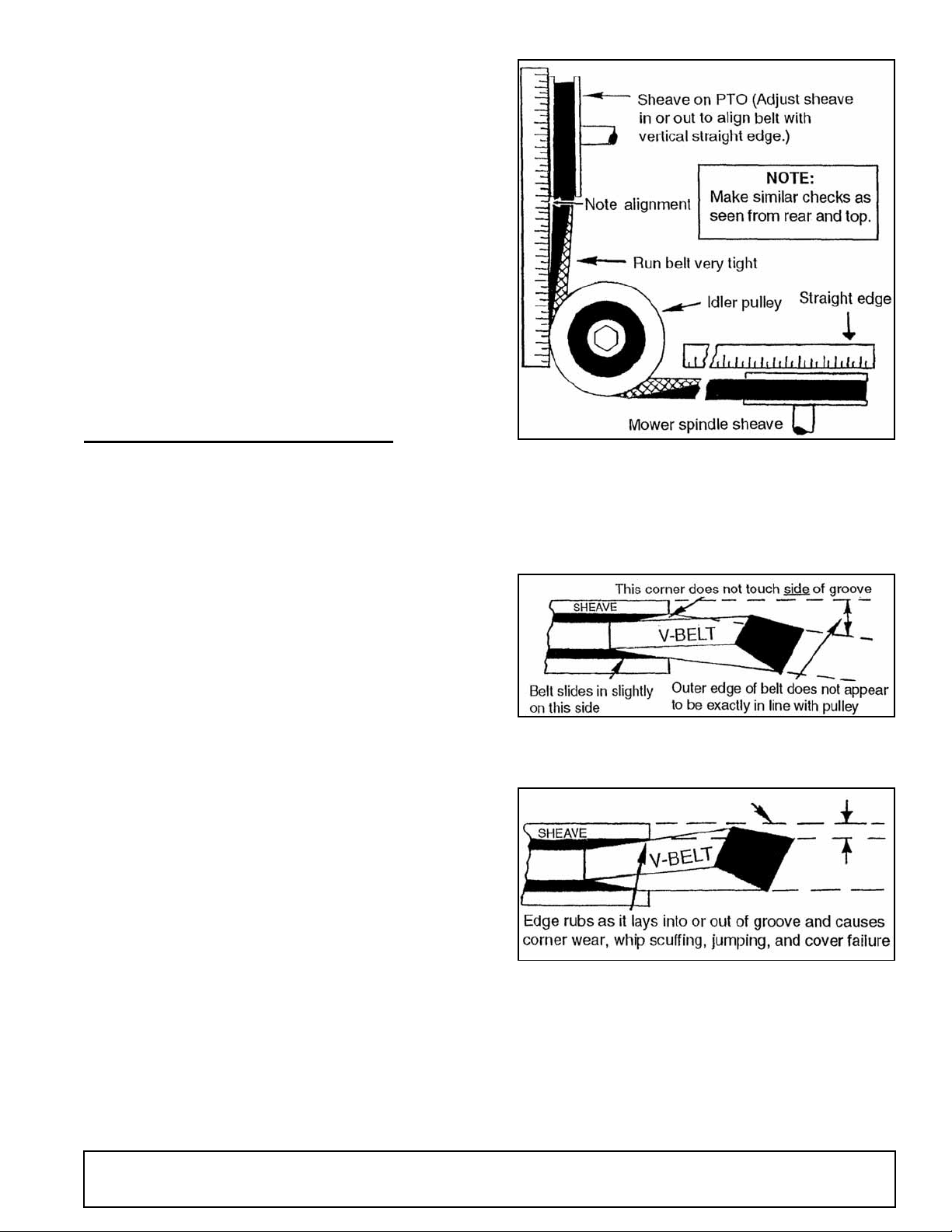
HOW TO SOLVE BELT PROBLEMS
Assemble as shown on mower decal. If not installed
correctly, more twist will result than is allowable.
Belt whip is c aus ed by be lt m isa l ig nme nt unl e ss m owe r
is driven by a rough-running or 2-cylinder engine.
Proper position of L59 and L306: Adjust mower forward and back to suc h a position tha t the rear take-u p
idlers are near the bottom of their slots when the belt
lines up with the proper groove in the center pulley and
is tight. Never run the id ler s hig h in the s lo ts as thi s will
cause misalignment.
Figure 3. Use of Straight Edge (Side View)
How to Align a Twisted Belt
Right: Inside edge of belt are approximately lined up
with the sheave.
It is assumed that the mower is adjusted to run approximately level. If the front of the mower is down, the
idlers will have to be rais ed. If the bac k of the m ower is
down, the idlers will have to be down further. Belts
must be in proper alignment with sheave grooves as
shown in Figure 4 and Figure 5.
PTO pulleys must be moved in or ou t to c ause the belt
to be in alignment with the idlers.
Belt Tension: Run belts very tight. Present belt
designs are much strong er tha n we are a ccustom ed to
and will stand more tensi on. Slip ping will hea t and rui n
a belt but tension i s not h armful. You can minimize the
amount of change in belt length as mower is raised and
lowered by keeping the rear idlers adjusted to a low
position.
Figure 4
Wrong: Outer edge of belt appears to be in line.
Figure 5
29936 (Rev. 5/18/2007)
Operation 9
Page 10

ASSEMBLY
Center Shield
To allow more lift on tractors with minimum ground
clearance, such as Fords, IH LoBoy, Kubotas, Satohs,
etc., a center belt shield is not offered. Refer to
page 24. If the box of parts has a center belt shield, bolt
center belt shield bracket (34) to deck with 3/8 x 1" bolt.
Bolt center shield (10) to bolts welded in deck and
bracket (34).
To provide clearance between tractor muffler and left
belt shield on L306, see page 24.
Side Skids
Bolt skids in such a position that they will be carried
close to the ground, b ut so they do not ride c ontinual ly
on the ground when mower is operated at desired
mowing height.
On 59’s, use 3/8 x 1" heat-tr eated bolts (torque to 35
lbs-ft), lock washer and nuts. On L306’s, use 1/2 x
1-1/4" heat treated bolts, lock washers and nuts.
Front Toe Guard
Refer to page 24. Front toe guards (6) are furnished for
some mowers. When provided, bolt them to the front of
the mower, using 3/8 NC x 3/4" carriage bo lts and 3/8"
flange lock nuts. (NOTE: On 59 and L59 where casters
are installed on outer deck rails, bolt toe guards to
mower so outer ends are abo ut 2" in from end of dec k.
Otherwise, end of toe guard will be about 1/2" in from
end of deck.) End of L306 toe guard will be 3/4" in from
end of deck.
Crosswise Rear Support
Casters
If casters are used, see page 27 or page 28, except for
the L59 mower on Ford 1000, 1600, 1700, 1900, and
Satoh S650. (Se e moun ting f rame drawing in ma nual.)
L306 caster assembly will not fit on IH424, 2424, 444,
2444, 454 and 2400; John Deere 1010 & 1020 ; Deutz
2506, 3006 and other tractors with swept back front
axle as they will hit front tires. Caster wheels cannot be
used on GM4 mounting.
L306 Casters
On Ford 8N, Massey 135, Deutz 4006, IH 354, and
2300 with straight front axle, etc., the right caster
should be put on side ang le, bolting it ov er side shield
and between side angle and right skid. Left caster
should attach to short bar on deck so casters will be
inside of left front tire. Left front tr actor tire should be
moved out to clear caster wheel. On Ford 1000, Kubota
tractors, etc., both arms will bolt to the outer de ck r ai ls.
Caster wheels cannot be used on GM4 mounting.
Front Roller Assembly Instructions
Refer to page 24. O n 59 mowers, put it em (28) on left
side and item (27) on right side of mower using 3/8"
carriage bolts and nuts.
On L306 mowers, item (28) goes on right side and item
(27) on left. This will put the highest hole in brackets
rearward on 59 and the next to the hi ghest hole rearward on L306.
Assemble roller and roller rod (26) in rear holes in
brackets (27 & 28). Se cure with 3 /16" cotte r pins. Turn
roller by hand to see that it turns freely.
Refer to page 24. Ins tall bushing (16) into center h ole
in crosswise rear s upport and bolt it to back of mo wer
deck with short bar forward and offset up using 1/2 x 2"
hex head cap screw and 1/2" flange lock nut. NOTE:
On L59, L306F10-2, “S”, JD85, JD95, and GM4 mountings, a special crosswise rear support is provided. If
tractor is equipped with turf tires, use upper center hole
in crosswise supp ort, and for Ag tires, us e lower hole.
See mounting frame drawing in those manuals.
Channel Arms
Refer to page 24. Slide mower under tractor. Attach
channel arms (12 ) to mower frame using 5/8 x 1-1/2"
clevis pin and safe ty pins. Pin crosswise rear supp ort
bar (15) between channel arms and bolt center to
frame angle bracket as shown.
10 Assembly
MOUNTING FRAME ASSEMBLY
Refer to page 18.
Idler & Mounting Bracket Assembly
Remove bolts holding front end of drawbar in place.
Slide idler brac ket (6) betw een tract or wheel h ousings,
with idler slides rearward, and bolt to the center set of
holes in rear wheel housings, using holes in idler
bracket.
Use two 7/16" thick shims at eac h front hole between
the end plates and the tractor whe el housings. If necessary, also use 5/8" flat washers. Assembly using
either 1/2" or 5/8 x 2-1/4 bolts and lock washers.
Idler Assembly to Idler Bracket
Install one V-groove idler (2) to left side of front verticl e
slot by installing three 5/ 8" flat washers between idler
29936 (Rev. 5/18/2007)
Page 11

and idler bracket. Install 5/8 x 2-1/2 carriage bolt
through slot and idler , and secure with 5/8" nut and lock
washer.
Install a 5/8 x 3" bolt through second idler. Put these
5/8" flat washers over bolt, and install assembly to right
side of rear vertical slot in idler bracket. Secure with a
5/8" flat washer and nut.
After drive belt has been installed, install rear belt
shield (19) ov er bolt installed in rear id ler and secure
with another 5/8" nut and two 5/8" flat washers.
longer chain ( 17), and sec ure by in stalling 3/1 6" sa fety
pin (16) through end of link in chain (15).
Adjust chain s so t he mow er r ais es le vel w itho ut pull in g
sideways or hitting rear tires. Also adjust chain so
mower does not hit bo ttom of t ractor or tires when ful ly
raised.
Check to make sure the lift triangle does not hit the
tractor starter. If it does, use washers to sh im lift triangle or lift support frame away from tractor.
If manual height adjustment is used, refer to page 22.
Drive Sheave
Remove paint from bo re of drive sheave. Install lar ge
drive sheave onto tractor belt pulley s haft using tractor
key and nut. A flat washer is provided to be installed
between nut and sheave. If your trac tor has a tapered
shaft which is too small for this sheav e (made prior to
1939), it will be necessa ry to install a late model belt
pulley shaft (AC part 208959) or to build up the old
shaft with shims or weld to fit.
Belt Assembly and Adjustment
Slide mower under tractor and pin push channel to idler
bracket with 5/8 x 1-3/4 clevi s pi n. Put bel t on, see Bel t
Assembly and Adjustment. Make major adjustments by
sliding mower fore and aft using 6 holes in channel arm
as required. Make minor adjustments with idlers.
Lift Assembly
Attach the lift frame (11) to tractor using upper right
hand clutch housing hole for front end of the bracket
and 1/2" vertical hole i n square tubing on tractor foot
rest for the rear attaching point.
T rac tor Whe el Adjustment
On model “B” tractors, the right tire may be fully
extended and the mow er will cut bey ond it, but th e left
rear tire must be moved in if the mower is to cut clear.
For model “C” tractors, the right tir e must be pu t within
four inches of its most inward position for the mower to
cut beyond the tire track. With the left tire in its most
inward position, the mower will still not quite cut
beyond the tire track.
Belt Assembly and Adjustment
Models used on: 59C, L59, and L306 model AC52,
AC54, BMC, B-25, D, D10-D12, F, F10, H3, GM2,
GM4, JD85, JD95, JM, K17, K2 2, K28, KD, KL, K210,
K260, MF, M25, S, S55, VC, U, etc.
First put belt on the bottom groove, right hand side of
the center sheave. Then thread it to left, around the left
hand sheave.
For hydraulic lift, assemble triangular plate (12) onto lift
frame using 5/8 x 2- 1/4 b olt ( 39), bush ing (13) , two flat
washers, and lock nut with forked end rearward and
down.
Remove cylinder from rear of trac tor, remove hose and
install longer hose provided, using 45° swivel a daptor
between valve and hose. In stall 90° swi vel en d of h os e
in cylinder and st raight end in 45° adaptor previous ly
installed.
Install cylinder onto attaching frame on ins ide of frame
at the threaded hole using a 5/8 x 3" bolt. Put bolt
through cylinder, then run a nut up on the bolt, screw
bolt through the plate, install a nut on outside and
tighten. Use a 7/16" c levis pin and cotter pin to attach
the cylinder to the triangular plate.
Attach 33-link chain (17) to keyhole lug on mower deck
and secure with pla stic c aplug (14). A ttach 7-li nk ch ain
(15) to triangular plate with 3/8 x 1-1/4 " bolt and flange
lock nut. Connect the cha ins together by installing the
lower end of 7-link chain (15) through the middle of
29936 (Rev. 5/18/2007)
Figure 6.
Assembly 11
Page 12

Bring the belt back across the center sheave in the
center groove over to the right outside sheave.
Figure 7.
Then thread it back across the front of the center
sheave in the top groove.
leave a 1/4 twist in th e section of belt extending fro m
the right V-idler to lower groove of the center mower
sheave.
Adjust the mower to p roper cutting heig ht. The front of
the mower should be slightly lower than the rea r of the
best cutting and least power requirement.
Idler Adjustment: Make minor belt adjustment with
idlers but keep left idler about 1" above being in line
with the groove in which the belt runs on the center
sheave of the mower and right idler about 1" below.
Move mower fore and aft for major adjustments. On
L306K210, K260, S, and F10, use bel t takeup id lers on
mower deck for major adjustment.
LEAF MULCHER (OPTIONAL)
1. Turn the mower upside down on saw horses. If
mower has a bolt-on front shie ld, adjust shield all
the way down in l ong slots. Remove side sh ields.
Leave side skids on. If optional front roller has
been installed, it must be removed.
2. On mowers with bent-down front frame, remove
center baffle and drill three 7/16 diameter holes
(two on 59’s) in front of mower at the diameter
shown on drawing.
3. Attach slotted angles (2) or (3 & 4) to lea f mulcher
as shown on drawing.
Figure 8.
Proper Twist: The belt then follows with a 3/4 twist
back under the left V-idler, up over the drive sheave
and back down under the right idler pulley. This will
4. Place leaf mulc her over blades on mower. Attach
angles (2) or ( 3 & 4) and mower side shiel d to s id e
frame angle on mower. All 59 mowers and L306
mowers with bolt-on front shield will use front
shield hole to attach angles (2) or (3 & 4). L306
mowers with bent-down front frame will use 2nd
hole behind skid to attach angl es (3 & 4). Bolt side
shields to mower using 3/8 flat washers for spacers.
5. On mowers with bolt-on front shield, bolt front of
leaf mulcher to bottom of slots in front shield with
3/8 x 1" bolts and flat washers. On mowers with
bent-down front frame, bol t leaf mulcher to inside
of mower in holes drilled in front frame using 3/8 x
1" bolts on L306, and on L59’s use 3/8 x 1-1/2
bolts and 5/8 long pipe spacers between leaf
mulcher and mower. On some mo wers where 5/8"
pipe may be too long, substitute 3/8 flat washers.
6. Drill 7/16 holes in rear of mower deck through
holes in leaf mulcher rear plates and bolt rear of
leaf mulcher to deck using 3/8 x 1" bolts.
7. Tighten all bolts securely. Turn each blade individually inside the l eaf mulc her to see that it clears th e
leaf mulcher ri ngs. If necessary, the rings may be
re-shaped with a hammer to clear the le af mulcher
rings.
12 Assembly
29936 (Rev. 5/18/2007)
Page 13

Figure 9. L59-AC/C & L306-AC/C Mounting Frame Assembly Photo
29936 (Rev. 5/18/2007)
Assembly 13
Page 14

Figure 10. L59-AC/C & L306-AC/C Mounting Frame Assembly Photo
14 Assembly
29936 (Rev. 5/18/2007)
Page 15

Figure 11. L59-AC/B&C & L306-AC/B&C Hydraulic Lift Assembly Photo
29936 (Rev. 5/18/2007)
Assembly 15
Page 16

Figure 12. L59-AC/B&C & L306-AC/B&C Manual Lift Assembly Photo
16 Assembly
29936 (Rev. 5/18/2007)
Page 17

NOTES
29936 (Rev. 5/18/2007)
Assembly 17
Page 18

L59-AC/B & C & L306-AC/B & C Mounting Frame
18 Parts
29936 (Rev. 5/18/2007)
Page 19

L59-AC/B & C & L306-AC/B & C Mounting Frame
REF PART QTY DESCRIPTION
10
11
12
13
14
15
16
17
18
19
1
1
2
3
4
5
6
6
7
8
9
3652
10859
4336
4335
6095
7451
9201
9376
7453
----7444
7443
10750
7445
1791
18336
6911
18270 *
4154
13006
25558
V-belt, special W188 (for L59) -or-
1
V-belt, special W205 (for L306)
1
V-idler sheave with bearing
2
V-idler sheave less bearing
2
Bearing
2
Drive sheave 8B P.D.
1
Idler and mounting frame to fit Allis
1
“C” -or-
Idler and mounting frame to fit Allis
1
“B”
5/8 x 1-3/8 x 7/16 Thick flat washer
4
Manual lift (see page 22)
-
1/4 x 1/4 x 45° Swivel street ell (opt)
1
1/4 x 42 One wire braid hyd hos e
1
(opt)
Lift support frame
1
Hyd lift triangular assembly (opt)
1
5/8 x 1 x 9/16 Hard steel sleeve
1
Plastic caplug
2
7 Link chain
1
3/16 Safety pin
1
33 Link 3/0 Chain
1
Lift holder spring (u sed on L306 only)
1
Rear belt shield
1
REF PART QTY DESCRIPTION
31
32
33
34
35
36
37
38
39
40
41
42
43
44
45
46
47
48
49
1256 * 3/16 x 1 Cotter pin
7468 7/16 x 1-3/4 Clevis pin
25474 * 1/2 NC x 2-1/4 HHCS GR5 (used on
older Allis “B”)
3489 * 1/2 NC x 3 HHCS GR5
855 * 1/2 Lock washer
1093 * 1/2 NC Hex nut
6268 * 5/8 NC x 1-1/4 HHCS GR5 (used on
L59’s)
4548 * 5/8 NC x 1-3/4 HHCS GR5 (used on
L306’s)
12274 * 5/8 NC x 2-1/4 HHCS GR5
5836 * 5/8 NC x 2-1/2 Carriage bolts
34473 * 5/8 NC x 3 HHCS GR5
1286 * 5/8 Lock washer
692 * 5/8 Flat washer
230 * 5/8 NC Hex nut
6239 * 5/8 NC Deformed thread hex nut
1598 * 5/8 NC Hex jam nut
832 1 x 2-1/2 x 7 Washer
12169 * 3/8 NC x 1-1/4 HHCS GR5
14350 * 3/8 NC Flange lock nut
Standard hardware, obtain locally
*
29936 (Rev. 5/18/2007)
Parts 19
Page 20

REF PART QTY DESCRIPTION
1
2
3
4
5
6
7
8
9
10
10
5081KT
11
26875KT †
11
23825KT
11
25997KT †
11
13404KT
11
28328KT †
11
1015826
12
13
14
14
15
15
16
17
18
19
20
22
22
23
3761
5089
4114
4115
4107
4117
4106
1972
28897
4110
13409
692
10635
13401
10718
24184
13402
13403
13405
12313
13451
4902
2974
3490 ‡
Spindle assembly (for left hand rota-
1
tion)
Seal
2
Sleeve
1
Sel-lock pin
1
Bearing cone
2
Housing with cups
1
Bearing cup
2
Grease fitting
1
Spindle shaft with left hand thread
1
Shoulder washer 2-1/4 diameter (for
1
L59 & FM48) -or-
Shoulder washer 3 diameter (for
1
L306)
16-13/16 medium suction blade (std
1
on RM48 and FM48) -or-
16-13/16 Low suct ion bl ade (optio nal
1
on RM48) -or-
20-1/4 Medium suction blade ( stan-
1
dard on L59) -or-
20-1/4 Low su ction blade (optional
1
on L59) -or-
24-1/2 Blade (Std on L306) -or-
1
24-1/2 Low su ction blade (optional
1
on L306)
Blade bolt and washer kit (For FM48
1
& L59)
5/8 Flat washer
1
5/8 ID Cup washer (for FM48 & L59)
2
1" ID x 2-3/4 OD Cup washer (For
2
L306)
Special 1-1/2 Long bolt (for FM48 &
1
L59) -or-
Special 2-3/8 Long bolt (for L306)
1
Clutch disk 3" diameter
1
Blade stop
1
Shim washer
1
5/8 ID x 1" OD x 13/16 sleeve, hear
1
treated
Special heat treated washer
1
Spind le lo ck wre nc h (us ed on FM4 8)
1
-or-
Spindle lock wrench (used on L59 &
1
L306)
Blade bolt wrench
1
Spindles and Blades
NOTE: Repair shaft 9 and repair sleev e 3 do not have a
hole drilled in them for pin 4. After new parts have been
assembled and prop er bearing adju stment obtaine d, drill
a 3/16" diameter hole throu gh sleeve and shaft. Drive in
Sel-lock pin to hold proper bearing adjustment.
NOTE: Left hand blade r otation for “ L” series. (See page
_ for right hand rotation 59’s and yellow RM48’s.)
For maximum suction for diffi cult
*
mowing.
For use in sandy areas or where high
†
abrasive wear occurs on fin of standard blade.
Used on mower prior to 1964.
‡
20 Parts
29936 (Rev. 5/18/2007)
Page 21

Lift Chain Hook-Up Table
Mower Model
Number
42A, HB
L42AC, B&C
42C
L42U
L42VAC
L42VC
L59A, 59HB,
& L306A
59HC
L59AC, B&C
L306AC, B&C
59C
L59U, L306U
L59VAC,
L306VAC
L59VC,
L306VC
Chains Used Lift Chain Attach Plt Holes Used for Spring
Part No No Used Description
4154 1 33 Link Chain
4154 1 33 Link Chain
4154 1 33 Link Chain
17477 1 84" Twisted
cut off excess
6673 1 78" Twisted
4154 1 33 Link Chain
4154
18264
18264 3 13 Link Chain
4154
18264
4154 2 33 Link Chain
17477
18264
17477 1 84" Twisted
4154
18264
1
1
1
1
1
1
1
1
33 Link Chain
13 Link Chain
33 Link Chain
13 Link Chain
84" Twisted
13 Link Chain
33 Link Chain
13 Link Chain
To Lift
Lever Hole
B
B
B
B
B
B
A or B
Opt
A or B
Opt
A
A
A
B
B
B
B
B
B
Special
Notes
T o Ho les in
Mower
H&G O See note 4 (10)
GPH(5)
L&M See note 8 Z (8)
HTH
HRJ
GSJ
E
E
E N C&D (1, 3, 8, 9)
C&D
C&D
C&D See note 8 See note 1,3 (8)
C&D
C&D
E
U
E
U
Upper End to
Hole Let-
tered:
N
N
Q
Q
T
T
R
R
S
S
Lower End to
Hole Let-
tered:
C&D
C&D
E
E
See note 3
See note 3
E
E
C&D
C&D
(1, 3, 8, 10)
(1, 3, 8, 10)
(1, 3, 8, 9)
(5)
(5)
(1)
(7)
(7)
(1, 3, 8)
(7)
Special Notes (Refer to numbers in parentheses in above table)
1. Hook one 13-link chain between holes “C” & “D”.
2. Fasten one 10-link and one 7-link chain together.
3. Hook lower end of spring in crotch chain.
4. Hook spring into chain just above hole “H”.
5. Clamp offset end spring under flat washer on out-of-way side of bracket, where indicated.
6. Fasten two 10-link chains together for lift chain.
7. O n L306 models, u se heavy spring f urnished with m ower rather than lighter spring furn ished with manua l lift kit.
Hook to a point on tractor so most of mower weight is held by spring which will allow lift to work easier.
8. Hook upper end of spring over bushing (4). Bolt lift chain to lift lever with 3/8 x 2 bolt and nut.
9. Bolt two 13-link chains together for lift chain.
10. On IH “A” lift lever (3) goes ins ide st eering r od. On IH “B” it g oes outside s teeri ng rod. For IH "B " shim at tachmen t
plate (10) out away from tr actor us in g spacer (11), four washers (56) and b ol ts (38 ). Lift le ver may have to be bent
out slightly to clear steering rod.
29936 (Rev. 5/18/2007)
Parts 21
Page 22

Manual Height Adjustment
22 Parts
29936 (Rev. 5/18/2007)
Page 23

Manual Height Adjustment
REF PART QTY DESCRIPTION
10
11
12
12
13
14
15
16
17
18
19
20
21
22
23
24
1
2
3
4
5
6
7
8
9
-----
4155
10693
484
10706
10701
3597 *
10699
10702
9045 NS
10708
10707
13006
10750
409
1256 *
10735
9046
-----
-----
-----
11445
11446
11489
13450
Chain (see chart for chain used on
-
your mounting)
1/4 Cold shut repair link
2-3
Manual height adjustment lever
1
assembly
5/8 x 1 x 7/16 HT Sleeve
1-2
3-3/8 Long compression spring
1
Manual height adjustment cli p
1
1/8 x 1 Cotter pin
1
Manual height adjustment rod
1
Manual lift sector assembly
1
IHC Manual lift att a ch ment plate
1
(includes hardware & spacer)
IHC Manual height adjustment
1
spacer (used on IHC “B” & “C”)
8-1/8 Long extension spring (used on
1
42’s & 59’s) -or-
13-1/4 Long extension spring (used
1
on L306’s)
Allis Chalmers “B” & “C” lift mounting
1
frame assembly
1/2 x 2 Clevis pin
1
3/16 x 1 Cotter pin
1
Lift attachment assembly
1
Case VAC manual lift moun ting
1
Case VC lift mounting lug (no longer
1
available)
Case VC manual lift bracket (no
1
longer available)
Case VC manual lift weldment (no
1
longer available)
Manual lift radius bracket
1
Manual lift bar
1
John Deere “B” offset manual lift
1
brace
1/4 Keystone connecting link
1
REF PART QTY DESCRIPTION
17410
25
18336
26
30
31
32
32
33
34
35
36
37
38
39
40
41
42
43
45
46
47
48
49
50
51
52
53
54
55
56
2457 * 1/4 NC x 3/4 HHCS GR5
6128 * 1/4 NC Hex lock nut
12735 * 1/2 NC x 1-3/4 Carriage bolt GR5
10284 * 1/2 NC x 2 Carriage bolt
3489 * 1/2 NC x 3 HHCS GR5
855 * 1/2 Extra-heavy lock washer
1093 * 1/2 NC Heavy hex nut
3598 * 1/2 SAE Flat washer
6268 * 5/8 NC x 1-1/2 HHCS GR5
12274 * 5/8 NC x 2-1/4 HHCS GR5
11854 * 5/8 NC x 2-1/2 HHCS GR8
986 * 5/8 x 2-3/4 HHCS GR5
1286 * 5/8 Heavy lock washer
230 * 5/8 NC Hex nut
692 * 5/8 Standard flat washer
24576 * 1/2 NC x 1-3/4 HHCS GR5
7832 * 5/8 NC x 1-1/2 HHCS GR5
4616 3/4 NC x 1-1/2 HHCS GR5
2522 * 3/4 Standard lock washer
1257 * 3/4 Standard flat washer
902 * 5/8 NC x 2 HHCS GR5
1450 * 3/4 NC Hex nut
3231 * 3/8 NC x 2 HHCS GR5
565 * 3/8 Standard flat washer
838 * 3/8 Standard lock washer
835 * 3/8 NC Hex nut, plated
25728 5/8 x 2 x 1/2 Flat washer (for IH “B”
IH Cub manual lift mounting plate
1
Caplug, 1-1/16 - 121D SAE thread
2+
-or-
only)
Obtain locally
*
29936 (Rev. 5/18/2007)
Parts 23
Page 24

59, L59, & L306 Mower Frame Assembly
24 Parts
29936 (Rev. 5/18/2007)
Page 25

REF
1
2
3
4
4
5
59, L59, & L306 Mower Frame Assembly
Model
Red &
Yellow
Mowers
25513 25511 24189 13426
25512 25510 24188 13426
26559 25997 28328 28328
26520 26521 26522 -----
Model
L59
White
Mowers
9700 9701 9702 9702
6950
23825
-or-
-or-
L306
Mowers
1976 &
Later
13404
-or-
Mowers
Prior to
L306
1976 QTY DESCRIPTION
Frame only
1
Left side shield
1
Right side shield
1
13404
-or-
Blade, medium suction (std.)
3
Blade, low suction (opt)
3
Side discharge chute
1
(a) For all 59, L59 models except: GM2, LB,
F10, F13, F15, H284, JD85, JD95, K17,
K18, K210, K260, S, S55, S-BL, TB, YM;
For all L306 models except
: AC54, GM2,
GM4, H284, JD85, JD95, K22, K24, K210,
K260 & S-BL.
(b) For use on 59, L59 models
: LB, K17,
K18, K210, K260, S55 , S-BL, TB, YM; For
use on L306 models: AC54, GM2, K22,
K24, K210, K260 & S-BL.
(c) For F10, F13, F15, GM4, H284, JD85,
JD95, S; See mounting frame assembly
drawing for items 12 & 15.
REF
6
7
8
9
10
10
11
11
12
12
13
14
15
15
16
17
18
18
19
20
21
22
23
23
24
59 & L59
3-Spindle
5’ Swath
3-Spindle
6’ Swath QTY DESCRIPTION
26516 25623
----- -----
4141 13428
25506 25528
25555 25555
4130 4130
25507 25529
----- 25547
13314 23942
18241 23928
4097 4097
410 410
3485 3485
18245 18245
3504 3504
----- -----
5753 13421
52311 52311
6126 13417
4227 4227
3885 3885 *
4226 12622
----- -----
----- -----
4142 13429
L306
Front toe guard
2
Casters (opt) (see page 27)
1pr
Right side skid
1
Right belt shield
1
Center belt shiel d (use wh en
1
front of mower is bent down)
-or-
Center belt shiel d (use wh en
1
front shield is bolted on
mower)
Left belt shield -or-
1
L306 Left belt shield, short
1
Channel arms (see a & b)
2
-or-
Channel arms (see b & c)
2
5/8 x 1-1/2 Clevis pin
4
5/8 x 1-3/4 Clevis pin
2
Crosswise rear support (se e
1
a & c) -or-
Crosswise rear support ( see
1
b & c)
1/2 x 5/8 x 1-1/16 Sleeve, HT
1
Leaf mulcher (opt)( see pg
1
26)
Complete decal set -or-
1
French safety decal set
1
Sheave (3-groove)
1
H3/4 St bushing with bolts
3
3/16 x 3/16 x 1-1/4 Key
3
Sheave (single-groove)
2
Spindle, blade & wrench kit
3
(white, left-hand blade rotation) (see pg 20) -or-
Spindle, blade & wrench kit
3
(red or yellow, right hand
blade rotation) (see pg 20)
Left side skid
1
59 & L59
3-Spindle
REF
5’ Swath
25
26
27
28
29
30
31
32
33
34
REF PART DESCRIPTION
40
41
42
43
44
45
24650 24650
24583 24583
24587 24587
24586 24586
5818 -----
25508 ----- †
25509 25533
25532 25532
25531 25530
25557 25557
2688 * 1/8 Safety pin
1256 * 3/16 x 1 Cotter pin
10378 * 1/4 NC x 1 HHCS GR5
1985 * 1/4 Standard lock washer
24597 *3/8 NC x 3/4 Carriage bolt
6697 * 3/8 NC x 1 Carriage bolt
46
47
48
14350 3/8 NC Flange hex lock nut
49
50
51
52
4119 1/2 NF x 1 HHCS GR5
6100 * 1/2 NC x 1-1/4 HHCS GR5
3699 * 1/2 NC x 2 HHCS GR5
53
54
55
1093 1/2 NC Heavy hex nut
11900 1/2 NC Flange hex lock nut
L306
3-Spindle
6’ Swath QTY DESCRIPTION
Front roller complete (opt)
1
Front roller, bearing & rod
1
Left front roller bracket
1
Right front roller bracket
1
Front shield (for mowers
1
prior to 1976)
Front corne r baffle
1
Center baffle
1
Rear mounting angle
1
Front mounting lug
1
Center belt shield bracket
1
839 * 3/8 NC x 1 HHCS GR5
838 * 3/8 Standard lock washer
835 * 3/8 NC Hex nut, plated
855 * 1/2 Extra-heavy lock washer
* Standard hardware, obtain locally
† For mowers sold after 1976. Mower frame
will have front of mower formed down.
Before this time, mower ha d a bolt-o n front
shield.
29936 (Rev. 5/18/2007)
Parts 25
Page 26

REF PART DESCRIPTION
59 & L306 Leaf Mulcher
A
A
1
2
3
4
5
7
8
9
10
11
Operation: To do a satisfactory job of leaf
mulching, the mower should be adjusted so
blades are about
1-1/2" above ground and the back of the
mower slightly lower than the front. The
mower should be run at ful l rpm w ith tra ctor
in first or second gear.
7080 Model 59 Leaf mulcher -or-
13482 Model L306 Leaf mulcher
-----
7076 Angle lug (for model 59)
13224 Right attachment bracket (for model
13225 Left attachment bracket (for model
23218 3/8 Schedule 40 pipe 5/8 long (for
839 * 3/8 NC x 1 HHCS GR5
976 * 3/8 NC x 1-1/2 HHCS GR5
565 * 3/8 Flat washer
838 * 3/8 Lock washer
835 * 3/8 NC Hex nut
leaf mulcher weldment
N/S
L306)
L306)
use only on 59 w/bent down frt frm)
* Standard hardware, obtain locally
26 Parts
29936 (Rev. 5/18/2007)
Page 27

REF PART QTY DESCRIPTION
1
2
3
3
4
4
5
7
7
8
8
9
10
11
12
13
14
15
15
16
16
16
16
17
18
29750
12243
29746 a
6761 a
29747 a
18424 a
19703
----- *
195 *
21020
1285 *
12296 *
12169 *
838 *
835 *
765 *
23479
29368 c
12242 c
29375 b
4228 b
2905 b
65578 b
22240
4181
59 & L59 Right and left caster bun dle
1
Caster yoke (includes bolt, nut & 2
1
sleeves)
Right caster arm asy, 13-5/32" long
1
-or-
Right caster arm, 16-5/32" long
1
Left caster arm asy, 13-5/32" long
1
-or-
Left caster arm, 16-5/32" long
1
8" HD Caster wheel with sleeve
1
Straigh t 1/4 self-tapping grea se fitting
1
(for steel wheel) -or-
Straight 1/8P thread grease fitting
1
(for polyethylene wheel)
1/4 x 1-1/4 Spirol pin -or-
1
1/4 x 1-1/2 Co tter pin
1
1/4 - 28 Str aight grease fit ting, 15/32"
1
long
3/8 NC x 1-1/4 HHCS GR5
2
3/8 Standard lock washer
2
3/8 NC Hex nut, plated
2
1/2 NC Hex lock nut
1
1/2 NC x 5 HHCS GR5
1
1/2 x 3/4 OD x 3-3/8 Sleeve -or-
1
17 GA Wall x 5/8 OD x 3-3/8 tube
1
3/4 Bore flanged bearing for 1-1/8
2
hole -or-
5/8 Bore flanged bearing for 1-3/8
2
hole -or-
5/8 Bore flanged bearing for 1-1/8
2
-or-
3/4 Bore x 1.385 flanged wheel bear-
2
ing with groove
3/4 x 1-3/16 x 10 GA Washer
2
25/32 x 1 x 1/2 Heat-treated sleeve
2
59 Casters
*
29936 (Rev. 5/18/2007)
Standard hardware, obtain locally
Parts 27
Page 28

REF PART QTY DESCRIPTION
A
1
2
3
4
5
6
7
8
8
9
9
10
11
12
13
14
15
16
16
17
17
17
17
24095
13400
15638
23857
13435
13444
13444
1972 *
21020
1285 *
----- *
195 *
976 *
838 *
835 *
11900 *
24576
23479
29368 c
12242 c
29375 b
4228 b
2905 b
65578 b
L306 Caster assembly bundle
-
Caster assembly
1
10" Caster wheel with sleeve
1
Caster wheel yoke assembly
1
Caster arm assembly
1
Left caster adjustment bracket
1
Right caster adjustment brack et
1
1/4 - 28 Straig ht thread grease fit ting,
1
15/32" L
1/4 x 1-1/4 Spirol pin -or-
1
1/4 x 1-1/2 Cotter pin
1
Straight 1/4 self-t apping greas e fitting
1
(for steel wheel) -or-
Straight 1/8P thread grease fitting
1
(for polyethylene wheel)
3/8 NC x 1-1/2 HHCS GR5
1
3/8 Standard lock washer
1
3/8 NC Hex nu t, plated
1
1/2 NC Flanged hex lock nut
3
1/2 NC x 1-3/4 HHCS GR5
2
1/2 NC x 5 HHCS GR5
1
1/2 x 3/4 OD x 3-3/8 Sleeve, HT -or-
1
17 GA Wall x 5/8 OD x 3-3/8 tube
1
3/4 Bore flanged bearing for 1-1/8
2
hole -or-
5/8 Bore flanged bearing for 1-3/8
2
hole -or-
5/8 Bore flanged bearing for 1-1/8
2
hole -or-
3/4 Bore x 1.385 flanged wheel bear-
2
ing with groove
L306 Casters
Standard hardware, obtain locally
*
For proper caster arm identification,
a
refer to dimension “L” as shown on
drawing. The caster arms may be
used on either side to obtain best fit.
Measure old bearing.
b
Measure outside diameter of old
c
sleeve.
28 Parts
29936 (Rev. 5/18/2007)
Page 29

BOLT TORQUE CHART
Always tighten hardware to these values unless a different torque value or tightening procedure is listed for a specific
application.
Fasteners must always be replaced with the same grade as specified in the manual parts list.
Always use the proper tool for tightening hardware: SAE for SAE hardware and Metric for metric hardware.
Make sure fastener threads are clean and you start thread engagement properly.
All torque values are given to specifications used on hardware defined by SAE J1701 MAR 99 & J1701M JUL 96.
SAE SERIES
A
A
Diameter
(Inches)
1/4" 7/16" 6 8 10 13 14 18
5/16"1/2"121719262737
3/8"9/16"233135474967
7/16"5/8"3648557578106
1/2" 3/4" 55 75 85 115 120 163
9/16" 13/16" 78 106 121 164 171 232
5/8" 15/16" 110 149 170 230 240 325
3/4" 1-1/8" 192 261 297 403 420 569
7/8" 1-5/16" 306 416 474 642 669 907
1" 1-1/2" 467 634 722 979 1020 1383
TORQUE
CHART
Wrench
Size
SAE Grade 2
(No Dashes)
SAE 2 SAE 5 SAE 8
lbs-ft N-m lbs-ft N-m lbs-ft N-m
METRIC SERIES
A
TORQUE
CHART
COARSE THREAD FIN E THREAD
A A
Diameter &
Thread Pitch
(Millimeters)
6 x 1.0 10 mm 8 6 11 8 8 6 11 8 6 x 1.0
8 x 1.25 13 mm 20 15 27 20 21 16 29 22 8 x 1.0
10 x 1.5 16 mm 39 29 54 40 41 30 57 42 10 x 1.25
12 x 1.75 18 mm 68 50 94 70 75 55 103 76 12 x 1.25
14 x 2.0 21 mm 109 80 151 111 118 87 163 120 14 x 1.5
16 x 2.0 24 mm 169 125 234 173 181 133 250 184 16 x 1.5
18 x 2.5 27 mm 234 172 323 239 263 194 363 268 18 x 1.5
20 x 2.5 30 mm 330 244 457 337 367 270 507 374 20 x 1.5
22 x 2.5 34 mm 451 332 623 460 495 365 684 505 22 x 1.5
24 x 3.0 36 mm 571 421 790 583 623 459 861 635 24 x 2.0
30 x 3.0 46 mm 1175 867 1626 1199 1258 928 1740 1283 30 x 2.0
Wrench
Size
N-m lbs-ft N-m lbs-ft N-m lbs-ft N-m lbs-ft
MARKING ON HEAD MARKING ON HEAD
Metric 8.8 Metric 10.9 Metric 8.8 Metric 10.9
SAE Bolt Head
Identification
8.8
Metric
Grade 8.8
SAE Grade 5
(3 Radial Dashes)
MARKING ON HEAD
Metric Bolt Head
Identification
SAE Grade 8
(6 Radial Dashes)
10.9
Metric
Grade 10.9
Diameter &
Thread Pitch
(Millimeters)
Typical Washer
Installations
Lock W ash er
Bolt
Bolt Torque & Size Charts (Rev. 3/28/2007)
Flat Washer
8/9/00
Appendix 29
Page 30

BOLT SIZE CHART
NOTE: Chart shows bolt thread sizes and corresponding head (wrench) sizes for standard SAE and metric bolts.
SAE Bolt Thread Sizes
5/16 3/8 1/2 5/8 3/4 7/8
IN 1 7
2
34
5
6
MM 25 50 75 100 125 150 175
Metric Bolt Thread Sizes
8MM 18MM14MM12MM10MM 16MM
ABBREVIATIONS
AG.............................................................. Agriculture
ASABE ....................American Society of Agricultural &
Biological Engineers (formerly ASAE)
ASAE ... . ... American Society of Agricultural Engineers
ATF................................Automatic Transmission Fluid
BSPP.............................British Standard Pipe Parallel
BSPTM................ British Standard Pi pe Tapered Male
CV ....................................................Constant Velocity
CCW.............................................. Counter-Clockwise
CW .............................................................. Clockwise
F.......................................................................Female
FT................... ........................................... Full Thread
GA.....................................................................Gauge
GR (5, etc.)........................................... Grade (5, etc.)
HHCS........................................Hex Head Cap Screw
HT ...........................................................Heat-Treated
JIC.................Joint Industry Council 37° Degree Flare
LH.................................................................Left Hand
LT ...........................................................................Left
m ........................................................................Meter
mm ...............................................................Millimeter
M ..........................................................................Male
MPa ........................................................Mega Pascal
N......................................................................Newton
NC...................................................... National Coarse
NF...........................................................National Fine
NPSM .................... National Pipe Straight Mechanical
NPT...........................................National Pipe Tapered
NPT SWF......... National Pipe Tape red Swivel Female
ORBM...........................................O-Ring Boss - Male
P ..........................................................................Pitch
PBY.......................................................Power-Beyond
psi.........................................Pounds per Square Inch
PTO............. .........................................Power Take Off
QD ...................................................Quick Disconnect
RH..............................................................Right Hand
ROPS........................... Roll-Over Protective Structure
RPM........................................Revolutions Per Minute
RT........................................................................Right
SAE..........................Society of Automotive Engineers
UNC.....................................................U nified Coarse
UNF ..........................................................Unified Fine
UNS.....................................................Unified Special
30 Appendix
Bolt Torque & Size Charts (Rev. 3/28/2007)
Page 31

WARRANTY
(All Models Except Mow’n MachineTM Zero-Turn Mowers and Woods BoundaryTM Utility Vehicles)
Please Enter Information B elow and Save for Future R eference.
Date Purchased: ____________________________ From (Dealer): ___________________________________________
Model Number: _ ___________________ ________ Serial Num ber:__________________________________________ _
Woods Equipment Company (“WOODS”) warrants t his produc t to be free fro m defect in material and workm anship. Exc ept as oth erwise set
forth below, the duration of this Wa rranty shall be for TWELVE (12) MONTHS COMMENCING ON THE DATE OF DELIVERY OF THE
PRODUCT TO THE ORIGINAL PURCHASER.
Woods backhoe models BH70-X, BH80- X , and BH90-X are warranted for two ( 2) years from the date of delivery to the orig in al purchaser.
The warranty peri ods for specific parts or condi t ions are listed below:
Part or
Condition
Warranted
BW1260, BW1800 8 years
BB48X, BB60X, BB72X, BB84X, BB600X, BB720X, BB840X, BB6000X,
BB7200X, BB840 0X, D S1260, DSO1260, DS1440, TS1680, BW126-2, BW180-2
Gearbox
components
Blade spindles
Rust-through
Under no circumstances will this Warranty apply in the event that the product, in the good faith opinion of WOODS, has been subjected to
improper operat ion, improper maintenance, misu se, or an accident. This Warranty does not apply in the event that the product has been
materially modified or repaired by someone other than WOODS, a WOODS authorized dealer or distributor, and/or a WOODS authorized
service center. This Warranty does not cover normal wear or tear, or normal maintenance items. This Warranty also does not cover repair s ma de
with parts other than those obtainable through WOODS.
This W arranty is extended solely to th e original purchaser of the product. Should th e original purchaser sell or other wise transfer this product to
a third party, this Warranty does not transfer to the third party purchaser in any way. There are no third party beneficiaries of th is Warranty.
WOODS makes n o warranty, express or implied, w ith respect to e ngines, batteries, tires or other par ts or accessories not manufactured by
WOODS. Warranties for these item s, if any, are provided separately by their respective manufacturers.
WOODS’ obligation under this Warranty is limited to, at WOODS’ option, the repair or replace ment, free of charge, of the product if W OODS,
in its sole discretion, deems it to be defective or in noncompliance with this Warranty. The pro duct must be returned to WOO D S with proof
of purchase within thirty (30) days after such defect or noncompliance is discovered or should have been discovered, routed through the
dealer and distributor from whom the purchase w as made, transportation charges prepaid. WOODS shall complete such repair or
replacement within a reasonable time after WOODS receives the product. THERE ARE NO OTHER REMEDIES UNDER THIS
WARRANTY. THE REMEDY OF REPAIR OR REPLACEMENT IS THE SOLE AND EXCLUSIVE REMEDY UNDER THIS
WARRANTY.
THERE ARE NO WARRANTIES WHICH EXTEND BEYOND THE DESCRIPTION ON THE FACE OF THIS WARRAN TY. WOODS
MAKES NO OTHER WARRAN TY, EXPRESS OR IMPLIED, AND WOODS SPECIFICALLY DISCLAIMS ANY IMPLIED WARRANTY
OF MERCHANTABILITY AND/OR ANY IMPLIED WARRANTY OF FITNESS FOR A PARTICULAR PURPOSE.
WOODS shall not be l iable for any incidental or conseque ntial losses, damages or expe nses, arising directly or indirectly from the
product, whether su ch cl aim is b ased u po n breach of co ntra ct, b reach of w arr an ty, negligence, stri ct lia bil ity in t or t or an y o the r le ga l
theory. Without limiting the generality of the foregoing, Woods specifically disclaims any damages relating to (i) lost profits, business,
revenues or goodwill ; (ii) loss of crops; (iii) loss because of delay in harvesting; (iv) any expense or loss incurred for labor, supplies, substitute
machinery or rental; or (v) any other type of dam age to property or economic l oss.
This Warranty is subject to any existing conditions of supply which may directly affect WOODS’ ability to obtain materials or manufacture
replacement parts.
No agent, repr esentative, dealer, distri butor, serviceperso n, salesp erson, or employee of any comp any, including without l imitation, WOODS,
its authorized dealers, distr ibutors, and service centers, is authoriz ed to alter, modify, or enlarge this Warranty.
Answers to any questions regarding warranty service and locations may be obtained by contacting:
PHD25, PHD35, PH D65, PHD95, 2162, 3240, DS96, DS 120, RCC42, RM550-2,
RM660-2, RM990-3, PRD6000, PRD7200, PRD8400, 7144RD-2, 9180RD-2,
9204RD-2, S15CD, S20CD, S22CD, S25CD, S27CD
RDC54, RD60, RD72
RM550-2, RM660-2, RM990-3, PRD6000, PRD7200, PRD8400, 7144RD-2,
9180RD-2, 9204RD-2
BB600, BB720, BB840, BB6000, BB7200, BB8400, BW126-2, BW180-2,
BW1260, BW1800, 2162, 3240, DS1260, DSO1260 , DS1440, TS1680
Model Number
Duration (fr om dat e of deliv ery
to the original purchase r)
6 years
5 years
3 years (1 year if used in rental or
commercial applications)
3 years
10 years
Woods Equipment
Company
2606 South Illinois Route 2
Post Office Box 1000
Oregon, Illinois 61061
800-319-6637 tel
800-399-6637 fax
www.WoodsEquipment.com
F-3079 (Rev. 6/1/2007)
Page 32

WARRANTY
(Replacement Parts For All Models Except Mow’n Machine
Zero-Turn Mowers and Woods BoundaryTM Utility Vehicles)
Woods Equipment Company (“WOODS”) warrants this product to be free from defect in material and
workmanship for a period of ninety (90) days from the date of delivery of the product to the original purchaser
with the exception of V-belts, which will be free of defect in material and workmanship for a period of 12 months.
Under no circumstances will this Warranty apply in the event that the product, in the good faith opinion of
WOODS, has been subjected to improper operation, improper maintenance, misuse, or an accident. This Warranty
does not cover normal wear or tear, or normal maintenance items.
This Warranty is extended solely to the original purchaser of the pr oduct. Should the original purchaser sell or
otherwise transfer this product to a third party, this Warranty does not transfer to the th ird party purchaser in any
way. There are no third party beneficiaries of this Warranty.
WOODS’ obligation under this Warranty is limited to, at WOODS’ option, the repair or replacement, free of
charge, of the product if WOODS, in its sole discretion, deems it to be defective or in noncompliance with this
Warranty. The product must be returned to WOODS with proof of purchase within thirty (30) days after
such defect or noncomplian ce is di scovered or should have been d iscovered, routed through the dealer and
distributor from whom the purchase was made, transportation charges prepaid. WOODS shall complete
such repair or replacement within a reasonable time after WOODS receives the product. THERE ARE NO
OTHER REMEDIES UNDER THIS WARRANTY. THE REMEDY OF REPAIR OR REPLACEMENT IS THE
SOLE AND EXCLUSIVE REMEDY UNDER THIS WARRANTY.
THERE ARE NO WARRANTIES WHICH EXTEND BEYOND THE DESCRIPTION ON THE FACE OF THIS
WARRANTY. WOODS MAKES NO OTHER WARRANTY, EXPRESS OR IMPLIED, AND WOODS
SPECIFICALLY DISCLAIMS ANY IMPLIED WARRANTY OF MERCHANTABILITY AND/OR ANY
IMPLIED WARRANTY OF FITNESS FOR A PARTICULAR PURPOSE.
TM
WOODS shall not be liable for any incidental or con sequential losses, damages or expenses, arising directly
or indirectly from the product, whether such claim is based upon breach of contract, breach of warranty,
negligence, strict liability in tort or any other legal theory. Without limiting the generality of the foregoing,
Woods specifically disclaims any dama ges relating to (i) l ost profits, business, revenues or goodwill; (ii) loss of
crops; (iii) loss because of delay in harvesting; (iv) any expense or loss incurred for labor, supplies, substitute
machinery or rental; or (v) any other type of damage to property or economic loss.
This Warranty is subject to any existing conditions of supply which may directly affect WOODS’ ability to obtain
materials or manufacture replacement parts.
No agent, representative, dealer, distributor, service person, salesperson, or employee of any company, including
without limitation, WOODS, its authorized dealers, distributors, and service centers, is authorized to alter, modify,
or enlarge this Warranty.
Answers t o any questions regarding warranty se rvice and locations may be obtained by contacting:
Woods Equipment
Company
2606 South Illinois Route 2
Post Office Box 1000
Oregon, Illinois 61061
800-319-6637 tel
800-399-6637 fax
www.WoodsEquipment.com
©2007 Woods Equipment Company. All rights reserved. WOODS, the Woods logo, and "Tested. Proven. Unbeatable." are trademarks of Woods
Equipment Company. All other trademarks, trade names, or service marks not owned by Woods Equipment Company that appear in this manual are
the property of their respective companies or mark holders. Specifications subject to change without notice.
F-8494 (Rev. 6/23/2005)
 Loading...