

Page 1
Instruction Manual
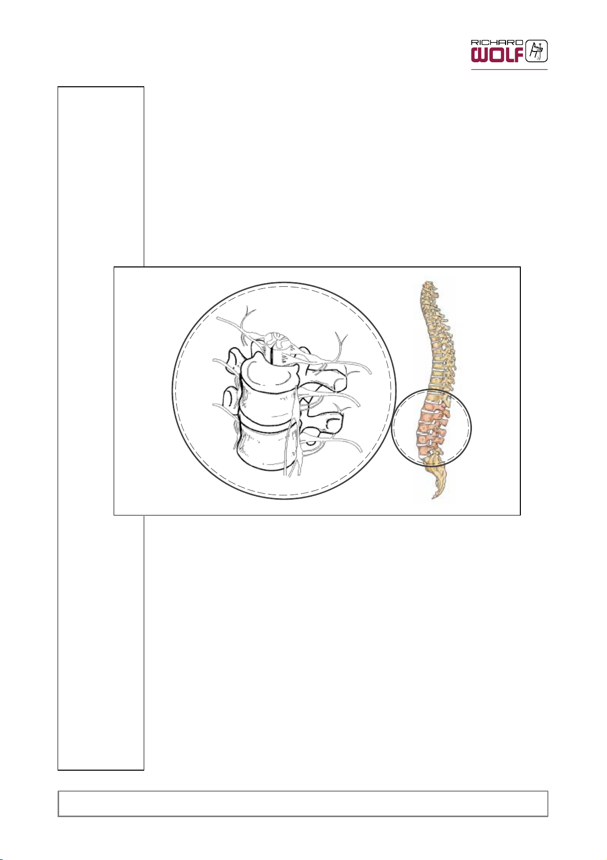
VERTEBRIS lumbar-thoracic
Full endoscopic spinal instrument set
GA-B 223 / USA / 2012-10 V5.0 / ECO 2012-0519
(RW: 07-09-7.0
/ PDZ 09-3602)
Page 2
Important general notes and instructions for use
Make sure that this product is used only as intended and described in this instruction manual, by
adequately trained and qualified medical personnel, and that maintenance and repair are only car
ried out by authorized experts.
Use the product only in the combinations and with the accessories and spare parts specified in this
instruction manual. Use other combinations, accessories and replacement parts only if they are
expressly intended for the planned application and if the performance characteristics and safety
requirements are met. The product must not be altered in any way.
Reprocess the products in accordance with the manual before every use and before return ship
ment to protect the patient, user and third parties.
Immediately upon receipt, check the product and its accessories for completeness and possible
damage. Should the shipment give right to complaints, please inform the manufacturer or supplier
immediately.
Subject to technical changes!
Due to ongoing developments, the illustrations and technical data may deviate slightly.
CAUTION :
Federal law restricts this device to sale by or on the order of a physician.
Safety instructions and levels of danger
Symbols Level of danger
WARNING!
Failure to observe can result in death or serious injury.
CAUTION!
Failure to observe can result in slight injury or damage to the product.
.
.
IMPORTANT!
Failure to observe can result in damage to the product or surroundings.
NOTE!
Tips for optimum use and other useful information.
USA
RICHARD WOLF
Medical Instruments Corporation
353 Corporate Woods Parkway
Vernon Hills, Illinois 60061
Toll Free: 001 (800) 323 - 9653
Phone: 001 (847) 913 - 1113
Fax: 001 (847) 913 - 1488
MANUFACTURER
sales@richardwolfusa.com
www.richardwolfusa.com
BELGIUM / NETHERLANDS
N.V. Endoscopie
RICHARD WOLF Belgium S.A.
Industriezone Drongen
Landegemstraat 6
9031 Gent Drongen
Telephone: +32 92 80 81 00
Telefax: +3292829216
endoscopy@richard-wolf.be
www.richard-wolf.be
Marketing Office
U.A.E
RICHARD WOLF Middle East
P.O. Box 500283
AL Thuraya Tower 1
th
Floor,
9
Room 904, Dubai
Telephone: + 9 71 43 68 19 20
Telefax: + 9 71 43 68 61 12
middle.east@richard-wolf.com
www.richard-wolf.com
GERMANY
RICHARD WOLF GmbH
75438 Knittlingen
Pforzheimerstr. 32
Telephone: +49 70 43 35-0
Telefax: +49704335-300
info@richard-wolf.com
www.richard-wolf.com
FRANCE
RICHARD WOLF France S.A.R.L.
Rue Daniel Berger
Z.A.C. La Neuvillette
F-51100 Reims
Telephone: +33 3 26 87 02 89
Telefax: +33 3 26 87 60 33
france@richard-wolf.com
INDIA
RICHARD WOLF India Private Ltd.
JMD Pacific Square
No. 211 A, Second Floor
Behind 32
Gurgaon - 122 001
National Capitol Region
Telephone: + 91 12 44 31 57 00
Telefax: +911244315705
india@richard-wolf.com
www.richard-wolf.com
nd
Milestone
UK
RICHARD WOLF UK Ltd.
Waterside Way
Wimbledon
SW17 0HB
Telephone: + 44 20 89 44 74 47
Telefax: +442089441311
admin@richardwolf.uk.com
www.richardwolf.uk.com
AUSTRIA
RICHARD WOLF Austria
Ges.m.b.H.
Wilhelminenstraße 93 a
A-1160 Vienna
Telephone: +43 14 05 51 51
Telefax: +431405515145
austria@richard-wolf.com
www.richard-wolf.com
0
GA-B 223
Page 3

Contents
1 Intended use 1..............................................................
1.1 Endoscopes, endoscope accessories 1.........................................
1.2 Suction- and Irrigation instruments 1............................................
1.2.1 Irrigation adapters, adapter 1..................................................
1.2.2 Suction connector, suction tube 1..............................................
1.3 Access instruments 1.........................................................
1.3.1 Positioning rod 1.............................................................
1.3.2 Spinal Cannula Set 1.........................................................
1.3.3 Dilators 1...................................................................
1.3.4 Working sleeves 1...........................................................
1.3.5 Attachable handles 1.........................................................
1.3.6 Trephines 1.................................................................
1.3.7 Spongiosa pusher / funnel 1...................................................
1.4 Hand and auxiliary instruments 1...............................................
1.4.1 Rasp / Trocar / Spoon / Anulotome / Dissector / Curette / Face cutter 1.............
1.5 Forceps instruments, punches, scissors 2.......................................
1.5.1 Punches, micro rongeurs 2....................................................
1.5.2 Micro punches 2.............................................................
1.5.3 Scissors 2..................................................................
1.5.4 Tubular sheath punches, bone punches 2.......................................
1.6 Motorized instruments 2......................................................
1.6.1 Abrader 2...................................................................
1.6.2 Rotary blades / Nucleus resector 2.............................................
1.7 HF / RF instruments 2........................................................
1.8 Accessories 2...............................................................
1.8.1 Deflector 2..................................................................
1.8.2 Extractor instrument ”X-tractor” 2...............................................
2 Indications and field of use 2..................................................
3 Contraindications 2...........................................................
4 Combinations 3..............................................................
5 Illustration 4.................................................................
5.1 Endoscopes, endoscopic accessories 4.........................................
5.1.1 Endoscope A 4..............................................................
5.1.2 Endoscope B 5..............................................................
5.2 Suction‐ and irrigation instruments 6............................................
5.2.1 Stopcock‐, irrigation connectors, adapters 6.....................................
5.2.2 Suction tube, suction connector 6..............................................
5.3 Access instruments 7.........................................................
5.3.1 Positioning rod 7.............................................................
5.3.2 Disposable Spinal Cannula Set 7...............................................
5.3.3 Dilators 8...............................................................
5.3.4 Working sleeve 8............................................................
5.3.5
5.3.6 Trephines 9.................................................................
5.3.7 Spongiosa pusher and funnel 9................................................
Attachable handles ......................................................... 9
....
GA-B 223
I
Page 4

5.4 Hand and auxiliary instruments 10...............................................
5.4.1 Anulotome / Dissector / Curette / Spoon / Rasp / Trocar / Face cutter 10.............
5.5 Forceps instruments, punches, scissors 11.......................................
5.6 Motorized instruments 12......................................................
5.6.1 Abraders 12..................................................................
5.6.2 Rotary blades 12..............................................................
5.7 HF / RF Instruments 13........................................................
5.7.1 Bipolar coagulations instruments and bipolar electrodes 13.........................
5.7.2 Bipolar Micro Grasping Forceps 14..............................................
5.8 Accessories 15...............................................................
5.8.1 Deflector 15..................................................................
5.8.2 Extractor instrument ”X-tractor” 15...............................................
5.9 Packaging identification 16.....................................................
6Use 17......................................................................
6.1 Preparation 17................................................................
6.1.1 Assembling the endoscopes 17.................................................
6.1.2 Attaching access instruments 20................................................
6.1.3 Motorized instruments 21......................................................
6.2 Additional notes and instructions for use 21.......................................
6.2.1 Light 21......................................................................
6.2.2 Current 22...................................................................
6.2.3 Image quality 22..............................................................
6.2.4 Irrigation fluid 22..............................................................
6.2.5 Irrigation and suction power 22..................................................
6.2.6 HF application 23.............................................................
6.3 Laser application 24...........................................................
6.3.1 Forceps instruments, punches, scissors 24.......................................
7 Checks 27...................................................................
7.1 Visual check 27...............................................................
7.2 Functional check 28...........................................................
7.2.1 Endoscopes 28...............................................................
7.2.2 Suction- and irrigation instruments 28............................................
7.2.3 Forceps instruments, punches, scissors 28.......................................
8 Reprocessing and maintenance 29..............................................
8.1 Disassembly before cleaning 29.................................................
8.1.1 Endoscopes 29...............................................................
8.1.2 Access instruments 30.........................................................
8.1.3 Forceps instruments, punches, scissors 31.......................................
8.1.4 Motorized instruments 31......................................................
8.2 Manual reprocessing 31........................................................
8.2.1 Endoscopes
8.2.2 Forceps instruments, punches, scissors 31.......................................
8.2.3 Motorized instruments 31......................................................
8.3 Machine reprocessing 32.......................................................
8.3.1 Endoscopes 32...............................................................
8.3.2 Forceps instruments, punches, scissors, nucleus resector with luer connector 33......
8.4 Checks 33...................................................................
31...............................................................
II
GA-B 223
Page 5

Contents
8.5 Assembly before sterilization 34.................................................
8.5.1 Endoscopes 34...............................................................
8.6 Sterilization 35................................................................
8.6.1 Steam sterilization 36..........................................................
8.6.2 Gas sterilization 36............................................................
8.6.3 Alternate sterilization methods 36...............................................
8.6.4 Short Endoscope Tray, Item # 88090.0007 36....................................
9 Technical data and order data 37................................................
9.1 Spare parts and accessories 37.................................................
10 Operating, storage, transport and shipping conditions. 38...........................
11 Disposal of product, packaging material and accessories. 38........................
12 Warranty and Customer Service 39..............................................
GA-B 223
III
Page 6

1 Intended use
The instruments and endoscopes serve to create the surgical passages, visualize
the operating area, manipulate and dissect tissue in endoscopic or endoscopically
supported spinal surgery.
For this purpose the instruments described in the following are used:
1.1 Endoscopes, endoscope accessories
For visualizing the operating area and the surgical instruments. The surgical instruments are introduced through the working channel or insertion port with stopcock.
Irrigation is carried out via a separate irrigation channel or the working channel.
1.2 Suction-- and Irrigation instruments
1.2.1 Irrigation adapters, adapter
For connecting the endoscopes or working sleeves to the suction and irrigation
environment.
1.2.2 Suction connector, suction tube
They allow additional or inproved aspiration of irrigation fluid, blood or ablated
particles. If necessary the suction connector can also be attached directly to the
distal end of the endoscope.
1.3 Access instruments
1.3.1 Positioning rod
The positioning rod is used to define the optimum entry point when establishing
access under image converter control.
1.3.2 Spinal Cannula Set
The spinal cannula set is used for creating primary access and injecting local
anesthetic, as well as for applying discography media.
1.3.3 Dilators
Dilators are used for blunt preparation of the access channel. The cannulated
dilators can be inserted via a guide wire.
1.3.4 Working sleeves
The working sleeves are used to secure the passage during the operation. Working sleeves are inserted via a suitable dilator.
1.3.5 Attachable handles
For intraoperative manipulation of working sleeves, without suction or irrigation
function.
1.3.6 Trephines
The trephine is used to create a window in the fibrous ring of the intervertebral
disc.
1.3.7 Spongiosa pusher / funnel
This instrument is used for implanting spongiosa.
1.4 Hand and auxiliary instruments
1.4.1 Rasp / Trocar / Spoon / Anulotome / Dissector / Curette / Face cutter
For palpating, exposing and dissecting soft tissue.
1
GA-B 223
Page 7

1.5 Forceps instruments, punches, scissors
1.5.1 Punches, micro rongeurs
are used for manipulating and withdrawing soft and cartilaginous tissue.
1.5.2 Micro punches
are used for dissecting soft and cartilaginous tissue.
1.5.3 Scissors
for the dissection of soft and cartilaginous tissue.
1.5.4 Tubular sheath punches, bone punches
are used for dissecting strong ligaments, cartilaginous tissue and osseous structures.
1.6 Motorized instruments
1.6.1 Abrader
Abraders are used for the resection of osseous structures under simultaneous aspiration of severed tissue chips.
1.6.2 Rotary blades / Nucleus resector
Resect disc core material (nucleus pulposus) under simultaneous aspiration of severed tissue chips.
They serve to palpate, expose and dissect tissue.
1.7 HF / RF instruments
For tissue coagulation, vessel coagulation, hemostasis and tissue reduction under
endoscopic view. The use of suction applicators allows additional irrigation or suction.
1.8 Accessories
1.8.1 Deflector
The deflector is used for deflecting flexible auxiliary instruments.
1.8.2 Extractor instrument ”X--tractor”
The ”X--tractor” serves to manipulate cylindrical access instruments.
2 Indications and field of use
For use in endoscopic or endoscopically supported operations of the spine.
Mainly for removing tissue, (such as prolapse material, bones, cartilage, etc.) in
order to decompress neural structures.
3 Contraindications
CJD -- Creutzfeldt--Jakob Disease or
vCJD -- Variant of the Creutzfeldt--Jakob Disease
BSE -- Bovine Spongiform Encephalopathy; the so--called mad cow disease
TSE -- Transmissible spongiform Encephalopathy
On the basis of the patient’s general condition the physician / surgeon in charge
must decide whether the planned use is possible or not.
The regulations and laws valid in your country must be adhered to.
For further information see the latest medical literature.
Contraindications directly related to the product are presently unknown.
(e.g. Creutzfeldt--Jakob disease)
GA-B 223
2
Page 8
4 Combinations
The instrument set is used in conjunction with:
Z Light sources and fiber light cables
Z Cameras and objective lenses
Z Pumps for irrigation and suction
Z HF surgical devices
Z Laser
Z Motor systems / Motorized handles
Z Endoscopic accessories
CAUTION!
Do not combine products incorrectly!
Injuries of the patient, user or third parties as well as damage to the product
are possible.
The different products can only be combined and used together if the in-
tended use and the relevant technical data (working length, diameter, peak
voltage etc.) are the same.
Follow the instruction manuals of the products used in combination with
this product.
' System Overview VERTEBRIS lumbar -thoracic BB -B 223
' Overview of motorized instruments BB- B 223- 1
' POWER CONTROLE 2303 GA- A 202
' POWER DRIVE ART1 2304 GA- A 238
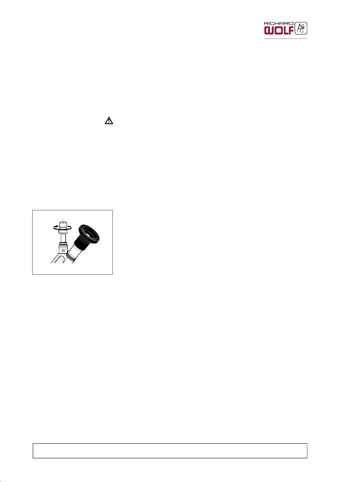
Fig. 1
1.5
The cold--light connector (1.5) can be unscrewed and replaced with suitable
adapters to connect fiber light cables made by other manufacturers (Fig. 1).
' The same applies to endoscope A.
' For order information please refer to the current catalog sheets.
3
GA-B 223
Page 9
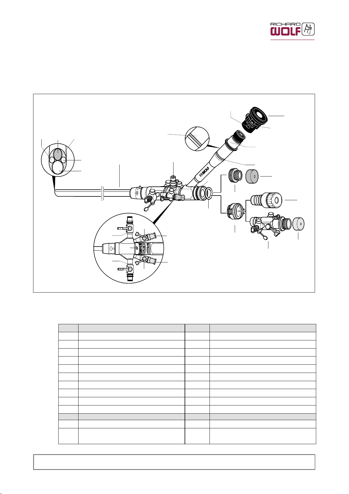
5 Illustration
5.1 Endoscopes, endoscopic accessories
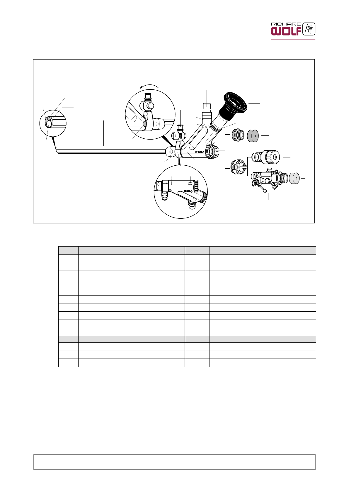
5.1.1 Endoscope A
1.1 1.2
1.3
1.1
1
1.4
2.1
2
#
#
*
1.5
1.12
3
1.6
Fig. 2
4
1.7
1.9
1.10
1.11
1.10
1.8
1.8
6
7
1.9
Legend and identification
Item Designation Item Designation
1 Endoscope 1.9 Insertion stopcock / port
1.1 Irrigation channel 1.10 Irrigation stopcock
1.2 Objective lens 2 Snap--on eyepiece with eyecup
1.3 Light exit 2.1 Locking screw
1.4 Working channel 3 Sealing cap
1.5 Cold--light adapter 4 Sealing cap adapter
1.6 Locking collar 5 Membrane adapter
1.7 Sealing membrane 6 Cone adapter
1.8 Rubber cap, red 7 Stopcock adapter
# Product no. * Serial no.
Item Designation Colour Meaning
1.1 1 Indication of viewing direction
1.12 Colored ring
red
blue
Viewing direction 20
Viewing direction 0
5
3
GA-B 223
4
Page 10
5.1.2 Endoscope B
1.3
1.4
Fig. 3
180°
1.5
1.2
1.1
1
1.14
8.1
1.15
*
35
1.12
1.6
4
8
1.11 1.13
#
1.7
6
Legend and identification
Item Designation Item Designation
1 Endoscope 2 Eyepiece with eyecup
1.1 Irrigation channel 3 Sealing cap
1.2 Objektive lens 4 Sealing cap adapter
1.3 Light exit 5 Membrane adapter
1.4 Working channel 6 Cone adapter
1.5 Cold--light adapter 7 Stopcock adapter
1.6 Locking collar 8 Irrigation adapter, rotatable
1.7 Sealing membrane 8.1 Irrigation stopcock
1.14 Locking tab # Product no.
1.15 Size of fiber core diameter * Serial no.
Item Designation Color Meaning
1.1 1 Indication of viewing direction
1.12 Colored ring red Viewing direction 25
1.13 Maximum capacity (lumen) in mm
2
3
5
3
7
5
GA-B 223
Page 11
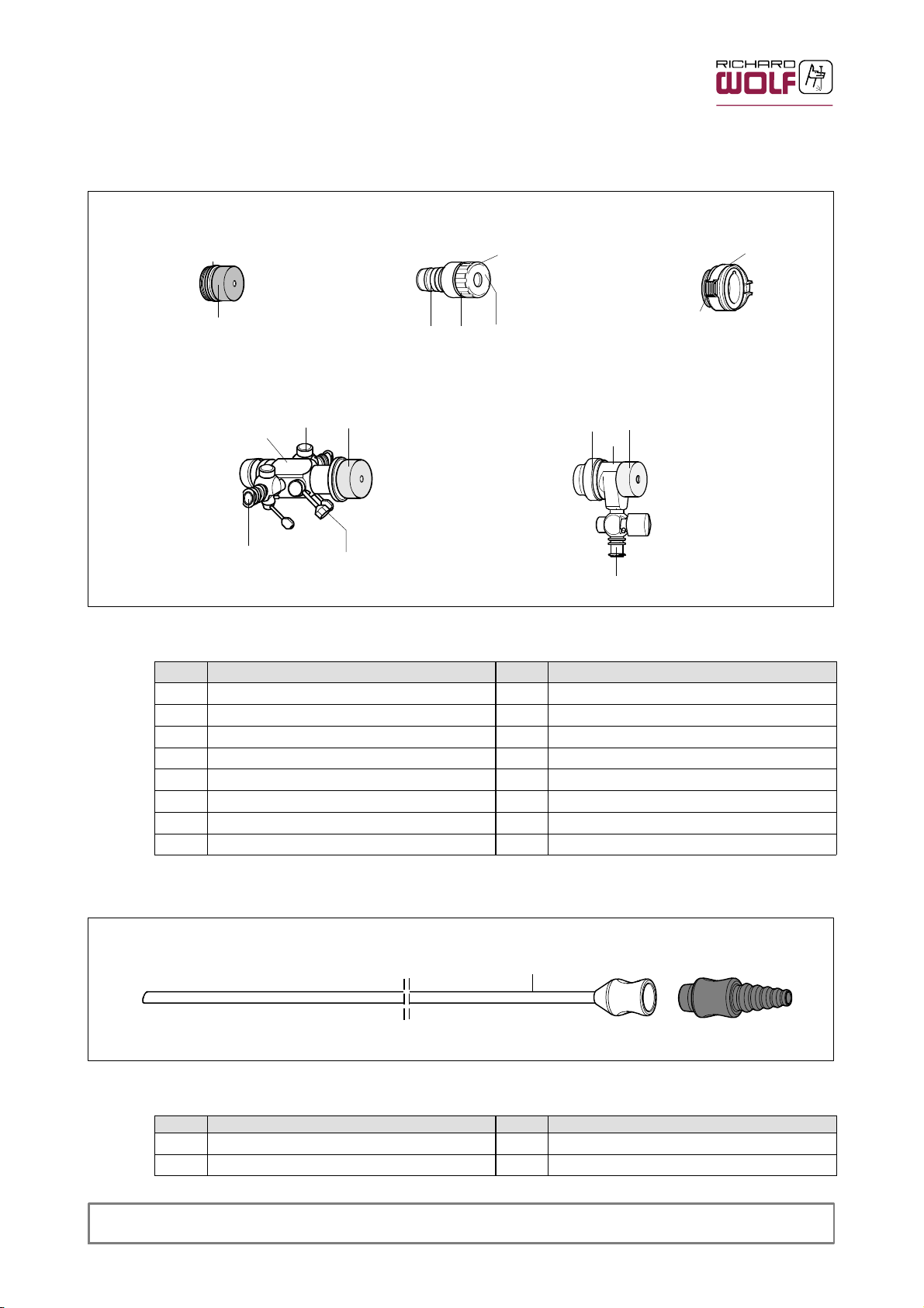
5.2 Suction- and irrigation instruments
5.2.1 Stopcock-, irrigation connectors, adapters
4 56
#
5.1
#
Fig. 4
3
7
7.1
3
#
5.25.3
#
9
9.2
3
6.1
#
7.27.1
9.1
Legend and identification
Item Designation Item Designation
3 Sealing cap 7 Stopcock adapter
4 Sealing cap adapter 7.1 Insertion stop cock
5 Membrane adapter 7.2 Irrigation stopcock
5.1 Sealing insert 9 Irrigation adapter for workling sleeves
5.2 Membrane valve 9.1 Irrigation stopcock
5.3 Adapter 9.2 Locking sleeve
6 Cone adapter
6.1 Tab # Product no.
5.2.2 Suction tube, suction connector
Fig. 5
Legend and identification
Item Designation Item Designation
10 Suction tube 11 Suction connector
GA-B 223
10
11
#
# Product no.
6
Page 12
5.3 Access instruments
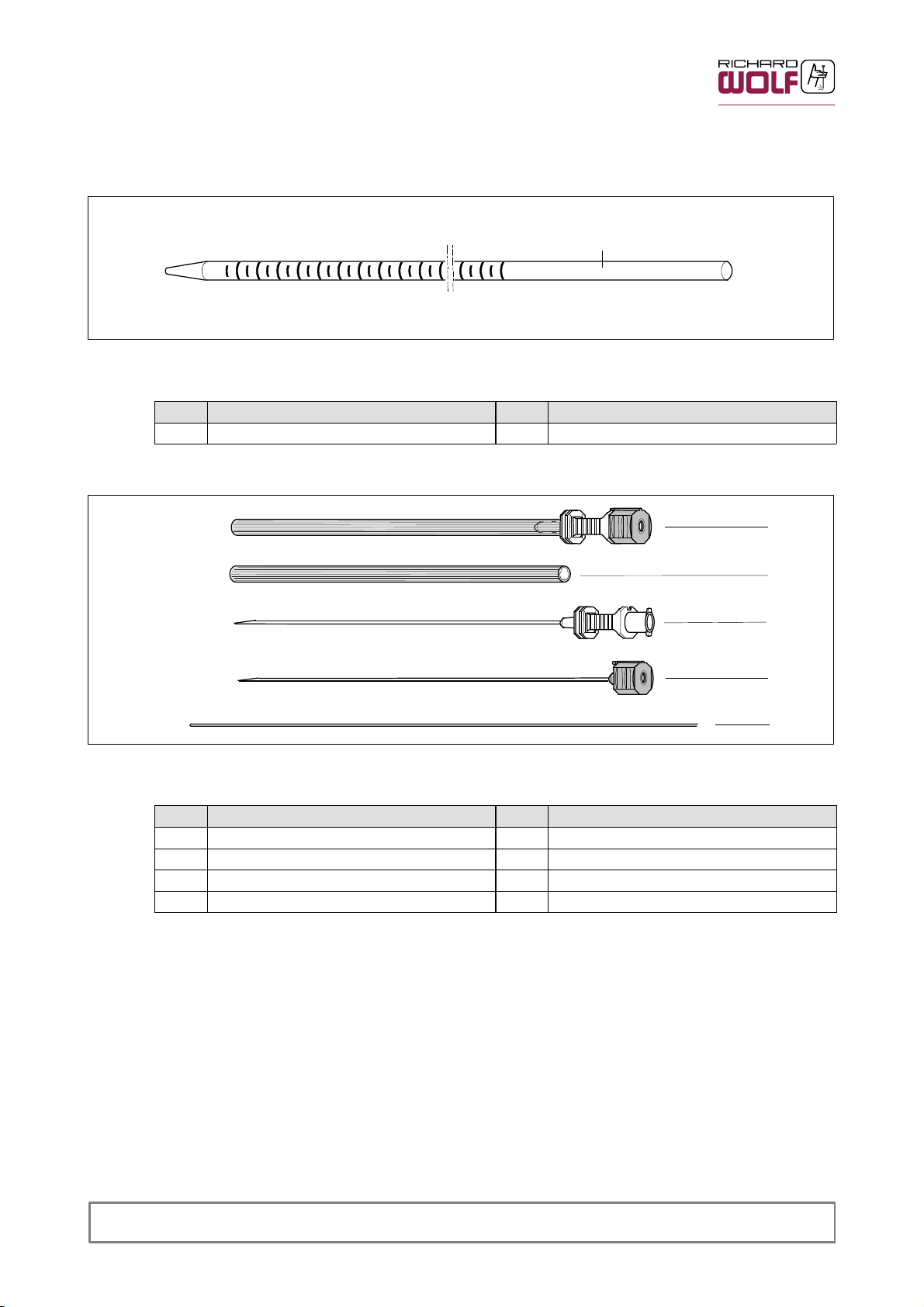
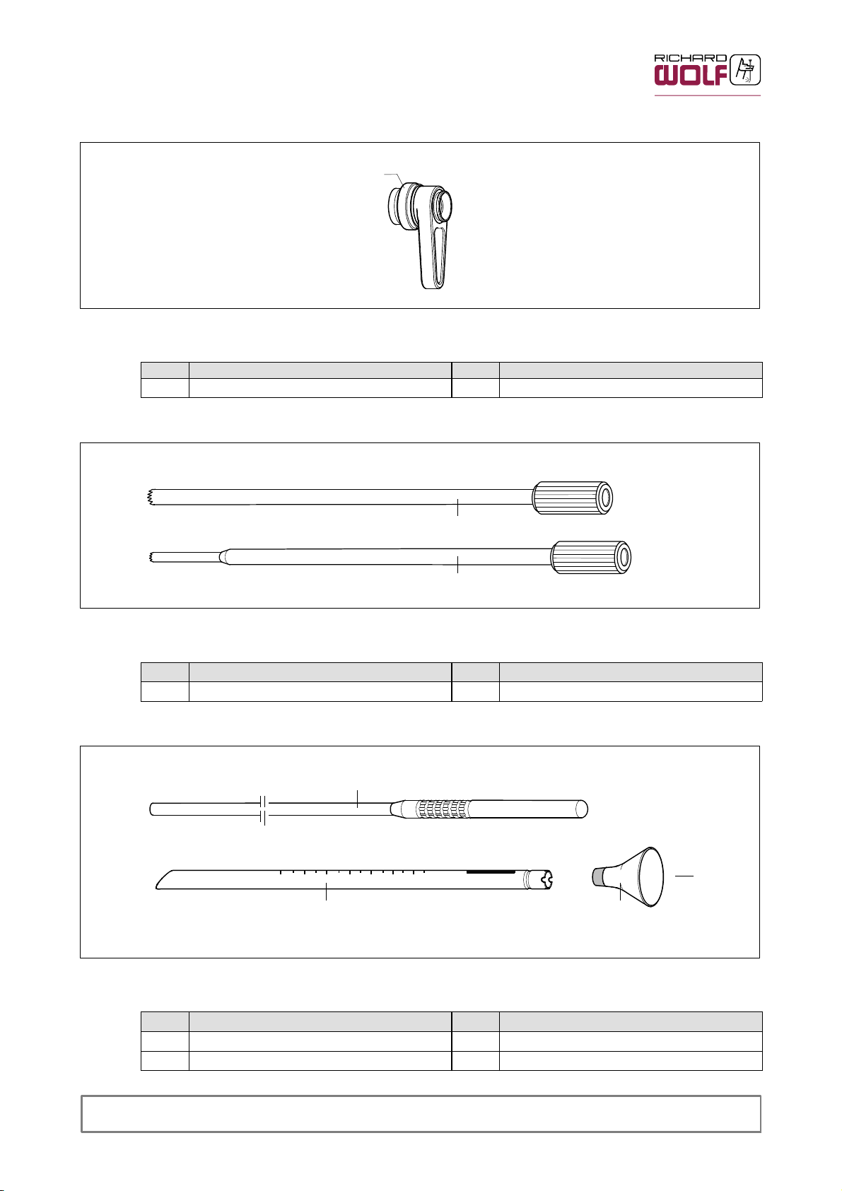
5.3.1 Positioning rod
Fig. 6
Legend and identification
Item Designation Item Designation
12 Positioning rod # Product no.
5.3.2 Disposable Spinal Cannula Set
12
#
13
13.1
Fig. 7
Legend and identification
Item Designation Item Designation
13 Disposable Spinal Cannula Set 14 Guide wire
13.1 Protection sleeve
13.2 Spinal cannula
13.3 Internal needle
For more information see instruction manual GA--B 175
13.2
13.3
14
7
GA-B 223
Page 13
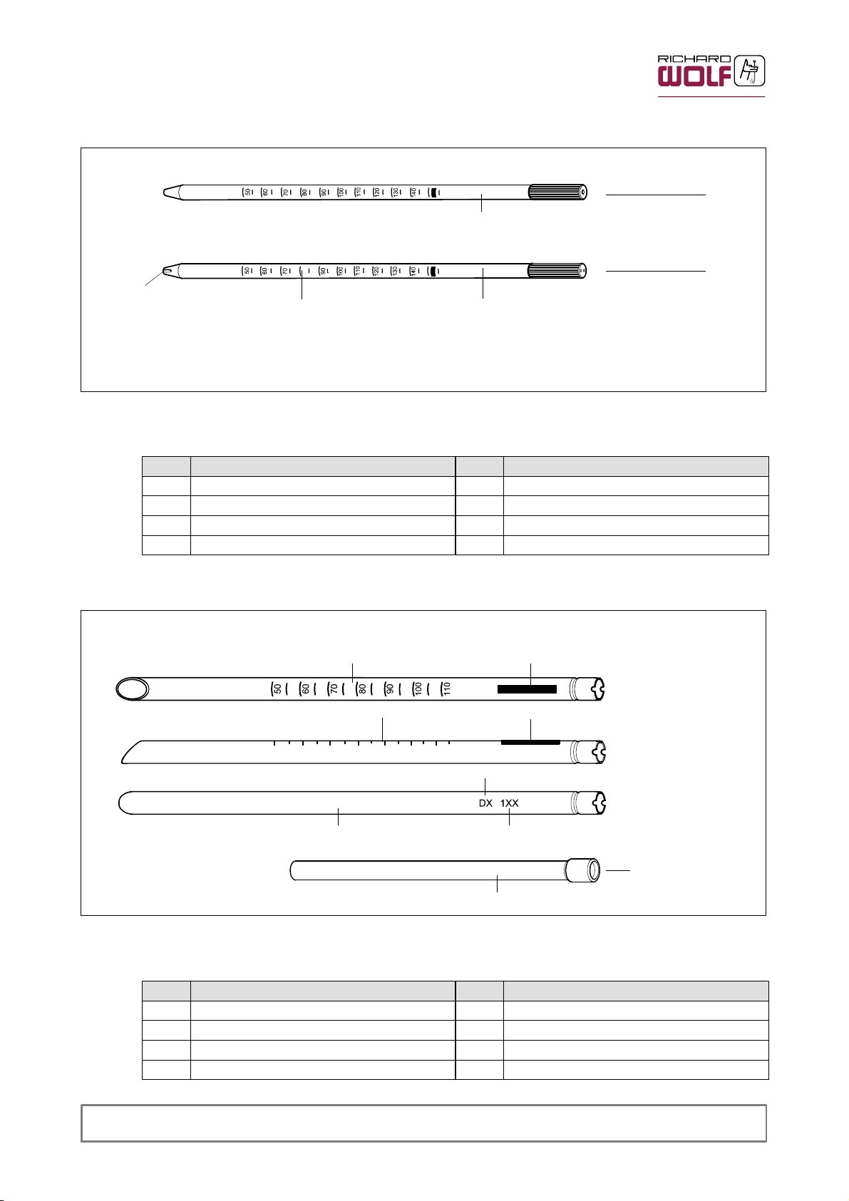
5.3.3 Dilators
15
15.1
#
15.2
15.2.1
Fig. 8
Legend and identification
Item Designation Item Designation
15 Dilators # Product no.
15.1 Dilator, single--channel * Scale, graduation in mm
15.2 Dilator, dual--channel
15.2.1 Eccentric bore for second channel
5.3.4 Working sleeve
*
#
16
*
*
16.1
16.1
Fig.9
Legend and identification
GA-B 223
##
#
###
#
Item Designation Item Designation
16 Working sleeves # Product no.
16.1 Identification of window position * Scale, graduation in mm
16.2 Extension sleeve ## External diameter in mm
### Length in mm
16.2
8
Page 14
5.3.5
Fig. 10
5.3.6 Trephines
Attachable handles
Legend and identification
Item Designation Item Designation
17 Attachable handle # Product no.
17
#
18
#
Fig. 11
Legend and identification
Item Designation Item Designation
18 Trephines # Product no.
5.3.7 Spongiosa pusher and funnel
Fig. 12
#
19
#
16
20
#
#
Legend and identification
Item Designation Item Designation
19 Spongiosa pusher
20 Spongiosa funnel # Product no.
9
GA-B 223
Page 15

5.4 Hand and auxiliary instruments
5.4.1 Anulotome / Dissector / Curette / Spoon / Rasp / Trocar / Face cutter
#
Fig. 13
21
22
23
24
25
26
27
Legend and identification
Item Designation Item Designation
21 Spoon 25 Dissector
22 Curette 26 Anulotome
23 Trocar 27 Face cutter
24 Rasp # Product no.
#
GA-B 223
10
Page 16

5.5 Forceps instruments, punches, scissors
28
#
28.1
28.2
29.2
29
#
30.1
30
30.2
29.2
30.3
30.5
30.4
31.1
32.2
32
32.3
30.6
29.1
32.1
31
31.2 31.3
#
33
33.1 33.2 33.3 33.4
Fig. 14
Legend and identification
Item Designation Item Designation
28--32 Handle versions
28 Suction forceps handle 30.5 Locking screw
28.1 Adjusting wheel 30.6 Thrust plate
28.2 Suction connector 31 Bone punch
Handle with ring--shaped grips with/
29
without finger support
29.1 Finger support 31.2 Sheath (tube)
29.2 Grip 31.3 Knurled nut
30 Intradiscal forceps, hinged 32 Forceps handle with strain relief
30.1 Luer--lock cap 32.1 Strain relief
30.2 Luer connector 32.2 Luer connector
30.3 Locking mechanism 32.3 Luer--lock cap
30.4 Deflection lever # Product no.
33 Jaw versions
33.1 Scissors 33.5 Micro rongeur, with two movable jaws
33.2 Grasping / holding forceps 33.6 Micro rongeur
33.3 Micro punch 33.7 Intradiscal grasping forceps, hinged
33.4 Micro bone punch / tubular sheath punch
33.7
33.6
31.1 Internal part (forceps actuator)
33.5
For more informations see instruction manuals GA--S 003 and BB-- S 003--1 / BB--S 003--2
11
GA-B 223
Page 17

5.6 Motorized instruments
5.6.1 Abraders
34
#
35
36
#
37
Fig. 15
Legend and identification
Item Designation Item Designation
34 Oval Burr, laterally hooded 36 Round Burr
35 Oval Burr, frontally hooded 37 Diamond Burr
# Product no.
For more information see instruction manual GA--A 202 and GA--A 238
5.6.2 Rotary blades
Fig. 16
Legend and identification
Item Designation Item Designation
38 Nucleus Resector
39 Nucleus Resector with Luer connector
39.1 Luer connector
39.2 Luer lock cap # Product no.
38
39
#
#
#
39.
1
39.2
For more information see instruction manual GA--A 202 and GA--A 238
GA-B 223
12
Page 18

5.7 HF / RF Instruments
5.7.1 Bipolar coagulations instruments and bipolar electrodes
40.1
41.1
41.2
41.3
41.4
41.5
41.6
*
40.2
40
#
41
#
*
#
42
Fig. 17
Legend and identification
Item Designation Item Designation
40 Coagulation instruments, bipolar 41.4 Stepped spherical electrode
40.1 Button Electrode 41.5 Ring electrode
40.2 Bipolar connection adapter, long 41.6 Stepped needle electrode
41 Bipolar electrodes 42 Bipolar needle by Biner
41.1 Hook electrode 43 Bipolar tweezers, bayonet--shaped
41.2 Needle electrode # Product no.
41.3 Spherical electrode *
For more informations see instruction manual GA--S 011
13
#
43
Identification of electrode insert on
packaging
GA-B 223
Page 19

5.7.2 Bipolar Micro Grasping Forceps
47
#
44
45
44
46
44.1
45
consisting of:
46.1
46.4
46.2
46
#
45.1
46.3
Fig. 18
Legend and identification
Item Designation Item Designation
44 Jaw insert 46 Spring handle
44.1 Jaws 46.1 Linking rod
45 Sheath 46.2 Receptable
45.1 Grip 46.3 Bipolar HF connector
For more information see instruction manual GA--B 210
GA-B 223
46.4 Handle guide
47 Rubber cap
# Product no.
14
Page 20

5.8 Accessories
5.8.1 Deflector
48
Fig. 19
Legend and identification
Item Designation Item Designation
48 Deflector # Product no.
5.8.2 Extractor instrument ”X--tractor”
49.2
#
49.349.1
49
#
50.1 50.150.2
Fig. 20
Legend and identification
Item Designation Item Designation
49 Handle 50 Clamping device
49.1 Recesses 50.1 Fastening pins
49.2 Spring 50.2 Fastening straps
49.3 Grip # Product no.
For more information see instruction manual GA--B 227.
##
50
**
* Size data
15
GA-B 223
Page 21

5.9 Packaging identification
Symbols Meaning
Attention, consult ACCOMPANYING DOCUMENTS
15
REF
SN
Order number
Lot identification number
Series number
Manufacturing date
Manufacturer
Units, pieces
Use--by date:
Do not reuse (for single use only)
Sterilized with ethylene oxide
25
Permissible temperature range
Keep away from heat
<60
<60%
Keep dry, atmospheric humidity below 60 %
Identification in conformity with Medical Devices Directive 93/42/EEC only valid if the product and/or
packaging is marked with this symbol. Products of category IIa and above, as well as sterile
products or products with measuring function of category I, are additionally marked with the code
number of the notified body (0124).
GA-B 223
16
Page 22

6Use
WARNING!
Do not reprocess disposable items!
Products marked ”disposable”, i.e. for single use only, have been designed
for only one use on or in a single patient.
If disposable items are reprocessed to be used again, product quality may
deteriorate, which will endanger the patient, user and others.
In this case the manufacturer can no longer guarantee the product’s safety
and performance.
CAUTION!
The products have only limited strength!
Exerting excessive force will cause damage, impair the function and there-
fore endanger the patient.
Immediately before and after each use, check the products for damage,
loose parts and completeness.
Ensure that no missing instrument parts remain in the patient.
Do not use products which are damaged, incomplete or have loose parts.
6.1 Preparation
Z Perform a visual check: section 7.1
Z Tighten the cold--light connector (1.5) (Fig. 1, page 3).
6.1.1 Assembling the endoscopes
Sealing cap adapter (Fig. 21)
Z Place the sealing membrane (1.7) into the locking collar.
Z Firmly tighten the sealing cap adapter (4).
Z Install the sealing cap (3).
Fig. 21
1.7
4 3
NOTE!
.
The sealing membrane (1.7) amd membrane valve (5.2) should be replaced after each use.
Membrane adapter (Fig. 22)
Z Place the sealing membrane (1.7) into the locking collar.
Z Firmly tighten the cone adapter (6).
Z Place the membrane valve (5.2) into sealing insert (5.1).
Z Screw the sealing insert (5.1) into connector (5.3).
Z Introduce the membrane adapter (5) in cone adapter (6) until the locking mech-
anism snaps into place.
NOTE!
.
If locking mechanism won’t engage, push release button (6.1) as far as it will go,
then repeat the procedure.
6.1
17
Fig. 22
1.7
6 5.3 5.2 5.1
GA-B 223
Page 23

Stopcock adapter (Fig. 23)
Z Place the sealing membrane (1.7) into the locking collar.
Z Firmly tighten the cone adapter (6).
Z Introduce the stopcock adapter (7) into cone adapter (6) until the locking mech-
anism snaps into place.
NOTE!
.
If locking mechanism won’t engage, push release button (6.1) as far as it will go,
then repeat the procedure.
Z Attachthesealingcap(3).
6.1
Fig. 24
2.1
Fig. 23
Endoscope A
For connecting endoscope A to objective lenses with C--mount thread, use the
plug--on eyepiece.
Z Attaching the plug--on eyepiece (2) (Fig. 24):
2
-- Unscrew the locking screw (2.1) turning in direction of arrow “a” as far as it
will go before you attach the eyepiece.
-- Install the plug--on eyepiece (2) and tighten the locking screw (2.1) in direction
of arrow “b”.
Fig. 25
Z Install the rubber caps (1.8).
Z Connect the irrigation tubes (A) to the irrigation stopcocks (1.10).
Z Connect the fiber light cable (B) to the cold--light connector (1.5) and to a suit-
able light source.
1.7
6 3
GA-B 223
Fig. 25
B
A
1.5
A
1.8
1.10
18
Page 24

Endoscope B (Fig. 26)
NOTE!
.
The eyepiece with eyecup of endocope B cannot be removed.
When mounting the irrigation adapter (8) make sure that you overcome the resist-
ance of the 0--rings and keep the irrigation adapter perfectly aligned.
Z Push the irrigation adapter (8) in direction of arrow as far as it will go.
' The irrigation adapter snaps into place.
Z Connect the irrigation tube (A) to the irrigation stopcock (8.1).
Z Connect the fiber light cable (B) to the cold--light connector (1.5) and to a suit-
able light source.
B
Fig. 27
1.15
1.5
A
8.1
8
1.5
xxxxx.xxxx
Fig. 26
Fig. 27
NOTE!
.
To achieve optimum light transmission the fiber bundle diameters of the endoscope and of the fiber light cable must be the same.
Possible consequences when using a fiber light cable with
' excessive diameter:
excessive heating at the coupling point with the endoscope
' insufficient diameter:
reduced light output
The model / type no. of the fiber light cable is an indicator for the suitable
fiber bundle diameter (1.15).
' The code number on the cold light connector (1.5) must be the same as
the last 2 digits to the right of the decimal point of the product number
(type number).
Exception: Fiber light cable 8061.933 has a fiber bundlediameter
of 3.5 mm.
19
CAUTION!
Intense heat due to high light energy!
Under unfavourable conditions the use of the high temperature resistant
fiber light cable 8063.353 can cause a temperature increase at the coupling
point between the fiber light cable and the endoscope.
Danger of burns for the user and risk of damage to the endoscope.
Reduce the light output, or use fiber light cable product no. 8061.xxx /
8062.xxx if necessary.
Z Carry out a function check: section 7.2
GA-B 223
Page 25

6.1.2 Attaching access instruments
Inserting working sleeve (16) into irrigation adapter (9) or attachable
handle (17)
NOTE!
.
The working sleeves (16) can be inserted in 4 working positions, i.e. in every 90
position.
Z Install the sealing cap (3) [not with attachable handle (17)] (Fig. 28).
3
Fig. 28
Fig. 29
Z Retract the locking sleeve (9.2) and hold it in the retracted position.
Z Insert working sleeve (16) in irrigation adapter (9).
Z Let go of the clamping sleeve (9.2).
Z Pull slightly to check that the connection is securely locked.
Z Connect the irrigation tube (A) to the irrigation stopcock (9.1)
' The clamping sleeve (9.2) returns to its home position.
[not with attachable handle (17)].
10
16
9
9.1
9.2
Fig. 29
Z Releasing the connection:
Retract the locking sleeve (9.2) and while holding it in this position, remove the
working sleeve (16).
Connecting suction connector (11) to suction tube (10).
Fig. 30
Z Plug the suction connector (11) under slight rotation into suction tube (10).
Z Connect the suction tube to the suction connector (11).
A
Fig. 30
GA-B 223
11
NOTE!
.
If on a short--term basis increased aspiration is required, the suction connector (11) can also be be directly attached to the distal end of the endoscope.
20
Page 26

6.1.3 Motorized instruments
NOTE!
.
In intadiscal use with the nucleus resector we recommend additional irrigation via
the luer connector or working sleeve.
Advantages:
' It improves cutting performance
' It facilitates the removal of tissue fragments
' It minimizes the risk of a possible clogging of the nucleus resectors
37.1
A
Fig. 31a
Fig. 31b
9.1
37
Irrigation through luer connector
Fig. 31a
Z Remove luer lock cap (37.2).
Z Connect irrigation tube (A) to luer connector (37.1) of nucleus resector (37).
IMPORTANT!
.
If the luer connector (37.1) is not required, it should be closed with the luer
37.2
38
9
A
lock cap (37.2) to avoid reduced suction power.
Irrigation through working sleeve
Fig. 31b
Z Install the sealing cap (3) as shown in Fig. 28.
Z Insert working sleeve (16) into irrigation adapter (9) and connect the irrigation
supply tube (A) to the luer connector (9.1) as shown in Fig. 29.
Z With the resector blade (38) connected to the shaver handpiece, insert the
resector blade (38) into the working sleeve (Fig. 31b).
Z Operate the resector blade (38) with irrigation supplied through the working
sleeve and suction connected to the shaver handpiece.
6.2 Additional notes and instructions for use
6.2.1 Light
IMPORTANT!
.
Use only products with type BF or CF applied parts in conjunction with the endoscope.
WARNING!
Intense heat due to high light energy!
Danger of inadvertent tissue damage
' due to insufficient distance between the light exit area and the tissue
' due to soiling / contamination in the light exit area
' when using high performance light projectors.
Do not touch the light exit area and avoid direct contact with the tissue.
Remove any soiling / contamination.
WARNING!
Fire hazard!
When placing the endoscope onto heat -sensitive flammable surfaces (dark
drapes etc.) the high light energy at the light exit area of the endoscope can
cause high temperatures or even ignition.
Store the endoscope at a safe place.
Switch off the light source if you do not use the endoscope for a prolonged
period of time.
21
GA-B 223
Page 27

6.2.2 Current
6.2.3 Image quality
6.2.4 Irrigation fluid
CAUTION!
Danger of burns!
Due to the high energy of the light source the cold light connector will be
hot when disconnecting it from the light source.
Burns may result from unintentional contact with the connector.
Do not touch the light connector, allow it to cool down.
WARNING!
Danger from electric shock!
Patient leakage currents can add up if the endoscope is combined with
powered endoscopic accessories.
Make sure that the combinations do not exceed the permissible patient leak-
age currents.
CAUTION!
Increased risk potential if the image is blurred!
Danger of injuring the patient.
Stop the intervention for safety reasons if the image is blurred.
Check the image quality of the endoscope before use (section 7.2).
CAUTION!
Irrigation fluid can be electrically conductive!
Depending on the application, a suitable low - conductivity irrigation fluid
must be selected by the user.
Do not use saline (NaCl) solution for HF applications.
6.2.5 Irrigation and suction power
CAUTION!
Determine the irrigation and suction rates!
Due to the differing anatomical conditions the irrigation and suction rates
cannot be quantified. The user must adapt these rates to the patient and to
the situation.
CAUTION!
In the case of motor - driven instruments!
Do not apply any suction during extradiscal application of the instruments!
To prevent inadvertent aspiration of other types of tissue (e.g. nerves),
suction is not permissible when the instruments are applied extradiscally.
GA-B 223
22
Page 28

6.2.6 HF application
Fig. 32
Follow the ”Notes and instructions on HF applications”, order no.: GA--S 002
as well as the HF device manufacturer’s instructions.
WARNING!
Danger of injury if the HF instrument is not visible through the scope!
Inadvertent tissue damage as well as damage to the distal end of the endo-
scope and instrument parts are possible.
Use HF instruments only within the scope of their specifications (voltage
strength, duty factor).
Activate HF instruments only after the part conducting HF current has be-
come fully visible through the scope and contact is made with the desired
area of use.
WARNING!
HF arcing!
Danger of injury due to incorrect HF application and insufficient distance
between parts conducting live HF current and other conductive parts.
Parts of HF instruments that conduct live HF current must maintain a safety
distance of at least 10 mm from the distal end of the endoscope or working
sleeve during activation (Fig. 32)
CAUTION!
Danger of burns due to leackage currents when using high- frequency current.
Burns on the surgeon’s eye or face may occur.
Use the endoscope only with the eyepiece (2) attached (Fig. 33).
Fig. 33
2
CAUTION!
Careful if HF output power is incorrectly selected!
Injuries to the patient as well as damage to the product are possible.
The power should be set on the basis of the surgeon’s experience / training
regarding the corresponding indication.
NOTE!
.
For determining the optimal power setting we recommend starting with a low
power setting.
23
GA-B 223
Page 29

6.3 Laser application
C
When applying a laser make sure you follow the laser device manufacturer’s instructions as well as the general regulations on the use of lasers.
Wear the required personal protection equipment.
CAUTION!
Do not work outside the scope’s field of view!
Inadvertent tissue damage as well as damage to the distal end of the endo -
scope and to instrument parts are possible.
Activate the laser only after
' the tip of the laser fiber is fully visible through the endoscope and
' the pilot beam makes contact with the intended area to be treated.
CAUTION!
High temperatures due to highly coherent laser beam!
The heat generated by the laser beam reduces the strength of instrument
parts.
Do not direct the laser beam at instrument parts, in particular not at plastic
parts.
Keep a safe distance.
CAUTION!
Highly coherent light beams!
Danger of eye injuries!
When using the product in conjunction with laser devices make sure you wear
adequate personal safety gear.
When using an ND -YAG laser while working through the endoscope under
direct view, use the additional filter attachment (C) (Fig. 34).
Keep a safe distance.
Fig. 34
6.3.1 Forceps instruments, punches, scissors
The following is a description of the special intradiscal grasping forceps:
NOTE!
.
For information about further forceps, punches and scissors, see GA--S003 and
B B -- S 0 0 3 -- 1 .
CAUTION!
Danger of injury as well as possible damage to the endoscope when
introducing or withdrawing instruments in open condition!
Inadvertent tissue damage, damage to the distal end of the endoscope as
well as loss of particles from the jaws are possible.
Introduce and withdraw the instrument only in closed condition and under
visual control (Fig. 35).
Fig. 35
GA-B 223
24
Page 30

CAUTION!
Danger of injury if the intradiscal grasping forceps is not used under visual
control!
Inadvertent manipulations may result in injuries.
Limit the use to the intradiscal space and ensure this by image converter
control if necessary.
Z Angling the jaw section (Fig. 36):
actuate either deflection lever (30.4) or thrust plate (30.6).
' The jaw section is deflected in upward direction.
30.4
30.6
Fig. 36
NOTE!
.
The jaws (29.7) can be rotated through 360
Z Changing the position of the jaws (Fig. 37):
-- Loosen locking screw (30.5) by turning as indicated by the arrow ”open”.
-- Turn the jaws (33.7) to the required position.
-- Tighten locking screw (30.5) by turning as indicated by the arrow ”close”.
' The jaws are locked in this position.
33.7
Fig. 37
to any position which suits the surgeon.
open
close
30.5
25
GA-B 223
Page 31

Z Locking the forceps handle (Fig. 38):
Push the handle grips together and turn the locking mechanism (26.3) in the
direction indicated by the arrow.
' The jaws (33.7) are closed and locked.
33.7
Fig. 38
NOTE!
.
The deflection lever can be mounted on the left or right--hand side.
IMPORTANT!
.
Deflection lever (30.4) is only functional if mounted parallel to the sheath.
Z Assembling the deflection lever (Fig. 39):
-- Insert the square section of the deflection lever in the square bore.
-- Push the deflection lever in the square bore as far as it will go.
' The deflection lever (30.4) clicks into place.
30.3
Fig. 39
30.4
GA-B 223
26
Page 32

Z Disassembly of deflection lever (Fig. 40):
-- Push onto the square of the deflection lever (30.4) from the opposite side until it
disengages from the square bore (Fig. 40a).
-- Remove the deflection lever (30.4) (Fig. 40b).
7 Checks
7.1 Visual check
Fig. 40a
Fig. 40b
30.4
Fig. 40
CAUTION!
Be careful if products are damaged or incomplete!
Injuries of the patient, user or others are possible.
Run through the checks before and after each use.
Do not use the products if they are damaged, incomplete or have loose parts.
Return damaged products together with any loose parts for repair.
Do not attempt to do any repairs yourself.
Z Check the instruments, in particular their distal areas, and the accessories for
' damage
' sharp edges
' loose or missing parts
' possible surface changes (e.g. corrosion)
' rough surfaces
' hairline cracks.
Z Replace sealing membrane (1.7) and membrane valve (5.2) after each use.
Z Replace any torn or damaged rubber caps (1.8 / 47), sealing caps (3) and O--
rings.
Z Check the jaws for defective cutting edges and corroded parts. (Fig. 41)
30.4
Fig. 41
27
CAUTION!
Danger of injury!
Check for surface changes, such as hairline cracks, around the hinge pin
(Fig. 41).
Caution if surface in the hinge area of the forceps is damaged.
The hinge pin can loosen.
Z Any lettering, labeling or identification necessary for the safe intended use
must be legible.
' Missing or illegible lettering, labeling or identifications leading to incorrect
handling and reprocessing must be reinstated.
GA-B 223
Page 33

7.2 Functional check
7.2.1 Endoscopes
Z Check image quality and light output in conjunction with the system compo-
nents.
Z Check the glass surfaces for any deposits.
' Deposits on the glass surfaces can cause a spotted or blurred field of view
and thus impair light transmission considerably.
' Wipe the glass surfaces with a swab soaked with alcohol (wood swab car-
rier, not metal or plastic), remove hard--to--remove deposits with instrument
cleaner.
35
Fig. 42
Z Check the light output without the system components.
Z Hold the distal end of the endoscope towards a light source.
' Broken fibers appear as black dots at the cold light connector. If approx. 30%
of the fibers are broken the light output is no longer sufficient (Fig. 43).
Fig. 43
7.2.2 Suction-- and irrigation instruments
Z Before use, check for proper irrigation flow, leak tightness and patency (free
passage) of the entire system.
Z Check the suction power of the working sleeve (16) with the irrigation adapter (9)
attached as well as that of the suction connector (11) and suction tube (10).
7.2.3 Forceps instruments, punches, scissors
Z Check the ratchet unit and handle grip locking mechanism.
Z Check the hinges.
Z Check the jaws for easy operation while you open and close them.
35
GA-B 223
28
Page 34

8 Reprocessing and maintenance
WARNING!
Creutzfeldt Jakob Disease!
If the patient is suspected of having the Creutzfeldt Jakob Disease (CJD) or a
variant of the Creutzfeldt Jakob Disease (vCJD) or the latter have been diagnosed, adequate measures must be taken to prevent possible transmission
to other patients, users and third parties.
For this purpose apply the country- specific reprocessing guidelines and
regulations.
8.1 Disassembly before cleaning
8.1.1 Endoscopes
1.5
Fig. 44
Z Unscrew the cold--light connector (1.5) (Fig. 44).
Fig. 45
4
1.7 3
Sealing cap adapter (Fig. 45)
Z Removethesealingcap(3).
Z Unscrew the sealing cap adapter (4).
Z Remove the sealing membrane (1.7).
NOTES!
.
Remove and replace the sealing membrane (1.7) and membrane valve (5.2)
after each use.
Membrane adapter (Fig. 46)
Z Unscrew the sealing adapter (5.1).
Z Remove the membrane valve (5.2).
Z Push the tab (6.1) and remove the membrane adapter (5.3).
Z Unscrew the cone adapter (6).
Z Remove the sealing membrane (1.7).
6.1
5.1
29
Fig. 46
1.7
6
5.3 5.2
GA-B 223
Page 35

Stopcock adapter (Fig. 47)
Z Removethesealingcap(3).
Z Push the tab (6.1) and remove the stopcock adapter (7).
Z Unscrew the cone adapter (6).
Z Remove the sealing membrane (1.7).
6.1 7
1.7
Fig. 47
Endoscope A
Z Remove the plug--on eyepiece (2) (Fig. 24, page 18).
Endoscope B
Z Push the locking tab (1.14) and remove the irrigation adapter (8) in direction of
arrow (Fig. 48).
6 3
8.1.2 Access instruments
35
1.14
8
Fig. 48
Working sleeve and irrigation adapter or attachable handle (17) (Fig. 49)
Z Separate the working sleeve (16) from the irrigation adapter (9) .
Z Remove the sealing cap [not with attachable handle (17)] (3).
16 9
9.2
3
Fig. 49
GA-B 223
30
Page 36

8.1.3 Forceps instruments, punches, scissors
ZUnscrew the luer--lock s
30.1
ZRemoving the deflection lever: see Fig. 40
Fig. 50
8.1.4 Motorized instruments
Z Remove the internal blade of the abraders (34) (35) and nucleus resectors (36)
(37) from the external blades.
8.2 Manual reprocessing
8.2.1 Endoscopes
Z Wet preparation at the point of use
Z Disassembly before cleaning: see section 8.1
Z Manual cleaning with an approved enzymatic cleaner.
8.2.2 Forceps instruments, punches, scissors
Z Wet preparation at the point of use
Z Disassembly before cleaning: see section 8.1
Z Manual cleaning with an approved enzymatic cleaner.
' Rinse out the intradiscal grasping forceps from the luer connector (30.2) us-
ing a cleaning gun (Fig. 51).
ealing cap (30.1) (Fig. 50).
8.2.3 Motorized instruments
37.2
37
Fig. 52
30.2
Fig. 51
Z Wet preparation at the point of use.
Z Disassembly before cleaning: Section 8.1
Z Manual cleaning with an approved enzymatic cleaner.
' Rinse out the nucleus resector with luer connector (37) from luer connector
port (37.2) with a cleaning gun (fig. 52)
31
GA-B 223
Page 37

8.3 Machine reprocessing
8.3.1 Endoscopes
.
.
Z Dry preparation at the point of use
Z Disassembly before cleaning: see section 8.1
Z Machine cleaning with an approved enzymatic cleaner.
Loading of reprocessing basket
Endoscope B
IMPORTANT!
Before machine reprocessing, preclean the rotatable irrigation adapter (8) manually.
IMPORTANT!
Before you place endoscope B into the reprocessing basket, install the rotatable
irrigation adapter (8) (section 6.1.1).
Endoscopes A and B (Fig. 53 / Fig. 54)
Z Screw on the supplied irrigation adapter (C).
' Before, clean the endoscope’s contact surfaces manually.
Z Place the parts used into the small items basket:
-- Rubber caps (1.8)
-- Sealing cap (3)
-- Sealing cap adapter (4)
-- Membrane adapter (5)
-- Cone adapter (6) and
-- New sealing membrane (1.7)
-- Snap--on eyepiece (2), only in the case of endoscope A
Z Place the cold--light connector (1.5) onto the corresponding holder.
Z Pass the irrigation tubes through the meshes, connect all connectors and open
the stopcocks (8.1) / (1.9) / (1.10).
IMPORTANT!
.
For machine cleaning do not place the stopcock adapter (7) into the reprocessing
basket but store it securely in the corresponding holders in the rinsing basket.
Endoscope B (Fig. 53)
4
1.7
= rinsing tube
1.5
8
B
C
Fig. 53
38044.411
GA-B 223
32
Page 38

Endoscope A (Fig. 54)
1.5
2
4
6
38044.111
= rinsing tube
B
Fig. 54
8.3.2 Forceps instruments, punches, scissors, nucleus resector with luer connector
Z Dry preparation at the point of use
Z Disassembly before cleaning: see section 8.1
Z Machine cleaning with an approved enzymatic cleaner.
' To prevent damage in the washer/disinfector, place the products in special
holders or in a reprocessing basket.
' Connect forceps / nucleus resector with luer connector (37) via luer connec-
tors (30.2 / 32.2), (37.1) to the washer/disinfector.
Z Oil all movable parts sparingly with instrument oil.
Wipe off/remove any excess oil.
8.4 Checks
Z Perform a visual check: see section 7.1
C
33
GA-B 223
Page 39

8.5 Assembly before sterilization
NOTE!
.
Before sterilization screw on the threaded connections only loosely:
' to allow a sufficient flow of sterilization medium.
' to prevent stress cracks.
Tighten all threaded connections before use.
IMPORTANT!
.
Do not screw on the luer lock caps (30.1 / 32.3), (37.2) to allow a sufficient flow
of sterilization medium.
Screw on the luer lock caps after sterilization and before use.
8.5.1 Endoscopes
Z Attach the cold--light connector (1.5) and screw it home (Fig. 1, page 3).
Z Oil all movable parts sparingly with endoscope oil.
Wipe off/remove any excess oil.
Endoscope B
Z Disassemble the rotatable irrigation adapter (8) (section 8.1.1) and oil the slid-
ing surfaces on the endoscope sparingly with instrument oil. Remove any excess oil.
Z Attach the rotatable irrigation adapter (8) see section 6.1.1.
Cone adapter (Fig. 55)
Z Place a new sealing membrane (1.7) into the locking collar.
Z Fasten the cone adapter (6) by means of the locking collar and tighten.
For better handling hold the locking collar with your thumb.
Fig. 55
5.3 5.2 5.1
1.7 6
Fig. 56
Sealing cap adapter (Fig. 21, page 17)
Z Place a new sealing membrane (1.7) into the locking collar.
Z Firmly tighten the sealing cap adapter (4).
Membrane adapter (Fig. 56)
Z Place a new membrane valve (5.2) into the sealing insert (5.1).
Z Screw the sealing insert (5.1) into the adapter (5.3)
GA-B 223
34
Page 40

8.6 Sterilization
Loading of reprocessing basket
Endoscopes A and B
Z Before sterilization, assemble endoscope B or A, as described under section
8.5.1.
Z Screw on the sealing cap attachment (4) only loosely.
Endoscope B (Fig. 57)
C
Fig. 57
Endoscope A (Fig. 58)
7
C
8
1.5
B
1.5
38044.411
4
38044.111
35
4
Fig. 58
Z For sterilization wrap the reprocessing basket/tray in compliance with the stan-
dards in your country or use a suitable sterilization container.
A
GA-B 223
Page 41

8.6.1 Steam sterilization
Z Steam sterilization at 132 C(270 F) using a Pre--Vac cycle at an exposure
time of 4 minutes with a 20 -- 30 minute dry time.
8.6.2 Gas sterilization
Z Gas sterilization using ethylene oxide (EtO).
8.6.3 Alternate sterilization methods
For possible alternate sterilization methods, refer to the Sterilization Guides posted
on our website, www.richardwolfusa.com.
8.6.4 Short Endoscope Tray, Item # 88090.0007
Loading the Tray
Z Assemble the short endoscope (B) and adapters as described under section 8.5.1.
Z Place the components into the reprocessing tray as shown in Fig. 59. Place loose
parts in the container at the center of the tray.
Z For sterilization, wrap the reprocessing tray in compliance with the standards in
your country, e.g., ISO 11607.
GA-B 223
Fig. 59
Steam Sterilization
Z Steam sterilization at 132 C(270 F) using a Pre-Vac cycle at an exposure
time of 4 minutes with a 20 -- 30 minute dry time.
36
Page 42

9 Technical data and order data
For additional information on the reprocessing, see Manual GA--J020 “Reprocessing of RICHARD WOLF Heat Stable Instruments”.
For technical data, order data and combinations of the following instruments see
”System overview VERTEBRIS lumbar--thoracic”, order no. BB--B 223.
Z Endoscopes, endoscopic accessories
Z Suction and irrigation instruments
Z Access instruments
Z Manual and auxiliary instruments
Z Motorized instruments
' see “Overview of motorized instruments” order no. BB--B 223--1.
For further information see the respective manuals.
9.1 Spare parts and accessories
Item Illustration Product no. Designation
2 8885.901 Snap--on eyepiece with eyecup
4 8792.452 Sealing cap adapter
5 8792.451 Membrane adapter
6 8791.751 Cone adapter
7 8791.951 Stopcock adapter
8 15461.034 Irrigation adapter, rotatable
-- 9500.113
5.2 89.103 Membrane valve
1.7 15 479.006 Sealing membrane
3 89.00 Sealing cap, black (10/pkg)
1.8 88.01 Rubber cap, red (10/pkg)
-- 887.00 Luer--Lock sealing cap
1.5 8095.00 Cold--light connector
O--rings serving as a seal between irrigation adapter
15461.034 and endoscope , 10/pkg
37
GA-B 223
Page 43

Item Illustration Product no. Designation
-- 200.532 Instrument oil
--
--
-- 64164.039
The products can be combined as required provided their relevant technical data and intended uses are observed. For the general overview please refer to the latest catalog sheets and brochures, or contact Richard
Wolf or your Richard Wolf representative.
--
--
38044.411 Reprocessing basket for endoscope B
38044.111 Reprocessing basket for endoscope A
Rinsing adaper for machine reprocessing in reprocessing
basket
10 Operating, storage, transport and shipping conditions.
Operating conditions
Storage, transport and shipping conditions
IMPORTANT!
.
Store sterile products in their original packaging until use.
Incorrect storage may lead to loss of sterility.
NOTE!
.
To prevent damage during transport or shipment of the products we recommend
using the original packaging material.
+10Cto+40C , 30% to 75% rel. humidity,
atmospheric pressure 700 hPa to 1060 hPa
-- 2 0 Cto+60C , 10% to 90% rel. humidity,
atmospheric pressure 700 hPa to 1060 hPa
11 Disposal of product, packaging material and accessories.
For the disposal observe the regulations and laws valid in your country.
' For further information please contact the manufacturer.
GA-B 223
38
Page 44

12 Warranty and Custome r Service
Richard Wolf guarantees ourinstrumentsto be free from any defectsin materialsand workmanshipunder
normal use and service for one year. Richard Wolf general terms and conditions may be found on the
back of our invoice.
Parts delivered separately by Richard Wolf are subject to all of the same general terms and conditions for
our products, including the limitations of warranty and liability.
All products should be returned to Richard Wolf for any necessary or desired repair or partreplacement.
No product repair or part replacement should be done other than by Richard Wolf unless the care and
instruction manual or other written information indicates that repair or part replacement is authorized. If
authorized,parts must be replaced onlyby partssupplied or specified by Richard Wolf, and productrepair
and part replacement must be done in strict conformance with Richard Wolf specifications and
instructions forrepair and part replacement, including post replacement testing and recalibration. Failure
to follow this requirement in any way can be dangerous to you, your personnel and your patients and
voids the warranty for the product repaired or the product in which the part was replaced and if the part
was supplied by Richard Wolf, for that part.
Delivery by Richard Wolf of technical documents such as circuit or other design diagrams does not
constitute authorization for product repair or part replacement. Richard Wolf instruments and other
products should never be modified or altered under any circumstances.
Contact Richard Wolf if you have any question (1) whether replacement of a part or a repair is authorized
by Richard Wolf, or (2) whether you have complete instructions and specifications forpart replacement or
repair.
These instructions do not attempt to cover all details or variations in equipment, nor to provide for every
possible contingency to be met in connection with installation, operation, or maintenance. Shouldfurther
information be required or should problems arise which are not covered sufficiently for the purchaser’s
purpose, the matter should be referred to Richard Wolf Medical Instruments Corporation.
Our national salesand service offices, as wellas our manufacturing facility, are located in Illinois. Trained
manufacturer’s representatives are located throughout the U.S. to serve you. For any questions
regarding these instruments, or to place an order, contact Richard Wolf c ustomer service department at
847-- 913--1113 or 800--323--WOLF (9653).
INSTRUMENT ORDERING POLICY
Richard Wolf reserves the right to make substitutions, if necessary, without prior notice.
REPAIR POLICY
Defective merchandise will be repaired or replaced at no charge to the customer, provided thecustomer
delivers such defective merchandise prepaid. Any repairs, maintenance or servicing of Richard Wolf
merchandise by anyone other than a factory authorized representative will render our warranty null and
void.
REPAIR SHIPMENTS
When returning your instrument for repair, we suggest that you prevent shipping damage to the
instrument by reusing the box that it was originally shipped in. Richard Wolf also recommends that the
instrument be insured for an amount to cover the cost of replacement.
IMPORTANT
For general safety and health reasons, Richard Wolf requires that you clean and sterilize all instruments
before returning them for repair. If instruments are received in an unsanitary condition, Richard Wolf will
clean and sterilize each instrument and add a $ 100.00 cleaning charge for each instrument requiring
cleaning.
39
GA-B 223
 Loading...