

Page 1

Cooktop Ventilation Hoods Installation Guide
Page 2

COOKTOP VENTILATION HOODS
Contents
3 Cooktop Ventilation Hoods
4 Specications
6 Installation
10 Troubleshooting
Features and specications are subject to change at any
time without notice. Visit wolfappliance.com/specs for the
most up-to-date information.
Important Note
To ensure this product is installed and operated as safely
and efciently as possible, take note of the following types
of highlighted information throughout this guide:
IMPORTANT NOTE highlights information that is especially
important.
CAUTION indicates a situation where minor injury or product
damage may occur if instructions are not followed.
WARNING states a hazard that may cause serious injury or
death if precautions are not followed.
IMPORTANT NOTE: Throughout this guide, dimensions in
parentheses are millimeters unless otherwise specied.
IMPORTANT NOTE: Save these instructions for the local
electrical inspector.
2 | Wolf Customer Care 800.222.7820
Page 3
COOKTOP VENTILATION HOODS
Product Information
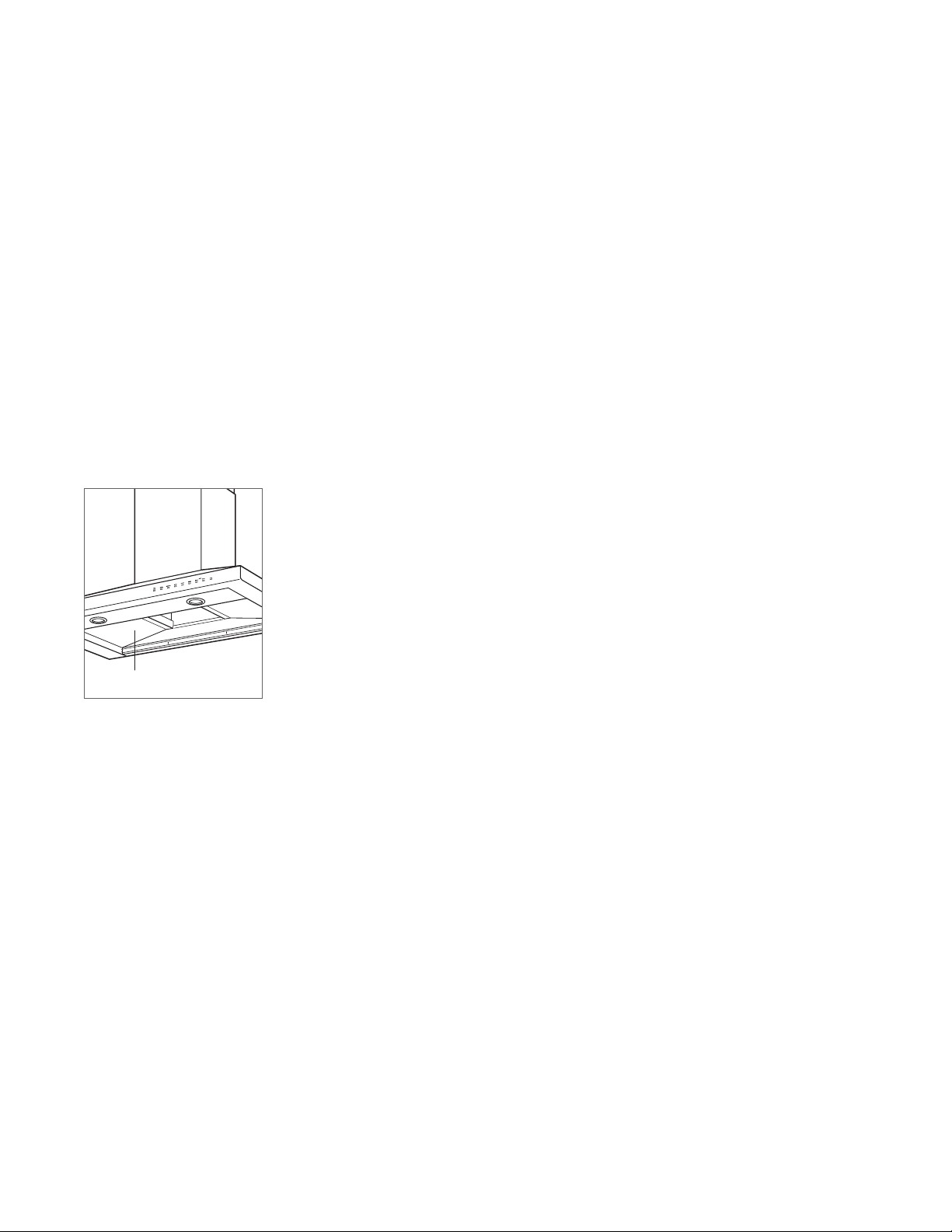
Important product information including the model and
serial number are listed on the product rating plate. The
rating plate is located under the left side of the hood, above
the lters (lters must be removed). Refer to the illustration
below.
If service is necessary, contact Wolf factory certied service with the model and serial number. For the name of
the nearest Wolf factory certied service or for questions
regarding the installation, visit the contact & support section
of our website, wolfappliance.com or call Wolf customer
care at 800-222-7820.
RATING PLATE
Rating plate location.
wolfappliance.com | 3
Page 4
SPECIFICATIONS
30"
Installation Requirements
Wolf cooktop ventilation hoods are recommended for use
with Wolf induction, electric and gas cooktops and integrated modules. For ranges and rangetops, a Wolf pro ventilation hood is recommended.
These hoods have a telescopic chimney ue. A ue extension is available through an authorized Wolf dealer.
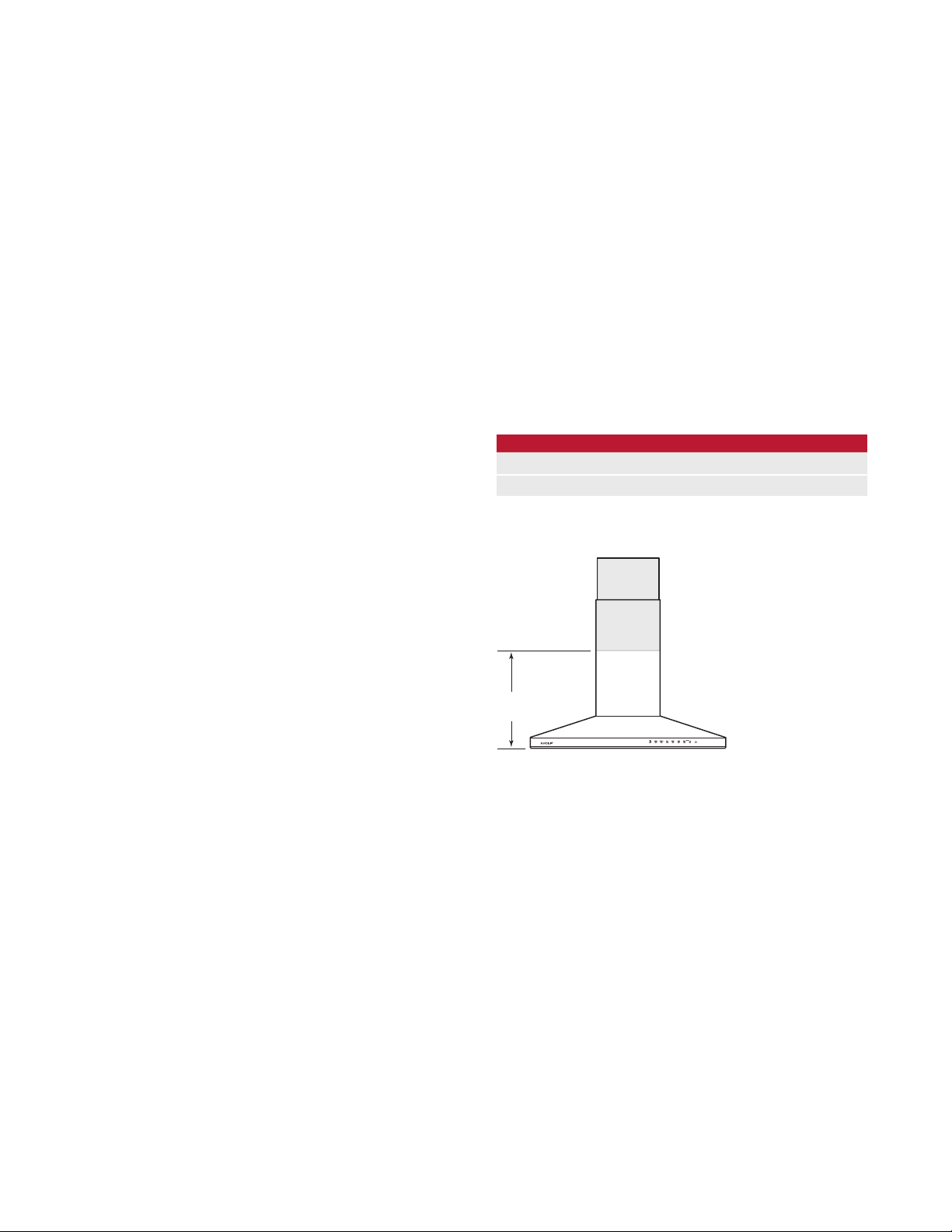
Installation of the cooktop hood should be 30"
(914) from the bottom of the hood to the countertop.
36"
Wall and island hoods require an internal, in-line or remote
blower assembly, avail able through an authorized Wolf
dealer. For local dealer information, visit the nd a showroom section of our website, wolfappliance.com.
Consult a qualied HVAC professional for specic installation and ducting applications.
(762) to
Electrical
Installation must be electrically grounded in accordance
with local codes or, in the absence of local codes, with the
National Electrical Code, ANSI/NFPA 70.
For wall hoods, locate the electrical supply within the
shaded area shown in the illustration below. Allow a
minimum 12"
(305) Romex
hoods, locate the electrical supply on the ceiling inside the
top of the hood. Allow a minimum 6'
connection. A separate circuit, servicing only this appliance
is required.
ELECTRICAL REQUIREMENTS
Electrical Supply grounded, 110/120 VAC, 60 Hz
Service 15 amp dedicated circuit
LOCATE
ELECTRICAL
WITHIN
SHADED AREA
®
wire for connection. For island
(1.8 m) Romex
E
®
wire for
18"
(457)
(762) TO 36" (914) BOTTOM EDGE TO COUNTERTOP
Electrical location—all wall hoods.
4 | Wolf Customer Care 800.222.7820
Page 5

SPECIFICATIONS
Ductwork
WARNING
To reduce the risk of re, use only metal ductwork.
6" (152) round, rigid metal duct is recommended for cooktop
ventilation hoods.
A straight, short run is most effective and will ensure proper
operation. For best results, the duct run should not exceed
(15 m). For runs exceeding 50' (15 m), a higher CFM
50'
blower may be required to maintain proper air ow and
performance. A remote blower installed on a short duct run
may increase the potential for noise.
Internal and in-line blowers require a roof or wall cap (not
provided). Connect ductwork to the cap and work back
towards the hood. Use sheet metal screws and aluminum
tape or high temperature duct tape to seal joints between
ductwork sections.
Wall and island hoods include a backdraft damper. Local
codes may require the use of an additional backdraft and/or
make-up air damper. Contact your local HVAC professional
for specic requirements.
A make-up air damper is available through an authorized
Wolf dealer. For local dealer information, visit the nd a
showroom section of our website, wolfappliance.com.
wolfappliance.com | 5
Page 6
INSTALLATION
Installation
WALL HOOD
If an internal blower is being installed, install the blower prior
to mounting the hood. Refer to page 8 for internal blower
installation.
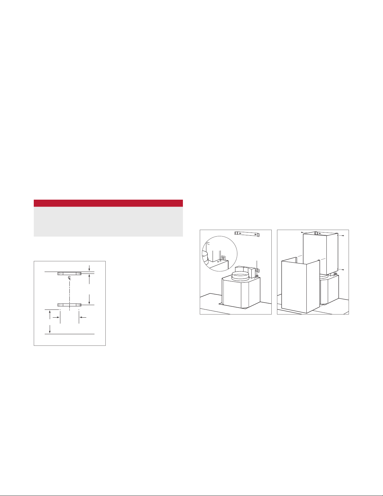
1 Mark the center line for location of two mounting holes
using dimensions shown in the chart and illustration
below. Additional wall framing is recommended in this
location. If wall framing is not available, the use of wall
anchors is recommended. Install the mounting screws
1
so there is approximately
/4" (6) gap between the screw
head and wall. Position the two mounting brackets for
the chimney ue, then install using two mounting screws
per bracket. Refer to the illustration below.
MOUNTING LOCATION
SCREW LOCATION A
Black Hood 123/4" (324)
Stainless Hood 163/8" (416)
Glass Hood 129/16" (319)
CEILING
3
(19)
/4
"
2 Place the mounting tabs over the mounting screws. Use
the leveling adjustment screws to ensure the hood is
level. Refer to the illustration below.
3 Mount the electrical plate to the wall using screws
provided.
4 Place the backdraft damper on the round discharge then
install 6" (152) round metal ducting (not provided) to the
damper and seal with aluminum tape.
5 Make wiring connections. Refer to page 9.
6 Once wiring connections are complete, secure the upper
chimney ue to the mounting brackets using screws
provided. Refer to the illustration below. Place the lower
chimney ue over the upper, then lower until it rests on
the hood.
LEVELING
SCREW
MOUNTING
TA B
1
/8
9
(232)
A
BOTTOM OF HOOD
Mounting location.
1
/16
17
"
(433)
"
Mount and level hood.
Install telescopic ue.
6 | Wolf Customer Care 800.222.7820
Page 7
INSTALLATION
8
5
/8
"
(219)
ELECTRICAL
LOCATION
11"
(279)
UPPER
FLUE
Installation
ISLAND HOOD
If an internal blower is being installed, install the blower prior
to mounting the hood. Refer to page 8 for internal blower
installation.
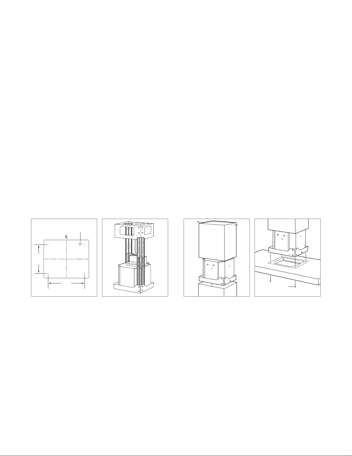
1 Mark the center line for location of four mounting holes
using dimensions shown in the illustration below. Use
the template provided to mark the mounting support
1
locations, then use a 1
/4" drill bit to create a hole for the
electrical power supply.
2 Place four mounting screws into the ceiling, then posi-
tion the support frame on those screws. Once the support frame is in place, tighten screws.
3 Determine the desired height of the support frame and
adjust the height by removing four screws. Once the
desired height is achieved, reinstall and tighen screws.
4 Place the damper on the support frame then attach duc-
twork to the damper.
5 Slide the upper chimney ue onto the support frame and
attach to the support frame using screws provided. Refer
to the illustration below. Slide the lower chimney ue
over the upper and temporarily secure in this position
using adhesive tape.
6 Raise the hood to the support frame and connect the
hood to the support frame with four screws provided.
Refer to the illustration below.
7 Make wiring connections. Refer to page 9.
8 Once wiring connections are complete, remove the
adhesive tape securing the lower chimney ue, then
lower until it rests on the hood.
MOUNTING
SCREW
Mounting location.
Support frame.
Install telescopic ue.
Mount hood.
wolfappliance.com | 7
wolfappliance.com | 7
Page 8
INSTALLATION
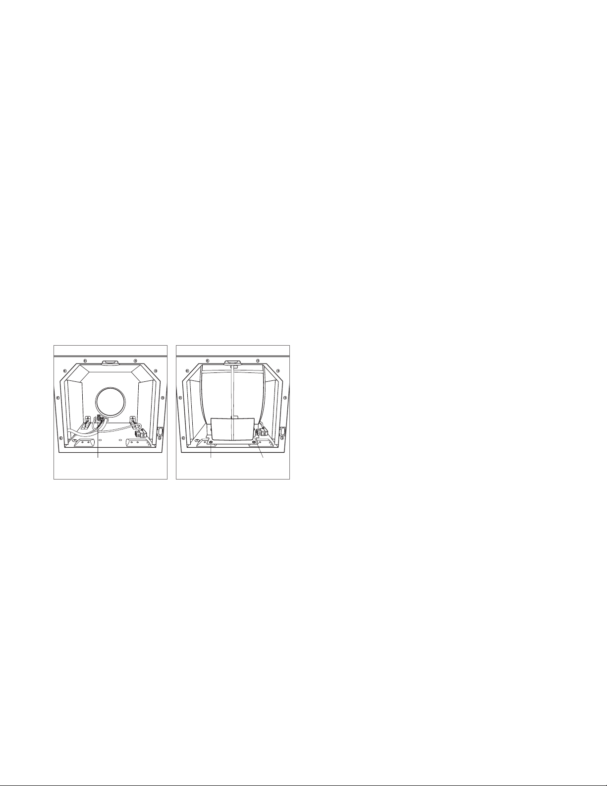
Installation
INTERNAL BLOWER
If an internal blower will be used, it should be installed prior
to mounting the hood. Refer to additional instructions provided with the internal blower.
1 Insert the three-prong plug from the blower wire into the
hood receptacle. Refer to the illustration below.
2 Insert the blower by aligning the round discharge on the
blower with the discharge on the hood.
3 Insert the plug from the blower wire into the receptacle
on the blower. Refer to the illustration below.
4 Secure the blower to the hood using the two mounting
screws provided.
RECEPTACLE
Hood receptacle.
MOUNTING
SCREW
Mount blower.
RECEPTACLE
8 | Wolf Customer Care 800.222.7820
Page 9
MOVE WIRES
HERE
COVER
INSTALLATION
KNOCKOUT
COVER
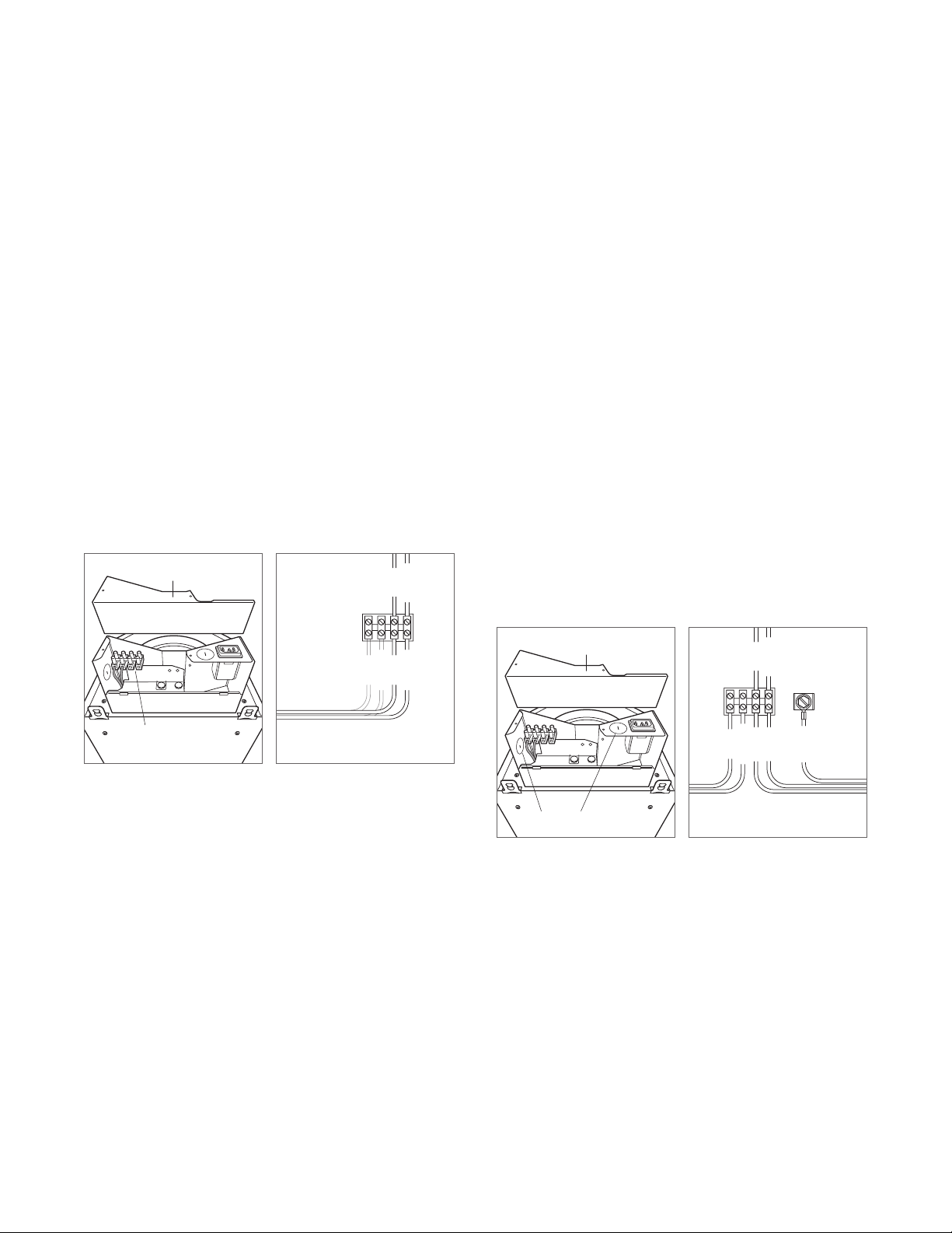
Wiring Connections
INTERNAL BLOWER WIRING
1 Remove the top cover of the electrical box by extracting
two screws. Refer to the illustration below.
2 Remove the two existing wires from the left side of
the terminal block and transition them to the right and
secure. Refer to the illustration below.
3 Place all wiring connections inside the electrical box and
reinstall the cover. Make sure all wires are secure and not
pinched between the cover and electrical box.
4 Secure the junction box supplied with the hood to the
wall, then connect to the (Romex
®
) power supply from
the home. Once the connection has been made, insert
the plug into the receptacle on the hood.
BLUE
BROWN
BLUE
BLUE
BROWN
BROWN
IN-LINE / REMOTE BLOWER WIRING
1 Remove the top cover of the electrical box by extracting
two screws. Refer to the illustration below.
2 Remove one of the round knockouts using a at blade
screwdriver.
3 Insert Romex
®
wire from the blower through the
knockout and secure using an approved cord stain relief.
4 Connect white to blue, black to brown and green to
ground. Refer to the illustration below.
5 Place all wiring connections inside the electrical box and
reinstall the cover. Make sure all wires are secure and not
pinched between the cover and electrical box.
6 Secure the junction box supplied with the hood to the
support frame, then connect to the (Romex
®
) power
supply from the home. Once the connection has been
made, insert the plug into the receptacle on the hood.
BLUE
BROWN
GROUND
Wiring location.
TO INTERNAL
BLOWER
Internal blower wiring.
Wiring location.
BLUE
WHITE
BLACK
BROWN
GREEN
TO IN-LINE/REMOTE
BLOWER
In-line / remote blower wiring.
wolfappliance.com | 9
Page 10

TROUBLESHOOTING
Troubleshooting
IMPORTANT NOTE: If the ventilation hood does not operate
properly, follow these troubleshooting steps:
• Verify electrical power is supplied to the ventilation hood.
• Verify proper wiring connections.
• If the ventilation hood does not operate properly, contact
Wolf factory certied service. Do not attempt to repair
the hood. Wolf is not responsible for service required to
correct a faulty installation.
10 | Wolf Customer Care 800.222.7820
Page 11

Wolf, Wolf & Design, Wolf Gourmet, W & Design and the color red as applied to knobs are registered trademarks and service marks of Wolf Appliance, Inc. Sub-Zero, Sub-Zero
& Design, Dual Refrigeration, The Living Kitchen, Great American Kitchens The Fine Art of Kitchen Design, and Ingredients are registered trademarks and service marks of
Sub-Zero, Inc. (collectively, the “Company Marks.”) All other trademarks or registered trademarks are property of their respective owners in the United States and other countries.
Page 12

WOLF APPLIANCE, INC. P.O. BOX 44848 MADISON, WI 53744 WOLFAPPLIANCE.COM 800.222.7820
000000 REV-A 4/2014
 Loading...