

Page 1
CUP WARMING DRAWER
INSTALLATION GUIDE
GUÍA DE INSTALACIÓN
GUIDE D’INSTALLATION
GUIDA ALL’INSTALLAZIONE
INSTALLATIONSANLEITUNG
INSTALLATIEHANDLEIDING
Page 2
CUP WARMING DRAWER
Contents
2 Cup Warming Drawer
3 Specications
4 Installation
5 Troubleshooting
Features and specications are subject to change at any
time without notice.
Important Note
To ensure this product is installed and operated as safely
and efciently as possible, take note of the following types
of highlighted information throughout this guide:
IMPORTANT NOTE highlights information that is especially
important.
CAUTION indicates a situation where minor injury or product
damage may occur if instructions are not followed.
WARNING states a hazard that may cause serious injury or
death if precautions are not followed.
IMPORTANT NOTE: Save these instructions for the local
electrical inspector.
SAVE THESE INSTRUCTIONS
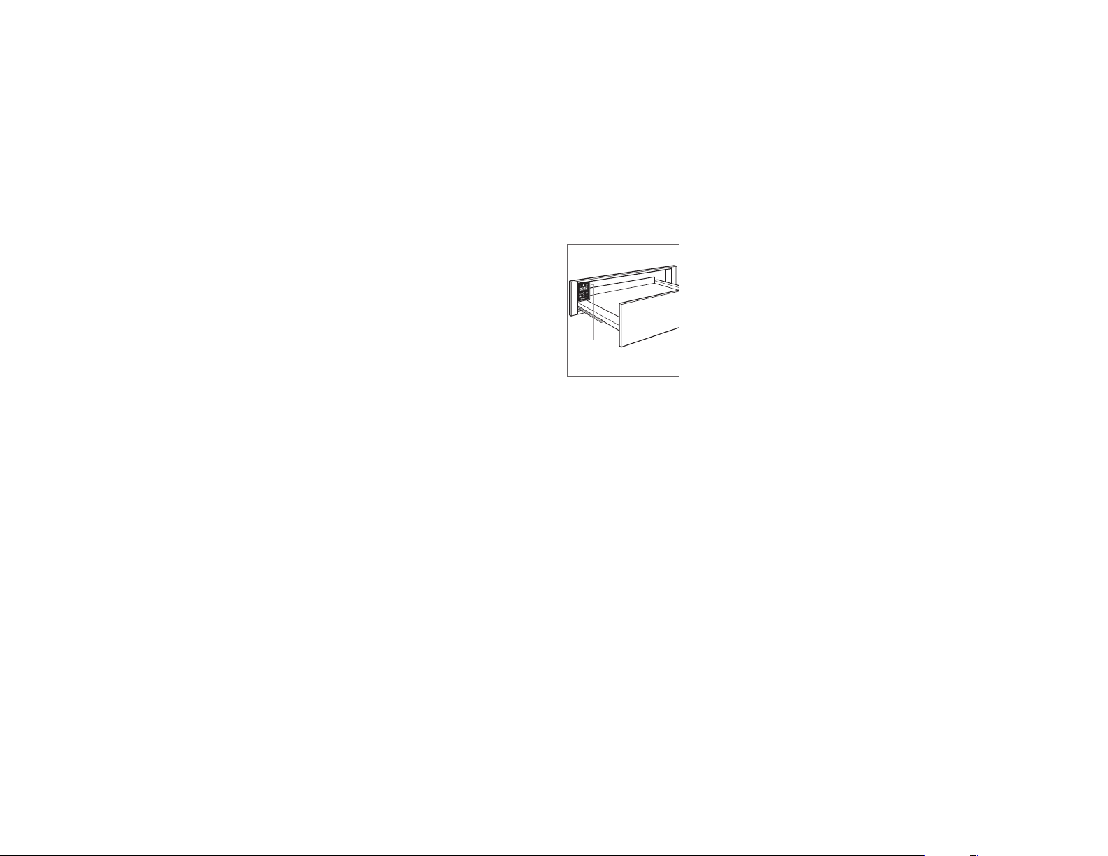
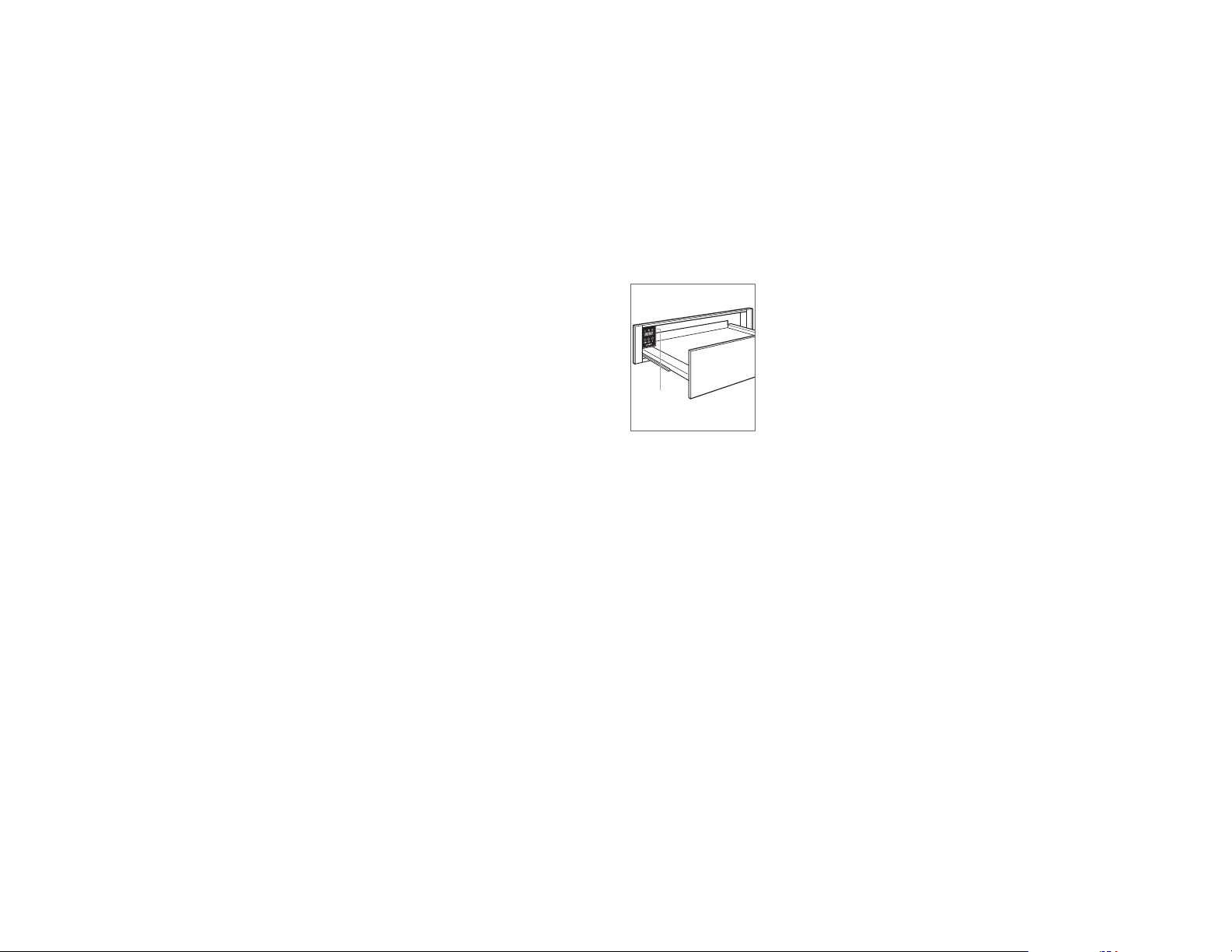
Product Information
Important product information including the model and
serial number are listed on the product rating plate. The
rating plate is located on the right side of the control panel.
The drawer must be open to view the rating plate. Refer to
the illustration below.
If service is necessary, contact Wolf factory certied service
with the model and serial number.
RATING
PLATE
Rating plate location.
2 | English
Page 3
SPECIFICATIONS
SIDE
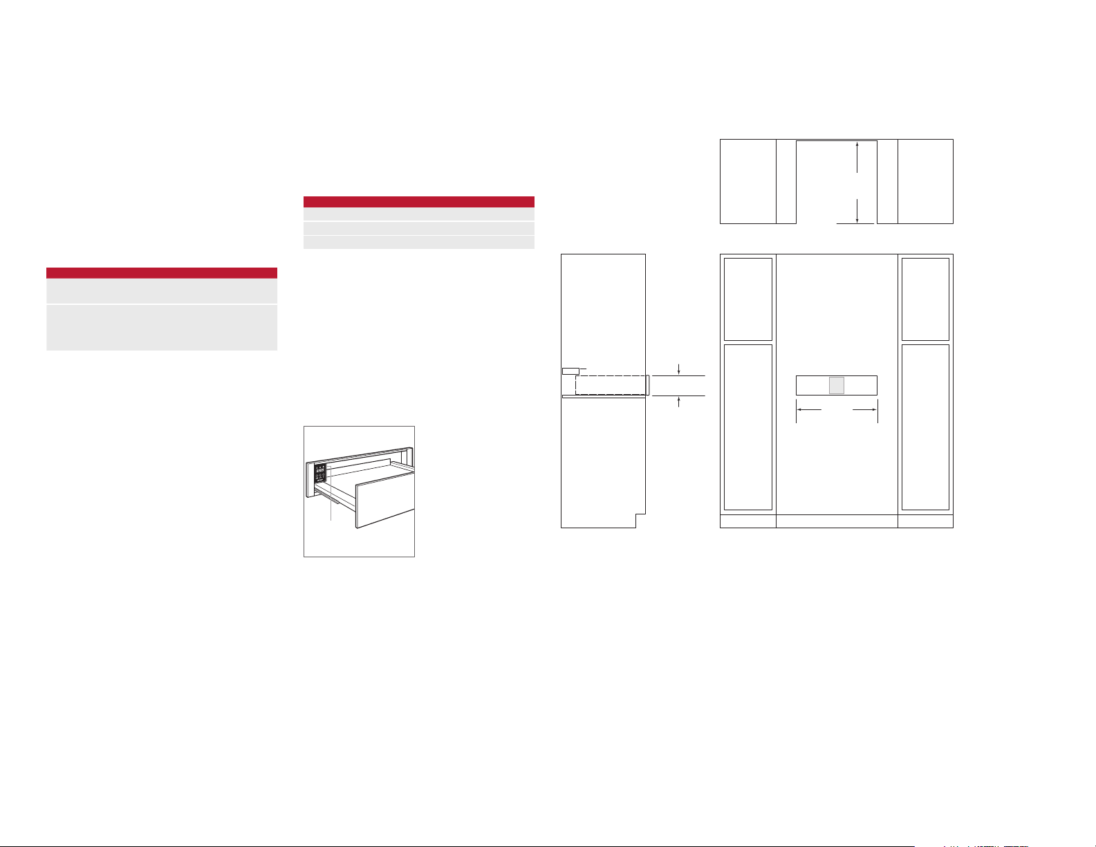
NOTE: Dashed line represents profile of unit.
Installation Requirements
The cup warming drawer can be installed in a standard or
ush inset application. Finish the edges of the opening.
They may be visible when the drawer is open.
For standard installations, face trim will overlap stiles and
rails. Refer to the chart below.
For ush inset installations, a minimum 3 mm reveal is
required on all sides. To ensure consistent reveals, each
corner of the opening must be exactly 90°.
An anti-tip block must be installed to prevent the cup
warming drawer from tipping forward when opened.
INSTALLATION REQUIREMENTS
BASE SUPPORT MIN
Cup Warming Drawer 34 kg
TRIM OVERLAP
Top 0 mm
Bottom 0 mm
Sides 18 mm
COMBINATION INSTALLATION
To install a cup warming drawer below a coffee system,
one opening for both units must be specied. To achieve
the minimum reveal between units, place the coffee system
support rails on top of the cup warming drawer, then secure
the rails to the sides of the cabinet. Any material between
the units will increase the horizontal reveal.
Installation of an anti-tip block is not necessary when the
cup warming drawer is installed below a coffee system.
Electrical
Installation must comply with all applicable electrical codes
and be properly grounded (earthed).
Locate the electrical supply as shown in the illustrations on
the following pages. A separate circuit, servicing only this
appliance is required.
ELECTRICAL REQUIREMENTS
Electrical Supply 220-240 VAC, 50/60 Hz
Service 420W
Power Cord .9 m
IMPORTANT NOTE: Connection of this appliance should be
through a fused connection unit or a suitable isolator, which
complies with national and local safety regulations. The
on/off switch should be easily accessible after the appliance has been installed. If the switch is not accessible after
installation (depending on country) an additional means of
disconnection must be provided for all poles of the power
supply. When switched off there must be an all pole contact
gap of 3 mm in the isolator switch. This 3 mm contact disconnect gap must apply to any isolator switch, fuses and/or
relays according to EN60335.
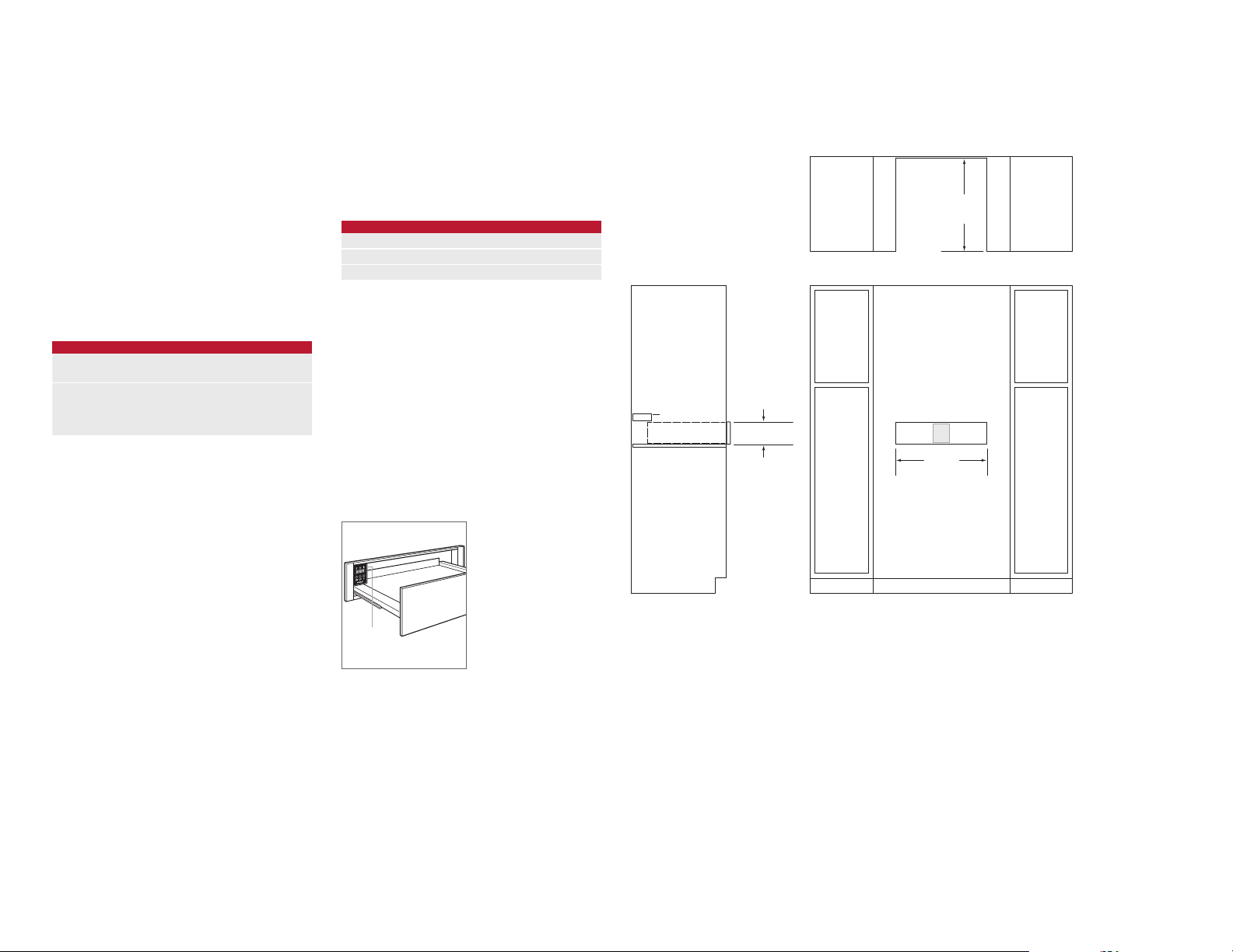
Cup Warming Drawer
STANDARD INSTALLATION
ANTI-TIP BLOCK
OPENING HEIGHT
140 mm
572 mm
OPENING
DEPTH
TOP VIEW
E
562 mm
OPENING WIDTH
RATING
PLATE
Rating plate location.
VIEW
FRONT VIEW
wolfappliance.com | 3
Page 4
SPECIFICATIONS
INSTALLATION
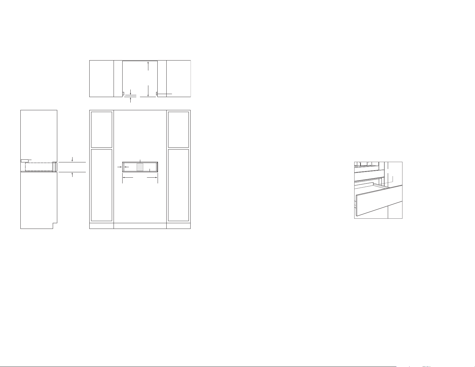
Cup Warming Drawer
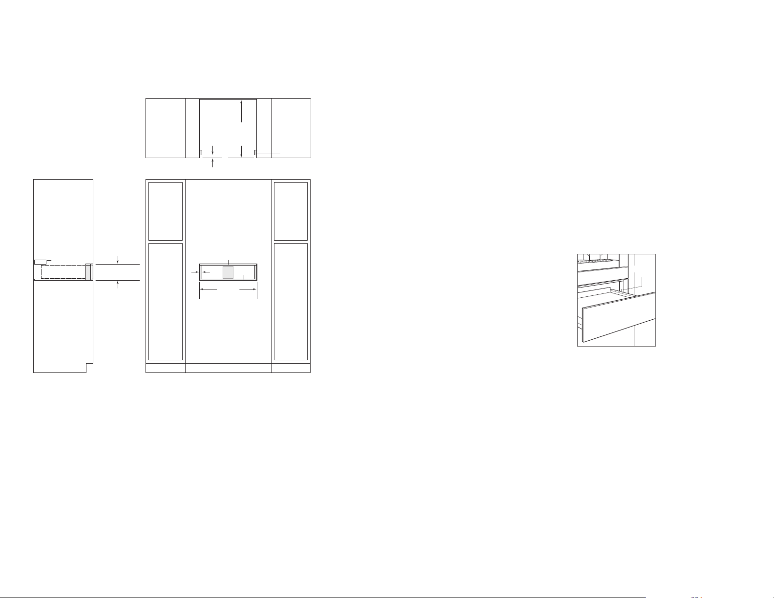
FLUSH INSET INSTALLATION
ANTI-TIP BLOCK
FLUSH INSET
146 mm
HEIGHT
597 mm
FLUSH
INSET
DEPTH
25 mm
TOP VIEW
3 mm
21
3 mm
E
mm
603 mm
FLUSH INSET WIDTH
FINISHED
CLEATS*
Preparation
Remove and recycle packing materials. Do not discard the
package containing two screws provided for installation.
If the cup warming drawer is installed independently, install
an anti-tip block against the rear cabinet wall. Verify screws
are adequately secured and do not penetrate electrical
wiring or plumbing.
Installation
1 Turn power off to the electrical outlet.
2 Slide the left corner of the cup warming drawer into the
opening. If the electrical supply is located in the opening,
plug the power cord into the receptacle. If it is located in
an adjacent cabinet, guide the power cord through the
hole in the cabinet wall. Coil excess power cord behind
or beside the unit.
3 Slide the unit back into the opening until the trim
meets the cabinet front. Avoid pinching the power cord
between the unit and cabinet wall.
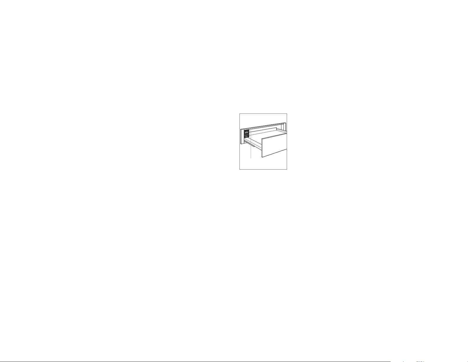
4 Open the cup warming drawer to full extension. Drill a
pilot hole in each mounting hole, located at the front, on
each side of the unit. Refer to the illustration below.
5 Mount the unit using two screws provided.
6 Turn power back on to the electrical outlet.
MOUNTING
HOLE
Mounting hole.
*Will be visible and should be finished to match cabinetry.
NOTE: Dashed line represents profile of unit.
4 | English
FRONT VIEWSIDE VIEW
Page 5

TROUBLESHOOTING
Troubleshooting
IMPORTANT NOTE: If the cup warming drawer does not
operate properly, follow these troubleshooting steps:
• Verify electrical power is supplied to the cup warming
drawer.
• Verify proper electrical connections.
• If the warming drawer does not operate properly, contact
Wolf factory certied service. Do not attempt to repair
the cup warming drawer. Wolf is not responsible for
service required to correct a faulty installation.
Sub-Zero, Sub-Zero & Design, Sub-Zero & Snowake Design, Dual Refrigeration, The Living Kitchen, Great American Kitchens The Fine Art of Kitchen Design, Wolf, Wolf & Design, Wolf Gourmet, W & Design, red colored knobs, Cove, and Cove & Design, are registered trademarks and service marks of Sub-Zero Group, Inc. and its subsidiaries.
All other trademarks are property of their respective owners in the United States and other countries.
wolfappliance.com | 5
Page 6
CAJONES CALENTADORES DE TAZAS
Índice
2 Cajones calentadores de tazas
3 Especicaciones
4 Instalación
5 Localización y solución de problemas
Las características y especicaciones están sujetas a
cambios sin previo aviso.
Nota importante
Para garantizar que este producto se instala y funciona de
la forma más ecaz y segura posible, tenga en cuenta la
información que se destaca en esta guía:
Cuando aparece
que resulta especialmente importante.
PRECAUCIÓN indica una situación en la que se pueden
sufrir heridas leves o provocar daños al producto si no se
siguen las instrucciones.
AVISO indica el peligro de que se produzcan heridas graves
o incluso la muerte si no se respetan las precauciones.
NOTA IMPORTANTE: conserve estas instrucciones para el
inspector eléctrico local.
NOTA IMPORTANTE, se resalta información
GUARDE ESTAS
INSTRUCCIONES
Información sobre el producto
En la placa de datos del producto encontrará información
importante, incluyendo el modelo y el número de serie. La
placa de datos está ubicada en el lateral derecho del panel
de control. El cajón debe estar abierto para ver la placa de
datos. Observe la siguiente ilustración.
Si necesita recurrir a un servicio técnico, póngase en
contacto con un servicio técnico autorizado de Wolf con el
número de serie y modelo.
PLACA DE
DATOS
Ubicación de la placa de datos.
2 | Español
Page 7
ESPECIFICACIONES
VIST
NOTA: las líneas discontinuas representan el perfil de la unidad.
Requisitos de instalación
El cajón calentador de tazas puede instalarse en una aplicación
estándar o empotrable. Remate los bordes de la cavidad, pues
son áreas que pueden resultar muy visibles al abrir el cajón.
Para instalaciones estándar, el contramarco frontal irá
superpuesto sobre los raíles y montantes. Observe la tabla
que aparece más abajo.
Para instalaciones empotrables, es necesario un margen
mínimo de 3 mm en todos los lados. Para garantizar unos
márgenes consistentes, cada esquina de la cavidad debe
tener exactamente 90º.
Debe instalar un bloque anti-vuelco para evitar que el
cajón calentador se incline hacia adelante mientras se abre
cuando está cargado.
REQUISITOS DE INSTALACIÓN
SOPORTE DE LA BASE MÍN.
Cajón calentador de tazas 34 kg
SUPERPOSICIÓN DEL MARCO
Superior 0 mm
Inferior 0 mm
Lados 18 mm
INSTALACIONES COMBINADAS
Para instalar un cajón calentador de tazas debajo de un
sistema de café, debe especicarse una cavidad para ambas
unidades. Para obtener el margen mínimo entre las unidades,
coloque los rieles de soporte del sistema de café en la parte
superior del cajón calentador de tazas y, a continuación, je
los rieles en los lados del armario. Cualquier material que
exista entre las unidades aumentará el margen horizontal.
No será necesario instalar un bloque anti-vuelco si el cajón
calentador de tazas se instala debajo de un sistema de café.
Potencia
La instalación debe cumplir con todas las normativas eléctricas
aplicables y debe estar correctamente conectada a tierra.
Ubique la toma eléctrica tal como se muestra en las
ilustraciones de las siguientes páginas. Se necesita un
circuito independiente para esta unidad.
REQUISITOS ELÉCTRICOS
Suministro eléctrico 220-240 V CA, 50/60 Hz
Servicio 420 W
Cable eléctrico 0,9 m
NOTA IMPORTANTE: la conexión de este aparato debe
realizarse a una unidad de conexión con fusibles o a un
aislador adecuado, que cumple con las normativas de
seguridad nacionales y locales. El interruptor de encendido/
apagado debe encontrarse en un lugar accesible después
de haber instalado el aparato. Si no es posible acceder
al interruptor después de la instalación (según el país),
se deberá suministrar un medio de desconexión adicional
para todos los polos de la alimentación eléctrica. Al estar
desconectado, deberá existir una separación de contacto
entre todos los polos de 3 mm en el interruptor del aislador.
Esta separación de 3 mm de desconexión de los contactos
deberá aplicarse a cualquier interruptor, fusibles o relés del
aislador según la norma EN60335.
Cajón calentador de tazas
INSTALACIÓN ESTÁNDAR
BLOQUE
ANTI-VUELCO
A LATERAL
140 mm
ALTURA DE CAVIDAD
572 mm
DE PROFUNDIDAD
DE LA CAVIDAD
VISTA SUPERIOR
E
562 mm
ANCHO DE CAVIDAD
VISTA FRONTAL
PLACA DE
DATOS
Ubicación de la placa de datos.
wolfappliance.com | 3
Page 8
ESPECIFICACIONES
INSTALACIÓN
Cajón calentador de tazas
INSTALACIÓN EMPOTRABLE
BLOQUE
ANTI-VUELCO
146 mm
ALTURA DE INSTALACIÓN
EMPOTRABLE
DE PROFUNDIDAD
DE INSTALACIÓN
EMPOTRABLE
25 mm
VISTA SUPERIOR
3 mm
21
E
mm
603 mm
DE ANCHURA
DE INSTALACIÓN
EMPOTRABLE
597 mm
3 mm
LISTONES
ACABADOS*
Preparación
Quite y recicle los materiales de embalaje. No tire el paquete
que incluye los dos tornillos suministrados para realizar la
instalación.
Si el cajón calentador de tazas se instala de forma
independiente, instale un bloque anti-vuelco contra la pared
trasera del armario. Compruebe que los tornillos están bien
jados y no penetran en las tuberías o el cableado eléctrico.
Instalación
1 Desconecte el aparato de la red eléctrica.
2 Introduzca la esquina izquierda del cajón calentador por la
apertura. Si la toma de corriente se encuentra dentro de
la cavidad, enchufe el cable de alimentación en la toma.
Si la toma está situada en un mueble adyacente, pase
el cable por el oricio de la pared del mueble. Enrolle el
exceso de cable detrás de la unidad o en su interior.
3 Empuje la parte trasera de la unidad hacia la cavidad
hasta que el borde toque el frente del armario. Evite pillar
el cable entre la unidad y la pared del armario.
4 Abra al máximo el cajón calentador de tazas. Taladre
un oricio guía en cada oricio de montaje, situado en
la parte delantera del lateral de la unidad. Observe la
siguiente ilustración.
5 Monte la unidad utilizando los tornillos suministrados.
6 Vuelva a conectar la unidad a la red eléctrica.
ORIFICIO DE
MONTAJE
*Será visible y deberá estar acabado para encajar la ebanistería.
NOTA: las líneas discontinuas representan el perfil de la unidad.
4 | Español
Oricio de montaje.
VISTA FRONTALVISTA LATERAL
Page 9

LOCALIZACIÓN Y SOLUCIÓN DE PROBLEMAS
Localización y solución de problemas
NOTA IMPORTANTE: si el cajón calentador no funciona
correctamente, siga estos pasos de localización y solución
de problemas:
• Compruebe que el cajón calentador de tazas está
conectado a la red eléctrica.
• Compruebe que las conexiones eléctricas son correctas.
• Si el cajón calentador no funciona correctamente, póngase
en contacto con un servicio de asistencia técnica Wolf
autorizado. No intente realizar usted mismo ninguna
reparación en el cajón calentador de tazas. Wolf no se hace
responsable de las tareas de mantenimiento que deban
realizarse para corregir una instalación defectuosa.
Sub-Zero, Sub-Zero & Design, Sub-Zero & Snowake Design, Dual Refrigeration, The Living Kitchen, Great American Kitchens The Fine Art of Kitchen Design, Wolf, Wolf & Design, Wolf Gourmet, W & Design, los mandos de color rojo, Cove, and Cove & Design son marcas registradas y marcas de servicio de Sub-Zero Group, Inc. y sus liales.
Todas las demás marcas son propiedad de sus respectivos propietarios en los Estados Unidos y en otros países.
wolfappliance.com | 5
Page 10
TIROIRS CHAUFFANTS POUR TASSES
Table des matières
2 Tiroirs chauffants pour tasses
3 Spécications
4 Installation
5 Dépistage des pannes
Les caractéristiques et spécications peuvent être modiées
à tout moment sans préavis.
Remarque importante
Pour garantir une installation de ce produit aussi sûre
et efcace que possible, veuillez faire particulièrement
attention aux mentions mises en évidence tout au long de
ce guide, notamment :
REMARQUE IMPORTANTE met l'accent sur un
renseignement particulièrement important.
MISE EN GARDE signale un danger qui pourrait causer une
blessure mineure ou endommager le produit si vous ne
suivez pas les instructions.
AVERTISSEMENT signale un danger qui pourrait causer
des blessures graves voire fatales si vous ne prenez pas
certaines précautions.
REMARQUE IMPORTANTE : Conservez ces instructions pour
l'électricien local chargé des inspections.
CONSERVEZ CES
CONSIGNES
Information concernant le produit
Les renseignements importants concernant le produit,
notamment la référence modèle et le numéro de série, gurent
sur la plaque des caractéristiques du produit. La plaque des
caractéristiques se trouve sur le côté droit du panneau de
commande. Vous devez ouvrir le tiroir pour voir la plaque des
caractéristiques. Reportez-vous à l'illustration ci-après.
Si vous devez contacter le service après-vente, contactez
le prestataire agréé par l'usine Wolf avec les numéros de
modèle et de série.
PLAQUE DES
CARACTÉRISTIQUES
Emplacement de la plaque
des caractéristiques.
2 | Français
Page 11

SPÉCIFICATIONS
VUE LA
REMARQUE : La ligne en pointillés représente le contour de l'appareil.
Exigences relatives à l’installation
Le tiroir chauffant pour tasses peut être installé en version
normale ou avec panneau d'afeurement. Finissez les bords
de l'ouverture. Ils pourraient être visibles lorsque le tiroir est
ouvert.
Pour les versions normales, la moulure frontale empiète sur
les montants et les rails. Reportez-vous au tableau ci-après.
Pour les versions avec panneaux d'afeurement, il faut
prévoir au moins 3 mm de tous les côtés. Pour garantir des
espaces constants, chaque coin de l'ouverture doit être en
angle droit parfait.
Un système antibasculement doit être installé pour
empêcher le tiroir chauffant pour tasses de basculer vers
l'avant lorsque vous l'ouvrez.
EXIGENCES RELATIVES À L’INSTALLATION
SUPPORT DE LA BASE MIN
Tiroir chauffant pour tasses 34 kg
EMPIÈTEMENT DE LA MOULURE
Haut 0 mm
Bas 0 mm
Côtés 18 mm
INSTALLATION COMBINÉE
Pour installer un tiroir chauffant pour tasses sous une machine
à café, il faut spécier une ouverture pour les deux appareils.
Pour que l'espace entre les deux appareils soit le plus petit
possible, posez les rails de support de la machine à café sur
le dessus du tiroir chauffant pour tasses, puis xez les rails sur
les côtés de l'élément de cuisine. Tout matériel posé entre les
appareils augmentera la taille de l'espace horizontal.
L'installation d'un système antibasculement sera inutile
lorsque le tiroir chauffant pour tasses est installé sous une
machine à café.
Électricité
L'installation doit se conformer à tous les codes électriques
applicables. Elle doit être correctement mise à la terre.
Identiez l'alimentation électrique comme indiqué sur les
illustrations des pages suivantes. Il est nécessaire d'avoir
un circuit indépendant, alimentant uniquement cet appareil
ménager.
CONFIGURATION ÉLECTRIQUE
Alimentation électrique 220-240 V c.a., 50/60 Hz
Service 420W
Cordon d'alimentation 0,9 m
REMARQUE IMPORTANTE : Le branchement de cet appareil
ménager doit se faire par le biais d'une prise avec fusible
de protection ou un sectionneur adapté conformément à
la règlementation nationale et locale en matière de sécurité
électrique. On doit pouvoir accéder facilement à l'interrupteur
une fois l'appareil ménager installé. Si ce n'est pas le cas,
il faudra, en fonction de la réglementation en vigueur dans
le pays, fournir un moyen supplémentaire de déconnecter
tous les pôles de l'alimentation. Une fois déconnecté, il doit
y avoir une distance de 3 mm entre les contacts des pôles
dans le sectionneur. Cet écart de 3 mm entre les contacts
des pôles doit s'appliquer à tout sectionneur, fusible ou relais
conformément à la norme EN60335.
Tiroir chauffant pour tasses
INSTALLATION STANDARD
SYSTÈME
ANTIBASCULEMENT
TÉRALE
140 mm
HAUTEUR D'OUVERTURE
572 mm
PROFONDEUR
D'OUVERTURE
VUE EN PLAN
E
562 mm
LARGEUR D'OUVERTURE
VUE DE FACE
PLAQUE DES
CARACTÉRISTIQUES
Emplacement de la plaque
des caractéristiques.
wolfappliance.com | 3
Page 12

SPÉCIFICATIONS
INSTALLATION
Tiroir chauffant pour tasses
INSTALLATION AVEC PANNEAU D'AFFLEUREMENT
SYSTÈME
ANTIBASCULEMENT
146 mm
HAUTEUR DU PANNEAU
D’AFFLEUREMENT
597 mm
PROFONDEUR
DU PANNEAU
D’AFFLEUREMENT
25 mm
VUE EN PLAN
3 mm
21
3 mm
E
mm
603 mm
LARGEUR DU PANNEAU
D’AFFLEUREMENT
TASSEAUX
FINIS*
Préparation
Retirez et recyclez les matériaux d'emballage. Ne jetez pas
le paquet contenant les deux vis requises pour l'installation.
Si le tiroir chauffant pour tasses est installé indépendamment,
installez le système antibasculement contre la paroi arrière
de l'élément de cuisine. Vériez que les vis sont bien xées et
qu'elles ne pénètrent ni dans les ls électriques, ni dans des
tuyaux de plomberie.
Installation
1 Coupez le courant à la prise électrique.
2 Faites glisser le coin gauche du tiroir chauffant pour
tasses dans l'ouverture. Si l'alimentation électrique est
installée dans l'ouverture, branchez le cordon dans la
prise. Si la prise est située dans un élément de cuisine
adjacent, faites passer le cordon électrique par l'orice
ménagé dans la paroi de l'élément. Enroulez l'excès de
cordon derrière ou à côté de l'élément de cuisine.
3 Repoussez le tiroir dans l'ouverture jusqu'à ce que la
moulure rejoigne l'avant de l'élément. Évitez de pincer le
cordon entre l'appareil et la paroi de l'élément de cuisine.
4 Ouvrez à fond le tiroir chauffant pour tasses. Percez un
avant-trou dans chaque trou de xation, situé à l'avant,
de chaque côté du tiroir chauffant. Reportez-vous à
l'illustration ci-après.
5 Fixez l'appareil en utilisant les deux vis fournies.
6 Rétablissez le courant à la prise électrique.
TROU DE
FIXATION
*Seront visibles et devraient être finis de façon à être assortis aux meubles adjacents.
REMARQUE : La ligne en pointillés représente le contour de l'appareil.
4 | Français
VUE DE FACEVUE LATÉRALE
Trou de xation
Page 13

DÉPISTAGE DES PANNES
Dépistage des pannes
REMARQUE IMPORTANTE : Si le tiroir chauffant pour tasses
ne fonctionne pas correctement, suivez les étapes de
dépistage des pannes suivantes :
• Vériez si l'alimentation électrique arrive au tiroir
chauffant pour tasses.
• Vériez que les branchements électriques sont bien faits.
• Si le tiroir chauffant ne fonctionne pas correctement,
contactez un prestataire agréé par l'usine Wolf.
N'essayez pas de réparer le tiroir chauffant pour tasses
vous-même. Wolf ne peut être tenue responsable des
dépannages requis en raison d'une mauvaise installation.
Sub-Zero, Sub-Zero & Design, Sub-Zero & Snowake Design, Dual Refrigeration, The Living Kitchen, Great American Kitchens The Fine Art of Kitchen Design, Wolf, Wolf & Design, Wolf Gourmet, W & Design, la couleur rouge comme celle qui est appliquée aux boutons, Cove, et Cove & Design, sont des marques déposées et des marques de services de Sub-Zero Group, Inc. et de ses liales.
Toutes les autres marques de commerce ont été brevetées par leurs propriétaires respectifs aux États-Unis ou dans d’autres pays.
wolfappliance.com | 5
Page 14

CASSETTI SCALDAVIVANDE PER TAZZE
Indice
2 Cassetti scaldavivande per tazze
3 Speciche
4 Installazione
5 Risoluzione dei problemi
Le caratteristiche e le speciche sono soggette a modica
in qualsiasi momento senza preavviso.
Nota importante
Per garantire un'installazione e un funzionamento sicuri
ed efcaci del prodotto, prestare attenzione alle seguenti
informazioni evidenziate all'interno della guida:
NOTA IMPORTANTE evidenzia informazioni di particolare
rilievo.
ATTENZIONE indica una situazione in cui possono vericarsi
lesioni e danni di lieve entità al prodotto, in caso di mancata
osservanza delle istruzioni.
AVVERTENZA indica un rischio che potrebbe causare gravi
lesioni o morte in caso di mancata osservanza delle precauzioni.
NOTA IMPORTANTE: Conservare le istruzioni per l'elettricista
locale.
CONSERVARE LE PRESENTI
ISTRUZIONI
Informazioni sul prodotto
Importanti informazioni sul prodotto, incluso modello e
numero di serie, si trovano sulla targhetta identicativa del
prodotto. La targhetta identicativa è situata nella parte
inferiore del pannello di controllo. Per vedere la targhetta
identicativa, è necessario aprire il cassetto. Fare riferimento
alla gura che segue.
Se è necessario un intervento di manutenzione, rivolgersi
al servizio di assistenza certicata Wolf fornendo modello e
numero di serie.
TARGHETTA
IDENTIFICATIVA
Posizione della targhetta
identicativa.
2 | Italiano
Page 15

SPECIFICHE
VIST
NOTA: La linea tratteggiata rappresenta il profilo dell'unità
Requisiti di installazione
Il cassetto scaldavivande per tazze è indicato per
l'installazione standard o a lo. Rinire i bordi del vano.
Possono essere visibili quando il cassetto è aperto.
Per le installazioni standard, la cornice si sovrappone ai
montanti verticali e alle guide. Consultare la tabella riportata
di seguito.
Per le installazioni a lo, è necessario una sezione di luce
minima di 3 mm su tutti i lati. Per assicurare uniformità
di spazio, ogni angolo del vano di incasso deve essere
esattamente di 90°.
Installare un blocco antiribaltamento per impedire il
ribaltamento in avanti del cassetto scaldavivande per
tazze durante l'apertura.
REQUISITI PER L'INSTALLAZIONE
SUPPORTO BASE MIN
Cassetto scaldavivande per tazze 34 kg
SOVRAPPOSIZIONE DELLA CORNICE
In alto 0 mm
In basso 0 mm
Ai lati 18 mm
INSTALLAZIONE A COMBINAZIONE
Per installare un cassetto scaldavivande per tazze sotto un
sistema per caffè, è necessario specicare un'apertura per
entrambe le unità. Per ottenere lo spazio di luce minimo tra
le unità, posizionare le guide di supporto del sistema per
caffè sulla parte superiore del cassetto scaldavivande per
tazze, quindi ssare le guide ai lati del mobile. I materiali tra
le unità aumentano lo spazio di luce orizzontale.
L'installazione di un blocco antiribaltamento non è
necessaria quando il cassetto scaldavivande per tazze è
installato sotto un sistema per caffè.
Caratteristiche elettriche
L'installazione deve essere conforme alle normative
elettriche vigenti in materia e prevedere un'adeguata linea
di messa a terra.
Individuare la presa di alimentazione elettrica come
illustrato nelle gure nelle pagine che seguono. Per questo
elettrodomestico, è necessario predisporre un circuito
elettrico dedicato.
REQUISITI ELETTRICI
Alimentazione elettrica 220-240 VCA, 50/60 Hz
Assistenza 420W
Cavo di alimentazione 0,9 m
NOTA IMPORTANTE: questo elettrodomestico va collegato
all'alimentazione tramite una connessione dotata di fusibili o
un adeguato interruttore di isolamento, conforme alle vigenti
normative di sicurezza nazionali e locali. L'interruttore on/
off deve essere facilmente raggiungibile dopo l'installazione
dell'elettrodomestico. Se dopo l'installazione, l'interruttore
non è accessibile, sarà necessario installare (in base
alle normative del proprio paese) un ulteriore dispositivo
per scollegare tutti i poli dell'alimentazione. Quando è
scollegato, tutti i poli all'interno del sezionatore devono
presentare uno spazio libero di contatto di almeno 3 mm.
Lo spazio libero di contatto di 3 mm deve essere rispettato
in tutti gli interruttori di isolamento, fusibili e/o relè in
ottemperanza alla normativa EN60335.
Cassetto scaldavivande per tazze
INSTALLAZIONE STANDARD
BLOCCO ANTI
RIBALTAMENTO
A LATERALE
140 mm
ALTEZZA VANO INCASSO
572 mm
PROFONDITÀ
VANO INCASSO
VISTA DALL'ALTO
E
562 mm
LARGHEZZA
VANO INCASSO
VISTA FRONTALE
.
TARGHETTA
IDENTIFICATIVA
Posizione della targhetta
identicativa.
wolfappliance.com | 3
Page 16

SPECIFICHE
INSTALLAZIONE
Cassetto scaldavivande per tazze
INSTALLAZIONE A FILO
BLOCCO ANTI
RIBALTAMENTO
146 mm
ALTEZZA CON
INSERTI A FILO
PROFONDITÀ
CON INSERTI
25 mm
VISTA DALL'ALTO
3 mm
21
E
mm
603 mm
LARGHEZZA CON
INSERTI A FILO
597 mm
A FILO
3 mm
PROFILI DI
TAMPONATURA
FINITI*
Preparazione
Rimuovere e riciclare il materiale di imballaggio. Non
gettare la confezione contenente le due viti necessarie per
l'installazione.
Se il cassetto scaldavivande per tazze è installato in modo
indipendente, installare un blocco antiribaltamento contro
la parete posteriore del mobile. Cerica che le viti siano
adeguatamente ssate e che non penetrino in cavi elettrici
o tubazioni idrauliche.
Installazione
1 Disattivare l'alimentazione dalla presa elettrica.
2 Far scorrere l'angolo sinistro del cassetto scaldavivande
per tazze nel vano di incasso. Se l'alimentazione elettrica
è installata all'interno dell'incasso, collegare il cavo
di alimentazione alla presa. Se si trova in un mobile
adiacente, far passare il cavo di alimentazione attraverso
il foro nella parete del mobile. Avvolgere il cavo di
alimentazione in eccesso dietro o accanto all'unità.
3 Far scorrere l'unità nell'incasso nché la rinitura non
arriva a toccare la parte anteriore del mobile. Evitare di
pizzicare il cavo di alimentazione tra l'unità e la parete
del mobile.
4 Aprire completamente il cassetto scaldavivande
per tazze. Praticare un foro pilota in ciascun foro di
montaggio, situato davanti a ciascun lato dell'unità.
Fare riferimento alla gura che segue.
5 Montare l'unità mediante le due viti in dotazione.
6 Riallacciare la corrente alla presa elettrica.
FORO DI
MONTAGGIO
*Sarà visibile e deve essere rifinito in modo da corrispondere al mobile.
NOTA: La linea tratteggiata rappresenta il profilo dell'unità.
4 | Italiano
VISTA FRONTALEVISTA LATERALE
Foro di montaggio.
Page 17

RISOLUZIONE DEI PROBLEMI
Risoluzione dei problemi
NOTA IMPORTANTE: se il cassetto scaldavivande per tazze
non funziona correttamente, seguire questi passaggi per la
risoluzione dei problemi:
• Vericare che il cassetto scaldavivande per tazze sia
alimentato elettricamente.
• Vericare che i collegamenti elettrici siano adeguati.
• Se il cassetto scaldavivande per tazze non funziona
adeguatamente, rivolgersi a un centro di assistenza
autorizzato Wolf. Non tentare di riparare il cassetto
scaldavivande per tazze. Wolf non sarà ritenuta
responsabile dell'assistenza richiesta per correggere
un'installazione difettosa.
Sub-Zero, Sub-Zero & Design, Sub-Zero & Snowake Design, Dual Refrigeration, The Living Kitchen, Great American Kitchens The Fine Art of Kitchen Design, Wolf, Wolf & Design, Wolf Gourmet, W & Design, red colored knobs, Cove e Cove & Design, sono marchi registrati e marchi di servizio di Sub-Zero Group, Inc. e delle sue sussidiarie.
Tutti gli altri marchi registrati sono di proprietà dei rispettivi titolari negli Stati Uniti e in altri paesi.
wolfappliance.com | 5
Page 18

WÄRMESCHUBLADE FÜR TASSEN
Inhaltsverzeichnis
2 Wärmeschubladen für Tassen
3 Technische Daten
4 Installation
5 Fehlersuche
Die Leistungsmerkmale und technischen Daten unterliegen
jederzeit Änderungen ohne Vorankündigung.
Wichtiger Hinweis
Um eine möglichst sichere und efziente Installation dieses
Produkts zu gewährleisten, beachten Sie bitte die folgenden
Arten hervorgehobener Informationen in der gesamten
Anleitung:
WICHTIGER HINWEIS hebt Informationen hervor, die
besonders wichtig sind.
VORSICHT ist ein Hinweis auf eine Situation, die bei
Nichtbeachtung der Anweisungen zu geringfügigen
Personen- oder Sachschäden führen kann.
ACHTUNG weist auf eine Gefahr hin, die bei Nichtbeachtung
der Anweisungen zu schweren Verletzungen oder zum Tod
führen kann.
WICHTIGER HINWEIS: Diese Anweisungen für den örtlichen
Elektroprüfer aufbewahren.
DIESE ANLEITUNG
AUFBEWAHREN
Produktinformationen
Wichtige Produktinformationen, einschließlich der Modellund Seriennummer, sind auf dem Produkttypenschild
aufgeführt. Das Typenschild bendet sich auf der rechten
Seite des Bedienfeldes. Die Schublade muss offen sein,
damit das Typenschild sichtbar ist. Siehe Abbildung unten.
Wenn Servicearbeiten ausgeführt werden müssen, wenden
Sie sich an ein zugelassenes Wolf-Kundendienstzentrum
und halten Sie Modell- und Seriennummer bereit.
TYPENSCHILD
Typenschildposition
2 | Deutsch
Page 19

TECHNISCHE DATEN
SEITENANSICHT
HINWEIS: Die gestrichelte Linie stellt das Geräteprofil dar.
Installationsvoraussetzungen
Die Wärmeschublade für Tassen kann in einer standardmäßigen
oder bündigen/voll integrierten Ausführung installiert werden.
Die Kanten der Öffnung müssen endbearbeitet werden. Sie
können sichtbar sein, wenn die Schublade geöffnet ist.
Beim Standardeinbau deckt die Umrandung die Ränder und
Schienen ab. Siehe das Diagramm unten.
Bei bündigen/voll integrierten Installationen ist eine Laibung
von mindestens 3 mm auf allen Seiten erforderlich. Um
einheitliche Laibungen zu gewährleisten, muss jede Ecke
der Öffnung einen Winkel von genau 90° aufweisen.
Ein Kippschutzblock muss installiert werden, um ein
Abkippen der Wärmeschublade für Tassen nach vorne
zu verhindern, wenn die Schublade geöffnet wird.
INSTALLATIONSVORAUSSETZUNGEN
TRAGFÄHIGKEIT DES SOCKELS MIN
Wärmeschublade für Tassen 34 kg
KANTENÜBERSTAND
Oben 0 mm
Unten 0 mm
Seiten 18 mm
INSTALLATIONSKOMBINATION
Um eine Wärmeschublade für Tassen über einem
Kaffeesystem zu installieren, muss eine Öffnung für beide
Geräte vorgegeben werden. Um die Mindestgröße für
die Laibung zwischen den Geräten zu erzielen, werden
die Halteschienen des Kaffeesystems oben auf die
Wärmeschublade für Tassen positioniert und die Schienen
dann an den Seiten des Schranks befestigt. Alle um
die Geräte herum bendlichen Materialien erhöhen die
Abmessungen der horizontalen Laibung.
Die Installation eines Kippschutzblocks ist nicht erforderlich,
wenn die Wärmeschublade für Tassen unter einem
Kaffeesystem eingebaut wird.
Elektrik
Bei der Installation müssen alle geltenden elektrischen
Vorschriften eingehalten werden und die Geräte müssen
ordnungsgemäß geerdet werden.
Installieren Sie die Stromversorgung im Bereich, der in
den Zeichnungen auf den folgenden Seiten dargestellt ist.
Außerdem ist ein separater Stromkreis nur für dieses Gerät
erforderlich.
ELEKTROVORAUSSETZUNGEN
Stromversorgung 220-240 VAC, 50/60 Hz
Service 420W
Netzkabel 0,9 m
WICHTIGER HINWEIS: Der Anschluss dieses Geräts
sollte über ein Sicherungsmodul oder einen geeigneten
Trennschalter vorgenommen werden, das bzw. der den
nationalen und örtlichen Sicherheitsvorschriften entspricht.
Der Ein-/Aus-Schalter sollte nach der Installation des
Geräts leicht zugänglich sein. Wenn der Schalter nach der
Installation nicht zugänglich ist (je nach Land), muss für alle
Pole der Stromversorgung eine zusätzliche Trennvorrichtung
bereitgestellt werden. Im ausgeschalteten Zustand muss
im Trennschalter ein allpoliger Kontaktabstand von 3mm
vorhanden sein. Dieser 3-mm-Kontakttrennabstand muss
für alle Trennschalter, Sicherungen und/oder Relais gemäß
EN60335 eingehalten werden.
TYPENSCHILD
Wärmeschublade für Tassen
STANDARDINSTALLATION
KIPPSCHUTZBLOCK
140 mm
ÖFFNUNGSHÖHE
572 mm
ÖFFNUNGS-
TIEFE
DRAUFSICHT
E
562 mm
ÖFFNUNGSBREITE
VORDERANSICHT
Typenschildposition
wolfappliance.com | 3
Page 20

TECHNISCHE DATEN
INSTALLATION
Wärmeschublade für Tassen
BÜNDIGE/VOLL INTEGRIERTE INSTALLATION
KIPPSCHUTZBLOCK
146 mm
BÜNDIGE/VOLL
INTEGRIERTE HÖHE
597 mm
BÜNDIGE/VOLL
INTEGRIERTE
TIEFE
25 mm
DRAUFSICHT
3 mm
21
3 mm
E
mm
603 mm
BÜNDIG EINGELASSENE
BREITE
ENDBEARBEITETE
SCHLAGLEISTEN*
Vorbereitung
Die Verpackungsmaterialien entfernen und dem Recycling
zuführen. Die Packung mit den zwei Schrauben, die für die
Installation benötigt werden, darf nicht weggeworfen werden.
Wenn die Wärmeschublade für Tassen separat eingebaut
wird, einen Kippschutzblock an der Rückwand des
Schranks einbauen. Sicherstellen, dass die Schrauben
richtig befestigt wurden und keine Stromkabel oder
Installationsleitungen durchdringen.
Installation
1 Die Stromzufuhr zur Steckdose unterbrechen.
2 Die linke Ecke der Wärmeschublade für Tassen in die
Öffnung schieben. Wenn die Stromversorgung in der
Öffnung installiert ist, das Netzkabel in die Steckdose
einstecken. Wenn sie sich in einem angrenzenden
Schrank bendet, das Netzkabel durch das Loch in der
Schrankwand führen. Das überhängende Kabel hinter
oder neben dem Gerät aufrollen.
3 Das Gerät zurück in die Öffnung schieben, bis die
Einfassung an der Schrankfront anliegt. Das Netzkabel
darf nicht zwischen Gerät und Schrankwand gequetscht
werden.
4 Die Wärmeschublade für Tassen vollständig herausziehen.
Pilotlöcher in jedes Montageloch bohren, das sich vorne
an jeder Seite des Geräts bendet. Siehe Abbildung unten.
5 Das Gerät mit den zwei mitgelieferten Schrauben
befestigen.
6 Die Stromzufuhr zur Steckdose wiederherstellen.
MONTAGE-
LOCH
*Sind sichtbar und sollten in Anpassung an die Schränke endbearbeitet werden.
HINWEIS: Die gestrichelte Linie stellt das Geräteprofil dar.
4 | Deutsch
VORDERANSICHTSEITENANSICHT
Montageloch
Page 21

FEHLERSUCHE
Fehlersuche
WICHTIGER HINWEIS: Wenn die Wärmeschublade für
Tassen nicht richtig funktioniert, führen Sie zur Fehlersuche
folgende Schritte aus:
• Sicherstellen, dass die Wärmeschublade für Tassen mit
Strom versorgt wird.
• Sicherstellen, dass die Stromanschlüsse korrekt
hergestellt wurden.
• Wenn die Wärmeschublade nicht richtig funktioniert,
wenden Sie sich an ein zugelassenes WolfKundendienstzentrum. Versuchen Sie auf keinen Fall,
die Wärmeschublade für Tassen selbst zu reparieren.
Wolf ist nicht für Servicearbeiten verantwortlich, die zur
Korrektur einer fehlerhaften Installation erforderlich sind.
Sub-Zero, Sub-Zero & Design, Sub-Zero & Snowake Design, Dual Refrigeration, The Living Kitchen, Great American Kitchens The Fine Art of Kitchen Design, Wolf, Wolf & Design, Wolf Gourmet, W & Design, rotfarbige Schaltknebel, Cove und Cove & Design sind eingetragene Marken und Servicemarken der Sub-Zero Group, Inc. und ihrer Tochtergesellschaften.
Alle anderen Marken sind das Eigentum ihrer jeweiligen Besitzer in den Vereinigten Staaten und anderen Ländern.
wolfappliance.com | 5
Page 22

LADES VOOR OPWARMEN KOPJES
Inhoud
2 Lades voor opwarmen kopjes
3 Specicaties
4 Installatie
5 Probleemoplossing
Alle specicaties kunnen zonder voorafgaande kennisgeving
worden gewijzigd.
Belangrijke opmerking
Let voor een veilige en efciënte installatie en bediening van
dit product op de volgende soorten aanduidingen in deze
handleiding:
BELANGRIJK duidt op informatie van bijzonder belang.
VOORZICHTIG duidt op een situatie waar licht letsel of
schade kan optreden als instructies niet worden gevolgd.
WAARSCHUWING duidt op gevaar voor ernstig letsel
of overlijden als de voorzorgsmaatregelen niet worden
nageleefd.
BELANGRIJK: Bewaar deze instructies voor de plaatselijke
elektrische controleur.
BEWAAR DEZE INSTRUCTIES
Productgegevens
Belangrijke productgegevens zoals het model- en
serienummer staan op het producttypeplaatje. Het
typeplaatje bevindt zich rechts van het bedieningspaneel.
De lade moet open staan om het typeplaatje te kunnen zien.
Zie de afbeelding hieronder.
Als onderhoud nodig is, kunt u contact opnemen met de
gecerticeerde onderhoudsdienst van de Wolf fabriek; houd
het model en serienummer bij de hand.
TYPE PLAAT
Locatie typeplaat.
2 | Nederlands
Page 23

SPECIFICATIES
ZIJAANZICHT
OPMERKING: De stippellijn geeft het profiel aan van de eenheid
Installatie-eisen
De opwarmlade kan in een standaard of in een ingebouwde
voorziening worden geïnstalleerd. Werk de randen van de
opening af. Deze kunnen zichtbaar zijn als de lade geopend
is.
Bij een standaardinstallatie loopt de trim over de stijlen en
rails heen. Zie de tabel hieronder.
Voor inbouwinstallaties is er minimaal 3mm diepte nodig
aan alle kanten. Voor een gelijke diepte moet elke hoek van
de opening precies 90° zijn.
Er moet een anti-kantelblok worden geplaatst om te
voorkomen dat de warmhoudlade voor kopjes naar voren
kantelt wanneer geopend.
INSTALLATIEVEREISTEN
BASISONDERSTEUNING MIN
Lade voor opwarmen van kopjes 34 kg
TRIMOVERLOOP
Boven 0mm
Onder 0mm
Zijkanten 18mm
GECOMBINEERDE INSTALLATIE
Voor een opwarmlade voor kopjes onder een kofesysteem,
moet één opening voor beide eenheden worden opgegeven.
Voor een minimumkantelaaf tussen de eenheden: plaats
de steunrails van het kofesysteem op de warmhoudlade
voor kopjes, en zet de rails dan vast aan de zijkanten van
de kast. Materiaal tussen de eenheden zorgt voor een
verhoging van de horizontale kantelaaf.
Er hoeft geen anti-kantelvoorziening te worden geplaatst als
een warmhoudlade voor kopjes onder een kofesysteem
wordt geïnstalleerd.
Elektriciteit
De installatie moet voldoen aan alle geldige elektrische
codes en correct worden geaard.
Zoek de elektrische voeding zoals wordt weergegeven in
de illustraties op de volgende pagina's. Er dient een apart
circuit voor de stroomtoevoer naar dit toestel te worden
gebruikt.
ELEKTRISCHE VEREISTEN
Elektrische voeding 220-240 V wisselstroom, 550/60 Hz
Onderhoud 420W
Stroomdraad 0,9 m
BELANGRIJK: Dit apparaat dient via een verzekerde
verbindingseenheid of een geschikte isolator te worden
aangesloten, die voldoet aan nationale en plaatselijke
veiligheidsvoorschriften. De aan/uit-schakelaar moet
gemakkelijk te bedienen zijn na installatie van het toestel.
Als de schakelaar na de installatie niet kan worden bediend
(afhankelijk van het land) moet een andere manier worden
voorzien om alle polen van de stroomvoeding uit te
schakelen. Wanneer uitgeschakeld moet er een contactkloof
van 3mm zijn voor alle polen in de scheidingsschakelaar.
Deze contactkloof van 3mm moet gelden voor alle
scheidingsschakelaars, zekeringen en/of relais volgens
EN60335.
TYPE PLAAT
Lade voor opwarmen van kopjes
STANDAARDINSTALLATIE
ANTI-KANTELVER-
GRENDELING
140 mm
HOOGTE VAN
OPENING
572 mm
DIEPTE VAN
OPENING
BOVENAANZICHT
E
562 mm
BREEDTE VAN OPENING
VOORAANZICHT
.
Locatie typeplaat.
wolfappliance.com | 3
Page 24

SPECIFICATIES
INSTALLATIE
Lade voor opwarmen van kopjes
INSTALLATIE IN INBOUW
ANTI-KANTELVER-
GRENDELING
146 mm
HOOGTE VAN INBOUW
597 mm
DIEPTE
VAN
INBOUW
25 mm
BOVENAANZICHT
3 mm
21
3 mm
E
mm
603 mm
BREEDTE VAN INBOUW
AFGEWERKTE
KLAMPEN*
Voorbereiding
Verwijder al het verpakkingsmateriaal. Gooi niet het zakje
weg met daarin twee schroeven voor de installatie.
Als de warmhoudlade voor kopjes apart wordt geïnstalleerd,
installeer dan ook een anti-kantelvoorziening tegen de achterwand van de kast. Controleer of de schroeven afdoende
zijn bevestigd en niet door elektrische bedrading of sanitair
heendringen.
Installatie
1 Schakel de stroom naar het stopcontact uit.
2 Schuif de linkerhoek van de warmhoudlade voor kopjes
in de opening. Als de elektrische voeding zich in de opening bevindt, steek de stekker dan in het stopcontact.
Als de voeding zich in een aangrenzende kast bevindt,
leid de voedingskabel door het gat in de kastwand. Rol
overblijvend netsnoer op achter of naast het apparaat.
3 Schuif de eenheid terug in de opening tot de trim aan-
sluit op de voorkant van de kast. Zorg dat het netsnoer
niet tussen het apparaat en de kastmuur bekneld komt
te zitten.
4 Open de warmhoudlade voor kopjes zo ver mogelijk.
Boor aan beide kanten van de eenheid een proefgat in
de montagegaten aan de voorzijde. Zie de afbeelding
hieronder.
5 Bevestig de eenheid met twee meegeleverde schroeven.
8 Schakel de stroom naar het stopcontact weer in.
MONTAGEGAT
*Zijn zichtbaar en moeten worden afgewerkt om met de ombouw samen te vallen.
OPMERKING: De stippellijn geeft het profiel aan van de eenheid.
4 | Nederlands
VOORAANZICHTZIJAANZICHT
Montagegat.
Page 25

PROBLEEMOPLOSSING
Probleemoplossing
BELANGRIJK: Als de warmhoudlade voor kopjes niet goed
werkt, volg dan deze stappen:
• Controleer of de warmhoudlade voor kopjes van elektri-
sche voeding wordt voorzien.
• Controleer of de elektrische verbindingen goed zijn
aangesloten.
• Als de warmhoudlade niet goed werkt, kunt u contact
opnemen met de erkende onderhoudsdienst van de
Wolf-fabriek. Probeer niet om zelf de warmhoudlade voor
kopjes te repareren. Wolf is niet verantwoordelijk voor
onderhoud na een ondeskundige installatie.
Sub-Zero, Sub-Zero & Design, Sub-Zero & Snowake Design, Dual Refrigeration, The Living Kitchen, Great American Kitchens, The Fine Art of Kitchen Design, Wolf, Wolf & Design, Wolf Gourmet, W & Design, red colored knobs, Cove en Cove & Design zijn gedeponeerde handelsmerken en dienstmerken van Sub-Zero Group, Inc. en diens dochters.
Alle andere handelsmerken zijn eigendom van hun respectievelijke eigenaren in de Verenigde Staten en andere landen.
wolfappliance.com | 5
Page 26

杯子加热抽屉
目录
2 杯子加热 抽屉
3 规格
4 安装
5 故障排除
功能和规格如有更改,恕不另行通知。
重要提示
为确保尽可能安全高效地安装和操作本产品,请注意本指南中以
下突出 显示 的信 息类 型:
重要提示突出显示 尤为重 要的 信息。
注意表示如果不遵守说明,可能会导致轻微的人身伤害或产品
损坏的情况。
警告表示如果不遵守注意事项,可能会导致严重伤害或死亡的
危险。
重要 提示:请保存此类说明,以供当地电气检查员使用。
请保存此类说明
产品信息
包括型号和序列号在内的重要产品信息均列于产品铭牌上。
铭牌位于控制面板的右侧。必须打开抽屉才能查看铭牌。
请参见下图 。
如果需要进行维修,请将具体型号和序列号通知给Wolf工厂认
证的服 务部门。
铭 牌
铭牌位 置。
2 | 中文
Page 27

规格
侧视
安装要求
可以采用标准或齐平嵌入式应用的方式安装杯子加热抽屉。
修整开口边缘。当抽屉打开时,边缘可能可见。
对于标准安装,面饰将使门框和导轨重叠。请参见以下图表。
对 于 齐 平 嵌 入 式 安 装 ,所 有 侧 面 需 要 至 少 3 mm的 间 隙 。为 了 确
保侧壁一致,开口的每个角必须恰好为90°。
必须安装防倾挡块,以防止杯子加热抽屉在打开时向前倾斜。
安装要求
基础支撑 最小
杯子加热 抽屉
饰条重叠
顶部
底部
侧面
组合安装
要在咖啡系统下方安装杯子保温抽屉,应为这两个单元指定一
个开口。为实现单元之间的最小间隙,请将咖啡系统 支撑导轨 放
置在杯子加热抽屉的顶部,然后将导轨固定到机柜两侧。单元之
间的任何材料都将增加水平间隙。
将杯子加温抽屉安装在咖啡系统下方时,无需安装防倾挡块。
34 kg
0 mm
0 mm
18 mm
电气
安装必须符合所有适用的电气规范并正确接地(接地线)。
如下页中的插图所示找到电源。需要一条仅为本 设备供电的独
立电路。
电气要求
电源
功率
电源线
重要 提示:应通过熔断连接装置或适当的隔离器连接本电器,并
应符合国家和地方的安全规定。安装本电器后,通断开关应易于
接近。如果安装后无 法接近开关(取决于国家),则必须为电源
的所有电极配备额外的断开装置。关闭后,隔离开关中的所有电
极触点间隙务必为3 mm。根 据 EN60335,这 一 3 mm触点断开
间隙必须应用于所有隔离开关、熔断器和/或继 电器。
铭 牌
铭牌位 置。
220-240 VAC, 50/60 Hz
420W
0.9 m
杯子加热抽 屉
标准安装
防倾挡块
140 mm
开口高度
顶视图
E
562 mm
开口宽度
572 mm
开口深度
图
注:
虚线表示单元剖面。
前视图
wolfappliance.com | 3
Page 28

规格
安装
杯子加热抽 屉
齐平嵌入式安装
防倾挡块
146 mm
齐平嵌入式高度
25 mm
21
mm
603 mm
齐平嵌入式宽度
顶视图
3 mm
E
597 mm
齐平嵌
入式深度
3 mm
最终夹板*
准备工作
拆除并回收包装材料。请勿丢弃包含两个安装用螺钉的包装。
如果单独安装杯子加热抽屉,请在机柜后壁安装防倾挡块。
确 认 螺 钉 足 够 牢 固 ,并 且 不 得 穿 透 导 线 或 管 道 。
安装
1 断开 插座电 源。
2 将杯子加热抽屉 的左角滑入开口中。如果电源位于开 口中,
请将电源线插入插座。如果电源位于相邻的机柜中,请将电
源线穿过机柜壁上的孔。将设备后面或旁边多余的电源线卷
绕在一起。
3 将设备向后滑入开口,直至饰 件与机柜面板接触。防止电源
线夹在微波炉与机柜壁之间。
4 打开杯子加热抽屉,直至完全伸出。在设备每侧的面板上,
在每个安装孔中钻一个导孔。请参见下图。
5 使用提供的两颗螺钉固定该单元。
6 重新接通插座电 源。
安装孔
安装孔。
将可见,应修整以匹配橱柜
*
注:
虚线表示单元剖面。
4 | 中文
前视图侧视图
。
Page 29

故障排除
故障排除
重要 提示:如果杯子加热抽屉未正常工作,请按照以下故障排除
步骤 进行 操作:
• 确 认杯子加热 抽屉已通电 。
• 确 认电气 连接正确无 误。
• 如果加热抽屉未正常工作,请联系Wolf工厂认证的服 务部
门。切 勿尝试自行 维修 杯子加热 抽屉。Wolf对纠正不当安 装
所需 的服 务 概不负 责。
Sub-Zero、Sub-Zero & Design、Sub-Zero & Snowake Design、Dual Refrigeration、The Living Kitchen、Great American Kitchens、The Fine Art of Kitchen Design、Wolf、Wolf & Design、Wolf Gourmet、W & Design、red colored knobs、Cove和Cove & Design均为Sub-Zero Group,Inc.及其子公司的注册商标和服务标记。所有其他商标均为其各自所有者
在美国和其他国家(或地区)的财产。
wolfappliance.com | 5
Page 30

Page 31

Page 32

WOLF APPLIANCE, INC. P.O. BOX 44848 MADISON, WI 53744 WOLFAPPLIANCE.COM 800.222.7820
9012970 REV-A 3/2017
 Loading...