


4/16 CHANNEL NETWORK
VIDEO ENCODER
User Manual
SPE-410/1610

overview
Important Safety Instructions
1.Read these instructions.
2.Keep these instructions.
3.Heed all warnings.
4.Follow all instructions.
5.Do not use this apparatus near water.
6.Clean the contaminated area on the product surface with a soft, dry cloth or a damp cloth.
(Do not use a detergent or cosmetic products that contain alcohol, solvents or surfactants or oil constituents as they may deform or cause damage to the product.)
7.Do not block any ventilation openings, Install in accordance with the manufacturer’s instructions.
8.Do not install near any heat sources such as radiators, heat registers, stoves, or other apparatus (including amplifiers) that produce heat.
9.Do not defeat the safety purpose of the polarized or grounding-type plug. A polarized plug has two blades with one wider than the other. A grounding type plug has two blades and a third grounding prong. The wide blade or the third prong are provided for your safety. If the provided plug does not fit into your outlet, consult an electrician for replacement of the obsolete outlet.
10.Protect the power cord from being walked on or pinched particularly at plugs, convenience receptacles, and the point where they exit from the apparatus.
11.Only use attachments/ accessories specified by the manufacturer.
12.Use only with the cart, stand, tripod, bracket, or table specified by the manufacturer,
or sold with the apparatus. When a cart is used, use caution when moving the cart/  apparatus combination to avoid injury from tip-over.
13. Unplug this apparatus during lighting storms or when unused for long periods of time.
14. Refer all servicing to qualified service personnel. Servicing is required when the apparatus has been damaged in any way, such as power-supply cord or plug is damaged, liquid has
been spilled or objects have fallen into the apparatus, the apparatus has been exposed to rain or moisture, does not operate normally, or has been dropped.
15.This product is intended to be supplied by a Listed Power Supply Unit marked “Class 2” or “LPS” and rated 12 Vdc, min. 0.8 A or PoE(37V ~57V), min. 0.28 A. (SPE-410)
16.If you use excessive force when installing the product, the encoder may be damaged and malfunction. If you forcibly install the product using non-compliant tools, the product may be damaged.
17.Do not install the product in a place where chemical substances or oil mist exists or may be generated. As edible oils such as soybean oil may damage or warp the product, do not install the product in the kitchen or near the kitchen table.
This may cause damage to the product.
18.When installing the product, be careful not to allow the surface of the product to be stained with chemical substance.
Some chemical solvents such as cleaner or adhesives may cause serious damage to the product’s surface.
19.If you install/disassemble the product in a manner that has not been recommended, the production functions/ performance may not be guaranteed.
Install the product by referring to “Installation & connection” in the user manual.
20.Installing or using the product in water can cause serious damage to the product.
WARNING
TO REDUCE THE RISK OF FIRE OR ELECTRIC SHOCK, DO NOT EXPOSE THIS PRODUCT TO RAIN OR MOISTURE. DO NOT INSERT ANY METALLIC OBJECT THROUGH THE VENTILATION GRILLS OR OTHER OPENNINGS ON THE EQUIPMENT.
Apparatus shall not be exposed to dripping or splashing and that no objects filled with liquids, such as vases, shall be placed on the apparatus.
To prevent injury, this apparatus must be securely attached to the Wall/ceiling in accordance with the installation instructions.
CAUTION
CAUTION
RISK OF ELECTRIC SHOCK.
DO NOT OPEN
CAUTION : TO REDUCE THE RISK OF ELECTRIC SHOCK.
DO NOT REMOVE COVER (OR BACK).
NO USER SERVICEABLE PARTS INSIDE.
REFER SERVICING TO QUALIFIED SERVICE PERSONNEL.
EXPLANATION OF GRAPHICAL SYMBOLS
The lightning flash with arrowhead symbol, within an equilateral triangle, is intended to alert the user to the presence of “dangerous voltage” within the product’s enclosure that may be of sufficient magnitude to constitute a risk of electric shock to persons.
The exclamation point within an equilateral triangle is intended to alert the user to the presence of important operating and maintenance (servicing) instructions in the literature accompanying the product.
overview ●●
English _3

overview
Class  construction
An apparatus with CLASS construction shall be connected to a MAINS socket outlet with a protective earthing connection.
Battery
Batteries(battery pack or batteries installed) shall not be exposed to excessive heat such as sunshine, fire or the like.
Disconnection Device
Disconnect the main plug from the apparatus, if it’s defected. And please call a repair man in your location.
When used outside of the U.S., it may be used HAR code with fittings of an approved agency is employed.
CAUTION
RISK OF EXPLOSION IF BATTERY IS REPLACED BY AN INCORRECT TYPE. DISPOSE OF USED BATTERIES ACCORDING TO THE INSTRUCTIONS.
ATTENTION
IL Y A RISQUE D’EXPLOSION SI LA BATTERIE EST REMPLACÉE PAR UNE BATTERIE DE TYPE INCORRECT.
METTRE AU REBUT LES BATTERIES USAGÉES CONFORMÉMENT AUX INSTRUCTIONS.
These servicing instructions are for use by qualified service personnel only.
To reduce the risk of electric shock do not perform any servicing other than that contained in the operating instructions unless you are qualified to do so.
The HDMI out terminal of the product is provided for easier installation, and is not recommended for monitoring purposes.
Please use the input power with just one encoder and other devices must not be connected.
The ITE is to be connected only to PoE networks without routing to the outside plant. The wired LAN hub providing power over the Ethernet (PoE) in accordance with IEEE 802-3af shall be a UL Listed device with the output evaluated as a Limited Power Source as defined in UL60950-1.
Unit is intended for installation in a Network Environment 0 as defined in IEC TR 62102. As such, associated Ethernet wiring shall be limited to inside the building.
Please read the following recommended safety precautions carefully.
yyDo not place this apparatus on an uneven surface.
yyDo not install on a surface where it is exposed to direct sunlight, near heating equipment or heavy cold area.
yyDo not place this apparatus near conductive material. yyDo not attempt to service this apparatus yourself. yyDo not place a glass of water on the product.
yyDo not install near any magnetic sources. yyDo not block any ventilation openings. yyDo not place heavy items on the product.
yyPlease wear protective gloves when installing/removing the encoder. The high temperature of the product surface may cause a burn.
User’s Manual is a guidance book for how to use the products. The meaning of the symbols are shown below.
yyReference : In case of providing information for helping of product’s usages
yyNotice : If there’s any possibility to occur any damages for the goods and human caused by not following the instruction
Please read this manual for the safety before using of goods and keep it in the safe place.
4_ overview

Before Start
This manual provides operational information necessary for using the product and contains a description about each component part and its function as well as menu or network settings.
You have to keep in mind the following notices :
•• Hanwha Techwin retains the copyright on this manual.
•• This manual cannot be copied without Hanwha Techwin’s prior written approval.
•• We are not liable for any or all losses to the product incurred by your use of non-standard product or violation of instructions mentioned in this manual.
•• Prior to opening the case, please consult a qualified technician first. Whenever this is needed power must be removed from the unit.
Warning
Battery
It is essential that when changing the battery in the unit, the replacement battery must be of the same type otherwise there may be a possibility of an explosion.
The following are the specifications of the battery you are using now.
•• Normal voltage : 3V
•• Normal capacity : 220mAh
•• Discharge Current : 0.2mA
•• Operating temperature : -30°C ~ +60°C (-22°F ~ +140°F)
Operating Temperature
The guaranteed operating temperature range of this product is -10°C ~ 50°C (14°F ~ 122°F).
This product may not work properly if you run right after a long period of storage at a temperature below the guaranteed one.
Prior to using a device that has been stored for a long period in low temperatures, allow the product to stand at room temperature for a period.
Security Precautions
The default administrator ID is “admin”, and the password must be set when the user log in at the first time. To prevent from your personal information being exposed, please change your password every 3 months. Note that the security and other related issues caused by careless management of password shall be be in the charge of the user.
overview ●●
English _5

overview
CONTENTS
overview |
5 |
Before Start |
3 |
3 |
Important Safety Instructions |
7 |
Product Features |
|
7 |
Recommended PC Specifications |
|
8 |
Package Contents |
|
|
9 |
Part Names and Functions (Front) |
|
10 |
Part Names and Functions (Rear) |
installation & connection |
11 |
Rack Installation |
11 |
11 |
Checking the installation environment |
12 |
Connecting with other Device |
network connection and setup
16
16 Connecting to Network through Ethernet (10/100/1000BaseT)
16 Connecting the encoder Directly to a DHCP Based DSL/Cable Modem
17 Connecting to Network through PPPoE
17 Connecting to the Network using the router
18 Buttons used in IP Installer
18 Static IP Setup
20 Dynamic IP Setup
20 Port Range Forward (Port Mapping) Setup
21 Connecting to the encoder from a Shared Local PC
21Connecting to the encoder from a Remote PC via the Internet
web viewer |
23 |
Password setting |
22 |
22 |
Connecting to the encoder |
23 |
Login |
|
23 |
Using the Live Screen |
|
setup screen |
26 |
Basic Setup |
26 |
26 |
Setup |
30 |
PTZ setup |
|
31 |
Video & Audio setup |
|
32 |
Network Setup |
|
|
36 |
Event Setup |
|
39 |
Configure analysis settings |
|
40 |
System Setup |
appendix
42
42Specification
43Detailed supported specifications of the Web viewer
44Product Overview
45Troubleshooting
46Open Source Announcement
6_ overview

Product Features
This product can output videos of different resolutions and quality levels to different codecs at the same time, and provides an environment that can be monitored from a remote PC through a network.
•• Provides a convenient viewer
•• Video input terminals for 4/16 channels
•• Supports various resolutions via the network
-- NTSC : 2560x1440, 1920x1080, 1280x720, 928x480, 704x480, 928x240, 704x240, 352x240
-- PAL : 2560x1440, 1920x1080, 1280x720, 928x576, 704x576, 928x288, 704x288, 352x288
•• Alarm Interface
•• Remote Monitoring function by Network Viewer, Smart Viewer and Mobile Viewer
•• Supports coaxial and RS-485 protocols
•• Tampering Detection
•• ONVIF Compliance
Recommended PC Specifications
•• CPU : Intel(R) Core(TM) i7 3.4 GHz or higher
•• RAM : 8G or higher
•• Supported OS : Windows, Mac OS X
•• Supported web browsers : Google Chrome, MS Edge, MS IE, Firefox (Windows 64bit only), Apple Safari (Mac OS X only)
Please see the appendix for detailed information on verified OS and browsers Some functions may be restricted even in supported browsers.
overview ●●
English _7

overview
Package Contents
Please unwrap the product, and place the product on a flat place or in the place to be installed. Please check the following contents are included in addition to the main unit.
MM`` The appearance of the components may differ from the image shown. `` Accessory category and quantity may differ depending on sales region.
SPE-410
CH1 |
CH2 |
CH3 |
CH4 |
CH1 |
CH2 |
CH3 |
CH4 |
CH1 |
CH2 |
|
|
|
|
|
|
|
|
||
|
VIDEO IN |
|
|
AUDIO IN |
|
CH3 |
CH4 |
||
|
|
|
|
VIDEO IN RESET |
|||||
Network Video Encoder |
Power Terminal Block |
Warranty card (Optional) |
User Manual or Quick Manual |
Instruction book, |
Tapping Screw |
|
Installer S/W CD |
|||
|
|
Terminal Block (15 pin)
SPE-1610
|
|
|
|
|
|
Network Video Encoder |
Power Adapter |
Power Cord |
Warranty card (Optional) |
User Manual or Quick Manual |
Instruction book, |
|
Installer S/W CD |
|||
|
|
Terminal Block (8 pin) |
Terminal Block (10 pin) |
Bracket Fixing Screw |
Bracket Rack
8_ overview

Part Names and Functions (Front)
SPE-410 |
|
|
|
|
|
|
|
|
|
|
|
|
a |
|
|
|
b |
|
c |
|
|
CH1 |
CH2 |
CH3 |
CH4 |
CH1 |
CH2 |
CH3 |
CH4 |
CH1 |
CH2 |
|
|
|
|
|
|
|
|
|
|
||
|
VIDEO IN |
|
|
AUDIO IN |
|
CH3 |
CH4 |
d |
||
|
|
|
|
VIDEO IN |
RESET |
|||||
Part Names |
|
|
|
|
|
|
Functions |
|
|
|
a Video input |
|
This is the video signal input terminal (BNC type). |
|
|
|
|||||
b Audio input |
|
This is the audio signal input terminal (RCA jack) and the optional audio extension cable |
||||||||
|
jack. |
|
|
|
|
|
|
|
|
|
c Video input status indicator |
Displays the operation status of each video input channel. |
|
||||||||
This button is used to reset the encoder settings to their factory defaults. Press and hold for about 5 seconds to reboot.
d Initialization J When the encoder is initialized, the network setting is changed in order to use DHCP. If there is no DHCP server in the network, you can use the IP installer program to reconfigure the basic network settings (IP Address, Subnet Mask, Gateway, etc.).
SPE-1610
|
a |
DV25 |
CH#1~#4 CH#5~#8 CH#9~#12 CH#13~#16 NETWORK POWER |
NETWORK VIDEO ENCODER |
|
Part Names |
Functions |
CH#1~#4 : Video input channels.
yy The light turns off only when all four video signals are not connected.
|
CH#5~#8 : Video input channels. |
|
yy The light turns off only when all four video signals are not connected. |
a LED lamp |
CH#9~#12 : Video input channels. |
yy The light turns off only when all four video signals are not connected. |
|
|
CH#13~#16 : Video input channels. |
|
yy The light turns off only when all four video signals are not connected. |
|
NETWORK : Displays the network connection status and the data transmission status. |
|
POWER : Displays the power ON/OFF status. |
overview ●●
English _9
overview
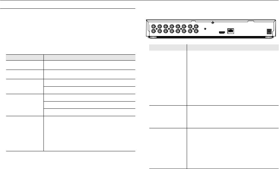
Part Names and Functions (Rear)
SPE-410 |
|
|
|
|
|
a bc |
d |
e f |
g |
||
|
|
RS485 |
ALARM IN |
ALARM OUT |
|
|
|
1 2 |
|
||
|
POWER |
ALARM |
G 1 2 3 4 G G NO COM NC NO COM G |
|
|
NETWORK |
DC 12V POWER |
|
CONSOLE HDMI |
AUDIO OUT |
|
Part Names |
|
|
|
Functions |
|
a Network connection |
|
This is a terminal that connects to the network through PoE or Ethernet cable. |
|||
b DC 12V |
|
This is a network video encoder power connection terminal. |
|||
c LED lamp |
|
ALARM : Lights up when an event occurs. |
|
||
|
POWER : Displays the power ON/OFF status. |
|
|||
|
|
|
|||
I/O terminal
RS485: Used for RS-485 communication.
d *preparation.NVR compatibility is under ALARM IN: Alarm input terminal. (1 - 4 channels) ALARM OUT: Alarm output terminal. (1 - 2 channels)
e CONSOLE |
This is the console connection terminal. |
|
|
|
This is the terminal that is used to check the test video. You can check the test video by |
f HDMI video output |
connecting to the portable display using the HDMI cable. |
` You can view the video in 4 split screens. Only FHD video is supported. |
|
|
` |
g Audio output |
This is the video signal output terminal (RCA jack). |
MM`` [CONSOLE] is designed for the service repair purpose only.
SPE-1610
|
|
|
a |
|
|
|
b c d efg |
|
|
h |
|
|
|
|
|
i |
|||||||
CH1 |
CH3 |
CH5 |
CH7 |
CH9 |
CH11 |
CH13 |
CH15 |
CH1 |
CH3 |
|
|
|
|
G |
RS485 |
ALARM OUT1 |
G |
1 |
2 |
ALARM IN |
7 |
8 |
G |
|
|
|
|
|
|
|
|
|
|
|
|
|
|
|
G NO COM NC G |
3 4 5 6 |
|||||||
|
|
|
|
|
|
|
|
|
|
|
|
|
|
|
|
|
|
|
|
|
|
|
POWER |
|
|
|
|
|
|
|
|
|
|
|
|
|
|
|
|
|
|
|
|
|
|
|
DC 12V |
CH2 |
CH4 |
CH6 |
CH8 |
CH10 |
CH12 |
CH14 |
CH16 |
CH2 |
CH4 |
|
HDMI |
NETWORK |
RESET CONSOLE |
NO COMNO COMNO COM G G |
G |
9 10 11 12 13 14 15 16 |
G |
||||||
|
|
|
|
VIDEO IN |
|
|
|
AUDIO IN |
AUDIO OUT |
2 |
3 |
4 |
|
|
|||||||||
Part Names |
Functions |
a Video input |
This is the video signal input terminal (BNC type). |
|
|
b Audio input |
This is the audio signal input terminal (RCA jack) and the optional audio extension cable |
jack. |
|
c Audio output |
This is the video signal output terminal (RCA jack). |
|
|
|
This is the terminal that is used to check the test video. You can check the test video by |
d HDMI video output |
connecting to the portable display using the HDMI cable. |
` You can view the video in 16 split screens. Only FHD video is supported. |
|
|
` |
e Network connection |
This is the network connection terminal. |
This button is used to reset the encoder settings to their factory defaults. Press and hold for about 5 seconds to reboot.
f Initialization J When the encoder is initialized, the network setting is changed in order to use DHCP. If there is no DHCP server in the network, you can use the IP installer program to reconfigure the basic network settings (IP Address, Subnet Mask, Gateway, etc.).
g CONSOLE |
This is the console connection terminal. |
|
|
|
|
I/O terminal |
RS485: Used for RS-485 communication. |
|
|
||
|
||
h preparation.* NVR compatibility is under |
ALARM IN: Alarm input terminal. (1 - 16 channels) |
|
ALARM OUT: Alarm output terminal. (1 - 4 channels) |
||
|
||
|
|
|
i Power input |
This is the power input terminal. |
MM`` [CONSOLE] is designed for the service repair purpose only.
10_ overview

installation & connection
Please take note of the followings before using this product.
•• Do not use the product outdoor.
•• Do not spill water or liquid in the connection part of the product.
•• Do not impose the system to excessive shock or force.
•• Do not pull out the power plug forcefully.
•• Do not disassemble the product on your own.
•• Do not exceed the rated input/output range.
•• Use a certified power cord only.
•• For the product with an input ground, use a grounded power plug.
Checking the installation environment
When mounting the SPE-1610 on a rack, comply with the following instructions.
1.Please ensure that the rack inside is not sealed.
2.Please ensure the air is circulated through the inlet/outlet as shown in the picture.
3. If you pile up the prudcts or other rack-mount devices as shown in figure 1, secure room for ventilation or install a vent.
4. For natural air convection, place the inlet at the bottom of the rack and the outlet on top.
5. It is strongly recommended that a fan motor is installed at the inlet and the outlet for air circulation. (Please fit a filter at the inlet to screen dust or foreign substances.)
Rack Installation
Install the Bracket-Rack as shown in the figure, and then fasten the screws on both sides (2 screws on each side).
`` Remove the screws on the left and right side of the encoder before installation. `` Fix the screws not to be loosened by vibrations.
[Figure 1]
connectionin&●sta●ationll
English _11

installation & connection
Connecting with other Device
Connecting the camera
Connect the [VIDEO IN] port of the network video encoder to the video output port of the camera.
SPE-410
CH1 |
CH2 |
CH3 |
CH4 |
CH1 |
CH2 |
CH3 |
CH4 |
CH1 |
CH2 |
|
|
|
|
|
|
|
|
||
|
VIDEO IN |
|
|
AUDIO IN |
|
CH3 |
CH4 |
||
|
|
|
|
VIDEO IN RESET |
|||||
Camera
|
|
|
RS485 |
ALARM IN |
ALARM OUT |
|
|
|
|
1 |
2 |
||
|
POWER |
|
ALARM |
G 1 2 3 4 |
G G NO COM NC |
NO COM G |
|
|
|
||||
POWER |
Power
Ethernet
CONSOLE |
HDMI |
AUDIO OUT |
Monitor to install
SPE-1610
Monitor to install
CH1 |
CH3 |
CH5 |
CH7 |
CH9 |
CH11 |
CH13 |
CH15 |
CH1 |
CH3 |
|
|
|
G |
RS485 |
ALARM OUT1 |
G |
1 2 |
ALARM IN |
7 |
8 |
G |
|
|
|
|
|
|
|
|
|
|
|
|
|
|
|
G NO COM NC G |
3 4 |
5 6 |
||||||
|
|
|
|
|
|
|
|
|
|
|
|
|
|
|
|
|
|
|
|
|
|
POWER |
|
|
|
|
|
|
|
|
|
|
|
|
|
|
|
|
|
|
|
|
|
|
DC 12V |
|
CH4 |
CH6 |
CH8 |
CH10 |
CH12 |
CH14 |
CH16 |
CH2 |
CH4 |
|
HDMI |
RESET CONSOLE |
NO COMNO COMNO COM G G |
G |
9 10 11 12 |
13 14 15 16 |
G |
|||||
|
|
|
|
VIDEO IN |
|
|
|
AUDIO IN |
AUDIO OUT |
2 |
3 |
4 |
|
|
||||||||
Ethernet |
Power |
|
Camera
JJ`` The HDMI out terminal of the product is provided for easier installation, and is not recommended for monitoring purposes.
Ethernet Connection
Connect the Ethernet cable to the local network or to the Internet.
12_ installation & connection

Power Supply
Use the screwdriver to connect each line (+, –) of the power cable to the corresponding power port of the encoder.
JJ`` When connected to PoE and DC 12V power simultaneously, the device uses the external power (DC 12V). (SPE-410)
-- You can also use a router featuring PoE to supply power to the encoder. -- Use PoE that is compliant with the IEEE802.3af protocols.
-- It is recommended to use a single source for powering the equipment among PoE and DC 12V. `` Be careful not to reverse the polarity when you connect the power cable.
`` If you want to connect an external device, you must turn off the external device before proceeding.
`` Connect the set and the adapter power line first, and then connect the power cable to the outlet on the wall.
Power Cable Specification for Each Model
When the input is DC 12V :
|
|
|
|
|
|
|
|
Wire Type (AWG) |
|
#22 |
#20 |
|
#18 |
||
Cable Length (Max.) |
|
24m |
|
38m |
|
60m |
|
Network Cable Specification |
|
|
|
|
|
|
|
|
|
|
|
|
|
|
|
Item |
|
|
Contents |
|
|
Remark |
|
Connector |
|
RJ45 (10/100/1000BASE-T) |
|
|
|
|
|
Ethernet |
|
10/100/1000Base-T |
|
To operate with 1000BASE-T, a cable of |
|||
|
|
UTP-6 or higher should be used for the |
|||||
|
|
|
|
|
|
Giga hub. |
|
Cable |
|
UTP Category 6 |
|
|
|
|
|
Max Distance |
|
|
100M |
|
DC Resistance ≤ 0.188 Ω/m |
||
PoE Support |
|
IEEE 802.3af |
|
|
SPE-410 |
||
Connecting to Audio Input/Output
SPE-410
Speaker |
Amp |
Network |
|
Speaker |
|||
|
|
Microphone |
PC
Microphone
Amp
Microphone
connectionin&●sta●ationll
English _13

installation & connection
SPE-1610 |
Connecting to the I/O port box |
|
|
|
|
|
|
|
|
|
Microphone |
|
|
|
|
|
|
|
Connect the Alarm I/O signal to the corresponding port of the rear port box. |
|
|||||||||||||
|
|
|
|
|
|
|
|
|
|
|
|
|
|
|
|
|
|
|
|
|
|
|
|
|
|
|
|
|
|||
|
|
|
|
|
|
Amp |
|
|
|
|
|
|
|
|
|
|
|
|
MM |
`` |
We are preparing to provide the alarm input and output functions by connecting the encoder to the NVR. (You can check it on |
||||||||||
|
|
|
|
|
|
|
|
|
|
|
|
|
|
|
|
|
|
|
the homepage.) |
|
|
|
|
|
|
|
|
|
|
||
|
|
|
|
|
|
|
|
|
|
|
|
|
|
|
|
|
|
|
SPE-410 |
|
|
|
|
|
|
|
|
|
|
||
|
CH1 |
CH3 |
CH5 |
CH7 |
CH9 |
CH11 |
CH13 |
CH15 |
CH1 |
CH3 |
|
|
|
RS485 |
ALARM OUT1 |
G |
ALARM IN |
G |
|
|
|
|
|
|
|
|
|
|
|
|
|
|
|
|
|
|
|
|
|
|
|
|
|
|
|
G |
G NO COM NC G |
1 2 3 4 5 6 7 8 |
|
|
|
|
|
RS485 |
|
ALARM IN |
ALARM OUT |
|
|
|
|||
|
|
|
|
|
|
|
|
|
|
|
|
|
|
|
|
|
|
POWER |
|
|
|
|
|
G 1 |
1 |
2 |
|
|
|
||
|
|
|
|
|
|
|
|
|
|
|
|
|
|
|
|
|
|
DC 12V |
|
|
POWER |
ALARM |
|
2 3 4 |
G G NO COM NC NO COM G |
|
|
|
|||
|
CH2 |
CH4 |
CH6 |
CH8 |
CH10 |
CH12 |
CH14 |
CH16 |
CH2 |
CH4 |
|
HDMI |
NETWORK RESET CONSOLE |
NO COMNO COMNO COM G G |
G |
9 10 11 12 13 14 15 16 |
G |
|
|
|
|
|
|
|
|
|
|
|
|
|
|
|
|
|
|
|
VIDEO IN |
|
|
|
AUDIO IN |
AUDIO OUT |
2 3 |
4 |
|
|
|
|
NETWORK |
POWER |
|
|
|
|
|
CONSOLE |
HDMI |
AUDIO OUT |
|||||
|
|
|
|
|
|
|
|
|
|
|
|
|
|
|
|
|
|
|
|
|
|
|
|
|
|
||||||
|
|
|
|
|
|
|
|
|
|
|
|
|
|
|
|
|
|
|
|
|
|
|
|
|
|
|
|
||||
|
|
|
|
|
|
|
|
|
|
|
|
|
NETWORK |
|
|
|
PC |
|
|
|
|
|
|
|
|
|
|
|
|
|
|
|
|
|
|
|
|
|
|
|
|
|
|
|
|
|
|
|
|
|
|
RS485 |
|
ALARM IN |
|
ALARM OUT |
|
|
|||||
|
|
|
|
|
|
|
|
|
|
|
|
|
|
|
|
|
|
|
|
|
|
|
|
|
|||||||
|
|
|
|
|
|
|
|
|
|
|
|
|
Network |
|
|
|
|
|
|
|
|
|
1 |
2 |
|
|
|||||
|
|
|
|
|
Speaker |
|
|
Amp |
|
|
|
|
|
|
|
|
|
|
|
|
G 1 2 3 4 G G NO COM NC NO COM G |
|
|
||||||||
|
|
|
|
|
|
|
|
|
|
|
|
|
|
|
|
|
|
|
|
|
|
|
|
|
|
|
|
||||
|
|
|
|
|
|
|
|
|
|
|
|
|
|
|
|
|
|
|
|
|
|
|
|
|
|
|
|
|
|||
|
|
|
|
|
|
|
|
|
|
|
|
|
Microphone |
|
|
|
|
|
|
|
|
|
|
|
|
|
|
|
|
|
|
|
|
|
|
|
|
|
|
|
|
|
|
|
Speaker |
|
|
|
|
|
|
Camera |
|
|
|
|
|
|
|
|
|
|
|
1. Connect the AUDIO IN port of the encoder with the microphone or LINE OUT port of the amplifier that the |
|
|
|
|
|
|
|
|
|
|
|
|
|||||||||||||||||||
|
|
|
|
|
|
Sensor |
|
Alarm |
|
|
|||||||||||||||||||||
2. |
microphone is connected to. |
|
|
|
|
|
|
|
|
|
|
|
|
The alarm input and output ports are configured as shown below. |
|
||||||||||||||||
Connect the AUDIO OUT port of the encoder with the speaker or LINE IN port of the amplifier that the |
|
||||||||||||||||||||||||||||||
speaker is connected to. |
|
|
|
|
|
|
|
|
|
|
|
|
|
•• G : Terminal for alarm ground |
|
|
|
|
|
|
|
|
|
|
|||||||
3. Check the specifications for audio input. |
|
|
|
|
|
|
|
|
|
•• ALARM OUT 1 : NO(Normal Open), COM(Common), NC(Normal Closed) |
|
||||||||||||||||||||
MM`` Audio input is available for channels 1 to 4. The output is for 1 channel only. |
|
|
|
|
|
•• ALARM OUT 2 : NO(Normal Open), COM(Common) |
|
|
|
||||||||||||||||||||||
|
|
|
|
|
•• ALARM IN 1 - 4 : Alarm input terminals |
|
|
|
|
|
|
|
|||||||||||||||||||
•• |
Audio Codec |
|
|
|
|
|
|
|
|
|
|
|
|
|
|
|
|
|
|
|
|
|
|
|
|
|
|
|
|
|
|
-- Audio In : G.711 PCM (Bit Rate: 64kbps / Sampling Frequency: 8kHz)
-- Audio Out : G.711 PCM (Bit Rate: 64kbps / Sampling Frequency: 8kHz)
•• Full duplex Audio
•• Audio in : Mono signal line input (Max.2.4 Vpp)
•• Audio out : Mono signal line output (Max.2.4 Vpp)
•• Line out impedance : 600Ω
14_ installation & connection

SPE-1610
CH1 |
CH3 |
CH5 |
CH7 |
CH9 |
CH11 |
CH13 |
CH15 |
CH1 |
CH3 |
RS485 |
ALARM OUT1 |
G |
1 |
2 |
ALARM IN |
7 |
8 |
G |
|
|
|
|
|
|
|
|
|
|
G |
G NO COM NC G |
3 4 5 6 |
||||||
|
|
|
|
|
|
|
|
|
|
|
|
|
|
|
|
|
|
POWER |
|
|
|
|
|
|
|
|
|
|
|
|
|
|
|
|
|
|
DC 12V |
CH2 |
CH4 |
CH6 |
CH8 |
CH10 |
CH12 |
CH14 |
CH16 |
CH2 |
CH4 |
|
|
|
|
|
|
|
|
|
AUDIO IN |
AUDIO OUT |
|
|
|
|
|
|
|
|
|||||||||
|
|
|
|
VIDEO IN |
|
|
|
|
|
|
|
|
|
|
|
|||
|
|
RS485 |
ALARM OUT1 |
|
ALARM IN |
|
|
|
|
G |
G NO COM NC G |
G |
1 2 3 4 5 6 7 8 |
G |
|
Camera |
ALARM2-4OUT |
2 3 |
4 |
|
|
|
Sensor |
|
|
NO COMNO COMNO COM G G |
G |
9 10 11 12 13 14 15 16 |
G |
|
|
Alarm
The alarm input and output ports are configured as shown below.
•• G : Terminal for alarm ground
•• ALARM OUT 1 : NO(Normal Open), COM(Common), NC(Normal Closed)
•• ALARM OUT 2 ~ 4 : NO(Normal Open), COM(Common)
•• ALARM IN 1 ~ 16 : Alarm input terminals
ALARM OUT |
ALARM IN |
ALARM IN |
(30VDC 2A, |
(5mA sink) |
(5mA sink) |
125VAC 0.5A MAX) |
|
|
Connecting to the Alarm Input
Connect one signal cable (out of 2) of applicable sensor to the [ALARM IN] port, and the other to the [G] port.
Connecting the Alarm Output
Connect one signal cable (out of 2) of applicable external device to the [ALARM OUT], and the other to the [COM] port.
MM`` You must use the specific RS-485 alarm I/O ports for each channel.
Connecting to the RS-485 device
Connect the external device to the [RS-485 +, -] ports.
You can connect and control PTZ camera that supports RS-485 communication.
MM`` You can connect and control the PTZ camera which supports the RS-485 communication. `` You can control these by connecting the AUX function that supports RS-485 communication. `` Check if the RS-485 device is compatible with the product first.
`` Pay attention not to change the polarity (+/-) of the RS-485 device when connecting it. `` For further information, refer to the respective Camera’s documentation.
connectionin&●sta●ationll
English _15
network connection and setup
You can set up the network settings according to your network configurations.
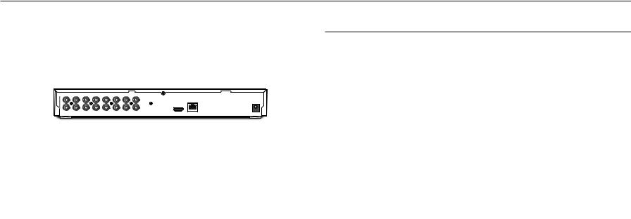
Connecting to Network through Ethernet (10/100/1000BaseT)
The connection is made using the network connection terminal on the back of the product. The figure below shows the product of SPE-1610 as an example.
1.Launch an Internet browser on the local PC.
2.Enter the IP address of the encoder in the address bar of the browser.
CH1 |
CH3 |
CH5 |
CH7 |
CH9 |
CH11 |
CH13 |
CH15 |
CH1 |
CH3 |
|
G |
RS485 |
ALARM OUT1 |
G |
1 2 |
ALARM IN |
7 |
8 |
G |
||
|
|
|
|
|
|
|
|
|
|
|
|
G NO COM NC G |
3 4 |
5 6 |
|||||||
|
|
|
|
|
|
|
|
|
|
|
|
|
|
|
|
|
|
|
|
POWER |
|
|
|
|
|
|
|
|
|
|
|
|
|
|
|
|
|
|
|
|
|
DC 12V |
|
CH2 |
CH4 |
CH6 |
CH8 |
CH10 |
CH12 |
CH14 |
CH16 |
CH2 |
CH4 |
|
NO COMNO COMNO COM G G |
G 9 10 11 12 |
13 14 15 16 |
G |
|||||||
AUDIO IN |
AUDIO OUT |
||||||||||||||||||||
|
|
|
|
VIDEO IN |
|
|
|
2 |
3 |
4 |
|
|
|
|
|
|
|
||||
Network
NETWORK
Hub/Switcher
Windows
Network Viewer
Hub/Switcher
MM`` A remote PC in an external Internet out of the LAN network may not be able to connect to the encoder installed in the intranet if the port-forwarding is not properly set or a firewall is set.
In this case, to resolve the problem, contact your network administrator.
`` In the IP installer, you can use the initial password, “4321” to set IP Address, Subnet Mask, Gateway, HTTP Port, VNP Port, IP type. After changing the network interface, for better security, access the web viewer and change the password.
`` By factory default, the IP address will be assigned from the DHCP server automatically. If there is no DHCP server available, the IP address will be set to 192.168.1.100.
To change the IP address, use the IP Installer.
For further details on IP Installer use, refer to “Static IP Setup”. (Page 18)
Connecting the encoder Directly to a DHCP Based DSL/Cable Modem
The connection is made using the network connection terminal on the back of the product. The figure below shows the product of SPE-410 as an example.
|
RS485 |
ALARM IN |
ALARM OUT |
|
|
|
|
1 |
2 |
|
|
||
POWER |
ALARM |
G 1 2 3 4 |
G G NO COM NC NO COM G |
|
|
|
|
POWER |
|
|
CONSOLE |
HDMI |
AUDIO OUT |
|
|
|
|
|||
Network
NETWORK
DSL/Cable Modem
Windows
Network Viewer
Hub/Switcher
1.Connect the user PC directly with the network encoder.
2.Run the IP Installer and change the IP address of the encoder so that you can use the web browser on your desktop to connect to the Internet.
3.Use the Internet browser to connect to the web viewer.
4.Move to [Setup] page.
5.Move to [Network] – [DDNS] and configure the DDNS settings.
6.Move to [Basic] – [IP & Port], and set the IP type to [DHCP].
7.Connect the encoder, which was removed from your PC, directly to the modem.
8.Restart the encoder.
MM`` |
For configuring the DDNS settings, refer to “DDNS”. (page 32) |
`` |
For registering the DDNS settings, refer to “Registering with DDNS”. (page 32) |
`` |
Refer to “IP & Port” for how to setup IP. (page 29) |
16_ network connection and setup

Connecting to Network through PPPoE
The connection is made using the network connection terminal on the back of the product. The figure below shows the product of SPE-410 as an example.
|
RS485 |
ALARM IN |
ALARM OUT |
|
|
|
|
1 |
2 |
|
|
||
POWER |
ALARM |
G 1 2 3 4 |
G G NO COM NC NO COM G |
|
|
|
|
POWER |
|
|
CONSOLE |
HDMI |
AUDIO OUT |
|
|
|
|
|||
Network
NETWORK
PPPoE Modem
Windows
Network Viewer
Hub/Switcher
1.Connect the user PC directly with the network encoder.
2.Run the IP Installer and change the IP address of the encoder so that you can use the web browser on your desktop to connect to the Internet.
3.Use the Internet browser to connect to the web viewer.
4.Move to [Setup] page.
5.Move to [Network] – [DDNS] and configure the DDNS settings.
6.Move to [Basic] – [IP & Port] Setup Page, set the IP type to [PPPoE], and enter the network service’s ID and password.
7.Connect the encoder, which was removed from your PC, directly to the modem.
8.Restart the encoder.
MM`` |
For configuring the DDNS settings, refer to “DDNS”. (page 32) |
`` |
For registering the DDNS settings, refer to “Registering with DDNS”. (page 32) |
`` |
Refer to “IP & Port” for how to setup IP. (page 29) |
Connecting to the Network using the router
This is for a small network environment such as homes, SOHO and ordinary shops.
The connection is made using the network connection terminal on the back of the product. The figure below shows the product of SPE-410 as an example.
|
RS485 |
ALARM IN |
ALARM OUT |
|
|
|
|
1 |
2 |
|
|
||
POWER |
ALARM |
G 1 2 3 4 |
G G NO COM NC NO COM G |
|
|
|
|
POWER |
|
|
CONSOLE |
HDMI |
AUDIO OUT |
|
|
|
|
|||
xDSL or Cable Modem
NETWORK
Broadband Router
xDSL or Cable Modem |
Network |
|
DDNS Server


 (Data Center, KOREA) External Remote PC
Configuring the network settings of the local PC connected to a Broadband Router
Configuring the network settings of the local PC connected to a Broadband Router, follow the instructions below.
•• Select : <Network> <Properties> <Local Area Connection> <General> <Properties> <Internet Protocol (TCP/IP)> <Properties> <Obtain an IP address automatically> or <Use the following IP address>.
•• Follow the instructions below if you select <Use the following IP address>:
ex1) If the address (LAN IP) of the Broadband Router is 192.168.1.1 IP address : 192.168.1.100
Subnet Mask : 255.255.255.0
Default Gateway : 192.168.1.1
ex2) If the address (LAN IP) of the Broadband Router is 192.168.0.1 IP address : 192.168.0.100
Subnet Mask : 255.255.255.0
Default Gateway : 192.168.0.1
ex3) If the address (LAN IP) of the Broadband Router is 192.168.xxx.1 IP address : 192.168.xxx.100
Subnet Mask : 255.255.255.0 Default Gateway : 192.168.xxx.1
MM`` For the address of the Broadband Router, refer to the product’s documentation.
`` For more information about port forwarding of the broadband router, refer to “Port Range Forward (Port Mapping) Setup”. (Page 20)
upd
networan connection●● k
English _17
network connection and setup
Buttons used in IP Installer
a b c d e f g
|
|
|
|
|
|
|
|
|
|
|
|
|
|
|
|
|
|
|
|
|
|
|
|
|
|
|
|
|
|
|
|
|
|
|
|
|
|
|
|
|
|
|
|
|
|
|
|
|
|
|
|
|
|
|
|
|
|
|
|
|
|
|
|
|
|
|
|
|
|
|
|
|
|
|
|
|
|
|
|
|
|
|
|
|
|
|
|
|
|
|
hi |
|
j k |
l m |
|||||||
|
|
|
|
|
|
|
|
|
|
|
|
|
|
|
|
|
Item |
|
|
|
|
|
|
|
Description |
||||||||
a Device Name |
|
Model name of the connected encoder. |
|
|
|
|
||||||||||
|
Click the column to sort the list by model name. |
|
|
|
|
|||||||||||
|
|
|
|
However, search will be stopped if clicked during the search. |
||||||||||||
b Alias |
|
This function is not currently implemented. |
|
|
|
|
||||||||||
c Mode |
|
Displays either <Static>, <Dynamic> or <PPPoE> for the current network connection |
||||||||||||||
|
status. |
|
|
|
|
|||||||||||
d MAC(Ethernet) Address |
|
Ethernet address for the connected encoder. |
|
|
|
|
||||||||||
|
Click the column to sort the list by Ethernet address. |
|||||||||||||||
|
|
|
|
However, search will be stopped if clicked during the search. |
||||||||||||
e IP Address |
|
IP address. |
|
|
|
|
||||||||||
|
Click the column to sort the list by IP address. |
|
|
|
|
|||||||||||
|
|
|
|
However, search will be stopped if clicked during the search. |
||||||||||||
f Protocol |
|
Network setting for the encoder. |
|
|
|
|
||||||||||
|
The factory default is “IPv4”. |
|
|
|
|
|||||||||||
|
|
|
|
Encoders with the IPv6 setting will be displayed “IPv6”. |
||||||||||||
g URL |
|
DDNS URL address enabling access from the external Internet. |
||||||||||||||
|
However, this will be replaced with the <IP Address> of the encoder if DDNS registration |
|||||||||||||||
|
|
|
|
has failed. |
|
|
|
|
||||||||
h IPv4 |
|
Scans for encoders with the IPv4 setting. |
|
|
|
|
||||||||||
Item |
Description |
i IPv6 |
Scans for encoders with the IPv6 setting. |
Activated in an IPv6 compliant environment only. |
|
j Search |
Scans for encoders that are currently connected to the network. |
However, this button will be grayed out if neither IPv4 nor IPv6 is checked. |
|
k Auto Set |
The IP Installer automatically configures the network settings. |
l Manual Set |
You should configure the network settings manually. |
m Exit |
Exits the IP Installer program. |
MM`` For the IP installer, use only the installer version provided in the installation CD or use the latest one if available. You can download the latest version from the Hanwha Techwin web site.
`` If the supporting OS is Windows 8.1, it is recommended that you use the Wisenet Device Manager instead of the IP Wisenet. The Wisenet Device Manager Program can be downloaded by visiting the Hanwha Techwin website (http://www.hanwhasecurity.com) under the menu <Customer Support> - <Technical Guides> - <Online Tool>.
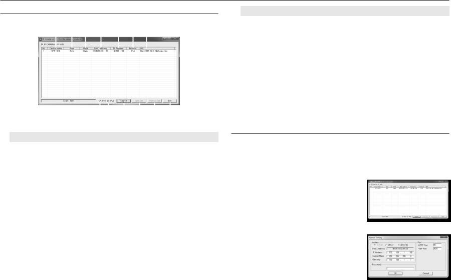
Static IP Setup
Manual Network Setup
Run <IP Installer_v2.XX.exe> to display the encoder search list.
At the initial startup, both [Auto Set] and [Manual Set] will be grayed out.
MM`` For encoders found with the IPv6 setting, these buttons will be grayed out as the encoders do not support this function.
1.Select an encoder in the search list.
Check the MAC address on the sticker attached to the encoder. Both the [Auto Set] and [Manual Set] buttons will be activated.
2.Click [Manual Set].
The Manual Setting dialog appears.
<IP Address>, <Subnet Mask>, <Gateway>, <HTTP Port>, and <VNP Port> of the encoder are displayed in the preset values.
3.In the <Address> pane, provide the necessary information.
•• MAC Address : The MAC address does not need to be set, as it is preset and displayed on the sticker attached to the encoder.
MM`` IP related parameters can be set only when DHCP is not checked.
18_ network connection and setup
 Loading...